EXPERIMENTAL AND NUMERICAL ANALYSIS OF SPRINGBACK IN DEEP DRAWING PROCESS
14
[Patil, 1(7): Sep, 2014] ISSN 2348 – 8034 GLOBAL JOURNAL OF ENGINEERING SCIENCE AND RESEARCHES EXPERIMENTAL AND NUMERICAL ANALYSIS OF SPRINGBACK IN DEEP DRAWING PROCESS Suryakant M Patil *1 , Prof. S. Magbul Hussain 2, Asst. Prof. K.Ravi Kumar 3 M Tech Research Scholar HITS Hyderabad *1 Professor, HITS Hyderabad 2 Assistant Professor Professor, HITS Hyderabad 3 ABSTRACT Many products in the automotive industry are produced with the deep drawing process. When the tools are released after the forming stage, the product springs back due to the action of internal stresses. Because the geometric tolerances can be tight for sheet metal products, this shape deviation can be unacceptable. In many cases spring back compensation is needed: the tools of the deep drawing process are changed so, that the product becomes geometrically accurate. In the industry, this is currently a costly and time consuming process of producing prototype products and redesigning the tools manually.In the case of deep drawing process, the spring back is an important phenomenon that leads to the modification of the part shape and dimensions after the tools removing. For this reason, in order to obtain a drawn part with a good accuracy of the shape and dimensions, this phenomenon must be controlled. The main cause of the spring back phenomenon is represented by the residual stress distribution on the sheet thickness of the drawn part. Hence, in order to control the spring back, the residual stress distribution on sheet thickness must be known and controlled. In this project an analysis was made concerning the influence of the residual stress distribution on the spring back intensity in the case of cylindrical drawn parts made from steel sheet[1] [23][32]. Deep drawing is a process for shaping flat sheets into cup-shaped articles without fracture or Excessive localized thinning. The design and control of a deep drawing process depends not only on the work piece material, but also on the condition at the tool work piece interface, the mechanics of plastic deformation and the equipment used. This project describes the use of ABAQUS finite element code in sheet metal forming simulation on circular cup deep drawing. It presents FEM based predictions in cup drawing simulation of aluminum alloys. In order to use the model in sheet metal forming simulations we have implemented it in a general purpose finite element code ABAQUS Two aluminum alloys, namely AA6061. and AA 7075 have been used for a validation of the model. For both alloys Simulations are done to study forming of AA6061, AA7075 aluminum sheets and study of variation of cup Height with temperature[6][7][9].111Equation Chapter 1 Section 1 Keywords :Deep drawing,Simulation. (C) Global Journal Of Engineering Science And Researches [15-24]
-
Upload
independent -
Category
Documents
-
view
2 -
download
0
Transcript of EXPERIMENTAL AND NUMERICAL ANALYSIS OF SPRINGBACK IN DEEP DRAWING PROCESS
[Patil, 1(7): Sep, 2014] ISSN 2348 – 8034
GLOBAL JOURNAL OF ENGINEERING SCIENCE AND RESEARCHESEXPERIMENTAL AND NUMERICAL ANALYSIS OF SPRINGBACK IN DEEP DRAWING
PROCESSSuryakant M Patil*1, Prof. S. Magbul Hussain2, Asst. Prof. K.Ravi Kumar3
M Tech Research Scholar HITS Hyderabad*1
Professor, HITS Hyderabad2
Assistant Professor Professor, HITS Hyderabad3
ABSTRACTMany products in the automotive industry are produced with the deep drawingprocess. When the tools are released after the forming stage, the productsprings back due to the action of internal stresses. Because the geometrictolerances can be tight for sheet metal products, this shape deviation can beunacceptable. In many cases spring back compensation is needed: the tools ofthe deep drawing process are changed so, that the product becomesgeometrically accurate. In the industry, this is currently a costly and timeconsuming process of producing prototype products and redesigning the toolsmanually.In the case of deep drawing process, the spring back is an importantphenomenon that leads to the modification of the part shape and dimensionsafter the tools removing. For this reason, in order to obtain a drawn partwith a good accuracy of the shape and dimensions, this phenomenon must becontrolled. The main cause of the spring back phenomenon is represented by theresidual stress distribution on the sheet thickness of the drawn part. Hence,in order to control the spring back, the residual stress distribution on sheetthickness must be known and controlled. In this project an analysis was madeconcerning the influence of the residual stress distribution on the springback intensity in the case of cylindrical drawn parts made from steel sheet[1][23][32].
Deep drawing is a process for shaping flat sheets into cup-shapedarticles without fracture or Excessive localized thinning. The design andcontrol of a deep drawing process depends not only on the work piece material,but also on the condition at the tool work piece interface, the mechanics ofplastic deformation and the equipment used. This project describes the use ofABAQUS finite element code in sheet metal forming simulation on circular cupdeep drawing. It presents FEM based predictions in cup drawing simulation ofaluminum alloys. In order to use the model in sheet metal forming simulationswe have implemented it in a general purpose finite element code ABAQUS Twoaluminum alloys, namely AA6061. and AA 7075 have been used for a validation ofthe model. For both alloys Simulations are done to study forming of AA6061,AA7075 aluminum sheets and study of variation of cup Height withtemperature[6][7][9].111Equation Chapter 1 Section 1
Keywords :Deep drawing,Simulation.
(C) Global Journal Of Engineering Science AndResearches
[15-24]
[Patil, 1(7): Sep, 2014] ISSN 2348 – 8034
I. INTRODUCTION
Sheet Metal Forming Casting, machining, powder metallurgy forming and are some of the importantmanufacturing processes used in engineering. In casting, a liquid material ispoured into a mould and then allowed to solidify in order to get the desiredshape. By casting even a very big and complex parts like engines of heavyvehicles can be made. Machining is next to casting and the required shape canbe obtained by removing excessive material from the work piece in the form ofchips. Cutting tool is used for removing material from the piece while coolingfluid dissipates the heat generated from the process. In powder metallurgyarticles can be produced by compacting the metal powder under requiredtemperature. The last method is metal forming. Out of four important metalforming processes i.e., Casting, machining, forming and powder metallurgy,metal forming is a major family where the plastic property of a metallicmaterials is utilized to form them into useful shapes[6].
Metal forming is further classified into sheet forming and bulk forming.Sheet forming is a type of metal forming by which bends, shallow and deeprecessed shapes can formed from a sheet metal. The initial work piece is insheet form generally called blank has a large surface area to volume ratio incontrast to the “billet” used in bulk forming which has low surface area tovolume ratio. Another difference is that the stretching is predominant insheet forming process, while compression is predominant in bulk forming[8].
. II. DEEP DRAWINGDeep drawing process of sheet metal is an essential means for forming of cupshaped components often having ample applications in automobile, beverage,aerospace, kitchen utensils, cartridge bases and zinc dry cells. This processunderwent lot of research in last two decades. In essence, the competitiveenvironment is still demanding for further high strength, light weight andthin walled parts in particular. In Deep drawing process a punch is utilizedto force a flat sheet metal (blank) to flow into the gap between the punch anddie surfaces. As a result, the blank can be formed into the various shapes. Asheet metal may be drawn into simple cylindrical-, conic- and boxed-shapedpart and also complicated parts which normally require redrawing processesusing progressive dies. Deep drawing process is popular due to its rapidprocess cycle times and its capability of producing complicated axisymmetricas well as non-axisymmetric geometries in few operations with low technicallabors requirement[7]. The important variables which affect the formability and outcomes of deepdrawing can be grouped into two categories:
(C) Global Journal Of Engineering Science AndResearches
[15-24]
[Patil, 1(7): Sep, 2014] ISSN 2348 – 8034
Material and friction factors; and Tooling and equipment factors.
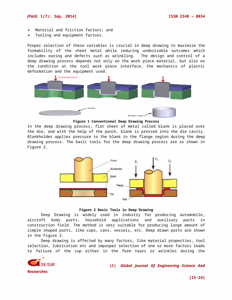
Proper selection of these variables is crucial in deep drawing to maximize theformability of the sheet metal while reducing undesirable outcomes whichincludes earing and defects such as wrinkling. The design and control of adeep drawing process depends not only on the work piece material, but also onthe condition at the tool work piece interface, the mechanics of plasticdeformation and the equipment used.
Figure 1 Conventional Deep Drawing ProcessIn the deep drawing process, flat sheet of metal called blank is placed overthe die, and with the help of the punch, blank is pressed into the die cavity.Blankholder applies pressure to the blank in the flange region during the deepdrawing process. The basic tools for the deep drawing process are as shown inFigure 2.
Figure 2 Basic Tools in Deep DrawingDeep Drawing is widely used in industry for producing automobile,
aircraft body parts, household applications and auxiliary parts inconstruction field. The method is very suitable for producing large amount ofsimple shaped parts, like cups, cans, vessels, etc. Deep drawn parts are shownin the Figure 2.
Deep drawing is affected by many factors, like material properties, toolselection, lubrication etc and improper selection of one or more factors leadsto failure of the cup either in the form tears or wrinkles during the
(C) Global Journal Of Engineering Science AndResearches
[15-24]
[Patil, 1(7): Sep, 2014] ISSN 2348 – 8034
process[1].Earing, necking, wrinkling, and poor surface appearance are the main
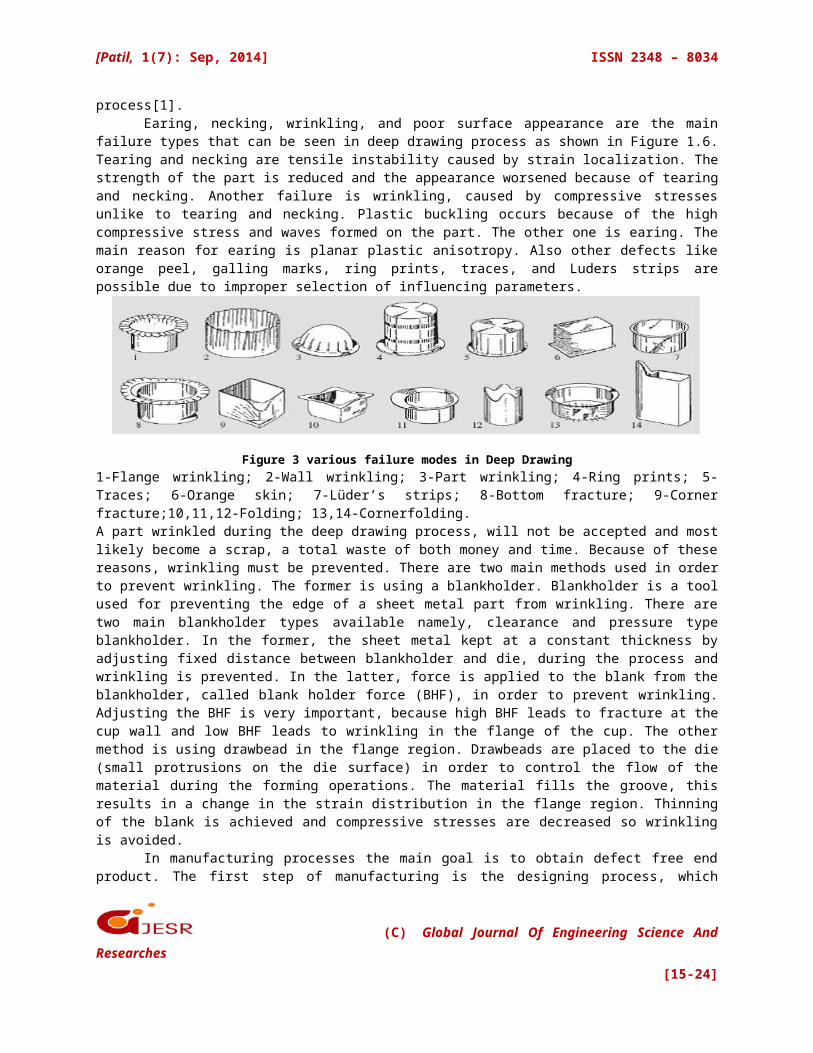
failure types that can be seen in deep drawing process as shown in Figure 1.6.Tearing and necking are tensile instability caused by strain localization. Thestrength of the part is reduced and the appearance worsened because of tearingand necking. Another failure is wrinkling, caused by compressive stressesunlike to tearing and necking. Plastic buckling occurs because of the highcompressive stress and waves formed on the part. The other one is earing. Themain reason for earing is planar plastic anisotropy. Also other defects likeorange peel, galling marks, ring prints, traces, and Luders strips arepossible due to improper selection of influencing parameters.
Figure 3 various failure modes in Deep Drawing1-Flange wrinkling; 2-Wall wrinkling; 3-Part wrinkling; 4-Ring prints; 5-Traces; 6-Orange skin; 7-Lüder’s strips; 8-Bottom fracture; 9-Cornerfracture;10,11,12-Folding; 13,14-Cornerfolding.A part wrinkled during the deep drawing process, will not be accepted and mostlikely become a scrap, a total waste of both money and time. Because of thesereasons, wrinkling must be prevented. There are two main methods used in orderto prevent wrinkling. The former is using a blankholder. Blankholder is a toolused for preventing the edge of a sheet metal part from wrinkling. There aretwo main blankholder types available namely, clearance and pressure typeblankholder. In the former, the sheet metal kept at a constant thickness byadjusting fixed distance between blankholder and die, during the process andwrinkling is prevented. In the latter, force is applied to the blank from theblankholder, called blank holder force (BHF), in order to prevent wrinkling.Adjusting the BHF is very important, because high BHF leads to fracture at thecup wall and low BHF leads to wrinkling in the flange of the cup. The othermethod is using drawbead in the flange region. Drawbeads are placed to the die(small protrusions on the die surface) in order to control the flow of thematerial during the forming operations. The material fills the groove, thisresults in a change in the strain distribution in the flange region. Thinningof the blank is achieved and compressive stresses are decreased so wrinklingis avoided.
In manufacturing processes the main goal is to obtain defect free endproduct. The first step of manufacturing is the designing process, which
(C) Global Journal Of Engineering Science AndResearches
[15-24]
[Patil, 1(7): Sep, 2014] ISSN 2348 – 8034
enormously affects the whole manufacturing process. The designer must haveknowledge about possible problems and their solutions during production. ManyResearches have been completed in various manufacturing processes because ofthe knowledge needed to achieve better quality product. This thesis willdiscuss about LDR determination and check safe levels of strain developed withstandard FLD for commercially available aluminum sheet metal[12].
III. CONCEPT OF DEEP DRAWING PROCESSSheet metal is a thin and flat piece of metal with thickness ranging between0.15mm and 6.5mm. It is widely used in engineering to produce a large varietyof products which includes containers, beverage cans, household applications,automotive parts, and aircraft panels. Sheet metal may be formed into desiredgeometry using various processes which includes deep drawing, shallow drawing,bending, blanking and stretch forming. The present study involves the study ofdeep drawing process[6].
Deep drawing is a process to form sheet metals using deep drawing die. Apunch is used to force the sheet metal to flow into the gap between the punchand the die. As a result, a cylindrical-, conical- or box-shaped part isformed in the die with minimal material wastage. One of the most commonexamples of deep drawing is the cup-drawing operation. It is used to produceproducts such as cartridge bases, zinc dry cells, metal cans and steelpressure vessels. It is also used as a method for formability test of sheetmetals such as the Swift cupping test.
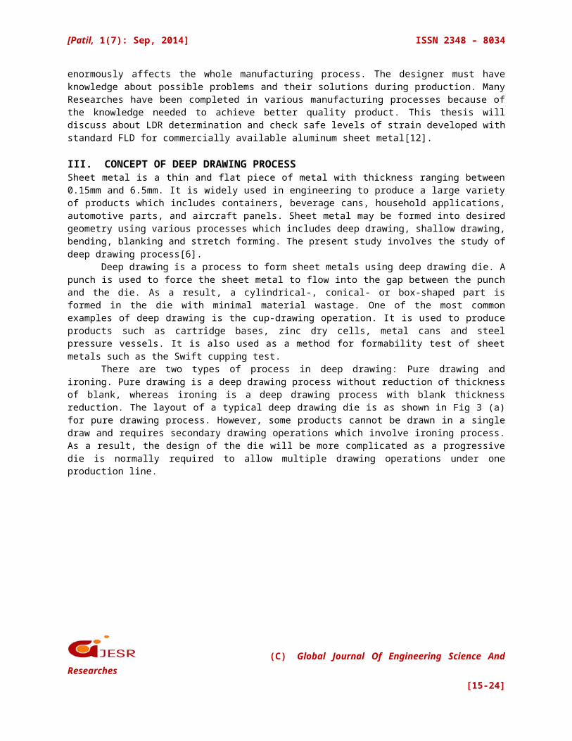
There are two types of process in deep drawing: Pure drawing andironing. Pure drawing is a deep drawing process without reduction of thicknessof blank, whereas ironing is a deep drawing process with blank thicknessreduction. The layout of a typical deep drawing die is as shown in Fig 3 (a)for pure drawing process. However, some products cannot be drawn in a singledraw and requires secondary drawing operations which involve ironing process.As a result, the design of the die will be more complicated as a progressivedie is normally required to allow multiple drawing operations under oneproduction line.
(C) Global Journal Of Engineering Science AndResearches
[15-24]
[Patil, 1(7): Sep, 2014] ISSN 2348 – 8034
Figure 3 A schematic illustration of drawing process: (a) Pure Drawing; (b) Ironing.
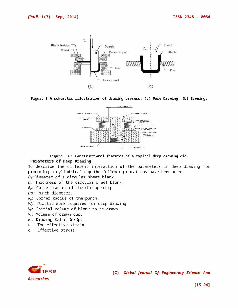
Figure 3.1 Constructional features of a typical deep drawing die. Parameters of Deep Drawing To describe the different interaction of the parameters in deep drawing forproducing a cylindrical cup the following notations have been used. D0:Diameter of a circular sheet blank. t0: Thickness of the circular sheet blank. Rd: Corner radius of the die opening. Dp: Punch diameter. Rp: Corner Radius of the punch. Wp: Plastic Work required for deep drawing V0: Initial volume of blank to be drawn Vc: Volume of drawn cup. R : Drawing Ratio Do/Dp. ε : The effective strain. σ : Effective stress.
(C) Global Journal Of Engineering Science AndResearches
[15-24]
[Patil, 1(7): Sep, 2014] ISSN 2348 – 8034
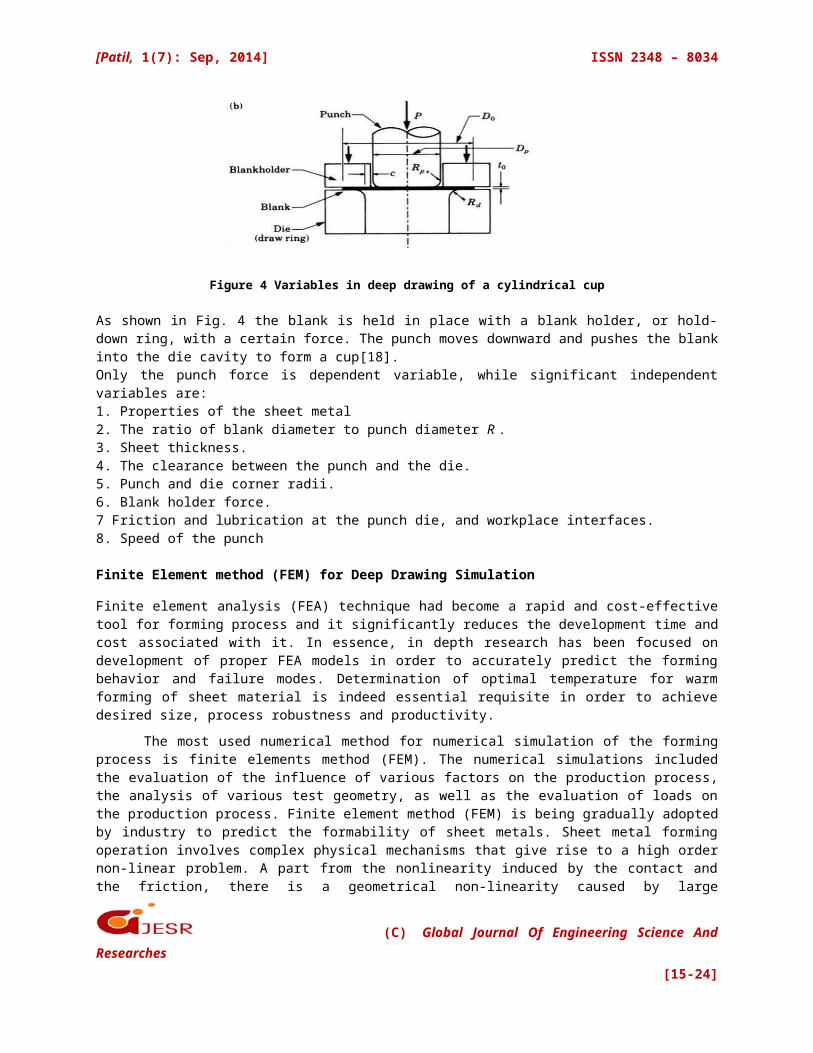
Figure 4 Variables in deep drawing of a cylindrical cup
As shown in Fig. 4 the blank is held in place with a blank holder, or hold-down ring, with a certain force. The punch moves downward and pushes the blankinto the die cavity to form a cup[18]. Only the punch force is dependent variable, while significant independentvariables are: 1. Properties of the sheet metal 2. The ratio of blank diameter to punch diameter R .3. Sheet thickness. 4. The clearance between the punch and the die. 5. Punch and die corner radii. 6. Blank holder force. 7 Friction and lubrication at the punch die, and workplace interfaces. 8. Speed of the punch
Finite Element method (FEM) for Deep Drawing Simulation
Finite element analysis (FEA) technique had become a rapid and cost-effectivetool for forming process and it significantly reduces the development time andcost associated with it. In essence, in depth research has been focused ondevelopment of proper FEA models in order to accurately predict the formingbehavior and failure modes. Determination of optimal temperature for warmforming of sheet material is indeed essential requisite in order to achievedesired size, process robustness and productivity.
The most used numerical method for numerical simulation of the formingprocess is finite elements method (FEM). The numerical simulations includedthe evaluation of the influence of various factors on the production process,the analysis of various test geometry, as well as the evaluation of loads onthe production process. Finite element method (FEM) is being gradually adoptedby industry to predict the formability of sheet metals. Sheet metal formingoperation involves complex physical mechanisms that give rise to a high ordernon-linear problem. A part from the nonlinearity induced by the contact andthe friction, there is a geometrical non-linearity caused by large
(C) Global Journal Of Engineering Science AndResearches
[15-24]
[Patil, 1(7): Sep, 2014] ISSN 2348 – 8034
displacement and large deformation. Furthermore, non-linear material behaviorssuch as plasticity make the problem even more difficult to be solvedanalytically. Therefore, numerical techniques, such as FEM, are usually usedto deal with this kind of problem. FEM can provide not only the final results,but also the information of intermediate steps, like the distributions ofdisplacement, stress, strain and other internal variables[24].
IV. RESULTS AND DISCUSSION
In this study, forming of pure aluminum has been analyzed using CGSA and twodifferent aluminum alloys has been simulated for circular cup drawing usingABAQUS. It has been confirmed that higher cup depth is possible at elevatedtemperatures. The following studies are made and plotted
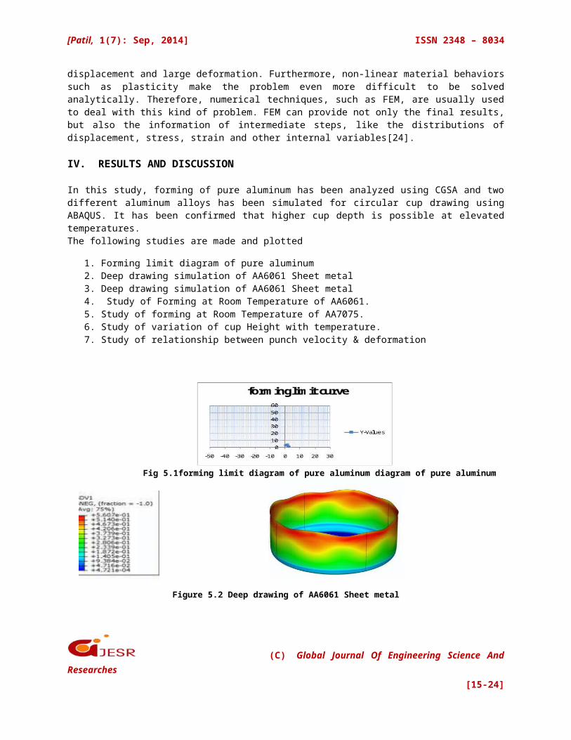
1. Forming limit diagram of pure aluminum2. Deep drawing simulation of AA6061 Sheet metal3. Deep drawing simulation of AA6061 Sheet metal4. Study of Forming at Room Temperature of AA6061.5. Study of forming at Room Temperature of AA7075.6. Study of variation of cup Height with temperature.7. Study of relationship between punch velocity & deformation
Fig 5.1forming limit diagram of pure aluminum diagram of pure aluminum
Figure 5.2 Deep drawing of AA6061 Sheet metal
(C) Global Journal Of Engineering Science AndResearches
[15-24]
[Patil, 1(7): Sep, 2014] ISSN 2348 – 8034
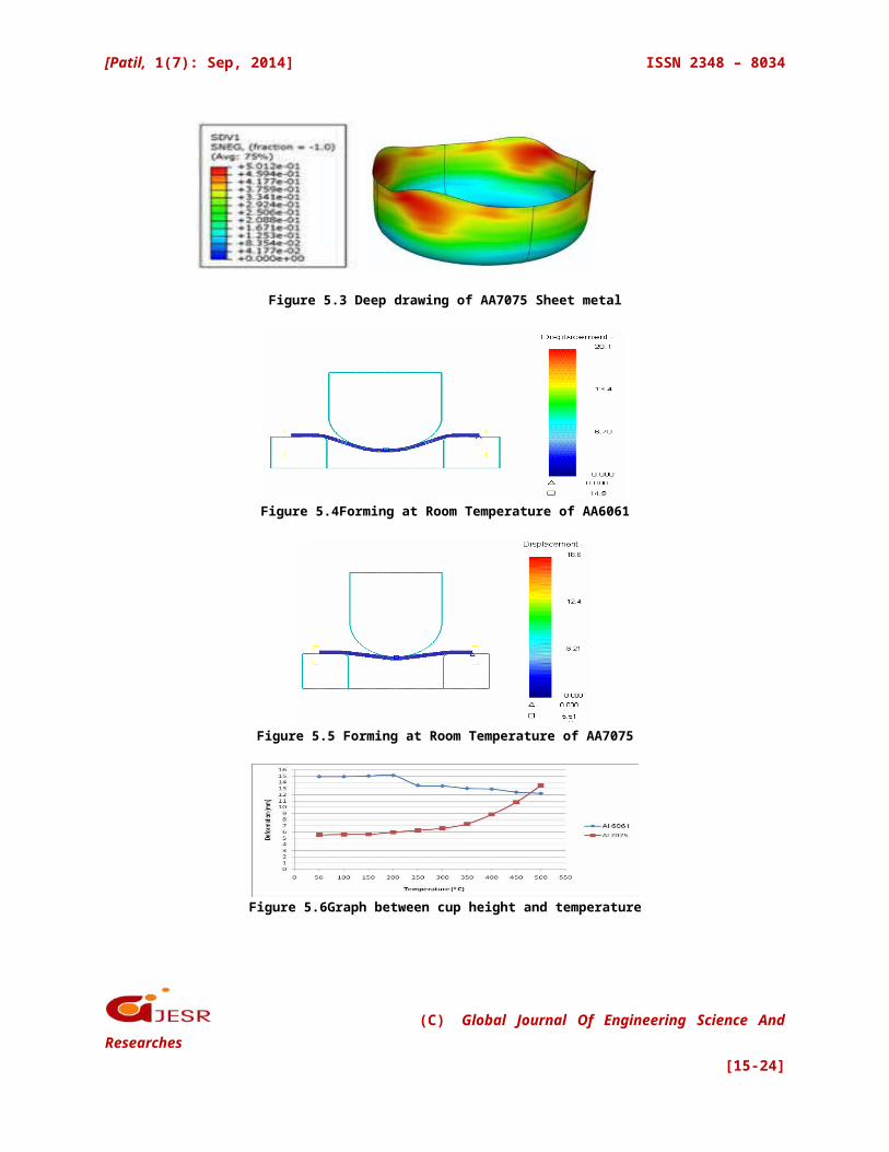
Figure 5.3 Deep drawing of AA7075 Sheet metal
Figure 5.4Forming at Room Temperature of AA6061
Figure 5.5 Forming at Room Temperature of AA7075
Figure 5.6Graph between cup height and temperature
(C) Global Journal Of Engineering Science AndResearches
[15-24]
[Patil, 1(7): Sep, 2014] ISSN 2348 – 8034
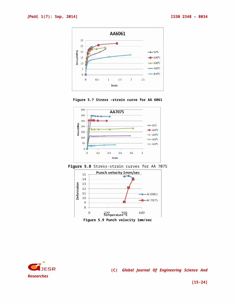
Figure 5.7 Stress –strain curve for AA 6061
Figure 5.8 Stress-strain curves for AA 7075
Figure 5.9 Punch velocity 1mm/sec
(C) Global Journal Of Engineering Science AndResearches
[15-24]
[Patil, 1(7): Sep, 2014] ISSN 2348 – 8034
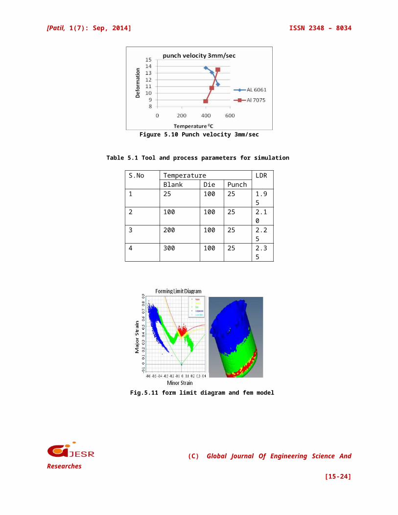
Figure 5.10 Punch velocity 3mm/sec
Table 5.1 Tool and process parameters for simulation
S.No Temperature LDRBlank Die Punch
1 25 100 25 1.95
2 100 100 25 2.10
3 200 100 25 2.25
4 300 100 25 2.35
Fig.5.11 form limit diagram and fem model
(C) Global Journal Of Engineering Science AndResearches
[15-24]
[Patil, 1(7): Sep, 2014] ISSN 2348 – 8034
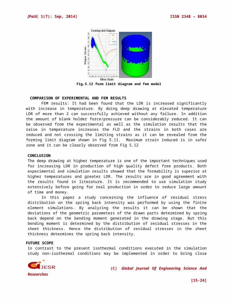
Fig.5.12 form limit diagram and fem model
COMPARISON OF EXPERIMENTAL AND FEM RESULTS FEM results: It had been found that the LDR is increased significantly
with increase in temperature. By doing deep drawing at elevated temperatureLDR of more than 2 can successfully achieved without any failure. In additionthe amount of blank holder force/pressure can be considerably reduced. It canbe observed from the experimental as well as the simulation results that theraise in temperature increases the FLD and the strains in both cases arereduced and not crossing the limiting strains as it can be revealed from theforming limit diagram shown in Fig 5.11. Maximum strain induced is in saferzone and it can be clearly observed from Fig 5.12
CONCLUSIONThe deep drawing at higher temperature is one of the important techniques usedfor increasing LDR in production of high quality defect free products. Bothexperimental and simulation results showed that the formability is superior athigher temperatures and greater LDR. The results are in good agreement withthe results found in literature. It is recommended to use simulation studyextensively before going for real production in order to reduce large amountof time and money.
In this paper a study concerning the influence of residual stressdistribution on the spring back intensity was performed by using the finiteelement simulations. By analyzing the results it can be shown that thedeviations of the geometric parameters of the drawn parts determined by springback depend on the bending moment generated in the drawing stage. But thisbending moment is determined by the distribution of residual stresses in thesheet thickness. Hence the distribution of residual stresses in the sheetthickness determines the spring back intensity.
FUTURE SCOPEIn contrast to the present isothermal conditions executed in the simulationstudy non-isothermal conditions may be implemented in order to bring close
(C) Global Journal Of Engineering Science AndResearches
[15-24]
[Patil, 1(7): Sep, 2014] ISSN 2348 – 8034
relations between experimental and simulations, as non-isothermal conditionsare involved in practical conditions due to loss of heat from the blank. Ithas to be tested for improvement if any due to non-isothermal conditions oftools set up.
V. REFERENCES
[1]Prakash Sonis, N. Venkat Reddy and G K Lal, On Multistage Deep Drawing of AxisymmetricComponents, Journal of Manufacturing Science and Engineering, Transactions of SME, vol 125, (2003), pp352 - 361 Tyng-Bin Huanga, , Yung-An Tsai a, Fuh-KuoChenb∗[2]Tyng- Bin Huang, Yung-An Tsai and Fuh-Kuo Chen , Finite element analysis and formability of non-isothermal deep drawing of AZ31Bsheets, Journal of materials processing technology,177(2006), 142-145 [3] Syed MujahedHussaini, Swadesh Kumar Singh and Amit Kumar Gupta, Formability and fracturestudies of austenitic stainless steel 316 at different temperatures, Journal of King Saud University –Engineering Sciences 2013, (article in press)[4] Fuh-Kuo Chen and Kuan-Hua Chiu, Stamping formability of pure titanium sheets, Journal of MaterialsProcessing Technology 170 (2005) 181–186[5] Y.Marumo, H Saiki and L Ruan, Effect of sheet thickness on deep drawing of metal foils, Journal ofAchievements in materials and manufacturing Engineering, volume 20(2007), short paper, pp479- 482[6] A Fizal and B M Dariani, Theoretical and Experimental Analysis of Axisymmetric HydromechanicalDeep Drawing Process, proceedings of the institution of Mechanical Engineers, Part B: Journal ofEngineering manufacture 2006 200, 1429-1437[6] ParvizKahhal, Seyed Yousef AhmadiBrooghani and HamedDeilamiAzodi, Multi-objective optimizationof sheet metal forming die using FEA coupled with RSM(2013) pp 3835- 3842[7] Dong Hwan Park and Prasad K D Yarlagadda, Computer Aided Process Planning for NonAxisymmetricDeep Drawing products, American Institute of Physics Conference proceedings , 712,1985(2004) [8] M Jain, J Allin and M J Bull, Deep Drawing Charectiristics of Automotive Aluminium Alloys, MaterialsScience and Engineering (1998) 69-82[9] L Wang and T C Lee, Numirical Simulation of the Effects of the Space-Varient Blank-Holder Force andGeometrical Variables in the Deep – Drawing process, Journal of Strain Analysis, Institution of MechanicalEngineers,2005, 375-384[10] K S Deep N Venkat Reddy A Agararwal and J Ramkumar, A Mathematical Model for Determination ofLimiting Blank Holding Force and Cavity Pressure in Hydromechanical Deep Drawing, Journal ofEngineering Manufacture, Institution of Mechanical Engineers, Strain Analysis, Institution of MechanicalEngineers, Vol,221 Part B, 2007, 156-162[11] A Fazil and B MollaeiDariani, Parameter Study of the Axisymmetric Hydromechanical Deep DrawingProcess, Journal of Engineering Manufacture, Institution of Mechanical Engineers vol 220 2006 , 1937-1944[12]H.Gharib, A S Wifi, M. Younam and A Nassef, optimization of the blank holder force in cup drawing,Journal of the blank holder force in cup drawing, volume 18, issue 1-2, Dec-Oct 2006 , 291-294.[13]A S Korhonen, Drawing Force in Deep Drawing of Cylindrical Cup with Flat-Nosed Punch, Journal ofEngineering for industry, ASME, Vol 104, 1982, 29-37[14] S. Thiruvarudchelvan, W G Lewis, Deep Drawing with Blank Holder Force Approximately Proportionalto the Punch Force, Journal of Engineering Industry, Transactions of ASME, Vol 112, (1990) pp 278- 285
(C) Global Journal Of Engineering Science AndResearches
[15-24]
[Patil, 1(7): Sep, 2014] ISSN 2348 – 8034
[15]Basic Die Making by D.EugeneOstergaard, Mcgraw-Hill Book Company.[16]Fundamentals of engineering Design Dr.S.K.Basu,Dr.S.N.MukherjeeProf.R.Mishra,Oxford& IBHPublishing House[17]A. Ayres and M.L. Wenner, "Strain and Strain-Rate Hardening Effects in Punch Stretching of 5182-0Aluminum at Elevated Temperatures", Metallurgical Transactions A10A, 41-46 (1979).[18]D. Li and A.K. Ghosh, "Biaxial warm forming behavior of aluminum sheet alloys", Journal of MaterialsProcessing Technology 145, 281-293 (2004). [19][Takuda et al., 2002] Takuda, H.; Mori, K.; Masuda, I.; Abe, Y.; Matsuo,M.; "Finite element simulation ofwarm deep drawing of aluminium alloy sheet when accounting for heat conduction"; In Journal ofMaterials Processing Technology 120, pp. 412-418 [20]D.Y. Yang, J.B. Kim, D.W. Lee, Investigations into the manufacturing of very long cups by mechanicaldeep drawing and ironing with controlled radial pressure force, Ann. CIRP 44 (1995) 255–258.[21]S. Thiruvarudchelvan, Blank holding pressure-assisted cup drawing processes: A review, ASMESingapore Chapter 1991/92 yearbook, pp 17-23.[22]K.Oberlander, The mechanical deep drawing and spinning of sheet metals-II, BlechRohreProfile 4(1982) 161–164.[23]L. Sobotová, E. Spišák, Analysis of influence of deepdrawing process on the surface quality of materialof pressings, ActaMechanicaSlovaca, vol. 9 (2005) 165-170.[24]A.B. da Rocha, A.D. Santos, P. Teixeira, M.C. Butuc, Analysis of plastic flow localization under strainpaths changes and its coupling with finite element simulation in sheet metal forming, J. Mat. Proc.Technol., vol. 209, No. 11 (2009) 5097-5109.[25]R. Von-Mises, Mechanik der festenKörperimplastischdeformablenZustand, Nachr. Ges.Wiss.Göttingen,Mathematisch-PhysikalischeKlasse (1913) 582-92.[26]M. T. Huber, Specific work of strain as a measure of material effort, CzasopismoTechniczne XXII, No. 3(1904) 38-40, No. 4 (1904) 49-50, No. 5 (1904) 61-63, No. 6 (1904) 80-81, Lvov.[27]D. Banabic, H.-J. Bunge, K. Pohlandt, A.E. Tekkaya, Formability of Metallic Materials, Springer-Verlag,2000.[28]Basic Die Making by D.EugeneOstergaard, Mcgraw-Hill Book Company.[29]Fundamentals of endineeringDesign,Dr.S.K.Basu,Dr.S.N.Mukherjee,Prof.R.Mishra,Oxford& IBHPublishing House[30]ABAQUS-User Manual[31]Design Hand Book,PSG[32]P.S. Bate, N. Ridley, B. Zhang and S. Dover, "Optimisation of the superplastic forming of aluminiumalloys."Journalof Materials Processing Technology 177, 91-94 (2006). [33]A. Ayres and M.L. Wenner, "Strain and Strain-Rate Hardening Effects in Punch Stretching of 5182-0Aluminum at Elevated Temperatures", Metallurgical Transactions A10A, 41-46 (1979).
(C) Global Journal Of Engineering Science AndResearches
[15-24]