practical engineering drawing
204
-
Upload
khangminh22 -
Category
Documents
-
view
0 -
download
0
Transcript of practical engineering drawing
PRACTICAL ENGINEERING DRAWINGAND
THIRD ANGLE PROJECTION
FOR STUDENTS IN SCIENTIFIC, TECHNICAL, AND MANUAL TRAINING SCHOOLS
AND FOR
ENGINEERING AND ARCHITECTURAL DRAUGHTSMEN, SHEET METAL WORKERS, ETC.
Frederick flecaton Willson, C.E., H.JVL,
Professor of Descriptiz<e Geometry^ Stereotonty and Technical Drawingin the
John C, Green School of Science, Princeton University.
YorkTHE MACMILLAN COMPANY
LONDON : MACMILLAN & CO., LTD.
1898
ALL RIGHTS RESERVED
COPYRIGHT 1896
BY
FREDERICK N. WILLSON.
PREFACE
INthis work the author has aimed to present, concisely and with illustration that should in especial
degree conduce to the interest of a course, not only the usual matter of first books on mechanical
drawing but also some of the additional topics which he regards as essential to the education
of a draughtsman, and which could be included without having the book exceed, either in size or
price, the leading works on the same subject, previously in the field.
Having in mind the needs, particularly, of those who have to regard more the immediate prac-
tical application of projections in shop work than the educational and disciplinary value of a course
in Descriptive Geometry, the author presents only the Third Angle Method of making working
drawings, now so generally employed in American draughting offices.
Since the pages were electrotyped an instrument of unusual convenience and merit has been
placed on the market, a compass whose legs remain parallel during the process of opening, and
which is therefore ready for use at all angles. Its importance justifies a reference to it here, since
it cannot conveniently be incorporated under its proper heading in the text.
The unity and continuity of the course here offered is not affected by the lack of consecutiveness
in the chapters, its issue in present shape having been contemplated at the time of writing, although
it originally appeared in the author's larger work Theoretical and Practical Graphics in close correla-
tion with a course on the Descriptive Geometry of Monge (First Angle Method) and its applications
in Shadows, Perspective, Trihedrals and Spherical Projections.
F. N. W.
TABLE OF CONTENTS
NOTE-TAKING, DIMENSIONING, ETC.
Technical Frec-Hand Sketching and Lettering.
Note -Taking from Measurement. Dimension-
ing. Conventional Representations.
Pages 5- 10.
THE DRAUGHTSMAN'S EQUIPMENT.The Choice and Use of Drawing Instruments and
the Various Elements of the Draughtsman's
Equipment. General remarks preliminary to
instrumental work.
Pages 11-20.
EXERCISES FOR PEN AND COMPASS.Kinds and Signification of Lines. Designs for
Elementary Practice with the Right Line Pen.
Standard Methods of Representing Materials.
Line Shading. Plane Problems of the RightLine and Circle, including Rankine's and
Kochansky's approximations. Exercises for the
Compass and Bow - pen, including uniform and
tapered curves. The Anchor Ring. The Hy-perboloid. A Standard Rail Section.
Pages 21-38.
ON HIGHER PLANE CURVES AND THE HELIX.
Regarding the Irregular Curve. The Helix.
The Ellipse, Hyperbola and Parabola, by various
methods of construction. Homological Plane
Curves. Relief - Perspective. Link - Motion
Curves. Centroids. The Cycloid. The
Companion to the Cycloid. The Curtate andProlate Trochoids. Hypo- , Epi-, and Peri-
Trochoids. Special Trochoids, as the Ellipse,
Straight Line, Lima;on, Cardioid, Trisectrix,
Involute and Spiral of Archimedes. Parallel
Curves. Conchoid. Quadratrix. Cissoid.
Tractrix. Witch of Agnesi. Cartesian
Ovals. Cassian Ovals. Catenary. Logarith-
mic Spiral. Hyperbolic Spiral. Lituus.
Ionic Volute.
Pages 39-78.
TINTING AND SHADING.
Brush Tinting, Flat and Graduated. Masonry,
Tiling, Wood Graining, River -Beds, elc., with
brush alone, or in combined brush and line work.
Pages 79-87.
THE LETTERING OF DRAWINGS.
Free -Hand Lettering. Mechanical Expedients.
Proportioning of Titles. Discussion of
Forms. Half- Block, Full Block and Railroad
Types. Borders and how to draw them.
(Alphabets in Appendix).
Pages 88-96.
BLUE -PRINTING AND OTHER PROCESSES.
The Blue -print Process. Photo-, and other Re-
productive Graphic Processes, including WoodEngraving, Cerography, Lithography, Photo-
lithography, Chromo- lithography, Photo -engrav-
ing,u Half- Tones," Photo - gravure and allied
processes, How to Prepare Drawings for Illustra-
tion.
Pages 97- 103.
THIRD ANGLE PROJECTION. WORKINGDRAWINGS.
Projections and Intersections by the Third AngleMethod. The Development of Surfaces, for
Sheet Metal or Arch Constructions. Working
Drawings of Bridge Post Connection. Struc-
tural Iron. Spur Gearing (Approximate Invo-
lute Outlines). Helical Springs, Rectangularand Circular Section. Screws and Bolts (U. S.
Standard), and Table of Proportions.
Pages 131- 180.
AXONOMETRIC (INCLUDING ISOMETRIC) PRO-JECTION. ONE - PLANE DESCRIPTIVE
GEOMETRY.
Orthographic Projection upon a Single Plane.
Axonometric Projection. General Fundamental
Problem, inclinations known for two of the three
axes. Isometric Projection vs. Isometric Draw-
ing. Shadows on Isometric Drawings. Tim-ber Framings and Arch Voussoirs in Isometric
View. One-Plane Descriptive Geometry.
Pages 241-247.
OBLIQUE PROJECTION.
Oblique or Clinographic Projection, Cavalier Per-
spective, Cabinet Projection, Military Perspec-tive. Applications to Timber Framings, ArchVoussoirs and Drawing of Crystals.
Pages 248-250.
APPENDIX.
Table of the Proportions of Washers. WorkingDrawings of Standard 100 - Ib. Rail, and of
Allen - Richardson Slide Valve. Designs for
Variation of Problems in Chapters X, XV and
XVI. Alphabets.
Pages 251 - 268.
FREE-HAND DRAWING.
CHAPTER II.
ARTISTIC AND TECHNICAL FREE-HAND DRAWING. SKETCHING FROM MEASUREMENT. FREE-
HAND LETTERING. CONVENTIONAL REPRESENTATIONS.
20. Drawings, if classified as to the method of their production, are either free-hand or mechanical;
Note Regarding the Non-consecutiveness of Page Numbers In this Work.
As already indicated in the preface to this and each of the other "parts
"or sections of the author's
work entitled Theoretical and Practical GmjjhicK, the pages are printed from theplates
of the large workthe most convenient arrangement for teachers using the latter with classes supplied with the different parts,but precluding, necessarily, the consccutiveness of page numbers throughout any one of the sections. This
docs not in the slightest degree affect the unity of either "part
" when employed as an independent work,its issue under separate cover having been contemplated and provided for when the large work was in
preparation. For the convenience of any, however, who wish to assure themselves of the completeness of
either volume in the series, this slip is inserted, containing the numbers of the pages of the large workthat each section is intended to include. (See page preceding the title-page for Table of Contents of
each section.)No. 1. Pages o-10; 88-9(5; Alphabets, 1-151.
No. '2. Pages 1.31-180, and Appendix ((5 pp.).No. 3. Pages -39-78 and Appendix.No. 4. Pages 5-10.3; 1-31-180; 241-250; Appendix, including Alphabets.No. 5. Pages 219-240, and (after September, 1899) Supplement (8 pp.) on Perspective of Reflections.
No. G. Pages ,39-78; 105-250; Appendix (8 pp.) and Index.
object. Yet to attain a sufficient degree of skill in it for all practical and commercial purposes is
possible to all, and among them many who could never hope to produce artistic results. It is con-
fined mainly to the making of working sketches, conventional representations and free-hand lettering, and
the equipment therefor consists of a pencil of medium grade as to hardness; lettering pens Falcon
or Gillott's 303, with Miller Bros. "Carbon" pen No. 4; either a note-book or a sketch-block or
pad; also the following for sketching from measurement: a two -foot pocket -rule; calipers, both
external and internal, for taking outside and inside diameters; a pair of pencil compasses for making
an occasional circle too large to be drawn absolutely free-hand; and a steel tape-measure for large
work, if one can have assistance in taking notes, but otherwise a long rod graduated to eighths.
TABLE OF CONTENTS
FREE-HAND DRAWING.
CHAPTER II.
ARTISTIC AND TECHNICAL FREE-HAND DRAWING. SKETCHING FROM MEASUREMENT. FREE-HAND LETTERING. CONVENTIONAL REPRESENTATIONS.
20. Drawings, if classified as to the method of their production, are either free-hand or mechanical;
while as to purpose they may be working drawings, so fully dimensioned that they can he worked
from and what they represent may be manufactured; or finished drawings, illustrative or artistic in
character and therefore shaded either with pen or brush, and having no hidden parts indicated bydotted lines as in the preceding division. Finished drawings also lack figured dimensions.
Working drawings of parts or"details
" of a structure are called detail drawings; while the
representation of a structure as a whole, with all its details in their proper relative position, hidden
parts indicated by dotted lines, etc., is termed a general or assembly drawing.
21. While mechanical drawing is involved in making the various essential views plans, eleva-
tions and sections of all engineering and architectural constructions, and in solving the problems of
form and relative position arising in their design, yet, to the engineer, the ability to sketch effectively
and rapidly, free-hand, is of scarcely less importance than to handle the drawing instruments skill-
fully ;while the success of an architect depends in still greater measure upon it.
We must distinguish, ho\vever, between artistic and technical free-hand work. The architect must
be master of both; the engineer necessarily only of the latter.
To secure the adoption of his designs the architect relies largely upon the effective way in which
he can finish, either with pen and ink or in water -colors, the perspectives of exterior and interior
views;
and such drawings are judged mainly from the artistic standpoint. While it is not the
province of this treatise to instruct in such work a word of suggestion may properly be introduced
for the student looking forward to architecture as a profession. He should procure Linfoot's Picture
Making in Pen and Ink, Miller's Essentials of Perspective and Delamotte's Art of Sketching from Nature;
and with an experienced architect or artist, if possible, but otherwise by himself, master the prin-
ciples and act on the instructions of these writers.
22. Since the camera makes it, fortunately, no longer essential that a civil engineer should be a
landscape artist as well, his free-hand work has become more restricted in its scope and more rigid
in its character, and like that of the machine designer it may properly be called technical, from its
object. Yet to attain a sufficient degree of skill in it for all practical and commercial purposes is
possible to all, and among them many who could never hope to produce artistic results. It is con-
fined mainly to the making of working sketches, conventional representations and free-hand lettering, and
the equipment therefor consists of a pencil of medium grade as to hardness; lettering pens Falcon
or Gillott's 303, with Miller Bros. "Carbon" pen No. 4; either a note-book or a sketch-block or
pad; also the following for sketching from measurement: a two -foot pocket -rule; calipers, both
external and internal, for taking outside and inside diameters; a pair of pencil compasses for makingan occasional circle too large to be drawn absolutely free-hand; and a steel tape-measure for large
work, if one can have assistance in taking notes, but otherwise a long rod graduated to eighths.
THEORETICAL AND PRACTICAL GRAPHICS.
23. In the evolution of a machine or other engineering project the designer places his ideas on
paper in the form of rough and mainly free-hand sketches, beginning with a general outline, or
"skeleton" drawing of the whole, on as large a scale as possible, then filling in the details, separate
and larger drawings of which are later made to exact scale. While such preliminary sketches are
not drawn literally"to scale
"it is obviously desirable that something like the relative proportions
should be preserved and that the closer the approximation thereto the clearer the idea they will
give to the draughtsman or workman who has to work from them. A habit of close observation
must therefore be cultivated, of analysis of form and of relative direction and proportion, by all
who would succeed in draughting, whether as designers or merely as copyists of existing construc-
tions. While the beginner belongs necessarily in the latter category he must not forget that his aim
should be to place himself in the ranks of the former, both by a thorough mastery of the funda-
mental theory that lies back of all correct design and by such training of the hand as shall facilitate
the graphic expression of his ideas. To that end he should improve every opportunity to put in
practice the following instructions as to
SKETCHING FROM MEASUREMENT,
as each structure sketched and measured will not only give exercise to the hand but also prove a
valuable object lesson in the proportioning of parts and the modes of their assemblage.
A free-hand sketch may be as good a working drawing as the exactly scaled and usually
hiked drawing that is generally made from it to be sent to the shop.
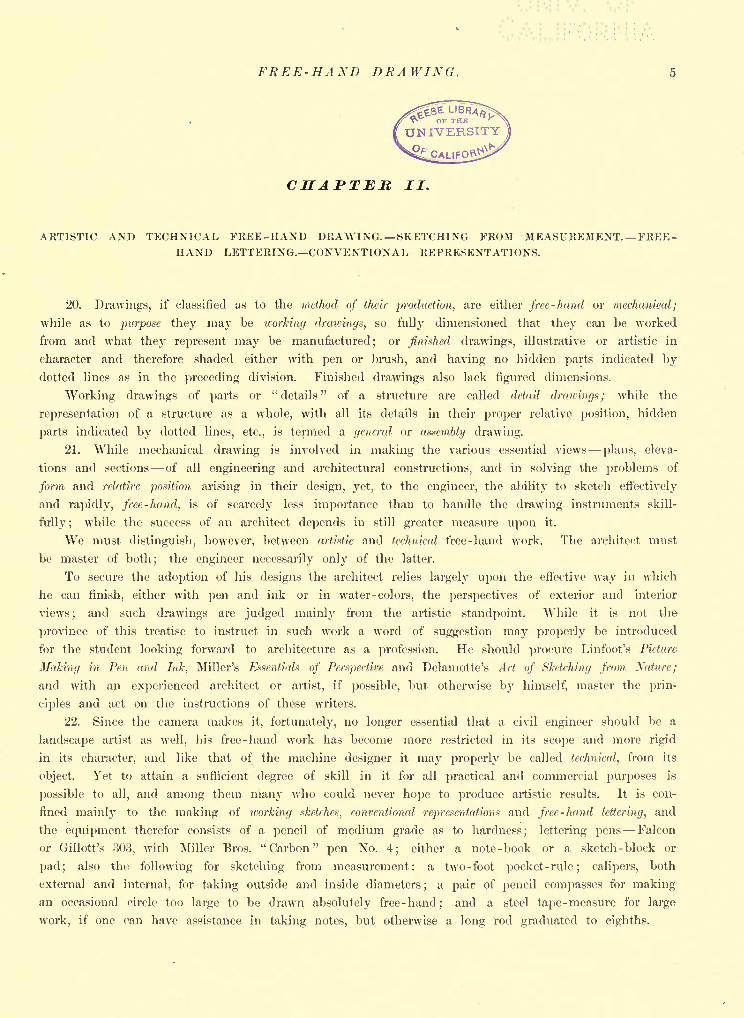
While several views are usually required, yet for objects of not too complicated form, and whose
lines lie mainly in mutually perpendicular directions, the method of representation illustrated by Fig.
7, is admirably adapted,* and obviates all necessity for additional sketches. It is an oblique projection
(Art. 17) the theory of whose construction will be found in a subsequent chapter, but with regard
to which it is sufficient at this point to say that the right angles of the front face are seen in
their true form, while the other right angles are shown either of 30, 60, or 120; although almost
any oblique angle will give the same general effect and may be adopted. Lines parallel to each
other on the object are also parallel in the drawing.
Draw first the front face, whose angles are seen in their true form;
then run the oblique lines
off in the direction which will give the best view. (Refer to Figs. 42, 44, 45 and 46.)
24. While Fig. 7 gives almost the pictorial effect of a true perspective and the object requires
no other description, yet for complicated and irregular forms it gives place to the plan- and - eleva -
tion mode of representation, the plan being a top and the elevation a front view of the object. And
*The figures in this chapter are photo -reproductions of free-hand work and are intended not only to illustrate the texlJ>it also to set a reasonable standard for sketch - notes.
SKETCHING FROM MEAS UREMENT.
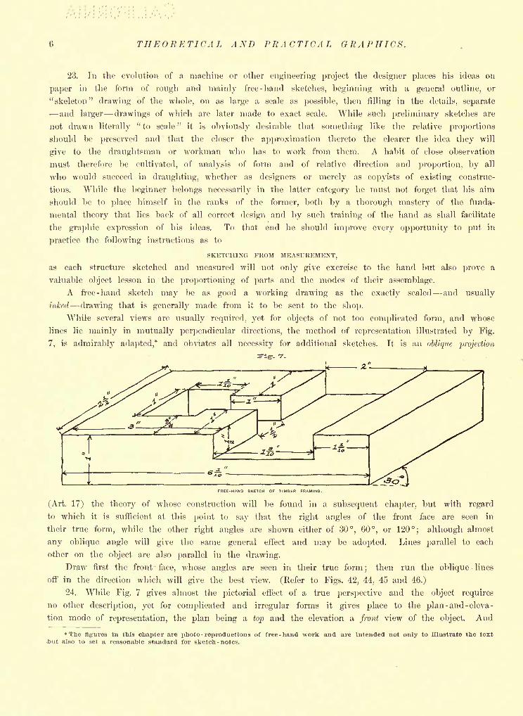
if two views are not enough for clearness as many more should be added as seem necessary, includ-
ing what are called sections, which represent the object as if cut apart by a plane, separated and a
view obtained perpendicular to the cutting plane, showing the internal arrangement and shape of parts.
In Fig. 8 we have the same object as in Fig. 7, but represented by the method just mentioned.
The front view (elevation) is evidently the same in both Figs. 7 and 8, except that in the latter we
indicate by dotted lines the hidden recess which is in full sight in Fig. 7.
The view of the top is placed at the top in conformity to the now quite general practice as to
location, viz., grouping the various sketches about the elevation, so that the view of the left end is.
at the left, of the right at the right, etc.
. a.
'
THEORETICAL AND PRACTICAL GRAPHICS.
Extension lines should be drawn and the dimension given outside the drawing whenever such
course will add to the clearness. (See D' F', Fig. 8.)
An opening should always be left in the dimension line for the figures.
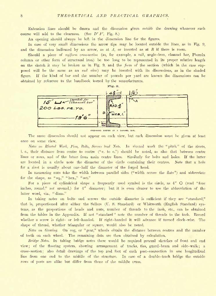
In case of very small dimensions the arrow tips may be located outside the lines, as in Fig. 9,
and the dimension indicated by an arrow, as at A, or inserted as at B if there is room.
Should a piece of uniform cross-section (as, for example, a rail, angle -iron, channel bar, Phcenix
column or other form of structural iron) be too long to be represented in its proper relative length
on the sketch it may be broken as in Fig. 9, and the form of the section (which in the case sup-
posed will be the same as an end vieio) may be inserted with its dimensions, as in the shaded
figure. If the kind of bar and the number of pounds per yard are known the dimensions can be
obtained by reference to the handbook issued by the manufacturers.
r. 9.
f <4-i
/' f$t/t/io7' /<*'"
/ ^5^ ^^/ Af^'^(C %sCt7t-fl4!-7s ias-V
2>o& L.&&. f^ft. y*&.
^s-%77
CONVENTIONAL REPRESENTATION S. FREE-HAND LETTERING.
All notes should be taken on as large a scale as possible, and so indexed that drawings of
parts may readily be understood in their relation to the whole.
The foregoing hints might be considerably extended to embrace other and special cases, but
experience will prove a sufficient teacher if the student will act on the suggestions given, and will
remember that to get an excess of data is to err on the side of safety. It need hardly be added
that what has preceded is intended to be merely a partial summary of the instructions which would
be given in the more or less brief practice in technical sketching which, presumably, constitutes a
part of every course in Graphics ;and that unless the draughtsman can be under the direction of
a teacher he will be able to sketch much more intelligently after studying more of the theory
involved in Mechanical Drawing and given in the later pages of this work.
CONVENTIONAL REPRESENTATIONS.
26. Conventional representations of the natural leatures of the country or of the materials of
construction are so called on the assumption, none too well founded, that the engineering profession
has agreed in convention that they shall indicate that which they also more or less resemble. While
there is no universal agreement in this matter there is usually but little ambiguity in their use,
especially in those that are drawn free-hand, since in them there can be a nearer approach to the
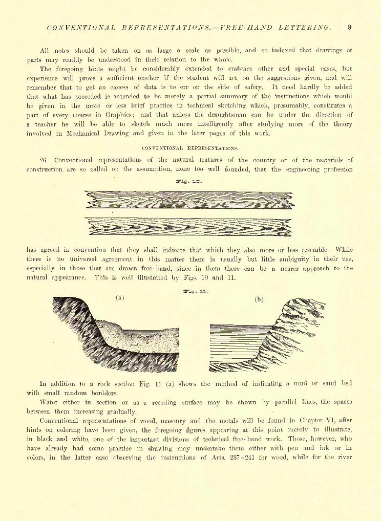
natural appearance. This is well illustrated by Figs. 10 and 11.
ii-
In addition to a rock section Fig. 11 (a) shows the method of indicating a mud or sand bed
with small random boulders.
Water either in section or as a receding surface may be shown by parallel lines, the spaces
between them increasing gradually.
Conventional representations of wood, masonry and the metals will be found in Chapter VI, after
hints on coloring have been given, the foregoing figures appearing at this point merely to illustrate,
in black and white, one of the important divisions of technical free-hand work. Those, however, who
have already had some practice in drawing may undertake them either with pen and ink or in
colors, in the latter case observing the instructions of Arts. 237-241 for wood, while for the river
10 THEORETICAL AND PRACTICAL GRAPHICS.
sections they may employ burnt umber undertone for the earthy bed, pale blue or india ink tint for
the rock, and prwsian blue for the water lines.
FREE - HAND LETTERING.
27. Although later on in this work an entire chapter is devoted to the subject of lettering, yet
at this point a word should be said regarding those forms of letters which ought to be mastered,
early in a draughting course, as the most serviceable to the practical worker.
Fig. 1.2.
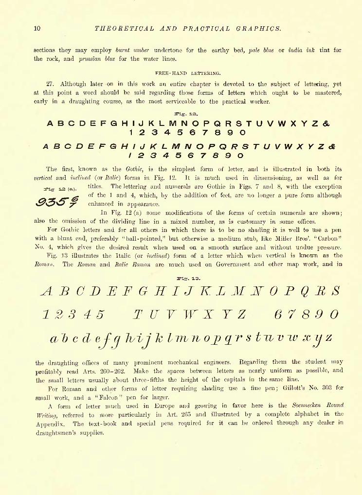
ABCDEFGHIJKLMNOPQRSTUVWXYZ&1234567890ABCDEFGHIJKLMNOPQRSTUVWXYZdi1234567890The first, known as the Gothic, is the simplest form of letter, and is illustrated in both its
vertical and inclined (or Italic) forms in Fig. 12. It is much used in dimensioning, as well as for
12 (a.)titles. The lettering and numerals are Gothic in Figs. 7 and 8, with the exception
of the 1 and 4, which, by the addition of feet, are no longer a pure form although
enhanced in appearance.
In Fig. 12 (a) some modifications of the forms of certain numerals are shown;also the omission of the dividing line in a mixed number, as is customary in some offices.
For Gothic letters and for all others in which there is to be no shading it is well to use a penwith a blunt end, preferably "ball -pointed," but otherwise a medium stub, like Miller Bros'. "Carbon"
No. 4, which gives the desired result when used on a smooth surface and without undue pressure.
Fig. 13 illustrates the Italic (or inclined) form of a letter which when vertical is known as the
Roman. The Roman and Italic Roman are much used on Government and other map work, and in
s-igr- 3-
ABCDEFGHIJKLMWOPQRS22345 T II V W X Y Z 67890a~b c d ef a Ivi/i k lirvno^ %r s t~wv
the draughting offices of many prominent mechanical engineers. Regarding them the student may
profitably read Arts. 260-262. Make the spaces between letters as nearly uniform as possible, and
the small letters usually about three -fifths the height of the capitals in the same line.
For Roman and other forms of letter requiring shading use a fine pen; Gillott's No. 303 for
small work, and a " Falcon "pen for larger.
A form of letter much used in Europe and growing in favor here is the Soennecken Round
Writing, referred to more particularly in Art. 265 and illustrated by a complete alphabet in the
Appendix. The text -book and special pens required for it can be ordered through any dealer in
draughtsmen's supplies.
THE DRAUGHTSMAN'S EQUIPMENT. 11
CHAPTER III.
DRAWING INSTRUMENTS AND MATERIALSINSTRUCTIONS AS TO USE. GENERAL PRELIMINARIES
AND TECHNICALITIES.
28. The draughtsman's equipment for graphical work should be the best con- Fig-. -3=.
sistent with his means. It is mistaken economy to buy inferior instruments.
The best obtainable will be found in the end to have been the cheapest.
The set of instruments illustrated in the following figures contains only those
which may be considered absolutely essential for the beginner.
THE DRAWING PEN.
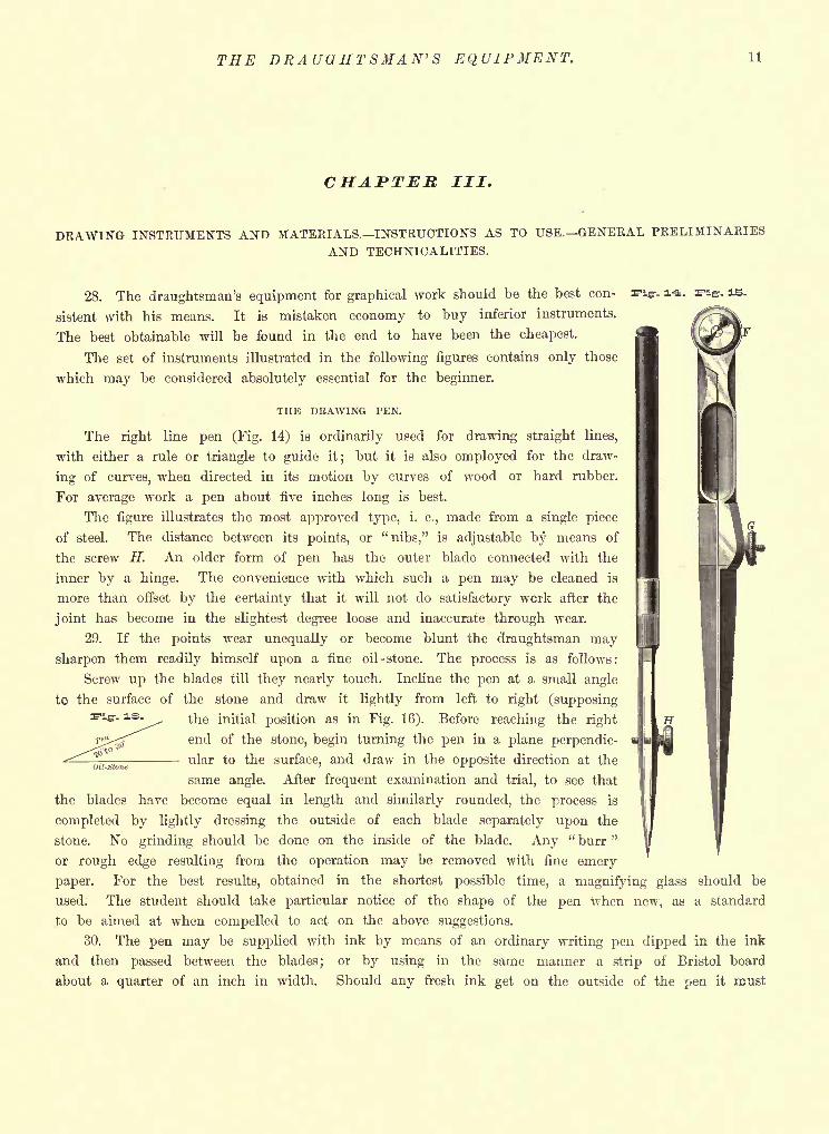
The right line pen (Fig. 14) is ordinarily used for drawing straight lines,
with either a rule or triangle to guide it; but it is also employed for the draw-
ing of curves, when directed in its motion by curves of wood or hard rubber.
For average work a pen about five inches long is best.
The figure illustrates the most approved type, i. e., made from a single piece
of steel. The distance between its points, or "nibs," is adjustable by means of
the screw H. An older form of pen has the outer blade connected with the
inner by a hinge. The convenience with which such a pen may be cleaned is
more than offset by the certainty that it will not do satisfactory work after the
joint has become in the slightest degree loose and inaccurate through wear.
29. If the points wear unequally or become blunt the draughtsman may
sharpen them readily himself upon a fine oil-stone. The process is as follows:
Screw up the blades till they nearly touch. Incline the pen at a small angle
to the surface of the stone and draw it lightly from left to right (supposing
the initial position as in Fig. 16). Before reaching the right || If
. is.
-. is.
end of the stone, begin turning the pen in a plane perpendic-- ular to the surface, and draw in the opposite direction at the
same angle. After frequent examination and trial, to see that
the blades have become equal in length and similarly rounded, the process is
completed by lightly dressing the outside of each blade separately upon the
stone. No grinding should be done on the inside of the blade. Any" burr "
or rough edge resulting from the operation may be removed with fine emery
paper. For the best results, obtained in the shortest possible time, a magnifying glass should be
used. The student should take particular notice of the shape of the pen Avhen new, as a standard
to be aimed at when compelled to act on the above suggestions.
30. The pen may be supplied with ink by means of an ordinary writing pen dipped in the ink
and then passed between the blades; or by using in the same manner a strip of Bristol board
about a quarter of an inch in width. Should any fresh ink get on the outside of the pen it must
12 THEORETICAL AND PRACTICAL GRAPHICS.
be removed; otherwise it will be transferred to the edge of the rule and thence to the paper, caus-
ing a blot.
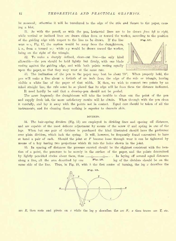
31. As with the pencil, so with the pen, horizontal lines are to be drawn from left to riyht,
while vertical or inclined lines are drawn either from or toward the worker, according to the position
of the guiding edge with respect to the line to be drawn. If the line
were m n, Fig. 17, the motion would be away from the draughtsman,
i. e., from n toward m; while op would be drawn toward the worker,
being on the right of the triangle.
32. To make a sharply defined, clean-cut line the only kind
allowable the pen should be held lightly but firmly, with one blade
resting against the guiding edge, and with both points resting equally
upon the paper, so that they may wear at the same rate.
33. The inclination of the pen to the paper may best be about 70. When properly held, the
pen will make a line about a fortieth of an inch from the edge of the rule or triangle, leaving
visible a white line of the paper of that width. If, then, we wish to connect two points by an
inked straight line, the rule must be so placed that its edge will be from them the distance indicated.
It need hardly be said that a drawing-pen should not be pushed.
The more frequently the draughtsman will take the trouble to clean out the point of the pen
and supply fresh ink, the more satisfactory results will he obtain. When through with the pen clean
it carefully, and lay it away with the points not in contact. Equal care should be taken of all the
instruments, and for cleaning them nothing is superior to chamois skin.
DIVIDERS.
34. The hair -spring dividers (Fig. 15) are employed in dividing lines and spacing off distances,
and are capable of the most delicate adjustment by means of the screw G and spring in one of the
legs. When but one pair of dividers is purchased the kind illustrated should have the preference
over plain dividers, which lack the spring. It will, however, be frequently found convenient to have
at hand a pair of each. Should the joint at F become loose through wear it can be tightened bymeans of a key having two projections which fit into the holes shown in the joint.
35. In spacing off distances the pressure exerted should be the slightest consistent with the loca-
tion of a point, the puncture to be merely in the surface of the paper, and the points determined
by lightly pencilled circles about them, thus Q . In laying off several equal distances
along a line, all the arcs described by one s>ler - ls-
leg of the dividers should be on the
same side of the line. Thus, in Fig. 19, with b the first centre of turning, the leg x describes the
arc R, then rests and pivots on c while the leg y describes the arc S; x then traces arc T, etc.
THE COMPASSES. BOW- PENCIL AND PEN. 13
COMPASS SET.
Fig-. SO. Fig- 1. Fig. 22.
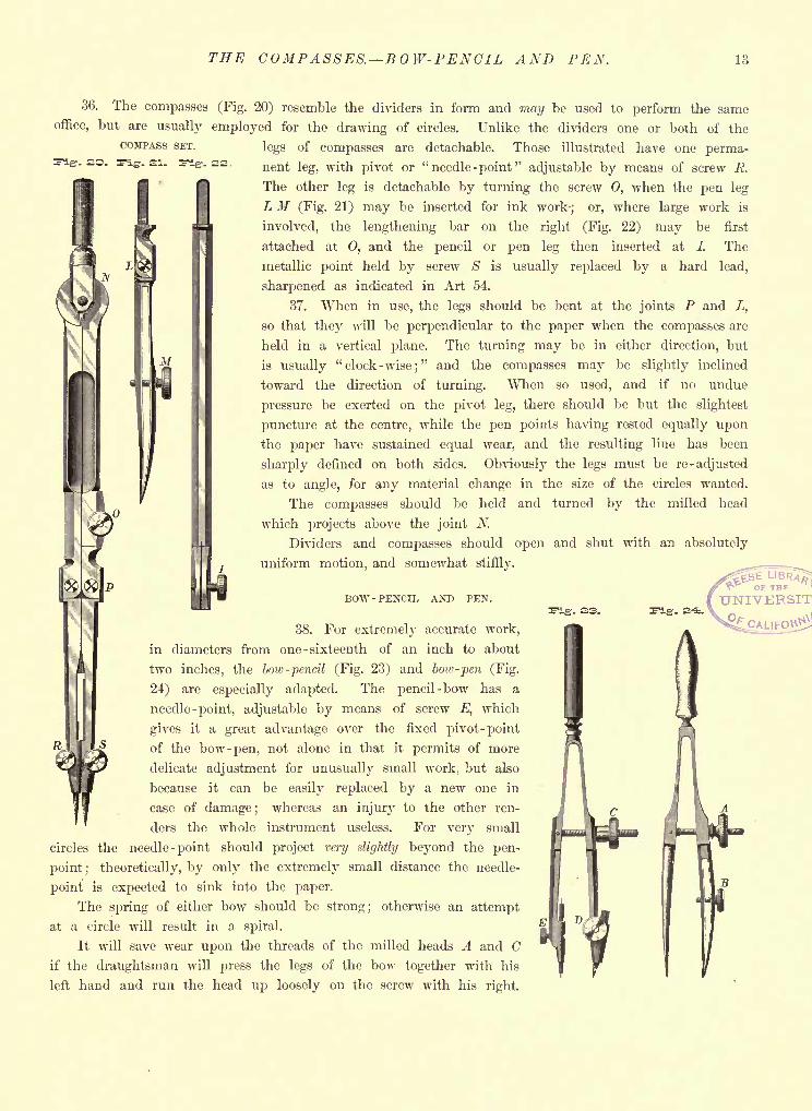
36. The compasses (Fig. 20) resemble the dividers in form and may be used to perform the same
office, but are usually employed for the drawing of circles. Unlike the dividers one or both of the
legs of compasses are detachable. Those illustrated have one perma-nent leg, with pivot or "needle -point'' adjustable by means of screw R.
The other leg is detachable by turning the screw 0, when the pen leg
L M (Fig. 21) may be inserted for ink work; or, where large work is
involved, the lengthening bar on the right (Fig. 22) may be first
attached at O, and the pencil or pen leg then inserted at /. The
metallic point held by screw S is usually replaced by a hard lead,
sharpened as indicated in Art 54.
37. When in use, the legs should be bent at the joints P and L,
so that they will be perpendicular to the paper when the compasses are
held in a vertical plane. The turning may be in either direction, but
is usually "clock-wise;" and the compasses may be slightly inclined
toward the direction of turning. When so used, and if no undue
pressure be exerted on the pivot leg, there should be but the slightest
puncture at the centre, while the pen points having rested equally upon
the paper have sustained equal wear, and the resulting line has been
sharply defined on both sides. Obviously the legs must be re -adjusted
as to angle, for any material change in the size of the circles wanted.
The compasses should be held and turned by the milled head
which projects above the joint N.
Dividers and compasses should open and shut with an absolutely
uniform motion, and somewhat stiffly.
BOW -PENCIL AND PEN.
38. For extremely accurate work,
in diameters from one -sixteenth of an inch to about
two inches, the bow -pencil (Fig. 23) and bow -pen (Fig.
24) are especially adapted. The pencil-bow has a
needle-point, adjustable by means of screw E, which
gives it a great advantage over the fixed pivot -point
of the bow -pen, not alone in that it permits of more
delicate adjustment for unusually small work, but also
because it can be easily replaced by a new one in
case of damage; whereas an injury to the other ren-
ders the whole instrument useless. For very small
circles the needle-point should project very slightly beyond the pen-
point; theoretically, by only the extremely small distance the needle-
point is expected to sink into the paper.
The spring of either bow should be strong; otherwise an attempt
at a circle will result in a spiral.
It will save wear upon the threads of the milled heads A and Cif the draughtsman will press the legs of the bow together with his
left hand and run the head up loosely on the screw with his right.
14 THEORETICAL AND PRACTICAL GRAPHICS.
39. To the above described which we may call the minimum set of instruments might be
advantageously added a pair of bow -spacers (small dividers shaped like Fig. 24) ;
beam -compasses,
for extra large circles; parallel -rule; proportional dividers, and an extra and larger right-line pen.
40. The remainder of the necessary equipment consists of paper; a drawing-board; T-rule; tri-
angles or"set squares ;
"scales
; pencils ;India ink
;water colors
;saucers for mixing ink or colors
;
brushes; water-glass and sponge; irregular (or "French") curves; india rubber; erasing knife; pro-
tractor; file for sharpening pencils, or a pad of fine emery or sand paper; thumb-tacks (or "drawing-
pins"
) ;horn centre, for making a large number of concentric circles.
PAPER AND TRACING CLOTH.
41. Drawing paper may be purchased by the sheet or roll, and either unmounted or mounted,
i. e., "backed" by muslin or heavy card-board. Smooth or "hot-pressed" paper is best for drawings
in line -work only; but the rougher surfaced, or "cold -pressed," should always be employed when
brush-work in ink or colors is involved: in the latter case, also, either mounted paper should be
used or the sheets"stretched
"by the process described in Art. 44.
42. The names and sizes of sheets are :
Cap 13 x 17 Elephant 23 x 28
Demi 15 x 20 Atlas 26 x 34
Medium 17 X 22 Columbia 23 x 35
Royal 19 x 24 Double Elephant 27 x 40
Super Royal 19 x 27 Antiquarian 31 x 53
Imperial 22 x 30
43. There are many makes of first-class papers, but the best known and still probably the most
used is Whatman's. The draughtsman's choice of paper must, however, be determined largely by the
value of the drawing to be made upon it, and by the probable usage to which it will be subjected.
Where several copies of one drawing were desired it has been a general practice to make the
original, or"construction
"drawing, with the pencil, on paper of medium grade, then to lay over
it a sheet of tracing -cloth, and copy upon it, in ink, the lines underneath. Upon placing the tracing
cloth over a sheet of sensitized paper, exposing both to the light and then immersing the sensitive
paper in water, a copy or print of the drawing was found upon the sheet, in white lines on a blue
ground the well-known blue-print. The time of the draughtsman may, however, be economized, as
also his purse, by making the original drawing in ink upon Crane's Bond paper, which combines in
a remarkable degree the qualities of transparency and toughness. About as clear blue -prints can be
made with it as with tracing-cloth, yet it will stand severe usage in the shop or the drafting -room.
Better papers may yet be manufactured for such purposes, and the progressive draughtsman will
be on the alert to avail himself of these as of all genuine improvements upon the materials and
instruments before employed.
44. To stretch paper tightly upon the board, lay the sheet right side up,* place the long rule
with its edge about one -half inch back from each edge of the paper in turn, and fold up against it
a margin of that width. Then thoroughly dampen the back of the paper with a full sponge, except
on the folded margins. Turning the paper again face up gum the margins with strong mucilage or
glue, and quickly but firmly press opposite edges down simultaneously, long sides first, exerting at the
same time a slight outward pressure with the hands to bring the paper down somewhat closer to
The "right side" of a sheet is, presumably, that toward one, when on holding it up to the light the manufacturer's
name, in water- mark, reads correctly.
TRACING-CLOTH DRAWING BOARDT-RULETRIANGLES. 15
the board. Until the gum "sets," so that the paper adheres perfectly where it should, the latter
should not shrink; hence the necessity for so completely soaking it at first. The sponge may be
applied to the face of the paper provided it is not rubbed over the surface, so as to damage it.
The stretch should be horizontal when drying, and no excess of water should be left standing on
the surface; otherwise a water-mark will form at the edge of each pool.
45. When tracing -cloth is used it must be fastened smoothly, with thumb-tacks, over the drawing
to be copied, and the ink lining done upon the glazed side, any brush work that may be required
either in ink or colors being always done upon the dull side of the cloth after the outlining has
been completed.
If the glazed surface be first dusted with powdered pipe -clay, applied with chamois skin, it will
take the ink much more readily.
When erasure is necessary use the rubber, after which the surface may be restored for further
pen -work by rubbing it with soapstone.
Tracing -cloth, like drawing paper, is most convenient to work upon if perfectly flat. When either
has been purchased by the roll it should therefore be cut in sheets, and laid away for some time in
drawers to become flat before needed for use.
DRAWING BOARD.
46. The drawing board should be slightly larger than the paper for which it is designed, and
of the most thoroughly seasoned material, preferably some soft wood, as pine, to facilitate the use of
the drawing-pins or thumb-tacks. To prevent warping it should have battens of hard wood dove-
tailed into it across the back, transversely to its length. The back of the board should be grooved
longitudinally to a depth equal to half the thickness of the wood, which weakens the board trans-
versely and to that degree facilitates the stiffening action of the battens.
For work of moderate size, on stretched paper, yet without the use of mucilage, the "panel
"
board is recommended, provided that both frame and panel are made of the best seasoned hard wood.
It will be found convenient for each student in a technical school to possess two boards, one
20" x 28" for paper of Super Royal size, which is suitable for much of a beginner's work, and another
28" X 41" for Double Elephant sheets (about twice Super Royal size), which are well adapted to large
drawings of machinery, bridges, etc. A large board may of course be used for small sheets, and the
expense of getting a second board avoided; but it is often a great convenience to have a medium-
sized board, especially in case the student desires to do some work outside the draughting -room.
THE T-RULE.
47. The T-rule should be slightly shorter than the drawing board. Its head and blade must
have absolutely straight edges, and be so rigidly combined as to admit of no lateral play of the
latter in the former. The head should also be so fastened to the blade as to be level with the surface
of the board. This permits the triangles to slide freely over the head, a great convenience when
the lines of the drawing run close to the edge of the paper. (See Fig. 32.)
The head of the T-rule should always be used along the left-hand edge of the drawing board.
TRIANGLES.
48. Triangles, or "set -squares" as they are also called, can be obtained in various materials, as
hard rubber, celluloid, pear -wood, mahogany and steel; and either solid (Fig. 25) or open (Fig. 26).
The open triangles are preferable, and two are required, one with acute angles of 30 and 60, the
other with 45 angles. Hard rubber has an advantage over metal or wood, the latter being likely
to warp and the former to rust, unless plated. Celluloid is transparent and the most cleanly of all.
16 THEORETICAL AND PRACTICAL GRAPHICS.
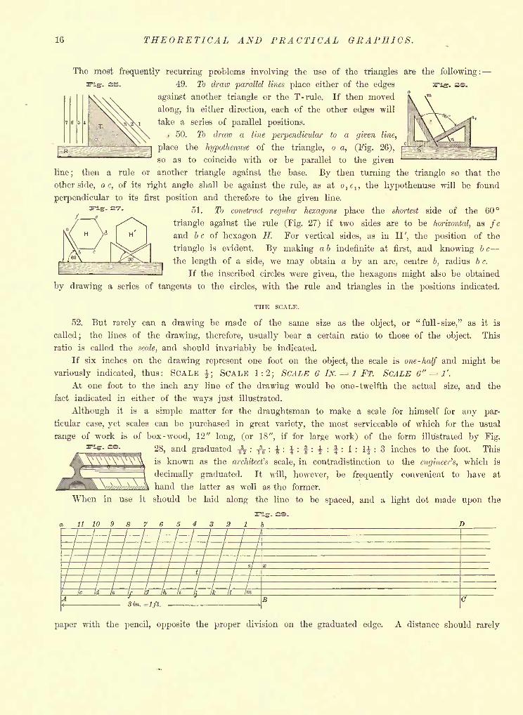
The most frequently recurring problems involving the use of the triangles are the following:
Fig. 2S.49. To draw parallel lines place either of the edges
against another triangle or the T-rule. If then moved
along, in either direction, each of the other edges will
take a series of parallel positions.
50. To draw a line perpendicular to a given line,
place the hypothenuse of the triangle, o a, (Fig. 26),
so as to coincide with or be parallel to the given
line; then a rule or another triangle against the base. By then turning the triangle so that the
other side, o c, of its right angle shall be against the rule, as at olc
l ,the hypothenuse will be found
perpendicular to its first position and therefore to the given line.
51. To construct regular hexagons place the shortest side of the 60
triangle against the rule (Fig. 27) if two sides are to be horizontal, as feH ^ I H
I and b c of hexagon H. For vertical sides, as in H', the position of the
triangle is evident. By making ab indefinite at first, and knowing be
^Lgu the length of a side, we may obtain a by an arc, centre b, radius b c.
3 If the inscribed circles were given, the hexagons might also be obtained
by drawing a series of tangents to the circles, with the rule and triangles in the positions indicated.
THE SCALE.
52. But rarely can a drawing be made of the same size as the object, or "full-size," as it is
called; the lines of the drawing, therefore, usually bear a certain ratio to those of the object. This
ratio is called the scale, and should invariably be indicated.
If six inches on the drawing represent one foot on the object, the scale is one-half and might be
variously indicated, thus: SCALE |; SCALE 1:2; SCALE 6 IN. 1 FT. SCALE 6" = !'.
At one foot to the inch any line of the drawing would be one -twelfth the actual size, and the
fact indicated in either of the ways just illustrated.
Although it is a simple matter for the draughtsman to make a scale for himself for any par-
ticular case, yet scales can be purchased in great variety, the most serviceable of which for the usual
range of work is of box-wood, 12" long, (or 18", if for large work) of the form illustrated by Fig.'- ss -
28, and graduated -fc : & : | : { : | : \ : f : 1 : \\ : 3 inches to the foot. This
is known as the architect's scale, in contradistinction to the engineer's, which is
decimally graduated. It will, however, be frequently convenient to have at
hand the latter as well as the former.
When in use it should be laid along the line to be spaced, and a light dot made upon the
a 11 10 98765432 1 b
1
SCALES. PENCILS. INKS. 17
be transferred from the scale to the drawing by the dividers, as such procedure damages the scale
if not the paper.
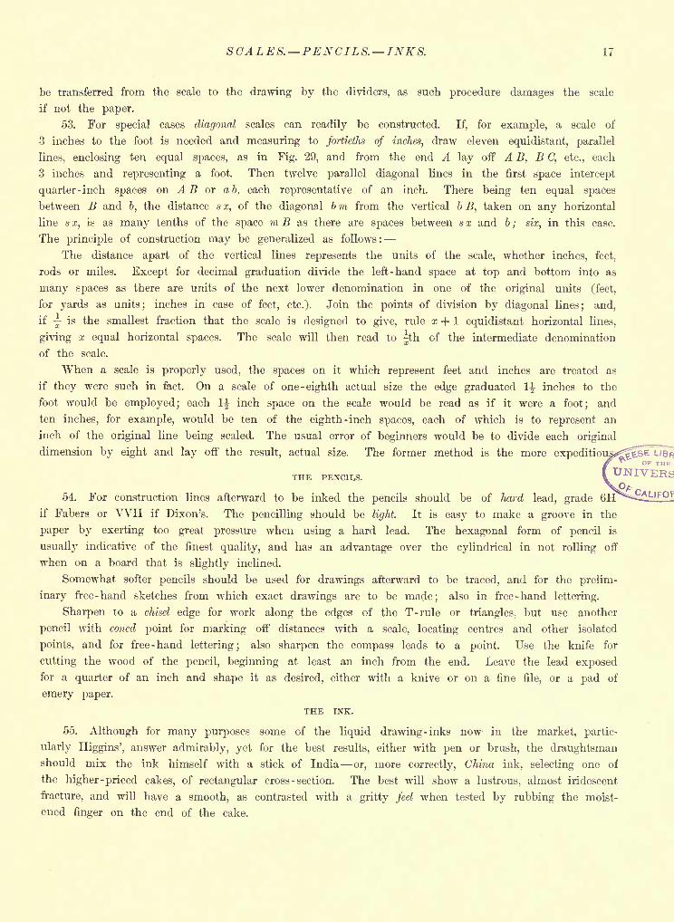
53. For special cases diagonal scales can readily be constructed. If, for example, a scale of
3 inches to the foot is needed and measuring to fortieths of inches, draw eleven equidistant, parallel
lines, enclosing ten equal spaces, as in Fig. 29, and from the end A lay off A B, B C, etc., each
3 inches and representing a foot. Then twelve parallel diagonal lines in the first space intercept
quarter -inch spaces on AB or a b, each representative of an inch. There being ten equal spaces
between B and b, the distance s x, of the diagonal b m from the vertical b B, taken on any horizontal
line s x, is as many tenths of the space m B as there are spaces between s x and b ; six, in this case.
The principle of construction may be generalized as follows:
The distance apart of the vertical lines represents the units of the scale, whether inches, feet,
rods or miles. Except for decimal graduation divide the left-hand space at top and bottom into as
many spaces as there are units of the next lower denomination in one of the original units (feet,
for yards as units; inches in case of feet, etc.). Join the points of division by diagonal lines; and,
if is the smallest fraction that the scale is designed to give, rule x + 1 equidistant horizontal lines,
giving x equal horizontal spaces. The scale will then read to jth of the intermediate denomination
of the scale.
When a scale is properly used, the spaces on it which represent feet and inches are treated as
if they were such in fact. On a scale of one -eighth actual size the edge graduated 1 inches to the
foot would be employed; each 1% inch space on the scale would be read as if it were a foot; and
ten inches, for example, would be ten of the eighth -inch spaces, each of which is to represent an
inch of the original line being scaled. The usual error of beginners would be to divide each original
dimension by eight and lay off the result, actual size. The former method is the more expedition
THE PENCILS.
54. For construction lines afterward to be inked the pencils should be of hard lead, grade
if Fabers or VVH if Dixon's. The pencilling should be light. It is easy to make a groove in the
paper by exerting too great pressure when using a hard lead. The hexagonal form of pencil is
usually indicative of the finest quality, and has an advantage over the cylindrical in not rolling off
when on a board that is slightly inclined.
Somewhat softer pencils should be used for drawings afterward to be traced, and for the prelim-
inary free-hand sketches from which exact drawings are to be made; also in free-hand lettering.
Sharpen to a chisel edge for work along the edges of the T-rule or triangles, but use another
pencil with coned point for marking off distances with a scale, locating centres and other isolated
points, and for free-hand lettering; also sharpen the compass leads to a point. Use the knife for
cutting the wood of the pencil, beginning at least an inch from the end. Leave the lead exposedfor a quarter of an inch and shape it as desired, either with a knive or on a fine file, or a pad of
emery paper.
THE INK.
55. Although for many purposes some of the liquid drawing -inks now in the market, partic-
ularly Higgins', answer admirably, yet for the best results, either with pen or brush, the draughtsmanshould mix the ink himself with a stick of India or, more correctly, China ink, selecting one of
the higher -priced cakes, of rectangular cross - section. The best will show a lustrous, almost iridescent
fracture, and will have a smooth, as contrasted with a gritty feel when tested by rubbing the moist-
ened finger on the end of the cake.
18 THEORETICAL AND PRACTICAL GRAPHICS.4
Sets of saucers, called "nests," designed for the mixing of ink and colors, form an essential part
of an equipment. There are usually six in a set, and so made that each answers as a cover for the
one below it. Placing from fifteen to twenty drops of water in one of these, the stick of ink should
be rubbed on the saucer with moderate pressure.
To properly mix ink requires great patience, as with too great pressure a mixture results having
flakes and sand -like particles of ink in it, whereas an absolutely smooth and rather thick, slow-
flowing liquid is wanted, whose surface will reflect the face like a mirror. The final test as to
sufficiency of grinding is to draw a broad line and let it dry. It should then be a rich jet black,
with a slight lustre. The end of the cake must be carefully dried on removing it from the saucer,
to prevent its flaking, which it will otherwise invariably do.
One may say, almost without qualification, and particularly when for use on tracing -cloth, the
thicker the ink the better; but if it should require thinning, on saving it from one day to another
which is possible with the close-fitting saucers described add a few drops of water, or of ox -gall if
for use on a glazed surface.
When the ink has once dried on the saucer no attempt should be made to work it up again
into solution. Clean the saucer and start anew.
WATER COLORS.
56. The ordinary colored writing inks should never be used by the draughtsman. They lack
the requisite"body
" and are corrosive to the pen. Very good colored drawing inks are now manu-
factured for line work, but Winsor and Newton's water colors, in the form called "moist," and in
"half-pans," are the best if not the most convenient, for color work either with pen or brush.
Those most frequently employed in engineering and architectural drawing are Prussian Blue, Carmine,
Light Red, Burnt Sienna, Burnt Umber, Vermilion, Gamboge, Yellow Ochre, Chrome Yellow, Payne's
Gray and Sepia. For some of their special uses see Art. 73.
Although hardly properly called a color, Chinese White may be mentioned at this point as a
requisite, and obtainable of the same form and make as the colors above.
DRAWING-PINS.
57. Drawing-pins or thumb-tacks, for fastening paper upon the board, are of various grades, the
best, and at present the cheapest, being made from a single disc of metal one -half inch in diameter,
from which a section is partially cut, then bent at right angles to the surface, forming the point of
the pin.IRREGULAR CURVES.
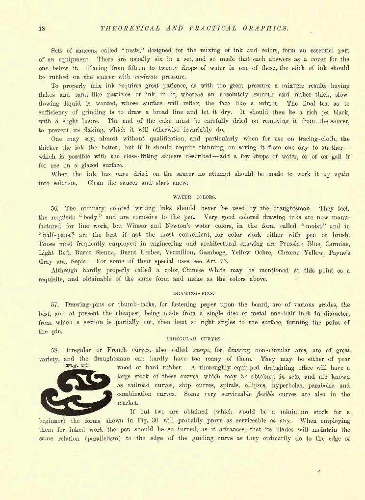
58. Irregular or French curves, also called sweeps, for drawing non- circular arcs, are of great
variety, and the draughtsman can hardly have too many of them. They may be either of pearr- so. wood or hard rubber. A thoroughly equipped draughting office will have a
large stock of these curves, which may be obtained in sets, and are known
as railroad curves, ship curves, spirals, ellipses, hyperbolas, parabolas and
combination curves. Some very serviceable flexible curves are also in the
market.
If but two are obtained (which would be a minimum stock for a
beginner) the forms shown in Fig. 30 will probably prove as serviceable as any. When employing
them for inked work the pen should be so turned, as it advances, that its blades will maintain the
same relation (parallelism) to the edge of the guiding curve as they ordinarily do to the edge of
CURVES. RUBBER. ERASERS. PROTRACTORS. BRUSHES. 19
the rule. And the student must content himself with drawing slightly less of the curve than might
apparently be made with one setting of the sweep, such course being safer in order to avoid too close
an approximation to angles in what should be a smooth curve. For the same reason, when placed
in a new position, a portion of the irregular curve must coincide with a part of that last inked.
The pencilled curve is usually drawn free-hand, after a number of the points through which it
should pass have been definitely located. In sketching a curve free-hand Ft is much more naturally
and smoothly done if the hand is always kept on the concave side of the curve.
INDIA RUBBER.
59. For erasing pencil -lines and cleaning the paper india rubber is required, that known as
"velvet
"being recommended for the former purpose, and either
"natural " or
"sponge
" rubber for
the latter. Stale bread crumbs are equally good for cleaning the surface of the paper after the lines
have been inked, but will damage pencilling to some extent.
One end of the velvet rubber may well be wedge-shaped in order to erase lines without damag-
ing others near them.
INK ERASER.
60. The double-edged erasing knife gives the quickest and best results when an inked line is to
be removed. The point should rarely be employed. The use of the knife will damage the paper
more or less, to partially obviate which rub the surface with the thumb-nail or an ivory knife
handle.
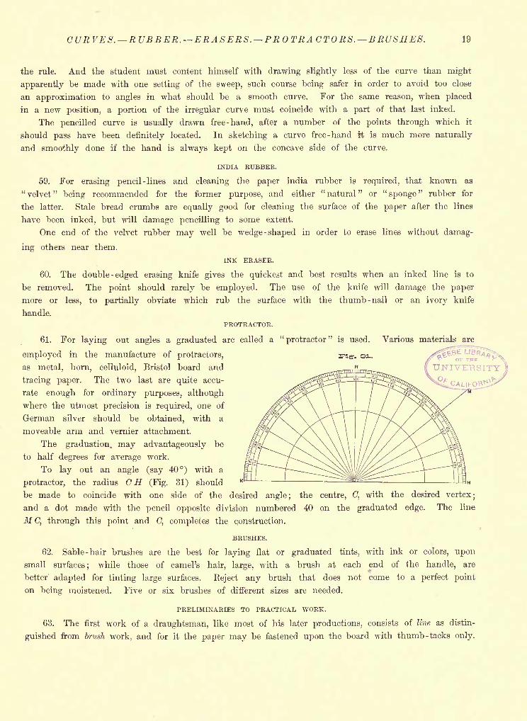
PROTRACTOR.
61. For laying out angles a graduated arc called a "protractor" is used. Various materials are
employed in the manufacture of protractors, Fig-. 31.
as metal, horn, celluloid, Bristol board and
tracing paper. The two last are quite accu-
rate enough for ordinary purposes, although
where the utmost precision is required, one of
German silver should be obtained, with a
moveable arm and vernier attachment.
The graduation, may advantageously be
to half degrees for average work.
To lay out an angle (say 40) with a
protractor, the radius CH (Fig. 31) should
be made to coincide with one side of the desired angle; the centre, C, with the desired vertex;
and a dot made with the pencil opposite division numbered 40 on the graduated edge. The line
MC, through this point and C, completes the construction.
BRUSHES.
62. Sable -hair brushes are the best for laying flat or graduated tints, with ink or colors, upon
small surfaces; while those of camel's hair, large, with a brush at each end of the handle, are
better adapted for tinting large surfaces. Reject any brush that does not come to a perfect point
on being moistened. Five or six brushes of different sizes are needed.
PRELIMINARIES TO PRACTICAL WORK.
63. The first work of a draughtsman, like most of his later productions, consists of line as distin-
guished from brush work, and for it the paper may be fastened upon the board with thumb-tacks only.
UNIVERSITY
CALIFOP
20 THEORETICAL AND PRACTICAL GRAPHICS.
There is no universal standard as to size of sheets for drawings. As a rule each draughting
office has its own set of standard sizes, and system of preserving and indexing. The columns of
the various engineering papers present frequent notes on these points, and the best system of pre-
serving and recording drawings, tracings and corrections is apparently in process of evolution. For
the student the best plan is to have all drawings of the same size bound in neat but permanentform at the end of the course. The title-pages, which presumably have also been drawn, will suf-
ficiently distinguish the different sets.
64. In his elementary work the student may to advantage adopt two sizes of sheets which are
considerably employed, 9" X 13", and its double, 13" x 18"; sizes into which a "Super Royal" sheet
naturally divides, leaving ample margins for the mucilage in case a "stretch" is to be made.
A " Double Elephant"
sheet, being twice the size of a "Super Royal," divides equally well into
plates of the above size, but is preferable on account of its better quality.
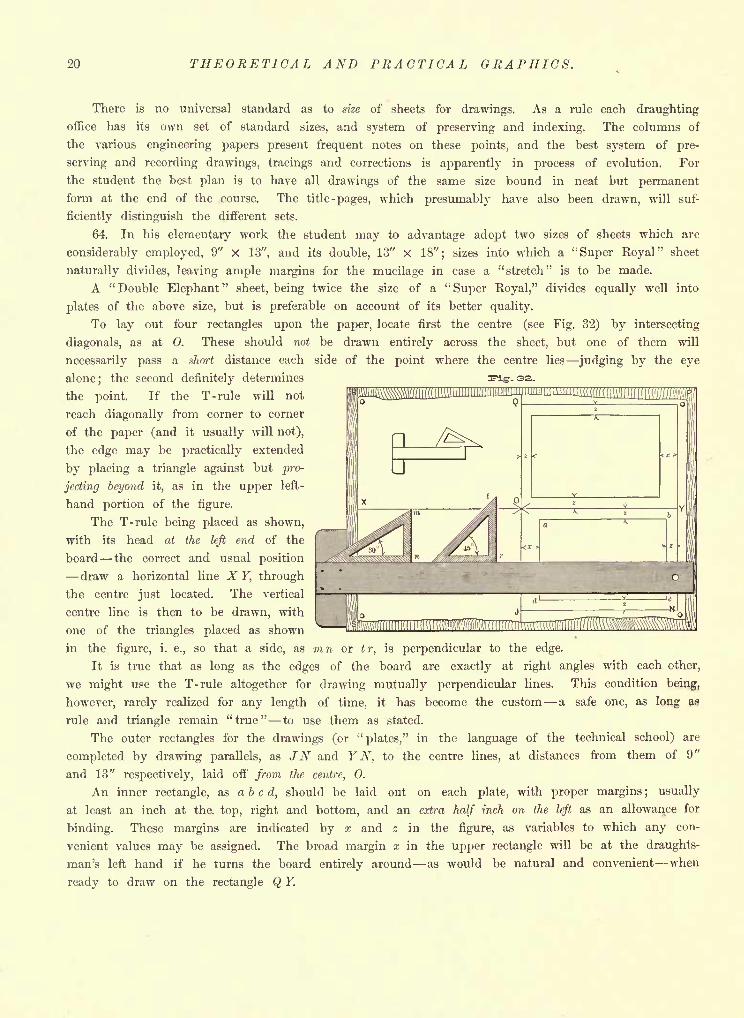
To lay out four rectangles upon the paper, locate first the centre (see Fig. 32) by intersecting
diagonals, as at 0. These should not be drawn entirely across the sheet, but one of them will
necessarily pass a short distance each side of the point where the centre lies judging by the eye
alone; the second definitely determines
the point. If the T-rule will not
reach diagonally from corner to corner
of the paper (and it usually will not),
the edge may be practically extended
by placing a triangle against but pro-
jecting beyond it, as in the upper left-
hand portion of the figure.
The T-rule being placed as shown,
with its head at the left end of the
board the correct and usual position
draw a horizontal line X Y, through
the centre just located. The vertical
centre line is then to be drawn, with
one of the triangles placed as shown
in the figure, i. e., so that a side, as mn or tr, is perpendicular to the edge.
It is true that as long as the edges of the board are exactly at right angles with each other,
we might use the T-rule altogether for drawing mutually perpendicular lines. This condition being,
however, rarely realized for any length of time, it has become the custom a safe one, as long as
rule and triangle remain "true" to use them as stated.
The outer rectangles for the drawings (or"plates," in the language of the technical school) are
completed by drawing parallels, as JN and Y N, to the centre lines, at distances from them of 9"
and 13" respectively, laid off from the centre, 0.
An inner rectangle, as abed, should be laid out on each plate, with proper margins ; usually
at least an inch at the. top, right and bottom, and an extra half inch on the left as an allowance for
binding. These margins are indicated by x and z in the figure, as variables to which any con-
venient values may be assigned. The broad margin x in the upper rectangle will be at the draughts-
man's left hand if he turns the board entirely around as would be natural and convenient when
ready to draw on the rectangle Q Y.
EXERCISES FOR PEN AND COMPASS. 21
CHAPTER IV.
GRADES OF LINES. LINE TINTING. LINE SHADING. CONVENTIONAL SECTION-LINING.
FREQUENTLY RECURRING PLANE PROBLEMS. MISCELLANEOUS PEN ANDCOMPASS EXERCISES.
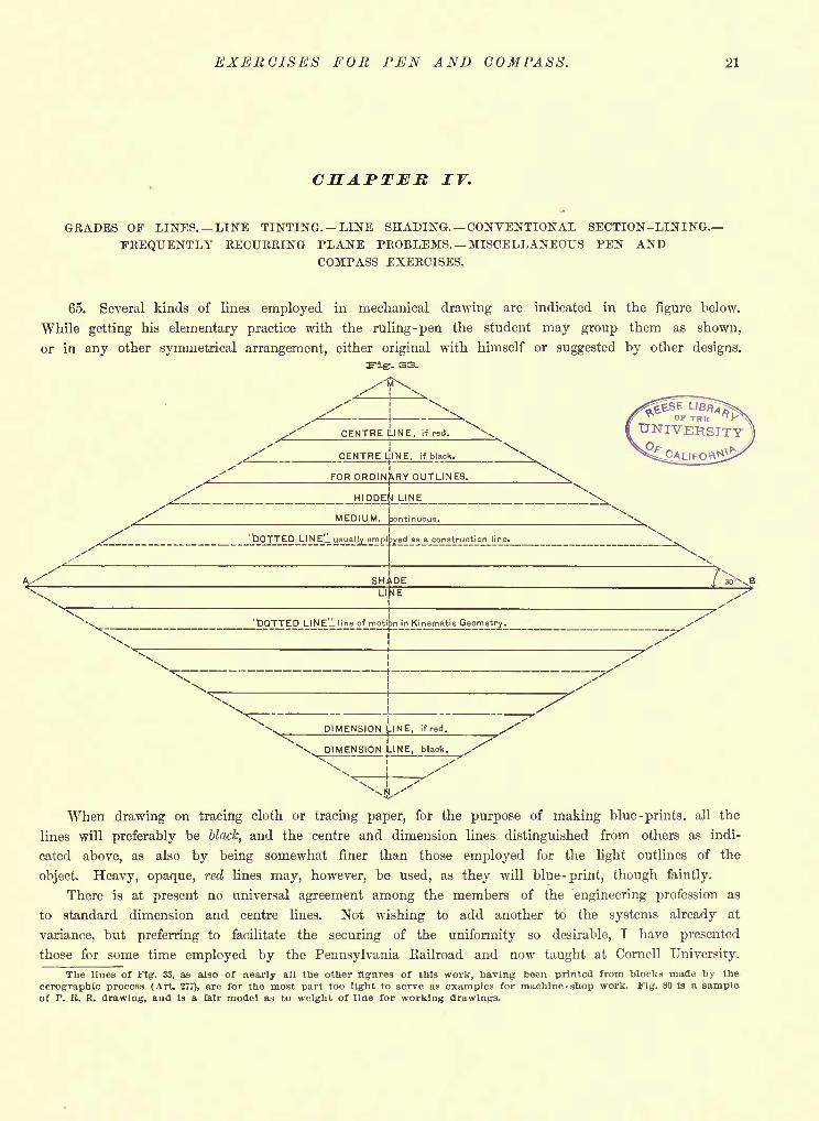
65. Several kinds of lines employed in mechanical drawing are indicated in the figure below.
While getting his elementary practice with the ruling-pen the student may group them as shown,
or in any other symmetrical arrangement, either original with himself or suggested by other designs.
Fig. 33.
FOR ORDINARY OUTLINES.
MEDIUM, Continuous.
'DO T_ED_LI N Ejl u
"^f1"^"SHADE
LlfME
/ 30^XE
"DOTTED LINE'l line of mot 3n in Kinematic Geometry.
DIMENSION
DIMENSION
.INE, ifred.
.INE, black.
When drawing on tracing cloth or tracing paper, for the purpose of making blue -prints, all the
lines will preferably be black, and the centre and dimension lines distinguished from others as indi-
cated above, as also by being somewhat finer than those employed for the light outlines of the
object. Heavy, opaque, red lines may, however, be used, as they will blue -print, though faintly.
There is at present no universal agreement among the members of the engineering profession as
to standard dimension and centre lines. Not wishing to add another to the systems already at
variance, but preferring to facilitate the securing of the uniformity so desirable, I have presented
those for some time employed by the Pennsylvania Railroad and now taught at Cornell University.
The lines of Fig. 33, as also of nearly all the other figures of this work, having been printed from blocks made by the
cerographie process (Art. 277), are for the most part too light to serve as examples for machine-shop work. Fig. 80 is a sample.of P. R. R. drawing, and is a fair model as to weight of line for working drawings.
22 THEORETICAL AND PRACTICAL GRAPHICS.
A dash-and -three -dot line (not shown in the figure) is considerably used in Descriptive Geometry,
either to represent an auxiliary plane or an invisible trace of any plane. (See Fig. 238).
The so-called "dotted" line is actually composed of short dashes. Its use as a "line of
motion " was suggested at Cornell.
When colors are used without intent to blue -print they may be drawn as light, continuous lines.
Colors will further add to the intelligibility of a drawing if employed for construction lines. Even
if red dimension lines are used, the arrow heads should invariably be black. They should be drawn
free-hand, with a writing pen, and their points touch the lines between which they give the distance.
66. The utmost accuracy is requisite in pencilling, as the draughtsman should be merely a copyist
when using the pen. On a complicated drawing even the kind of line should be indicated at the
outset, so that no time will be wasted, when inking, in the making of distinctions to which thought
has already been given during the process of construction. No unnecessary lines should be drawn,
or any exceeding of the intended limit of a line if it can possibly be avoided.
If the work is symmetrical, in whole or in part, draw centre lines first, then main outlines;and
continue the work from large parts to small.
The visible lines of an object are to be drawn first; afterward those to be indicated as concealed.
All lines of the same quality may to advantage be drawn with one setting of the pen, to ensure
uniformity; and the light outlines before the shade lines.
In drawing arcs and their tangents, ink the former first, invariably.
All the inking may best be done at once, although for the sake of clearness, in making a large
and complicated drawing, a portion usually the nearest and visible parts may be inked, the draw-
ing cleaned, and the pencilling of the construction lines of the remainder continued from that point,
The inking of the centre, dimension and construction lines naturally follows the completion of
the main design.
2|
3
|
a|
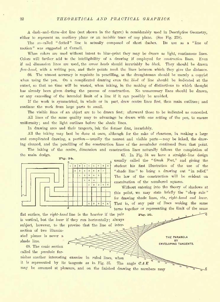
67. In Fig. 34 we have a straight-line design
usually called the" Greek Fret," and giving the
student his first illustration of the use of the
"shade line" to bring a drawing out "in relief."
The law of the construction will be evident on
examination of the numbered squares.
Without entering into the theory of shadows at
this point, we may state briefly the"shop rule "
for drawing shade lines, viz., right-hand and lower.
That is, of any pair of lines making the same
turns together or representing the limit of the same
as.flat surface, the right-hand line is the heavier if the pair
is vertical, but the lower if they run horizontally; always
subject, however, to the proviso that the line of inter-
section of two illumin-
ated planes is never a
shade line.
68. The conic section
called the parabola fur-
nishes another interesting exercise in ruled lines, whenit is represented by its tangents as in Fig. 35. The angle CAEmay be assumed at pleasure, and on the finished drawing the numbers may
THE PARABOLABY
ENVELOPING TANGENTS.
SECTION- LINING. LINE-SHADING. 23
-. OS.
be omitted, being given here merely to show the law of construction. All the divisions are equal,
and like numbers are joined.
Some interesting mathematical properties of the curve will be found in Chapter V.
69. A pleasing design that will test the beginner's skill is that of Fig. 36. It is suggestive of
a cobweb, and a skillful free-hand draughtsman could make it more realistic by adding the spider.
Use the 60 triangle for the heavy diagonals
and parallels to them; the T-rule for the hor-
izontals. Pencil the diagonals first but ink them
last.
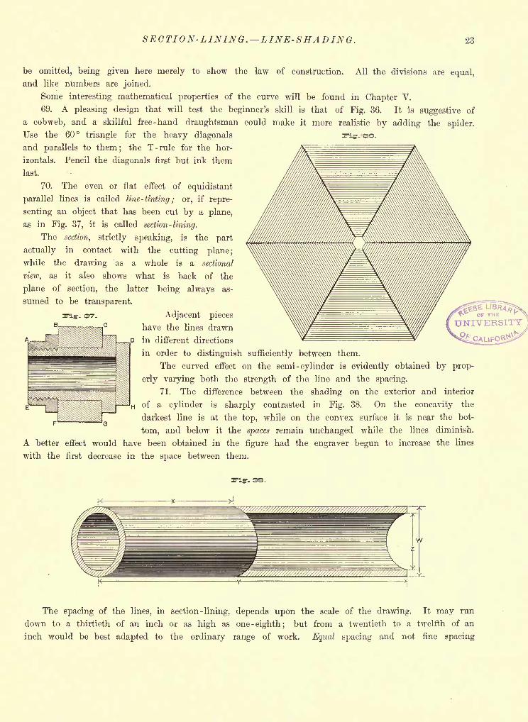
70. The even or flat effect of equidistant
parallel lines is called line -tinting ; or, if repre-
senting an object that has been cut by a plane,
as in Fig. 37, it is called section -lining.
The section, strictly speaking, is the part
actually in contact with the cutting plane;
while the drawing as a whole is a sectional
view, as it also shows what is back of the
plane of section, the latter being always as-
sumed to be transparent.
Adjacent pieces
have the lines drawn
J3 in different directions
in order to distinguish sufficiently between them.
The curved effect on the semi -cylinder is evidently obtained by prop-
erly varying both the strength of the line and the spacing.
71. The difference between the shading on the exterior and interior
H of a cylinder is sharply contrasted in Fig. 38. On the concavity the
darkest line is at the top, while on the convex surface it is near the bot-
tom, and below it the spaces remain unchanged while the lines diminish.
A better effect would have been obtained in the figure had the engraver begun to increase the lines
with the first decrease in the space between them.
- 33.
37.
w
The spacing of the lines, in section -lining, depends upon the scale of the drawing. It may run
down to a thirtieth of an inch or as high as one -eighth; but from a twentieth to a twelfth of an
inch would be best adapted to the ordinary range of work. Equal spacing and not fine spacing
24 THEORETICAL AND PRACTICAL GRAPHICS.
should be the object, and neither scale nor patent section-liner should be employed, but distances
gauged by the eye alone.
72. A refinement in execution which adds considerably to the effect is to leave a white line
between the top and left-hand outlines of each piece and the section lines. When purposing to
produce this effect, rule light pencil lines as limits for the line -tints.
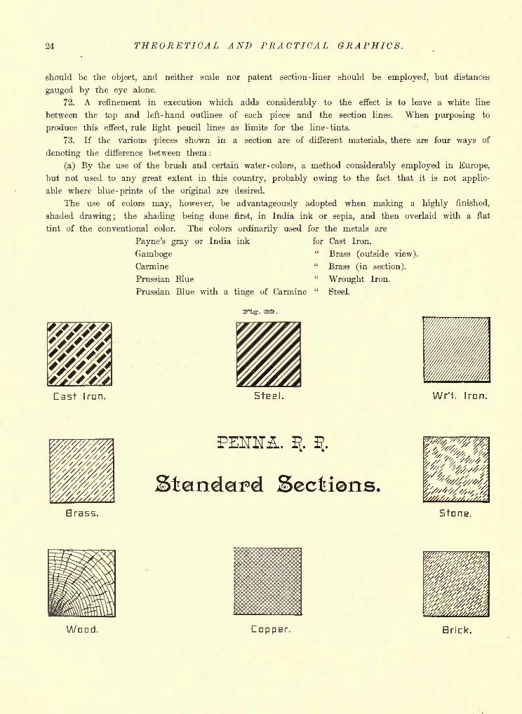
73. If the various pieces shown in a section are of different materials, there are four ways of
denoting the difference between them :
(a) By the use of the brush and certain water -colors, a method considerably employed in Europe,
but not used to any great extent in this country, probably owing to the fact that it is not applic-
able where blue -prints of the original are desired.
The use of colors may, however, be advantageously adopted when making a highly finished,
shaded drawing; the shading being done first, in India ink or sepia, and then overlaid with a flat
tint of the conventional color. The colors ordinarily used for the metals are
Payne's gray or India ink for Cast Iron.
Gamboge" Brass (outside view).
Carmine "Brass (in section).
Prussian Blue "Wrought Iron.
Prussian Blue with a tinge of Carmine "Steel.
Cast Iran. StEEl. Wr't. Iran.
Brass.
Sectiens,StnriE.
Wood. Cap PET. Brick.
CONVENTIONAL SECTION-LINING. 25
More natural effects can also be given by the use of colors, in representing the other materials
of construction; and the more of an artist the draughtsman proves to be, the closer can he approx-
imate to nature.
Pale blue may be used for water lines; Burnt Sienna, whether grained or not, suggests wood;
Burnt Umber is ordinarily employed for earth; either Light Red or Venetian Red are well adapted
for brick, and a wash of India ink having a tinge of blue gives a fair suggestion of masonry;
although the actual tint and surface of any rock can be exactly represented after a little practice
with the brush and colors. These points will be enlarged upon later.
(b) By section -lining with the drawing pen in the conventional colors just mentioned, a process
giving very handsome and thoroughly intelligible results on the original drawing, but, as before,
unadapted to blue -printing and therefore not as often used as either of the following methods.
(c) By section -lining uniformly in ink throughout, and printing the name of the material uponeach piece.
(d) By alternating light and heavy, continuous and broken
lines, according to some law. Said " law "is, unfortunately, by
no means universal, despite the attempt made at a recent con-
vention of the American Society of Mechanical Engineers to
secure uniformity. Each draughting office seems at present to
be a law unto itself in this matter.
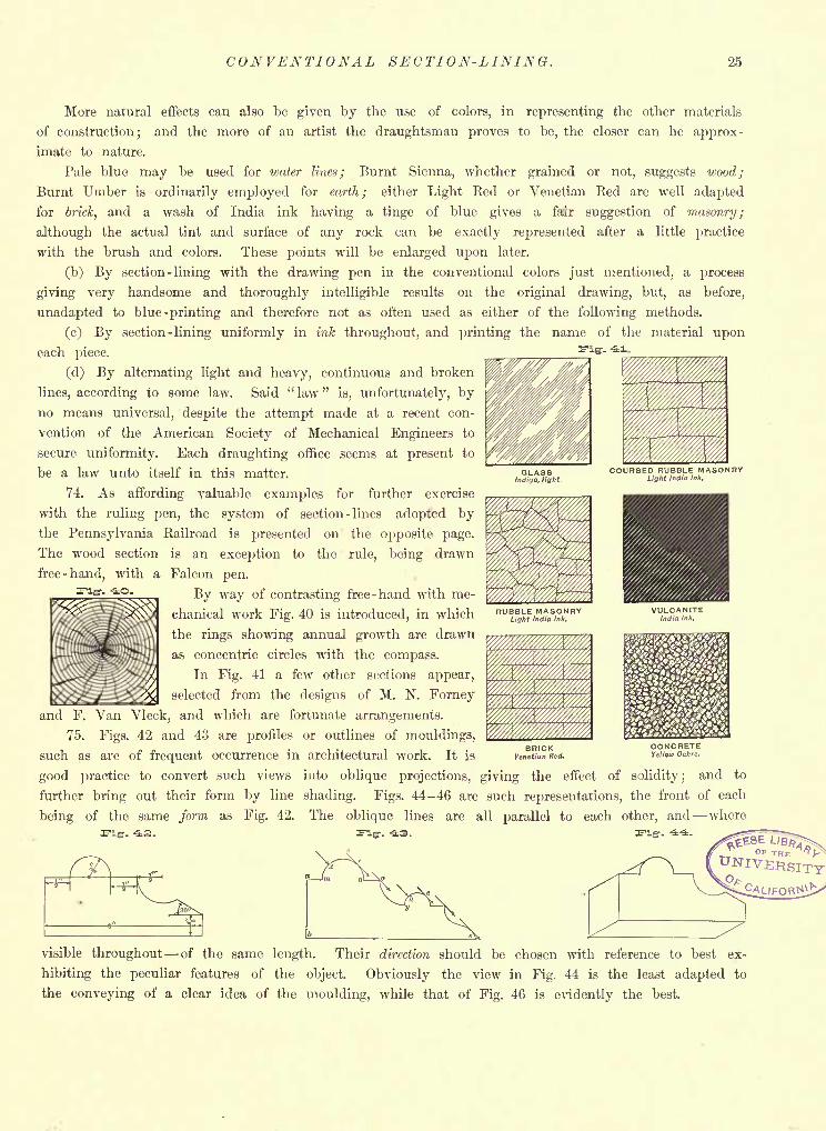
74. As affording valuable examples for further exercise
with the ruling pen, the system of section -lines adopted bythe Pennsylvania Railroad is presented on the opposite page.
The wood section is an exception to the rule, being drawn
free-hand, with a Falcon pen.
By way of contrasting free-hand with me-
chanical work Fig. 40 is introduced, in which
the rings showing annual growth are drawn
as concentric circles with the compass.
In Fig. 41 a few other sections appear,
selected from the designs of M. N. Forney
and F. Van Vleck, and which are fortunate arrangements.
75. Figs. 42 and 43 are profiles or outlines of mouldings,
such as are of frequent occurrence in architectural work. It is
good practice to convert such views into oblique projections, giving the effect of solidity; and to
further bring out their form by line shading. Figs. 44-46 are such representations, the front of each
being of the same form as Fig. 42. The oblique lines are all parallel to each other, and where
visible throughout of the same length. Their direction should be chosen with reference to best ex-
hibiting the peculiar features of the object. Obviously the view in Fig. 44 is the least adapted to
the conveying of a clear idea of the moulding, while that of Fig. 46 is evidently the best.
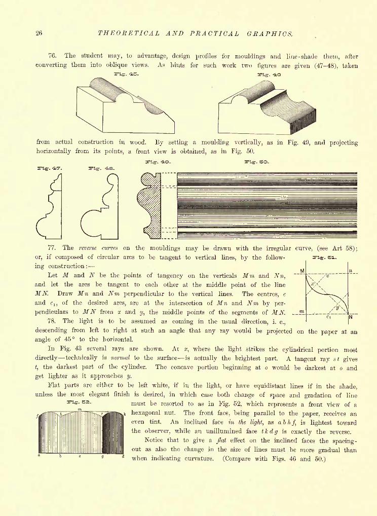
26 THEORETICAL AND PRACTICAL GRAPHICS.
76. The student may, to advantage, design profiles for mouldings and line -shade them, after
converting them into oblique views. As hints for such work two figures are given (47-48), taken
-. -US-
from actual construction in wood. By setting a moulding vertically, as in Fig. 49, and projecting
horizontally from its points, a front view is obtained, as in Fig. 50.
Flgf. -- -ie.
. SO.
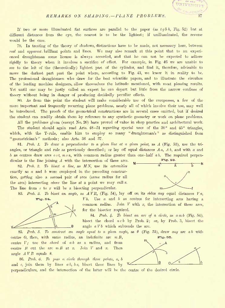
77. The reverse curves on the mouldings may be drawn with the irregular curve, (see Art 58);
r- si.
M
or, if composed of circular arcs to be tangent to vertical lines, by the follow-
ing construction :-
Let M and N be the points of tangency on the verticals Mm and Nn,and let the arcs be tangent to each other at the middle point of the line
MN. Draw Mn and Nm perpendicular to the vertical lines. The centres, c
and cn of the desired arcs, are at the intersection of Mn and Nm by per-
pendiculars to MN from x and y, the middle points of the segments of MN. SL
78. The light is to be assumed as coming in the usual direction, i. e.,
descending from left to right at such an angle that any ray would be projected on the paper at an
angle of 45 to the horizontal.
In Fig. 43 several rays are shown. At z, where the light strikes the cylindrical portion most
directly technically is normal to the surface is actually the brightest part. A tangent ray st gives
t,the darkest part of the cylinder. The concave portion beginning at o would be darkest at o and
get lighter as it approaches y.
Flat parts are either to be left white, if in the light, or have equidistant lines if in the shade,
unless the most elegant finish is desired, in which case both change of space and gradation of line
must be resorted to as in Fig. 52, which represents a front view of a
hexagonal nut. The front face, being parallel to the paper, receives an
even tint. An inclined face in the light, as abhf, is lightest toward
the observer, while an unillumined face tkdg is exactly the reverse.
Notice that to give a flat effect on the inclined faces the spacing-
out as also the change in the size of lines must be more gradual thana when indicating curvature. (Compare with Figs. 46 and 50.)
-. S2.
rr
REMARKS ON SHADING . PLANE PROBLEMS. 27
If two or more illuminated flat surfaces are parallel to the paper (as t g b h, Fig. 52) but at
different distances from the eye, the nearest is to be the lightest; if unilluminated, the reverse
would be the case.
79. In treating of the theory of shadows, distinctions have to be made, not necessary here, between
reed and apparent . brilliant points and lines. We may also remark at this point that to an experi-
enced draughtsman some license is always accorded, and that he can not be expected to adhere
rigidly to theory when it involves a sacrifice of effect. For example, in Fig. 46 we are unable to
see to the left of the (theoretically) lightest part of the cylinder, and find it, therefore, advisable to
move the darkest part past the point where, according to Fig. 43, we know it in reality to be.
The professional draughtsmen who draw for the best scientific papers, and to illustrate the circulars
of the leading machine designers, allow themselves the latitude mentioned, with most pleasing results.
Yet until one may be justly called an expert he can depart but little from the narrow confines of
theory without being in danger of producing decidedly peculiar effects.
80. As from this point the student will make considerable use of the compasses, a few of the
more important and frequently recurring plane problems, nearly all of which involve their use, may well
be introduced. The proofs of the geometrical constructions are in several cases omitted, but if desired
the student can readily obtain them by reference to any synthetic geometry or work on plane problems.
All the problems given (except No. 20) have proved of value in shop practice and architectural work.
The student should again read Arts. 48-51 regarding special uses of the 30 and 45 triangles,
which, with the T- rule, enable him to employ so many"draughtsman's
"as distinguished from
"geometrician's" methods; also Arts. 36 and 37.
81. Prob. 1. To draw a perpendicular to a given line at a given point, as A (Fig. 53), use the tri-
angles, or triangle and rule as previously described;
or lay off equal distances A a, Ab, and with a and
6 as centres draw arcs ost, msn, with common radius greater than one -half a b. The required perpen-
dicular is the line joining A with the intersection of these arcs. ^igr- 53.
82. Prob. 2. To bisect a line, as MN, use its extremities
exactly as a and 6 were employed in the preceding construc-
tion, getting also a second pair of arcs (same radius for all
the arcs) intersecting above the line at a point we may call x.
The line from s to x will be a bisecting perpendicular. m. -^^ ~~~~1
83. Prob. S. To bisect an angle, as A VB, (Fig. 54), lay off on its sides any equal distances V a,
&&- Vb. Use a and b as centres for intersecting arcs having a
common radius. Join V with x, the intersection of these arcs,
for the bisector required.
84. Prob. 4- To bisect an arc of a circle, as amb (Fig. 54),
bisect the chord a c b by Prob. 2; or, by Prob. 3, bisect the
angle a V b which subtends the arc.
85. Prob. 5. To construct an angle equal to a given angle, as 6 (Fig. 55), draw any arc a b with
centre 0, then, with same radius, an indefinite arc m B, E-IS-- SB.
centre V ; use the chord of a b as a radius, and from
centre B cut the arc m B at x. Join V and x. Then
angle AVB equals 6.
86. Prob. 6. To pass a circle through three points, a, b
and c, join them by lines a b, be, bisect these lines by
perpendiculars, and the intersection of the latter will be the centre of the desired circle.
28 THEORETICAL AND PRACTICAL GRAPHICS.
Fig. SS.
B \
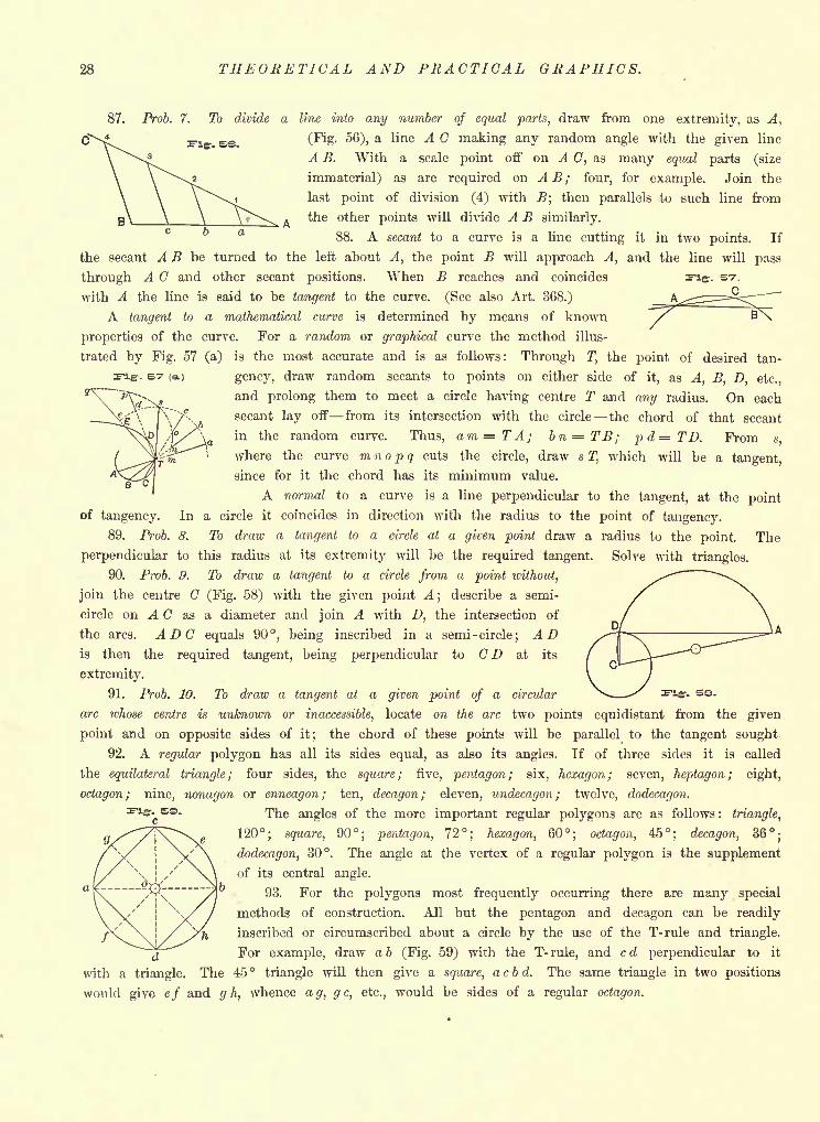
87. Prob. 7. To divide a line into any number of equal parts, draw from one extremity, as A,
(Fig. 56), a line A C making any random angle with the given line
A B. With a scale point off on A C, as many equal parts (size
immaterial) as are required on A B ; four, for example. Join the
last point of division (4) with B; then parallels to such line from
the other points will divide A B similarly.
88. A secant to a curve is a line cutting it in two points. If
the secant A B be turned to the left about A, the point B will approach A, and the line will pass
through A C and other secant positions. When B reaches and coincides E'lg-. S7.
with A the line is said to be tangent to the curve. (See also Art. 368.)
A tangent to a mathematical curve is determined by means of known
properties of the curve. For a random or graphical curve the method illus-
trated by Fig. 57 (a) is the most accurate and is as follows: Through T, the point of desired tan-
. &? (a) gency, draw random secants to points on either side ofit, as A, B, D, etc.,
and prolong them to meet a circle having centre T and any radius. On each
secant lay off from its intersection with the circle the chord of that secant
in the random curve. Thus, am=TA; bn=TB; pd=TD. From s
where the curve m n o p q cuts the circle, draw s T, which will be a tangent,
since for it the chord has its minimum value.
A normal to a curve is a line perpendicular to the tangent, at the point
of tangency. In a circle it coincides in direction with the radius to the point of tangency.
89. Prob. 8. To draw a tangent to a circle at a given point draw a radius to the point. The
perpendicular to this radius at its extremity will be the required tangent. Solve with triangles.
90. Prob. 9. To draw a tangent to a circle from a point without,
join the centre C (Fig. 58) with the given point A;
describe a semi-
circle on A C as a diameter and join A with D, the intersection of
the arcs. ADC equals 90, being inscribed in a semi -circle; ADis then the required tangent, being perpendicular to CD at its
extremity.
91. Prob. 10. To draw a tangent at a given point of a circular ^ ' ^igr- se.
arc whose centre is unknown or inaccessible, locate on the arc two points equidistant from the given
point and on opposite sides of it; the chord of these points will be parallel to the tangent sought
92. A regular polygon has all its sides equal, as also its angles. If of three sides it is called
the equilateral triangle; four sides, the square; five, pentagon; six, hexagon; seven, heptagon; eight,
octagon; nine, nonagon or enneagon; ten, decagon; eleven, undecagon ; twelve, dodecagon.
The angles of the more important regular polygons are as follows : triangle,
120; square, 90; pentagon, 72; hexagon, 60; octagon, 45; decagon, 36;dodecagon, 30. The angle at the vertex of a regular polygon is the supplement
of its central angle.
93. For the polygons most frequently occurring there are many special
methods of construction. All but the pentagon and decagon can be readily
inscribed or circumscribed about a circle by the use of the T-rule and triangle.
For example, draw a b (Fig. 59) with the T- rule, and c d perpendicular to it
with a triangle. The 45 triangle will then give a square, a c b d. The same triangle in two positions
would give ef and g h, whence ag, g c, etc., would be sides of a regular octagon.
f
PLANE PROBLEMS. 29
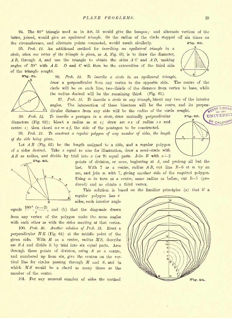
94. The 60 triangle used as in Art. 51 would give the hexagon; and alternate vertices of the
latter, joined, would give an equilateral triangle. Or the radius of the circle stepped off six times on
the circumference, and alternate points connected, would result similarly.
95. Prob. 11. An additional method for inscribing an equilateral triangle in a
circle, when one vertex of the triangle is given, as A, Fig. 60, is to draw the diameter,
A B, through A, and use the triangle to obtain the sides A and A D, making
angles of 30 with A B. D and C will then be the extremities of the third side
of the triangle sought.
96. Prob. 12. To inscribe a circle in an equilateral triangle,
draw a perpendicular from any vertex to the opposite side. The centre of the
circle will be on such line, two -thirds of the distance from vertex to base, while
the radius desired will be the remaining third. (Fig. 61).
97. Prob. IS. To inscribe a circle in any triangle, bisect any two of the interior
angles. The intersection of these bisectors will be the centre, and its perpen-
dicular distance from any side will be the radius of the circle sought.
98. Prob. 14. To inscribe a pentagon in a circle, draw mutually perpendicular
diameters (Fig. 62); bisect a radius as at s; draw arc a a; of radius sa and
centre s; then chord ax=af, the side of the pentagon to be constructed.
99. Prob. 15. To construct a regular polygon of any number of sides, the length
of the side being given.
Let A B (Fig. 63) be the length assigned to a side, and a regular polygon
of x sides desired. Take x equal to nine for illustration, draw a semi -circle with
A B as radius, and divide by trial into x (or 9) equal parts. Join B with x 2
points of division, or seven, beginning at A, and prolong all but the
last. With 7 as a centre, radius A B, cut line B-6 at m by an
arc, and join m with 7, giving another side of the required polygon.
Using m in turn as a centre, same radius as before, cut B-5 (pro-
duced) and so obtain a third vertex.
This solution is based on the familiar principles (a) that if a
regular polygon has x
sides, each interior angle
180 (x 2^equals -
'-,and (b) that the diagonals drawn
cc
from any vertex of the polygon make the same angles
with each other as with the sides meeting at that vertex.
100. Prob. 16. Another solution of Prob. 15. Erect a
perpendicular HR (Fig. 64) at the middle point of the
given side. With M as a centre, radius MS, describe
arc SA and divide it by trial into six equal parts. Arcs
through these points of division, using A as a centre,
and numbered up from six, give the centres on the ver-
tical line for circles passing through M and S, and in
which MS would be a chord as many times as the
number of the centre.
101. For any unusual number of sides the method ^B!^=SSS^ FIS. s-i.
,
\
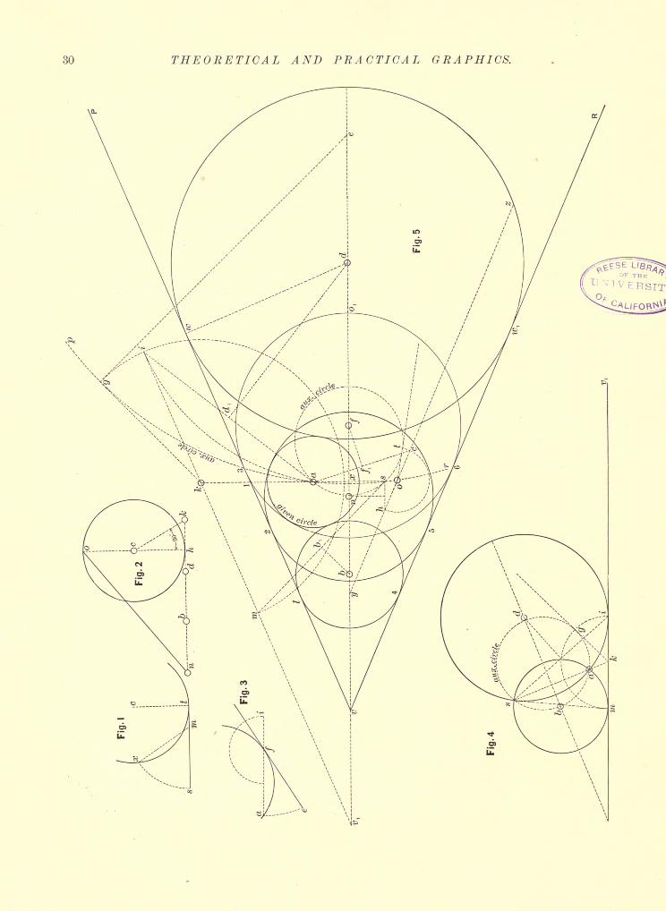
30 THEORETICAL AND PRACTICAL GRAPHICS.
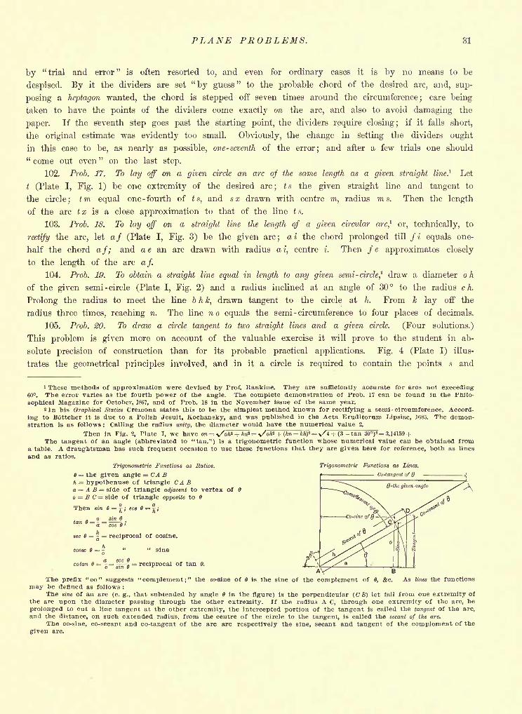
PLANE PROBLEMS. 81
by "trial and error" is often resorted to, and even for ordinary cases it is by no means to be
despised. By it the dividers are set"by guess
"to the probable chord of the desired arc, and, sup-
posing a heptagon wanted, the chord is stepped off seven times around the circumference; care being
taken to have the points of the dividers come exactly on the arc, and also to avoid damaging the
paper. If the seventh step goes past the starting point, the dividers require closing; if it falls short,
the original estimate was evidently too small. Obviously, the change in setting the dividers ought
in this case to be, as nearly as possible, one- seventh of the error; and after a few trials one should" come out even " on the last step.
102. Prob. 17. To lay off on a given circle an arc of the same length as a given straight line.1 Let
t (Plate I, Fig. 1) be one extremity of the desired arc; ts the given straight line and tangent to
the circle; tm equal one -fourth of ts, and sx drawn with centre m, radius ms. Then the length
of the arc tx is a close approximation to that of the line ts.
103. Prob. 18. To lay off on a straight line the length of a given circular arc,1
or, technically, to
rectify the arc, let af (Plate I, Fig. 3) be the given arc; ai the chord prolonged till fi equals one-
half the chord af; and ae an arc drawn with radius ai, centre i. Then fe approximates closely
to the length of the arc af.
104. Prob. 19. To obtain a straight line equal in length to any given semi- circle? draw a diameter oh
of the given semi -circle (Plate I, Fig. 2) and a radius inclined at an angle of 30 to the radius ch.
Prolong the radius to meet the line b h k, drawn tangent to the circle at h. From k lay off the
radius three times, reaching n. The line no equals the semi -circumference to four places of decimals.
105. Prob. 20. To draw a circle tangent to two straight lines and a given circle. (Four solutions.)
This problem is given more on account of the valuable exercise it will prove to the student in ab-
solute precision of construction than for its probable practical applications. Fig. 4 (Plate I) illus-
trates the geometrical principles involved, and in it a circle is required to contain the points s and
i These methods of approximation were devised by Prof. Kankine. They are sufficiently accurate for arcs not exceeding60. The error varies as the fourth power of the angle. The complete demonstration of Prob. 17 can be found in the Philo-
sophical Magazine for October, 1867, and of Prob. 18 in the November issue of the same year.*In his Graphical Statics Cremona states this to be the simplest method known for rectifying a semi-circumference. Accord-
ing to Bottcher it is due to a Polish Jesuit, Kochansky, and was published in the Acta Eruditorum Lipsiae, 1685. The demon-stration is as follows : Calling the radius unity, the diameter would have the numerical value 2.
Then In Fig. 2, Plate I, we have m = v/oA" + An = \/oW + (* khf = x/4 + (3 tan 30)2= 3.14159 +The tangent of an angle (abbreviated to "tan.") is a trigonometric function whose numerical value can be obtained from
a table. A draughtsman has such frequent occasion to use these functions that they are given here for reference, both as lines
and as ratios.
Trigonometric Functions as Ratios. Trigonometric Functions as Lines.
e = the given angle CABh = hypothenuse of triangle CABa = A B = side of triangle adjacent to vertex Ofo = B C= side of triangle opposite to fl
Cu-tangmt af Q
Then sin 9 =j ; cos
sinton 9 = 5
=
h
'
cos 6 '
sec =-J
= reciprocal of cosine.
Acosec 8 = sine
cotan 6a cos- =
ggj-g= reciprocal of tan 0.
BThe prefix "co" suggests "complement;" the co-sine of Is the sine of the complement of 6, Ac. As lines the functions
may be defined as follows :
The sine of an arc (e. g., that subtended by angle 6 in the figure) is the perpendicular (C B) let lall from one extremity of
the arc upon the diameter passing through the other extremity. If the radius A C, through one extremity of the arc, be
prolonged to cut a line tangent at the other extremity, the intercepted portion of the tangent is called the tangent of the arc,
and the distance, on such extended radius, from the centre of the circle to the tangent, Is called the secant of the arc.
The co-sine, co-secant and co-tangent of the arc are respectively the sine, secant and tangent of the complement of the
given arc.
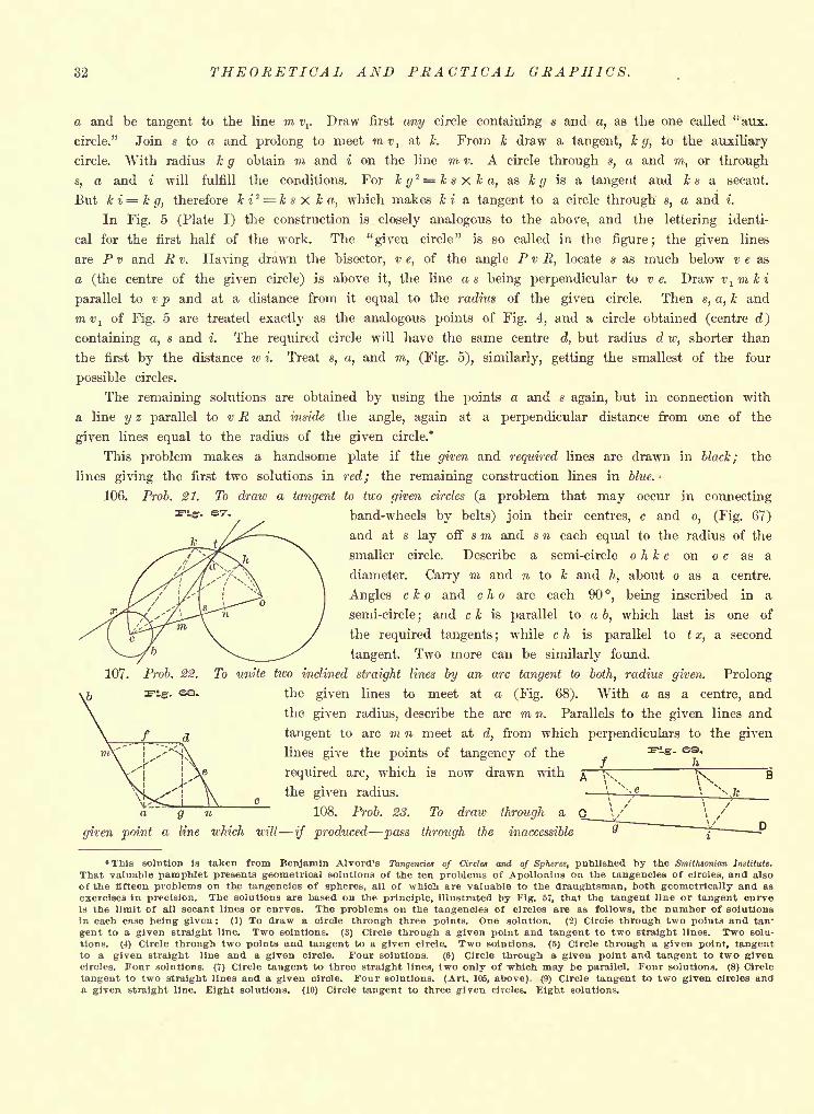
32 THEORETICAL AND PRACTICAL GRAPHICS.
a and be tangent to the line m vr Draw first any circle containing s and a, as the one called"aux.
circle." Join s to a and prolong to meet mvl
at k. From k draw a tangent, kg, to the auxiliary
circle. With radius k g obtain m and i on the line m v. A circle through s, a and m, or through
8, a and i will fulfill the conditions. For k g2 = k s x k a, as i g is a tangent and k s a secant.
But k i = k g, therefore k i2 = k s X k a, which makes k i a tangent to a circle through s, a and i.
In Fig. 5 (Plate I) the construction is closely analogous to the above, and the lettering identi-
cal for the first half of the work. The "given circle" is so called in the figure; the given lines
are P v and R v. Having drawn the bisector, v e, of the angle P v R, locate s as much below v e as
a (the centre of the given circle) is above it, the line as being perpendicular to v e. Draw vlmki
parallel to v p and at a distance from it equal to the radius of the given circle. Then s, a, k and
mvl
of Fig. 5 are treated exactly as the analogous points of Fig. 4, and a circle obtained (centre eZ)
containing a, s and i. The required circle will have the same centre d, but radius d w, shorter than
the first by the distance iv i. Treat s, a, and m, (Fig. 5), similarly, getting the smallest of the four
possible circles.
The remaining solutions are obtained by using the points a and s again, but in connection with
a line y z parallel to v R and inside the angle, again at a perpendicular distance from one of the
given lines equal to the radius of the given circle.*
This problem makes a handsome plate if the given and required lines are drawn in black; the
lines giving the first two solutions in red; the remaining construction lines in blue.
106. Prob. 21. To draw a tangent to two given circles (a problem that may occur in connecting-. &7. band-wheels by belts) join their centres, c and o, (Fig. 67)
and at s lay off s m and s n each equal to the radius of the
smaller circle. Describe a semi-circle o h k c on o c as a
diameter. Carry m and n to k and h, about o as a centre.
Angles c k o and c h o are each 90, being inscribed in a
semi-circle;and c k is parallel to a b, which last is one of
the required tangents ;while c h is parallel to t x, a second
tangent. Two more can be similarly found.
107. Prob. 22. To unite two inclined straight lines by an arc tangent to both, radius given. Prolong. s- the given lines to meet at a (Fig. 68). With a as a centre, and
the given radius, describe the arc m n. Parallels to the given lines and
tangent to arc m n meet at d, from which perpendiculars to the given
lines give the points of tangency of the
required arc, which is now drawn with
the given radius.
108. Prob. 28. To draw through a C
given point a line which will if produced pass through the inaccessible
/
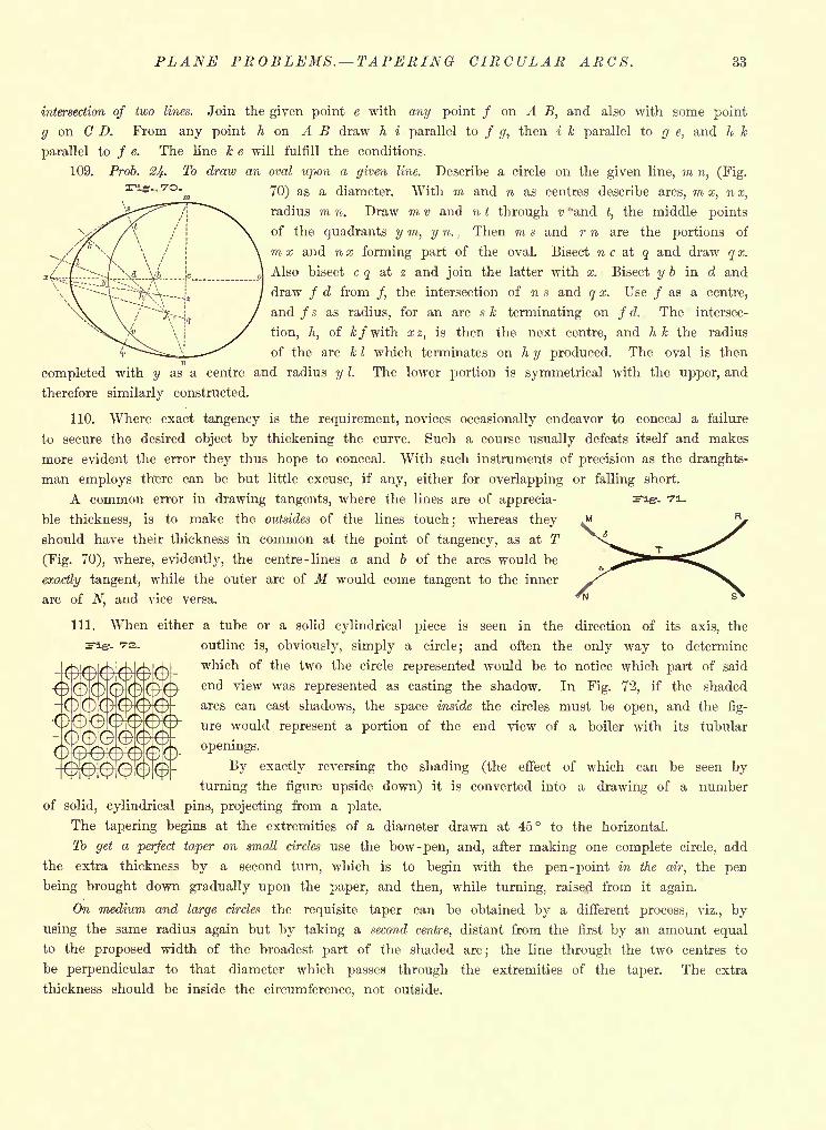
PLANE PROBLEMS. TAPERING CIRCULAR ARCS. 33
intersection of two lines. Join the given point e with any point / on A B, and also with some point
g on CD. From any point h on A B draw h i parallel to / g, then i k parallel to g e, and h k
parallel to / e. The line k e will fulfill the conditions.
109. Prob. 24- To draw an oval upon a given line. Describe a circle on the given line, m n, (Fig.
70) as a diameter. With m and n as centres describe arcs, m x, nx,
radius m n. Draw m v and n t through v ''andt,
the middle points
of the quadrants y m, y n. Then m s and r n are the portions of
7?i x and n x forming part of the oval. Bisect n c at q and draw q x.
Also bisect c q at z and join the latter with x. Bisect y b in d and
draw / d from /, the intersection of n s and q x. Use / as a centre,
and / s as radius, for an arc s k terminating on / d. The intersec-
tion, h, of kfwiih xz, is then the next centre, and h k the radius
of the arc k I which terminates on. h y produced. The oval is then
completed with y as a centre and radius y I. The lower portion is symmetrical with the upper, and
therefore similarly constructed.
110. Where exact tangency is the requirement, novices occasionally endeavor to conceal a failure
to secure the desired object by thickening the curve. Such a course usually defeats itself and makes
more evident the error they thus hope to conceal. With such instruments of precision as the draughts-
man employs there can be but little excuse, if any, either for overlapping or falling short.
A common error in drawing tangents, where the lines are of apprecia- Fig-, n.
ble thickness, is to make the outsides of the lines touch;
whereas they
should have their thickness in common at the point of tangency, as at T
(Fig. 70), where, evidently, the centre-lines a and b of the arcs would be
exactly tangent, while the outer arc of M would come tangent to the inner
arc of N, and vice versa.
111. When either a tube or a solid cylindrical piece is seen in the direction of its axis, the
s-ig-. 72. outline is, obviously, simply a circle; and often the only way to determine
which of the two the circle represented would be to notice which part of said
^000i^0f^ end view was represented as casting the shadow. In Fig. 72, if the shaded
arcs can cast shadows, the space inside the circles must be open, and the fig-
ure would represent a portion of the end view of a boiler with its tubular
openings.
OOO^^OO- ^ exactly reversing the shading (the effect of which can be seen by
turning the figure upside down) it is converted into a drawing of a number
of solid, cylindrical pins, projecting from a plate.
The tapering begins at the extremities of a diameter drawn at 45 to the horizontal.
To get a perfect taper on small circles use the bow -pen, and, after making one complete circle, add
the extra thickness by a second turn, which is to begin with the pen -point in the air, the pen
being brought down gradually upon the paper, and then, while turning, raised from it again.
On medium and large circles the requisite taper can be obtained by a different process, viz., by
using the same radius again but by taking a second centre, distant from the first by an amount equal
to the proposed width of the broadest part of the shaded arc; the line through the two centres to
be perpendicular to that diameter which passes through the extremities of the taper. The extra
thickness should be inside the circumference, not outside.
eeoooe
eeoeoeeeeo
eeo
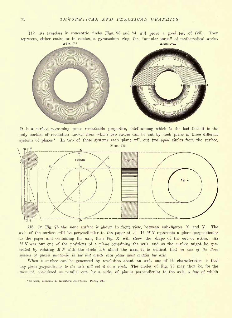
34 THEORETICAL AND PRACTICAL GRAPHICS.
112. As exercises in concentric circles Figs. 73 and 74 will prove a good test of skill. They
represent, either entire or in section, a gymnasium ring, the "annular torus" of mathematical works.
F1&. 73. Fig- 7-^.
It is a surface possessing some remarkable properties, chief among which is the fact that it is the
only surface of revolution known from which two circles can he cut by each plane in three different
systems of planes.* In two of these systems each plane will cut two equal circles from the surface.
Fig. 75.
113. In Fig. 75 the same surface is shown in front view, between sub -figures X and Y. The
axis of the surface will be perpendicular to the paper at A. If MN represents a plane perpendicular
to the paper and containing the axis, then Fig. X will show the shape of the cut or section. As
MN was but one of the positions of a plane containing the axis, and as the surface might be gen-
erated by rotating MN with the circle a b about the axis, it is evident that in one of the three
systems of planes mentioned in the last article each plane must contain the axis.
When a surface can be generated by revolution about an axis one of its characteristics is that
any plane perpendicular to the axis will cut it in a circle. The circles of Fig. 73 may then be, for the
moment, considered as parallel cuts by a series of planes perpendicular to the axis, a few of which
*Olivier, Memoires de GSomitrie Descriptive. Paris, 1851.
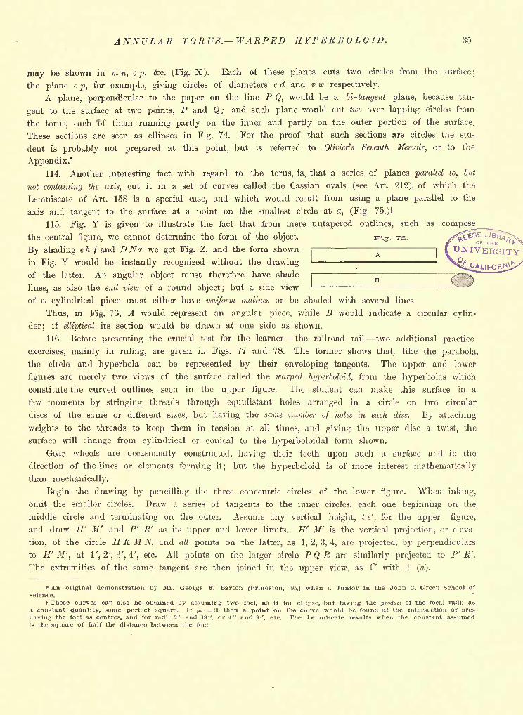
ANNULAR TORUS. WARPED HYPERBOLOID. 35
may be shown in m n, o p, &c. (Fig. X ). Each of these planes cuts two circles from the surface;
the plane o p, for example, giving circles of diameters c d and v w respectively.
A plane, perpendicular to the paper on the line P Q, would be a bi- tangent plane, because tan-
gent to the surface at two points, P and Q; and such plane would cut two over -lapping circles from
the torus, each W them running partly on the inner and partly on the outer portion of the surface.
These sections are seen as ellipses in Fig. 74. For the proof that such sections are circles the stu-
dent is probably not prepared at this point, but is referred to Olivier's Seventh Memoir, or to the
Appendix.*
114. Another interesting fact with regard to the torus, is, that a series of planes parallel to, but
not containing the axis, cut it in a set of curves called the Cassian ovals (see Art. 212), of which the
Lemniscate of Art. 158 is a special case, and which would result from using a plane parallel to the
axis and tangent to the surface at a point on the smallest circle at a, (Fig. 75.)t
115. Fig. Y is given to illustrate the fact that from mere untapered outlines, such as compose
the central figure, we cannot determine the form of the object. s^ig. 7s.
By shading eh /and DNr we get Fig. Z, and the form shown
in Fig. Y would be instantly recognized without the drawing
of the latter. An angular object must therefore have shade
lines, as also the end view of a round object; but a side view
of a cylindrical piece must either have uniform outlines or be shaded with several lines.
Thus, in Fig. 76, A would represent an angular piece, while B would indicate a circular cylin-
der; if elliptical its section would be drawn at one side as shown.
116. Before presenting the crucial test for the learner the railroad rail two additional practice
exercises, mainly in ruling, are given in Figs. 77 and 78. The former shows that, like the parabola,
the circle and hyperbola can be represented by their enveloping tangents. The upper and lower
figures are merely two views of the surface called the warped hyperboloid, from the hyperbolas which
constitute the curved outlines seen in the upper figure. The student can make this surface in a
few moments by stringing threads through equidistant holes arranged in a circle on two circular
discs of the same or different sizes, but having the same number of holes in each disc. By attaching
weights to the threads to keep them in tension at all times, and giving the upper disc a twist, the
surface will change from cylindrical or conical to the hyperboloidal form shown.
Gear wheels are occasionally constructed, having their teeth upon such a surface and in the
direction of the lines or elements forming it; but the hyperboloid is of more interest mathematically
than mechanically.
Begin the drawing by pencilling the three concentric circles of the lower figure. When inking,
omit the smaller circles. Draw a series of tangents to the inner circles, each one beginning on the
middle circle and terminating on the outer. Assume any vertical height, t s', for the upper figure,
and draw H' M' and P' R' as its upper and lower limits. H' M' is the vertical projection, or eleva-
tion, of the circle HKM N, and all points on the latter, as 1,2,3,4, are projected, by perpendiculars
to H' M', at 1', 2', 3', 4', etc. All points on the larger circle PQR are similarly projected to P' R'.
The extremities of the same tangent are then joined in the upper view, as 1' with 1 (a).
* An original demonstration by Mr. George F. Barton (Princeton, '95,) when a Junior in the John C. Green School of
Science.
t These curves can also be obtained by assuming two foci, as if for ellipse, but taking the product of the focal radii as
a constant quantity, some perfect square. If pp' = 36 then a point on the curve would be found at the intersection of arcs
having the foci as centres, and for radii 2" and 18", or 4" and 9", etc. The Lemniscate results when the constant assumedis the square of half the distance between the foci.
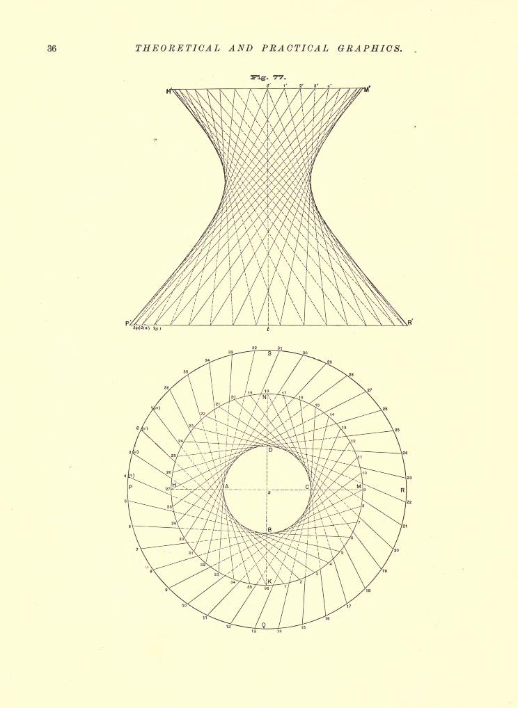
36 THEORETICAL AND PRACTICAL GRAPHICS.
13 1*
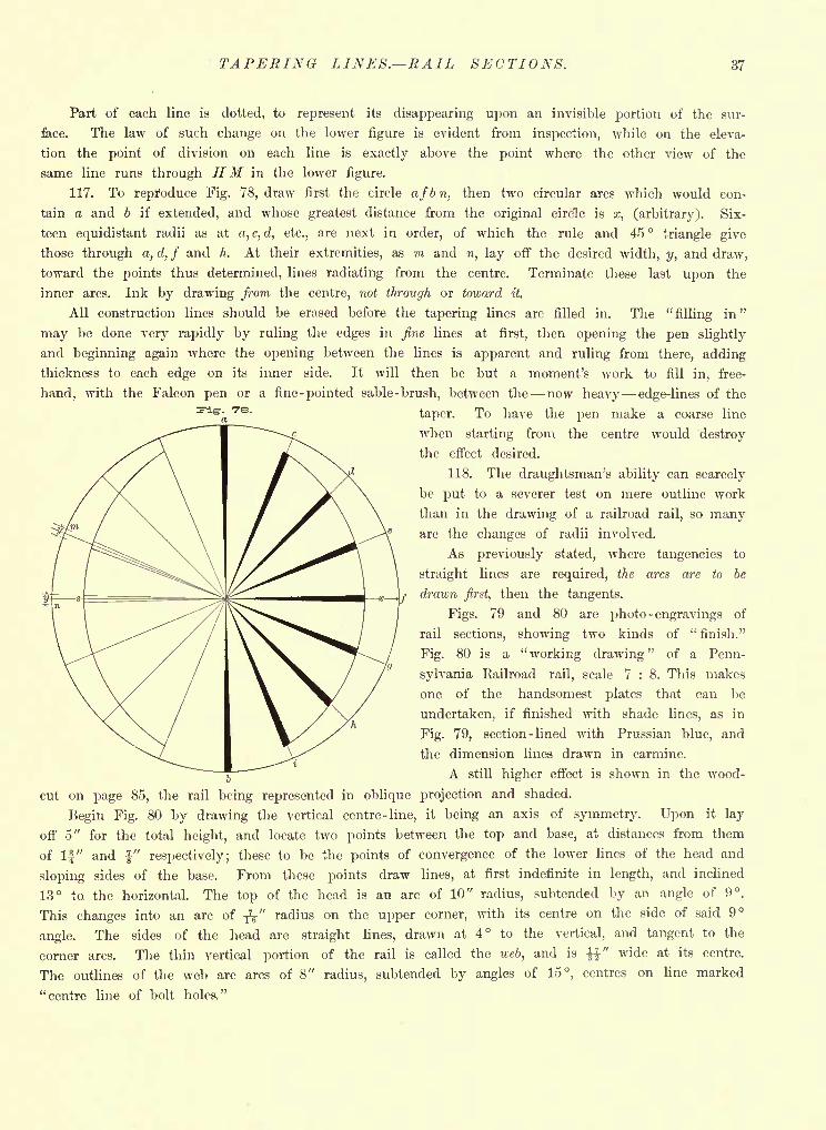
TAPERING LINES. RAIL SECTIONS. 37
Part of each line is dotted, to represent its disappearing upon an invisible portion of the sur-
face. The law of such change on the lower figure is evident from inspection, while on the eleva-
tion the point of division on each line is exactly above the point where the other view of the
same line runs through HM in the lower figure.
117. To reproduce Fig. 78, draw first the circle af b n, then two circular arcs which would con-
tain a and b if extended, and whose greatest distance from the original circle is x, (arbitrary). Six-
teen equidistant radii as at a, c, d, etc., are next in order, of which the rule and 45 triangle give
those through a, d, f and h. At their extremities, as m and n, lay off the desired width, y, and draw,
toward the points thus determined, lines radiating from the centre. Terminate these last upon the
inner arcs. Ink by drawing from the centre, not through or toward it.
All construction lines should be erased before the tapering lines are filled in. The "filling in"
may be done very rapidly by ruling the edges in fine lines at first, then opening the pen slightly
and beginning again where the opening between the lines is apparent and ruling from there, adding
thickness to each edge on its inner side. It will then be but a moment's work to fill in, free-
hand, with the Falcon pen or a fine -pointed sable -brush, between the now heavy edge-lines of the
taper. To have the pen make a coarse line
when starting from the centre would destroy
the effect desired.
118. The draughtsman's ability can scarcely
be put to a severer test on mere outline work
than in the drawing of a railroad rail, so manyare the changes of radii involved.
As previously stated, where tangencies to
straight lines are required, the arcs are to be
drawn first, then the tangents.
Figs. 79 and 80 are photo -engravings of
rail sections, showing two kinds of "finish."
Fig. 80 is a "working drawing" of a Penn-
sylvania Railroad rail, scale 7 : 8. This makes
one of the handsomest plates that can be
undertaken, if finished with shade lines, as in
Fig. 79, section - lined with Prussian blue, and
the dimension lines drawn in carmine.
A still higher effect is shown in the wood-
cut on page 85, the rail being represented in oblique projection and shaded.
Begin Fig. 80 by drawing the vertical centre-line, it being an axis of symmetry. Upon it lay
off 5" for the total height, and locate two points between the top and base, at distances from them
of If" and -J" respectively; these to be the points of convergence of the lower lines of the head and
sloping sides of the base. From these points draw lines, at first indefinite in length, and inclined
13 to. the horizontal. The top of the head is an arc of 10" radius, subtended by an angle of 9.
This changes into an arc of ^" radius on the upper corner, with its centre on the side of said 9
angle. The sides of the head are straight lines, drawn at 4 to the vertical, and tangent to the
corner arcs. The thin vertical portion of the rail is called the web, and is %%" wide at its centre.
The outlines of the web are arcs of 8" radius, subtended by angles of 15, centres on line marked
"centre line of bolt holes,"
E ' r
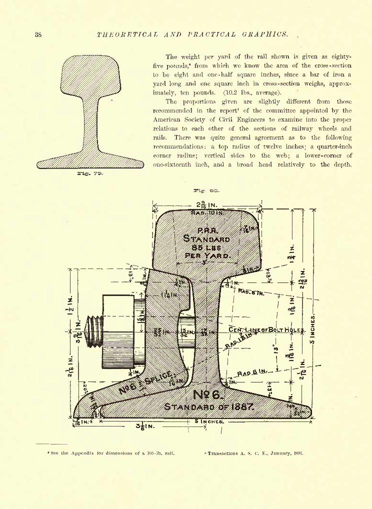
38 THEORETICAL AND PRACTICAL GRAPHICS.
The weight per yard of the rail shown is given as eighty-
five pounds,* from which we know the area of the cross -section
to be eight and one -half square inches, since a bar of iron a
yard long and one square inch in cross - section weighs, approx-
imately, ten pounds. (10.2 Ibs., average).
The proportions given are slightly different from those
recommended in the report+ of the committee appointed by the
American Society of Civil Engineers to examine into the proper
relations to each other of the sections of railway wheels and
rails. There was quite general agreement as to the following
recommendations : a top radius of twelve inches;
a quarter-inch
corner radius; vertical sides to the web; a lower -corner of
one-sixteenth inch, and a broad head relatively to the depth.
eo.
See the Appendix for dimensions of a 100-lb. rail. t Transactions A. S. C. E., January, 1891.
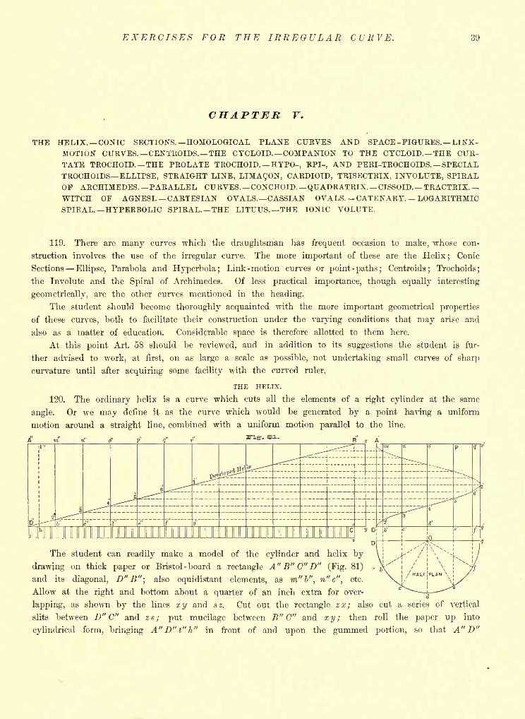
EXERCISES FOR THE IRREGULAR CURVE. 39
CHAPTER F.
THE HELIX. CONIC SECTIONS. HOMOLOGICAL PLANE CURVES AND SPACE-FIGURES. LINK-MOTION CURVES. CENTROIDS. THE CYCLOID. COMPANION TO THE CYCLOID. THE CUR-TATE TROCHOID. THE PROLATE TROCHOID. HYPO-, EPI-, AND PERI-TROCHOIDS. SPECIALTROCHOIDS ELLIPSE, STRAIGHT LINE, LIMACON, CARDIOID, TRISECTRIX, INVOLUTE, SPIRALOF ARCHIMEDES. PARALLEL CU RVES. CONCHOID. QUADRATRIX. CISSOID. TRACTRIX.
WITCH OF AGNESI. CARTESIAN OVALS. CASSIAN OVALS. CATENARY. LOGARITHMICSPIRAL. HYPERBOLIC SPIRAL. THE LITUUS. THE IONIC VOLUTE.
119. There are many curves which the draughtsman has frequent occasion to make, whose con-
struction involves the use of the irregular curve. The more important of these are the Helix;
Conic
Sections Ellipse, Parabola and Hyperbola ;Link-motion curves or point -paths; Centroids; Trochoids;
the Involute and the Spiral of Archimedes. Of less practical importance, though equally interesting
geometrically, are the other curves mentioned in the heading.
The student should become thoroughly acquainted with the more important geometrical properties
of these curves, both to facilitate their construction under the varying conditions that may arise and
also as a matter of education. Considerable space is therefore allotted to them here.
At this point Art. .58 should be reviewed, and in addition to its suggestions the student is fur-
ther advised to work, at first, on as large a scale as possible, not undertaking small curves of sharp
curvature until after acquiring some facility with the curved ruler.
THE HELIX.
120. The ordinary helix is a curve which cuts all the elements of a right cylinder at the same
angle. Or we may define it as the curve which would be generated by a point having a uniform
motion around a straight line, combined with a uniform motion parallel to the line.
fflUUUUUUUUUUUUUL
The student can readily make a model of the cylinder and helix by
drawing on thick paper or Bristol-board a rectangle A" B" C" D" (Fig. 81)
and its diagonal, D" B"; also equidistant elements, as m"b", n"c", etc.
Allow at the right and bottom about a quarter of an inch extra for over-
lapping, as shown by the lines x y and a z. Cut out the rectangle z x ; also cut a series of vertical
slits between D" C" and z.s; put mucilage between B" C" and xy; then roll the paper up into
cylindrical form, bringing A" D" t" h" in front of and upon the gummed portion, so that A" D"
40 THEORETICAL AND PRACTICAL GRAPHICS.
will coincide with B" C". The diagonal D" B" will then be a helix on the outside of the cylinder,
but half of which is visible in front view, as D'T, (see right-hand figure); the other half, T A',
being indicated as unseen.
To give the cylinder permanent form it can then be pasted to a cardboard base by mucilage on
the under side of the marginal flaps below D" C", turning them outward, not in toward the axis.
The rectangle A" B" C" D" is called the development of the cylinder; and any surface like a
cylinder or cone, which can be rolled out on a plane surface and its equivalent area obtained by
bringing consecutive elements into the same plane, is called a developable surface. The elements m"b",
n"c", etc., of the development stand vertically at b, c, d . . . . g of the half plan, and are seen in the
elevation at m'b', n'c', o' d', etc. The point 3', where any element, as c', cuts the helix, is evidently
as high as 3", where the same point appears on the development. We may therefore get the curve
D'T A' by erecting verticals from b,c,d....g, to meet horizontals from the points where the diago-
nal D" B" crosses those elements on the development. D" C" obviously equals 2 irr, where r=OD.The shortest method of drawing a helix is to divide its plan (a circle) and its pitch (D' A', the rise
in one turn) into the same number of equal parts; then verticals bm', en', etc., from the points of
division on the plan, will meet the horizontals dividing the pitch, in points 2', 3', etc., of the desired
curve.
The construction of the helix is involved in the designing of screws and screw-propellers, and in
the building of winding stairs and skew-arches.
Mathematically, both the curve and its orthographic projection are well worth study, the latter
being always a sinusoid, and becoming the companion to the cycloid for a 45-helix. (Arts. 170 and 171).
For the conical helix, seen in projection and development as a Spiral of Archimedes, see Art. 191.
THE CONIC SECTIONS.
121. 'The ellipse, parabola and hyperbola are called conic sections or conies because they may be
obtained by cutting a cone by a plane. We will, however, first obtain them by other methods.
According to the definition given by Boscovich, the ellipse, parabola and hyperbola are curves in
which there is a constant ratio between the distances of points on the curve from a certain fixed
point (the focus) and their distances from a fixed straight line (the directrix).
Referring to the parabola, Fig. 82, if S and B are points of the curve, F the focus and XY the
directrix, then, if SF:ST::BF:BX, we conclude that B and S are points of a conic section.
122. The actual value of such ratio (or eccentricity') may be 1, or either greater or less than
unity. When SF equals S T the ratio equals 1, and the relation is that of equality, or parity,
which suggests the parabola.
123. If it is farther from a point of the conic to the focus than to the directrix the ratio is
greater than 1, and the hyperbola is indicated.
124. The ellipse, of course, comes in for the third possibility as to ratio, viz., less than 1. Its
construction by this principle is not shown in Fig. 82 but later, (Art. 142), the method of generation
here given illustrating the practical way in which, in landscape gardening, an elliptical plat would be
laid out; it is therefore, called the construction as the "gardener's ellipse."
Taking A C and D E as representing the extreme length and width, the points F and Fl (foci)
would be found by cutting A C by an arc of radius equal to one -half A C, centre D. Pegs or pins
at F and F^ ,and a string, of length A C, with ends fastened at the foci, complete the preliminaries.
The curve is then traced on the ground by sliding a pointed stake against the string, as at P, so
that at all times the parts Ft P, F P, are kept straight.
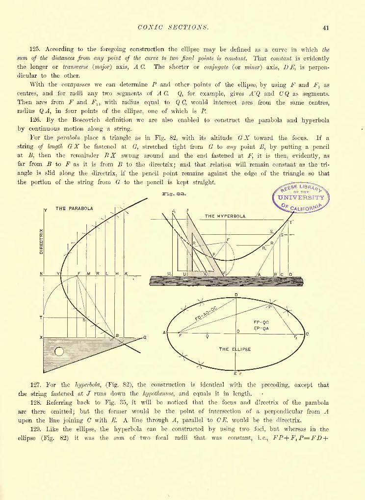
CONIC SECTIONS. 41
125. According to the foregoing construction the ellipse may be defined as a curve in which the
sum of the distances from any point of the curve to two fixed points is constant. That constant is evidently
the longer or transverse (major) axis, A C. The shorter or conjugate (or minor') axis, D E, is perpen-
dicular to the other.
With the compasses we can determine P and other points of the ellipse, by using F and F^ as
centres, and for radii any two segments of A C. Q, for example, gives A 'Q and C Q as segments.
Then arcs from F and Ft ,
with radius equal to Q C, would intersect arcs from the same centres,
radius QA, in four points of the ellipse, one of which is P.
126. By the Boscovich definition we are also enabled to construct the parabola and hyperbola
by continuous motion along a string.
For the parabola place a triangle as in Fig. 82, with its altitude GX toward the focus. If a
string of length G X be fastened at G, stretched tight from G to any point B, by putting a pencil
at B, then the remainder B X swung around and the end fastened at F, it is then, evidently, as
far from B to F as it is from B to the directrix; and that relation will remain constant as the tri-
angle is slid along the directrix, if the pencil point remains against the edge of the triangle so that
the portion of the string from G to the pencil is kept straight.
127. For the hyperbola, (Fig. 82), the construction is identical with the preceding, except that
the string fastened at / runs down the hypothenuse, and equals it in length.
128. Referring back to Fig. 35, it will be noticed that the focus and directrix of the parabola
are there omitted; but the former would be the point of intersection of a perpendicular from A
upon the line joining C with E. A line through A, parallel to C E, would be the directrix.
129. Like the ellipse, the hyperbola can be constructed by using two foci, but whereas in the
ellipse (Fig. 82) it was the sum of two focal radii that was constant, i.e., FP+F1 P^=FD+
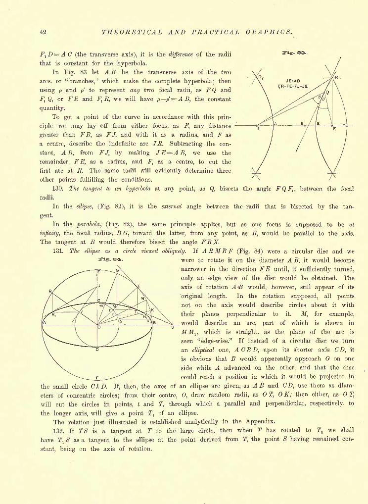
42 THEORETICAL AND PRACTICAL GRAPHICS.
FtD= A C (the transverse axis), it is the difference of the radii
that is constant for the hyperbola.
In Fig. 83 let A B be the transverse axis of the two
arcs, or "branches,1" which make the complete hyperbola; then
using p and p to represent any two focal radii, as FQ and
FI Q, or FR and F^ R, we will have p p'=A B, the constant
quantity.
To get a point of the curve in accordance with this prin-
ciple we may lay off from either focus, as F, any distance
greater than FB, as FJ, and with it as a radius, and F as
a centre, describe the indefinite arc JR. Subtracting the con-
stant, A B, from FJ, by making JE=AB, we use the
remainder, FE, as a radius, and Ft
as a centre, to cut the
first arc at R. The same radii will evidently determine three
other points fulfilling the conditions.
-. 03.
130. The tangent to an hyperbola at any point, as Q, bisects the angle FQFlt between the focal
radii.
In the ellipse, (Fig. 82), it is the external angle between the radii that is bisected by the tan-
gent.
In the parabola, (Fig. 82), the same principle applies, but as one focus is supposed to be at
infinity, the focal radius, B G, toward the latter, from any point, as B, would be parallel to the axis.
The tangent at B would therefore bisect the angle FBX.131. The ellipse as a circle viewed obliquely. If ARMBF (Fig. 84) were a circular disc and we
'- e '4 - were to rotate it on the diameter A B, it would become
narrower in the direction FE until, if sufficiently turned,
only an edge view of the disc would be obtained. The
axis of rotation A >B would, however, still appear of its
original length. In the rotation supposed, all points
not on the axis would describe circles about it with
their planes perpendicular to it. M, for example,
.would describe an arc, part of which is shown in
MMj, which is straight, as the plane of the arc is
seen "edge-wise." If instead of a circular disc we turn
an elliptical one, A CB D, upon its shorter axis CD, it
is obvious that B would apparently approach on one
side while A advanced on the other, and that the disc
could reach a position in which it would be projected in
the small circle CkD. If, then, the axes of an ellipse are given, as A B and CD, use them as diam-
eters of concentric circles; from their centre, 0, draw random radii, as T, OK; then either, as T,
will cut the circles in points, t and T, through which a parallel and perpendicular, respectively, to
the longer axis, will give a point T1
of an ellipse.
The relation just illustrated is established analytically in the Appendix.
132. If TS is a tangent at T to the large circle, then when T has rotated to T, we shall
have T, S as a tangent to the ellipse at the point derived from T, the point S having remained con-
stant, being on the axis of rotation.
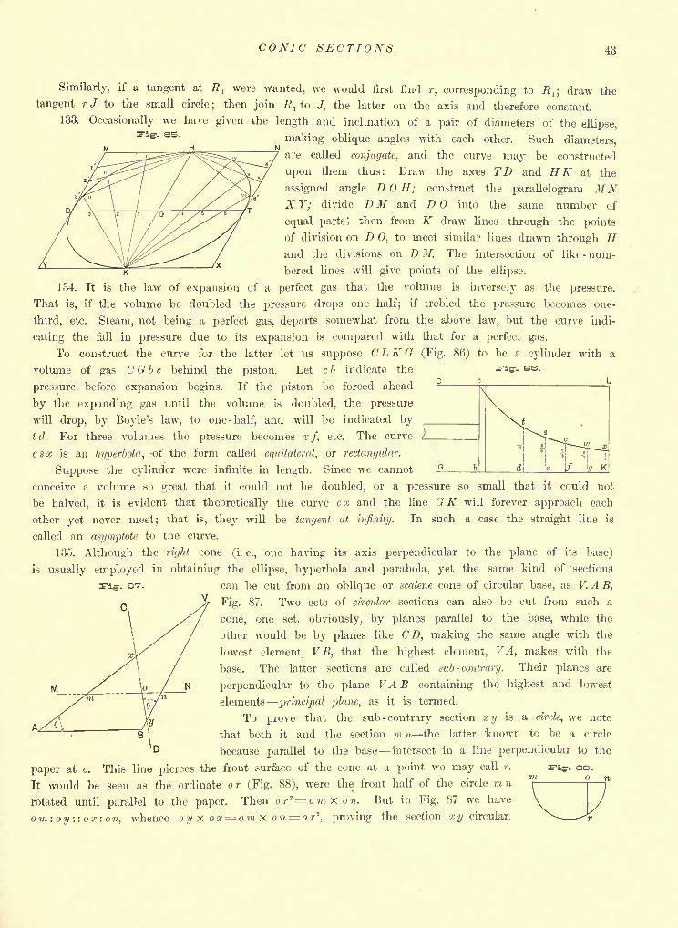
CONIC SECTIONS. 43
as.
Similarly, if a tangent at Rlwere wanted, we would first find r, corresponding to R,; draw the
tangent rJ to the small circle; then join Rlto J, the latter on the axis and therefore constant.
133. Occasionally we have given the length and inclination of a pair of diameters of the ellipse,
making oblique angles with each other. Such diameters,
are called conjugate, and the curve may be constructed
upon them thus: Draw the axies TD and HK at the
assigned angle D H; construct the parallelogram MNX Y; divide D M and D into the same number of
equal parts J then from K draw lines through the points
of division on D 0, to meet similar lines drawn through Hand the divisions on D M. The intersection of like -num-
bered lines will give points of the ellipse.
134. It is the law of expansion of a perfect gas that the volume is inversely as the pressure.
That is, if the volume be doubled the pressure drops one -half; if trebled the pressure becomes one-
third, etc. Steam, not being a perfect gas, departs somewhat from the above law, but the curve indi-
cating the fall in pressure due to its expansion is compared with that for a perfect gas.
To construct the curve for the latter let us suppose C L K G (Fig. 86) to be a cylinder with a
volume of gas C G b c behind the piston. Let c b indicate the
pressure before expansion begins. If the piston be forced ahead
by the expanding gas until the volume is doubled, the pressure
will drop, by Boyle's law, to one -half, and will be indicated by
td. For three volumes the pressure becomes v f, etc. The curve
csx is an hyperbola, -of the form called equilateral, or rectangular.
Suppose the cylinder were infinite in length. Since we cannot
conceive a volume so great that it could not be doubled, or a pressure so small that it could not
be halved, it is evident that theoretically the curve c x and the line G K will forever approach each
other yet never meet; that is, they will be tangent at infinity. In such a case the straight line is
called an asymptote to the curve.
135. Although the right cone (i. e., one having its axis perpendicular to the plane of its base)
is usually employed in obtaining the ellipse, hyperbola and parabola, yet the same kind of sections
can be cut from an oblique or scalene cone of circular base, as V. A B,
Fig. 87. Two sets of circular sections can also be cut from such a
cone, one set, obviously, by planes parallel to the base, while the
other would be by planes like CD, making the same angle with the
lowest element, V B, that the highest element, VA, makes with the
base. The latter sections are called sub -.contrary. Their planes are
perpendicular to the plane VA B containing the highest and lowest
elements principal plane, as it is termed.
To prove that the sub -contrary section x y is a circle, we note
that both it and the section m n the latter 'known to be a circle
because parallel to the base intersect in a line perpendicular to the
paper at o. This line pierces the front surface of the cone at a point we may call r.
It would be seen as the ordinate o r (Fig. 88), were the front half of the circle m n
rotated until parallel to the paper. Then or^ omxon. But in Fig. 87 we have
om:oy::or:o n, whence oy X ox= omx on or"1, proving the section x y circular.
as.o
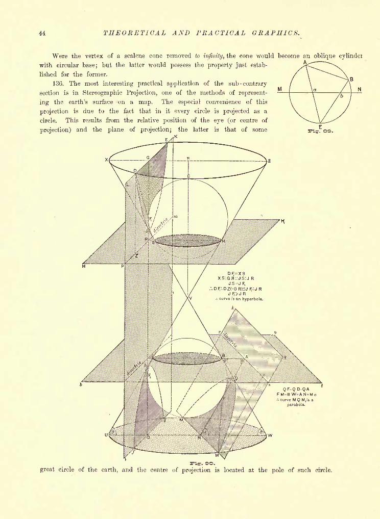
44 THEORETICAL AND PRACTICAL GRAPHICS.
M
Were the vertex of a scalene cone removed to infinity, the cone would become an oblique cylinder
with circular base; but the latter would possess the property just estab-
lished for the former.
136. The most interesting practical application of the sub -contrary
section is in Stereographic Projection, one of the methods of represent-
ing the earth's surface 'on a map. The especial convenience of this
projection is due to the fact that in it every circle is projected as a
circle. This results from the relative position of the eye (or centre of
projection) and the plane of projection; the latter is that of some
XS:G R::JS:J R^j F;
.'. Dr;:DZ(=GR)::j F;:J RJ f^>J R
.-. curve is an hyperbola.
<JF=QB=OA= B W=AN =
curve M Q Mtis a
parabola.
-. O.
great circle of the earth, and the centre of projection is located at the pole of such circle.
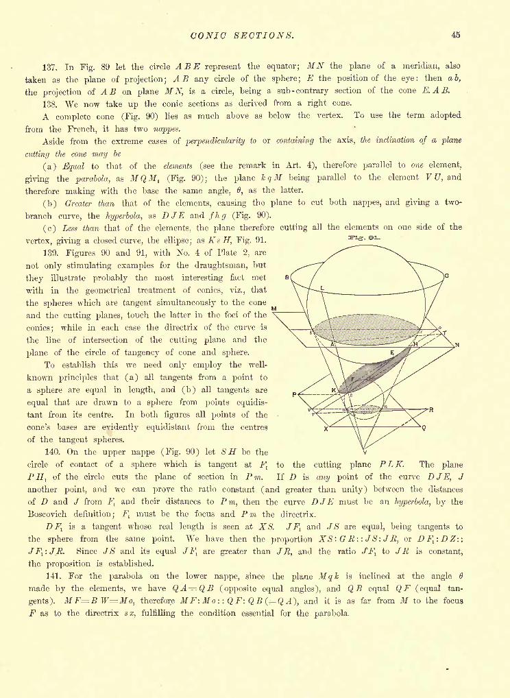
CONIC SECTIONS. 45
137. In Fig. 89 let the circle ABE represent the equator; MN the plane of a meridian, also
taken as the plane of projection; AB any circle of the sphere; E the position of the eye: then a b,
the projection of A B on plane MN, is a circle, being a sub -contrary section of the cone E.AB.
138. We now take up the conic sections as derived from a right cone.
A complete cone (Fig. 90) lies as much above as below the vertex. To use the term adopted
from the French, it has two nappes.
Aside from the extreme cases of perpendicularity to or containing the axis, the inclination of a plane
cutting the cone may be
(a) Equal to that of the elements (see the remark in Art. 4), therefore parallel to one element,
giving the parabola, as M QMl (Fig. 90) ;the plane k qM being parallel to the element V U, and
therefore making with the base the same angle, 6, as the latter.
(b) Greater than that of the elements, causing the plane to cut both nappes, and giving a two-
branch curve, the hyperbola, as DJE and fhg (Fig. 90).
(c) Less than that of the elements, the plane therefore cutting all the elements on one side of the
vertex, giving a closed curve, the ellipse; as KsH, Fig. 91.
139. Figures 90 and 91, with No. 4 of Plate 2, are
not only stimulating examples for the draughtsman, but
they illustrate probably the most interesting fact met
with in the geometrical treatment of conies, viz., that
the spheres which are tangent simultaneously to the cone
and the cutting planes, touch the latter in the foci of the
conies; while in each case the directrix of the curve is
the line of intersection of the cutting plane and the
plane of the circle of tangency of cone and sphere.
To establish this we need only employ the well-
known principles that (a) all tangents from a point to
a sphere are equal in length, and (b) all tangents are
equal that are drawn to a sphere from points equidis-
tant from its centre. In both figures all points of the
cone's bases are evidently equidistant from the centres
of the tangent spheres.
140. On the upper nappe (Fig. 90) let SH be the
circle of contact of a sphere which is tangent at F:
PHl
of the circle cuts the plane of section in Pm.
v
cutting plane P L K. The plane
any point of the curve DJE, J
to the
If D is
another point, and we can prove the ratio constant (and greater than unity) between the distances
of D and J from Fland their distances to P m, then the curve DJE must be an hyperbola, by the
Boscovich definition; Flmust be the focus and Pm the directrix.
D Fl
is a tangent whose real length is seen at XS. JFland JS are equal, being tangents to
the sphere from the same point. We have then the proportion XS: G R: : JS: J R, or DFl :DZ::
JF1
: JR. Since JS and its equal JFl
are greater than J R, and the ratio J'Flto JR is constant,
the proposition is established.
141. For the parabola on the lower nappe, since the plane Mqk is inclined at the angle 6
made by the elements, we have QA=QB (opposite equal angles), and Q equal QF (equal tan-
gents). MF=BW=Mo, therefore MF: Mo: : QF: QB( QA), and it is as far from M to the focus
F as to the directrix ax, fulfilling the condition essential for the parabola.
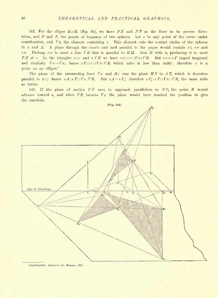
46 THEORETICAL AND PRACTICAL GRAPHICS.
142. For the ellipse KsH, (Fig. 91), we have PX and NT as the lines to be proven direc-
trices, and F and Ftthe points of tangency of two spheres. Let s be any point of the curve under
consideration, and V L the element containing s. This element cuts the contact circles of the spheres
in a and A. A plane through the cone's axis and parallel to the paper would contain ot, ov and
vn. Prolong vn to meet a line VR that is parallel to K H. Join R with a, producing it to meet
PX at r. In the triangles asr and aVR we have s a,: sr : :Va:VR. But sa sF (equal tangents)
and similarly Va=Vn; hence s F: sr : :Vn : VR, which ratio is less than unity; therefore s is a
point on an ellipse.*
The plane of the intersecting lines Va and R r cuts the plane MN in A T, which is therefore
parallel to or; hence sA : s T: :Vn :V R. But sA = sFl ;
therefore s Fl
: s T: :Vn : VR, the same ratio
as before.
143. If the plane of section PN were to approach parallelism to V C, the point R would
advance toward n, and when VR became Vn the plane would have reached the position to give
the parabola.
* Schlomilch, Geometrie des Maasses, 1874.
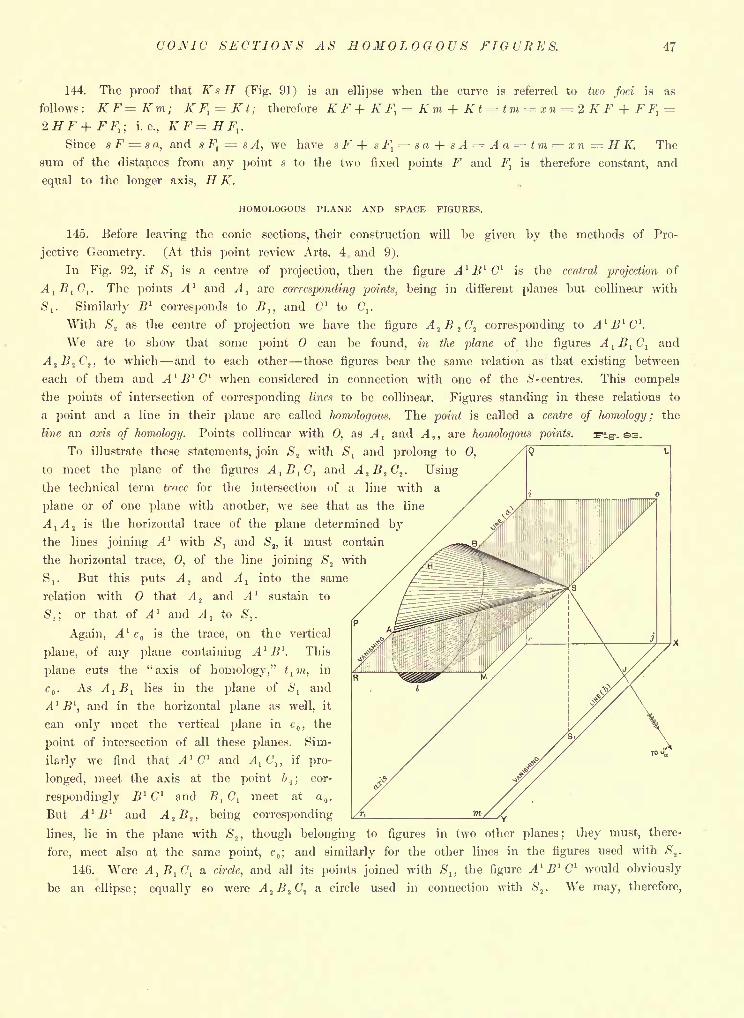
COKIC SECTIONS AS HOMOLOGOUS FIGURES. 47
144. The proof that KsH (Fig. 91) is an ellipse when, the curve is referred to tivo foci is as
follows: K F= Km; K F, = Kt; therefore K F + K Fl= Km + Kt = tm = xn =. 2 K F + F F, =
2HF+FF,; i.e., K F = H F,.
Since s F = s a, and s f\ s A, we have s F + sF1= sa + sA Aa = tm = xn=HK. The
sum of the distances from any point s to the two fixed points F and Fl
is therefore constant, and
equal to the longer axis, H K.
HOMOLOGOUS PLANE AND SPACE FIGURES.
145. Before leaving the conic sections, their construction will be given by the methods of Pro-
jective Geometry. (At this point review Arts. 4 and 9).
In Fig. 92, if Ss
is a centre of projection, then the figure A 1 B l C 1is the central projection of
AlB
l C, . The points A ' and A,
are corresponding points, being in different pianos but collinear with
6',. Similarly B l
corresponds to Bl ,
and C" to (7,.
With S, as the centre of projection we have the figure A.2B
2 C.^ corresponding to A 1 B l C 1.
We are to show that some point can be found, in the plane of the figures A1B
1C
1and
A^B,C2 ,to which and to each other those figures bear the same relation as that existing between
each of them and A 1 B 1 C 1 when considered in connection with one of the $- centres. This compels
the points of intersection of corresponding lines to be collinear. Figures standing in these relations to
a point and a line in their plane are called homologous. The point is called a centre of homology; the
line an axis of homology. Points collinear with 0, as Aland A
2 ,are homologous points. T^ig-. 3.
To illustrate these statements, join S.fwith 5, and prolong to 0,
to meet the plane of the figures A1B
1C
1and A.^B.^C^. Using
the technical term trace for the intersection of a line
plane or of one plane with another, we see that as th
AjA 2is the horizontal trace of the plane determined
the lines joining A 1 with S^ and St ,
it must contain
the horizontal trace, 0, of the line joining S.2with
S,. But this puts A2
and Al
into the same
relation with that A.^ and A 1 sustain to
S2 ;
or that of A 1 and Al
to ,.
Again, A 1c is the trace, on the vertical
plane, of any plane containing A 1 B\ This
plane cuts the "axis of homology," tl m, in
c . As A1B
llies in the plane of S
land
A 1 B l
,and in the horizontal plane as well, it
can only meet the vertical plane in c,the
point of intersection of all these planes. Sim-
ilarly we find that A 1 C 1 and AjC\, if pro-
longed, meet the axis at the point b;
cor-
respondingly B l C" and Bl C, meet at .
But A 1 B 1 and A2 B.,, being corresponding
lines, lie in the plane with <S2 , though belonging to figures in two other planes; they must, there-
fore, meet also at the same point, c;and similarly for the other lines in the figures used with <S'
2 .
146. Were A1B
1 C\ a circle, and all its points joined with Sn the figure A 1 B 1 C 1 would obviously
be an ellipse; equally so were A2B.2 C2
a circle used in connection with St
. We may, therefore,
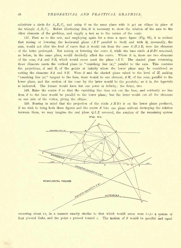
48 THEORETICAL AND PRACTICAL GRAPHICS.
substitute a circle for A1B.
tC
1 ,and using on the same plane with it get an ellipse in place of
the triangle A,B
lC
l. Before illustrating this, it is necessary to show the relation of the axis to the
other elements of the problem, and supply a test as to the nature of the conic.
147. First as to the axw, and employing again for a time a space figure (Fig. 93), it is evident
that raising or lowering the horizontal plane cX Y parallel to itself, and with it, necessarily, the
axis, would not alter the kind of curve that it would cut from the cone S. HA B, were the elements
of the latter prolonged. But raising or lowering the centre S, while the base circle AHBt remained,
as before, in the same place, would decidedly affect the curve. Where it is, there are two elements
of the cone, SA and SB, which would never meet the plane cXY. The shaded plane containing
those elements meets the vertical plane in "vanishing line (a)," parallel to the axis. This contains
the projections, A and B, of the points at infinity where the lower plane may be considered as
cutting the elements SA and SB. Were S and the shaded plane raised to the level of H, making
"vanishing line (a)" tangent to the base, there would be one element, S H, of the cone, parallel to the
lower plane, and the section of the cone by the latter would be the parabola; as it is, the hyperbola
is indicated. The former would have but one point at infinity; the latter, two.
148. Raise the centre S so that the vanishing line does not cut the base, and evidently no line
from S to the base would be parallel to the lower plane; but the latter would cut all the elements
on one side of the vertex, giving the ellipse.
149. Bearing in mind that the projection of the circle AHBt is on the lower plane produced,
if we wish to bring both these figures and the centre S into one plane without destroying the relation
between them, we may imagine the end plane QLX removed, the rotation of the remaining system
occurring about crl
in a manner exactly similar to that which would occur were iojc a system of
four pivoted links, and the point o pressed toward c. The motion of S would be parallel and equal
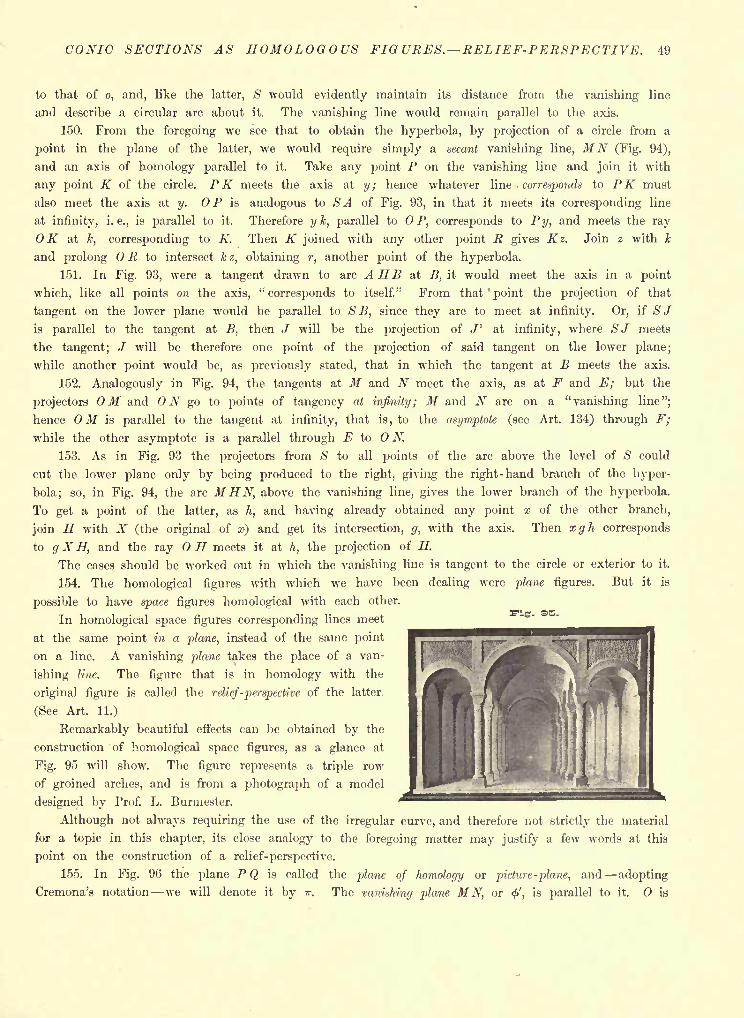
CONIC SECTIONS AS HOMOLOGOUS FIGURES. RELIEF-PERSPECTIVE. 49
to that of o, and, like the latter, S would evidently maintain its distance from the vanishing line
and describe a circular arc about it. The vanishing line would remain parallel to the axis.
150. From the foregoing we see that to obtain the hyperbola, by projection of a circle from a
point in the plane of the latter, we would require simply a secant vanishing line, MN (Fig. 94),
and an axis of homology parallel to it. Take any point P on the vanishing line and join it with
any point K of the circle. PK meets the axis at y; hence whatever line -corresponds to PK must
also meet the axis at y. OP is analogous to SA of Fig. 93, in that it meets its corresponding line
at infinity, i.e., is parallel to it. Therefore y k, parallel to OP, corresponds to Py, and meets the ray
OK at k, corresponding to K. Then K joined with any other point R gives Kz. Join z with k
and prolong R to intersect k z, obtaining r, another point of the hyperbola.
151. In Fig. 93, were a tangent drawn to arc AH B at -B, it would meet the axis in a point
which, like all points on the axis, "corresponds to itself." From that'
point the projection of that
tangent on the lower plane would be parallel to SB, since they are to meet at infinity. Or, if S Jis parallel to the tangent at B, then J will be the projection of J 1
at infinity, where SJ meets
the tangent; J will be therefore one point of the projection of said tangent on the lower plane;
while another point would be, as previously stated, that in which the tangent at B meets the axis.
152. Analogously in Fig. 94, the tangents at M and N meet the axis, as at F and E; but the
projectors OM and ON go to points of tangency at infinity; M and N are on a "vanishing line";
hence OM is parallel to the tangent at infinity, that is, to the asymptote (see Art. 134) through F;
while the other asymptote is a parallel through E to ON.
153. As in Fig. 93 the projectors from S to all points of the arc above the level of S could
cut the lower plane only by being produced to the right, giving the right-hand branch of the hyper-
bola; so, in Fig. 94, the arc MHN, above the vanishing line, gives the lower branch of the hyperbola.
To get a point of the latter, as h, and having already obtained any point x of the other branch,
join H with X (the original of a>) and get its intersection, g, with the axis. Then xgh corresponds
to g X H, and the ray H meets it at h, the projection of H.
The cases should be worked out in which the vanishing line is tangent to the circle or exterior to it.
154. The homological figures with which we have been dealing were plane figures. But it is
possible to have space figures homological with each other.
In homological space figures corresponding lines meet
at the same point in a plane, instead of the same point
on a line. A vanishing plane takes the place of a van-
ishing line. The figure that is in homology with the
original figure is called the relief-perspective of the latter.
(See Art. 11.)
Remarkably beautiful effects can be obtained by the
construction of homological space figures, as a glance at
Fig. 95 will show. The figure represents a triple row
of groined arches, and is from a photograph of a model
designed by Prof. L. Burmester.
Although not always requiring the use of the irregular curve, and therefore not strictly the material
for a topic in this chapter, its close analogy to the foregoing matter may justify a few words at this
point on the construction of a relief-perspective.
155. In Fig. 96 the plane P Q is called the plane of homology or picture -plane, and adopting
Cremona's notation we will denote it by ir. The vanishing plane MN, or <', is parallel to it. is
:, se.
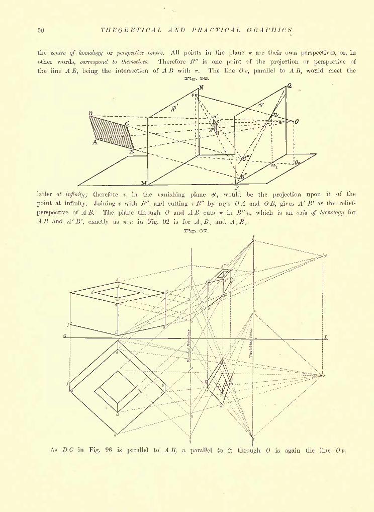
50 THEORETICAL AND PRACTICAL GRAPHICS.
the centre of homology or perspective- centre. All points in the plane TT are their own perspectives, or, in
other words, correspond to themselves. Therefore B" is one point of the projection or perspective of
the line A B, being the intersection of A B with TT. The line v, parallel to A B, would meet the
latter at infinity; therefore v, in the vanishing plane <', would be the projection upon it of the
point at infinity. Joining v with B", and cutting v B" by rays OA and OB, gives A' B' as the relief-
perspective of A B. The plane through and A B cuts it in B" n, which is an axis of homology for
AB and A' B', exactly as mn in Fig. 92 is for AlB
land A^B,.
;>x7^$j::W :
;f--,i... 'I
i, \>, m\-f-
As D C in Fig. 96 is parallel to A B, a parallel to it through is again the line v.
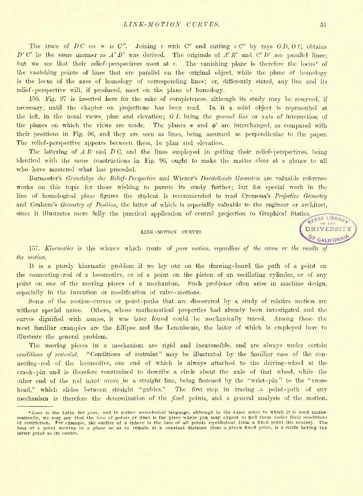
LINK-MOTION CURVES. 51
The trace of D C on v is C ". Joining v with C" and cutting v C" by rays D, C, obtains
D' C' in the same manner as A' B' was derived. The originals of A' B' and C' D' are parallel lines;
but we see that their relief-perspectives meet at v. The vanishing plane is therefore the locus* of
the vanishing points of lines that are parallel on the original object, while the plane of homologyis the locus of the axes of homology of corresponding lines; or, differently stated, any line and its
relief -perspective will, if produced, meet on the plane of homology.
156. Fig. 97 is inserted here for the sake of completeness, although its study may be reserved, if
necessary, until the chapter on projections has been read. In it a solid object is represented at
the left, in the usual views, plan and elevation; G L being the ground line or axis of intersection of
the planes on which the views are made. The planes ?r and <f> are interchanged, as compared with
their positions in Fig. 96, and they are seen as lines, being assumed as perpendicular to the paper.
The relief- perspective appears between them, in plan and elevation.
The lettering of A B and D C, and the lines employed in getting their relief- perspectives, being
identical with the same constructions in Fig. 96, ought to make the matter clear at a glance to all
who have mastered what has preceded.
Burmester's Grundzuge der Relief- Perspective and Wiener's Darstellende Geometric are valuable reference
works on this topic for those wishing to pursue its study further; but for special work in the
line of homological plane figures the student is recommended to read Cremona's Projective Geometry
and Graham's Geometry of Position, the latter of which is especially valuable to the engineer or architect,
since it illustrates more fully the practical application of central projection to Graphical Statics.^-^==^~
LINK-MOTION CURVES
157. Kinematics is the science which treats of pure motion, regardless of the cause or the results of
the motion.
It is a purely kinematic problem if we lay out on the drawing-board the path of a point on
the connecting-rod of a locomotive, or of a point on the piston of an oscillating cylinder, or of any
point on one of the moving pieces of a mechanism. Such problems often arise in machine design,
especially in the invention or modification of valve - motions.
Some of the motion -curves or point -paths that are discovered by a study of relative motion are
without special name. Others, whose mathematical properties had already been investigated and the
curves dignified with names, it was later found could be mechanically traced. Among these the
most familiar examples are the Ellipse and the Lemniscate, the latter of which is employed here to
illustrate the general problem.
The moving pieces in a mechanism are rigid and inextensible, and are always under certain
conditions of restraint. "Conditions of restraint" may be illustrated by the familiar case of the con-
necting-rod of the locomotive, one end of Avhich is always attached to the driving-wheel at the
crank -pin and is therefore constrained to describe a circle about the axle of that wheel, while the
other end of the rod must move,in a straight line, being fastened by the "wrist-pin" to the "cross-
head," which slides between straight "guides." The first step in tracing .a point -path of any
mechanism is therefore the determination of the fixed points, and a general analysis of the motion.
"Locus is the Latin for place; and in rather untechnical language, although in the exact sense in which it is used mathe-
matically, we may say that the loms of points or lines is the place where you may expect to find them under their conditions
of restriction. For example, the surface of a sphere is the locus of all points equidistant from a fixed point (Its centre). Thelocus of a point moving in a plane so as to remain at a constant distance from a given fixed point, is a circle having thelatter point as its centre.
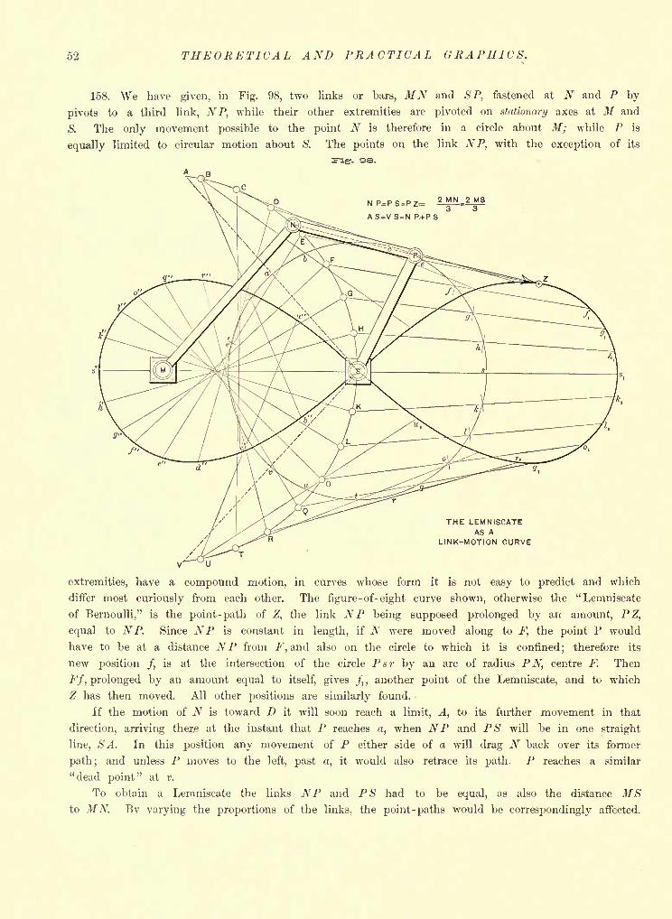
52 THEORETICAL AND PRACTICAL GRAPHICS.
158. We have given, in Fig. 98, two links or bars, MN and S P, fastened at N and P by
pivots to a third link, NP, while their other extremities are pivoted on stationary axes at M and
S. The only movement possible to the point N is therefore in a circle about M; while P is
equally limited to circular motion about S. The points on the link NP, with the exception of its
2 MN 2 MS
THE LEMNISCATEAS A
LINK-MOTION CURVE
extremities, have a compound motion, in curves whose form it is not easy to predict and which
differ most curiously from each other. The figure-of-eight curve shown, otherwise the "Lemniscate
of Bernoulli," is the point -path of Z, the link NP being supposed prolonged by an amount, P Z,
equal to NP. Since NP is constant in length, if N were moved along to F, the point P would
have to be at a distance NP from F, and also on the circle to which it is confined; therefore its
new position /, is at the intersection of the circle Psr by an arc of radius PN, centre F. Then
Ff, prolonged by an amount equal to itself, gives /, ,another point of the Lemniscate, and to which
Z has then moved. All other positions are similarly found.
If the motion of N is toward D it will soon reach a limit, A, to its further movement in that
direction, arriving ther.e at the instant that P reaches a, when NP and PS will be in one straight
line, SA. In this position any movement of P either side of a will drag N back over its former
path; and unless P moves to the left, past a, it would also retrace its path. P reaches a similar
"dead point" at v.
To obtain a Lemniscate the links NP and PS had to be equal, as also the distance MSto MN. Bv varying the proportions of the links, the point- paths would be correspondingly affected.
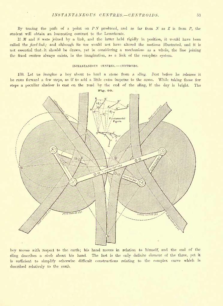
INSTANTANEOUS CENTRES. CENTRO 1 DS. 53
By tracing the path of a point on PN produced, and as far from N as Z is from P, the
student will obtain an interesting contrast to the Lemniscate.
If M and S were joined by a link, and the latter held rigidly in position, it would have been
called the fixed link; and although its use would not have altered the motions illustrated, and it is
not essential that . it should be drawn, yet in considering a mechanism as a whole, the line joining
the fixed centres always exists, in the imagination, as a link of the complete system.
INSTANTANEOUS CENTRES. CENTROIDS.
159. Let us imagine a boy about to hurl a stone from a sling. Just before he releases it
he runs forward a few steps, as if to add a little extra impetus to the stone. While taking those few
steps a peculiar shadow is cast on the road by the end of the sling, if the day is bright. The
boy moves with respect to the earth; his hand moves in relation to himself, and the end of the
sling describes a circle about his hand. The last is the only definite element of the three, yet it
is sufficient to simplify otherwise difficult constructions relating to the complex curve which is
described relatively to the earth.
54 THEORETICAL AND PRACTICAL GRAPHICS.
A tangent and a normal to a circle are easily obtained, the former being, as need hardly be
stated at this point, perpendicular to the radius at the point of tangency, while the normal simply
coincides in direction with such radius. If the stone were released at any instant it would fly off
in a straight line, tangent to the circle it was describing about the hand as a centre; but such line
would, at the instant of release, be tangent also to the compound curve. If, then, we wish a tangent
at a given point of any curve generated by a point in motion, we have but to reduce that motion
to circular motion about some moving centre; then, joining the point of desired tangency with the
at that instant position of the moving centre, we have the normal, a perpendicular to which gives
the tangent desired.
A centre which is thus used for an instant only is called an instantaneous centre.
160. In Fig. 99 a series of instantaneous centres are shown and an important as well as inter-
esting fact illustrated, viz., that every moving piece in a mechanism might be rigidly attached to a
certain curve, and by the rolling of the latter upon another curve the link might be brought into
all the positions which its visible modes of restraint compel it to take.
161. In the "Fundamental" part of Fig. 99 A B is assumed to be one position of a link. Wenext find it, let us suppose, at A' B', A having moved over A A', and B over BB'. Bisecting
A A' and B B' by perpendiculars intersecting at 0, and drawing A, OA', OB and OB', we
have A A' = 6t= B OB', and evidently a point about which, as a centre, the turning of AB
through the angle 0, would have brought it to A' B'. Similarly, if the next position in which we
find AB is A" B", we may find a point s as the centre about which it might have turned to
bring it there; the angle being 2 , probably different from 0,. N and m are analogous to and s.
If Os' be drawn equal to Os and making with the latter an angle 0,, equal to the angle
A OA', and if Os were rigidly attached to A B, the latter would be brought over to A' B' by
bringing s' into coincidence with s. In the same manner, if we bring s' n' upon s n throughan angle 2
about s, then the next position, A" B", would be reached by A B. 0' s' n' m' is then
part of a polygon whose rolling upon Osnm would bring A B into all the positions shown, provided
the polygon and the line were so attached as to move as one piece. Polygons whose vertices are
thus obtained are called central polygons.
If consecutive centres were joined we would have curves, called centroids*, instead of polygons;
the one corresponding to Osnm being called the fixed, the other the rolling centroid. The perpen-
dicular from upon A A '
is a normal to that path. But were A to move in a circle, the normal
to its path at any instant would be simply the radius to the position of A at that instant.
If, then, both A and B were moving in circular paths, we would find the instantaneous centre
at the intersection of the normals (radii) at the points A and B.
162. In Fig. 98 the instantaneous centre about which the whole link NP is turning, is at the
intersection of radii MN and SP (produced); and calling it X we would have XZ for the normal
at Z to the Lemniscate.
163. The shaded portions of Fig. 99 illustrate some of the forms of centroids.
The mechanism is of four links, opposite links equal. Unlike the usual quadrilateral fulfilling
this condition, the long sides cross, hence the name "anti- parallelogram."
The "fixed link (a)" corresponds to MS of Fig. 98, and its extremities are the centres of
rotation of the short links, whose ends, / and /,, describe the dotted circles.
For the given position T is evidently the instantaneous centre. Were a bar pivoted at T and
*Reuleaux' nomenclature; also called centrodes by a number of writers on Kinematics.
TROCHOIDS. 55
fastened at right angles to "moving link (a)," an infinitesimal turning about T would move "link
(a)" exactly as under the old conditions.
By taking "link (a)" in all possible positions, and, for each, prolonging the radii through its
extremities, the points of the fixed centroid are determined. Inverting the combination so that
"moving link (a)" and its opposite are interchanged, and proceeding as before, gives the points of
"rolling centroid (a)."
These centroids are branches of hyperbolas having the extremities of the long links as foci.
By holding a short link stationary, as "fixed link (b)," an elliptical fixed centroid results;
"rolling centroid (b)" being obtained, as before, by inversion. The foci are again the extremities of
the fixed and moving links.
Obviously, the curved pieces represented as screwed to the links would not be employed in a
practical construction, and they are only introduced to give a more realistic effect to the figure and
possibly thereby conduce to a clearer understanding of the subject.
164. It is interesting to notice that the Lemniscate occurs here under new conditions, being
traced by the middle point of "moving link (a)."
The study of kinematics is both fascinating and profitable, and it is hoped that this brief glance
at the subject may create a desire on the part of the student to pursue it further in such works as
Reauleaux' Kinematics of Machinery and Burmester's Lehrbuch der Kinematik.
165. Before leaving this topic the important fact should be stated, which now needs no argument
to establish, that the instantaneous centre, for any position of a moving piece, is the point of
contact of the rolling and fixed centroids. We shall have occasion to use this principle in drawing
tangents and normals to the
TROCHOIDS
which are the principal Roulettes, or roll -traced curves, and which may be defined as follows:
If, in the same plane, one of two circles roll upon the other without sliding, the path of any
point on a radius of the rolling circle or on the radius produced is a trochoid.
166. The Cycloid. Since a straight line may be considered a circle of infinite radius, the above
definition would include the curve traced by a point on the circumference of a locomotive wheel as
it rolls along the rail, or of a carriage wheel on the road. This curve is known as a cycloid* and
is shown in T n a bc, Fig. 100. It is the proper outline for a portion of each tooth in a certain
case of gearing, viz., where one wheel has an infinite radius, that is, becomes a "rack."
Were T6a ceiling -corner of a room, and Ta the diagonally opposite floor-corner, a weight would
slide from T& to Tu more quickly on guides curved in cycloidal shape than if shaped to any other
curve, or if straight. If started at s, or any other point of the curve, it would reach Ta as soon
as if started at Te
.
167. In beginning the construction of the cycloid we notice, first, that as T VD rolls on the
straight line A B, the arrow DRT will be reversed in position (as at -D5T
6) as soon as the semi-
circumference T3Z) has had rolling contact with A B. The tracing point will then be at T6 ,its
maximum distance from A B.
When the wheel has rolled itself out once upon the rail, the point T will again come in contact
with the rail, as at jT12
.
*" Although the invention of the cycloid is attributed to Galileo, it is certain that the family of curves to which it belongshad been known and some of the properties of such curves investigated, nearly two thousand years before Galileo's time, if
not earlier. For ancient astronomers explained the motion of the planets by supposing that each planet travels uniformlyround a circle whose centre travels uniformly around another circle." Proctor, Geometry of Cycloids.
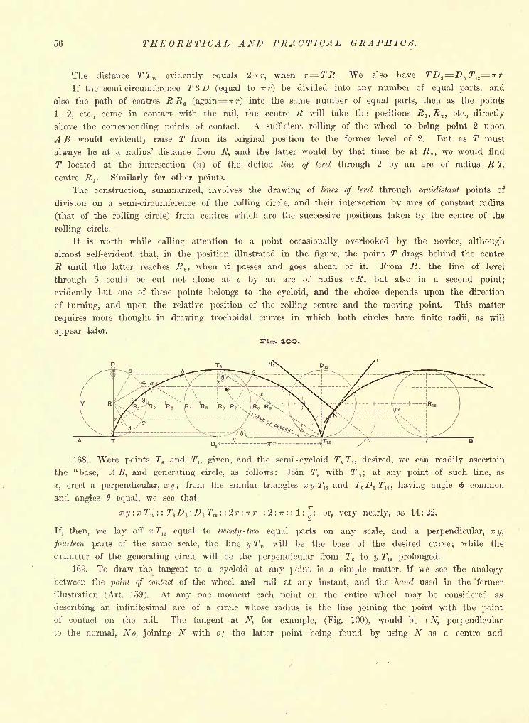
56 THEORETICAL AND PRACTICAL GRAPHICS.
The distance TT12 evidently equals 2*r, when r=TR. We also have
If the semi-circumference T3D (equal to irr) be divided into any number of equal parts, and
also the path of centres RR e (again= irr) into the same number of equal parts, then as the points
1, 2, etc., come in contact with the rail, the centre R will take the positions J2j,JS 2 , etc., directly
above the corresponding points of contact. A sufficient rolling of the wheel to br-ing point 2 upon
A B would evidently raise T from its original position to the former level of 2. But as T must
always be at a radius' distance from R, and the latter would by that time be at R lt we would find
T located at the intersection () of the dotted line of level through 2 by an arc of radius R T,
centre R2
. Similarly for other points.
The construction, summarized, involves the drawing of lines of level through equidistant points of
division on a semi-circumference of the rolling circle, and their intersection by arcs of constant radius
(that of the rolling circle) from centres which are the successive positions taken by the centre of the
rolling circle.
It is worth while calling attention to a point occasionally overlooked by the novice, although
almost self-evident, that, in the position illustrated in the figure, the point T drags behind the centre
R until the latter reaches Re ,
when it passes and goes ahead of it. From R1
the line of level
through 5 could be cut not alone at c by an arc of radius cR, but also in a second point;
evidently but one of these points belongs to the cycloid, and the choice depends upon the direction
of turning, and upon the relative position of the rolling centre and the moving point. This matter
requires more thought in drawing trochoidal curves in which both circles have finite radii, as will
appear later.
-. OO.
168. Were points T6and T
12 given, and the semi -cycloid T6T
12 desired, we can readily ascertain
the "base," A B, and generating circle, as follows: Join T6 with T12 ;
at any point of such line, as
x, erect a perpendicular, xy; from the similar triangles xyTtl and T^D^T^, having angle <f> common
and angles equal, we see that
xy:xTM :: T6 .D 5: Z>
5T
12: : 2r : TTT- : : 2 : *: : 1 :
; or, very nearly, as 14:22.a
If, then, we lay off x T]2 equal to twenty -two equal parts on any scale, and a perpendicular, xy,
fourteen parts of the same scale, the line y Tn will be the base of the desired curve; while the
diameter of the generating circle will be the perpendicular from Te to y Tu prolonged.
169. To draw the tangent to a cycloid at any point is a simple matter, if we see the analogy
between the point of contact of the wheel and rail at any instant, and the hand used in the former
illustration (Art. 159). At any one moment each point on the entire wheel may be considered as
describing an infinitesimal arc of a circle whose radius is the line joining the point with the point
of contact on the rail. The tangent at N, for example, (Fig. 100), would be t N, perpendicular
to the normal, No, joining N with o; the latter point being found by using N as a centre and
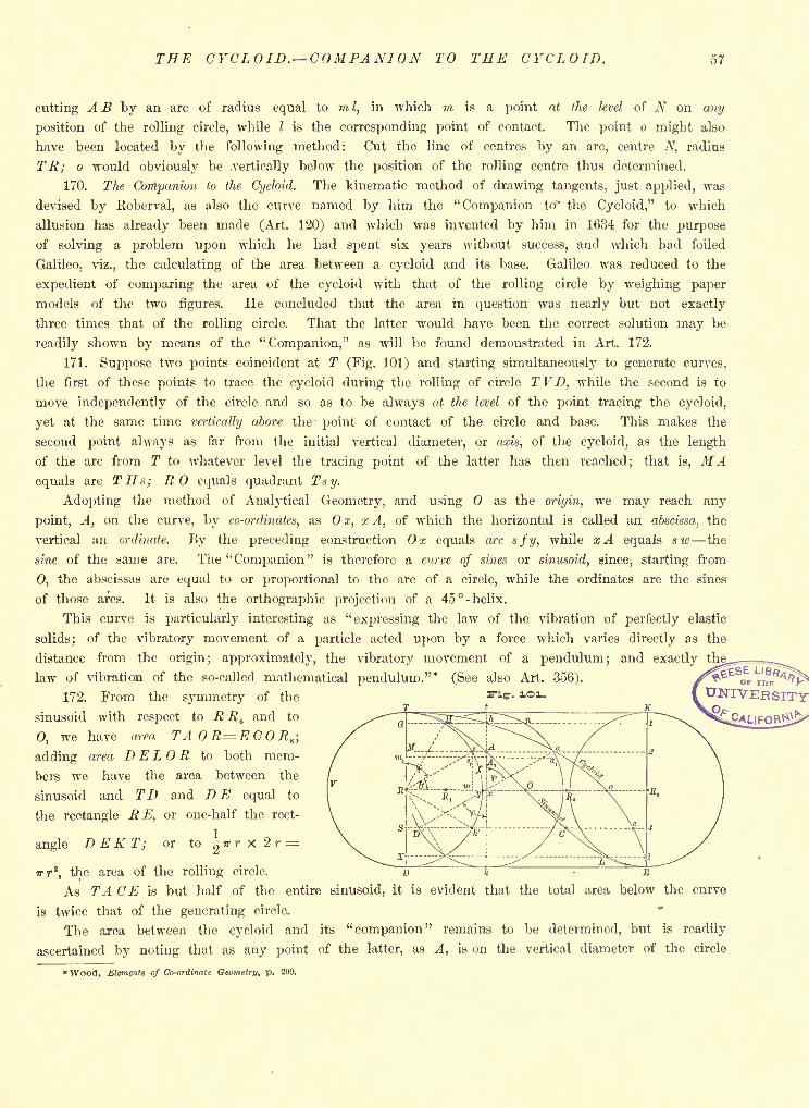
THE CYCLOID. COMPANION TO THE CYCLOID. 57
cutting AS by an arc of radius equal to mI,
in which m is a point at the level of N on any
position of the rolling circle, while I is the corresponding point of contact. The point o might also
have been located by the following method: Cut the line of centres by an arc, centre N, radius
TR; o would obviously be .vertically below the position of the rolling centre thus determined.
170. The Companion to the Cycloid. The kinematic method of drawing tangents, just applied, was
devised by Roberval, as also the curve named by him the "Companion to' the Cycloid," to which
allusion has already been made (Art. 120) and which was invented by him in 1634 for the purpose
of solving a problem upon which he had spent six years without success, and which had foiled
Galileo, viz., the calculating of the area between a cycloid and its base. Galileo was reduced to the
expedient of comparing the area of the cycloid with that of the rolling circle by weighing paper
models of the two figures. He concluded that the area in question was nearly but not exactly
three times that of the rolling circle. That the latter would have been the correct solution may be
readily shown by means of the "Companion," as will be found demonstrated in Art. 172.
171. Suppose two points coincident at T (Fig. 101) and starting simultaneously to generate curves,
the first of these points to trace the cycloid during the rolling of circle TVD, while the second is to
move independently of the circle and so as to be always at the level of the point tracing the cycloid,
yet at the same time vertically above the point of contact of the circle and base. This makes the
second point always as far from the initial vertical diameter, or axis, of the cycloid, as the length
of the arc from T to whatever level the tracing point of the latter has then reached; that is, MAequals arc THs; RO equals quadrant Tsy.
Adopting the method of Analytical Geometry, and using as the origin, we may reach any
point, A, on the curve, by co-ordinates, as Ox, x A, of which the horizontal is called an abscissa, the
vertical an ordinate. By the preceding construction Ox equals arc sfy, while xA equals siv the
sine of the same arc. The "Companion" is therefore a curve of sines or sinusoid, since, starting from
0, the abscissas are equal to or proportional to the arc of a circle, while the ordinates are the sines
of those arcs. It is also the orthographic projection of a 45 -helix.
This curve is particularly interesting as "expressing the law of the vibration of perfectly elastic
solids; of the vibratory movement of a particle acted upon by a force which varies directly as the
distance from the origin; approximately, the vibratory movement of a pendulum; and exactly the,
law of vibration of the so-called mathematical pendulum."* (See also Art. 356).
172. From the symmetry of the
sinusoid with respect to RR6and to
0, we have area TAOR=ECORe ;
adding area D EL R to both mem-
bers we have the area between the
sinusoid and TD and DE equal to
the rectangle R E, or one-half the rect-
angle D E K T; or to^* r X 2 r =
Trr2
,the area of the rolling circle.
As TA CE is but half of the entire sinusoid, it is evident that the total area below the curve
is twice that of the generating circle.
The area between the cycloid and its "companion" remains to be determined, but is readily
ascertained by noting that as any point of the latter, as A, is on the vertical diameter of the circle
* Wood, Elements of Co-ordinate Geometry, p. 209.
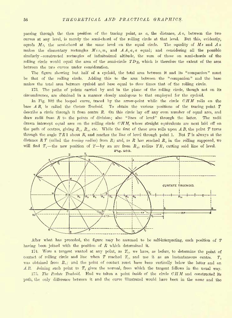
58 THEORETICAL AND PRACTICAL GRAPHICS.
passing through the then position of the tracing point, as a, the distance, A a, between the two
curves at any level, is merely the semi-chord of the rolling circle at that level. But this, evidently,
equals Ms, the semi-chord at the same level on the equal circle. The equality of Ms and A a
makes the elementary rectangles Mss1m
land AA
la
la equal; and considering all the possible
similarly - constructed rectangles of infinitesimal altitude, the sum of those on semi-chords of the
rolling circle would equal the area of the semi-circle TDy, which is therefore the extent of the area
between the two curves under consideration.
The figure showing but half of a cycloid, the total area between it and its "companion" must
be that of the rolling circle. Adding this to the area between the "companion" and the base
makes the total area between cycloid and base equal to three times that of the rolling circle.
173. The paths of points carried by and in the plane of the rolling circle, though not on its
circumference, are obtained in a manner closely analogous to that employed for the cycloid.
In Fig. 102 the looped curve, traced by the arrow-point while the circle CHM rolls on the
base A B, is called the Curtate Trochoid. To obtain the various positions of the tracing point Tdescribe a circle through it from centre R. On this circle lay off any even number of equal arcs, and
draw radii from R to the points of division; also "lines of level" through the latter. The radii
drawn intercept equal arcs on the rolling circle CHM, whose straight equivalents are next laid off on
the path of centres, giving R lt R 2 ,etc. While the first of these arcs rolls upon A B, the point T turns
through the angle TR 1 about R, and reaches the line of level through point 1. But T is always at the
distance R T (called the tracing radius) from R; and, as R has reached R}in the rolling supposed, we
will find T1
the new position of T by an arc from R lt radius TR, cutting said line of level.
-. 1O3.
___4 1 -(-4 , -,
After what has preceded, the figure may be assumed to be self-interpreting, each position of T
having been joined with the position of R which determined it.
174. Were a tangent wanted at any point, as T,, we have, as before, to determine the point of
contact of rolling circle and line when T reached T,, and use it as an instantaneous centre. 7",
was obtained from .R,; and the point of contact must have been vertically below the latter and on
A B. Joining such point to T, gives the normal, from which the tangent follows in the usual way.
175. The Prolate Trochoid. Had we taken a point inside of the circle CHM and constructed its
path, the only difference between it and the curve illustrated would have been in the name and the
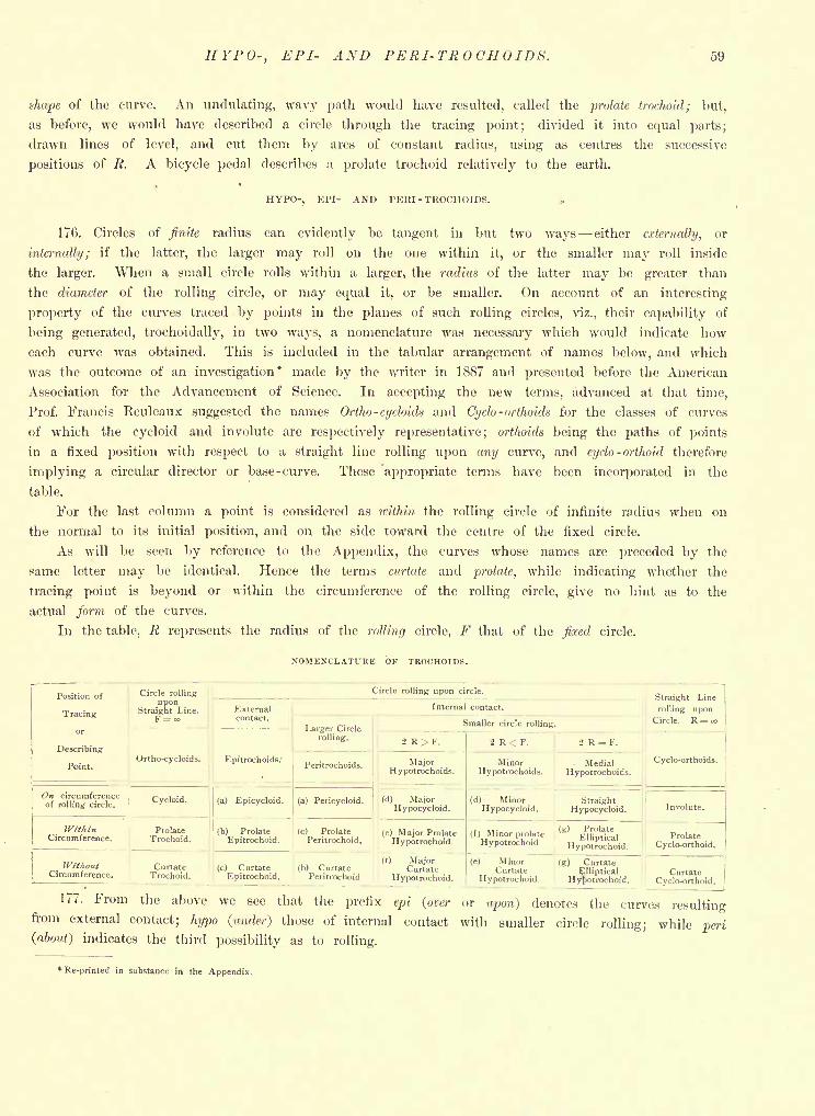
HYPO-, EPI- AND PERI-TROCHOIDS. 59
shape of the curve. An undulating, wavy path would have resulted, called the prolate trochoid; but,
as before, we would have described a circle through the tracing point; divided it into equal parts;
drawn lines of level, and cut them by arcs of constant radius, using as centres the successive
positions of R. A bicycle pedal describes a prolate trochoid relatively to the earth.
HYPO-, KI'I- AND PERI-TROCHOIDS. ,
176. Circles of finite radius can evidently be tangent in but two ways either externally, or
Internally; if the latter, the larger may roll on the one within it, or the smaller may roll inside
the larger. When a small circle rolls within a larger, the radius of the latter may be greater than
the diameter of the rolling circle, or may equal it, or be smaller. On account of an interesting
property of the curves traced by points in the planes of such rolling circles, viz., their capability of
being generated, trochoidally, in two ways, a nomenclature was necessary which would indicate how
each curve was obtained. This is included in the tabular arrangement of names below, and which
was the outcome of an investigation* made by the writer in 1887 and presented before the American
Association for the Advancement of Science. In accepting the new terms, advanced at that time,
Prof. Francis Reuleaux suggested the names Ortho- cycloids and Cydo-orthoids for the classes of curves
of which the cycloid and involute are respectively representative; orthoids being the paths of points
in a fixed position with respect to a straight line rolling upon any curve, and cydo-orthoid therefore
implying a circular director or base- curve. These 'appropriate terms have been incorporated in the
table.
For the last column a point is considered as within the rolling circle of infinite radius when on
the normal to its initial position, and on the side toward the centre of the fixed circle.
As will be seen by reference to the Appendix, the curves whose names are preceded by the
same letter may be identical. Hence the terms curtate and prolate, while indicating whether the
tracing point is beyond or within the circumference of the rolling circle, give no hint as to the
actual form of the curves.
In the table, R represents the radius of the rolling circle, F that of the fixed circle.
NOMENCLATURE OF TROCHOIDS.
Position of
Tracing
or
Describing
Point.
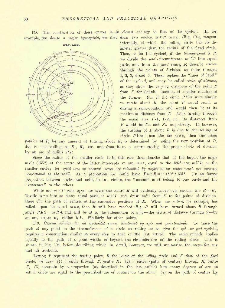
60 THEORETICAL AND PRACTICAL GRAPHICS.
r- 1O3.
178. The construction of these curves is in closest analogy to that of the cycloid. If, for
example, we desire a major hypocycloid, we first draw two circles, mVP, mxL, (Fig. 103), tangent
internally, of which the rolling circle has its di-
ameter greater than the radius of the fixed circle.
Then, as for the cycloid, if the tracing -point is P,
we divide the semi -circumference m VP into equal
parts, and from the fixed centre, F, describe circles
through the points of division, as those through
1, 2, 3, 4 and 5. These replace the "lines of level"
of the cycloid, and may be called circles of distance,
as they show the varying distances of the point Pfrom F, for definite amounts of angular rotation of
the former. For if the circle PVm were simply
to rotate about R, the point P would reach m
during a semi -rotation, and would then be at its
maximum distance from F. After turning through
the equal arcs P-l, 1-2, etc., its distances from
F would be Fa and Fb respectively. If, however,
the turning of P about R is due to the rolling of
circle PVm upon the arc mxz, then the actual
position of P, for any amount of turning about R, is determined by noting the new position of R,
due to such rolling, as B 1} R^, etc., and from it as a centre cutting the proper circle of distance
by an arc of radius R P.
Since the radius of the smaller circle is in this case three -fourths that of the larger, the angle
mFz (135), at the centre of the latter, intercepts an arc, mxz, equal to the 180 -arc, m V P, on the
smaller circle; for equal arcs on unequal circles are subtended by angles at the centre which are inversely
proportional to the radii. As a proportion we would have Fm:Rm:: 180 : 135. (In an inverse
proportion between angles and radii, in two circles, the "means" must belong to one circle and the" extremes "
to the other).
While arc m V P rolls upon arc mxz, the centre R will evidently move over circular arc R R6
.
Divide mxz into as many equal parts as mV P and draw radii from F to the points of division;
these cut the path of centres at .the successive positions of R. When arc m 5-4, for example, has
rolled upon its equal muv, then R will have reached R2 ;
P will have turned about R through
angle PR2 = mR4, and will be at n, the intersection of b/g the circle of distance through 2 byan arc, centre R 2 ,
radius R P. Similarly for other points.
179. General solution for all trochoidal curves, illustrated by epi- and peri-trochoids. To trace the
path of any point on the circumference of a circle so rolling as to give the epi- or peri -cycloid,
requires a construction similar at every step to that of the last article. The same remark applies
equally to the path of a point within or beyond the circumference of the rolling circle. This is
shown in Fig. 104, before describing which in detail, however, we will summarize the steps for any
and all trochoids.
Letting P represent the tracing point, R the centre of the rolling circle and F that of the fixed
circle, we draw (1) a circle through P, centre R; (2) a circle (path of centres) through R, centre
F; (3) ascertain by a proportion (as described in the last article) how many degrees of arc on
either circle are equal to the prescribed arc of contact on the other; (4) on the path of centres lay
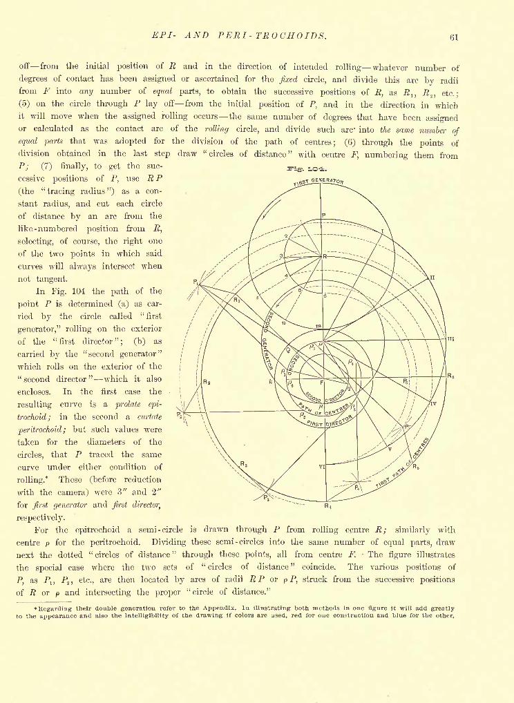
EPI- AND PERI-TROCHOIDS. 61
O-i.
off from the initial position of R and in the direction of intended rolling whatever number of
degrees of contact has been assigned or ascertained for the fixed circle, and divide this arc by radii
from F into any number of equal parts, to obtain the successive positions of R, as R l} R.2 , etc.;
(5) on the circle through P lay off from the initial position of P, and in the direction in whichit will move when the assigned rolling occurs the same number of degrees that have been assignedor calculated as the contact arc of the rolling circle, and divide such arc' into the same number of
equal parts that was adopted for the division of the path of centres; (6) through the points of
division obtained in the last step draw "circles of distance" with centre F, numbering them from
P; (7) finally, to get the suc-
cessive positions of P, use R P
(the"tracing radius ") as a con-
stant radius, and cut each circle
of distance by an arc from the
like - numbered position from R,
selecting, of course, the right one
of the two points in which said
curves will always intersect when
not tangent.
In Fig. 104 the path of the
point P is determined (a) as car-
ried by the circle called"first
generator," rolling on the exterior
of the "first director"; (b) as
carried by the "second generator"
which rolls on the exterior of the
"second director" which it also
encloses. In the first case the
resulting curve is a prolate epi-
trochoid; in the second a curtate
peritrochoid; but such values were
taken for the diameters of the
circles, that P traced the same
curve under either condition of
rolling.* These (before reduction
with the camera) were 3" and 2"
for first generator and first director,
respectively.
For the epitrochoid a semi -circle is drawn through P from rolling centre R; similarly with
centre p for the peritrochoid. Dividing these semi -circles into the same number of equal parts, draw
next the dotted"circles of distance
"through these points, all from centre F. The figure illustrates
the special case where the two sets of"circles of distance
"coincide. The various positions of
P, as Pn P2 , etc., are then located by arcs of radii RP or p P, struck from the successive positions
of R or p and intersecting the proper "circle of distance."
Regarding their double generation refer to the Appendix. In illustrating both methods In one figure it will add greatlyto the appearance and also the intelligibility of the drawing if colors are used, red for one construction and blue for the other.
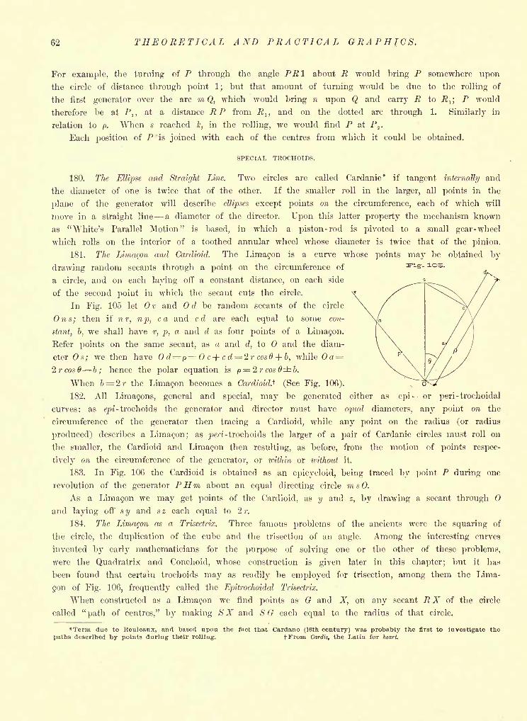
62 THEORETICAL AND PRACTICAL GRAPHICS.
For example, the turning of P through the angle PR I about R would bring P somewhere upon
the circle of distance through point 1; but that amount of turning would be due to the rolling of
the first generator over the arc m Q, which would bring n upon Q and carry R to 7?,; P would
therefore be at /',, at a distance RP from R lt and on the dotted arc through 1. Similarly in
relation to p. When s reached k, in the rolling, we would find P at P2
.
Each position of P is joined with each of the centres from which it could be obtained.
SPECIAL TROCHOIDS.
180. The Ellipse and Straight Line. Two circles are called Cardanic* if tangent internally and
the diameter of one is twice that of the other. If the smaller roll in the larger, all points in the
plane of the generator will describe ellipses except points on the circumference, each of which will
move in a straight line a diameter of the director. Upon this latter property the mechanism known
as "White's Parallel Motion" is based, in which a piston-rod is pivoted to a small gear-wheel
which rolls on the interior of a toothed annular wheel whose diameter is twice that of the pinion.
181. The Limacon and Cardioid. The Limacon is a curve whose points may be obtained by
drawing random secants through a point on the circumference of
a circle, and on each laying off a constant distance, on each side
of the second point in which the secant cuts the circle.
In Fig. 105 let v and d be random secants of the circle
Ons; then if nv, np, ca and cd are each equal to some con-
stant, b, we shall have v, p, a and d as four points of a Lima9on.
Refer points on the same secant, as a and d, to and the diam-
eter Os; we then have Od p= Oc+cd=2r cos6 + b, while Oa =
2 r cos 6 b ; hence the polar equation is p = 2rcos#i.
When b= L2r the Limacon becomes a Cardioid.^ (See Fig. 106).
182. All Limafons, general and special, may be generated either as epi- or peri-trochoidal
curves: as gpi-trochoids the generator and director must have equal diameters, any point on the
circumference of the generator then tracing a Cardioid, while any point on the radius (or radius
produced) describes a Limacon; as j>m-trochoids the larger of a pair of Cardanic circles must roll on
the smaller, the Cardioid and Limacon then resulting, as before, from the motion of points respec-
tively on the circumference of the generator, or within or without it.
183. In Fig. 106 the Cardioid is obtained as an epicycloid, being traced by point P during one
revolution of the generator PHm about an equal directing circle msO.
As a Limacon we may get points of the Cardioid, as y and z, by drawing a secant through
and laying off s y and s z each equal to 2 r.
184. The Limayon as a Trisectrix. Three famous problems of the ancients were the squaring of
the circle, the duplication of the cube and the trisection of an angle. Among the interesting curves
invented by early mathematicians for the purpose of solving one or the other of these problems,
were the Quadratrix and Conchoid, whose construction is given later in this chapter; but it has
been found that certain trochoids may as readily be employed for trisection, among them the Lima-
gon of Fig. 106, frequently called the Epitrochoidal Trisectrix.
When constructed as a Limacon we find points as G and X, on any secant R X of the circle
called"path of centres," by making SX and S G each equal to the radius of that circle.
*Tenn due to Keuleaux, and based upon the fact that Cardano (16th century) was probably the first to investigate the
paths described by points during their rolling. fFrom Cardis, the Latin for heart.
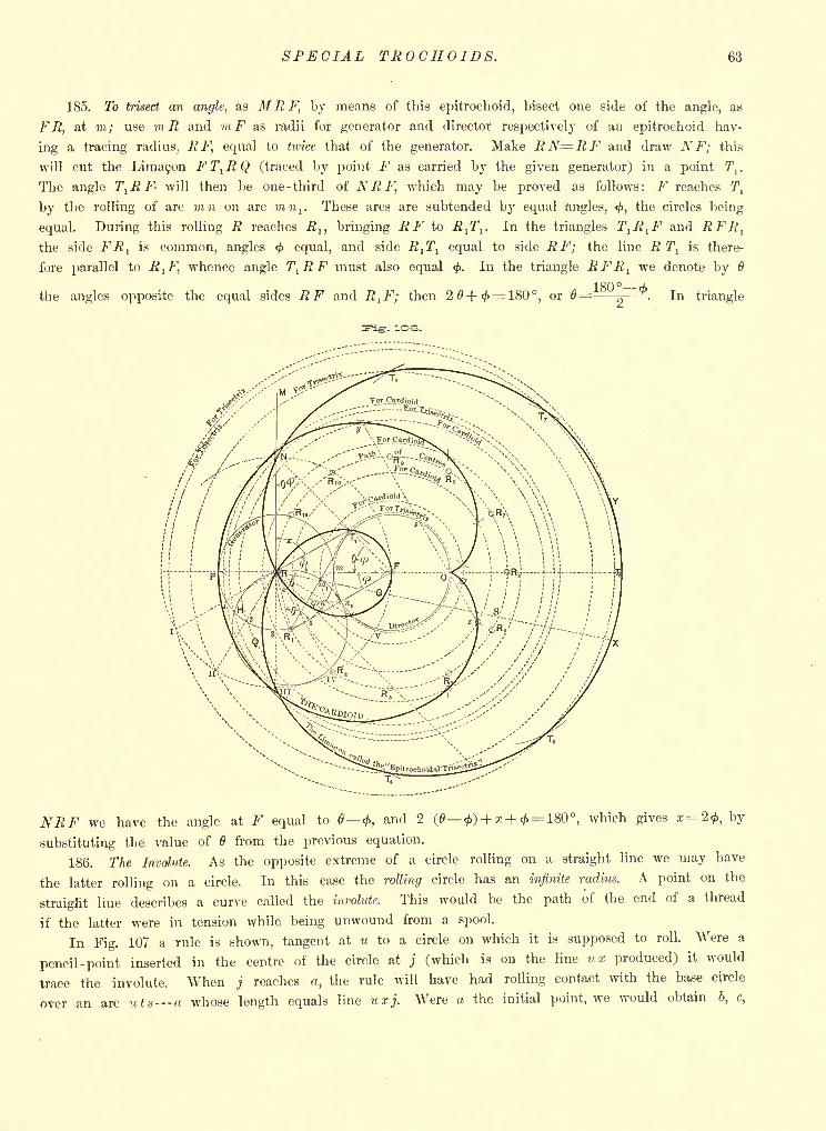
SPECIAL TROCHOIDS. 63
185. To trisect an angle, as MR F, l>y means of this epitrochoid, bisect one side of the angle, as
F R, at m; use ?7i R and mF as radii for generator and director respectively of an epitrochoid hav-
ing a tracing radius, RF, equal to twice that of the generator. Make RN=RF and draw NF; this
will cut the Lima9on FT}RQ (traced by point F as carried by the given generator) in a point 1\ .
The angle T^F- will then be one -third of NRF, which may be proved as follows: F reaches T,
by the rolling of arc mn on arc win,. These arcs are subtended by equal angles, <#>,the circles being
equal. During this rolling R reaches .R,, bringing R F to R1 7\ . In the triangles T^R^F and RFR
t
the side FRl
is common, angles <j> equal, and side -fi^T7
, equal to side RF; the line R Tl
is there-
fore parallel to Rt F, whence angle T^RF must also equal <f>.
In the triangle RFR lwe denote by
the angles opposite the equal sides RF and R1 F; then or
1 QQO_ i
0=- . In triangle
. 10S.
we have the angle at F equal to <, and 2 (6 <) + * + <^= 180, which gives a;=2<, by
substituting the value of 6 from the previous equation.
186. The Involute. As the opposite extreme of a circle rolling on a straight line we may have
the latter rolling on a circle. In this case the rolling circle has an infinite radius. A point on the
straight line describes a curve called the involute. This would be the path of the end of a thread
if the latter were in tension while being unwound from a spool.
In Fig. 107 a rule is shown, tangent at M to a circle on which it is supposed to roll. Were a
pencil -point inserted in the centre of the circle at j (which is on the line ux produced) it would
trace the involute. When j reaches a, the rule will have had rolling contact with the base circle
over an arc uts u whose length equals line uxj. Were a the initial point, we would obtain 6, c,
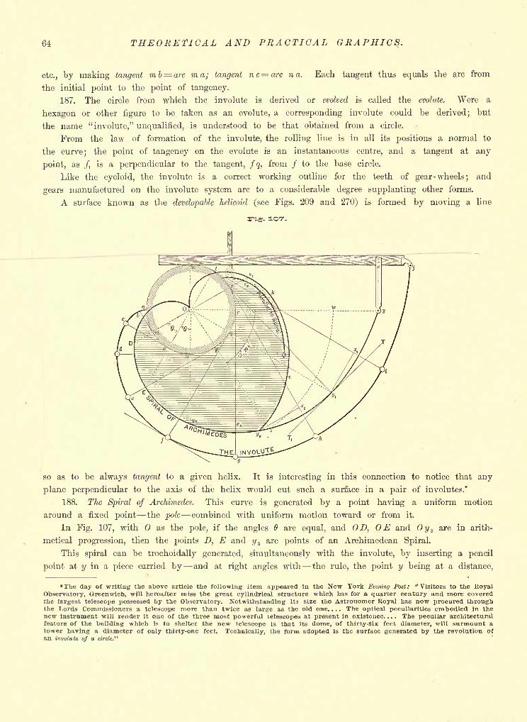
64 THEORETICAL AND PRACTICAL GRAPHICS.
etc., by making tangent mb= arc ma; tangent nc=arc na. Each tangent thus equals the arc from
the initial point to the point of tangency.
187. The circle from which the involute is derived or evolved is called the evolute. Were a
hexagon or other figure to be taken as an evolute, a corresponding involute could be derived; but
the name "involute," unqualified, is understood to be that obtained from a circle.
From the law of formation of the involute, the rolling line is in all its positions a normal to
the curve; the point of tangency on the evolute is an instantaneous centre, and a tangent at any
point, as /, is a perpendicular to the tangent, fq, from / to the base circle.
Like the cycloid, the involute is a correct working outline for the teeth of gear-wheels; and
gears manufactured on the involute system are to a considerable degree supplanting other forms.
A surface known as the developable helicoid (see Figs. 209 and 270) is formed by moving a line
-- 1O7.
so as to be always tangent to a given helix. It is interesting in this connection to notice that any
plane perpendicular to the axis of the helix would cut such a surface in a pair of involutes.*
188. The Spiral of Archimedes. This curve is generated by a point having a uniform motion
around a fixed point the pole combined with uniform motion toward or from it.
In Fig. 107, with as the pole, if the angles are equal, and D, OE and Oy 3are in arith-
metical progression, then the points D, E and i/ 3are points of an Archimedean Spiral.
This spiral can be trochoidally generated, simultaneously with the involute, by inserting a pencil
point at y in a piece carried by and at right angles with the rule, the point y being at a distance,
The day of writing the above article the following item appeared in the New York Evening Post: "Visitors to the RoyalObservatory, Greenwich, will hereafter miss the great cylindrical structure which has for a quarter century and more coveredthe largest telescope possessed by the Observatory. Notwithstanding its size the Astronomer Koyal has now procured throughthe Lords Commissioners a telescope more than twice as large as the old one. . . . The optical peculiarities embodied in thenew instrument will render it one of the three most powerful telescopes at present in existence.... The peculiar architecturalfeature of the building which is to shelter the new telescope is that its dome, of thirty-six feet diameter, will surmount atower having a diameter of only thirty-one feet. Technically, the form adopted is the surface generated by the revolution ofan involute of a circte."
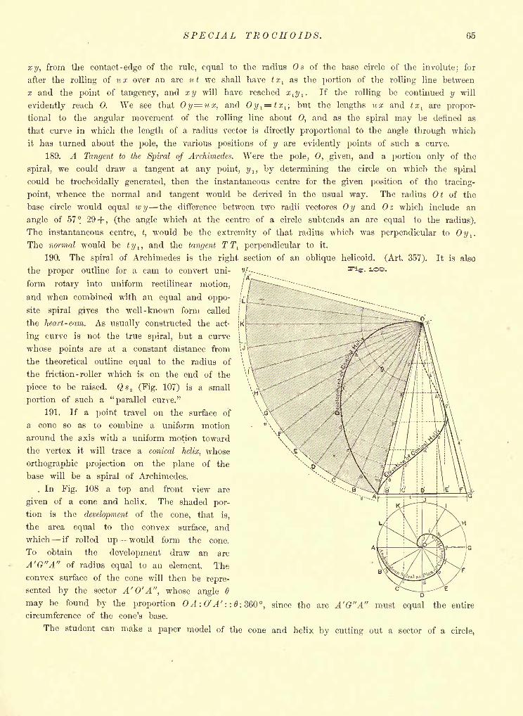
SPECIAL TROCHOIDS. 65
1OB.
xy, from the contact -edge of the rule, equal to the radius Os of the base circle of the involute; for
after the rolling of ux over an arc ut we shall have txl
as the portion of the rolling line between
x and the point of tangency, and xy will have reached xl y l
. If the rolling be continued y will
evidently reach 0. We see that Oy= ux, and Oy l= tx
l ;but the lengths ux and tx
lare propor-
tional to the angular movement of the rolling line about 0, and as the spiral may be defined as
that curve in which the length of a radius vector is directly proportional to the angle through which
it has turned about the pole, the various positions of y are evidently points of such a curve.
189. A Tangent to the Spiral of Archimedes. Were the pole, 0, given, and a portion only of the
spiral, we could draw a tangent at any point, y , , by determining the circle on which the spiral
could be trochoidally generated, then the instantaneous centre for the given position of the tracing-
point, whence the normal and tangent would be derived in the usual way. The radius Ot of the
base circle would equal wy the difference between two radii vectores Oy and Oz which include an
angle of 57 29+, (the angle which at the centre of a circle subtends an arc equal to the radius).
The instantaneous centre, t,would be the extremity of that radius which was perpendicular to Oy l
.
The normal would be ty r ,and the tangent TT
l perpendicular to it.
190. The spiral of Archimedes is the right section of an oblique helicoid. (Art. 357). It is also
the proper outline for a cam to convert uni-
form rotary into uniform rectilinear motion,
and when combined with an equal and oppo-
site spiral gives the well-known form called
the heart -cam. As usually constructed the act-
ing curve is not the true spiral, but a curve
whose points are at a constant distance from
the theoretical outline equal to the radius of
the friction -roller which is on the end of the
piece to be raised. Qs 2 (Fig. 107) is a small
portion of such a "parallel curve."
191. If a point travel on the surface of
a cone so as to combine a uniform motion
around the axis with a uniform motion toward
the vertex it will trace a conical helix, whose
orthographic projection on the plane of the
base will be a spiral of Archimedes.
. In Fig. 108 a top and front view are
given of a cone and helix. The shaded por-
tion is the development of the cone, that is,
the area equal to the convex surface, and
which if rolled up would form the cone.
To obtain the development draw an arc
A'G"A" of radius equal to an element. The
convex surface of the cone will then be repre-
sented by the sector A'O'A", whose angle 6
may be found by the proportion OA: ff A'::
circumference of the cone's base.
The student can make a paper model of the cone and helix by cutting out a sector of a circle,
61:360, since the arc A'G"A" must the entire
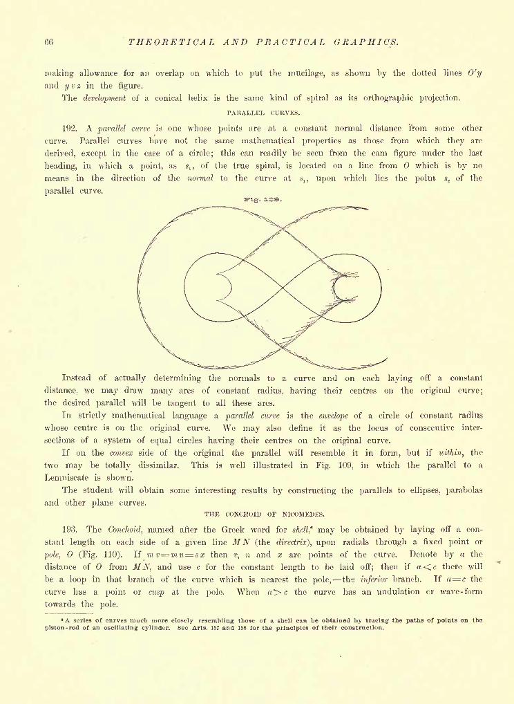
66 THEORETICAL AND PRACTICAL GRAPHICS.
making allowance for an overlap on which to put the mucilage, as shown by the dotted lines O'y
and y v z in the figure.
The development of a conical helix is the same kind of spiral as its orthographic projection.
PARALLEL CURVES.
192. A parallel curve is one whose points are at a constant normal distance 'from some other
curve. Parallel curves have not the same mathematical properties as those from which they are
derived, except in the case of a circle; this can readily be seen from the cam figure under the last
heading, in which a point, as ,, of the true spiral, is located on a line from which is by no
means in the direction of the normal to the curve at ,, upon which lies the point s2 of the
parallel curve.
Instead of actually determining the normals to a curve and on each laying off a constant
distance, we may draw many arcs of constant radius, having their centres on the original curve;
the desired parallel will be tangent to all these arcs.
In strictly mathematical language a parallel curve is the envelope of a circle of constant radius
whose centre is on the original curve. We may also define it as the locus of consecutive inter-
sections of a system of equal circles having their centres on the original curve.
If on the convex side of the original the parallel will resemble it in form, but if within, the
two may be totally dissimilar. This is well illustrated in Fig. 109, in which the parallel to a
Lemniscate is shown.
The student will obtain some interesting results by constructing the parallels to ellipses, parabolas
and other plane curves.
THE CONCHOID OF NICOMEDES.
193. The Conchoid, named after the Greek word for shell* may be obtained by laying off a con-
stant length on each side of a given line M'N (the directrix), upon radials through a fixed point or
pole, (Fig. 110). If imv=mn=8x then v, n and x are points of the curve. Denote by a the
distance of from MN, and use c for the constant length to be laid off; then if a<c there will
be a loop in that branch of the curve which is nearest the pole, the inferior branch. If a= c the
curve has a point or cusp at the pole. When >c the curve has an undulation cr wave- form
towards the pole.
*A scries of curves much more closely resembling those of a shell can be obtained by tracing the paths of points on the
piston-rod of an oscillating cylinder. See Arts. 157 and 158 for the principles of their construction.
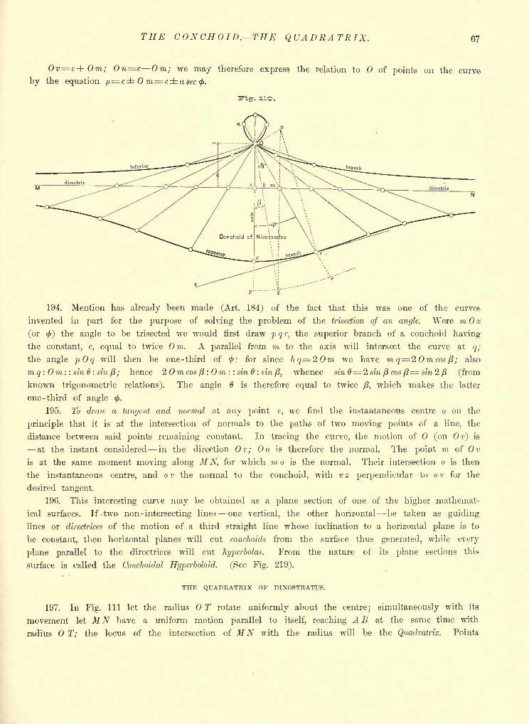
THE CONCHOID. THE QUADRATRIX. 67
Ov c+Om; On=c Om; we may therefore express the relation to of points on the curve
by the equation p= c m=casec<f>.
rig-, no.
194. Mention has already heen made (Art. 184) of the fact that this was one of the curves
invented in part for the purpose of solving the problem of the trisection of an angle. Were m x
(or <) the angle to be trisected we would first draw pqr, the superior branch of a conchoid having
the constant, c, equal to twice Om. A parallel from m to the axis will intersect the curve at q;
the angle pOq will then be one-third of <: for since bq=20m we have mg= 2 Omcos/3; also
mq : Om: : sin 6: sin/3; hence 2 Omcos/3: Om : : sin 6 : si?i/3, whence sin 6= 2 sin f3 cos (3= sin 2 (3 (from
known trigonometric relations). The angle 6 is therefore equal to twice /3, which makes the latter
one -third of angle <f>.
195. To draw a tangent and normal at any point v, we find the instantaneous centre o on the
principle that it is at the intersection of normals to the paths of two moving points of a line, the
distance between said points remaining constant. In tracing the curve, the motion of (on Ov) is
at the instant considered in the direction Ov; Oo is therefore the normal. The point m of Ov
is at the same moment moving along M N, for which mo is the normal. Their intersection o is then
the instantaneous centre, and o v the normal to the conchoid, with v z perpendicular to o v for the
desired tangent.
196. This interesting curve may be obtained as a plane section of one of the higher mathemat-
ical surfaces. If -two non- intersecting lines one vertical, the other horizontal be taken as guiding
lines or directrices of the motion of a third straight line whose inclination to a horizontal plane is to
be constant, then horizontal planes will cut conchoids from the surface thus generated, while every
plane parallel to the directrices will cut hyperbolas. From the nature of its plane sections this
surface is called the Conchoidal Hyperboloid. (See Fig. 219).
THE QUADRATRIX OF DINOSTRATUS.
197. In Fig. Ill let the radius T rotate uniformly about the centre; simultaneously with its
movement let MN have a uniform motion parallel to itself, reaching A B at the same time with
radius T; the locus of the intersection of MN with the radius will be the Quadratrix. Points
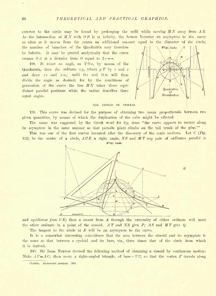
68 THEORETICAL AND PRACTICAL GRAPHICS.
exterior to the circle may be found by prolonging the radii while moving MN away from A B.
As the intersection of MN with OB is at infinity, the former becomes an asymptote to the curve
as often as it moves from the centre an additional amount equal to the diameter of the circle;
the number of branches of the Quadratrix may therefore
be infinite. It may be proved analytically that the curve
crosses A at a distance from equal to 2 r H- IT.
198. To trisect an angle, as T a, by means of the
Quadratrix, draw the ordinate ap, trisect p T by s and x
and draw 8 c and % m; radii c and m will then
divide the angle as desired: for by the conditions of
generation of the curve the line MN takes three equi-
distant parallel positions while the radius describes three
equal angles.
THE CISSOID OF DIOCLES.
199. This curve was devised for the purpose of obtaining two mean proportionals between two
given quantities, by means of which the duplication of the cube might be effected.
The name was suggested by the Greek word for ivy, since "the curve appears to mount along
its asymptote in the same manner as that parasite plant climbs on the tall trunk of the pine."*
This was one of the first curves invented after the discovery of the conic sections. Let C (Fig.
112) be the centre of a circle, ACE a right angle, NS and MT any pair of ordinates parallel to
and equidistant from CE; then a secant from A through the extremity of either ordinate will meet
the other ordinate in a point of the cissoid. A T and NS give P; A S and M T give Q.
The tangent to the circle at B will be an asymptote to the curve.
It is a somewhat interesting coincidence that the area between the cissoid and its asymptote is
the same as that between a cycloid and its base, viz., three times that of the circle from which
it is derived.
200. Sir Isaac Newton devised the following method of obtaining a cissoid by continuous motion:
Make AV=AC; then move a right-angled triangle, of base= V (7, so that the vertex F travels along
"Leslie. Geometrical Analysis. 1821.
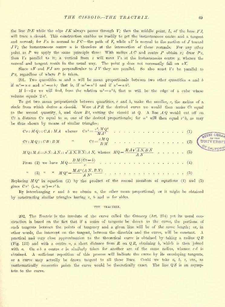
THE CISSOID. THE TRACTRIX. 69
the line DE while the edge JK always passes through V; then the middle point, L, of the base FJ,will trace a cissoid. This construction enables us readily to get the instantaneous centre and a tangent
and normal; for FH is normal to FC the path of F, while nV is normal to the motion of / toward
/ V; the instantaneous centre n is therefore at the intersection of these normals. For any other
point as P we apply the same principle thus : With radius A C and centre P obtain x; draw Px,
then Vz parallel to it; a vertical from x will meet Vz at the instantaneous centre y, whence the
normal and tangent result in the usual way. The point y does not necessarily fall on nV.
Since nV and FJ are perpendicular to J V they are parallel. So also must Vz be parallel to
Px, regardless of where P is taken.
201. Two quantities m and n will be mean proportionals between two other quantities a and b
if m*=na and n'*=mb; that is, if m 3= 26 and if n*=<ib 2
.
If 6= 2 a we will find, from the relation m'4= a'2
b, that m will be the edge of a cube whose
volume equals 2 a 3.
To get two mean proportionals between quantities, r and b, make the smaller, r, the radius of a
circle from which derive a cissoid. Were APR the derived curve we would then make Ct equal
to the second quantity, b, and draw Bt, cutting the cissoid at Q. A line A Q would cut off on
Ct a distance Cv equal to m, one of the desired proportionals; for m 3will then equal r'
!
b, as maybe thus shown by means of similar triangles:
r 3 MO 3
Cv: MQ::CA: MA whence Cv*= '
I,.?MA
Ct:MQ::CB:BM C=:-DnrrB M
M Q-.MA:: SX : A N : : /A N. BN:A N, whence MQ= MA ^AX.BN
From (2) we have J/Q= (4)r
(V K MA*(AN.BN)W Mty = . m -
(o;
Replacing M Q3 in equation (1) by the product of the second members of equations (4) and (5)
gives Cv 3
(i.e., m s
)= r
26.
By interchanging r and b we obtain n, the other mean proportional; or it might be obtained
by constructing similar triangles having r, b and m for sides.
THE TRACTRIX.
202. The Tractrix is the involute of the curve called the Catenary (Art. 214) yet its usual con-
struction is based on the fact that if a series of tangents be drawn to the curve, the portions of
such tangents between the points of tangency and a given line will be of the same length ; or, in
other words, the intercept on the tangent, between the directrix and the curve, will be constant. A
practical and very close approximation to the theoretical curve is obtained by taking a radius Q R
(Fig. 11.3) and with a centre a, a short distance from R on Q R, obtaining b, 'which is then joined
with a. On a b a centre c is similarly taken for another arc of the same radius, whence c d is
obtained. A sufficient repetition of this process will indicate the curve by its enveloping tangents,
or a curve may actually be drawn tangent to all these lines. Could we take, 6, c, etc., as
mathematically consecutive points the curve would be theoretically exact. The line QS is an asymp-
tote to the curve.
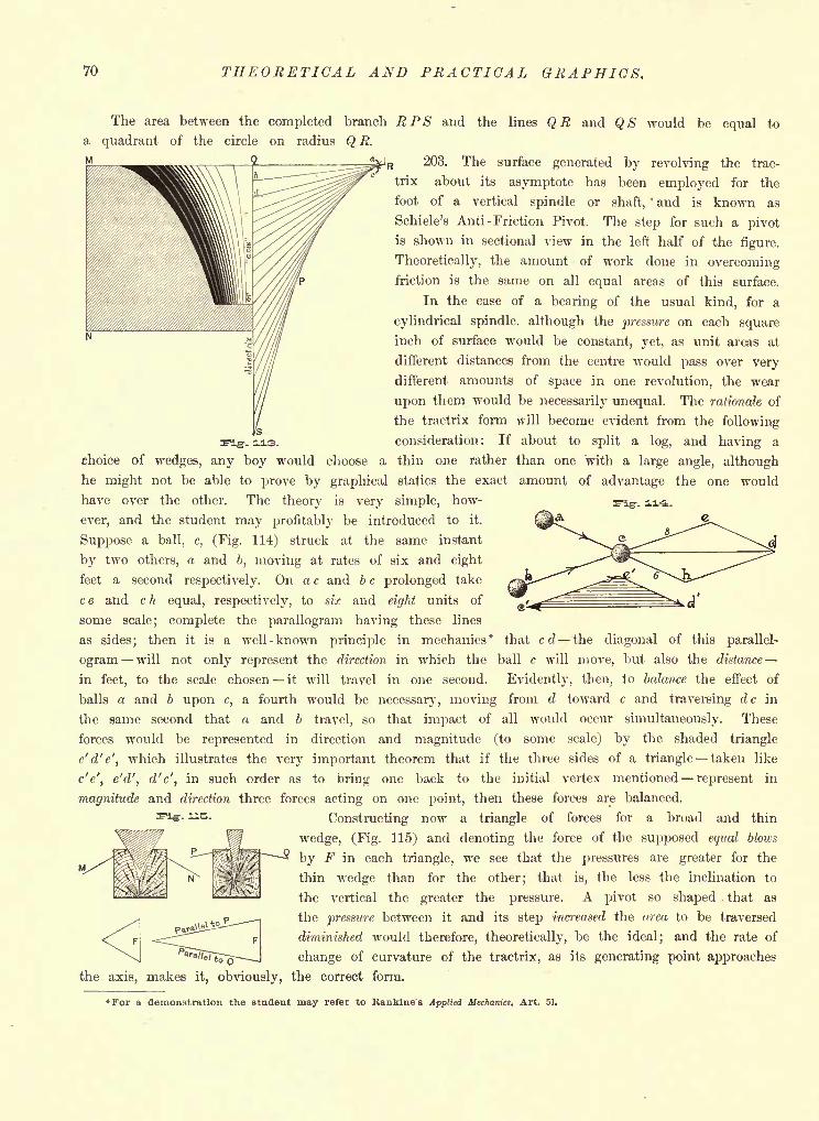
70 THEORETICAL AND PRACTICAL GRAPHICS.
The area between the completed branch RPS and the lines QR and QS would be equal to
a quadrant of the circle on radius Q R.
_2 i_o 203. The surface generated by revolving the trac-
trix about its asymptote has been employed for the
foot of a vertical spindle or shaft,' and is known as
Schiele's Anti- Friction Pivot. The step for such a pivot
is shown in sectional view in the left half of the figure.
Theoretically, the amount of work done in overcomingfriction is the same on all equal areas of this surface.
In the case of a bearing of the usual kind, for a
cylindrical spindle, although the pressure on each square
inch of surface would be constant, yet, as unit areas at
different distances from the centre would pass over very
different amounts of space in one revolution, the wear
upon them would be necessarily unequal. The rationale of
the tractrix form will become evident from the following
consideration: If about to split a log, and having a
choice of wedges, any boy would choose a thin one rather than one with a large angle, although
he might not be able to prove by graphical statics the exact amount of advantage the one would
have over the other. The theory is very simple, how-
ever, and the student may profitably be introduced to it.
Suppose a ball, c, (Fig. 114) struck at the same instant
by two others, a and b, moving at rates of six and eight
feet a second respectively. On a c and b c prolonged take
c e and c h equal, respectively, to six and eight units of
some scale; complete the parallogram having these lines
as sides; then it is a well-known principle in mechanics* that erf the diagonal of this parallel-
ogram will not only represent the direction in which the ball c will move, but also the distance
in feet, to the scale chosen it will travel in one second. Evidently, then, to balance the effect of
balls a and b upon c, a fourth would be necessary, moving from d toward c and traversing dc in
the same second that a and b travel, so that impact of all would occur simultaneously. These
forces would be represented in direction and magnitude (to some scale) by the shaded triangle
c'd'e', which illustrates the very important theorem that if the three sides of a triangle taken like
c'e', e'd', d'c', in such order as to bring one back to the initial, vertex mentioned represent in
magnitude and direction three forces acting on one point, then these forces are balanced.
Constructing now a triangle of forces for a broad and thin
wedge, (Fig. 115) and denoting the force of the supposed equal blows
by F in each triangle, we see that the pressures are greater for the
thin wedge than for the other; that is, the less the inclination to
the vertical the greater the pressure. A pivot so shaped that as
the pressure between it and its step increased the area to be traversed
diminished would therefore, theoretically, be the ideal; and the rate of
change of curvature of the tractrix, as its generating point approaches
the axis, makes it, obviously, the correct form.
rig-, us.
For a demonstration the student may refer to Hankine's Applied Mechanics, Art. 51.
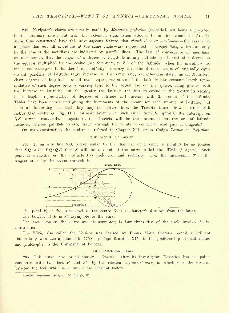
THE TRACTR IX WITCH OF AGNESI.-CARTESIAN OVALS. 71
204. Navigator's charts are usually made by Mercator's projection (so-called, not being a projection
in the ordinary sense, but with the extended signification alluded to in the remark in Art. 2).
Maps thus constructed have this advantageous feature, that rhumb lines or loxodromics the curves on
a sphere that cut all meridians at the same angle are represented as straight lines, which can only
be the case if the meridians are indicated by parallel lines. The law of convergence of meridians
on a sphere is, that the length of a degree of longitude at any latitude equals that of a degree on
the equator multiplied by the cosine (see foot-note, p. 31) of the latitude; when the meridians are
made non- convergent it is, therefore, manifestly necessary that the distance apart of originally equi-
distant parallels of latitude must increase at the same rate; or, otherwise stated, as on Mercator's
chart degrees of longitude are all made equal, regardless of the latitude, the constant length repre-
sentative of such degree bears a varying ratio to the actual arc on the sphere, being greater with
the increase in latitude; but the greater the latitude the less its cosine or the greater its secant;
hence lengths representative of degrees of latitude will increase with the secant of the latitude.
Tables have been constructed giving the increments of the secant for each minute of latitude; but
it is an interesting fact that they may be derived from the Tractrix thus: Draw a circle with
radius Q R, centre Q (Fig. 113); estimate latitude on such circle from R upward; the intercept on
QS between consecutive tangents to the Tractrix will be the increment for the arc of latitude
included between parallels to QS, drawn through the points of contact of said pair of tangents."
On map construction the student is referred to Chapter XII, or to Craig's Treatise on Projections.
THE WITCH OF AGNESI.
205. If on any line S Q, perpendicular to the diameter of a circle, a point S be so located
that S Q: A B ::PQ: Q B then .S will be a point of the curve called the Witch of Agnesi. Such
point is evidently on the ordinate P Q prolonged, and vertically below the intersection T of the
tangent at A by the secant through P.
The point E, at the same level as the centre 0, is a diameter's distance from the latter.
The tangent at B is an asymptote to the curve.
The area between the curve and its asymptote is four times that of the circle involved in its
construction.
The Witch, also called the Versiera, was devised by Donna Maria Gaetana Agnesi, a brilliant
Italian lady who was appointed in 1750, by Pope Benedict XIV, to the professorship of mathematics
and philosophy in the University of Bologna.
THE CARTESIAN OVAL.
206. This curve, also called simply a Cartesian, after its investigator, Descartes, has its points
connected with two foci, F' and F", by the relation m p'dtr.n p" =k c, in which c is the distance
between the foci, while m, n and k are constant factors.
Leslie. Geometrical Analysis. Edinburgh, 1821.
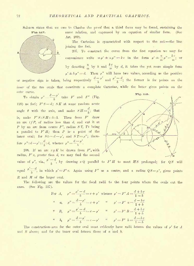
72 THEORETICAL AND PRACTICAL GRAPHICS.
Salmon states that we owe to Chasles the proof that a third focus may be found, sustaining the
same relation, and expressed by an equation of similar form. (See
Art. 209).
The Cartesian is symmetrical with respect to the axis the line
joining the foci.
207. To construct the curve from the first equation we may for
convenience write mp'np" = kc in the form p' p"--"-- or
by denoting-'-
by b and "-
by d, it takes the yet more simple form
p'bp"= d. Then p" will have two values, according as the positive
or negative sign is taken, being respectively 5- and , ;the former is for points on the
inner of the two ovals that constitute a complete Cartesian, while the latter gives points on the
outer curve.
To obtain p" = '^ P- take F' and F" (Fig.
-. ne.
118) as foci; F'S=d; SK at some random acute
angle with the axis, and make SH=^; that
is, make F' S: SH: : b : 1. Then from F' draw
an arc tfP, of radius less than d, and cut it at
P by an arc from centre F", radius S T, Tt being
a parallel to F' H; then P is- a point of the
inner oval; for 8t=d p', and ST=p"; there-
fore p":d p' : : .: d, whence p"- :-*.
208. If an arc xyK be drawn from F',with
radius, F' x, greater than d, we may find the second
value of p", viz.,p -
, by drawing xQ parallel to F' H to meet HS prolonged; for QS will
equal! T ,
in which p'= F'x. Again using F" as a centre, and a radius QS= p", gives points
R and M of the larger oval.
The following are the values for the focal radii to the four points where the ovals cut the
axes. (See Fig. 117).
For A, p" ='L^=c + p' whence P' = F'A = d + b
B,
d- P'
d b c
(I + b c
1 +bd be
b "16The construction - arcs for the outer oval must evidently have radii between the values of p' for A
and B above; and for the inner oval between those of a and b.
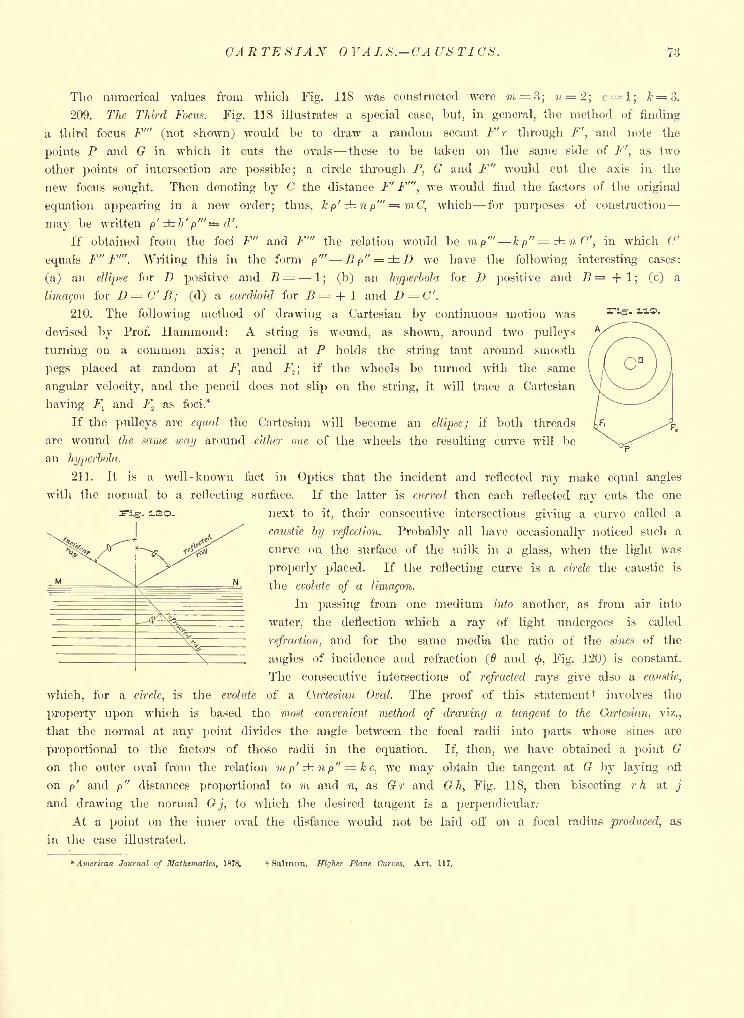
CA R TE S IAN VA L S. CA US TICS. 73
The numerical values from which Fig. 118 was constructed were m = 3; n=2; c= l; k = 3.
209. The Third Focus. Fig. 118 illustrates a special case, but, in general, the method of finding
a third focus F'" (not shown) would be to draw a random secant F' r through F', and note the
points P and G in which it cuts the ovals these to be taken on the same side of F'',
as two
other points of intersection are possible; a circle through P, G and F" would cut the axis in the
new focus sought. Then denoting by C the distance F' F'", we would find the factors of the original
equation appearing in a new order; thus, kp'np'" = mC, which for purposes of construction
may be written p'b'p'"=d'.If obtained from the foci F" and F'" the relation would be m p'" kp"-= n C', in which C'
equals F" F"'. Writing this in the form p"' Bp" = D we have the following interesting cases:
(a) an ellipse for D positive and B - 1; (b) an hyperbola for D positive and R = + 1
; (c) a
lima^on for D = C' B ; (d) a cardioid for B - + 1 and Z) = C".
210. The following method of drawing a Cartesian by continuous motion was
devised by Prof. Hammond: A string is wound, as shown, around two pulleys
turning on a common axis; a pencil at P holds the string taut around smooth
pegs placed at random at Fl
and F^; if the wheels be turned with the same
angular velocity, and the pencil does not slip on the string, it will trace a Cartesian
having Ftand F.
fas foci.*
If the pulleys are equal the Cartesian will become an ellipse; if both threads
are wound the same way around either one of the wheels the resulting curve will be
an hyperbola.
211. It is a well -known fact in Optics that the incident and reflected ray make equal angles
with the normal to a reflecting surface. If the latter is curved then each reflected ray cuts the one
next to it, their consecutive intersections giving a curve called a
caustic by reflection. Probably all have occasionally noticed such a
curve on the surface of the milk in a glass, when the light was
properly placed. If the reflecting curve is a circle the caustic is
the evolute of a limagon.
In passing from one medium into another, as from air into
water, the deflection which a ray of light undergoes is called
refraction, and for the same media the ratio of the sines of the
angles of incidence and refraction (0 and <, Fig. 120) is constant.
The consecutive intersections of refracted rays give also a caustic,
which, for a circle, is the evolute of a Cartesian Oval. The proof of this statement t involves the
property upon which is based the most convenient method of drawing a tangent to the Cartesian, viz.,
that the normal at any point divides the angle between the focal radii into parts whose sines are
proportional to the factors of those radii in the equation. If, then, we have obtained a point G
on the outer oval from the relation m p' n p" -=kc, we may obtain the tangent at G by laying off
on p' and p" distances proportional to m and n, as Gr and G h, Fig. 118, then bisecting rh at_;'
and drawing the normal Gj, to which the desired tangent is a perpendicular.-
At a point on the inner oval the distance would not be laid off on. a focal radius produced, as
in the case illustrated.
. iso.
*-"'--*
* American Journal of Mathematics, 1878. f Salmon. Higher Plane Curves. Art. 117.

74 THEORETICAL AND PRACTICAL GRAPHICS.
CASSIAN OVALS.
212. In the Cassian Ovals or Ovals of Cassini the points are connected with two foci by the
relation p'p" = k 2
, i.e., the product of the focal radii is equal to some perfect square. These curves
have already been alluded to in Art. 114 as plane sections of the annular torus, taken parallel to
its axis.
- 121.
-. 122.
In Art. 158 one form the Lemniscate receives special treatment. For it the constant P must
equal w 2
,the square of half the distance between the foci. When k is less than m, the curve
becomes two separate ovals.
213. The general construction depends on the fact that in any semicircle the square of an ordinate
equals the product of the segments into which it divides the diameter. In Fig. 122 take Fland
F2
as the foci, erect a perpendicular F1S to the axis
Fl FZ ,
and on it lay off FlR equal to the constant, k.
Bisect FlF
tat and draw a semicircle of radius OR.
This cuts the axis at A and B, the extreme points of
the curve; for k t=FlAxF
1B. Any other point T
may be obtained by drawing from Fl
a circular arc of
radius F^ t greater than FtA ; draw t R, then R x perpen-
dicular to it; xFl
will then be the p", and Flt the p', for
four points of the curve, which will be at the intersection of
arcs struck from Fland F
tas centres and with those radii.
To get a normal at any point T draw T, then make angle
the desired line.
^e^F.T 0; Ts will be
THE CATENARY.
214. If a flexible chain, cable or string, of uniform weight per unit of length, be freely sus-
pended by its extremities, the curve which it takes under the action of gravity is called a Catenary,
from catena, a chain.
A simple and practical method of obtaining a catenary on the drawing-board, would be to insert
two pins in the board, in the desired relative position of the points of suspension, and then attach
to them a string of the desired length. By holding the board vertically, the string would assume
the catenary, whose points could then be located with the pencil and joined in the usual manner
with the irregular curve. Otherwise, if its points are to be located by means of an equation, we
take axes in the plane of the curve, the y-axis (Fig. 123) being a vertical line through the lowest
point T of "the catenary, while the x-axis is a horizontal line at a distance m below T. The quan-
tity m is called the parameter of the curve, and is equal to the length of string which represents
the tension at the lowest point.
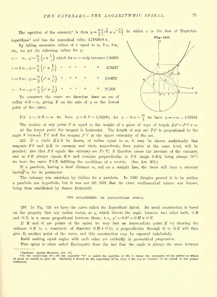
THE CATENARY. THE LOGARITHMIC SPIRAL. 75
The equation of the catenary1
is thenj/=.^e + e
)in which e is the base of Napierian
logarithms2 and has the numerical value 2.7182818 +.
By taking successive values of x equal to m, 2 771, 3 m,
etc., we get the following values for y.
x= m...y=-^\e-\ )which for m = unity becomes 1.54308
t \ & f
' ; " " " "3.76217
" " " " "10.0676
" " " " "27.308
To construct the curve we therefore draw an arc of
radius B= m, giving T on the axis of y as the lowest
point of the curve.
For x =05 = 771 we have y =B P 1.54308; for x = a = ^ we have y = a n 1.03142.
The tension at any point P is equal to the weight of a piece of rope of length B P= P C + m.
At the lowest point the tangent is horizontal. The length of any arc TP is proportional to the
angle 6 between T C and the tangent P V at the upper extremity of the arc.
215. If a circle RLE be drawn, of radius equal to m, it may be shown analytically that
tangents PS and QR, to catenary and circle respectively, from points at the same level, will be
parallel: also that PS equals the catenary -arc Pr T; S therefore traces the involute of the catenary,
and as S B always equals R and remains perpendicular to PS (angle R Q being always 90 )
we have the curve TSK fulfilling the conditions of a tractrix. (See Art. 202.)
If a parabola, having a focal distance m, roll on a straight line, the focus will trace a catenary
having m for its parameter.
The catenary was mistaken by Galileo for a parabola. In 1669 Jungius proved it to be neither
a parabola nor hyperbola, but it was not till 1691 that its exact mathematical nature was known,
being then established by James Bernouilli.
THE LOGARITHMIC OR EQUIANGULAR SPIRAL.
216. In Fig. 124 we have the curve called the Logarithmic Spiral. Its usual construction is based
on the property that any radius vector, as p, which bisects the angle between two other radii, OMand ON, is a mean proportional between them; i.e., p
2 = S 2= M x N.
If M and G are points of the spiral we may find an intermediate point K by drawing the
ordinate OK to a semicircle of diameter OM+OG; a perpendicular through G to G K will then
give D, another point of the curve, and this construction may be repeated indefinitely.
Radii making equal angles with each other are evidently in geometrical progression.
This spiral is often called Equiangular from the fact that the angle is always the same between
1 Rankine. Applied Mechanics. Art. 175.
sin the expression 102 = 100 the quantity "2" is called the logarithm of 100, It being the exponent of the power to which10 must be raised to give 100. Similarly 2 would be the logarithm of 64, were 8 the base or number to be raised to the powerindicated.
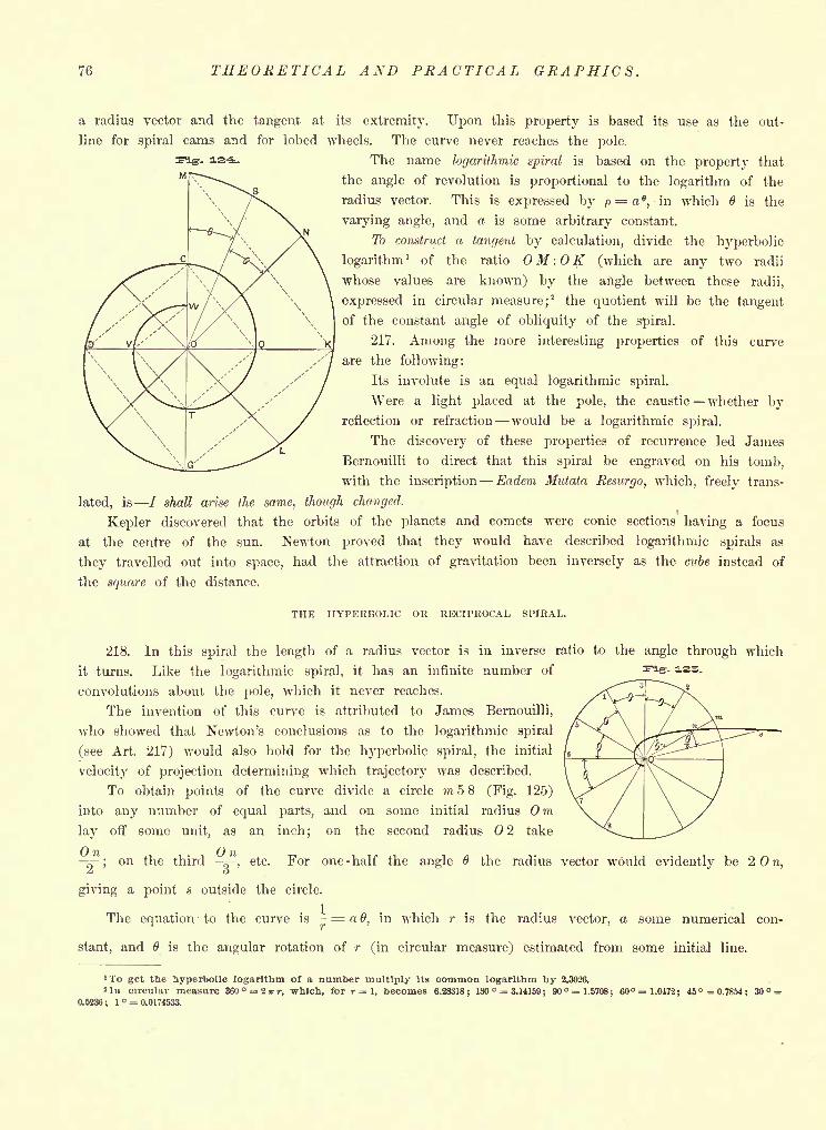
76 THEORETICAL AND PRACTICAL GRAPHICS.
a radius vector and the tangent at its extremity. Upon this property is based its use as the out-
line for spiral cams and for lobed wheels. The curve never reaches the pole.
The name logarithmic spiral is based on the property that
the angle of revolution is proportional to the logarithm of the
radius vector. This is expressed by p = a e,in which 6 is the
varying angle, and a is some arbitrary constant.
To construct a tangent by calculation, divide the hyperbolic
logarithm1 of the ratio M : K (which are any two radii
whose values are known) by the angle between these radii,
expressed in circular measure;2 the quotient will be the tangent
of the constant angle of obliquity of the spiral.
217. Among the more interesting properties of this curve
are the following:
Its involute is an equal logarithmic spiral.
Were a light placed at the pole, the caustic whether byreflection or refraction would be a logarithmic spiral.
The discovery of these properties of recurrence led James
Bernouilli to direct that this spiral be engraved on his tomb,
with the inscription Eadem Mutata Resurgo, which, freely trans-
lated, is / shall arise the same, though changed.
Kepler discovered that the orbits of the planets and comets were conic sections having a focus
at the centre of the sun. Newton proved that they would have described logarithmic spirals as
they travelled out into space, had the attraction of gravitation been inversely as the cube instead of
the square of the distance.
THE HYPERBOLIC OR RECIPROCAL SPIRAL.
218. In this spiral the length of a radius vector is in inverse ratio to the angle through which
it turns. Like the logarithmic spiral, it has an infinite number of
convolutions about the pole, which it never reaches.
The invention of this curve is attributed to James Bernouilli,
who showed that Newton's conclusions as to the logarithmic spiral
(see Art. 217) would also hold for the hyperbolic spiral, the initial
velocity of projection determining which trajectory was described.
To obtain points of the curve divide a circle m58 (Fig. 125)
into any number of equal parts, and on some initial radius Omlay off some unit, as an inch
;on the second radius 2 take
On Onc-
;on the third ^-, etc. For one - half the angle 6 the radius vector would evidently be 2 n,Z o
giving a point s outside the circle.
The equation to the curve is- = a 6, in which r is the radius vector, a some numerical con-
stant, and 6 is the angular rotation of r (in circular measure) estimated from some initial line.
. 12S-
'To get the hyperbolic logarithm of a number multiply its common logarithm by 2.3026.
ln circular measure 360 = 2irr, which, for r = l, becomes 6.28318; 180 = 3.14159;90 = 1.5708; 60 = 1.0472; 45 =0.7854; 30 =
0.5236; 1 o = 0.0174533.
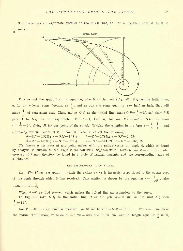
THE HYPERBOLIC SPIRAL. THE LITUUS. 77
The curve has an asymptote parallel to the initial line, and at a distance from it equal to
units,a
To construct the spiral from its equation, take as the pole (Fig. 26); Q as the initial line;
a, for convenience, some fraction, as;and as our unit some quantity, say half an inch, that will
make --of convenient size. Then, taking Q as the initial line, make P= = 2", and draw PRd (I
parallel to OQ for the asymptote. For 6= 1, that is, for arc KH= radius OH, we have
r = = 2", giving H for one point of the spiral. Writing the equation in the form r=,and
Ut GJ
expressing various values of in circular measure we get the following :
6= 30 = 0.5236; r= OM=Z'.'8 + : 6= 45 = 0.7854; r=0JV=2'/55;= 90 = 1.5708; r= OS= l'."2+: 6=180 = 3.14159; r=OT=.6366, etc.
The tangent to the curve at any point makes with the radius vector an angle <, which is found
by analysis to sustain to the angle 6 the following trigonometrical relation, tun < = #; the circular
measure of may therefore he found in a table of natural tangents, and the corresponding value of
<j> obtained.
THE LITUUS. THE IONIC VOLUTE.\
219. The Lituus is a spiral in which the radius vector is inversely proportional to the square root
of the angle through which it has revolved. This relation is shown by the equation r = -=,
alsoa\/@
written a 2 6= -=-r
1 -
When 6= we find r= oo,which makes the initial line an asymptote to the curve.
In Fig. 127 take Q as the initial line, as the pole, a = 2, and as our unit 3";
then
For = 90=7r (in circular measure 1.5708) we have r = OM=l". 2 +. For 6 = 1 we have
the radius T making an angle of 57. 29 + with the initial line, and in length equal to -units,
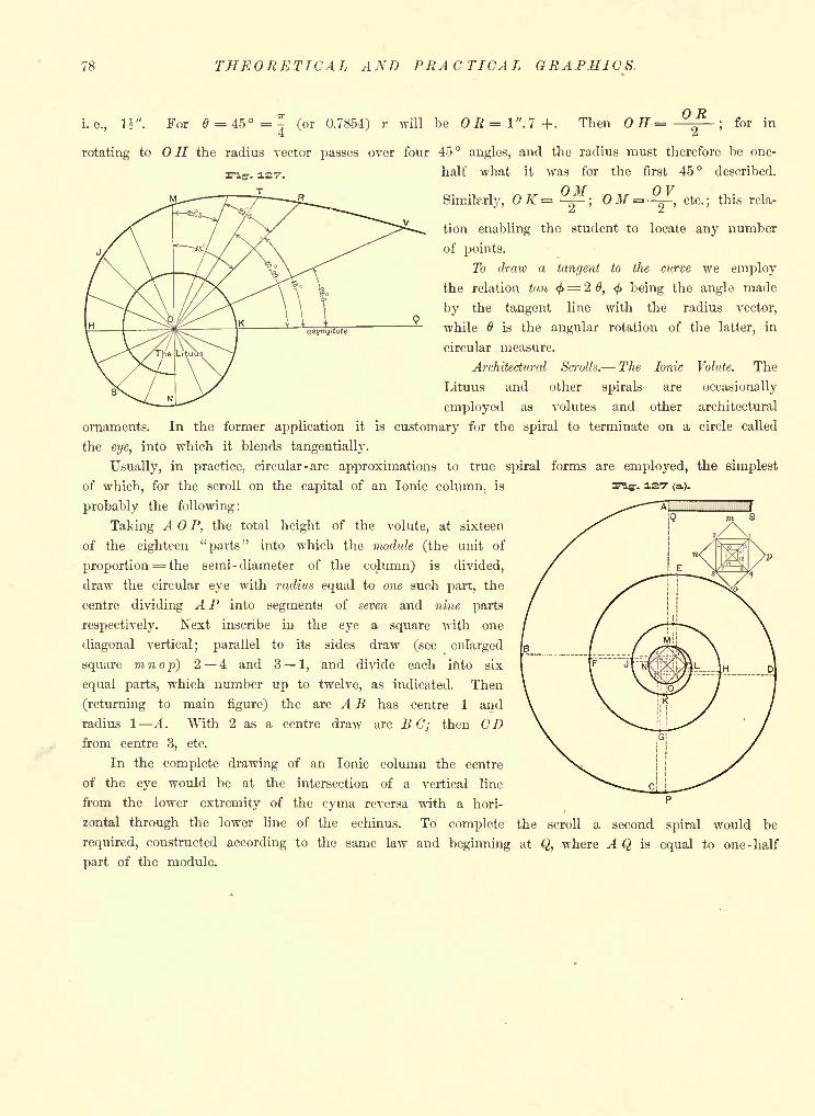
78 THEORETICAL AND PRACTICAL GRAPHICS,
for ini. e., li". For 6=45=-. (or 0.7854) r will be OR=1".7+. Then H =4
rotating to OH the radius vector passes over four 45 angles, and the radius must therefore be one-
half what it was for the first 45 described.
Similarly, QK= -;OM = --5-, etc.; this rela-
^ ^j
tion enabling the student to locate any number
of points.
To draw a tangent to the curve we employ
the relation tan <f>= 2 0, <f> being the angle made
by the tangent line with the radius vector,
while 6 is the angular rotation of the latter, in
circular measure.
Architectural Scrolls. The Ionic Volute. The
Lituus and other spirals are occasionally
employed as volutes and other architectural
ornaments. In the former application it is customary for the spiral to terminate on a circle called
the eye, into which it blends tangentially.
Usually, in practice, circular -arc approximations to true spiral forms are employed, the simplest
of which, for the scroll on the capital of an Ionic column, is
probably the following:
Taking A P, the total height of the volute, at sixteen
of the eighteen "parts" into which the module (the unit of
proportion = the semi -diameter of the column) is divided,
draw the circular eye with radius equal to one such part, the
centre dividing A P into segments of seven and nine parts
respectively. Next inscribe in the eye a square with one
diagonal vertical; parallel to its sides draw (see enlarged
square inn op) 2 4 and 3 1, and divide each into six
equal parts, which number up to twelve, as indicated. Then
(returning to main figure) the arc A B has centre 1 and
radius 1 A. With 2 as a centre draw arc BC; then CDfrom centre 3, etc.
In the complete drawing of an Ionic column the centre
of the eye would be at the intersection of a vertical line
from the lower extremity of the cyma reversa with a hori-
zontal through the lower line of the echinus. To complete the scroll a second spiral would be
required, constructed according to the same law and beginning at Q, where A Q is equal to one -half
part of the module.
-. 127 (a).
BRUSH TINTING AND SHADING. 79
CHAPTER VI.
TINTING PLAT AND GBADUATED. MASONRY, TILING, WOOD GRAINING, RIVER-BEDS ANDOTHER SECTIONS, WITH BRUSH ALONE OR IN COMBINED BRUSH AND LINE WORK.
220. Brush-work, with ink or colors, is either flat or graduated. The former gives the effect of
a flat surface parallel to the paper on which the drawing is made, while graded tints either show
curvature, or if indicating flat surfaces represent them as inclined to the paper, i.e., to the plane
of projection. For either, the paper should be, as previously stated (Arts. 41 and 44) cold-pressed and
stretched.
The surface to be tinted should not be abraded by sponge, knife or rubber.
221. The liquid employed for tinting must be free from sediment; or at least the latter, if
present, must be allowed to settle, and the brush dipped only in the clear portion at the top. A Tints
may, therefore, best be mixed in an artist's water-glass, rather than in anything shallower. In case
of several colors mixed together, however, it would be necessary to thoroughly stir up the tint each
time before taking a brushful.
A tint prepared from a cake of high-grade India ink is far superior to any that can be made
by using the ready-made liquid drawing inks.
222. The size of brush should bear some relation to that of the surface to be tinted; large
brushes for large surfaces and vice versa-^* The customary error of beginners is to use too small and
too dry a brush for tinting, and the reverse for shading.
223. Harsh outlines are to be avoided in brush work, especially in handsomely shaded drawings,
in which, if sharply defined, they would detract from the general effect. This will become evident
on comparing the spheres in Figs. 1 and 4 of Plate II.
Since tinting and shading can be successfully done, after a little practice, with only pencilled
limits, there is but little excuse for inking the boundaries; ftytljf, for the sake of definiteness, the
outlines are inked ** aH- it should be before the tinting, and in the finest of lines, preferably of
Tik; although -any 4nk- will do - provided \ soft sponge and plenty of clean water fee- Oj"
applied to remove any excess that will "run." The sponge is also to be the main reliance ef---the-
for the correction of errors in brush work; the water, however, and not the friction to
be the active agent. An entire tint may be removed in this way in case it seems desirable.
224. When beginning work incline the board at a small angle, so that the tint will flow down
after the brush. For a flat, that is, a uniform tint, start at the upper outline of the surface to be
covered, and with a brush full, yet not surcharged which would prevent its coming to a good point
pass lightly along from left to right, and on the return carry the tint down a little farther, making
short, quick strokes, with the brush held almost perpendicular to the paper. Advance the tint as
evenly as possible along a horizontal line^ wort? q"rrrck4y-__6fft<;ei outlines, but more slowly along
outlines, as one) should ; never overrun th^ latter and then resort to"trimming
"to conceal lack of
skill. It~"ls possible for any one, with care' and practice, to tint to yet not over boundaries.
-t- The advancing edge of the tint must not be allowed to dry until the lower boundary is reached.
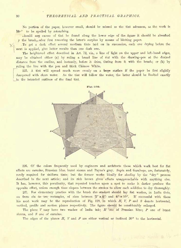
80 THEORETICAL AND PRACTICAL GRAPHICS.
No portion of the paper, however small, should be missed as the tint advances, as the work is
lit"1
to be spoiled by retouching.
uhould an$ excess of tint be found along the lower edge of the figure it should be absorbed
y the brush,, after first removing the latter's surplus by means of blotting paper.
-To get a dark effect several medium tints laid on in succession, each one drying before the
next is applied, give better results than one dark one.
The heightened effect described in Art. 72, viz., a line of light on the upper and left-hand edges,
may be obtained either (a) by ruling a broad line of tint with the drawing-pen at the desired
distance from the outline, and instantly, before it dries, tinting from it with the brush; or (b) by
ruling the line with the pen and thick Chinese White.
225. A tint will spread much more evenly on a tefge surface if the paper be first slightly
dampened with clean water. As the tint will follow the water, the latter should be limited exactly
_ to the intended outlines of the final tint.
-. 3.3S.
226. Of the colors frequently used by engineers and architects those which work best for flat
effects are carmine, Prussian blue, burnt sienna and Payne's gray. Sepia and Gamboge, are, fortunately,
rarely required for uniform tints; but the former works ideally for shading by the "dry" process
described in the next article; and its rich brown gives effects unapproachable with anything else.
It has, however, this peculiarity, that repeated touches upon a spot to make it darker produce the
opposite effect, unless enough time elapses between the strokes to allow each addition to dry thoroughly.
227. For elementary practice with the brush the student should lay flat washes, in India tints,
on from- six 4e- "ten -
rectangles, of sizes between ^J-" X$" and &^-X 10". If successful with these
his next work may be the reproduction of Fig. 128, in which H, V, P and S denote horizontal,
vertical, profile and section planes respectively. The figure should be considerably enlarged.
The plane V may have two washes of India ink; H one of Prussian blue; P one of burnt
sienna, and S one of carmine.
The edges of the planes H, V and P are either vertical or inclined 30 to the horizontal.
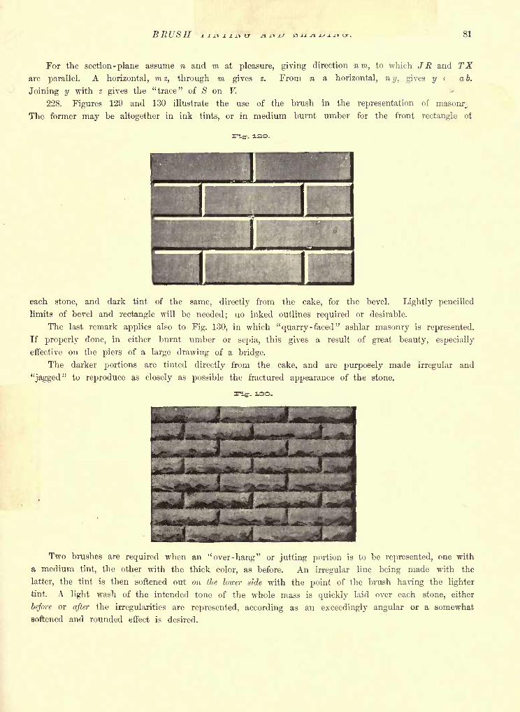
BRUSH 81
For the section -plane assume n and m at pleasure, giving direction nm, to which JR and
are parallel. A horizontal, mz, through m gives z. From w a horizontal, ny, gives ?/< ab.
Joining y with z gives the "trace" of S on V.
228. Figures 129 and 130 illustrate the use of the brush in the representation of masonr,
The former may be altogether in ink tints, or in medium burnt umber for the front rectangle ol
each stone, and dark tint of the same, directly from the cake, for the bevel. Lightly pencilled
limits of bevel and rectangle will be needed; no inked outlines required or desirable.
The last remark applies also to Fig. 130, in which "quarry -faced" ashlar masonry is represented.
If properly done, in either burnt umber or sepia, this gives a result of great beauty, especially
effective on the piers of a large drawing of a bridge.
The darker portions are tinted directly from the cake, and are purposely made irregular and
"jagged" to reproduce as closely as possible the fractured appearance of the stone.
-- ISO.
Two brushes are required when an ''over -hang" or jutting portion is to be represented, one with
a medium tint, the other with the thick color, as before. An irregular line being made with the
latter, the tint is then softened out on the lower side with the point of the brush having the lighter
tint. A light wash of the intended tone of the whole mass is quickly laid over each stone, either
before or after the irregularities are represented, according as an exceedingly angular or a somewhat
softened and rounded effect is desired.
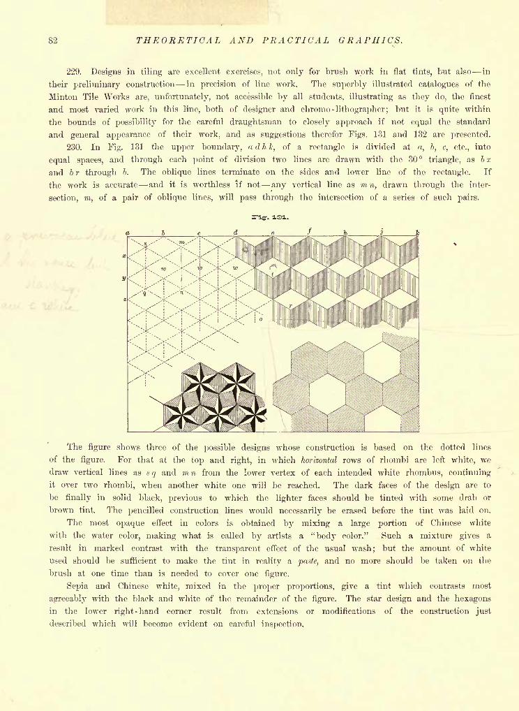
82 THEORETICAL AND PRACTICAL GRAPHICS.
229. Designs in tiling are excellent exercises, not only for brush work in flat tints, but also in
their preliminary construction in precision of line work. The superbly illustrated catalogues of the
Minton Tile Works are, unfortunately, not accessible by all students, illustrating as they do, the finest
and most varied work in this line, both of designer and chromo-lithographer; but it is quite within
the bounds of possibility for the careful draughtsman to closely approach if not equal the standard
and general appearance of their work, and as suggestions therefor Figs. 131 and 132 are presented.
230. In Fig. 131 the upper boundary, a d h k, of a rectangle is divided at a, b, c, etc., into
equal spaces, and through each point of division two lines are drawn with the 30 triangle, as bx
and b r through b. The oblique lines terminate on the sides and lower line of the rectangle. If
the work is accurate and it is worthless if not any vertical line as mn, drawn through the inter-
section, m, of a pair of oblique lines, will pass through the intersection of a series of such pairs.
The figure shows three of the possible designs whose construction is based on the dotted lines
of the figure. For that at the top and right, in which horizontal rows of rhombi are left white, we
draw vertical lines as s q and m n from the lower vertex of each intended white rhombus, continuing
it over two rhombi, when another white one will be reached. The dark faces of the design are to
be finally in solid black, previous to which the lighter faces should be tinted with some drab or
brown tint. The pencilled construction lines would necessarily be erased before the tint was laid on.
The most opaque effect in colors is obtained by mixing a large portion of Chinese white
with the water color, making what is called by artists a "body color." Such a mixture gives a
result in marked contrast with the transparent effect of the usual wash; but the amount of white
used should be sufficient to make the tint in reality a paste, and no more should be taken on the
brush at one time than is needed to cover one figure.
Sepia and Chinese white, mixed in the proper proportions, give a tint which contrasts most
agreeably with the black and white of the remainder of the figure. The star design and the hexagons
in the lower right-hand corner result from extensions or modifications of the construction just
described which will become evident on careful inspection.
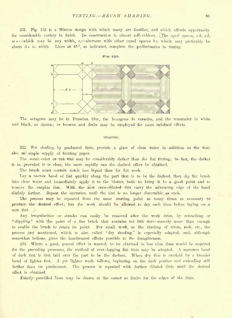
TINTING. BRUSH SHADING. 83
231. Fig. 132 is a Minton design with which many are familiar, and which affords opportunity
for considerable variety in finish. Its construction is almost self-evident. (The equal spaces, a b, cd,
mn which may be any width, x, alternate with other equal spaces be, which may preferably be
about 3 x in width. Lines at 45,
as indicated, complete the preliminaries to tinting.
. 132.
The octagons may be in Prussian blue, the hexagons in carmine, and the remainder in white
and black, as shown; or browns and drabs may be employed for more subdued effects.
SHADING.
232. For shading, by graduated tints, provide a glass of clear water m addition to the tint;
also ato' ample supply of blotting paper.
The water -color or- ink tint may be considerably darker than for flat tinting; m-4ac4, the darker
4t--isy -provided it is clear, the more rapidly can the desired effect be obtained.
The brush must contain much less liquid than for flat work.
Lay a narrow band of tint quickly along the part that is to be the darkest, then dip the brush
into clear water and immediately apply it to the blotter, both to bring it to a good point and to
remove the surplus tint. With the j)ow once -diluted tint carry the advancing edge of the band
slightly farther. Repeat the operation until the tint is no longer discernible as such.
The process may be repeated from the same starting point as many times as necessary to
produce the desired effect; but the work should T>e allowed to dry each time before laying on a
new tint.
Any irregularities or streaks can easily be removed after the work dries, by retouching or
"stippling" with the point of a fine brush that contains but little tint scarcely more than enough
to enable the brush to retain its point. For small work, as the shading of rivets, rods, etc., the
process just mentioned, which is also called "dry shading," is especially adapted, and, although
somewhat tedious, gives the handsomest effects possible to the draughtsman.
233. Where a good, general effect is wanted, to be obtained in less time than would be required
for the preceding processes, the method of over-lapping flat tints may he adopted. A narrower band
of dark tint is first laid over the part to be the darkest. When dry this is overlaid by a broader
band of lighter tint. A yet lighter wash follows, beginning on the dark portion and extending still
farther than its predecessor. The process is repeated with further diluted tints until the desired
effect is obtained.
Faintly-pencilled lines may be drawn at the outset as limits for the edges of the tints.
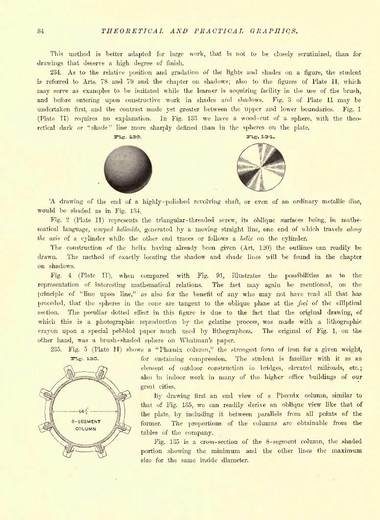
84 THEORETICAL AND PRACTICAL GRAPHIQS.
This method is better adapted for large work, that is not to be closely scrutinized, than for
drawings that deserve a high degree of finish.
234. As to the relative position and gradation of the lights and shades on a figure, the student
is referred to Arts. 78 and 79 and the chapter on shadows; also to the figures of Plate II, which
may serve as examples to be imitated while the learner is acquiring facility in the use of the brush,
and before entering upon constructive work in shades and shadows. Fig. 3 of Plate II may be
undertaken first, and the contrast made yet greater between the upper and lower boundaries. Fig. 1
(Plate II) requires no explanation. In Fig. 133 we have a wood -cut of a sphere, with the theo-
retical dark or "shade" line more sharply defined than in the spheres on the plate.
-. 133. ng. 3-4.
'A drawing of the end of a highly -polished revolving shaft, or even of an ordinary metallic disc,
would be shaded as in Fig. 134.
Fig. 2 (Plate II) represents the triangular -threaded screw, its oblique surfaces being, in mathe-
matical language, warped helicoids, generated by a moving straight line, one end of which travels along
the axis of a cylinder while the other end traces or follows a helix on the cylinder.
The construction of the helix having already been given (Art. 120) the outlines can readily be
drawn. The method of exactly locating the shadow and shade lines will be found in the chapter
on shadows.
Fig. 4 (Plate II), when compared with Fig. 91, illustrates the possibilities as to the
representation of interesting mathematical relations. The fact may again be mentioned, on the
principle of "line upon line," as also for the benefit of any who may not have read all that has
preceded, that the spheres in the cone are tangent to the oblique plane at the foci of the elliptical
section. The peculiar dotted effect in this figure is due to the fact that the original drawing, of
which this is a photographic reproduction by the gelatine process, was made with a lithographic
crayon upon a special pebbled paper much used by lithographers. The original of Fig. 1, on the
other hand, was a brush -shaded sphere on Whatman's paper.
235. Fig. 5 (Plate II) shows a "Phoenix column," the strongest form of iron for a given weight,
for sustaining compression. The student is familiar with it as an
element of outdoor construction in bridges, elevated railroads, etc.;
also in indoor work in many of the higher office buildings of our
great cities.
By drawing first an end view of a Phoenix column, similar to
that of Fig. 135, we can readily derive an oblique view like that of
the plate, by including it between parallels from all points of the
former. The proportions of the columns are obtainable from the
tables of the company.
Fig. 135 is a cross-section of the 8-segment column, the shaded
portion showing the minimum and the other lines the maximum
size for the same inside diameter.
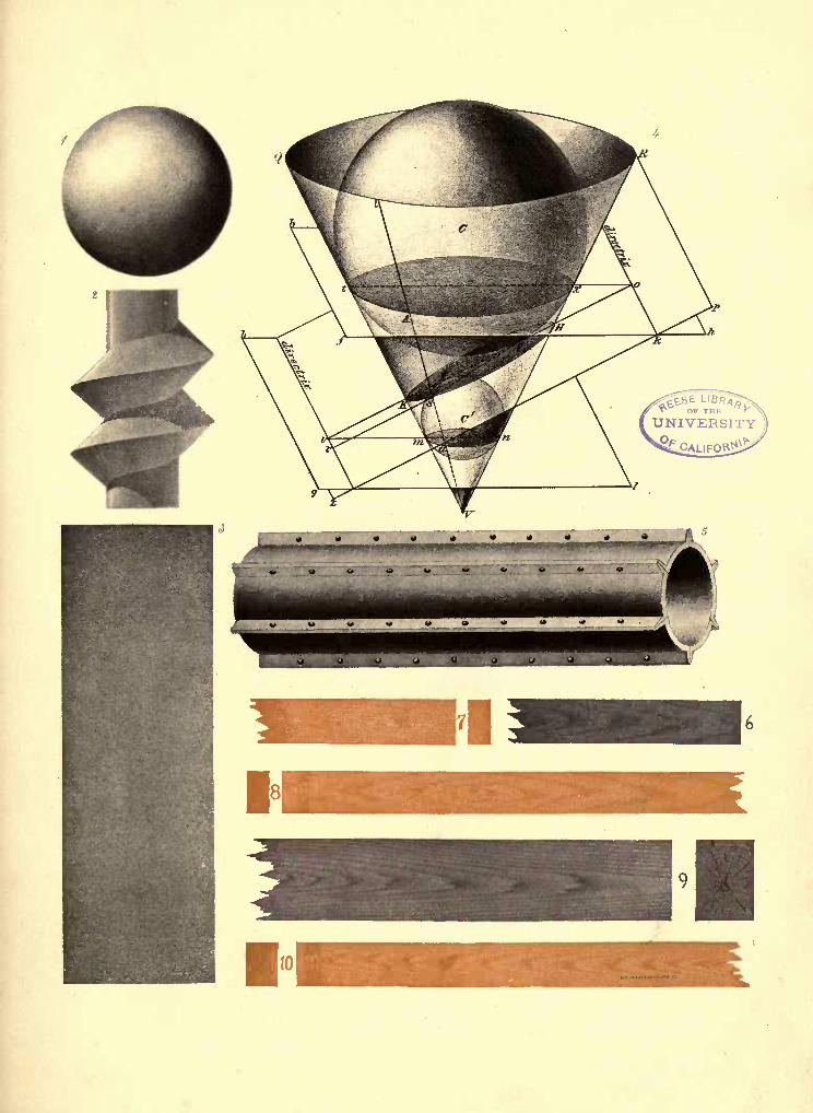
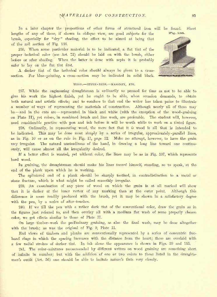
^fATERIALS OF CONSTRUCTION. 85
i
In a later chapter the proportions of other forms of structural iron will be found. Short
lengths of any of these, if shown in oblique view, are good subjects for the **e- ass-
brush, especially for "dry" shading, the effect to be aimed at being that
of the rail section of Fig. 136.
236. When some particular material is to be indicated, a flat tint of the
proper technical color (see Art. 73) should be laid on with the brush, either
before or after shading. When the latter is done with sepia it is probably
safer to lay on the flat tint first.
A darker tint of the technical color should always be given to a cross-
section. For blue -printing, a cross -section may be indicated in solid black.
WOOD. RIVER - BEDS. MASONRY, ETC.
237. While the engineering draughtsman is ordinarily so pressed for time as not to be able to
give his work the highest finish, yet he ought to be able, when occasion demands, to obtain
both natural and artistic effects; and to conduce to that end the writer has taken pains to illustrate
a number of ways of representing the materials of construction. Although nearly all of them maybe and in the cuts are represented in black and white (with the exception of the wood -graining
on Plate II), yet colors, in combined brush and line work, are preferable. The student will, however,
need considerable practice with pen and ink before it will be worth while to work on a tinted figure.
238. Ordinarily, in representing wood, the mere fact that it is wood is all that is intended to
be indicated. This may be done most simply by a series of irregular, approximately -parallel lines,
as in Fig. 10 or as on the rule in Fig. 17, page 12. Make no attempt, however, to have the grain
very irregular. The natural unsteadiness of the hand, in drawing a long line toward one continu-
ously, will cause almost all the irregularity desired.
If a better effect is wanted, yet without color, the lines may be as in Fig. 107, which represents
hard wood.
In graining, the draughtsman should make his lines toward himself, standing, so to speak, at the
end of the plank upon which he is working.
The splintered end of a plank should be sharply toothed, in contradistinction to a metal or
stone fracture, which is what might be called smoothly irregular.
239. An examination of any piece of wood on which the grain is at all marked will show
that it is darker at the inner vertex of any marking than at the outer point. Although this
difference is more readily produced with the brush, yet it may be shown in a satisfactory degree
with the pen, by a series of after -touches.
240. If we fill the pen with a rather dark tint of the conventional color, draw the grain as in
the figures just referred to, and then overlay all with a medium flat wash of some properly chosen
color, we get effects similar to those of Plate II.
On large timber-work the preliminary graining, as also the final wash, may be done altogether
with the brush; as was the original of Fig. 9, Plate II.
End views of timbers and planks are conventionally represented by a series of concentric free-
hand rings in which the spacing increases with the distance from the heart; these are overlaid with
a few radial strokes of darker tint. In ink aione the appearance is shown in Figs. 39 and 115.
241. The color -mixtures recommended by different writers on wood graining are something short
of infinite in number; but with the addition of one or two colors to those listed in the draughts-
man's outfit (Art. 56) one should be able to imitate nature's tints very closely.
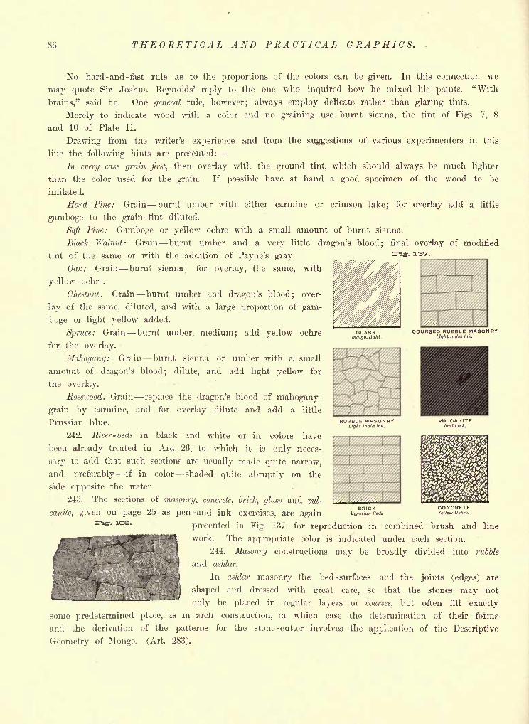
86 THEORETICAL AND PRACTICAL GRAPHICS.
. 137-.
No hard-and-fast rule as to the proportions of the colors can be given. In this connection we
may quote Sir Joshua Reynolds' reply to the one who inquired how he mixed his paints. "With
brains," said he. One general rule, however; always employ delicate rather than glaring tints.
Merely to indicate wood with a color and no graining use burnt sienna, the tint of Figs 7, 8
and 10 of Plate II.
Drawing from the writer's experience and from the suggestions of various experimenters in this
line the following hints are presented:
In every case grain first, then overlay with the ground tint, which should always be much lighter
than the color used for the grain. If possible have at hand a good specimen of the wood to be
imitated.
Hard Pine: Grain burnt umber with either carmine or crimson lake; for overlay add a little
gamboge to the grain -tint diluted.
Soft Pine: Gamboge or yellow ochre with a small amount of burnt sienna.
Black Walnut: Grain burnt umber and a very little dragon's blood; final overlay of modified
tint of the same or with the addition of Payne's gray.
Oak: Grain burnt sienna; for overlay, the same, with
yellow ochre.
Chestnut: Grain burnt umber and dragon's blood; over-
lay of the same, diluted, and with a large proportion of gam-
boge or light yellow added.
Spruce: Grain burnt umber, medium; add yellow ochre
for the overlay.
Mahogany: Grain burnt sienna or umber with a small
amount of dragon's blood; dilute, and add light yellow for
the overlay.
Rosewood: Grain replace the dragon's blood of mahogany-
grain by carmine, and for overlay dilute and add a little
Prussian blue.
242. River-beds in black and white or in colors have
been already treated in Art. 26, to which it is only neces-
sary to add that such sections are usually made quite narrow,
and, preferably if in color shaded quite abruptly on the
side opposite the water.
243. The sections of masonry, concrete, brick, glass and vul-
canite, given on page 25 as pen and ink exercises, are again
presented in Fig. 137, for reproduction in combined brush and line
work. The appropriate color is indicated under each section.
244. Masonry constructions may be broadly divided into rubble
and ashlar.
In ashlar masonry the bed -surfaces and the joints (edges) are
shaped and dressed with great care, so that the stones may not
only be placed in regular layers or courses, but often fill exactly
some predetermined place, as in arch construction, in which case the determination of their forms
and the derivation of the patterns for the stone-cutter involves the application of the Descriptive
Geometry of Monge. (Art. 283).
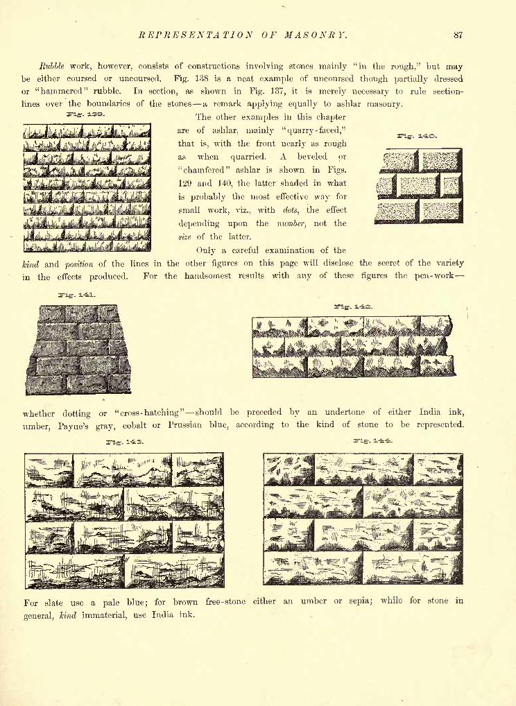
REPRESENTATION OF MASONRY. 87
Fig. 1-40.
Rubble work, however, consists of constructions involving stones mainly "in the rough," but maybe either coursed or uncoursed. Fig. 138 is a neat example of uncoursed though partially dressed
or "hammered" rubble. In section, as shown in Fig. 137, it is merely necessary to rule section-
lines over the boundaries of the stones a remark applying equally to ashlar masonry.
The other examples in this chapter
are of ashlar, mainly"quarry -
faced,"
that is, with the front nearly as rough
as when quarried. A beveled or
"chamfered" ashlar is shown in Figs.
129 and 140, the latter shaded in what
is probably the most effective way for
small work, viz., with dots, the effect
depending upon the number, not the
size of the latter.
Only a careful examination of the
kind and position of the lines in the other figures on this page will disclose the secret of the variety
in the effects produced. For the handsomest results with any of these figures the pen-work
whether dotting or "cross-hatching" should be preceded by an undertone of either India ink,
umber, Payne's gray, cobalt or Prussian blue, according to the kind of stone to be represented.
. 143.
For slate use a pale blue; for brown free -stone either an umber or sepia; while for stone in
general, kind immaterial, use India ink.
88 THEORETICAL AND PRACTICAL GRAPHICS.
CHAPTER VII.
FREE-HAND AND MECHANICAL LETTERING. PROPORTIONING OF TITLES.
245. Practice in lettering forms an essential part of the elementary work of a draughtsman.
Every drawing has to have its title, and the general effect of the result as a whole depends largely
upon the quality of the lettering.
Other things being equal, the expert and rapid draughtsman in this line has a great advantage
over one who can do it but slowly. For this reason free-hand lettering is at a high premium, and
the beginner should, therefore, aim not only to have his letters correctly formed and properly spaced,
but, as far as possible, to do without mechanical aids in their construction. When under great
pressure as to time it is, however, perfectly legitimate to employ some of the mechanical expedients
used in large establishments as "short cuts" and labor-savers. Among these the principal are
"tracing
" and the use of rubber types.
246. To trace a title one must have at hand complete printed alphabets of the size of type required.
Placing a piece of tracing-paper over the letter wanted, it is traced with a hard pencil, the paper
then slipped along to the next letter needed, and the process repeated until the words desired have
been outlined. The title is then transferred to the drawing by first running over the lines on the
back of the tracing-paper with a soft pencil, after which it is only necessary to re-trace the letters
with a hard pencil, on the face of the transfer -paper, to find their outlines faintly yet sufficiently
indicated on the paper underneath. Carbon paper may also be used for transferring.
247. The process just described would be of little service to a ready free-hand draughtsman,
but with the use of rubber types, for the words most frequently recurring in the titles, a merely
average worker may easily get results which in point of time cannot be exceeded by any other
method. When employing such types either of the following ways may be adopted : (a) a light
impression may be made with the aniline ink ordinarily used on the pads, and the outlines then
followed and the "filling in" done either with a writing- pen* or fine- pointed sable -hair brush; or
(b) the impression may be made after moistening the types on a pad that has been thoroughly wet
with a light tint of "India ink. The drawing-ink must then be immediately applied, free-hand,
with a Falcon pen or sable brush, before the type -impression can dry. The pen need only be passed
down the middle of a line, as on the dampened surface the ink will spread instantly to the outlines.
248. The educated draughtsman should, however, be able not only to draw a legible title of the
simple character required for shop -work, and in which the foregoing expedients would be mainly
serviceable, but be prepared also for work out of the ordinary line, and, if need be, quite elaborate,
as on a competitive drawing. Such knowledge can only be gained by careful observation of the
forms of letters, and considerable practice in their construction.
No rigid rules can be laid down as to choice of alphabets for the various possible cases.
Common -sense, custom and a natural regard for the "fitness of things" are the determining factors.
Obviously rustic letters would be out of place on a geometrical drawing, and other incongruities
1 Ket'er to Art. 27 with regard to the pens to be used for the various styles of letters.
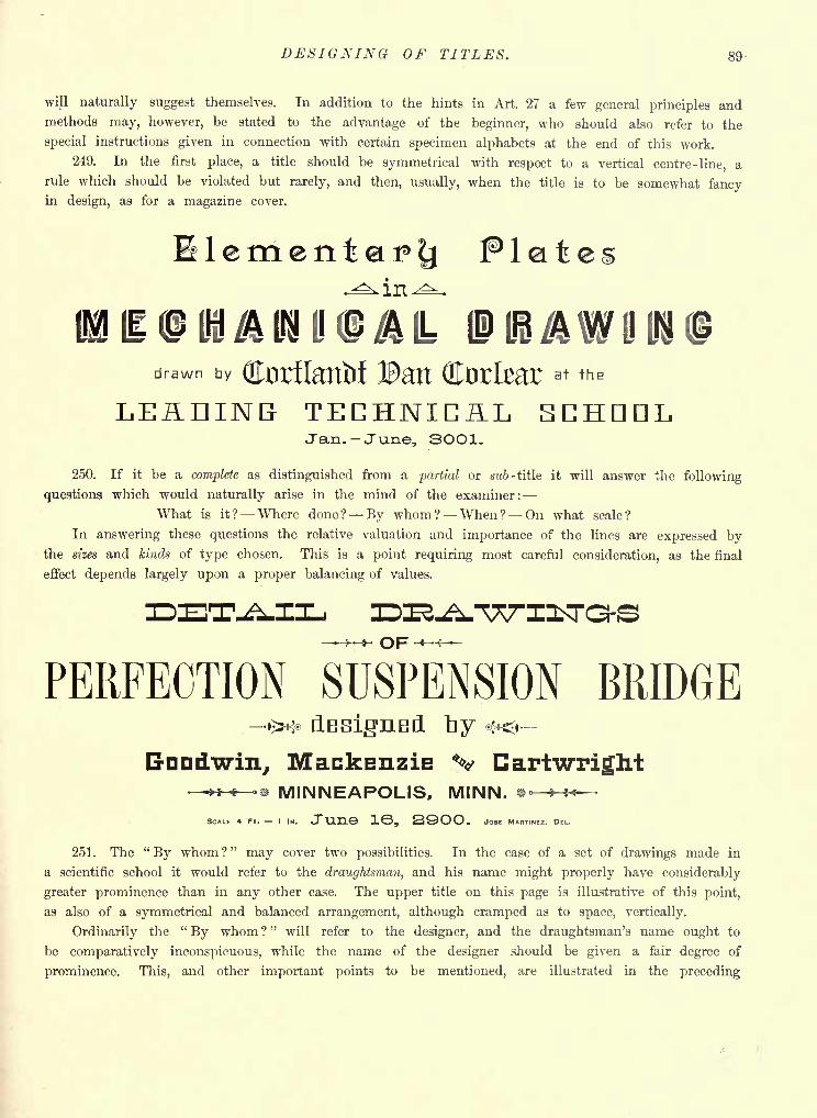
DESIGNING OF TITLES. 89-
will naturally suggest themselves. In addition to the hints in Art. 27 a few general principles andmethods may, however, be stated to the advantage of the beginner, who should also refer to the
special instructions given in connection with certain specimen alphabets at the end of this work.
249. In the first place, a title should be symmetrical with respect to a vertical centre-line, a
rule which should be violated but rarely, and then, usually, when the title is to be somewhat fancyin design, as for a magazine cover.
Plates
BOlAIIIOAt DRAWINGdrawn by Qlorflatttif Ban dtofear ^ ^
LEADING TECHNICAL SCHOOLJan. June, 3OO1.
250. If it be a complete as distinguished from a partial or sub- title it will answer the following
questions which would naturally arise in the mind of the examiner:
What is it? Where done? By whom ? When ? On what scale?
In answering these questions the relative valuation and importance of the lines are expressed bythe sizes and kinds of type chosen. This is a point requiring most careful consideration, as the final
effect depends largely upon a proper balancing of values.
OF
PERFECTION SUSPENSION BRIDGE>* dasigned,
Dnndwin, Mackenzie %> Cartwright- > < -e MINNEAPOLIS, MINN. K.
SCALE 4 FT. = I IN. JtinS 1, 2OO. JOSE MARTINEZ. DEL.
251. The "By whom?" may cover two possibilities. In the case of a set of drawings made in
a scientific school it would refer to the draughtsman, and his name might properly have considerably
greater prominence than in any other case. The upper title on this page is illustrative of this point,
as also of a symmetrical and balanced arrangement, although cramped as to space, vertically.
Ordinarily the "By whom ?
"will refer to the designer, and the draughtsman's name ought to
be comparatively inconspicuous, while the name of the designer should be given a fair degree of
prominence. This, and other important points to be mentioned, are illustrated in the preceding
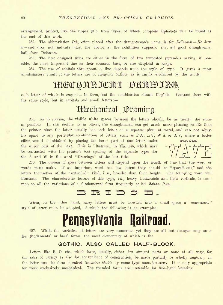
90 THEORETICAL AND PRACTICAL GRAPHICS.
arrangement, printed, like the upper title, from types of which complete alphabets will be found at
the end of this work.
252. The abbreviation Del., often placed after the draughtsman's name, is for Delineavit He drew
it and does not indicate what the visitor at the exhibition supposed, that all good draughtsmen
hail from Delaware.
253. The best designed titles are either in the form of two truncated pyramids having, if pos-
sible, the most important line as their common base, or else elliptical in shape.
254. The use of capitals throughout a line depends upon the style of type. It gives a most
unsatisfactory result if the letters are of irregular outline, as is amply evidenced by the words
each letter of which is exquisite in form, but the combination almost illegible. Contrast them with
the same style, but in capitals and small letters:
Utefjatttcal255. As to spacing, the visible white spaces between the letters should be as nearly the same
as possible. In this feature, as in others, the draughtsman can get much more pleasing results than
the printer, since the latter usually has each letter on a separate piece of metal, and can not adjust
his space to any particular combination of letters, such as FA, L V, W A or A V, where a better
effect would be obtained by placing the lower part of one letter under
the upper part of the next. This is illustrated in Fig. 146, which may "v'V"be contrasted with the printer's best spacing of the separate types for
/ / \ * / Ht,hf> A and W in thfi word " Drawings " nf thfi last, titlfi -/ -/ -I J Jthe A and W in the word "
Drawings" of the last title.
256. The amount of space between letters will depend upon the length of line that the word or
words must make. If an important word has few letters they should be "spaced out," and the
letters themselves of the" extended "
kind, i. e., broader than their height. The following word will
illustrate. The characteristic feature of this type, viz., heavy horizontals and light verticals, is com-
mon to all the variations of a fundamental form frequently called Italian Print.
When, on the other hand, many letters must be crowded into a small space, a " condensed "
style of letter must be adopted, of which the following is an example:
Pennsylvania Railroad.257. While the varieties of letters are very numerous yet they are all but changes rung on a
few fundamental or basal forms, the most elementary of which is the
GOTHIC, ALSO CALLED HALF- BLOCK.Letters like B, 0, etc., which have, usually, either few straight parts or none at all, may, for
the sake of variety as also for convenience of construction, be made partially or wholly angular; in
the latter case the form is called Geometric Gothic by some type manufacturers. It is only appropriate
for work exclusively mechanical. The rounded forms are preferable for free-hand lettering.

LETTERING. 91
The following complete Gothic alphabet is so constructed that whether designed in its
densed" or "extended" form the proper proportions may be easily preserved.
con-
* IM
f V 1 \ U i.
Taking all the solid parts of the letters at the same width as the I, we will find any letter of
average width, as U, to be twice that unit, plus the opening between the uprights, which last, being
indeterminate, we may call x, making it small for a "condensed" letter, and broad as need be for
an "extended" form.
The word march would foot up 5 U + 3, disregarding- as we would invariably the amount the
foot of the R projects beyond the main right-hand outline of the letter. In terms of x this makes
5 x + 13, as U= x + 2. Allowing spaces of 1| unit width between letters adds 5 to the above, making5 x 4- 18 for the total length in terms of the I. Assuming x equal to twice the unit we would
have the whole word equal to twenty -eight units; and if it were to extend seven inches the width
of the solid parts would therefore be one -quarter of an inch.
Where the width of a letter is not indicated it is assumed to be that of the U. The W is
equal to 2U 1. This relation, however, does not hold good in all alphabets.
The angular corners are drawn usually with the 45 triangle.
The guide-lines show what points of the various letters are to be found on the same level, and
should be but faintly pencilled.
As remarked in Art. 27, the extended form of Gothic is one of the best for dimensioning and
lettering working drawings, and is rapidly coming into use by the profession.
258. The Full -Block letter next illustrated is easier to work with than the Gothic in the matter of
preliminary estimate, as the width of each letter in terms of unit squares is evident at a glance.
The same word march would foot up twenty -seven squares without allowing for spaces between
letters. Calling the latter each two we would have thirty -five squares for the same length as before
(seven inches), making one -fifth of an inch for the width of the solid parts. For convenience the
widths of the various letters are summarized:
1 = 3; C,G,O,Q,S,Z= 4; A, B, D,E,F, J, L, P, R,T,&= 5; H,K,N,U, V,X, Y= 6; M= 7; W= 8.
259. In case the preliminary figuring were only approximate and there were but two words in
the line, as, for example, Mechanical Drawing, a safe method of working would be to make a fair
allowance for the space between the words, begin the first word at the calculated distance to the
left of the vertical centre-line, complete it, then work the second word backward, beginning with the
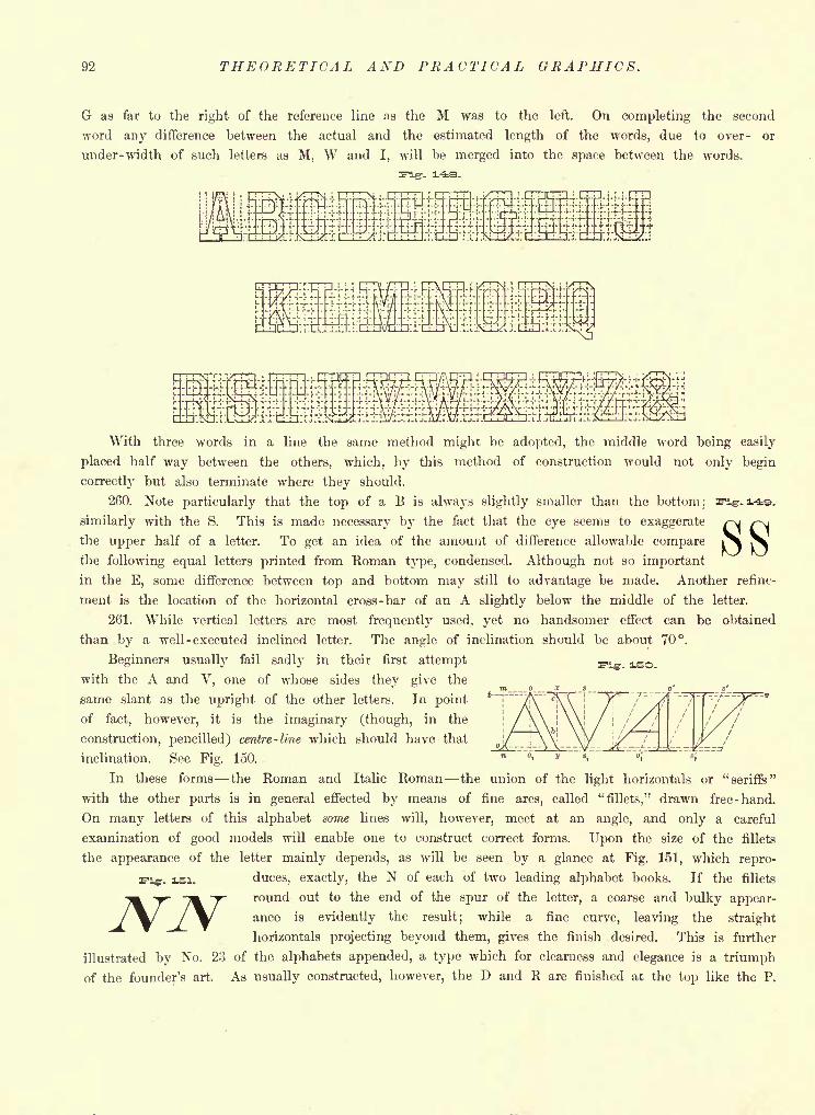
92 THEORETICAL AND PRACTICAL GRAPHICS.
G as far to the right of the reference line as the M was to the left. On completing the second
word any difference between the actual and the estimated length of the words, due to over- or
under- width of such letters as M, W and I, will be merged into the space between the words.
H-Y-KrvI- vi^rsH-i-i-:--- '-<' !-
fT+^H'-rrtH-F'-iv-F--'--^
With three words in a line the same method might be adopted, the middle word being easily
placed half way between the others, which, by this method of construction would not only begin
correctly but also terminate where they should.
260. Note particularly that the top of a B is always slightly smaller than the bottom;
similarly with the S. This is made necessary by the fact that the eye seems to exaggerate
the upper half of a letter. To get an idea of the amount of difference allowable comparethe foUowing equal letters printed from Roman type, condensed. Although not so important
in the E, some difference between top and bottom may still to advantage be made. Another refine-
ment is the location of the horizontal cross-bar of an A slightly below the middle of the letter.
261. While vertical letters are most frequently used, yet no handsomer effect can be obtained
than by a well - executed inclined letter. The angle of inclination should be about 70.
Beginners usually fail sadly in their first attempt
with the A and V, one of whose sides they give the
same slant as the upright of the other letters. In point
of fact, however, it is the imaginary (though, in the
construction, pencilled) centre-line which should have that
inclination. See Fig. 150.
In these forms the Roman and Italic Roman the union of the light horizontals or "seriffs"
with the other parts is in general effected by means of fine arcs, called "fillets," drawn free-hand.
On many letters of this alphabet some lines will, however, meet at an angle, and only a careful
examination of good models will enable one to construct correct forms. Upon the size of the fillets
the appearance of the letter mainly depends, as will be seen by a glance at Fig. 151, which repro-
duces, exactly, the N of each of two leading alphabet books. If the fillets
round out to the end of the spur of the letter, a coarse and bulky appear-
ance is evidently the result; while a fine curve, leaving the straight
horizontals projecting beyond them, gives the finish desired. This is further
illustrated by No. 23 of the alphabets appended, a type which for clearness and elegance is a triumph
of the founder's art. As usually constructed, however, the D and R are finished at the top like the P.
-. isi.
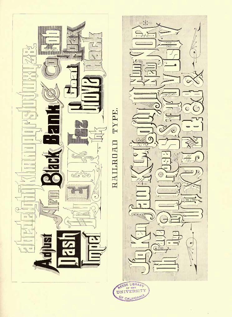
i3Hl^.fe}
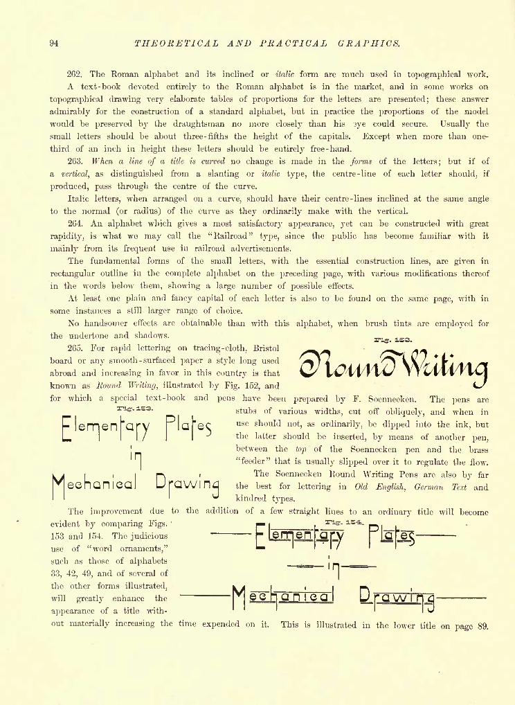
94 THEORETICAL AND PRACTICAL GRAPHICS.
262. The Roman alphabet and its inclined or italic form are much used in topographical work.
A text-book devoted entirely to the Roman alphabet is in the market, and in some works on
topographical drawing very elaborate tables of proportions for the letters are presented; these answer
admirably for the construction of a standard alphabet, but in practice the proportions of the model
would be preserved by the draughtsman no more closely than his ?ye could secure. Usually the
small letters should be about three- fifths the height of the capitals. Except when more than one-
third of an inch in height these letters should be entirely free-hand.
263. When a line of a title is curved no change is made in the forms of the letters; but if of
a vertical, as distinguished from a slanting or italic type, the centre-line of each letter should, if
produced, pass through the centre of the curve.
Italic letters, when arranged on a curve, should have their centre-lines inclined at the same angle
to the normal (or radius) of the curve as they ordinarily make with the vertical.
264. An alphabet which gives a most satisfactory appearance, yet can be constructed with great
rapidity, is what we may call the "Railroad" type, since the public has become familiar with it
mainly from its frequent use in railroad advertisements.
The fundamental forms of the small letters, with the essential construction lines, are given in
rectangular outline in the complete alphabet on the preceding page, with various modifications thereof
in the words below them, showing a large number of possible effects.
At least one plain and fancy capital of each letter is also to be found on the same page, with in
some instances a still larger range of choice.
No handsomer effects are obtainable than with this alphabet, when brush tints are employed for
the undertone and shadows.
265. For rapid lettering on tracing -cloth, Bristol
board or any smooth -surfaced paper a style long used
abroad and increasing in favor in this country is that
known as Round Writing, illustrated by Fig. 152, and
for which a special text-book and pens have been prepared by F. Soennecken. The pens are
stubs of various widths, cut off obliquely, and when in
use should not, as ordinarily, be dipped into the ink, but
the latter should be inserted, by means of another pen,
between the top of the Soennecken pen and the brass
"feeder" that is usually slipped over it to regulate the flow.
The Soennecken Round Writing Pens are also by far
the best for lettering in Old English, German Text and
kindred types.
The improvement due to the addition of a few straight lines to an ordinary title will become
evident by comparing Figs.'
153 and 154. The judicious
use of "word ornaments,"
such as those of alphabets
33, 42, 49, and of several of
the other forms illustrated,
,h<eehaniea
Meerran lwill greatly enhance the|
& CI"]Q H I Q Q
appearance of a title with-
out materially increasing the time expended on it. This is illustrated in the lower title on page 89.
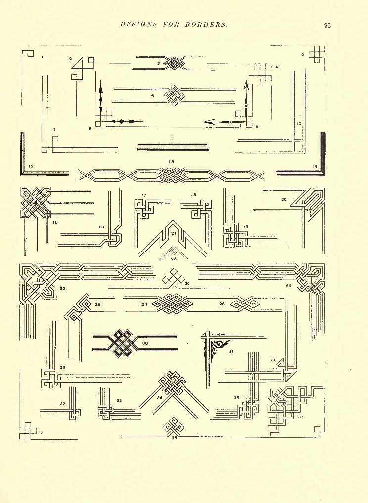
DESIGNS FOR BORDERS. 95
96 THEORETICAL AND PRACTICAL GRAPHICS.
266. Borders. Another effective adjunct to a map or other drawing is a neat border. It should
be strictly in keeping with the drawing, both as to character and simplicity.
On page 95 a large number of corner designs and borders is presented, one-third of them orig-
inal designs, by the writer, for this work. The principle of their construction is illustrated by Fig.
155, in which the larger design shows the necessary preliminary lines, and the smaller the complete
corner. It is evident in this, as in all cases of interlaced designs, that we must first lay off each
way from the corner as many equal distances as there are bands and spaces, and lightly make a
network of squares or of rhombi, if the angles are acute by pencilled construction -lines through
the points of division.
267. Shade lines on borders. The usual rule as to shade lines applies equally to these designs,
thus: Following any band or pair of lines making the turns as one
piece, if it runs horizontally the lower line is the heavier, while in a
vertical pair the right-hand line is the shaded line. This is on the
assumption that the light is coming in the direction usually assumed for
mechanical drawings, i. e., descending diagonally from left to right.
In case a pair of lines runs obliquely, the shaded lines may be
determined by a study of their location on the designs of the plate of
borders.
It need hardly be said that on any drawing and its title the light
should be supposed to come from but one 'direction throughout, and not be
shifted; and the shaded lines should be located accordingly. This rule is always imperative.
In drawing for scientific illustration or in art work it is allowable to depart from the usual
strictly conventional direction of light, if a better effect can thereby be secured.
268. A striking letter can be made by drawing the shade line only, as in Fig. 146, page 90, which
we may call "Full -Block Shade -Line," being based upon the alphabet of Fig. 148, page 92, as to
construction. Owing to its having more projecting parts it gives a much handsomer effect than the
The student will notice that the light comes from different directions in the two examples.
These forms are to the ordinary fully -outlined letters what art work of the "impressionist"
school is to the extremely detailed and painstaking work of many; what is actually seen suggests
an equal amount not on the paper or canvas.
269. While a teacher of draughting may well have on hand, as reference works for his class,
such books on lettering as Prang's, Becker's and others equally elaborate, yet they will be found of
only occasional service, their designs being as a rule more highly ornate than any but the specialist
would dare undertake, and mainly of a character unsuitable for the usual work of the engineering or
architectural draughtsman, whose needs were especially in mind when selecting types for this work.
The alphabets appended afford a large range of choice among the handsomest forms recently
designed by the leading type manufacturers, also containing the best among former types; and with
the "Railroad," Full -Block and Half- Block alphabets of this chapter, proportioned and drawn by the
writer, supply the student with a practical "stock in trade" that it is believed will require but
little, if any, supplementing.
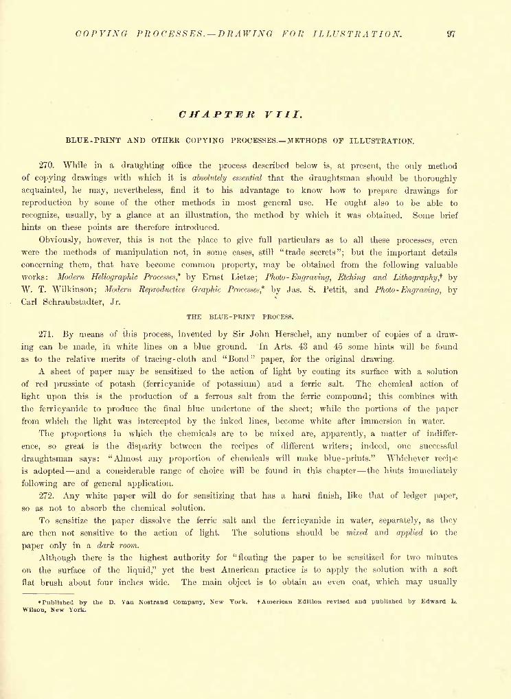
COPYING PROCESSES. DRAWING FOR ILLUSTRATION. 97
CHAPTER VIII.
BLUE -FEINT AND OTHER COPYING PROCESSES. METHODS OF ILLUSTRATION.
270. While in a draughting office the process described below is, at present, the only method
of copying drawings with which it is absolutely essential that the draughtsman should be thoroughly
acquainted, he may, nevertheless, find it to his advantage to know how to prepare drawings for
reproduction by some of the other methods in most general use. He ought also to be able to
recognize, usually, by a glance at an illustration, the method by which it was obtained. Some brief
hints on these points are therefore introduced.
Obviously, however, this is not the place to give full particulars as to all these processes, even
were the methods of manipulation not, in some cases, still "trade secrets"; but the important details
concerning them, that have become common property, may be obtained from the following valuable
works: Modern Heliographic Processes* by Ernst Lietze; Photo -Engraving, Etching and Lithography ,t byW. T. Wilkinson; Modern Reproductive Graphic Processes," by Jas. S. Pettit, and Photo -Engraving, byCarl Schraubstadter, Jr.
THE BLUE -PRINT PROCESS.
271. By means of this process, invented by Sir John Herschel, any number of copies of a draw-
ing can be made, in white lines on a blue ground. In Arts. 43 and 45 some hints will be found
as to the relative merits of tracing -cloth and "Bond" paper, for the original drawing.
A sheet of paper may be sensitized to the action of light by coating its surface with a solution
of red prussiate of potash (ferri cyanide of potassium) and a ferric salt. The chemical action of
light upon this is the production of a ferrous salt from the ferric compound; this combines with
the ferricyanide to produce the final blue undertone of the sheet; while the portions of the paper
from which the light was intercepted by the inked lines, become white after immersion in water.
The proportions in which the chemicals are to be mixed are, apparently, a matter of indiffer-
ence, so great is the disparity between the recipes of different writers; indeed, one successful
draughtsman says: "Almost any proportion of chemicals will make blue-prints." Whichever recipe
is adopted and a considerable range of choice will be found in this chapter the hints immediately
following are of general application.
272. Any white paper will do for sensitizing that has a hard finish, like that of ledger paper,
so as not to absorb the chemical solution.
To sensitize the paper dissolve the ferric salt and the ferricyanide in water, separately, as they
are then not sensitive to the action of light. The solutions should be mixed and applied to the
paper only in a dark room.
Although there is the highest authority for "floating the paper to be sensitized for two minutes
on the surface of the liquid," yet the best American practice is to apply the solution with a soft
flat brush about four inches wide. The main object is to obtain an even coat, which may usually
Published by the D. Van Nostrand Company, New York. t American Edition revised and published by Edward L.
Wilson, New York.
98 THEORETICAL AND PRACTICAL GRAPHICS.
be secured by a primary coat of horizontal strokes followed by an overlay of vertical strokes; the
second coat applied before the first dries. If necessary, another coat of diagonal strokes may be
given to secure evenness. The thicker the coating given the longer the time required in printing.
A bowl or flat dish or plate will be found convenient for holding the small portion of the solution
required for use at any one time. The chemicals should not get on the back of the sheet.
Each sheet, as coated, should be set in a dark place to dry, either "tacked to a board by two
adjacent corners,'' or "hung on a rack or over a rod," or "placed in a drawer one sheet in a
drawer," varying instructions, illustrating the quite general truth that there are usually several
almost equally good ways of doing a thing.
273. To copy a drawing, place the prepared paper, sensitized side up, on a drawing - board or
printing -frame on which there has been fastened, smoothly, either a felt pad or canton flannel cloth.
The drawing is then immediately placed over the first sheet, inked side up, and contact secured
between the two by a large sheet of plate glass, placed over all.
Exposure in the direct rays of the sun for four or five minutes is usually sufficient. The
progress of the chemical action can be observed by allowing a corner of the paper to project beyond
the glass. It has a grayish hue when sufficiently exposed.
If the sun's rays are not direct, or if the day is cloudy, a proportionately longer time is required,
running up in the latter case, from minutes into hours. Only experiment will show whether one's
solution is "quick" or "slow;" or the time required by the degree of cloudiness.
A solution will print more quickly if the amount of water in it be increased, or if more iron
is used; but in the former case the print will not be as dark, while in the latter the results, as to
whiteness of lines, are not so apt to be satisfactory.
Although fair results can be obtained with paper a month or more after it has been sensitized,
yet they are far more satisfactory if the paper is prepared each time (and dried) just before using.
On taking the print out of the frame it should be immediately immersed and thoroughly
washed in cold water for from three to ten minutes, after which it may be dried in either of the
ways previously suggested.
If many prints are being made, the water should be frequently changed so as not to become
charged with the solution.
274. The entire process, while exceedingly simple in theory, varies, as to its results, with the
experience and judgment of the manipulator. To his choice the decision is left between the follow-
ing standard recipes for preparing the sensitizing solution. The "parts" given are all by weight.
In every case the potash should be pulverized, to facilitate its dissolving.
No. 1. (From Le Genie Civil.)
. Red Prussiate of Potash 8 parts.Solution No.
\
Re
I Wa/ater 70 parts.
f Citrate of Iron and Ammonia 10 parts.N - 2 -
{ Water 70 parts.
Filter the solutions separately, mix equal quantities and then filter again.
No. 2. (From U. S. Laboratory at Willett's Point).
f Double Citrate of Iron and Ammonia 1 ounce.Solution No. 1. \
Water 4 ounces.
Red Prussiate of Potassium 1 ounce.Solution No. 2. \ ...
Water 4 ounces.
tion.-j
BLUE-PRINT PROCESS. 99
No. 3. (Lietze's Method).
5 ounces, avoirdupois, Red Prussiate of Potash.Stock Solution. -I
32 fluid ounces Water.
"After the red prussiate of potash has been dissolved which requires from one to two daysthe liquid is filtered. This solution remains in good condition for a long time. Whenever it is
required to sensitize paper, dissolve, for every two hundred and forty square feet of paper,
{1ounce, avoirdupois, Citrate of Iron and Ammonia,
4} fluid ounces Water,
and mix this with an equal volume of the stock solution.
The reason for making a stock solution of the red prussiate of potash is, that it takes a con-
siderable time to dissolve and because it must be filtered. There are many impurities in this
chemical which can be removed by filtering. Without filtering, the solution will not look clear.
The reason for making no stock solution of the ferric citrate of ammonia is that such solution soon
becomes moldy and unfit for use. This ferric salt is brought into the market in a very pure state,
and does not need to be filtered after being dissolved. It dissolves very rapidly. In the solid
form it may be preserved for an unlimited time, if kept in a well -stoppered bottle and protected
against the moisture of the atmosphere. A solution of this salt, or a mixture of it with the solution
of red prussiate of potash, will remain in a serviceable condition for a number of days, but it will
spoil, sooner or later, according to atmospheric conditions. . . . Four ounces of sensitizing solution,
for blue prints, are amply sufficient for coating one hundred square feet of paper, and cost about
six cents."
For copying tracings in blue lines or black on a white ground, one may either employ the
recipes given in Lietze's and Pettit's work, or obtain paper already sensitized, from the leading dealers
in draughtsmen's supplies. The latter course has become quite as economical, also, for the ordinary blue-
print, as the preparing of one's own supply.
For copying a drawing in any desired color the following method, known as Tilhet's, is said to
give good results: "The paper on which the copy is to appear is first dipped in a bath con-
sisting of 30 parts of white soap, 30 parts of alum, 40 parts of English glue, 10 parts of
albumen, 2 parts of glacial acetic acid, 10 parts of alcohol of 60, and 500 parts of water. It is
afterward put into a second bath, which contains 50 parts of burnt umber ground in alcohol,
20 parts of lampblack, 10 parts of English glue, and 10 parts of bichromate of potash in 500 parts
of water. They are now sensitive to light, and must, therefore, be preserved in the dark. In
preparing paper to make the positive print another bath is made just like the first one, except that
lampblack is substituted for the burnt umber. To obtain colored positives the black is replaced by
some red, blue or other pigment.
In making the copy the drawing to be copied is put in a photographic printing frame, and the
negative paper laid on it, and then exposed in the usual manner. In clear weather an illumination
of two minutes will suffice. After the exposure the negative is put in water to develop it, and the
drawing will appear in white on a dark ground; in other words, it is a negative or reversed picture-
The paper is then dried and a positive made from it by placing it on the glass of a printing-
frame, and laying the positive paper upon it and exposing as before. After placing the frame in
the sun for two minutes the positive is taken out and put in water. The black dissolves off without
the necessity of moving back and forth."
100 THEORETICAL AND PRACTICAL GRAPHICS.
PHOTO-AND OTHER PROCESSES.
275. If a drawing is to be reproduced on a different scale from that of the original, some one
of the processes which admits of the use of the camera is usually employed. Those of most
importance to the draughtsman are (1) wood engraving; (2) the "wax process" or cerography; (3)
lithography, and (4) the various methods in which the photographic negative is made on a film of
gelatine which is then used directly to print from, or indirectly in obtaining a metal plate from
which the impressions are taken.
In the first three named above the use of the camera is not invariably an element of the
process.
All under the fourth head are essentially photo -processes and their already large number is
constantly increasing. Among them may be mentioned photogravure, collotype, phototype, autotype, photo-
glyph, albertype, heliotype, and heliogravure.
WOOD ENGRAVING.
276. There is probably no process that surpasses the best work of skilled engravers on wood.
This statement will be sustained by a glance at Figs. 14, 15, 20-24, 134, 136, and those illustrating
mathematical surfaces, in the next chapter. Its expensiveness, and the time required to make an
illustration by this method, are its only disadvantages.
Although the camera is often employed to transfer the drawing to the boxwood block in which
the lines are to be cut, yet the original drawing is quite as frequently made in reverse, directly on
the block, by a professional draughtsman who is supposed to have at his disposal either the object
to be drawn or a photograph or drawing thereof. The outlines are pencilled on the block, and the
shades and shadows given in brush tints of India ink, re-enforced, in some cases, by the pencil, for
the deepest shadows.
The "high lights" are brought out by Chinese white. A medium wash of the latter is also
usually spread upon the block as a general preliminary to outlining and shading.
The task of the engraver is to reproduce faithfully the most delicate as well as the strongest
effects obtained on the block with pencil and brush, cutting away all that is not to appear in black
in the print. The finished block may then be used to print from directly, or an electrotype block
can be obtained from it which will stand a large number of impressions much better than the wood.
CEROGRAPHY.
277. For map-making, illustrations of machinery, geometrical diagrams and all work mainly in
straight lines or simple curves, and not involving too delicate gradations, the cerographic or "wax
process" is much employed. For clearness it is scarcely surpassed by steel engraving. Figures 36,
90 and 107 are good specimens of the effects obtainable by this method. The successive steps in
the process are (a) the laying of a thin, even coat of wax over a copper plate; (b) the transfer of
the drawing to the surface of the wax, either by tracing or more generally by photography; (c)
the re -drawing or rather the cutting of these lines in the wax, the stylus removing the latter to the
surface of the copper; (d) the taking of an electrotype from the plate and wax, the deposit of
copper filling in the lines from which the wax was removed.
Although in the preparation of the original drawing the lines may preferably be inked, yet it is
not absolutely necessary, provided a pencil of medium grade be employed.
LITHOGRAPHY. PHOTO-ENGRAVING. 101
Any letters desired on the final plate may be also pencilled in their proper places, as the
engraver makes them on the wax with type.
A surface on which section -lining or cross-hatching is desired may have that fact indicated uponit in writing, the direction and number of lines to the inch being given. Such work is then done
with a ruling machine.
Errors may readily be corrected, as the surface of the wax may be made smooth, for recutting,
by passing a hot iron over it.
LITHOGRAPHY. PHOTO - LITHOGRAPHY. CHROMO - LITHOGRAPHY.
278. For lithographic processes a fine-grained, imported limestone is used. The drawing is made
with a greasy ink known as "lithographic" upon a specially prepared paper, from which it is
transferred under pressure, to the surface of the stone. The un-inked parts of the stone are kept
thoroughly moistened with water, which prevents the printer's ink (owing to the grease which the
latter contains) from adhering to any portion except that from which the impressions are desired.
Photo -lithography is simply lithography, with the camera as an adjunct. The positive might be
made directly upon the surface of the stone by coating the latter with a sensitizing solution; but,
in general, for convenience, a sensitized gelatine film is exposed under the negative, and by subsequent
treatment gives an image in relief which, after inking, can be transferred to the surface of the stone
as in the ordinary process.
Chromo- lithography, or lithography in colors, has been a very expensive process, owing to its
requiring a separate stone for each color. Recent inventions render it probable that it will be much
simplified, and the expense correspondingly reduced. The details of manipulation are closely analogous
to those of ink prints.
When colored plates are wanted, in which delicate gradations shall be indicated, chromo - litho-
graphy may preferably be adopted; although "half-tones," with colored inks, give a scarcely less
pleasing effect, as illustrated by Pigs. 7-10, Plate II. But for simple line-work, in two or more
colors, one may preferably employ either cerography or photo -engraving, each of which has not only
an advantage, as to expense, over any lithographic process, but also this in addition that the
blocks can be used by any printer; whereas lithographing establishments necessarily not only prepare
the stone but also do the printing.
PHOTO - ENGRAVING. PHOTO - ZINCOGRAPHY.
279. In this popular and rapid process a sensitized solution is spread upon a smooth sheet of
zinc, and over this the photographic negative is placed. Where not acted on by the light the coat-
ing remains soluble and is washed away, exposing the metal, which is then further acted on by
acids to give more relief to the remaining portions.
Except as described in Art, 281 this process is only adapted to inked work in lines or dots,
which is reproduced faithfully, to the smallest detail. Among the best photo-engravings in this book
are Figs. 10 and 11, 50, 79 and 80.
280. The following instructions for the preparation of drawings, for reproduction by this process,
are those of the American Society of Mechanical Engineers as to the illustration of papers by its
members, and are, in general, such as all the engraving companies furnish on application.
"All lines, letters and figures must be perfectly black on a white ground. Blue prints are not
available, and red figures and lines will not appear. The smoother the paper, and the blacker the
ink, the better are the results. Tracing -cloth or paper answers very well, but rough paper even
102 THEORETICAL AND PRACTICAL GRAPHICS.
Whatman's gives bad lines. India ink, ground or in solution, should be used; and the best lines
are made on Bristol board, or its equivalent with an enameled surface. Brush work, in tint or
grading, unfits a drawing for immediate use, since only line work can be photographed. Hatching
for sections need not be completed in the originals, as it can be done easily by machine on the
block. If draughtsmen will indicate their sections unmistakably, they will be properly lined, and
tints and shadows will be similarly treated.
The best results may be expected by using an original twice the height and width of the
proposed block. The reduction can be greater, provided care has been taken to have the lines far
enough apart, so as not to mass them together. Lines in the plate may run from 70 to 100 to
the inch, and there should be but half as many in a drawing which is to be reduced one -half;
other reductions will be in like proportion.
Draughtsmen may use photographic prints from the objects if they will go over with a carbon
ink all the lines which they wish reproduced. The photographic color can be bleached away by
flowing a solution of bi- chloride of mercury in alcohol over the print, leaving the pen lines only.
Use half an ounce of the salt to a pint of alcohol.
Finally, lettering and figures are most satisfactorily printed from type. Draughtsmen's best efforts
are usually thus excelled. Such letters and figures had therefore best be left in pencil on the
drawings, so they will not photograph but may serve to show what type should be inserted."
To the above hints should be added a caution as to the use of the rubber. It is likely to
diminish the intensity of lines already made and to affect their sharpness; also to make it more
difficult to draw clear-cut lines wherever it has been used.
It may be remarked with regard to the foregoing instructions that they aim at securing that
uniformity, as to general appearance, which is usually quite an object in illustration. But where the
preservation of the individuality and general characteristics of one's work is of any importance what-
ever, the draughtsman is advised to letter his own drawings and in fact finish them entirely, himself,
with, perhaps, the single exception of section -lining, which may be quickly done by means of Day's
Rapid Shading Mediums or by other technical processes.
281. Half Tones. Photo -zincography may be employed for reproducing delicate gradations of light
and shade, by breaking up the latter when making the photographic negative. The result is called
a half tone, and it is one of the favorite processes for high-grade illustration. Figs. 95 and 130
illustrate the effects it gives. On close inspection a series of fine dots in regular order will be noticed,
or else a net- work, so that no tone exists unbroken, but all have more or less white in them.
The methods of breaking up a tone are very numerous. The first patent dates back to 1852.
The principle is practically the same in all, viz., between the object to be photographed and the
plate on which the negative is to be made there is interposed a "screen" or sheet of thin glass, on
which the desired mesh has been previously photographed.
In the making of the "screen" lies the main difference between the variously-named methods.
In Meissenbach's method, by which Figs. 95 and 130 were made, a photograph is first taken, on the
"screen," of a pane of clear glass in which a system of parallel lines one hundred and fifty to the
inch has been cut with a diamond. The ruled glass is then turned at right angles to its first
position and its lines photographed on the screen over the first set, the times of exposure differing
slightly in the two cases, being generally about as 2 to 3.
This process is well adapted to the reproduction of "wash" or brush -tinted drawings, photo-
graphs, etc. The object to be represented, if small, may preferably be furnished to the engraving
company and they will photograph it direct.
PHOTOGRAPHIC ILLUSTRATIVE PR CE S S E
GELATINE FILM PHOTO- PROCESSES.
282. As stated in Art. 275, in which a few of the above processes are named, a gelatine film
may be employed, either as an adjunct in a method resulting in a metal block, or to print from
directly; in the latter case the prints must be made, on special paper, by the company preparing
the film. In the composition and manipulation of the film lies the main difference between otherwise
closely analogous processes. For any of them the company should be supplied with either the original
object or a good drawing or photographic negative thereof.
Not to unduly prolong this chapter which any sharp distinction between the various methods
would involve, yet to give an idea of the general principles of a gelatine process we may conclude
with the details of the preparation of a heliotype plate, given in the language of the circular of a
leading illustrating company. Figs. 1 5 of Plate II illustrate the effect obtained by it.
"Ordinary cooking gelatine forms the basis of the positive plate, the other ingredients being bichro-
mate of potash and chrome alum. It is a pecularity of gelatine, in its normal condition, that it will
absorb cold water, and swell or expand under its influence, but that it will dissolve in hot water. In the
preparation of the plate, therefore, the three ingredients just named, being combined in suitable propor-
tions, are dissolved in hot water, and the solution is poured upon a level plate of glass or metal, and
left there to dry. When dry it is about as thick as an ordinary sheet of parchment, and is stripped
from the drying -plate, and placed in contact with the previously-prepared negative, and the two
together are exposed to the light. The presence of the bichromate of potash renders the gelatine
sheet sensitive to the action of light; and wherever light reaches it, the plate, which was at first
gelatinous or absorbent of water, becomes leathery or waterproof. In other words, wherever light
reaches the plate, it produces in it a change similar to that which tanning produces upon hides in
converting them into leather. Now it must be understood that the negative is made up of trans-
parent parts and opaque parts; the transparent parts admitting the passage of light through them,
and the opaque parts excluding it. When the gelatine plate and the negative are placed in contact,
they are exposed to light with the negative uppermost, so that the light acts through the translucent
portions, and waterproofs the gelatine underneath them; while the opaque portions of the negative
shield the gelatine underneath them from the light, and consequently those parts of the plate remain
unaltered in character. The result is a thin, flexible sheet of gelatine of which a portion is water-
proofed, and the other portion is absorbent of water, the waterproofed portion being the image which
we wish to reproduce. Now we all know the repulsion which exists between water and any form
of grease. Printer's ink is merely grease united with coloring- matter. It follows, that our gelatine
sheet, having water applied to it, will absorb the water in its unchanged parts; and, if ink is then
rolled over it, the ink will adhere only to the waterproofed or altered parts. This flexible sheet of
gelatine, then, prepared as we have seen, and having had the image impressed upon it, becomes the
heliotype plate, capable of being attached to the bed of an ordinary printing-press, and printed in the
ordinary manner. Of course, such a sheet must have a solid base given to it, which will hold it
firmly on the bed of the press while printing. This is accomplished by uniting it, under water, with
a metallic plate, exhausting the air between the two surfaces, and attaching them by atmospheric
pressure. The plate, with the printing surface of gelatine attached, is then placed on an ordinary
platen printing-press, and inked up with ordinary ink. A mask of paper is used to secure white
margins for the prints; and the impression is then made, and is ready for issue."
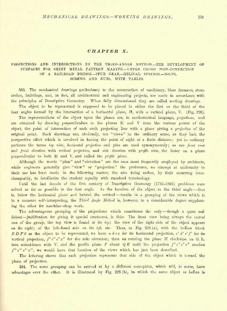
MECHANICAL DRAWINGS. WORKING DRAWINGS. 131
CHAPTER X.
PROJECTIONS AND INTERSECTIONS BY THE THIRD-ANGLE METHOD. THE DEVELOPMENT OPSURFACES FOR SHEET METAL PATTERN MAKING. UPPER CHORD POST-CONNECTION
OF A RAILROAD BRIDGESPUR GEAR. HELICAL SPRINGS. BOLTS,SCREWS AND NUTS, WITH TABLES.
383. The mechanical drawings preliminary to the construction of machinery, blast furnaces, stone
arches, buildings, and, in fact, all architectural and engineering projects, are made in accordance with
the principles of Descriptive Geometry. When fully dimensioned they are called working drawings.
The object to be represented is supposed to be placed in either the first or the third of the
four angles formed by the intersection of a horizontal plane, H, with a vertical plane, V. (Fig. 228).
The representations of the object upon the planes are, in mathematical language, projections, and
are obtained by drawing perpendiculars to the planes H and V from the various points of the
object, the point of intersection of each such projecting line with a plane giving a projection of the
original point. Such drawings are, obviously, not "views" in the ordinary sense, as they lack the
perspective effect which is involved in having the point of sight at a finite distance; yet in ordinary
parlance the terms top view, horizontal projection and plan are used synonymously ;as are front view
and front elevation with vertical projection, and side elevation with profile view, the latter on a plane
perpendicular to both H and V, and called the profile plane.
Although the words "plan" and "elevation
"are the ones most frequently employed by architects,
while engineers generally give "view" or "projection" the preference, no attempt at uniformity in
their use has been made in the following matter, the aim being rather, by their occurring inter-
changeably, to familiarize the student equally with standard terminology.
Until the last decade of the first century of Descriptive Geometry (1795-1895) problems were
solved as far as possible in the first angle. As the location of the object in the third angle that
is, below the horizontal plane and behind the vertical results in a grouping of the views which is
in a measure self- interpreting, the Third Angle Method is, however, to a considerable degree supplant-
ing the other for machine-shop work.
The advantageous grouping of the projections which constitutes the only though a quite suf-
ficient justification for giving it special treatment, is this: The front view being always the central
one of the group, the top view is found at the top; the view of the right side of the object appears
on the right; of the left-hand side on the left, etc. Thus, in Fig. 228 (a), with the hollow block
BDFS as the object to be represented, we have ades for its horizontal projection, c' d' e'f for its
vertical projection, f"e"s"x" for the side elevation; then on rotating the plane H clockwise on G. L.
into coincidence with V, and the profile plane P about QR until the projection /" e" s" x" reaches
f'"e'"s'"x'", we would have that location of the views which has just been described.
The lettering shows that each projection represents that side of the object which is toward the
plane of projection.
384. The same grouping can be arrived at by a different conception, which will, to some, have
advantages over the other. It is illustrated by Fig. 228 (b), in which the same object as before is
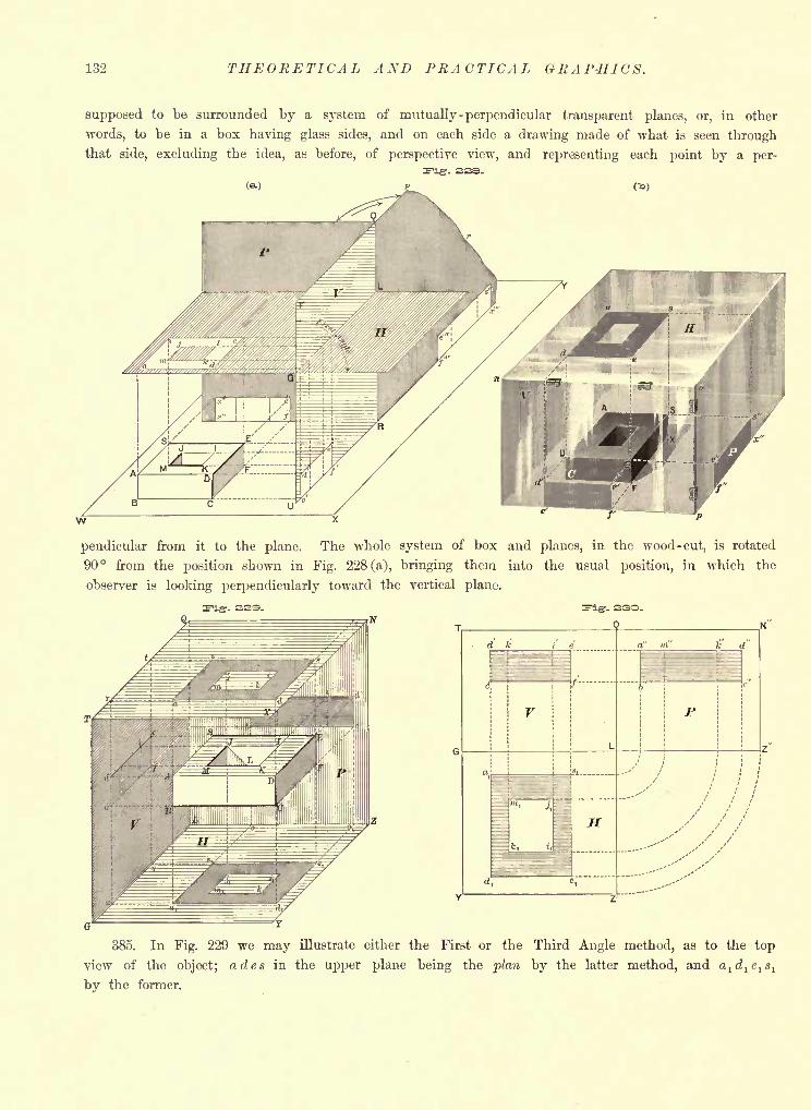
132 THEORETICAL AND PRACTICAL GRAP-HICS.
supposed to be surrounded by a system of mutually -perpendicular transparent planes, or, in other
words, to be in a box having glass sides, and on each side a drawing made of what is seen throughthat side, excluding the idea, as before, of perspective view, and representing each point by a per-
3Figr- see.
pendicular from it to the plane. The whole system of box and planes, in the wood -cut, is rotated
90 from the position shown in Fig. 228 (a), bringing them into the usual position, in which the
observer is looking perpendicularly toward the vertical plane.
385. In Fig. 229 we may illustrate either the First or the Third Angle method, as to the top
view of the object; ades in the upper plane being the plan by the latter method, and a1d
1e
l8
l
by the former.
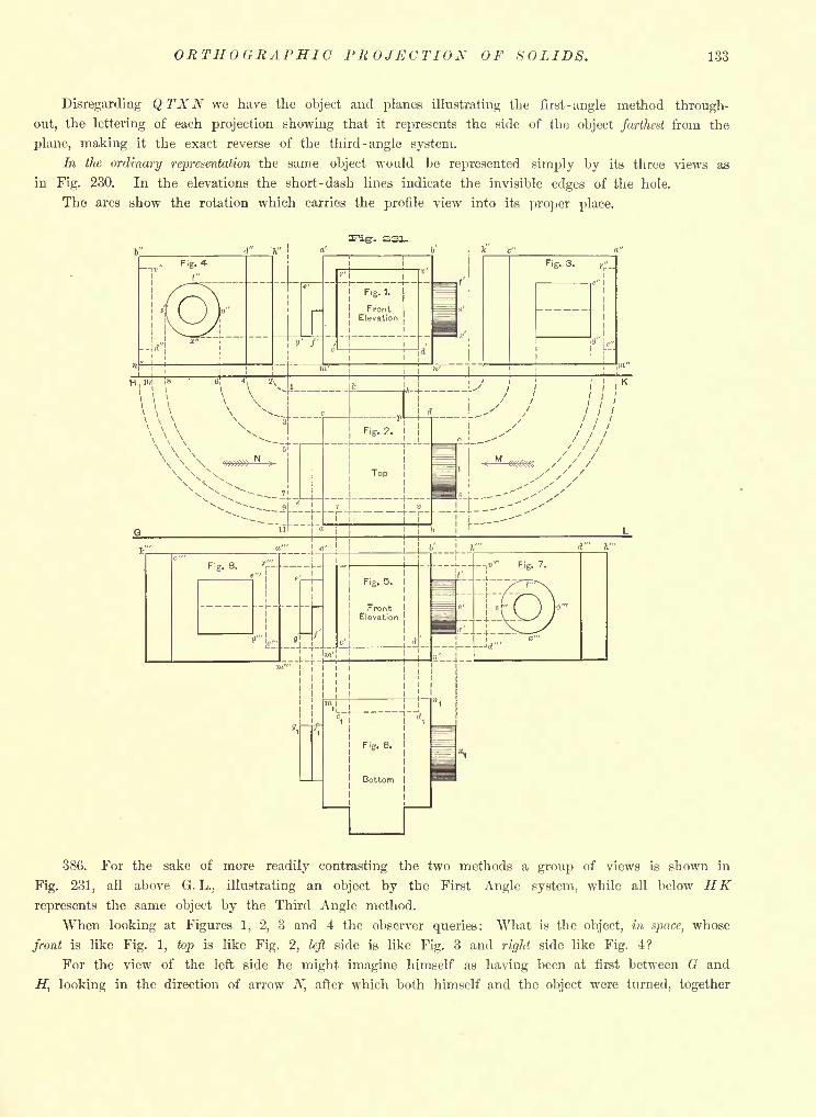
ORTHOGRAPHIC PROJECTION OF SOLIDS. 133
Disregarding Q TXN we have the object and planes illustrating the first -angle method through-
out, the lettering of each projection showing that it represents the side of the object farthest from the
plane, making it the exact reverse of the third -angle system.
In the ordinary representation the same object would be represented simply by its three views as
in Fig. 230. In the elevations the short -dash lines indicate the invisible edges of the hole.
The arcs show the rotation which carries the profile view into its proper place.
-. 231.
386. For the sake of more readily contrasting the two methods a group of views is shown in
Fig. 231, all above G. L., illustrating an object by the First Angle system, while all below HKrepresents the same object by the Third Angle method.
When looking at Figures 1, 2, 3 and 4 the observer queries: What is the object, in space, whose
front is like Fig. 1, top is like Fig. 2, left side is like Fig. 3 and right side like Fig. 4?
For the view of the left side he might imagine himself as having been at first between G and
H, looking in the direction of arrow N, after which both himself and the object were turned, together
134 THEORETICAL AND PRACTICAL GRAPHICS.
to the right, through a ninety- degree arc, when the same side would be presented to his view
in Fig. 3. Similarly, looking in the direction of the arrow M, an equal rotation to the left, as
indicated by the arcs 1-2, 3-4, 5-6, etc., would give in Fig. 4 the view obtained from direction
M. His mental queries would then be answered about as follows: Evidently a cubical block with
a rectangular recess r'v'd'c' in front; on the rear a prismatic projection, of thickness ph and
whose height equals that of the cube; a short cylindrical ring projecting from the right face of the
cube; an angular projecting piece on the left face.
In Fig. 2 the line rv is in short dashes, as in that view the back plane of the recess r'v'd'c'
would be invisible. In Fig. 4 the back plane of the same recess is given the letters, v"d", of the
edge nearest the observer from direction M.
To illmtrate the third angle method by Fig. 231 we ignore all above the line H K. In Fig. 5 we
have the same front elevation as before, but above it the view of the top; below it the view of the
bottom exactly as it would appear were the object held before one as in Fig. 5, then given a ninety-
degree turn, around a'b', until the under side became the front elevation.
Fig. 7 may as readily be imagined to be obtained by a shifting of the object as by the rotation
of a plane of projection; for by translating the object to the right, from its position in Fig. 5, then
rotating it to the left 90 about b'n', its right side would appear as shown.
387. For convenient reference a general resume of terms, abbreviations and instructions is next
presented, once for all, for use in both the Third Angle and First Angle methods.
(1) H, V, P the horizontal, vertical and profile planes of projection respectively.
(2) H -projector the projecting line which gives the horizontal projection of a point.
(3) V- projector the projecting line giving the projection of a point on V.
(4) Projector -plane the profile plane containing the projectors of a point.
(5) h. p the horizontal projection or plan of a point or figure.
(6) v. p the vertical projection or elevation of a point or figure.
(7) h. t horizontal trace, the intersection of a line or surface with H.
(8) v. t vertical trace, the intersection of a line or surface with V.
(9) H -traces, V - traces plural of horizontal and vertical traces respectively.
(10) G. L ground line, the line of intersection of V and H.
(11) V- parallel a line parallel to V and lying in a given plane.
(12) A horizontal any horizontal line lying in a given plane.
(13) Line of declivity the steepest line, with respect to one plane, that can lie in another plane.
(14) Kabatment revolution into H or V about an axis in such plane.
(15) Counter - rabatment or revolution . restoration to original position.
388. For Problems relating solely to the Point, Line and Plane.
Qiven lines should be fine, continuous, black; required lines heavy, continuous, black or red
;construction lines in
fine, continuous red, or short -dash black; traces of an auxiliary plane, or invisible traces of any plane, in dash -and-
three - dot lines.
For Problems relating to Solid Objects.
(1) Pencilling. Exact; generally completed for the whole drawing before any inking is done
;the work usually from
centre lines, and from the larger and nearer parts of the object to the smaller or more remote.
(2) Inking of the Object. Curves to be drawn before their tangents ;fine lines uniform and drawn before the shade
lines; shade lines next and with one setting of the pen, to ensure uniformity. On tapering shade lines see Art. 111.
(3) Shade Lines. In architectural work these would be drawn in accordance with a given direction of light.
In American machine-shop practice the right-hand and lower edges of a plane surface are made shade lines if they
separate it from invisible surfaces. Indicate curvature by line-shading if not otherwise sufficiently evident. (See Fig. 288).
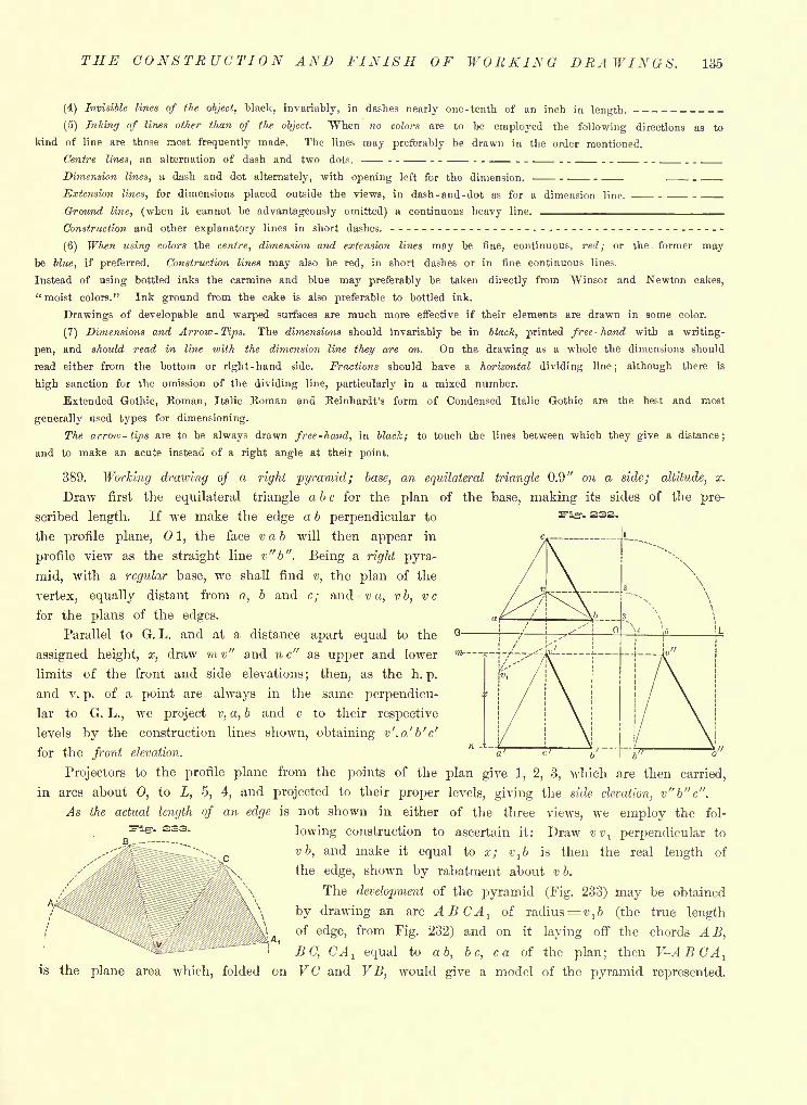
THE CONSTRUCTION AND FINISH OF WORKING DRAWINGS. 135
r- 233.
(4) Invisible lines of the object, black, invariably, in dashes nearly one-tenth of an inch in length. __________(5) Inking of lines other than of the object. When no colors are to be employed the following directions as to
kind of line are those most frequently made. The lines may preferably be drawn in the order mentioned.
Centre lines, an alternation of dash and two dots. ---------- - ---------- _____Dimension lines, a dash and dot alternately, with opening left for the dimension. ------ _.__Extension lines, for dimensions placed outside the views, in dash-and-dot as for a dimension line. _____Ground line, (when it cannot be advantageously omitted) a continuous heavy line. ^^^^_^_^^^_^^^_^_^___Construction and other explanatory lines in short dashes. --------------- - ---------- - ----------------
(6) When using colors the centre, dimension and extension lines may be fine, continuous, red; or the former maybe blue, if preferred. Construction lines may also be red, in short dashes or in fine continuous lines.
Instead of using bottled inks the carmine and blue may preferably be taken directly from "Winsor and Newton cakes,
"moist colors." Ink ground from the cake is also preferable to bottled ink.
Drawings of developable and warped surfaces are much more effective if their elements are drawn in some color.
(7) Dimensions and Arrow-Tips. The dimensions should invariably be in black, printed free-hand with a writing-
pen, and should read in line with the dimension line they are on. On the drawing as a whole the dimensions should
read either from the bottom or right-hand side. Fractions should have a horizontal dividing line; although there is
high sanction for the omission of the dividing line, particularly in a mixed number.
Extended Gothic, Roman, Italic Roman and Reinhardt's form of Condensed Italic Gothic are the best and most
generally used types for dimensioning.
The arrow- tips are to be always drawn free-hand, in black; to touch the lines between which they give a distance;
and to make an acute instead of a right angle at their point.
389. Working drawing of a right pyramid; base, an equilateral triangle 0.9" on a side; altitude, x.
Draw first the equilateral triangle a b c for the plan of the base, making its sides of the pre-
scribed length. If we make the edge a b perpendicular to
the profile plane, 01, the face vab will then appear in
profile view as the straight line v"b". Being a right pyra-
mid, with a regular base, we shall find v, the plan of the
vertex, equally distant from a, b and c; and v a, vb, vc
for the plans of the edges.
Parallel to G. L. and at a distance apart equal to the
assigned height, x, draw mv" and nc" as upper and lower
limits of the front and side elevations; then, as the h. p.
and v. p. of a point are always in the same perpendicu-
lar to G. L., we project v, a, b and c to their respective
levels by the construction lines shown, obtaining v'.a'b'c'
for the front elevation.
Projectors to the profile plane from the points of the plan give 1, 2, 3, -which are then carried,
in arcs about 0, to L, 5, 4, and projected to their proper levels, giving the side elevation, v"b"c".
As the actual length of an edge is not shown in either of the three views, we employ the fol-
lowing construction to ascertain it: Draw vvl perpendicular to
vb, and make it equal to a; vtb is then the real length of
the edge, shown by rabatment about vb.
The development of the pyramid (Fig. 233) may be obtained
by drawing an arc ABCA1
of radius= t>, b (the true length
of edge, from Fig. 232) and on it laying off the chords AS,^, '
BO, CAl equal to a b, be, ca of the plan; then V-ABCA
l
is the plane area which, folded on VC and VB, would give a model of the pyramid represented.
333-
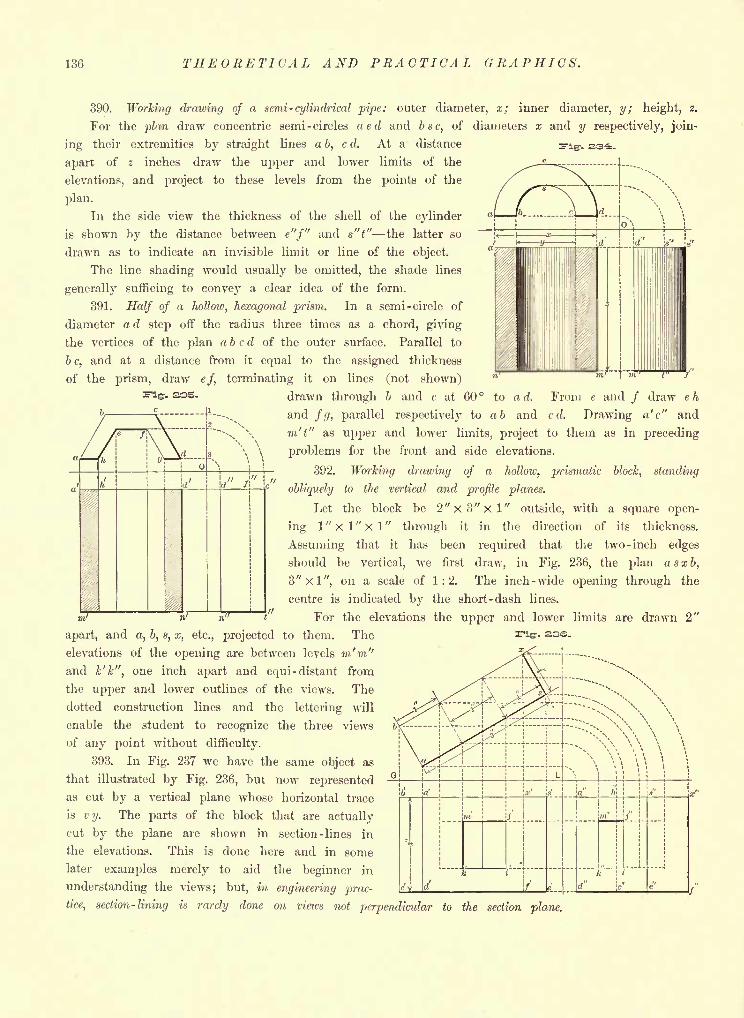
136 THEORETICAL AND PRACTICAL GRAPHICS.
- 23-3;-
390. Working drawing of a semi -cylindrical pipe: outer diameter, x; inner diameter, y; height, z.
For the plan draw concentric semi -circles aed and bsc, of diameters x and y respectively, join-
ing their extremities by straight lines a b, c d. At a distance
apart of z inches draw the upper and lower limits of the
elevations, and project to these levels from the points of the
plan.
In the side view the thickness of the shell of the cylinder
is shown by the distance between e"f" and s"t" the latter so
drawn as to indicate an invisible limit or line of the object.
The line shading would usually be omitted, the shade lines
generally sufficing to convey a clear idea of the form.
391. Half of a hollow, hexagonal prism. In a semi -circle of
diameter a d step off the radius three times as a chord, giving
the vertices of the plan abed of the outer surface. Parallel to
bc,
and at a distance from it equal to the assigned thickness
of the prism, draw ef, terminating it on lines (not shown). 335. drawn through b and c at 60 to a d. From e and / draw e h
and fg, parallel respectively to ab and c d. Drawing a' c" and
m't" as upper and lower limits, project to them as in preceding
problems for the front and side elevations.
392. Working drawing of a hollow, prismatic block, standing
obliquely to the vertical and profile planes.
Let the block be 2"x3"xl" outside, with a square open-
ing 1" x 1
" x 1"
through it in the direction of its thickness.
Assuming that it has been required that the two -inch edges
should be vertical, we first draw, in Fig. 236, the plan asxb,
3"xl", 011 a scale of 1:2. The inch -wide opening through the
centre is indicated by the short -dash lines.
B' n" t" For the elevations the upper and lower limits are drawn 2"
apart, and a, b, s, x, etc., projected to them. The
elevations of the opening are between levels m'm"and k'k", one inch apart and equi- distant from
the upper and lower outlines of the views. The
dotted construction lines and the lettering will
enable the student to recognize the three views
of any point without difficulty.
393. In Fig. 237 we have the same object as
that illustrated by Fig. 236, but now represented
as cut by a vertical plane whose horizontal trace
is v y. The parts of the block that are actually
cut by the plane are shown in section -lines in
the elevations. This is done here and in some
later examples merely to aid the beginner in
understanding the views; but, in engineering prac-
tice, section-lining is rarely done on views not perpendicular to the section plane.
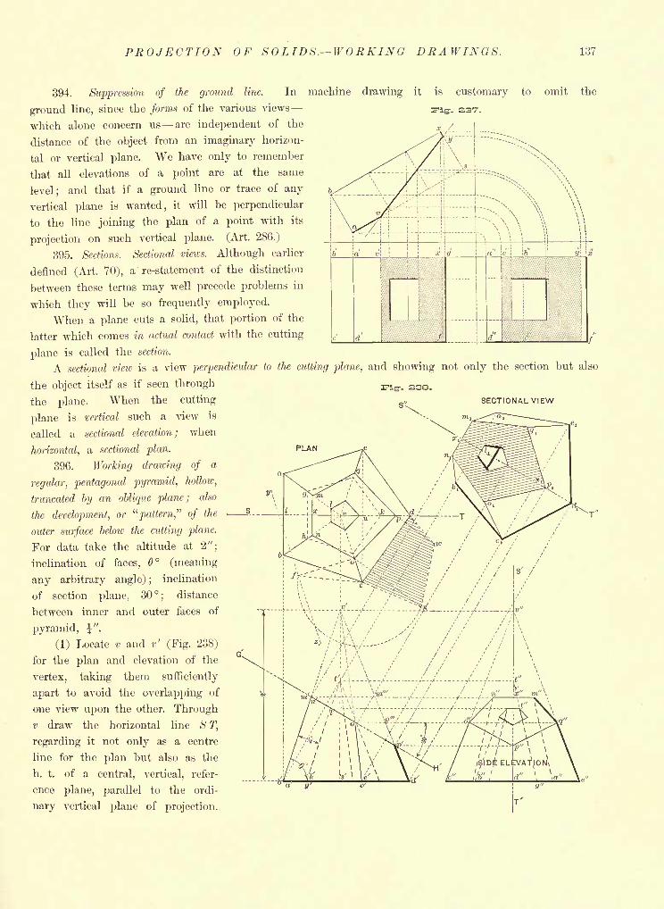
PROJECTION OF SO LIDS. WORKING DRAWINGS. 137
is customary to omit the
-. 237-.
*./. j
Ifa-
394. Suppression of the ground line. In machine drawing it
ground line, since the forms of the various views
which alone concern us are independent of the
distance of the object from an imaginary horizon-
tal or vertical plane. We have only to remember
that all elevations of a point are at the same
level; and that if a ground line or trace of any
vertical plane is wanted, it will be perpendicular
to the line joining the plan of a point with its
projection on such vertical plane. (Art. 286.)
395. Sections. Sectional views. Although earlier
defined (Art. 70), a re-statement of the distinction
between these terms may well precede problems in
which they will be so frequently employed.
When a plane cuts a solid, that portion of the
latter which comes in actual contact with the cutting
plane is called the section.
A sectional view is a view perpendicular to the cutting plane, and showing not only the section but also
the object itself as if seen through
the plane. When the cutting SECTIONAL VIEW
plane is vertical such a view is
called a sectional elevation; when
horizontal, a sectional plan.
396. Working drawing of a
regular, pentagonal pyramid, hollow,
truncated by an oblique plane; also
the development, or "pattern," of the
outer surface below the cutting plane.
For data take the altitude at 2";
inclination of faces, (meaning
any arbitrary angle); inclination
of section plane, 30; distance
between inner and outer faces of
pyramid, \" .
(1) Locate v and r' (Fig. 238)
for the plan and elevation of the
vertex, taking them sufficiently
apart to avoid the overlapping of
one view upon the other. Through
v draw the horizontal line S T,
regarding it not only as a centre
line for the plan but also as the
h. t. of a central, vertical, refer-
ence plane, parallel to the ordi-
nary vertical plane of projection.
I -V/ ;/--/--/-/- -i^
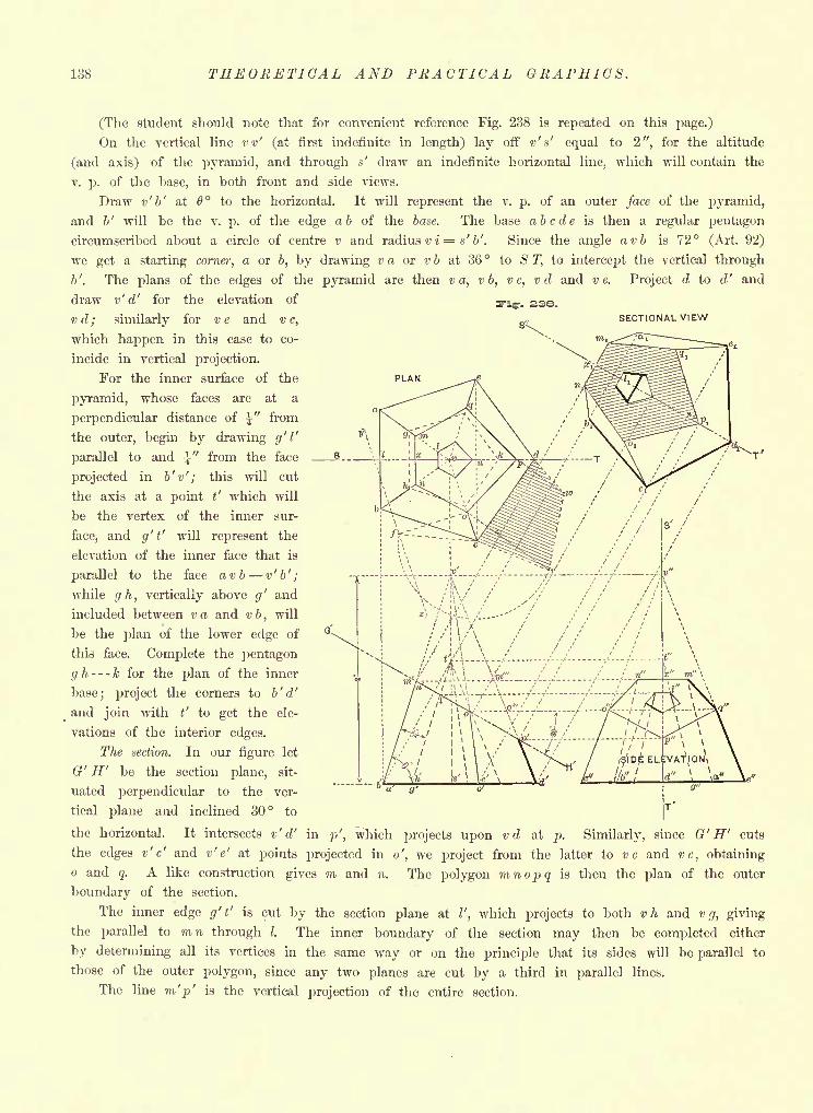
138 THEORETICAL AND PRACTICAL GRAPHICS.
SECTIONAL VIEW
PLAN
(The student should note that for convenient reference Fig. 238 is repeated on this page.)
On the vertical line vv' (at first indefinite in length) lay off v' s' equal to 2", for the altitude
(and axis) of the pyramid, and through a' draw an indefinite horizontal line, which will contain the
v. p. of the base, in both front and side views.
Draw v'b' at 6 to the horizontal. It will represent the v. p. of an outer face of the pyramid,
and b'
will be the v. p. of the edge a b of the base. The base a b c d e is then a regular pentagon
circumscribed about a circle of centre v and radius vi = s'b'. Since the angle avb is 72 (Art. 92)
we get a starting corner, a or b, by drawing v a or v b at 36 to S T, to intercept the vertical through
b'. The plans of the edges of the pyramid are then v a, vb, v c, vd and v e. Project d to d' and
draw v' d' for the elevation of
v d ; similarly for v e and v c,
which happen in this case to co-
incide in vertical projection.
For the inner surface of the
pyramid, whose faces are at a
perpendicular distance of \" from
the outer, begin by drawing g' I'
parallel to and \" from the face
projected in b' v' ; this will cut
the axis at a point t' which will
be the vertex of the inner sur-
face, and g' t' will represent the
elevation of the inner face that is
parallel to the face a v b v'
b'
;
while gh, vertically above g' and
included between va and vb, will
be the plan of the lower edge of
this face. Complete the pentagon
gh k for the plan of the inner
base; project the corners to b' d'
and join with t' to get the ele-
vations of the interior edges.
The section. In our figure let
G' H ' be the section plane, sit-
uated perpendicular to the ver-
tical plane and inclined 30 to
the horizontal. It intersects v' d' in p', which projects upon vd at p. Similarly, since G' H' cuts
the edges v' c' and v' e' at points projected in o', we project from the latter to v c and ve, obtaining
o and q. A like construction gives m and n. The polygon mnopq is then the plan of the outer
boundary of the section.
The inner edge g' t' is cut by the section plane at I', which projects to both v h and v g, giving
the parallel to mn through I. The inner boundary of the section may then be completed either
by determining all its vertices in the same way or on the principle that its sides will be parallel to
those of the outer polygon, since any two planes are cut by a third in parallel lines.
The line m'p' is the vertical projection of the entire section.
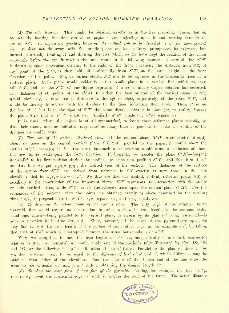
PROJECTION OF SOLIDS. WORKING DRAWINGS. 139
(2) The side elevation. This might be obtained exactly as in the five preceding figures, that is,
by actually locating the side vertical, or profile, plane, projecting upon it and rotating through an
arc of 90. In engineering practice, however, the method now to be described is in Jar more general
use. It does not do away with the profile plane, on the contrary presupposes its existence, but
instead of actually locating it and drawing the arcs which so far have kept the relation of the views
constantly before the eye, it reaches the same result in the following manner : A vertical line S' T'
is drawn at some convenient distance to the right of the front elevation;
the distance, from S T, of
any point of the plan, is then laid off horizontally from iS" T", at the same height as the front
elevation of the point. For, as earlier stated, S T was to be regarded as the horizontal trace of a
vertical plane. Such plane would evidently cut a profile plane in a vertical line, which we maycall S' T', and let the S' T' of our figure represent it after a ninety -degree rotation has occurred.
The distances of all points of the object, to either the front or rear of the vertical plane on S T
would, obviously, be now seen as distances to the left or right, respectively, of the trace S' T', and
would be directly transferred with the dividers to the lines indicating their level. Thus, e" is on
the level of e', but is to the right of S' T' the same distance that e is above (or, in reality, behind)
the plane ST; that is, e" d" equals eit. Similarly d"b" equals ib; n"x" equals nx.
It is usual, where the object is at all symmetrical, to locate these reference planes centrally, so
that their traces, used as indicated, may bisect as many lines as possible, to make one setting of the
dividers do double work.
(3) True size of the section. Sectional mew. If the section plane G' H' were rotated directly
about its trace on the central, vertical plane <Sr
T, until parallel to the paper, it would show the
section in' p' mnopq in its true size; but such a construction would cause a confusion of lines,
the new figure overlapping the front elevation. If, however, we transfer the plane G' H' keeping
it parallel to its first position during the motion to some new position S"T", and then turn it 90
on that line, we get m,ln
lo
l p 1 q l ,the desired view of the section. The distances of the vertices
of the section from S" T" are derived from reference to S T exactly as were those in the side
elevation; that is, m lx
1= mx = m"x". We thus see that one central, vertical, reference plane, ST, is
auxiliary to the construction of two important views;
<S" T' represents its intersection with the profile
or side vertical plane, while S" T" is its (transferred) trace upon the section plane G'H'. For the
remainder of the sectional view the points are obtained exactly as above described for the section;
thus c'cle
lis perpendicular to S"T"; e
tti
l equals eu, and clu
1 equals CM.
(4) To determine the actual length of the various edges. The only edge of the original, uncut
pyramid, that would require no construction in order to show its true length, is the extreme right-
hand one, which being parallel to the vertical plane, as shown by its plan v d being horizontal is
seen in elevation in its true size, v'd'. Since, however, all the edges of the pyramid are equal, we
may find on v'd' the true length of any portion of some other edge, as, for example o'c', by taking
that part of v'd' which is intercepted between the same horizontals, viz.: o'"d'.
Were we compelled to find the true length of o'c', oc, independently of any such convenient
relation as that just indicated, we would apply one of the methods fully illustrated by Figs. 183, 184
and 187, or the following"shop
" modification of one of them : Parallel to the plan o c draw a line
i/z, their distance apart to be equal to the difference of level of o' and c', which difference may be
obtained from either of the elevations;
from the plan o of the higher end of the line draw the
common perpendicular of, and join / with c, obtaining the desired length fc.
(5) To show the exact form of any fare of the pyramid. Taking, for example, the face ocdp,
revolve o p about the horizontal edge c d until it reaches the level of the latter. The actual distance
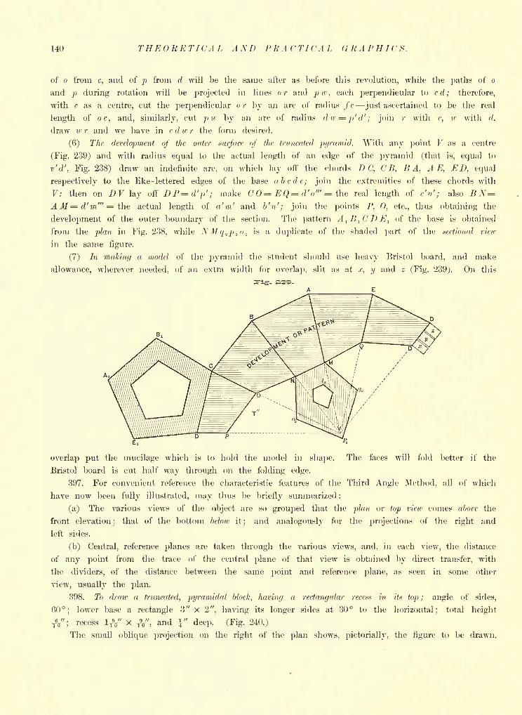
140 THEORETICAL AM) PRACTICAL GRAPHICS.
of o from c, and of p from d will be the same after as before this revolution, while the paths of o
and p during rotation will be projected in lines or and ptc, each perpendicular to cd; therefore,
with c as a centre, cut the perpendicular or by an arc of radius fc just ascertained to be the real
length of or, and, similarly, cut p w by an arc of radius dw^p'd'i join / with c, w with d.
draw w r and we have in c d >r r the form desired.
(6) The development of the outer xtirfacc of the truncated pyramid. With any point V as a centre
(Fig. 239) and with radius equal to the actual length of an edge of the pyramid (that is, equal to
v'd', Fig. 238) draw an indefinite arc, on which lay off the chords D C, C B, HA, A E, ED, equal
respectively to the like - lettered edges of the base abcde; join the extremities of these chords with
V: then on D V lay off DP=d'p'; make C0= EQ= d' o'" = the real length of c'o'; also B X=A M= d'm'" = the actual length of a'm' and b'n'; join the points /', 0, etc., thus obtaining the
development of the outer boundary of the section. The pattern A1B
1CDE
1of the base is obtained
from the plan in Fig. 238, while XM/j.2 p.,o., is a duplicate of the shaded part of the xectioiial view
in the same figure.
(7) In making a model of the pyramid the student should use heavy Bristol board, and make
allowance, wherever needed, of an extra width for overlap, slit as at.c, y and z (Fig. 239). On this
r. ESS-
overlap put the mucilage which is to hold the model in shape. The faces will fold better if the
Bristol board is cut half way through on the folding edge.
397. For convenient reference the characteristic features of the Third Angle Method, all of which
have now been fully illustrated, may thus be briefly summarized :
(a) The various views of the object are so grouped that the plan or top view comes abore the
front elevation; that of the bottom below it; and analogously for the projections of the right and
left sides.
(b) Central, reference planes are taken through the various views, and, in each view, the distance
of any point from the trace of the central plane of that view is obtained by direct transfer, with
the dividers, of the distance between the same point and reference plane, as seen in some other
view, usually the plan.
398. To draw a truncated, pyramidal block, having a rectangular retex* in its top; angle of sides,
60; lower base a rectangle 3" x 2", having its longer sides at 30 to the horizontal; total height
&"; recess 1^" X ft", and \" deep. (Fig. 240.)
The small oblique projection on the right of the plan shows, pictorially, the figure to be drawn.
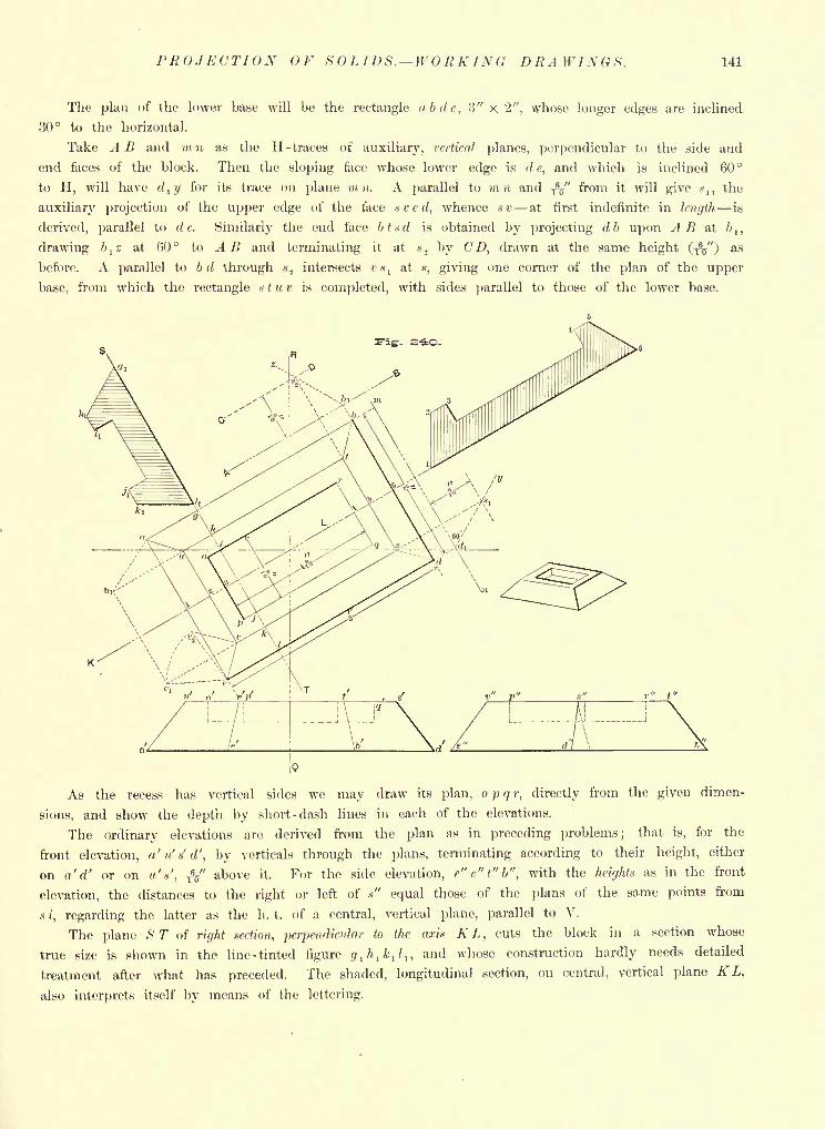
PROJECTION OF SOLIDS. WORKING DRAWINGS. 141
The plan of the lower base will be the rectangle abdc, ?>" x 2", whose longer edges are inclined
30 to the horizontal.
Take A B and mn as the H- traces of auxiliary, vertical planes, perpendicular to the side and
end faces of the block. Then the sloping face whose lower edge is d e, and which is inclined 60
to H, will have dt y for its trace on plane m u. A parallel to mn and ^" from it will give x,, the
auxiliary projection of the upper edge of the face vved, whence sv at first indefinite in length is
derived, parallel to de. Similarly the end face btxd is obtained by projecting db upon A B at ft,,
drawing ft,z at (50 to A B and terminating it at *, by CD, drawn at the same height (-$") as
before. A parallel to bd through *2 intersects ex, at *, giving one corner of the plan of the upper
base, from which the rectangle * t u v is completed, with sides parallel to those of the lower base.
As the recess has vertical sides we may draw its plan, o p q r, directly from the given dimen-
sions, and show the depth by short -dash lines in each of the elevations.
The ordinary elevations are derived from the plan as in preceding problems; that is, for the
front elevation, a'u's'd', by verticals through the plans, terminating according to their height, either
on n'd' or on '', fi," above it. For the side elevation, e"v"t"b", with the heights as in the front
elevation, the distances to the right or left of x" equal those of the plans of the same points from
/, regarding the latter as the h. t, of a central, vertical plane, parallel to V.
The plane ST of right .-section, perpendicular to the aria KL, cuts the block in a section whose
true size is shown in the line -tinted figure r/, /i, k, /,, and whose construction hardly needs detailed
treatment after what has preceded. The shaded, longitudinal section, on central, vertical plane K L,
also interprets itself by means of the lettering.
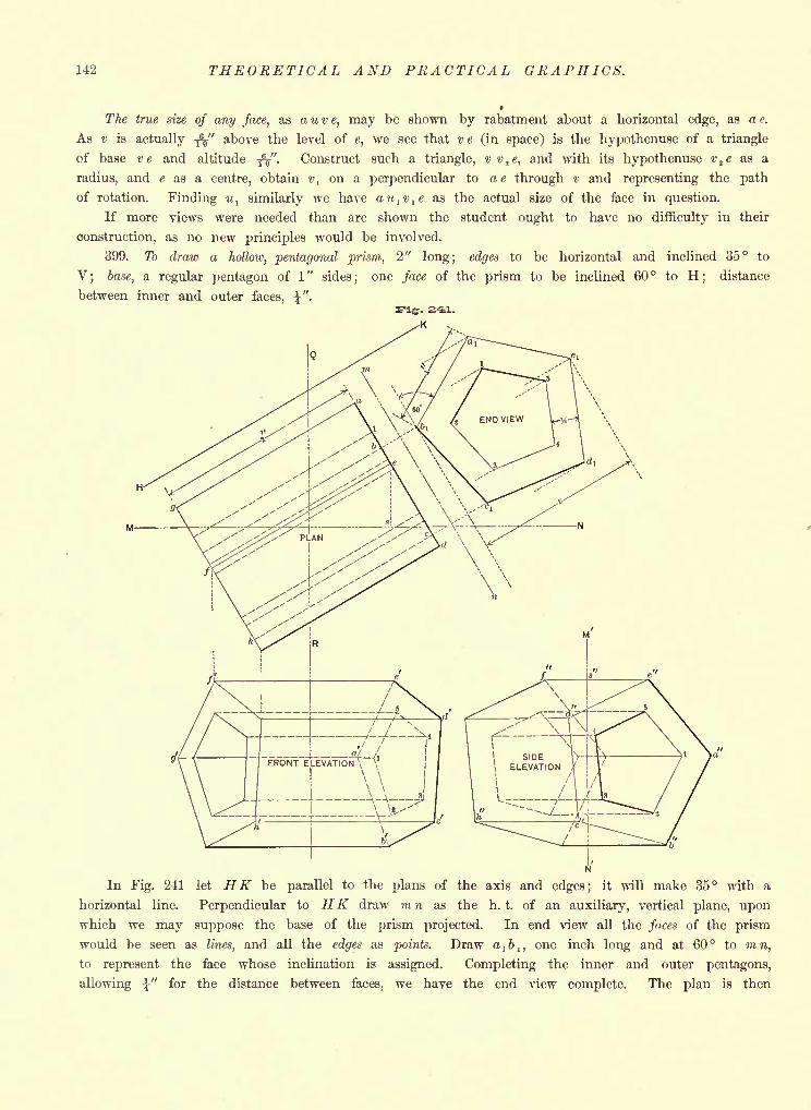
142 THEORETICAL AND PRACTICAL GRAPHICS.
The true size of any face, as a u v e, may be shown by rabatment about a horizontal edge, as a e.
As v is actually -jY' above the level of e, we see that ve (in space) is the hypothenuse of a triangle
of base ve and altitude -fa". Construct such a triangle, v v,e, and with its hypothenuse 2e as a
radius, and e as a centre, obtain i>, on a perpendicular to ae through v and representing the path
of rotation. Finding ul similarly we have au
lv
le as the actual size of the face in question.
If more views were needed than are shown the student ought to have no difficulty in their
construction, as no new principles would be involved.
399. To draw a hollow, pentagonal prism, 2" long; edges to be horizontal and inclined 35 to
V; base, a regular pentagon of 1
"sides
;one face of the prism to be inclined 60 to H
;distance
between inner and outer faces,
In Fig. 241 let HK be parallel to the plans of the axis and edges; it will make 35 with a
horizontal line. Perpendicular to HK draw m n as the h. t. of an auxiliary, vertical plane, uponwhich we may suppose the base of the prism projected. In end view all the faces of the prism
would be seen as lines, and all the edges as points. Draw a1b
l ,one inch long and at 60 to mn,
to represent the face whose inclination is assigned. Completing the inner and outer pentagons,
allowing \" for the distance between faces, we have the end view complete. The plan is then
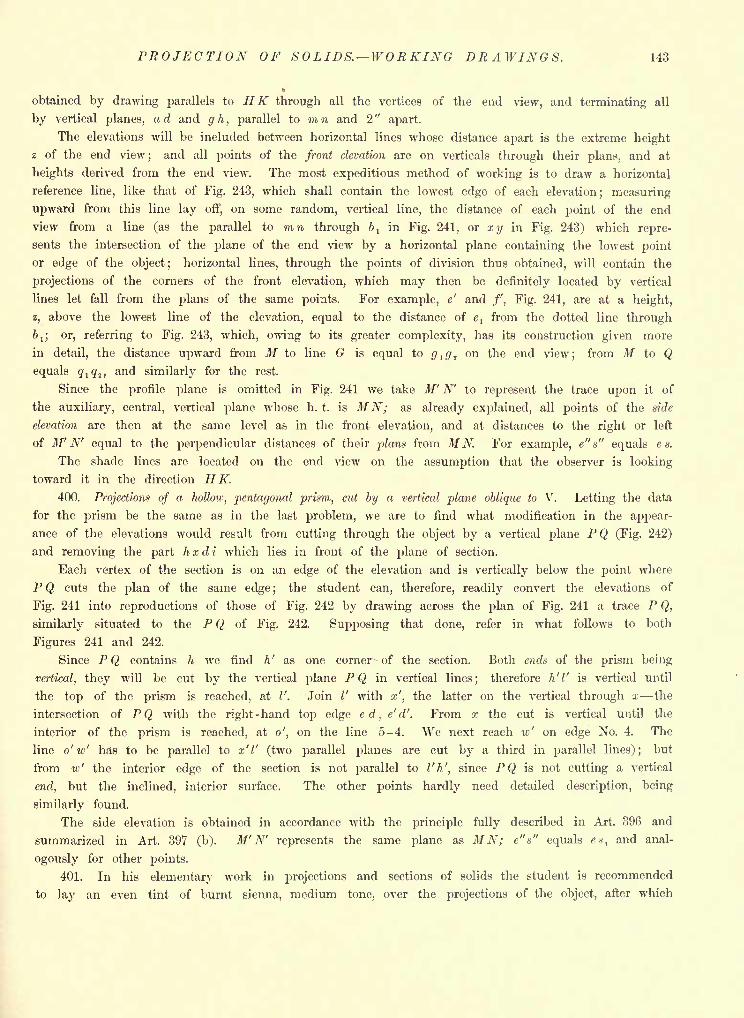
PROJECTION OF SOLIDS. WORKING DRAWINGS. 143
t
obtained by drawing parallels to HK through all the vertices of the end view, and terminating all
by vertical planes, a d and g h, parallel to m n and 2
"apart.
The elevations will be included between horizontal lines whose distance apart is the extreme height
z of the end view; and all points of the front elevation are on verticals through their plans, and at
heights derived from the end view. The most expeditious method of working is to draw a horizontal
reference line, like that of Fig. 243, which shall contain the lowest edge of each elevation; measuring
upward from this line lay off, on some random, vertical line, the distance of each point of the end
view from a line (as the parallel to mn through bl
in Fig. 241, or xy in Fig. 243) which repre-
sents the intersection of the plane of the end view by a horizontal plane containing the lowest point
or edge of the object; horizontal lines, through the points of division thus obtained, will contain the
projections of the corners of the front elevation, which may then be definitely located by vertical
lines let fall from the plans of the same points. For example, e' and /', Fig. 241, are at a height,
z, above the lowest line of the elevation, equal to the distance of elfrom the dotted line through
bl ; or, referring to Fig. 243, which, owing to its greater complexity, has its construction given more
in detail, the distance upward from M to line G is equal to #,</., on the end view; from M to Q
equals q l q 2 ,and similarly for the rest.
Since the profile plane is omitted in Fig. 241 we take M' N' to represent the trace upon it of
the auxiliary, central, vertical plane whose h. t. is MN; as already explained, all points of the side
elevation are then at the same level as in the front elevation, and at distances to the right or left
of M' N' equal to the perpendicular distances of their plans from MN. For example, e"s" equals e s.
The shade lines are located on the end view on the assumption that the observer is looking
toward it in the direction HK.400. Projections of a hollow, pentagonal prism, cut by a vertical plane oblique to V. Letting the data
for the prism be the same as in the last problem, we are to find what modification in the appear-
ance of the elevations would result from cutting through the object by a vertical plane PQ (Fig. 242)
and removing the part hxdi which lies in front of the plane of section.
Each vertex of the section is on an edge of the elevation and is vertically below the point where
P Q cuts the plan of the same edge ;the student can, therefore, readily convert the elevations of
Fig. 241 into reproductions of those of Fig. 242 by drawing across the plan of Fig. 241 a trace P Q,
similarly situated to the P Q of Fig. 242. Supposing that done, refer in what follows to both
Figures 241 and 242.
Since P Q contains h we find h' as one corner of the section. Both ends of the prism being
vertical, they will be cut by the vertical plane PQ in vertical lines; therefore h'l' is vertical until
the top of the prism is reached, at I'. Join V with x', the latter on the vertical through x the
intersection of PQ with the right-hand top edge ed, e'd'. From x the cut is vertical until the
interior of the prism is reached, at o', on the line 5-4. We next reach iv' on edge No. 4. The
line o'w' has to be parallel to x'l' (two parallel planes are cut by a third in parallel lines); but
from w' the interior edge of the section is not parallel to I'h', since PQ is not cutting a vertical
end, but the inclined, interior surface. The other points hardly need detailed description, being
similarly found.
The side elevation is obtained in accordance with the principle fully described in Art. 396 and
summarized in Art. 397 (b). M' N' represents the same plane as MN; e"s" equals es, and anal-
ogously for other points.
401. In his elementary work in projections and sections of solids the student is recommended
to lay an even tint of burnt sienna, medium tone, over the projections of the object, after which
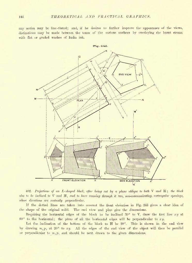
144 THEORETICAL AND PRACTICAL GRAPHICS.
any section may be line-tinted; and, if he desires to further improve the appearance of the views,
distinctions may be made between the tones of the various surfaces by overlaying the burnt sienna
with flat or graded washes of India ink.
SIDE ELEVATION
IN'
402. Projections of an L- shaped block, after being cut by a plane oblique to both V and H; the block
ako to be inclined to V and H, and to have running through it two, non-communicating, rectangular openings,
whose directions are mutually perpendicular.
If the dotted lines are taken into account the front elevation in Fig. 243 gives a clear idea of
the shape of the original solid. The end view and plan give the dimensions.
Requiring the horizontal edges of the block to be inclined 30 to V, draw the first line xy at
60 to the horizontal; the plans of all the horizontal edges will be perpendicular to xy.
Let the inclination of the bottom of the block to H be 20. This is shown in the end view
by drawing ml p l
at 20 to xy. All the edges of the end view of the object will then be parallel
or perpendicular to ml p l
and should be next drawn to the given dimensions.
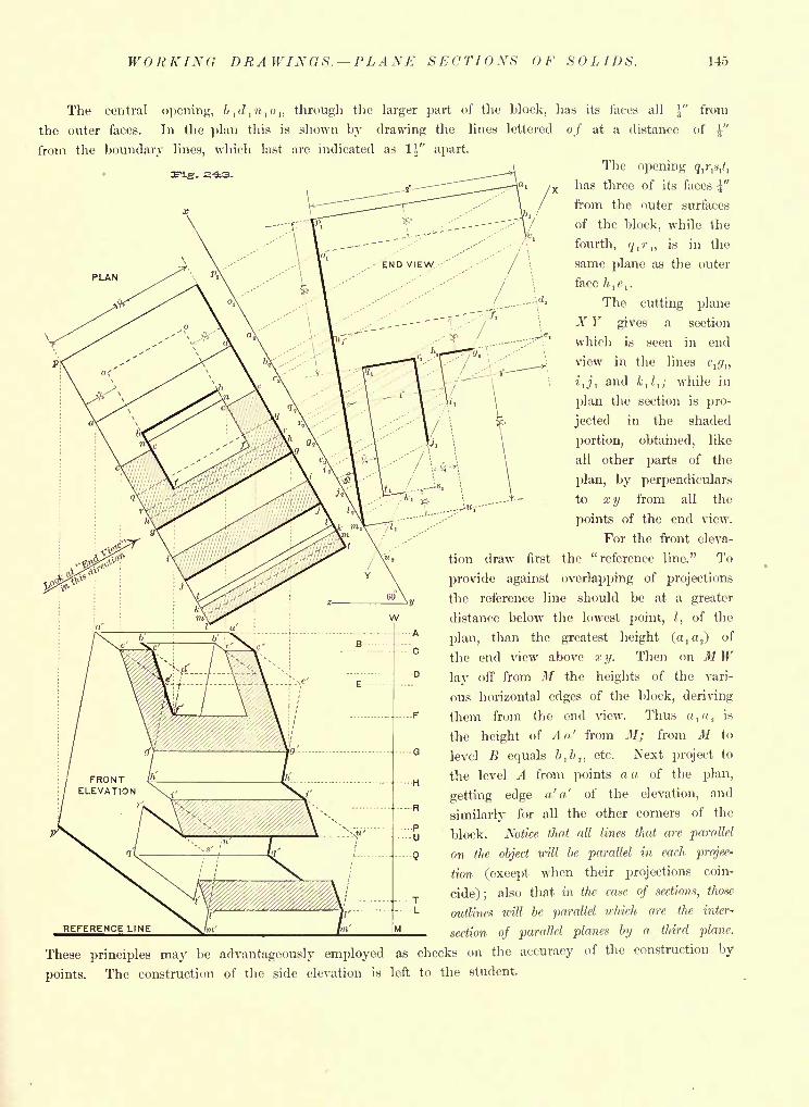
WORKING DRAWINGS. PLANE SECTIONS OF SOLIDS. 145
PLAN
The central opening, b,d t ,<>,, through the larger part of the block, has its faces all ^" from
the outer faces. In the plan this is shown by drawing the lines lettered of at a distance of \"
from the boundary lines, which last are indicated as H" apart.
The opening q^s,*,
has three of its faces i"
from the outer surfaces
of the block, while the
fourth, <?,-,, is in the
same plane as the outer
face h,e
,.
The cutting plane
A"" F gives a section
which is seen in end
view in the lines e^,,
i1 j l
and ,?,; while in
plan the section is pro-
\ :K- jected in the shaded'
\ portion, obtained, like
\ all other parts of the
\\ plan, by perpendiculars
\-* to xy from all the
. :'M'\"
points of the end view.
For the front eleva-
tion draw first the "reference line." To
provide against overlapping of projections
the reference line should be at a greater
distance below the lowest point, /, of the
plan, than the greatest height (, 2) of
the end view above x y. Then on MWlay off from M the heights of the vari-
ous horizontal edges of the block, deriving
them from the end view. Thus a,a.2is
the height of An' from M; from M to
level B equals bj>.n etc. Next project to
the level A from points a a of the plan,
getting edge a' a' of the elevation, and
similarly for all the other corners of the
block. Notice that all lines that are parallel
on the object will be parallel in each projec-
tion (except when their projections coin-
cide); also that in the case of sections, those
outlines will be parallel which are the inter-
section of parallel planes by a third plane.
These principles may be advantageously employed as checks on the accuracy of the construction by
points. The construction of the side elevation is left to the student.
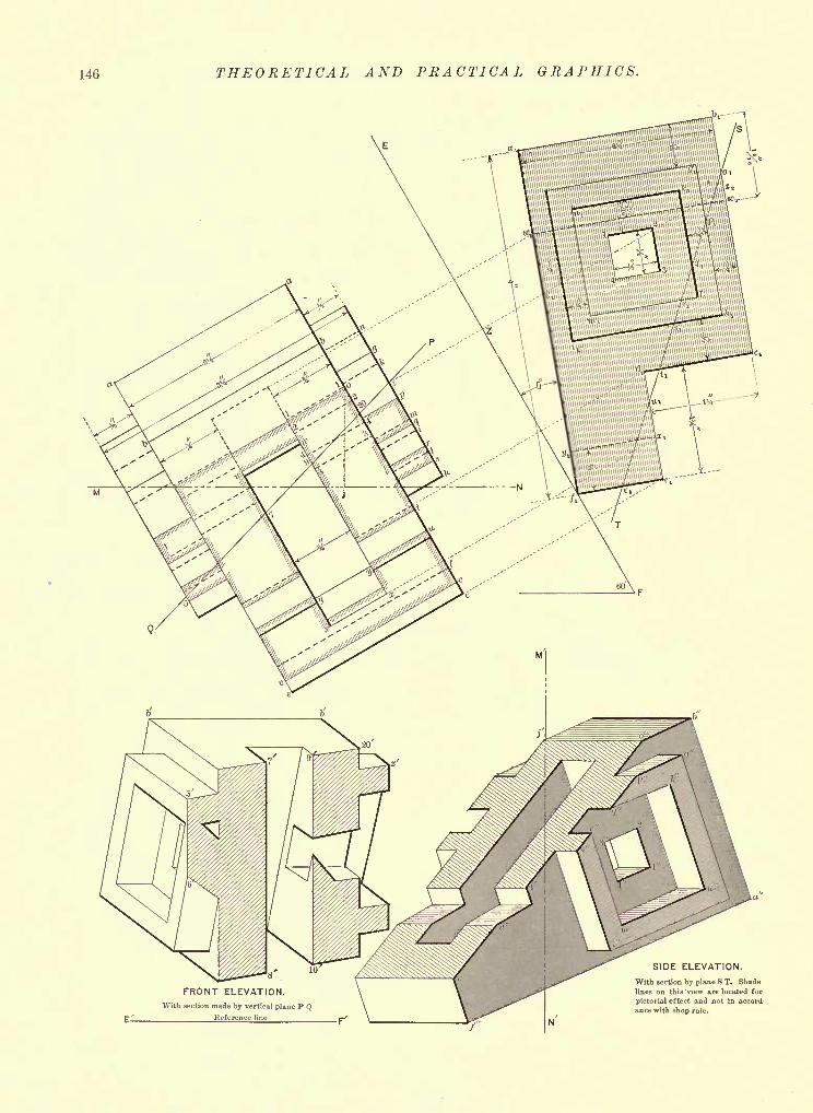
146 THEORETICAL AND PRACTICAL GRAPHICS.
E
FRONT ELEVATION.With section made by vertical plane P Q
Reference line
SIDE ELEVATION.
With section by plane S T. Shade
lines on this view are located for
pictorial effect and not in accord-
ance with shop rule.
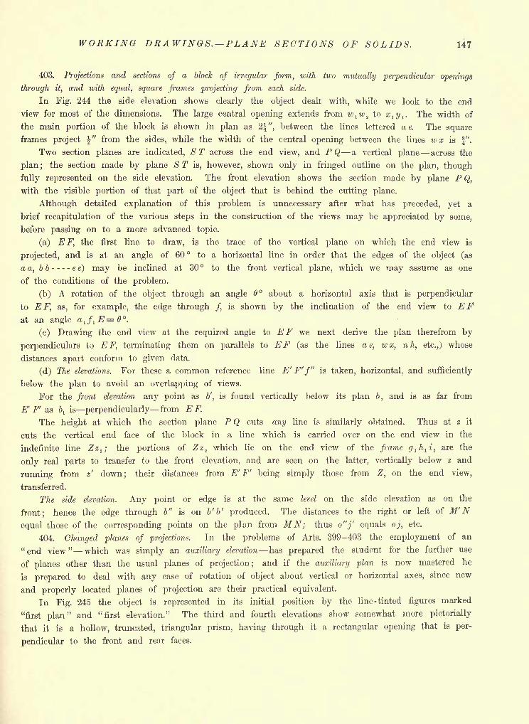
WORKING DRAWINGS. PLANE SECTIONS OF SOLIDS. 147
403. Projections and sections of a block of irregular form, with two mutually perpendicular openings
through it, and with equal, square frames projecting from each side.
In Fig. 244 the side elevation shows clearly the object dealt with, while we look to the end
view for most of the dimensions. The large central opening extends from w,w sto x
l y l. The width of
the main portion of the block is shown in plan as 2^", between the lines lettered ae. The square
frames project |" from the sides, while the width of the central opening between the lines wx is f".
Two section planes are indicated, S T across the end view, and P Q a vertical plane across the
plan ;the section made by plane S T is, however, shown only in fringed outline on the plan, though
fully represented on the side elevation. The front elevation shows the section made by plane P Q,
with the visible portion of that part of the object that is behind the cutting plane.
Although detailed explanation of this problem is unnecessary after what has preceded, yet a
brief recapitulation of the various steps in the construction of the views may be appreciated by some,
before passing on to a more advanced topic.
(a) E F, the first line to draw, is the trace of the vertical plane on which the end view is
projected, and is at an angle of 60 to a horizontal line in order that the edges of the object (as
a a, bb ee) may be inclined at 30 to the front vertical plane, which we may assume as one
of the conditions of the problem.
(b) A rotation of the object through an angle 6 about a horizontal axis that is perpendicular
to E F, as, for example, the edge through /, is shown by the inclination of the end view to EFat an angle a
l / lE=0.
(c) Drawing the end view at the required angle to EF we next derive the plan therefrom by
perpendiculars to E F, terminating them on parallels to EF (as the lines ae, wx, nh, etc.,) whose
distances apart conform to given data.
(d) The elevations. For these a common reference line E' F'f" is taken, horizontal, and sufficiently
below the plan to avoid an overlapping of views.
For the front elevation any point as b', is found vertically below its plan 6, and is as far from
E' F' as bl
is perpendicularly from E F.
The height at which the section plane P Q cuts any line is similarly obtained. Thus at z it
cuts the vertical end face of the block in a line which is carried over on the end view in the
indefinite line Zz2 ; the portions of Zz
2 which lie on the end view of the frame g ih
li
lare the
only real parts to transfer to the front elevation, and are seen on the latter, vertically below z and
running from z' down; their distances from E' F' being simply those from Z, on the end view,
transferred.
The side elevation. Any point or edge is at the same level on the side elevation as on the
front; hence the edge through b" is on b' b' produced. The distances to the right or left of M'Nequal those of the corresponding points on the plan from MN; thus o"j' equals oj, etc.
404. Changed planes of projections. In the problems of Arts. 399-403 the employment of an
"end view" which was simply an auxiliary elevation has prepared the student for the further use
of planes other than the usual planes of projection; and if the auxiliary plan is now mastered he
is prepared to deal with any case of rotation of object about vertical or horizontal axes, since new
and properly located planes of projection are their practical equivalent.
In Fig. 245 the object is represented in its initial position by the line-tinted figures marked
"first plan" and "first elevation." The third and fourth elevations show somewhat more pictorially
that it is a hollow, truncated, triangular prism, having through it a rectangular opening that is per-
pendicular to the front and rear faces.
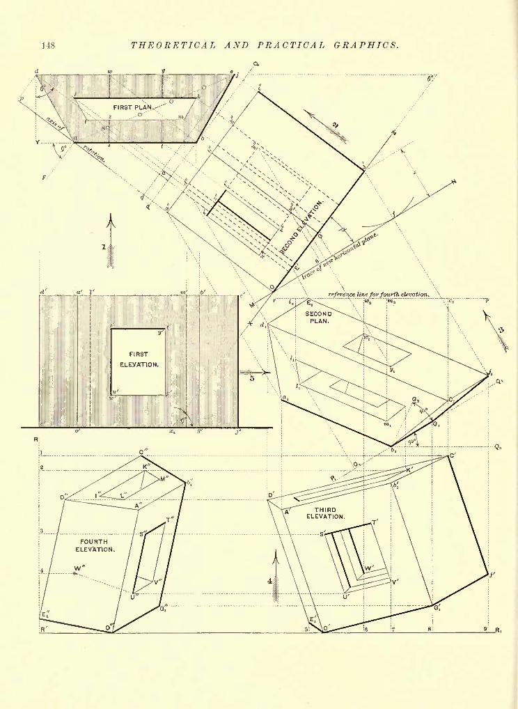
148 THEORETICAL AND PRACTICAL GRAPHICS.
reference line for fourth elevation. \" "
R,
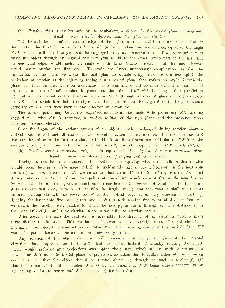
CHANGING PROJECTION-PLANE EQUIVALENT TO ROTATING OBJECT. 149
(a) Rotation about a vertical axis, or its equivalent, a change in the vertical plane of projection.
Kesult : second elevation derived from first plan and elevation.
Let the axis be one of the vertical edges of the object, as that at d in the first plan ;also let
the rotation be through an angle Ydo or 6, (6 being taken, for convenience, equal to the angle
YaF, which with the line pq will be employed in a later construction). If we were actually to
rotate the object through an angle 6 the new plan would be the exact counterpart of the first, but
its horizontal edges would make an angle 6 with their former direction, and the new elevation
would partly overlap the first one. To avoid the latter unnecessary complication, as also the
duplication of the plan, we make the first plan do double duty, since we can accomplish the
equivalent of rotation of the object by taking a new vertical plane that makes an angle with the
plane on which the first elevation was made. This equivalence will be more evident if some small
object, as a piece of india rubber, is placed on the "first plan
" with its longer edges parallel to
a b, and is then viewed in the direction of arrow No. 2 through a pane of glass standing vertically
on XZ; after which turn both the object and the glass through the angle 6 until the glass stands
vertically on e'j' and then view in the direction of arrow No. 1.
The second plane may be located anywhere, as long as the angle 6 is preserved; XZ, making
angle & at xlwith e'j', is, therefore, a random position of the new plane, and the projection upon
it is our "second elevation."
Since the heights of the various corners of an object remain unchanged during rotation about a
vertical axis we will find all points of the second elevation at distances from the reference line XZthat are derived from the first elevation, and laid off on lines drawn perpendicular to XZ from the
vertices of the plan: thus a is perpendicular to XZ, and a" equals o'a'; c"J' equals e'j', etc.
(b) Rotation about a horizontal axis, or its equivalent, the adoption of a new horizontal plane.
Result : second plan derived from first plan and second elevation.
Having in the last case illustrated the method of complying with the condition that rotation
should occur through a given angle (which is incidentally shown again, however, in the next con-
struction) we now choose an axis p q so as to illustrate a different kind of requirement, viz. : that
during rotation the heights of any two points of the object, which were at first at the same level as
the axis, shall be in some predetermined ratio, regardless of the amount of rotation. In the figure
it is assumed that e'(rf) is to be at one-fifth the height of j'j, and that rotation shall occur about
an axis passing through the lower end o' of the vertical edge at a. By drawing ad and aj,
dividing the latter into five equal parts, and joining d with n the first point of division from a -
we obtain the direction dn, parallel to which the axis p q is drawn through o. The distance dp is
then one -fifth of jq, and they shorten in the same ratio, as rotation occurs.
After locating the axis the next step is, invariably, the drawing of an elevation upon a plane
perpendicular to the axis. This we happen, however, to have already in our " second elevation,"
having, in the interest of compactness, so taken 6 in the preceding case that the vertical plane XZwould be perpendicular to the axis we are now ready to use.
Any rotation of the object about p q will, evidently, not change the form of the " second
elevation" but simply incline it to XZ. But, as before, instead of actually rotating the object,
which would probably give projections overlapping those from which we are working, we adopt a
new plane MN as a horizontal plane of projection, so taken that it fulfills either of the following
conditions: (a) that the object should be rotated about p q through an angle J' N = ft; (b)
that the corner J' should be higher f" n by an amount x, MN being drawn tangent to an
arc having J' for its centre, and J'f to x) for its radius.
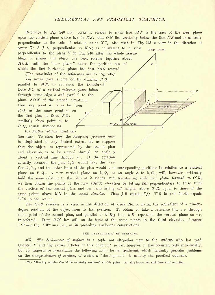
THEORETICAL AND PRACTICAL GRAPHICS.
Reference to Fig. 246 may make it clearer to some that AT TV is the trace of the new plane
upon the vertical plane whose h. t. is XZ; that ON lies vertically below the line XZ and is as truly
perpendicular to the axis of rotation as is XZ; also that in Fig. 245 a view in the direction of
arrow No. 3 (i. e., perpendicular to MN) is equivalent to a view
perpendicular to the plane V in Fig. 246 after the whole assem-
blage of planes and object has been rotated together about
HOH until the "new plane" takes the position out of
which the first horizontal plane has just been rotated.
(The remainder of the references are to Fig. 245.)
The second plan is obtained by drawing Pl Q 17
parallel to MN, to represent the transferred
trace PQ of a vertical reference plane taken
through some edge b and parallel to the
plane Z N of the second elevation;
then any point dl
is as far from
Pl Q ,
as the same point d on
the first plan is from P Q ;
similarly, from point wl
to
Pj Q, equals distance wb.
(c) Further rotation about ver-
tical axes. To show how the foregoing processes maybe duplicated to any desired extent let us suppose
that the object, as represented by the second plan
and elevation, is to be rotated through an angle <f>
about a vertical line through &,. If the rotation
actually occurred, the plan b1G
lwould take the posi-
tion bl G^, and the other lines of the plan would take corresponding positions in relation to a vertical
plane on PjQ,. A new vertical plane on bl Q 3 ,
at an angle < to blG
1 , will, however, evidently
hold the same relation to the plan as it stands, and transferring such new plane forward to 0' Rj
we then obtain the points of the new (third) elevation by letting fall perpendiculars to 0' Rlfrom
the vertices of the second plan, and on them laying off heights above 0' Rl equal to those of the
same points above MN in the second elevation. Thus j' 9 equals J'f; W 6 in the fourth equals
W"G in the second.
The fourth elevation is a view in the direction of arrow No. 5, giving the equivalent of a ninety-
degree rotation of the object from its last position. To obtain it take a reference line r r through
some point of the second plan, and parallel to 0' R l ;then R R' represents the vertical plane on r r,
transferred. From R R' lay off on the levels of the same points in the third elevation distance
lC"'=c,C1 j4W" = w
2w I) as in preceding analogous constructions.
THE DEVELOPMENT OF SURFACES.
405. The development of surfaces is a topic not altogether new to the student who has read
Chapter V and the earlier articles of this chapter;* so far, however, it has occurred only incidentally,
but its importance necessitates the following more formal treatment, which naturally precedes problems
on the interpenetration of surfaces, of which a "development
"is usually the practical outcome.
*The following articles should be carefully reviewed at this point: 120; 191; 344-6; 389, and Case 6 of Art. 396.
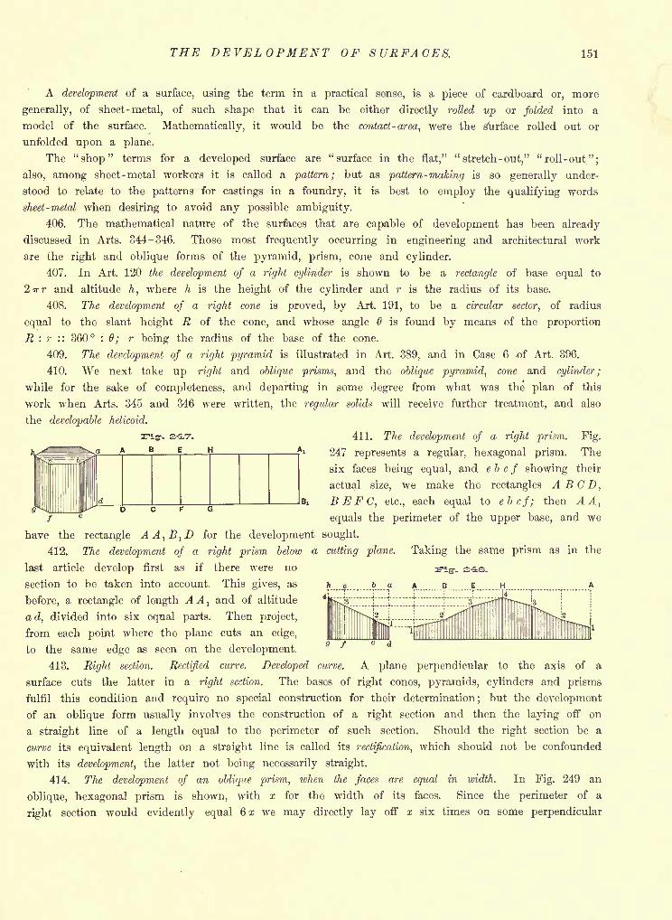
THE DEVELOPMENT OF SURFACES. 151
A development of a surface, using the term in a practical sense, is a piece of cardboard or, more
generally, of sheet -metal, of such shape that it can be either directly rolled up or folded into a
model of the surface. Mathematically, it would be the contact- area, were the Surface rolled out or
unfolded upon a plane.
The "shop" terms for a developed surface are "surface in the flat," "stretch-out," "roll -out";
also, among sheet -metal workers it is called a pattern; but as pattern-making is so generally under-
stood to relate to the patterns for castings in a foundry, it is best to employ the qualifying words
sheet- metal when desiring to avoid any possible ambiguity.
406. The mathematical nature of the surfaces that are capable of development has been already
discussed in Arts. 344-346. Those most frequently occurring in engineering and architectural work
are the right and oblique forms of the pyramid, prism, cone and cylinder.
407. In Art. 120 the development of a right cylinder is shown to be a rectangle of base equal to
2irr and altitude h, where h is the height of the cylinder and r is the radius of its base.
408. The development of a right cone is proved, by Art. 191, to be a circular sector, of radius
equal to the slant height R of the cone, and whose angle 6 is found by means of the proportion
R : r :: 360 : 0; r being the radius of the base of the cone.
409. The development of a right pyramid is illustrated in Art. 389, and in Case 6 .of Art. 396.
410. We next take up right and oblique prisms, and the oblique pyramid, cone and cylinder;
while for the sake of completeness, and departing in some degree from what was the plan of this
work when Arts. 345 and 346 were written, the regular solids will receive further treatment, and also
the developable helicoid.
411. The development of a right prism. Fig.
247 represents a regular, hexagonal prism. The
six faces being equal, and e b c f showing their
actual size, we make the rectangles A B GD,
BEFC, etc., each equal to ebcf; then AAl
equals the perimeter of the upper base, and we
ngr. E-i'7-
a A B E H A!
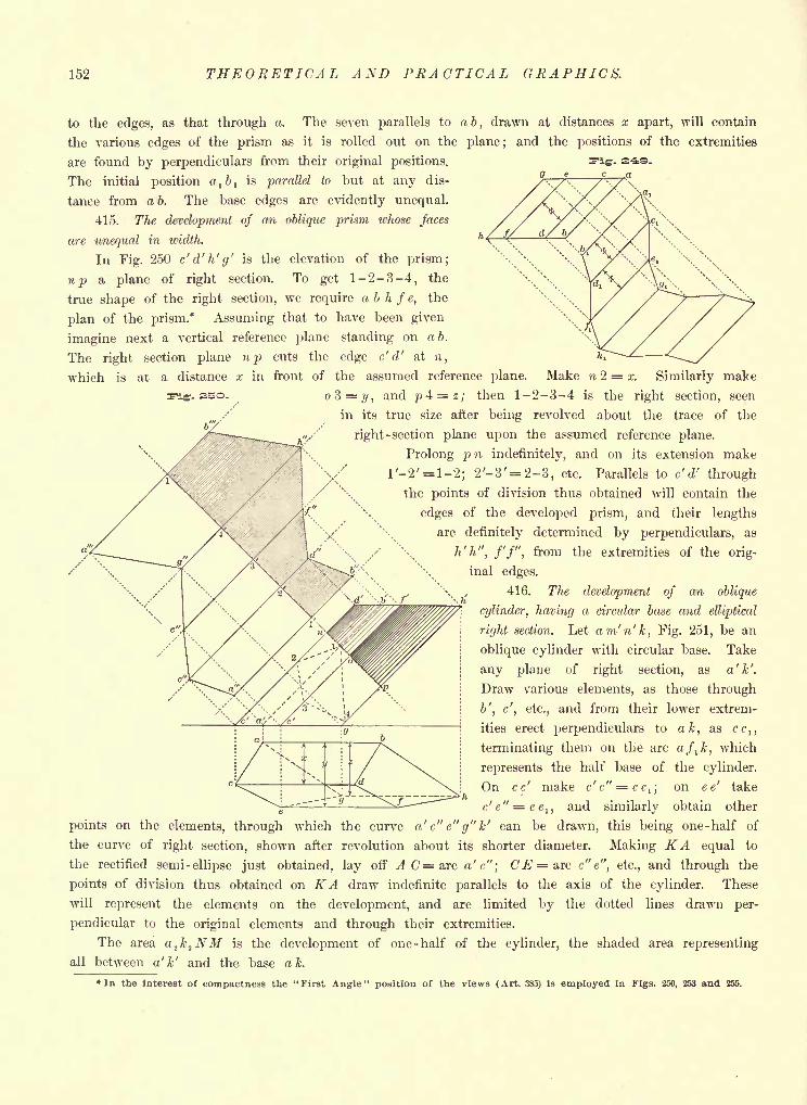
152 THEORETICAL AXD PRACTICAL GRAPHICS.
FLg. SSO.
to the edges, as that through a. The seven parallels to ab, drawn at distances x apart, will contain
the various edges of the prism as it is rolled out on the plane; and the positions of the extremities
are found by perpendiculars from their original positions.
The initial position a,b
,is parallel to but at any dis-
tance from ab. The base edges are evidently unequal.
415. The development of an oblique prism whose faces
are unequal in width.
In Fig. 250 c' d' h' g' is the elevation of the prism;
np a plane of right section. To get 1-2-3-4, the
true shape of the right section, we require a b h f e, the
plan of the prism.* Assuming that to have been given
imagine next a vertical reference plane standing on a 6.
The right section plane np cuts the edge c' d' at n,
which is at a distance x in front of the assumed reference plane. Make n 2 = x. Similarly make
1 =2/, and j?4
= z; then 1-2-3-4 is the right section, seen
in its true size after being revolved about the trace of the
right -section plane upon the assumed reference plane.
Prolong p n indefinitely, and on its extension make
l'-2'=l-2; 2'-3'= 2-3, etc. Parallels to c' d' through
the points of division thus obtained will contain the
edges of the developed prism, and their lengths
are definitely determined by perpendiculars, as
\ / \ h' h", f'f", from the extremities of the orig-
inal edges.
416. The development of an oblique
cylinder, having a circular base and elliptical
right section. Let am'n'k, Fig. 251, be an
oblique cylinder with circular base. Take
any plane of right section, as a'k'.
Draw various elements, as those through
b', c', etc., and from their lower extrem-
ities erect perpendiculars to ak, as cc,,
terminating them on the arc aft k, which
represents the half base of the cylinder.
On cc' make c'c" = cc1 ;
on e e' take
e'e" = ee1 ,
and similarly obtain other
points on the elements, through which the curve a' c" e" g" k' can be drawn, this being one -half of
the curve of right section, shown after revolution about its shorter diameter. Making KA equal to
the rectified semi-ellipse just obtained, lay off A C= arc a'c"; C.E=arc c"e", etc., and through the
points of division thus obtained on KA draw indefinite parallels to the axis of the cylinder. These
will represent the elements on the development, and are limited by the dotted lines drawn per-
pendicular to the original elements and through their extremities.
The area a1k
1NM is the development of one -half of the cylinder, the shaded area representing
all between a'k' and the base ak.
In the interest of compactness the "First Angle" position of the views (Art. 385) is employed in Figs. 250, 253 and 255.
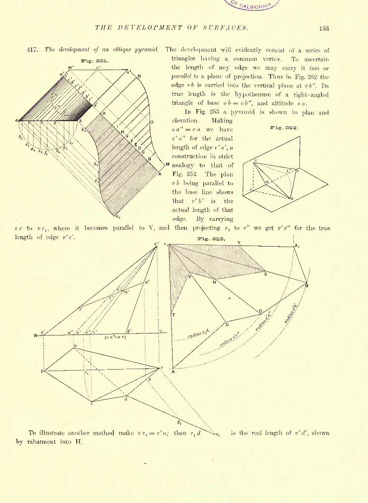
THE DE VELOPMENT F ft URFACE S. 153
417.
vc to
length
The development of an oblique pyramid. The development will evidently consist of a series of
triangles having a common vertex. To ascertain
the length of any edge we may carry it into or
parallel to a plane of projection. Thus in Fig. 252 the
edge vb is carried into the vertical plane at vb". Its
true length is the hypothenuse of a right-angled
triangle of base ob = ob", and altitude v o .
In Fig. 253 a pyramid is shown in plan and
elevation. Makingo a" = v a we have
v' a" for the actual
length of edge v' a', a
construction in strict
>Manalogy to that of
Fig. 252. The plan
v b being parallel to
the base line shows
that v'1>' is the
actual length of that
edge. By carrying
vct ,
where it becomes parallel to V, and then projecting cl
to c" we get v' c" for the true
of edge v'c'. FIS. 253.
A,
To illustrate another method make v v,
= o'
o ; then v,d
by rabatment into H.
u, is the real length of v'd', shown
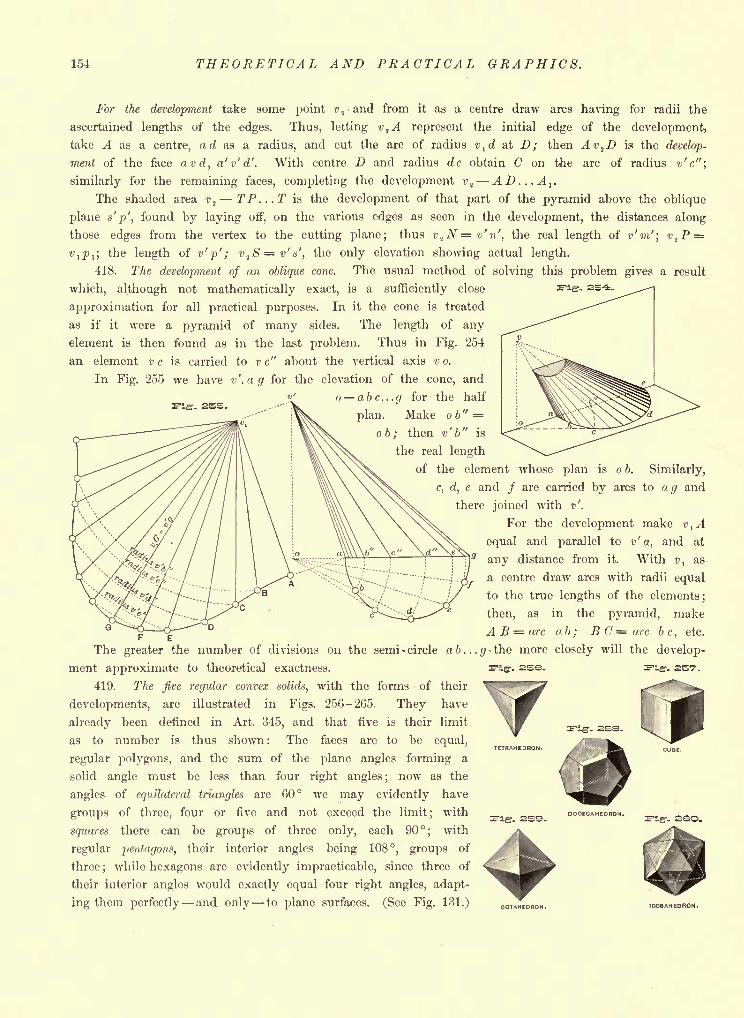
154 THEORETICAL AND PRACTICAL GRAPHICS.
For the development take some point vtand from it as a centre draw arcs having for radii the
ascertained lengths of the edges. Thus, letting v2A represent the initial edge of the development,
take A as a centre, ad as a radius, and cut the arc of radius vtd at D; then Av,D is the develop-
ment of the face avd, a'v'd'. With centre D and radius dc obtain C on the arc of radius v'c";
similarly for the remaining faces, completing the development vt
- AD...A1
.
The shaded area v 2 TP...T is the development of that part of the pyramid above the oblique
plane s'p', found by laying off, on the various edges as seen in the development, the distances along
those edges from the vertex to the cutting plane; thus v^N=v'n', the real length of v'm'; vtP =
vl p l ;
the length of v' p' ; v^S=v's', the only elevation showing actual length.
418. The development of an oblique cone. The usual method of solving this problem gives a result
which, although not mathematically exact, is a sufficiently close
approximation for all practical purposes. In it the cone is treated
as if it were a pyramid of many sides. The length of any
element is then found as in the last problem. Thus in Fig. 254
an element v c is carried to v c" about the vertical axis v o.
In Fig. 255 we have v'.ag for the elevation of the cone, and'
o abc...y for the half
plan. Make o b" =
ob; then v' b" is
the real length
of the element whose plan is o b. Similarly,
c, d, e and / are carried by arcs to ag and
there joined with v'.
For the development make vlA
equal and parallel to v' a, and at
any distance from it. With vl
as
a centre draw arcs with radii equal
to the true lengths of the elements;
then, as in the pyramid, make
A arc a b ; B C = arc b c,
etc.
The greater the number of divisions 011 the semi - circle a b...g the more closely will the develop-
ment approximate to theoretical exactness.
419. The five regular convex solids, with the forms of their
developments, are illustrated in Figs. 256-265. They have
already been defined in Art. 345, and that five is their limit
as to number is thus shown: The faces are to be equal,
regular polygons, and the sum of the plane angles forming a
solid angle must be less than four right angles ;now as the
angles of equilateral triangles are 60 we may evidently have
groups of three, four or five and not exceed the limit; with
squares there can be groups of three only, each 90; with
regular pentagons, their interior angles being 108, groups of
three;while hexagons are evidently impracticable, since three of
their interior angles would exactly equal four right angles, adapt-
ing them perfectly and only to plane surfaces. (See Fig. 131.)
f- 2S-7.
OCTAHEDRON. ICOSAHEORON.
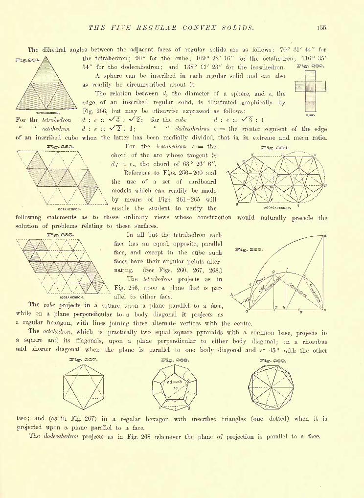
THE FIVE REGULAR CONVEX SOLIDS. 155
The dihedral angles between the adjacent faces of regular solids are as follows: 70 31' 44" for
the tetrahedron; 90 for the cube; 109 28' 16" for the octahedron; 116 35'
54" for the dodecahedron; and 138 11' 23" for the icosahedron.
A sphere can be inscribed in each regular solid and can also
as readily be circumscribed about it.
The relation between d, the diameter of a sphere, and e, the
edge of an inscribed regular solid, is illustrated graphically by
Fig. 266, but may be otherwise expressed as follows :
d : e : : v' 3 : v' 2;
for the cube d : e : : V 3 : 1
" "octahedron d : e '.'. ^2 : 1;
" "dodecahedron e = the greater segment of the edge
of an inscribed cube when the latter has been medially divided, that is, in extreme and mean ratio.
TETRAHEDRON.
For the tetrahedron
. 2S3.
OCTAHEDRON.
For the icosahedron e = the
chord of the arc whose tangent is
d; L e., the chord of 63 26' 6".
Reference to Figs. 256-260 and
the use of a set of cardboard
models which can readily be made
\ by means of Figs. 261-265 will
enable the student to verify the DODECAHEDRON.
following statements as to those ordinary views whose construction would naturally precede the
solution of problems relating to these surfaces.
.ass. In all but the tetrahedron each
face has an equal, opposite, parallel
face, and except in the cube such
faces have their angular points alter-
nating. (See Figs. 260, 267, 268.)
The tetrahedron projects as in
Fig. 256, upon a plane that is par-
allel to either face.
The cube projects in a square upon a plane parallel to a face,
while on a plane perpendicular to a body diagonal it projects as
a regular hexagon, with lines joining three alternate vertices with the centre.
The octahedron, which is practically two equal square pyramids with a common base, projects in
a square and its diagonals, upon a plane perpendicular to either body diagonal; in a rhombusand shorter diagonal when the plane is parallel to one body diagonal and at 45 with the other
iFiir- se7.
ICOSAHEDRON.
two; and (as in Fig. 267) in a regular hexagon with inscribed triangles (one dotted) when it is
projected upon a plane parallel to a face.
The dodecahedron projects as in Fig. 268 whenever the plane of projection is parallel to a face.
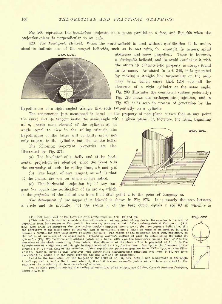
156 THEORETICAL AND PRACTICAL GRAPHICS.
- 37O-
Fig. 260 represents the icosahedron projected on a plane parallel to a face, and Fig. 269 when the
projection -plane is perpendicular to an axis.
420. The Developable Helicoid. When the word helicoid is used without qualification it is under-
stood to indicate one of the warped helicoids, such as is met with, for example, in screws, spiral
staircases and screw propellers. There is, however,
a developable helicoid, and to avoid confusing it with
the others its characteristic property is always found
in its name. As stated in Art. 346, it is generated
by moving a straight line tangentially on the ordi-
nary helix, which curve (Art. 120) cuts all the
elements of a right cylinder at the same angle.
Fig. 209 illustrates the completed surface pictorially;
Fig. 270 shows one orthographic projection, and in
Fig. 271 it is seen in process of generation by the
hypothenuse of a right-angled triangle that rolls tangentially on a cylinder.
The construction just mentioned is based on the property of non-plane curves that at any point
the curve and its tangent make the same angle with a given plane; if, therefore, the helix, beginning
at a, crosses each element of the cylinder at an
angle equal to obp in the rolling triangle, the
hypothenuse of the latter will evidently move not
only tangent to the cylinder, but also to the helix.
The following important properties are also
illustrated by Fig. 271:
(a) The involute* of a helix and of its hori-
zontal projection are identical, since the point b is
the extremity of both the rolling lines, 06 and pb.
(b) The length of any tangent, as mb, is that
of the helical arc m a on which it has rolled.
(c) The horizontal projection b q of any tan-
gent 6 m equals the rectification of an arc a q which
is the projection of the helical arc from the initial point a to the point of tangency m.
The development of one nappe of a helicoid is shown in Fig. 273. It is merely the area between
a circle and its involute; but the radius p, of the base circle, equals r sec2
0,t in which r is
-. S171..
* For full treatment of the Involute of a circle refer to Arts. 186 and 187.
t This relation is due to considerations of curvature. At any point of any curve Its curvature is its rate of
departure from its tangent at that point. Its radius of curvature is that of the osculatory circle at that point. (Art.
380.) Now from the nature of the two uniform motions imposed upon a point that generates a helix (Art. 120)
the curvature of the latter must be uniform; and if developed upon a plane by means of its curvature it mustbecome a circle the only plane curve of uniform curvature. The radius of the developed helix will, obviously, bethe radius of curvature of the space helix. Following Warren's method of proof in establishing its value let
o, 6 and c (Fig. 272) be three equi-distant points on a helix, with 6 on the foremost element; then a' c' is the
elevation of the circle containing these points. One diameter of the circle a'b'c' is projected at 6'. It is the
hypothenuse of a right-angled triangle having the chord be, b'c', for its base. Let If be the diameter of the
circle a'b'c'; 2r= i>d, that of the cylinder. Using capitals for points in space we have JTC* =2pX*e; also 6~c*
2rXbe; whence, dividing like members and substituting trigonometric functions (see note p. 31), we have
P = rsec 2p, in which is the angle between the line BC and its projection.
Let 6 be the inclination of the tangent to the helix at b'. If, now, both A and C approach B, the angle
3 will approach 9 as its limit; and when A, B and C become consecutive points we will have p = rsec 2 fl = the
radius of the osculatory circle = the radius of curvature.
For another proof, involving the radius of curvature of an ellipse, see Olivier, Cours de Otomttrie Descriptive,
Third Ed., p. 197.
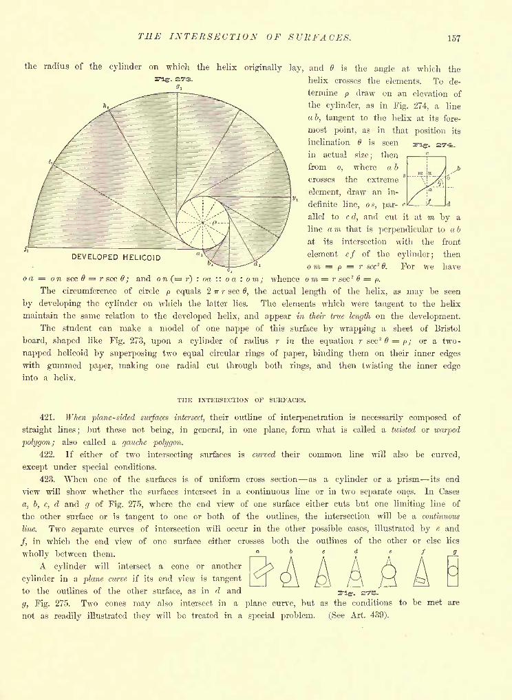
THE INTERSECTION OF SURFACES. 157
the radius of the cylinder on which the helix originally lay, and 6 is the angle at which the
helix crosses the elements. To de-
termine p draw on o.n elevation of
the cylinder, as in Fig. 274, a line
ab, tangent to the helix at its fore-
most point, as in that position its
inclination 6 is seen
in actual size; then
from o, where a 6
crosses the extreme
element, draw an in-
definite line, os, par-
allel to c d, and cut it at m by a
line a in that is perpendicular to a b
at its intersection with the front
element ef of the cylinder; then
o m = p = ? sec26. For we have
oa = on sec = r sec ; and on (= r) : oa :: o a : om; whence om = r sec2 6 = p.
The circumference of circle p equals ITT r sec 6, the actual length of the helix, as may be seen
by developing the cylinder on which the latter lies. The elements which were tangent to the helix
maintain the same relation to the developed helix, and appear in their true length on the development.
The student can make a model of one nappe of this surface by wrapping a sheet of Bristol
board, shaped like Fig. 273, upon a cylinder of radius r in the equation r sec2 6 = p; or a two-
napped helicoid by superposing two equal circular rings of paper, binding them on their inner edges
with gummed paper, making one radial cut through both rings, and then twisting the inner edge
into a helix.
DEVELOPED HELICOID
THE INTERSECTION OF SURFACES.
421. When plane-sided surfaces intersect, their outline of interpenetration is necessarily composed of
straight lines; but these not being, in general, in one plane, form what is called a tivisted or warped
polygon; also called a gauche polygon.
422. If either of two intersecting surfaces is curved their common line will also be curved,
except under special conditions.
423. When one of the surfaces is of uniform cross section as a cylinder or a prism its end
view will show whether the surfaces intersect in a continuous line or in two separate ones. In Cases
a, b, c, d and g of Fig. 275, where the end view of one surface either cuts but one limiting line of
the other surface or is tangent to one or both of the outlines, the intersection will be a continuous
line. Two separate curves of intersection will occur in the other possible cases, illustrated by e and
/, in which the end view of one surface either crosses both the outlines of the other or else lies
wholly between them. a b c d e f -8-
A cylinder will intersect a cone or another
cylinder in a plane curve if its end view is tangent
to the outlines of the other surface, as in d and Fig-. STB.
g, Fig. 275. Two cones may also intersect in a plane curve, but as the conditions to be met are
not as readily illustrated they will be treated in a special problem. (See Art. 439).
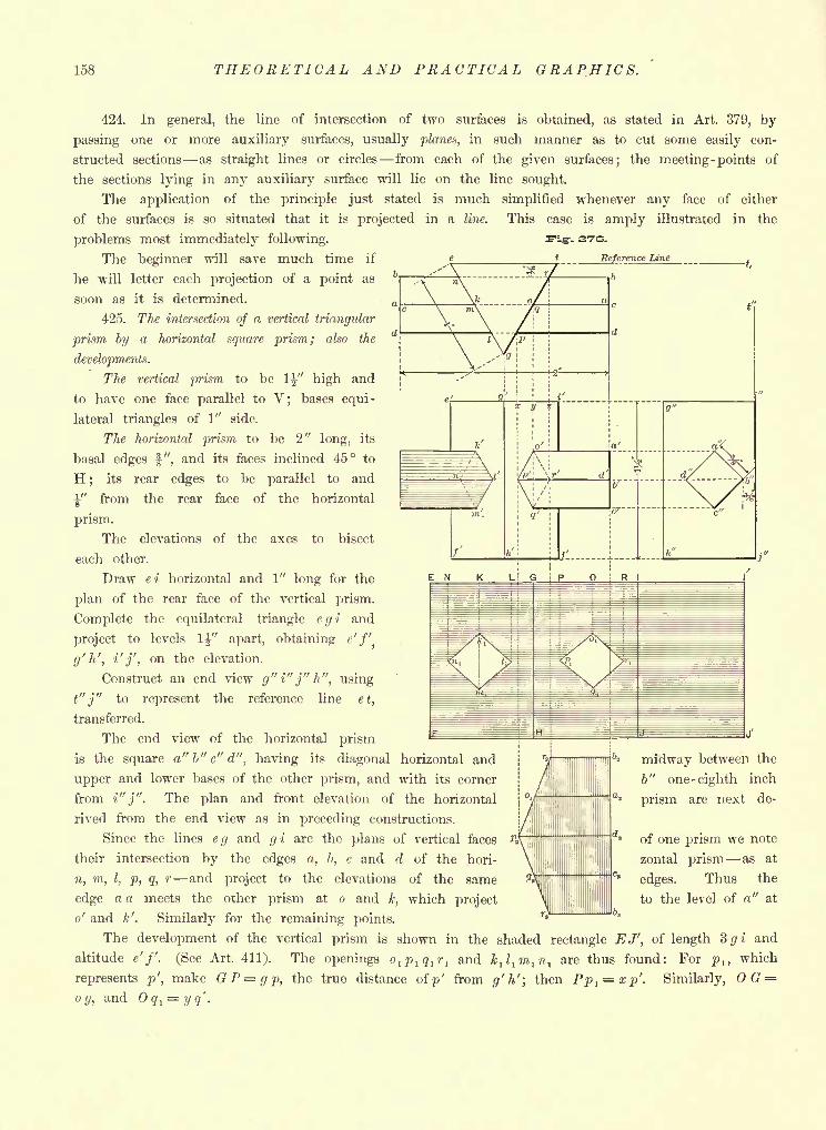
158 THEORETICAL AND PRACTICAL GRAPHICS.
424. In general, the line of intersection of two surfaces is obtained, as stated in Art. 379, by
passing one or more auxiliary surfaces, usually planes, in such manner as to cut some easily con-
structed sections as straight lines or circles from each of the given surfaces; the meeting -points of
the sections lying in any auxiliary surface will lie on the line sought.
The application of the principle just stated is much simplified whenever any face of either
of the surfaces is so situated that it is projected in a line. This case is amply illustrated in the
problems most immediately following. Fig-, svs.
The beginner will save much time if L_ Reference tine
he will letter each projection of a point as ^
soon as it is determined.
425. The intersection of a vertical triangular
prism by a horizontal square prism; also the
developments.
The vertical prism to be1-J-" high and
to have one face parallel to V; bases equi-
lateral triangles of 1" side.
The horizontal prism to be 2" long, its
basal edges f", and its faces inclined 45 to
H;
its rear edges to be parallel to and
y from the rear face of the horizontal
prism.
The elevations of the axes to bisect
each other.
Draw ei horizontal and 1" long for the
plan of the rear face of the vertical prism.
Complete the equilateral triangle egi and
project to levels 1" apart, obtaining <'/'
g'h', i'j' on the elevation.
Construct an end view g" i" j"
t" j" to represent the reference
transferred.
The end
h, using
line et,
view of the horizontal prism
is the square a"b"c"d", having its diagonal horizontal and
upper and lower bases of the other prism, and with its corner
from i"j". The plan and front elevation of the horizontal
rived from the end view as in preceding constructions.
Since the lines eg and gi are the plans of vertical faces
their intersection by the edges a, b, c and d of the hori-
n, m, I, p, q, r and project to the elevations of the same
edge a a meets the other prism at o and k, which project
o' and k'. Similarly for the remaining points.
The development of the vertical prism is shown in the shaded rectangle EJ', of length Sgi and
altitude e' f. (See Art. 411). The openings ol p 1 q 1
r1and k
ll
lm
1n
lare thus found: For p lt which
represents p', make GP=gp, the true distance ofp' from g'h'; then Pp 1= xp'. Similarly, OG =
og, and Oq, = yq.
midway between the
b" one -eighth inch
prism are next de-
of one prism we note
zontal prism as at
edges. Thus the
to the level of a" at
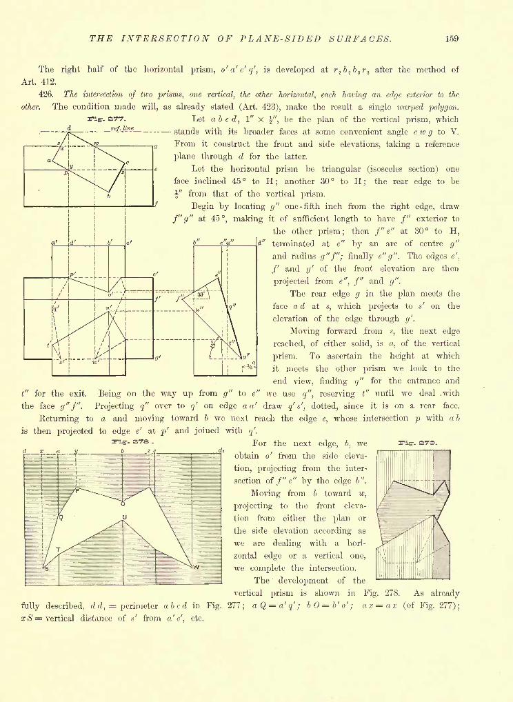
THE INTERSECTION OF PLANE-SIDED SURFACES. 159
The right half of the horizontal prism, o'a'c'q', is developed at r2b
2b
sr
3after the method of
Art. 412.
426. The intersection of two prisms, one vertical, the other horizontal, each having an edge exterior to the
other. The condition made will, as already stated (Art. 423), make the result a single warped polygon.
-. s,T7. Let abed, 1" x %", be the plan of the vertical prism, which
stands with its broader faces at some convenient angle c w g to V.
From it construct the front and side elevations, taking a reference
plane through d for the latter.
Let the horizontal prism be triangular (isosceles section) one
face inclined 45 to H; another 30 to H; the rear edge to be
from that of the vertical prism.
Begin by locating g" one -fifth inch from the right edge, draw
f" g" at 45, making it of sufficient length to have /" exterior to
the other prism; then f'e" at 30 to H,
terminated at e" by an arc of centre g"
and radius g"f"; finally e" g". The edges e',
/' and g' of the front elevation are then
projected from e", f" and g".
The rear edge g in the plan meets the
face d at s, which projects to s' on the
elevation of the edge through g'.
Moving forward from n, the next edge
reached, of either solid, is,of the vertical
prism. To ascertain the height at which
it meets the other prism we look to the
end view, finding q" for the entrance and
t" for the exit. Being on the way up from g" to e" we use q", reserving t" until we deal .with
the face </"/" Projecting q" over to q' on edge a a' draw q' s', dotted, since it is on a rear face.
Eeturning to a and moving toward b we next reach the edge e, whose intersection p with a b
is then projected to edge e' at p' and joined with q'.
For the next edge, b, we
obtain o' from the side eleva-
tion, projecting from the inter-
section of f" e" by the edge b".
Moving from b toward w,
projecting to the front eleva-
tion from either the plan or
the side elevation according as
we are dealing with a hori-
zontal edge or a vertical one,
we complete the intersection.
The development of the
vertical prism is shown in Fig. 278. As already
fully described, dd, = perimeter abed in Fig. 277; aQ=a'q'; b = b' o' ; ax=ax (of Fig. 277);
x S = vertical distance of *' from a'c'. etc.
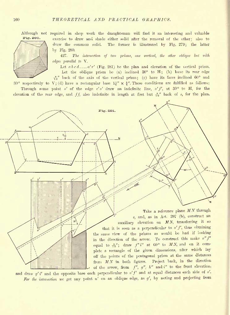
160 THEORETICAL AND PRACTICAL GRAPHICS.
Although not required in shop work the draughtsman will find it an interesting and valuable
sso - exercise to draw and shade either solid after the removal of the other; also to
draw the common solid. The former is illustrated by Fig. 279;
the latter
by Fig. 280.
427. The intersection of two prisms, one vertical, the other oblique but with
edges parallel to V.
Let abcd....a'r' (Fig. 281) be the plan and elevation of the vertical prism.
Let the oblique prism be (a) inclined 30 to H; (b) have its rear edge
fa" back of the axis of the vertical prism; (c) have its faces inclined 60 and
30 respectively to V; (d) have a rectangular base 1|" X f". These conditions are fulfilled as follows:
Through some point o' of the edge e' o' draw an indefinite line, o'f, at 30 to H, for the
elevation of the rear edge, and //, also indefinite in length at first but $$" back of s, for the plan.
ig-. 2S1-
Nl
Take a reference plane MN through
s, and, as in Art. 397 (b), construct an
auxiliary elevation on MN, transferring it so
that it is seen as a perpendicular to o'f, thus obtaining
the same view of the prisms as would be had if looking
in the direction of the arrow. To construct this make o" f"
equal to TV; draw f"i" at 60 to MN, and on it com-
plete a rectangle of the given dimensions, after which lay
off the points of the pentagonal prism at the same distances
from MN in both figures. Project back, in the direction
of the arrow, from /", g",- h" and i" to the front elevation,
and draw g' i' and the opposite base each perpendicular to o'/' and at equal distances each side of o'.
For the intersection we get any point n' on an oblique edge, as g', by noting and projecting from
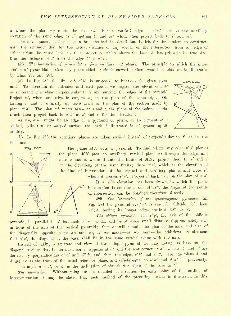
THE INTERSECTION OF PLANE-SIDED SURFACES. 161
n where the plan gg meets the face c d. For a vertical edge as c' m' look to the auxiliary
elevation of the same edge, as c", getting I" and 771" which then project back to I' and m'.
The development need not again be described in detail but is left for the student to construct!
with the reminder that for the actual distance of any corner of the intersection from an edge of
either prism he must look to that projection which shows the base of that prism in its true size:
thus the distance of I' from the edge h' is h"l".
428. The intersection of pyramidal surfaces by lines and planes. The principle on which the inter-
section of pyramidal surfaces by plane -sided or single curved surfaces would be obtained is illustrated
by Figs. 282 and 283.
(a) In Fig. 282 the line a b, a' b', is supposed to intersect the given pyra-
mid. To ascertain its entrance and exit points we regard the elevation a' b'
as representing a plane perpendicular to V and cutting the edges of the pyramid.
Project m', where one edge is cut, to771,
on the plan of the same edge. Ob-
taining n and o similarly we have m n o as the plan of the section made by
plane a'b'. The plan ab meets mno at s andt,
the plans of the points sought,
which then project back to a'b' at s' and t' for the elevations.
As a b, a'b', might be an edge of a pyramid or prism, or an element of a
conical, cylindrical or warped surface, the method illustrated is of general appli-
cability.
(b) In Fig. 283 the auxiliary planes are taken vertical, instead of perpendicular to V as in the
last case.
The plane MN cuts a pyramid. To find where any edge v' o' pierces
the plane MN pass an auxiliary vertical plane xz through the edge, and
note x and z, where it cuts the limits of MN; project these to x' and z'
on the elevations of the same limits; draw x'z', which is the elevation of
the line of intersection of the original and auxiliary planes, and note s',
where it crosses v' o'. Project s' back to s on the plan of v'o'.
If a side elevation has been drawn, in which the plane
in question is seen as a line M" N", the height of the points
of intersection can be obtained therefrom directly.
429. The intersection of two quadrangular pyramids. In
Fig. 284 the pyramid v.efgh is vertical; altitude v' z' ; base
efgh, having its longer edges inclined 30 to V.
The oblique pyramid. Let s'y', the axis of the oblique
pyramid, be parallel to V but inclined to H, and be at some small distance (approximately v k)
in front of the axis of the vertical pyramid; then sc will contain the plan of the axis, and also of
the diagonally opposite edges sa and s c,if we make as we may the additional requirement
that a'c', the diagonal of the base, shall lie in the same vertical plane with the axis.
Instead of taking a separate end view of the oblique pyramid we may rotate its base on the
diagonal a'c' so that its foremost corner appears at b" and the rear corner at d", whence b' and d' are
derived by perpendiculars b" b' and d" d', and then the edges s' b' and s' d'. For the plans b and
d use sc as the trace of the usual reference plane, and offsets equal to b' b" and d'd", as previously.
The angle a' c' d', or<f>,
is the inclination of the shorter edges of the base to V.
The intersection. Without going into a detailed construction for each point of the outline of
interpenetration it may be stated that each method of the preceding article is illustrated in this
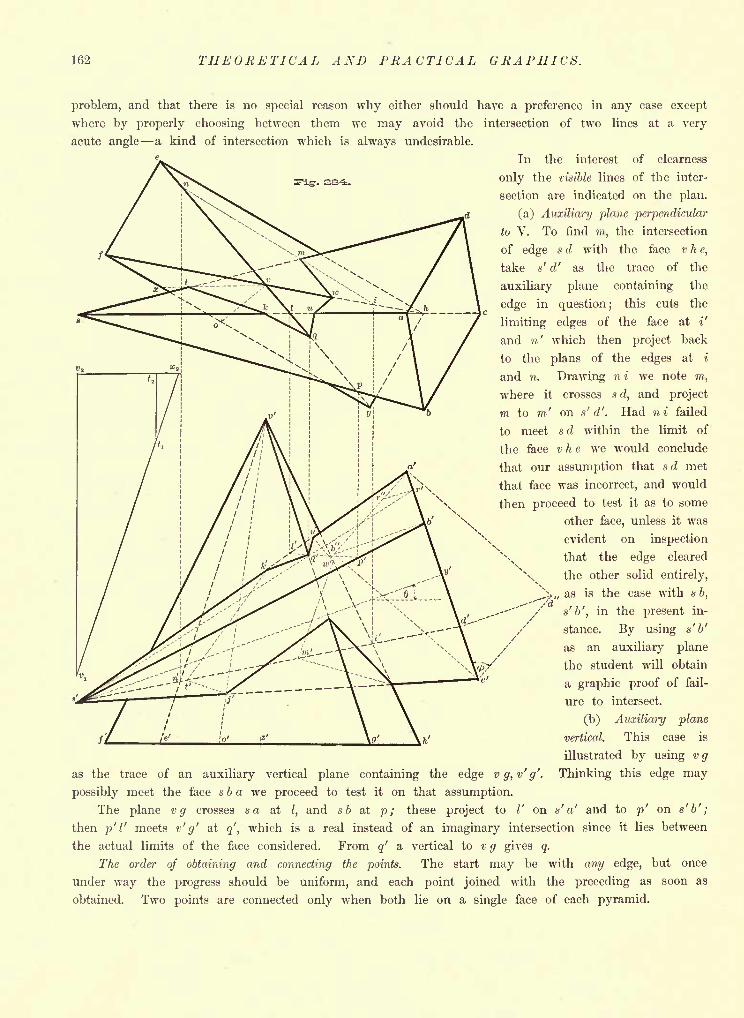
162 THEORETICAL AND PRACTICAL GRAPHICS.
problem, and that there is no special reason why either should have a preference in any case except
where by properly choosing between them we may avoid the intersection of two lines at a very
acute angle a kind of intersection which is always undesirable.
In the interest of clearness
only the visible lines of the inter-
section are indicated on the plan,
(a) Auxiliary plane perpendicular
to V. To find m, the intersection
of edge s d with the face v he,
take s' d' as the trace of the
auxiliary plane containing the
edge in question; this cuts the
limiting edges of the face at i'
and n' which then project back
to the plans of the edges at i
and n. Drawing ni we note m,
where it crosses s d, and project
m to m' on s' d'. Had ni failed
to meet sd within the limit of
the face v h e we would conclude
that our assumption that sd met
that face was incorrect, and would
then proceed to test it as to some
other face, unless it was
evident on inspection
that the edge cleared
\ the other solid entirely,
^>,,as is the case with sb,
'
/ s'b', in the present in-
stance. By using s'b'
as an auxiliary plane
the student will obtain
a graphic proof of fail-
ure to intersect.
(b) Auxiliary plane
vertical. This case is
illustrated by using vg
as the trace of an auxiliary vertical plane containing the edge vg,v'g'. Thinking this edge may
possibly meet the face s b a we proceed to test it on that assumption.
The plane vg crosses sa atI,
and sb at p; these project to I' on s' a' and to p' on s'b';
then p'V meets v' g' at q', which is a real instead of an imaginary intersection since it lies between
the actual limits of the face considered. From q' a vertical to vg gives q.
The order of obtaining and connecting the points. The start may be with any edge, but once
under way the progress should be uniform, and each point joined with the preceding as soon as
obtained. Two points are connected only when both lie on a single face of each pyramid.
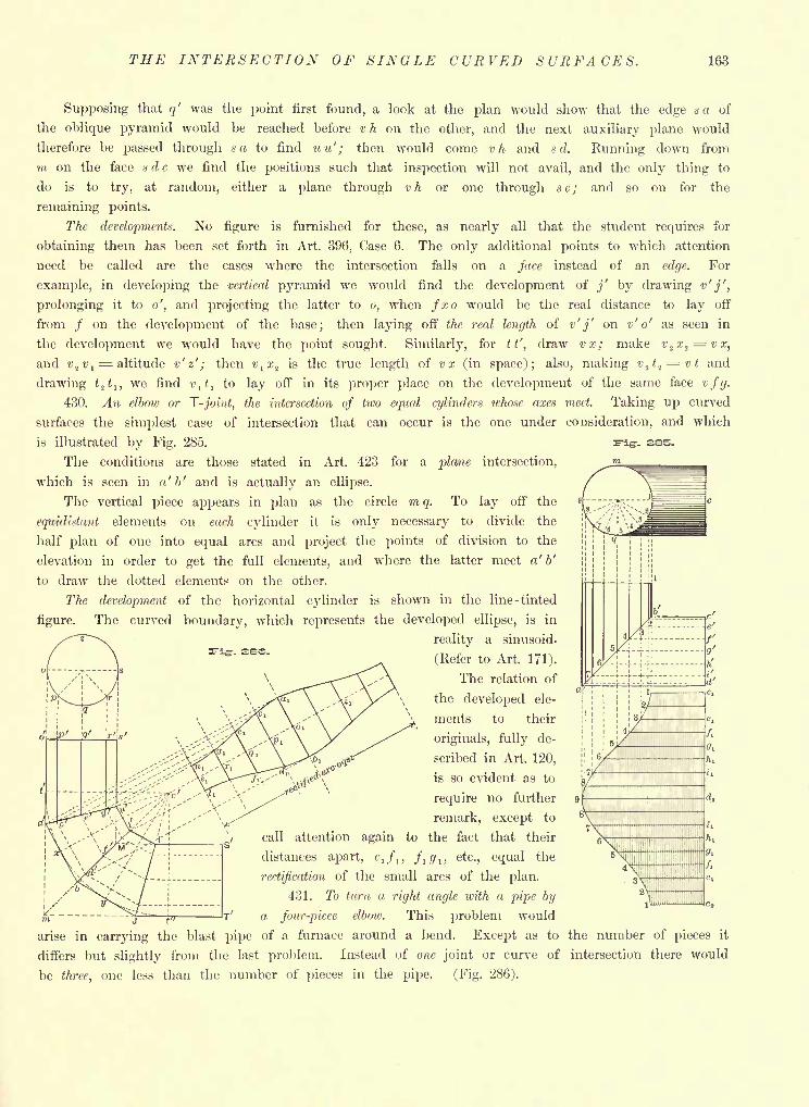
THE INTERSECTION OF SINGLE CURVED SURFACES. 163
- S.S5-
Supposing that q' was the point first found, a look at the plan would show that the edge sa of
the oblique pyramid would be reached before v h on the other, and the next auxiliary plane would
therefore be passed through sa to find u u' ; then would come vh and s d. Running down from
m on the face s d c we find the positions such that inspection will not avail, and the only thing to
do is to try, at random, either a plane through v h or one through s c ; and so on for the
remaining points.
The developments. No figure is furnished for these, as nearly all that the student requires for
obtaining them has been set forth in Art. 396, Case 6. The only additional points to which attention
need be called are the cases where the intersection falls on a face instead of an edge. For
example, in developing the vertical pyramid we would find the development of j' by drawing v' j',
prolonging it to o', and projecting the latter to o, when fxo would be the real distance to lay off
from / on the development of the base; then laying off the real length of v' j' on v' o' as seen in
the development we would have the point sought. Similarly, for tt', draw vx; make v,zx
1 ^=vx,
and v2v
,= altitude v' e' ; then v
lx
1is the true length of vx (in space); also, making v.
ft.f=^vt and
drawing t^t t ,we find v
lt
lto lay off in its proper place on the development of the same face vfg.
430. An elbow or T-joint, the intersection of two equal cylinders whose axes meet. Taking up curved
surfaces the simplest case of intersection that can occur is the one under consideration, and which
is illustrated by Fig. 285.
The conditions are those stated in Art. 423 for a plane intersection,
which is seen in a' b' and is actually an ellipse.
The vertical piece appears in plan as the circle mq. To lay off the
equidistant elements on each cylinder it is only necessary to divide the
half plan of one into equal arcs and project the points of division to the
elevation in order to get the full elements, and where the latter meet a' b'
to draw the dotted elements on the other.
The development of the horizontal cylinder is shown in the line -tinted
figure. The curved boundary, which represents the developed ellipse, is in
reality a sinusoid-
(Refer to Art. 171).
The relation of
the developed ele-
ments to their
originals, fully de-
scribed in Art. 120,
, .,fi,e^\ is so evident as to" \
require no further
remark, except to
call attention again to the fact that their
distances apart, ',/,, ft g t , etc., equal the
rectification of the small arcs of the plan.
431. To turn a right angle loith a pipe by
a four-piece elbow. This problem would
arise in carrying the blast pipe of a furnace around a bend. Except as to the number of pieces it
differs but slightly from the last problem. Instead of one joint or curve of intersection there would
be three, one less than the number of pieces in the pipe. (Fig. 286).
T^ig-. ESS.
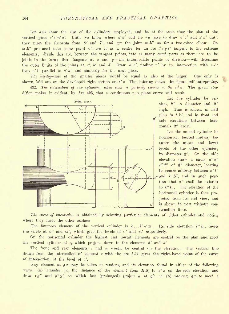
164 THEORETICAL AND PRACTICAL GRAPHICS.
Let o q a show the size of the cylinders employed, and be at the same time the plan of the
vertical piece o's'n'a'. Until we know where a' n' will lie we have to draw o' a' and s' n' until
they meet the elements from S' and T', and get the joint m M' as for a two-piece elbow. On
m M' produced take some point v', use it as a centre for an arc t' x y t" tangent to the extreme
elements; divide this arc, between the tangent points, into as many equal parts as there are to be
joints in the turn; then tangents at x and y the intermediate points of division will determine
the outer limits of the joints at a', b' and J. Draw a'v', finding n' by its intersection with ss';
then n' I' parallel to a'b', and similarly for the next piece.
The developments of the smaller pieces would be equal, as also of the larger. One only is
shown, laid out on the developed right section on v' x. The lettering makes the figure self- interpreting.
432. The intersection of two cylinders, when each is partially exterior to the other. The given con-
dition makes it evident, by Art. 423, that a continuous non- plane curve will result.
Let one cylinder be ver-
.. tical. 2" in diameter and 2"n STE f "z n
high. This is shown in half
plan in h kI,and in front and
side elevations between hori-
zontals 2" apart.
Let the second cylinder be
horizontal; located midway be-
tween the upper and lower
levels of the other cylinder;
its diameter f". On the side
elevation draw a circle a" b"
c" d" of"
diameter, locating
its centre midway between k" I"
and &1-/V, and in such posi-
tion that a" shall be exterior
to k"kt
. The elevation of the
horizontal cylinder is then pro-
jected from its end view, and
is shown in part without con-
struction lines.
The curve of intersection is obtained by selecting particular elements of either cylinder and noting
where they meet the other surface.
The foremost element of the vertical cylinder is k...k'n'm'. Its side elevation, k" k 1} meets
the circle at n" and m", which give the levels of n' and m' respectively.
On the horizontal cylinder the highest and lowest elements are central on the plan and meet
the vertical cylinder at e, which projects down to the elements d' and b'.
The front and rear elements, c and a, would be central on the elevation. The vertical line
drawn from the intersection of element c with the arc hkl gives the right-hand point of the curve
of intersection, at the level of a'.
Any element as gx may be taken at random, and its elevation found in either of the following
ways: (a) Transfer gz, the distance of the element from MN, to s" x on the sid.e elevation, and
draw xg" and g"y', to which last (prolonged) project g at g'; or (b) prolong gx to meet a
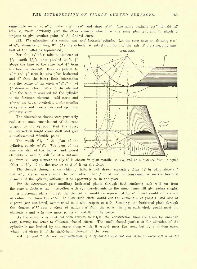
THE INTERSECTION OF SINGLE CURVED SURFACES. 165
-. see.
semi-circle on a c at g'" ; make a'y' = xg'" and draw y' g'. The same ordinate </'", if laid off
below a, would obviously give the other element which has the same plan gx, and to which g
projects to give another point of the desired curve.
433. The intersection of a vertical cone and horizontal cylinder. Let the cone have an altitude, w w',
of 4"; diameter of base, 3". (As the cylinder is entirely in front of the axis of the cone, only one-
half of the latter is represented.)
For the cylinder take a diameter of
"; length 3^"; axis parallel to V, |"
above the base of the cone, and \" from
the foremost element. Draw ns parallel to
p' r' and " from it; also g'm' horizontal
and f" from the base; their intersection
s is the centre of the circle a"d'c"m', of
$" diameter, which bears to the element
p' r' the relation assigned for the cylinder
to the foremost element; said circle and
p'ww' are thus, practically, a side elevation
of cylinder and cone, superposed upon the
ordinary view.
The dimensions chosen were purposely
such as to make one element of the cone
tangent to the cylinder, that the curve
of intersection might cross itself and give
a mathematical " dbuble point."
The width d b, of the plan of the
cylinder, equals m'<7'. The plan of the
axis (as also of the highest and lowest
elements,' and <') will be at a distance
(/' from iv. Any element as x' y' h' is shown in plan parallel to pq, and at a distance from it equal
either to h' y' if on the rear or to h' x' if on the front.
The element through v, on which /' falls, is not drawn separately from bf in plan, since vfand m' g' are so nearly equal to each other; but / must not be considered as on the foremost
element of the cylinder, although it is apparently so in the plan.
For the intersection pass auxiliary horizontal planes through both surfaces;
each will cut from
the cone a circle, whose intersection with cylinder-elements in the same plane will give points sought.
A horizontal plane through the element a' would be represented by a'<>', and would cut a circle
of radius o'z' from the cone. In plan such circle would cut the element a at point 1, and also at
a point (not numbered) symmetrical to it with respect to w Q. Similarly, the horizontal plane through
the element x' h' cuts a circle of radius I' h' from the cone; in plan such circle would meet the
elements x and y in two more points (5 and 3) of the curve.
As the curve is symmetrical with respect to wQw', the construction lines are given for one -half
only, leaving the other to illustrate shaded effects. The small shaded portion of the elevation of the
cylinder is not limited by the curve along which it would meet the cone, but by a random curve
which just clears it of the right-hand element of the cone.
434. To find the diameter and inclination of a cylindrical pipe that will make an elbow with a conical
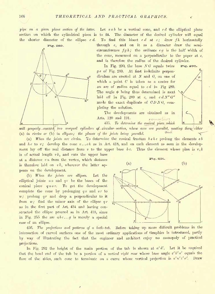
166 THEORETICAL AND PRACTICAL GRAPHICS.
pipe on a given plane section of the latter. Let v a b be a vertical cone, and c d the elliptical plane
section on which the cylindrical piece is to fit. The diameter of the desired cylinder will equal
the shorter diameter of the ellipse c d. To find this bisect cd at e; draw fh horizontally
through e, and on it as a diameter draw the semi-
circumference fg h; the ordinate eg is the half width of
the cone, measured on a perpendicular to the paper at e,
and is therefore the radius of the desired cylinder.
-. 2ss.
In Fig. 290, the base NG equals twice
g e of Fig. 289. At first indefinite perpen-
diculars are erected at N and G, on one of
which a point C is taken as a centre for
an arc of radius equal to c d in Fig 289.
The angle <f> being thus determined is next
laid off in Fig. 289 at c, and c d N" G"
made the exact duplicate of CDNG, com-
pleting the solution.
The developments are obtained as in
Arts. 120 and 191.
435. To determine the conical piece which
-. 2QO.
(a) (b)
will properly connect, two unequal cylinders of - circular section, whose axes are parallel, meeting then^ either
(a) in circles or (b) in ellipses; the planes of the joints being parallel. ^~~
(a) When the joints are circles. To determine the conical frustum b e h c prolong the elements e b
and he to v ; develop the cone v . . .eh as in Art. 418, and on each element as seen in the develop-
ment lay off the real distance from v to the upper base b c. Thus the element whose plan is vtk
is of actual length vktand cuts the upper base
at a distance v n from the vertex, which distance
is therefore laid on vktwherever the latter ap-
pears on the development.
(b) When the joints are ellipses. Let the
elliptical joints no and qr be the bases of the
conical piece q n o r. To get .the development
complete the cone by prolonging qn and or to
w ; prolong qr and drop a perpendicular to it
from w; find the minor axis of the ellipse qr
as in the first part of Art. 434 and having con-
.structed the ellipse proceed as in Art. 418, since
in Fig. 255 the arc abc...g is merely a special
case of an ellipse.
436. The projections and patterns of a bath-tub. Before taking up more difficult problems in the
intersection of curved surfaces one of the most ordinary applications of Graphics is introduced, partly
by way of illustrating the fact that the engineer and architect enjoy no monopoly of practical
projections.
In Fig. 292 the height of the main portion of the tub is shown at a'd'. Let it be required
that the head end of the tub be a portion of a vertical right cone whose base angle c'b'a' equals the
flare of the sides, such cone to terminate on a curve whose vertical projection is o'n'z'a'. Draw
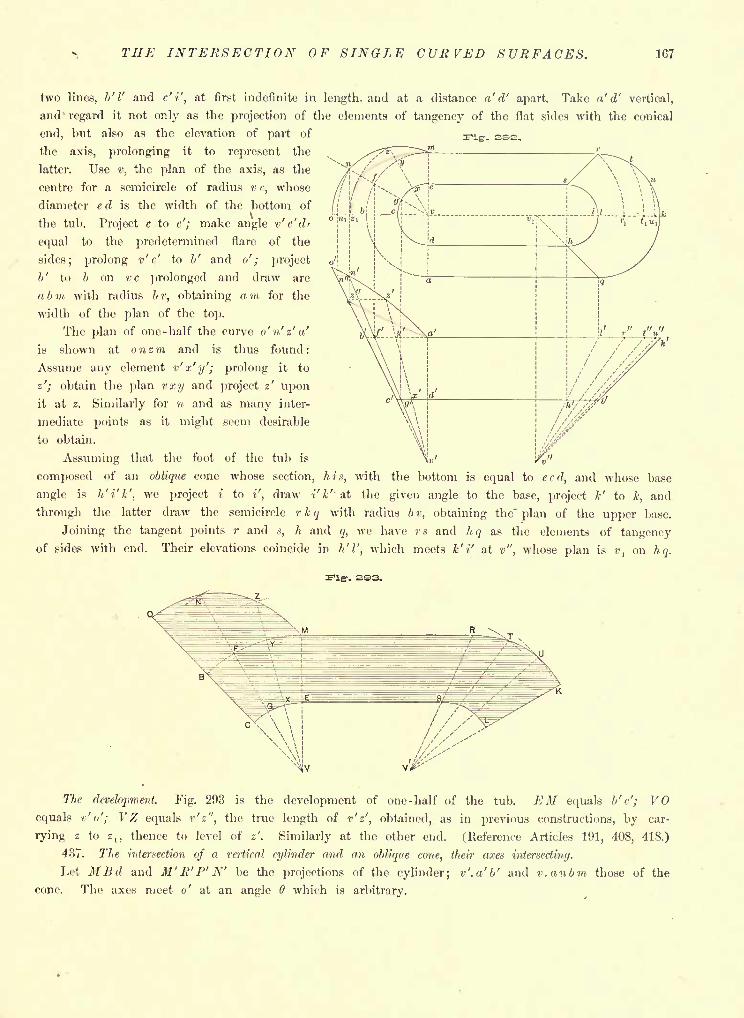
THE INTERSECTION OF SINGLE CURVED SURFACES. 167
two lines, b' I' and c'i', at first indefinite in length- and at a distance a' d' apart. Take a' d' vertical,
and regard it not only as the projection of the elements of tangency of the flat sides with the conical
end, but also as the elevation of part of
the axis, prolonging it to represent the
latter. Use v, the plan of the axis, as the
centre for a semicircle of radius v c, whose
diameter e d is the width of the bottom of
the tub. Project c to c'; make angle v' c' d'
equal to the predetermined flare of the
sides; prolong v' c' to b' and o' ; project
b' to b on vc prolonged and draw arc
a bin with radius br, obtaining am for the
width of the plan of the top.
The plan of one-half the curve o' n' z' a'
is shown at onzm and is thus found:
Assume any element v'x'y'; prolong it to
z'; obtain the plan vxy and project z' uponit at z. Similarly for n and as many inter-
mediate points as it might seem desirable
to obtain.
Assuming that the foot of the tub is
composed of an oblique cone whose section, his, with the bottom is equal to ecd, and whose base
angle is h'i'k', we project i to i', draw i' k'' at the given angle to the base, project k' to k, and
through the latter draw the semicircle rkq with radius br, obtaining the" plan of the upper base.
Joining the tangent points r ands, h and q, we have rs and hq as the elements of tangency
of sides with end. Their elevations coincide in h'l', which meets k' i' at v", whose plan is v, on hq.
-. 2S3.
The development. Fig. 293 is the development of one-half of the tub. EM equals b'c'; VOequals r'o'; VZ equals r'z", the true length of r'z', obtained, as in previous constructions, by car-
rying z to z,, thence to level of z'. Similarly at the other end. (Reference Articles 191, 408, 418.)
437. The intersection of a vertical cylinder and an oblique cone, their axes intersecting.
Let MBd and M'B'P'N' be the projections of the cylinder; v'.a'b' and v.anbm those of the
cone. The axes meet o' at an angle 6 which is arbitrary.
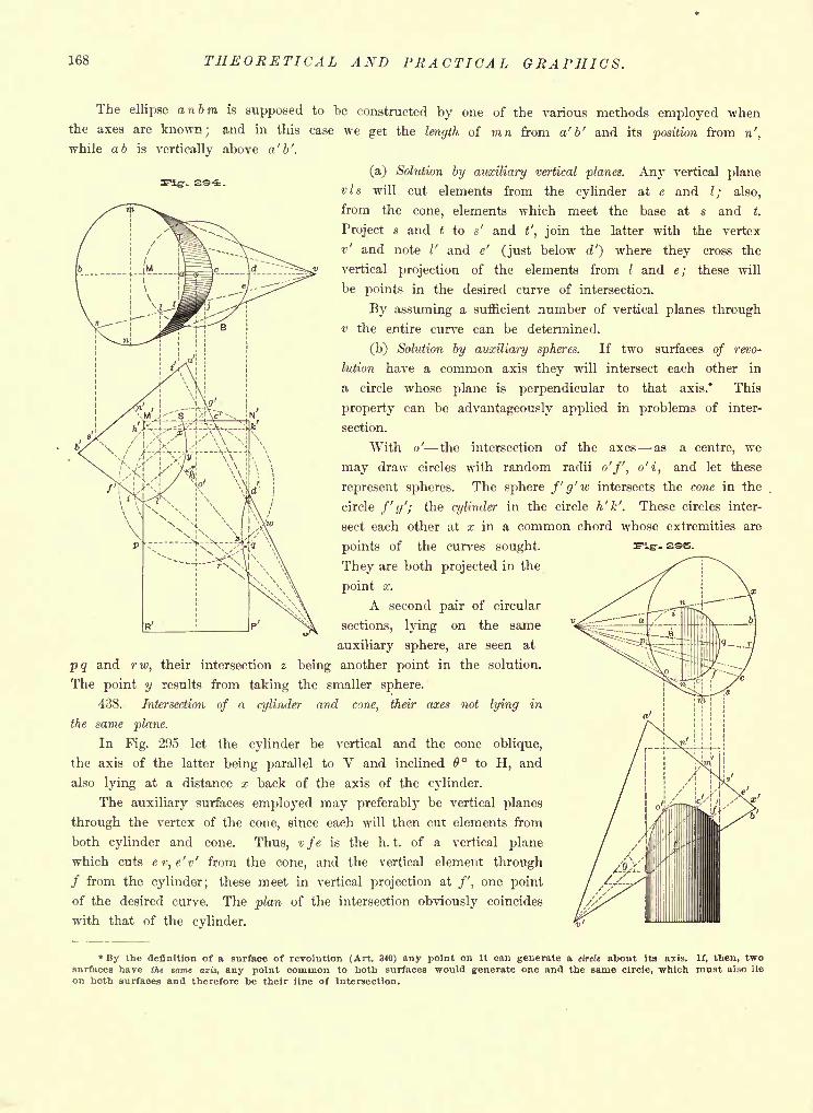
168 THEORETICAL AND PRACTICAL GRAPHICS.
The ellipse anbm is supposed to be constructed by one of the various methods employed whenthe axes are known; and in this case we get the length of mn from a' b' and its position from n',
while a 6 is vertically above a' b'.
(a) Solution by auxiliary vertical planes. Any vertical plane
vis will cut elements from the cylinder at e and /; also,
from the cone, elements which meet the base at s and t.
Project s and t to' and t', join the latter with the vertex
v' and note /' and e' (just below d') where they cross the
vertical projection of the elements from / and e; these will
be points in the desired curve of intersection.
By assuming a sufficient number of vertical planes through
v the entire curve can be determined.
(b) Solution by auxiliary spheres. If two surfaces of revo-
lution have a common axis they will intersect each other in
a circle whose plane is perpendicular to that axis.* This
property can be advantageously applied in problems of inter-
section.
With o' the intersection of the axes as a centre, we
may draw circles with random radii o'f, o'i, and let these
represent spheres. The sphere f'g'w intersects the cone in the
circle /'(/'; the cylinder in the circle h'k'. These circles inter-
sect each other at x in a common chord whose extremities are
pq and rw, their intersection
points of the curves sought.
They are both projected in the
point x.
A second pair of circular
sections, lying on the same
auxiliary sphere, are seen at
z being another point in the solution.
- see.
The point y results from taking the smaller sphere.
438. Intersection of a cylinder and cone, their axes not lying in
the same plane.
In Fig. 295 let the cylinder be vertical and the cone oblique,
the axis of the latter being parallel to V and inclined 6 to H, and
also lying at a distance x back of the axis of the cylinder.
The auxiliary surfaces employed may preferably be vertical planes
through the vertex of the cone, since each will then cut elements from
both cylinder and cone. Thus, vfe is the h. t, of a vertical plane
which cuts e r, e'v' from the cone, and the vertical element through
/ from the cylinder; these meet in vertical projection at /', one point
of the desired curve. The plan of the intersection obviously coincides
with that of the cylinder.
* By the definition of a surface of revolution (Art. 340) any point on it can generate a circle about its axis. If, then, twosurfaces have the same axis, any point common to both surfaces would generate one and the same circle, which must also lie
on both surfaces and therefore be their line of intersection.
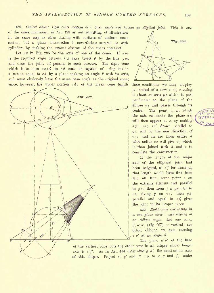
THE INTERSECTION OF SINGLE CURVED SURFACES. 169
This is one
ass.
439. Conical elbow; right cones meeting at a given angle and having an elliptical joint.
of the cases mentioned in Art. 423 as not admitting of illustration
in the same way as when dealing with surfaces of uniform cross
section," but a plane intersection is nevertheless secured as with
cylinders by making the extreme elements of the cones intersect.
Let vx in Fig. 296 be the axis of one of the cones. If xyzis the required angle between the axes bisect it by the line ym,and draw the joint cd parallel to such bisector. The right cone
which is to meet abed on cd must be capable of being cut in
a section equal to cd by a plane making an angle 6 with its axis,
and must obviously have the same base angle as the original cone;
since, however, the upper portion vdc of the given cone fulfills these conditions we may employit instead of a new cone, rotating
it about an axis pt which is per-
pendicular to the plane of the
ellipse dc and passes through its
centre. The point o, in which
the axis vx meets the plane dc,
will then appear at a, by making-
op=ps; sv', drawn parallel to
y z, will be the new direction of
vo; and an arc from centre d
with radius cv will give v', which
is then joined with d and c to
complete the construction.
If the length of the major
axis of the elliptical joint had
been assigned, as ef for example,
that length would have first been
laid off from some point e on
the extreme element and parallel
to ym, then from / a parallel to
ve, giving g on vc; then gh
parallel and equal to ef, gives
the joint in its proper place.
440. Eight cones intersecting in
a non-plane curve; axes meeting at
an oblique angle. Let one cone,
v'.a'b', (Fig. 297) be vertical; the
other, oblique, its axis meeting
v' o' at an angle 0.
The plane a' b' of the base
of the vertical cone cuts the other cone in an ellipse whose longer
axis is e'f. As in Art. 434 determine g' h', the semi-minor axis
of this ellipse. Project e', g' and /' up to e, g and /; make
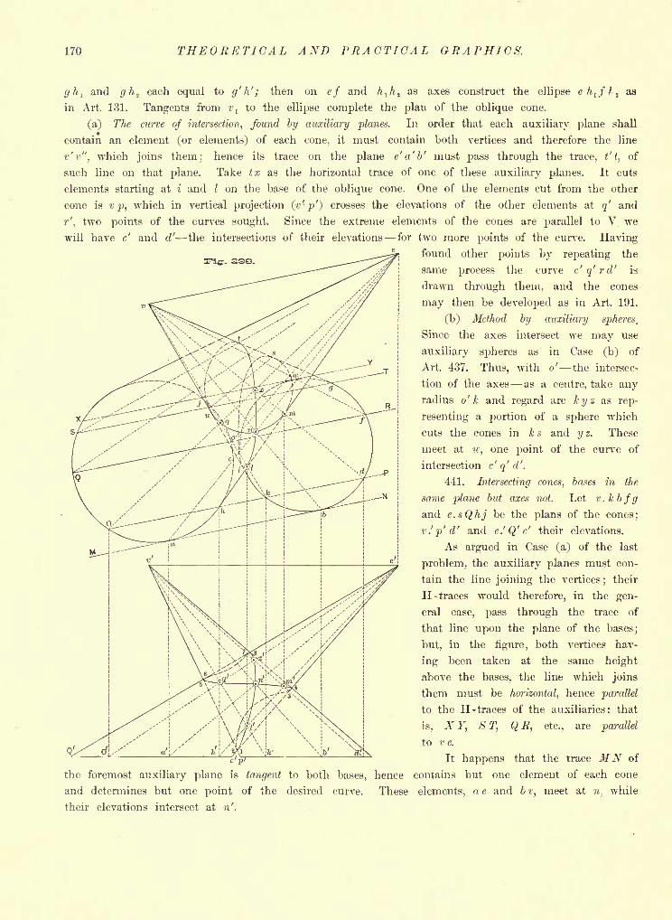
170 THEORETICAL AND PRACTICAL GRAPHICS.
ghi and gh, each equal to g' h' ; then on ef and hlh
jas axes construct the ellipse eh
l fl ias
in Art. 131. Tangents from v, to the ellipse complete the plan of the oblique cone.
(a) The curve of intersection, found by auxiliary planes. In order that each auxiliary plane shall
contain an element (or elements) of each cone, it must contain both vertices and therefore the line
v'r", which joins them; hence its trace on the plane e' a' b' must pass through the trace, t't,
of
such line on that plane. Take tx as the horizontal trace of one of these auxiliary planes. It cuts
elements starting at i and I on the base of the oblique cone. One of the elements cut from the other
cone is v p, which in vertical projection (v'- p'~) crosses the elevations of the other elements at q' and
r', two points of the curves sought. Since the extreme elements of the cones are parallel to V we
will have c' and d' the intersections of their elevations for two more points of the curve. Havingfound other points by repeating the
same process the curve c'q'rd' is
drawn through them, and the cones
may then be developed as in Art. 191.
(b) Method by auxiliary spheres,
Since the axes intersect we may use
auxiliary spheres as in Case (b) of
Art. 437. Thus, with o' the intersec-
tion of the axes as a centre, take anyradius o' k and regard arc kyz as rep-
resenting a portion of a sphere which
cuts the cones in k s and y z. These
meet at w, one point of the curve of
intersection c' q' d'.
441. Intersecting cones, bases in the
same plane but axes not. Let v.kbfgand e.sQhj be the plans of the cones;
v.'p'd' and e.'Q'c' their elevations.
As argued in Case (a) of the last
problem, the auxiliary planes must con-
tain the line joining the vertices;
their
H- traces would therefore, in the gen-
eral case, pass through the trace of
that line upon the plane of the bases;
but, in the figure, both vertices hav-
ing been taken at the same height
above the bases, the line which joins
them must be horizontal, hence parallel
to the H- traces of the auxiliaries: that
is, X Y, S T, Q R, etc., are parallel
to v e.
c-pi It happens that the trace MN of
the foremost auxiliary plane is tangent to both bases, hence contains but one element of each cone
and determines but one point of the desired curve. These elements, a e and 6 v, meet at niwhile
their elevations intersect at n'.
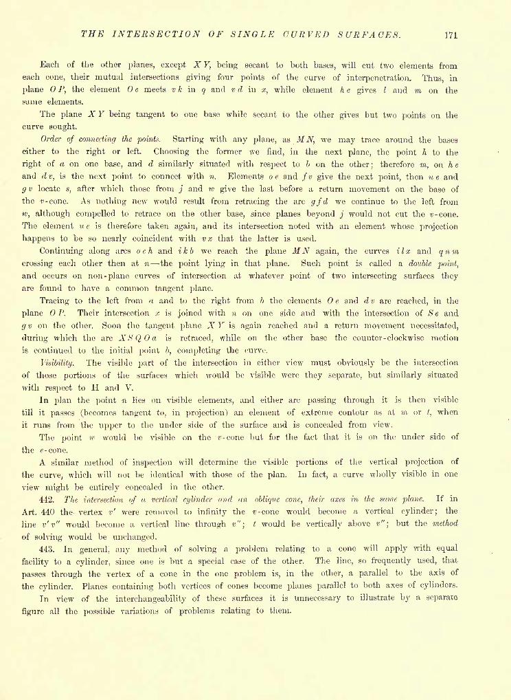
THE INTERSECTION OF SINGLE CURVED SURFACES. 171
Each of the other planes, except X Y, being secant to both bases, will cut two elements from
each cone, their mutual intersections giving four points of the curve of interpenetration. Thus, in
plane P, the element e meets v k in q and v d in x, while element h e gives I and m on the
same elements.
The plane X Y being tangent to one base while secant to the other gives but two points on the
curve sought.
Order of connecting the points. Starting with any plane, as MN, we may trace around the bases
either to the right or left. Choosing the former we find, in the next plane, the point h to the
right of a on one base, and d similarly situated with respect to b on the other;
therefore m, on he
and d v, is the next point to connect with n. Elements o e and / v give the next point, then u e and
g v locate s, after which those from j and w give the last before a return movement on the base of
the t'-cone. As nothing new would result from retracing the arc gfd we continue to the left from
w, although compelled to retrace on the other base, since planes beyond j would not cut the v-cone.
The element u e is therefore taken again, and its intersection noted with an element whose projection
happens to be so nearly coincident with v x that the latter is used.
Continuing along arcs och and ikb we reach the plane MN again, the curves ilx and qnmcrossing each other then at 71 -the point lying in that plane. Such point is called a double point,
and occurs on non- plane curves of intersection at whatever point of two intersecting surfaces they
are found to have a common tangent plane.
Tracing to the left from a and to the right from b the elements e and d v are reached, in the
plane OP. Their intersection x is joined with 71 on one side and with the intersection of Se and
g v on the other. Soon the tangent plane X Y is again reached and a return movement necessitated,
during which the arc XS Q, a is retraced, while on the other base the counter-clockwise motion
is continued to the initial point b, completing the curve.
Visibility. The visible part of the intersection in either view must obviously be the intersection
of those portions of the surfaces which would be visible were they separate, but similarly situated
with respect to H and V.
In plan the point n lies on visible elements, and either arc passing through it is then visible
till it passes (becomes tangent to, in projection) an element of extreme contour as at m ort,
when
it runs from the upper to the under side of the surface and is concealed from view.
The point w would be visible on the 0-cone but for the fact that it is on the under side of
the e-cone.
A similar method of inspection will determine the visible portions of the vertical projection of
the curve, which will not be identical with those of the plan. In fact, a curve wholly visible in one
view might be entirely concealed in the other.
442. The intersection of a vertical cylinder and <tn oblique cone, their axes in the same plane. If in
Art. 440 the vertex v' were removed to infinity the t>-cone would become a vertical cylinder; the
line v' v" would become a vertical line through v";
t would be vertically above v";
but the method
of solving would be unchanged.
443. In general, any method of solving a problem relating to a cone will apply with equal
facility to a cylinder, since one is but a special case of the other. The line, so frequently used, that
passes through the vertex of a cone in the one problem is, in the other, a parallel to the axis of
the cylinder. Planes containing both vertices of cones become planes parallel to both axes of cylinders.
In view of the interchangeability of these surfaces it is unnecessary to illustrate by a separate
figure all the possible variations of problems relating to them.
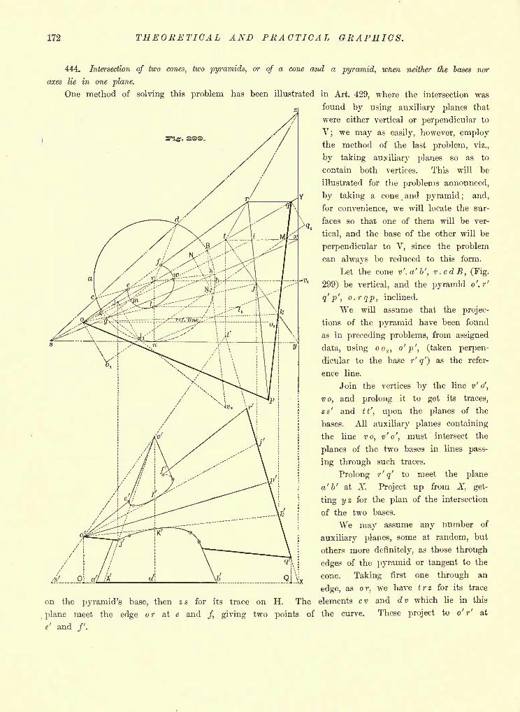
172 THEORETICAL AND PRACTICAL GRAPHICS.
444. Intersection of two cones, two pyramids, or of a cone and a pyramid, wnen neither the bases nor
axes lie in one plane.
One method of solving this problem has been illustrated in Art. 429, where the intersection was
found by using auxiliary planes that
were either vertical or perpendicular to
V; we may as easily, however, employthe method of the last problem, viz.,
by taking auxiliary planes so as to
contain both vertices. This will be
illustrated for the problems announced,
by taking a cone and pyramid ; and,
for convenience, we will locate the sur-
faces so that one of them will be ver-
tical, and the base of the other will be
perpendicular to V, since the problem
can always be reduced to this form.
Let the cone v'.a'b', v.cdB, (Fig.
299) be vertical, and the pyramid o'. r'
q' p', o.rqp, inclined.
We will assume that the projec-
tions of the pyramid have been found
as in preceding problems, from assigned
data, using o o2 ,
o'
p ', (taken perpen-
dicular to the base r' q') as the refer-
ence line.
Join the vertices by the line v' o',
v o, and prolong it to get its traces,
ss' and tt', upon the planes of the
bases. All auxiliary planes containing
the line vo, v' o', must intersect the
planes of the two bases in lines pass-
ing through such traces.
Prolong r' q' to meet the plane
a' b' at X. Project up from X, get-
ting yz for the plan of the intersection
of the two bases.
We may assume any number of
auxiliary planes, some at random, but
others more definitely, as those through
edges of the pyramid or tangent to the
cone. Taking first one through an
edge, as or, we have trz for its trace
on the pyramid's base, then zs for its trace on H. The elements cv and dv which lie in this
plane meet the edge o r at e and /, giving two points of the curve. These project to o' r' at
e' and /'.
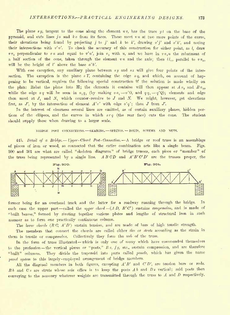
INTERSECTIONS. PRACTICAL ENGINEERING DESIGNS. 173
The plane s y, tangent to the cone along the element u v, has the trace y t on the base of the
pyramid, and cuts lines j o and k o from its faces. These meet v u at two more points of the curve,
their elevations being found by projecting j to j' and k to k', drawing o'j' and o'k', and noting
their intersections with v'u'. To check the accuracy of this construction for either point, asI,
draw
vv1 perpendicular to vu and equal to v'u', join t>, with w, and we have in vv^u the rabatment of
a half section of the cone, taken through the element vu and the axis; then ll lt parallel to vv lf
will be the height of I' above the base a' b'.
With one exception, any auxiliary plane between sy and sz will give four points of the inter-
section. The exception is the plane s Y, containing the edge o q, and which, on account of hap-
pening to be vertical, requires the following special construction if the solution is made wholly on
the plan: Rabat the plane into H; the elements it contains will then appear at Avtand Sv
s ,
while the edge o q will .be seen in ol q l (by making oo
l ^o'0, and fl^i= g'Q); elements and edge
then meet at J, and Nl
which counter - revolve to J and N. We might, however, get elevations
first, as /', by the intersection of element A'v' with edge o'q'; then / from J'.
In the interest of clearness several lines are omitted, as of certain auxiliary planes, hidden por-
tions of the ellipses, and the curves in which srq (the rear face) cuts the cone. The student
should supply these when drawing to a larger scale.
BRIDGE POST CONNECTIONS. GEARING. SPRINGS. BOLTS, SCREWS AND NUTS.
445. Detail of a Bridge. Upper -Chord Post - Connection. A bridge or roof truss is an assemblage
of pieces of iron or wood, so connected that the entire combination acts like a single beam. Figs.
300 and 301 are what are called "skeleton diagrams" of bridge trusses, each piece or "member" of
the truss being represented by a single line. A BCD and A'B'C'D' are the trusses proper, the
former being for an overhead track and the latter for a roadway running through the bridge. In
each case the upper part called the upper chord (AD, B'C') sustains compression, and is made of
"built beams," formed by riveting together various plates and lengths of structural iron in such
manner as to form one practically continuous column.
The lower chords (B C, A' D'*) sustain tension, and are made of bars of high tensile strength.
The members that connect the chords are called either ties or struts according as the strain in
them is tensile or compressive. Collectively they form the web of the truss.
In the form of truss illustrated which is only one of many which have commended themselves
to the profession the vertical pieces or "posts," Be, fg, etc., sustain compression, and are therefore
"built" columns. They divide the trapezoid into parts called panels, which has given the name
panel system to this largely- employed arrangement of bridge members.
All the diagonal members in both figures, excepting A' B' and C' D', are tension bars or rods.
Bb and Cs are struts whose sole office is to keep the posts Ab and Da vertical; said posts then
conveying to the masonry whatever weights are transmitted through the truss to A and D respectively.
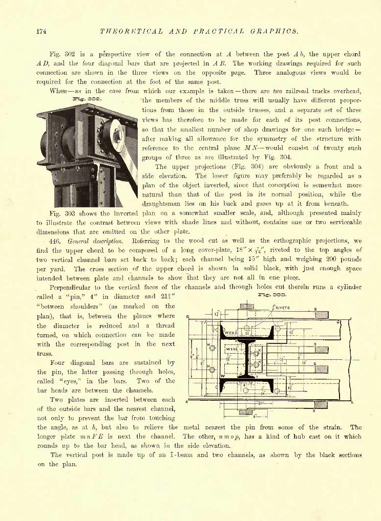
174 THEORETICAL AND PRACTICAL GRAPHICS.
Fig. 302 is a perspective view of the connection at A between the post A b, the upper chord
A D, and the four diagonal bare that are projected in A B. The working drawings required for such
connection are shown in the three views on the opposite page. Three analogous views would be
required for the connection at the foot of the same post.
When as in the case from which our example is taken there are two railroad tracks overhead,
ng. 302. ^6 members of the middle truss will usually have different propor-
tions from those in the outside trusses, and a separate set of three
views has therefore to be made for each of its post connections,
so that the smallest number of shop drawings for one such bridge
after making all allowance for the symmetry of the structure with
reference to the central plane M N- would consist of twenty such
groups of three as are illustrated by Fig. 304.
The upper projections (Fig. 304) are obviously a front and a
side elevation. The lower figure may preferably be regarded as a
plan of the object inverted, since that conception is somewhat more
natural than that of the post in its normal position, while the
draughtsman lies on his back and gazes up at it from beneath.
Fig. 303 shows the inverted plan on a somewhat smaller scale, and, although presented mainly
to illustrate the contrast between views with shade lines and without, contains one or two serviceable
dimensions that are omitted on the other plate.
446. General description. Referring to the wood cut as well as the orthographic projections, we
find the upper chord to be composed of a long cover-plate, 18" x ^", riveted to the top angles of
two vertical channel bars set back to back; each channel being 15" high and weighing 200 pounds
per yard. The cross section of the upper chord is shown in solid black, with just enough space
intended between plate and channels to show that they are not all in one pieqe.
Perpendicular to the vertical faces of the channels and through holes cut therein runs a cylinder
called a "pin," 4" in diameter and 21J"
"between shoulders" (as marked on the
plan), that is, between the planes where
the diameter is reduced and a thread
turned, on which connection can be made
with the corresponding post in the next
truss.
Four diagonal bars are sustained by
the pin, the latter passing through holes,
called "eyes," in the bars. Two of the
bar heads are between the channels.
Two plates are inserted between each
of the outside bars and the nearest channel,
not only to prevent the bar from touching
the angle, as at h, but also to relieve the metal nearest the pin from some of the strain. The
longer plate mnFE is next the channel. The other, nmop, has a kind of hub cast on it which
rounds up to the bar head, as shown in the side elevation.
The vertical post is made up of an I-beam and two channels, as shown by the black sections
on the plan.
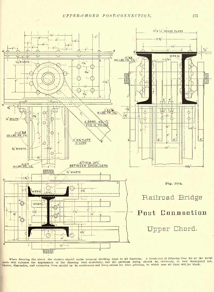
UPPER-CHORD POST-CONNECTION. 175
18"x VIQ' CC
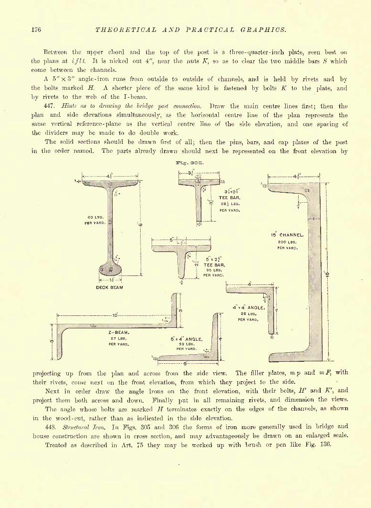
176 THEORETICAL AND PRACTICAL GRAPHICS.
Between the upper chord and the top of the post is a three -quarter -inch plate, seen best on
the plans at if It. It is nicked out 4", near the nuts K, so as to clear the two middle bars S which
conie between the channels.
A 5" X 3
"angle
- iron runs from outside to outside of channels, and is held by rivets and bythe bolts marked H. A shorter piece of the same kind is fastened by bolts K to the plate, and
by rivets to the web of the I-beam.
447. Hints as to drawing the bridge post connection. Draw the main centre lines first; then the
plan and side elevations simultaneously, as the horizontal centre line of the plan represents the
same vertical reference -plane as the vertical centre line of the side elevation, and one spacing of
the dividers may be made to do double work.
The solid sections should be drawn first of all; then the pins, bars, and cap plates of the post
in the order named. The parts already drawn should next be represented on the front elevation by
projecting up from the plan and across from the side view. The filler plates, mp and mF, with
their rivets, come next on the front elevation, from which they project to the side.
Next in order draw the angle irons on the front elevation, with their bolts, H' and K', and
project them both across and down. Finally put in all remaining rivets, and dimension the views.
The angle whose bolts are marked H terminates exactly on the edges of the channels, as shown
in the wood -cut, rather than as indicated in the side elevation.
448. Structural Iron. In Figs. 305 and 306 the forms of iron more generally used in bridge and
house construction are shown in cross section, and may advantageously be drawn on an enlarged scale.
Treated as described in Art. 75 they may be worked up with brush or pen like Fig. 136.
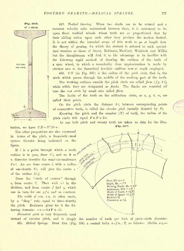
TOOTHED GEARING. HELICAL SPRINGS. 177
-- 3O6.
15' I-BEAM.
449. Toothed Gearing. When two shafts are to be rotated and a
constant velocity ratio maintained between them, it is customary to fix
upon them toothed wheels whose teeth are so proportioned that bytheir sliding action upon each other they produce the motion desired.
It is not within the intended scope of this work to go at length into
the theory of gearing, for which the student is referred to such special-
ized treatises as those of Grant, Robinson, MacCord, Weisbach and Willis;
but the draughtsman will find it to his advantage to be familiar with
the following rapid method of drawing the outlines of the teeth of
a spur wheel, in which a remarkably close approximation is made by
circular arcs to the theoretical involute outlines now so much employed.
450. CN (in Fig. 307) is the radius of the pitch circle, that is, the
circle which passes through the middle of the working part of the tooth.
The working outlines outside the pitch circle are called faces (fg, hi),
while within they are designated as flanks. The flanks are rounded off
into the root circle by small arcs called fillets.
The limits of the teeth on the addendum circle, as a, g, h, m, are
called their points.
On the pitch circle the distance bi, between corresponding points
of consecutive teeth, is called the circular pitch (usually denoted by P).
Knowing the pitch and the number (jV) of teeth, the radius of the
pitch circle will equal P xN -*- 2 ir.
As one inch pitch and twenty teeth are taken as data for the illus-
tration, we have C'JV=3".18+.
The other proportions are also expressed
in terms of the pitch, a frequently -used
system therefor being indicated on the
figure.
If i is a 'point through which a tooth
outline is to pass, draw Ci, and on it as
a diameter describe the semi -circumference
Cs i. An arc from centre',with a radius
of one-fourth Ci, will give the centre s
of the outline hij.
Draw the "circle of centres" through
s, from centre C. Then with * i in the
dividers, and from centre / find q, which
use in turn for arc gfe, and so continue.
The width of rim, vw, is often made,
by a "shop" rule, equal to three - fourths
the pitch. Reuleaux gives for it the fol-
lowing formula: v w= 0.4 P -f .12.
Diametral pitch is very frequently used
instead of circular pitch, and is simply
451. Helical Springs.
-- 3O7.
Pitch (P)= bi = fl
Depth, Mv,=.7 P
Working Depth, Mz,=Addendum, M N,=.3 I?
Width of Tooth, fi,=
Width of Space, ilf ft
BacklashpftClearance, zv,= jo
Jc
the number of teeth per inch of pitch -circle diameter.
Draw first (Fig. 308) a central helix acfm..T, as follows: Divide a a,
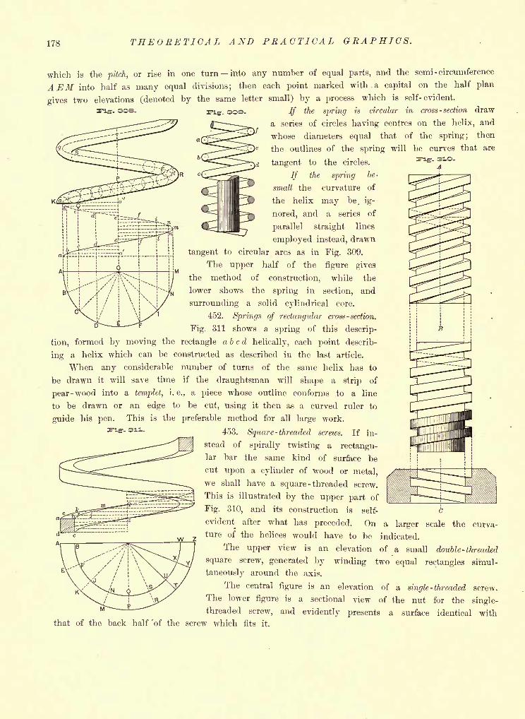
178 THEORETICAL AND PRACTICAL GRAPHICS.
which is the pitch, or rise in one turn into any number of equal parts, and the semi -circumference
A EM into half as many equal divisions; then each point marked with, a capital on the half plan
gives two elevations (denoted by the same letter small) by a process which is self-evident.
Fig. 308.. 30S. If the spring is circular in cross - section draw
a series of circles having centres on the helix, and
whose diameters equal that of the spring; then
the outlines of the spring will be curves that are
tangent to the circles.
If the spring be-
small the curvature of
the helix may be. ig-
nored, and a series of
parallel straight lines
employed instead, drawn
tangent to circular arcs as in Fig. 309.
The upper half of the figure gives
the method of construction, while the
lower shows the spring in section, and
surrounding a solid cylindrical core.
452. Springs of rectangular cross -section.
Fig. 311 shows a spring of this descrip-
tion, formed by moving the rectangle a b c d helically, each point describ-
ing a helix which can be constructed as described in the last article.
When any considerable number of turns of the same helix has to
be drawn it will save time if the draughtsman will shape a strip of
pear -wood into a templet, i.e., a piece whose outline conforms to a line
to be drawn or an edge to be cut, using it then as a curved ruler to
guide his pen. This is the preferable method for all large work.
453. Square -threaded screws. If in-
stead of spirally twisting a rectangu-
lar bar the same kind of surface be
cut upon a cylinder of wood or metal,
we shall have a square -threaded screw.
This is illustrated by the upper part of
Fig. 310, and its construction is self-
evident after what has preceded. On a largerture of the helices would have to be indicated.
The upper view is an elevation of a small double -threaded
square screw, generated by winding two equal rectangles simul-
taneously around the axis.
The central figure is an elevation of a single -threaded screw,
figure is a sectional view of the nut for the single-
curva-
The lower
threaded screw, and evidently presents a surface identical withthat of the back half 'of the screw which fits it.
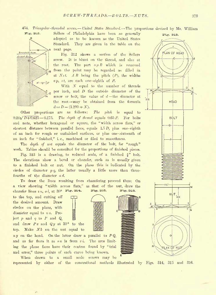
SCREW-THREADS. BOLTS. NUTS. 179
454. Triangular-threaded screws. United States Standard. The proportions devised by Mr. William
Other
Sellers of Philadelphia have been so generally
adopted as to be known as the United States
Standard. They are given in the table on the
next page.
Fig. 312 shows a section of the Sellers
screw. It is blunt on the thread, and also at
the root. The part o p B which is removed
. B from the point may be regarded as filled in
at Ns t. A B being the pitch (P), the widths
op, $t,
are each one -eighth of P.
With N equal to the number of threads
per inch, and D the outside diameter of the
screw or bolt, the value of d the diameter at
the root may be obtained from the formula
d= >-(!.299 H-iV).
proportions are as follows: The pitch is equal to
0.24A/ ,0+0.625 0.175. The depth of thread equals 0.65 P. For bolts
and nuts, whether hexagonal or square, the "width across flats," or
shortest distance between parallel faces, equals 1.5 D, plus one- eighth
of an inch for rough or unfinished surfaces, or plus one - sixteenth of
an inch for"finished," i. e., machined or filed to smoothness.
The depth of nut equals the diameter of the bolt, for "rough"work. Tables should be consulted for the proportions of finished pieces.
Fig. 313 is a drawing, to reduced scale, of a finished"
bolt.
The elevations show a bevel or chamfer, such as is usually given
to a finished bolt or nut. On the plans this is indicated by the
circles of diameter p q, the latter usually a little more than three-
fourths of the diameter a d.
To draw the lines resulting from
a view showing "width across flats,"
chamfer lines z u, o i, at 30
to the top, and cutting off
the desired amount. Draw
circles on the plans, with
diameter equal to u o. Pro-
ject p and q to P and Q,
and draw Px and Qy at 30 to the
top. Make Nk on the nut equal to
n y on the head. On the latter draw a parallel to P Q,
and as far from it as ou is from vi. The arcs limit-
ing the plane faces have their centres found by "trial
and error," three points of each curve being known.
When drawn to a small scale screws may be
represented by either of the conventional methods illustrated
chamfering proceed thus: On
as that of the nut, draw the
r- sis.
HEAD
BOLT
NUT
by Figs. 314, 315 and 316.
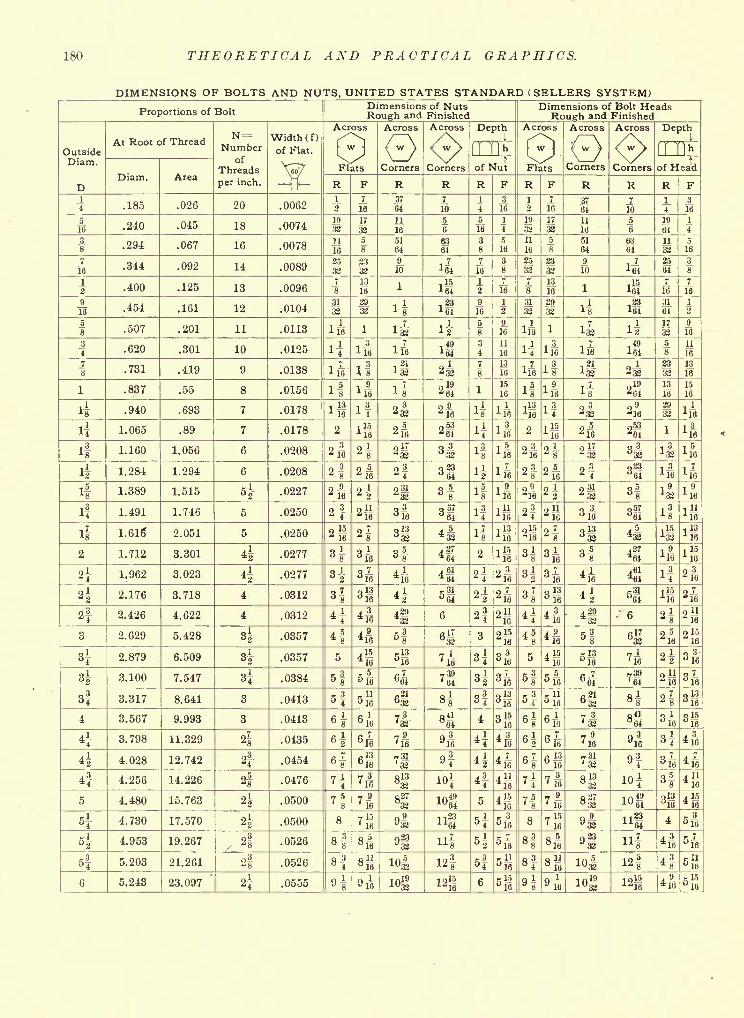
180 THEORETICAL AND PRACTICAL GRAPHICS.
DIMENSIONS OF BOLTS AND NUTS, UNITED STATES STANDARD ( SELLERS SYSTEM)
Proportions of Bolt
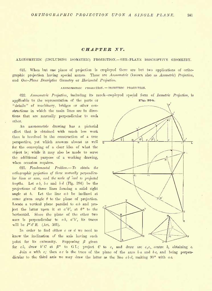
ORTHOGRAPHIC PROJECTION UPON A SINGLE PLANE. 241
CHAPTER XV.
AXONOMETRIC (INCLUDING ISOMETRIC) PROJECTION. ONE-PLANE DESCRIPTIVE GEOMETRY.
621. When but one plane of projection is employed there are but two applications of ortho-
graphic projection having special names. These are Axonometric (known also as Axometric) Projection,
and One- Plane Descriptive Geometry or Horizontal Projection.
AXONOMETRIC PROJECTION. ISOMETRIC PROJECTION.
622. Axonometric Projection, including its much - employed special form of Isometric Projection, is
applicable to the representation of the parts or
"details" of machinery, bridges or other con-
structions in which the main lines are in direc-
tions that are mutually perpendicular to each
other.
An axonometric drawing has a pictorial
effect that is obtained with much less work
than is involved in the construction of a true
perspective, yet which answers almost as well
for the conveying of a clear idea of what the
object is; while it may also be made to serve
the additional purpose of a working drawing,
when occasion requires.
623. Fundamental Problem. To obtain the
orthographic projection of three mutually perpendicu-
lar lines or axes, and the scale of real to projected
lengths. Let a b, be and b d (Fig. 394) be the
projections of three lines forming a solid right
angle at b. Let the line a b be inclined at
some given angle to the plane of projection.
Locate a vertical plane parallel to a b and pro-
ject the latter upon it at a 'b', at 6 to the
horizontal. Since the plane of the other two
axes is perpendicular to ab, a'b', its traces
will be P'd'R. (Art. 303).
In order to find either c or d we need to
know the inclination of the axis having such
point for its extremity. Supposing /3 given
for cb, draw b' C at /J to GL; project C to c, and draw arc c^, centre b, obtaining c.
Join a with c; then a c is the trace of the plane of the axes 6 a and b c, and being perpen-
dicular to the third axis we may draw the latter as the line ebd, making 90 with ac.
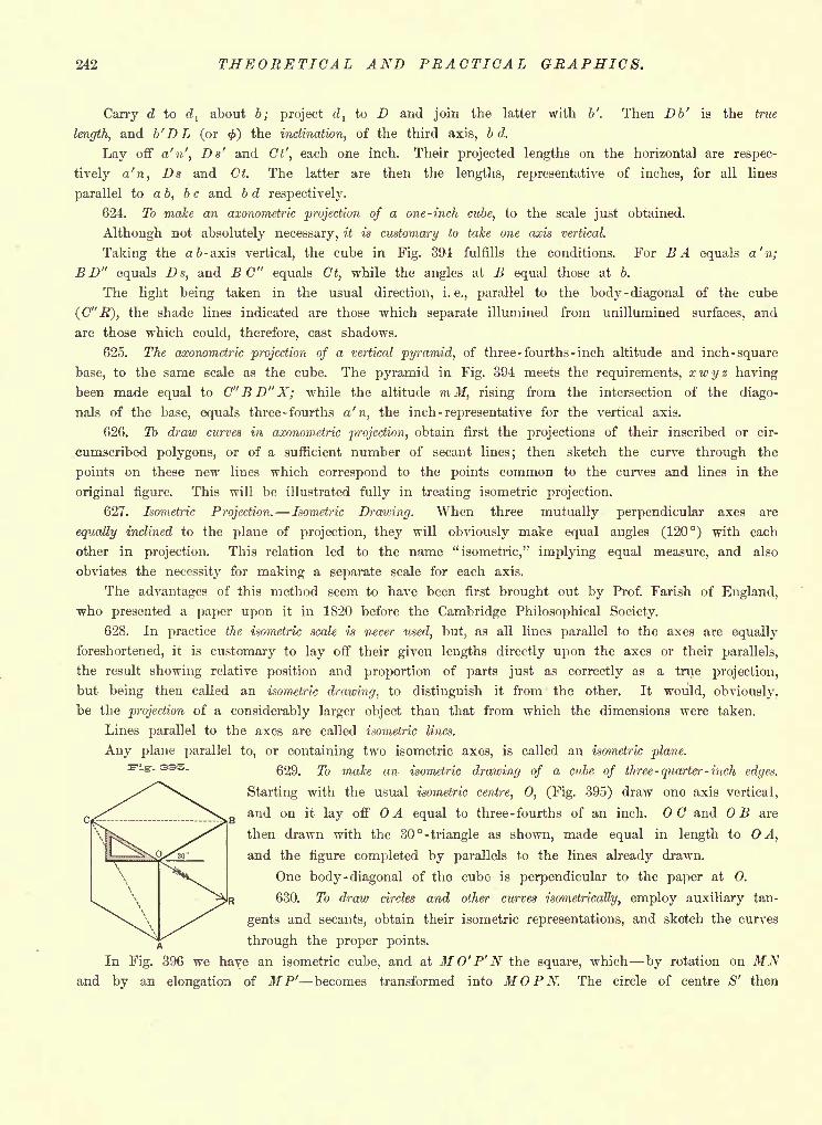
242 THEORETICAL AND PRACTICAL GRAPHICS.
Carry d to dl
about 6; project dl
to D and join the latter with b'. Then Db' is the true
length, and b'DL (or <) the inclination, of the third axis, b d.
Lay off a'n', Da' and (7', each one inch. Their projected lengths on the horizontal are respec-
tively a'n, Ds and Ct. The latter are then the lengths, representative of inches, for all lines
parallel to ab, be and b d respectively.
624. To make an axonometric projection of a one-inch cube, to the scale just obtained.
Although not absolutely necessary, it is customary to take one axis vertical.
Taking the a b- axis vertical, the cube in Fig. 394 fulfills the conditions. For BA equals a'n;
B D" equals Ds, and EG" equals Ct, while the angles at B equal those at 6.
The light being taken in the usual direction, i.e., parallel to the body -diagonal of the cube
(G" R), the shade lines indicated are those which separate illumined from unillumined surfaces, and
are those which could, therefore, cast shadows.
625. The axonometric projection of a vertical pyramid, of three -fourths -inch altitude and inch -square
base, to the same scale as the cube. The pyramid in Fig. 394 meets the requirements, xwyz having
been made equal to C"BD"X; while the altitude mM, rising from the intersection of the diago-
nals of the base, equals three -fourths a'n, the inch -representative for the vertical axis.
626. To draw curves in axonometric projection, obtain first the projections of their inscribed or cir-
cumscribed polygons, or of a sufficient number of secant lines; then sketch the curve through the
points on these new lines which correspond to the points common to the curves and lines in the
original figure. This will be illustrated fully in treating isometric projection.
627. Isometric Projection. -Isometric Drawing. When three mutually perpendicular axes are
equally inclined to the plane of projection, they will obviously make equal angles (120) with each
other in projection. This relation led to the name "isometric," implying equal measure, and also
obviates the necessity for making a separate scale for each axis.
The advantages of this method seem to have been first brought out by Prof. Farish of England,
who presented a paper upon it in 1820 before the Cambridge Philosophical Society.
628. In practice the isometric scale is never used, but, as all lines parallel to the axes are equally
foreshortened, it is customary to lay off their given lengths directly upon the axes or their parallels,
the result showing relative position and proportion of parts just as correctly as a true projection,
but being then called an isometric drawing, to distinguish it from the other. It would, obviously,
be the projection of a considerably larger object than that from which the dimensions were taken.
Lines parallel to the axes are called isometric lines.
Any plane parallel to, or containing two isometric axes, is called an isometric plane.
629. To make an isometric drawing of a cube of three -quarter -inch edges.
Starting with the usual isometric centre, 0, (Fig. 395) draw one axis vertical,
and on it lay off OA equal to three -fourths of an inch. 00 and OB are
then drawn with the 30 -triangle as shown, made equal in length to A,
and the figure completed by parallels to the lines already drawn.
One body -diagonal of the cube is perpendicular to the paper at 0.
630. To draw circles and other curves isometrically, employ auxiliary tan-
gents and secants, obtain their isometric representations, and sketch the curves
through the proper points.
In Fig. 396 we have an isometric cube, and at MO'P'N the square, which by rotation on MNand by an elongation of M P' becomes transformed into MOPN. The circle of centre S' then
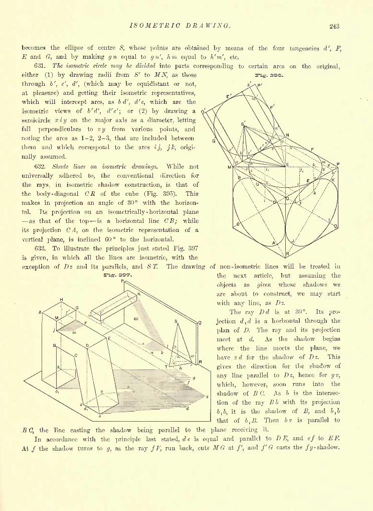
ISOMETRIC DRAWING. 243
becomes the ellipse of centre S, whose points are obtained by means of the four tangencies d', F,
E and G, and by making gn equal to gn', hm equal to h'm', etc.
631. The isometric circle may be divided into parts corresponding to certain arcs on the original,
either (1) by drawing radii from <S" to MN, as those
through b', c', d', (which may be equidistant or not,
at pleasure) and getting their isometric representatives,
which will intercept arcs, as b d', d'e, which are the
isometric views of b'd', d'e'; or (2) by drawing a
semicircle x i y on the major axis as a diameter, letting
fall perpendiculars to xy from various points, and
noting the arcs as 1-2, 2-3, that are included between
them and which correspond to the arcs ij, j k, origi-
nally assumed.
632. Shade lines on isometric drawings. While not
universally adhered to, the conventional direction for
the rays, in isometric shadow construction, is that of
the body -diagonal CR of the cube (Fig. 395). This
makes in projection an angle of 30 with the horizon-
tal. Its projection on an isometrically- horizontal plane
as that of the top is a horizontal line CB; while
its projection CA, on the isometric representation of a
vertical plane, is inclined 60 to the horizontal.
633. To illustrate the principles just stated Fig. 397
is given, in which all the lines are isometric, with the
exception of Dz and its parallels, and ST. The drawing of non- isometric lines will be treated in
the next article, but assuming the
objects as given whose shadows we
are about to construct, we may start
with any line, as Dz.
The ray Dd is at 30. Its pro-
jection dld is a horizontal through the
plan of D. The ray and its projection
meet at d. As the shadow begins
where the line meets the plane, we
have z d for the shadow of D z. This
gives the direction for the shadow of
any line parallel to Dz, hence for yv,
which, however, soon runs into the
shadow of B C. As b is the intersec-
tion of the ray Bb with its projection
&!&, it is the shadow of B, and b^b
that of b^B. Then bv is parallel to
B 0, the line casting the shadow being parallel to the plane receiving it.
In accordance with the principle last stated, de is equal and parallel to D E, and ef to E F.
At / the shadow turns to g, as the ray fF, run back, cuts M G at /', and f'G casts the Jg- shadow.
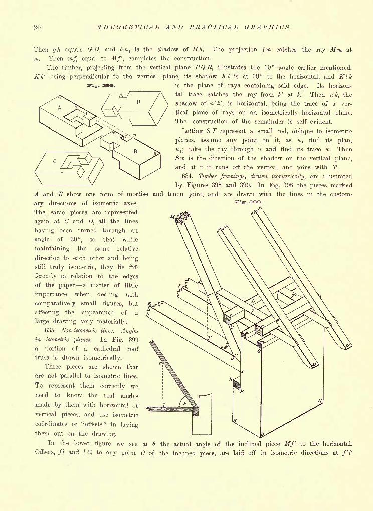
244 THEORETICAL AND PRACTICAL GRAPHICS.
ase.
Then gh equals G H',
and hhl
is the shadow of Hh. The projection jm catches the ray Mm at
m. Then m/, equal to Mf, completes the construction.
The timber, projecting from the vertical plane PQR, illustrates the 60 -angle earlier mentioned.
Kk' being perpendicular to the vertical plane, its shadow Kl is at 60 to the horizontal, and Klkis the plane of rays containing said edge. Its horizon-
tal trace catches the ray from k' at k. Then nk, the
shadow of n'k', is horizontal, being the trace of a ver-
tical plane of rays on an isometrically -horizontal plane.
The construction of the remainder is self-evident.
Letting S T represent a small rod, oblique to isometric
planes, assume any point on it, as u; find its plan,
M,; take the ray through u and find its trace w. Then
Sw is the direction of the shadow on the vertical plane,
and at r it runs off the vertical and joins with T.
634. Timber framings, drawn isometrically, are illustrated
by Figures 398 and 399. In Fig. 398 the pieces marked
A and B show one form of mortise and tenon joint, and are drawn with the lines in the custom-
ary directions of isometric axes.
The same pieces are represented
again at C and D, all the lines
having been turned through an
angle of 30, so that while
maintaining the same relative
direction to each other and being
still truly isometric, they lie dif-
ferently in relation to the edges
of the paper a matter of little
importance when dealing with
comparatively small figures, but
affecting the appearance of a
large drawing very materially.
635. Non-isometric lines. Angles
in isometric planes. In Fig. 399
a portion of a cathedral roof
truss is drawn isometrically.
Three pieces are shown that
are not parallel to isometric lines.
To represent them correctly we
need to know the real angles
made by them with horizontal or
vertical pieces, and use isometric
coordinates or "offsets" in laying
them out on the drawing.
In the lower figure we see at 6 the actual angle of the inclined piece Mf to the horizontal.
Offsets, fl and I C, to any point of the inclined piece, are laid off in isometric directions at f'V
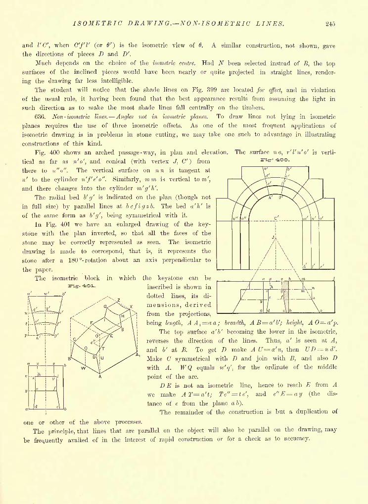
ISOMETRIC DRAWING. NON-ISOMETRIC LINES. 245
-iOO.
and I'C', when C"/T (or 0') is the isometric view of 6. A similar construction, not shown, gave
the directions of pieces D and D'.
Much depends on the choice of the isometric centre. Had N been selected instead of B, the top
surfaces of the inclined pieces would have been nearly or quite projected in straight lines, render-
ing the drawing far less intelligible.
The student will notice that the shade lines on Fig. 399 are located for effect, and in violation
of the usual rule, it having been found that the best appearance results from assuming the light in
such direction as to make the most shade lines fall centrally on the timbers.
636. Non- isometric lines. Angles not in isometric planes. To draw lines not lying in isometric
planes requires the use of three isometric offsets. As one of the most frequent applications of
isometric drawing is in problems in stone cutting, we may take one such to advantage in illustrating
constructions of this kind.
Fig. 400 shows an arched passage-way, in plan and elevation. The surface no, r'l'n'o' is verti-
tical as far as n'o', and conical (with vertex J, C") from
there to n"o". The vertical surface on nn is tangent at
n' to the cylinder n'f'e'o". Similarly, mm is vertical torn',
and there changes into the cylinder m'g'h'.
The radial bed b' g' is indicated on the plan (though not
in full size) by parallel lines at bcfigzb. The bed a'h' is
of the same form as b'g', being symmetrical with it.
In Fig. 401 we have an enlarged drawing of the key-
stone with the plan inverted, so that all the faces of the
stone may be correctly represented as seen. The isometric
drawing is made to correspond, that is, it represents the
stone after a 180 - rotation about an axis perpendicular to
the paper.
The isometric block in which
fig- -ioi.
b'
the keystone can be
inscribed is shown in
dotted lines, its di-
mensions, derived
from the proj ections,
being length, AA^aa; breadth, AB=a'b'; height, A0= a'p.
The top surface a'b' becoming the lower in the isometric,
reverses the direction of the lines. Thus, a' is seen at A,
and b' at B. To get D make AU=a'u, then UD ud'.
Make C symmetrical with D and join with B, and also Dwith A. WQ equals w'q', for the ordinate of the middle
point of the arc.
DE is not an isometric line, hence to reach E from A
we make ATa't; Te"--=te', and e"E=ay (the dis-
tance of e from the plane a 6).
The remainder of the construction is but a duplication of
one or other of the above processes.
The principle, that lines that are parallel on the object will also be parallel on the drawing, may
be frequently availed of in the interest of rapid construction or for a check as to accuracy.
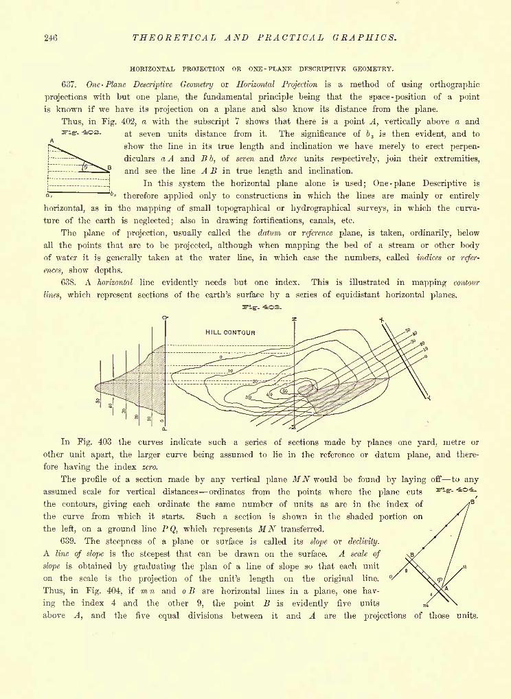
246 THEORETICAL AND PRACTICAL GRAPHICS.
HORIZONTAL PROJECTION OR ONE -PLANE DESCRIPTIVE GEOMETRY.
637. One -Plane Descriptive Geometry or Horizontal Projection is a method of using orthographic
projections with but one plane, the fundamental principle being that the space-position of a point
is known if we have its projection on a plane and also know its distance from the plane.
Thus, in Fig. 402, a with the subscript 7 shows that there is a point A, vertically above a and
at seven units distance from it. The significance of 6 3 is then evident, and to
show the line in its true length and inclination we have merely to erect perpen-
diculars a A and B b, of seven and three units respectively, join their extremities,
and see the line A B in true length and inclination.
In this system the horizontal plane alone is used; One -plane Descriptive is
<*J~* 3 therefore applied only to constructions in which the lines are mainly or entirely
horizontal, as in the mapping of small topographical or hydrographical surveys, in which the curva-
ture of the earth is neglected; also in drawing fortifications, canals, etc.
The plane of projection, usually called the datum or reference plane, is taken, ordinarily, below
all the points that are to be projected, although when mapping the bed of a stream or other bodyof water it is generally taken at the water line, in which case the numbers, called indices or refer-
ences, show depths.
638. A horizontal line evidently needs but one index. This is illustrated in mapping contour
lines, which represent sections of the earth's surface by a series of equidistant horizontal planes.
In Fig. 403 the curves indicate such a series of sections made by planes one yard, metre or
other unit apart, the larger curve being assumed to lie in the reference or datum plane, and there-
fore having the index zero.
The profile of a section made by any vertical plane MN would be found by laying off to any
assumed scale for vertical distances ordinates from the points where the plane cuts
the contours, giving each ordinate the same number of units as are in the index of
the curve from which it starts. Such a section is shown in the shaded portion on
the left, on a ground line PQ, which represents MN transferred.
639. The steepness of a plane or surface is called its slope or declivity.
A line of slope is the steepest that can be drawn on the surface. A scale of
slope is obtained by graduating the plan of a line of slope so that each unit
on the scale is the projection of the unit's length on the original line.
Thus, in Fig. 404, if mn and o B are horizontal lines in a plane, one hav-
ing the index 4 and the other 9, the point B is evidently five units
above A, and the five equal divisions between it and A are the projections of those units.
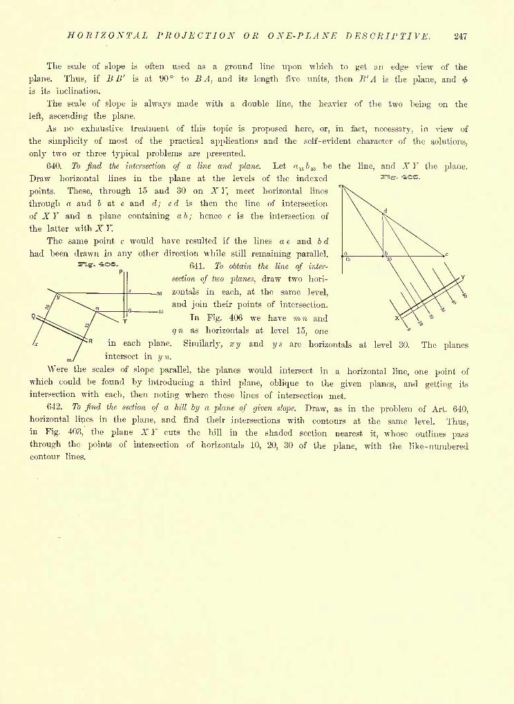
HORIZONTAL PROJECTION OR ONE-PLANE DESCRIPTIVE. 247
-- -40E.
The scale of slope is often used as a ground line upon which to get an edge view of the
plane. Thus, if B B' is at 90 to B A, and its length five units, then B'A is the plane, and <
is its inclination.
The scale of slope is always made with a double line, the heavier of the two being on the
left, ascending the plane.
As no exhaustive treatment of this topic is proposed here, or, in fact, necessary, in view of
the simplicity of most of the practical applications and the self-evident character of the solutions,
only two or three typical problems are presented.
640. To find the intersection of a line and plane. Let a156 30 be the line, and XY the plane.
Draw horizontal lines in the plane at the levels of the iiidexed
points. These, through 15 and 30 on X F, meet horizontal lines
through a and 6 at e and d; ed is then the line of intersection
of X Y and a plane containing ab; hence c is the intersection of
the latter with X Y.
The same point c would have resulted if the lines a e and b d
had been drawn in any other direction while still remaining parallel.
641. To obtain the line of inter-
section of two planes, draw two hori-
zontals in each, at the same level,
and join their points of intersection.
In Fig. 406 we have m n and
qn as horizontals at level 15, one;R in each plane. Similarly, xy and ys are horizontals at level 30. The planes
intersect in y n.
Were the scales of slope parallel, the planes would intersect in a horizontal line, one point of
which could be found by introducing a third plane, oblique to the given planes, and getting its
intersection with each, then noting where these lines of intersection met.
642. To find the section of a hill by a plane of given slope. Draw, as in the problem of Art. 640,
horizontal lines in the plane, and find their intersections with contours at the same level. Thus,in Fig. 403, the plane X Y cuts the hill in the shaded section nearest it, whose outlines pass
through the points of intersection of horizontals 10, 20, 30 of the plane, with the like - numberedcontour lines.
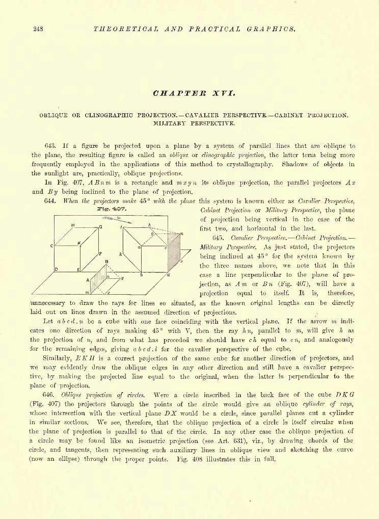
248 THEORETICAL AND PRACTICAL GRAPHICS.
CHAPTER XVI.
OBLIQUE OR CLINOGEAPHIC PROJECTION. CAVALIEK PERSPECTIVE. CABINET PROJECTION.MILITARY PERSPECTIVE.
643. If a figure be projected upon a plane by a system of parallel lines that are oblique to
the plane, the resulting figure is called an oblique or clinographic projection, the latter term being more
frequently employed in the applications of this method to crystallography. Shadows of objects in
the sunlight are, practically, oblique projections.
In Fig. 407, ABnm is a rectangle and mxyn its oblique projection, the parallel projectors Axand By being inclined to the plane of projection.
644. When the projectors make 45 with the plane this system is known either as Cavalier Perspective,
Cabinet Projection or Military Perspective, the plane
of projection being vertical in the case of the
first two, and horizontal in the last.
645. Cavalier Perspective. Cabinet Projection.
Military Perspective. As just stated, the projectors
being inclined at 45 for the system known by
the three names above, we note that in this
case a line perpendicular to the plane of pro-
jection, as A m or B n (Fig. 407), will have a
projection equal to itself. It is, therefore,
unnecessary to draw the rays for lines so situated, as the known original lengths can be directly
laid out on lines drawn in the assumed direction of projections.
Let a b c d . n be a cube with one face coinciding with the vertical plane. If the arrow m indi-
cates one direction of rays making 45 with V, then the ray hn, parallel to m, will give h as
the projection of n, and from what has preceded we should have c h equal to c n, and analogously
for the remaining edges, giving a b c d . i for the cavalier perspective of the cube.
Similarly, EKH is a correct projection of the same cube for another direction of projectors, and
we may evidently draw the oblique edges in any other direction and still have a cavalier perspec-
tive, by making the projected line equal to the original, when the latter is perpendicular to the
plane of projection.
646. Oblique projection of circles. Were a circle inscribed in the back face of the cube DK G
(Fig. 407) the projectors through the points of the circle would give an oblique cylinder of rays,
whose intersection with the vertical plane DX would be a circle, since parallel planes cut a cylinder
in similar sections. We see, therefore, that the oblique projection of a circle is itself circular when
the plane of projection is parallel to that of the circle. In any other case the oblique projection of
a circle may be found like an isometric projection (see Art. 631), viz., by drawing chords of the
circle, and tangents, then representing such auxiliary lines in oblique view and sketching the curve
(now an ellipse) through the proper points. Fig. 408 illustrates this in full.
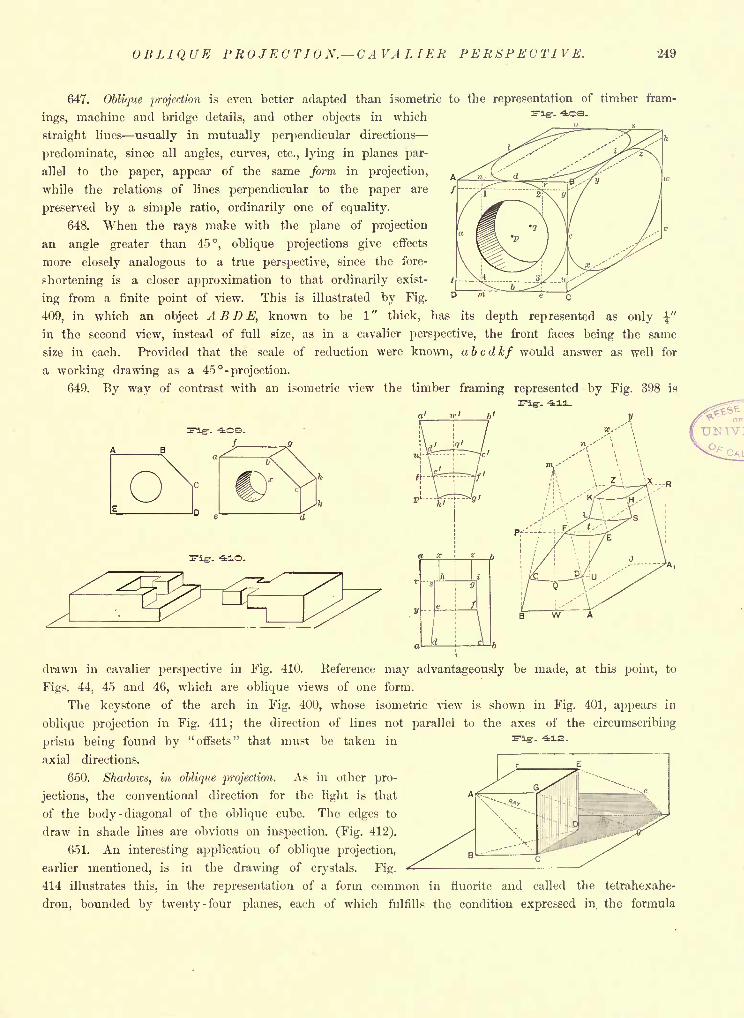
OBLIQUE PROJECTION. CAVALIER PERSPECTIVE. 249
647. Oblique projection is even better adapted than isometric to the representation of timber fram-
ings, machine and bridge details, and other objects in which
straight lines usually in mutually perpendicular directions
predominate, since all angles, curves, etc., lying in planes par-
allel to the paper, appear of the same form in projection,
while the relations of lines perpendicular to the paper are
preserved by a simple ratio, ordinarily one of equality.
648. When the rays make with the plane of projection
an angle greater than 45, oblique projections give effects
more closely analogous to a true perspective, since the fore-
shortening is a closer approximation to that ordinarily exist-
ing from a finite point of view. This is illustrated by Fig.
409, in which an object A B D E, known to be 1" thick, has its depth represented as only \"
in the second view, instead of full size, as in a cavalier perspective, the front faces being the same
size in each. Provided that the scale of reduction were known, abcdkf would answer as well for
a working drawing as a 45 -projection.
649. By way of contrast with an isometric view the timber framing represented by Fig. 398 is
q' ic' b>
f. -41O.
drawn in cavalier perspective in Fig. 410. Reference may advantageously be made, at this point, to
Figs. 44, 45 and 46, which are oblique views of one form.
The keystone of the arch in Fig. 400r whose isometric view is shown in Fig. 401, appears in
oblique projection in Fig. 411; the direction of lines not parallel to the axes of the circumscribing
prism being found by "offsets" that must be taken in
axial directions.
650. Shadows, in oblique projection. As in other pro-
jections, the conventional direction for the light is that A
of the body -diagonal of the oblique cube. The edges to
draw in shade lines are obvious on inspection. (Fig. 412).
651. An interesting application of oblique projection,
earlier mentioned, is in the drawing of crystals. Fig.
414 illustrates this, in the representation of a form common in rluorite and called the tetrahexahe-
dron, bounded by twenty -four planes, each of which fulfills the condition expressed in the formula
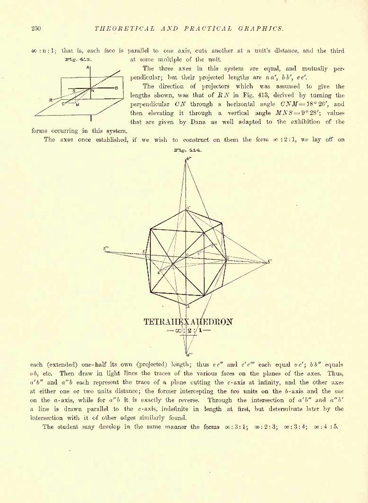
250 THEORETICAL AND PRACTICAL GRAPHICS.
co : n : 1;
that is, each face is parallel to one axis, cuts another at a unit's distance, and the third
at some multiple of the unit.
The three axes in this system are equal, and mutually per-
pendicular; but their projected lengths are a a', bb', cc'.
The direction of projectors which was assumed to give the
lengths shown, was that of EN in Fig. 413, derived by turning the
perpendicular CN through a horizontal angle CNM= 18 26', and
then elevating it through a vertical angle MNS= $ 28'; values
that are given by Dana as well adapted to the exhibition of the
forms occurring in this system.
The axes once established, if we wish to construct on them the form oo : 2 : 1, we lay off on
each (extended) one-half its own (projected) length; thus cc" and c'c'" each equal oc'\ bb" equals
ob, etc. Then draw in light lines the traces of the various faces on the planes of the axes. Thus,
a'b" and a" b each represent the trace of a plane cutting the c-axis at infinity, and the other axes
at either one or two units distance; the former intercepting the two units on the b -axis and the one
on the a -axis, while for a" b it is exactly the reverse. Through the intersection of a'b" and a"b'
a line is drawn parallel to the c-axis, indefinite in length at first, but determinate later by the
intersection with it of other edges similarly found.
The student may develop in the same manner the forms oo:3:l; oo:2:3; oo:3:4; oo:4:5.
APPENDIX
Table of Proportions of Standard Washers Page II
Section of Standard Rail, one hundred pounds to the yard Page III
Sectional View of Allen -Richardson Slide Valve Page IV
Figures serviceable for variations of problems in Projection, Sections, Conversion of views
from one system of projection to another, Shadows, Perspective, etc Page VNote to Art. 113, on the Sections cut from the Annular Torus by a Bi- tangent Plane . Page VI
Note to Art. 131, on the Projection of a Circle in an Ellipse Page VI
The Nomenclature and Double Generation of Trochoids Pages VII-XIV
Alphabets and Ornamental Devices for Titles Pages XV-XXVIII
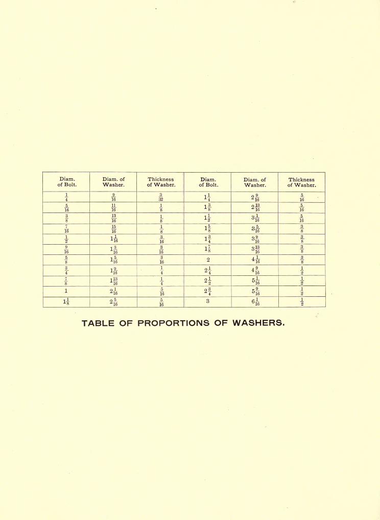
Diam.of Bolt.
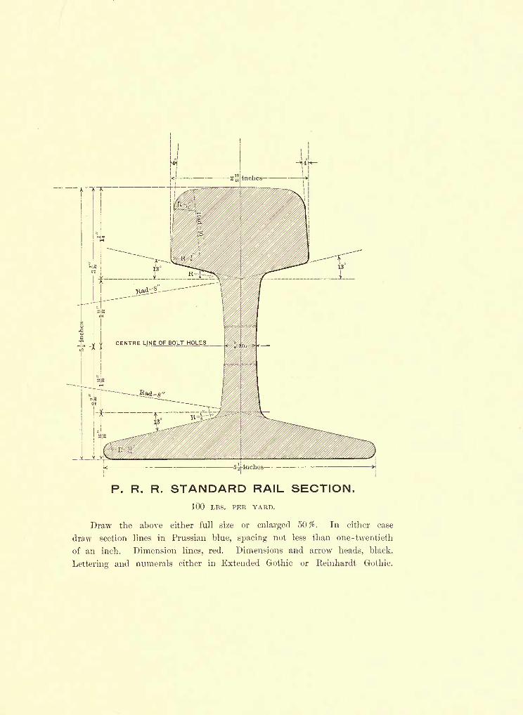
P. R. R. STANDARD RAIL SECTION.
100 LBS. PER YARD.
Draw the above either full size or enlarged 50%. In either case
draw section lines in Prussian blue, spacing not less than one -twentieth
of an inch. Dimension lines, red. Dimensions and arrow heads, black.
Lettering and numerals either in Extended Gothic or Reinhardt Gothic.
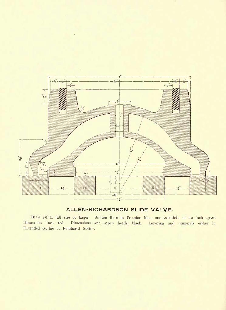
!L" x i"
~4^H*-*i^i'H i
ALLEN-RICHARDSON SLIDE VALVE.Draw either full size or larger. Section lines in Prussian blue, one -twentieth of an inch apart.
Dimension lines, red. Dimensions and arrow heads, black. Lettering and numerals either in
Extended Gothic or Reinhardt Gothic.
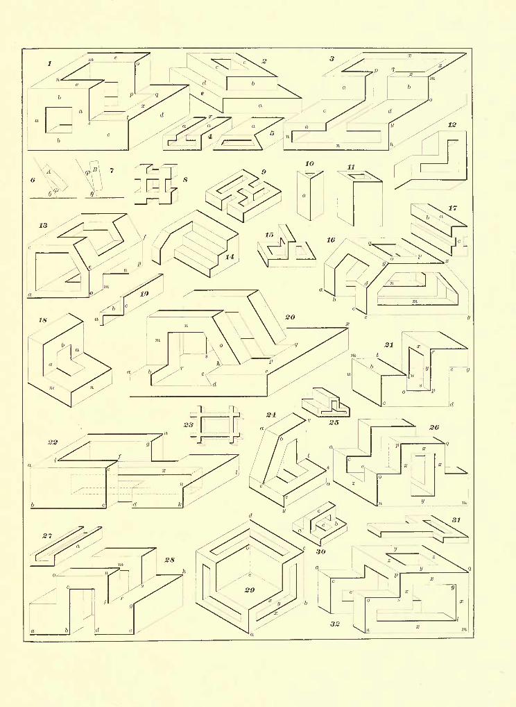
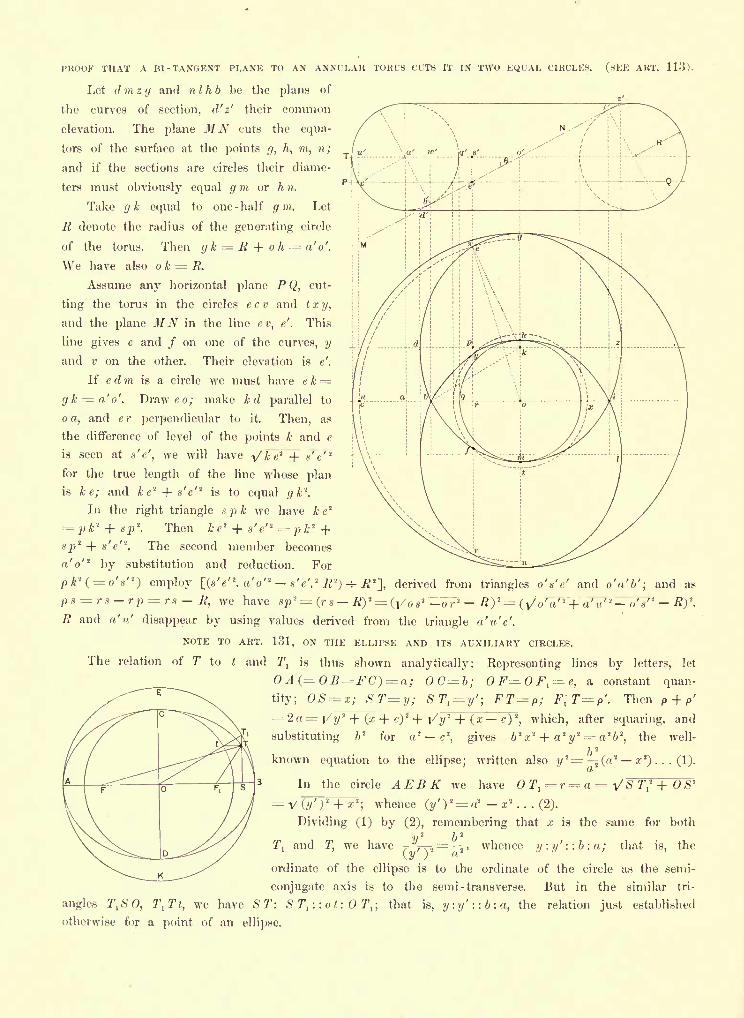
PROOF THAT A HI -TANGENT PLANE TO AN ANNULAR TORUS CUTS IT IN TWO EQUAL CIRCLES. (SEE ART. 113).
Let d m 2 g and nlhb be the plans of
the curves of section, d'z' their common
elevation. The plane MN cuts the equa-
tors of the surface at the points g, h, m, n;
and if the sections are circles their diame-
ters must obviously equal g m or h n.
Take gk equal to one -half g m. Let
R denote the radius of the generating circle
of the torus. Then gk = R + oh = '</.
We have also o k = R.
Assume any horizontal plane P Q, cut-
ting the torus in the circles e c v and t x y,
and the plane MN in the line ev, e'. This
line gives e and / on one of the curves, y
and v on the other. Their elevation is e'.
If e d m is a circle we must have ek =gk = a'o'. Drawee; make k d parallel to
o a, and e r perpendicular to it. Then, as
the difference of level of the points k and e
is seen at s'e', we will have y'Fe'M- s'e'2
for the true length of the line whose plan
is ke; and ke'* + s'e'* is to equal gk'1
.
In the right triangle spk we have k e'2
Then k e2 + s'e"' = p k 2
sp2 + s'e'
a o
The second member becomes
by substitution and reduction. For
pfc*(=o'O employ [(s'e'2. a'o" - s'e'.
2
R'>) -=- R 2
~],derived from triangles o'n'e' and o'a'b'; and as
p8 = rs rp = r8 R, we have sp'L = (r s tf)
2= d/os 2 -or'' R)''= (y'oV 2Ta"'"tt
/T oV 2
#)2
.
^ and V disappear by using values derived from the triangle a'u'c'.
NOTE TO ART. 131, ON THE ELLIPSE AND ITS AUXILIARY CIRCLES.
The relation of T to t and T, is thus shown analytically: Eepresenting lines by letters, let
A(= OB=FC) = ; OC=b; OF=OF1
=c, a constant quan-
tity; OS=x; ST=y; STl=
y'; FT= P ; F[T=?'. Then P + P'
2 = i/ 1/
2 + (z + c)2-f I/?/
2-f- (x c)
2, which, after squaring, and
substituting 62
for2
c\ gives 62x
2 + a 2
i/
2 = n26
2
,the well-
b'1
known equation to the ellipse; written also y*= 2 (a* a;2
) . . . (1).
In the circle AEBK we have OTl= r= a =
';whence (y')
!= a' x 2. . . (2).
T,2 + OS*
= y (?y';2 +
Dividing (1) by (2), remembering that x is the same for both
y2
b2
7", and7',
we have 7-*r\i =; j' whence y: y' ::b: a; that is, the\y ) a
ordinate of the ellipse is to the ordinate of the circle as the semi-
conjugate axis is to the semi - transverse. But in the similar tri-
anglesr
l\SO, l\Tt, we have ST: S T, : : o t : T,; that is, y:y'::b:a, the relation just established
otherwise for a point of an ellipse.
THE NOMENCLATURE AND DOUBLE GENERATION OF TROCHOIDS.
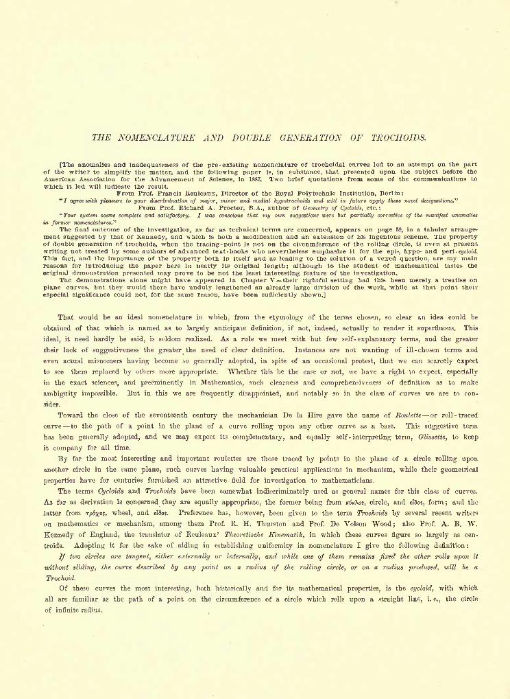
THE NOMENCLATURE AND DOUBLE GENERATION OF TROCHOIDS.
[The anomalies and inadequateness of the pre-existing nomenclature of trochoidal curves led to an attempt on the partof the writer to simplify the matter, and the following paper is, in substance, that presented upon the subject before the
American Association for the Advancement of Science, in 1887. Two brief quotations from some of the communications to
which it led will indicate the result.
From Prof. Francis Reuleaux, Director of the Royal Polytechnic Institution, Berlin:" / agree with pleasure to your discrimination of major, minor and medial hypotrochoids and will in future apply these novel designations."
From Prof. Kichard A. Proctor, B.A., author of Geometry of Cycloids, etc.:" Tour system seems complete and satisfactory. I was conscious that my own suggestions were but partially corrective of the manifest anomalies
in former nomenclatures."
The final outcome of the investigation, as far as technical terms are concerned, appears on page 59, in a tabular arrange-ment suggested by that of Kennedy, and which is both a modification and an extension of his ingenious scheme. The propertyof double generation of troehoids, when the tracing-point is not on the circumference of the rolling circle, is even at presentwriting not treated by some authors of advanced text-books who nevertheless emphasize it for the epi-, hypo- and peri -
cycloid.
This fact, and the importance of the property both in itself and as leading to the solution of a vexed question, are my mainreasons for introducing the paper here in nearly its original length; although to the student of mathematical tastes the
original demonstration presented may prove to be not the least interesting feature of the investigation.The demonstrations alone might have appeared in Chapter V their rightful setting had this been merely a treatise on
plane curves, but they would there have unduly lengthened an already large division of the work, while at that point their
especial significance could not, for the same reason, have been sufficiently shown.]
That would be an ideal nomenclature in which, from the etymology of the terms chosen, so clear an idea could be
obtained of that which is named as to largely anticipate definition, if not, indeed, actually to render it superfluous. This
ideal, it need hardly be said, is seldom realized. As a rule we meet with but few self-explanatory terms, and the greater
their lack of suggest!veness the greater the need of clear definition. Instances are not wanting of ill-chosen terms and
even actual misnomers having become so generally adopted, in spite of an occasional protest, that we can scarcely expect
to see them replaced by others more appropriate. Whether this be the case or not, we have a right to expect, especially
in the exact sciences, and preeminently in Mathematics, such clearness and comprehensiveness of definition as to make
ambiguity impossible. But in this we are frequently disappointed, and notably so in the class of curves we are to con-
sider.
Toward the close of the seventeenth century the mechanician De la Hire gave the name of Roulette or roll -traced
curve to the path of a point in the plane of a curve rolling upon any other curve as a base. This suggestive term
has been generally adopted, and we may expect its complementary, and equally self - interpreting term, Glissette, to keep
it company for all time.
By far the most interesting and important roulettes are those traced by points in the plane of a circle rolling upon
another circle in the same plane, such curves having valuable practical applications in mechanism, while their geometrical
properties have for centuries furnished an attractive field for investigation to mathematicians.
The terms Cycloids and Troehoids have been somewhat indiscriminately used as general names for this class of curves.
As far as derivation is concerned they are equally appropriate, the former being from /ctf/cXos, circle, and eTSos, form;and the
latter from Tp6%o?, wheel, and efSos. Preference has, however, been given to the term Troehoids by several recent writers
on mathematics or mechanism, among them Prof. E. H. Thurston and Prof. De Volson "Wood;
also Prof. A. B. W.
Kennedy of England, the translator of Reuleaux' Theoretische Kinematitc, in which these curves figure so largely as cen-
troids. Adopting it for the sake of aiding in establishing uniformity in nomenclature I give the following definition :
If two circles are tangent, either externally or internally, and while one of them remains fixed the other rolls upon it
without sliding, the curve described by any point on a radius of the rolling circle, or on a radius produced, will be a
Trochoid.
Of these curves the most interesting, both historically and for its mathematical properties, is the cycloid, with which
all are familiar as the path of a point on the circumference of a circle which rolls upon a straight line, i. e., the circle
of infinite radius.
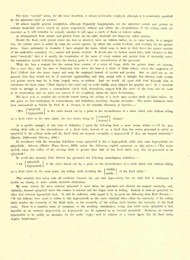
The term "cycloid" alone, for the locus described, is almost universally employed, although it is occasionally qualified
by the adjectives right or common.
Of almost equally general acceptation, although frequently inappropriate, are the adjectives curtate and prolate, to
indicate trochoidal curves traced by points respectively without and within the circumference of the rolling circle (or
generator as it will hereafter be termed) whether it roll upon a circle of finite or infinite radius.
As distinguished from curtate and prolate forms all the other trochoids are frequently called common.
Should the fixed circle (called either the base or director) have an infinite radius, or, in other words, be a straight
line, the curtate curve is called by some the curtate cycloid; by others the curtate trochoid; and similarly for the prolate
forms. Since uniformity is desirable I have adopted the terms which seem to have in their favor the greater number
of the authorities consulted, viz., curtate and prolate trochoid. It should also be further stated here, with reference to this
word "trochoid," that it is usually the termination of the name of every curtate and prolate form of trochoidal curve,
the termination cycloid indicating that the tracing point is on the circumference of the generator.
With the base a straight line the curtate form consists of a series of loops, while the prolate forms are sinuous,
like a wave line;
and the same is frequently true when the base is a circle of finite radius;
hence the suggestion of
Prof. Clifford that the terms looped and wavy be employed instead of curtate and prolate. But we shall see, as we
proceed, that they would not be of universal applicability, and that, except with a straight line director, both curtate
and prolate curves may be, in form, looped, wavy, or neither. And we would all agree with Prof. Kennedy that as
substitutes for these terms "Prof. Cayley's kru-nodal and ac-nodal hardly seem adapted for popular use." It is therefore
futile to attempt to secure a nomenclature which shall, throughout, suggest both the form of the locus and the mode
of its construction, and we must rest content if we completely attain the latter desideratum.
We have next to consider the trochoids traced during the rolling of a circle upon another circle of finite radius. At
this point we find inadequacy in nomenclature, and definitions involving singular anomalies. The earlier definitions have
been summarized as follows by Prof. K. A. Proctor, in his valuable Geometry of Cycloids:
f epicycloid )"The < v is the curve traced out by a point in the circumference of a circle which rolls without sliding:
( hypocycloid j
(external )
on a fixed circle in the same plane, the two circles being in 4 > contact."
( internal j
As a specific example of this class of definition I quote the following from a more recent writer: "If the gen-
erating circle rolls on the circumference of a fixed circle, instead of on a fixed line, the curve generated is called an
epicycloid if the rolling circle and the fixed circle are tangent externally, a hypocycloid if they are tangent internally."
(Byerly, Differential Calculus, 1880.)
In accordance with the foregoing definitions every epicycloid is also a hypocycloid, while only some hypocycloids are
epicycloids. Salmon (Higher Plane Curves, 1879) makes the following explicit statement on this point: "The hypo-
cycloid, when the radius of the moving circle is greater than that of the fixed circle, may also be generated as an
epicycloid."
To avoid any anomaly Prof. Proctor has presented the following unambiguous definition :
( epicycloid )" An !J.
is the curve traced out by a point on the circumference of a circle which rolls without sliding( hypocycloid j
( outside")
on a fixed circle in the same plane, the rolling circle touching the < v of the fixed circle."
( inside j
This certainly does away with all confusion between the epi- and hypo -curves, but we shall find it inadequate to
enable us, clearly, to make certain desirable distinctions.
By some writers the term external epicycloid is used when the generator and director are tangent externally, and,
similarly, internal epicycloid when the contact is internal and the larger circle is rolling. Instead of internal epicycloid we
often find external hypocycloid used. It will be sufficient, with regard to it, to quote the following from Prof. Proctor :
" It has hitherto been usual to define it (the hypocycloid) as the curve obtained when either the convexity of the rolling
circle touches the concavity of the fixed circle, or the concavity of the rolling circle touches the convexity of the fixed
circle. There is a manifest want of symmetry in the resulting classification, seeing that while every epicycloid is thus
regarded as an external hypocycloid, no hypocycloid can be regarded as an internal epicycloid. Moreover, an external
hypocycloid is in reality an anomaly, for the prefix 'hypo,' used in relation to a closed figure like the fixed circle,
implies interiorness."
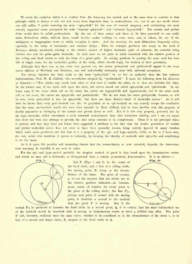
To avoid the confusion which it is evident from the foregoing has existed, and at the same time to conform to that
principle which is always a safe one and never more important than in nomenclature, viz., not to use two words where
one will suffice, I prefer reserving the term "epicycloid
" for the case of external tangency, and substituting the more
recently suggested name pericycloid for both "internal epicycloid" and "external hypocycloid." The curtate and prolate
forms would then be called peritrochoids. By the use of these names and those to be later presented we can easily
make distinctions which, without them, would involve undue verbiage in some cases, and, in others, the use of the
ambiguous or inappropriate terms to which exception is taken. And the necessity for such distinctions frequently arises,
especially in the study of kinematics and machine design. Take, for example, problems like many in the work of
Reuleaux already mentioned, relating to the relative motion of higher kinematic pairs of elements, the centroids being
circular arcs and the point -paths trochoids. In such cases we are quite as much concerned with the relative position of
the rolling and fixed circles as with the form of a point-path. In solving problems in gearing the same need has been
felt of simple terms for the trochoidal profiles of the teeth, which should imply the method of their generation.
Although they have not, as yet, come into general use, the names pericycloid and peritrochoid appear in the more
recent editions of Weisbach and Reuleaux, and will undoubtedly eventually meet with universal acceptance.
Yet strong objection has been made to the term "pericycloid
"by no less an authority than the late eminent
mathematician, Prof. W. K. Clifford, who nevertheless adopted the "peritrochoid." I quote the following from his Elements
of Dynamic: "Two circles may touch each other so that each is outside the other, or so that one includes the other.
In the former case, if one circle rolls upon the other, the curves traced are called epicycloids and epitrochoids. In the
latter case, if the inner circle roll on the outer, the curves are hypocycloids and hypotrochoids, but if the outer circle
roll on the inner, the curves are epicycloids and peritrochoids. We do not want the name pericycloids, because, as will
be seen, every pericycloid is also an epicycloid; but there are three distinct kinds of trochoidal curves." As it will
later be shown that every peri- trochoid can also he generated as an epi -trochoid we can scarcely escape the conclusion
that the name peritrochoid would also have been rejected by Prof. Clifford, had he been familiar with this property of
double generation as belonging to the curtate and prolate forms as well. But it is this very property, possessed also bythe hypo- trochoids, which necessitates a more extended nomenclature than that heretofore existing, and I am not aware
that there has been any attempt to provide the nine terms essential to its completeness. These it is my principal object
to present, and that they have not before been suggested I attribute to the fact that the double generation of curtate
and prolate trochoidal curves does not seem to have been generally known, being entirely ignored in many treatises
which make quite prominent the fact that it is a property of the epi- and hypo -cycloids, while, as far as I have seen,
the only writer who mentions it proves it indirectly, by showing the identity of trochoids with epicyclics and establishing
it for the latter.
As it is upon this peculiar and interesting feature that the nomenclature, as now extended, depends, the demonstra-
tions necessary to establish it are next in order.
For the epi- and hypo -cycloid probably the simplest method of proof is that based upon the instantaneous centre,
and which we may call a kinematic, as distinguished from a strictly geometrical, demonstration. It is as follows :
Let F (Figs. 1 and 2) be the centre of
the fixed circle, and r that of a rolling circle,
the tracing point, P, being on the circum-
ference of the latter. The point of contact,
g, is at the moment that the circles are in
the relative position indicated an instanta-
neous centre of rotation for every point in
the plane of the rolling circle; the line Py,
joining such point of contact with the tracing
point, is therefore a normal to the trochoid
that the point P is tracing. But if the
normal Py be produced to intersect the fixed circle in a second point, Q, it is evident that the same infinitesimal arc
of the trochoid would be described with Q serving as instantaneous centre as when q fulfilled that office. The point
P will, therefore, evidently trace the same curve, whether it be considered as in the circumference of the circle r, or in
that of a second and larger circle, R, tangent to the fixed circle at Q.
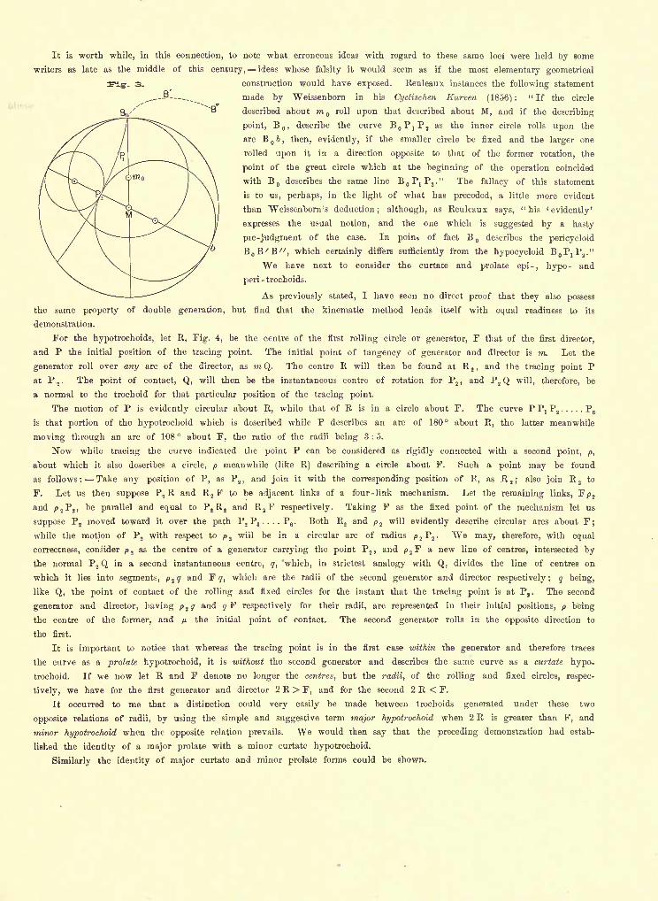
It is worth while, in this connection, to note what erroneous ideas with regard to these same loci were held by some
writers as late as the middle of this century, ideas whose falsity it would seem as if the most elementary geometrical
construction would have exposed. Reuleaux instances the following statement
made by "Weissenborn in his Cyclischen Kurven (1856) :" If the circle
described about m aroll upon that described about M, and if the describing
point, B,
describe the curve as the inner circle rolls upon the
arc B i, then, evidently, if the smaller circle be fixed and the larger one
rolled upon it in a direction opposite to that of the former rotation, the
point of the great circle which at the beginning of the operation coincided
with B describes the same line BoPjPj." The fallacy of this statement
is to us, perhaps, in the light of what has preceded, a little more evident
than "Weissenborn 's deduction; although, as Reuleaux says, "his '
evidently'
expresses the usual notion, and the one which is suggested by a hasty
pre-judgment of the case. In point of fact B describes the pericycloid
BoE'E", which certainly differs sufficiently from the hypocycloid B,,?!?.,."
We have next to consider the curtate and prolate epi-, hypo- and
peri- trochoids.
As previously stated, I have seen no direct proof that they also possess
the same property of double generation, but find that the kinematic method lends itself with equal readiness to its
demonstration.
For the hypotrochoids, let R, Fig. 4, be the centre of the first rolling circle or generator, F that of the first director,
and P the initial position of the tracing point. The initial point of tangency of generator and director is m. Let the
generator roll over any arc of the director, as m Q. The centre R will then be found at E,, and the tracing point P
at P2
. The point of contact, Q, will then be the instantaneous centre of rotation for P2 ,
and P2 Q will, therefore, be
a normal to the trochoid for that particular position of the tracing point.
The motion of P is evidently circular about R, while that of R is in a circle about F. The curve P P, P2..... P
6
is that portion of the hypotrochoid which is described while P describes an arc of 180 about R, the latter meanwhile
moving through an arc of 108 about F, the ratio of the radii being 3:5.
Now while tracing the curve indicated the point P can be considered as rigidly connected with a second point, p,
about which it also describes a circle, p meanwhile (like R) describing a circle about F. Such a point may be found
as follows: Take any position of P, as P2 ,
and join it with the corresponding position of R, as R 2 ;also join R
2 to
F. Let us then suppose P2R and R
2F to be adjacent links of a four-link mechanism. Let the remaining links, Fp 2
and p 2P
2 ,be parallel and equal to P
2R
2and R
2F respectively. Taking F as the fixed point of the mechanism let us
suppose P2moved toward it over the path P
2P
3. . . . P
6. Both R
2and p 2
will evidently describe circular arcs about F;
while the motion of P2with respect to p 2
will be in a circular arc of radius p 2P
2. We may, therefore, with equal
correctness, consider p 2as the centre of a generator carrying the point P
2 ,and p 2
F a new line of centres, intersected by
the normal P2 Q in a second instantaneous centre, g, 'which, in strictest analogy with Q, divides the line of centres on
which it lies into segments, p 2 q and F q, which are the radii of the second generator and director respectively; q being,
like Q, the point of contact of the rolling and fixed circles for the instant that the tracing point is at P, . The second
generator and director, having p ^ q and qF respectively for their radii, are represented in their initial positions, p being
the centre of the former, and p. the initial point of contact. The second generator rolls in the opposite direction to
the first.
It is important to notice that whereas the tracing point is in the first case within the generator and therefore traces
the curve as a prolate hypotrochoid, it is without the second generator and describes the same curve as a curtate hypo-
trochoid. If we now let R and F denote no longer the centres, but the radii, of the rolling and fixed circles, respec-
tively, we have for the first generator and director 2 R > F, and for the second 2 R < F.
It occurred to me that a distinction could very easily be made between trochoids generated under these two
opposite relations of radii, by using the simple and suggestive term major hypotrochoid when 2 R is greater than F, and
minor hypotrochoid when the opposite relation prevails. We would then say that the preceding demonstration had estab-
lished the identity of a major prolate with a minor curtate hypotrochoid.
Similarly the identity of major curtate and minor prolate forms could be shown.
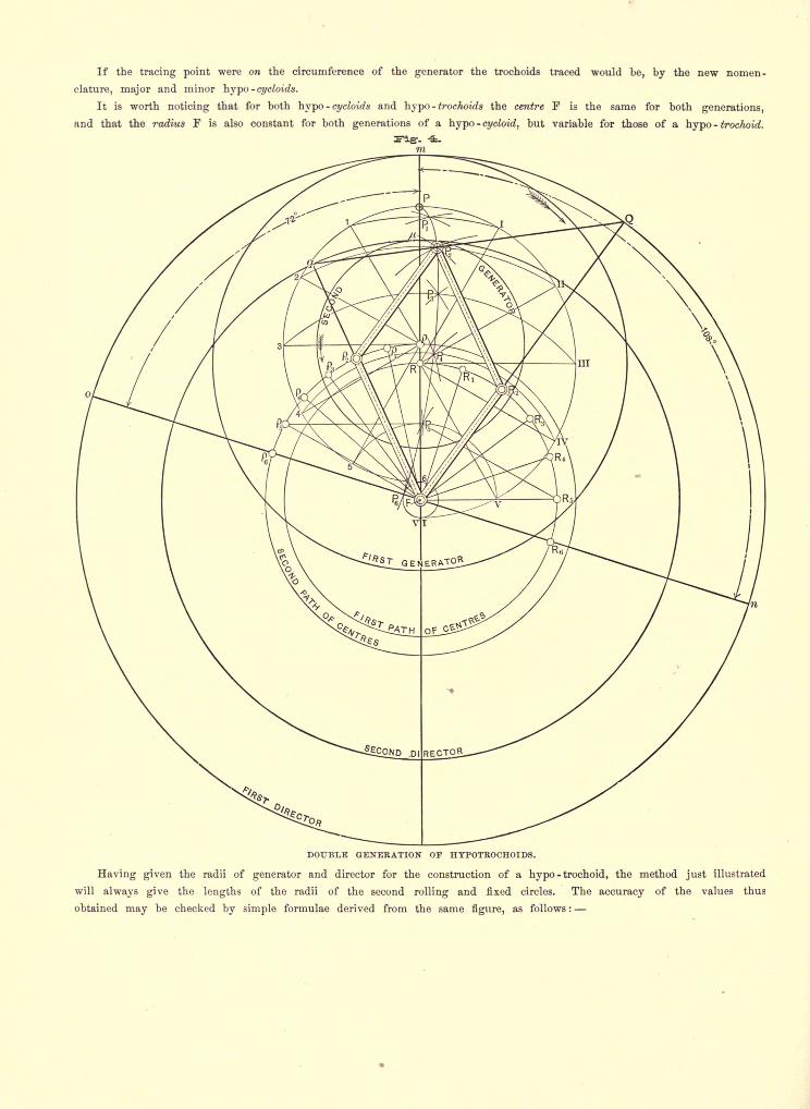
If the tracing point were on the circumference of the generator the trochoids traced would be, by the new nomen-
clature, major and minor \\ypo-cycloids.
It is worth noticing that for both hypo -cycloids and hypo - trochoids the centre F is the same for both generations,
and that the radius f is also constant for both generations of a hypo -cycloid, but variable for those of a hypo- trochoid.
DOUBLE GENERATION OP HTPOTROCHOIDS.
Having given the radii of generator and director for the construction of a hypo - trochoid, the method just illustrated
will always give the lengths of the radii of the second rolling and fixed circles. The accuracy of the values thus
obtained may be checked by simple formulae derived from the same figure, as follows :
Radii being given for generation as a major hypotrochoid, to find corresponding values for the identical minor hypo-
trochoid.
Let Ft
denote the radius F Q [= F m ] of the first director.
" Fs
' " " Fy [=FM ]" " second "
" r " " " R2 Q [
= Rm] " " first generator.
"p
" " "p 2 g [= pfn ]
" " second "
" tr " "tracing radius of the first generation, i. e., the distance R
2P
2 (or R P) of
tracing point from centre of first generator.
Let t p equal the second tracing radius = p 2P
2= p P.
From the similar triangles Q F q and Q R 2P
2we have F, : F, : : tr : r
F. (tr)whence F
2= ' v
, (1)r
F, (tr) ( F, )also p = F
2tr = - - tr = tr
\1 I (2)
r ( r )
and tp = p 2P
2= FRj = d, the distance between the centers of first generator and director (3)
If the radii be given for a minor hypotrochoid then FQ : p 2 P, : : Fy : p 2 y,
from which we have, as before,
radius of given fixed circle X given tracing radiusfixed radius desired = :
(4)radius of given generator
and, similarly, formulae (2) and (3) give the radius of desired generator and the corresponding tracing radius.
With the tracing point on the circumference of the generator, if we let R = radius of the latter for a major hypo-
cycloid and r correspondingly for the minor curve, then
for a major hypocycloid R = F ? (5)
" a minor " r = F R (6)
For the curves intermediate between the major and minor hypotrochoids, viz., those traced when the diameter of the
rolling circle is exactly half that of the fixed circle, a separate division seems essential to completeness, and for such I
suggest the general name of medial hypotrochoids. For these the formulae for double generation are the same as for
the "major" and "minor" curves, and similarly derived.
With the tracing point ore the circumference of the generator these curves reduce to straight lines, diameters of the
director. In all other cases the medial hypotrochoids are an interesting exception to what we might naturally expect,
being neither looped nor wavy, but ellipses. The failure of the terms "looped" and "wavy" to apply to these medial
curves is paralleled by that of the adjectives "curtate" and "prolate," since, contrary to the signification of the latter
terms, any ellipse generated as a curtate curve is larger than the largest prolate elliptical hypotrochoid having the same
director. And as we have seen that, with scarcely an exception," curtate " and "
prolate"
apply equally to the same
curve, our only reason for retaining them is the fact of their general acceptation as indicative of the location of the
tracing point with respect to the circumference of the rolling circle.
Since the medial hypotrochoids are either straight lines or ellipses, we can readily find for them that which we have
found it useless to attempt to construct for the other trochoidal curves, viz., simple terms suggestive of their form; in
fact the names "straight hypocycloid" and "elliptical hypotrochoid" have long been familiar to us all, and we have
but to incorporate them into the nomenclature we are constructing.
It only remains to show that a prolate epi- trochoid can be generated as a curtate peri- trochoid, and vice versa, for
which the demonstration is analogous to that given for the hypo-curves and leads to the following formulae, derived
from the similar triangles QF<? and QRjP, (the values being supposed to be given for the epi-trochoid and desired for
the peri -trochoid) :
= F,_(*r) _ (7)r
p = trJ ^ + 1
J(8)
tp = d = distance between centres of given generator and director = F, + r (9)
If given as a peri- trochoid and desired as an epi- trochoid the tracing radius will again equal the distance between the
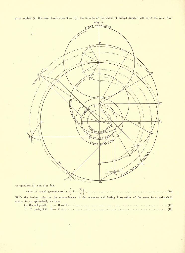
given centres (in this case, however = R F) ;the formula of the radius of desired director will be of the same form
as equations (1) and (7) ;but
radius of second generator = tr \ 1 - -I (10)
With the tracing point on the circumference of the generator, and letting K = radius of the same for a peritrochoid
and r for an epitrochoid, we have
for the epicycloid r = R F(11)
" "pericycloid R= F + r , (12)
ALPHABETS AND ORNAMENTAL DEVICES FOR TITLES.
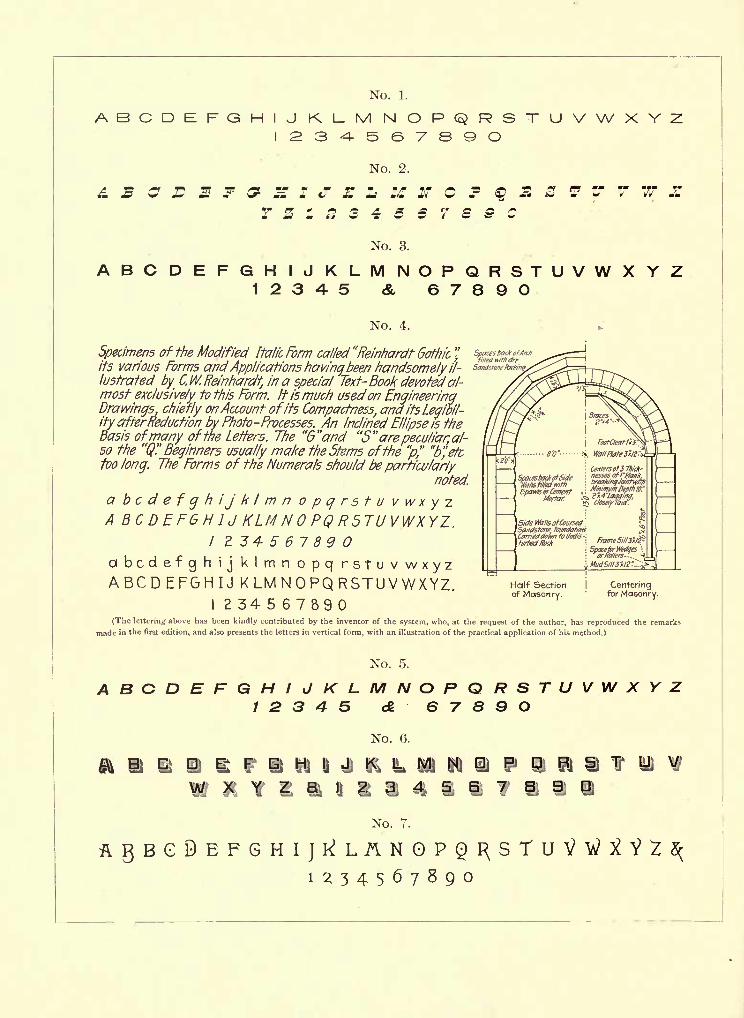
ABCDEFG
& s a L
No. 1.
HIJ KLM NOPQRSI2345678QO UVWXY
No. 2.
z L M c p z 3 T w s
No. 3.
ABCDEFGHIJKLMNOPQRSTUVW1234-5 & 6789O
XYZ
No. 4.
Specimens of the Modified Italic Form called "Reinhardt Gothic"
its various Forms and Applications havinqbeen handsomely il-
lustrated by C.W. Reinhardt, in a special Text- Book devoted al-most exclusively to this Form. It ismuch usedon EngineeringDrawings, chiefjy onAccount ofits Compactness, and its Legibil-
ity afterReduction byPhoto-Processes. An Inclined Ellipse is the
Basis ofmany ofthe Lefters. The "G"and "5"arepeculiar, al-so the "Q" Beginners usually make the Stems ofthe "p" b"efctoo long. The Forms of the Numerals should be particularly
noted.
a bcdefghijk/mn o p q r s t u v w x y z
A BC DEFGH IJ KLM NO PQ R5TUVWXYZ.I 234567890
abcdefgh ij klmn opq rstuvwxyzA BCD EFGH IJ K LM N OPQ RSTU V WXYZ. Half Section I Centering
of Masonry.'
for Masonry.
I 234567890(The lettering above has been kindly contributed by the inventor of the system, who, at the request of the author, has reproduced the remarks
made in the first edition, and also presents the letters in vertical form, with an illustration of the practical application of his method.)
ABCDEFNo. 5.
GHIJKLMNOPQRSTUVWXYZ12345 A 67890
No. 6.
PQRBYUV1 1 1
NO. r.
1^34567890
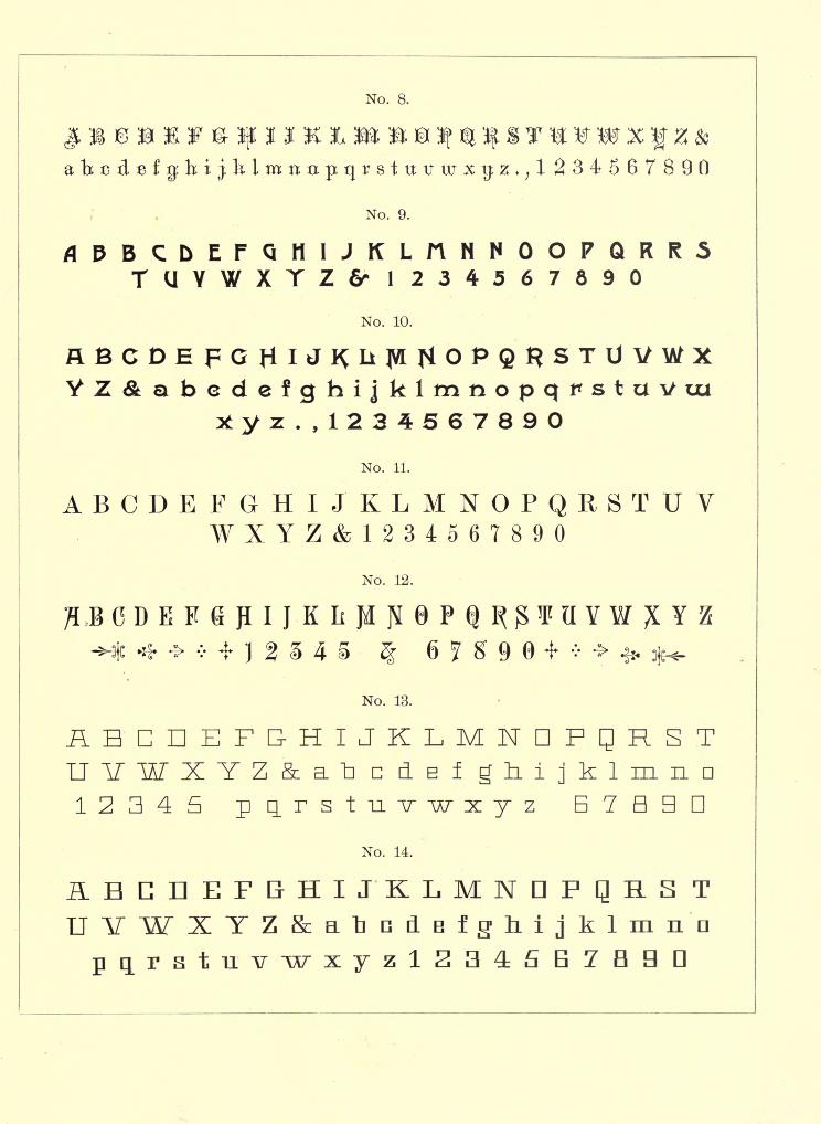
No. 8.
, ,1234567 8 90
No. 9.
flDBCDEFQHIJKLnNNOOPQRRSTUYWXTZ6" 1 234567890
No. 10.
YZ&abedefghijklmnopqrstavuu*yz., 1234567890
No. 11.
ABODE FGHIJ'KLMNOPQRSTUVWXYZ&1234567890
No. 12.
* * + ] % 3 4 5
No. 13.
AHCnEFG-HIJKLMNDPQRSTUVlATXYZ&ia^ c d B f gliijklmnn12345 ptirstuvwxyz 67890
No. 14.
ABCHEF&HIJKLMNDFqHSTUVWXYZ&aliGiiBfg'liijklinna
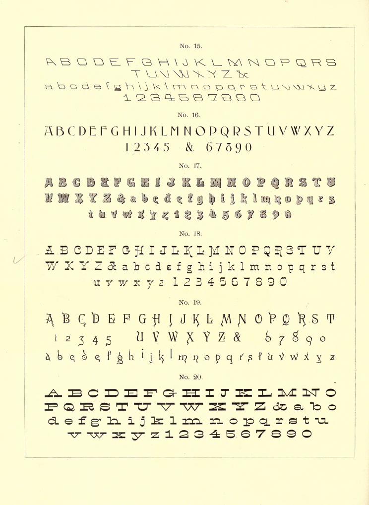
No. 15.
oT
\z> o <d
No. 16.
ABCDEFGHIJKLMNOPQRSTUVWXYZI 2345 & 67590
No. 17.
i j It "1
No. 18.
1234567890No. 19.
No. 20.
Q R S T "CT TT T77"
e f gr li. i j 3s 1 ZICL
To o
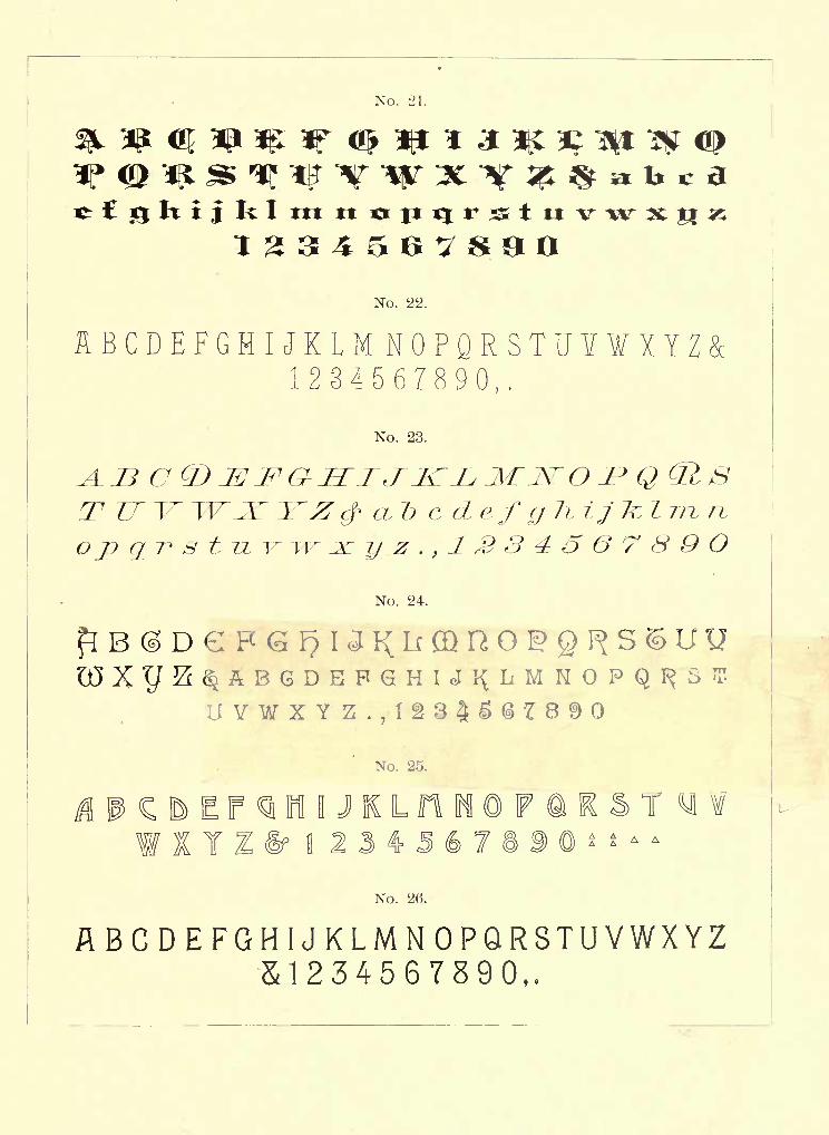
ttt tt
1234567800No. 22.
HBCDEFGMIJKLMNOPQRSTUYXYZ1234567890,
No. 23.
Top
T
cdef
No. 24.
No. 25.
I JKL
No. 26.
8 9 A AA A
n
"U-
A A
ABCDEFGHIJKLMNOPQRSTUVWXYZ&1234567890,
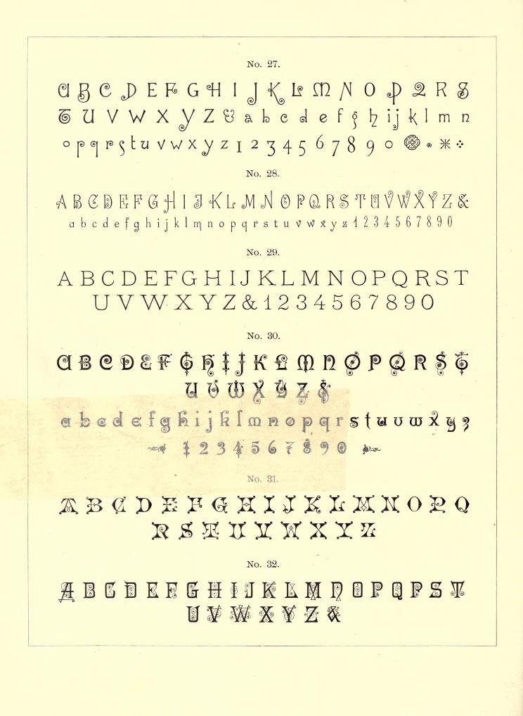
U"
V W X :Z
No. 27.
1 4^ I<? CD AI D J R &TV 1A AIZ / N v/ isL/ c^Ci IV (fjQ) \> I
^Lcdef^bijklmnj ^ y
2 7 4 r 6yR Q o @> . )K -
J I j / w
No. 28.
abcdefc]hijklrr|nopc|rstuVW*yz4234567o90
No. 29.
ABODE FGHIJKLMNOPQRSTUV\VXYZ&1234567890
No. 30.
(sR
sbedefgfiijK2 3 ^' 5
No. 31.
No. 32.
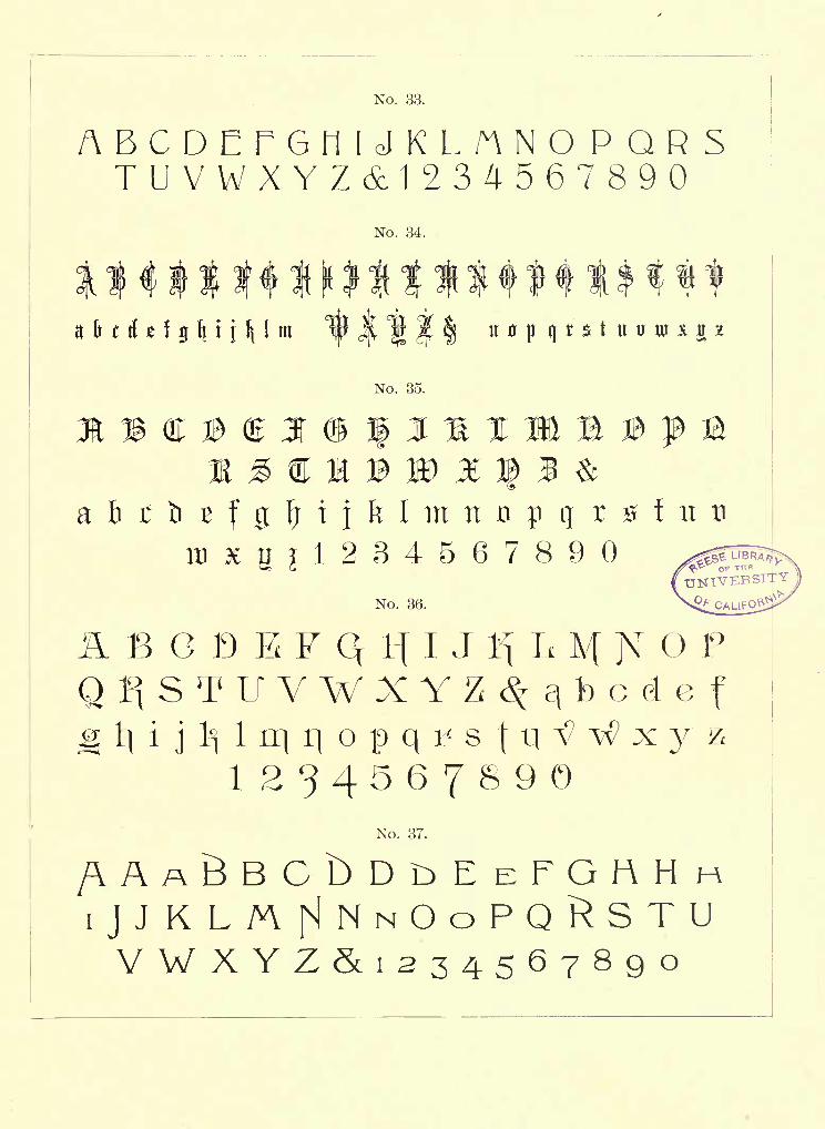
No. 33.
ABCDErGMUKLnNOPQRSTUVWXYZ&1234567890
No. 34.
a fr t d 1 1 \ \\ \ 1 m
/
n p qr$t uu
No. 35.
No. 36.
6 C D E F Q tf IJ 1^ L M N O P
Q^STUVWXYZ^-qbcdefg 1} i
jI1
)1 rq i] o p q v s \ \\ rf ^ x y &
No. 37.
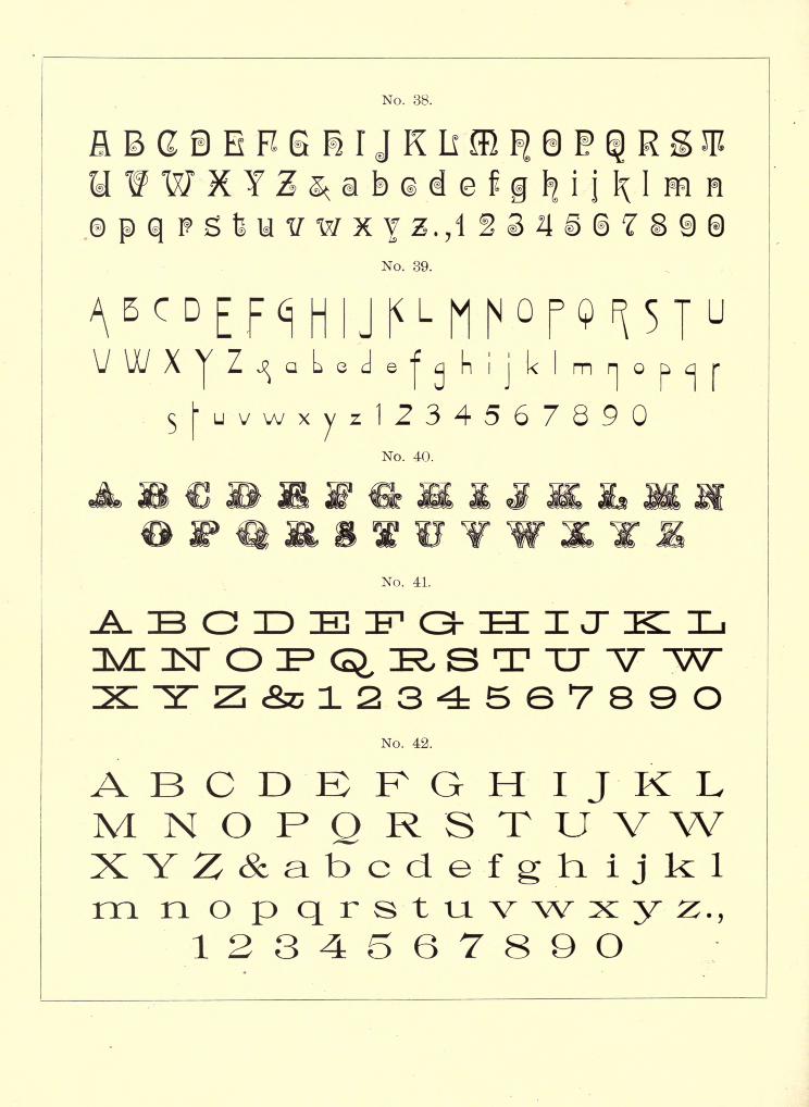
No. 38.
No. 39.
X abed h i
j
k
No. 40.
No. 41.
Z&C123456789ONo. 42.
ABCDEFGHIJKLM NOPQRSTUVWXYZ&abcdefghijklm n o p qrstuvwxyz.,1234567890
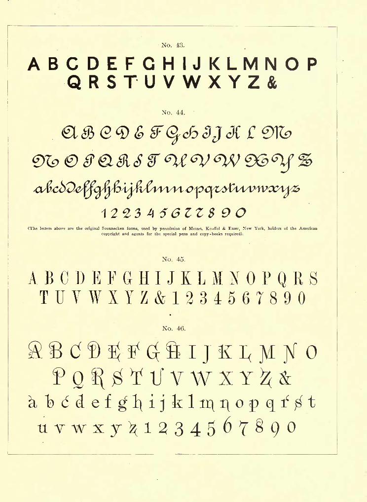
No. 43.
ABCDEFGHIJKLMNOPQRSTUVWXYZ&
No. 44.
e c
56ZZS 9OCThe letters above are the original Soennecken forms, used by permission of Messrs. Keuffel & Esser, New York, holders of the American
copyright and agents for the special pens and copy-books required).
No. 45.
ABCDEFGHIJKLMNOPQRSTUVWXYZ&1234567890
No. 46.
Q f\ g If V W X Y
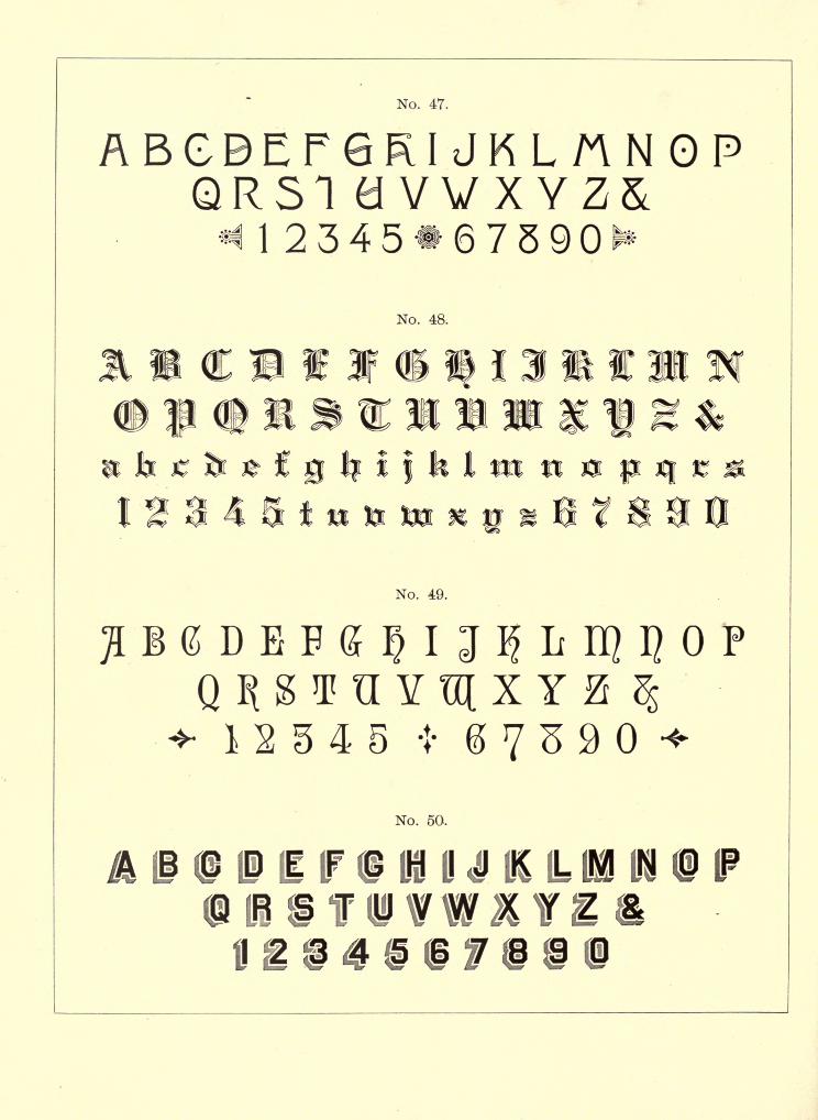
No. 47.
ABGBEFRSI
* 1 2 3 4 5
I JKLMNOPVV XYZ&I67590N
I
No. 48.
No. 49.
No. 50.
I IF ( LH! fl 41 K
ii i i H
IP
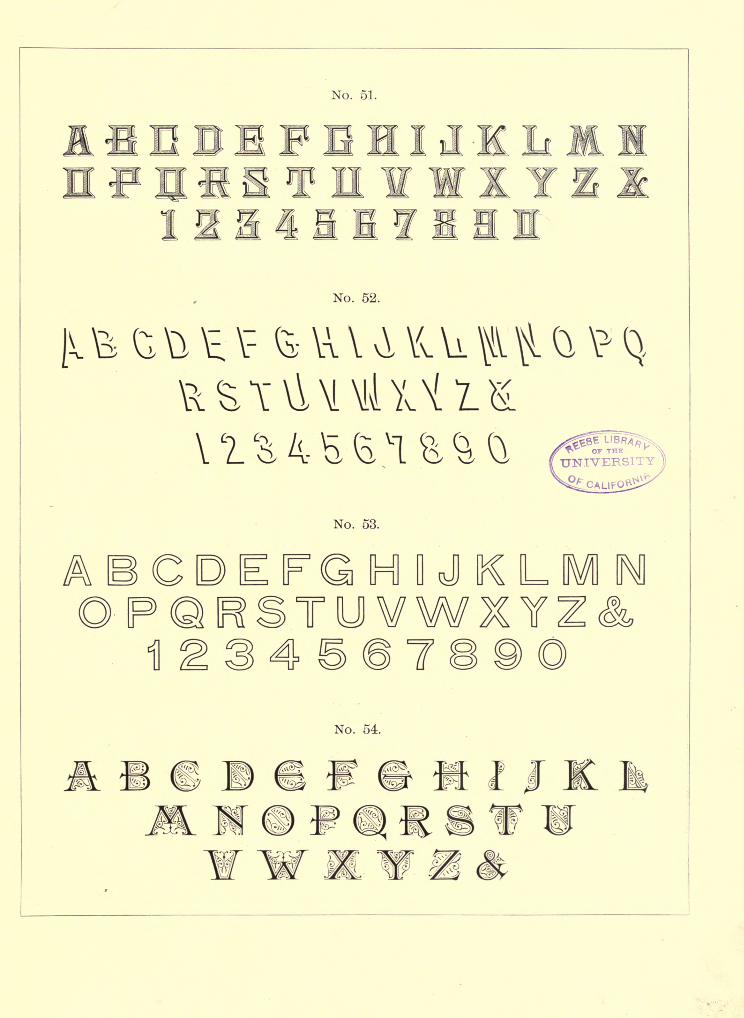
No. 51.
No. 52.
No. 53.
H D JT
LY
7
No. 54.
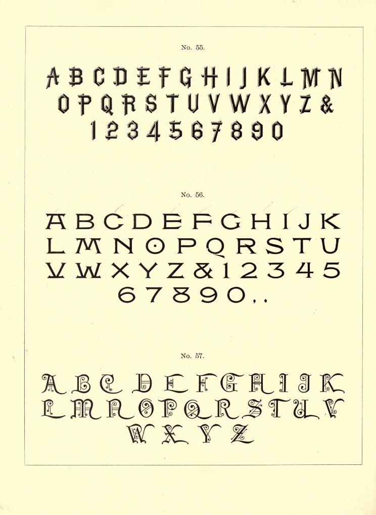
No. 55.
T
No. 56.
KBCDEFGHIJKL-MNOPQRSTUVWXYZ&1234-5
6 T 5 9 O,.
No. 57.
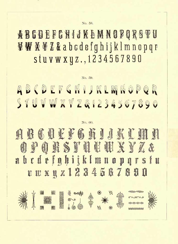
No. 58.
T to
iillabcdBfghijklmnopqrstuvwxijz. ,1234367890
No. 59.
No. 60.
t
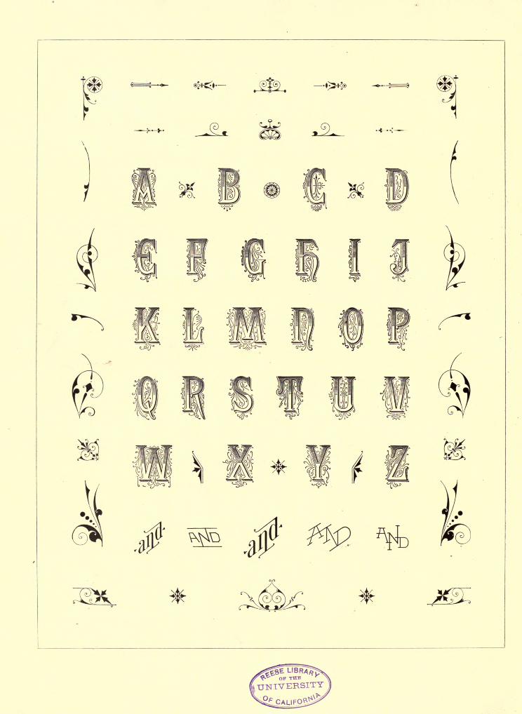
^~~s J
AN imn*Ha,2UVSSWII-*- II __ rtK]
DAY AND TO SLOO ON
NOV f
OCT 22 1946
LD21-50m-8,'32
01975
UNIVERSITY OF CALIFORNIA LIBRARY