Modelling the deep drawing of a 3D woven fabric with a ...
19
HAL Id: hal-01719711 https://hal.archives-ouvertes.fr/hal-01719711 Submitted on 28 Feb 2018 HAL is a multi-disciplinary open access archive for the deposit and dissemination of sci- entific research documents, whether they are pub- lished or not. The documents may come from teaching and research institutions in France or abroad, or from public or private research centers. L’archive ouverte pluridisciplinaire HAL, est destinée au dépôt et à la diffusion de documents scientifiques de niveau recherche, publiés ou non, émanant des établissements d’enseignement et de recherche français ou étrangers, des laboratoires publics ou privés. Modelling the deep drawing of a 3D woven fabric with a second gradient model Gabriele Barbagallo, Angela Madeo, Fabrice Morestin, Philippe Boisse To cite this version: Gabriele Barbagallo, Angela Madeo, Fabrice Morestin, Philippe Boisse. Modelling the deep drawing of a 3D woven fabric with a second gradient model. Mathematics and Mechanics of Solids, SAGE Publications, 2017, 22 (11), pp.2165 - 2179. 10.1177/1081286516663999. hal-01719711
-
Upload
khangminh22 -
Category
Documents
-
view
0 -
download
0
Transcript of Modelling the deep drawing of a 3D woven fabric with a ...
HAL Id: hal-01719711https://hal.archives-ouvertes.fr/hal-01719711
Submitted on 28 Feb 2018
HAL is a multi-disciplinary open accessarchive for the deposit and dissemination of sci-entific research documents, whether they are pub-lished or not. The documents may come fromteaching and research institutions in France orabroad, or from public or private research centers.
L’archive ouverte pluridisciplinaire HAL, estdestinée au dépôt et à la diffusion de documentsscientifiques de niveau recherche, publiés ou non,émanant des établissements d’enseignement et derecherche français ou étrangers, des laboratoirespublics ou privés.
Modelling the deep drawing of a 3D woven fabric with asecond gradient model
Gabriele Barbagallo, Angela Madeo, Fabrice Morestin, Philippe Boisse
To cite this version:Gabriele Barbagallo, Angela Madeo, Fabrice Morestin, Philippe Boisse. Modelling the deep drawingof a 3D woven fabric with a second gradient model. Mathematics and Mechanics of Solids, SAGEPublications, 2017, 22 (11), pp.2165 - 2179. 10.1177/1081286516663999. hal-01719711
Modeling the deep drawing of a 3D woven fabric with a secondgradient model
Gabriele Barbagallo1 and Angela Madeo2 and Fabrice Morestin3 and Philippe Boisse4
March 3, 2017Abstract
Experimental testing on dry woven fabrics exhibits a complex set of evidences that are difficult tobe completely described using classical continuum models. The aim of this paper is to show how theintroduction of energy terms related to the micro-deformation mechanisms of the fabric, in particularto the bending stiffness of the yarns, helps in the modeling of the mechanical behavior of this kindof materials. To this aim, a second gradient, hyperelastic, initially orthotropic continuum theory isproposed to model fibrous composite interlocks at finite strains. In particular, the present work exploresthe relationship between the onset of wrinkling appearing during the simulation of the deep drawing of awoven fabric and the use of a second gradient model. It is shown that the introduction of second gradientterms accounting for the description of in-plane and out-of-plane bending rigidities, decreases the onsetof wrinkles during the simulation of deep-drawing.
In this work, a quadratic energy, roughly proportional to the square of the curvature of the fibers, ispresented and implemented in the simulations. This simple constitutive assumption allows to clearly showthe effects of the second gradient energy on both the wrinkling description and the numerical stabilityof the model. The results obtained in second gradient simulations are descriptive of the experimentalevidence of deep drawing whose description is targeted in this work. The present paper provides additionalevidence of the fact that first gradient continuum theories alone cannot be considered fully descriptive ofthe behavior of dry woven composite reinforcements. On the other hand, the proposed second gradientmodel for fibrous composite reinforcements opens the way both to the more accurate simulation of complexforming processes and to the possibility of controlling the onset of wrinkles.
Contents
1 Introduction 2
2 Second gradient 3D modeling of the deep drawing 32.1 Second gradient modeling . . . . . . . . . . . . . . . . . . . . . . . . . . . . . . . . . . . . . . 42.2 Hyperelastic initially orthotropic first gradient strain energy density . . . . . . . . . . . . . . 52.3 Hyperelastic orthotropic second gradient strain energy density . . . . . . . . . . . . . . . . . . 6
3 Numerical model and results 73.1 Modeling geometry and contact interaction between the mold and the reinforcement . . . . . 83.2 Augmented continuity shape functions . . . . . . . . . . . . . . . . . . . . . . . . . . . . . . . 93.3 Influence of the second gradient on the wrinkling . . . . . . . . . . . . . . . . . . . . . . . . . 103.4 Some considerations concerning mesh-dependency of the performed simulations . . . . . . . . 12
3.4.1 First gradient model with linear shape functions . . . . . . . . . . . . . . . . . . . . . 123.4.2 First and second gradient models with augmented continuity shape functionss . . . . . 133.4.3 Influence of cutting the corners on the onset of wrinkling for first and second gradient
solutions . . . . . . . . . . . . . . . . . . . . . . . . . . . . . . . . . . . . . . . . . . . . 14
4 Conclusions 15
5 References 161Gabriele Barbagallo, [email protected], LaMCoS-CNRS & LGCIE, INSA-Lyon, Universitité de Lyon, 20
avenue Albert Einstein, 69621, Villeurbanne cedex, France2Angela Madeo, corresponding author, [email protected], LGCIE, INSA-Lyon, Université de Lyon, 20 avenue Albert
Einstein, 69621, Villeurbanne cedex and IUF, Institut universitaire de France, 1 rue Descartes, 75231 Paris Cedex 05, France3Fabrice Morestin, [email protected], LaMCoS-CNRS, INSA-Lyon, Universitité de Lyon, 20 avenue Albert Ein-
stein, 69621, Villeurbanne cedex, France4Philippe Boisse, [email protected], LaMCoS-CNRS, INSA-Lyon, Universitité de Lyon, 20 avenue Albert Einstein,
69621, Villeurbanne cedex, France
1
1 IntroductionComposite materials may possess very good characteristics due to the fact that they are obtained assemblingtwo or more constituent materials. This kind of architectured materials can be optimized to obtain excellentresulting properties such as high strength, lightness, cost-effectiveness, thermal and electrical conductivity,insulation and many others.
In particular, the fibrous composite materials are a class of composites that is manufactured using strongfibers aligned in unidirectional sheets, non-crimped fabrics or woven fabrics (bidirectional), impregnatedwith a thermoset or thermoplastic resin. Woven composite materials are the most widespread choice in thecase of mechanical reinforcement, due to their great formability and the subsequent possibility of designingrather complex mechanical pieces. The forming processes, such as the Resin Transfer Moulding, (RTM), havereceived a great deal of attention in the literature (see e.g. [46, 50, 52]). The most current forming processesconsists basically of two stages:
• the dry woven fabric is preformed to obtain the desired geometry for the final part
• a thermoset resin is injected into the woven fabrics filling the pores of the fibrous reinforcement.
The process used in the forming stage is thus followed by the injection and curing of a resin in the wovenfabrics, after which the finished material, union of the reinforcement and the matrix, is obtained. The qualityof the obtained piece is greatly influenced by several factors, such as the characteristics of the preformedwoven fabric and, in particular, its permeability, the characteristic of the resin and the temperature at whichthe injection process takes place. In the literature, it is possible to find a great number of articles studyingin detail the injection processes and the characteristic of the resins (see [46, 50, 52]) and also the preformingprocesses of thin woven reinforcements (see [11, 8, 9, 10, 13, 18, 19, 28, 31, 59, 60]). Nonetheless, few researchwork concern 3D composite reinforcement forming simulation [15, 38, 47]. The focus of this paper will be onthe first stage of the forming process, namely the preforming of 3D dry reinforcements. The understanding ofthis step is very important to determine if the preforming process is even possible. Indeed, the woven fabricscan withstand only a certain amount of shear deformation between the fibers without dissociating and anaccurate modeling thus becomes crucial for optimal design.
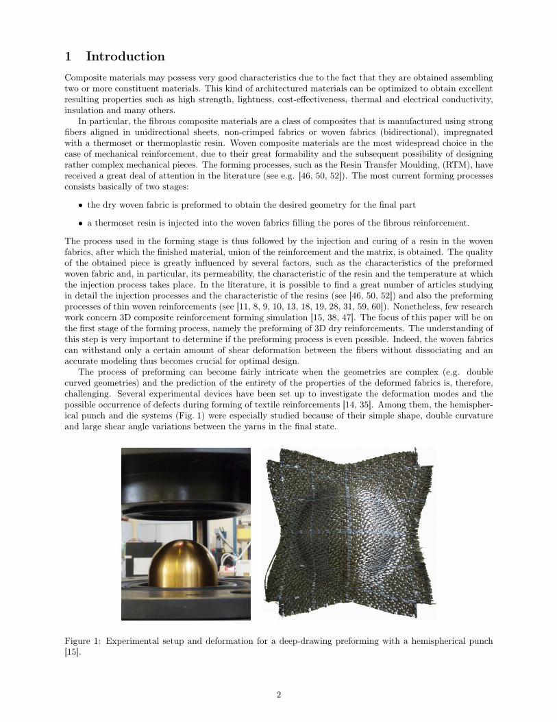
The process of preforming can become fairly intricate when the geometries are complex (e.g. doublecurved geometries) and the prediction of the entirety of the properties of the deformed fabrics is, therefore,challenging. Several experimental devices have been set up to investigate the deformation modes and thepossible occurrence of defects during forming of textile reinforcements [14, 35]. Among them, the hemispher-ical punch and die systems (Fig. 1) were especially studied because of their simple shape, double curvatureand large shear angle variations between the yarns in the final state.
Figure 1: Experimental setup and deformation for a deep-drawing preforming with a hemispherical punch[15].
2
Reliable models for the preforming process should include information about the fiber directions anddensities in the deformed state, so aiding the simulation of the resin injection and of the structural behaviorof the final composite part. Indeed, the permeability of the 3D interlock fabric is strongly influenced by somedeformation states that can alter or even close the interstices in the micro-structure affecting profoundly theresulting material properties. Furthermore, the direction and positioning of the yarns, that are determinedsolely by the preforming process, have a predominant role in the resulting mechanical properties of thecomposite structure (stiffness, damage and fracture, etc.).
Different approaches have been proposed to model the raw fibrous composite materials that can befound in the literature (see [8, 10, 13, 18, 19, 28, 31]). The most widespread approach to the simulation offibrous composite materials is, nowadays, the finite element model that needs the determination of specificconstitutive laws, to be able to describe the complex experimental evidences shown by woven composites.The interest of using second gradient theories for the more realistic description of the mechanical behavior offibrous composite reinforcements has already been established in previous contributions (see [6, 27, 36, 37]).
In the present paper, additional evidence is provided regarding the fact that neglecting the bendingrigidities of the yarns in the modeling phase can produce inaccurate results of the simulation of 3D wovenfabrics (thickness ∼1 cm) during the modeling phase. In order to support this statement, a 3D FEM isimplemented and a rather simple constitutive form of the strain energy density is introduced, accounting for:
1. initial orthotropy,
2. geometric non-linearities,
3. in-plane and out-of-plane bending of the yarns (through the introduction of suitable second gradientterms).
This second gradient model is implemented in COMSOLr looking for solutions that are continuous, as it isusual in FEM, but that also grant continuity of the first derivatives of the displacement field.
In this way, the following desirable results are obtained:
• the solution is in agreement with the observed experimental shapes (Fig. 1),
• the second gradient energy has a beneficial effect on the mesh-dependency of the solution,
• the presence of suitable second gradient terms which are descriptive of the yarns’ bending allows tocontrol the onset and evolution of wrinkles during the deep-drawing process. More particularly, if thesecond gradient parameter (viz the bending stiffness of the yarns) is sufficiently high, no wrinkling is ob-served during the simulation. This result is in agreement with the common observations of experimentalresults.
The results presented in this paper should be used as a guide towards the throughout implementationof FEM codes including second gradient constitutive laws for the complete modeling of the mechanicalbehavior of fibrous composite reinforcements during their forming process.
2 Second gradient 3D modeling of the deep drawingThe description of woven composites’ mechanical behavior demands important efforts. Through the analysisof the deformation patterns during experimental testing, it is easy to notice that the condition of materialcontinuity is not always strictly fulfilled, due for example to some relative slippage of warp and weft. However,if the amount of slippage between the fibers is low, a continuous model can still be used (see for example[15, 16]). This is the approach adopted in this paper, but it must be noted that the possibility of modelingeach fiber as a single detached element still exists, even if it is of difficult applicability for big mechanicalpieces [23]. Continuum models with “fictive” elongations have been also introduced to account for a certainamount of slipping while remaining in a continuum framework [36].
The composite reinforcement described in the present paper is a 3D interlock fabric. It is 1 cm thick andit is composed of two yarn directions that are woven together and through the thickness. This 3D fabric willbe analyzed with 3D Finite Elements.
The most crucial part of the continuous modeling is the definition of proper constitutive relationships thatrealistically reflect the mechanical properties of the analyzed material. Traditionally, the energy used in thesimulation of continuous media comprises only deformations defined as first derivative of the displacement,
3
so giving rise to so called first gradient theories. However, in various papers dealing with woven composites,it is shown how the addition of energies related to the local stiffness of the yarns is useful, if not necessary,to describe the macroscopic deformation behavior of the interlocks (e.g. [6, 15, 27, 37, 36]).
Considering the specific case of deep-drawing preforming, one of the phenomena which is most difficultto control with a first gradient energy is the onset of wrinkling in the deformed 3D fabric. In first gradientsimulations, it is possible to observe the presence of wrinkles in the deformed configurations when a certainamount of in-plane shear stiffness is present (see for example [12]). Nevertheless, the number and amplitudeof such wrinkles is a mesh-dependent phenomenon and such wrinkling is not descriptive of the experimentalresults. This result will be obtained again in the present paper for a traditional first gradient finite elementmodel with linear shape functions (subsection 3.4.1).
In the remainder of the paper, it will be shown how the necessary description of the local bendingeffects can be performed via generalized continuum theories, such as higher order gradient or constrainedmicromorphic theories. More precisely, a second gradient energy, approximately proportional to the squareof the yarns’ curvature, is introduced and the obtained results are used to model the deep-drawing of wovenfabrics.
The generalized continuum theories are still perceived as pure theoretical abstractions, even if theirbackground was laid down in detail since the historic works of Piola [49], Cosserat [17], Midlin [42], Toupin[58], Eringen [26], Green and Rivlin [30] and Germain [29]. With the hope of a more widespread consciousnessof the potential of generalized continuum theories, the authors attempt in this paper to show how somemicrostructure-related effects in microscopically heterogeneous mechanical systems can be still modeled bymeans of continuum theories.
2.1 Second gradient modelingIn the remainder of the paper, the following notations will be used:
• BL ⊂ R3 is the Lagrangian or reference configuration of the considered continuum and each pointX ∈ BL is called a material point,
• χ(X, t) : BL × [0, T ]→ R3 is a suitably regular kinematic field which associates to any material pointX its current position x at the time t,
• u(X, t) := χ(X, t)−X is the displacement field at the time t given by the difference between the currentand the reference position of each material point X,
• BE(t) is the current shape of the body at any instant t, usually called the Eulerian configuration, givenby the image of the function χ(BL, t) ,
• the tensor F := ∇χ is the gradient of the map χ with respect to the reference position X ,
• C := FT · F is the Right Cauchy-Green deformation tensor5,
• the third order tensor field ∇C is the gradient of the Cauchy-Green deformation tensor.
Compared to the first gradient models, an additional third order tensor field ∇C is introduced in the xon-stitutive expression of the strain energy density. This tensor field makes it possible to decribe effects relatedto the macro-inhomogeneity due to micro-deformations in the micro-structure of the continuum, such as thecurvature of the yarns. Since second gradient theories can be readily obtained as limiting cases of micro-morphic ones, it is possible to derive the second gradient contact actions in terms of the micromorphic onesfollowing the procedure used in [7]. Some of the possible types of constraints, that could be included in such amicromorphic model which, for example, impose inextensibility of yarns so giving rise to so-called micropolarcontinua, are presented in [3, 24, 25, 26, 48].
A hyperelastic, initially orthotropic, second gradient model can be applied to the case of thin fibrouscomposite reinforcements at finite strains. For the strain energy density W (C, ∇C), which will be usedto simulate the mechanical behavior of the fibrous materials in the finite strain regime, it is assumed adecomposition such as:
W (C, ∇C) = WI(C) +WII(∇C), (1)5A central dot indicates simple contraction between tensors of order greater than zero. For example if A and B are second
order tensors of components Aij and Bjh respectively, then (A ·B)ih := AijBjh, where Einstein notation of sum over repeatedindexes is used.
4
where WI is the first gradient strain energy and WII is the second gradient one. The specific constitutiveforms of the first and second gradient strain energy densities used to model fibrous composite reinforcementsare explicitly presented in the following subsections.
2.2 Hyperelastic initially orthotropic first gradient strain energy densityEven at finite strains, well-known expressions for isotropic strain energies descriptive of the behavior ofisotropic materials are available in the literature (see e.g. [44, 56]). Quite the opposite happens in the caseof orthotropic materials, for which suitable specific strain energies, well descriptive of real material behaviorsare more difficult to be found. Some results are provided in [34], where some polyconvex energies areproposed to describe the deformation of rubbers in uniaxial tests. Explicit anisotropic hyperelastic potentialsfor soft biological tissues are also proposed in [33] and reconsidered in [5, 53], in which their polyconvexapproximations are derived. Other examples of polyconvex energies for anisotropic solids are given in [57].
Notwithstanding the research efforts devoted to the study of polyconvexity, which certainly introducerigorous theoretical frameworks for the study of the mechanical behaviors of hyperelastic materials, the useof such polyconvex models is often limited due to the difficult attribution of a sensible physical meaningto the wealth of constitutive parameters which are introduced. The approach adopted in this paper isthe Ockham’s razor approach, introducing the minimum possible number of physically sensible constitutiveparameters which are needed to describe the targeted phenomena.
In the literature, reliable constitutive models for the description of the mechanical behavior of fibrouscomposite reinforcements at finite strains can be found in [1, 15, 16]. Moreover, the mechanical behavior ofcomposite preforms with rigid organic matrix (see e.g. [40, 41, 45]) is quite different from the behavior ofthe sole fibrous reinforcements (see e.g. [15]) rendering the mechanical characterization of such materials amajor scientific and technological issue.
We start by specifying the expression of the work of internal actions which is suitable to describe thedeformation of the considered system. To do so, we start by recalling classical results for first gradient,hyperelastic orthotropic continua which prescribe the functional dependence that the strain energy densityof an orthotropic continuum must have on the Cauchy-Green strain tensor C = FT · F (see e.g. [?, ?, 16, ?,34, ?, 44, ?, 51, ?, 56]).
Here and in the sequel, we denote by χ : B → R3 the placement function associated to the consideredbody that associates to any material particle X ∈ B its current position x in the deformed configuration andwhich can be related to the displacement field by means of the relation χ = u+X. Moreover, we denote byF = ∇χ the space gradient of the introduced placement field.
We start by assuming that the strain energy density can be given in the form
W (C,∇ϕ) = WI(C) +WII(∇ϕ). (2)
Representation theorems for 3D orthotropic first gradient materials are available in the literature (seee.g. [51, ?, ?]), which state that the functional dependence of the strain energy density on the strain tensorC must be given in terms of its invariants iO := i1, i4, i6, i8, i9, i10, where the introduced invariants aredefined in table 1 in which also their physical interpretation can be found.
Explicit expressions for the strain energy potential as function of the invariants iO which are suitableto describe the real behavior of orthotropic hyperelastic materials are difficult to be found in the literature.Certain constitutive models are for instance presented in [34], where some polyconvex energies for orthotropicmaterials are proposed to describe the deformation of rubbers in uniaxial tests. Explicit anisotropic hypere-lastic potentials for soft biological tissues are also proposed in [33] and reconsidered in [5, 53] in which theirpolyconvex approximations are derived. Other examples of polyconvex energies for anisotropic solids aregiven in [57]. It is even more difficult to find in the literature reliable constitutive models for the descriptionof the real behavior of fibrous composite reinforcements at finite strains but some attempts can be for instancerecovered in [1, 16]. Furthermore, the mechanical behavior of composite preforms with rigid organic matrix(see e.g. [22, 41, 40, 45]) is quite different from the behavior of the sole fibrous reinforcements (see e.g. [15])rendering the mechanical characterization of such materials a major scientific and technological issue.
5
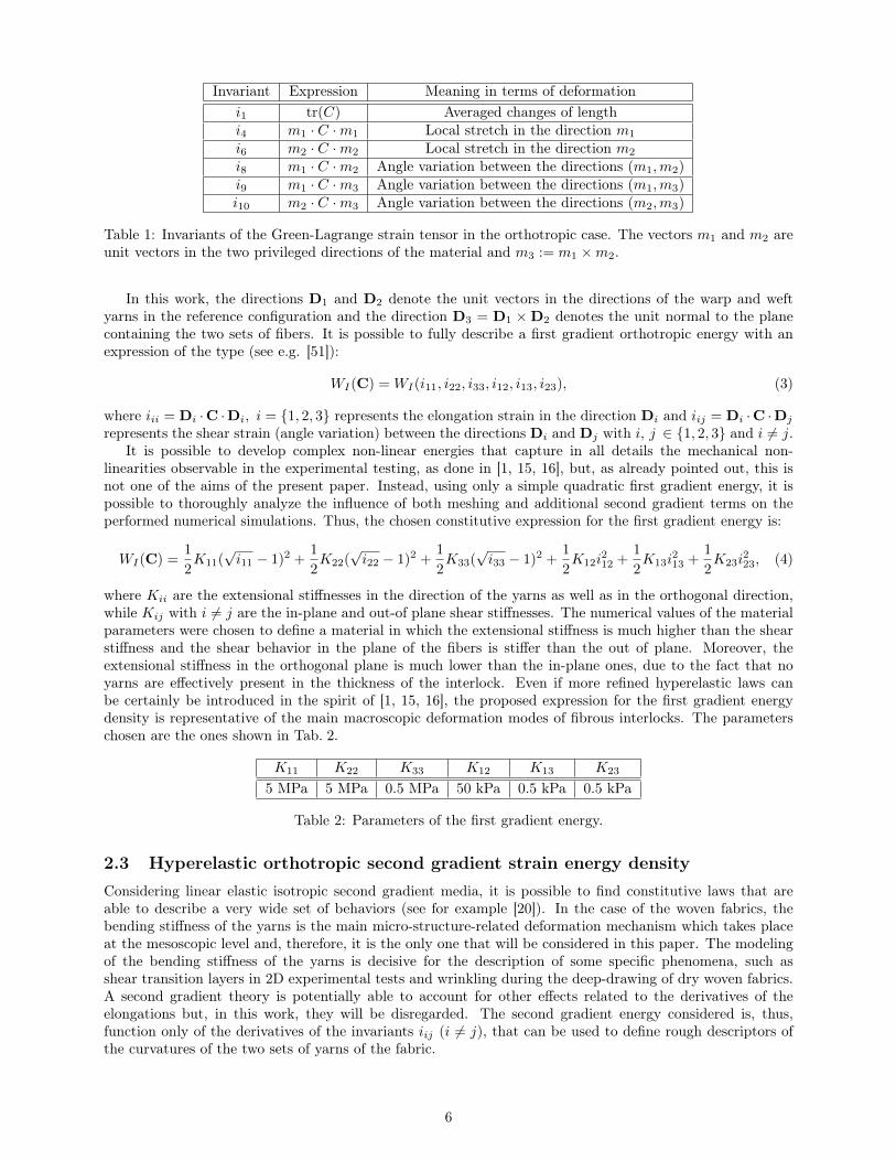
Invariant Expression Meaning in terms of deformationi1 tr(C) Averaged changes of lengthi4 m1 · C ·m1 Local stretch in the direction m1
i6 m2 · C ·m2 Local stretch in the direction m2
i8 m1 · C ·m2 Angle variation between the directions (m1,m2)i9 m1 · C ·m3 Angle variation between the directions (m1,m3)i10 m2 · C ·m3 Angle variation between the directions (m2,m3)
Table 1: Invariants of the Green-Lagrange strain tensor in the orthotropic case. The vectors m1 and m2 areunit vectors in the two privileged directions of the material and m3 := m1 ×m2.
In this work, the directions D1 and D2 denote the unit vectors in the directions of the warp and weftyarns in the reference configuration and the direction D3 = D1 ×D2 denotes the unit normal to the planecontaining the two sets of fibers. It is possible to fully describe a first gradient orthotropic energy with anexpression of the type (see e.g. [51]):
WI(C) = WI(i11, i22, i33, i12, i13, i23), (3)
where iii = Di ·C ·Di, i = 1, 2, 3 represents the elongation strain in the direction Di and iij = Di ·C ·Dj
represents the shear strain (angle variation) between the directions Di and Dj with i, j ∈ 1, 2, 3 and i 6= j.It is possible to develop complex non-linear energies that capture in all details the mechanical non-
linearities observable in the experimental testing, as done in [1, 15, 16], but, as already pointed out, this isnot one of the aims of the present paper. Instead, using only a simple quadratic first gradient energy, it ispossible to thoroughly analyze the influence of both meshing and additional second gradient terms on theperformed numerical simulations. Thus, the chosen constitutive expression for the first gradient energy is:
WI(C) =1
2K11(
√i11 − 1)2 +
1
2K22(
√i22 − 1)2 +
1
2K33(
√i33 − 1)2 +
1
2K12i
212 +
1
2K13i
213 +
1
2K23i
223, (4)
where Kii are the extensional stiffnesses in the direction of the yarns as well as in the orthogonal direction,while Kij with i 6= j are the in-plane and out-of plane shear stiffnesses. The numerical values of the materialparameters were chosen to define a material in which the extensional stiffness is much higher than the shearstiffness and the shear behavior in the plane of the fibers is stiffer than the out of plane. Moreover, theextensional stiffness in the orthogonal plane is much lower than the in-plane ones, due to the fact that noyarns are effectively present in the thickness of the interlock. Even if more refined hyperelastic laws canbe certainly be introduced in the spirit of [1, 15, 16], the proposed expression for the first gradient energydensity is representative of the main macroscopic deformation modes of fibrous interlocks. The parameterschosen are the ones shown in Tab. 2.
K11 K22 K33 K12 K13 K23
5 MPa 5 MPa 0.5 MPa 50 kPa 0.5 kPa 0.5 kPa
Table 2: Parameters of the first gradient energy.
2.3 Hyperelastic orthotropic second gradient strain energy densityConsidering linear elastic isotropic second gradient media, it is possible to find constitutive laws that areable to describe a very wide set of behaviors (see for example [20]). In the case of the woven fabrics, thebending stiffness of the yarns is the main micro-structure-related deformation mechanism which takes placeat the mesoscopic level and, therefore, it is the only one that will be considered in this paper. The modelingof the bending stiffness of the yarns is decisive for the description of some specific phenomena, such asshear transition layers in 2D experimental tests and wrinkling during the deep-drawing of dry woven fabrics.A second gradient theory is potentially able to account for other effects related to the derivatives of theelongations but, in this work, they will be disregarded. The second gradient energy considered is, thus,function only of the derivatives of the invariants iij (i 6= j), that can be used to define rough descriptors ofthe curvatures of the two sets of yarns of the fabric.
6
As a matter of fact, it can be inferred (see also [6, 21, 27, 36, 37]) that, given the family of yarns initiallyoriented in the direction D1, the quantity i12,1 is a measure of their in-plane bending6. Analogously i12,2 is ameasure of the in-plane bending of the family of yarns initially oriented in the direction D2. The quantitiesi13,1 and i23,2 are descriptors of the out-of-plane bending of the yarns initially oriented in the D1 and D2
directions, respectively. Since no material fibers are present in the thickness of the considered interlocks,quantities related to their bending (i13,3 and i23,3) are not likely to play a role in the deformation of suchmaterials. In the light of these remarks, the following constitutive form is introduced for the second gradientstrain energy density:
WII(∇C) =1
2α1 i
212,1 +
1
2α2 i
212,2 +
1
2β1 i
213,1 +
1
2β2 i
223,2, (5)
where with α1, α2 and β1, β2 are the in-plane and out-of-plane bending stiffnesses of the two family ofyarns, respectively. For unbalanced fabrics, i.e. fabrics whose warp and weft yarns do not have the samecharacteristics, it is likely that α1 6= α2 and β1 6= β2 (see also [6, 36]). The object of this paper are interlockswhich are balanced and, hence, it is assumed that α1 = α2 = α and β1 = β2 = β. Moreover, it is possiblethat the two families of yarns have different bending stiffnesses in-plane and out of plane. Nevertheless, suchdifference can be rather small, so in this paper it will also be set α = β. The chosen second gradient energythus takes the particular form:
WII(∇C) =1
2α(i212,1 + i212,2 + i213,1 + i223,2
), (6)
Further investigations are needed to establish a strict theoretical relationship between the microscopicstructure of considered reinforcements and the macroscopic parameters here introduced: it is indeed wellknown that the second gradient parameters are intrinsically related to a characteristic length Lc which is,in turn, associated to the micro-structural properties of considered materials. Many identification methodshave been introduced to relate the macroscopic second gradient parameter to the microscopic properties ofthe considered medium, e.g. see [2, 54]. Suitable multi-scale methods as the one introduced in [43] maybe generalized to be applied to the present case. Moreover, the description of the considered system at themicroscopic scale may exploit some of the results proposed in [4, 32, 55].
3 Numerical model and resultsIn this section, the implemented FEM and the consequent results for the simulation of deep-drawing areshown.
The structure of this section will be as follows:
• in the first subsection, the numerical implementation of the contact interaction between the testingmachine and the interlock is presented,
• in the second subsection the proposed constrained shape functions, that will be here called augmentedcontinuity shape functions and used to perform a numerical simulation of the presented second gradientmodel, will be defined,
• in the third subsection, the influence of the second gradient parameter α on the onset of wrinkles duringthe simulation of the deep-drawing is studied,
• the fourth subsection presents some observed the mesh-dependency result for the first gradient model,when using linear shape functions,
• the final subsection shows the first and second gradient solutions as functions of the adopted mesh, whenusing the augmented continuity shape functions. It is concluded that second gradient simulations arenot significantly affected by the choice of the mesh, provided that the size of the elements is sufficientlysmall.
6Here and in the sequel the term (·),i denotes the partial derivative of the quantity (·) with respect to the space coordinatesξi of a reference frame oriented within the directions Di.
7
3.1 Modeling geometry and contact interaction between the mold and the re-inforcement
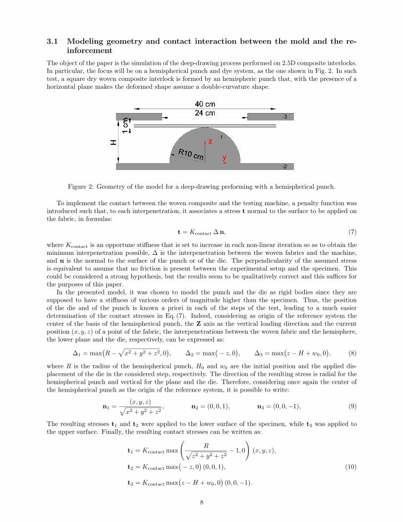
The object of the paper is the simulation of the deep-drawing process performed on 2.5D composite interlocks.In particular, the focus will be on a hemispherical punch and dye system, as the one shown in Fig. 2. In suchtest, a square dry woven composite interlock is formed by an hemispheric punch that, with the presence of ahorizontal plane makes the deformed shape assume a double-curvature shape.
Figure 2: Geometry of the model for a deep-drawing preforming with a hemispherical punch.
To implement the contact between the woven composite and the testing machine, a penalty function wasintroduced such that, to each interpenetration, it associates a stress t normal to the surface to be applied onthe fabric, in formulas:
t = Kcontact ∆n, (7)
where Kcontact is an opportune stiffness that is set to increase in each non-linear iteration so as to obtain theminimum interpenetration possible, ∆ is the interpenetration between the woven fabrics and the machine,and n is the normal to the surface of the punch or of the die. The perpendicularity of the assumed stressis equivalent to assume that no friction is present between the experimental setup and the specimen. Thiscould be considered a strong hypothesis, but the results seem to be qualitatively correct and this suffices forthe purposes of this paper.
In the presented model, it was chosen to model the punch and the die as rigid bodies since they aresupposed to have a stiffness of various orders of magnitude higher than the specimen. Thus, the positionof the die and of the punch is known a priori in each of the steps of the test, leading to a much easierdetermination of the contact stresses in Eq. (7). Indeed, considering as origin of the reference system thecenter of the basis of the hemispherical punch, the Z axis as the vertical loading direction and the currentposition (x, y, z) of a point of the fabric, the interpenetrations between the woven fabric and the hemisphere,the lower plane and the die, respectively, can be expressed as:
∆1 = max(R−
√x2 + y2 + z2, 0
), ∆2 = max
(− z, 0
), ∆3 = max
(z −H + w0, 0
), (8)
where R is the radius of the hemispherical punch, H0 and w0 are the initial position and the applied dis-placement of the die in the considered step, respectively. The direction of the resulting stress is radial for thehemispherical punch and vertical for the plane and the die. Therefore, considering once again the center ofthe hemispherical punch as the origin of the reference system, it is possible to write:
n1 =(x, y, z)√x2 + y2 + z2
, n2 = (0, 0, 1), n3 = (0, 0,−1), (9)
The resulting stresses t1 and t2 were applied to the lower surface of the specimen, while t3 was applied tothe upper surface. Finally, the resulting contact stresses can be written as:
t1 = Kcontact max
(R√
z2 + y2 + z2− 1, 0
)(x, y, z),
t2 = Kcontact max(− z, 0
)(0, 0, 1), (10)
t3 = Kcontact max(z −H + w0, 0
)(0, 0,−1).
8
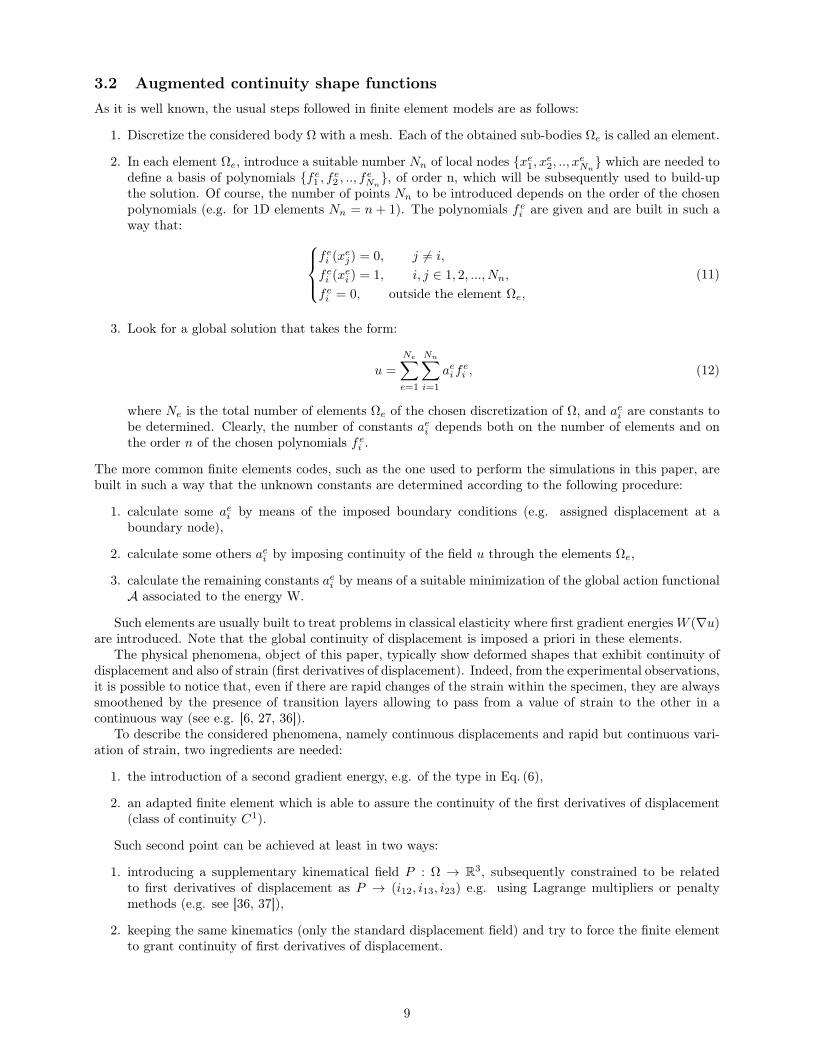
3.2 Augmented continuity shape functionsAs it is well known, the usual steps followed in finite element models are as follows:
1. Discretize the considered body Ω with a mesh. Each of the obtained sub-bodies Ωe is called an element.
2. In each element Ωe, introduce a suitable number Nn of local nodes xe1, xe2, .., xeNn which are needed to
define a basis of polynomials fe1 , fe2 , .., feNn, of order n, which will be subsequently used to build-up
the solution. Of course, the number of points Nn to be introduced depends on the order of the chosenpolynomials (e.g. for 1D elements Nn = n+ 1). The polynomials fei are given and are built in such away that:
fei (xej) = 0, j 6= i,
fei (xei ) = 1, i, j ∈ 1, 2, ..., Nn,
fei = 0, outside the element Ωe,
(11)
3. Look for a global solution that takes the form:
u =
Ne∑e=1
Nn∑i=1
aeifei , (12)
where Ne is the total number of elements Ωe of the chosen discretization of Ω, and aei are constants tobe determined. Clearly, the number of constants aei depends both on the number of elements and onthe order n of the chosen polynomials fei .
The more common finite elements codes, such as the one used to perform the simulations in this paper, arebuilt in such a way that the unknown constants are determined according to the following procedure:
1. calculate some aei by means of the imposed boundary conditions (e.g. assigned displacement at aboundary node),
2. calculate some others aei by imposing continuity of the field u through the elements Ωe,
3. calculate the remaining constants aei by means of a suitable minimization of the global action functionalA associated to the energy W.
Such elements are usually built to treat problems in classical elasticity where first gradient energiesW (∇u)are introduced. Note that the global continuity of displacement is imposed a priori in these elements.
The physical phenomena, object of this paper, typically show deformed shapes that exhibit continuity ofdisplacement and also of strain (first derivatives of displacement). Indeed, from the experimental observations,it is possible to notice that, even if there are rapid changes of the strain within the specimen, they are alwayssmoothened by the presence of transition layers allowing to pass from a value of strain to the other in acontinuous way (see e.g. [6, 27, 36]).
To describe the considered phenomena, namely continuous displacements and rapid but continuous vari-ation of strain, two ingredients are needed:
1. the introduction of a second gradient energy, e.g. of the type in Eq. (6),
2. an adapted finite element which is able to assure the continuity of the first derivatives of displacement(class of continuity C1).
Such second point can be achieved at least in two ways:
1. introducing a supplementary kinematical field P : Ω → R3, subsequently constrained to be relatedto first derivatives of displacement as P → (i12, i13, i23) e.g. using Lagrange multipliers or penaltymethods (e.g. see [36, 37]),
2. keeping the same kinematics (only the standard displacement field) and try to force the finite elementto grant continuity of first derivatives of displacement.
9
In this paper, the authors chose to implement this second way of granting continuity of strain by introduc-ing third order Lagrangian polynomials which guarantee such augmented continuity with a penalty energyat the element interfaces of the type7:
WInterface = KPenalty ([[i12]]2 + [[i13]]2 + [[i23]]2). (13)
This energy depends only on the discontinuity of the deformations i12, i13 and i23 and it is, therefore, notsufficient to render the entire ∇u continuous. Nonetheless, the derivatives of the deformations i12, i13 andi23 are the only ones appearing in the presented second gradient energy and, therefore, are the only ones onwhich the continuity is imposed.
Whit this workaround it was possible to obtain almost continuous deformations and, thus, to implementdirectly a second gradient 3D model. The possibility of adding an energy on the interface between meshelements is not always granted, but it is possible in COMSOLr, the software used for the simulationspresented in the present paper.
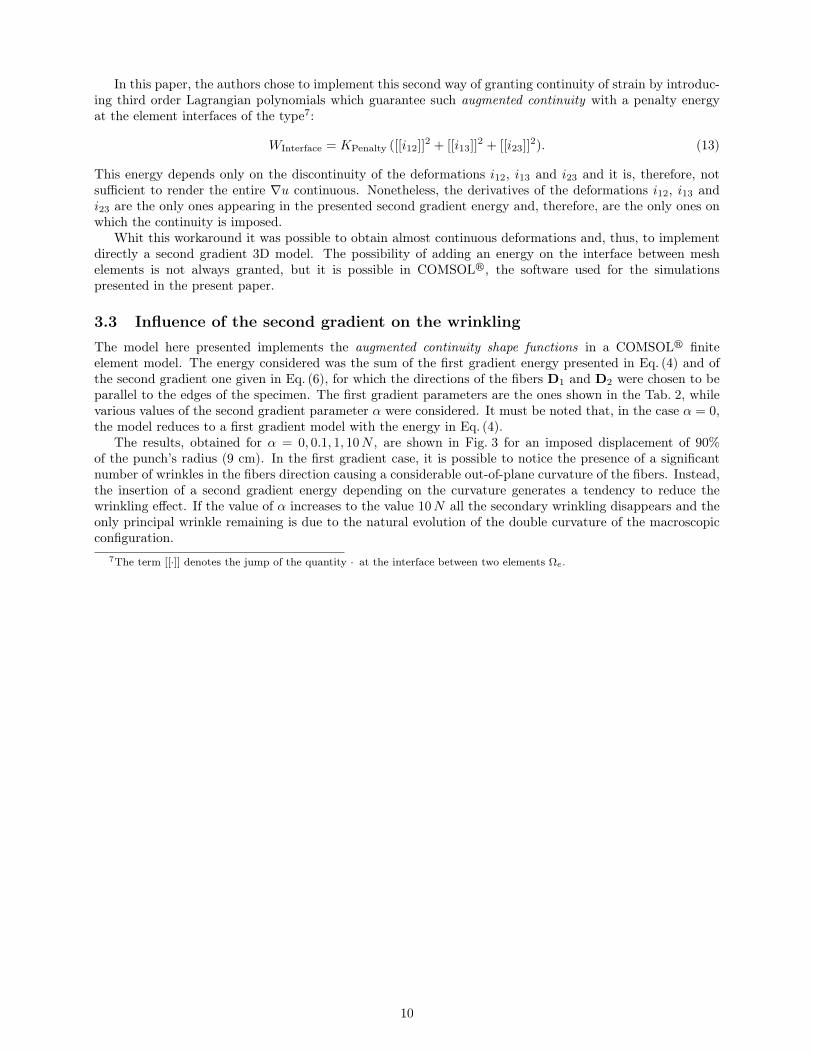
3.3 Influence of the second gradient on the wrinklingThe model here presented implements the augmented continuity shape functions in a COMSOLr finiteelement model. The energy considered was the sum of the first gradient energy presented in Eq. (4) and ofthe second gradient one given in Eq. (6), for which the directions of the fibers D1 and D2 were chosen to beparallel to the edges of the specimen. The first gradient parameters are the ones shown in the Tab. 2, whilevarious values of the second gradient parameter α were considered. It must be noted that, in the case α = 0,the model reduces to a first gradient model with the energy in Eq. (4).
The results, obtained for α = 0, 0.1, 1, 10N , are shown in Fig. 3 for an imposed displacement of 90%of the punch’s radius (9 cm). In the first gradient case, it is possible to notice the presence of a significantnumber of wrinkles in the fibers direction causing a considerable out-of-plane curvature of the fibers. Instead,the insertion of a second gradient energy depending on the curvature generates a tendency to reduce thewrinkling effect. If the value of α increases to the value 10N all the secondary wrinkling disappears and theonly principal wrinkle remaining is due to the natural evolution of the double curvature of the macroscopicconfiguration.
7The term [[·]] denotes the jump of the quantity · at the interface between two elements Ωe.
10
1st gradient model (α = 0 N) α = 0.1 N
α = 1 N α = 10 N
Figure 3: Dependence of the solution on the second gradient parameter α.
As it will be shown in subsections 3.4.1 and 3.4.2, the first gradient model appears to be mesh-dependenteven after the introduction of the augmented continuity shape functions (see Fig. 6) and it is, therefore,impossible to show a representative solution for this case (see subsections 3.4.1 and 3.4.2). Thus, it waschosen to show the deformed shape evaluated with the thinner used mesh, even if it is reasonable to assumethat more wrinkles could appear for thinner meshes. On the other hand, even for small values of the secondgradient parameter α, a stabilization of the deformed configuration is obtained (see Fig. 6) and the deformedshape presented can be considered a representative solution, as it will be shown in subsections 3.4.2.
The possibility of controlling the onset and evolution of wrinkling during the deep-drawing simulation viathe introduction of a constitutive parameter could be of great use in the prevision of the material behavior inview of structure design. It must be reminded that the presented simulations are relative to an experimentaltest that is meant for the characterization of the material constitutive properties. It is, therefore not enoughto correctly describe the experimental results but the final goal is to predict the behavior of the woven fabricin generic engineering applications.
An issue that has to be covered is the determination of the second gradient parameter via experimentaltesting. Considering the proposed simple energy, it could be possible to heuristically choose α in orderto have a qualitative description of the wrinkling phenomenon during a test such as the one proposed here.Furthermore, there are several experimental phenomena whose description would be useful for the calibrationof a second gradient energy. During a Bias Extension Test, it is possible to observe the formation of someshear boundary layers the description of which can be used to calibrate the second energy parameters, asshown in [27]. In the case of a Bias Extension Test on strongly unbalanced fabrics, the bending stiffnessof the fibers can lead to some macroscopic effects like the asymmetric deformed shape analyzed in [6, 36].Finally, the calibration of the second gradient parameter could be attempted via a three point bending ofan interlock, as in [37]. Which combination of these tests is best suited for the determination of the secondgradient parameters is still to be decided, but it is important to have multiple observable effects so that it ispossible to validate the chosen parameters.
The results obtained in this paper are a confirmation of the great potential of the use of a second gradient
11
model for the description of the wrinkling phenomenon and, more generally, of the behavior of compositematerials. In the authors’ opinion, the results presented in this paper and in [6, 27, 36, 37] are starting toclearly show how a second gradient model can be a potential solution for most of the issues relative to thedescription of the behavior of dry woven fibrous composite.
3.4 Some considerations concerning mesh-dependency of the performed simu-lations
3.4.1 First gradient model with linear shape functions
As stated above, the results obtained via a first gradient model appear to be mesh-dependent, due to thenon-stability of the wrinkling description. The aim of this subsection is to present this issue in the case of aclassical first gradient implementation and, hence, to show the stabilization effect obtained with the insertionof a second gradient energy.
The augmented continuity shape functions introduced for the second gradient model are momentarilydiscarded, so that it is possible to frame the mesh-dependency problem in a more traditional setting. In thesimulations of this subsection, it was chosen to implement a model with the Lagrange linear shape functions.The study of the mesh-density’s influence on the first gradient solution is made with two types of mesh,namely:
• hexahedral meshes obtained sweeping quadrilateral meshes on the boundary over the thickness of thespecimen (Fig. 4),
• tetrahedral elements (Fig. 5).
The same results cannot be obtained for the second gradient model because with such low continuity shapefunctions the insertion of a second gradient energy cannot be detected and, hence, it plays no actual role inthe results.
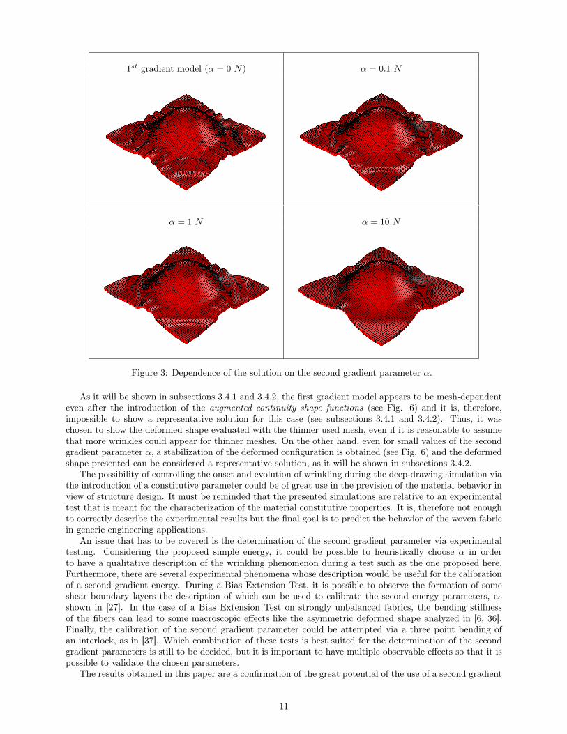
In Fig. 4, the hexahedral meshes and the resulting deformed shapes of the specimen are shown. It isimportant to remark that in this set of meshes the directions of the yarns D1 and D2, that are parallel tothe edges of the specimen, coincide with the normals to the mesh interfaces. This property makes it possibleto have a discontinuity on the derivatives in one of the fiber directions without losing the smoothness in theother direction. In other words, it is possible to form a wrinkle at the element interfaces for one set of fiberskeeping the other set of fiber unaffected. This uncoupling can cause the formation of several wrinkles withoutinterfering in other deformation mechanisms. Being the effect strongly related to the positioning and numberof interfaces between meshes, it is not surprising that the result appears to be mesh-dependent. As a matterof fact, it is possible to see in Fig. 4 how the increase in mesh-density seems to be connected to an incrementin the number of wrinkles.
Mesh
Deformed
shap
e
Figure 4: Solution of a first gradient model with linear shape functions and hexahedral meshes of differentsizes.
12
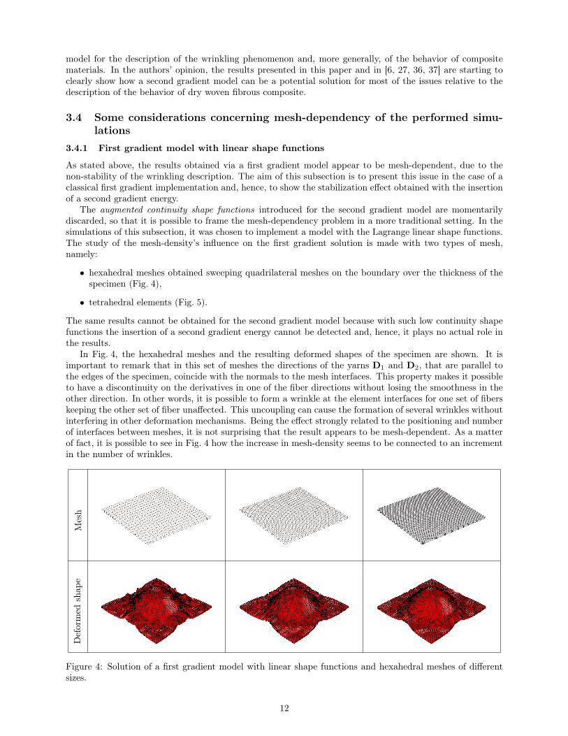
Changing the type of mesh to tetrahedral elements as shown in Fig. 5, the improvement obtained in thestability is very clear. Despite the solution is once again mesh-dependent, the differences obtained in theoutput are much less with respect to the hexahedral mesh. The explanation for this result is that, in thiscase, the normals to the interfaces between the meshes do not always coincide with the direction of the fibersmaking the appearance of a wrinkling phenomenon at the interfaces more difficult.
Mesh
Deformed
shap
e
Figure 5: Solutions for a first gradient model with linear shape functions and tetrahedral elements of differentsizes.
The conclusion on the results presented in this subsection is that a first gradient model with linear shapefunction may present unphysical wrinkling phenomena. It is still possible to obtain realistic results from sucha model, but the dimension and the orientation of the elements should be carefully chosen to avoid unphysicalwrinkling.
3.4.2 First and second gradient models with augmented continuity shape functionss
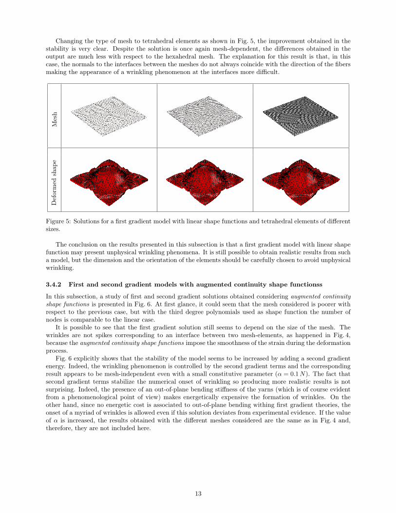
In this subsection, a study of first and second gradient solutions obtained considering augmented continuityshape functions is presented in Fig. 6. At first glance, it could seem that the mesh considered is poorer withrespect to the previous case, but with the third degree polynomials used as shape function the number ofnodes is comparable to the linear case.
It is possible to see that the first gradient solution still seems to depend on the size of the mesh. Thewrinkles are not spikes corresponding to an interface between two mesh-elements, as happened in Fig. 4,because the augmented continuity shape functions impose the smoothness of the strain during the deformationprocess.
Fig. 6 explicitly shows that the stability of the model seems to be increased by adding a second gradientenergy. Indeed, the wrinkling phenomenon is controlled by the second gradient terms and the correspondingresult appears to be mesh-independent even with a small constitutive parameter (α = 0.1N). The fact thatsecond gradient terms stabilize the numerical onset of wrinkling so producing more realistic results is notsurprising. Indeed, the presence of an out-of-plane bending stiffness of the yarns (which is of course evidentfrom a phenomenological point of view) makes energetically expensive the formation of wrinkles. On theother hand, since no energetic cost is associated to out-of-plane bending withing first gradient theories, theonset of a myriad of wrinkles is allowed even if this solution deviates from experimental evidence. If the valueof α is increased, the results obtained with the different meshes considered are the same as in Fig. 4 and,therefore, they are not included here.
13
Mesh
1stgrad
ient
α=
0.1N
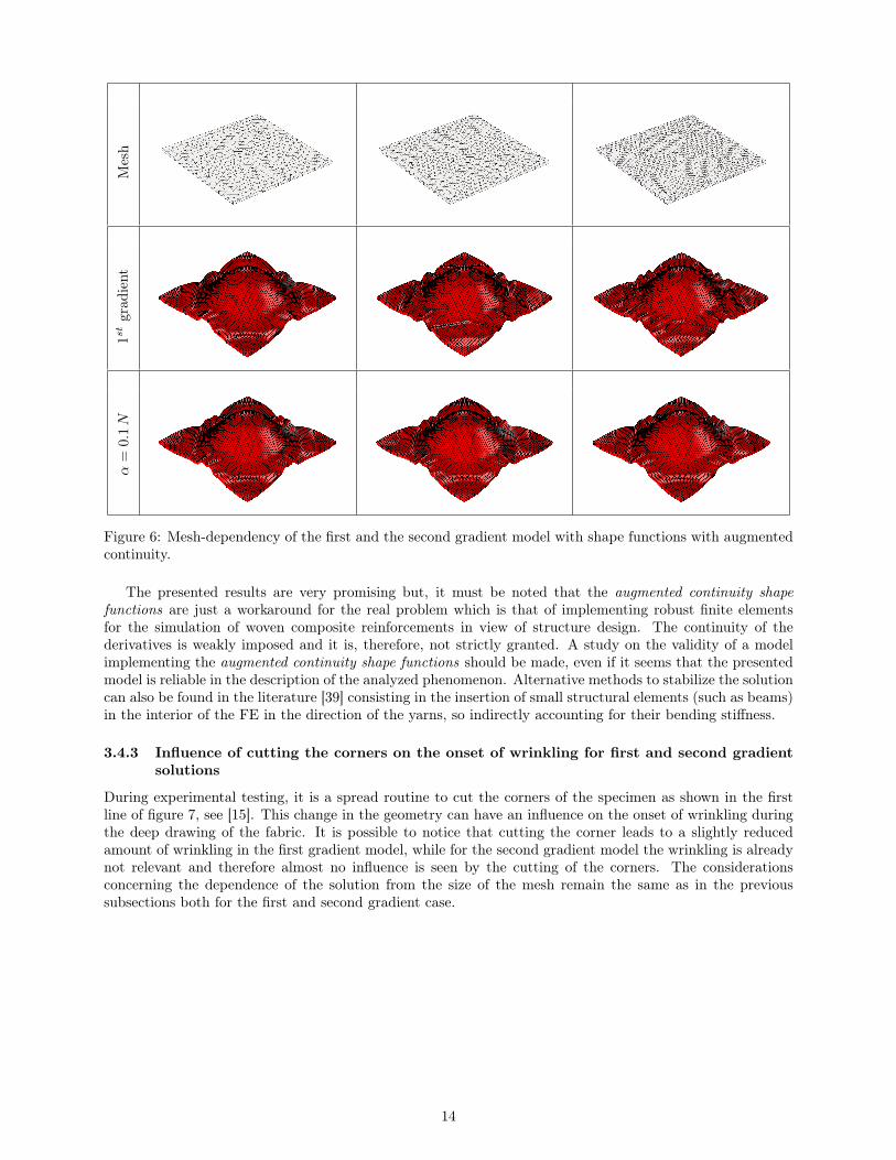
Figure 6: Mesh-dependency of the first and the second gradient model with shape functions with augmentedcontinuity.
The presented results are very promising but, it must be noted that the augmented continuity shapefunctions are just a workaround for the real problem which is that of implementing robust finite elementsfor the simulation of woven composite reinforcements in view of structure design. The continuity of thederivatives is weakly imposed and it is, therefore, not strictly granted. A study on the validity of a modelimplementing the augmented continuity shape functions should be made, even if it seems that the presentedmodel is reliable in the description of the analyzed phenomenon. Alternative methods to stabilize the solutioncan also be found in the literature [39] consisting in the insertion of small structural elements (such as beams)in the interior of the FE in the direction of the yarns, so indirectly accounting for their bending stiffness.
3.4.3 Influence of cutting the corners on the onset of wrinkling for first and second gradientsolutions
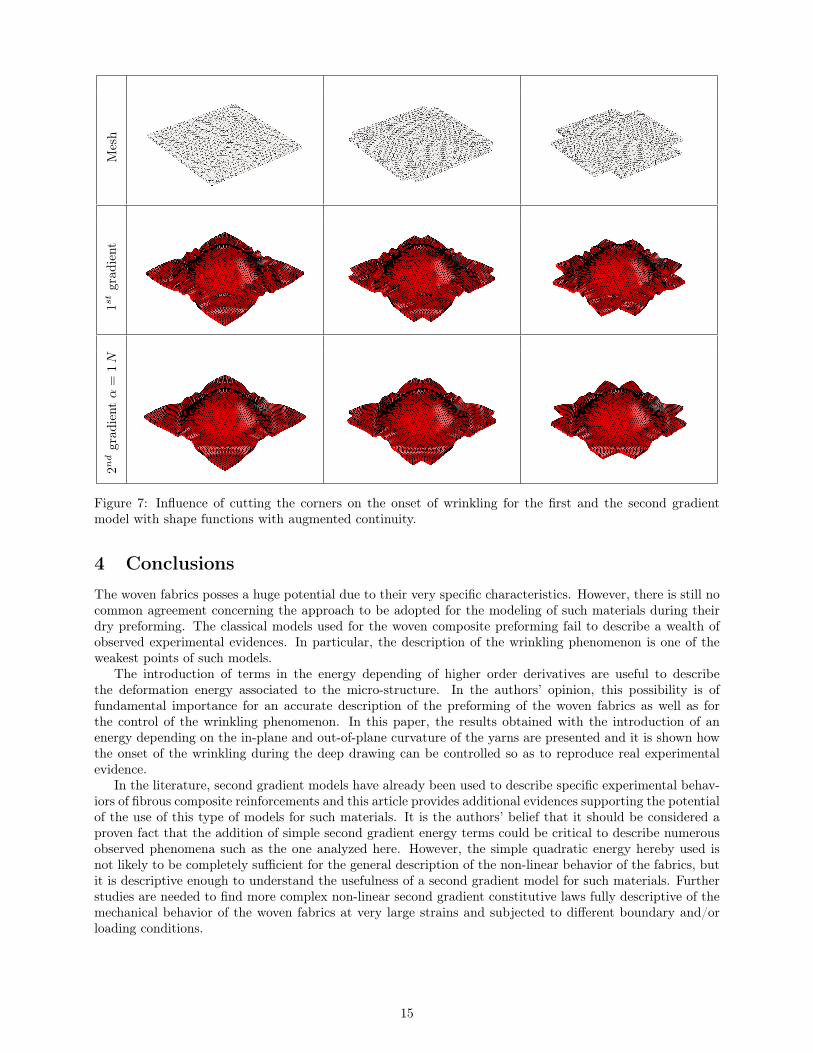
During experimental testing, it is a spread routine to cut the corners of the specimen as shown in the firstline of figure 7, see [15]. This change in the geometry can have an influence on the onset of wrinkling duringthe deep drawing of the fabric. It is possible to notice that cutting the corner leads to a slightly reducedamount of wrinkling in the first gradient model, while for the second gradient model the wrinkling is alreadynot relevant and therefore almost no influence is seen by the cutting of the corners. The considerationsconcerning the dependence of the solution from the size of the mesh remain the same as in the previoussubsections both for the first and second gradient case.
14
Mesh
1stgrad
ient
2ndgrad
ientα
=1N
Figure 7: Influence of cutting the corners on the onset of wrinkling for the first and the second gradientmodel with shape functions with augmented continuity.
4 ConclusionsThe woven fabrics posses a huge potential due to their very specific characteristics. However, there is still nocommon agreement concerning the approach to be adopted for the modeling of such materials during theirdry preforming. The classical models used for the woven composite preforming fail to describe a wealth ofobserved experimental evidences. In particular, the description of the wrinkling phenomenon is one of theweakest points of such models.
The introduction of terms in the energy depending of higher order derivatives are useful to describethe deformation energy associated to the micro-structure. In the authors’ opinion, this possibility is offundamental importance for an accurate description of the preforming of the woven fabrics as well as forthe control of the wrinkling phenomenon. In this paper, the results obtained with the introduction of anenergy depending on the in-plane and out-of-plane curvature of the yarns are presented and it is shown howthe onset of the wrinkling during the deep drawing can be controlled so as to reproduce real experimentalevidence.
In the literature, second gradient models have already been used to describe specific experimental behav-iors of fibrous composite reinforcements and this article provides additional evidences supporting the potentialof the use of this type of models for such materials. It is the authors’ belief that it should be considered aproven fact that the addition of simple second gradient energy terms could be critical to describe numerousobserved phenomena such as the one analyzed here. However, the simple quadratic energy hereby used isnot likely to be completely sufficient for the general description of the non-linear behavior of the fabrics, butit is descriptive enough to understand the usefulness of a second gradient model for such materials. Furtherstudies are needed to find more complex non-linear second gradient constitutive laws fully descriptive of themechanical behavior of the woven fabrics at very large strains and subjected to different boundary and/orloading conditions.
15
5 References[1] Yamina Aimène, Emmanuelle Vidal-Sallé, Benjamin Hagège, François Sidoroff, and Philippe Boisse. A hyperelastic approach
for composite reinforcement large deformation analysis. Journal of Composite Materials, 44(1):5–26, 2010.
[2] Jean-Jacques Alibert, Pierre Seppecher, and Francesco dell’Isola. Truss modular beams with deformation energy dependingon higher displacement gradients. Mathematics and Mechanics of Solids, 8(1):51–73, 2003.
[3] Holm Altenbach, Victor A. Eremeyev, Leonid P. Lebedev, and Leonardo A. Rendón. Acceleration waves and ellipticity inthermoelastic micropolar media. Archive of Applied Mechanics, 80(3):217–227, 2010.
[4] Ali Asghar Atai and David J. Steigmann. On the nonlinear mechanics of discrete networks. Archive of Applied mechanics,67(5):303–319, 1997.
[5] Daniel Balzani, Patrizio Neff, Jörg Schröder, and Gerhard A. Holzapfel. A polyconvex framework for soft biological tissues.Adjustment to experimental data. International Journal of Solids and Structures, 43(20):6052–6070, 2006.
[6] Gabriele Barbagallo, Angela Madeo, Ismael Azehaf, Ivan Giorgio, Fabrice Morestin, and Philippe Boisse. Bias extension teston an unbalanced woven composite reinforcement: Experiments and modeling via a second-gradient continuum approach.Journal of Composite Materials, 2016.
[7] Jeffrey L. Bleustein. A note on the boundary conditions of Toupin’s strain-gradient theory. International Journal of Solidsand Structures, 3(6):1053–1057, 1967.
[8] Philippe Boisse, K. Buet, Alain Gasser, and Jean Launay. Meso/macro-mechanical behaviour of textile reinforcements forthin composites. Composites Science and Technology, 61(3):395–401, 2001.
[9] Philippe Boisse, A. Hakim Cherouat, Jean Claude Gelin, and Hamid Sabhi. Experimental study and finite element simu-lation of a glass fiber fabric shaping process. Polymer composites, 16(1):83–95, 1995.
[10] Philippe Boisse, Nahiène Hamila, F. Helenon, B. Hagege, and Jian Cao. Different approaches for woven composite rein-forcement forming simulation. International Journal of Material Forming, 1(1):21–29, 2008.
[11] Philippe Boisse, Nahiène Hamila, Emmanuelle Vidal-Sallé, and François Dumont. Simulation of wrinkling during textilecomposite reinforcement forming. Influence of tensile, in-plane shear and bending stiffnesses. Composites Science andTechnology, 71(5):683–692, 2011.
[12] Philippe Boisse, Bassem Zouari, and Jean-Luc Daniel. Importance of in-plane shear rigidity in finite element analyses ofwoven fabric composite preforming. Composites Part A: Applied Science and Manufacturing, 37(12):2201–2212, 2006.
[13] Philippe Boisse, Bassem Zouari, and Alain Gasser. A mesoscopic approach for the simulation of woven fibre compositeforming. Composites Science and Technology, 65(3-4):429–436, 2005.
[14] Jian Cao, Remko Akkerman, Philippe Boisse, Julie Chen, H. S. Cheng, E. F. de Graaf, J. L. Gorczyca, Philip Harrison,Gilles Hivet, Jérôme Launay, Wonoh Lee, L. Liu, Stepan V. Lomov, Andrew C. Long, Emmanuel de Luycker, FabriceMorestin, J. Padvoiskis, X. Q. Peng, James Sherwood, T. Stoilova, Xiaoming M. Tao, I. Verpoest, A. Willems, J. Wiggers,T. X. Yu, and B. Zhu. Characterization of mechanical behavior of woven fabrics: Experimental methods and benchmarkresults. Composites Part A: Applied Science and Manufacturing, 39(6):1037–1053, 2008.
[15] Adrien Charmetant, Jean Guillaume Orliac, Emmanuelle Vidal-Sallé, and Philippe Boisse. Hyperelastic model for largedeformation analyses of 3D interlock composite preforms. Composites Science and Technology, 72(12):1352–1360, 2012.
[16] Adrien Charmetant, Emmanuelle Vidal-Sallé, and Philippe Boisse. Hyperelastic modelling for mesoscopic analyses ofcomposite reinforcements. Composites Science and Technology, 71(14):1623–1631, 2011.
[17] Eugène Cosserat and François Cosserat. Théorie des corps déformables (engl. translation by D. Delphenich 2007, pdfavailable at http://www.uni-due.de/%7ehm0014/Cosserat_files/Cosserat09_eng.pdf). 1909.
[18] Emmanuel de Luycker, Fabrice Morestin, Philippe Boisse, and David Marsal. Simulation of 3D interlock composite pre-forming. Composite Structures, 88:615–623, 2009.
[19] Emmanuel de Luycker, Jean Guillaume Orliac, Fabrice Morestin, Philippe Boisse, David Marsal, and Stephane Otin.Experimental and numerical analyses of 3D interlock composite preforming. International Journal of Material Forming,3(1):719–722, 2010.
[20] Francesco dell’Isola, Giulio Sciarra, and Stefano Vidoli. Generalized Hooke’s law for isotropic second gradient materials.Proceedings of the Royal Society A: Mathematical, Physical and Engineering Sciences, 465(2107):2177–2196, 2009.
[21] Francesco dell’Isola and David J. Steigmann. A two-dimensional gradient-elasticity theory for woven fabrics. Journal ofElasticity, 118(1):113–125, 2015.
[22] J. P. Dumont, Pierre Ladeveze, M. Poss, and Yves Remond. Damage mechanics for 3-D composites. Composite Structures,8(2):119–141, 1987.
[23] Damien Durville. Numerical simulation of entangled materials mechanical properties. Journal of Materials Science,40(22):5941–5948, 2005.
[24] Victor A. Eremeyev. Acceleration waves in micropolar elastic media. Doklady Physics, 50(4):204–206, 2005.
[25] Victor A. Eremeyev, Leonid P. Lebedev, and Holm Altenbach. Foundations of micropolar mechanics. Springer BerlinHeidelberg, 2013.
[26] Ahmed Cemal Eringen. Microcontinuum field theories. Springer-Verlag, New York, 1999.
[27] Manuel Ferretti, Angela Madeo, Francesco dell’Isola, and Philippe Boisse. Modeling the onset of shear boundary layers infibrous composite reinforcements by second-gradient theory. Zeitschrift für Angewandte Mathematik und Physik, 65(3):587–612, 2014.
16
[28] Sébastien Gatouillat, Andrea Bareggi, Emmanuelle Vidal-Sallé, and Philippe Boisse. Meso modelling for composite pre-form shaping - Simulation of the loss of cohesion of the woven fibre network. Composites Part A: Applied Science andManufacturing, 54:135–144, 2013.
[29] Paul Germain. The method of virtual power in continuum mechanics. Part 2: Microstructure. SIAM Journal on AppliedMathematics, 25(3):556–575, 1973.
[30] Albert Edward Green and Ronald S. Rivlin. Multipolar continuum mechanics. Archive for Rational Mechanics andAnalysis, 17(2):113–147, 1964.
[31] Nahiène Hamila and Philippe Boisse. A meso-macro three node finite element for draping of textile composite preforms.Applied Composite Materials, 14(4):235–250, 2007.
[32] Eliza M. Haseganu and David J. Steigmann. Equilibrium analysis of finitely deformed elastic networks. ComputationalMechanics, 17(6):359–373, 1996.
[33] Gerhard A. Holzapfel, Thomas C. Gasser, and Ray W. Ogden. A new constitutive framework for arterial wall mechanicsand a comparative study of material models. Journal of Elasticity, 61(1-3):1–48, 2000.
[34] Mikhail Itskov and Nuri Aksel. A class of orthotropic and transversely isotropic hyperelastic constitutive models based ona polyconvex strain energy function. International Journal of Solids and Structures, 41(14):3833–3848, 2004.
[35] Wonoh Lee, J. Padvoiskis, Jian Cao, Emmanuel de Luycker, Philippe Boisse, Fabrice Morestin, J. Chen, and JamesSherwood. Bias-extension of woven composite fabrics. International Journal of Material Forming, 1(SUPPL. 1):895–898,2008.
[36] Angela Madeo, Gabriele Barbagallo, Marco Valerio d’Agostino, and Philippe Boisse. Continuum and discrete models forunbalanced woven fabrics. International Journal of Solids and Structures, 2016.
[37] Angela Madeo, Manuel Ferretti, Francesco dell’Isola, and Philippe Boisse. Thick fibrous composite reinforcements behaveas special second-gradient materials: three-point bending of 3D interlocks. Zeitschrift für Angewandte Mathematik undMechanik, 66(4):2041–2060, 2015.
[38] Sylvain Mathieu, Philippe Boisse, Nahiène Hamila, and Florent Bouillon. Locking and stability of 3D woven compositereinforcements. Key Engineering Materials, 611-612:292–299, 2014.
[39] Sylvain Mathieu, Nahiène Hamila, F. Dupé, C. Descamps, and Philippe Boisse. Stability of 3D Textile Composite Rein-forcement Simulations: Solutions to Spurious Transverse Modes. Applied Composite Materials, 2016.
[40] Amin Mikdam, Ahmed Makradi, Said Ahzi, Hamid Garmestani, Dongsheng S. Li, and Yves Remond. Effective conductivityin isotropic heterogeneous media using a strong-contrast statistical continuum theory. Journal of the Mechanics and Physicsof Solids, 57(1):76–86, 2009.
[41] Amin Mikdam, Ahmed Makradi, Said Ahzi, Hamid Garmestani, Dongsheng S. Li, and Yves Remond. Statistical continuumtheory for the effective conductivity of fiber filled polymer composites: Effect of orientation distribution and aspect ratio.Composites Science and Technology, 70(3):510–517, 2010.
[42] Raymond David Mindlin. Micro-structure in linear elasticity. Archive for Rational Mechanics and Analysis, 16(1):51–78,1964.
[43] Ben Nadler, Panayiotis Papadopoulos, and David J. Steigmann. Multiscale constitutive modeling and numerical simulationof fabric material. International Journal of Solids and Structures, 43(2):206–221, 2006.
[44] Ray W. Ogden. Non-linear elastic deformations, volume 1. 1984.
[45] Victor G. Oshmyan, Stanislav A. Patlazhan, and Yves Remond. Principles of structural-mechanical modeling of polymersand composites. Polymer Science Series A, 48(9):1004–1013, 2006.
[46] Richard S. Parnas. Liquid Composite Molding. 2000.
[47] Juan Pazmino, Sylvain Mathieu, Valter Carvelli, Philippe Boisse, and Stepan V. Lomov. Numerical modelling of forming of anon-crimp 3D orthogonal weave E-glass composite reinforcement. Composites Part A: Applied Science and Manufacturing,72:207–218, 2015.
[48] Wojciech Pietraszkiewicz and Victor A. Eremeyev. On vectorially parameterized natural strain measures of the non-linearCosserat continuum. International Journal of Solids and Structures, 46(11-12):2477–2480, 2009.
[49] Gabbro Piola. Memoria intorno alle equazioni fondamentali del movimento di corpi qualsivogliono considerati secondo lanaturale loro forma e costituzione. Modena, Tipi del R.D. Camera, 1846.
[50] Kevin D. Potter. The early history of the resin transfer moulding process for aerospace applications. 1999.
[51] Annie Raoult. Symmetry groups in nonlinear elasticity: an exercise in vintage mathematics. Communications on Pure andApplied Analysis, 8(1):435–456, 2008.
[52] Chris D. Rudd, Andrew C. Long, K. N. Kendall, and C. Mangin. Liquid moulding technologies: Resin transfer moulding,structural reaction injection moulding and related processing techniques. 1997.
[53] Jörg Schröder, Patrizio Neff, and Daniel Balzani. A variational approach for materially stable anisotropic hyperelasticity.International Journal of Solids and Structures, 42(15):4352–4371, 2005.
[54] Pierre Seppecher, Jean-Jacques Alibert, and Francesco dell’Isola. Linear elastic trusses leading to continua with exoticmechanical interactions. Journal of Physics: Conference Series, 319(1):012018, 2011.
[55] David J. Steigmann. Equilibrium of prestressed networks. IMA Journal of Applied Mathematics, 48(2):195–215, 1992.
[56] David J. Steigmann. Invariants of the stretch tensors and their application to finite elasticity theory. Mathematics andMechanics of Solids, 7(4):393–404, 2002.
17

[57] David J. Steigmann. Frame-invariant polyconvex strain-energy functions for some anisotropic solids. Mathematics andMechanics of Solids, 8(5):497–506, 2003.
[58] Richard A. Toupin. Theories of elasticity with couple-stress. Archive for Rational Mechanics and Analysis, 17(2):85–112,1964.
[59] Peng Wang, Xavier Legrand, Philippe Boisse, Nahiène Hamila, and Damien Soulat. Experimental and numerical analysesof manufacturing process of a composite square box part: Comparison between textile reinforcement forming and surface3D weaving. Composites Part B: Engineering, 78:26–34, 2015.
[60] Bassem Zouari, Jean-Luc Daniel, and Philippe Boisse. A woven reinforcement forming simulation method. Influence of theshear stiffness. Computers & Structures, 84(5-6):351–363, 2006.
18