Can Earthquake Loss Models be Validated Using Field Observations
Upload
balabtechitCategory
view
1download
0
Scientia Iranica B (2012) 19 (3), 472–482
Sharif University of Technology
Scientia IranicaTransactions B: Mechanical Engineering
www.sciencedirect.com
Evaluation of flapping wing propulsion based on a newexperimentally validated aeroelastic modelS.H. Pourtakdoust a, S. Karimain Aliabadi b,∗a Center of Excellence in Aerospace Systems, Sharif University of Technology, Tehran, P.O. Box 11365-11155, IranbDepartment of Aerospace Engineering, Sharif university of Technology, Tehran, P.O. Box: 11365-11155, Iran
Received 1 October 2011; revised 13 February 2012; accepted 14 March 2012
KEYWORDSFlapping air vehicle;Aeroelastic model;Propulsion;Experimental study;Parametric study;Dimensionless parameter.
Abstract To evaluate the propulsion system capabilities of a Flapping Micro Air Vehicle (FMAV), a newaeroelastic model of a typical flexible FMAV is developed, utilizing the Euler–Bernoulli torsion beamand quasi steady aerodynamic model. The new model accounts for all existing complex interactionsbetween the mass, inertia, elastic properties, aerodynamic loading, flapping amplitude and frequency ofthe FMAV, as well as the effects of several geometric and design parameters. To validate the proposedtheoretical model, a typical FMAV, as well as an instrumented test stand for the online measurementof forces, flapping angle and power consumption, has been constructed. The experimental results areinitially utilized to validate the flight dynamic model, and several appropriate conclusions are drawn.The model is subsequently used to demonstrate the flapping propulsion characteristics of the FMAV viasimulation. Using dimensionless parameters, a set of new aeroelastic coordinates are introduced. In thisreduced design space, new generalized performance curves have been deduced. The results indicate thatby proper adjustment of the wing stiffness parameter, as a function of reduced frequency, the FMAV willattain its optimum propulsive efficiency. This fact raises additional ideas of utilizing intelligent variablestiffness materials and/or an active morphing technology for the sustained flight of FMAVs.
© 2012 Sharif University of Technology. Production and hosting by Elsevier B.V. All rights reserved.
1. Introduction
The study of flexible Flapping-wing Micro Air Vehicles(FMAVs) has fascinated many researchers because of theiraerodynamic benefits, especially in their low Reynolds numberand small size [1]. Because of their special advantages ofsmall size, low velocity, high agility and maneuverability,micro or small ornithopters are being potentially consideredfor applications in rescue missions, remote sensing and spyand reconnaissance operations in small/closed media. Suchcapabilities will also be useful in confined environments,where direct or remote human assistance is not feasible [2].Civilian use of autonomous FMAVs will in time exceed military
∗ Corresponding author. Tel.: +98 21 66164628; fax: +98 21 66089640.E-mail address: [email protected] (S.K. Aliabadi).
Peer review under responsibility of Sharif University of Technology.
1026-3098© 2012 Sharif University of Technology. Production and hosting by Els
doi:10.1016/j.scient.2012.03.004
applications. The ability to explore toxic or dangerous spaceswithout human involvement will be of great interest for manyindustries [3]. Applications in such environments include thefollowing: air-quality sampling in nonattainment areas, utilityinspection (power lines, oil pipes), traffic control, monitoring,installation of small pieces, and examination of inaccessibleconfined spaces (buildings, towers).
In addition to all of the profound advantages of FMAVs,the lack of an adequate flight dynamics model for this groupof MAVs is still challenging [4]. Flapping flyers, inspiredfrom biological flappers, have a flexible wing structure. Theyuse the root cyclic driving input (cranking moment) and apassive bending and twisting motion due to flexibility inboth span-wise and chord-wise directions. The flapping offlexible wings is characterized by the simultaneous generationof lift and thrust forces. Consequently, the fluid and structuraldynamics of these flyers are closely linked to each other [5].Moreover, the characteristics of loads acting on the vehicle,including aerodynamic, inertia and internal elastic loads,vary substantially over one flapping cycle [6]. Therefore,understanding the aerodynamic, structural and flight dynamic
evier B.V. All rights reserved.
S.H. Pourtakdoust, S.K. Aliabadi / Scientia Iranica, Transactions B: Mechanical Engineering 19 (2012) 472–482 473
Nomenclature
Symbol Parameter descriptionAC Aerodynamic centerAOA Angle of attackAR Wing aspect ratiob Wing spanC Chord lengthC Wing mean chordCG Center of gravityCL Section lift coefficientCD Section drag coefficientCLMax Max section lift coefficientCDMax Max section drag coefficientCF Axial (thrust) force coefficientd LE spar thicknessEA Elastic axisf Flapping frequencyfR Reduced frequencyFX Forward force generatedFX Average thrust generatedFZ Normal force generatedF Z Average lift generatedg Gravity accelerationGJ Wing torsional stiffnessIY Section moment of inertia over EAkW Wing dimensionless torsional stiffnessL Body lengthL1 Runner crank lengthL2 Wing hinge point locationL3 Mechanism fixed distanceL4 Driving main gear radiusm Wing massMT Total massM Wing driving momentn Number of ribsP Consumed powerP Average power consumptionS Wing areaT Flapping periodU Forward velocityUref Reference velocityV Resultant velocityW Downward velocityx Distance between LE and CGXCG CG location from LEXEA EA location from LEy Distance from wing rootα Effective angle of attackγ Wing flapping angleηP Propulsive efficiencyγUp Highest upstroke angleγDn Highest downstroke angleΓ Overall flapping courseϕ Wing twist angleρ Wing densityρAir Air density.
attributes of flapping is necessary to design high-performanceand robust FMAVs [7].
In recent years, many researchers have focused on exploringthe complex nature of flapping flight. These efforts can be clas-
sified into three main groups: derivation of analytical models,computational or numerical simulations and experimental in-vestigations. In most flapping models, a known bending and/ortorsional profile has been assumed [8,9]. This profilemay reflectthe experimental trends obtained via measurement of the wingdeflection. In [10], different upstroke and downstroke flappingtrajectories are introduced, based on quasi-steady aerodynam-ics. More extensive studies by this group have adopted bothwing rotation magnitude and phase delay as independent pa-rameters [11]. Using predefined deformations will obviouslysimplify the aeroelastic modeling of FMAV, but, doing so, willadversely reduce the model’s integrity.
Some other efforts in the analytical domain can be addressedby multi-body dynamics models, which are formulated basedon Lagrange generalized coordinates and shape integral func-tions [12,13]. A wing-body flight dynamics model of FMAV hasbeen applied for kinematic optimization in [14]. The applica-tion of a typical FMAV multi-body model for state estimationand control synthesis has been proposed in [15]. In all thesestudies, the wing is modeled as a rigid lumped body; therefore,the aeroelastic nature of the flappingwing is not adequately ad-dressed.
Many other studies have tried to implement the flappingproblem in a numerical and computational framework [16,17].They have utilized a panel method combined with FEM toestimate flapping forces. The effects of the angle-of-attackprofile on the propulsive efficiency of an oscillating foil havebeen examined numerically in [18], using VLM and FEM on thesamegeometry. Although the numerical simulations that utilizeFEM and/or CFDmodelsmay lead to accurate solutions, the lackof physical interpretation and the higher costs associated withthese methods limit their applications.
Along with these analytical attempts, many experimentalefforts have also been undertaken in FMAV research. Dueto the complex and partially unknown nature of flappingaerodynamics, experimental studies play a significant role, bothin determining the empirical relations between parameters andvalidating the associated mathematical models. In [19], it hasbeen experimentally shown that wing bending, in addition totwisting, results in slightlymore thrust but lower lift. Accordingto this and experimental results of [20,21], the torsionaldeformation of thewing is shown to be the only dominant effectin aeroelastic analysis. It has been experimentally revealed thatadjusting the torsional stiffness of the wing will result in a 40%efficiency gain [22]. In the most recently published research,FMAV cruise performance has been investigated based on aseries of wind tunnel tests [23].
There are some experimental investigations on developingnew aerodynamic models [24,25]. Some researchers haveconsidered the transient aerodynamic analysis of FMAVs usingthe frequency domain introduced by Theodorson and Peter’sfinite states method [1]. Despite their additional complexities,most researchers have found these methods to be lessprofitable. Particularly in the range of low reduced frequencies,the simple quasi-steady method has been proven to getdesirable accuracy [26].
A key item implicitly addressed in most existing relatedresearch is the complex effect of wing flexibility and stiffnesscharacteristics on the resulting aerodynamics and propulsionefficiency of FMAVs. Additionally, as many important studiesindicate, there are still many unanswered questions that havenot been adequately addressed by the existing literature,some of which include the integrated role of geometric,structural properties and wing kinematics on the aero-propulsive characteristics of the flappingwing, the role of active
474 S.H. Pourtakdoust, S.K. Aliabadi / Scientia Iranica, Transactions B: Mechanical Engineering 19 (2012) 472–482
morphing technology on the flight performance optimizationof FMAVs and the impact of experimental investigations on thedevelopment of high-fidelity simulations and/or reduced-ordermodeling of FMAVs.
It is within this context that the current study has focusedon the derivation of a new set of design and/or performancecurves based on comprehensive coupled aeroelastic models.This FMAV flight dynamics model has been validated by the ex-perimentally observed behavior of a typical FMAV. The math-ematical model developed in the current study accounts forall inherent aeroelastic features of a flapping wing. The elas-tic torsional wing equation of motion (utilizing Euler–Bernoullielastic beam) is supposed to be augmented with pertinentaerodynamics and induced mass-inertia loadings as a forcingfunction. Due to the relatively small reduced frequencies ap-plied by the flapping mechanism, the quasi-steady approach tothe computation of aerodynamic loadings is applicable in thepresent work [27].
The model output is subsequently used to compute theinstantaneous reaction forces and moments related to theFMAV thrust and propulsive efficiency. The validated FMAVflight simulation is then utilized to create new generalizedperformance curves in terms of dimensionless parameters. Thehighly complicated flapping flight dynamics are shown to beadequately addressed via two sets of new coordinates. Theyinclude reduced frequency (as frequently referred) and a newgrouped parameter composed of wing mass, acceleration andstiffness. Remarkable conclusions are drawn based on theseobtained plots. The model developed, and innovative extractedcurves, could be useful in many areas of design, trajectorysimulation, performance analysis and optimization of FMAVs.
This paper is organized as follows. Flapping wing aero-dynamics are described in Section 2. Wing kinematics andaeroelastic modeling are presented in Section 3. Derivation ofthe reaction forces and mechanical power consumption aredescribed in Section 4. Explanation of the constructed exper-imental setup is mentioned in Section 5. Implementation andsimulation results are declared in Section 6. The validation anal-ysis is presented in Section 7. Derivation of generalized curvesand a relevant discussion are presented in Section 8. Finally,concluding remarks and areas warranting further study are dis-cussed in Section 9.
2. Aerodynamic model
The wing forward and flapping motion in the air causesvariable aerodynamic forces to be generated. As frequentlyindicated in the literature, flapping flight aerodynamics havenot yet been fully discovered. In this section, the quasisteady model of flapping wing aerodynamics is presented. Thevalidity of quasi-steady aerodynamics is strongly affected by adimensionless parameter, called reduced frequency, which isdefined as follows [6]:
fR = bf /Uref . (1)
The quantity, Uref , is a reference velocity, which can be FMAVforward, or the wing tip mean stroke velocity [19]. For highvalues of fR, the quasi-steady assumption fails, and transientanalysis must be used. In the typical case of a low-flapping-frequency FMAV, fR is relatively low, approximately in the rangeof 1–10. Utilizing a 2-D strip theory,whose parameters (velocityvector and AOA) are updated according to both deformationfield and input flapping kinematics, is shown to be wellapplicable to low reduced frequencies [27,28].
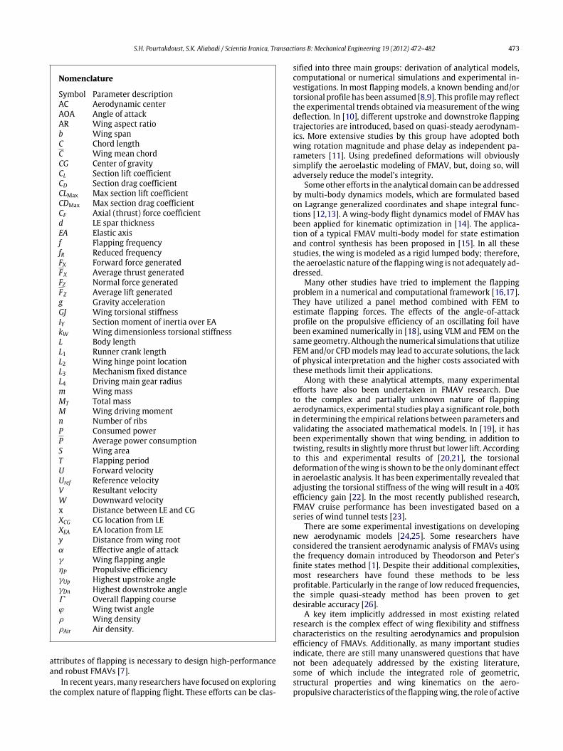
Figure 1: Wing sections introduced by strip theory.
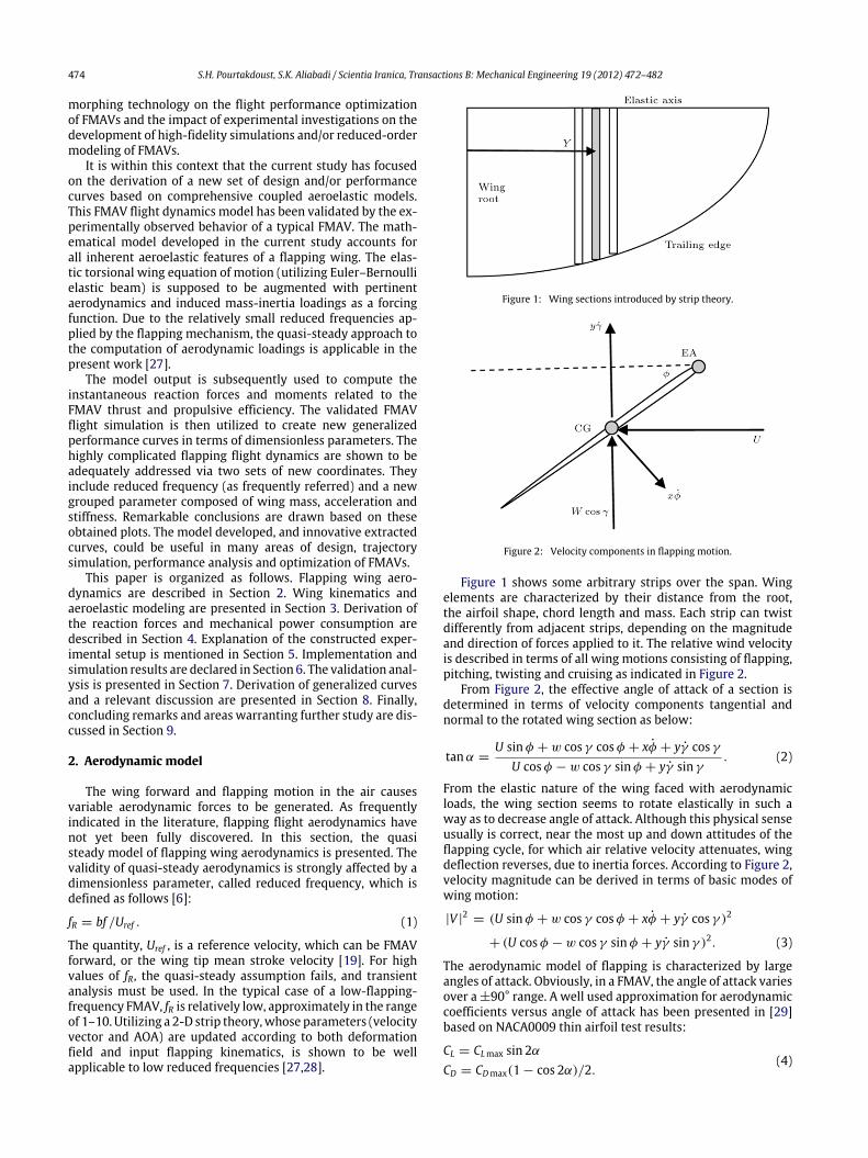
Figure 2: Velocity components in flapping motion.
Figure 1 shows some arbitrary strips over the span. Wingelements are characterized by their distance from the root,the airfoil shape, chord length and mass. Each strip can twistdifferently from adjacent strips, depending on the magnitudeand direction of forces applied to it. The relative wind velocityis described in terms of all wing motions consisting of flapping,pitching, twisting and cruising as indicated in Figure 2.
From Figure 2, the effective angle of attack of a section isdetermined in terms of velocity components tangential andnormal to the rotated wing section as below:
tanα =U sinφ + w cos γ cosφ + xφ̇ + yγ̇ cos γ
U cosφ − w cos γ sinφ + yγ̇ sin γ. (2)
From the elastic nature of the wing faced with aerodynamicloads, the wing section seems to rotate elastically in such away as to decrease angle of attack. Although this physical senseusually is correct, near the most up and down attitudes of theflapping cycle, for which air relative velocity attenuates, wingdeflection reverses, due to inertia forces. According to Figure 2,velocity magnitude can be derived in terms of basic modes ofwing motion:
|V |2
= (U sinφ + w cos γ cosφ + xφ̇ + yγ̇ cos γ )2
+ (U cosφ − w cos γ sinφ + yγ̇ sin γ )2. (3)
The aerodynamic model of flapping is characterized by largeangles of attack. Obviously, in a FMAV, the angle of attack variesover a ±90° range. A well used approximation for aerodynamiccoefficients versus angle of attack has been presented in [29]based on NACA0009 thin airfoil test results:
CL = CLmax sin 2αCD = CDmax(1 − cos 2α)/2.
(4)
S.H. Pourtakdoust, S.K. Aliabadi / Scientia Iranica, Transactions B: Mechanical Engineering 19 (2012) 472–482 475
Figure 3: Schematic of wing flapping mechanism.
The closed form of Eq. (4) has 7% relative error in the α =
20 deg (max error). Parameters CLMax and CDMax are stronglyrelated to wing material and configuration; therefore, they canbe measured or estimated via test results.
3. Wing aeroelastic model
The purpose of FMAV aeroelastic modeling is to determinethe instantaneous wing deformations and net forces producedby flapping in terms of all kinematic parameters and flightconditions. The inputs of this model include mechanicalproperties, flight conditions and kinematic parameters. Theoutputs of the desiredmodel should consist of wing deflections,effective angle of attack, instantaneous forces and total wingacceleration.
The flapping mechanism provides the required periodicmotion of the wings. It contains a few links and joints thatproduce the wings’ harmonic motion. The wings’ cyclic motionis composed of upstroke and downstrokemovements. A typical4-bar flapping mechanism is shown in Figure 3. As can beobserved, when the gear is rotated, the wing spar goes upand down, due to runner link rotation and translation. Theflapping angle profile can be determined versus themechanismdimension. The most up and down positions of the runnerlink correspond to the flapping strokes. While the gear angularvelocity is constant, it can be shown that the flapping profile(the second link orientation), approximately, is:
γ =(γUp − γDn)
2sin(2π ft) +
(γUp + γDn)
2. (5)
In [30], the exact solution of the mechanism output iscomputed, and the error of using the harmonic profile of Eq.(5) is shown to be less than 5%. Parameters γUp and γDn arefunctions of length, L1, L2 and L4. In the constructed FMAV, themechanismdimensionsmentioned in Table 1 are sized based on30° flapping amplitude. The angular velocity and acceleration ofthe wing spar are:
γ̇ = π f (γUp − γDn) cos (2π ft)
γ̈ = −π2f 2(γUp − γDn) sin(2π ft).(6)
A simple study of wing aeroelasticity shows that for extremevalues of stiffness (0 or ∞), the obtainable thrust will be closeto zero. Neither a fully deformed membrane nor rigid wing cangenerate useful force. Obviously, an optimum coefficient canbe found through the aeroelastic model of the flapping wing.Before the equations are proposed, some basic assumptions arementioned:
1. Assume cruise condition with constant velocity;2. Linear elastic torsional deformation (Euler–Bernoulli Beam);3. Quasi-steady aerodynamic model;
Table 1: Constructed FMAV specifications.
Parameter Value Unit
b 100 CmS 1400 Cm2
C 14 CmAR 7.14 –L 35 CmL1 34 mmL2 14 mmL3 38 mmL4 12 mmγUp 30 DegγDn 30 DegΓ 60 Degf 0–10 HzU 2–8 m/sMT 230 gm 28 gρ 0.2 Kg/m2
GJ 25 Ncm2
d 1.4 mmρAir 1.2 Kg/m3
n 4 –XCG C/2 –XEA 0 –CLMax 1.2 –CDMax 2 –
4. Location of elastic axis on the L.E.;5. Harmonic trajectory of wing.
In fact, FMAV wing structures are inherently anisotropic dueto their membrane vein configurations. The spanwise bendingstiffness is approximately 1–2 orders of magnitude larger thanthe chordwise bending stiffness in a majority of reporteddesigns, as well as in the current study.
A free-body diagram for a typical wing section is depictedin Figure 4. The inertia-mass components, as well as theaerodynamic and elastic forces, are shown. The inertial forcecomponents are assumed to be exerted on CG, while theaerodynamic and internal elastic forces are exerted on ACand EA, respectively. The equation of torsional deformationof the wing section can be derived based on the augmentedEuler–Bernoulli elastic beam theory:
IY φ̈ = GJφ′′+ ρcxγ̈ y cosφ −
12(x − c/4)cV 2ρAirCL cosα
−12(x − c/4)cV 2ρAirCD sinα +
12ρgc2 cosφ cos γ . (7)
This nonlinear 2nd-order PDE describes the temporal andspatial variation of the wing twist angle. Eliminating the effectof weight, which corresponds to a constant deflection, one cansimplify the equation of motion:
IY φ̈ = GJφ′′+ ρcxγ̈ y cosφ
−12(c/4)cV 2ρAir(CL cosα + CD sinα). (8)
Parameters α and V are computed according to Eqs, (2) and(3), respectively.Many computational considerations, aswell asnumerical techniques, must be taken to solve this PDE. Furtherdiscussions are presented in Section 4.
4. Propulsion model
Derivation of the axial and normal forces acting on an FMAVduring flapping is considered in this section. The existenceof various acceleration components causes the wing overall

476 S.H. Pourtakdoust, S.K. Aliabadi / Scientia Iranica, Transactions B: Mechanical Engineering 19 (2012) 472–482
Figure 4: Free-body diagram of a wing section.
forces to be different from the applied aerodynamic or inertialforces. The reaction forces and moments on the hinge point areto be computed. Forces are considered to be functions of thewing independent rotations, γ and ϕ. According to Figure 4,contribution of a wing strip to the axial reaction force is:dFXdy
= −ρcxφ̈ sinφ − ρcxφ̇2 cosφ +12cV 2ρAir
× [CL sin(α − φ) − CD cos(α − φ)] . (9)In this equation, FX is the thrust force generated instantly bywing flapping. The rotation angle (α − ϕ) refers to the relativeattitude of the velocity vector and wing root axis. The angularacceleration induced by the wing flapping mechanism is alsoaccounted for in the above equation. Derivation of the normalforce (Lift) component after simplification gives:dFZdy
= ρcyγ̇ 2 sin γ +12ρV 2c
× [CL cos(α − φ) + CD sin(α − φ)] cos γ
+−ρcyγ̈ + ρcxφ̈ cosφ − ρcxφ̇2 sinφ
cos γ . (10)
To determine the overall lift and thrust forces over a half span,one may use simple integration:
FZ (t) =
dFZdy
dy
FX (t) =
dFXdy
dy.(11)
A significant performance index for FMAVs is the powerconsumed, which affects battery usage and, consequently,flight endurance. There are interesting issues regarding thepower consumption in FMAVs. In fact, neither increasing nordecreasing input power will lead to better performance. Theeffects of mass distribution, flapping profile, elasticity andgeometry, all together, will specify how the power varies.Referring to Figure 4, the moment applied to the wing will be:
M =
12ρV 2c(CL cos(α − φ) + CD sin(α − φ))
− ρcyγ̈ + ρcxφ̈ cosφ − ρcxφ̇2 sinφ
ydy. (12)
The mechanical power input to the wing is therefore:
P =
12ρV 2c(CL cos(α − φ) + CD sin(α − φ))
− ρcyγ̈ + ρcxφ̈ cosφ − ρcxφ̇2 sinφ
γ̇ ydy. (13)
Figure 5: Constructed FMAV and its main parts.
It should be noted that the above equation indicates themechanical power input to the wing via the link rod. It doesnot account for transient responses of the electric motor orthe mechanism transfer function. One may assume constantfrictional power dissipation due to rotating shafts, as well asconstant mechanism efficiency, to obtain the estimated powerusage.
5. Experimental setup
To validate the model, one needs to use and/or generateacceptable experimental data. In this regard, a typical FMAVwas designed and manufactured for this research, as shownin Figure 5. It is primarily composed of a fixed body, flappingwings, a servo-controlled tail and a flapping mechanismgear box, with an electric motor and battery. As a naturalconsequence of the flapping motion of the elastic wing, a netforward force will be produced.
The FMAV’s wing structure is composed of two main spars;one at the leading edge and several chordwise ribs made ofcarbon fibers. The wing surface is covered by a thin Mylarskin. Other specifications and dimensions are listed in Table 1.The torsional wing stiffness is highly dependent on the sparand rib thicknesses and diameters, as well as the numberand arrangements of ribs. For the purpose of this study, thewing bending stiffness was taken to be sufficiently large, soas to prevent significant elastic bending deformation. As inmost FMAVs, the wings twist up and down elastically aroundL.E.; therefore, the elastic axis can be accurately assumed tobe coincident with the leading edge. Table 1 shows the keygeometrical parameters, structural properties and some of theimportant aerodynamic and mechanical characteristics of theconstructed FMAV.
A typical wing configuration used in manufactured FMAVsis shown in Figure 6. The structure allows the wing to twistelastically over large angles; moreover, it can slightly bendwhen the applied loading increases; much more than thatpredicted for flapping.
To prepare the adequate experimental data and evaluatethe proposed analytical model, an FMAV test stand was alsoconstructed in which capability force measurement and dataacquisitionwere incorporated. Figure 7 shows the experimentalsetup. The constructed FMAV was mounted on the stand, andonce it started flapping, the loads along two perpendicular

S.H. Pourtakdoust, S.K. Aliabadi / Scientia Iranica, Transactions B: Mechanical Engineering 19 (2012) 472–482 477
Figure 6: Schematic view of wing structure.
Figure 7: Experimental setup used for FMAV test.
Figure 8: Experimental results for mean axial force.
axes were measured and received by a PC through an amplifiermodule and interface card.
In this way, the actual force applied to the body duringflapping was determined via a high-precision load sensor.Changing the input voltage, one canmeasure the average thrustproduced by flapping versus frequency, which in turn wasmeasured by a tachometer in this setup. For the FMAV usedhere, the overall thrust generated by flapping increased quasi-linearly by frequency as shown in Figure 8.
A dead band appears in the force-generating mechanism.Below a frequency of 2 Hz, the thrust gain is very little, dueto the low aerodynamic force followed by negligible wingdeformations. At frequencies above 7 Hz, the achievable thrustseems to attenuate with respect to the fitted line. At higherflapping frequencies, the wing deflection capacity seems tosaturate, and the inertial force coupling stops the growing rate.
Other experimental investigations of FMAVs agreewith currenttest results. In [31], a linear approximation is recommended toestimate thrust in terms of flapping frequency.
6. Simulation results
In the previous two sections, the aeroelastic nature of aflapping wing was studied. The equations of describing wingdeformations, as well as the model of the propulsion system,were presented. This nearly complete set of equations wasimplemented as a simulation code in MATLAB. The mainequations are:
IY φ̈ = GJφ′′+ ρcxγ̈ y cosφ
−12(c/4)cV 2ρAir(CL cosα + CD sinα)
tanα =U sinφ + w cos γ cosφ + xφ̇ + yγ̇ cos γ
U cosφ − w cos γ sinφ + yγ̇ sin γ(14)
|V |2
= (U sinφ + w cos γ cosφ + xφ̇ + yγ̇ cos γ )2
+ (U cosφ − w cos γ sinφ + yγ̇ sin γ )2.
The 2nd order nonlinear PDE has been numerically solved byimplicit spatial marching, which employs an additional internalloop to enhance the convergence rate. The correspondingboundary values and initial conditions are assumed to be:
φ(y = 0) = 0
φ′(y = b/2) = 0
φ(t = 0) =2yb
φMax
φ̇(t = 0) = 0.
(15)
One may conclude that the initial wing attitude is horizontal.The initial condition is correlated by the simple harmonicflapping angle. The boundary conditions are defined at wingroot and tip; therefore, it is a twopoint boundary valueproblem.According to Section 4, the model of the propulsion system is:
FX =
− ρcxφ̈ sinφ − ρcxφ̇2 cosφ
+12cV 2ρAir(CL sin(α − φ) − CD cos(α − φ))
dy
FZ =
ρcyγ̇ 2 sin γ +
12ρV 2c(CL cos(α − φ)
+ CD sin(α − φ)) cos γ
+ (−ρcyγ̈ + ρcxφ̈ cosφ − ρcxφ̇2 sinφ) cos γ
dy (16)
P =
12ρV 2c(CL cos(α − φ) + CD sin(α − φ))
− ρcyγ̈ + ρcxφ̈ cosφ − ρcxφ̇2 sinφ
γ̇ ydy.
Once the model is completely implemented in MATLAB, theparametric study of FMAVs will be possible via simulation.There aremany useful trade-off studieswithin the related flightdynamics of FMAVs. Due to a high degree of nonlinearity andcoupling in this problem, one may use the simulation codeeffectively to establish newdesign curves, aswell as performinga sensitivity analysis. Here, in this section, the simulation resultscorresponding to a manufactured FMAV, which is available forexperimental investigation, are presented. Some parametersused in the simulation are listed in Table 2.

478 S.H. Pourtakdoust, S.K. Aliabadi / Scientia Iranica, Transactions B: Mechanical Engineering 19 (2012) 472–482
Table 2: Simulated FMAV parameters.
Parameter Value Parameter Value
f 5 Hz Γ 60 degc 14 cm b/2 50 cmρ 0.2 Kg/m2 CRoot 20 cmx c/2 GJ 0.0025 Nm2
CDMax 2 CLMax 1.2
Figure 9: Twist angle profile in middle and tip and flapping angle.
The results of state variables and performance indices havebeen plotted versus time in four complete cycles to demon-strate the initial transient response. For wing deformation andAOA, the spanwise distribution plots have been also prepared.The flapping angle, supposedly a simple harmonic signal, is alsodepicted in the figures to show relative distortion and phase dif-ferences.
In Figure 9, variation of twist angle ϕ and flapping angle γhas been plotted for two spanwise locations: wing median andwing tip. As shown, the maximum deflection reaches 40° nearthe tip. The twist curve lags the flapping angle by approximately90°. This indicates that wing deflection is roughly proportionalto angular velocity, which in turn implies that aerodynamicforces dominate inertial forces. The nondeformation situationof the wing does not occur exactly at points of zero velocity(i.e. dead positions) and it has a lead. This is mainly dueto inertial forces, which are dominant under low-velocityconditions. Compared to the aerodynamic twist and the inertialtwist, one may conclude that the ratio of aerodynamic to massinertial forces is about 4.5.
Generally, the twist angle depends on mass distribution,wing geometry, wing flexibility, frequency and velocity, whichwere all taken into account in the proposed model. Figure 10shows the temporal variation of the angle of attack at the samespanwise location as mentioned before. The interpretation ofthe variation in the angle of attack requiresmore consideration,and seems possible after considering the twist plots. Figure 11shows that, in the vicinity of zero flapping angles, the expectedtrend of increasing AOA has been reversed. From Figure 9,this situation corresponds to a reduction in the angle of attackby the maximum wing deflection. From this aerodynamicallydetermined situation, the AOA trend seems more plausible.
Another interesting result regarding aeroelastic wing defor-mations can be obtained by looking at the span at specifiedtimes. These snapshots are shown in Figure 11. Receiving morephysical insight, wing maximum velocities, as well as maxi-mum flapping angles, have been selected. As expected, the twistangle increases towards the wing tip and reaches its maximumby crossing the wing from the horizontal position. Again, twoextreme curves corresponding to the maximum velocity (aero-dynamic force) and maximum acceleration (inertial force) can
Figure 10: Angle of attack profile for wing median and tip.
Figure 11: Spanwise torsional deflection distributions.
Figure 12: Spanwise AOA distributions.
be labeled. From Figure 11, one may pick the tip deflection val-ues of level-up and most-up curves, which are 9° and 41°, re-spectively. The ratio of aerodynamic to inertial forces can be,therefore, approximated, which is same as the value concludedfrom Figure 9. For the studied FMAV, the aerodynamic forcesare 4.5 times larger in magnitude than the inertial forces.
The same study was conducted by plotting AOA spanwisedistributions. As shown in Figure 12, in contrast to the wingdeflection, AOA does not increase continuously over the span. Itcan be related to the wing deflection capacity, as a mechanismfor reducing AOA, particularly in far span regions. The effectsof local velocity and aerodynamic versus inertial forces, aswell as local torsional deflection, can be addressed using AOAsnapshot patterns. Although the study of wing deformationsand AOA are essential in design andwing sizing, amore suitableapproach is to relate overall FMAV performance to the basicdesign variables. Since the flapping propulsor is considered,essentially, to convert input mechanical power to forwardthrust, it is, therefore, useful to plot the variation of bothforward flapping force and power consumption.
S.H. Pourtakdoust, S.K. Aliabadi / Scientia Iranica, Transactions B: Mechanical Engineering 19 (2012) 472–482 479
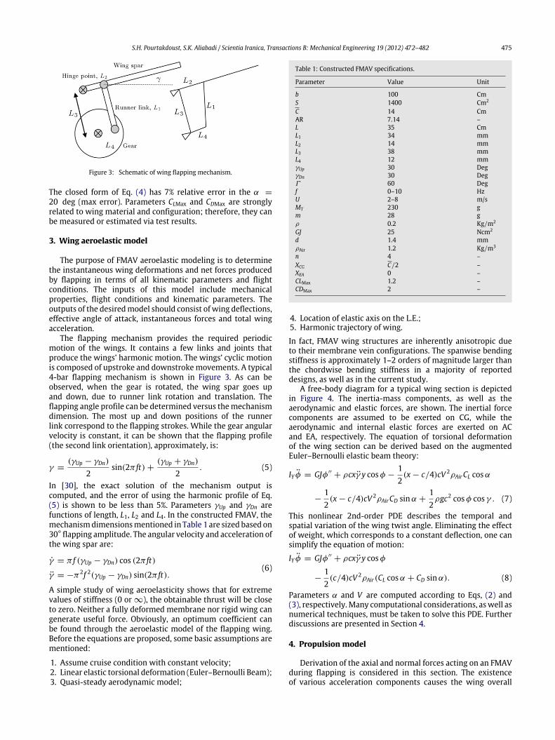
Figure 13: Overall generated lift profile.
The overall normal force produced by flapping is plottedin Figure 13. The force is computed according to Eq. (16).It shows a periodic signal averaged at zero with boundedfrequency content. A similar trend is reported in [23]. Thedeviation of the force signal from the harmonic excitationangle is essentially related to inertial and elastic forces.Regardless of whether a FMAV has fixed or rotary wings,the mass inertial forces contribute to the axial and normalforces. Although aeroelasticity causes the normal force to bedistorted, it does not change the mean value. Therefore, from aperformance point of view, embedding aeroelasticity results inlower power consumption while average lift is still zero. In thisstudy, symmetric flapping together with symmetric structure(isotropy) was assumed, which eliminated the possibility ofgenerating only net lift by flapping. From Figure 13, the phasedifference between the lift profile and flapping angle γ can alsobe estimated. This factor is useful in aeroelastic studies of FMAV,especially in optimizing wing kinematics [14].
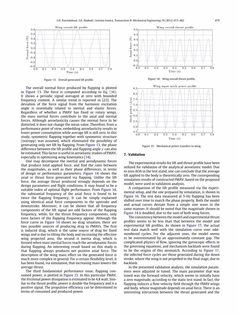
One may decompose the inertial and aerodynamic forcesthat produce total applied force, and find the ratio betweenthe magnitudes, as well as their phase differences, in termsof design or performance parameters. Figure 14 shows theaxial or thrust force generated via flapping. Unlike the liftforce, the average thrust produced strongly depends on thedesign parameters and flight conditions. It may found to be asuitable index of optimal flight performance. From Figure 14,the substantial frequency of the axial force is found to betwice the flapping frequency. It can be simply explainedusing identical axial force components in the upstroke anddownstroke. Moreover, it can be shown that all frequencycomponents of the lift signal are odd factors of the flappingfrequency, while, for the thrust frequency components, onlyeven factors of the flapping frequency appear. Although theforce curve in Figure 14 shows no drag situation, there aretwo possible sources of producing drag in FMAVs. The firstis induced drag, which is the same source of drag for fixedwings and is due to tilting the body and increasing the effectivewing projected area; the second is inertia drag, which isformedwhenmass inertial forces reach the aerodynamic forcesduring flapping. An interesting result based on this study isthat flapping always produces net positive axial force. Thedescription of the wing mass effect on the generated force ismuch more complex in general. For a certain flexibility level, ithas been found, via simulation, that increasing mass lowers theaverage thrust.
The third fundamental performance issue, flapping con-sumed power, is plotted in Figure 15. In this particular FMAV,the frictional power dissipation is estimated to be 4.8watt. Sim-ilar to the thrust profile, power is double the frequency and is apositive signal. The propulsive efficiency can be determined interms of consumed and produced power.
Figure 14: Wing overall thrust profile.
Figure 15: Mechanical power transfers to wing.
7. Validation
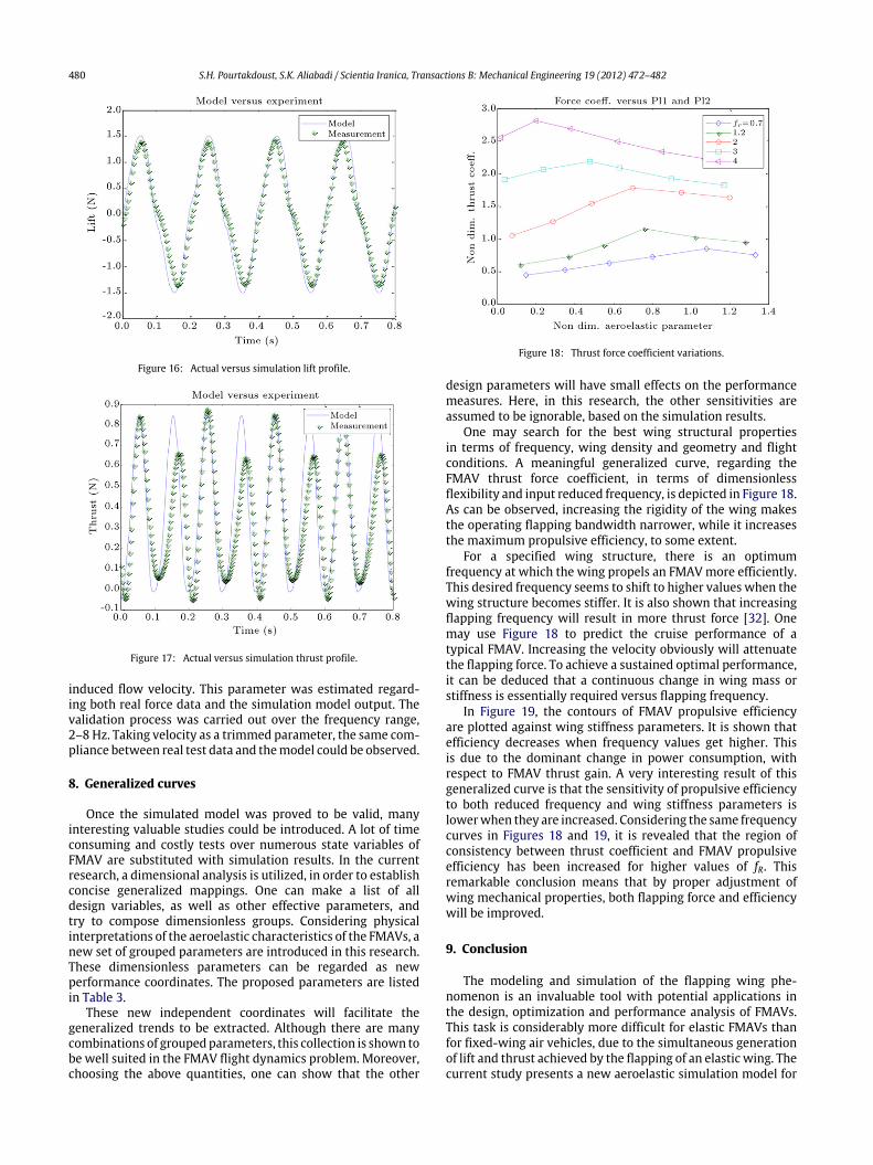
The experimental results for lift and thrust profile have beenutilized for validation of the analytical aeroelastic model. Dueto zero AOA in the test stand, one can conclude that the averagelift applied to the body is theoretically zero. The correspondingsimulation results of constructed FMAV, based on the proposedmodel, were used in validation analysis.
A comparison of the lift profile measured via the experi-mental setup, and the one prepared by simulation, is shown inFigure 16. The test data measured at 5-Hz flapping has beenshifted over time to match the phase properly. Both the modeland actual curves deviate from a simple sine wave in thesame manner. It should be noted that the magnitude shown inFigure 14 is doubled, due to the sum of both wing forces.
The consistency between themodel and experimental thrustprofiles seems to be less than that between the model andexperimental lift profiles. As shown in Figure 17, the actualtest data match well with the simulation curve over odd-numbered cycles. For the adjacent ones, the model seemsto be overestimated by an approximately constant gap. Thecomplicated physics of flow, ignoring the gyroscopic effects inthe governing equations, and mechanism backlash were foundto be the origins of this mismatch. According to Figure 17,the infected force cycles are those generated during the downstroke, where the wing is not propelled in the final stage, due tobacklash.
In the presented validation analysis, the simulation param-eters were adjusted or tuned. The main parameter that wastuned was the forward velocity, which seems to initially havea zero magnitude, according to the static test stand. In fact, theflapping induces a flow velocity field through the FMAV wingsand body, whose magnitude depends on axial force. There is aninteresting interaction between the thrust generated and the
480 S.H. Pourtakdoust, S.K. Aliabadi / Scientia Iranica, Transactions B: Mechanical Engineering 19 (2012) 472–482
Figure 16: Actual versus simulation lift profile.
Figure 17: Actual versus simulation thrust profile.
induced flow velocity. This parameter was estimated regard-ing both real force data and the simulation model output. Thevalidation process was carried out over the frequency range,2–8 Hz. Taking velocity as a trimmed parameter, the same com-pliance between real test data and themodel could be observed.
8. Generalized curves
Once the simulated model was proved to be valid, manyinteresting valuable studies could be introduced. A lot of timeconsuming and costly tests over numerous state variables ofFMAV are substituted with simulation results. In the currentresearch, a dimensional analysis is utilized, in order to establishconcise generalized mappings. One can make a list of alldesign variables, as well as other effective parameters, andtry to compose dimensionless groups. Considering physicalinterpretations of the aeroelastic characteristics of the FMAVs, anew set of grouped parameters are introduced in this research.These dimensionless parameters can be regarded as newperformance coordinates. The proposed parameters are listedin Table 3.
These new independent coordinates will facilitate thegeneralized trends to be extracted. Although there are manycombinations of groupedparameters, this collection is shown tobe well suited in the FMAV flight dynamics problem. Moreover,choosing the above quantities, one can show that the other
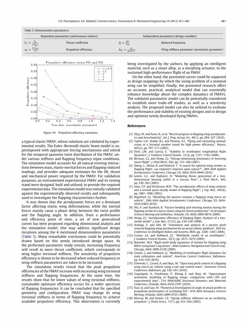
Figure 18: Thrust force coefficient variations.
design parameters will have small effects on the performancemeasures. Here, in this research, the other sensitivities areassumed to be ignorable, based on the simulation results.
One may search for the best wing structural propertiesin terms of frequency, wing density and geometry and flightconditions. A meaningful generalized curve, regarding theFMAV thrust force coefficient, in terms of dimensionlessflexibility and input reduced frequency, is depicted in Figure 18.As can be observed, increasing the rigidity of the wing makesthe operating flapping bandwidth narrower, while it increasesthe maximum propulsive efficiency, to some extent.
For a specified wing structure, there is an optimumfrequency at which the wing propels an FMAVmore efficiently.This desired frequency seems to shift to higher values when thewing structure becomes stiffer. It is also shown that increasingflapping frequency will result in more thrust force [32]. Onemay use Figure 18 to predict the cruise performance of atypical FMAV. Increasing the velocity obviously will attenuatethe flapping force. To achieve a sustained optimal performance,it can be deduced that a continuous change in wing mass orstiffness is essentially required versus flapping frequency.
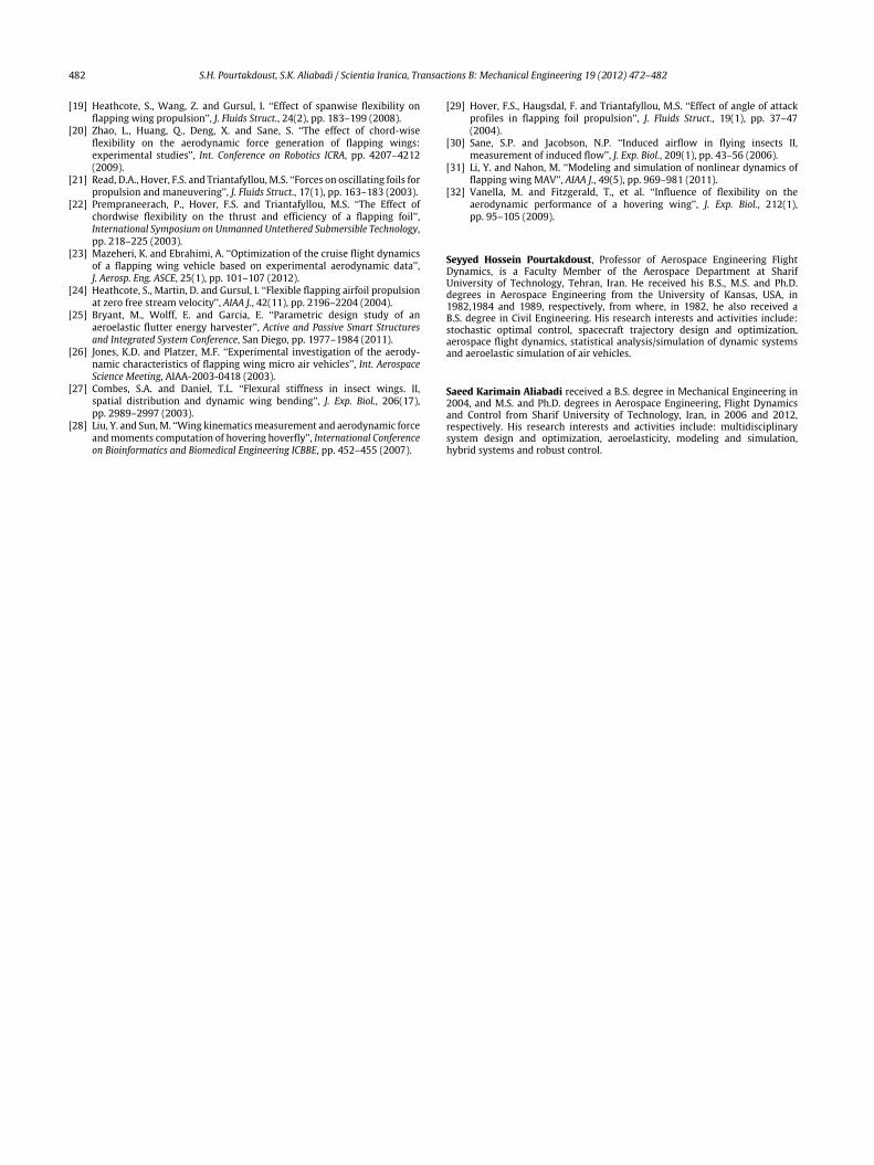
In Figure 19, the contours of FMAV propulsive efficiencyare plotted against wing stiffness parameters. It is shown thatefficiency decreases when frequency values get higher. Thisis due to the dominant change in power consumption, withrespect to FMAV thrust gain. A very interesting result of thisgeneralized curve is that the sensitivity of propulsive efficiencyto both reduced frequency and wing stiffness parameters islowerwhen they are increased. Considering the same frequencycurves in Figures 18 and 19, it is revealed that the region ofconsistency between thrust coefficient and FMAV propulsiveefficiency has been increased for higher values of fR. Thisremarkable conclusion means that by proper adjustment ofwing mechanical properties, both flapping force and efficiencywill be improved.
9. Conclusion
The modeling and simulation of the flapping wing phe-nomenon is an invaluable tool with potential applications inthe design, optimization and performance analysis of FMAVs.This task is considerably more difficult for elastic FMAVs thanfor fixed-wing air vehicles, due to the simultaneous generationof lift and thrust achieved by the flapping of an elastic wing. Thecurrent study presents a new aeroelastic simulation model for
S.H. Pourtakdoust, S.K. Aliabadi / Scientia Iranica, Transactions B: Mechanical Engineering 19 (2012) 472–482 481
Table 3: Dimensionless parameters.
Dependent parameters (performance indices) Independent parameters (design variables)
CF =FX
ρU2ref S
Thrust coefficient fR =fbΓUref
Reduced frequency
ηP =FXUref
PPropulsive efficiency kW =
GJmf 2S3/2
Wing stiffness parameter (aeroelastic parameter)
Figure 19: Propulsive efficiency variations.
a typical elastic FMAV, whose solutions are validated by exper-imental results. The Euler–Bernoulli elastic beam model is su-perimposed with appropriate forcing mechanisms and solvedfor the temporal spanwise twist distribution of the FMAV, un-der various stiffness and flapping frequency input conditions.The simulation model accounts for all natural existing interac-tions betweenmass, elasto-inertial forces and flapping-inducedloadings, and provides adequate estimates for the lift, thrustand mechanical power required by the FMAV. For validationpurposes, an instrumented experimental FMAV and its testingstand were designed, built and utilized, to provide the requiredexperimental data. The simulationmodelwas initially validatedagainst the experimentally observed results and subsequentlyused to investigate the flapping characteristics further.
It was shown that the aerodynamic forces are a dominantfactor affecting elastic wing deformations, while the inertialforces mainly cause a phase delay between the twist profileand the flapping angle. In addition, from a performanceand efficiency point of view, a set of new generalizedcurves has been proposed regarding dimensional analysis andthe simulation model. One may address significant designiterations among the 4 mentioned dimensionless parameters(Table 3). Many remarkable conclusions could be potentiallydrawn based on this newly introduced design space. Asthe performed parametric study reveals, increasing frequencywill result in more thrust coefficient, which corresponds towing higher torsional stiffness. The sensitivity of propulsiveefficiency is shown to be decreased when reduced frequency orwing stiffness parameters are taken to be increased.
The simulation results reveal that the peak propulsiveefficiencies of the FMAV increasewith increasingwing torsionalstiffness and flapping frequencies. At the same time, theresults show that for lower values of wing torsional stiffness,sustainable optimum efficiency occurs for a wider spectrumof flapping frequencies. It can be concluded that for specifiedgeometry and configuration, FMAV may change its wingtorsional stiffness in terms of flapping frequency to achieveavailable propulsive efficiency. This observation is currently
being investigated by the authors, by applying an intelligentmaterial, such as a smart alloy, as a morphing actuator, to thesustained high-performance flight of an FMAV.
On the other hand, the presented curves could be supposedas design mappings by which the sizing problem of a nominalwing can be simplified. Finally, the presented research offersan accurate, practical, analytical model that can essentiallyenhance knowledge about the complex dynamics of FMAVs.The validated parametric model can be potentially consideredto establish more trade-off studies, as well as a sensitivityanalysis. The proposed model can also be utilized to evaluatethe performance and stability of existing designs and to designand optimize newly developed flying FMAVs.
References
[1] Shyy,W. andAono, H., et al. ‘‘Recent progress in flappingwing aerodynam-ics and Aeroelasticity’’, Int. J. Prog. Aerosp. Sci., 46(1), pp. 284–327 (2010).
[2] Taylor, G.K., Nudds, R.L. and Thomas, A.L. ‘‘Flying and swimming animalscruise at a Strouhal number tuned for high power efficiency’’, Nature,425(2), pp. 707–711 (2003).
[3] Dietl, J.M. and Garcia, E. ‘‘Stability in ornithopter longitudinal flightdynamics’’, J. Guidance Control Dynam., 31(4), pp. 1157–1162 (2008).
[4] Berman, G.J. and Wang, Z.J. ‘‘Energy-minimizing kinematics in hoveringinsect flight’’, J. Fluid Mech., 582, pp. 153–168 (2007).
[5] Zheng, L., Mittal, R. and Hedrick, T. ‘‘A search for optimal wing strokes inflapping flight: can engineers improve upon nature?’’, 28th AIAA AppliedAerodynamics Conference, Chicago, US, AIAA-2010-4944 (2010).
[6] Lewin, G.C. and Hajhariri, H. ‘‘Modeling thrust generation of a two-dimensional heaving airfoil in a viscous flow’’, J. Fluid Mech., 492,pp. 339–362 (2003).
[7] Sane, S.P. and Dickinson, M.H. ‘‘The aerodynamic effects of wing rotationand a revised quasi-steady model of flapping flight’’, J. Exp. Biol., 205(8),pp. 1087–1096 (2002).
[8] Regisford, S.J. ‘‘Modeling the passive rotation a flapping wing micro airvehicle’’, 28th AIAA Applied Aerodynamics Conference, Chicago, US, AIAA-2010-4384 (2010).
[9] Wu, P. and Stanford, B. ‘‘Passive bending and twisting motion during theflapping stroke of a micro elastic wing for thrust production’’, In AerospaceSciences Meeting and Exhibition, Orlando, US, AIAA-2009-0879 (2009).
[10] Wang, Z.J. ‘‘Aerodynamic efficiency of flapping flight: Analysis of a two-stroke model’’, J. Exp. Biol., 211(2), pp. 234–238 (2008).
[11] Arabagi, V. and Sitti, M. ‘‘Simulation and analysis of a passive pitchreversal flapping wingmechanism for an aerial robotic platform’’, IEEE Int.Conference on Intelligent Robots and Systems, IROS, pp. 1260–1265 (2008).
[12] Grauer, J.A. and Hubbard, J.E. ‘‘Multibody model of an ornithopter’’,J. Guidance Control Dynam., 32(5), pp. 1675–1679 (2009).
[13] Bolender, M.A. ‘‘Rigid multi-body equations of motion for flapping wingMAVs using kane’s equations’’, AIAA Guidance, Navigation and Control Conf.,Chicago, AIAA-2009-6158 (2009).
[14] Grauer, J. and Hubbard, J.J. ‘‘Modeling of ornithopter flight dynamics forstate estimation and control’’, American Control Conference, Baltimore,pp. 524–529 (2010).
[15] Orlowski, C., Girard, A. and Shyy, W. ‘‘Open loop pitch control of a flappingwing micro-air vehicle using a tail and control mass’’, American ControlConference, Baltimore, pp. 536–541 (2010).
[16] Gogulapati, A., Friedmann, P., Kheng, E. and Shyy, W. ‘‘Approximateaeroelastic modeling of flapping wings: comparison with CFD andexperimental data’’, 51st AIAA/ASME Structural Dynamics and MaterialsConference, Orlando, AIAA-2010-2707 (2010).
[17] Xiao, Q. and Liao, W. ‘‘Numerical Investigation of angle of attack profile onpropulsion performance of oscillating foil’’, 47th AIAA Aerospace SciencesMeeting, Orlando, AIAA-2009-0725 (2009).
[18] Murray, M. and Howle, L.E. ‘‘Spring stiffness influence on an oscillatingpropulsor’’, J. Fluids Struct., 17(7), pp. 915–926 (2003).
482 S.H. Pourtakdoust, S.K. Aliabadi / Scientia Iranica, Transactions B: Mechanical Engineering 19 (2012) 472–482
[19] Heathcote, S., Wang, Z. and Gursul, I. ‘‘Effect of spanwise flexibility onflapping wing propulsion’’, J. Fluids Struct., 24(2), pp. 183–199 (2008).
[20] Zhao, L., Huang, Q., Deng, X. and Sane, S. ‘‘The effect of chord-wiseflexibility on the aerodynamic force generation of flapping wings:experimental studies’’, Int. Conference on Robotics ICRA, pp. 4207–4212(2009).
[21] Read, D.A., Hover, F.S. and Triantafyllou,M.S. ‘‘Forces on oscillating foils forpropulsion and maneuvering’’, J. Fluids Struct., 17(1), pp. 163–183 (2003).
[22] Prempraneerach, P., Hover, F.S. and Triantafyllou, M.S. ‘‘The Effect ofchordwise flexibility on the thrust and efficiency of a flapping foil’’,International Symposium on Unmanned Untethered Submersible Technology,pp. 218–225 (2003).
[23] Mazeheri, K. and Ebrahimi, A. ‘‘Optimization of the cruise flight dynamicsof a flapping wing vehicle based on experimental aerodynamic data’’,J. Aerosp. Eng. ASCE, 25(1), pp. 101–107 (2012).
[24] Heathcote, S., Martin, D. and Gursul, I. ‘‘Flexible flapping airfoil propulsionat zero free stream velocity’’, AIAA J., 42(11), pp. 2196–2204 (2004).
[25] Bryant, M., Wolff, E. and Garcia, E. ‘‘Parametric design study of anaeroelastic flutter energy harvester’’, Active and Passive Smart Structuresand Integrated System Conference, San Diego, pp. 1977–1984 (2011).
[26] Jones, K.D. and Platzer, M.F. ‘‘Experimental investigation of the aerody-namic characteristics of flapping wing micro air vehicles’’, Int. AerospaceScience Meeting, AIAA-2003-0418 (2003).
[27] Combes, S.A. and Daniel, T.L. ‘‘Flexural stiffness in insect wings. II,spatial distribution and dynamic wing bending’’, J. Exp. Biol., 206(17),pp. 2989–2997 (2003).
[28] Liu, Y. and Sun,M. ‘‘Wing kinematicsmeasurement and aerodynamic forceandmoments computation of hovering hoverfly’’, International Conferenceon Bioinformatics and Biomedical Engineering ICBBE, pp. 452–455 (2007).
[29] Hover, F.S., Haugsdal, F. and Triantafyllou, M.S. ‘‘Effect of angle of attackprofiles in flapping foil propulsion’’, J. Fluids Struct., 19(1), pp. 37–47(2004).
[30] Sane, S.P. and Jacobson, N.P. ‘‘Induced airflow in flying insects II,measurement of induced flow’’, J. Exp. Biol., 209(1), pp. 43–56 (2006).
[31] Li, Y. and Nahon, M. ‘‘Modeling and simulation of nonlinear dynamics offlapping wing MAV’’, AIAA J., 49(5), pp. 969–981 (2011).
[32] Vanella, M. and Fitzgerald, T., et al. ‘‘Influence of flexibility on theaerodynamic performance of a hovering wing’’, J. Exp. Biol., 212(1),pp. 95–105 (2009).
Seyyed Hossein Pourtakdoust, Professor of Aerospace Engineering FlightDynamics, is a Faculty Member of the Aerospace Department at SharifUniversity of Technology, Tehran, Iran. He received his B.S., M.S. and Ph.D.degrees in Aerospace Engineering from the University of Kansas, USA, in1982,1984 and 1989, respectively, from where, in 1982, he also received aB.S. degree in Civil Engineering. His research interests and activities include:stochastic optimal control, spacecraft trajectory design and optimization,aerospace flight dynamics, statistical analysis/simulation of dynamic systemsand aeroelastic simulation of air vehicles.
Saeed Karimain Aliabadi received a B.S. degree in Mechanical Engineering in2004, and M.S. and Ph.D. degrees in Aerospace Engineering, Flight Dynamicsand Control from Sharif University of Technology, Iran, in 2006 and 2012,respectively. His research interests and activities include: multidisciplinarysystem design and optimization, aeroelasticity, modeling and simulation,hybrid systems and robust control.
Copyright © 2022 FDOKUMEN