Perceptually Valid Facial Expressions for Character-Based Applications
Upload
manchesterCategory
view
0download
0
Online Submission ID: 0246
A Perceptually Validated Model for Surface Depth Hallucination
Figure 1: The leftmost and rightmost rendered images show synthetically relit textured surfaces based on albedo and surface depth acquiredfrom a single view using diffuse-lit/flash-lit image pairs. The central (novel view) rendering was generated from a single image (shown inFigure 11(a)) obtained from an online texture resource and matched to a similar exemplar for which we have recovered albedo and depthusing the image-pair method.
Abstract
Capturing depth to repesent detailed surface geometry normally re-quires expensive specialized equipment and/or collection of a largeamount of data. We introduce a practical, simple multiscale shape-from-shading method that takes diffuse-lit/flash-lit image pairs, andproduces an albedo map and textured height field that can be viewedfrom any angle under any lighting. Using two lighting conditionsenables us to subtract one from the other to estimate albedo. Inthe absence of a flash-lit image of a surface for which we alreadyhave a similar exemplar pair, we approximate albedo and diffuseshading using histogram matching. Our multiscale depth estima-tion is based on local visibility. Unlike other depth-from-shadingapproaches, all operations are performed in image space, and weimpose no constant albedo restrictions. An experimental validationshows our method works for a broad range of textured surfaces,and users are freqently unable to identify our results as syntheticin a randomized presentation. Furthermore, they are unable to de-cide between a rendering of our depth map and an equivalent onegenerated from a laser range scan in side-by-side comparisons. Wesee this method as a significant advance in acquiring surface detailfor texturing using a standard digital camera, with applications inarchitecture, archaeological reconstruction, games and special ef-fects.
CR Categories: I.3.7 [Computer Graphics]: Three-DimensionalGraphics and Realism—Color, shading, shadowing, and texture;
Keywords: relighting, shape-from-shading, albedo estimation,textured surfaces, perception, computational photography
1 Introduction
Textured surfaces such as brick, stone, wood and many other build-ing materials have local variations in their surface meso-structure.
Shading variations due to self-shadowing provide important percep-tual cues necessary to convey a correct impression of shape. Ourobjective is to produce synthetically relit results that are difficult todistinguish from photographs. (See Figure 1.) We show that an ap-proximate representation of the real surface (depth + albedo map)may be used to relight a wide range of common textured surfacesin a visually plausible manner. To this aim, we introduce a practicalmethod to recover approximate surface texture information from asingle viewpoint. We take a 2D picture and infer depth where itisn’t fully divulged in the image so we call this depth hallucination.
Assessing the effect of new buildings on lighting requires detailedmodeling of 3D geometry, materials reflectance characteristics oralbedo (equivalent to diffuse reflectance) and knowledge of light-ing conditions, so that simulations of appearance at different timesof the day are possible. Our method is aimed primarily at the mate-rials recovery part of such architectural reconstructions. However,this technique is equally applicable to recovering and representingsurface detail for use in graphically rich games and movies. Cur-rently, our method is being used to recover depth maps at a Mexicanarchaeological site [Blank for anonymity], for the production of adome-projected movie.
Our main contribution is a novel, experimentally validated shape-from-shading method, which takes diffuse-lit/flash-lit image pairsand produces a plausible textured height field that can be viewedfrom any angle under any lighting. In the absence of a flash-lit im-age, we apply histogram matching against a visually similar texturefor which we have recovered a model from diffuse-lit/flash-lit pairs.This practical optimization simplifies the capture requirements forlarge surfaces composed of the same material but containing sig-nificant meso-structure variation. To date, no published methodfor recovering and relighting textured height fields has been vali-dated against equivalent photographs. Since our goal is to recoverenough surface detail for plausible lighting, accuracy requirementsare purely perceptual and are evaluated based on the final imagery.The experimental studies we conducted demonstrate that partic-ipants cannot reliably identify our relit images as synthetic, andmore importantly that participants believe these to be as plausibleas geometrically correct laser-scanned reconstructions.
2 Previous Work
Creating 3D models directly from photographs is appealing sinceit offers the potential for simple, fast, low-cost model acquisition
1

Online Submission ID: 0246
for photorealistic visualization [Debevec et al. 1996]. However, de-tailed surface meso-structure of building materials is rarely con-sidered in such models. To correctly relight different materialsrequires separation of the way surfaces scatter light and the ac-tual light striking the surface. Although solutions to separate theseunder specific constraints have been proposed [Narasimhan et al.2003], the problem is not generally solvable. To fill in the missinginformation, humans use tacit knowledge gained from experienceof real world illumination to estimate material properties and plau-sible lighting [Fleming et al. 2003]. A number of meso-structurerecovery methods capture normal and texture maps with multiplesources [Rushmeier and Bernardini 1999; Lensch et al. 2003]. Anaccurate but data intensive approach is to capture and encode theappearance of textured surfaces with a gantry under a large numberof lighting and viewing conditions [Dana et al. 1999]. A numberof methods to recover albedo and meso-structure exist, but requiresets of images and/or need specialized equipment [Yu et al. 1999;Liu et al. 2001; Li et al. 2006; Ngan and Durand 2006; Patersonet al. 2005; Paterson and Cain 2006].
Classic shape-from-shading solutions aim to acquire 3D depth in-formation from a single image [Horn 1989; Malik and Maydan1989; Leung and Malik 2001; Prados and Faugeras 2005]. Thisis an underconstrained problem. Numerous shapes, surface re-flectances, and lighting conditions can give rise to the same shad-ing pattern [Belhumeur et al. 1999], and associated ambiguities inshape perception [Ramachandran 1988; Langer and Bulthoff 2001].However, shape-from-shading approaches are attractive for our ap-plication as they do not require special equipment or lengthy data-capture processes. Khan [2006] successfully demonstrated how,under certain circumstances, limitations in our ability to correctlyinterpret depth and lighting [Ostrovsky et al. 2005] can be exploitedto create plausible synthetic images from a dark-is-deep approxima-tion [Langer and Bulthoff 2000]. Our depth hallucination approachis inspired by their ideas.
A large body of literature on the topic of shape-from-shading exists,and we refer to published surveys for a review of existing meth-ods [Zhang et al. 1999; Durou et al. 2007]. Broadly speaking, ourapproach performs irradiance estimation and is similar in spirit tothe iterative technique of Langer and Zucker [1994]. Langer andZucker’s model is specifically designed for recovering shape-from-shading on a cloudy day. They observe that under diffuse lighting,surface luminance depends primarily on a local aperture function,which is defined as the solid angle subtended by the visible sky ateach surface point. They formulate a set of constraints, applying arobust numerical approach to solve for depth. However, there are afew practical limitations to their method. First, the model assumesuniform albedo, which is a problem for a wide range of texturedsurfaces. Second, their approach suffers from quantization sincethey perform discretized sampling of light source directions overa hemisphere at each point on a hypothetical surface. Third, theirimplementation is based on an iterative ray-tracing scheme, whichis computationally expensive. Since our goal is to recover suffi-cient depth for plausibly relighting textured surfaces, we develop asimpler, deterministic image-space solution that approximates theirresults.
3 Depth Hallucination Method
Our process is illustrated in Figure 2. The individual steps are im-age capture, albedo and shading estimation, depth estimation, andrelighting the surface. Specifics of how we estimate albedo andshading depend on whether the input to our process is a diffuse-lit/flash-lit image pair [Eisemann and Durand 2004], or a singlediffuse-lit image. Subtracting the diffuse-lit image from the flash-lit image gives a reasonable estimate of albedo, and a comparison of
Image Capture
Albedo Estimation Shading Estimation
Flash-lit/FlashCalibration Image
Diffuse Image
Depth Map Estimation
Final Render
Albedo Image
Albedo Image
DiffuseShadingImage
Depth Map
Diffuse Image
Figure 2: Flow chart showing the steps in our process.
our diffuse-lit image and albedo provides a usable estimate of dif-fuse shading for depth estimation. We discuss this in further detailin Section 3.2. Our depth estimation method is described in 3.3, andrendering of our final images is described in 3.4. Throughout thesesections, we illustrate the steps in our process with a case study ofa brick path and show the output of each intermediate step.
3.1 Image Capture
To capture our input images, we employ a standard digital SLRcamera mounted on a tripod, and an attached strobe. If the tex-tured surface contains significant specularities, cross-polarization(i.e., the polarizer on the flash is perpendicular to the polarizer onthe lens) can be used to minimize highlights [Hershberger 2008].
First we capture a RAW format image1 under indirect illumination(i.e., overcast skies or shadow). We call this the diffuse-lit condi-tion. A second photo is taken from the same point with the flashfired at full power. The camera is set to its maximum flash syn-chronization speed, while position, aperture, and focus are fixed toensure good pixel registration between the diffuse-lit and flash-litconditions. Ideally, the flash should be mounted as close to thecamera lens as possible in order to minimize shadows, though theimages shown in this paper were all taken with a standard flashmount. See Figure 3 for an example input image pair.
1We use RAW format to simplify calibrating the images to each other,however our technique also works with JPEG images if they can be lin-earized.
(a) Photograph of a brick path takenin shadowed daylight conditions.
(b) Flash-lit photograph of the brickpath.
Figure 3: An example input photograph pair.
2

Online Submission ID: 0246
(a) Derived albedo map. (b) Diffuse shading image.
Figure 4: Example albedo map and shading image generated fromthe photographs in Figure 3 of the brick path.
3.2 Albedo Map and Shading Image
The first stage in our method requires estimation of albedo and dif-fuse shading. We begin by calibrating our RAW image captures toone another based on their aperture A (f -stop), ISO I, and shutterspeed Ts and convert to linear, floating-point pixel values using thefollowing exposure correction factor (Ce):
Ce =A2
(TsI)(1)
If absolute values were required, there would be an additional con-version factor which is unnecessary for relative measurements suchas ours.
To calculate albedo Ia( j) we perform the operation expressed belowat each pixel j:
Ia( j) =I f ( j)− Id( j)
Ic( j)(2)
Pixel values in the diffuse-lit image Id are subtracted from ourflash-lit capture I f , and we divide the result by pixel values in theflash calibration image Ic taken of a white Lambertian surface ata similar distance to correct for vignetting. This yields approxi-mate reflectance values at each pixel. We apply a daylight whitebalance that provides a good match to the flash, therefore imagesubtraction results in a good color balance in our albedo image, asshown in Figure 4(a). In cases where flash shadows are present,we also apply a simple thresholding and neighbor-filling techniquethat copies detail from the flash-lit areas [Petschnigg et al. 2004].In more severe cases, we can apply an intelligent shadow removalalgorithm [Finlayson et al. 2006], though this requires some userintervention. (All examples shown in the paper used the simpler,automatic method.)
To compute the diffuse shading image, we take the ratio of thediffuse-lit condition over the albedo at each pixel. This can resultin a color cast due to skylight or cloudy illumination, but our depthestimation method uses only the luminance channel. A grayscalecomputed shading image for our brick path is shown in Figure 4.The depth estimation method described in the following section as-signs a height of 0 to a pixel intensity of 0.5, so we normalize ourshading image to this mean value.
In cases where there are significant differences in meso-structurebut similar material properties to a previously captured surface, wecan use a diffuse-lit image in conjunction with an existing diffuse-lit/flash-lit pair. We transfer the statistics of the diffuse-lit image tothe albedo and the diffuse shading image of the existing exemplarusing histogram matching [Heeger and Bergen 1995]. Figure 5(a)shows an example diffuse-lit capture taken close to the location
(a) Alternate photograph of a brickpath taken in shadow.
(b) Histogram-matched diffuse shad-ing image.
Figure 5: Example input image for histogram matching and gener-ated shading image.
shown in Figure 3(a). Figure 5(b) shows a synthesized diffuse shad-ing image computed by applying histogram matching of Figure 5(a)to Figure 4(b). The histogram matching method is especially usefulin architectural applications, where it is impractical to take flash-litimages of every portion of a large structure, but sample areas withsimilar appearance and statistics may be readily found.
3.3 Depth Estimation
The Langer and Zucker method is designed to recover shape fromshading on a cloudy day [Langer and Zucker 1994], which is pre-cisely what we capture in our technique. Applying their relaxationmethod entails iteratively ray-tracing a discretely sampled hemi-sphere of light source directions at every surface point. Instead wedevelop an approximate solution that works entirely in image spaceand yields a direct estimate of depth at each pixel. A conservativeset of assumptions ensures that we do not exaggerate depth varia-tions, and a final user-adjusted scale factor is used to achieve thedesired roughness.
Surface meso-structure can be approximated as a terrain with hillsand valleys. The orientation of the surface to the sky (cosine factor)dominates on the hills, while the visible aperture effect dominates inthe valleys, where the sides are at least partly in shadow. We there-fore begin by developing two local models to approximate thesetwo relationships between meso-structure depth and shading. Thescope of each model is shown on a hypothetical textured surface inFigure 6. These models are derived such that an above-plane linearmodel is matched to a below-plane quadratic model, at a tangentpoint, creating the smooth piecewise function plotted in Figure 7.
Below-Plane ModelWe derive our below-plane shadowing model by approximating pitsin the surface as cylinders with an aperture 2a and depth d, as shownin Figure 8(a). In order to arrive at a simple formula, we choseto ignore interreflections which we found affect the scale but notthe character of the depth estimates. We calculate an illuminationfactor Ec by integrating the cosine weighting over the solid anglesubtended by the visible sky:
Above-plane surface model applies
Below-plane surface model applies
Figure 6: Example of a profile of a textured surface and the sepa-ration between the above-plane and below-plane surface models.
3
Online Submission ID: 0246
0 0.1 0.2 0.3 0.4 0.5 0.6 0.7 0.8 0.9 1S
0
1
2
3
4
5
D
D(S)=2(1-S)D(S)=sqrt(1/S - 1)
Figure 7: The relationship between aperture and shading factor inour model. The dashed line shows the unused extensions of eachmodel.
Ec = 2π
∫θ
0cosθ
′ sinθ′dθ
′ = π sin2θ (3)
To arrive at the shading factor S we divide Ec by the illuminationfactor for the full sky, Eh which can be shown to be π .
Through simple trigonometry the integrated shading factor be-comes:
S =Ec
Eh=
π sin2θ
π=
a2
a2 +d2 (4)
Pit depth can therefore be estimated by solving Equation 4 for d as:
d = a
√1S−1 (5)
Above-Plane ModelFor the above-plane model, we approximate surface protrusions ashemispheres whose shading is a function of the visible portion ofthe hemisphere hv subtended by the solid angle ψ (Figure 8(b)) andadded to the remaining reflected portion of the hemisphere outsidethe solid angle subtended by ψ , hr. Depth can thus be estimated bya simple linear model derived as follows, where ρ is the effectivesurrounding surface reflectance.
hv =π
2(1+ cosψ) (6)
hr = ρπ
2(1− cosψ) (7)
Consequently our above-plane shading factor is calculated as theratio of these quantities and π:
S =π
2 (1+ cosψ)+ρπ
2 (1− cosψ)π
(8)
This can be simplified and solved for cosψ to give:
d
2a
2θ
(a) Cylinder pit model.
d
Rψ
(b) Hemisphere protrusion model.
Figure 8: Model to approximate shading of pits and surface pro-trusions.
cosψ =2S− (1+ρ)
1−ρ(9)
From Figure 8(b):d = R−Rcosψ (10)
Substituting cosψ gives the linear model:
d = 2R1−S1−ρ
(11)
where R is the radius of the hemispherical hill.
Combined ModelThese two models, expressed in Equations 5 and 11 can be con-veniently combined at a double root solution to their intersection,by substituting S = 1/2 and equating the corresponding values of dyielding:
a =R
(1−ρ)(12)
Again for convenience we assume the surrounding surface re-flectance ρ = 0, allowing our modeled depth to be computed fromthe shading variation at each aperture scale, a, from the combinedformula:
D(S) = d/a ={ √
1/S−1 for S ≤ 1/22(1−S) for S > 1/2
(13)
Multiscale FormulationIn a multiscale formulation of our model, the value of a is takenfrom each blur radius in a Gaussian decomposition of the diffuseshading image, ensuring an appropriate scale is used for each shad-ing feature. Starting from a normalized version of our diffuse shad-ing image, as shown in Figure 4(b), we compute several Gaussianblurred images using kernel radii (r) increasing by powers of threeup to a maximum detail size m based on image content and speci-fied by the user. At each level, the image is divided by the imageat the next largest kernel radius (upto the largest) and multiplied by1/2 for normalization, effectively yielding a Laplacian pyramid ofequal resolution images [Burt and Adelson 1983]. These blurredimages are referred to as `(i). Each of our N levels is then trans-formed using the depth function D given in Equation 13, where a isreplaced by the blur radius relative to the synthesized surface sizeat each pixel j arriving at a per pixel depth value D j:
D j =N
∑i=1
r(i)m
[D(` j(i))−1] (14)
4
Online Submission ID: 0246
(a) Rad(i) = 27. (b) Rad(i) = 9.
(c) Rad(i) = 3. (d) Rad(i) = 1.
Figure 9: The effect of different levels of Gaussian blur on the nor-malized shading image for the brick path example.
Figure 9 shows our progressively blurred shading images for thebrick path example. We subtract 1 from our computed depths ateach level since this is the normal value for D(S) at the averageimage intensity of 0.5, and we want our average surface depth to bezero.
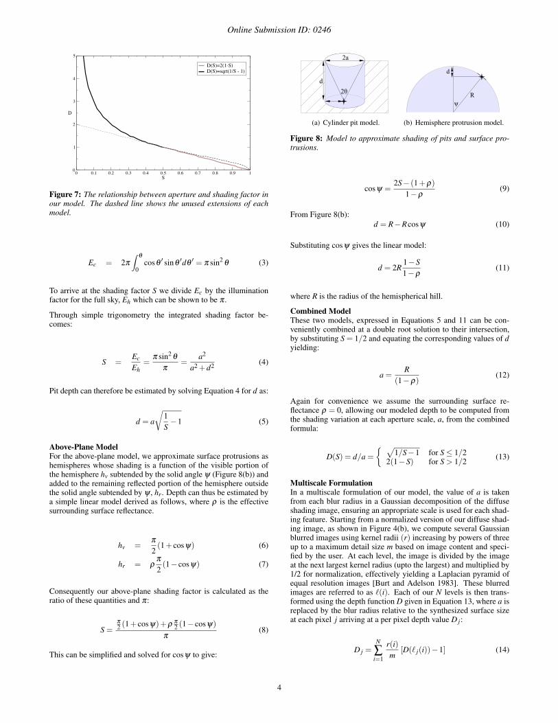
Figure 10: A comparison between a simple dark-is-deep approxi-mation and our multi-scale model.
As noted earlier, our depth estimates are conservative. First, we ig-nored albedo to simplify our analysis. Second, in the interests ofa simple combined model, we approximate indentations in the sur-face as pits, where a crevice model might be more appropriate incertain cases. We therefore apply a user-selected, uniform scalingfactor to each depth map to compensate for this and achieve an ac-ceptable visual match to the original surface appearance. For all ourtest scenes, this scaling factor was between 0.75 and 1.5. Our un-optimized implementation takes 15 seconds to generate a 900x600resolution depth map on a single core 2.5 GHz desktop computer.
(a) Rock wall image. (b) Depth map obtained using ourmodel.
Figure 11: Depth map recovered from a single image of a rock wallobtained from the Web.
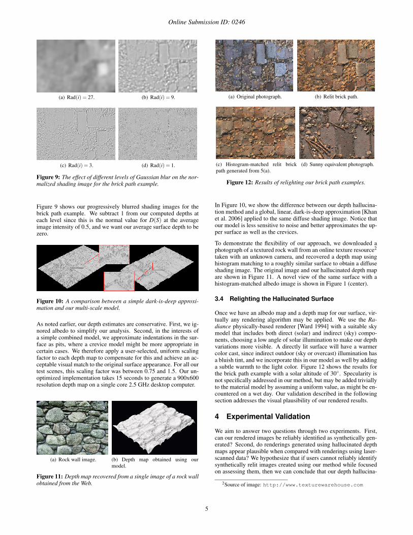
(a) Original photograph. (b) Relit brick path.
(c) Histogram-matched relit brickpath generated from 5(a).
(d) Sunny equivalent photograph.
Figure 12: Results of relighting our brick path examples.
In Figure 10, we show the difference between our depth hallucina-tion method and a global, linear, dark-is-deep approximation [Khanet al. 2006] applied to the same diffuse shading image. Notice thatour model is less sensitive to noise and better approximates the up-per surface as well as the crevices.
To demonstrate the flexibility of our approach, we downloaded aphotograph of a textured rock wall from an online texture resource2
taken with an unknown camera, and recovered a depth map usinghistogram matching to a roughly similar surface to obtain a diffuseshading image. The original image and our hallucinated depth mapare shown in Figure 11. A novel view of the same surface with ahistogram-matched albedo image is shown in Figure 1 (center).
3.4 Relighting the Hallucinated Surface
Once we have an albedo map and a depth map for our surface, vir-tually any rendering algorithm may be applied. We use the Ra-diance physically-based renderer [Ward 1994] with a suitable skymodel that includes both direct (solar) and indirect (sky) compo-nents, choosing a low angle of solar illumination to make our depthvariations more visible. A directly lit surface will have a warmercolor cast, since indirect outdoor (sky or overcast) illumination hasa bluish tint, and we incorporate this in our model as well by addinga subtle warmth to the light color. Figure 12 shows the results forthe brick path example with a solar altitude of 30◦. Specularity isnot specifically addressed in our method, but may be added triviallyto the material model by assuming a uniform value, as might be en-countered on a wet day. Our validation described in the followingsection addresses the visual plausibility of our rendered results.
4 Experimental Validation
We aim to answer two questions through two experiments. First,can our rendered images be reliably identified as synthetically gen-erated? Second, do renderings generated using hallucinated depthmaps appear plausible when compared with renderings using laser-scanned data? We hypothesize that if users cannot reliably identifysynthetically relit images created using our method while focusedon assessing them, then we can conclude that our depth hallucina-
2Source of image: http://www.texturewarehouse.com
5

Online Submission ID: 0246
(a) Rendering of hallucinated depthmap.
(b) Rendering of laser-scanneddepth map.
Figure 13: Matched lighting frames of the Venus North Platform,[blank for anonymity].
tion method recovers sufficient detail to allow us to plausibly relighttextured surfaces.
Participants with normal vision were seated in front of a standardLCD display. The experimenter ran an application which presentedhigh resolution images to each participant. For each stimulus, par-ticipants were asked to press a key to either rank the image, or tochoose between an image pair, depending on the experiment. Allcollected key-presses were logged.
4.1 Experiment One
The goal of Experiment One was to assess whether people canreliably identify images created using our depth hallucination ap-proach. Single images depicting a variety of textured surfaces, con-sisting of both real photographs and synthetically relit images, werepresented in a randomized order. (See Figure 1 and Figure 12 forexamples.) A total of 27 images were presented to each person inthis part of the study. This set contained 9 day-lit photographs,9 synthetically relit images and 9 synthetically relit histogram-matched images. Due to the difficulty in acquiring photographswith natural sunny lighting conditions at exactly the same location,the set of equivalent day-lit photographs were not necessarily takenfrom an identical view point to the images used to recover texturehallucinations. Participants were asked to rank each image from1 to 5, corresponding to their certainty that the image they wereviewing was an untouched photograph. On this scale, we define1 as definitely synthetically generated, and 5 as definitely an un-touched photograph. The duration for which each image was dis-played was determined via a pilot study involving 20 participants inwhich stimuli were presented for 1, 3 and 5 seconds. We found nosignificant differences in people’s ratings between images shownfor given time intervals. Study data was collected for experimentone from a new set of 20 participants who were shown each stimu-lus for 3 seconds.
4.2 Experiment Two
Our second study was a two-alternative forced-choice experimentin which the aim was to evaluate our estimated depth maps relativeto ground-truth data. Twelve pairs of still image frames from ananimation depicting changing solar position over the scene with afixed viewpoint (but novel to the captured one) were used. Eachimage pair contained an image frame created using ground truthgeometry acquired through a laser scanning process, and an equiv-alent image frame generated using our technique for estimating thedepth map from photographs. The same albedo map was registeredto both the laser-scan and hallucinated depth maps, and the samephysically-based rendering method was used for relighting both se-quences. No in-filling techniques were applied to the laser-scan.The lighting frame was matched for specific image pairs (similar
to those shown in Figure 13). However, lighting was similarly var-ied between frames in the image sequences. Within each imagepair, the laser-scanned and hallucinated surfaces were presented ina randomized order, and displayed for 3 seconds (again determinedthrough a pilot study). Participants were asked to choose the imagethey believed to be most likely to be the real surface. Study datawas collected using a completely new set of 20 participants.
5 Results and Data Analysis
In the first experiment, where participants rated how real the imageslooked, a repeated measures analysis of variance (ANOVA) showeda slight preference for the photographs (F2,38 = 21.61, p<0.001).Unsurprisingly since reproducing the subtle effects captured in aphotograph is a major challenge, this difference was statisticallysignificant [TODO - effect size!]. An important result however isthat on a scale of 1 to 5: photos received a mean rating of 3.97,relit images scored 3.22 for models derived with diffuse-lit/flash-lit pairs, and 2.98 for histogram-matched versions. The differencebetween both classes of synthetic images was not found to be sta-tistically significant. On our rating scale a value of 3 or above cor-responds to users not being able to decide whether or not the imageis a photograph.
Relit images were rarely dismissed as definitely artificial, andequivalent photographs were not always recognized as real. Forfour out of our nine test scenes, the mean scores in Figure 14(a)show that our synthetic images were virtually indistinguishablefrom equivalent photographs. In the remaining scenes, relit imageswere still not rejected outright. Importantly Figure 14(b) showsthat around 15 out of 20 participants gave our synthetic images av-erage ratings above 3, leading us to conclude that our renderingscompare very well with photographs. This is further supported byparticipants commenting in post study de-briefing, on the difficultyin determining which images were synthetic.
(a) Average ratings from 20 participants, for each specificscene.
(b) Average ratings per participant, for each class of stim-ulus.
Figure 14: Results from experiment one.
6
Online Submission ID: 0246
Figure 15: Experiment two: percentage of preferred class of stim-ulus (hallucinated or laser-scanned) per participant.
In the forced-choice experiment, a paired-sample t-test showed nosignificant difference between hallucinated depth and the laser-scan. This leads us to conclude that participants could not tellwhich of the two looked most plausible to them. Mean scores foreach choice were 54% for the hallucinated depth, and 46% for thelaser-scan. Nine participants out of 20 showed a preference for thehallucinated depth (see Figure 15), while 6 show a preference forthe renderings based on the laser-scanned data. The remaining 5seem undecided. The viewpoint for each data set was maintainedidentical across all stimuli and close to the captured view to avoidbias for or against either depth map. Within each image pair, theonly variable was the depth map used to generate the image. Ifthe view played a significant role in users’ assessments then the re-sults would have been clearly bipolar, however only 2 participantsconsistently chose a particular depth map in every comparison. Be-tween each image pair, lighting was varied. If lighting played asignificant role in biasing the results, we would not have seen con-sistent strong differences in preference between subjects.
6 Limitations
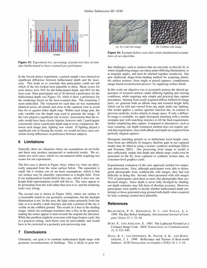
Naturally, there are situations where our assumptions do not hold,and these may produce unexpected or undesired results. We ex-amine two such cases, which we encountered while acquiring testscenes for our experiments.
The first case is shown in Figure 16(a), where ivy vines are phys-ically separated from the stone surface below. The separation issmall, but it violates one of our basic assumptions, which is thatour surface may be plausibly represented as a height field. Evenif our mathematical model held in this case, which it does not, ourheight field representation would still fail us. The vines appear tobe protruding from the wall rather than next to it, and the renderinglooks very wrong.
The second case is shown in Figure 16(b), where our surface isa reasonable match to our geometry assumptions, but the daylightillumination is not. In this area, the light comes primarily from oneside, as it is nearby a dark structure and only a portion of the sky isvisible on the cobbled ground. This results in a bias in the shadingimage, which our technique translates into a bias in the geometry,making the stones appear to lean towards the original sky direction.While this problem might be overcome with large bounce cards, butin a practical setting, such biases may be unavoidable, and wouldhave to be corrected in a geometry post-processing step.
7 Conclusions
Ultimately, our goal is to combine hallucinated depth maps withgeometry reconstructions of buildings. This is likely to pose fur-
(a) Ivy wall relit image. (b) Cobbles relit image.
Figure 16: Example failure cases that violate fundamental assump-tions of our algorithm.
ther challenges, such as surfaces that are unevenly or directly lit, orwhere neighboring images are taken under differing illumination, orat irregular angles, and must be stitched together seamlessly. Ournew multiscale shape-from-shading method for acquiring plausi-ble surface textures, from single or paired captures, complementsimage-based reconstruction process’ by supplying surface detail.
In this work our objective was to accurately portray the altered ap-pearance of textured surfaces under differing lighting and viewingconditions, while requiring only simple and practical data captureprocedures. Starting from easily acquired diffuse-lit/flash-lit imagepairs, we generate both an albedo map and textured height field,which can be relit and viewed from any angle under any lighting.Our model applies a surface aperture function but, in contrast toprevious methods, works entirely in image space. If only a diffuse-lit image is available, we apply histogram matching with a similarexemplar pair with matching statistics to lift the flash requirement,further simplifying data capture. Compared to alternatives, such aslaser scanning, our depth estimation method does not require spe-cial data registration, since both albedo and depth are acquired fromperfectly aligned captures.
Histogram matching permits us to hallucinate local height varia-tions from any diffusely lit imagery, therfore gaps in our capturedmodel may be filled-in using a texture synthesis technique [Efrosand Freeman 2001]. Our processing from image to model isalso sufficiently simple that depth and albedo maps could even begenerated on the fly, from captured or synthetic texture data, onconsumer-level graphics cards.
Experimental evaluation of this new approach yielded two impor-tant observations. First, although participants were able to distin-guish photographs from synthetically relit images, they had realdifficulty in doing this. Second, when presented with relit images75% of participants rated them as more like photographs than syn-thesized images. Since depth is never fully divulged by shading,our depth estimates may fall short of absolute accuracy. However,participants were unable to decide whether hallucinated depth ren-derings or those generated using ground truth depth values acquiredby laser scanning seemed most plausible.
References
BELHUMEUR, P. N., KRIEGMAN, D. J., AND YUILLE, A. L.1999. The Bas-Relief Ambiguity. International Journal of Com-puter Vision 35, 1, 33–44.
BURT, P., AND ADELSON, E. 1983. The Laplacian Pyramid as aCompact Image Code. IEEE Transactions on Communications31, 4, 532–540.
DANA, K. J., VAN GINNEKEN, B., NAYAR, S. K., AND KOEN-DERINK, J. J. 1999. Reflectance and Texture of Real-worldSurfaces. ACM Transactions on Graphics (TOG) 18, 1, 1–34.
7

Online Submission ID: 0246
DEBEVEC, P. E., TAYLOR, C. J., AND MALIK, J. 1996. Mod-eling and Rendering Architecture from Photographs: A HybridGeometry and Image-based Approach. In SIGGRAPH, ACM,11–20.
DUROU, J.-D., FALCONE, M., AND SAGONA, M. 2007. Nu-merical Methods for Shape-from-Shading: A New Survey withBenchmarks. Computer Vision and Image Understanding 109,1, 22–43.
EFROS, A. A., AND FREEMAN, W. T. 2001. Image Quilting forTexture Synthesis and Transfer. In SIGGRAPH, ACM, 341–346.
EISEMANN, E., AND DURAND, F. 2004. Flash Photography En-hancement via Intrinsic Relighting. In SIGGRAPH, ACM, 673–678.
FINLAYSON, G. D., HORDLEY, S., CHENG, L., AND DREW, M.2006. On the Removal of Shadows from Images. Transactionson Pattern Analysis and Machine Intelligence 28, 1, 59–68.
FLEMING, R. W., DROR, R. O., AND ADELSON, E. H. 2003.Real-World Illumination and the Perception of Surface Re-flectance Properties. Journal of Vision 3, 5, 347–368.
HEEGER, D. J., AND BERGEN, J. R. 1995. Pyramid-Based Tex-ture Analysis/Synthesis. In SIGGRAPH, ACM, 229–238.
HERSHBERGER, W., 2008. Taming those Annoying Highlights:Cross-Polarization Flash Macro Photography. Online article.http://www.naturescapes.net/042004/wh0404.htm.
HORN, B. K. P. 1989. Obtaining Shape from Shading Informa-tion. In Series of Artificial Intelligence: Shape from Shading.Mit Press, Cambridge, MA, 123–171.
KHAN, E. A., REINHARD, E., FLEMING, R. W., ANDBULTHOFF, H. H. 2006. Image-based Material Editing. InSIGGRAPH, ACM, 654–663.
LANGER, M. S., AND BULTHOFF, H. H. 2000. Depth Discrim-ination from Shading under Diffuse Lighting. Perception 29, 6,649–660.
LANGER, M. S., AND BULTHOFF, H. H. 2001. A Prior for GlobalConvexity in Local Shape-from-Shading. Perception 30, 4, 403–410.
LANGER, M. S., AND ZUCKER, S. W. 1994. Shape-from-Shadingon a Cloudy Day. Journal of the Optical Society of America 11,2, 467–478.
LENSCH, H. P. A., KAUTZ, J., GOESELE, M., HEIDRICH, W.,AND SEIDEL, H.-P. 2003. Image-based Reconstruction of Spa-tial Appearance and Geometric Detail. ACM Transactions onGraphics (TOG) 22, 2, 234–257.
LEUNG, T., AND MALIK, J. 2001. Representing and Recognizingthe Visual Appearance of Materials using Three-DimensionalTextons. International Journal of Computer Vision 43, 1, 29–44.
LI, H., FOO, S.-C., TORRANCE, K. E., AND WESTIN, S. H.2006. Automated Three-axis Gonioreflectometer for ComputerGraphics Applications. Optical Engineering 45, 4, 1–11.
LIU, X., YU, Y., AND SHUM, H.-Y. 2001. Synthesizing Bidi-rectional Texture Functions for Real-World Surfaces. In SIG-GRAPH, ACM, 97–106.
MALIK, J., AND MAYDAN, D. 1989. Recovering Three-Dimensional Shape from a Single Image of Curved Objects.
IEEE Transactions on Pattern Analysis and Machine Intelligence11, 6.
NARASIMHAN, S. G., VISVANATHAN, R., AND NAYAR, S. K.2003. A Class of Photometric Invariants: Separating Materialfrom Shape and Illumination. In ICCV, IEEE, 1387–1394.
NGAN, A., AND DURAND, F. 2006. Statistical Acquisition ofTexture Appearance. In Eurographics Symposium on Render-ing, T. Akenine-Moller and W. Heidrich, Eds. The EurographicsAssociation, 31–40.
OSTROVSKY, Y., CAVANAGH, P., AND SINHA, P. 2005. Perceiv-ing Illumination Inconsistencies in Scenes. Perception 34, 11,1301–1314.
PATERSON, J., AND CAIN, K. 2006. Efficient Field Capture ofEpigraphy via Photometric Stereo. In Virtual Reality Archae-ology and Cultural Heritage (VAST), M. Ioannides, D. Arnold,F. Niccolucci, and K. Mania, Eds., 159–161.
PATERSON, J. A., CLAUS, D., AND FITZGIBBON, A. W. 2005.BRDF and Geometry Capture from Extended InhomogeneousSamples Using Flash Photography. In Computer Graphics Fo-rum, vol. 24, Eurographics, 383–391.
PETSCHNIGG, G., SZELISKI, R., AGRAWALA, M., COHEN, M.,HOPPE, H., AND TOYAMA, K. 2004. Digital Photography withFlash and No-flash Image Pairs. In SIGGRAPH, ACM, 664–672.
PRADOS, E., AND FAUGERAS, O. 2005. Shape From Shading: AWell-posed Problem? In Computer Vision and Pattern Recogni-tion (CVPR), IEEE, 870–877.
RAMACHANDRAN, V. S. 1988. Perception of Shape from Shading.Nature, 331, 163–166.
RUSHMEIER, H., AND BERNARDINI, F. 1999. Computing Con-sistent Normals and Colors from Photometric Data. In SecondConference on 3-D Imaging and Modeling 3DIM, IEEE, 99–108.
WARD, G. J. 1994. The RADIANCE Lighting Simulation andRendering System. In SIGGRAPH, ACM, 459–72.
YU, Y., DEBEVEC, P., MALIK, J., AND HAWKINS, T. 1999. In-verse Global Illumination: Recovering Reflectance Models ofReal Scenes from Photographs. In SIGGRAPH, ACM, 215–224.
ZHANG, R., TSAI, P.-S., CRYER, J. E., AND SHAH, M. 1999.Shape from Shading: A Survey. IEEE Transactions on PatternAnalysis and MAchine Intelligence 21, 8, 690–706.
8
Copyright © 2022 FDOKUMEN