Virtual Testing with Validated Analysis Tools
12
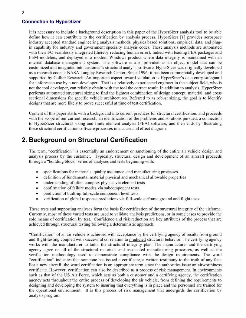
Published with permission by the NATO AVT symposium in Paris, France, April 2002. Virtual Testing with Validated Analysis Tools Craig Collier Collier Research Corporation 45 Diamond Hill Rd. Hampton, Virginia 23666 [email protected] Duane Veley Air Force Research Lab Wright-Patterson AFB, Ohio Steve Owens Lockheed Martin Aeronautics Company Fort Worth, Texas Abstract Collier Research Corporation is working with Lockheed Martin Aeronautics (LM Aero) under United States Air Force Research Lab (AFRL) funding to develop a “certification-by-analysis” process to reduce unexpected failures during experimental testing that will, in turn, accelerate Air Force structural certification. The goal is early identification and avoidance of conceptual and preliminary design problems on new and sustaining aircraft programs using a “design-by-analysis” process that includes the commercial structural sizing software called HyperSizer®. 1. Introduction Aerospace structures are certified with a combination of tests and analyses. Traditionally, and in the foreseeable future, tests serve two primary purposes: • For certifying a specific hardware architecture that can support its identified worst case design-to loads • For certifying the analysis methods and tools, which are then used to certify the untested load cases Unlike unique hardware architectures, analysis tools benefit from a history of testing in that all previous test correlations can and should collectively contribute to increased confidence of their use. Analysis tools have and will continue to play an essential role in structural certification. This paper suggests a way to improve reliability of analysis tools so that eventually the aerospace industry will be able to reduce specific architecture testing which accounts for 25–30% of product costs. This paper is not focused on the evaluation of analysis methods, but rather on how to increase confidence in the predictions made with any given analysis method and the software that implements it. Described is an analysis building-block approach for verification and validation (V&V), which parallels conventional building-block testing processes. A building block analysis verification process is a systematic way to validate specific analysis method cases, verify implementation in the software tool, calibrate prediction to test data, and establish failure data scatter as PDF’s (probability density functions) from tests for probabilistic analyses. Also described is a process for gaining more benefit from analysis tools by automating their use in conceptual and preliminary design phases. This aspect of minimizing design cycle time is most important since it accounts for 40–50% of product development costs. The objective is to deploy analysis tools as soon as reasonable in the design phase to make the biggest impact on the design progression. Referred to as design-by-analysis, this process provides beneficial early identification and avoidance of conceptual and preliminary design problems that could become extremely expensive to remedy in the final design cycle. In this way, Virtual testing is continuous throughout the design progression, and confidence is maintained in being able to successfully certify structure at time of testing - with no unpleasant surprises.
-
Upload
myohecampus -
Category
Documents
-
view
0 -
download
0
Transcript of Virtual Testing with Validated Analysis Tools
Published with permission by the NATO AVT symposium in Paris, France, April 2002.
Virtual Testing with Validated Analysis Tools
Craig Collier Collier Research Corporation
45 Diamond Hill Rd. Hampton, Virginia 23666
Duane Veley Air Force Research Lab
Wright-Patterson AFB, Ohio
Steve Owens Lockheed Martin Aeronautics Company
Fort Worth, Texas
Abstract
Collier Research Corporation is working with Lockheed Martin Aeronautics (LM Aero) under United States Air Force Research Lab (AFRL) funding to develop a “certification-by-analysis” process to reduce unexpected failures during experimental testing that will, in turn, accelerate Air Force structural certification. The goal is early identification and avoidance of conceptual and preliminary design problems on new and sustaining aircraft programs using a “design-by-analysis” process that includes the commercial structural sizing software called HyperSizer®.
1. Introduction Aerospace structures are certified with a combination of tests and analyses. Traditionally, and in the foreseeable future, tests serve two primary purposes:
• For certifying a specific hardware architecture that can support its identified worst case design-to loads • For certifying the analysis methods and tools, which are then used to certify the untested load cases
Unlike unique hardware architectures, analysis tools benefit from a history of testing in that all previous test correlations can and should collectively contribute to increased confidence of their use. Analysis tools have and will continue to play an essential role in structural certification. This paper suggests a way to improve reliability of analysis tools so that eventually the aerospace industry will be able to reduce specific architecture testing which accounts for 25–30% of product costs. This paper is not focused on the evaluation of analysis methods, but rather on how to increase confidence in the predictions made with any given analysis method and the software that implements it. Described is an analysis building-block approach for verification and validation (V&V), which parallels conventional building-block testing processes. A building block analysis verification process is a systematic way to validate specific analysis method cases, verify implementation in the software tool, calibrate prediction to test data, and establish failure data scatter as PDF’s (probability density functions) from tests for probabilistic analyses. Also described is a process for gaining more benefit from analysis tools by automating their use in conceptual and preliminary design phases. This aspect of minimizing design cycle time is most important since it accounts for 40–50% of product development costs. The objective is to deploy analysis tools as soon as reasonable in the design phase to make the biggest impact on the design progression. Referred to as design-by-analysis, this process provides beneficial early identification and avoidance of conceptual and preliminary design problems that could become extremely expensive to remedy in the final design cycle. In this way, Virtual testing is continuous throughout the design progression, and confidence is maintained in being able to successfully certify structure at time of testing - with no unpleasant surprises.
2
Connection to HyperSizer It is necessary to include a background description in this paper of the HyperSizer analysis tool to be able define how it can contribute to the certification by analysis process. HyperSizer [1] provides aerospace industry accepted standard engineering analysis methods, physics based solutions, empirical data, and plug-in capability for industry and government specialty analysis codes. These analysis methods are automated with their I/O seamlessly integrated (thereby reducing human error), linked with leading FEA packages and FEM modelers, and deployed in a modern Windows product where data integrity is maintained with an internal database management system. The software is also provided as an object model that can be customized and integrated into customer’s structural analysis software. HyperSizer was originally developed as a research code at NASA Langley Research Center. Since 1996, it has been commercially developed and supported by Collier Research. An important aspect toward validation is HyperSizer’s data entry safeguard for unforeseen use by a non-developer. That is a relatively experienced engineer in the subject field, who is not the tool developer, can reliably obtain with the tool the correct result. In addition to analysis, HyperSizer performs automated structural sizing to find the lightest combination of design concept, material, and cross sectional dimensions for specific vehicle architectures. Referred to as robust sizing, the goal is to identify designs that are more likely to prove successful at time of test certification. Content of this paper starts with a background into current practices for structural certification, and proceeds with the scope of our current research, an identification of the problems and solutions pursued, a connection to HyperSizer structural sizing and finite element analysis (FEA) software, and then ends by illustrating these structural certification software processes in a cause and effect diagram.
2. Background on Structural Certification
The term, “certification” is essentially an endorsement or sanctioning of the entire air vehicle design and analysis process by the customer. Typically, structural design and development of an aircraft proceeds through a “building block” series of analyses and tests beginning with:
• specifications for materials, quality assurance, and manufacturing processes • definition of fundamental material physical and mechanical allowable properties • understanding of often complex physics via element tests • confirmation of failure modes via subcomponent tests • prediction of built-up full-scale component level tests • verification of global response predictions via full-scale airframe ground and flight tests
These tests and supporting analyses form the basis for certification of the structural integrity of the airframe. Currently, most of these varied tests are used to validate analysis predictions, or in some cases to provide the sole means of certification by test. Confidence and risk reduction are key attributes of the process that are achieved through structural testing following a deterministic approach. “Certification” of an air vehicle is achieved with acceptance by the certifying agency of results from ground and flight-testing coupled with successful correlation to predicted structural behavior. The certifying agency works with the manufacturer to tailor the structural integrity plan. The manufacturer and the certifying agency agree on all of the structural materials and associated manufacturing processes, as well as the verification methodology used to demonstrate compliance with the design requirements. The word “certification” indicates that someone has issued a certificate, a written testimony to the truth of any fact. For a new aircraft, the word certification is an appropriate term since the authorities issue an airworthiness certificate. However, certification can also be described as a process of risk management. In environments such as that of the US Air Force, which acts as both a customer and a certifying agency, the certification agency acts throughout the entire process of developing the air vehicle, from defining the requirements to designing and developing the system to insuring that everything is in place and the personnel are trained for the operational environment. It is this process of risk management that undergirds the certification by analysis program.
3. Scope of Research/Approach
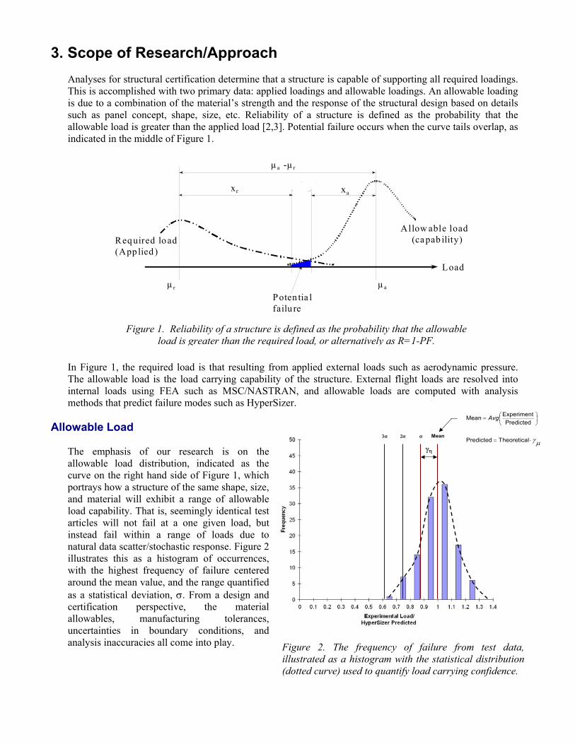
Analyses for structural certification determine that a structure is capable of supporting all required loadings. This is accomplished with two primary data: applied loadings and allowable loadings. An allowable loading is due to a combination of the material’s strength and the response of the structural design based on details such as panel concept, shape, size, etc. Reliability of a structure is defined as the probability that the allowable load is greater than the applied load [2,3]. Potential failure occurs when the curve tails overlap, as indicated in the middle of Figure 1.
In Figure 1, the required load is that resulting from applied external loads such as aerodynamic pressure. The allowable load is the load carrying capability of the structure. External flight loads are resolved into internal loads using FEA such as MSC/NASTRAN, and allowable loads are computed with analysis methods that predict failure modes such as HyperSizer.
Allowable Load The emphasis of our research is on the allowable load distribution, indicated as the curve on the right hand side of Figure 1, which portrays how a structure of the same shape, size, and material will exhibit a range of allowable load capability. That is, seemingly identical test articles will not fail at a one given load, but instead fail within a range of loads due to natural data scatter/stochastic response. Figure 2 illustrates this as a histogram of occurrences, with the highest frequency of failure centered around the mean value, and the range quantified as a statistical deviation, σ. From a design and certification perspective, the material allowables, manufacturing tolerances, uncertainties in boundary conditions, and analysis inaccuracies all come into play.
µa -µ r
xr xa
R eliab il ity
µ r µa
Poten tia lfailu re
Allow able load (ca pab ility)Required load
(App lied ) Load
Figure 1. Reliability of a structure is defined as the probability that the allowable load is greater than the required load, or alternatively as R=1-PF.
Mean
γη µγ⋅=
=
lTheoreticaPredicted
PredictedExperimentMean Avg
σ 2σ 3σ
Figure 2. The frequency of failure from test data, illustrated as a histogram with the statistical distribution (dotted curve) used to quantify load carrying confidence.
4
4. Problems Identified and Solutions Pursued
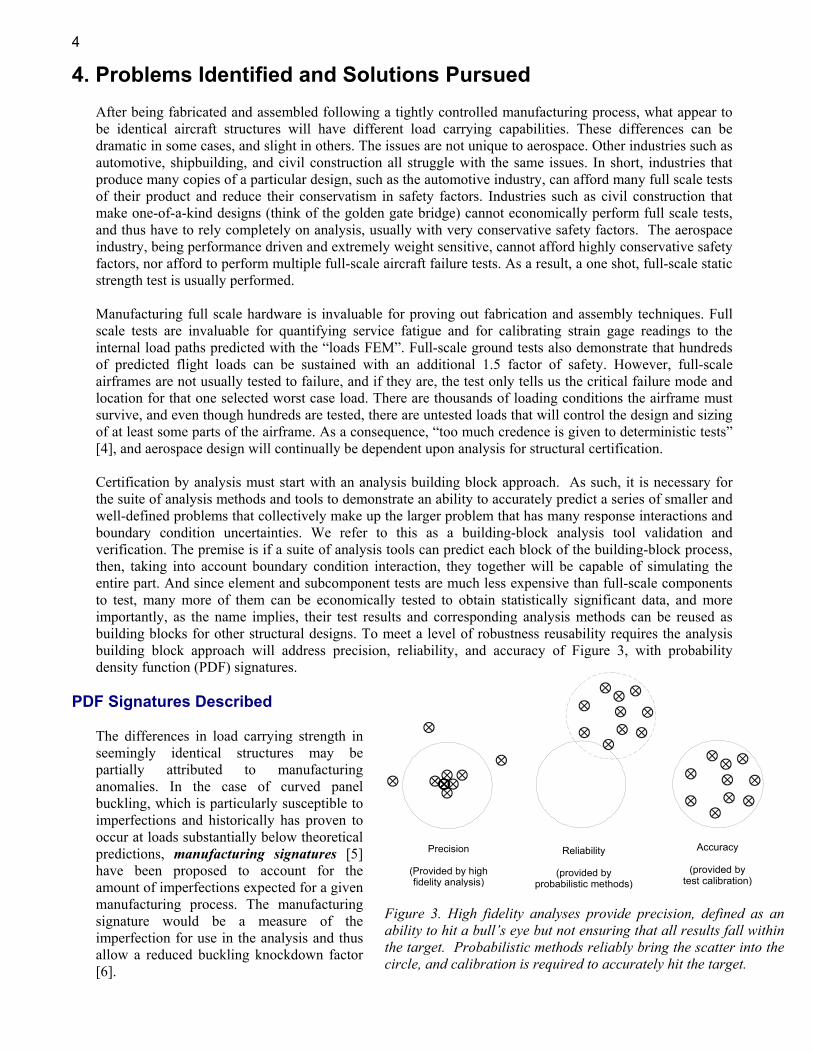
After being fabricated and assembled following a tightly controlled manufacturing process, what appear to be identical aircraft structures will have different load carrying capabilities. These differences can be dramatic in some cases, and slight in others. The issues are not unique to aerospace. Other industries such as automotive, shipbuilding, and civil construction all struggle with the same issues. In short, industries that produce many copies of a particular design, such as the automotive industry, can afford many full scale tests of their product and reduce their conservatism in safety factors. Industries such as civil construction that make one-of-a-kind designs (think of the golden gate bridge) cannot economically perform full scale tests, and thus have to rely completely on analysis, usually with very conservative safety factors. The aerospace industry, being performance driven and extremely weight sensitive, cannot afford highly conservative safety factors, nor afford to perform multiple full-scale aircraft failure tests. As a result, a one shot, full-scale static strength test is usually performed. Manufacturing full scale hardware is invaluable for proving out fabrication and assembly techniques. Full scale tests are invaluable for quantifying service fatigue and for calibrating strain gage readings to the internal load paths predicted with the “loads FEM”. Full-scale ground tests also demonstrate that hundreds of predicted flight loads can be sustained with an additional 1.5 factor of safety. However, full-scale airframes are not usually tested to failure, and if they are, the test only tells us the critical failure mode and location for that one selected worst case load. There are thousands of loading conditions the airframe must survive, and even though hundreds are tested, there are untested loads that will control the design and sizing of at least some parts of the airframe. As a consequence, “too much credence is given to deterministic tests” [4], and aerospace design will continually be dependent upon analysis for structural certification. Certification by analysis must start with an analysis building block approach. As such, it is necessary for the suite of analysis methods and tools to demonstrate an ability to accurately predict a series of smaller and well-defined problems that collectively make up the larger problem that has many response interactions and boundary condition uncertainties. We refer to this as a building-block analysis tool validation and verification. The premise is if a suite of analysis tools can predict each block of the building-block process, then, taking into account boundary condition interaction, they together will be capable of simulating the entire part. And since element and subcomponent tests are much less expensive than full-scale components to test, many more of them can be economically tested to obtain statistically significant data, and more importantly, as the name implies, their test results and corresponding analysis methods can be reused as building blocks for other structural designs. To meet a level of robustness reusability requires the analysis building block approach will address precision, reliability, and accuracy of Figure 3, with probability density function (PDF) signatures.
PDF Signatures Described
The differences in load carrying strength in seemingly identical structures may be partially attributed to manufacturing anomalies. In the case of curved panel buckling, which is particularly susceptible to imperfections and historically has proven to occur at loads substantially below theoretical predictions, manufacturing signatures [5] have been proposed to account for the amount of imperfections expected for a given manufacturing process. The manufacturing signature would be a measure of the imperfection for use in the analysis and thus allow a reduced buckling knockdown factor [6].
Accuracy
(provided bytest calibration)
Precision
(Provided by highfidelity analysis)
Reliability
(provided by probabilistic methods)
Figure 3. High fidelity analyses provide precision, defined as an ability to hit a bull’s eye but not ensuring that all results fall within the target. Probabilistic methods reliably bring the scatter into the circle, and calibration is required to accurately hit the target.
5
It seems conceivable to categorize the types of structures and loadings that will have responses fall within tight bands of results, and those that have a large amount of scatter in their behavior. These response PDF distributions can be categorized into what we call PDF signatures. By definition, PDF signatures are unique, repeatable, and, as demonstrated next, crucial for reliability based structural certification.
PDF Signature Example
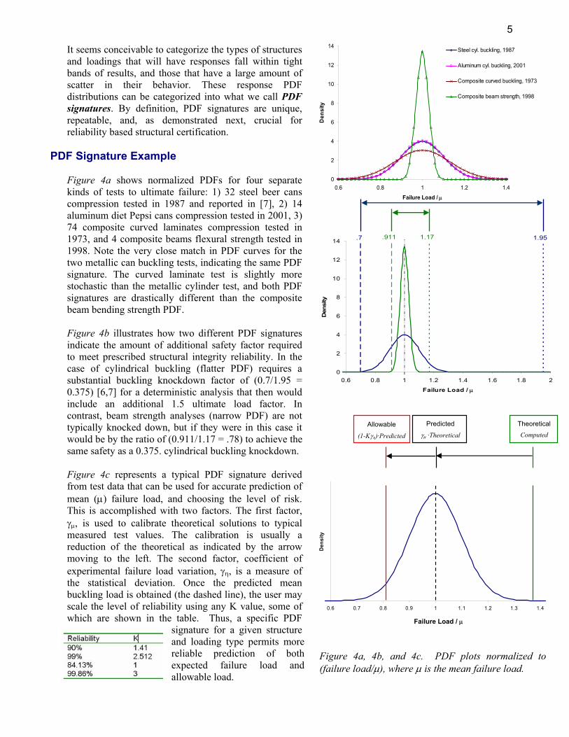
Figure 4a shows normalized PDFs for four separate kinds of tests to ultimate failure: 1) 32 steel beer cans compression tested in 1987 and reported in [7], 2) 14 aluminum diet Pepsi cans compression tested in 2001, 3) 74 composite curved laminates compression tested in 1973, and 4 composite beams flexural strength tested in 1998. Note the very close match in PDF curves for the two metallic can buckling tests, indicating the same PDF signature. The curved laminate test is slightly more stochastic than the metallic cylinder test, and both PDF signatures are drastically different than the composite beam bending strength PDF. Figure 4b illustrates how two different PDF signatures indicate the amount of additional safety factor required to meet prescribed structural integrity reliability. In the case of cylindrical buckling (flatter PDF) requires a substantial buckling knockdown factor of (0.7/1.95 = 0.375) [6,7] for a deterministic analysis that then would include an additional 1.5 ultimate load factor. In contrast, beam strength analyses (narrow PDF) are not typically knocked down, but if they were in this case it would be by the ratio of (0.911/1.17 = .78) to achieve the same safety as a 0.375. cylindrical buckling knockdown. Figure 4c represents a typical PDF signature derived from test data that can be used for accurate prediction of mean (µ) failure load, and choosing the level of risk. This is accomplished with two factors. The first factor, γµ, is used to calibrate theoretical solutions to typical measured test values. The calibration is usually a reduction of the theoretical as indicated by the arrow moving to the left. The second factor, coefficient of experimental failure load variation, γη, is a measure of the statistical deviation. Once the predicted mean buckling load is obtained (the dashed line), the user may scale the level of reliability using any K value, some of which are shown in the table. Thus, a specific PDF
signature for a given structure and loading type permits more reliable prediction of both expected failure load and allowable load.
0
2
4
6
8
10
12
14
0.6 0.8 1 1.2 1.4
Failure Load / µ
Den
sity
Steel cyl. buckling, 1987
Aluminum cyl. buckling, 2001
Composite curved buckling, 1973
Composite beam strength, 1998
0
2
4
6
8
10
12
14
0.6 0.8 1 1.2 1.4 1.6 1.8 2
Failure Load / µ
Den
sity
.911.7 1.951.17
0.6 0.7 0.8 0.9 1 1.1 1.2 1.3 1.4
Failure Load
Dens
ity
Allowable
(1-Kγη)·Predicted
Predicted
γµ ·Theoretical
TheoreticalComputed
Failure Load / µ
Figure 4a, 4b, and 4c. PDF plots normalized to (failure load/µ), where µ is the mean failure load.
6
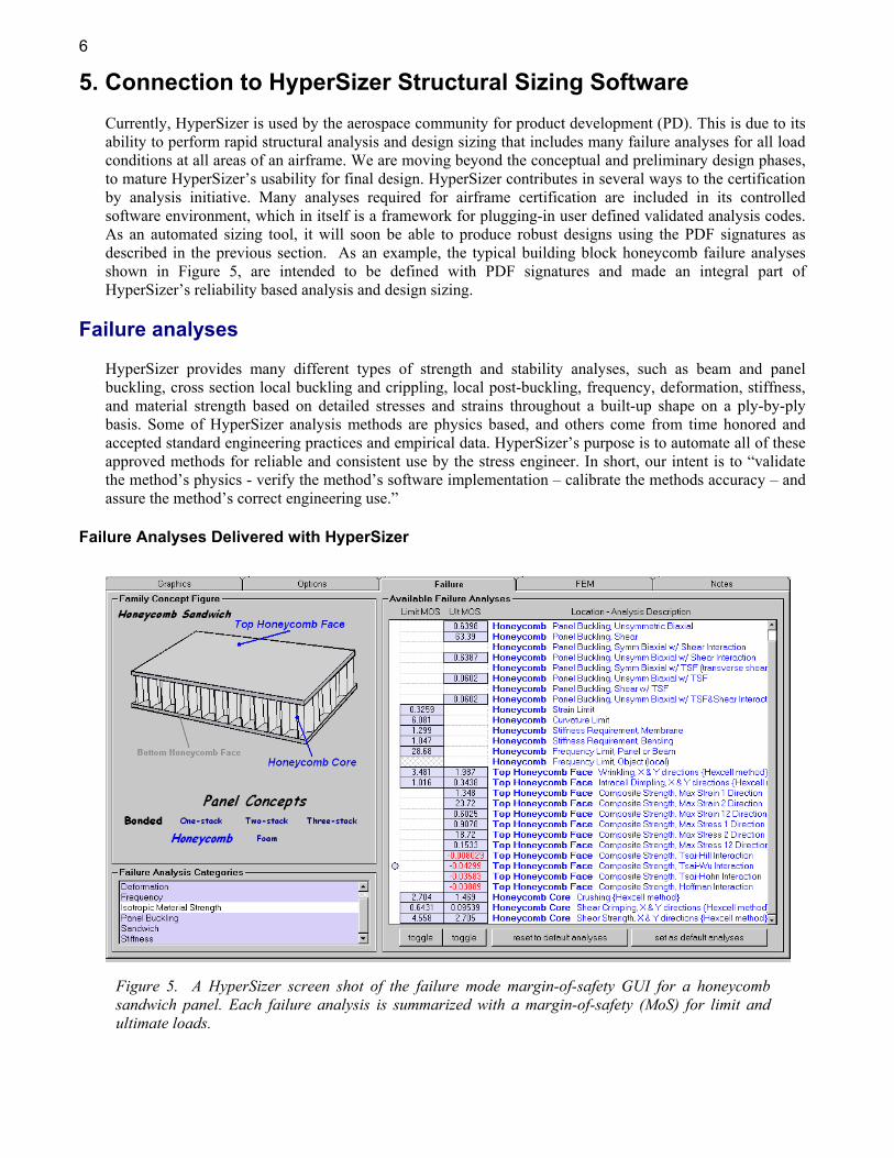
5. Connection to HyperSizer Structural Sizing Software Currently, HyperSizer is used by the aerospace community for product development (PD). This is due to its ability to perform rapid structural analysis and design sizing that includes many failure analyses for all load conditions at all areas of an airframe. We are moving beyond the conceptual and preliminary design phases, to mature HyperSizer’s usability for final design. HyperSizer contributes in several ways to the certification by analysis initiative. Many analyses required for airframe certification are included in its controlled software environment, which in itself is a framework for plugging-in user defined validated analysis codes. As an automated sizing tool, it will soon be able to produce robust designs using the PDF signatures as described in the previous section. As an example, the typical building block honeycomb failure analyses shown in Figure 5, are intended to be defined with PDF signatures and made an integral part of HyperSizer’s reliability based analysis and design sizing.
Failure analyses HyperSizer provides many different types of strength and stability analyses, such as beam and panel buckling, cross section local buckling and crippling, local post-buckling, frequency, deformation, stiffness, and material strength based on detailed stresses and strains throughout a built-up shape on a ply-by-ply basis. Some of HyperSizer analysis methods are physics based, and others come from time honored and accepted standard engineering practices and empirical data. HyperSizer’s purpose is to automate all of these approved methods for reliable and consistent use by the stress engineer. In short, our intent is to “validate the method’s physics - verify the method’s software implementation – calibrate the methods accuracy – and assure the method’s correct engineering use.”
Failure Analyses Delivered with HyperSizer
Figure 5. A HyperSizer screen shot of the failure mode margin-of-safety GUI for a honeycomb sandwich panel. Each failure analysis is summarized with a margin-of-safety (MoS) for limit and ultimate loads.
7
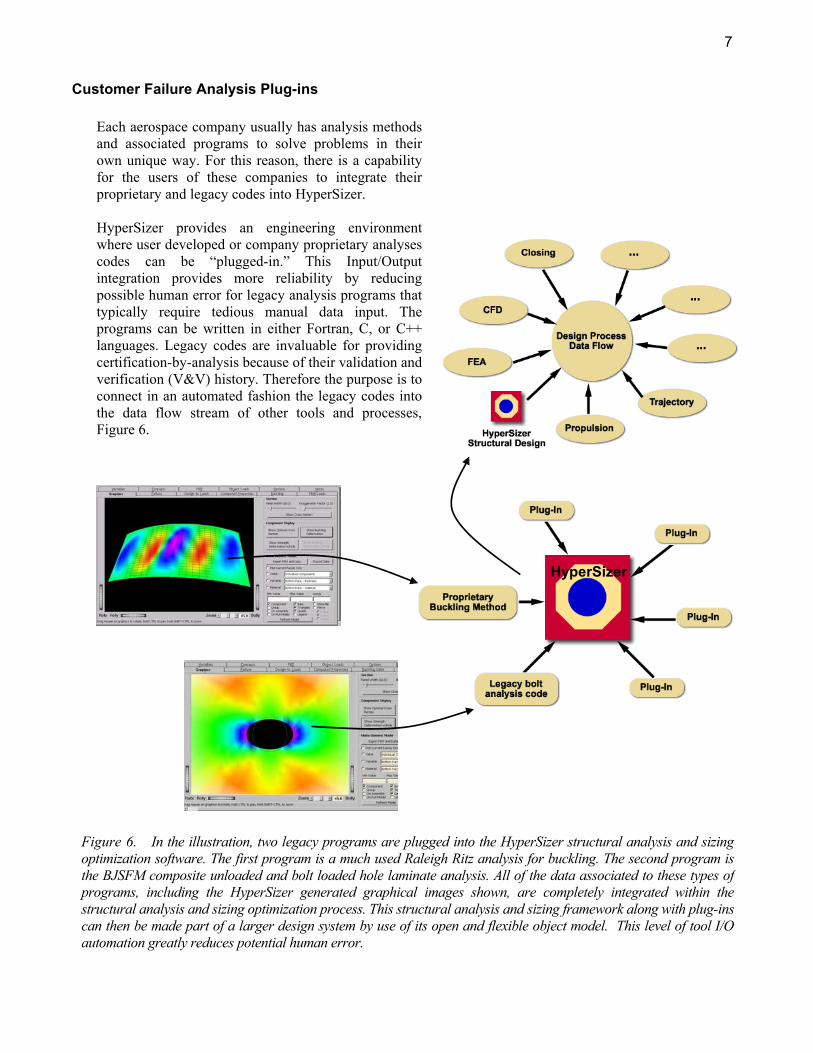
Customer Failure Analysis Plug-ins
Each aerospace company usually has analysis methods and associated programs to solve problems in their own unique way. For this reason, there is a capability for the users of these companies to integrate their proprietary and legacy codes into HyperSizer. HyperSizer provides an engineering environment where user developed or company proprietary analyses codes can be “plugged-in.” This Input/Output integration provides more reliability by reducing possible human error for legacy analysis programs that typically require tedious manual data input. The programs can be written in either Fortran, C, or C++ languages. Legacy codes are invaluable for providing certification-by-analysis because of their validation and verification (V&V) history. Therefore the purpose is to connect in an automated fashion the legacy codes into the data flow stream of other tools and processes, Figure 6.
HyperSizer
Figure 6. In the illustration, two legacy programs are plugged into the HyperSizer structural analysis and sizing optimization software. The first program is a much used Raleigh Ritz analysis for buckling. The second program is the BJSFM composite unloaded and bolt loaded hole laminate analysis. All of the data associated to these types of programs, including the HyperSizer generated graphical images shown, are completely integrated within the structural analysis and sizing optimization process. This structural analysis and sizing framework along with plug-ins can then be made part of a larger design system by use of its open and flexible object model. This level of tool I/O automation greatly reduces potential human error.
8
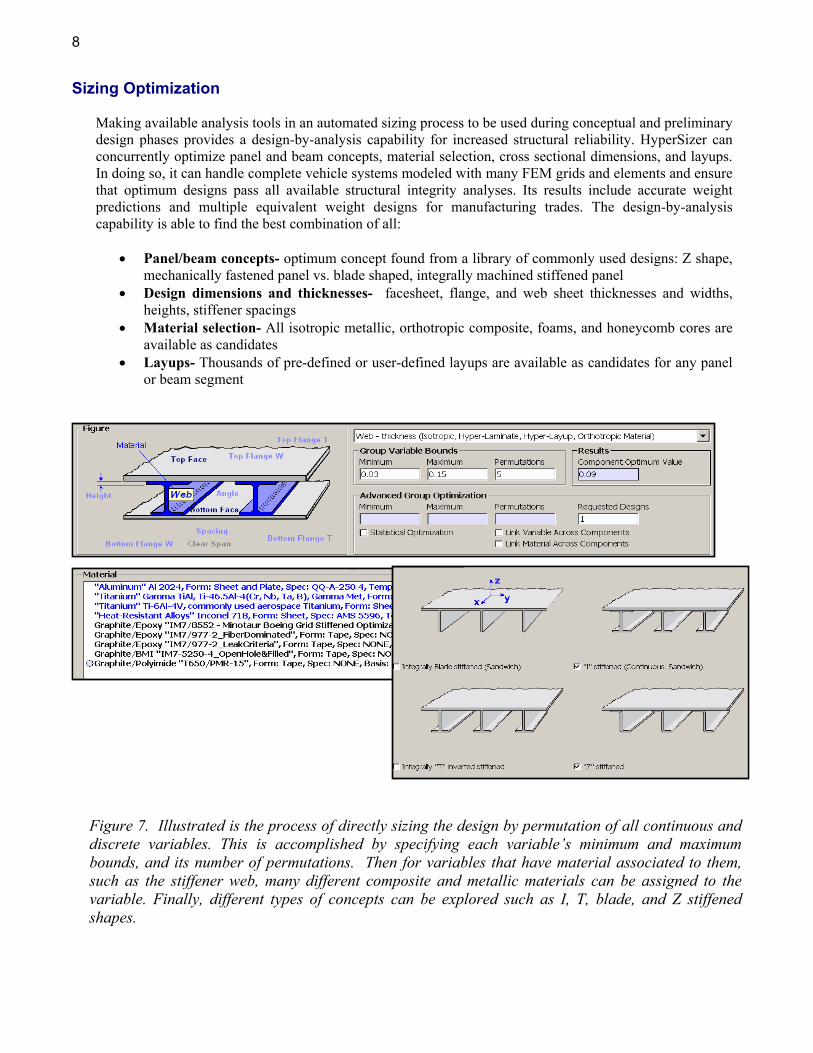
Sizing Optimization
Making available analysis tools in an automated sizing process to be used during conceptual and preliminary design phases provides a design-by-analysis capability for increased structural reliability. HyperSizer can concurrently optimize panel and beam concepts, material selection, cross sectional dimensions, and layups. In doing so, it can handle complete vehicle systems modeled with many FEM grids and elements and ensure that optimum designs pass all available structural integrity analyses. Its results include accurate weight predictions and multiple equivalent weight designs for manufacturing trades. The design-by-analysis capability is able to find the best combination of all:
• Panel/beam concepts- optimum concept found from a library of commonly used designs: Z shape, mechanically fastened panel vs. blade shaped, integrally machined stiffened panel
• Design dimensions and thicknesses- facesheet, flange, and web sheet thicknesses and widths, heights, stiffener spacings
• Material selection- All isotropic metallic, orthotropic composite, foams, and honeycomb cores are available as candidates
• Layups- Thousands of pre-defined or user-defined layups are available as candidates for any panel or beam segment
Figure 7. Illustrated is the process of directly sizing the design by permutation of all continuous and discrete variables. This is accomplished by specifying each variable’s minimum and maximum bounds, and its number of permutations. Then for variables that have material associated to them, such as the stiffener web, many different composite and metallic materials can be assigned to the variable. Finally, different types of concepts can be explored such as I, T, blade, and Z stiffened shapes.
9
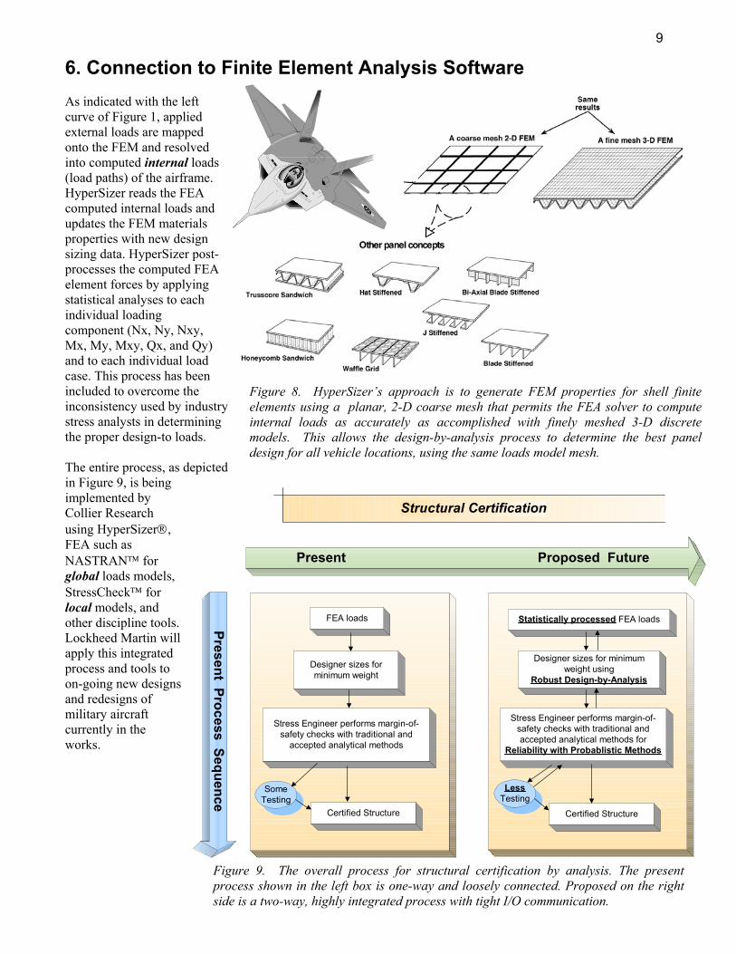
6. Connection to Finite Element Analysis Software As indicated with the left curve of Figure 1, applied external loads are mapped onto the FEM and resolved into computed internal loads (load paths) of the airframe. HyperSizer reads the FEA computed internal loads and updates the FEM materials properties with new design sizing data. HyperSizer post-processes the computed FEA element forces by applying statistical analyses to each individual loading component (Nx, Ny, Nxy, Mx, My, Mxy, Qx, and Qy) and to each individual load case. This process has been included to overcome the inconsistency used by industry stress analysts in determining the proper design-to loads. The entire process, as depicted in Figure 9, is being implemented by Collier Research using HyperSizer, FEA such as NASTRAN for global loads models, StressCheck for local models, and other discipline tools. Lockheed Martin will apply this integrated process and tools to on-going new designs and redesigns of military aircraft currently in the works.
Structural Certification
Present Proposed Future
FEA loads
Certified Structure
Designer sizes forminimum weight
Stress Engineer performs margin-of-safety checks with traditional and
accepted analytical methods
SomeTesting
Present Process Sequence
Statistically processed FEA loads
Certified Structure
Designer sizes for minimumweight using
Robust Design-by-Analysis
Stress Engineer performs margin-of-safety checks with traditional andaccepted analytical methods for
Reliability with Probablistic Methods
LessTesting
Determine best panel concept and material selections for all vehicle internal and external surface areas
Figure 9. The overall process for structural certification by analysis. The present process shown in the left box is one-way and loosely connected. Proposed on the right side is a two-way, highly integrated process with tight I/O communication.
Figure 8. HyperSizer’s approach is to generate FEM properties for shell finite elements using a planar, 2-D coarse mesh that permits the FEA solver to compute internal loads as accurately as accomplished with finely meshed 3-D discrete models. This allows the design-by-analysis process to determine the best panel design for all vehicle locations, using the same loads model mesh.
10
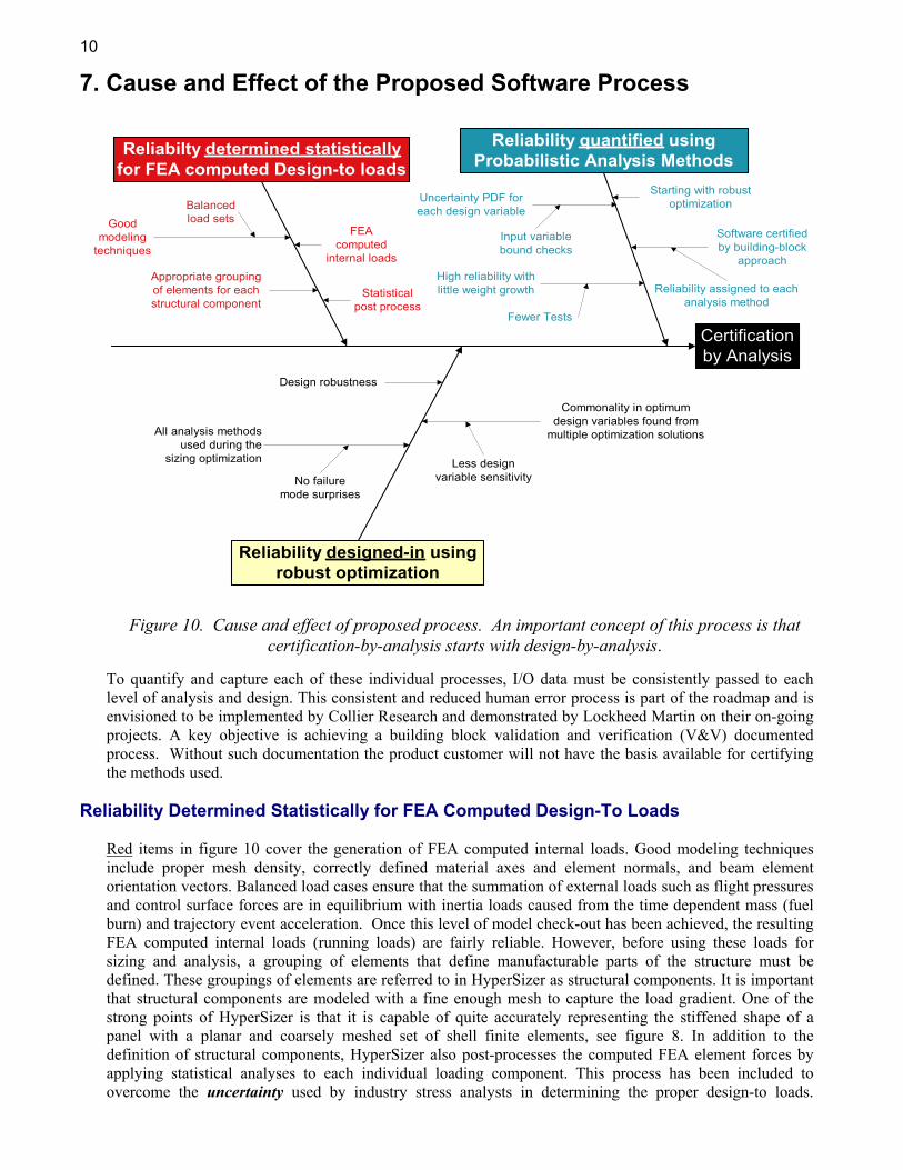
7. Cause and Effect of the Proposed Software Process
To quantify and capture each of these individual processes, I/O data must be consistently passed to each level of analysis and design. This consistent and reduced human error process is part of the roadmap and is envisioned to be implemented by Collier Research and demonstrated by Lockheed Martin on their on-going projects. A key objective is achieving a building block validation and verification (V&V) documented process. Without such documentation the product customer will not have the basis available for certifying the methods used.
Reliability Determined Statistically for FEA Computed Design-To Loads Red items in figure 10 cover the generation of FEA computed internal loads. Good modeling techniques include proper mesh density, correctly defined material axes and element normals, and beam element orientation vectors. Balanced load cases ensure that the summation of external loads such as flight pressures and control surface forces are in equilibrium with inertia loads caused from the time dependent mass (fuel burn) and trajectory event acceleration. Once this level of model check-out has been achieved, the resulting FEA computed internal loads (running loads) are fairly reliable. However, before using these loads for sizing and analysis, a grouping of elements that define manufacturable parts of the structure must be defined. These groupings of elements are referred to in HyperSizer as structural components. It is important that structural components are modeled with a fine enough mesh to capture the load gradient. One of the strong points of HyperSizer is that it is capable of quite accurately representing the stiffened shape of a panel with a planar and coarsely meshed set of shell finite elements, see figure 8. In addition to the definition of structural components, HyperSizer also post-processes the computed FEA element forces by applying statistical analyses to each individual loading component. This process has been included to overcome the uncertainty used by industry stress analysts in determining the proper design-to loads.
Figure 10. Cause and effect of proposed process. An important concept of this process is that certification-by-analysis starts with design-by-analysis.
Certificationby Analysis
Reliability quantified usingProbabilistic Analysis Methods
Reliability designed-in usingrobust optimization
Reliabilty determined statisticallyfor FEA computed Design-to loads
Goodmodeling
techniques
Balancedload sets
Appropriate groupingof elements for eachstructural component
Uncertainty PDF foreach design variable
Input variablebound checks
High reliability withlittle weight growth
Fewer Tests
Reliability assigned to eachanalysis method
Design robustness
All analysis methodsused during the
sizing optimization
No failuremode surprises
Commonality in optimumdesign variables found from
multiple optimization solutions
Less designvariable sensitivity
FEAcomputed
internal loads
Statisticalpost process
Software certifiedby building-block
approach
Starting with robustoptimization
11
HyperSizer provides a more reliable way to establish the proper magnitude of forces, and attempts to account for possible FEA solution non-convergence due to a lack of mesh refinement.
Reliability designed-in using robust optimization
Yellow items in figure 10 cover sizing optimization of the structure. A primary concept of this proposed process is to use nearly all of the available analyses during sizing optimization so that no new failure mode surprises will occur when going to the final analysis step. Another primary concept for achieving a reliable and robust optimization is that design variable sensitivities are minimized and a commonality in optimum design variables is found from multiple optimized solutions. HyperSizer accomplishes this by performing a statistical optimization on the found optimum designs. Since multiple, equally performing optimum designs are found, if one particular design is later discovered to have difficulty in certification, alternate fall back designs are readily available and can easily be substituted. The ultimate objective is to find a robust design to manufacture and certify.
Reliability Quantified Using Probabilistic Methods
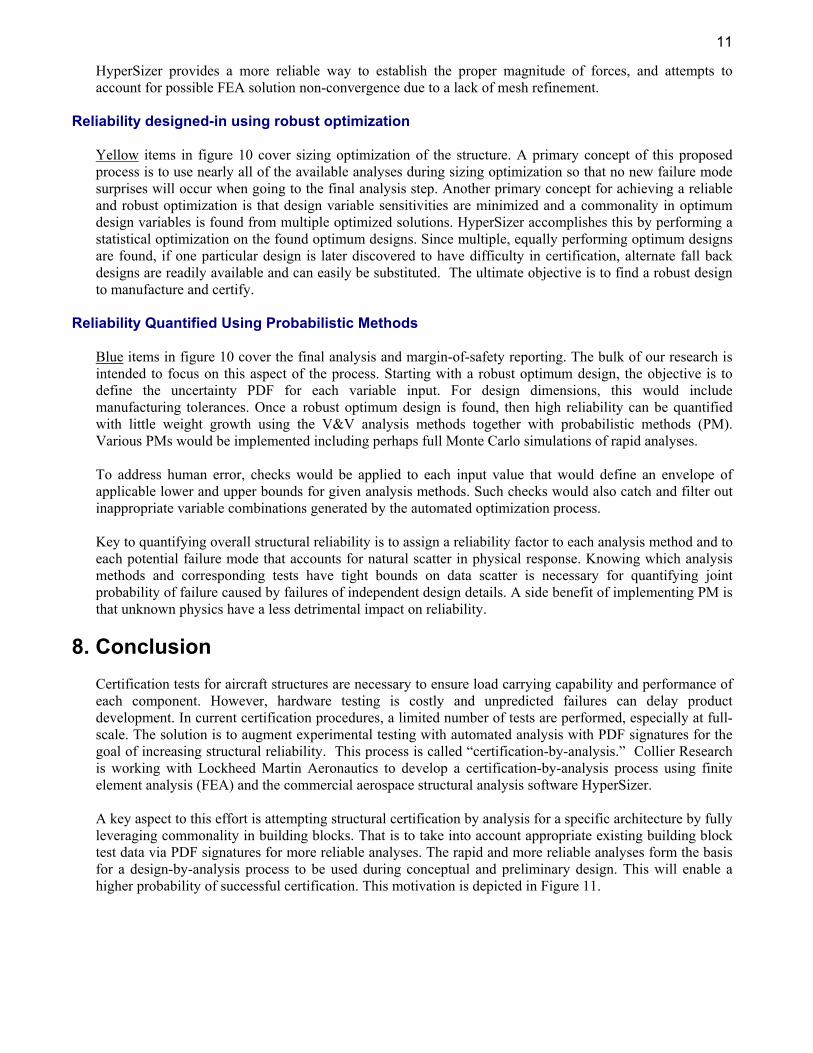
Blue items in figure 10 cover the final analysis and margin-of-safety reporting. The bulk of our research is intended to focus on this aspect of the process. Starting with a robust optimum design, the objective is to define the uncertainty PDF for each variable input. For design dimensions, this would include manufacturing tolerances. Once a robust optimum design is found, then high reliability can be quantified with little weight growth using the V&V analysis methods together with probabilistic methods (PM). Various PMs would be implemented including perhaps full Monte Carlo simulations of rapid analyses. To address human error, checks would be applied to each input value that would define an envelope of applicable lower and upper bounds for given analysis methods. Such checks would also catch and filter out inappropriate variable combinations generated by the automated optimization process. Key to quantifying overall structural reliability is to assign a reliability factor to each analysis method and to each potential failure mode that accounts for natural scatter in physical response. Knowing which analysis methods and corresponding tests have tight bounds on data scatter is necessary for quantifying joint probability of failure caused by failures of independent design details. A side benefit of implementing PM is that unknown physics have a less detrimental impact on reliability.
8. Conclusion
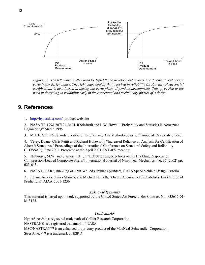
Certification tests for aircraft structures are necessary to ensure load carrying capability and performance of each component. However, hardware testing is costly and unpredicted failures can delay product development. In current certification procedures, a limited number of tests are performed, especially at full-scale. The solution is to augment experimental testing with automated analysis with PDF signatures for the goal of increasing structural reliability. This process is called “certification-by-analysis.” Collier Research is working with Lockheed Martin Aeronautics to develop a certification-by-analysis process using finite element analysis (FEA) and the commercial aerospace structural analysis software HyperSizer. A key aspect to this effort is attempting structural certification by analysis for a specific architecture by fully leveraging commonality in building blocks. That is to take into account appropriate existing building block test data via PDF signatures for more reliable analyses. The rapid and more reliable analyses form the basis for a design-by-analysis process to be used during conceptual and preliminary design. This will enable a higher probability of successful certification. This motivation is depicted in Figure 11.
12
9. References
1. http://hypersizer.com/, product web site
2. NASA TP-1998-207194, M.H. Rheinfurth and L.W. Howell “Probability and Statistics in Aerospace Engineering” March 1998
3. MIL HDBK 17e, Standardization of Engineering Data Methodologies for Composite Materials”, 1996.
4. Veley, Duane, Chris Pettit and Richard Holzwarth, "Increased Reliance on Analysis for Certification of Aircraft Structures," Proceedings of the International Conference on Structural Safety and Reliability (ICOSSAR), June 2001. Presented at the April 2001 AVT-092 meeting
5. Hilburger, M.W. and Starnes, J.H., Jr. “Effects of Imperfections on the Buckling Response of Compression-Loaded Composite Shells”, International Journal of Non-linear Mechanics, No. 37 (2002) pp. 623-643.
6 . NASA SP-8007, Buckling of Thin-Walled Circular Cylinders, NASA Space Vehicle Design Criteria
7 . Johann Arbocz, James Starnes, and Michael Nemeth, “On the Accuracy of Probabilistic Buckling Load Predictions” AIAA-2001-1236
Acknowledgements This material is based upon work supported by the United States Air Force under Contract No. F33615-01-M-3125.
Trademarks HyperSizer® is a registered trademark of Collier Research Corporation NASTRAN® is a registered trademark of NASA MSC/NASTRAN™ is an enhanced proprietary product of the MacNeal-Schwendler Corporation. StressCheck™ is a trademark of ESRD
CostCommitment $
Design Phase in TimePD
ProductDevelopment
80%
Locked InReliability
(Probabilityof successfulcertification)
Design Phase in TimePD
ProductDevelopment
Figure 11. The left chart is often used to depict that a development project’s cost commitment occurs early in the design phase. The right chart depicts that a locked in reliability (probability of successful certification) is also locked in during the early phase of product development. This gives rise to the need in designing-in reliability early in the conceptual and preliminary phases of a design.