POWER TOOLS GENERAL CATALOG - ATA Tools
100
POWER TOOLS GENERAL CATALOG URYU POWER TOOLS GENERAL CATALOG
-
Upload
khangminh22 -
Category
Documents
-
view
0 -
download
0
Transcript of POWER TOOLS GENERAL CATALOG - ATA Tools

URYUPowerTools
www.uryu.co.jp
POWER TOOLS GENERAL CATALOG
UR
YU
POW
ER TOOLS GENERAL CATALOG
POWER TOOLS GENERAL CATALOGBOLT & NUT SETTERS / SCREWDRIVERS / ABRASIVE TOOLS / DRILLS & TAPPERS / PERCUSSION TOOLS / TESTERS & ACCESSORIES
www.uryu.co.jp
19-04
Specifications & contents are subject to change without notice.
DISTRIBUTED BY :
P.O. Box 7 Higashinari, Osaka, Japan.Telephone No : 816-6973-9414~9415Fax : 816-6972-0346E-Mail : [email protected] : //www.uryu.co.jp
Printed in Japan(DAI-19-04-1522)

UH-10
U-900USP
USG-181C
S-1-3
B-100
P-20
F-1N
UW-125S
UW-60E
URD-23R
URD-32HR
UW-38
HO-1
U-100R
We hope to introduce products which are satisfied in every operation scenes in customers stand.
This is in our initial origin and our future subject.
We will keep progress with strong spirit of investigation and
dedicate to society with best products meeting social confidence from now on.
100 years for is history of “Challenges” pursuing innovative tools.

BP-T40D UDP-A60MC
UA50MC
UA70SMC
UAT50SL
UA700AMCUAT80
UDT-25
Towards the next innovation.
UAN-F130-025
UA70SMC
UFT-10
UEC-4800TP(SD) UEC-4800(SD) UTM-1500
100 years for is history of “Challenges” pursuing innovative tools.
UDP-TA50D(B)
UECP-4800
UDBP-A50(P)
1POWER TOOLS gENERAL CATALOg

PIONEER of PNEUMATICTOOLS in JAPAN
established in 1915
Since established in 1915 as the pioneer manufacturer of pneumatic tools in Japan, we have been maintaining the top leading position in all respects. Now, the name of
"URYU" has become remarkably popular worldwide with the customers who love quality. It is our honor to introduce our latest products to you with this catalog for
your additional productivity and greater profit.
URYU has acquired ISO14001 and ISO9001 certifications.
2 POWER TOOLS gENERAL CATALOg

CONTENTS
BOLT & NUT SETTERS 5
URYU AUTO-RELIEF FUNCTION(PAT.) 6SELECTION CHART 8
BATTERY OIL-PULSE TOOLS 12
ELECTRIC OIL-PULSE TOOLS 15
SUPER "INTELEC" SYSTEM SERIES 17
OIL-PULSE TOOLS
UAT SERIES 28UL SERIES 30CORNER TYPE 31U / UX / UXR SERIES 32
RATCHET WRENCHES 33
OPEN-END / GEARED WRENCHES 34
ANGLE NUTRUNNERS 35
IMPACT WRENCHES 36
SELECTION CHART 37
FASTENING COUNTER WITH POKA-YOKE 42
NUTRUNNERS 44
SCREWDRIVERS 45
SELECTION CHART 47TORQUE CONTROL 48CUSHION CLUTCH / IMPACT / OTHERS 50
ABRASIVE TOOLS 54
GRINDERS 55
SANDERS / POLISHERS 60
DRILLS & TAPPERS 63
DRILLS 64
TAPPERS 66
PERCUSSION TOOLS 67
RIVETING HAMMERS 68
IMPACT CUTTERS / FLUX CHIPPERS 70
CHIPPING HAMMERS 71
TESTERS & ACCESSORIES 73
TESTERS 74
ACCESSORIES 78
SAFETY MANUAL 79
NOISE & VIBRATION 82
INDEX / URYU NETWORK 96
3POWER TOOLS gENERAL CATALOg
BOLT & NUT SETTERSSCREW
DRIVERSABRASIVE TOOLS
DRILLS & TAPPERSPERCUSSION TOOLS
NOISE & VIBRATIONTESTERS & ACCESSORIES

Explanation of each item in Specifications
It shows the torque for a type of tool measured by a tester and the like. The value is a measured torque in accordance with our measuring standard, which is not always identical to a break-away torque value. For a torque-adjustable model, torques with low & upper-limit are indicated respectively for the specified air pressure.
It shows the standard free speed when a tool is run under free-load. Be aware that some difference from the actual measured value may be seen since there is a permissible range with standard for free speed, for each model. For grinder, the maximum free speed is indicated. For the maximum horse power for air motor incorporated in a tool, it is generally obtained at speed around 1/2 of its free speed. For selection of drill, please take note of this point. (Refer to P. 65.)
It shows the maximum length from the tip to the end of a tool. A small variation may be seen on an actual tool due to adjustment during the assembly process. Any attachment such as socket, bit, grinding wheel, auger, snap, coupler for air supply is not included. Suspension Ring is not included, either.
It shows the weight of a tool. A small variation may be seen on an actual tool due to adjustment during the assembly process. Any attachment such as socket, bit, grinding wheel, auger, snap, coupler for air supply is not included.
It shows the distance from the center of rotation spindle (output spindle) to the maximum outside diameter. For pistol-type model, Handle (grip part) nor a projection for Suspension Ring is not included. For straight-type model, Valve Lever is not included.
It shows the shape and dimension of an output spindle. For oil-pulse wrench or impact wrench, the anvil is square drive type, and the dimension represents the distance between two surfaces. (ex. 9.5Sq = square with 9.5mm, 25.4Sq = square with 25.4mm) A model name suffixing D is for hex. bit inserting type, and the bit inserting dimension is indicated. (ex. 6.35Hex = bit attaching spindle with 6.35mm)
It shows the appropriate inside diameter of an air hose for air supply. Please be noted that the provided capacity may not be achieved if any other air hose besides the recommended inside diameter is used.
It shows air volume to be consumed by the tool. It indicates the value when the air is returned to free atmosphere pressure. Therefore, the average air consumption is approx. 1/6 of listed value when the supplied air pressure is 0.5MPa.
It shows our computer code for each model.
It shows the fastening ability for stall type which stops the motor with maximum load. It may differ from the breakaway torque of bolt fastened by each tool.
It shows the available width across flats on each ratchet wrench. Please specify Hex. size when ordering, since the hexagon socket for fastening is incorporated in these models.
It shows the available width across flats on each open-end wrench and geared wrench. Please specify Hex. size when ordering, since the hexagon socket for fastening is incorporated in these models.
It shows the inserting size of bit. Please refer to page 46 for suitable bit of each model.
It shows the available wheel dimensions for straight grinder, angle grinder, and vertical grinder. Please use within prescribed wheel dimension, since the greatest wheel dimension is decided due to safety regulations.
It shows the diameter of suitable pad/paper.
It shows the maximum diameter of drill which drill chuck mounted as standard can fix.
A tool type together with numerals represents the model name. For query or order, please specify this Model.
Model1 Air Hose Size10
Average Air Consumption11
Code12
Max. Torque13
Hex. size of Ratchet14
Hex. size of Gear socket15
Hex. Size of Bit16
Capacity (Wheel Size)17
Capacity (Pad/Paper Size)18
Drilling Capacity19
For tool selection when a required torque is vague or not clearly specified, choose an appropriate model by referring to capacity. For the optimal torque by equation for each size of bolt, please refer to P. 36. When a required torque is specified, please refer to the next item, Torque Range.
Capacity (Nominal Bolt Size)2
Torque Range3
Free Speed4
Overall Length5
Weight6
From Center to Outside7
Sq. Drive or Hex. Size8
Is shows the nominal air inlet size for a pipe screw. In principle, the tool side has got a female screw.
Air Inlet Thread (Pipe Tap)9
Model
Capacity(Nominal Bolt Size)
Torque Range Free Speedrpm
Overall Length Weight From Center
to OutsideSq. Drive or Hex. Size
Air Inlet Thread
(Pipe Tap)Air Hose Size Average Air
Consumption Code
mm in Nm ft-lbs 0.4MPa 0.5MPa 0.6MPa mm in kg lb mm in mm in in mm in m3/min ft3/min
Max. Torque Hex. size of Ratchet Hex. size of Gear socket Hex. Size of Bit Capacity (Wheel Size) Capacity (Pad/Paper Size) Drilling Capacity
Nm ft-lbs mm in mm in mm in mm in mm in mm in
21 3 4 5 6 7 8 9 10 11 12
16 17 1813 14 15 19
4 POWER TOOLS gENERAL CATALOg

BATTERY OIL-PULSE TOOLS
ELECTRIC OIL-PULSE TOOLS
SUPER " INTELEC" SYSTEM CONTROLLER
SUPER "INTELEC" SYSTEM ELECTRIC OIL-PULSE TOOLS
SUPER " INTELEC" SYSTEM AMC・MC TOOLS
UAT・ULT・UL SERIES OIL-PULSE TOOLS
U・UX・UXR SERIES OIL-PULSE TOOLS
BOLT & NUTSETTERS
RATCHET WRENCHES
OPEN-END WRENCHES・gEARED WRENCHES
ANgLE NUTRUNNERS
IMPACT WRENCHES
FASTENINg COUNTER WITH POKA-YOKE
NUTRUNNERS
5POWER TOOLS gENERAL CATALOg

URYU independent new technology “Auto Relief Function”(PAT.)
Relief Valve changes the area of bypass which plays its roles in transferring the oil pressure generated in pulse unit from high pressured area to low pressured area and adjusts the torque and number of blows depending on the target torque.However, the area of bypass in the existing relief valve system is decided at a proper adjustment position of final target torque, thus it was not possible to change the area of bypass while fastening. Newly developed “Auto Relief Function” changes the area of bypass depending on the process of fastening, which the existing relief valve does not. This new function offers you more ideal fastening than the conventional relief valve.*As auto-relief is fully opened when the bolt seats, torque spike is inhibited.
Fully opened relief valve when pulsing.
Also, make the final target torque adjustment with Relief Valve as heretofore
①Torque Spike InhibitedAs auto-relief is fully opened when the bolt seats, torque spike is inhibited.
②Decreasing Energy LossHeat generation of pulse unit is inhibited. Oil pressure to sealing part of anvil is reduced.
③ Improvement of Torque AccuracyBy reaching the stability range faster, the range of small variation can be used in fastening time of real operation. Therefore, the torque accuracy will be stable.
Driving Blade
Spring
Liner CasingOilAnvilLinerDriving BladeSpring
Rotational Direction
During Pulsing
Just before Pulsing
After PulsingOpen①
②
③
④
⑤
Just after Pulsing
Start(180°rotation from Pulsing)
Enlarged Auto Relief
High Pressure Closed
Mechanism(Patented)Patent No. 4383485
Torque
Time
Torque
Time
■Conventional Relief ValveDimension of Bypass (fixed)
②Decreasing Energy Loss
①Torque Spike inhibited
③Improvement of Torque Accuracy
■Auto-reliefDimension of Bypass (changing)
(Large) (Small)
6 POWER TOOLS gENERAL CATALOg
BOLT
& N
UT S
ETTE
RS

Oil-Pulse Unit
Torque Sensor
Angle Sensor
Magnetostrictive TransducerURYU’s brushless Magnetostrictive Torque Transducer consists of Anvil and a pair of sensor coils. Without contacting to the Anvil, the sensor coil detects load given to the Anvil (non-contact). The grooves in the anvil are provided at 45 degree angle in one region. When torque is applied to the Anvil, tensile stress appears on the region and magnet permeability increase. These permeability changes are detected, respectively transformed to the voltage change(proportional to applied torque) and converted to torque signal to control the tool.
Angle SensorAngle measurement is materialized by the resolver incorporated. The high reliability copes well with various factors such as vibrations and ambient temperature changes.
Air MotorFor lower torque ranges of types(UAT30D~UAT50 Series, UA40MC~UA60MC, UA-SMC Series and UA400AMC~UA600AMC), we newly developed the Triple-Chamber pneumatic type motor for medium speed but high output power. The Triple-Chamber motor makes it possible to maintain the low rotation speed, keeping the same motor output power from the conventional Dural-Chamber pneumatic motor in order to inhibit torque spikes caused by inertia from rotation speed of motor.
Oil-Pulse Unit
Sensor Shaft
Sensing & Exciting Coil
Magnetostrictive Transducer
Dual-Chamber Motor(Conventional)
Triple-Chamber Motor (Newly Developed)
➡High Output
Medium Speed
7POWER TOOLS gENERAL CATALOg
BOLT & NUT SETTERS
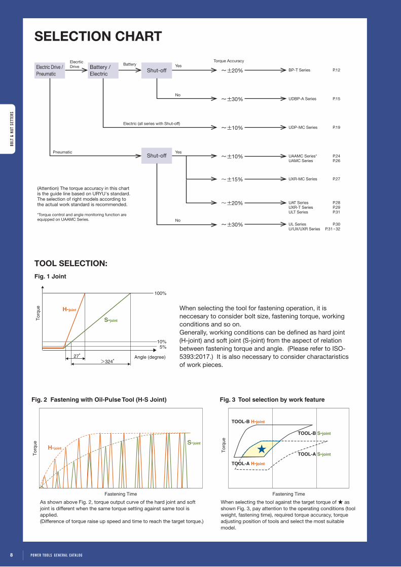
TOOL SELECTION:
Electric Drive / Pneumatic
Battery / Electric
Shut-off
Shut-off
SELECTION CHART
BP-T Series P.12
UDBP-A Series P.15
UDP-MC Series P.19
UAAMC Series* P.24UAMC Series P.26
UXR-MC Series P.27
UAT Series P.28UXR-T Series P.29ULT Series P.31
UL Series P.30U/UX/UXR Series P.31・32
ElecrticDrive Battery
Electric (all series with Shut-off)
Yes
Yes
No
No
Pneumatic
(Attention) The torque accuracy in this chart is the guide line based on URYU's standard. The selection of right models according to the actual work standard is recommended.
*Torque control and angle monitoring function are equipped on UAAMC Series.
~±20%
~±30%
~±10%
~±10%
~±15%
~±20%
~±30%
As shown above Fig. 2, torque output curve of the hard joint and soft joint is different when the same torque setting against same tool is applied. (Difference of torque raise up speed and time to reach the target torque.)
When selecting the tool against the target torque of ★ as shown Fig. 3, pay attention to the operating conditions (tool weight, fastening time), required torque accuracy, torque adjusting position of tools and select the most suitable model.
27°>324°
100%
10%5%
Angle (degree)
Tor
que
S-joint
H-joint
Tor
que S-joint
Fastening Time
H-joint
Fig. 1 Joint
Fig. 2 Fastening with Oil-Pulse Tool (H-S Joint)
Tor
que
Fastening Time
TOOL-B H-joint
TOOL-B S-joint
TOOL-A H-joint
TOOL-A S-joint
Fig. 3 Tool selection by work feature
When selecting the tool for fastening operation, it is neccesary to consider bolt size, fastening torque, working conditions and so on. Generally, working conditions can be defined as hard joint (H-joint) and soft joint (S-joint) from the aspect of relation between fastening torque and angle. (Please refer to ISO-5393:2017.) It is also necessary to consider charactaristics of work pieces.
Torque Accuracy
BOLT
& N
UT S
ETTE
RS
8 POWER TOOLS gENERAL CATALOg
BOLT
& N
UT S
ETTE
RS

TORQUE CHART FOR OIL-PULSE WRENCHESBOLT & NuT SeTTeRS
Pistol Type
20 30 40 50 100 200 400 500300 10002 3 4 5 10 60 70 80 90 600 700 800 9006 7 8 9Torque【Nm】
UDP-A700MC/(TL)
UDP-A600LMC/(TL)
●UDP-MC SERIES(P.19)
ELECTRIC TOOL ( TRANSDUCERIZED TYPE )
UDP-A100MC/(TL)
BATTERY TOOL
20 30 40 50 100 200 400 500300 10002 3 4 5 10 60 70 80 90 600 700 800 9006 7 8 9Torque【Nm】
UDBP-TA70(P), TA70(TK-P)
UDBP-A60(P)
BP-T60, T60(RF8, Z, TK), T60D, T60D(RF8, Z, TK)
UDBP-A50
BP-T50D, T50D(RF8, Z, TK)
UDBP-A50(P)
BP-T50, T50(RF8, Z, TK)
UDBP-A60
●BP-T / UDBP SERIES(P.12~15)
UDP-A120MC/(TL)
BP-T40, T40(RF8, Z, TK), T40D, T40D(RF8, Z, TK)
9POWER TOOLS gENERAL CATALOg
BOLT & NUT SETTERS

BOLT & NuT SeTTeRS
TORQUE CHART FOR OIL-PULSE WRENCHES
●UXR-T SERIES(P.29)
20 30 40 50 100 200 400 500300 10002 3 4 5 10 60 70 80 90 600 700 800 9006 7 8 9Torque【Nm】
UXR-T2400SUXR-T3000S
20 30 40 50 100 200 400 500300 10002 3 4 5 10 60 70 80 90 600 700 800 9006 7 8 9Torque【Nm】
UA500AMC
UA900AMCUA1000AMC
UA400AMC
UA700AMCUA800AMC
UA600AMC
UA1300AMC
●UAAMC SERIES(P.24, 25)
AIR TOOL ( TRANSDUCERIZED TYPE )
20 30 40 50 100 200 400 500300 10002 3 4 5 10 60 70 80 90 600 700 800 9006 7 8 9Torque【Nm】
UXR-1820MCUXR-2000MC
UXR-2400SMC
●UXR-MC SERIES(P.27)
AIR TOOL ( SHUT-OFF TYPE )●UAT SERIES(P.28, 29)
20 30 40 50 100 200 400 500300 10002 3 4 5 10 60 70 80 90 600 700 800 9006 7 8 9Torque【Nm】
UAT40 UAT40D UAT40S UAT40SDUAT30D UAT30SD
UAT50 UAT50L UAT50D UAT50DL UAT50S UAT50SL UAT50SD UAT50SDL
UAT60 UAT60D UAT60S UAT60SD
UAT70UAT70S
UAT70LUAT70SL
UAT80UAT80L
UAT90UAT90L
UAT100UAT130L
UAT200L
UAT130
UAT200
UAT100L
UAT60L UAT60DL UAT60SL UAT60SDL
UAT150
UAT150L
UAT180
UAT180L
●UAMC SERIES(P.26, 27)
20 30 40 50 100 200 400 500300 10002 3 4 5 10 60 70 80 90 600 700 800 9006 7 8 9Torque【Nm】
UA90MC
UA50MCUA50DMC
UA60SDMC
UA100MC
UA40SDMC
UA70MCUA70SMC
UA40MCUA40DMC
UA40SMCUA50SDMC
UA50SMC
UA80MC
UA60MCUA60SMC
UA130MCUA150MC
1 0 POWER TOOLS gENERAL CATALOg
BOLT
& N
UT S
ETTE
RS

BOLT & NuT SeTTeRS
Angle TypeStraight TypePistol Type Right Angle TypeTORQUE CHART FOR OIL-PULSE WRENCHES
●U / UX / UXR SERIES(P.31, 32)
20 30 40 50 100 200 400 500300 10002 3 4 5 10 60 70 80 90 600 700 800 9006 7 8 9Torque【Nm】
U-310SDU-350D U-350SD
UX-900S
UX-1000S
UX-500CUX-612C UX-612A
UX-700CUX-800C
UX-ST800 UX-900C
UX-1000C
UXR-1820UXR-2000 UXR-2000S
UXR-2400SUXR-3000S
UX-ST1000
●UL SERIES(P.30)
20 30 40 50 100 200 400 500300 10002 3 4 5 10 60 70 80 90 600 700 800 9006 7 8 9Torque【Nm】
UL60 UL60S
UL40 UL40SUL40D UL40SD
UL50D UL50SDUL50 UL50S UL60D UL60SD
UL30 UL30S UL30D UL30SD
UL70
UL150
UL70SUL80
UL130
UL90UL100
AIR TOOL ( NON SHUT-OFF TYPE )
AIR TOOL ( SHUT-OFF TYPE )
20 30 40 50 100 200 400 500300 10002 3 4 5 10 60 70 80 90 600 700 800 9006 7 8 9Torque【Nm】
ULT60C ULT60CLULT50C ULT50CL
ULT70CH ULT70CHLULT70C ULT70CL
ULT40C
●ULT SERIES(P.31)
UX-1300S
11POWER TOOLS gENERAL CATALOg
BOLT & NUT SETTERS

BATTERY DRIVE
Evolving Battery Oil Pulse Tool BP-T series
BP-T SERIES [ SHUT-OFF TYPE ]
BATTeRY OIL-PuLSe TOOLS
• New grip style in terms of operator’s comfort. It protects operator from fatigue.
• Independent cooling fan reduces heat of pulse unit contributing to comfortable operation.
• Compact & High-capacity Li-ion battery provides more fasteners per charge.
FEATURES
The model name suffixing (D) is the Quick-change driver anvil type.
On pulling the sleeve, insert or take off the bit.
6.35mm
9mm
Quick-change driver anvil type
Specifications (Shut-off Type)
Model
Capacity(Nominal Bolt Size) Torque Range
FreeSpeed
(Approx.)
Overall Lengthless
Socket or Bit(Approx.)
Weightless
Socket or Bit
From Centerto Outside(Approx.)
Sq. Driveor
Hex. Size Battery Voltage
(Capacity)Code
mm in Nm ft-lbs rpm mm inwith battery with no battery
mm in mm inkg lb kg lb
BP-T40D 5 No. 10 4.5-8 3.3-5.9 3300 200 7 7/8 1.4 3.08 1.15 2.53 27 1 1/16 6.35 Hex. 1/4 Hex. 10.8V (2.0Ah) 10A02
BP-T50D 6-8 1/4-5/16 6.5-13 4.8-9.6 3900 200 7 7/8 1.4 3.08 1.15 2.53 27 1 1/16 6.35 Hex. 1/4 Hex. 10.8V (2.0Ah) 10C02
BP-T60D 8 5/16 13-26 9.6-19.2 4800 205 8 5/64 1.6 3.52 1.25 2.75 27 1 1/16 6.35 Hex. 1/4 Hex. 14.4V (2.0Ah) 10e02
BP-T40 5 No. 10 4.5-8 3.3-5.9 3300 197 7 4/3 1.4 3.08 1.15 2.53 27 1 1/16 9.5 sq. 3/8 sq. 10.8V (2.0Ah) 10A12
BP-T50 6-8 1/4-5/16 7-15 5.1-11.1 3900 197 7 4/3 1.4 3.08 1.15 2.53 27 1 1/16 9.5 sq. 3/8 sq. 10.8V (2.0Ah) 10C12
BP-T60 8 5/16 13-26 9.6-19.2 4800 202 7 61/64 1.6 3.52 1.25 2.75 27 1 1/16 9.5 sq. 3/8 sq. 14.4V (2.0Ah) 10e12
*Torque Range is a guideline value. Please make tool selection appropriately in accordance with an actual application. *Battery or Battery Charger is not included. Please use corresponding models of Panasonic.
BP-T50D BP-T60BP-T60D
Protector
OPTION
Optional Tool Jackets Size Part Number used for
S10C-840-110C-840-410D-840-2
BP-T40(D), BP-T50(D)BP-T40(D)(RF8)/(TK), BP-T50(D)(RF8)/(TK) BP-T40(D)(Z), BP-T50(D)(Z)
M10e-840-110e-840-410F-840-2
BP-T60(D)BP-T60(D)(RF8)/(TK)BP-T60(D)(Z)
S
M
BP-T40D
1 2 POWER TOOLS gENERAL CATALOg
BOLT
& N
UT S
ETTE
RS

BATTERY DRIVE
DERIVATIVE MODELS OF BP-T SERIES [ SHUT-OFF TYPE ]
BATTeRY OIL-PuLSe TOOLS
*For information on the Radio Law in your country, please contact your nearest URYU distributor.
Wireless RF8 Type / Z(ZigBee) Type (*)
Specifications (Shut-off Type)
Model
Capacity(Nominal Bolt Size) Torque Range
FreeSpeed
(Approx.)
Overall Lengthless
Socket or Bit(Approx.)
Weightless
Socket or Bit
From Centerto Outside(Approx.)
Sq. Driveor
Hex. Size Battery Voltage
(Capacity)Code
mm in Nm ft-lbs rpm mm inwith battery with no battery
mm in mm inkg lb kg lb
BP-T40D(RF8) 5 No. 10 4.5-8 3.3-5.9 3300 207 8 5/32 1.4 3.08 1.15 2.53 27 1 1/16 6.35 Hex. 1/4 Hex. 10.8V (2.0Ah) 10A62
BP-T50D(RF8) 6-8 1/4-5/16 6.5-13 4.8-9.6 3900 207 8 5/32 1.4 3.08 1.15 2.53 27 1 1/16 6.35 Hex. 1/4 Hex. 10.8V (2.0Ah) 10C62
BP-T60D(RF8) 8 5/16 13-26 9.6-19.2 4800 212 8 11/32 1.6 3.52 1.25 2.75 27 1 1/16 6.35 Hex. 1/4 Hex. 14.4V (2.0Ah) 10e62
BP-T40(RF8) 5 No. 10 4.5-8 3.3-5.9 3300 204 8 1/32 1.4 3.08 1.15 2.53 27 1 1/16 9.5 sq. 3/8 sq. 10.8V (2.0Ah) 10A72
BP-T50(RF8) 6-8 1/4-5/16 7-15 5.1-11.1 3900 204 8 1/32 1.4 3.08 1.15 2.53 27 1 1/16 9.5 sq. 3/8 sq. 10.8V (2.0Ah) 10C72
BP-T60(RF8) 8 5/16 13-26 9.6-19.2 4800 209 8 15/64 1.6 3.52 1.25 2.75 27 1 1/16 9.5 sq. 3/8 sq. 14.4V (2.0Ah) 10e72
BP-T40D(Z) 5 No. 10 4.5-8 3.3-5.9 3300 218 8 37/64 1.4 3.08 1.15 2.53 27 1 1/16 6.35 Hex. 1/4 Hex. 10.8V (2.0Ah) 10B12
BP-T50D(Z) 6-8 1/4-5/16 6.5-13 4.8-9.6 3900 218 8 37/64 1.4 3.08 1.15 2.53 27 1 1/16 6.35 Hex. 1/4 Hex. 10.8V (2.0Ah) 10D12
BP-T60D(Z) 8 5/16 13-26 9.6-19.2 4800 223 8 25/32 1.6 3.52 1.25 2.75 27 1 1/16 6.35 Hex. 1/4 Hex. 14.4V (2.0Ah) 10F12
BP-T40(Z) 5 No. 10 4.5-8 3.3-5.9 3300 215 8 15/32 1.4 3.08 1.15 2.53 27 1 1/16 9.5 sq. 3/8 sq. 10.8V (2.0Ah) 10B22
BP-T50(Z) 6-8 1/4-5/16 7-15 5.1-11.1 3900 215 8 15/32 1.4 3.08 1.15 2.53 27 1 1/16 9.5 sq. 3/8 sq. 10.8V (2.0Ah) 10D22
BP-T60(Z) 8 5/16 13-26 9.6-19.2 4800 220 8 21/32 1.6 3.52 1.25 2.75 27 1 1/16 9.5 sq. 3/8 sq. 14.4V (2.0Ah) 10F22
*Torque Range is a guideline value. Please make tool selection appropriately in accordance with an actual application. *Battery or Battery Charger is not included. Please use corresponding models of Panasonic.
RF8 : Pokayoke configuration
Use UTM-1500.
TW-800R-EXP orTW-800R-EXS issubstitute.
Lighting pairing switch
Fastener counter
Power adaptor
Herutu-madereceiver
TW-800R
PowerSwitch
Transmit Receive
Transmit Receive
Z(ZigBee) : Pokayoke configuration
Receive
To UTM-1500 or PLC
Relay output exclusive cable assembly
1 3POWER TOOLS gENERAL CATALOg
BOLT & NUT SETTERS

BP-T SERIES [ SHUT-OFF TYPE ]
BATTERY DRIVE BATTeRY OIL-PuLSe TOOLS
The model name suffixing (D) is the Quick-change driver anvil type.
On pulling the sleeve, insert or take off the bit.
6.35mm
9mm
Quick-change driver anvil type
• Squeeze trigger, and shut-off information LED will light red.
• Switch off the trigger before automatic shut-off, and the LED will continue lighting red for 3 seconds and go out.
• The LED lights green with 1 pulse buzzer sounding for automatic shut-off.
(Note) Automatic shut-off by retry repairing incomplete job error will light LED by switching green and red together.
FEATURES
Incomplete Job Detection (TK) Type
LED with red lighting tells you incomplete job (premature trigger off)
BP-T60D(TK)
Specifications (Shut-off Type)
Model
Capacity(Nominal Bolt Size) Torque Range
FreeSpeed
(Approx.)
Overall Lengthless
Socket or Bit(Approx.)
Weightless
Socket or Bit
From Centerto Outside(Approx.)
Sq. Driveor
Hex. Size Battery Voltage
(Capacity)Code
mm in Nm ft-lbs rpm mm inwith battery with no battery
mm in mm inkg lb kg lb
BP-T40D(TK) 5 No. 10 4.5-8 3.3-5.9 3300 207 8 5/32 1.4 3.08 1.15 2.53 27 1 1/16 6.35 Hex. 1/4 Hex. 10.8V (2.0Ah) 10A82
BP-T50D(TK) 6-8 1/4-5/16 6.5-13 4.8-9.6 3900 207 8 5/32 1.4 3.08 1.15 2.53 27 1 1/16 6.35 Hex. 1/4 Hex. 10.8V (2.0Ah) 10C82
BP-T60D(TK) 8 5/16 13-26 9.6-19.2 4800 212 8 11/32 1.6 3.52 1.25 2.75 27 1 1/16 6.35 Hex. 1/4 Hex. 14.4V (2.0Ah) 10e82
BP-T40(TK) 5 No. 10 4.5-8 3.3-5.9 3300 204 8 1/32 1.4 3.08 1.15 2.53 27 1 1/16 9.5 sq. 3/8 sq. 10.8V (2.0Ah) 10A92
BP-T50(TK) 6-8 1/4-5/16 7-15 5.1-11.1 3900 204 8 1/32 1.4 3.08 1.15 2.53 27 1 1/16 9.5 sq. 3/8 sq. 10.8V (2.0Ah) 10C92
BP-T60(TK) 8 5/16 13-26 9.6-19.2 4800 209 8 15/64 1.6 3.52 1.25 2.75 27 1 1/16 9.5 sq. 3/8 sq. 14.4V (2.0Ah) 10e02
*Torque Range is a guideline value. Please make tool selection appropriately in accordance with an actual application. *Battery or Battery Charger is not included. Please use corresponding models of Panasonic.
1 4 POWER TOOLS gENERAL CATALOg
BOLT
& N
UT S
ETTE
RS

Specifications (Non Shut-off Type / Shut-off Type)
Model
Capacity(Nominal Bolt Size) Torque Range
FreeSpeed
(Approx.)
Overall Length lessSocket or Bit
(Approx.)
Weightless
Socket or Bit
From Centerto Outside(Approx.)
Sq. Driveor
Hex. SizeBattery Voltage
(Capacity)
Battery Model
NumberCode
mm in Nm ft-lbs rpm mm inwith battery with no battery
mm in mm inkg lb kg lb
UDBP-A50 6-8 1/4-5/16 8-17 5.9-12.6 5300 203 7 63/64 1.4 3.08 1.11 2.44 29.5 1 5/32 6.35 Hex. 1/4 Hex. 11.1V (1.5Ah) uB111Li 08022
UDBP-A50(P) 6-8 1/4-5/16 11-20 8.1-14.8 5300 200 7 7/8 1.4 3.08 1.11 2.44 29.5 1 5/32 9.5 sq. 3/8 sq. 11.1V (1.5Ah) uB111Li 08042
UDBP-A60 8-10 5/16-13/32 17-30 12.6-22.2 4800 218 8 37/64 1.7 3.74 1.25 2.75 29.5 1 5/32 6.35 Hex. 1/4 Hex. 22.2V (1.5Ah) uB222Li 08052
UDBP-A60(P) 8-10 5/16-13/32 20-32 14.8-23.7 4800 215 8 15/32 1.7 3.74 1.25 2.75 29.5 1 5/32 9.5 sq. 3/8 sq. 22.2V (1.5Ah) uB222Li 08072
UDBP-TA70(P) 8-10 5/16-13/32 26-47 19.2-34.7 4800 234 9 7/32 2.0 4.4 1.39 3.06 29.5 1 5/32 9.5 sq. 3/8 sq. 33.3V (1.5Ah) uB333Li 08392
UDBP-TA70(TK-P) 8-10 5/16-13/32 26-47 19.2-34.7 4800 234 9 7/32 2.0 4.4 1.39 3.06 29.5 1 5/32 9.5 sq. 3/8 sq. 33.3V (1.5Ah) uB333Li 07N72
(P) = Square Anvil TypeModel name suffixing “T” is shut-off type.*Torque Range is a guideline value. Please make tool selection appropriately in accordance with an actual application. *Battery or Battery Charger is not included.
The tool, charger, and 2 sets of batteries are also available as a set.
Charger
Charger Model Number uBCPower Supply AC100V - AC240V*
Power 100V: 225VAConsumption 240V: 295VA
Weight (Approx.) 1.6kgOperating
Temperature Range 5-40℃
*Use the power cable which URYU ships with the charger.
Charging Time Battery Capacity Time (Approx.)
80% 40 minutes100% 64 minutes
OPTION
Battery
Battery Model Number UB111Li UB222Li UB333Li
Voltage 11.1V 22.2V 33.3VCapacity 1.5Ah 1.5Ah 1.5Ah
Weight (Approx.) 0.29Kg 0.45Kg 0.61Kg
The lithium-ion battery is used for UDBP series.• Its longevity is not affected by repeated recharging after being only partially discharged.
• The battery power indicator provides you with a visual indication to charge the lithium-ion battery. ● = enough charge ● = low charge(recharging needed) ● = very low charge (immediate recharging needed)
• The slide design battery provides the high-energy efficiency in power.
Tightening numbers per full charge Model Torque(Nm) Tester & Bolt Size Battery Model Tightening Numbers (Approx.)
UDBP-TA40 7 uFT-6(M6) uB111Li Hard Joint 840Soft Joint 270
UDBP-TA50・A50 11 uFT-10(M8) uB111Li Hard Joint 580Soft Joint 190
UDBP-TA50(P)・A50(P) 12.5 uFT-10(M8) uB111Li Hard Joint 580Soft Joint 190
UDBP-TA60・A60 24 uFT-10(M10) uB222Li Hard Joint 500Soft Joint 170
UDBP-TA60(P)・A60(P) 26 uFT-10(M10) uB222Li Hard Joint 500Soft Joint 170
UDBP-TA70(P) 40 uFT-16(M12) uB333Li Hard Joint 600Soft Joint 210
* Torque is set at Hard Joint. Numbers of tightening per charge varies depending on torque level, fastener length and application.
ELECTRIC DRIVE
UDBP SERIES [NON SHUT-OFF TYPE / SHUT-OFF TYPE]
eLeCTRIC OIL-PuLSe TOOLS
UDBP-TA70(P)UDBP-A50(P)Non shut-off type The model name not suffixing (P) is
the Quick-change driver anvil type.
On pulling the sleeve, insert or take off the bit.
6.35mm
9mm
Quick-change driver anvil type
Identification Color [Light Blue] (A50 & A60)
1 5POWER TOOLS gENERAL CATALOg
BOLT & NUT SETTERS
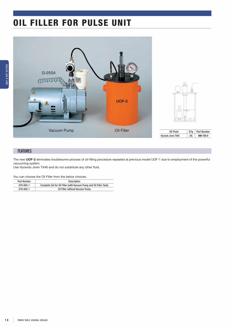
OIL FILLER FOR PULSE UNIT
The new UOF-2 eliminates troublesome process of oil-filling procedure repeated at previous model UOF-1 due to employment of the powerful vacuuming system.Use Hyrando Jinen TX46 and do not substitute any other fluid.
Vacuum Pump Oil Filler
UOF-2
G-25SA
OFF ON
Oil Fluid Q'ty Part NumberHyrando Jinen TX46 20L 998-735-0
FEATURES
Part Number Description878-945-1 Complete Set for Oil Filler (with Vacuum Pump and Oil Filler Tank)878-955-1 Oil Filler without Vacuum Pump
You can choose the Oil Filler from the below choices.
1 6 POWER TOOLS gENERAL CATALOg
BOLT
& N
UT S
ETTE
RS

� ToolController�
UDP-MCSERIES▶P.19
UAAMCSERIES▶P.24
UAMCSERIES▶P.26
UXR-MCSERIES▶P.27
UECP SERIES ▶P.18 ● — — —
UEC-4800(SD) SERIES ▶P.20 — ● ● ●
UEC-5500 ▶P.22 — — ● ●
URYU Electric control system series running with more precise control meets a scene requiring accurate and delicate control.
Oil Pulse Wrenches
Electric control systemSUPER "INTELEC" SERIES
・Transmit and receive setting values
・Receive and store fastening results
・Receive and store waveform data
・Receive and store statistical data
・I / O check
・ Programming is easy on front panel. You can also upload your program from PC. (The exclusive setup software is necessary)
・ Counting a number of fastener and various error detection functions are equipped.
・ Controller meets various work condition, maximum 8 different kinds works can be set.
・ A fastening number and a pulse number can be controlled.
・ Fastening torque result and torque waveform can be shown.
・ Standard deviations, Cp value, Cpk value can be analyzed instantly from the stored data within the controller and you can graph the statistical data.
・ Check of Input/Output and display of errors can be confirmed with beep sound and display on PC or Front panel of controller. (For touch panel type only)
When�the�power�turns�on,�self-checking�function�automatically�runs�as�ROM→RAM→A/D→Filter�Check→ZERO�CAL�Check�and�etc.
・ When the dedicated setup software is installed to PC, setting parameters can be transmitted and received between controller and PC, fastening result/waveform data can be received from controller.
・ When a controller is connected with a host computer to control an assembly line, the controller receive a fastening instruction from the host computer and return the fastening result with the instruction to host computer.
POINT
2POINT
1
POINT
3POINT
4
Function on setup software with PC.
Control a tool easily by a controller.
Self-checking function Ethernet (TCP/IP) capable
BOlT & NuT SeTTerS
1 7POWer TOOlS geNeral caTalOg

Hub
Host computer
PC/Controller
PC for setup
Sequencer (PLC)
Rear panelFront panel
Outlet
Power cable
PC cable
Joint Cable Assembly
LAN Cable
Tool
*2-Pin ConversionAdapter must be grounded.
* Joint Cable Assembly is necessary to connect tool with controllerFor UDP-A600LMC・A700MC・A100MC 910-517-0: 5M / 910-518-0: 10M / 910-519-0: 15M / 910-624-0: 20MFor UDP-A120MC 910-567-0: 5M / 910-568-0: 10M / 910-569-0: 15M / 910-625-0: 20M
UECP SERIESSUPER “INTELEC” SYSTEM CONTROLLER
The UECP series Controller becomes one unit combined driver unit to drive UDP-MC series electric oil pulse tools and multi-function controller of UEC-4810 to control a transducerized tool.
UECP-4810 UDP-A600LMC・A700MC・A100・A120 MC Series
UECP Series System Layout
UECP SERIES SPECIFICATIONSPOWER SUPPLY UECP-4810A: AC115V UECP-4810E: AC230VPOWER FREQUENCY 50 / 60 HzNOISE PROTECTION 1000V 1μS (accoding to noise simulator)INSULATION PROTECTION DC500V over 10MΩAMBIENT TEMPERATURE 0〜50℃ (non-freezing)AMBIENT HUMIDITY 90% RH or less (no dew)WEIGHT 11.30 kgDIMENSIONS 265 (D) × 222 (W) × 200 (H)
MAIN FUNCTIONS Torque control, Torque monitorFastener number count
PARAMETER SETUPManual input on front LCD panel
By PC (with setup software)
DISPLAY
Torque resolution ±2048 (12 bit by A/D use)LCD typeLCD ( 20 letters × 4 lines )
Work number, Bolt count number, Tightening time and Pulse blow number1-digit Digital Display (DPM)Work number displayed4-digit Digital Display (DPM)
Torque reading displayed
LED
Total Lamp (for Count Judgment) : OK (green) / NOK (red)Torque Lamp (for Torque Judgment) : LOW (yellow) / OK (green) / HIGH (red)
INPUT TERMINAL SIGNALOperation Voltage/Current : DC24V / about 10mA6 terminals available (programmable) Note: Contact input necessary
OUTPUT TERMINAL SIGNAL Contact Capacity : DC30V, 1A6 terminals available (programmable), VALVE
OPTION Setting PC Cable (Straight) Part Number : 910-219-0
CODE (A/E) 81862/81872
1 8 POWer TOOlS geNeral caTalOg
BOlT
& N
uT S
eTTe
rS

• URYU’s unique non-contact Magnetostrictive transducer incorporated. (Refer to P. 7.)
• The UDP tool is driven by commercial electricity. This helps you build an assembly line easily and adjust it flexibly to the layout change.
• High Power and High efficiency adopted by IPM motor. (except for A100MC/A120MC)
• Cooling fan is activated automatically when pulling the throttle trigger, which contributes to heat reduction and increase number of fastening.
• URYU know-how acquired from the pneumatic oil-pulse tool development, and newly developed “Auto Relief Function”(PAT.) is adopted.
• The intelligence of UDP-MC tool stops operation immediately to protect the operator from the failure including overloaded operation, short circuit, and broken wire, which minimizes the possible influence over operator and shop floor.
[FUNCTIONS]• Motor speed/current is programmable.
・ Motor current can be set in 4 steps
・ Motor rotational speed can be set in 100 rpm increments(by the 2-step fastening, torque spike at bolt seating is inhibited, and make it possible to cover the wider torque range.)
• The functions of various fastening error detections and fastener number count down assure your operations.
• Makes setup or changeover of fastening torque and fastening number count.
• Tool’s maintenance is possible by counting both total cycle numbers(how many fasteners) and/or total pulse numbers.
• Input/Output check and error messages can be checked from your PC screen or the front panel of UECP Series with buzzer sounding.
• Can set up and monitor various control values and setting values either on the front panel or on your PC screen.
• Ethernet(TCP/IP) capable. Upload and receipt of the setting values, upload of the fastening result/waveform data through PC software.
UDP-A700MC
FeaTureS
UDP-MC SERIESSUPER “INTELEC” SYSTEM ELECTRIC OIL-PULSE TOOLSELECTRIC DRIVE
Exquisite Range of Torque.Fastening with high efficiency & high accuracy.New Function: Double hitting error detection function
available. External start signal available for multi-purpose usage.
UDP-A600LMC(TL)Top�Load�Type
UDP-A100MCUDP-A120MC
UDP-A600LMC
Electric Oil-Pulse Tool UDP-MC Series
ModelCapacity
(Nominal Bolt Size) Torque RangeFree
Speed(Approx.)
OverallLength(about)
Weight lessSocket or Bit
(about)
From Centerto Outside
(about)
Sq. Driveor
Hex. SizeCode
mm in Nm ft-lbs rpm mm in kg lb mm in mm in Standard TL
UDP-A600LMC, (TL) 5-6 No.10-1/4 4-20 3.0-14.8 4800 214 8 27/64 1.53 3.37 29.5 1 5/32 9.5 3/8 07452 07459
UDP-A700MC, (TL) 8-12 5/16-1/2 10-50 7.4-37.0 4800 242 9 33/64 1.78 3.92 29.5 1 5/32 9.5 3/8 07332 07339
UDP-A100MC, (TL) 10-12 3/8-1/2 45-100 33.3-74.0 4800 248 9 49/64 2.85 6.27 34.5 1 23/64 12.7 1/2 07382 07389
UDP-A120MC, (TL) 10-12 3/8-1/2 55-120 40.5-88.4 4800 248 9 49/64 2.85 6.27 34.5 1 23/64 12.7 1/2 07402 07409
Model name with “TL” is top load type.*Torque Range is a guideline value. Please make tool selection appropriately in accordance with an actual application.
1 9POWer TOOlS geNeral caTalOg
BOlT & NuT SeTTerS

UEC SERIES (Single Spindle Connection)SUPER “INTELEC” SYSTEM CONTROLLER
The Touch Panel type visualizes all fastening results.
Cost-Effective LCD-Panel Available
• You can choose between Torque Control/Monitoring. You can detect various fastening errors and control the job with fastening counter.
• UEC-4800TPA/E(SD) Series can be used for 8 different fastening applications.
• Front panel, PC display or buzzer will tell you Input/Output(terminal blocks & tool wiring) checks and errors.
• UEC-4800TPA/E(SD) Series memorizes max. 4,550 fastening data(max. 1,900 fastening data when ID data is included). Standard deviations, Cp value, Cpk value can be analyzed instantly from the stored data within the controller. When you connect UEC-4800TPA/E(SD) Series to PC, you can graph the statistical data.
• By using Input/Output terminals UEC-4800TPA/E(SD) Series can be interlocked with the production line.
【Top�Screen】 【Wave�form�Screen】
FeaTureS
FeaTureS
UEC-4800TP(SD) / UEC-4800TP(SD-ANGLE)
UEC-4800(SD) / UEC-4800(SD-ANGLE)
• LCD-Panel type is available for more cost effective.
• Setting parameters can be put into the controller on the front panel as well as PC.
[FUNCTIONS]• You can see Torque Wave data on PC connected to LCD-Panel type.
*The other features and functions are the same from UEC-4800TPA/E(SD) and UEC-4800TPA/E(SD-ANGLE).
• Ethernet(TCP/IP) capable.
• You can see Torque Wave data on both front touch panel and PC.
2 0 POWer TOOlS geNeral caTalOg
BOlT
& N
uT S
eTTe
rS

UEC SERIES (Single Spindle Connection)SUPER “INTELEC” SYSTEM CONTROLLER
SPECIFICATIONSModels UEC-4800TPA/E(SD) UEC-4800TPA/E(SD-ANGLE) UEC-4800A/E(SD) UEC-4800A/E(SD-ANGLE)
POWER SUPPLY AC100〜240V ±10% AC100〜240V ±10%
POWER FREQUENCY 50/60 Hz 50/60 HzNOISE PROTECTION 1000V 1μS (according to noise simulator) 1000V 1μS (according to noise simulator)INSULATION PROTECTION DC500V over 10MΩ DC500V over 10MΩAMBIENT TEMPERATURE 0〜50℃ (non-freezing) 0〜50℃ (non-freezing)AMBIENT HUMIDITY Under 90%RH (no dew) Under 90%RH (no dew)POWER CONSUMPTION Approx. 30VA Approx. 30VAWEIGHT Approx. 3.6 kg Approx. 3.6 kgDIMENSIONS 265(D) x 222(W) x 120(H) 265(D) x 222(W) x 120(H)MAIN FUNCTIONS Torque Monitoring / Control + Fastening Counter Torque Monitoring / Control + Fastening CounterANGLE MONITORING — ○ — ○
PARAMETER SETUPManual Input on Front Touch Pannel Manual Input on Front LCD Panel
Personal Computer (with setup software) Personal Computer (with setup software)
DISPLAY Torque Resolution ±2048 (12Bit A/D)320 x 240 dot 25 characters x 15 lines
Torque Resolution ±2048 (12Bit A/D)LCD : 20 characters x 4 lines
Contents : WORK NO. / FASTENING COUNT DOWN NO. / FASTENING TIME / PULSE NO.1-digit digital display (DPM) : WORK NO.4-digit digital display (DPM) : TORQUE
LEDCOUNT Lamp : OK (Green) / NOK (Red) COUNT Lamp : OK (Green) / NOK (Red)
TORQUE Lamp : LOW (Yellow) / OK (Green) /HIGH (RED) TORQUE Lamp : LOW (Yellow) / OK (Green) / HIGH (RED)
INPUT TERMINAL SIGNAL
Operation Voltage/Current : DC24V/aprox. 10mA 6 terminals (free format), VALVE
Operation Voltage/Current : DC24V/aprox. 10mA 6 terminals (free format), VALVE
OUTPUT TERMINAL SIGNAL
Contact Capacity : AC:125V, 0.3A, DC:30V, 1A6 terminals (free format), VALVE
Contact Capacity : AC:125V, 0.3A, DC:30V, 1A6 terminals (free format), VALVE
OPTION Setting PC Cable (Straight) Part Number : 910-219-0CODE (A/E) 81662/81672 81832/81842 81642/81652 81812/81822
Used with
Magnetostrictive SensorPulse Wrench UAAMC Series / UAMC Series / UXR-MC Series
Strain-Gauge SensorPneumatic Nutrunner UAN-RM Series
UEC-4800(SD) Series System Layout
Hub
PC / Printer etc.
Serial Printer Sequencer (PLC)
PLC
Rear side of UEC
Receptacle
Power Cable
Torque Sensor Cable
LAN Cable
LAN
PC
Tool
2 1POWer TOOlS geNeral caTalOg
BOlT & NuT SeTTerS

• UEC-5500 can control max. 4 different transducerized tools simultaneously.
• UEC-5500 can be used with various type of transducerized tools.
Oil-Pulse Tools fitted with a brushless type Magnetostrictive Transducer.
UAMC Series, UXR-MC Series
Pneumatic Nutrunners fitted with a Strain-Gauged Transducer.
UAN-RM Series
• High Reliable Torque Control & Monitor.
• Easy Programming with a Removable Key Pad. You can also upload the fastening programmes from PC.
• Ethernet(TCP/IP) capable.
[FUNCTIONS]• You can choose between Torque Control and Monitor. You can
detect various errors and control the job with fastening counter.
• You can see ‘ Torque wave Data’ on PC.
• Makes setup or changeover of fastening torque and fastening number count for 8 different fastening applications.
• Input/Output check and error messages can be checked from your PC screen or the front panel of UEC-5500 with buzzer sounding.
• For Oil-Pulse Tools, tool maintenance can be determined by the total numbers of fasteners as well as total pulse numbers.
• UEC-5500 memorizes max. 20,000 fastening data per spindle. By connecting to PC, you can download the stored data to your PC for statistical analysis of mean, σ, 3σ/ mean, CP, and CPK. You can also graph the statistical data.
• By using Input / Output terminals UEC-5500 can be interlocked with the production line.
* Key Pad (910-208-0) and Key Pad Cable (910-206-0) are optional items, so please purchase them separately.
UEC SERIES (Multi Spindle Connection)SUPER “INTELEC” SYSTEM CONTROLLER
Multi-function controller which can control 4-spindles simultaneously. UEC-5500 controls various error detections, the number of fasteners and pulse numbers for 4 different tools in one controller.
UEC-5500
FeaTureS
Used with
Magnetostrictive SensorPulse Wrench UAMC Series / UXR-MC Series
Strain-Gauge SensorPneumatic Nutrunner UAN-RM Series
2 2 POWer TOOlS geNeral caTalOg
BOlT
& N
uT S
eTTe
rS

Hub
PC etc.
PC
Sequencer (PLC)
UEC-5500 Rear SideUEC-5500 Front Side
Receptacle*2-Pin Conversionadaptor must begrounded.
Power Cable
Setting PC Cable
Key Pad Cable
Sensor Cable Assembly
LAN Cable
Key Pad
Tool
UEC SERIES (Multi Spindle Connection)SUPER “INTELEC” SYSTEM CONTROLLER
UEC-5500 System Layout
UEC-5500A/E SPECIFICATIONSPOWER SUPPLY AC100〜240V ±10%POWER FREQUENCY 50 / 60 HzNOISE PROTECTION 1000V 1μS (according to noise simulator)INSULATION PROTECTION DC500V over 10MΩAMBIENT TEMPERATURE 0〜50℃ (non-freezing)AMBIENT HUMIDITY Under 90%RH (no dew)POWER CONSUMPTION Approx. 50VAWEIGHT Approx. 3.6 kgDIMENSIONS 240(D) × 270(W) × 115(H)MAIN FUNCTIONS Torque Monitoring / Control + Fastening Counter
PARAMETER SETUPRemovable Key PadPersonal Computer (with setup software)
DISPLAY
Torque Resolution ±2048 (12Bit A/D)4-digit digital display : TORQUE2-digit digital display : FASTENING COUNT DOWN NO.1-digit digital display (small) × 4 : WORK NO.1-digit digital display (large) × 4 : SPINDLE NO.
LEDEach Spindle's COUNT Lamp : OK (Green) / NOK (Red)TORQUE Lamp : LOW (Yellow) / OK (Green) / HIGH (RED)
INPUT TERMINAL SIGNALDrive by Electric Current Input (Photo Coupler Insulation)Voltage : DC24V Insulation Resistance : 4.7KΩ12 terminals (free format)
OUTPUT TERMINAL SIGNALContact Capacity : AC:125V, 0.3A, DC:30V, 1A8 terminals (free format), VALVE, +24V
OPTION Setting PC Cable(Straight) Part Number : 910-219-0CODE (A/E) 83272/83292
2 3POWer TOOlS geNeral caTalOg
BOlT & NuT SeTTerS

UA400AMC
UA700AMC UA1300AMC
UA500AMC UA600AMC
UAAMC SERIESSUPER “INTELEC” SYSTEM UAAMC TOOLSPNEUMATIC
• UAAMC series are capable of angle monitoring in addition to the torque control/monitoring from UAMC series. It enables you to get double-hit, cross-thread, foreign object insertion and so forth by angle monitoring, and improve the fastening quality.
• URYU independent new technology “Auto Relief Function” (PAT.) is adopted.
FeaTureS
Various fastening errors such as double-hit, cross-thread, foreign objects insertion are detectable. Fastening quality improved by angle monitoring function provides you with enhanced reliability.
Double-Tightening :Detectable as the torque increases, while the free run angle lacks.
・Free Run Angle NG
Stripped Thread/Seized Thread :Detectable as the torque does not increase and the fastening angle gets too high.
・Angle NG
Cross Thread :Detectable as the fastening angle gets too high.
・Angle NG
Foreign Object Inserted :Detectable as the torque does not increase and the fastening angle gets too high.
・Angle NG
Good
Cross Thread
Double-Tightening
Seized Thread
Stripped Thread
Foreign object Inserted
Foreign object Inserted
2 4 POWer TOOlS geNeral caTalOg
BOlT
& N
uT S
eTTe
rS

ABConnector
Connector
CD
Coupler
Coupler
Tool side Controller side
Parts Name Part Number Hose Color
Dimensions (mm) Hose inside
Diameter(mm)
A B Maximum Coiled Range of use
Minimum Coiled Length C D
Cable Hose Assembly φ12×φ45×27(R)1.1 935-280-0 Red 1300 1100 2200 350 300 500 8
Cable Hose Assembly φ12×φ75×38(GR) 935-276-0 Gray 400 200 5800 480 200 400 8
Cable Hose Assembly φ12×φ45×28(GR) 935-275-0 Gray 1000 700 2400 370 300 500 8
Cable Hose AssemblyCable Hose Assembly is a combination hose of Air Hose and Sensor Cable Assembly which can be used for the connection between MC/EC wrench and Controller/Solenoid Valve Assembly.Please ask your local URYU distributor for details of corresponding models, size, hose inside diameter and so on.
Sensor Cable Assembly(Part Number :910-263-0)
Angle Encording Cable Assembly(Part Number :911-023-0)
Solenoid Valve Assembly(VP542)
(Part Number :909-749-0)
UEC-4800TP(SD-ANGLE)(with angle board)
*Angle board should be mounted on UEC-4800(SD)series for angle detection.
UAAMC SERIESSUPER “INTELEC” SYSTEM UAAMC TOOLS
System Layout
OPTION
SPECIFICATIONS Recommended Air Pressure:0.4MPa (57psi) - 0.6MPa (85psi)
Model
Capacity(Nominal Bolt
Size)
Torque Range FreeSpeed
(Approx.)rpm
OverallLength(about)
Weightless
Socket or Bit(about)
From Centerto Outside
(about)
Sq. Driveor
Hex. Size
AverageAir
Consumption Code0.4MPa 0.5MPa 0.6MPa
mm in Nm ft-lbs Nm ft-lbs Nm ft-lbs 0.4MPa 0.5MPa 0.6MPa mm in kg lb mm in mm in m3/min ft3/min
UA400AMC 6 1/4 4.0-9.0 2.9-6.6 5.0-11.0 3.7-8.1 7.0-13.0 5.1-9.6 2800 3000 3200 193.0 7 19/32 1.35 2.97 28.0 1 7/64 9.5 3/8 0.20 7.0 17G02
UA500AMC 6-8 1/4-5/16 8.0-18.0 5.9-13.3 9.0-20.0 6.6-14.8 11.0-25.0 8.1-18.5 3400 3600 3800 193.0 7 19/32 1.35 2.97 28.0 1 7/64 9.5 3/8 0.25 8.8 17G12
UA600AMC 8 5/16 14.0-26.0 10.3-19.2 16.0-30.0 11.8-22.2 18.0-38.0 13.3-28.1 3900 4100 4300 198.5 7 13/16 1.4 3.08 28.0 1 7/64 9.5 3/8 0.40 14.0 17G22
UA700AMC 8-10 5/16-3/8 20.0-35.0 14.8-25.9 25.0-40.0 18.5-29.6 30.0-50.0 22.2-37.0 5700 5900 6200 207.5 8 11/64 1.5 3.3 28.5 1 1/8 9.5 3/8 0.45 15.8 17G32
UA800AMC * 10-12 3/8-1/2 30.0-45.0 22.2-33.3 35.0-50.0 25.9-37.0 40.0-60.0 29.6-44.4 4800 5000 5300 215.5 8 31/64 1.7 3.74 29.0 1 9/64 9.5 3/8 0.48 16.8 17G42
UA900AMC 10-12 3/8-1/2 30.0-55.0 22.2-40.7 35.0-65.0 25.9-48.1 40.0-80.0 29.6-59.2 4800 5000 5300 227.5 8 61/64 2.15 4.73 28.0 1 7/64 12.7 1/2 0.53 18.6 17G82
UA1000AMC 12 1/2 40.0-70.0 29.6-51.8 45.0-75.0 33.3-55.5 50.0-90.0 37.0-66.6 4600 4800 5000 235.0 9 1/4 2.45 5.39 30.0 1 3/16 12.7 1/2 0.55 19.3 17G92
UA1300AMC 14 9/16 65.0-95.0 48.1-70.3 70.0-130.0 51.8-96.2 85.0-150.0 62.9-111.0 4200 4400 4600 256.5 10 3/32 3.25 7.15 36.0 1 27/64 12.7 1/2 0.73 25.6 17H02
Air Inlet size : NPT1/4" Air Hose size : 10mm×6.5mm×5m for UA400AMC and UA500AMC 12mm×8.0mm×5m for UA600AMC〜UA1000AMC 16mm×11.0mm×5m for UA1300AMC*Please refrain from using UA800AMC at around max. torque as it is developed to aim at torque output between UA700AMC and UA900AMC. *Torque Range is a guideline value. Please make tool selection appropriately in accordance with an actual application.
2 5POWer TOOlS geNeral caTalOg
BOlT & NuT SeTTerS

When not using terminal (UEC-4800(SD))
Solenoid Valve Assembly(VP542)(Part Number : 909-749-0)
Terminal
Controller :UEC-4800TP(SD)(UEC-4800(SD))
to Controller
Note : The air hose between the tool and solenoid valve should be within 5m.
Sensor Cable Assembly(Part Number : 910-263-0)
Solenoid Valve Assembly(VP542)(Part Number : 909-749-0)
Controller :UEC-4800(SD)(UEC-4800TP(SD))
to Controller
Sensor Cable Assembly(Part Number : 910-263-0)
Valve Cable Assembly(Part Number : 910-297-0)
Solenoid Valve Assembly(VP542)(Part Number : 909-749-0)
Terminal
Controller :UEC-4800TP(SD)(UEC-4800(SD))
to Controller
Note : The air hose between the tool and solenoid valve should be within 5m.
Sensor Cable Assembly(Part Number : 910-263-0)
Solenoid Valve Assembly(VP542)(Part Number : 909-749-0)
Controller :UEC-4800(SD)(UEC-4800TP(SD))
to Controller
Sensor Cable Assembly(Part Number : 910-263-0)
Valve Cable Assembly(Part Number : 910-297-0)
When using terminal (UEC-4800 TP (SD))
UA70SMC
UAMC SERIESSUPER “INTELEC” SYSTEM UAMC TOOLS
In pursuit of high-efficiency, high-accuracy and durability, we have adopted auto-relief function*, which shortens the fastening time and improve the fastening efficiency.
FeaTureS
• URYU independent new technology “Auto Relief Function” (PAT.) is adopted.
• In addition to the protective handgrip, full-cover Tool Jacket is equipped as standard, which protects tools and reduces the damage to the work.
• Ergonomic light weight & compact design ensures less operators fatigue.
UA50MC UA60MC UA150MC
UA40MC
PNEUMATIC
System Layout
UA40SMC UA50SMC UA60SMC
*Refer to page 6 for more understanding of “auto-relief function”(PAT.).
2 6 POWer TOOlS geNeral caTalOg
BOlT
& N
uT S
eTTe
rS

On pulling the sleeve, insert or take off the bit.
6.35mm
9mm
The model name suffixing (D) is the Quick-change driver anvil type.
UAMC SERIESSUPER “INTELEC” SYSTEM UAMC TOOLS
Quick-change driver anvil type
UXR-MC SERIESSPECIFICATIONS Recommended Air Pressure : 0.6MPa (85psi)
ModelCapacity
(Nominal Bolt Size)
Torque Range FreeSpeed
(Approx.)rpm
OverallLength(about)
Weightless
Socket or Bit(about)
From Centerto Outside
(about)
Sq. Driveor
Hex. Size
AverageAir
Consumption Code0.5MPa 0.6MPa
mm in Nm ft-lbs Nm ft-lbs 0.5MPa 0.6MPa mm in kg lb mm in mm in m3/min ft3/min
UXR-1820MC 18 3/4 140-220 102.7-162.0 160-250 117.8-183.7 4400 4600 322 12 43/64 5.50 12.3 42.0 1 21/32 19.0 3/4 0.70 24.7 14852
UXR-2000MC 20 3/4 200-350 147.6-258.2 250-400 184.4-295.1 4600 4800 355 13 31/32 8.00 17.6 47.0 1 21/32 19.0 3/4 0.95 33.6 14862
UXR-2400SMC 24 7/8 300-550 221.3-405.8 350-600 258.2-442.7 3100 3300 457 17 63/64 12.5 27.6 55.0 1 11/64 25.4 1 1.00 35.3 16622
*External Solenoid Valve is required. Air Inlet size : NPT3/8" for UXR-1820MC & UXR-2000MC NPT1/2" for UXR-2400SMC Air Hose size : 12.7mm (1/2") for UXR-1820MC~UXR-2400SMC Inside Trigger is available for UXR-2400SMC*Torque Range is a guideline value. Please make tool selection appropriately in accordance with an actual application.
SPECIFICATIONS (STRAIGHT TYPE) OK / NOK LED indicator equipped. Recommended Air Pressure:0.4MPa (57psi) - 0.6MPa (85psi)
Model
Capacity(Nominal Bolt
Size)
Torque Range FreeSpeed
(Approx.)rpm
OverallLength(about)
Weightless
Socket or Bit(about)
From Centerto Outside
(about)
Sq. Driveor
Hex. Size
AverageAir
Consumption Code0.4MPa 0.5MPa 0.6MPa
mm in Nm ft-lbs Nm ft-lbs Nm ft-lbs 0.4MPa 0.5MPa 0.6MPa mm in kg lb mm in mm in m3/min ft3/min
UA40SMC 6 1/4 4.0-9.0 2.9-6.6 5.0-11.0 3.7-8.1 7.0-13.0 5.1-9.6 3000 3300 3600 246 9 11/16 1.22 2.68 26 1 1/32 9.5 3/8 0.20 7.0 17H22
UA40SDMC 6 1/4 3.5-7.5 2.5-5.5 4.5-9.5 3.3-7.0 5.0-12.0 3.7-8.8 3000 3300 3600 246 9 11/16 1.22 2.68 26 1 1/32 6.35 1/4 0.20 7.0 17J22
UA50SMC 6-8 1/4-5/16 8.0-18.0 5.9-13.3 9.0-20.0 6.6-14.8 11.0-25.0 8.1-18.5 4500 4700 5000 246 9 11/16 1.23 2.70 26 1 1/32 9.5 3/8 0.25 8.8 17H32
UA50SDMC 6-8 1/4-5/16 7.0-15.0 5.1-11.1 8.0-18.0 5.9-13.3 9.0-23.0 6.6-17.0 4500 4700 5000 246 9 11/16 1.23 2.70 26 1 1/32 6.35 1/4 0.25 8.8 17J32
UA60SMC 8 5/16 14.0-26.0 10.3-19.2 16.0-30.0 11.8-22.2 18.0-38.0 13.3-28.1 4000 4200 4400 252 9 61/64 1.30 2.86 26 1 1/32 9.5 3/8 0.40 14.0 17H42
UA60SDMC 8 5/16 12.0-24.0 8.8-17.7 14.0-27.0 10.3-19.9 16.0-34.0 11.8-25.1 4000 4200 4400 252 9 61/64 1.30 2.86 26 1 1/32 6.35 1/4 0.40 14.0 17J42
UA70SMC 8-10 5/16-3/8 20.0-35.0 14.8-25.9 25.0-40.0 18.5-29.6 30.0-50.0 22.2-37.0 5000 5300 5700 265 10 7/16 1.39 3.05 26 1 1/32 9.5 3/8 0.45 15.8 17H52
Air Inlet size : NPT1/4" Air Hose size : 10mm×6.5mm×5m for UA40SMC〜50SMC 12mm×8.0mm×5m for UA60SMC and UA70SMC*Torque Range is a guideline value. Please make tool selection appropriately in accordance with an actual application.
SPECIFICATIONS (PISTOL TYPE) Recommended Air Pressure:0.4MPa (57psi) - 0.6MPa (85psi)
Model
Capacity(Nominal Bolt
Size)
Torque Range FreeSpeed
(Approx.)rpm
OverallLength(about)
Weightless
Socket or Bit(about)
From Centerto Outside
(about)
Sq. Driveor
Hex. Size
AverageAir
Consumption Code0.4MPa 0.5MPa 0.6MPa
mm in Nm ft-lbs Nm ft-lbs Nm ft-lbs 0.4MPa 0.5MPa 0.6MPa mm in kg lb mm in mm in m3/min ft3/min
UA40MC 6 1/4 4.0-9.0 2.9-6.6 5.0-11.0 3.7-8.1 7.0-13.0 5.1-9.6 3000 3300 3600 170 6 11/16 1.1 2.42 26 1 1/32 9.5 3/8 0.20 7.0 17B32
UA40DMC 6 1/4 3.5-7.5 2.5-5.5 4.5-9.5 3.3-7.0 5.0-12.0 3.7-8.8 3000 3300 3600 170 6 11/16 1.1 2.42 26 1 1/32 6.35 1/4 0.20 7.0 17B12
UA50MC 6-8 1/4-5/16 8.0-18.0 5.9-13.3 9.0-20.0 6.6-14.8 11.0-25.0 8.1-18.5 3800 4100 4200 170 6 11/16 1.1 2.42 26 1 1/32 9.5 3/8 0.25 8.8 17C42
UA50DMC 6-8 1/4-5/16 7.0-15.0 5.1-11.1 8.0-18.0 5.9-13.3 9.0-23.0 6.6-17.0 3800 4100 4200 170 6 11/16 1.1 2.42 26 1 1/32 6.35 1/4 0.25 8.8 17C22
UA60MC 8 5/16 14.0-26.0 10.3-19.2 16.0-30.0 11.8-22.2 18.0-38.0 13.3-28.1 4700 4900 5000 175 6 57/64 1.14 2.51 26 1 1/32 9.5 3/8 0.40 14.0 17D32
UA70MC 8-10 5/16-3/8 20.0-35.0 14.8-25.9 25.0-40.0 18.5-29.6 30.0-50.0 22.2-37.0 5000 5300 5700 187 7 23/64 1.24 2.73 26 1 1/32 9.5 3/8 0.45 15.8 17E02
UA80MC* 10-12 3/8-1/2 30.0-45.0 22.2-33.3 35.0-50.0 25.9-37.0 40.0-60.0 29.6-44.4 5300 5600 6000 195 7 43/64 1.55 3.41 26 1 1/32 9.5 3/8 0.48 16.8 17E52
UA90MC 10-12 3/8-1/2 30.0-55.0 22.2-40.7 35.0-65.0 25.9-48.1 40.0-80.0 29.6-59.2 5300 5600 6000 203 7 63/64 1.7 3.74 28 1 7/64 12.7 1/2 0.53 18.6 17E92
UA100MC 12 1/2 40.0-70.0 29.6-51.8 45.0-75.0 33.3-55.5 50.0-90.0 37.0-66.6 4600 4900 5200 215 8 15/32 2.05 4.51 30 1 3/16 12.7 1/2 0.55 19.3 17F32
UA130MC 14 9/16 65.0-95.0 48.1-70.3 70.0-130.0 51.8-96.2 85.0-150.0 62.9-111.0 3800 4000 4500 233 9 11/64 2.8 6.16 36 1 27/64 12.7 1/2 0.73 25.6 17F72
UA150MC 16 5/8 120.0-180.0 88.8-133.2 140.0-200.0 103.6-148.0 150.0-220.0 111.0-162.8 4000 4100 4300 251 9 7/8 4.0 8.80 40 1 37/64 19.0 3/4 0.70 24.7 17M02
Air Inlet size : NPT1/4" Air Hose size : 6.5mm for UA40MC〜50MC 8.0mm for UA60MC〜100MC 11.0mm for UA130MC and UA150MC*Please refrain from using UA80MC at around max. torque as it is developed to aim at torque output between UA70MC and UA90MC. *Torque Range is a guideline value. Please make tool selection appropriately in accordance with an actual application.
2 7POWer TOOlS geNeral caTalOg
BOlT & NuT SeTTerS
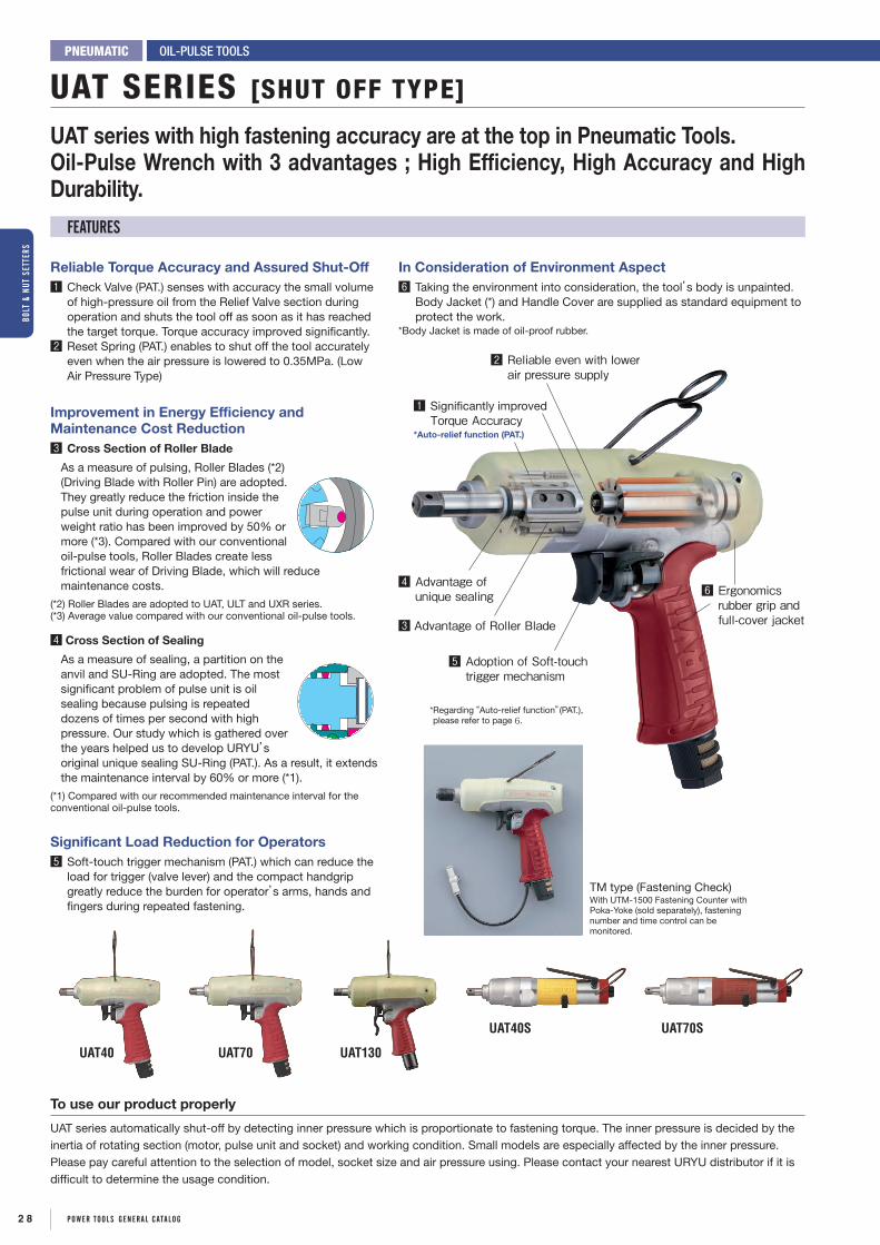
UAT40 UAT70 UAT130
UAT40S UAT70S
Reliable Torque Accuracy and Assured Shut-Off1 Check Valve (PAT.) senses with accuracy the small volume
of high-pressure oil from the Relief Valve section during operation and shuts the tool off as soon as it has reached the target torque. Torque accuracy improved significantly.
2 Reset Spring (PAT.) enables to shut off the tool accurately even when the air pressure is lowered to 0.35MPa. (Low Air Pressure Type)
Improvement in Energy Efficiency and Maintenance Cost Reduction3 Cross Section of Roller Blade
As a measure of pulsing, Roller Blades (*2) (Driving Blade with Roller Pin) are adopted. They greatly reduce the friction inside the pulse unit during operation and power weight ratio has been improved by 50% or more (*3). Compared with our conventional oil-pulse tools, Roller Blades create less frictional wear of Driving Blade, which will reduce maintenance costs.
(*2) Roller Blades are adopted to UAT, ULT and UXR series.(*3) Average value compared with our conventional oil-pulse tools.
4 Cross Section of Sealing
As a measure of sealing, a partition on the anvil and SU-Ring are adopted. The most significant problem of pulse unit is oil sealing because pulsing is repeated dozens of times per second with high pressure. Our study which is gathered over the years helped us to develop URYU’s original unique sealing SU-Ring (PAT.). As a result, it extends the maintenance interval by 60% or more (*1).
(*1) Compared with our recommended maintenance interval for the conventional oil-pulse tools.
Significant Load Reduction for Operators5 Soft-touch trigger mechanism (PAT.) which can reduce the
load for trigger (valve lever) and the compact handgrip greatly reduce the burden for operator’s arms, hands and fingers during repeated fastening.
UAT SERIES [SHUT OFF TYPE]
OIL-PULSE TOOLSPNEUMATIC
UAT series with high fastening accuracy are at the top in Pneumatic Tools.Oil-Pulse Wrench with 3 advantages ; High Efficiency, High Accuracy and High Durability.
FEATURES
TM type (Fastening Check)With UTM-1500 Fastening Counter with Poka-Yoke (sold separately), fastening number and time control can be monitored.
1 Significantly improved Torque Accuracy
*Auto-relief function (PAT.)
2 Reliable even with lower air pressure supply
6 Ergonomics rubber grip and full-cover jacket
4 Advantage of unique sealing
3 Advantage of Roller Blade
5 Adoption of Soft-touch trigger mechanism
* Regarding “Auto-relief function”(PAT.), please refer to page 6.
In Consideration of Environment Aspect6 Taking the environment into consideration, the tool’s body is unpainted.
Body Jacket (*) and Handle Cover are supplied as standard equipment to protect the work.
*Body Jacket is made of oil-proof rubber.
To use our product properly
UAT series automatically shut-off by detecting inner pressure which is proportionate to fastening torque. The inner pressure is decided by the inertia of rotating section (motor, pulse unit and socket) and working condition. Small models are especially affected by the inner pressure. Please pay careful attention to the selection of model, socket size and air pressure using. Please contact your nearest URYU distributor if it is difficult to determine the usage condition.
2 8 POWER TOOLS gEnERAL cATALOg
BOLT
& n
UT S
ETTE
RS

OIL-PULSE TOOLS
The model name suffixing (D) is the Quick-change driver anvil type.
On pulling the sleeve, insert or take off the bit.
6.35mm
9mm
Pistol Type Pistol TypeStraight Type Straight Type
Standard Type (0.5-0.6MPa) Low Air Pressure Type (0.4-0.5MPa)
2 types are available for different air pressure level.They can be distinguished by colors.
Quick-change driver anvil type
*Recommended Air Pressure for UAT30 and UAT40 series is 0.4-0.6MPa.
SPECIFICATIONS Recommended Air Pressure : 0.4MPa (57psi) ~ 0.6MPa (85psi)
Model
Capacity(Nominal Bolt Size)
Torque Range FreeSpeed
(Approx.)rpm
Overall Lengthless Socket
or Bit(about)
Weightless
Socket or Bit(about)
From Centerto Outside
(about)
Sq. Driveor
Hex. Size
AverageAir
Consumption Code0.4~0.5MPa 0.5~0.6MPa
mm in Nm ft-lbs Nm ft-lbs 0.4MPa 0.5MPa 0.6MPa mm in kg lb mm in mm in m3/min ft3/minUAT30D 4-5 No.8-No.10 2.5-5.5 1.85-4.07 2.5-5.5 1.85-4.07 3600 3800 4200 165 6 1/2 0.88 1.94 23.5 15/16 6.35 1/4 0.30 10.5 18A02UAT40 5 No.10 4.5-8.0 3.3-5.9 4.5-8.0 3.3-5.9 3300 3600 3800 162 6 3/8 0.92 2.0 24.5 31/32 9.5 3/8 0.25 8.8 18A42UAT40D 5 No.10 4.5-8.0 3.3-5.9 4.5-8.0 3.3-5.9 3300 3600 3800 165 6 1/2 0.92 2.0 24.5 31/32 6.35 1/4 0.25 8.8 18A62UAT50 6-8 1/4-5/16 - - 7.0-15.5 5.2-11.5 - 4400 4600 162 6 3/8 0.92 2.0 24.5 31/32 9.5 3/8 0.25 8.8 18B22UAT50D 6-8 1/4-5/16 - - 7.0-15.5 5.2-11.5 - 4400 4600 165 6 1/2 0.92 2.0 24.5 31/32 6.35 1/4 0.25 8.8 18B52UAT60 8 5/16 - - 15.0-32.0 11.1-23.7 - 6300 6700 174 6 27/32 0.95 2.1 24.5 31/32 9.5 3/8 0.35 12.3 18C82UAT60D 8 5/16 - - 15.0-32.0 11.1-23.7 - 6300 6700 177 6 31/32 0.95 2.1 24.5 31/32 6.35 1/4 0.35 12.3 18D12UAT70 8-10 5/16-3/8 - - 30.0-55.0 22.2-40.7 - 5700 6000 180 7 3/32 1.05 2.3 25.5 1 9.5 3/8 0.40 14.0 18E32UAT80 10-12 3/8-1/2 - - 45.0-63.0 33.3-46.6 - 5300 5600 186 7 5/16 1.25 2.8 28.0 1 3/32 9.5 3/8 0.48 16.8 18F22UAT90 10-12 3/8-1/2 - - 50.0-85.0 37.0-62.9 - 5400 5700 192 7 9/16 1.45 3.2 29.0 1 5/32 12.7 1/2 0.53 18.6 18F52UAT100 12-14 1/2 - - 70.0-130.0 51.8-96.2 - 4900 5200 199 7 27/32 1.70 3.7 31.5 1 1/4 12.7 1/2 0.55 19.3 18F82UAT130 14 9/16 - - 110-150 81.4-111 - 4300 4500 217 8 35/64 2.30 5.06 34.0 1 11/32 12.7 1/2 0.70 24.6 18G12UAT150 16 5/8 - - 140-210 103.6-155.4 - 3800 3900 240 9 29/64 2.90 6.4 38.0 1 1/2 19.0 3/4 0.70 24.6 18G42UAT180 16-18 5/8-3/4 - - 160-250 118.4-185.0 - 3100 3300 264 10 25/64 3.7 8.1 52.0 2 3/64 19.0 3/4 0.70 24.6 18G72UAT200 18-20 3/4 - - 200-400 148-296 - 2300 2400 279 10 63/64 5.80 12.76 49.5 1 31/32 19.0 3/4 1.00 35.2 18H32UAT50L 6-8 1/4-5/16 7.0-15.5 5.2-11.5 - - 4000 4300 - 162 6 3/8 0.92 2.0 24.5 31/32 9.5 3/8 0.25 8.8 18C12UAT50DL 6-8 1/4-5/16 7.0-15.5 5.2-11.5 - - 4000 4300 - 165 6 1/2 0.92 2.0 24.5 31/32 6.35 1/4 0.25 8.8 18B72UAT60L 8 5/16 13.0-28.0 9.6-20.7 - - 6000 6500 - 174 6 27/32 0.95 2.1 24.5 31/32 9.5 3/8 0.25 8.8 18D72UAT60DL 8 5/16 13.0-28.0 9.6-20.7 - - 6000 6500 - 177 6 31/32 0.95 2.1 24.5 31/32 6.35 1/4 0.25 8.8 18D32UAT70L 8-10 5/16-3/8 25.0-48.0 18.5-35.5 - - 5300 5600 - 180 7 3/32 1.05 2.3 25.5 1 9.5 3/8 0.30 10.5 18E82UAT80L 10-12 3/8-1/2 35.0-55.0 25.9-40.7 - - 5000 5300 - 186 7 5/16 1.25 2.8 28.0 1 3/32 9.5 3/8 0.40 14.0 18F32UAT90L 10-12 3/8-1/2 45.0-75.0 33.3-55.5 - - 5100 5600 - 192 7 9/16 1.45 3.2 29.0 1 5/32 12.7 1/2 0.45 15.8 18F62UAT100L 12 1/2 60.0-110.0 44.4-81.4 - - 4800 5200 - 199 7 27/32 1.70 3.7 31.5 1 1/4 12.7 1/2 0.48 16.8 18F92UAT130L 12-14 1/2-9/16 80.0-125.0 59.2-92.5 - - 4100 4400 - 217 8 35/64 2.30 5.06 34.0 1 11/32 12.7 1/2 0.50 17.6 18G22UAT150L 14-16 9/16-5/8 110.0-170.0 81.4-125.8 - - 3700 3800 - 240 9 29/64 2.9 6.4 38.0 1 1/2 19.0 3/4 0.50 17.6 18G52UAT180L 16 5/8 130.0-210.0 96.2-155.4 - - 3000 3100 - 264 10 25/64 3.7 8.1 52.0 2 3/64 19.0 3/4 0.50 17.6 18G82UAT200L 16-18 5/8-3/4 170.0-280.0 125.8-207.2 - - 2200 2300 - 279 10 63/64 5.80 12.76 49.5 1 31/32 19.0 3/4 0.70 24.6 18H42
Air Inlet Thread : NPT 1/4” for UAT30D-UAT150(L) Air Hose Size (Inside Diameter) : 6.5mm(1/4”) for UAT30D – UAT50 8.0mm(5/16”) for UAT60 – UAT100 NPT 3/8” for UAT180(L) 11.0mm(7/16”) for UAT100L – UAT180(L) 12.7mm(1/2”) for UAT200(L) *Torque Range is a guideline value. Please make tool selection appropriately in accordance with an actual application.
SPECIFICATIONS Recommended Air Pressure : 0.4MPa (57psi) ~ 0.6MPa (85psi)
Model
Capacity(Nominal Bolt Size)
Torque Range FreeSpeed
(Approx.)rpm
Overall Lengthless Socket
or Bit(about)
Weightless
Socket or Bit(about)
From Centerto Outside
(about)
Sq. Driveor
Hex. Size
AverageAir
Consumption Code0.4~0.5MPa 0.5~0.6MPa
mm in Nm ft-lbs Nm ft-lbs 0.4MPa 0.5MPa 0.6MPa mm in kg lb mm in mm in m3/min ft3/minUAT30SD 4-5 No.8-No.10 2.5-5.5 1.85-4.07 2.5-5.5 1.85-4.07 3100 3300 3400 222 8 47/64 0.75 1.94 21.5 27/32 6.35 1/4 0.35 12.3 18H12UAT40S 5 No.10 4.5-8.0 3.3-5.9 4.5-8.0 3.3-5.9 3000 3200 3300 224 8 13/16 0.85 1.9 22.5 7/8 9.5 3/8 0.20 7.0 18A92UAT40SD 5 No.10 4.5-8.0 3.3-5.9 4.5-8.0 3.3-5.9 3000 3200 3300 227 8 15/16 0.85 1.9 22.5 7/8 6.35 1/4 0.20 7.0 18B02UAT50S 6-8 1/4-5/16 - - 7.0-15.5 5.2-11.5 - 3700 3900 224 8 13/16 0.85 1.9 22.5 7/8 9.5 3/8 0.25 8.8 18C22UAT50SD 6-8 1/4-5/16 - - 7.0-15.5 5.2-11.5 - 3700 3900 227 8 15/16 0.85 1.9 22.5 7/8 6.35 1/4 0.25 8.8 18C32UAT60S 8 5/16 - - 15.0-32.0 11.1-23.7 - 5400 5700 229 9 0.87 1.9 22.5 7/8 9.5 3/8 0.30 10.5 18D82UAT60SD 8 5/16 - - 15.0-32.0 11.1-23.7 - 5400 5700 232 9 1/8 0.87 1.9 22.5 7/8 6.35 1/4 0.30 10.5 18D92UAT70S 8-10 5/16-3/8 - - 30.0-50.0 22.2-37.0 - 4400 4700 239 9 13/32 0.95 2.1 23.5 7/8 9.5 3/8 0.35 12.3 18E92UAT50SL 6-8 1/4-5/16 7.0-15.5 5.2-11.5 - - 3800 4000 - 224 8 13/16 0.85 1.9 22.5 7/8 9.5 3/8 0.20 7.0 18C52UAT50SDL 6-8 1/4-5/16 7.0-15.5 5.2-11.5 - - 3800 4000 - 227 8 15/16 0.85 1.9 22.5 7/8 6.35 1/4 0.20 7.0 18C42UAT60SL 8 5/16 13.0-28.0 9.6-20.7 - - 5300 5600 - 229 9 0.87 1.9 22.5 7/8 9.5 3/8 0.25 8.8 18E12UAT60SDL 8 5/16 13.0-28.0 9.6-20.7 - - 5300 5600 - 232 9 1/8 0.87 1.9 22.5 7/8 6.35 1/4 0.25 8.8 18E02UAT70SL 8-10 5/16-3/8 25.0-45.0 18.5-33.3 - - 4400 4700 - 239 9 13/32 0.95 2.1 23.5 7/8 9.5 3/8 0.27 9.5 18F02
Air Inlet Thread : NPT 1/4” Air Hose Size (Inside Diameter) : 6.5mm(1/4”) for UAT30SD – UAT50S 8.0mm(5/16”) for UAT60S – UAT70S *Torque Range is a guideline value. Please make tool selection appropriately in accordance with an actual application.
SPECIFICATIONS Recommended Air Pressure:0.6MPa(85psi)
ModelCapacity
(Nominal Bolt Size) Torque Range
FreeSpeed(about)
rpm
Overall Lengthless Socket
or Bit(about)
Weightless
Socket or Bit(about)
From Centerto Outside
(about)
Sq. Driveor
Hex. Size
AverageAir
Consumption Code
mm in Nm ft-lbs 0.5MPa 0.6MPa mm in kg lb mm in mm in m3/min ft3/minUXR-T2400S 24 7/8 360-650 260-470 3400 3600 444 17 31/64 12.00 26.46 61.5 2 27/64 25.4 1 1.00 35.3 16522UXR-T3000S 30 1 1/8 450-850 330-620 4200 4400 477 18 25/32 14.50 31.97 62.0 2 7/16 25.4 1 1.05 37.1 17022
Air Inlet Thread : NPT1/2" Air Hose Size : 12.7mm (1/2") Inside Trigger is available*Torque Range is a guideline value. Please make tool selection appropriately in accordance with an actual application.
UXR-T SERIES
2 9POWER TOOLS gEnERAL cATALOg
BOLT & nUT SETTERS

UL70UL30
UL100UL50 UL150
UL80
6.35mm
9mm
UL50S
UL40SUL30S
UL70SUL60S
Quick-change driver anvil typeOn pulling the sleeve, insert or take off the bit.
The model name suffixing (D) is the Quick-change driver anvil type.
PNEUMATIC
Ultralight Oil-Pulse Tool. Reduce the burden on the operators.
UL SERIES [NON SHUT-OFF TYPE]
OIL-PULSE TOOLS
SPECIFICATIONS Recommended Air Pressure : 0.5MPa (72psi) - 0.6MPa (85psi)
ModelCapacity
(Nominal Bolt Size)
Torque Range FreeSpeed
(Approx.)rpm
Overall LengthLess Socket
or Bit(Approx.)
Weightless
Socket or Bit(Approx.)
From Centerto Outside(Approx.)
Sq. Driveor
Hex. Size
AverageAir
Consumption Code0.5MPa 0.6MPa
mm in Nm ft-lbs Nm ft-lbs 0.5MPa 0.6MPa mm in kg lb mm in mm in m3/min ft3/min
UL30 5 No.10 5.5-10.5 4.1-7.8 6-12 4.4-8.9 5400 5700 133 5 15/64 0.70 1.5 20.5 13/16 9.5 3/8 0.20 7.0 14282
UL30D 5 No.10 5.5-10.5 4.1-7.8 6-12 4.4-8.9 5400 5700 137 5 25/64 0.70 1.5 20.5 13/16 6.35 1/4 0.20 7.0 14292
UL40 5-6 No.10-1/4 11-20 8.1-14.8 13-22 9.6-16.3 5800 6100 133 5 15/64 0.70 1.5 20.5 13/16 9.5 3/8 0.20 7.0 14302
UL40D 5-6 No.10-1/4 9-17 6.7-12.6 11-20 8.1-14.8 5800 6100 137 5 25/64 0.70 1.5 20.5 13/16 6.35 1/4 0.20 7.0 14322
UL50 6-8 1/4-5/16 20-32 14.8-23.7 22-35 16.3-25.9 6100 6400 140 5 33/64 0.77 1.7 22.0 55/64 9.5 3/8 0.30 10.5 14332
UL50D 6-8 1/4-5/16 16-25 11.8-18.5 18-28 13.3-20.7 6100 6400 146 5 3/4 0.77 1.7 22.0 55/64 6.35 1/4 0.30 10.5 14352
UL60 8 5/16 30-45 22.2-33.3 32-50 23.7-37.0 6700 7000 140 5 33/64 0.82 1.8 22.0 55/64 9.5 3/8 0.40 14.0 14362
UL60D 8 5/16 20-32 14.8-23.7 22-35 16.3-25.9 6700 7000 143 5 5/8 0.82 1.8 22.0 55/64 6.35 1/4 0.40 14.0 14372
UL70 8-10 5/16-3/8 36-60 26.6-44.4 40-65 29.6-48.1 5400 5700 153 6 1/32 0.95 2.1 23.0 29/32 9.5 3/8 0.45 15.8 14382
* UL80 10-12 3/8-1/2 40-55 29.6-40.7 45-70 33.3-50.0 5600 5900 162 6 3/8 1.15 2.5 26.0 1 1/32 9.5 3/8 0.48 16.8 11722
UL90 10-12 3/8-1/2 55-90 40.7-66.6 60-100 44.4-74.0 5700 6000 170 6 11/16 1.30 2.9 27.0 1 1/16 12.7 1/2 0.53 18.6 14392
UL100 12-14 1/2 72-120 53.3-88.8 80-130 59.2-96.2 5100 5400 177 6 31/32 1.66 3.7 29.5 1 5/32 12.7 1/2 0.58 20.3 15502
UL130 14 9/16 90-145 66.6-107.3 100-160 74.0-118.4 4200 4400 197 7 3/4 2.30 5.1 32.0 1 17/64 12.7 1/2 0.65 22.7 14102
UL150 16 5/8 135-210 99.6-154.7 150-230 109.9-169.6 3500 3800 213 8 25/64 3.00 6.6 36.0 1 27/64 19.0 3/4 0.70 24.7 11482
UL30S 5 No.10 5.5-10.5 4.1-7.8 6-12 4.4-8.9 4700 5000 205 8 5/64 0.62 1.4 20.5 51/64 9.5 3/8 0.23 8.1 10622
UL30SD 5 No.10 5.5-10.5 4.1-7.8 6-12 4.4-8.9 4700 5000 209 8 15/64 0.62 1.4 20.5 51/64 6.35 1/4 0.23 8.1 10632
UL40S 5-6 No.10-1/4 11-20 8.1-14.8 11-22 8.1-16.3 4700 5000 205 8 5/64 0.62 1.4 20.5 51/64 9.5 3/8 0.23 8.1 10652
UL40SD 5-6 No.10-1/4 9-17 6.7-12.6 9-20 6.7-14.8 4700 5000 209 8 15/64 0.62 1.4 20.5 51/64 6.35 1/4 0.23 8.1 10662
UL50S 6-8 1/4-5/16 20-32 14.8-23.7 22-35 16.3-25.9 6100 6400 208 8 3/16 0.74 1.6 22.0 7/8 9.5 3/8 0.35 12.3 10682
UL50SD 6-8 1/4-5/16 16-25 11.8-18.5 18-28 13.3-20.7 6100 6400 214 8 27/64 0.74 1.6 22.0 7/8 6.35 1/4 0.35 12.3 10692
UL60S 8 5/16 30-45 22.2-33.3 32-50 23.7-37.0 6400 6700 209 8 15/64 0.77 1.7 22.0 7/8 9.5 3/8 0.45 15.8 10722
UL60SD 8 5/16 20-32 14.8-23.7 22-35 16.3-25.9 6400 6700 212 8 11/32 0.77 1.7 22.0 7/8 6.35 1/4 0.45 15.8 10732
UL70S 8-10 5/16-3/8 36-60 26.6-44.4 36-60 26.6-44.4 5100 5400 223 8 25/32 0.87 1.9 23.5 59/64 9.5 3/8 0.40 14 10752
Air Inlet Size : NPT1/4"Air Hose Size : 10mm×6.5mm×5m for UL30-50 12mm×8.0mm×5m for UL60-150Air Hose Size : 10mm×6.5mm×5m for UL30S-50S 12mm×8.0mm×5m for UL60S-70S*Please refrain from using UL80 at around max. torque as it is developed to aim at torque output between UL70 & UL90.*Torque Range is a guideline value. Please make tool selection appropriately in accordance with an actual application.
3 0 POWER TOOLS gEnERAL cATALOg
BOLT
& n
UT S
ETTE
RS

PNEUMATIC
Easy to operate in narrow area.Reliable fastening with oil-pulse wrench.
ULT50C ULT70CH
CORNER TYPE ULT / UX SERIES
OIL-PULSE TOOLS
★To do torque adjustment...Remove the Hammer Casing Nut and confirm you seethe Relief Valve Spindle through the hole. Use AllenWrench (1.5mm) to adjust torque. Turn the ReliefValve Spindle clockwise to increase tightening torqueand anti-clockwise to decrease tightening torque. Fixthe Hammer Casing Nut firmly after adjustment.
H
C
←Remove this way
SPECIFICATIONS Recommended Air Pressure : 0.4MPa (57psi) - 0.6MPa (85psi)
ModelCapacity
(Nominal Bolt Size)
Torque Range FreeSpeed
(Approx.)rpm
Overall Lengthless Socket
or Bit(about)
Weightless
Socket or Bit(about)
From Centerto Outside
(about)
Sq. Driveor
Hex. Size
AverageAir
Consumption Code0.4~0.5MPa 0.5~0.6MPa
mm in Nm ft-lbs Nm ft-lbs 0.4MPa 0.6MPa mm in kg lb mm in mm in m3/min ft3/min
ULT40C 5 No.10 - - 4.5-7.5 3.33-5.55 3300 3500 250 9 27/32 1.30 2.9 24.5 31/32 9.5 3/8 0.20 7.0 12692
ULT50C 6-8 1/4-5/16 - - 7.0-15.5 5.2-11.5 - 4500 250 9 27/32 1.35 3.0 24.5 31/32 9.5 3/8 0.25 8.6 12732
ULT60C 8 5/16 - - 13-28 9.6-20.7 - 5200 261 10 9/32 1.45 3.2 24.5 31/32 9.5 3/8 0.30 10.5 12752
ULT70C 8 5/16 - - 20-35 14.8-25.9 - 4400 275 10 53/64 1.65 3.6 26.5 1 3/64 9.5 3/8 0.35 12.3 12772
ULT70CH 8-10 5/16-3/8 - - 30-50 22.2-37.0 - 2500 290 11 27/64 1.85 4.1 26.5 1 3/64 12.7 1/2 0.35 12.3 11292
ULT50CL 6-8 1/4-5/16 7.0-15.5 5.2-11.5 - - 4500 - 250 9 27/32 1.35 3.0 24.5 31/32 9.5 3/8 0.20 7.0 12742
ULT60CL 8 5/16 13-28 9.6-20.7 - - 5200 - 261 10 9/32 1.45 3.2 24.5 31/32 9.5 3/8 0.25 8.6 12762
ULT70CL 8 5/16 20-35 14.8-25.9 - - 4300 - 275 10 53/64 1.65 3.6 26.5 1 3/64 9.5 3/8 0.27 9.5 12782
ULT70CHL 8-10 5/16-3/8 30-50 22.2-37.0 - - 2300 - 290 11 27/64 1.85 4.1 26.5 1 3/64 12.7 1/2 0.27 9.5 11302
Air Inlet Size : NPT 1/4"Air Hose Size : 10mm×6.5mm×5m for ULT40C〜50C(L) 12mm×8.0mm×5m for ULT60C〜70C(L) , and 70CH(L)*Torque Range is a guideline value. Please make tool selection appropriately in accordance with an actual application.
ModelH C
mm in mm in
ULT40C 59 2 21/64 16 5/8
ULT50C 59 2 21/64 16 5/8
ULT60C 59 2 21/64 16 5/8
ModelH C
mm in mm in
ULT70C 70 2 3/4 18 45/64
ULT70CH 77 3 1/32 22 7/8
Head Sizes
Standard Type (0.5〜0.6MPa)
Low Air Pressure Type (0.4〜0.5MPa)
2 types are available for different air pressure level.They can be distinguished by colors.
UX-500C
UX-612A
UX-800C UX-1000C
C
H
Head SizesModel
C Hmm in mm in
UX-500C 15.0 19/32 59.5 2 11/32
UX-612C 16.0 5/8 59.5 2 11/32
UX-700C 16.0 5/8 62.0 2 7/16
UX-800C 18.0 45/64 70.0 2 3/4
UX-900C 18.0 45/64 70.0 2 3/4
UX-1000C 21.5 27/32 80.0 3 5/32
SPECIFICATIONS Recommended Air Pressure : 0.6MPa (85psi)
ModelCapacity
(Nominal Bolt Size)
Torque Range FreeSpeed
(Approx.)rpm
OverallLength(about)
Weightless
Socket or Bit(about)
Angle Height(about)
Sq. Driveor
Hex. Size
AverageAir
Consumption Code0.5MPa 0.6MPa
mm in Nm ft-lbs Nm ft-lbs 0.5MPa 0.6MPa mm in kg lb mm in mm in m3/min ft3/min
UX-500C 5-6 No. 10-1/4 11-17 8.0-12.5 13-20 10.0-15.0 8800 9300 270 10 5/8 1.28 2.8 59.5 2 11/32 9.5 3/8 0.25 8.8 17792
UX-612C 6 1/4 13.5-24 9.9-17.7 16-28 12.0-20.0 9300 9800 283 11 9/64 1.38 3.0 59.5 2 11/32 9.5 3/8 0.32 11.2 17942
UX-700C 8 5/16 17-31 12.5-22.8 20-36 16.0-28.0 9000 9500 273 10 3/4 1.67 3.7 62.0 2 7/16 9.5 3/8 0.35 12.3 17952
UX-800C 8-10 5/16-3/8 25-36 18.4-26.5 29-43 20.0-31.0 8500 9000 285 11 7/32 1.93 4.3 70.0 2 3/4 9.5 3/8 0.40 14.1 17962
UX-900C 10 3/8 30-47 22.1-34.6 35-55 25.0-40.0 7300 7600 338 13 5/16 2.25 5.0 70.0 2 3/4 9.5 3/8 0.42 14.9 17972
UX-1000C 10-12 3/8-1/2 43-68 31.7-50.1 50-80 40.0-58.0 6600 6800 365 14 3/8 3.05 6.8 80.0 2 5/32 12.7 1/2 0.51 17.9 17982
UX-612A 6 1/4 13.5-24 9.9-17.7 16-28 12.0-20.0 9300 9800 297 11 11/16 1.38 3.0 - - 9.5 3/8 0.30 10.5 17802
Air Inlet size : NPT1/4"Air Hose Size : 6.35mm (1/4") for UX-500C 9.5mm (3/8") for UX-612C~UX-1000C*Torque Range is a guideline value. Please make tool selection appropriately in accordance with an actual application.
ULT SERIES [SHUT OFF TYPE]
UX SERIES [NON SHUT-OFF TYPE]
3 1POWER TOOLS gEnERAL cATALOg
BOLT & nUT SETTERS

The model name suffixing (D) is the Quick-change driver anvil type.
U / UX / UXR / UX-ST SERIES [NON SHUT-OFF TYPE]
OIL-PULSE TOOLSPNEUMATIC
U-Wrench was released in 1978, UX-Wrench was released in 1984.Our long-selling tools proud reliability and achievements.
UX-ST1000
UX-ST800
Auto-reversing mechanismThese unique Push-Pull type Oil-Pulse tools simplify stud-bolt driving job considerably without any special operation for frequent reversing. Push the tool forward to the application for driving and simply pull back for automatic reversing.
FEATURES
STUD BOLT WRENCHES
SPECIFICATIONS Recommended Air Pressure : 0.6MPa (85psi)
ModelCapacity
(Nominal Bolt Size)
Torque Range FreeSpeed
(Approx.)rpm
OverallLength(about)
Weightless
Socket or Bit(about)
From Centerto Outside
(about)
Sq. Driveor
Hex. Size
AverageAir
Consumption Code0.5MPa 0.6MPa
mm in Nm ft-lbs Nm ft-lbs 0.5MPa 0.6MPa mm in kg lb mm in mm in m3/min ft3/minUX-900S 10 3/8 38-64 28-47.2 45-75 35-55 7300 7600 310 12 13/64 1.80 3.9 37.5 1 9/64 12.7 1/2 0.42 14.9 18072UX-1000S 10-12 3/8-1/2 43-81 31.7-59.8 50-95 40-70 6500 6800 320 12 19/32 2.10 4.6 39.0 1 17/64 12.7 1/2 0.51 17.9 18082UX-1300S 13-14 1/2-9/16 68-110 50.2-81.2 80-130 60-95 5800 6200 336 13 15/64 2.55 6.6 42.0 1 11/32 12.7 1/2 0.55 19.4 18092UXR-2000S 18-20 3/4 255-385 188-284 300-450 220-330 4000 4200 340 13 25/64 7.00 15.4 47.0 1 27/32 19.0 3/4 0.90 31.6 17632UXR-2400S 24 7/8 340-550 251-406 400-650 290-470 3700 4000 385 15 5/32 11.00 23.7 55.0 2 1/8 25.4 1 1.00 35.2 17692UXR-3000S 30 1/4 425-725 313-535 500-850 360-630 4200 4400 455 17 29/32 13.30 29.3 62.0 2 1/8 25.4 1 1.05 37.1 17532
Air Inlet Size : NPT1/4" for UX-900S~UX-1300S NPT3/8" for UXR-2000S NPT1/2" for UXR-2400S & UXR-3000S
Inside Trigger is available for UXR-2000S~UXR-3000SAir Hose Size : 9.5mm (3/8") for UX-900S~UX-1300S
12.7mm (1/2") for UXR-2000S~UXR-3000S
* Torque Range is a guideline value. Please make tool selection appropriately in accordance with an actual application.
SPECIFICATIONS Recommended Air Pressure : 0.6MPa (85psi)
ModelCapacity
(Nominal Bolt Size)
Torque Range FreeSpeed
(Approx.)rpm
OverallLength(about)
Weightless
Socket or Bit(about)
From Centerto Outside
(about)
Sq. Driveor
Hex. Size
AverageAir
Consumption Code0.5MPa 0.6MPa
mm in Nm ft-lbs Nm ft-lbs 0.5MPa 0.6MPa mm in kg lb mm in mm in m3/min ft3/min
UX-ST800 8-10 5/16-3/8 30-47 22-35 35-55 25-40 7000 7300 195 7 43/64 1.75 3.8 28.0 1 3/32 9.5 3/8 0.30 10.5 18322
UX-ST1000 10-12 3/8-1/2 43-77 32-57 50-90 40-65 6000 6300 210 8 17/64 2.50 5.5 33.0 1 19/64 12.7 1/2 0.48 16.8 18342
6.35mm
9mmQuick-change driver anvil typeOn pulling the sleeve,insert or take off the bit.
Air Inlet Thread : NPT1/4" for U-350D NPT3/8" for UXR-1820 & UXR-2000
SPECIFICATIONS Recommended Air Pressure : 0.6MPa (85psi)
ModelCapacity
(Nominal Bolt Size)
Torque Range FreeSpeed
(Approx.)rpm
OverallLength(about)
Weightless
Socket or Bit(about)
From Centerto Outside
(about)
Sq. Driveor
Hex. Size
AverageAir
Consumption Code0.5MPa 0.6MPa
mm in Nm ft-lbs Nm ft-lbs 0.5MPa 0.6MPa mm in kg lb mm in mm in m3/min ft3/minU-310SD 3-4 No.5-No.8 2.1-2.6 1.6-1.9 2.5-3.1 1.8-2.2 10000 11000 222 8 47/64 0.62 1.5 18.0 47/64 6.35 1/4 0.15 5.3 19662U-350SD 3-4 No.5-No.8 3.0-5.0 2.2-3.7 3.5-5.8 2.5-4.2 10000 10500 238 9 3/8 0.71 1.5 22.0 47/64 6.35 1/4 0.15 5.3 19332U-350D 3-4 No.5-No.8 3.0-5.0 2.2-3.7 3.5-5.8 2.5-4.2 10000 10500 154 6 1/16 0.77 1.7 22.0 7/8 6.35 1/4 0.15 5.3 19242UXR-1820 16-18 5/8-3/4 135-215 99.6-158.7 160-250 120-185 4400 4600 242 9 17/32 4.10 9.0 42.0 1 21/32 19.0 3/4 0.75 26.3 17322UXR-2000 18-20 3/4 255-385 188.2-284.1 300-450 220-330 4000 4200 282 11 7/64 6.50 14.3 47.0 1 27/32 19.0 3/4 0.90 31.5 17602
Air Hose Size : 6.35mm (1/4") for U-350D 12.7mm (1/2") for UXR-1820 & UXR-2000
* Torque Range is a guideline value. Please make tool selection appropriately in accordance with an actual application.
UX-900S U-310SD
UXR-1820
R
LLeft rotation
Right rotation
R
LLeft rotation
Right rotation
CUSTOM-MADE M0DELS *These Models are specially designed for user’s request.
Air Inlet Size: NPT1/4"Air Hose Size: 9.5mm (3/8")
* Torque Range is a guideline value. Please make tool selection appropriately in accordance with an actual application.
3 2 POWER TOOLS gEnERAL cATALOg
BOLT
& n
UT S
ETTE
RS

RATCHET WRENCHESBolt & Nut SetterS
Most suitable for fastening in narrow application. Bent head type, Thinner head type and Extended head type are also avai lable for hard-to-reach access fastening jobs.Reverse rotation is obtained by simply turning a tool over.
FEATURES
Head Sizes
ModelH W l C
mm in mm in mm in mm in
URW-6,60,60R 13.0 33/64 20.0 25/32 88.0 3 15/32 10.0 25/64
URW-8,8N,9N,80,80R,81,81R 18.0 45/64 25.0 63/64 102.5 4 1/32 12.5 31/64
URW-10N 18.0 45/64 33.0 1 19/64 106.5 4 3/16 16.5 21/32
URW-12N 18.0 45/64 36.0 1 27/64 109.5 4 5/16 18.0 45/64
URW-12NA 18.0 45/64 46.0 1 13/16 120.5 4 3/4 23.0 29/32
URW-12NB 18.0 45/64 54.0 2 1/8 128.5 5 1/16 27.0 1 1/16
(W)(O)(H)
(C)
(H)
(C)(L)
(W)
(W)(H)
URW-8
URW-10N
URW-8N URW-12NB
URW-6 URW-12N
URW-60URW-80URW-81(Left Rotation)
URW-60RURW-80RURW-81R(Right Rotation)
URW-60 • URW-60R : 160°URW-80 • URW-80R : 160°URW-81 • URW-81R : 150°
SPeCIFICAtIoNS Recommended Air Pressure : 0.4MPa (57psi)
ModelCapacity
(Nominal Bolt Size) Max. torqueFree
Speed(about)
overall length(about)
Weight(about) Hex. Size of ratchet
Average Air
Consumption Code
mm in Nm ft-lbs rpm mm in kg lb mm in m3/min ft3/min
URW-6 6 1/4 11 8.1 210 292 11 1/2 1.15 2.53 6, 7, 8, ⑩, 11, 12 1/4, 5/16, 3/8, 7/16 0.28 9.9 20052
URW-60 6 1/4 11 8.1 210 288 11 11/32 1.15 2.53 6, 7, 8, ⑩, 11, 12 1/4, 5/16, 3/8, 7/16 0.28 9.9 20082
URW-60R 6 1/4 11 8.1 210 288 11 11/32 1.15 2.53 6, 7, 8, ⑩, 11, 12 1/4, 5/16, 3/8, 7/16 0.28 9.9 20092
URW-8N 8 5/16 16 11.8 260 300 11 13/16 2.25 4.95 7, 8, 9, 10, 11, 12, 13, ⑭, 15 7/16, 1/2, 9/16 0.55 19.5 21212
URW-80 8 5/16 16 11.8 240 300 11 13/16 2.25 4.95 7, 8, 9, 10, 11, 12, 13, ⑭, 15 7/16, 1/2, 9/16 0.55 19.5 22912
URW-80R 8 5/16 16 11.8 240 300 11 13/16 2.25 4.95 7, 8, 9, 10, 11, 12, 13, ⑭, 15 7/16, 1/2, 9/16 0.55 19.5 22962
URW-81 8 5/16 16 11.8 240 300 11 13/16 2.25 4.95 7, 8, 9, 10, 11, 12, 13, ⑭, 15 7/16, 1/2, 9/16 0.55 19.5 23112
URW-81R 8 5/16 16 11.8 240 300 11 13/16 2.25 4.95 7, 8, 9, 10, 11, 12, 13, ⑭, 15 7/16, 1/2, 9/16 0.55 19.5 23162
URW-8 8 5/16 16 11.8 240 360 14 3/16 1.90 4.18 7, 8, 9, 10, 11, 12, 13, ⑭, 15 7/16, 1/2, 9/16 0.56 19.8 20152
URW-9N 10 3/8 31 22.9 140 380 15 2.35 5.17 7, 8, 9, 10, 11, 12, 13, ⑭, 15 7/16, 1/2, 9/16 0.67 23.7 22742
URW-10N 10 3/8 57 42.2 155 394 15 33/64 2.65 5.83 10, 12, 13, 14, 15, 16, ⑰, 18, 19 9/16, 5/8, 11/16, 3/4 0.70 25.0 21412
URW-12N 13 1/2 59 43.7 145 397 15 5/8 2.70 5.94 12, 14, 16, 17, 18, 19, �, 22, 23 3/8, 1/2, 9/16, 5/8, 11/16, 3/4, 13/16 0.70 25.0 21512
URW-12NA 14 9/16 78 57.7 105 408 16 1/16 2.80 6.16 17, 18, 19, 21, 22, 23, �, 26, 27 11/16, 3/4, 15/16 0.70 25.0 21612
URW-12NB 16 5/8 93 68.8 90 416 16 19/64 2.90 6.38 24, 29, �, 32 5/8, 11/16, 3/4, 13/16, 7/8, 15/16, 1, 1-1/8 0.70 25.0 21812
Air Inlet Thread (Pipe Tap) : NPT1/4"Air Hose Size (Inside Diameter) : 9.5mm (3/8")Code mentioned in the above list comes with the standard Hex size of ratchet circled ○ . Specify Hex. size when ordering.Max Torque is a guideline at 0.6MPa.
3 3POWER TOOLS gEnERAL cATALOg
BOLT & nUT SETTERS

UGW-8N
UOW-11-10
UOW-11-14
UOW-11-22
UOW-11-30 UOW-T60-22
(OPEN-END WRENCHES)URYU offers two types of Open-End Wrenches for fast, accurate tube nut tightening. UOW-11 series is a stall torque type and UOW-T60 series is a mechanical shut-off type with external torque adjustment.
(GEARED WRENCHES)Gear drive mechanism amplifies and transmits the motor rotation power. UGW Geared Wrench offers quiet operation with good durability.
FEATURES
OPEN-END WRENCHES / GEARED WRENCHESBolt & Nut SetterS
SPeCIFICAtIoNS Recommended Air Pressure : 0.6MPa (85psi)
ModelMax.
torque / range
FreeSpeed(about)
overall length(about)
Weight(about) Hex. Size of Gear Socket
Average Air
Consumption Code
Nm ft-lbs rpm mm in kg lb mm in m3/min ft3/min
UOW-11-10 13 9.6 390 295 11 47/64 1.50 3.31 7, 8, 9, ⑩, 11, 12 1/4, 5/16, 3/8, 7/16 0.30 10.5 23502
UOW-11-14 16 11.8 290 311 12 1/4 1.60 3.52 10, 11, 12, 13, ⑭, 15, 16, 17 7/16, 1/2, 9/16, 5/8 0.30 10.5 23542
UOW-11-22 24 17.8 220 326 12 53/64 1.75 3.85 11, 12, 13, 14, 15, 16, 17, 18, 19, 20, 21, �, 24 7/16, 1/2, 9/16, 5/8, 11/16, 3/4, 13/16, 7/8 0.30 10.5 23602
UOW-11-30 32 23.7 160 347 13 21/32 2.00 4.40 14, 17, 18, 19, 23, 24, 26, 27, 29, �, 32 5/8, 11/16, 3/4, 13/16, 7/8, 15/16, 1, 1-1/8, 1-3/16 0.30 10.5 23662
UOW-T60-10 4-14 3.0-10.4 300 370 14 5/8 2.10 4.62 7, 8, 9, ⑩, 11, 12 1/4, 5/16, 3/8, 7/16 0.30 10.5 24202
UOW-T60-14 5-17 3.7-12.6 240 385 15 1/8 2.20 4.85 10, 11, 12, 13, ⑭, 15, 16, 17 7/16, 1/2, 9/16, 5/8 0.30 10.5 24222
UOW-T60-22 7-24 5.2-17.8 170 400 15 3/4 2.35 5.18 11, 12, 13, 14, 15, 16, 17, 18, 19, 20, 21, �, 24 7/16, 1/2, 9/16, 5/8, 11/16, 3/4, 13/16, 7/8 0.30 10.5 24242
UOW-T60-30 10-32 7.4-23.7 130 420 16 5/8 2.60 5.73 14, 17, 18, 19, 23, 24, 26, 27, 29, �, 32 5/8, 11/16, 3/4, 13/16, 7/8, 15/16, 1, 1-1/8, 1-3/16 0.30 10.5 24262
UGW-6N 18 13.3 530 310 12 13/64 1.40 3.08 9, ⑩, 11, 12 0.30 10.5 24602
UGW-8N 23 17.0 410 322 12 11/16 1.45 3.19 10, 12, 13, ⑭, 17 0.30 10.5 24652
Air Inlet Thread (Pipe Tap) : NPT1/4" Air Hose Size (Inside Diameter) : 9.5mm (3/8")Code mentioned in the above list comes with the standard Hex size of gear socket circled ○ . Specify Hex. size when ordering.
Head Sizes ModelH W o C
mm in mm in mm in mm in
UOW-11-10,UOW-T60-10 14.0 35/64 37.0 1 29/64 5.0~6.0 13/64~15/64 10.0 25/64
UOW-11-14,UOW-T60-14 14.0 35/64 40.0 1 37/64 6.0~9.0 15/64~23/64 13.0 33/64
UOW-11-22,UOW-T60-22 16.0 5/8 56.0 2 13/64 13.0~15.0 33/64~19/32 17.0 43/64
UOW-11-30,UOW-T60-30 16.0 5/8 68.0 2 43/64 15.0~23.0 19/32~29/32 21.0 53/64
UGW-6N 14.0 35/64 32.0 1 17/64 - - 12.9 33/64
UGW-8N 14.0 35/64 36.0 1 27/64 - - 15.8 39/64
(W)(O)(H)
(C)
(H)
(C)(L)
(W)
(W)(H)
UOW-T60 series only.
1 : Min.
3 : Max.
Push down the self-locking lever to operate tool as above.➡
Safety Start Lever Safety Start Lever is installed as standard equipment for UOW series to prevent accidental start of tool.
EXTERNAL DIALTorque adjustment. (No special tool is needed)
3 4 POWER TOOLS gEnERAL cATALOg
BOLT
& n
UT S
ETTE
RS

Instant automatic shut-off providing reduced reaction.Low inertia design providing increased accuracy.
FEATURES
• Simple and accurate method to adjust torque output by Phillips Driver permitting quick setup.
• Designed with a spline type interface allowing multiple head positions for the most comfortable throttle location on those hard to reach applications.
• The pneumatic motor is designed to offer high power performance by reducing motor inertia to the minimum level.
• Ergonomically designed Protector offers firm gripping for ergonomic fastening.
ANGLE NUTRUNNERSBolt & Nut SetterS
System Layout For Torque Monitoring Type
UAN-611RM TORQUE MONITORING TYPE
SPeCIFICAtIoNS Recommended Air Pressure : 0.6MPa (85psi)
ModelBolt Capacity torque range
FreeSpeed(about)
overalllength
less Socket(about)
Weightless
Socket(about)
From Centerto outside
(about)
Angle Height(about)
Square DriveShank
AverageAir
Consumption Code
mm in Nm ft-lbs rpm mm in kg lb mm in mm in mm in m3/min ft3/min
UAN-611RM-60C 6 1/4 6.5-12.0 4.3-8.6 620 419 16 1/2 2.0 4.4 14.0 35/64 47 1 55/64 9.5 3/8 0.6 21.2 26852
UAN-611RM-50C 6-8 1/4-5/16 8.5-15.0 5.7-10.8 470 409 16 7/64 2.0 4.4 14.0 35/64 47 1 55/64 9.5 3/8 0.6 21.2 26842
UAN-611RM-40C 6-8 1/4-5/16 10.0-18.0 7.2-12.9 400 409 16 7/64 2.0 4.4 14.0 35/64 47 1 55/64 9.5 3/8 0.6 21.2 26832
UAN-611RM-30C 8 5/16 13.0-25.0 9.3-18.0 270 409 16 7/64 2.0 4.4 14.0 35/64 47 1 55/64 9.5 3/8 0.6 21.2 26822
UAN-701RM-60C 8 5/16 20.0-31.0 14.5-23.1 600 480 18 57/64 2.7 5.94 14.0 35/64 47 1 55/64 9.5 3/8 0.9 31.8 27032
UAN-701RM-40C 8-10 5/16-3/8 28.0-45.0 21.0-33.3 400 492 19 3/8 2.9 6.38 18.0 45/64 51 2 9.5 3/8 0.9 31.8 27022
UAN-701RM-30C 10-12 3/8-1/2 37.0-60.0 27.5-44.1 300 492 19 3/8 2.9 6.38 18.0 45/64 58 2 9/32 12.7 1/2 0.9 31.8 27012
Air Inlet Thread (Pipe Tap) : NPT1/4" Air Hose Size (Inside Diameter) : 9.5mm (3/8")*Torque Range is a guideline value. Please make tool selection appropriately in accordance with an actual application.
Controller : UEC-4800(SD)/UEC-4800TP(SD)
UEC-4800TP
MADE IN JAPAN
UEC-4800
Sensor Cable Assembly5M (Part Number : 910-316-0)
Rear PanelFront Panel
AC100-230V 50/60Hz 0.35A
AC250V T3.15AFUSE
SENSORS.G M.S
miniSD CARD
NETWORK
URYU SEISAKU,LTD.JAPAN
PC
COMOUT OUT2
OUT1OUT4
OUT3 OUT5 OUT6 COMOUT+24V
VALVE
COMIN IN1
IN2IN3
IN4IN5
IN6 COMINCOM
INCOMOUT OUTPUT
ANALOG
CN-1
PC
TORQUE CONTROLLER
POWER
4800UEC
V .. .URYU
SPeCIFICAtIoNS Recommended Air Pressure : 0.6MPa (85psi)
ModelBolt Capacity torque range
FreeSpeed(about)
overalllength(about)
Weightless
Socket(about)
From Centerto outside
(about)
Angle Height(about)
Square DriveShank
AverageAir
Consumption Code
mm in Nm ft-lbs rpm mm in kg lb mm in mm in mm in m3/min ft3/min
UAN-611R-60C 6 1/4 6.5-12.0 4.3-8.6 620 383 15 5/64 1.6 3.52 14.0 35/64 47 1 55/64 9.5 3/8 0.6 21.2 26892
UAN-611R-50C 6-8 1/4-5/16 8.5-15.0 5.7-10.8 470 373 14 11/16 1.6 3.52 14.0 35/64 47 1 55/64 9.5 3/8 0.6 21.2 26882
UAN-611R-40C 6-8 1/4-5/16 10.0-18.0 7.2-12.9 400 373 14 11/16 1.6 3.52 14.0 35/64 47 1 55/64 9.5 3/8 0.6 21.2 26872
UAN-611R-30C 8 5/16 13.0-25.0 9.3-18.0 270 373 14 11/16 1.6 3.52 14.0 35/64 47 1 55/64 9.5 3/8 0.6 21.2 26862
UAN-701R-60C 8 5/16 20.0-31.0 14.5-23.1 600 445 17 33/64 2.4 5.29 14.0 35/64 47 1 55/64 9.5 3/8 0.9 31.8 26972
UAN-701R-40C 8-10 5/16-3/8 28.0-45.0 21.0-33.3 400 455 17 29/32 2.4 5.29 18.0 45/64 51 2 9.5 3/8 0.9 31.8 26962
UAN-701R-30C 10-12 3/8-1/2 37.0-60.0 27.5-44.1 300 455 17 29/32 2.4 5.29 18.0 45/64 58 2 9/32 12.7 1/2 0.9 31.8 26952
Air Inlet Thread (Pipe Tap) : NPT1/4" Air Hose Size (Inside Diameter) : 9.5mm (3/8") Fastening count is available with UTM-1500, as an option.*Torque Range is a guideline value. Please make tool selection appropriately in accordance with an actual application.
Head Sizes ModelC H
mm in mm inUAN-611R-60C, UAN-611RM-60C 14.0 35/64 47.0 1 27/32UAN-611R-50C, UAN-611RM-50C 14.0 35/64 47.0 1 27/32UAN-611R-40C, UAN-611RM-40C 14.0 35/64 47.0 1 27/32UAN-611R-30C, UAN-611RM-30C 14.0 35/64 47.0 1 27/32UAN-701R-60C, UAN-701RM-60C 14.0 35/64 47.0 1 27/32UAN-701R-40C, UAN-701RM-40C 18.0 45/64 51.0 2 1/64UAN-701R-30C, UAN-701RM-30C 18.0 45/64 58.0 2 9/32
C
H
UAN-611R-30C
3 5POWER TOOLS gEnERAL cATALOg
BOLT & nUT SETTERS

IMPACT WRENCHES
The optimal torque of bolt is based on the clamp force achieved. The clamp force applied to bolt should not exceed 70% of the proof load of bolt and the optimal torque applied to bolt should be as much as 60% of the proof load. See the following equation to calculate the optimal torque.
Optimal Torque of Bolt
Socket Retaining MethodsPlease specify the type of Anvil when ordering.
Double-Hammer mechanismPowerful & fast assembly for highest productivity with well-balanced hammer mechanism and less torque reaction to operator. Recommended for general high-volume assembly such as motor vehicles, appliances, machinery and so forth.
Swing-Hammer mechanismPowerful & durable impacting mechanism with one piece Hammer-Hammer pin. Recommended to steel erection, refineries, mines, heavy motor vehicle industries and etc.(UW-140P, 220P, 251P, and 381 series)
TORQUE CHARTTo avoid excess wear of the parts,the tightening time is recommended not to exceed 5 seconds.
1S 5S
6bar
Torque
TORQUE CHART
5bar
4bar
Second
Hammer
Hammer Cage
Anvil Hammer Cam
Hammer
Hammer Cage
Anvil
O-Ring
Snap Ring
Retaining Pin
Spring
O-Ring
Pin
O-Ring
Snap Ring
Retaining Pin
Spring
O-Ring
Pin
O-Ring
Snap Ring
Retaining Pin
Spring
O-Ring
Pin
Model name of Impact Wrenches
6SH (pistol grip for 6mm bolt*) L (long anvil) K (light weight) 6SSH (straight handle) R (rear exhaust) DK (driver type anvil・light weight) 6CSH (angle head) 6AS (45 degree angle head) ST (for stud bolt) P (pistol grip only for UW-140・220・381 series)
UW - 6SH L KExample
*Exception: UW-140 series =14mm bolt, UW-220 series =22mm, UW-381 series=38mm, UW-401 series=40mm and UW-550 = 55 mm
Type "W" (W-Ring) (Only UW-61ERK series has a single ring type)
Type "P" (Pin) Type "O" (O-Ring)
T = k • D • N Torque = Coefficient of friction × Nominal Diameter × Clamp Force (Tension) Property Class 4.8 5.8 6.8 8.8 10.9 12.9
NominalDiameter
torque (Nm)
Proof load (N)
torque (Nm)
Proof load (N)
torque (Nm)
Proof load (N)
torque (Nm)
Proof load (N)
torque (Nm)
Proof load (N)
torque (Nm)
Proof load (N)
M3 0.6 1560 0.8 1910 0.9 2210 1.2 2920 1.7 4180 2.0 4880
M4 1.4 2720 1.8 3340 2.0 3860 2.7 5100 4.0 7290 4.6 8520
M5 2.9 4400 3.6 5400 4.1 6250 5.5 8230 8.0 11800 9.4 13800
M6 4.9 6230 6.1 7640 7.0 8840 9.3 11600 13.6 16700 15.9 19500
M8 12.0 11400 14.8 13900 16.9 16100 22.5 21200 33.0 30400 38.7 35500
M10 23.7 18000 29.2 22000 33.4 25500 44.6 33700 65.4 48100 76.6 56300
M12 41.3 26100 51.0 32000 58.3 37100 77.7 48900 114.1 70000 133.5 81800
M14 65.7 35600 81.2 43700 92.7 50600 123.7 66700 181.6 95500 212.5 112000
M16 102.5 48700 126.6 59700 144.7 69100 192.9 91000 283.4 130000 331.6 152000
M18 141.0 59500 174.2 73000 199.1 84500 273.7 115000 389.8 159000 456.2 186000
M20 199.9 76000 247.0 93100 282.2 108000 388.1 147000 552.7 203000 646.8 238000
M22 272.0 93900 336.0 115000 384.0 133000 528.0 182000 751.9 252000 879.9 294000
M24 345.7 109000 427.0 134000 488.0 155000 671.0 212000 955.7 293000 1118.3 342000
M27 505.6 142000 624.6 174000 713.8 202000 981.5 275000 1397.9 381000 1635.9 445000
M30 686.7 174000 848.2 213000 969.4 247000 1332.9 337000 1898.4 466000 2221.6 544000
M33 934.4 215000 1154.3 264000 1319.2 305000 1813.8 416000 2583.4 576000 3023.1 673000
The torque values listed are based on the clamp force (tension) applied to hexagon metric course thread bolt and coefficient of friction 0.2 (guidance only). Select the best tool for your application.
3 6 POWER TOOLS gEnERAL cATALOg
BOLT
& n
UT S
ETTE
RS
3 6 POWER TOOLS gEnERAL cATALOg

Fastening force of the impact wrenches changes in accordance to the fastening time and the bolt size. This table shows various common fastening torque. Please use this table as just guide line when selecting the model.
RECOMMENDED TORQUE CHART OF THE IMPACT WRENCHESBolt & Nut SetterS
5 6 7 8 9 2010 40 60 80 100
Torque【Nm】
Torque【Nm】
200 400 600 800 1000 2000
50 200100 400 600 800 1000 2000 4000 6000 8000 10000 20000
5 6 7 8 9 2010 40 60 80 100
Torque【Nm】
Torque【Nm】
200 400 600 800 1000 2000
50 200100 400 600 800 1000 2000 4000 6000 8000 10000 20000
UW-6CSLRK UW-6ASLRK
UW-6SLRDK UW-B6SLDK UW-6SSLRDK
UW-6SLRK UW-B6SLK UW-6SSLRK
UW-6SSRDK UW-6CSRK
UW-6SSRK
UW-6SHBRDK UW-6SSHRDK
UW-61ERK
UW-6CSHRK
UW-6SHBRK
UW-6SSHRK UW-ST6SHK UW-ST6SSHK
UW-8SHRK
UW-9CSRK
UW-9SRK UW-9SSRK UW-ST9SK
UW-10SHRK UW-ST10SHK
UW-101ERK
UW-13CSK
UW-13SRK UW-13SSK
UW-131ERK
UW-140PL
UW-140P UW-140PR
UW-161ER
UW-220P UW-220PL
UW-O22S UW-22S
UW-251P UW-251PL
UW-O32S UW-32SLA
UW-381 UW-381L
UW-401L
UW-401
UW-550
UW-75S
Corner typePistol type Angle typeStraight type
3 7POWER TOOLS gEnERAL cATALOg
BOLT & nUT SETTERS

UW-6SLRK
UW-101ERK UW-161ER
On pulling the sleeve, insert or take off the bit.
Quick-change driver anvil type
6.35mm
9mm
Please add "D" to each model name like UW-6SLRDK when ordering.
UW-9SRKUW-10SHRK UW-13SRK
The widest range of URYU Impact Wrenches offer fast, powerful and economical operation in high-volume heavy assembly applications.
UW-61ERK
IMPACT WRENCHESBolt & Nut SetterS
UW-8SHRK
SPeCIFICAtIoNS Recommended Air Pressure : 0.6MPa (85psi)
ModelCapacity
(Nominal Bolt Size)
FreeSpeed(about)
overalllength
less Socket or Bit(about)
Weightless
Socket or Bit(about)
From Centerto outside
(about)
Sq. Driveor
Hex. Size
AverageAir
Consumption Code
mm in rpm mm in kg lb mm in mm in m3/min ft3/min
UW-6SLRK 6 1/4 8500 175 6 57/64 0.97 2.13 31.0 1 7/32 9.5 3/8 0.35 12.4 00472
UW-6SHBRK 8 5/16 7300 154 6 1/16 1.36 2.99 28.0 1 7/64 9.5 3/8 0.35 12.4 02772
UW-B6SLK 6 1/4 8500 166 6 17/32 0.97 2.13 31.0 1 7/32 9.5 3/8 0.30 10.5 04042
UW-8SHRK 8 5/16 7300 172 6 49/64 1.55 3.41 31.0 1 7/32 12.7 1/2 0.40 14.0 03172
UW-9SRK 10 3/8 7000 178 7 1/64 1.79 3.93 34.0 1 11/32 12.7 1/2 0.45 16.0 04172
UW-10SHRK 10-12 3/8-1/2 6000 183 7 13/64 2.13 4.68 35.0 1 3/8 12.7 1/2 0.45 16.0 05072
UW-13SRK 13 1/2 6000 215 8 15/32 2.61 5.74 37.5 1 15/32 12.7 1/2 0.45 16.0 06372
Air Hose Size (Inside Diameter) : 9.5mm (3/8") Air Inlet Thread : NPT1/4"
UW-6SHBRK
UW-B6SLK
Built-in AIR REGULATOR FOR UW-61ERK,101ERK,131ERK, AND UW-161ERSet "4" at the arrow mark for strongest and "1" for weakest.
SPeCIFICAtIoNS Recommended Air Pressure:0.6MPa(85psi)
ModelCapacity
(Nominal Bolt Size)
FreeSpeed(about)
overalllength
less Socket(about)
Weightless
Socket(about)
From Centerto outside
(about)
Sq. DriveShank
AverageAir
Consumption Code
mm in rpm mm in kg lb mm in mm in m3/min ft3/minUW-61ERK 8 5/16 7300 150 5 29/32 1.51 3.32 29.5 1 5/32 9.5 3/8 0.35 12.4 03102UW-101ERK 10 3/8 5500 179 7 3/64 2.27 4.99 36.0 1 27/64 12.7 1/2 0.45 16.0 05532UW-131ERK 13 1/2 5500 205 8 5/64 2.97 6.53 37.5 1 15/32 12.7 1/2 0.55 19.4 06742UW-161ER 16 5/8 3800 217 8 35/64 4.10 9.00 41.5 1 41/64 19.0 3/4 0.65 23.0 07992
Air Hose Size (Inside Diameter) : 12.7mm (1/2") for UW-161ER 9.5mm (3/8") for UW-61ERK, 101ERK & 131ERK seriesAir Inlet Thread (Pipe Tap) : NPT 3/8" for UW-161ER NPT 1/4" for UW-61ERK, 101ERK & 131ERK series
3 8 POWER TOOLS gEnERAL cATALOg
BOLT
& n
UT S
ETTE
RS

UW-6CSLRK
UW-6CSHRK
UW-6ASLRK UW-13CSK
UW-6SSLRK
UW-6SSHRK
UW-22S(SHORT)
IMPACT WRENCHESBolt & Nut SetterS
SPeCIFICAtIoNS Recommended Air Pressure : 0.6MPa (85psi)
ModelCapacity
(Nominal Bolt Size)
FreeSpeed(about)
overall lengthless Socket or Bit
(about)
Weight less Socket or Bit (about)
From Centerto outside (about)
Sq. DriveShank
Average AirConsumption Code
mm in rpm mm in kg lb mm in mm in m3/min ft3/minUW-6SSLRK 6 1/4 8500 239 9 13/32 0.87 1.91 31.0 1 7/32 9.5 3/8 0.30 10.5 00672UW-6SSRK 6 1/4 7500 225 8 55/64 0.97 2.13 29.5 1 5/32 9.5 3/8 0.30 10.5 01272UW-6SSHRK 8 5/16 7300 249 9 51/64 1.26 2.77 27.5 1 5/64 9.5 3/8 0.35 12.4 01972UW-6CSLRK 6 1/4 8000 258 10 5/32 1.17 2.57 31.0 1 7/32 9.5 3/8 0.30 10.5 00872UW-6CSRK 6 1/4 7300 257 10 1/8 1.42 3.12 29.5 1 5/32 9.5 3/8 0.30 10.5 01472UW-6CSHRK 8 5/16 7300 282 11 7/64 1.71 3.76 27.5 1 5/64 9.5 3/8 0.30 10.5 02072UW-6ASLRK 6 1/4 6500 277 10 29/32 1.14 2.50 31.0 1 7/32 9.5 3/8 0.30 10.5 00972UW-9SSRK 10 3/8 7000 320 12 19/32 2.10 4.62 34.0 1 11/32 12.7 1/2 0.45 16.0 04272UW-13SSK 13 1/2 6300 281 11 1/16 3.17 6.97 39.0 1 17/32 12.7 1/2 0.55 19.4 06532UW-9CSRK 10 3/8 7000 359 14 9/64 2.78 6.11 34.0 1 11/32 12.7 1/2 0.35 12.4 04372UW-13CSK 13 1/2 6500 374 14 23/32 5.17 11.37 39.0 1 17/32 12.7 1/2 0.75 26.5 06672
Air Hose Size (Inside Diameter) : 9.5mm (3/8") Air Inlet Thread : NPT1/4"
SPeCIFICAtIoNS Recommended Air Pressure : 0.6MPa (85psi)
ModelCapacity
(Nominal Bolt Size)
FreeSpeed(about)
overall lengthless Socket (about)
Weight less Socket (about)
From Centerto outside (about)
Sq. DriveShank
Average AirConsumption Code
mm in rpm mm in kg lb mm in mm in m3/min ft3/minUW-22S 22 7/8 4000 395 15 35/64 7.90 17.41 50.0 1 31/32 19.0 3/4 0.75 26.5 08612UW-22S(L) 22 7/8 4000 518 20 25/64 8.30 18.30 50.0 1 31/32 19.0 3/4 0.75 26.5 08662UW-O22S 22 7/8 3800 257 10 1/8 7.65 16.80 50.0 1 31/32 19.0 3/4 0.75 26.5 08712UW-O32S 32 1 1/4 3500 304 11 31/32 11.60 25.50 61.0 2 13/32 25.4 1 1.15 40.6 09512UW-32SLA 32 1 1/4 3500 438 17 1/4 11.70 25.74 62.5 2 29/64 25.4 1 0.90 32.0 09112UW-32SLA(L) 32 1 1/4 3500 583 22 61/64 12.50 27.50 62.5 2 29/64 25.4 1 0.90 32.0 09212UW-401 38 1 1/2 3200 494 19 29/64 15.10 33.22 62.5 2 29/64 25.4 1 1.20 42.4 11362UW-401L 38 1 1/2 3200 654 25 3/4 16.50 36.30 62.5 2 29/64 25.4 1 1.20 42.4 11172
Air Hose Size (Inside Diameter) : 12.7mm (1/2") Air Inlet Thread : NPT3/8" for UW-22S, UW-O22S & UW-O32S NPT1/2" for UW-32SLA & UW-401
ModelC H
mm in mm inUW-6CSLRK 13.5 17/32 59.5 2 11/32UW-6CSRK 15.0 19/32 60.0 2 23/64UW-6CSHRK 17.5 11/16 65.0 2 9/16C
H
ModelC H
mm in mm inUW-9CSRK 22.0 7/8 85.0 3 11/32UW-13CSK 26.0 11/32 102.0 4 7/32
Head Sizes
UW-32SLA(OUT-SHORT)UW-401L(OUT-1)
3 9POWER TOOLS gEnERAL cATALOg
BOLT & nUT SETTERS

UW-140PR
SWING HAMMER SERIES
IMPACT WRENCHESBolt & Nut SetterS
Suffix "L" to Model Name.
EXTENDED ANVIL
L
SPeCIFICAtIoNS Recommended Air Pressure : 0.6MPa (85psi)
ModelCapacity
(Nominal Bolt Size)
FreeSpeed(about)
overalllength
less Socket(about)
Weightless
Socket(about)
From Centerto outside
(about)
Sq. DriveShank
AverageAir
Consumption Code
mm in rpm mm in kg lb mm in mm in m3/min ft3/min
UW-140P 12 1/2 6500 200 7 7/8 2.70 5.90 33.0 1 19/64 12.7 1/2 0.70 25.0 07032
UW-140PR 12 1/2 6500 200 7 7/8 2.70 5.90 33.0 1 19/64 12.7 1/2 0.70 25.0 07242
UW-140PL 12 1/2 6800 244 9 39/64 2.80 6.10 33.0 1 19/64 12.7 1/2 0.70 25.0 07082
UW-140PRL 12 1/2 6800 244 9 39/64 2.80 6.10 33.0 1 19/64 12.7 1/2 0.70 25.0 07272
UW-220P 22 7/8 5500 230 9 1/16 4.40 9.60 42.0 1 21/32 19.0 3/4 0.70 25.0 08232
UW-220PL 22 7/8 5500 350 13 25/32 4.70 10.30 42.0 1 21/32 19.0 3/4 0.70 25.0 08252
UW-251P 25 1 5500 276 10 55/64 8.00 17.60 51.5 2 1/32 25.4 1 0.80 28.0 09122
UW-251PL 25 1 5500 395 15 35/64 8.80 19.40 51.5 2 1/32 25.4 1 0.80 28.0 09152
UW-381 38 1 1/2 4700 395 15 35/64 9.50 20.90 58.5 2 19/64 25.4 1 0.90 31.5 11612
UW-381L 38 1 1/2 4700 543 21 3/8 10.00 22.00 58.5 2 19/64 25.4 1 0.90 31.5 11632
UW-381P 38 1 1/2 4700 276 10 55/64 9.50 20.90 58.5 2 19/64 25.4 1 0.90 31.5 11652
UW-381PL 38 1 1/2 4700 425 16 47/64 10.00 22.00 58.5 2 19/64 25.4 1 0.90 31.5 11672
Air Hose Size (Inside Diameter) : 9.5mm(3/8”) for UW-140P Series, 12.7mm (1/2”) for other models aboveAir Inlet Thread : NPT 1/4” for UW-140P series
NPT 3/8” for UW-220P, UW-251P Series NPT 1/2” for UW-381 Series
UW-140P Series combine compact size and light weight with torque, 70 – 200 Nm to meet a wide range of applications. Recommendable for overall automotive servise, body shop etc.UW-220P Series are recommendable for various popular fastening joints in general industry. (300-700Nm)UW-251P Series are recommendable for heavy industrial production work such as engine work, truck springs, tractor pads, off-road equipment and heavy duty farm equipment.(600 – 1000Nm)UW-381 Series are powerful, light-weight impact wrenches that are ideal for wide applications (1400 - 2000 Nm) in steel erection refineries, petrochemical plants, mines, steel mills and heavy motor vehicle plants.
Modell
mm inUW-140PL 68.5 2 45/64
UW-220PL 150.0 5 29/32
UW-251PL 151.0 5 15/16
Modell
mm inUW-381L 200.0 7 7/8
UW-381PL 200.0 7 7/8
UW-401L 199.5 7 55/64
UW-140P UW-251PUW-220P
UW-381
Head Sizes
4 0 POWER TOOLS gEnERAL cATALOg
BOLT
& n
UT S
ETTE
RS

UW-75S
UW-ST6SHK
UW-ST6SSHK
UW-ST9SK
Pull up the spring loaded knob and turn clockwise to lower the power and anticlockwise to increase it, then reset.
Built-In Air Regulator
These unique Auto-Reversing tools simply stud-bolt driving (frequent reversing) job considerably for less operator’s fatigue & high productivity. Push the tool forward to the work for driving and simply pull it back.
JUMBO TYPE IMPACT WRENCHES
STUD BOLT WRENCHES
Double-Hammer Auto-Reversing for Stud Bolt Driving
IMPACT WRENCHESBolt & Nut SetterS
FEATURES
SPeCIFICAtIoNS Recommended Air Pressure : 0.6MPa (85psi)
ModelCapacity
(Nominal Bolt Size)
FreeSpeed(about)
overall lengthless Socket
(about)
Weightless Socket
(about)
From Centerto outside
(about)
Sq. DriveShank
AverageAir
Consumption Code
mm in rpm mm in kg lb mm in mm in m3/min ft3/minUW-550 55 2 1/4 3500 525 20 43/64 36.0 79.2 78.0 3 5/64 38.1 1 1/2 2.20 79 11742UW-75S 75 3 1400 670 26 3/8 56.0 123.0 96.0 3 25/32 44.4 1 3/4 3.20 114 12012UW-75S (1 1/2) 76 3 1400 670 26 3/8 56.0 123.0 96.0 3 25/32 38.1 1 1/2 3.20 114 12062
Air Hose Size (Inside Diameter ) : 19.0 mm (3/4”) Air Inlet Thread : NPT1”
SPeCIFICAtIoNS Recommended Air Pressure : 0.6MPa (85psi)
ModelCapacity
(Nominal Bolt Size)
FreeSpeed(about)
overall lengthless Socket
(about)
Weightless Socket
(about)
From Centerto outside
(about)
Sq. DriveShank
AverageAir
Consumption Code
mm in rpm mm in kg lb mm in mm in m3/min ft3/minUW-ST6SHK 8 5/16 6500 171 6 47/64 1.70 3.74 28.5 1 1/8 9.5 3/8 0.40 14.0 02132UW-ST9SK 10 3/8 6300 192 7 9/16 2.35 5.06 33.5 1 5/16 12.7 1/2 0.50 17.6 04432UW-ST10SHK 10-12 3/8-1/2 6300 194 7 41/64 2.60 5.72 33.5 1 5/16 12.7 1/2 0.50 17.6 04472UW-ST6SSHK 6-8 1/4-5/16 6500 235 9 1/4 1.35 2.97 28.5 1 1/8 9.5 3/8 0.40 14.0 02172
Air Hose Size (Inside Diameter) : 9.5mm (3/8")Air Inlet Thread : NPT1/4"
UW-550
4 1POWER TOOLS gEnERAL cATALOg
BOLT & nUT SETTERS

Coupler CouplerCurl Hose Polyurethane tube
Polyurethane tube
Tool Controller
UTM-1500 SERIESFASteNING CouNter WItH PoKA-YoKe
OPTIOn
UTM-1500 informs you of error by display and buzzer when all bolts are not tightened up firmly. This enables you to do "Pokayoke" for secure tightening.
UTM-1500(CN): Connector Incorporated typeBy connecting the pressure sensor (external pressure sensor assembly) attached to a tool to the connector at the back of controller, the controller supplies the power and loads the analog signal.
UTM-1500(PS): Pressure Sensor Incorporated typeBy connecting the TM signal hose from a tool to the coupler at the back of the controller, the pressure sensor incorporated in the controller converts the air pressure signal into the electric signal.
UTM-1500(RA):Rack Type• Applicable to the pneumatic tools such as the oil pulse wrenches, impact wrenches etc., or the electric
tools, UDP-TA series. (Tool should be modified into the TM type because the controller basically detects the back pressure.)
• Counting down the fastening number, error proofing by the display and buzzer.
• Easy parameter setup the controller by front key switches followed to the front panel LCD. (It is possible to setup the parameters through a personal computer as well.) *TM convertible model : Various kinds of tools can be converted into TM type. Please ask your local URYU distributor for details.
[FUNCTIONS]• Easy setup for the pressure values by the automatic setup future.
• Up to 1500 tightening time and judging data points stored.
• Each buzzer volume level of fastening recognition, panel and NOK operation adjustable.
• Work select feature available for four different works with different numbers of fasteners.
• By equipping the external input/output terminal block (free format), inter lock with the line is possible.
• Parameters receivable/ transmittable, and wave data, memory data and the total numbers of fasteners receivable through PC.(Total numbers of pulse receivable in usage of the external pressure sensor assembly.)
• Measurement and display of the fastening time possible for the shut off tools.
• External pressure sensor assembly equipped for UTM-1500(CN) enables to count the pulse number so that the pulse number control becomes possible other than the fastening time control. (The pulse number cannot be detected sometimes depending on a tool or working conditions.)
• Total maintenance determined the total numbers of fasteners or pulse possible. (external pressure sensor assembly needed.)
FEATURES
* TM convertible model : Various kinds of tools can be converted into TM type. Please ask your local URYU distributor for details. UTM-1500A is the 115V use, while UTM-1500E is the 230V use.
Model Voltage & Frequency operating ambient temperature & humidity
Dimensionsmm(in)
WeightKg(lb) Code(A/e)
UTM-1500A/E (PS) 115V / 230V50Hz / 60Hz
0 - 50 degree (no freeze)less 90%rH (no dewfall) 200 × 210 × 100 (7 7/8 × 8 17/64 × 3 15/16)
2.0 (4.47) 82832/82842
UTM-1500A/E (CN) 2.0 (4.47) 82892/82902
UTM-1500A/E (RA-PS) 115V / 230V50Hz / 60Hz
0 - 50degree (no freeze)less 90%rH (no dewfall)
280 × 220 × 420 (11 1/32 × 8 21/32 × 16 17/32)(c/w rack)
6.4 (14.15) 82862/82872
UTM-1500A/E (RA-CN) 6.4 (14.15) 82932/82942
Twin Spiral Hose AssemblyTwin Spiral Hose Assembly : Please ask your local URYU distributor for details.
4 2 POWER TOOLS gEnERAL cATALOg
BOLT
& n
UT S
ETTE
RS

Polyurethane tubeF-1504
(Part Number:935-350-0)
Solenoid Valve Assembly(VP542)(Part Number:909-749-0)
→Main Piping
TM Tool Connection
• UTM-1500(CN) & External Pressure Sensor Assembly*Please place the external pressure sensor assembly to a tool as close as possible.In use of the pulse number count, external pressure sensor assembly should be attached near a tool handle.
• UTM-1500(RA-CN) & External Pressure Sensor Assembly*Same wiring as in the case of UTM-1500(CN) & External Pressure Sensor Assembly (left figure)
• UTM-1500(PS) • UTM-1500(PS) or (CN) & Relay Box Assembly
• RF8 : Pokayoke configuration
Non Shut-off Tool
• UTM-1500(CN)Solenoid valve is incorporated in the rack type, UTM-1500(RA-CN), so that you only need to connect a tool to controller.
• UTM-1500(PS)Referring to the right layout, please connect the TM signal Hose(φ4) from a tool to the connector at the back of the controller.
Connector Incorporated TypeUTM-1500(CN)
TM Signal Air Hose
Hook up Sensor Cable to Connector at Controller’s back
External Pressure Sensor Assembly(Part Number : 878-845-1)
Pressure Sensor Cable Assembly(5m)(Part Number : 910-831-0)Pressure Sensor Cable Assembly(10m)(Part Number : 910-832-0)
Connector incorporated,with-a-rack type
UTM-1500(RA-CN)
Pressure Sensor Incorporated TypeUTM-1500(PS)
Polyurethane tubeF-1504
(Part Number:935-350-0)Hose Joint, orQuick exhaust
Attach TM Signal air hose to coupler at the controller’s back.
UTM-1500(CN) or (PS)
Speed Controller AS100F-04(Part Number:909-449-0)
Relay Box(Part Code:909-851-0)
Polyurethane tubeF-1504
(Part Number:935-350-0)
Quick exhaustAQ240F-04-00
(Part Number:909-442-0)
UTM-1500 SERIESFASteNING CouNter WItH PoKA-YoKe
Shut-off Tool
Use UTM-1500.
TW-800R-EXP orTW-800R-EXS issubstitute.
Lighting pairing switch
Fastener countor
Herutu-madereceiver
TW-800R
PowerSwitch
Transmit Receive
4 3POWER TOOLS gEnERAL cATALOg
BOLT & nUT SETTERS
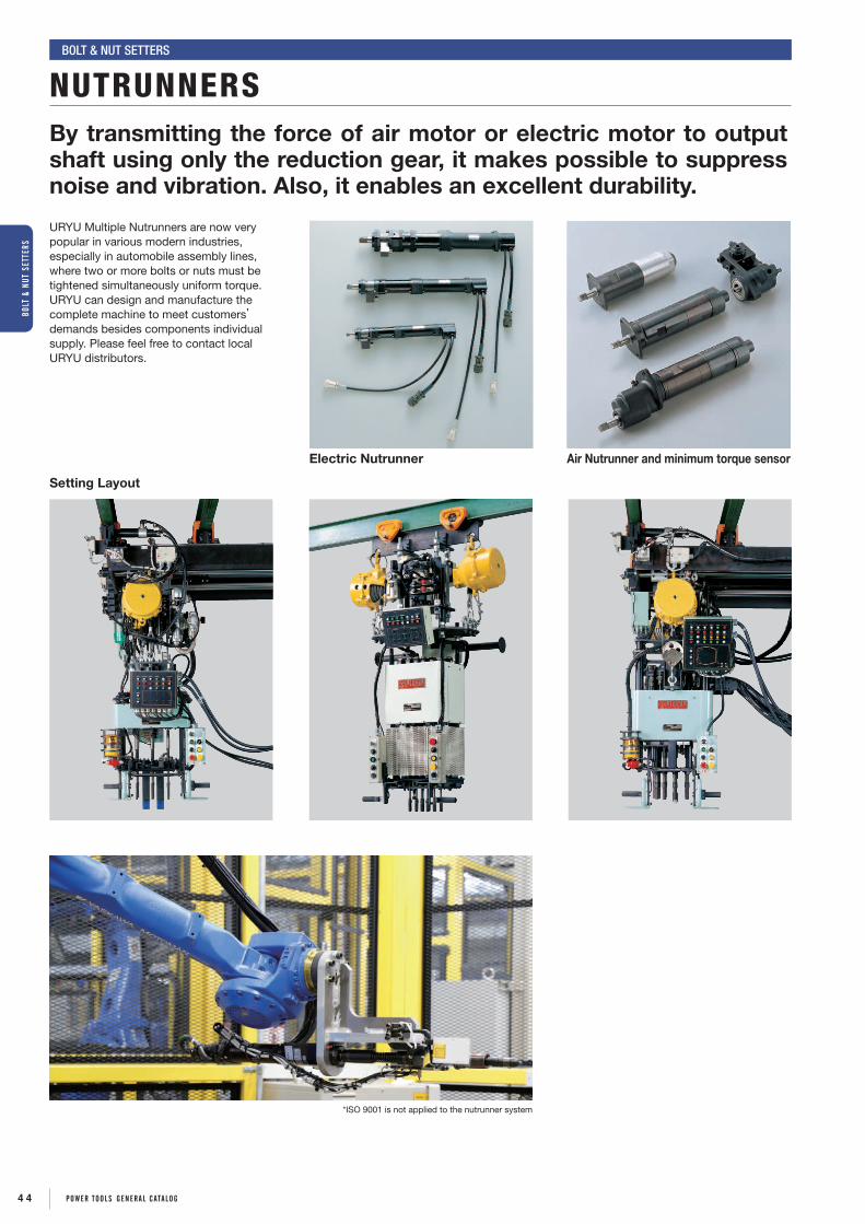
By transmitting the force of air motor or electric motor to output shaft using only the reduction gear, it makes possible to suppress noise and vibration. Also, it enables an excellent durability.
URYU Multiple Nutrunners are now very popular in various modern industries, especially in automobile assembly lines, where two or more bolts or nuts must be tightened simultaneously uniform torque.URYU can design and manufacture the complete machine to meet customers’ demands besides components individual supply. Please feel free to contact local URYU distributors.
Setting Layout
Air Nutrunner and minimum torque sensorElectric Nutrunner
NUTRUNNERSBolt & Nut SetterS
*ISO 9001 is not applied to the nutrunner system
4 4 POWER TOOLS gEnERAL cATALOg
BOLT
& n
UT S
ETTE
RS

TORQUE cOnTROL ScREWDRIVERS cUSHIOn cLUTcH TYPE ScREWDRIVERS
DIREcT DRIVE ScREWDRIVERS
IMPAcT ScREWDRIVERS
ScREWDRIVERS
4 5POWER TOOLS gEnERAL cATALOg

HeXAGoNAl SoCKet BItS
Group BitDimensions
PartNumberA B C D e
mm in mm in mm in mm in mm in
A 12 15/32 100 3 15/16 4.5 11/64 8 5/16 30 1 37/64 918-109-0
B
16 8/5 50 1 31/32 5.5 7/32 10 25/64 15 19/32 918-259-016 8/5 75 2 61/64 5.5 7/32 10 25/64 25 63/64 918-215-016 8/5 100 3 15/16 5.5 7/32 10 25/64 30 1 37/64 918-216-016 8/5 150 5 29/32 5.5 7/32 10 25/64 30 1 37/64 918-237-016 8/5 200 7 7/8 5.5 7/32 10 25/64 30 1 37/64 918-245-018 45/64 100 3 15/16 7 9/32 12 15/32 30 1 37/64 918-222-0
D 16 8/5 31 1 7/32 5.5 7/32 10 25/64 7 9/32 918-307-0
(+)PHIllIPS BItS
Group Bit(l) Part Number
mm In No.1 No.2 No.3
A 120 4 23/32 916-306-0 916-316-0 916-321-0
B
100 3 15/16 916-401-0 916-411-0 916-421-0
75 2 61/64 916-800-0 916-810-0 916-820-0
C 50 1 21/32 916-137-0 — —
D 30 1 37/64 916-501-0 916-511-0 916-521-0
L
3
2㎜
L1410
5㎜
L
16
5㎜
L
12
φ6
L9
6.35㎜
6.35㎜
6.35㎜
φ7
L19
L9
6.35㎜
L9
6.35㎜
φ3.5
φ3.5
φ4.5
φ4.5
φ4.5
φ4.5
φ4.5
5
5
5
4
5
5
5
14
φ4.8
L
3
2㎜
L1410
5㎜
L
16
5㎜
L
12
φ6
L9
6.35㎜
6.35㎜
6.35㎜
φ7
L19
L9
6.35㎜
L9
6.35㎜
φ3.5
φ3.5
φ4.5
φ4.5
φ4.5
φ4.5
φ4.5
5
5
5
4
5
5
5
14
φ4.8
L
3
2㎜
L1410
5㎜
L
16
5㎜
L
10.5
φ6
L9
6.35㎜
6.35㎜
6.35㎜
φ7
L19
L9
6.35㎜
L9
6.35㎜
φ3.5
φ3.5
φ4.5
φ4.5
φ4.5
φ4.5
φ4.5
5
5
5
4
5
5
5
14
φ4.8
L
3
2㎜
L1410
5㎜
L
16
5㎜
L
12
φ6
L9
6.35㎜
6.35㎜
6.35㎜
φ7
L19
L9
6.35㎜
L9
6.35㎜
φ3.5
φ3.5
φ4.5
φ4.5
φ4.5
φ4.5
φ4.5
5
5
5
4
5
5
5
14
φ4.8
L
3
2㎜
L1410
5㎜
L
16
5㎜
L
12
φ6
L9
6.35㎜
6.35㎜
6.35㎜
φ7
L19
L9
6.35㎜
L9
6.35㎜
φ3.5
φ3.5
φ4.5
φ4.5
φ4.5
φ4.5
φ4.5
5
5
5
4
5
5
5
14
φ4.8
5㎜B
14D
A
EC φ6
6.35㎜B
9D
A
EC φ7
6.35㎜B9
D
A
EC
φ3.55
φ4.55
φ4.55
5㎜B
14D
A
EC φ6
6.35㎜B
9D
A
EC φ7
6.35㎜B9
D
A
EC
φ3.55
φ4.55
φ4.55
5㎜B
14D
A
EC φ6
6.35㎜B
9D
A
EC φ7
6.35㎜B9
D
A
EC
φ3.55
φ4.55
φ4.55
Group of toolsA US-LT○○A/AL,US-3.5A,US-4,US-40,US-4PBB US-○○W/PW,US-450WB,US-LT○○B/BL/PB,US-5,US-50,US-5PBC US-LT10BD US-LT30B-○○C,US-LT40B-○○C,US-3.5ACB,US-4CA,US-5CA
Accessories
*Please ask your local URYU distributor for other bit size.
SELEcTIOn gUIDE Joint & Torque Curve Feature Clutch Type Model A B C
Free RunningHard Stop
Turns easily untilhead seats, theninstant resistance to torque build-up.
Oil-Pulse U & UX ◎ ◎ ○Oil-Pulse UAT,ULT & UL ◎ ◎ ◎Impact UW & US-○○W × ○ ×Torque Control US-LT series ○ ◎ ◎Direct Drive US-LD series ○ ○ ○Cushion Other US series ○ ○ ○
Soft Stop Turns easily untilhead seats, Gradualresistance as materialcompresses.
Oil-Pulse U & UX ◎ ◎ ○Oil-Pulse UAT,ULT & UL ◎ ◎ ○Impact UW & US-○○W × ○ ×Torque Control US-LT series ○ ◎ ◎Direct Drive US-LD series ○ ○ ○Cushion Other US series ○ ○ ○
Self-Tapping Thick Material
Constant heavy resistance until headseats. Then gradualor sudden build-up.
Oil-Pulse U & UX ◎ ○ ○Impact UW & US-○○W × ○ ×Torque Control US-LT series × × ×Direct Drive US-LD series ○ ○ ○Cushion Other US series ○ ○ ○
Self-Tapping Sheet Metal
Increasing resistancefollowed by easingthen sudden build-upas head seats.
Oil-Pulse U, UX & UL ◎ ◎ ◎Impact UW & US-○○W × ○ ×Torque Control US-LT series × × ×Direct Drive US-LD series ○ ○ ○Cushion Other US series ○ ○ ○
Self-Tapping Plastic
Constant heavyresistance until headseats. Then gradualor sudden build-up.
Oil-Pulse U, UX & UL ◎ ◎ ◎Impact UW & US-○○W × × ×Torque Control US-LT series ○ ◎ ◎Direct Drive US-LD series ○ ○ ○Cushion Other US series ○ ○ ○
Wood Screws Small starting resis-tance which increasesas screw is driven in.Heavier resistancewhen head seats.
Oil-Pulse U & UX ○ ○ ○Oil-Pulse UL ◎ ◎ ◎Impact UW & US-○○W × × ×Torque Control US-LT series × × ×Direct Drive US-LD series ○ ◎ ◎Cushion Other US series ○ ○ ○
Remarks : A=Ergonomics B=Job Efficiency C=Torque Accuracy Recommendation : ◎=Excellent ○=Good ×=Not Recommended
Turns
Torque
Turns
Turns
Torque
Torque
Turns
Torque
Turns
Torque
Turns
A
B
Torque
Turns
Torque
Turns
Turns
Torque
Torque
Turns
Torque
Turns
Torque
Turns
A
B
Torque
Turns
Torque
Turns
Turns
Torque
Torque
Turns
Torque
Turns
Torque
Turns
A
B
Torque
Turns
Torque
Turns
Turns
Torque
Torque
Turns
Torque
Turns
Torque
Turns
A
B
Torque
Turns
Torque
Turns
Turns
Torque
Torque
Turns
Torque
Turns
Torque
Turns
A
B
Torque
Turns
Torque
Turns
Turns
Torque
Torque
Turns
Torque
Turns
Torque
Turns
A
B
Torque
HeXAGoNAl WreNCH BIt Group B, C
BIt
L
13.5A8.5
6.35㎜23
φ7
Dimensions /Part Number
DimensionsPart
NumberA (l)mm in mm in
4 1/8 75 2 61/64 867-172-1
5 13/64 75 2 61/64 867-176-1
6 15/64 75 2 61/64 867-121-1
ScRE
WDR
IVER
S
4 6 POWER TOOLS gEnERAL cATALOg

Lever-Start TypePistol Type Angle-Head TypePush-Start Type
Fastening force of the screwdrivers changes in accordance to the fastening time and the bolt size.This table shows various common fastening torque. Please use this table as just guide line when selecting the model.
SELECTION CHARTSCreWDrIVerS
0.2 0.30.1 0.4 0.5 1.0Torque【Nm】
Torque【Nm】
Torque【Nm】
Torque【Nm】
2 4 53 10 20
2 31.0 4 5 10 20 40 5030 100 200
0.2 0.30.1 0.4 0.5 1.0 2 4 53 10 20
0.2 0.30.1 0.4 0.5 1.0 2 4 53 10 20
TORQUE-CONTROL TYPE
CUSHION CLUTCH TYPE
US-LT20A/B-26
US-3.5A US-3.5B US-3.5MA US-3.5PBUS-40
US-4 US-4PB US-4CAUS-5 US-5PB US-5CAUS-50
0.2 0.30.1 0.4 0.5 1.0Torque【Nm】
Torque【Nm】
Torque【Nm】
Torque【Nm】
2 4 53 10 20
2 31.0 4 5 10 20 40 5030 100 200
0.2 0.30.1 0.4 0.5 1.0 2 4 53 10 20
0.2 0.30.1 0.4 0.5 1.0 2 4 53 10 20
IMPACT TYPE
US-350W US-350PW US-45W US-450WB US-450PW
US-5W US-5PWUS-6W US-6PW
US-652PW
US-LT10BUS-LT20A/B-18
US-LT20A/B-10US-LT30A/B-23 US-LT30AL/BL-23 US-LT31PB-23
US-LT30A/B-17 US-LT30AL/BL-17 US-LT31PB-17 US-LT30B-17CUS-LT40A/B-21 US-LT40BL-21 US-LT41PB-21
US-LT30A/B-11 US-LT30AL/BL-11 US-LT31PB-11 US-LT30B-11CUS-LT40A/B-15 US-LT40AL/BL-15 US-LT41PB-15 US-LT40B-15C
US-LT50B-17 US-LT51PB-17US-LT40A/B-08 US-LT40BL-08 US-LT41PB-08 US-LT40B-08C US-LT40-08C(P)
US-LT31PB-05US-LT50B-08 US-LT51PB-08US-LT40B-05C US-LT40-05C(P)
US-LT60P-11US-LT60P-07US-LT40-03C(P)US-LT50B-05 US-LT51PB-05
US-LT60P-03
0.2 0.30.1 0.4 0.5 1.0Torque【Nm】
Torque【Nm】
Torque【Nm】
Torque【Nm】
2 4 53 10 20
2 31.0 4 5 10 20 40 5030 100 200
0.2 0.30.1 0.4 0.5 1.0 2 4 53 10 20
0.2 0.30.1 0.4 0.5 1.0 2 4 53 10 20
DIRECT DRIVE TYPE
US-3.5ACBUS-LD40P-21
US-LD40P-15US-LD40P-08
US-LD50P-17US-LD50P-08
US-LD50P-05
4 7POWER TOOLS gEnERAL cATALOg
ScREWDRIVERS

TORQUE CONTROL SCREWDRIVERSSCreWDrIVerS
US-LT10B
US-LT30B-11US-LT20A-10 US-LT30A-17
US-LT30AL-17
US-LT40A-08
US-LT40AL-15
US-LT50B-05 US-LT30BL-11
US-LT40BL-15 US-LT40BL-08
US-LT drivers enable you to set the shut-off torque. These small and light-weight screwdrivers contributes to reducing operators’ fatigue and to better productivity.
SPeCIFICAtIoNS Recommended Air Pressure : 0.5MPa (72psi)
ModelCapacity
(Screw Size) torque rangeFree
Speed(Approx.)
overalllength(about)
Weight less Bit
(about)
From Centerto outside
(about)
Air HoseSize
(inside Dia.)
AverageAir
Consumption Code
mm in Nm in-lbs rpm mm in kg lb mm in mm in m3/min ft3/minUS-LT10B 2.6 No.3 0.20-0.60 1.8-5.3 1000 191 7 33/64 0.29 0.63 12.0 31/64 6.35 1/4 0.15 5.2 47362US-LT20A-26 2.2 No.2 0.15-0.35 1.3-3.1 2600 180 7 3/32 0.34 0.68 13.0 33/64 6.35 1/4 0.16 5.6 47032US-LT20B-26 2.2 No.2 0.15-0.35 1.3-3.1 2600 180 7 3/32 0.34 0.68 13.0 33/64 6.35 1/4 0.16 5.6 47042US-LT20A-18 2.6 No.3 0.25-0.70 2.2-6.2 1800 180 7 3/32 0.34 0.68 13.0 33/64 6.35 1/4 0.16 5.6 47052US-LT20B-18 2.6 No.3 0.25-0.70 2.2-6.2 1800 180 7 3/32 0.34 0.68 13.0 33/64 6.35 1/4 0.16 5.6 47062US-LT20A-10 3 No.5 0.35-1.10 3.1-9.68 1000 180 7 3/32 0.34 0.68 13.0 33/64 6.35 1/4 0.16 5.6 47072US-LT20B-10 3 No.5 0.35-1.10 3.1-9.68 1000 180 7 3/32 0.34 0.68 13.0 33/64 6.35 1/4 0.16 5.6 47082US-LT30A-23 3 No.5 0.40-1.00 3.5-8.8 2300 187 7 23/64 0.43 0.94 15.5 39/64 6.35 1/4 0.20 7.0 47122US-LT30B-23 3 No.5 0.40-1.00 3.5-8.8 2300 187 7 23/64 0.43 0.94 15.5 39/64 6.35 1/4 0.20 7.0 47132US-LT30A-17 3.5 No.6 0.70-1.50 6.2-13.2 1700 187 7 23/64 0.43 0.94 15.5 39/64 6.35 1/4 0.20 7.0 47142US-LT30B-17 3.5 No.6 0.70-1.50 6.2-13.2 1700 187 7 23/64 0.43 0.94 15.5 39/64 6.35 1/4 0.20 7.0 47152US-LT30A-11 4 No.8 1.10-2.10 9.7-18.5 1100 187 7 23/64 0.43 0.94 15.5 39/64 6.35 1/4 0.20 7.0 47162US-LT30B-11 4 No.8 1.10-2.10 9.7-18.5 1100 187 7 23/64 0.43 0.94 15.5 39/64 6.35 1/4 0.20 7.0 47172US-LT40A-21 4 No.8 1.00-1.70 6.2-15.0 2100 209 8 15/64 0.65 1.43 16.5 41/64 6.35 1/4 0.30 10.5 47222US-LT40B-21 4 No.8 1.00-1.70 6.2-15.0 2100 209 8 15/64 0.65 1.43 16.5 41/64 6.35 1/4 0.30 10.5 47232US-LT40A-15 4 No.8 1.00-2.20 6.2-19.4 1500 209 8 15/64 0.65 1.43 16.5 41/64 6.35 1/4 0.30 10.5 47242US-LT40B-15 4 No.8 1.00-2.20 6.2-19.4 1500 209 8 15/64 0.65 1.43 16.5 41/64 6.35 1/4 0.30 10.5 47252US-LT40A-08 5 No.10 1.60-4.00 14.1-35.2 800 209 8 15/64 0.65 1.43 16.5 41/64 6.35 1/4 0.30 10.5 47262US-LT40B-08 5 No.10 1.60-4.00 14.1-35.2 800 209 8 15/64 0.65 1.43 16.5 41/64 6.35 1/4 0.30 10.5 47272US-LT50B-17 4-5 No.8-No.10 1.50-2.60 9.7-23.0 1700 240 9 29/64 1.00 2.20 19.5 49/64 9.50 3/8 0.50 17.5 44422US-LT50B-08 5-6 No.10-1/4 3.00-5.50 26.4-48.4 800 240 9 29/64 1.00 2.20 19.5 49/64 9.50 3/8 0.50 17.5 44432US-LT50B-05 5-6 No.10-1/4 5.00-10.5 44.0-92.4 480 240 9 29/64 1.00 2.20 19.5 49/64 9.50 3/8 0.50 17.5 44442US-LT30AL-23 3 No.5 0.40-1.00 3.52-8.8 2300 229 8 15/64 0.53 1.16 15.0 19/32 6.35 1/4 0.20 5.2 46622US-LT30BL-23 3 No.5 0.40-1.00 3.52-8.8 2300 229 8 15/64 0.53 1.16 15.0 19/32 6.35 1/4 0.20 5.2 46632US-LT30AL-17 3.5 No.6 0.70-1.50 6.2-13.2 1700 229 8 15/64 0.53 1.16 15.0 19/32 6.35 1/4 0.20 5.2 46642US-LT30BL-17 3.5 No.6 0.70-1.50 6.2-13.2 1700 229 8 15/64 0.53 1.16 15.0 19/32 6.35 1/4 0.20 5.2 46652US-LT30AL-11 4 No.6 1.10-2.10 9.7-18.5 1100 229 8 15/64 0.53 1.16 15.0 19/32 6.35 1/4 0.20 5.2 46662US-LT30BL-11 4 No.6 1.10-2.10 9.7-18.5 1100 229 8 15/64 0.53 1.16 15.0 19/32 6.35 1/4 0.20 5.2 46672US-LT40BL-21 4 No.8 1.00-1.70 8.8-15.0 2100 249 9 25/32 0.70 1.54 17.0 21/32 6.35 1/4 0.30 5.6 46732US-LT40AL-15 4 No.8 1.00-2.20 8.8-19.4 1500 249 9 25/32 0.70 1.54 17.0 21/32 6.35 1/4 0.30 5.6 46742US-LT40BL-15 4 No.8 1.00-2.20 8.8-19.4 1500 249 9 25/32 0.70 1.54 17.0 21/32 6.35 1/4 0.30 5.6 46752US-LT40BL-08 5 No.10 1.60-4.00 14.1-35.2 800 249 9 25/32 0.70 1.54 17.0 21/32 6.35 1/4 0.30 5.6 46772
Air Inlet Size : NPT1/8" for US-LT10/20 series NPT1/4" for US-LT30/40/50 series
Hex. Size of Bit : 5mm (13/64") for A-Type 6.35mm (1/4") for B-Type
4 8 POWER TOOLS gEnERAL cATALOg
ScRE
WDR
IVER
S

US-LT31PB-05
US-LT51PB-05
US-LT60P-03
US-LT40B-05C
TORQUE CONTROL SCREWDRIVERSSCreWDrIVerS
US-LT20-40 Series Optional PartsSilencer Assembly
Detachable Silencer Assembly to minimize noise can be attached for more comfortable working environment.
US-LT20 Series 455-088-2US-LT30 Series 408-088-2US-LT40 Series 496-088-1
Handle Jacket
Rubber Handle Jacket is available as an optional accessory for operator’s comfort.
US-LT20 470-083-9US-LT30 471-083-7US-LT40 496-083-0
OPTIOn
SPeCIFICAtIoNS Recommended Air Pressure : 0.5MPa (72psi)
ModelCapacity
(Screw Size) torque rangeFree
Speed(Approx.)
overalllength(about)
Weight less Bit
(about)
From Centerto outside
(about)
Air HoseSize
(inside Dia.)
AverageAir
Consumption Code
mm in Nm in-lbs rpm mm in kg lb mm in mm in m3/min ft3/minUS-LT31PB-23 2.6 No.3 0.40-1.00 3.5-8.8 2300 170 7 1/64 0.71 1.56 16.0 39/64 6.35 1/4 0.20 7.0 44222US-LT31PB-17 2.2 No.2 0.70-1.50 6.2-13.2 1700 170 7 1/64 0.71 1.56 16.0 39/64 6.35 1/4 0.20 7.0 44232US-LT31PB-11 2.6 No.3 1.10-2.10 9.7-18.5 1100 170 7 1/64 0.71 1.56 16.0 39/64 6.35 1/4 0.20 7.0 44242US-LT31PB-05 3 No.5 2.40-5.00 21.1-44.0 500 189 8 3/16 0.85 1.87 16.0 39/64 6.35 1/4 0.20 7.0 44252US-LT41PB-21 3 No.5 1.00-1.70 8.8-15.0 2500 175 7 23/32 0.87 1.91 17.0 41/64 6.35 1/4 0.30 10.5 44332US-LT41PB-15 3.5 No.6 1.00-2.20 8.8-19.4 1500 175 7 23/32 0.87 1.91 17.0 41/64 6.35 1/4 0.30 10.5 44342US-LT41PB-08 4 No.8 1.60-4.00 14.1-35.2 800 175 7 23/32 0.87 1.91 17.0 41/64 6.35 1/4 0.30 10.5 44352US-LT51PB-17 4 No.8 1.50-2.60 13.2-22.9 1700 198 8 35/64 1.20 2.64 20.0 49/64 9.50 3/8 0.50 17.5 44562US-LT51PB-08 4 No.8 3.00-5.50 26.4-48.4 800 198 8 35/64 1.20 2.64 20.0 49/64 9.50 3/8 0.50 17.5 44572US-LT51PB-05 5 No.10 5.00-10.5 44.0-92.4 480 198 8 35/64 1.20 2.64 20.0 49/64 9.50 3/8 0.50 17.5 44582US-LT60P-11 4-5 No.8-No.10 4.00-7.00 35.2-61.6 1100 230 9 1/16 1.70 3.74 22.0 57/64 9.50 3/8 0.60 21.0 49902US-LT60P-07 5-6 No.10-1/4 4.00-10.0 35.2-88.0 650 230 9 1/16 1.70 3.74 22.0 57/64 9.50 3/8 0.60 21.0 49932US-LT60P-03 5-6 No.10-1/4 7.00-20.0 61.6-176 320 230 9 1/16 1.70 3.74 22.0 57/64 9.50 3/8 0.60 21.0 49962
Air Inlet Size : NPT1/4" Hex. Size of Bit : 6.35mm (1/4")
SPeCIFICAtIoNS Recommended Air Pressure : 0.5MPa (72psi)
ModelCapacity
(Screw Size) torque rangeFree
Speed(Approx.)
overalllength(about)
Weight less Bit
(about)
From Centerto outside
(about)
Air HoseSize
(inside Dia.)
AverageAir
Consumption Code
mm in Nm in-lbs rpm mm in kg lb mm in mm in m3/min ft3/minUS-LT30B-17C 2.6 No.3 0.70-1.50 6.2-13.2 1700 295 10 3/4 0.70 1.54 36.0 1 27/64 6.35 1/4 0.20 7.0 46932US-LT30B-11C 2.2 No.2 1.10-2.10 9.7-18.5 1100 295 10 3/4 0.70 1.54 36.0 1 27/64 6.35 1/4 0.20 7.0 46952US-LT40B-15C 2.6 No.3 1.00-2.20 8.8-19.4 1500 314 12 25/32 0.90 1.98 36.0 1 27/64 6.35 1/4 0.30 10.5 46152US-LT40B-08C 3 No.5 1.60-4.00 14.1-35.2 800 314 12 25/32 0.90 1.98 36.0 1 27/64 6.35 1/4 0.30 10.5 46162US-LT40B-05C 3 No.5 2.30-5.70 20.2-50.2 500 325 13 7/32 0.95 2.09 38.5 1 33/64 6.35 1/4 0.30 10.5 46132US-LT40-08C(P) 3.5 No.6 1.60-4.00 14.1-35.2 800 314 12 25/32 0.90 1.98 32.0 1 17/64 6.35 1/4 0.30 10.5 46192US-LT40-05C(P) 4 No.8 2.30-5.70 20.2-50.2 500 325 13 7/32 0.95 2.09 35.5 1 25/64 6.35 1/4 0.30 10.5 46182US-LT40-03C(P) 4 No.8 5.00-10.0 44-88 300 359 14 11/64 1.10 2.42 35.5 1 25/64 6.35 1/4 0.30 10.5 46172
Air Inlet Size : NPT1/4" Hex. Size of Bit : 6.35mm (1/4") for B-Type Sq Size of Anvil : 6.35mm (1/4") for US-LT40 Series
US-LT60P(P) SeriesOptional 9.5mm (3/8") Sq. Drive Anvil is alternatively available. Suffix each model name with (P) as US-LT60P-03(P) or -07(P) when ordering.
Torque reaction bar should be attached for solid support to absorb the reaction when the tool comes to stall.
US-LT40-03C(P)
4 9POWER TOOLS gEnERAL cATALOg
ScREWDRIVERS

US-4
US-40
Adjusting Nut
Adjusting Spring
The output torque can be adjusted by turning the adjusting nut to control spring compression or by changing the suitable spring.
FEATURES
CUSHION CLUTCH TYPE SCREWDRIVERSSCreWDrIVerS
US-5PB
US-3.5ACB
US-5CA
SPeCIFICAtIoNS Recommended Air Pressure : 0.4MPa (57psi)
ModelCapacity
(Screw Size)Free
Speed(Approx.)
overalllength
(about)
Weight less Socket or Bit
(about)
From Centerto outside
(about)
Hex.Size of
Bit
Air HoseSize
AverageAir
Consumption Code
mm in rpm mm in kg lb mm in mm in mm in m3/min ft3/minUS-3.5A 4 No.8 2000 196 7 31/64 0.60 1.39 17.0 43/64 5.00 13/64 6.35 1/4 0.20 7.0 41012US-3.5B 4 No.8 2000 214 8 27/54 0.63 1.39 17.0 43/64 6.35 1/4 6.35 1/4 0.20 7.0 41412US-4 4 No.8 1400 236 7 3/32 0.95 2.09 20.0 25/32 5.00 13/64 6.35 1/4 0.20 7.0 41812US-5 5 No.10 1400 236 7 3/32 1.10 2.42 21.0 53/64 6.35 1/4 6.35 1/4 0.20 7.0 43012
Air Inlet Size : NPT1/4"
SPeCIFICAtIoNS Recommended Air Pressure : 0.4MPa (57psi)
ModelCapacity
(Screw Size)Free
Speed(Approx.)
overalllength
(about)
Weight less Socket or Bit
(about)
From Centerto outside
(about)
Hex.Size of
Bit
Air HoseSize
AverageAir
Consumption Code
mm in rpm mm in kg lb mm in mm in mm in m3/min ft3/minUS-3.5MA 4 No.8 2000 198 7 3/32 0.65 0.68 17.0 43/64 6.35 1/4 6.35 1/4 0.20 7.0 41112
Air Inlet Size : NPT1/4"
SPeCIFICAtIoNS Recommended Air Pressure : 0.4MPa (57psi)
ModelCapacity
(Screw Size)Free
Speed(Approx.)
overalllength
(about)
Weight less Socket or Bit
(about)
From Centerto outside
(about)
Hex.Size of
Bit
Air HoseSize
AverageAir
Consumption Code
mm in rpm mm in kg lb mm in mm in mm in m3/min ft3/minUS-40 4 No.8 2200 225 8 55/64 0.56 1.23 17.0 43/64 5.00 13/64 6.35 1/4 0.20 7.0 48702US-50 5 No.10 1200 245 9 41/64 0.90 1.98 18.0 45/64 6.35 1/4 6.35 1/4 0.30 10.7 49612
Air Inlet Size : NPT1/4"
SPeCIFICAtIoNS Recommended Air Pressure : 0.4MPa (57psi)
ModelCapacity
(Screw Size)Free
Speed(Approx.)
overalllength
(about)
Weight less Bit
(about)
From Centerto outside
(about)
Air InletSize
Hex.Size of
Bit
AverageAir
Consumption Code
mm in rpm mm in kg lb mm in in mm in m3/min ft3/minUS-3.5PB 4 No.8 2000 200 7 7/8 0.75 1.65 17.0 43/64 NPt1/4 6.35 1/4 0.20 7.0 41712US-4PB 4 No.8 1400 223 8 25/32 1.15 2.53 20.0 49/64 NPt1/4 5.00 13/64 0.20 7.0 42012US-5PB 5 No.8 1400 242 9 17/32 1.30 2.86 21.0 33/64 NPt1/4 6.35 1/4 0.20 7.0 43212
* US-3.5ACB 4 No.8 2000 200 7 7/8 0.65 1.43 10.0 25/64 NPt1/4 6.35 1/4 0.20 7.0 41242US-4CA 4 No.8 1400 225 8 7/8 1.10 2.24 12.0 29/64 NPt1/4 6.35 1/4 0.30 10.7 42212US-5CA 5 No.10 500 256 10 5/64 1.40 3.08 12.0 29/64 NPt1/4 6.35 1/4 0.30 10.7 43412
*US-3.5ACB is not the cushion clutch type but the direct drive type. Air Hose Size (Inside Diameter) : 6.35mm (1/4")
Bit(Automaticallymagnetized)
Magnetic Bar
The standard bit contacts the bult-in Magnetic Bar to be magnetized and holds the screw.
Cutaway view of Magnet type head for US-3.5MA Head Sizes
ModelC H
mm in mm in
US-3.5ACB 10.0 25/64 36.5 1 33/64
US-4CA 12.0 15/32 45.0 1 25/32
US-5CA 12.0 15/32 45.0 1 25/32
C
H
5 0 POWER TOOLS gEnERAL cATALOg
ScRE
WDR
IVER
S

DIRECT DRIVE SCREWDRIVERSSCreWDrIVerS
US-LD40P-21
US-LD50P-17 Down for reversing
Down for forwarding
Up for forwarding
By replacing Reverse Lever, Operator can use either left or right hand.
Up for reversing
SPeCIFICAtIoNS Recommended Air Pressure : 0.5MPa (72psi)
ModelCapacity
(Screw Size)
torque range FreeSpeed(about)
overalllength(about)
Weight lessBit
(about)
From Centerto outside
(about)
AverageAir
Consumption CodeSoft Joint Hard Joint
mm in Nm ft-lbs Nm ft-lbs rpm mm in kg lb mm in m3/min ft3/min
US-LD40P-21 4 No.8 2.0 1.5 2.8 2.1 2500 130 5 1/14 0.7 1.54 17.0 43/64 0.40 14.0 42522
US-LD40P-15 4 No.8 3.0 2.2 3.2 2.4 1700 130 5 1/14 0.7 1.54 17.0 43/64 0.40 14.0 42532
US-LD40P-08 5 No.10 4.8 3.6 5.7 4.2 940 130 5 1/14 0.7 1.54 17.0 43/64 0.40 14.0 42542
US-LD50P-17 4 No.8 3.5 2.6 5.9 4.4 1900 150 5 29/32 0.9 2.01 20.0 49/64 0.50 17.5 42622
US-LD50P-08 5 No.10 6.5 4.8 7.8 5.8 900 153 6 1/32 0.9 2.01 20.0 49/64 0.50 17.5 42632
US-LD50P-05 5 No.10 10.0 7.4 11.2 8.3 500 153 6 1/32 0.9 2.01 20.0 49/64 0.50 17.5 42642
Air Inlet Size : NPT1/4" Air Hose Size : 6.35mm (1/4") Hex.Size of Bit : 6.35mm (1/4")
5 1POWER TOOLS gEnERAL cATALOg
ScREWDRIVERS

IMPACT SCREWDRIVERSSCreWDrIVerS
US-350PW
US-450PW US-5PW
US-6PW US-652PW
US-45W
US-350W
Small, light-weight, and high power. Operators’ fatigue can be reduced thanks to discontinuous drive which has less torque reaction.
US-450WB
US-5W
US-6W
SPeCIFICAtIoNS (StrAIGHt tYPe)
ModelCapacity
(Screw Size)Free
Speed(Approx.)
overalllength
(about)
Weight less Bit
(about)
From Centerto outside
(about)
Hex.Size of
Bit
Air HoseSize
(inside Dia)
AverageAir
Consumption
recommendedAir
Pressure Code
mm in rpm mm in kg lb mm in mm in mm in m3/min ft3/min Mpa psi
US-350W 4 No.8 14000 168 6 5/8 0.40 0.88 17.0 43/64 6.35 1/4 6.35 1/4 0.20 7.0 0.4 57 40952
US-450WB 5 No.10 11000 161 6 5/16 0.55 1.21 18.5 47/64 6.35 1/4 6.35 1/4 0.20 7.0 0.4 57 43832
US-45W 5 No.10 12000 183 7 13/64 0.50 1.10 17.0 43/64 6.35 1/4 6.35 1/4 0.20 7.0 0.4 57 44612
US-5W 5 No.10 9500 198 7 51/64 0.80 1.60 20.0 27/32 6.35 1/4 6.35 1/4 0.20 7.0 0.4 57 43912
US-6W 6 1/4 9500 187 7 23/64 0.80 1.76 22.5 57/64 6.35 1/4 6.35 1/4 0.30 10.5 0.4 57 47612
Air Inlet Size : NPT1/4"
SPeCIFICAtIoNS (PIStol tYPe)
ModelCapacity
(Screw Size)Free
Speed(Approx.)
overalllength
(about)
Weight less Bit
(about)
From Centerto outside
(about)
Hex.Size of
Bit
Air HoseSize
(inside Dia)
AverageAir
Consumption
recommendedAir
Pressure Code
mm in rpm mm in kg lb mm in mm in mm in m3/min ft3/min Mpa psi
US-350PW 4 No.8 15000 121 4 49/64 0.53 1.16 17.0 43/64 6.35 1/4 6.35 1/4 0.20 7.0 0.4 57 40972
US-450PW 5 No.10 14000 151 5 15/16 0.75 1.65 17.0 43/64 6.35 1/4 6.35 1/4 0.20 7.0 0.4 57 45302
US-5PW 5 No.10 9500 168 6 5/8 0.95 2.10 20.0 25/32 6.35 1/4 6.35 1/4 0.30 10.5 0.4 57 44012
US-6PW 6 1/4 9500 170 6 11/16 1.00 2.20 23.0 57/64 6.35 1/4 6.35 1/4 0.30 10.5 0.4 57 47662
US-652PW 6 1/4 9000 155 6 7/64 0.85 1.87 23.0 15/16 6.35 1/4 6.35 1/4 0.35 12.4 0.5 72 48082
Air Inlet Size : NPT1/4"
5 2 POWER TOOLS gEnERAL cATALOg
ScRE
WDR
IVER
S

The "Line Reel" air hose balancer, without any hampering chain or rope to balance the tool, contributes to keep the work bench and work area uncluttered for safer operation, higher productivity, less operator's fatigue and longer tool life.
AIR HOSE BALANCERSCreWDrIVerS
AuxiliarySuspension
Rotary Joint Shaft
StopperLoosen the two locking screws to change the positions for stroke adjustment.
Locking SpringPush to release the Adjustment Dial for anti-clockwise turn.
Adjustment Dial Turnclockwise for heavier load and counter-clockwise for lighter load.
Silencer AssemblyDetachable Silencer Assembly (Option) to minimize noise can be attached for more comfortable working environment.
Handle JacketRubber Handle Jacket is available as an optional accessory for operator's comfort.
Main Suspension
125459/64"
563 /64"
341/64"
441 /64"
92.5
152
118
455-088-2 US-LT20 Series408-088-2 US-LT30 Series496-088-1 US-LT40 Series
US-LT50 Series
470-083-9 US-LT20 Series471-083-7 US-LT30 Series496-083-0 US-LT40 Series
SPeCIFICAtIoNS
ModelMax Suspending
CapacityAir Hose Size
I.D. x o.D. x lengthWeight(about)
MaxStroke
MaxAir Pressure Code
kg lb mm in kg lb mm in Mpa psi
LR-09(B-90) 1.4 3.08 5 × 8.5 × 900 13/64 × 21/64 × 35 7/16 0.85 1.87 700 27 9/16 1 142 99022
LR-09(B-200) 1.4 3.08 5 × 8.5 × 2000 13/64 × 21/64 × 78 47/64 0.9 1.98 700 27 9/16 1 142 99082
5 3POWER TOOLS gEnERAL cATALOg
ScREWDRIVERS

ABRASIVE TOOLS
GR INDERS
SANDERS
POLISHERS
5 4 POWER TOOLS GENERAL cATALOG

SPECIFICATIONS Recommended Air Pressure : 0.6MPa (85psi)
Model
ColletChuckSize
Max.FreeSpeed(about)
RatedHorsePower
OverallLength(about)
Weightless wheel
(about)
Air InletThread
(Pipe Tap)
Air HoseSize
AverageAir
Consumption Code
mm in rpm w mm in kg lb in mm in m3/min ft3/min
UG-20A-120 6 1/4 12000 113 131 5 3/16 0.50 1.10 NPT1/4 9.5 3/8 0.3 10.7 51752
UG-20A-200 6 1/4 20000 113 131 5 3/16 0.50 1.10 NPT1/4 9.5 3/8 0.3 10.7 51732
UG-50S-200A 6 1/4 20000 195 195 7 45/64 0.90 1.98 NPT1/4 9.5 3/8 0.4 14.0 50862
* Please never mount Grinding Wheel whose diameter is 50mm and larger.
SPECIFICATIONS Recommended Air Pressure : 0.6MPa (85psi)
Model
ColletChuckSize
Max.FreeSpeed(about)
RatedHorsePower
OverallLength(about)
Weightless wheel
(about)
Air InletThread
(Pipe Tap)
Air HoseSize
AverageAir
ConsumptionCode
mm in rpm w mm in kg lb in mm in m3/min ft3/min 6mm 1/4"UG-25NSA 6 1/4 23500 210 145 5 23/32 0.56 1.23 NPT1/4 9.5 3/8 0.3 10.7 50162 50152UG-38NS 6 1/4 25000 315 174 6 27/32 0.60 1.32 NPT1/4 9.5 3/8 0.3 10.7 50612 50662UG-38NSA 6 1/4 22000 315 174 6 27/32 0.65 1.43 NPT1/4 9.5 3/8 0.3 10.7 50702 -UG-38NSL 6 1/4 21000 315 330 12 63/64 0.95 2.09 NPT1/4 9.5 3/8 0.3 10.7 50762 50782
* Please never mount Grinding Wheel whose diameter is 50mm and larger. Chuck Nut Chuck
47mm (1 55/64)
Chuck Assembly 6mm 923-512-0Chuck Assembly 3mm 923-510-0Chuck Assembly 1/4" 923-516-0
UG-38N Series Chuck Assembly(Chuck+Chuck Nut)
COLLET CHUCKS
Chuck 6mm 923-003-0Chuck 3mm 923-001-0Chuck 1/4" 923-006-0
UG-25N Series30mm (1 3/16)
Collet Chuck Spindle
DIE GRINDERSABRASIVE TOOLS
SPECIFICATIONS Recommended Air Pressure : 0.6MPa (85psi)
Model
ColletChuckSize
Max.FreeSpeed(about)
RatedHorsePower
OverallLength(about)
Weightless wheel
(about)
Air InletThread
(Pipe Tap)
Air HoseSize
AverageAir
ConsumptionCode
mm in rpm w mm in kg lb in mm in m3/min ft3/min 6mm 1/4"UG-25NA 6 1/4 23500 210 153 6 1/32 0.53 1.17 NPT1/4 9.5 3/8 0.3 10.7 50062 50072G-38EB 6 1/4 20000 315 165 6 1/2 0.65 1.43 NPT1/4 9.5 3/8 0.4 14.0 50442 50452UG-38N 6 1/4 25000 315 164 6 15/32 0.57 1.25 NPT1/4 9.5 3/8 0.3 10.7 50512 50412UG-38NA 6 1/4 22000 315 165 6 1/2 0.65 1.43 NPT1/4 9.5 3/8 0.4 14.0 50562 50552UG-38NL 6 1/4 21000 315 316 12 7/16 0.92 2.02 NPT1/4 9.5 3/8 0.3 10.7 50712 50722UG-50S-200 6 1/4 23000 195 198 7 51/64 0.60 1.32 NPT1/4 9.5 3/8 0.4 14.0 50842 50852
* Please never mount Grinding Wheel whose diameter is 50mm and larger.
Self-Locking Lever attachmentTo prevent accidental start of motor.
COLLET CHUCKSG-38EB & UG-50S-200
42mm (1 21/32)
Chuck Nut Chuck3/8"-24
923-534-0 3mm923-535-0 6mm923-536-0 1/4"
UG-25NA
UG-38NAUG-38NL
UG-38N
UG-38NSA UG-38NS
UMG-450UG-45H
SPECIFICATIONS Recommended Air Pressure : 0.6MPa (85psi)
Model
ColletChuckSize
Max.FreeSpeed(about)
RatedHorsePower
OverallLength(about)
Weightless wheel
(about)
Air InletThread
(Pipe Tap)
Air HoseSize
AverageAir
Consumption Code
mm in rpm w mm in kg lb in mm in m3/min ft3/min
UMG-450 3 No.5 45000 37 145 5 45/64 0.19 0.42 NPT1/4 4.8 3/16 0.2 7.0 58712
UG-45H 6 1/4 18000 375 196 7 23/62 0.80 1.76 NPT1/4 9.5 3/8 0.6 22.0 51632
* Please never mount Grinding Wheel whose diameter is 50mm and larger.
UG-20A-200
C
H
C
H
ModelC H
mm in mm in
UG-20A-120 14.5 37/64 80.0 3 5/32
UG-20A-200 14.5 37/64 80.0 3 5/32
UG-50S-200A 19.5 49/64 87.0 3 27/64
923-170-0 6mm923-171-0 1/4"923-172-0 8mm
COLLET CHUCKSUG-45H
Fasten the collet chuck firmly to avoid loosening of the cutting tool.
5 5POWER TOOLS GENERAL cATALOG
ABRASIVE TOOLS

AG-100S
GRINDERSABRASIVE TOOLS
Collet chucks of 6mm and 1/4" capacity are available as optional accessories for mandrel mounted abrasives, cutters and files.
57㎜
Collet NutCollet Chuck
3/8"-24
6mm 1/4"UNF3/8-24 923-530-0 923-532-0W3/8-16 923-523-0 923-526-0
SPECIFICATIONS Recommended Air Pressure : 0.6MPa (85psi)
Type Model ThrottleHandle
Capacity(Wheel Size)
Max.FreeSpeed(about)
RatedHorsePower
OverallLength(about)
Weightless wheel
(about)
Air InletThread
(Pipe Tap)
Air HoseSize
AverageAir
Consumption Code
mm in rpm w mm in kg lb in mm in m3/min ft3/min
UG-65E Sleeve 63.5 2 1/2 14600 412 242 9 27/32 1.25 2.75 NPT1/4 9.5 3/8 0.6 22 50912
Standard UG-65ER Self-closing 63.5 2 1/2 14600 412 271 10 43/64 1.50 3.30 NPT1/4 9.5 3/8 0.6 22 50902
UG-65EL Lever 63.5 2 1/2 14600 412 272 10 23/32 1.40 3.08 NPT1/4 9.5 3/8 0.6 22 50922
RearExhaust
UG-65EB Sleeve 63.5 2 1/2 *14600 412 242 9 27/32 1.25 2.75 NPT1/4 9.5 3/8 0.6 22 50962
UG-65EBR Self-closing 63.5 2 1/2 *14600 412 271 10 43/64 1.50 3.30 NPT1/4 9.5 3/8 0.6 22 50972
UG-65EBL Lever 63.5 2 1/2 *14600 412 272 10 23/32 1.40 3.08 NPT1/4 9.5 3/8 0.6 22 50982
UG-650E Sleeve 63.5 2 1/2 14600 412 390 15 23/64 1.72 3.78 NPT1/4 9.5 3/8 0.6 22 50942
Extended UG-650ER Self-closing 63.5 2 1/2 14600 412 419 16 1/2 1.97 4.33 NPT1/4 9.5 3/8 0.6 22 50932
UG-650EL Lever 63.5 2 1/2 14600 412 420 16 17/32 1.55 3.41 NPT1/4 9.5 3/8 0.6 22 51132
* Speed without silencer
UG-65EUG-650E
USG-4S AG-50L
SPECIFICATIONS Recommended Air Pressure : 0.6MPa (85psi)
ModelCapacity
(Wheel Size)
Max.FreeSpeed(about)
RatedHorsePower
OverallLength(about)
Overall Height(about)
Weightless wheel
(about)
Typeof
Spindle
Air InletThread
(Pipe Tap)
Air HoseSize
AverageAir
Consumption Code
mm in rpm w mm in mm in kg lb in mm in m3/min ft3/min
AG-50(OUT) 50 2 15000 337 147 5 25/32 54 2 1/2 0.63 1.40 OUT NPT1/4 9.5 3/8 0.45 16.0 53622
AG-50L(OUT) 50 2 15000 337 140 5 34/64 54 2 1/2 0.63 1.40 OUT NPT1/4 9.5 3/8 0.45 16.0 53632
AG-100(IN) 100 4 13500 315 175 6 57/64 68 2 43/64 0.95 2.10 IN NPT1/4 9.5 3/8 0.50 18.0 53922
AG-100L(IN) 100 4 13500 315 179 7 3/64 68 2 43/64 1.05 2.30 IN NPT1/4 9.5 3/8 0.50 18.0 53932
AG-100(OUT) 100 4 13500 315 175 6 57/64 68 2 43/64 0.95 2.10 OUT NPT1/4 9.5 3/8 0.50 18.0 53962
AG-100L(OUT) 100 4 13500 315 179 7 3/64 68 2 43/64 1.05 2.30 OUT NPT1/4 9.5 3/8 0.50 18.0 53972
AG-100S(IN) 100 4 13500 315 175 6 57/64 68 2 43/64 1.00 2.20 IN NPT1/4 9.5 3/8 0.50 18.0 53902
AG-100SL(IN) 100 4 13500 315 179 7 3/64 68 2 43/64 1.10 2.40 IN NPT1/4 9.5 3/8 0.50 18.0 53912
AG-100S(OUT) 100 4 13500 315 179 7 3/64 68 2 43/64 1.00 2.20 OUT NPT1/4 9.5 3/8 0.50 18.0 53942
AG-100SL(OUT) 100 4 13500 315 179 7 3/64 68 2 43/64 1.10 2.40 OUT NPT1/4 9.5 3/8 0.50 18.0 53952
USG-4S 100 4 13500 450 236 9 19/64 94 3 45/64 1.65 3.60 IN NPT1/4 9.5 3/8 0.60 22.0 55462
USG-7S 180 7 7600 962 296 11 21/32 120 4 47/54 3.00 6.60 IN NPT3/8 12.7 1/2 1.30 46.0 57312
USG-L180D 180 7 7600 888 267 9 1/2 92 3 5/8 2.70 5.90 IN NPT3/8 12.7 1/2 1.00 36.0 54452
WHEEL SIZE
H T
Model Thickness HeightAG-50 Series 3-5mm 9mmAG-100 Series 4-6mm 10mmUSG-4S 4-6mm 10mmUSG-7S 6-8mm 13mmUSG-L180D 6-8mm 13mm
Wrench
Retaining NutAllen Head ScrewAllen Wrench
Grinding Wheel or Rubber Pad forsanding.
Backing Flange
Pin Head Spanner
Retaining NutAllen Wrench
Grinding Wheel or Rubber Pad forsanding.
Backing Flange
Setting Bolt
Wrench
"OUT" type 3/8"-24 Spindle with large FLANGE
"IN" type URYU special Spindle with small FLANGE
5 6 POWER TOOLS GENERAL cATALOG
ABRA
SIVE
TOO
LS

VERTICAL GRINDERSABRASIVE TOOLS
100mm(4") & 125mm(5") TypeUSG series * These gear-less vertical grinders of simple non-governed design offer
powerful and trouble free operation.
180mm(7") & 230mm(9") TypeUVG series * Non-friction speed control governor incorporated with over-speed sensing
device. This special governor contributes to power compensation also especially when grinding resistance gets strong causing slow speed.
* Three different speeds are available for UVG-1800. * UVG-2300 series is equipped with Dual and Consecutive action Speed
Piston Valve for smooth valve opening. UVG SERIESNON-FRICTION SPEED CONTROLGOVERNOR incorporated in OVERSPEEDSENSING DEVICE
UVG-2300SL-59
UVG-1800SL-84
USG-5VLAUSG-4VL
SPECIFICATIONS Recommended Air Pressure : 0.6MPa (85psi)
ModelCapacity
(Wheel Size)
Max.FreeSpeed(about)
RatedHorsePower
OverallLength(about)
Overall Height(about)
Weightless wheel
(about)
Typeof
Spindle
Air InletThread
(Pipe Tap)
Air HoseSize
AverageAir
Consumption Code
mm in rpm w mm in mm in kg lb in mm in m3/min ft3/min
USG-4VL 100 4 12000 435 220 8 21/32 97 3 13/16 1.40 3.09 IN NPT1/4 9.5 3/8 0.85 30.0 55862
USG-5VLA 125 5 10500 375 220 8 21/32 97 3 13/16 1.48 3.26 IN NPT1/4 9.5 3/8 0.85 30.0 55922
UVG-1500SL-76 180 7 7600 1200 - - 162 6 3/8 3.30 7.26 OUT NPT3/8 12.7 1/2 1.40 49.0 52282
UVG-1500SL-84 180 7 8400 1200 - - 162 6 3/8 3.30 7.26 OUT NPT3/8 12.7 1/2 1.40 49.0 52272
UVG-1800SL-76 180 7 7600 1650 - - 175 6 7/8 4.00 8.80 OUT NPT3/8 12.7 1/2 2.00 70.0 51962
UVG-1800SL-84 180 7 8400 1650 - - 175 6 7/8 4.00 8.80 OUT NPT3/8 12.7 1/2 2.00 70.0 51952
UVG-2300SL-59 230 9 5900 2550 - - 182 7 5/32 4.80 10.56 OUT NPT1/2 19.0 3/4 2.50 80.0 51862
5 7POWER TOOLS GENERAL cATALOG
ABRASIVE TOOLS
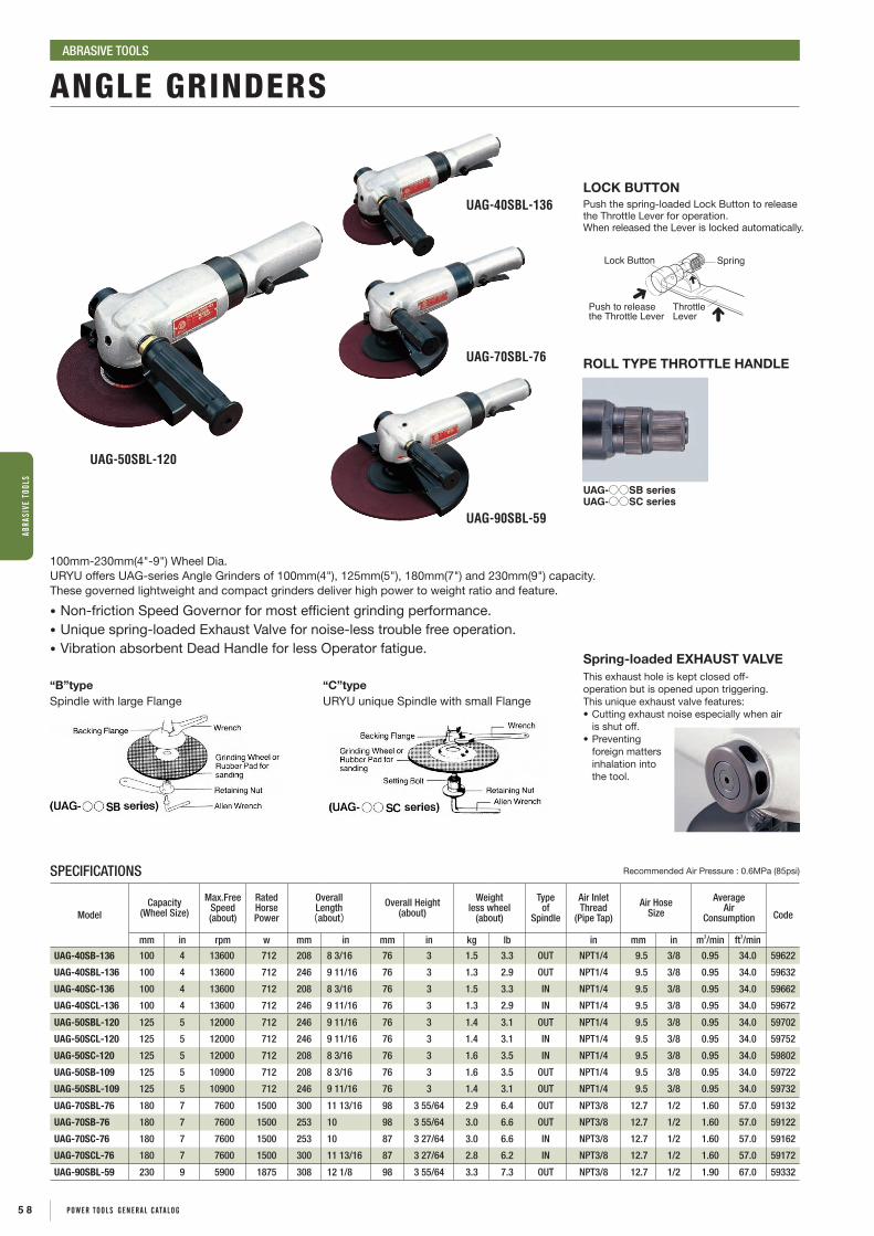
Spring-loaded EXHAUST VALVEThis exhaust hole is kept closed off-operation but is opened upon triggering.This unique exhaust valve features:•Cuttingexhaustnoiseespeciallywhenair
is shut off.•Preventing
foreign matters inhalation into the tool.
LOCK BUTTONPush the spring-loaded Lock Button to release the Throttle Lever for operation.When released the Lever is locked automatically.
ROLL TYPE THROTTLE HANDLE
Lock Button Spring
ThrottleLever
Push to releasethe Throttle Lever
UAG-70SBL-76
UAG-90SBL-59
UAG-40SBL-136
UAG-50SBL-120
UAG-○○SB seriesUAG-○○SC series
“B”type Spindle with large Flange
“C”type URYU unique Spindle with small Flange
SPECIFICATIONS Recommended Air Pressure : 0.6MPa (85psi)
ModelCapacity
(Wheel Size)
Max.FreeSpeed(about)
RatedHorsePower
OverallLength(about)
Overall Height(about)
Weightless wheel
(about)
Typeof
Spindle
Air InletThread
(Pipe Tap)
Air HoseSize
AverageAir
Consumption Code
mm in rpm w mm in mm in kg lb in mm in m3/min ft3/min
UAG-40SB-136 100 4 13600 712 208 8 3/16 76 3 1.5 3.3 OUT NPT1/4 9.5 3/8 0.95 34.0 59622
UAG-40SBL-136 100 4 13600 712 246 9 11/16 76 3 1.3 2.9 OUT NPT1/4 9.5 3/8 0.95 34.0 59632
UAG-40SC-136 100 4 13600 712 208 8 3/16 76 3 1.5 3.3 IN NPT1/4 9.5 3/8 0.95 34.0 59662
UAG-40SCL-136 100 4 13600 712 246 9 11/16 76 3 1.3 2.9 IN NPT1/4 9.5 3/8 0.95 34.0 59672
UAG-50SBL-120 125 5 12000 712 246 9 11/16 76 3 1.4 3.1 OUT NPT1/4 9.5 3/8 0.95 34.0 59702
UAG-50SCL-120 125 5 12000 712 246 9 11/16 76 3 1.4 3.1 IN NPT1/4 9.5 3/8 0.95 34.0 59752
UAG-50SC-120 125 5 12000 712 208 8 3/16 76 3 1.6 3.5 IN NPT1/4 9.5 3/8 0.95 34.0 59802
UAG-50SB-109 125 5 10900 712 208 8 3/16 76 3 1.6 3.5 OUT NPT1/4 9.5 3/8 0.95 34.0 59722
UAG-50SBL-109 125 5 10900 712 246 9 11/16 76 3 1.4 3.1 OUT NPT1/4 9.5 3/8 0.95 34.0 59732
UAG-70SBL-76 180 7 7600 1500 300 11 13/16 98 3 55/64 2.9 6.4 OUT NPT3/8 12.7 1/2 1.60 57.0 59132
UAG-70SB-76 180 7 7600 1500 253 10 98 3 55/64 3.0 6.6 OUT NPT3/8 12.7 1/2 1.60 57.0 59122
UAG-70SC-76 180 7 7600 1500 253 10 87 3 27/64 3.0 6.6 IN NPT3/8 12.7 1/2 1.60 57.0 59162
UAG-70SCL-76 180 7 7600 1500 300 11 13/16 87 3 27/64 2.8 6.2 IN NPT3/8 12.7 1/2 1.60 57.0 59172
UAG-90SBL-59 230 9 5900 1875 308 12 1/8 98 3 55/64 3.3 7.3 OUT NPT3/8 12.7 1/2 1.90 67.0 59332
ANGLE GRINDERSABRASIVE TOOLS
100mm-230mm(4"-9") Wheel Dia.URYU offers UAG-series Angle Grinders of 100mm(4"), 125mm(5"), 180mm(7") and 230mm(9") capacity. These governed lightweight and compact grinders deliver high power to weight ratio and feature.
• Non-friction Speed Governor for most efficient grinding performance.• Unique spring-loaded Exhaust Valve for noise-less trouble free operation.• Vibration absorbent Dead Handle for less Operator fatigue.
5 8 POWER TOOLS GENERAL cATALOG
ABRA
SIVE
TOO
LS

Heavy-Duty Type (Governed)
• Two speeds are available for UG-1500 series. (Higher speed for resinoid wheels and lower speed for vitrified wheels)
• Two different Throttle Handles are available for every model.
• Lever Type Handles are recommended for safer operation.
UG-1250L-72
UG-1250-72
UG-1500L-60
UG-1500-60
WHEEL SIZE
T
SPECIFICATIONS Recommended Air Pressure : 0.6MPa (85psi)
ModelCapacity
(Wheel Size)
Max.FreeSpeed(about)
RatedHorsePower
Overall Length(about)
Weightless wheel
(about)
SpindleSize
Air InletThread
(Pipe Tap)
Air HoseSize
AverageAir
Consumption Code
mm in rpm w mm in kg lb in in mm in m3/min ft3/min
UG-1250-72 125 5 7200 750 436 17 11/64 3.20 7.04 1/2-13 NPT3/8 12.7 1/2 0.90 32.7 54204
UG-1250L-72 125 5 7200 750 436 17 11/64 2.80 6.16 1/2-13 NPT3/8 12.7 1/2 0.90 32.7 54234
UG-1500-60 150 6 6000 1320 497 19 9/16 4.88 10.74 5/8-11 NPT3/8 12.7 1/2 1.30 45.9 54304
UG-1500-41 150 6 4100 975 497 19 9/16 4.88 10.74 5/8-11 NPT3/8 12.7 1/2 1.30 45.9 54314
UG-1500L-60 150 6 6000 1320 495 19 31/64 4.62 10.16 5/8-11 NPT3/8 12.7 1/2 1.30 45.9 54334
UG-1500L-41 150 6 4100 975 495 19 31/64 4.62 10.16 5/8-11 NPT3/8 12.7 1/2 1.30 45.9 54344
* Do not use vitrified wheels with higher speed type of each model.
Model Name ThicknessUG-1250 Series 13-19mmUG-1500 Series 18-25mm
HORIZONTAL GRINDERSABRASIVE TOOLS
5 9POWER TOOLS GENERAL cATALOG
ABRASIVE TOOLS

SANDERS / POLISHERSABRASIVE TOOLS
UP-80-15
UP-25DB
UP-15 UP-15N
125㎜ (5")
150㎜ (6")
UP-15N/25NB PAD UP-26NB PAD HOLED PAD Dust collection bagFor UP-15N, 25NB&26NB
548-693-3
SPECIFICATIONS Recommended Air Pressure : 0.6MPa (85psi)
ModelCapacity
(Pad/Paper Size)
Max.FreeSpeed(about)
RatedHorsePower
Overall Length(about)
Overall Height(about)
Weightless wheel
(about)
SpindleSize
Air InletThread
(Pipe Tap)
Air HoseSize
AverageAir
Consumption Code
mm in rpm w mm in mm in kg lb in in mm in m3/min ft3/min
USG-45P 125 5 12000 225 187 7 23/64 104 4 3/32 0.87 1.91 3/8-24 NPT1/4 9.5 3/8 0.55 20.0 55372
AG-180W 180 7 7000 690 315 12 13/32 111 4 3/8 2.80 6.16 5/8-11 NPT1/4 9.5 3/8 0.90 32.0 58532
UP-80-15 160 6 3/8 1500 337 - - 170 6 7/8 1.80 3.96 5/8-11 NPT1/4 9.5 3/8 0.80 28.0 54632
UP-80-40 160 6 3/8 4000 337 - - 164 6 15/32 1.80 3.96 5/8-11 NPT1/4 9.5 3/8 0.80 28.0 54642
UP-80-60 160 5/16 6000 337 - - 170 6 7/8 1.80 3.96 5/8-11 NPT1/4 9.5 3/8 0.80 28.0 54672
UP-15 125 5 8500 210 112 4 13/32 93 3 21/32 1.20 2.64 - NPT1/4 6.35 1/4 0.45 16.0 53812
UP-25DB 125 5 11000 259 212 8 11/32 120 4 3/4 1.70 3.74 - NPT1/4 6.35 1/4 0.20 7.0 55132
UP-26DB 150 6 11000 259 212 8 11/32 120 4 3/4 1.78 3.92 - NPT1/4 6.35 1/4 0.20 7.0 55182
UP-15N 125 5 9000 225 175 6 57/64 103 4 1/16 1.50 3.30 - NPT1/4 6.35 1/4 0.45 16.0 53862
UP-25NB 125 5 9000 300 250 9 23/64 119 4 23/32 1.77 3.90 - NPT1/4 9.5 3/8 0.60 21.0 54782
UP-26NB 150 6 9000 300 263 10 23/64 119 4 23/32 1.95 4.30 - NPT1/4 9.5 3/8 0.60 21.0 54792
USG-45P UP-25NB
AG-180W
AG-180W * Two different speeds available: 4,500rpm for sanding and 7,000rpm for grinding. AG-180W comes with sanding speed setting 4,500rpm with relevant accessories as standard. AG-180W can be converted into grinder model by changing speed regulator to G position and mounting wheel guard.
S
G
6 0 POWER TOOLS GENERAL cATALOG
ABRA
SIVE
TOO
LS

EXHAUST
DUST SUCTION
INTAKE
Features of Dual Action Orbital Sander UP-15, UP-25DB/26DB, UP-25NB/26NB
Movement of Single Point on Rubber Pad
Dual action type (Dual rotation movement) adopted. As the whole surface of paper attached rubber pad is rotated in ellipse and true circle, smooth finish without sanding scratch is possible.
Single action (eccentric movement only) is possible with optional pad set spindle screw (for UP-25DB/26DB, UP-25NB/26NB).
(UP-25DB、UP-25NB 551-442-0)
This is self-suction system making effective use of exhaust. No forced suction device is needed. Sanding dust is collected in the dust collection bag, through the dust collection hose.
Self-Suction Type Dual Action Orbital Sander (UP-25NB/26NB)
SANDERS / POLISHERSABRASIVE TOOLS
FEATURES
DBC
A
E
Backing Pad Assembly for UP-25/UP-26 Series
NameDimension
Part Number ModelA (mm) B (mm) C (mm) D (mm) E
Backing Pad Assembly (5”) 124 31.5 20.5 11 NPT1/4 551-409-2 UP-25DB
Backing Pad Assembly (6”) 149 30 19 11 NPT1/4 548-409-5 UP-26DB
Backing Pad Assembly (5”) 124 28 16.5 11.5 NPT1/4 548-409-3 UP-25NB
Backing Pad Assembly (6”) 149 30 19 11 NPT1/4 548-409-5 UP-26NB
Pad Set Spindle Screw
Offset of Motor Unit And Pad : 3mm
(Without Pad Set Spindle Screw) (With Pad Set Spindle Screw)
A
Dual Action Single Action
Range of Movement
A : Single Point on Rubber PadO’ : Center of PadO : Center of Motor Unit
Range of Movement
O’
A
OO’OOO
6 1POWER TOOLS GENERAL cATALOG
ABRASIVE TOOLS

Firstly, follow your local safety regulations strictly on grinders and abrasives. Following are basically required.
1. Before mounting to the Grinder, make sure that the Grinding Wheels or other Abrasives are of suitable size, shape, quality and strength to the rated speed (RPM) stamped on the name plate or tool housing.
2. The Wheel Spindle speed should be regularly checked with a tachometer to make sure whether normal speed is maintained. The governed Grinders must be checked to be sure governor mechanism is functioning properly.
3. Make sure before operation that the Abrasive Wheel should be mounted carefully and sufficiently with flanges and nuts of proper size and shape by use of the Spanners.
4. All Grinding Wheels should be closely inspected before installation and use. If cracks, nicks, or chips are found, do not use the Wheel in question.
5. Before installing a Grinding Wheel, after all Grinders repair and whenever the Grinder is issued for use, test run the Grinder by a competent person for one minute under a protected area.
6. Pay attention so that the speed of Grinder does not exceed its maximum speed specified. Do not increase air pressure for power-up.
7. Make sure to use wheel guard of suitable size and fix it properly when using Grinding Wheels of more than 50mm in diameter.
8. Never exceed maximum speed of the Abrasive Wheel to avoid dangerous breakage. Fragments from the Wheel can cause serious injury or death. Do not operate without wearing eye protector and gloves.
9. Never use the side of grinding Wheel, when a Grinding Wheel is not intentionally designed for side use.
WARNING FOR SAFETY USEABRASIVE TOOLS
6 2 POWER TOOLS GENERAL cATALOG
ABRA
SIVE
TOO
LS

DRILLS & TAPPERS
COMBINATION DRILLS
TAPPERS
6 3POWER TOOLS gENERAL CATALOg

Power is controlled by the built-in Air Regulator located on the handle.(Pistol handle type only)
DRILLSDRILLS & TAPPERS
UD-50-45
UD-50-22 UD-60-29
UD-60-04 UD-80-12
UD-50S-45
UD-50S-22 UD-60S-29
UD-60S-04 UD-80S-12
SPECIFICATIONS Recommended Air Pressure : 0.6MPa (85psi)
ModelDrilling
Capacity
FreeSpeed(about)
OverallLength(about)
Weightwith Chuck
(about)
From Centerto Outside
(about)
NominalChuckSize
Typeof
Spindle
AverageAir
Consumption Code
mm in rpm mm in kg lb mm in mm in in-thr'd m3/min ft3/minUD-50-200 3 No.5 23000 135 5 5/16 0.70 1.50 21.0 53/64 8 5/16 3/8-24UNF 0.40 14 61172UD-50-45 6 1/4 5000 145 5 23/32 0.86 1.89 21.0 53/64 8 5/16 3/8-24UNF 0.40 14 61142UD-50-22 8 5/16 2200 140 5 1/2 0.90 1.98 21.0 53/64 8 5/16 3/8-24UNF 0.40 14 61102UD-60-29 8 5/16 2900 165 6 1/2 1.10 2.43 22.5 57/64 8 5/16 3/8-24UNF 0.50 18 61252UD-60-20 8 5/16 2000 180 7 1/8 1.20 2.64 22.5 57/64 8 5/16 3/8-24UNF 0.50 18 61242UD-60-15 8 5/16 1600 180 7 1/8 1.20 2.64 22.5 57/64 8 5/16 3/8-24UNF 0.50 18 61232UD-60-07 13 1/2 700 219 8 5/8 1.40 3.08 22.5 57/64 13 1/2 1/2-20UNF 0.50 18 61212UD-60-04 13 1/2 500 220 8 5/8 1.40 3.08 22.5 57/64 13 1/2 1/2-20UNF 0.50 18 61202UD-80-12 13 1/2 1200 216 8 1/2 1.80 3.96 26.0 1 1/64 13 1/2 1/2-20UNF 0.65 23 61372UD-80-07 13 1/2 700 239 9 13/32 2.30 5.06 26.0 1 1/64 13 1/2 1/2-20UNF 0.65 23 61342UD-80-04 16 5/8 400 247 9 23/32 2.90 6.39 26.0 1 1/64 16 5/8 5/8-16UN 0.65 23 61302
*Air Hose Size (Inside Diameter) : 9.5mm (3/8") *Air Inlet Thread : NPT1/4"
SPECIFICATIONS Recommended Air Pressure : 0.6MPa (85psi)
ModelDrilling
Capacity
FreeSpeed(about)
OverallLength(about)
Weightwith Chuck
(about)
From Centerto Outside
(about)
NominalChuckSize
Typeof
Spindle
AverageAir
Consumption Code
mm in rpm mm in kg lb mm in mm in in-thr'd m3/min ft3/minUD-50S-200 3 No.5 23000 193 7 7/8 0.70 1.50 21.0 53/64 8 5/16 3/8-24UNF 0.40 14 61972UD-50S-45 6 1/4 5000 210 8 9/32 0.85 1.87 21.0 53/64 8 5/16 3/8-24UNF 0.40 14 61942UD-50S-22 8 5/16 2200 205 8 1/16 0.83 1.83 21.0 53/64 8 5/16 3/8-24UNF 0.40 14 61902UD-60S-29 8 5/16 2900 227 8 15/16 1.05 2.32 22.5 57/64 8 5/16 3/8-24UNF 0.50 18 61772UD-60S-20 8 5/16 2000 238 9 3/8 1.15 2.54 22.5 57/64 8 5/16 3/8-24UNF 0.50 18 61742UD-60S-15 8 5/16 1600 238 9 3/8 1.15 2.54 22.5 57/64 8 5/16 3/8-24UNF 0.50 18 61732UD-60S-07 13 1/2 700 272 10 23/32 1.35 2.98 22.5 57/64 13 1/2 1/2-20UNF 0.50 18 61702UD-60S-04 13 1/2 500 279 10 63/64 1.35 2.98 22.5 57/64 13 1/2 1/2-20UNF 0.50 18 61712UD-80S-12 13 1/2 1200 277 10 29/32 1.60 3.53 26.0 1 1/64 13 1/2 1/2-20UNF 0.65 23 61392UD-80S-07 13 1/2 700 300 11 13/16 2.10 4.73 26.0 1 1/64 13 1/2 1/2-20UNF 0.65 23 61352UD-80S-04 16 5/8 400 307 12 3/32 2.70 5.95 26.0 1 1/64 16 5/8 5/8-16UN 0.65 23 61332UD-80-12G 13 1/2 1200 282 11 7/64 2.30 5.06 26.0 1 1/64 13 1/2 1/2-20UNF 0.65 23 61382UD-80-07G 13 1/2 700 305 12 1/64 2.80 6.16 26.0 1 1/64 13 1/2 1/2-20UNF 0.65 23 61362UD-80-04G 16 5/8 400 313 12 21/64 3.40 7.50 26.0 1 1/64 16 5/8 5/8-16UN 0.65 23 61322
*Air Hose Size (Inside Diameter) : 9.5mm (3/8") *Air Inlet Thread : NPT1/4"
6 4 POWER TOOLS gENERAL CATALOg
DRIL
LS &
TAP
PERS

DRILLSDRILLS & TAPPERS
UD-60S-29C
For UD-60 series : 613-720-0 Dead Handle / 612-730-0 Dead Handle ConnectorFor UD-80 series : 613-720-0 Dead Handle / 613-730-0 Dead Handle Connector
Dead Handle & Dead Handle Connector
C
H
C
H
Head SizesModel
C H
mm in mm in
UD-50S-22A 10.0 25/64 48.0 1 57/64
UD-60S-29C 17.0 43/64 90.0 3 35/64
UD-60S-15C 17.0 43/64 90.0 3 35/64
UD-50S-22A
OPTION
Tap Pilot Hole Size (mm)
Bolt Size Pilot Hole Size
M3M4M5M6M7M8M9M10M12M14
2.403.254.15.06.06.87.88.510.212.0
3mm
4mm
5mm
6mm
8mm
10mm
12mm
13mm
14mm
16mm
19mm
22mm
23mm
25mm
28mm
32mm
44mm
50mm
75mm
100mm
Material
Drill Size
Rotation Speed【rpm】10020 1000 100005000500 20000
Stainless SteelSoft SteelPlastic
(Drilling Speed 9~12m/min)(Drilling Speed 24~33m/min)(Drilling Speed 30~45m/min)
AluminiumWood
(Drilling Speed 60~90m/min)(Drilling Speed 90~120m/min)
50
SPECIFICATIONS Recommended Air Pressure : 0.6MPa (85psi)
ModelDrilling
Capacity
FreeSpeed(about)
OverallLength(about)
Weightwith Chuck
(about)
Heightwith Chuck
(about)
From Centerto Outside
(about)
NominalChuckSize
Typeof
Spindle
AverageAir
Consumption Code
mm in rpm mm in kg lb mm in mm in mm in in-thr'd m3/min ft3/min
UD-50S-45A 4 No.8 5000 253 9 31/32 0.90 1.98 40 1 57/64 21.0 53/64 - - 1/4-28UNF 0.40 14 62042
UD-50S-22A 4 No.8 2200 248 9 49/64 0.88 1.94 40 1 57/64 21.0 53/64 - - 1/4-28UNF 0.40 14 62002
UD-60S-29C 8 5/16 2900 276 10 55/64 1.52 3.34 90 3 35/64 22.5 57/64 8 5/16 3/8-24UNF 0.50 18 61872
UD-60S-15C 8 5/16 1600 283 11 9/64 1.60 3.52 90 3 35/64 22.5 57/64 8 5/16 3/8-24UNF 0.50 18 61832
*Air Hose Size (Inside Diameter) : 9.5mm (3/8") *Air Inlet Thread : NPT1/4"
SELECTION GUIDE
DRILL ADAPTER (for UD-50S Series)
Flat Point Screw
28mm
A
20mm
12mm
A
19mm
φ21
1/4-28UNF
26mm
7mm 19mm
CONE JAW CHUCK (for UD-50S Series)
Capacity : up to 1/4" or 6.35mmPart Number : 923-100-0
Drill Adapter
Dimensions A (mm) Part Number
1.0 924-020-02.0 924-001-03.0 924-007-04.0 924-011-05.0 924-013-06.0 924-015-07.0 924-017-08.0 924-016-0
*Other sizes are also available. Please contact your nearest URYU distributors.
6 5POWER TOOLS gENERAL CATALOg
DRILLS & TAPPERS

UT-66B-07
UT-60-04 UT-60S-07
Reversing
Forwarding
UT-66 series reversible drills have the double trigger handle for quick and frequent switchover of rotation.
Double-Trigger Handle
Power is controlled by the built-in Air Regulator located on the handle.
UT-60-07UT-60-04
Name Part Number
φ13 Chuck 923-060-0φ13 Taper Adapter 682-732-0φ10 Chuck 923-053-0φ10 Taper Adapter 678-732-7
*Tapping capacity is up to nominal Standard chuck size.
DRILLS
TAPPERS
DRILLS & TAPPERS
DRILLS & TAPPERS
Size up of Chuck is possible.
OPTION
923-060-0
682-732-0
923-053-0
678-732-7
SPECIFICATIONS Recommended Air Pressure : 0.6MPa (85psi)
ModelTappingCapacity
FreeSpeed(about)
OverallLength(about)
Weightwith Chuck
(about)
From Centerto Outside
(about)
AverageAir
Consumption Code
mm in rpm mm in kg lb mm in m3/min ft3/minUT-66B-15 6 1/4 1500 183 7 7/32 1.32 2.90 25.0 31/32 0.4 14.4 68102UT-66B-07 8 5/16 800 196 7 23/32 1.42 3.12 25.0 31/32 0.4 14.4 68132UT-60-07 8 5/16 680 244 9 39/64 1.80 3.96 22.5 57/64 0.5 18.0 67852UT-60-04 8 5/16 400 244 9 39/64 1.80 3.96 22.5 57/64 0.5 18.0 67872UT-60S-07 8 5/16 680 316 12 7/16 1.65 3.63 22.5 57/64 0.5 18.0 68022UT-60S-04 8 5/16 400 316 12 7/16 1.65 3.63 22.5 57/64 0.5 18.0 68002
Air Inlet Thread : NPT1/4" for UT-66B-15~UT-60S-04 Air Hose Size : 9.5mm (3/8") for UT-66B-15~UT-60S-04Nominal Chuck Size : 8mm (5/16") for UT-66B-07~UT-60S-04
"Push-Pull" Auto Reversing Clutches
Push forward for tapping in. Forwarding
Pull back for tapping out. Reversing
Chuck Adaptor
Smooth and accurate operations for many kinds of applications, such as drilling, tapping, reaming and tube rolling, etc.
SELF-RETURNING ROLL TYPE THROTTLE HANDLE
Reversing Ring
Spring-Loaded Roll type Throttle Handle
SPECIFICATIONS Recommended Air Pressure : 0.6MPa(85psi)
Model TypeDrilling
Capacity
FreeSpeed(about)
OverallLength(about)
Weight(about)
From Centerto Outside
(about)
FeedLength(about)
AirHoseSize
AverageAir
Consumption Code
mm in rpm mm in kg lb mm in mm in mm in m3/min ft3/min
URD-22RR Self-Returning 22.0 7/8 600 442 17 13/32 5.8 12.8 39 1 17/32 70 2 3/4 12.7 1/2 1.3 46 63242
Air Inlet Thread : NPT3/8" for URD-22RR
6 6 POWER TOOLS gENERAL CATALOg
DRIL
LS &
TAP
PERS

PERCUSSION TOOLS
R IVETINg HAMMERS
IMPACT CUTTERS
FLUX CHIPPERS
CHIPPINg HAMMERS
6 7POWER TOOLS gENERAL CATALOg

BRH-1U(R)
SBH-0 SBH-1A(R)
BRH-1US(R)
BRH-5U(R)
SUPER VIBRATION-PROOF TYPE
STANDARD TYPE
RIVETING HAMMERS PERCUSSION TOOLS
SPECIFICATIONS Recommended Air Pressure : 0.6MPa (85psi)
Model
Riveting CapacityBlow
Per Min.(about)
OverallLength(about)
Weight LessRivet Set(about)
PistonDiameter(about)
PistonStroke(about)
Air InletThread
(Pipe Tap)
AirHoseSize
AverageAir
ConsumptionCode
Duralumin Steel
mm in mm in bpm mm in kg lb mm in mm in in mm in m3/min ft3/min R H
SBH-0 2.3 No.2 - - 6500 123 4 27/32 0.32 0.7 10.00 25/64 23 29/32 NPT1/8 6.35 1/4 0.10 3.5 70012 -
SBH-1A(R,H) 2.6 No.3 - - 4000 209 8 15/64 0.86 1.9 11.11 7/16 56 2 3/16 NPT1/4 6.35 1/4 0.15 5.0 70112 78412
BRH-1U(R,H) 3.2 No.5 2.4 No.3 2800 122 4 15/16 1.05 2.4 14.30 9/16 38 1 1/2 NPT1/4 9.5 3/8 0.34 12.0 70512 78612
BRH-1US(R,H) 3.2 No.5 2.4 No.3 2800 180 7 1/8 1.00 2.2 14.30 9/16 38 1 1/2 NPT1/4 9.5 3/8 0.34 12.0 70612 78712
BRH-1UG(R,H) 3.2 No.5 2.4 No.3 2800 187 7 3/8 1.78 3.9 14.30 9/16 38 1 1/2 NPT1/4 9.5 3/8 0.34 12.0 70712 78812
BRH-5U(R,H) 6.4 1/4 4.8 No.10 1800 189 7 7/16 1.40 3.1 12.70 1/2 100 4 NPT1/4 9.5 3/8 0.37 13.0 71012 78912
BRH-5US(R,H) 6.4 1/4 4.8 No.10 1800 246 9 11/16 1.45 3.2 12.70 1/2 100 4 NPT1/4 9.5 3/8 0.37 13.0 71112 79012
BRH-5UG(R,H) 6.4 1/4 4.8 No.10 1800 258 10 5/32 2.13 4.7 12.70 1/2 100 4 NPT1/4 9.5 3/8 0.37 13.0 71212 79112
SPECIFICATIONS Recommended Air Pressure : 0.6MPa (85psi)
Model
Riveting CapacityBlow
Per Min.(about)
OverallLength(about)
Weight LessRivet Set(about)
PistonDiameter(about)
PistonStroke(about)
Air InletThread
(Pipe Tap)
AirHoseSize
AverageAir
ConsumptionCode
Duralumin Steel
mm in mm in bpm mm in kg lb mm in mm in in mm in m3/min ft3/min R H
BRH-1UD (R,H) 3.2 No.5 2.4 No.3 2800 143 5 5/8 1.40 3.1 14.30 9/16 38 1 1/2 NPT1/4 9.5 3/8 0.34 12.0 70882 70892
BRH-5UD (R,H) 6.4 1/4 4.8 No.10 1800 211 8 5/16 1.65 3.6 12.70 1/2 100 4 NPT1/4 9.5 3/8 0.37 13.0 70942 70952
BRH-1USD (R,H) 3.2 No.5 2.4 No.3 2800 272 10 45/64 1.60 3.5 14.30 9/16 38 1 1/2 NPT1/4 9.5 3/8 0.34 12.0 70922 70932
BRH-5USD (R,H) 6.4 1/4 4.8 No.10 1800 340 13 25/64 1.90 4.2 12.70 1/2 100 4 NPT1/4 9.5 3/8 0.37 13.0 70982 70992
BRH-1UD
BRH-1USD
BRH-5UD
BRH-5USD
Super vibration-proof hammers reduce vibration exposure stress and fatigue of operators. Total vibration value is less than 2.5m/s2.
6 8 POWER TOOLS gENERAL CATALOg
PERC
USSI
ON T
OOLS
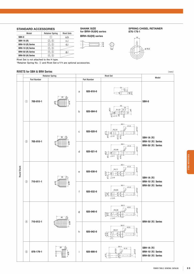
RIVETS for SBH & BRH Series (mm)
Retainer Spring Rivet SetModel
Part Number Part Number
Roun
d Sh
ank
① 700-810-1
φ16
φ9
22
a 920-810-0
5525R1.3
φ12φ8
φ8
SBH-0
b 920-004-0φ3.5φ6.4
1.2
R1.87
55
φ8
φ8
φ12
R1.325
② 705-810-1
φ28
φ13
36
c 920-020-0
R12.7
φ19
R2.34
1.6
φ7.5
φ4.5
41.690.1
φ10.2
φ12.7
SBH-1A(R)BRH-1U(R) Series
BRH-5U(R) Series
d 920-021-0
R12.7
φ19φ5.7φ8.9
φ12.7
φ10.2
41.690.1
2.1
R2.98
③ 710-811-1
φ28
φ16
35
e 920-030-0 R12.7
φ19
φ16
φ10.2
90.141.6
φ10.6
φ7.2
2.8
R3.71
SBH-1A(R)BRH-1U(R) Series
BRH-5U(R) Series
f 920-032-0 R12.7
φ19
φ16
90.141.6
φ10.2
φ9
φ12.7
3.5
R4.65
④ 710-812-1
φ28
φ19
40
g 920-040-0
φ19
φ13.5
φ10
φ25.4 φ10.2
90.343.8
R12.7
4.2
R5.08
BRH-5U(R) Series
h 920-042-0 φ10.2
43.8
R12.7
φ25.4
φ19
φ16
90.3
7
φ19
R8.07
⑤ 876-179-1
φ28
32
i 920-800-0
φ10.2
φ19
φ15.9
φ19
84.441.6
R12.7
SBH-1A(R)BRH-1U(R) Series
BRH-5U(R) Series
8.6
φ10.2
φ19
15
φ16.5
BRH-5U(H) series
SHANK SIZEfor BRH-5U(H) series
SPRING CHISEL RETAINER876-179-1
STANDARD ACCESSORIESModel Retainer Spring Rivet Sets
SBH-0 ① a,bSBH-1A (R) ②,⑤ c,iBRH-1U (R) Series ②,⑤ d,iBRH-1U (H) Series ②,⑤BRH-5U (R) Series ④,⑤ g,iBRH-5U (H) Series ④,⑤
Rivet Set is not attached to the H type.*Retainer Spring No. ③ and Rivet Set e/f/h are optional accessories.
RIVETING HAMMERS PERCUSSION TOOLS
6 9POWER TOOLS gENERAL CATALOg
PERCUSSION TOOLS

BRH-7(R)UFC-0N
BRH-7 Retainer Spring
φ28
33 12.5
φ13.5 ○714-813-2
B
13.543
38
27°
A22
12.312.7
14.5
B
56
A1.6
13.543
12.312.7
14.5
Chisels for UFC-0N, 1N
Chisel Part NumberDimension(mm)
A B
Scraper○ 921-201-0 31.5 150
Flat Chisel
921-202-0 35 158
921-206-0 60 140
IMPACT CUTTERS / FLUX CHIPPERSPERCUSSION TOOLS
OPTION
SPECIFICATIONS Recommended Air Pressure : 0.6MPa (85psi)
Model
BlowPer Min.(about)
OverallLength(about)
Weight LessChisel(about)
PistonDiameter(about)
PistonStroke(about)
Air InletThread
(Pipe Tap)
AirHoseSize
AverageAir
Consumption Code
bpm mm in kg lb mm in mm in in mm in m3/min ft3/min
BRH-7(R) 3400 168 6 39/64 1.64 3.60 19.05 3/4 50 1 31/32 NPT1/4 9.5 3/8 0.48 17.0 71412
BRH-7(H) 3400 168 6 39/64 1.64 3.60 19.05 3/4 50 1 31/32 NPT1/4 9.5 3/8 0.48 17.0 77112
UFC-0N 5300 180 7 1/8 1.38 3.04 25.00 63/64 28 1 1/4 NPT1/4 9.5 3/8 0.3 10.7 75412
UFC-1N 4200 190 7 1/2 1.50 3.30 25.00 63/64 34 1 11/32 NPT1/4 9.5 3/8 0.3 10.7 75712
R= Round Shank H=Hex. Shank BRH-7= with Built-in Air Regulator
Shank Size Of Rivet Sets
φ8 φ10.5 φ10.2
25
41.5
41.6
φ8
39.21
φ10.5
φ19
39.21
43
φ10.2
φ10.2
8.6
13.5
12.7
14.5
12.3
φ8 φ10.5 φ10.2
25
41.5
41.6
φ8
39.21
φ10.5
φ19
39.21
43
φ10.2
φ10.2
8.6
13.5
12.7
14.5
12.3
φ8 φ10.5 φ10.2
25
41.5
41.6
φ8
39.21
φ10.5
φ19
39.21
43
φ10.2
φ10.2
8.6
13.5
12.7
14.5
12.3
φ8 φ10.5 φ10.2
25
41.5
41.6
φ8
39.21
φ10.5
φ19
39.21
43
φ10.2
φ10.2
8.6
13.5
12.7
14.5
12.3
φ8 φ10.5 φ10.2
25
41.5
41.6
φ8
39.21
φ10.5
φ19
39.21
43
φ10.2
φ10.2
8.6
13.5
12.7
14.5
12.3
φ8 φ10.5 φ10.2
25
41.5
41.6
φ8
39.21
φ10.5
φ19
39.21
43
φ10.2
φ10.2
8.6
13.5
12.7
14.5
12.3
SBH-0 SBH-1A, BRH-1U & 5U BRH-7 UFC series
RoundShank
Hex.Shank
RoundShank
RoundShank
Hex.Shank
FluxChippers
43122
Chisels For BRH-7
43103
43109
43125
43109
43109
43135
43135
43125
43122
4355
43109
43103
43109
43125
43109
43109
43135
43135
43103
43109
43125
43109
43109
43135
43135
43103
43109
43125
43109
43109
43135
43135
43103
43109
43125
43109
43109
43135
43135
43103
43109
43125
43109
43109
43135
43135
43103
43109
43125
43109
43109
43135
43135
ChiselPart Number
Round Shank Hex. Shank
Blank○ 921-134-0(φ13) ○ 921-135-0(φ13)
*921-136-0(φ12.7) *921-137-0(φ12.7)
Flat ○ (7")921-087-0 ○ 921-127-0
Sheet Metal(A) ○ 921-096-0 ○ 921-115-0
Sheet Metal(B) 921-092-0 921-117-0
Spot Weld Breaker ○ 921-085-0 ○ 921-125-0
Taper Punch 921-091-0 921-121-0
Bushing Remover 921-094-0 921-119-0
Fork 921-097-0 921-122-0
Hammer 921-098-0 921-123-0
Scraper ○ 921-088-0 ○ 921-128-0
Tail Pipe Cutter 921-093-0 921-118-0
Double Blade Panel Cutter 921-089-0 921-129-0
*If you use small Retainer Spring 705-810-1, use φ12.7 chisel. Standard Chisels are marked with "○"
7 0 POWER TOOLS gENERAL CATALOg
PERC
USSI
ON T
OOLS

AA-00(R)
AA-20(R)
PB-20(R)
Chisel Retainer Assembly 727-847-6 AA-20,30,40, PB-20,30 Standard Accessories. (Chisel not included)
CHIPPING HAMMERSPERCUSSION TOOLS
OPTION
CHISELS for AA-00 SERIES (Collared type)
φ12.7 46㎜ 10.5㎜ 46㎜ φ12.7 46㎜ 10.5㎜ 46㎜ Round Shank Hex. Shank
CHISELS for AA & PB SERIES60
60
φ17.5
20
φ17.5
60
60
14.7㎜
14.7㎜
60
60
φ17.5
20
φ17.5
60
60
14.7㎜
14.7㎜ Round Shank Hex. Shank
POINT shapeOverall Length Part Number
mm in Round Shank Hex.Shank
200 7 7/8" 921-224-0 921-049-0
176 6 15/16" 877-035-1 921-221-0
220 8 21/32" 921-225-0 921-220-0
φ12.7 46㎜ 10.5㎜ 46㎜
φ12.7 46㎜ 10.5㎜ 46㎜
POINT shapeOverall Length Part Number
mm in Collared Type
200 7 7/8"R 921-072-0
H 921-075-0
220 8 21/32"R 921-070-0
H 921-073-0
200 7 7/8" R 921-071-0
220 8 21/32" H 921-074-0
φ12.7 46㎜ 10.5㎜ 46㎜
φ12.7 46㎜ 10.5㎜ 46㎜
SPECIFICATIONS Recommended Air Pressure : 0.6MPa (85psi)
Model
Chisel Shank SizeBlow
Per Min.(about)
OverallLength(about)
Weight LessChisel(about)
PistonDiameter(about)
PistonStroke(about)
Air InletThread
(Pipe Tap)
AirHoseSize
AverageAir
ConsumptionCode
Round Hexagonal
mm in mm in bpm mm in kg lb mm in mm in in mm in m3/min ft3/min R H
AA-00(R,H) 12.7 1/2 10.5 3/8 2700 228 8 31/32 2.3 5.00 20.0 25/32 50 1 31/32 NPT1/4 9.5 3/8 0.35 12.3 71952 77252
AA-20(R,H) 17.5 5/8 14.7 9/16 2300 270 10 5/8 5.3 11.60 28.0 1 7/64 55 2 5/32 NPT3/8 12.7 1/2 0.60 21.1 72152 77452
AA-30(R,H) 17.5 5/8 14.7 9/16 2000 298 11 23/32 5.7 12.50 28.0 1 7/64 79 3 1/8 NPT3/8 12.7 1/2 0.60 21.1 72252 77552
AA-40(R,H) 17.5 5/8 14.7 9/16 1450 340 13 3/8 6.1 13.40 28.0 1 7/64 111 4 3/8 NPT3/8 12.7 1/2 0.60 21.1 72352 77652
PB-20(R,H) 17.5 5/8 14.7 9/16 1900 350 13 25/32 6.6 14.50 28.5 1 1/8 76 3 NPT3/8 12.7 1/2 0.80 28.0 72752 77852
PB-30(R,H) 17.5 5/8 14.7 9/16 1500 397 15 5/8 7.1 15.60 28.5 1 1/8 102 4 1/62 NPT3/8 12.7 1/2 0.80 28.0 72852 77952
7 1POWER TOOLS gENERAL CATALOg
PERCUSSION TOOLS

Compressor
You can refer to the table 1 to find the theoretical consumption energy of compressor, which is created through the adiabatic compression, to compress 1m3/min (normal cubic meter per minute) of free air to the various pressure levels. It is highly recommended that you should make the consumption energy value greater than the actual value by taking into consideration the machine efficiency including friction loss caused by compressor.
The consumption energy of compressor providing a pneumatic tool with 1m3/min (normal cubic meter per minute) of air at the gauge pressure 0.6MPa will be some 6.5kW or larger, if we consider the possible losses.
The table 4 refers to the major compressor power, which is sorted by tool category and model number, to operate a tool based on the catalogue air consumption value.It takes long for a tool to complete a job at 0.4MPa as a compressor generates less power. On the other hand, it will not take long for a tool to do at 0.6MPa as a compressor generates more power. You should decide which helps you save cost, based on your various applications. The table 2 gives you an idea of coefficient of operation. The value to operate a number of tools simultaneously is smaller as there are an increasing number of tools in operation. The air consumption rate refers to the value in which a tool is used continuously for 1 minute. It is recommended, as shown in the table 3, that you should make the consumption energy value smaller than the actual value when you operate tools in the above-mentioned discontinuous operation and that you should make the consumption energy value larger than the actual value when you operate tools in the above-mentioned continuous condition.
Q≧6.5 kW × (V×n + V×n + V×n ・・・) × K × S × αQ : Energy needed for compressor (kW)
V : Air consumption per tool (m3/min (normal cubic meter per minute))
n : Number of tool
K : Coefficient of multiple tools in operation (table 2)
S : Coefficient of tool usage (table 3)
① Continuous operation: 1.0
Tool model for this category: Grinder, Sander, and Percussion Tool
② Discontinuous operation: 0.5
Tool model for this category: Oil-pulse tool, Impact Wrench, and Screwdriver
α : Loss caused by air leakage from connection between pipes
Theoretical Consumption Energy of Compressor
Energy Needed for Compressor
Table 1
Gauge pressure
Single Stage Compression (Adiabatic Compression)
Theoretical Consumption
Energy
Machine Efficiency
(15% Included)
Various Losses(30% Included)
MPa kW kW kW0.3 2.84 3.27 4.250.4 3.41 3.92 5.100.5 3.91 4.49 5.840.6 4.35 5.00 6.500.7 4.74 5.45 7.09
Table 4
Category Tool ModelAir Consumption Energy Needed for
Compressor
m3/min (kW)
Oil-pulse ToolUAT60 0.35 2.28
UL90 0.53 3.45
Impact WrenchUW-6SLRK 0.35 2.28
UW-13SRK 0.45 2.93
ScrewdriverUS-3.5A 0.20 1.02
US-5W 0.30 1.53
GrinderUG-38N 0.40 2.60
USG-7S 1.10 7.15
DrillUD-60-29 0.50 3.25
UD-80-12 0.65 4.23
Percussion ToolSBH-1A 0.15 0.98
BRH-7 0.45 2.93
Note: Value for tools except Screwdriver: 0.6MPa at gauge Value for Screwdriver: 0.4MPa at gauge.
Table 2Number of Tool Coefficient of Multiple Tools in Operation
1〜5 1.06〜10 0.811〜20 0.721〜30 0.631〜50 0.550〜100 0.4
Table 3Operation Coefficient of Tool Usage
Continuous Operation 1.0Discontinuous Operation 0.5
7 2 POWER TOOLS gENERAL CATALOg
PERC
USSI
ON T
OOLS

TESTERS & ACCESSORIES
D IgITAL TORQUE TESTERS
TESTERS
ACCESSORIES
7 3POWER TOOLS gENERAL CATALOg

UDT-200 & UDT-500
The built-in NiMH battery operation gives you hand-carry mobile use in your assembly site especially for pulse-tools’ commencement of one day operation. AC power source from your plug can be used together. 11-hour continuous operation by battery is possible. Full recharging time is approx. 4-hours. Memory function can store maximum 250 torque data. Torque check and adjustment for angle nutrunner and shut-off pulse tool using optional soft-joint attachment for traceability.Red color LED display gives clear visual confirmation. PC output terminal RS-232C is built in the UDT series. Torque transducer mounted in pick-up has optimum function to measure oil-pulse tool.
UDT-200 & UDT-500 series help you check the performance of oil-pulse tool and hand torque wrench at regular intervals, allowing you to store and download the data.
FEATURES
DIGITAL TORQUE TESTERSTESTERS & ACCESSORIES
SPECIFICATIONS
Model Applicable Tool TypeRecommended
TorqueCapacity Range
BlowCapacityRange
AccuracyDimensionsmm(about)(W × D × H)
WeightKg(about)
Code(A)(E)
Accessories
UDT -200A (115V) -200E (230V)
Pulse Wrench, Angle Nutrunner(Soft-joint attachment assembly is required to measure shut-off type pulse wrench and angle nutrunner.)Hand torque wrench*Never use impact wrench
15-200N.m10-150ft-Ib150-2000kgf.cm
0-99 blows( * )
±0.5% atrated output
Amplifier(198 × 171 × 115)Pick-up(245 × 125 × 75)
Amplifier(1.7)Pick-up(8.5)
8310283112
Socket Adapter (3/8) 836-520-0Socket Adaptor (1/2) 836-520-1TX-C46E-75 (Socket Bit) 919-700-0
AC Adaptor (120V) 910-217-0AC Adaptor (230V) 910-218-0
UDT -500A (115V) -500E (230V)
Pulse Wrench, Angle Nutrunner(Soft-joint attachment assembly is required to measure shut-off type pulse wrench and angle nutrunner.)Hand torque wrench*Never use impact wrench
150-500N.m110-370ft-Ib15-50kgf.m
0-99 blows( * )
±0.5% atrated output
Amplifier(198 × 171 × 115)Pick-up(280 × 150 × 90)
Amplifier(1.7)Pick-up(15.0)
8313283142
Socket Adapter (1/2) 836-520-7Socket Adaptor (5/8) 836-520-8Socket Adaptor (3/4) 836-520-9AC Adaptor (120V) 910-217-0AC Adaptor (230V) 910-218-0
(*) On condition that blow measurements start when input torque exceeds 60% of peak torque. Operating Voltage: 120V for UDT-**A , 220V for UDT-**E Operating Environment: (10-40˚C) Humidity (20-80%), No Dew.
UDT-200 UDT-500
(M8)836-890-1
(M14)878-840-1
(M20)878-807-1(M10)836-890-2
(M16)878-800-1
(M12)836-890-5
(M18)878-804-1(M10)836-890-7 (M12)836-890-9(M8)878-740-1
OPTIONSoft-joint Attachment Assembly
Choose the correct size for your usage.Other optional soft-joint attachment assemblies are available. Please contact your nearest URYU distributor.
For pulse tools or angle nutrunner
For angle nutrunner
7 4 POWER TOOLS gENERAL CATALOg
TEST
ERS
& AC
CESS
ORIE
S
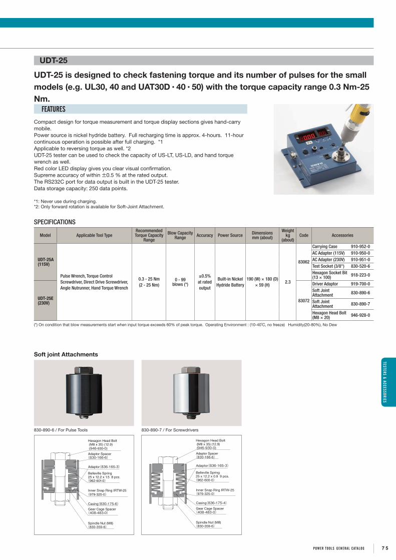
UDT-25
Compact design for torque measurement and torque display sections gives hand-carry mobile. Power source is nickel hydride battery. Full recharging time is approx. 4-hours. 11-hour continuous operation is possible after full charging. *1Applicable to reversing torque as well. *2UDT-25 tester can be used to check the capacity of US-LT, US-LD, and hand torque wrench as well. Red color LED display gives you clear visual confirmation.Supreme accuracy of within ±0.5 % at the rated output.The RS232C port for data output is built in the UDT-25 tester. Data storage capacity: 250 data points.
*1: Never use during charging.*2: Only forward rotation is available for Soft-Joint Attachment.
UDT-25 is designed to check fastening torque and its number of pulses for the small models (e.g. UL30, 40 and UAT30D・40・50) with the torque capacity range 0.3 Nm-25 Nm.
FEATURES
DIGITAL TORQUE TESTERSTESTERS & ACCESSORIES
SPECIFICATIONS
Model Applicable Tool TypeRecommended Torque Capacity
Range
Blow Capacity Range Accuracy Power Source Dimensions
mm (about)
Weight kg
(about)Code Accessories
UDT-25A (115V)
Pulse Wrench, Torque Control Screwdriver, Direct Drive Screwdriver, Angle Nutrunner, Hand Torque Wrench
0.3 - 25 Nm(2 - 25 Nm)
0 - 99blows (*)
±0.5% at rated output
Built-in Nickel Hydride Battery
190 (W) × 180 (D) × 59 (H)
2.3
83062
Carrying Case 910-952-0AC Adapter (115V) 910-950-0AC Adapter (230V) 910-951-0Test Socket (3/8") 830-520-6Hexagon Socket Bit (13 × 100) 918-223-0
UDT-25E (230V) 83072
Driver Adaptor 919-700-0Soft Joint Attachment 830-890-6
Soft Joint Attachment 830-890-7
Hexagon Head Bolt (M8 × 20) 946-928-0
(*) On condition that blow measurements start when input torque exceeds 60% of peak torque. Operating Environment : (10-40˚C, no freeze) Humidity(20-80%), No Dew
Soft joint Attachments
830-890-6 / For Pulse Tools
Casing(830-175-6)Gear Cage Spacer(408-483-0)
Hexagon Head Bolt (M8 x 35) (12.9) (946-930-0)
Adaptor Spacer(830-166-6)
Adaptor(836-165-3)
Spindle Nut (M8)(830-359-6)
Belleville Spring25 x 12.2 x 1.5 8 pcs.(962-601-0)
Inner Snap Ring IRTW-25(979-325-0)
830-890-7 / For Screwdrivers
Gear Cage Spacer(408-483-0)
Adaptor(836-165-3)
Casing(836-175-4)
Spindle Nut (M8)(830-359-6)
Adaptor Spacer(830-166-6)
Hexagon Head Bolt (M8 x 35) (12.9) (946-930-0)
Belleville Spring25 x 12.2 x 0.9 9 pcs.(962-600-0)
Inner Snap Ring IRTW-25(979-325-0)
7 5POWER TOOLS gENERAL CATALOg
TESTERS & ACCESSORIES
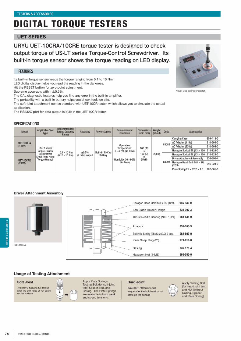
Usage of Testing Attachment
Soft Joint
Typically 3 turns to full torque after the bolt head or nut seats on the surface.
Hard Joint
Typically 1/10 turn to full torque after the bolt head or nut seats on the surface
Apply Testing Bolt (for heard joint test) and Nut (without Casing, Spacer and Plate Spring).
Apply Plate Springs, Testing Bolt (for soft-joint test) Spacer, Nut, and Casing. The Plate Springs are available in both weak and strong tensions.
URYU UET-10CRA/10CRE torque tester is designed to check output torque of US-LT series Torque-Control Screwdriver. Its built-in torque sensor shows the torque reading on LED display.
Its built-in torque sensor reads the torque ranging from 0.1 to 10 Nm. LED digital display helps you read the reading in the darkness. Hit the RESET button for zero point adjustment.Supreme accuracy: within ±0.5%.The CAL diagnostic features help you find any error in the built-in amplifier. The portability with a built-in battery helps you check tools on site. The soft-joint attachment comes standard with UET-10CR tester, which allows you to simulate the actual application.The RS232C port for data output is built in the UET-10CR tester.
UET SERIES
FEATURES
DIGITAL TORQUE TESTERSTESTERS & ACCESSORIES
Never use during charging.
Driver Attachment Assembly
836-890-4
Hexagon Head Bolt (M8 x 35) (12.9) 946-930-0
San Blade Holder Flange 836-397-3
988-835-0
Adaptor 836-165-3
Belleville Spring (25x12.2x0.9) 9 pcs. 962-600-0
Inner Snap Ring (25) 979-018-0
Casing 836-175-4
Hexagon Nut (1-M8) 960-050-0
Thrust Needle Bearing (NTB 1024)
SPECIFICATIONS
Model Applicable Tool Type
Recommended Torque Capacity
RangeAccuracy Power Source Environmental
ConditionDimensions(unit: mm)
Weight(about) Code Accessories
UET-10CRA(115V)
US-LT series Torque-Control
Screwdriver Small-type Hand Torque Wrench
0.1 - 10 Nm(0.15 - 10 Nm)
±0.5% at rated output
Built-in Ni-Cad Battery
Operation Temperature:
0 - 40℃ (No Dew)
Humidity: 30 - 90% (No Dew)
160 (W) ×
190 (D) ×
65 (H)
2.3 kg
83082
Carrying Case 909-418-0AC Adapter (115V) 910-904-0AC Adapter (230V) 910-905-0Hexagon Socket Bit (13 × 100) 918-129-0
UET-10CRE(230V) 83092
Hexagon Socket Bit (13 × 100) 918-223-0Driver Attachment Assembly 836-890-4Hexagon Head Bolt (M8 × 20) (12.9) 946-928-0
Plate Spring 25 × 12.2 × 1.5 962-601-0
7 6 POWER TOOLS gENERAL CATALOg
TEST
ERS
& AC
CESS
ORIE
S

Verify tool’s performance with UFT prior to start of daily operation and you will find out less power on tools that can cause under torque troubles during the operation.
• Hard and Soft joint can easily be changed.
• Equipped with digital display.
• Shift between Torque value and tension value can easily be changed.
• Decimal point can also be moved easily.
• Applicable for pulse tools, impact wrenches, angle nutrunner, and any other fastening tools.
UFT-10UFT-6 UFT-16 UFT-24
UFT SERIES HYDRAULIC TESTER
FEATURES
TESTERSTESTERS & ACCESSORIES
SPECIFICATIONS
Model Bolt Size Tension Range(kN)
Torque Range(Nm)
Weight (about) CodeKg Ib 120V 230V
UFT-6M5 3.6-6.1 3.2-5.4
3.6 7.9 84022 84042M6 5.1-13.9 5.4-14.7
UFT-10M6 5.1-13.9 5.4-14.7
12.0 26.4 84032 84052M8 10.4-22.2 14.7-31.4M10 17.8-30.6 31.4-53.9
Model Bolt Size Tension Range(kN)
Torque Range(Nm)
Weight (about) CodeKg Ib 120V 230V
UFT-16M12 25.5-41.7 53.9-88.2
22.0 48.4 84092 84062M14 35.7-60.3 88.2-149M16 52.8-67.4 149-190
UFT-24M18 59.9-92.6 190-294
50.0 110.0 84082 84072M20 83.3-125 294-441M24 104-162 441-686
*Never provide UFT with torque greater than maximum torque or tension of each bolt size.
The UHT-series simply designed hydraulic torque testers are suitable to be applied to Screwdrivers (Cushion, Positive, Impact Clutch types), Impact Wrenches and similar Impact action fastening tools in monitoring torque output of new and repaired tools in comparison with their master tools. The readout in the dial indicator does not show absolute torque value, but just comparative degree of power of the tool being tested.
UHT SERIES HYDRAULIC TORQUE TESTER
UHT-35 UHT-25 UHT-12 UHT-50
SPECIFICATIONS
Model Applicable Tool Typeor Square Drive Size
Applicable Torque Range Weight (about)Code
Nm ft-lbs Kg Ib
UHT-12 Cushion/Positive Clutch 1-8 0.7-5.9 2.5 5.5 83912
UHT-16 Impact Clutch 3-20 2.2-14.8 7.5 16.5 83812
UHT-25 3/8"(9.5mm) 20-50 14-36 13.0 28.6 84012
UHT-35 1/2"(12.7mm) 50-300 36-215 19.0 41.8 84112
UHT-50 3/4"-1"(19.0-25.4mm) 300-2000 215-1450 150.0 330.0 84212
7 7POWER TOOLS gENERAL CATALOg
TESTERS & ACCESSORIES

Air Regulator Assembly
L D1
D2
ItemDimensions
Part NumberD1 D2 L (mm)
Air Regulator Assembly 1/8 NPT1/8 NPT1/8 42 932-100-0
Air Regulator Assembly 1/4 NPT1/4 NPT1/4 42 932-110-0
ACCESSORIES TESTERS & ACCESSORIES
Motor Oil (200mL) 998-725-0
A C
B
Extension Bars for Oil-Pulse Tools
Part Number B(mm) A&C Sq.Drive
904-049-0904-050-0904-051-0
75100150
9.5mm (3/8")
904-155-0904-156-0904-157-0
76125204
12.7mm (1/2")D=φ15.875
904-168-0904-169-0904-172-0
76125204
12.7mm (1/2")D=φ16
*12.7mm square drive with φ15.875 is for UX-900/900S/TL900. *Please contact your nearest URYU distributor for other available sizes.
Following o-ring and pin are fitted with the extension bar.
Sq. Drive (mm)O-ring Pin
Part Number Description Part Number Description
9.5 990-290-0 O-ring JW12 971-990-0 Pin 3 × 16.5
12.7 990-291-0 O-ring JW17 971-991-0 Pin 3.2 × 24
Spanner
ItemDimensions
Part Number Used forS (mm) L (mm) t (mm)
A
Spanner 8×2×90 8 90 2 936-100-0 UD-50S-22A
Spanner 17×3.2×135 17 135 3.2 936-051-0 UG-65/650E
Spanner 21 21 173 5 936-521-0 AG-50, AG-50L
Spanner 29×4.76×150 29 150 4.76 936-054-0 USG-4S
Spanner 32×4×150 32 150 4 936-072-0 AG-100S, AG-100SL
B
Spanner 12 12 125 4.5 936-512-0 UD-50S-22A
Spanner 14 14 145 4.5 936-514-0
UG-25NA, UG-25NSAUG-20A-120, UG-20A-200UG-38N, UG-38NA, UG-38NS, UG-38NSAUG-38NL, UG-38NSL, UG-50S-200A
Spanner 17 17 159 4 936-517-0 UG-25NA, UG-25NSAUG-20A-120, UG-20A-200, UG-65/650E
Spanner 23×5×195 23 195 5 936-053-0 USG-7S
Spanner 26×5×195 26 195 5 936-004-0 UP-80-40
B type
A type
C
L
A
T
Lock Plug
ItemDimensions
Part NumberT L (mm) A(mm)C(mm)
Lock Plug NPT1/4 NPT1/4 43 14.7 20.3 933-042-0
Lock Plug NPT3/8 NPT3/8 45 16.7 20.3 933-043-0
Tool Holders Dimension (mm)
Part Number Used forA B C D E F G
Small φ34 φ49 φ54 38 60 100 84 852-644-1ULT30D~70 SERIES, UAT30D~70 SERIES, UL30~70 SERIES, UX-450~500 SERIES, US-5PW, -6PW, UD-50-200, -45, -22, UD-60-29, -20, -15, UT-66B-15
Middle φ36 φ54 φ68 38 66 115 106.5 852-669-1
ULT70~90 SERIES, UAT70~90 SERIES, UL70~90 SERIES, UL40MC~90MC, UA40MC~90MC, UDBP-A SERIES, BP-T40~60 SERIES, UX-612~700 SERIES, -T700~T800 SERIES, UW-6SLRK, -6SBRK, -6SHBRK, -B6SLK, -ST6SHK SERIES
Large φ50 φ74 φ78 42 80 125 115 852-645-1
ULT90~130 SERIES, UAT90~130 SERIES, UL90~130 SERIES, UL100MC, UA100MC, UDBP-TA70 SERIES, UX-T700~T900, -800~900, -ST800 SERIES, UW-6SRK, 6SHBRK, -8SHRK, -9SRK SERIES
50
20
(6)
2°
7.7
18.9
φA
φB
φC
EF
D
G
1520
VIEW FROM Ⅰ
2-φ10
Ⅰ
Large Middle Small
S
L
S
L
tt
S
L
S
L
tt
*Please contact your nearest URYU distributor for available sizes.
HEXAGONAL SOCKET* BIT CHUCK ASSEMBLY* JOINT ASSEMBLY*SOCKET FOR STUD-BOLT DRIVING*
7 8 POWER TOOLS gENERAL CATALOg
TEST
ERS
& AC
CESS
ORIE
S

General Safety
- Only qualified and trained operators should install, adjust or use the tool.
- Do not modify the tool. Modifications can reduce the effectiveness of safety measures and increase the risks to the operator.
Work Area Safety
- Keep work area clean and well lit. Cluttered or dark areas invite accidents.
- Do not use the tool in potentially explosive atmospheres, such as in the presence of flammable liquids, gases or dust.
- Always secure workpiece. Use clamps or other practical way to secure and support the workpiece to a stable platform.
- Be aware of slippery surfaces caused by use of the tool and of trip hazards caused by the air line.
- Keep bystanders and visitors away while operating the tool. Distraction can cause you to lose control.
Personal Safety
- Maintain a balanced body position and secure footing. Avoid awkward or off- balanced postures.
- Prevent unintentional or inadvertent start. Ensure that the throttle trigger / lever is in the off-position before connecting the tool to air supply, picking up or carrying the tool. Carry the tool only by the handle. Carrying the tool with your finger on the throttle trigger / lever or energising the tool that has the throttle trigger / lever on invites accidents.
- Dress properly. Do not wear loose clothing, jewellery and neck ware. Keep your hair, clothing and gloves away from all moving parts.
- Use personal protective equipments such as dust mask, non-skid safety shoes and hard hat as instructed by the employer and as required by occupational health and safety regulations.
- Wear suitable gloves to protect hands against hazards such as crushing, impacts, cuts and abrasions and heat.
- Always wear impact-resistant eye protection during the operation of the tool. The grade of protection required should be assessed for each use.
- Remove any adjusting wrench before turning the tool on. A wrench that is left attached to a rotating part of the tool may result in personal injury.
- Ensure that the workpiece is securely fixed.
Noise
- Use hearing protection in accordance with employer’s instructions and as required by occupational health and safety regulations. Look after your hearing protection.
- Always ensure that the silencer is in place and in good working order when the tool is operating.
Safety Instructions
OPERATOR'S SAFETY MANUAL FOR URYU POWER TOOLS
7 9POWER TOOLS gENERAL CATALOg

Vibration
- Support the weight of the tool in a stand, tensioner or balancer if possible.
- Hold the tool with a light but safe grip taking account of the required hand reaction forces. The risk from vibration is generally greater when the grip force is higher.
- Wear warm clothing when working in cold conditions and keep your hands warm and dry. Direct cold air away from the hands.
- Use sleeve fittings where practicable.
Dust and Fumes
- Direct the exhaust so as to minimise disturbance of dust in a dust-filled environment. Where dusts or fumes are created, the priority shall be to control them at the point of emission.
Pneumatic Safety
- Do not exceed the maximum air pressure stated on the tool.
- Use correct hoses and always check for damaged or loose hoses and fittings. Whipping hoses can cause severe injury.
- Do not abuse the hose. Never use the hose for carrying, pulling or hanging the tool.
- Keep the hose away from heat, oil, sharp edges or moving parts. Damaged or entangled hoses increase the risk.
- Never direct air at yourself or anyone else.
Electrical Safety
- Do not handle the tool, controller, battery or charger with wet hands.
- Do not expose the tool, controller, battery and charger to rain or wet conditions.
- Do not abuse the power cable. Do not pull the power cable for carrying the tool, controller or charger or disconnecting the power plug from the power point.
- Arrange the power cable so that it may not be stepped, caught or stressed for damages.
- Do not attempt to open, disassemble, modify or service the battery pack.
- Do not crush, puncture, shorten external contracts or circuits, dispose of in fire or water. Keep the battery away from metal objects such as paper clips, coins, keys, screws or other small metal objects that can lead to short circuit.
- Do not expose batteries to temperatures above 40˚C.
- Keep the battery and charger dry and away from water or any liquid as it may cause a short circuit.
- Do not use a battery that appears damaged, deformed or discoloured or the one that has any rust on its casing, overheats or emits a foul odour.
- Do not attempt to solder anything to the battery. It will dissolve insulations, destroy the gas exhaust valve
or the protection circuit.
- Do not place any object on the charger nor cover the battery with flammable things while charging.
- Leaks from battery cells can occur under extreme conditions. Do not allow the leaking fluid to come in contact with skin or clothing. If already in contact, flush the affected area immediately with clean water and seek medical advice. If the liquid comes in contact with eyes, DO NOT rub; rinse with clean water immediately for minimum 10 minutes and seek medical help. Liquid ejected from the battery may cause irritation or burns.
- Take extra precautions to keep a leaking battery away from fire as there is a danger of ignition or explosion.
- Do not use charger if it is damaged by a drop or is with a damaged power cable.
OPERATOR'S SAFETY MANUAL FOR URYU POWER TOOLS
8 0 POWER TOOLS gENERAL CATALOg

OPERATOR'S SAFETY MANUAL FOR URYU POWER TOOLS
Residual Risks
- Gloves can become entangled with the rotating drive, causing severed or broken fingers. Rotating drive sockets and drive extensions can easily entangle rubber coated or metal reinforced gloves.
- Additional residual risks may arise when using the tool which may not be included in the safety warnings. These risks can arise from misuse, prolonged use and so on. Even with the application of the relevant safety regulations and the implementation of safety devices, certain residual risks cannot be avoided. (e.g. injuries caused when changing any parts, blades or accessories)
Tool Use and Care
- Hold the tool correctly: be ready to counteract normal or sudden movements – have both hands available.
- Keep the tool dry and clean – free from oil and grease for better control of the tool.
- Do not force the tool. Use the correct tool for your application. The correct tool will do the job better and safer at the rate for which it is designed.
- Check for misalignment or binding of moving parts, breakage of parts and any other condition that may affect the tool operation. If damaged, get the tool repaired before use.
- Select and maintain and replace the socket / bit properly to prevent an unnecessary increase in noise / vibration level(s).
- Check attached tools such as sockets, grinding wheel etc. and replace them if worn or damaged.
- Clean the exhaust silencer and filter frequently or replace in order to prevent clogging and decreased power.
- Store the tool out of the reach of children and do not allow persons unfamiliar with these instructions to operate the tool. Tools are dangerous in the hands of untrained users.
AirCompressor
Aftercoolerand MoistureCollector
Drain
Drain
DrainTrap
DrainTrap
Filter
Oiler Tool
PressureRegulator
(Tool Station)
Branch Pipe
Main Pipe
Main Pipe shouldhave approx.1/100 downwardpitch.
Air Receiver
ShutoffValve
RECOMMENDED AIR PIPING SYSTEM② ③①
①Air Filter : removes water and dirt particles from
compressed air.
②Pressure Regulator : gives steady and dependable regulation at
0.6MPa (85psi).
③Air Oiler (Lubricator) : assures longer and more dependable tool life.
8 1POWER TOOLS gENERAL CATALOg

8 2 POWER TOOLS gEnERaL caTaLOg
nOISE & VIBRaTIOnnOISE & VIBRaTIOn

On 29 December 2009 EU new Machinery Directive, 2006/42/EC, came into force. Requirements concerning noise and vibration are made more precise. We, URYU SEISAKU, LTD., measured and declare noise levels and vibration emission values in accordance with EU Machinery Directive, 2006/42/EC.
Noise is part of everyday life, but loud noise can permanently damage your hearing. Once you lose your hearing, you can never get it back. Generally hearing loss is gradual. By the time you notice it, it is probably too late. Manage the risk to exposure to noise at workplace to prevent hearing loss.
Five microphone positions shall be located 1 m from the geometric centre of the tool. Four positions shall be spaced at regular intervals on a plane defined as passing through the geometric centre of the tool and parallel to the reflecting plane; the fifth position shall be located at a distance of 1 m above the geometric centre of the tool. See the figure 1.
-Always use hearing protection in accordance with employer’s instructions and as required by occupational health and safety regulations. Look after your hearing protection.-Ensure that the silencer is in place and in good working order when the tool is operating.
Noise Levels
1) MeasurementNoise Levels are measured in accordance with ISO 15744 for hand-held non-electric power tools and EN62841-1 for electric power tools.
2) DeclarationWe declare sound pressure levels (Lp) and sound power level (Lw) in accordance with EU machinery directive, 2006/42/EC. Sound pressure levels are given as numbers when they are 70dB(A) or over. For tools with sound pressure levels lower than 70dB(A), we state < 70dB(A). If the sound pressure level exceeds 80dB(A), we also state the sound power level (Lw) which is 11dB(A) higher than the sound pressure level. To the measured level, 3dB(A) can be added to incorporate variations in production and method. ISO 15744 and EN62841-1 describes how to calculate these figures.
We would recommend ‘ISO 9612’ for measurement and assessment of exposure to noise in a working environment, for risk assessment.
3) Risk Assessment & Risk Management
Figure 1 : Microphone Positions
nOISE & VIBRaTIOn
NOISE LEVELS AND VIBRATION VALUESDECLARATION OF NOISE & VIBRATION EMISSION
8 3POWER TOOLS gEnERaL caTaLOg

Ex. Measurement Locations for Pistol Grip Type Oil-Pulse Tools
Oil-pulse tools with a mass less than 2kg are normally operated using only one hand and therefore only the hand position on the trigger handle is measured. Tools of a mass of 2kg or more are normally operated using both hands and measurements are made in two positions. For tools without a side handle, the second hand position is on the front casing or – if that is not possible – on the motor housing (see figure 2). For tools with a side handle, vibrations are measured in three directions both on the trigger and the support handle (see figure 3). On the tools intended to be used with two hands, two positions are measured and the position with the higher value is declared.
Vibration Values
1) MeasurementVibration is measured according to the relevant part of ISO 28927 series. For some tools that are not covered by ISO 28927 series, ISO 20643 is used to develop a suitable test procedure.
The new Machinery Directive requires vibration total values. A vibration total value is based on a vibration measurement in three directions, x, y and z.
The vibration total value (ahv) is the vector sum of the three different directions (ahwx, ahwy & ahwz) at one transducer position. See the equation (1).
2) DeclarationWe declare vibration total values (Ahd) and measurement uncertainty (K). Vibration total values are to be given as numbers when they are 2.5m/s2 or over. For tools with vibration total values lower than 2.5m/s2, we state < 2.5m/s2. Measurement uncertainty K values are given as numbers.
K = 1.5σt
ahv = ahwx2+ ahwy2+ ahwz2
Three different operators carry out three series of five consecutive measurements on each model, using three different units. Vibration measurement are made in two positions when the tool has mass of 2 kg or over (see figure 2) or when the tool has a support handle (see figure 3). For each hand position, we combine the result from the three operators into one value (ah), using the arithmetic mean of the three values. values for each hand position are calculated as the arithmetic mean of the ah values for the different tools on that hand position. The declared value, ahd, is the highest of the values reported for the two hand positions. The uncertainty K value is estimated by the equation (2).
_ahv
_ah
_ah
Figure 2 : without Support Handle
Equation (1) *See 6 Characterization of vibration, 6.4 Combination of vibration directions.
Equation (2) *See Annex B Determination of uncertainty, B.3 Tests on three machines.
Figure 3: with Support Handle
nOIS
E &
VIBR
aTIO
nnO
ISE
& VI
BRaT
IOn
NOISE LEVELS AND VIBRATION VALUESDECLARATION OF NOISE & VIBRATION EMISSION
8 4 POWER TOOLS gEnERaL caTaLOg

3) Triaxial Vibration Values and Single Direction Vibration ValuesThere is no fixed relation between triaxial vibration values measured in accordance with ISO 28927 series and one single direction vibration values measured in accordance with ISO 8662 series. Therefore, it is adequate to compare values from the same tool type, referring to the same part of the same standard.
4) Risk Assessment & Risk Management
Using hand-held power tools may cause hand-arm vibration syndrome*1 and carpal tunnel syndrome*2. We recommend risk assessment and regular health checks of the workforce for early symptoms which may relate to vibration exposure to prevent problems developing.
*1: Hand-arm vibration syndrome affects the nerves, blood vessels, muscles and joints of the hand, wrist and arm. It includes vibration white finger, which can cause severe pain in the affected fingers.
*2: Carpal tunnel syndrome is a nerve disorder which may involve pain, tingling, numbness and weakness in parts of the hand, and can be caused by, among other things, exposure to vibration.
The declared values were obtained by laboratory type testing in accordance with the stated standards and are suitable for comparison with the declared values of other tools tested in accordance with the same standard. These declared values are not adequate for use in risk assessments. Values measured in individual work places may be higher. The actual exposure values and risk of harm experienced by an individual user are unique and depend upon the way the user works, the workpiece and the workstation design, as well as upon the exposure time and the physical condition of the user.
We, URYU SEISAKU, LTD., cannot be held liable for the consequences of using the declared values, instead of values reflecting the actual exposure, in an individual risk assessment in a work place situation over which we have no control.
Attention ! ISO 28927-2 is applicable to all hand-held tools for threaded fasteners, but ISO 28927-2 adopts a procedure for testing tools with an impact or impulse mechanism using a test device based on break blocks acting on the outer diameter of a test socket, and a free running test for other type of tools without an impact or impulse mechanism. Therefore, it may not be adequate to compare a value from an oil-pulse tool (under load) and one from a nutrunner without impact or impulse mechanism (free running).
- Manage the risk by reducing the exposure to vibrations. ・Employ work process or a tool which has lower vibrations. ・Employ work process or a tool which can do the job more quickly.- Check tools and accessories before using them to make sure that they have been properly maintained and repaired to avoid increased vibration caused by faults or general wear.
- Support the weight of the tool in a stand, tensioner or balancer if possible.- Avoid gripping or forcing a tool more than you have to. The risk from vibration is generally greater when the grip force is higher.
- Encourage good blood circulation by: ・keeping your hands warm and dry. ・massaging and exercising your fingers during work breaks.
We would recommend ‘ISO 5349-1’ and ‘ISO 5349-2’ for human exposure to hand-transmitted vibration measurement at workplace, for risk assessment.
Noise & Vibration Emission Values nOISE & VIBRaTIOnnOISE & VIBRaTIOn
NOISE LEVELS AND VIBRATION VALUESDECLARATION OF NOISE & VIBRATION EMISSION
8 5POWER TOOLS gEnERaL caTaLOg

Pistol Grip Battery Pulse Tools
EN62841-1 ISO 28927-2*measured under load
SoundPressure Level
(LpA)
SoundPower Level
(LWA)
VibrationTotal Value
(Ahd)
VibrationUncertainty
(K )
dB(A) dB(A) m/sec2 m/sec2
BP-T40D 67 - < 2.5 0.54BP-T50D 67 - < 2.5 0.54BP-T60D 73 - < 2.5 0.57BP-T40 67 - < 2.5 0.54BP-T50 67 - < 2.5 0.54BP-T60 71 - < 2.5 0.55BP-T40D(RF8) 67 - < 2.5 0.54BP-T50D(RF8) 67 - < 2.5 0.54BP-T60D(RF8) 73 - < 2.5 0.57BP-T40(RF8) 67 - < 2.5 0.54BP-T50(RF8) 67 - < 2.5 0.54BP-T60(RF8) 71 - < 2.5 0.55BP-T40D(Z) 67 - < 2.5 0.54BP-T50D(Z) 67 - < 2.5 0.54BP-T60D(Z) 73 - < 2.5 0.57BP-T40(Z) 67 - < 2.5 0.54BP-T50(Z) 67 - < 2.5 0.54BP-T60(Z) 71 - < 2.5 0.55BP-T40D(TK) 67 - < 2.5 0.54BP-T50D(TK) 67 - < 2.5 0.54BP-T60D(TK) 73 - < 2.5 0.57BP-T40(TK) 67 - < 2.5 0.54BP-T50(TK) 67 - < 2.5 0.54BP-T60(TK) 71 - < 2.5 0.55The noise measurement method of EN62841-1 is much aligned with ISO15744.
Pistol Grip Battery Pulse Tools
EN62841-1 ISO 28927-2*measured under load
SoundPressure Level
(LpA)
SoundPower Level
(LWA)
VibrationTotal Value
(Ahd)
VibrationUncertainty
(K )
dB(A) dB(A) m/sec2 m/sec2
UDBP-A50 76 - < 2.5 0.56UDBP-A50(P) 76 - < 2.5 0.54UDBP-A60 77 - < 2.5 0.60UDBP-A60(P) 77 - < 2.5 0.60UDBP-TA70(P) 76 - < 2.5 0.57UDBP-TA70(TK-P) 76 - < 2.5 0.57The noise measurement method of EN62841-1 is much aligned with ISO15744.
Pistol Grip Electric Pulse
Tools
EN62841-1 ISO 28927-2*measured under load
SoundPressure Level
(LpA)
SoundPower Level
(LWA)
VibrationTotal Value
(Ahd)
VibrationUncertainty
(K )
dB(A) dB(A) m/sec2 m/sec2
UDP-A600LMC, (TL) 74 - < 2.5 0.6UDP-A700MC, (TL) 76 - < 2.5 0.63UDP-A100MC, (TL) 76 - < 2.5 0.63UDP-A120MC, (TL) 78 - < 2.5 0.64The noise measurement method of EN62841-1 is much aligned with ISO15744.
Transducerized Pulse Tools
ISO 15744 ISO 28927-2*measured under load
SoundPressure Level
(LpA)
SoundPower Level
(LWA)
VibrationTotal Value
(Ahd)
VibrationUncertainty
(K )
dB(A) dB(A) m/sec2 m/sec2
UA40MC 78 - < 2.5 0.53UA40DMC 78 - < 2.5 0.55UA50MC 78 - < 2.5 0.54UA50DMC 78 - < 2.5 0.55UA60MC 80 - < 2.5 0.54UA70MC 80 - < 2.5 0.55UA80MC 80 - < 2.5 0.56UA90MC 82 93 < 2.5 0.58UA100MC 82 93 < 2.5 0.60UA130MC 82 93 < 2.5 0.63UA150MC 83 94 2.7 0.7UA40SMC 78 - < 2.5 0.7 UA40SDMC 78 - 2.7 0.7 UA50SMC 78 - 2.7 0.7 UA50SDMC 78 - 3.0 0.7 UA60SMC 80 - 3.1 0.7 UA60SDMC 80 - 3.4 0.8 UA70SMC 80 - 3.3 0.7 UA400AMC 78 - < 2.5 0.54UA500AMC 78 - < 2.5 0.55UA600AMC 80 - < 2.5 0.55UA700AMC 80 - < 2.5 0.56UA800AMC 80 - < 2.5 0.57UA900AMC 82 93 < 2.5 0.57UA1000AMC 82 93 < 2.5 0.60UA1300AMC 82 93 < 2.5 0.60
Transducerized Pulse Tools
ISO 15744 ISO 28927-2*measured under load
SoundPressure Level
(LpA)
SoundPower Level
(LWA)
VibrationTotal Value
(Ahd)
VibrationUncertainty
(K )
dB(A) dB(A) m/sec2 m/sec2
UXR-1820MC 84 95 < 2.5 0.6UXR-2000MC 85 96 2.7 0.7
The uncertainty in the sound levels is 3dB (A).
nOIS
E &
VIBR
aTIO
nnO
ISE
& VI
BRaT
IOn
NOISE LEVELS AND VIBRATION VALUESDECLARATION OF NOISE & VIBRATION EMISSION
8 6 POWER TOOLS gEnERaL caTaLOg
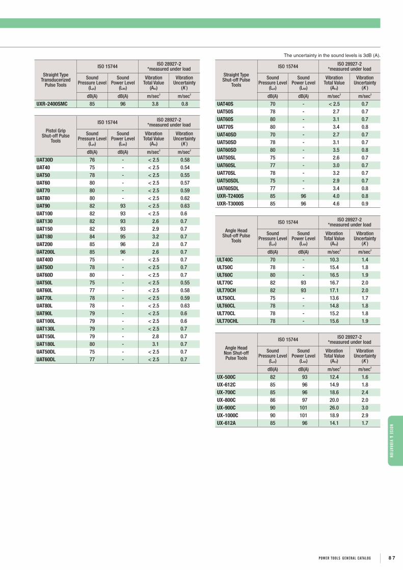
Straight Type Transducerized
Pulse Tools
ISO 15744 ISO 28927-2*measured under load
SoundPressure Level
(LpA)
SoundPower Level
(LWA)
VibrationTotal Value
(Ahd)
VibrationUncertainty
(K )
dB(A) dB(A) m/sec2 m/sec2
UXR-2400SMC 85 96 3.8 0.8
Pistol Grip Shut-off Pulse
Tools
ISO 15744 ISO 28927-2*measured under load
SoundPressure Level
(LpA)
SoundPower Level
(LWA)
VibrationTotal Value
(Ahd)
VibrationUncertainty
(K )
dB(A) dB(A) m/sec2 m/sec2
UAT30D 76 - < 2.5 0.58UAT40 75 - < 2.5 0.54UAT50 78 - < 2.5 0.55UAT60 80 - < 2.5 0.57UAT70 80 - < 2.5 0.59UAT80 80 - < 2.5 0.62UAT90 82 93 < 2.5 0.63UAT100 82 93 < 2.5 0.6UAT130 82 93 2.6 0.7UAT150 82 93 2.9 0.7UAT180 84 95 3.2 0.7UAT200 85 96 2.8 0.7UAT200L 85 96 2.6 0.7UAT40D 75 - < 2.5 0.7UAT50D 78 - < 2.5 0.7UAT60D 80 - < 2.5 0.7UAT50L 75 - < 2.5 0.55UAT60L 77 - < 2.5 0.58UAT70L 78 - < 2.5 0.59UAT80L 78 - < 2.5 0.63UAT90L 79 - < 2.5 0.6UAT100L 79 - < 2.5 0.6UAT130L 79 - < 2.5 0.7UAT150L 79 - 2.8 0.7UAT180L 80 - 3.1 0.7UAT50DL 75 - < 2.5 0.7UAT60DL 77 - < 2.5 0.7
Straight Type Shut-off Pulse
Tools
ISO 15744 ISO 28927-2*measured under load
SoundPressure Level
(LpA)
SoundPower Level
(LWA)
VibrationTotal Value
(Ahd)
VibrationUncertainty
(K )
dB(A) dB(A) m/sec2 m/sec2
UAT40S 70 - < 2.5 0.7UAT50S 78 - 2.7 0.7UAT60S 80 - 3.1 0.7UAT70S 80 - 3.4 0.8UAT40SD 70 - 2.7 0.7UAT50SD 78 - 3.1 0.7UAT60SD 80 - 3.5 0.8UAT50SL 75 - 2.6 0.7UAT60SL 77 - 3.0 0.7UAT70SL 78 - 3.2 0.7UAT50SDL 75 - 2.9 0.7UAT60SDL 77 - 3.4 0.8UXR-T2400S 85 96 4.0 0.8UXR-T3000S 85 96 4.6 0.9
Angle Head Shut-off Pulse
Tools
ISO 15744 ISO 28927-2*measured under load
SoundPressure Level
(LpA)
SoundPower Level
(LWA)
VibrationTotal Value
(Ahd)
VibrationUncertainty
(K )
dB(A) dB(A) m/sec2 m/sec2
ULT40C 70 - 10.3 1.4ULT50C 78 - 15.4 1.8ULT60C 80 - 16.5 1.9ULT70C 82 93 16.7 2.0ULT70CH 82 93 17.1 2.0ULT50CL 75 - 13.6 1.7ULT60CL 78 - 14.8 1.8ULT70CL 78 - 15.2 1.8ULT70CHL 78 - 15.6 1.9
Angle Head Non Shut-off Pulse Tools
ISO 15744 ISO 28927-2*measured under load
SoundPressure Level
(LpA)
SoundPower Level
(LWA)
VibrationTotal Value
(Ahd)
VibrationUncertainty
(K )
dB(A) dB(A) m/sec2 m/sec2
UX-500C 82 93 12.4 1.6UX-612C 85 96 14.9 1.8UX-700C 85 96 18.6 2.4UX-800C 86 97 20.0 2.0UX-900C 90 101 26.0 3.0UX-1000C 90 101 18.9 2.9UX-612A 85 96 14.1 1.7
The uncertainty in the sound levels is 3dB (A).
nOISE & VIBRaTIOnnOISE & VIBRaTIOn
NOISE LEVELS AND VIBRATION VALUESDECLARATION OF NOISE & VIBRATION EMISSION
8 7POWER TOOLS gEnERaL caTaLOg

Pistol Grip Non Shut-off Pulse Tools
ISO 15744 ISO 28927-2*measured under load
SoundPressure Level
(LpA)
SoundPower Level
(LWA)
VibrationTotal Value
(Ahd)
VibrationUncertainty
(K )
dB(A) dB(A) m/sec2 m/sec2
UL30 75 - < 2.5 0.56UL30D 75 - < 2.5 0.57UL40 75 - < 2.5 0.57UL40D 75 - < 2.5 0.58UL50 78 - < 2.5 0.59UL50D 78 - < 2.5 0.62UL60 80 - < 2.5 0.60UL60D 80 - < 2.5 0.7UL70 80 - < 2.5 0.60UL80 80 - < 2.5 0.60UL90 82 93 < 2.5 0.6UL100 80 - < 2.5 0.6UL130 83 94 2.7 0.7UL150 84 95 3.0 0.7
Straight Type Non Shut-off Pulse Tools
ISO 15744 ISO 28927-2*measured under load
SoundPressure Level
(LpA)
SoundPower Level
(LWA)
VibrationTotal Value
(Ahd)
VibrationUncertainty
(K )
dB(A) dB(A) m/sec2 m/sec2
UL30S 72 - < 2.5 0.7UL30SD 75 - 2.5 0.7UL40S 72 - 2.9 0.7UL40SD 75 - 3.0 0.7UL50S 78 - 3.3 0.8UL50SD 78 - 3.2 0.7UL60S 80 - 3.5 0.8UL60SD 80 - 3.7 0.8UL70S 84 95 3.7 0.8
Pistol Grip Non Shut-Off Pulse Tools
ISO 15744 ISO 28927-2*measured under load
SoundPressure Level
(LpA)
SoundPower Level
(LWA)
VibrationTotal Value
(Ahd)
VibrationUncertainty
(K )
dB(A) dB(A) m/sec2 m/sec2
U-350D 74 - < 2.5 0.53UXR-1820 84 95 2.7 0.7UXR-2000 85 96 2.6 0.7
Straight Type Non Shut-Off Pulse Tools
ISO 15744 ISO 28927-2*measured under load
SoundPressure Level
(LpA)
SoundPower Level
(LWA)
VibrationTotal Value
(Ahd)
VibrationUncertainty
(K )
dB(A) dB(A) m/sec2 m/sec2
U-310SD 74 - < 2.5 0.57
U-350SD 74 - < 2.5 0.58UX-900S 75 - < 2.5 0.6UX-1000S 75 - 2.8 0.7UX-1300S 77 - 2.9 0.7UXR-2000S 85 96 3.2 0.7UXR-2400S 85 96 4.1 0.8UXR-3000S 85 96 4.7 0.9
Stud BoltNon Shut-off Pulse Tools
ISO 15744 ISO 28927-2*measured under load
SoundPressure Level
(LpA)
SoundPower Level
(LWA)
VibrationTotal Value
(Ahd)
VibrationUncertainty
(K )
dB(A) dB(A) m/sec2 m/sec2
UX-ST800 75 - < 2.5 0.54UX-ST1000 75 - < 2.5 0.56
The uncertainty in the sound levels is 3dB (A).
nOIS
E &
VIBR
aTIO
nnO
ISE
& VI
BRaT
IOn
NOISE LEVELS AND VIBRATION VALUESDECLARATION OF NOISE & VIBRATION EMISSION
8 8 POWER TOOLS gEnERaL caTaLOg

The uncertainty in the sound levels is 3dB (A).
Pistol Grip Impact Wrenches
ISO 15744 ISO 28927-2*measured under load
SoundPressure Level (LpA)
SoundPower Level
(LWA)
VibrationTotal Value
(Ahd)
VibrationUncertainty
(K )
dB(A) dB(A) m/sec2 m/sec2
UW-6SLRK 91 102 3.8 0.8 UW-6SHBRK 92 103 4.3 0.8 UW-B6SLK 92 103 4.2 0.8UW-6SLRDK 91 102 4.1 0.8 UW-6SHBRDK 91 102 4.6 0.9 UW-B6SLDK 92 103 4.8 0.9
Straight Type Impact Wrenches
ISO 15744 ISO 28927-2*measured under load
SoundPressure Level
(LpA)
SoundPower Level
(LWA)
VibrationTotal Value
(Ahd)
VibrationUncertainty
(K )
dB(A) dB(A) m/sec2 m/sec2
UW-6SSLRK 90 101 5.3 0.9 UW-6SSRK 90 101 5.0 0.9 UW-6SSHRK 91 102 6.7 1.1 UW-6SSLRDK 90 101 6.0 1.0 UW-6SSRDK 90 101 6.1 1.0 UW-6SSHRDK 91 102 7.0 1.1
Angle Head Impact Wrenches
ISO 15744 ISO 28927-2*measured under load
SoundPressure Level (LpA)
SoundPower Level
(LWA)
VibrationTotal Value
(Ahd)
VibrationUncertainty
(K )
dB(A) dB(A) m/sec2 m/sec2
UW-6CSLRK 93 104 18.4 2.1 UW-6CSRK 94 105 18.0 2.1 UW-6CSHRK 94 105 27.0 3.0 UW-6ASLRK 92 103 17.8 2.0
Pistol Grip Impact Wrenches
ISO 15744 ISO 28927-2*measured under load
SoundPressure Level
(LpA)
SoundPower Level
(LWA)
VibrationTotal Value
(Ahd)
VibrationUncertainty
(K )
dB(A) dB(A) m/sec2 m/sec2
UW-61ERK 91 102 4.0 0.8 UW-101ERK 96 107 5.8 1.0UW-131ERK 97 108 7.6 1.1 UW-161ER 96 107 6.3 1.0 UW-8SHRK 93 104 5.6 1.0 UW-9SRK 93 104 5.1 0.9 UW-10SHRK 95 106 5.8 1.0UW-13SRK 95 106 7.7 1.1
Straight Type Impact Wrenches
ISO 15744 ISO 28927-2*measured under load
SoundPressure Level
(LpA)
SoundPower Level
(LWA)
VibrationTotal Value
(Ahd)
VibrationUncertainty
(K )
dB(A) dB(A) m/sec2 m/sec2
UW-9SSRK 95 106 10.7 1.4UW-13SSK 97 108 12.7 1.6
Angle Head Impact Wrenches
ISO 15744 ISO 28927-2*measured under load
SoundPressure Level
(LpA)
SoundPower Level
(LWA)
VibrationTotal Value
(Ahd)
VibrationUncertainty
(K )
dB(A) dB(A) m/sec2 m/sec2
UW-9CSRK 95 106 33 3UW-13CSK 97 108 35 4
nOISE & VIBRaTIOnnOISE & VIBRaTIOn
NOISE LEVELS AND VIBRATION VALUESDECLARATION OF NOISE & VIBRATION EMISSION
8 9POWER TOOLS gEnERaL caTaLOg

The uncertainty in the sound levels is 3dB (A).
Pistol Grip Impact Wrenches
ISO 15744 ISO 28927-2*measured under load
SoundPressure Level
(LpA)
SoundPower Level
(LWA)
VibrationTotal Value
(Ahd)
VibrationUncertainty
(K )
dB(A) dB(A) m/sec2 m/sec2
UW-140P 93 104 6.3 1.0 UW-140PR 93 104 6.6 1.0UW-140PL 93 104 6.4 1.0 UW-140PRL 93 104 6.7 1.0 UW-220P 95 106 5.6 1.0UW-220PL 95 106 5.7 1.0 UW-251P 95 106 5.7 1.0 UW-251PL 95 106 5.8 1.0 UW-O22S(SHORT) 103 114 6.0 1.0 UW-O22S(LONG) 103 114 5.7 1.0 UW-O32S(SHORT) 109 120 6.2 1.0 UW-O32S(LONG) 109 120 5.9 1.0 UW-381P 99 110 6.2 1.0UW-381PL 99 110 6.0 1.0
Straight Type Impact Wrenches
ISO 15744 ISO 28927-2*measured under load
SoundPressure Level
(LpA)
SoundPower Level
(LWA)
VibrationTotal Value
(Ahd)
VibrationUncertainty
(K )
dB(A) dB(A) m/sec2 m/sec2
UW-22S(IN) 103 114 6.5 1.0 UW-22S(SHORT) 103 114 6.6 1.0 UW-22S(LONG) 103 114 6.3 1.0 UW-32SLA(SHORT) 109 120 6.2 1.0 UW-32SLA(LONG) 109 120 5.9 1.0 UW-381 100 111 7.6 1.1 UW-381L 100 111 7.5 1.1 UW-401(SHORT) 110 121 8.9 1.3 UW-401L 110 121 9.0 1.3
Stud Bolt Impact Wrenches
ISO 15744 ISO 28927-2*measured under load
SoundPressure Level
(LpA)
SoundPower Level
(LWA)
VibrationTotal Value
(Ahd)
VibrationUncertainty
(K )
dB(A) dB(A) m/sec2 m/sec2
UW-ST6SHK 92 103 4.1 0.8 UW-ST9SK 97 108 4.9 0.9 UW-ST10SHK 97 108 5.8 1.0UW-ST6SSHK 92 103 6.6 1.0
Ratchet Wrenches
ISO 15744 ISO 28927-2*measured under load
SoundPressure Level
(LpA)
SoundPower Level
(LWA)
VibrationTotal Value
(Ahd)
VibrationUncertainty
(K )
dB(A) dB(A) m/sec2 m/sec2
URW-6 81 92 3.2 0.7 URW-60 85 96 3.4 0.8 URW-60R 85 96 3.4 0.8 URW-8N 90 101 3.2 0.7 URW-80 93 104 4.0 0.8 URW-80R 93 104 4.0 0.8 URW-81 93 104 4.0 0.8 URW-81R 93 104 4.0 0.8 URW-8 86 97 3.3 0.8 URW-9N 90 101 3.3 0.7 URW-10N 90 101 3.3 0.8 URW-12N 91 102 3.6 0.8 URW-12NA 91 102 3.6 0.8 URW-12NB 91 102 4.1 0.8
Open-Ended Wrenches
ISO 15744 ISO 28927-2 *measured at free running
SoundPressure Level
(LpA)
SoundPower Level
(LWA)
VibrationTotal Value
(Ahd)
VibrationUncertainty
(K )
dB(A) dB(A) m/sec2 m/sec2
UOW-11-10 76 - < 2.5 0.47UOW-11-14 76 - < 2.5 0.47UOW-11-22 76 - < 2.5 0.47UOW-11-30 76 - < 2.5 0.47UOW-T60-10 76 - < 2.5 0.47UOW-T60-14 76 - < 2.5 0.47UOW-T60-22 76 - < 2.5 0.47UOW-T60-30 76 - < 2.5 0.48
Geared Wrenches
ISO 15744 ISO 28927-2 *measured at free running
SoundPressure Level
(LpA)
SoundPower Level
(LWA)
VibrationTotal Value
(Ahd)
VibrationUncertainty
(K )
dB(A) dB(A) m/sec2 m/sec2
UGW-6N 76 - < 2.5 0.48UGW-8N 76 - < 2.5 0.48
nOIS
E &
VIBR
aTIO
nnO
ISE
& VI
BRaT
IOn
NOISE LEVELS AND VIBRATION VALUESDECLARATION OF NOISE & VIBRATION EMISSION
9 0 POWER TOOLS gEnERaL caTaLOg

The uncertainty in the sound levels is 3dB (A).
Angle Nutrunners
ISO 15744 ISO 28927-2 *measured at free running
SoundPressure Level
(LpA)
SoundPower Level
(LWA)
VibrationTotal Value
(Ahd)
VibrationUncertainty
(K )
dB(A) dB(A) m/sec2 m/sec2
UAN-611R-60C 80 - < 2.5 0.48UAN-611R-50C 80 - < 2.5 0.48UAN-611R-40C 80 - < 2.5 0.48UAN-611R-30C 80 - < 2.5 0.48UAN-701R-60C 85 96 < 2.5 0.51UAN-701R-40C 85 96 < 2.5 0.50UAN-701R-30C 85 96 < 2.5 0.50UAN-611RM-60C 80 - < 2.5 0.49UAN-611RM-50C 80 - < 2.5 0.48UAN-611RM-40C 80 - < 2.5 0.48UAN-611RM-30C 80 - < 2.5 0.48UAN-701RM-60C 85 96 < 2.5 0.51UAN-701RM-40C 85 96 < 2.5 0.50UAN-701RM-30C 85 96 < 2.5 0.50
Straight Screwdrivers
ISO 15744 ISO 28927-2 *measured at free running
SoundPressure Level
(LpA)
SoundPower Level
(LWA)
VibrationTotal Value
(Ahd)
VibrationUncertainty
(K )
dB(A) dB(A) m/sec2 m/sec2
US-LT10B 75 - < 2.5 0.48US-LT20A(B)-26 71 - < 2.5 0.48 US-LT20A(B)-18 70 - < 2.5 0.48 US-LT20A(B)-10 70 - < 2.5 0.48 US-LT30A(B)-23 71 - < 2.5 0.48 US-LT30A(B)-17 70 - < 2.5 0.48 US-LT30A(B)-11 70 - < 2.5 0.48 US-LT40A(B)-21 74 - < 2.5 0.48 US-LT40A(B)-15 70 - < 2.5 0.48 US-LT40A(B)-08 70 - < 2.5 0.48 US-LT50B-17 75 - < 2.5 0.48 US-LT50B-08 75 - < 2.5 0.48US-LT50B-05 74 - < 2.5 0.49 US-LT30A(B)L-23 71 - < 2.5 0.48 US-LT30A(B)L-17 70 - < 2.5 0.48 US-LT30A(B)L-11 70 - < 2.5 0.48 US-LT40BL-21 74 - < 2.5 0.48 US-LT40A(B)L-15 70 - < 2.5 0.48 US-LT40BL-08 70 - < 2.5 0.48
Pistol Grip Screwdrivers
ISO 15744 ISO 28927-2 *measured at free running
SoundPressure Level
(LpA)
SoundPower Level
(LWA)
VibrationTotal Value
(Ahd)
VibrationUncertainty
(K )
dB(A) dB(A) m/sec2 m/sec2
US-LT31PB-23 70 - < 2.5 0.48 US-LT31PB-17 70 - < 2.5 0.48 US-LT31PB-11 70 - < 2.5 0.48 US-LT31PB-05 70 - < 2.5 0.48 US-LT41PB-21 74 - < 2.5 0.48 US-LT41PB-15 70 - < 2.5 0.48US-LT41PB-08 70 - < 2.5 0.48 US-LT51PB-17 75 - < 2.5 0.48 US-LT51PB-08 75 - < 2.5 0.48 US-LT51PB-05 74 - < 2.5 0.49 US-LT60P-11 77 - < 2.5 0.48 US-LT60P-07 76 - < 2.5 0.49 US-LT60P-03 75 - < 2.5 0.49
Angle Head Screwdrivers
ISO 15744 ISO 28927-2 *measured at free running
SoundPressure Level
(LpA)
SoundPower Level
(LWA)
VibrationTotal Value
(Ahd)
VibrationUncertainty
(K )
dB(A) dB(A) m/sec2 m/sec2
US-LT30B-17C 73 - < 2.5 0.48 US-LT30B-11C 73 - < 2.5 0.48 US-LT40B-15C 75 - < 2.5 0.48 US-LT40B-08C 75 - < 2.5 0.48 US-LT40B-05C 75 - < 2.5 0.48 US-LT40-08C(P) 75 - < 2.5 0.48 US-LT40-05C(P) 75 - < 2.5 0.48 US-LT40-03C(P) 72 - < 2.5 0.48
Screwdrivers
ISO 15744 ISO 28927-2 *measured at free running
SoundPressure Level
(LpA)
SoundPower Level
(LWA)
VibrationTotal Value
(Ahd)
VibrationUncertainty
(K )
dB(A) dB(A) m/sec2 m/sec2
US-3.5A 75 - < 2.5 0.48 US-3.5B 75 - < 2.5 0.48 US-4 75 - < 2.5 0.48 US-5 75 - < 2.5 0.48 US-3.5MA 75 - < 2.5 0.48 US-40 70 - < 2.5 0.48 US-50 76 - < 2.5 0.48 US-3.5PB 75 - < 2.5 0.48 US-4PB 75 - < 2.5 0.48 US-5PB 75 - < 2.5 0.48 US-4CA 85 96 < 2.5 0.48 US-5CA 85 96 < 2.5 0.48
nOISE & VIBRaTIOnnOISE & VIBRaTIOn
NOISE LEVELS AND VIBRATION VALUESDECLARATION OF NOISE & VIBRATION EMISSION
9 1POWER TOOLS gEnERaL caTaLOg
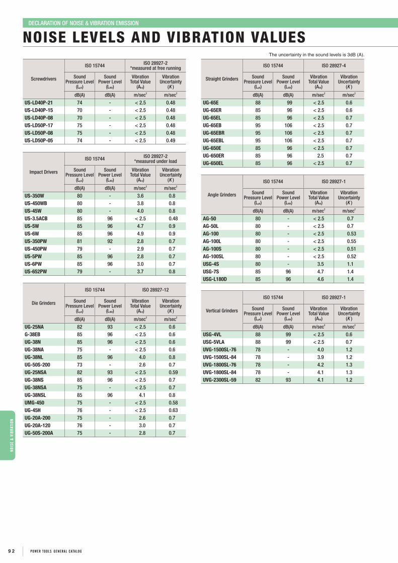
The uncertainty in the sound levels is 3dB (A).
Screwdrivers
ISO 15744 ISO 28927-2 *measured at free running
SoundPressure Level
(LpA)
SoundPower Level
(LWA)
VibrationTotal Value
(Ahd)
VibrationUncertainty
(K )
dB(A) dB(A) m/sec2 m/sec2
US-LD40P-21 74 - < 2.5 0.48 US-LD40P-15 70 - < 2.5 0.48 US-LD40P-08 70 - < 2.5 0.48 US-LD50P-17 75 - < 2.5 0.48 US-LD50P-08 75 - < 2.5 0.48 US-LD50P-05 74 - < 2.5 0.49
Impact Drivers
ISO 15744 ISO 28927-2 *measured under load
SoundPressure Level
(LpA)
SoundPower Level
(LWA)
VibrationTotal Value
(Ahd)
VibrationUncertainty
(K )
dB(A) dB(A) m/sec2 m/sec2
US-350W 80 - 3.6 0.8US-450WB 80 - 3.8 0.8US-45W 80 - 4.0 0.8US-3.5ACB 85 96 < 2.5 0.48 US-5W 85 96 4.7 0.9 US-6W 85 96 4.9 0.9 US-350PW 81 92 2.8 0.7 US-450PW 79 - 2.9 0.7 US-5PW 85 96 2.8 0.7 US-6PW 85 96 3.0 0.7 US-652PW 79 - 3.7 0.8
Die Grinders
ISO 15744 ISO 28927-12
SoundPressure Level
(LpA)
SoundPower Level
(LWA)
VibrationTotal Value
(Ahd)
VibrationUncertainty
(K )
dB(A) dB(A) m/sec2 m/sec2
UG-25NA 82 93 < 2.5 0.6 G-38EB 85 96 < 2.5 0.6 UG-38N 85 96 < 2.5 0.6 UG-38NA 75 - < 2.5 0.6 UG-38NL 85 96 4.0 0.8 UG-50S-200 73 - 2.6 0.7 UG-25NSA 82 93 < 2.5 0.59UG-38NS 85 96 < 2.5 0.7UG-38NSA 75 - < 2.5 0.7 UG-38NSL 85 96 4.1 0.8 UMG-450 75 - < 2.5 0.58 UG-45H 76 - < 2.5 0.63 UG-20A-200 75 - 2.6 0.7 UG-20A-120 76 - 3.0 0.7 UG-50S-200A 75 - 2.8 0.7
Straight Grinders
ISO 15744 ISO 28927-4
SoundPressure Level
(LpA)
SoundPower Level
(LWA)
VibrationTotal Value
(Ahd)
VibrationUncertainty
(K )
dB(A) dB(A) m/sec2 m/sec2
UG-65E 88 99 < 2.5 0.6 UG-65ER 85 96 < 2.5 0.6UG-65EL 85 96 < 2.5 0.7 UG-65EB 95 106 < 2.5 0.7 UG-65EBR 95 106 < 2.5 0.7 UG-65EBL 95 106 < 2.5 0.7 UG-650E 85 96 < 2.5 0.7 UG-650ER 85 96 2.5 0.7UG-650EL 85 96 < 2.5 0.7
Angle Grinders
ISO 15744 ISO 28927-1
SoundPressure Level
(LpA)
SoundPower Level
(LWA)
VibrationTotal Value
(Ahd)
VibrationUncertainty
(K )
dB(A) dB(A) m/sec2 m/sec2
AG-50 80 - < 2.5 0.7AG-50L 80 - < 2.5 0.7AG-100 80 - < 2.5 0.53AG-100L 80 - < 2.5 0.55AG-100S 80 - < 2.5 0.51AG-100SL 80 - < 2.5 0.52USG-4S 80 - 3.5 1.1 USG-7S 85 96 4.7 1.4 USG-L180D 85 96 4.6 1.4
Vertical Grinders
ISO 15744 ISO 28927-1
SoundPressure Level
(LpA)
SoundPower Level
(LWA)
VibrationTotal Value
(Ahd)
VibrationUncertainty
(K )
dB(A) dB(A) m/sec2 m/sec2
USG-4VL 88 99 < 2.5 0.6 USG-5VLA 88 99 < 2.5 0.7 UVG-1500SL-76 78 - 4.0 1.2 UVG-1500SL-84 78 - 3.9 1.2 UVG-1800SL-76 78 - 4.2 1.3 UVG-1800SL-84 78 - 4.1 1.3 UVG-2300SL-59 82 93 4.1 1.2
nOIS
E &
VIBR
aTIO
nnO
ISE
& VI
BRaT
IOn
NOISE LEVELS AND VIBRATION VALUESDECLARATION OF NOISE & VIBRATION EMISSION
9 2 POWER TOOLS gEnERaL caTaLOg

The uncertainty in the sound levels is 3dB (A).
Angle Grinders
ISO 15744 ISO 28927-1
SoundPressure Level
(LpA)
SoundPower Level
(LWA)
VibrationTotal Value
(Ahd)
VibrationUncertainty
(K )
dB(A) dB(A) m/sec2 m/sec2
UAG-40SB-136 84 95 4.1 1.2UAG-40SBL-136 84 95 4.1 1.3 UAG-40SC-136 84 95 4.1 1.3 UAG-40SCL-136 84 95 4.1 1.3 UAG-50SBL-120 82 93 4.1 1.2UAG-50SCL-120 82 93 4.1 1.2UAG-50SC-120 82 93 4.0 1.2UAG-50SB-109 82 93 4.0 1.2UAG-50SBL-109 82 93 4.0 1.2UAG-70SBL-76 83 94 5.2 1.6 UAG-70SB-76 83 94 5.2 1.6 UAG-70SC-76 83 94 5.2 1.6 UAG-70SCL-76 83 94 5.2 1.6 UAG-90SBL-59 88 99 6.0 1.8
Straight Grinders
ISO 15744 ISO 28927-4
SoundPressure Level
(LpA)
SoundPower Level
(LWA)
VibrationTotal Value
(Ahd)
VibrationUncertainty
(K )
dB(A) dB(A) m/sec2 m/sec2
UG-1250-72 88 99 < 2.5 0.7 UG-1250L-72 88 99 < 2.5 0.7 UG-1500-60 88 99 < 2.5 0.48UG-1500-41 88 99 < 2.5 0.44UG-1500L-60 88 99 < 2.5 0.45UG-1500L-41 88 99 < 2.5 0.41
Sanders &
Polishers
ISO 15744 ISO 28927-3
SoundPressure Level
(LpA)
SoundPower Level
(LWA)
VibrationTotal Value
(Ahd)
VibrationUncertainty
(K )
dB(A) dB(A) m/sec2 m/sec2
USG-45P 81 92 < 2.5 0.63 AG-180W 86 97 < 2.5 0.7UP-80-15 82 93 < 2.5 0.55 UP-80-40 84 95 < 2.5 0.56 UP-80-60 85 96 < 2.5 0.57 UP-15 87 98 6.3 1.0 UP-25DB 73 - 5.5 0.9 UP-26DB 74 - 5.8 0.9 UP-15N 94 105 6.4 1.0 UP-25NB 97 108 5.9 0.9 UP-26NB 98 109 6.0 1.0
Pistol-Grip Drills
ISO 15744 ISO 28927-5
SoundPressure Level
(LpA)
SoundPower Level
(LWA)
VibrationTotal Value
(Ahd)
VibrationUncertainty
(K )
dB(A) dB(A) m/sec2 m/sec2
UD-50-200 73 - < 2.5 0.61UD-50-45 72 - < 2.5 0.58UD-50-22 72 - < 2.5 0.59UD-60-29 77 - < 2.5 0.61UD-60-20 77 - < 2.5 0.60UD-60-15 76 - < 2.5 0.57UD-60-07 75 - < 2.5 0.58UD-60-04 75 - < 2.5 0.57UD-80-12 79 - < 2.5 0.60UD-80-07 79 - < 2.5 0.6UD-80-04 79 - < 2.5 0.62
Straight Drills
ISO 15744 ISO 28927-5
SoundPressure Level
(LpA)
SoundPower Level
(LWA)
VibrationTotal Value
(Ahd)
VibrationUncertainty
(K )
dB(A) dB(A) m/sec2 m/sec2
UD-50S-200 78 - < 2.5 0.6UD-50S-45 77 - < 2.5 0.61UD-50S-22 77 - < 2.5 0.61UD-60S-29 77 - < 2.5 0.6UD-60S-20 77 - < 2.5 0.68UD-60S-15 77 - < 2.5 0.67UD-60S-07 75 - < 2.5 0.63UD-60S-04 75 - < 2.5 0.63UD-80S-12 79 - < 2.5 0.6UD-80S-07 79 - < 2.5 0.6UD-80S-04 79 - < 2.5 0.6UD-80-12G 79 - < 2.5 0.65UD-80-07G 79 - < 2.5 0.65UD-80-04G 79 - < 2.5 0.63
Angle Head Drills
ISO 15744 ISO 28927-5
SoundPressure Level
(LpA)
SoundPower Level
(LWA)
VibrationTotal Value
(Ahd)
VibrationUncertainty
(K )
dB(A) dB(A) m/sec2 m/sec2
UD-50S-45A 79 - < 2.5 0.68UD-50S-22A 79 - < 2.5 0.67UD-60S-29C 79 - < 2.5 0.7UD-60S-15C 79 - < 2.5 0.69
Heavy Duty Drill
ISO 15744 ISO 28927-10
SoundPressure Level
(LpA)
SoundPower Level
(LWA)
VibrationTotal Value
(Ahd)
VibrationUncertainty
(K )
dB(A) dB(A) m/sec2 m/sec2
URD-22RR 95 106 < 2.5 0.7
nOISE & VIBRaTIOnnOISE & VIBRaTIOn
NOISE LEVELS AND VIBRATION VALUESDECLARATION OF NOISE & VIBRATION EMISSION
9 3POWER TOOLS gEnERaL caTaLOg

The uncertainty in the sound levels is 3dB (A).
Tappers
ISO 15744 ISO 20643
SoundPressure Level
(LpA)
SoundPower Level
(LWA)
VibrationTotal Value
(Ahd)
VibrationUncertainty
(K )
dB(A) dB(A) m/sec2 m/sec2
UT-66B-15 85 96 < 2.5 0.61UT-66B-07 85 96 < 2.5 0.61UT-60-07 75 - < 2.5 0.69UT-60-04 75 - < 2.5 0.59UT-60S-07 75 - < 2.5 0.59UT-60S-04 75 - < 2.5 0.56
Pistol/Straight Super Vibration-Proof Riveting
Hammers
ISO 15744 ISO 28927-10
SoundPressure Level
(LpA)
SoundPower Level
(LWA)
VibrationTotal Value
(Ahd)
VibrationUncertainty
(K )
dB(A) dB(A) m/sec2 m/sec2
BRH-1UD (R, H) 89 100 <2.5 0.9BRH-1USD (R, H) 89 100 <2.5 0.9BRH-5UD (R, H) 89 100 <2.5 0.9BRH-5USD (R, H) 89 100 <2.5 0.9
Pistol/Straight Type
Riveting Hammers
ISO 15744 ISO 28927-10
SoundPressure Level
(LpA)
SoundPower Level
(LWA)
VibrationTotal Value
(Ahd)
VibrationUncertainty
(K )
dB(A) dB(A) m/sec2 m/sec2
SBH-0 90 101 < 2.5 0.6SBH-1A (R, H) 92 103 4.5 0.9BRH-1U (R, H) 95 106 7.8 1.1BRH-1US (R, H) 95 106 7.5 1.1BRH-1UG (R, H) 95 106 7.5 1.1BRH-5U (R, H) 95 106 7.6 1.1BRH-5US (R, H) 95 106 7.4 1.1BRH-5UG (R, H) 95 106 7.3 1.1
Impact Cutters &
Flux Chippers
ISO 15744 ISO 28927-10
SoundPressure Level
(LpA)
SoundPower Level
(LWA)
VibrationTotal Value
(Ahd)
VibrationUncertainty
(K )
dB(A) dB(A) m/sec2 m/sec2
BRH-7 (R, H) 100 111 7.5 1.1UFC-0N 90 101 6.0 1.0UFC-1N 90 101 5.9 1.0
Chipping &
Caulking Hammers
ISO 15744 ISO 28927-10
SoundPressure Level
(LpA)
SoundPower Level
(LWA)
VibrationTotal Value
(Ahd)
VibrationUncertainty
(K )
dB(A) dB(A) m/sec2 m/sec2
AA-00 (R, H) 95 106 5.0 0.9AA-20 (R, H) 100 111 5.6 1.0AA-30 (R, H) 100 111 6.0 1.0AA-40 (R, H) 100 111 6.3 1.0PB-20 (R, H) 100 111 6.6 1.0PB-30 (R, H) 100 111 7.1 1.1
nOIS
E &
VIBR
aTIO
n
NOISE LEVELS AND VIBRATION VALUESDECLARATION OF NOISE & VIBRATION EMISSION
9 4 POWER TOOLS gEnERaL caTaLOg

9 5POWER TOOLS gEnERaL caTaLOg
INDIVIDUAL CATALOG SHEETS AND PARTS LISTS ARE AVAILABLE FOR FURTHER INFORMATION.
TORQUE Unit to beconverted Nm kgf.cm kgf.m in.Ibs ft.Ibs
1Nm - 10.2 0.102 8.8 0.74
1kgf.cm 0.098 - 0.01 0.868 0.072
1kgf.m 9.8 100 - 86.8 7.2
1in.Ibs 0.114 1.152 1.16×10⁻² - 8.3×10⁻²
1ft.Ibs 1.36 13.83 0.138 12 -
PRESSURE Unit to beconverted MPa Bar kgf/cm2 psi
MPa 1 10 10.2 1.44×10²
Bar 10 1 1.02 14.4
kgf/cm2 9.8×10⁻² 0.98 1 14.1
psi 6.9×10⁻² 6.9×10⁻² 7.1×10⁻² 1
HORSE POWER Unit to beconverted kw kgf m/s PS HP
kw 1 1.02×10² 1.36 1.34
kgf m/s 9.8×10⁻⁵ 1 1.33×10⁻² 1.32×10⁻²
PS 0.74 75 1 0.99
HP 0.75 76 1.01 1
LENGTH
Unit to beconverted m in ft
m 1 39 3.3
in 2.54×10⁻² 1 8.3×10⁻²
ft 0.31 12.0 1
WEIGHT Unit to beconverted kg Ibs
kg 1 2.2
Ibs 0.45 1
FLOW Unit to beconverted m3/s m3/min I/s ft3/s
m3/s 1 60 1.00×10³ 35
m3/min 1.67×10⁻² 1 17 0.59
I/s 1.00×10⁻³ 6.0×10⁻² 1 3.5×10⁻²
ft3/s 2.8×10⁻² 1.7 28 1
(CONVERSION TABLE)

INDEX � Model names of models listed in this catalog are listed in ABC order.
AA-00(R,H) 71
AA-20(R,H) 71
AA-30(R,H) 71
AA-40(R,H) 71
AG-50(OUT) 56
AG-50L(OUT) 56
AG-100(IN) 56
AG-100(OUT) 56
AG-100L(IN) 56
AG-100L(OUT) 56
AG-100S(IN) 56
AG-100S(OUT) 56
AG-100SL(IN) 56
AG-100SL(OUT) 56
AG-180W 60
BP-T40 12
BP-T40(RF8) 13
BP-T40(TK) 14
BP-T40(Z) 13
BP-T40D 12
BP-T40D(RF8) 13
BP-T40D(TK) 14
BP-T40D(Z) 13
BP-T50 12
BP-T50(RF8) 13
BP-T50(TK) 14
BP-T50(Z) 13
BP-T50D 12
BP-T50D(RF8) 13
BP-T50D(TK) 14
BP-T50D(Z) 13
BP-T60 12
BP-T60(RF8) 13
BP-T60(TK) 14
BP-T60(Z) 13
BP-T60D 12
BP-T60D(RF8) 13
BP-T60D(TK) 14
BP-T60D(Z) 13
BRH-1U(R,H) 68
BRH-1UD(R,H) 68
BRH-1UG(R,H) 68
BRH-1US(R,H) 68
BRH-1USD(R,H) 68
BRH-5U(R,H) 68
BRH-5UD(R,H) 68
BRH-5UG(R,H) 68
BRH-5US(R,H) 68
BRH-5USD(R,H) 68
BRH-7(H) 70
BRH-7(R) 70
G-38EB 55
LR-09(B-90) 53
LR-09(B-200) 53
PB-20(R,H) 71
PB-30(R,H) 71
SBH-0 68
SBH-1A(R,H) 68
U-310SD 32
U-350D 32
U-350SD 32
UA40DMC 27
UA40MC 27
UA40SDMC 27
UA40SMC 27
UA50DMC 27
UA50MC 27
UA50SDMC 27
UA50SMC 27
UA60MC 27
UA60SDMC 27
UA60SMC 27
UA70MC 27
UA70SMC 27
UA80MC 27
UA90MC 27
UA100MC 27
UA130MC 27
UA150MC 27
UA400AMC 25
UA500AMC 25
UA600AMC 25
UA700AMC 25
UA800AMC 25
UA900AMC 25
UA1000AMC 25
UA1300AMC 25
UAG-40SB-136 58
UAG-40SBL-136 58
UAG-40SC-136 58
UAG-40SCL-136 58
UAG-50SB-109 58
UAG-50SBL-109 58
UAG-50SBL-120 58
UAG-50SC-120 58
UAG-50SCL-120 58
UAG-70SB-76 58
UAG-70SBL-76 58
UAG-70SC-76 58
UAG-70SCL-76 58
UAG-90SBL-59 58
UAN-611R-30C 35
UAN-611R-40C 35
UAN-611R-50C 35
UAN-611R-60C 35
UAN-611RM-30C 35
UAN-611RM-40C 35
UAN-611RM-50C 35
UAN-611RM-60C 35
UAN-701R-30C 35
UAN-701R-40C 35
UAN-701R-60C 35
UAN-701RM-30C 35
UAN-701RM-40C 35
UAN-701RM-60C 35
UAT30D 29
UAT30SD 29
UAT40 29
UAT40D 29
UAT40S 29
UAT40SD 29
UAT50 29
UAT50D 29
UAT50DL 29
UAT50L 29
UAT50S 29
UAT50SD 29
UAT50SDL 29
UAT50SL 29
UAT60 29
UAT60D 29
UAT60DL 29
UAT60L 29
UAT60S 29
UAT60SD 29
UAT60SDL 29
UAT60SL 29
UAT70 29
UAT70L 29
UAT70S 29
UAT70SL 29
UAT80 29
UAT80L 29
UAT90 29
UAT90L 29
UAT100 29
UAT100L 29
UAT130 29
UAT130L 29
UAT150 29
UAT150L 29
UAT180 29
UAT180L 29
UAT200 29
UAT200L 29
UD-50-22 64
UD-50-45 64
UD-50-200 64
UD-50S-22 64
UD-50S-22A 65
UD-50S-45 64
UD-50S-45A 65
UD-50S-200 64
UD-60-04 64
UD-60-07 64
UD-60-15 64
UD-60-20 64
UD-60-29 64
UD-60S-04 64
UD-60S-07 64
UD-60S-15 64
UD-60S-15C 65
UD-60S-20 64
UD-60S-29 64
UD-60S-29C 65
UD-80-04 64
UD-80-04G 64
UD-80-07 64
UD-80-07G 64
UD-80-12 64
UD-80-12G 64
UD-80S-04 64
UD-80S-07 64
UD-80S-12 64
UDBP-A50 15
UDBP-A50(P) 15
UDBP-A60 15
UDBP-A60(P) 15
UDBP-TA70(P) 15
UDBP-TA70(TK-P) 15
UDP-A100MC,(TL) 19
UDP-A120MC,(TL) 19
UDP-A600LMC,(TL) 19
UDP-A700MC,(TL) 19
UDT-25A/E 75
UDT-200A/E 74
UDT-500A/E 74
UEC-4800A/E(SD) 21
UEC-4800A/E(SD-ANGLE)21
UEC-4800TPA/E(SD)21
UEC-4800TPA/E(SD-ANGLE) 21
UEC-5500A/E 23
UECP-4810 18
UET-10CRA(115V) 76
UET-10CRE(230V) 76
UFC-0N 70
UFC-1N 70
UFT-6 77
UFT-10 77
UFT-16 77
UFT-24 77
UG-20A-120 55
UG-20A-200 55
UG-25NA 55
UG-25NSA 55
UG-38N 55
UG-38NA 55
UG-38NL 55
UG-38NS 55
UG-38NSA 55
UG-38NSL 55
UG-45H 55
UG-50S-200 55
UG-50S-200A 55
UG-65E 56
UG-65EB 56
UG-65EBL 56
UG-65EBR 56
UG-65EL 56
UG-65ER 56
UG-650E 56
UG-650EL 56
UG-650ER 56
UG-1250-72 59
UG-1250L-72 59
UG-1500-41 59
UG-1500-60 59
UG-1500L-41 59
UG-1500L-60 59
UGW-6N 34
UGW-8N 34
UHT-12 77
UHT-16 77
UHT-25 77
UHT-35 77
UHT-50 77
UL30 30
UL30D 30
UL30S 30
UL30SD 30
UL40 30
UL40D 30
UL40S 30
UL40SD 30
UL50 30
UL50D 30
UL50S 30
UL50SD 30
UL60 30
UL60D 30
UL60S 30
UL60SD 30
UL70 30
UL70S 30
UL80 30
UL90 30
UL100 30
UL130 30
UL150 30
ULT40C 31
ULT50C 31
ULT50CL 31
ULT60C 31
ULT60CL 31
ULT70C 31
ULT70CH 31
ULT70CHL 31
ULT70CL 31
UMG-450 55
UOW-11-10 34
UOW-11-14 34
UOW-11-22 34
UOW-11-30 34
UOW-T60-10 34
UOW-T60-14 34
UOW-T60-22 34
UOW-T60-30 34
UP-15 60
UP-15N 60
UP-25DB 60
UP-25NB 60
UP-26DB 60
UP-26NB 60
UP-80-15 60
UP-80-40 60
UP-80-60 60
URD-22RR 66
URW-6 33
URW-8 33
URW-8N 33
URW-9N 33
URW-10N 33
URW-12N 33
URW-12NA 33
URW-12NB 33
URW-60 33
URW-60R 33
URW-80 33
URW-80R 33
URW-81 33
URW-81R 33
US-3.5A 50
US-3.5ACB 50
US-3.5B 50
US-3.5MA 50
US-3.5PB 50
US-4 50
US-4CA 50
US-4PB 50
US-5 50
US-5CA 50
US-5PB 50
US-5PW 52
US-5W 52
US-6PW 52
US-6W 52
US-40 50
US-45W 52
US-50 50
US-350PW 52
US-350W 52
US-450PW 52
US-450WB 52
US-652PW 52
US-LD40P-08 51
US-LD40P-15 51
US-LD40P-21 51
US-LD50P-05 51
US-LD50P-08 51
US-LD50P-17 51
US-LT10B 48
US-LT20A-10 48
US-LT20A-18 48
US-LT20A-26 48
US-LT20B-10 48
US-LT20B-18 48
US-LT20B-26 48
US-LT30A-11 48
US-LT30A-17 48
US-LT30A-23 48
US-LT30AL-11 48
US-LT30AL-17 48
US-LT30AL-23 48
US-LT30B-11 48
US-LT30B-11C 49
US-LT30B-17 48
US-LT30B-17C 49
US-LT30B-23 48
US-LT30BL-11 48
US-LT30BL-17 48
US-LT30BL-23 48
US-LT31PB-05 49
US-LT31PB-11 49
US-LT31PB-17 49
US-LT31PB-23 49
US-LT40-03C(P) 49
US-LT40-05C(P) 49
US-LT40-08C(P) 49
US-LT40A-08 48
US-LT40A-15 48
US-LT40A-21 48
US-LT40AL-15 48
US-LT40B-05C 49
US-LT40B-08 48
US-LT40B-08C 49
US-LT40B-15 48
US-LT40B-15C 49
US-LT40B-21 48
US-LT40BL-08 48
US-LT40BL-15 48
US-LT40BL-21 48
US-LT41PB-08 49
US-LT41PB-15 49
US-LT41PB-21 49
US-LT50B-05 48
US-LT50B-08 48
US-LT50B-17 48
US-LT51PB-05 49
US-LT51PB-08 49
US-LT51PB-17 49
US-LT60P-03 49
US-LT60P-07 49
US-LT60P-11 49
USG-4S 56
USG-4VL 57
USG-5VLA 57
USG-7S 56
USG-45P 60
USG-L180D 56
UT-60-04 66
UT-60-07 66
UT-60S-04 66
UT-60S-07 66
UT-66B-07 66
UT-66B-15 66
UTM-1500A/E(CN) 42
UTM-1500A/E(PS) 42
UTM-1500A/E(RA-CN) 42
UTM-1500A/E(RA-PS) 42
UVG-1500SL-76 57
UVG-1500SL-84 57
UVG-1800SL-76 57
UVG-1800SL-84 57
UVG-2300SL-59 57
UW-6ASLRK 39
UW-6CSHRK 39
UW-6CSLRK 39
UW-6CSRK 39
UW-6SHBRK 38
UW-6SLRK 38
UW-6SSHRK 39
UW-6SSLRK 39
UW-6SSRK 39
UW-8SHRK 38
UW-9CSRK 39
UW-9SRK 38
UW-9SSRK 39
UW-10SHRK 38
UW-13CSK 39
UW-13SRK 38
UW-13SSK 39
UW-22S 39
UW-22S(L) 39
UW-32SLA 39
UW-32SLA(L) 39
UW-61ERK 38
UW-75S 41
UW-75S(1 1/2) 41
UW-101ERK 38
UW-131ERK 38
UW-140P 40
UW-140PL 40
UW-140PR 40
UW-140PRL 40
UW-161ER 38
UW-220P 40
UW-220PL 40
UW-251P 40
UW-251PL 40
UW-381 40
UW-381L 40
UW-381P 40
UW-381PL 40
UW-401 39
UW-401L 39
UW-550 41
UW-B6SLK 38
UW-O22S 39
UW-O32S 39
UW-ST6SHK 41
UW-ST6SSHK 41
UW-ST9SK 41
UW-ST10SHK 41
UX-500C 31
UX-612A 31
UX-612C 31
UX-700C 31
UX-800C 31
UX-900C 31
UX-900S 32
UX-1000C 31
UX-1000S 32
UX-1300S 32
UX-ST800 32
UX-ST1000 32
UXR-1820 32
UXR-1820MC 27
UXR-2000 32
UXR-2000MC 27
UXR-2000S 32
UXR-2400S 32
UXR-2400SMC 27
UXR-3000S 32
UXR-T2400S 29
UXR-T3000S 29
9 6 POWER TOOLS gEnERaL caTaLOg
InDE
X

9 7POWER TOOLS gEnERaL caTaLOg
RUSS IA & C . I . S .
EUROPE
MIDDLE EAST
AS IA
AFR ICAOCEAN IA
SOUTH AMER ICA
NORTH AMER ICA
MIDDLE AMER ICA
RUSS IA & C . I . S .
EUROPE
MIDDLE EAST
AS IA
AFR ICAOCEAN IA
SOUTH AMER ICA
NORTH AMER ICA
MIDDLE AMER ICA
NARA
HEAD OFF ICEFACTOR IESSALES DEPOTS
KAMI J I
KYUSHU
H IROSH IMA
OKAYAMA
NAGOYA
OSAKAOSAKA
TOYOTA
TOYOHASH I
KANAGAWA
K I TA -KANTO
SENDA I
TOKYO
WORLD
JAPAN
OVERSEAS MARKETS
URYU nETWORKURYU have gained market share with the highest satisfaction of our customers not only island but also far abroad in more than 40 countries through a world-wide network of independent distributors who offer tool inspection, repair, testing, maintenance and quick delivery.

URYUPowerTools
www.uryu.co.jp
POWER TOOLS GENERAL CATALOG
UR
YU
POW
ER TOOLS GENERAL CATALOG
POWER TOOLS GENERAL CATALOGBOLT & NUT SETTERS / SCREWDRIVERS / ABRASIVE TOOLS / DRILLS & TAPPERS / PERCUSSION TOOLS / TESTERS & ACCESSORIES
www.uryu.co.jp
19-04
Specifications & contents are subject to change without notice.
DISTRIBUTED BY :
P.O. Box 7 Higashinari, Osaka, Japan.Telephone No : 816-6973-9414~9415Fax : 816-6972-0346E-Mail : [email protected] : //www.uryu.co.jp
Printed in Japan(DAI-19-04-1522)