Experimentally validated computations of heat transfer in granular materials in rotary calciners
10
Experimentally validated computations of heat transfer in granular materials in rotary calciners Bodhisattwa Chaudhuri a , Fernando J. Muzzio b , M. Silvina Tomassone b, ⁎ a Department of Pharmaceutical Sciences, University of Connecticut, Storrs, Connecticut 06029, USA b Department of Chemical and Biochemical Engineering, Rutgers University, Piscataway, New Jersey 08854, USA abstract article info Article history: Received 15 May 2009 Received in revised form 24 September 2009 Accepted 30 September 2009 Available online 5 October 2009 Keywords: Calciner Heat transfer Granular materials DEM Simulation Baffle Heat transport through flowing particulate materials is an essential component of modern technologies such as heterogeneous catalytic reactors, high performance cryogenic insulation, construction material, and powder metallurgy. In catalyst manufacturing, heat transfer through granular media occurs in the drying and calcination stages. In this paper, we describe the use of experiments and discrete element methods to examine flow, mixing, and mass and heat transport in rotary calciners. Alumina powder (200 μm) and cylindrical silica pellets (2 mm diameter and 3 mm long), which are common support materials for catalysts, are used in our experiments. A parametric study was conducted by varying the material properties of granular material, and rotational speed of the calciner. We use the discrete element model to simulate flow, mixing, and heat transport in granular flow systems in rotary calciners. Simulations and experiments show that the rotation speed has minimal impact on heat transfer. As expected, the material with higher thermal conductivity (alumina) warms up faster in experiments and simulations. Various baffle configurations (rectangular and L-shaped flights) in the calciner and their effect on the flow and heat transfer of granular material are simulated. The average wall-particles heat transfer coefficient of the granular system is also estimated from the experimental findings. © 2009 Elsevier B.V. All rights reserved. 1. Introduction Heat transfer in particulate materials affects a wide variety of applications ranging from multi-phase reactors to kilns and calciners. Materials including catalyst particles, coal, plastic pellets, metal ores, food products, mineral concentrates, detergents, fertilizers and many other dry and wet chemicals are processed, handled and stored in granular form. In a number of instances these materials need to be heated and cooled prior to or during processing. Rotary calciners are the most commonly used mixing devices in metallurgical and catalyst industries [1,2]. They are long and nearly horizontal rotating drums that can be equipped with internal flights (baffles) to process various types of feedstock. Double cone impregnators are utilized to incorporate metals or other components into porous carrier particles while developing supported catalysts. Subse- quently, the impregnated catalysts are heated, dried and reacted in rotating calciners to achieve the desired final form. In these processes, heat is generally transferred by conduction and convection between a solid surface and particles that move relative to the surface. Over the last fifty years, there has been a continued interest in the role of system parameters and in the mechanisms of heat transfer between granular media and the boundary surfaces in fluidized beds [3–7], dense phase chutes, hoppers and packed beds [8–15], dryers and rotary reactors and kilns [16–20]. More recently, experimental work on fluidized bed calciners and rotary calciners/kilns have been reported by LePage et al. [21], Spurling et al. [22], and Sudah. et al. [23]. In many of these studies, empirical correlations relating bed temperature to surface heat transfer coefficients for a range of operating variables have been proposed. Such correlations are of restricted validity because they cannot be easily generalized to different equipment geometries and it is risky to extrapolate their use outside the experimental range of variables studied. Moreover, most of these models do not capture particle–surface interactions or the detailed microstructure of the granular bed. Since the early 1980s, several numerical approaches have been used to model granular heat transfer methods using (i) kinetic theory [24], (ii) continuum approaches [24–28], and (iii) discrete element modeling (DEM) [29–32]. The constitutive model based on kinetic theory incorporates assumptions such as isotropic radial distribution function, continuum approximation and purely collisional interactions amongst particles, which are not completely appropriate in the context of actual granular flow. Continuum models neglect the discrete nature of the particles and assume a continuous variation of matter that obeys the laws of conservation of mass and momentum. To the best of our knowledge, among continuum approaches, only Cook and Cundy [27] modeled heat transfer of a moist granular bed inside a rotating vessel. Continuum-based Powder Technology 198 (2010) 6–15 ⁎ Corresponding author. Tel.: +1 732 445 2972; fax: +1 732 445 2581. E-mail address: [email protected] (M.S. Tomassone). 0032-5910/$ – see front matter © 2009 Elsevier B.V. All rights reserved. doi:10.1016/j.powtec.2009.09.024 Contents lists available at ScienceDirect Powder Technology journal homepage: www.elsevier.com/locate/powtec
-
Upload
independent -
Category
Documents
-
view
0 -
download
0
Transcript of Experimentally validated computations of heat transfer in granular materials in rotary calciners
Powder Technology 198 (2010) 6–15
Contents lists available at ScienceDirect
Powder Technology
j ourna l homepage: www.e lsev ie r.com/ locate /powtec
Experimentally validated computations of heat transfer in granular materials inrotary calciners
Bodhisattwa Chaudhuri a, Fernando J. Muzzio b, M. Silvina Tomassone b,⁎a Department of Pharmaceutical Sciences, University of Connecticut, Storrs, Connecticut 06029, USAb Department of Chemical and Biochemical Engineering, Rutgers University, Piscataway, New Jersey 08854, USA
⁎ Corresponding author. Tel.: +1 732 445 2972; fax:E-mail address: [email protected] (M.S. To
0032-5910/$ – see front matter © 2009 Elsevier B.V. Adoi:10.1016/j.powtec.2009.09.024
a b s t r a c t
a r t i c l e i n f oArticle history:Received 15 May 2009Received in revised form 24 September 2009Accepted 30 September 2009Available online 5 October 2009
Keywords:CalcinerHeat transferGranular materialsDEMSimulationBaffle
Heat transport through flowing particulate materials is an essential component of modern technologies suchas heterogeneous catalytic reactors, high performance cryogenic insulation, construction material, andpowder metallurgy. In catalyst manufacturing, heat transfer through granular media occurs in the drying andcalcination stages. In this paper, we describe the use of experiments and discrete element methods toexamine flow, mixing, and mass and heat transport in rotary calciners. Alumina powder (200 μm) andcylindrical silica pellets (2 mm diameter and 3 mm long), which are common support materials for catalysts,are used in our experiments. A parametric study was conducted by varying the material properties ofgranular material, and rotational speed of the calciner. We use the discrete element model to simulate flow,mixing, and heat transport in granular flow systems in rotary calciners. Simulations and experiments showthat the rotation speed has minimal impact on heat transfer. As expected, the material with higher thermalconductivity (alumina) warms up faster in experiments and simulations. Various baffle configurations(rectangular and L-shaped flights) in the calciner and their effect on the flow and heat transfer of granularmaterial are simulated. The average wall-particles heat transfer coefficient of the granular system is alsoestimated from the experimental findings.
+1 732 445 2581.massone).
ll rights reserved.
© 2009 Elsevier B.V. All rights reserved.
1. Introduction
Heat transfer in particulate materials affects a wide variety ofapplications ranging from multi-phase reactors to kilns and calciners.Materials including catalyst particles, coal, plastic pellets, metal ores, foodproducts,mineral concentrates, detergents, fertilizers andmanyotherdryandwet chemicals are processed, handled and stored in granular form. Ina number of instances thesematerials need to be heated and cooled priorto or during processing. Rotary calciners are the most commonly usedmixingdevices inmetallurgical and catalyst industries [1,2]. They are longand nearly horizontal rotating drums that can be equipped with internalflights (baffles) to process various types of feedstock. Double coneimpregnators are utilized to incorporatemetals or other components intoporous carrier particles while developing supported catalysts. Subse-quently, the impregnated catalysts are heated, dried and reacted inrotating calciners to achieve the desired final form. In these processes,heat is generally transferred by conduction and convection between asolid surface and particles that move relative to the surface. Over the lastfifty years, there has been a continued interest in the role of systemparameters and in the mechanisms of heat transfer between granular
media and the boundary surfaces in fluidized beds [3–7], dense phasechutes, hoppers and packed beds [8–15], dryers and rotary reactors andkilns [16–20]. More recently, experimental work on fluidized bedcalciners and rotary calciners/kilns have been reported by LePage et al.[21], Spurling et al. [22], and Sudah. et al. [23]. In many of these studies,empirical correlations relating bed temperature to surface heat transfercoefficients for a range of operating variables have been proposed. Suchcorrelations are of restricted validity because they cannot be easilygeneralized to different equipment geometries and it is risky toextrapolate their use outside the experimental range of variables studied.Moreover, most of these models do not capture particle–surfaceinteractions or the detailed microstructure of the granular bed. Sincethe early 1980s, several numerical approaches have been used to modelgranular heat transfer methods using (i) kinetic theory [24],(ii) continuum approaches [24–28], and (iii) discrete element modeling(DEM) [29–32]. The constitutive model based on kinetic theoryincorporates assumptions such as isotropic radial distribution function,continuum approximation and purely collisional interactions amongstparticles, which are not completely appropriate in the context of actualgranular flow. Continuum models neglect the discrete nature of theparticles and assume a continuous variation ofmatter that obeys the lawsof conservation of mass and momentum. To the best of our knowledge,among continuum approaches, only Cook and Cundy [27] modeled heattransfer of amoist granular bed inside a rotating vessel. Continuum-based
7B. Chaudhuri et al. / Powder Technology 198 (2010) 6–15
models can yield accurate results for the time-averagedquantities such asvelocity, density and temperature while simulating heat transfer ingranular material, but they fail to reveal the behavior of individualparticles and do not consider inter-particle interactions.
In the discrete element model, each constituent particle isconsidered to be distinct. DEM explicitly considers inter-particle andparticle-boundary interactions, providing an effective tool to solve thetransient heat transfer equations. Most of the DEM-based heattransfer work has been either two-dimensional or in static granularbeds. To the best of our knowledge no previous work has used three-dimensional DEM to study heat transfer in granularmaterials in rotarycalciners (with flights attached) that are the subject of this study.Moreover, a laboratory scale rotary calciner is used to estimate theeffect of various materials and system parameters on heat transfer,which also helps to validate the numerical predictions.
The organization of this article is as follows. Section 2 describes theexperimental method. Section 3 describes the numerical model andthe list of parameters used in the simulations. Section 4 describes thecomparison of experimental and simulation results. Detailed simula-tions in a broader parameter space are also reported in Section 4. Theaverage “wall to solid” heat transfer coefficient is estimated inSection 5 using the experimental data. Section 6 highlights the mainconclusions.
2. Experimental setup
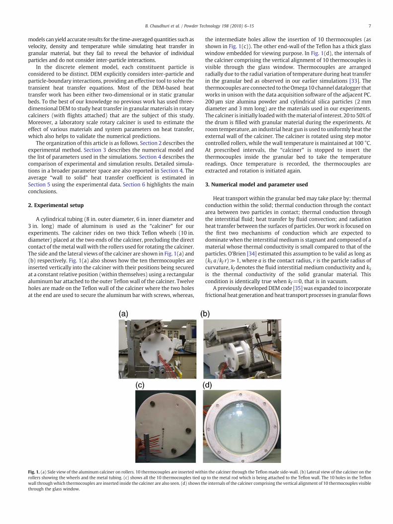
A cylindrical tubing (8 in. outer diameter, 6 in. inner diameter and3 in. long) made of aluminum is used as the “calciner” for ourexperiments. The calciner rides on two thick Teflon wheels (10 in.diameter) placed at the two ends of the calciner, precluding the directcontact of themetal wall with the rollers used for rotating the calciner.The side and the lateral views of the calciner are shown in Fig. 1(a) and(b) respectively. Fig. 1(a) also shows how the ten thermocouples areinserted vertically into the calciner with their positions being securedat a constant relative position (within themselves) using a rectangularaluminum bar attached to the outer Teflonwall of the calciner. Twelveholes are made on the Teflon wall of the calciner where the two holesat the end are used to secure the aluminum bar with screws, whereas,
Fig. 1. (a) Side view of the aluminum calciner on rollers. 10 thermocouples are inserted withrollers showing the wheels and the metal tubing. (c) shows all the 10 thermocouples tied upwall throughwhich thermocouples are inserted inside the calciner are also seen. (d) shows ththrough the glass window.
the intermediate holes allow the insertion of 10 thermocouples (asshown in Fig. 1(c)). The other end-wall of the Teflon has a thick glasswindow embedded for viewing purpose. In Fig. 1(d), the internals ofthe calciner comprising the vertical alignment of 10 thermocouples isvisible through the glass window. Thermocouples are arrangedradially due to the radial variation of temperature during heat transferin the granular bed as observed in our earlier simulations [33]. Thethermocouples are connected to theOmega10 channel datalogger thatworks in unison with the data acquisition software of the adjacent PC.200 μm size alumina powder and cylindrical silica particles (2 mmdiameter and 3 mm long) are the materials used in our experiments.The calciner is initially loadedwith thematerial of interest. 20 to 50% ofthe drum is filled with granular material during the experiments. Atroom temperature, an industrial heat gun is used to uniformly heat theexternal wall of the calciner. The calciner is rotated using step motorcontrolled rollers, while the wall temperature is maintained at 100 °C.At prescribed intervals, the “calciner” is stopped to insert thethermocouples inside the granular bed to take the temperaturereadings. Once temperature is recorded, the thermocouples areextracted and rotation is initiated again.
3. Numerical model and parameter used
Heat transport within the granular bed may take place by: thermalconduction within the solid; thermal conduction through the contactarea between two particles in contact; thermal conduction throughthe interstitial fluid; heat transfer by fluid convection; and radiationheat transfer between the surfaces of particles. Our work is focused onthe first two mechanisms of conduction which are expected todominate when the interstitial medium is stagnant and composed of amaterial whose thermal conductivity is small compared to that of theparticles. O'Brien [34] estimated this assumption to be valid as long as(kS a /kf r)≫1, where a is the contact radius, r is the particle radius ofcurvature, kf denotes the fluid interstitial medium conductivity and kSis the thermal conductivity of the solid granular material. Thiscondition is identically true when kf=0, that is in vacuum.
A previously developedDEM code [35]was expanded to incorporatefrictional heat generation andheat transport processes in granularflows
in the calciner through the Teflonmade side-wall. (b) Lateral view of the calciner on theto the metal rod which is being attached to the Teflon wall. The 10 holes in the Teflone internals of the calciner comprising the vertical alignment of 10 thermocouples visible
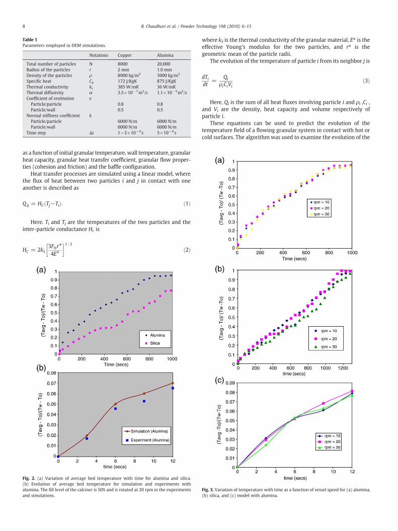
Table 1Parameters employed in DEM simulations.
Notations Copper Alumina
Total number of particles N 8000 20,000Radius of the particles r 2 mm 1.0 mmDensity of the particles ρ 8900 kg/m3 3900 kg/m3
Specific heat Cp 172 J/KgK 875 J/KgKThermal conductivity ks 385 W/mK 36 W/mKThermal diffusivity α 2.5×10⁻⁷m2/s 1.1×10⁻⁵m2/sCoefficient of restitution e
Particle/particle 0.8 0.8Particle/wall 0.5 0.5
Normal stiffness coefficient kParticle/particle 6000 N/m 6000 N/mParticle/wall 6000 N/m 6000 N/m
Time step Δt 1−3×10⁻⁶s 5×10⁻⁶s
8 B. Chaudhuri et al. / Powder Technology 198 (2010) 6–15
as a function of initial granular temperature, wall temperature, granularheat capacity, granular heat transfer coefficient, granular flow proper-ties (cohesion and friction) and the baffle configuration.
Heat transfer processes are simulated using a linear model, wherethe flux of heat between two particles i and j in contact with oneanother is described as
Qij = HCðTj−TiÞ: ð1Þ
Here. Ti and Tj are the temperatures of the two particles and theinter-particle conductance Hc is
HC = 2kS3FNr⁎
4E⁎
� �1=3ð2Þ
Fig. 2. (a) Variation of average bed temperature with time for alumina and silica.(b) Evolution of average bed temperature for simulation and experiments withalumina. The fill level of the calciner is 50% and is rotated at 20 rpm in the experimentsand simulations.
where kS is the thermal conductivity of the granular material, E⁎ is theeffective Young's modulus for the two particles, and r⁎ is thegeometric mean of the particle radii.
The evolution of the temperature of particle i from its neighbor j is
dTidt
=Qi
ρiCiVið3Þ
Here, Qi is the sum of all heat fluxes involving particle i and ρi ,Ci ,and Vi are the density, heat capacity and volume respectively ofparticle i.
These equations can be used to predict the evolution of thetemperature field of a flowing granular system in contact with hot orcold surfaces. The algorithmwas used to examine the evolution of the
Fig. 3. Variation of temperature with time as a function of vessel speed for (a) alumina,(b) silica, and (c) model with alumina.
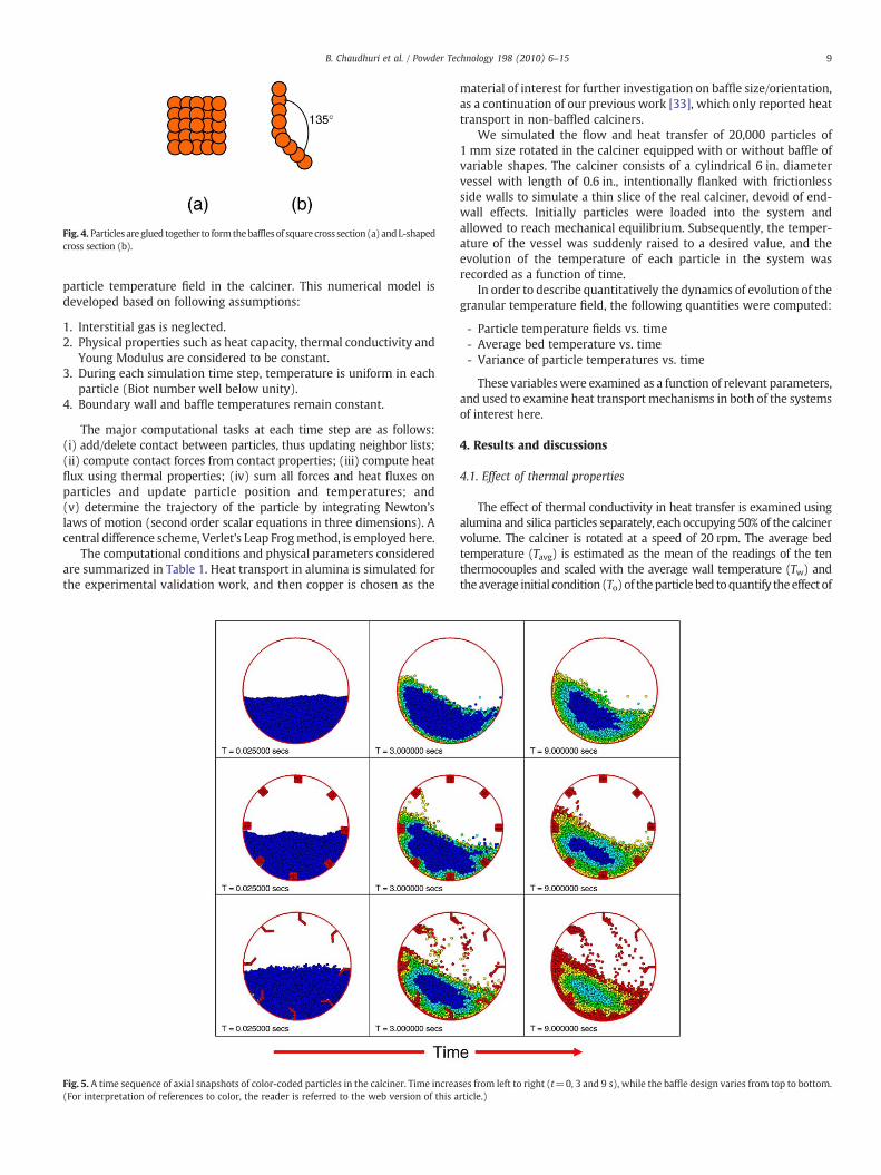
Fig. 4. Particles areglued together to formthebafflesof square cross section (a) andL-shapedcross section (b).
9B. Chaudhuri et al. / Powder Technology 198 (2010) 6–15
particle temperature field in the calciner. This numerical model isdeveloped based on following assumptions:
1. Interstitial gas is neglected.2. Physical properties such as heat capacity, thermal conductivity and
Young Modulus are considered to be constant.3. During each simulation time step, temperature is uniform in each
particle (Biot number well below unity).4. Boundary wall and baffle temperatures remain constant.
The major computational tasks at each time step are as follows:(i) add/delete contact between particles, thus updating neighbor lists;(ii) compute contact forces from contact properties; (iii) compute heatflux using thermal properties; (iv) sum all forces and heat fluxes onparticles and update particle position and temperatures; and(v) determine the trajectory of the particle by integrating Newton'slaws of motion (second order scalar equations in three dimensions). Acentral difference scheme, Verlet's Leap Frogmethod, is employed here.
The computational conditions and physical parameters consideredare summarized in Table 1. Heat transport in alumina is simulated forthe experimental validation work, and then copper is chosen as the
Fig. 5. A time sequence of axial snapshots of color-coded particles in the calciner. Time increa(For interpretation of references to color, the reader is referred to the web version of this a
material of interest for further investigation on baffle size/orientation,as a continuation of our previous work [33], which only reported heattransport in non-baffled calciners.
We simulated the flow and heat transfer of 20,000 particles of1 mm size rotated in the calciner equipped with or without baffle ofvariable shapes. The calciner consists of a cylindrical 6 in. diametervessel with length of 0.6 in., intentionally flanked with frictionlessside walls to simulate a thin slice of the real calciner, devoid of end-wall effects. Initially particles were loaded into the system andallowed to reach mechanical equilibrium. Subsequently, the temper-ature of the vessel was suddenly raised to a desired value, and theevolution of the temperature of each particle in the system wasrecorded as a function of time.
In order to describe quantitatively the dynamics of evolution of thegranular temperature field, the following quantities were computed:
- Particle temperature fields vs. time- Average bed temperature vs. time- Variance of particle temperatures vs. time
These variableswere examined as a function of relevant parameters,and used to examine heat transport mechanisms in both of the systemsof interest here.
4. Results and discussions
4.1. Effect of thermal properties
The effect of thermal conductivity in heat transfer is examined usingalumina and silica particles separately, each occupying 50% of the calcinervolume. The calciner is rotated at a speed of 20 rpm. The average bedtemperature (Tavg) is estimated as the mean of the readings of the tenthermocouples and scaled with the average wall temperature (Tw) andtheaverage initial condition (To)of theparticlebed toquantify theeffect of
ses from left to right (t=0, 3 and 9 s), while the baffle design varies from top to bottom.rticle.)
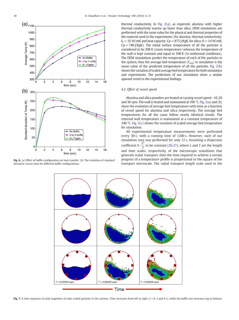
Fig. 6. (a) Effect of baffle configuration on heat transfer. (b) The evolution of standarddeviation versus time for different baffle configurations.
Fig. 7. A time sequence of axial snapshots of color-coded particles in the calciner. Time incr
10 B. Chaudhuri et al. / Powder Technology 198 (2010) 6–15
thermal conductivity. In Fig. 2(a), as expected, alumina with higherthermal conductivity warms up faster than silica. DEM simulations areperformedwith the same value for the physical and thermal properties ofthematerial used in the experiments (for alumina: thermal conductivity:ks=35W/mKandheat capacity: Cp=875 J/KgK, for silica:K=14W/mK,Cp=740 J/KgK). The initial surface temperature of all the particles isconsidered to be 298 K (room temperature) whereas the temperature ofthe wall is kept constant and equal to 398 K (in isothermal conditions).The DEM simulations predict the temperature of each of the particles inthe system, thus the average bed temperature (Tavg) in simulation is themean value of the predicted temperature of all the particles. Fig. 2(b)shows thevariationof scaledaveragebed temperature forboth simulationand experiments. The predictions of our simulation show a similarupward trend to the experimental findings.
4.2. Effect of vessel speed
Alumina and silica powders are heated at varying vessel speed—10, 20and30 rpm. Thewall is heated andmaintained at 100 °C. Fig. 3(a) and (b)show the evolution of average bed temperature with time as a functionof vessel speed for alumina and silica respectively. The average bedtemperatures for all the cases follow nearly identical trends. Theexternal wall temperature is maintained at a constant temperature of100 °C. Fig. 3(c) shows the variation of scaled average bed temperaturefor simulation.
All experimental temperature measurements were performedevery 30 s; with a running time of 1200 s. However, each of oursimulation runs was performed for only 12 s. Assuming a dispersion
coefficient E~L2
Tto be constant [36,37], where L and T are the length
and time scales, respectively, of the microscopic transitions thatgenerate scalar transport, then the time required to achieve a certainprogress of a temperature profile is proportional to the square of thetransport microscale. The radial transport length scale used in the
eases from left to right (t=0, 3 and 9 s), while the baffle size increases top to bottom.
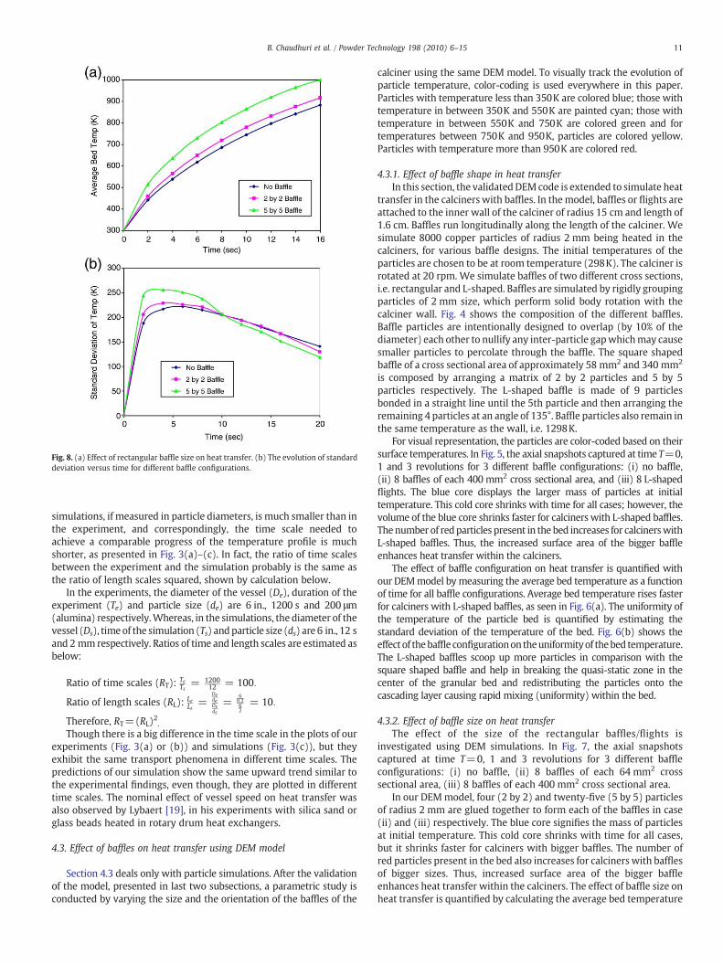
Fig. 8. (a) Effect of rectangular baffle size on heat transfer. (b) The evolution of standarddeviation versus time for different baffle configurations.
11B. Chaudhuri et al. / Powder Technology 198 (2010) 6–15
simulations, if measured in particle diameters, is much smaller than inthe experiment, and correspondingly, the time scale needed toachieve a comparable progress of the temperature profile is muchshorter, as presented in Fig. 3(a)–(c). In fact, the ratio of time scalesbetween the experiment and the simulation probably is the same asthe ratio of length scales squared, shown by calculation below.
In the experiments, the diameter of the vessel (De), duration of theexperiment (Te) and particle size (de) are 6 in., 1200 s and 200 μm(alumina) respectively.Whereas, in the simulations, the diameter of thevessel (Ds), time of the simulation (Ts) andparticle size (ds) are 6 in., 12 sand 2 mm respectively. Ratios of time and length scales are estimated asbelow:
Ratio of time scales (RT): TeTs
= 120012 = 100:
Ratio of length scales (RL): LeLs
=DedeDsds
=60:262
= 10:
Therefore, RT=(RL)2.Though there is a big difference in the time scale in the plots of our
experiments (Fig. 3(a) or (b)) and simulations (Fig. 3(c)), but theyexhibit the same transport phenomena in different time scales. Thepredictions of our simulation show the same upward trend similar tothe experimental findings, even though, they are plotted in differenttime scales. The nominal effect of vessel speed on heat transfer wasalso observed by Lybaert [19], in his experiments with silica sand orglass beads heated in rotary drum heat exchangers.
4.3. Effect of baffles on heat transfer using DEM model
Section 4.3 deals only with particle simulations. After the validationof the model, presented in last two subsections, a parametric study isconducted by varying the size and the orientation of the baffles of the
calciner using the same DEM model. To visually track the evolution ofparticle temperature, color-coding is used everywhere in this paper.Particles with temperature less than 350K are colored blue; those withtemperature in between 350K and 550K are painted cyan; those withtemperature in between 550K and 750K are colored green and fortemperatures between 750K and 950K, particles are colored yellow.Particles with temperature more than 950K are colored red.
4.3.1. Effect of baffle shape in heat transferIn this section, the validatedDEM code is extended to simulate heat
transfer in the calciners with baffles. In themodel, baffles or flights areattached to the inner wall of the calciner of radius 15 cm and length of1.6 cm. Baffles run longitudinally along the length of the calciner. Wesimulate 8000 copper particles of radius 2 mm being heated in thecalciners, for various baffle designs. The initial temperatures of theparticles are chosen to be at room temperature (298K). The calciner isrotated at 20 rpm. We simulate baffles of two different cross sections,i.e. rectangular and L-shaped. Baffles are simulated by rigidly groupingparticles of 2 mm size, which perform solid body rotation with thecalciner wall. Fig. 4 shows the composition of the different baffles.Baffle particles are intentionally designed to overlap (by 10% of thediameter) each other to nullify any inter-particle gapwhichmay causesmaller particles to percolate through the baffle. The square shapedbaffle of a cross sectional area of approximately 58 mm2 and 340 mm2
is composed by arranging a matrix of 2 by 2 particles and 5 by 5particles respectively. The L-shaped baffle is made of 9 particlesbonded in a straight line until the 5th particle and then arranging theremaining 4 particles at an angle of 135°. Baffle particles also remain inthe same temperature as the wall, i.e. 1298K.
For visual representation, the particles are color-coded based on theirsurface temperatures. In Fig. 5, the axial snapshots captured at time T=0,1 and 3 revolutions for 3 different baffle configurations: (i) no baffle,(ii) 8 baffles of each 400 mm2 cross sectional area, and (iii) 8 L-shapedflights. The blue core displays the larger mass of particles at initialtemperature. This cold core shrinks with time for all cases; however, thevolume of the blue core shrinks faster for calciners with L-shaped baffles.Thenumber of redparticles present in the bed increases for calcinerswithL-shaped baffles. Thus, the increased surface area of the bigger baffleenhances heat transfer within the calciners.
The effect of baffle configuration on heat transfer is quantified withour DEMmodel bymeasuring the average bed temperature as a functionof time for all baffle configurations. Average bed temperature rises fasterfor calciners with L-shaped baffles, as seen in Fig. 6(a). The uniformity ofthe temperature of the particle bed is quantified by estimating thestandard deviation of the temperature of the bed. Fig. 6(b) shows theeffect of thebaffle configurationon theuniformityof thebed temperature.The L-shaped baffles scoop up more particles in comparison with thesquare shaped baffle and help in breaking the quasi-static zone in thecenter of the granular bed and redistributing the particles onto thecascading layer causing rapid mixing (uniformity) within the bed.
4.3.2. Effect of baffle size on heat transferThe effect of the size of the rectangular baffles/flights is
investigated using DEM simulations. In Fig. 7, the axial snapshotscaptured at time T=0, 1 and 3 revolutions for 3 different baffleconfigurations: (i) no baffle, (ii) 8 baffles of each 64 mm2 crosssectional area, (iii) 8 baffles of each 400 mm2 cross sectional area.
In our DEMmodel, four (2 by 2) and twenty-five (5 by 5) particlesof radius 2 mm are glued together to form each of the baffles in case(ii) and (iii) respectively. The blue core signifies the mass of particlesat initial temperature. This cold core shrinks with time for all cases,but it shrinks faster for calciners with bigger baffles. The number ofred particles present in the bed also increases for calciners with bafflesof bigger sizes. Thus, increased surface area of the bigger baffleenhances heat transfer within the calciners. The effect of baffle size onheat transfer is quantified by calculating the average bed temperature
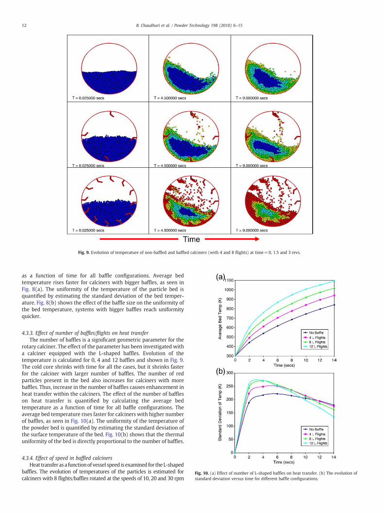
Fig. 10. (a) Effect of number of L-shaped baffles on heat transfer. (b) The evolution ofstandard deviation versus time for different baffle configurations.
Fig. 9. Evolution of temperature of non-baffled and baffled calciners (with 4 and 8 flights) at time=0, 1.5 and 3 revs.
12 B. Chaudhuri et al. / Powder Technology 198 (2010) 6–15
as a function of time for all baffle configurations. Average bedtemperature rises faster for calciners with bigger baffles, as seen inFig. 8(a). The uniformity of the temperature of the particle bed isquantified by estimating the standard deviation of the bed temper-ature. Fig. 8(b) shows the effect of the baffle size on the uniformity ofthe bed temperature, systems with bigger baffles reach uniformityquicker.
4.3.3. Effect of number of baffles/flights on heat transferThe number of baffles is a significant geometric parameter for the
rotary calciner. The effect of the parameter has been investigated witha calciner equipped with the L-shaped baffles. Evolution of thetemperature is calculated for 0, 4 and 12 baffles and shown in Fig. 9.The cold core shrinks with time for all the cases, but it shrinks fasterfor the calciner with larger number of baffles. The number of redparticles present in the bed also increases for calciners with morebaffles. Thus, increase in the number of baffles causes enhancement inheat transfer within the calciners. The effect of the number of baffleson heat transfer is quantified by calculating the average bedtemperature as a function of time for all baffle configurations. Theaverage bed temperature rises faster for calciners with higher numberof baffles, as seen in Fig. 10(a). The uniformity of the temperature ofthe powder bed is quantified by estimating the standard deviation ofthe surface temperature of the bed. Fig. 10(b) shows that the thermaluniformity of the bed is directly proportional to the number of baffles.
4.3.4. Effect of speed in baffled calcinersHeat transfer as a functionof vessel speed is examined for theL-shaped
baffles. The evolution of temperatures of the particles is estimated forcalciners with 8 flights/baffles rotated at the speeds of 10, 20 and 30 rpm
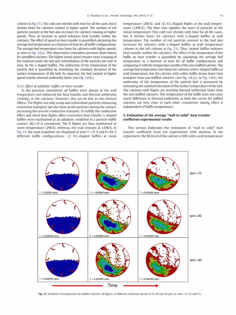
13B. Chaudhuri et al. / Powder Technology 198 (2010) 6–15
(shown in Fig. 11). The cold core shrinks with time for all the cases, but itshrinks faster for calciners rotated at higher speed. The number of redparticles present in the bed also increases for calciners rotating at higherspeeds. Thus, an increase in speed enhances heat transfer within thecalciners. The effect of speed on heat transfer is quantified calculating theaverage bed temperature as a function of time for all baffle configurations.The average bed temperature rises faster for calcinerswith higher speeds,as seen in Fig. 12(a). This observation contradicts previous observationsfor unbaffled calciners. The higher vessel speed ensures more scooping ofthe material inside the bed and redistribution of the particles per unit oftime, by the L-shaped baffles. The uniformity of the temperature of theparticle bed is quantified by estimating the standard deviation of thesurface temperature of the bed. As expected, the bed rotated at higherspeed reaches thermal uniformity faster (see Fig. 12(b)).
4.3.5. Effect of adiabatic baffles on heat transferIn the previous simulations all baffles were always at the wall
temperature and enhanced the heat transfer and thermal uniformity(mixing) in the calciners. However, this can be due to two distincteffects. The flights not only scoop and redistribute particles enhancingconvective transport, but also heat up the particles during the contact,increasing the area for conductive transport. To nullify the conductioneffect and check how flights affect convective heat transfer, L-shapedbaffles were maintained at an adiabatic condition in a particle-bafflecontact, dQ=0 is considered. The 8 flights are thus maintained atroom temperature (298 K) whereas, the wall remains at 1298 K. InFig. 13, the axial snapshots are displayed at time T=0, 4 and 8 s for 2different baffle configurations: (i) 8 L-shaped baffles at room
Fig. 11. Evolution of temperature for baffled calciners (8 flights) at differ
temperature (298 K) and (ii) 8 L-shaped flights at the wall temper-ature (1298 K). The blue core signifies the mass of particles at theinitial temperature. This cold core shrinks with time for all the cases,but it shrinks faster for calciners with L-shaped baffles at walltemperature. The number of red particles present in the bed alsoincreases for calciners with L-shaped baffles at wall temperature(shown in the left column in Fig. 13). Thus, heated baffles enhanceheat transfer within the calciners. The effect of the temperature of thebaffle on heat transfer is quantified by calculating the average bedtemperature as a function of time for all baffle configurations andcomparing itwith the temperature profile of the non-baffled calciner. Theaveragebed temperature rises faster for calcinerswith L-shapedbaffles atwall temperature, but the calciner with colder baffle shows faster heattransport than non-baffled calciners (see Fig. 14(a)). In Fig. 14(b), theuniformity of the temperature of the particle bed is presented byestimating the standard deviation of the surface temperature of the bed.The calciners with flights are reaching thermal uniformity faster thanthe non-baffled calciners. The temperature of the baffle does not causemuch difference in thermal uniformity as both the curves for baffledcalciners are very close to each other (convective mixing effect isindependent of baffle temperature).
5. Estimation of the average “wall to solid” heat transfercoefficient-experimental results
This section elaborates the estimation of “wall to solid” heattransfer coefficient from our experiments with alumina. In theexperiment, the fill level of the calciner is 50%with a wall temperature
ent rotational speeds of 10, 20 and 30 rpm, at time=0, 4.5 and 9 s.
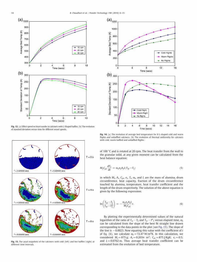
Fig. 13. The axial snapshots of the calciners with cold (left) and hot baffles (right) atdifferent time intervals.
Fig. 12. (a) Effect speed onheat transfer in calcinerswith L-Shaped baffles. (b) The evolutionof standard deviation versus time for different vessel speeds.
Fig. 14. (a) The evolution of average bed temperature for 8 L-shaped cold and warmflights and unbaffled calciners. (b) The evolution of thermal uniformity for calcinerswith cold, warm baffled and unbaffled flights.
14 B. Chaudhuri et al. / Powder Technology 198 (2010) 6–15
of 100 °C and is rotated at 20 rpm. The heat transfer from the wall tothe granular solid, at any given moment can be calculated from theheat balance equation:
MSCpSdTSdt
= αSeSASLðTW−TSÞ ð5Þ
in which Ms, As, Cps, es, Ts, αs, and L are the mass of alumina, drumcircumference, heat capacity, fraction of the drum circumferencetouched by alumina, temperature, heat transfer coefficient and thelength of the drum respectively. The solution of the above equation isgiven by the following expression:
lnTW−TSTW−TO
S
!= −αSeSASL
MSCpSt: ð6Þ
By plotting the experimentally determined values of the naturallogarithm of the ratio of Tw−TS and Tw−ToS versus elapsed time, αS
can be calculated from the slope of the best fit straight line drawncorresponding to the data points in the plot (see Fig. 15). The slope ofthe line is −0.0023. Now equating this value with the coefficient of tof Eq. (6), we calculate αS=72.47 W/m2K. In this calculation, weconsidered Ms=875 g; As=0.203π m2; Cps=875 J/KgK; es=0.5;and L=0.0762 m. Thus average heat transfer coefficient can beestimated from the evolution of bed temperature.
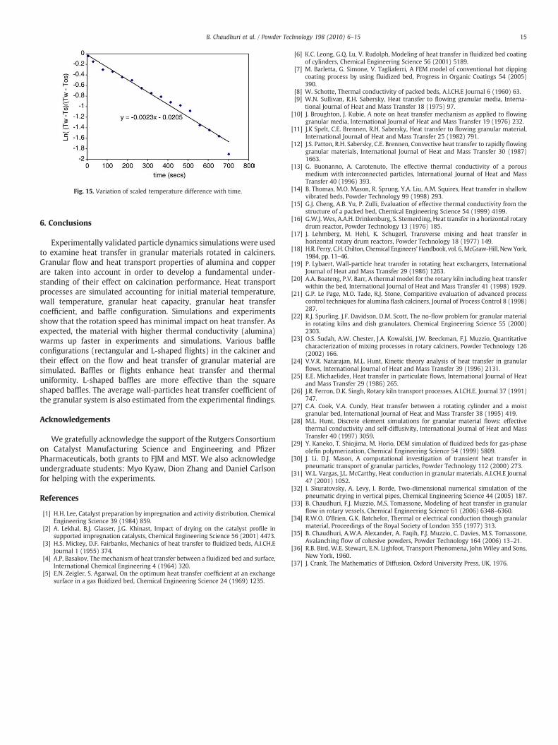
Fig. 15. Variation of scaled temperature difference with time.
15B. Chaudhuri et al. / Powder Technology 198 (2010) 6–15
6. Conclusions
Experimentally validated particle dynamics simulations were usedto examine heat transfer in granular materials rotated in calciners.Granular flow and heat transport properties of alumina and copperare taken into account in order to develop a fundamental under-standing of their effect on calcination performance. Heat transportprocesses are simulated accounting for initial material temperature,wall temperature, granular heat capacity, granular heat transfercoefficient, and baffle configuration. Simulations and experimentsshow that the rotation speed has minimal impact on heat transfer. Asexpected, the material with higher thermal conductivity (alumina)warms up faster in experiments and simulations. Various baffleconfigurations (rectangular and L-shaped flights) in the calciner andtheir effect on the flow and heat transfer of granular material aresimulated. Baffles or flights enhance heat transfer and thermaluniformity. L-shaped baffles are more effective than the squareshaped baffles. The average wall-particles heat transfer coefficient ofthe granular system is also estimated from the experimental findings.
Acknowledgements
We gratefully acknowledge the support of the Rutgers Consortiumon Catalyst Manufacturing Science and Engineering and PfizerPharmaceuticals, both grants to FJM and MST. We also acknowledgeundergraduate students: Myo Kyaw, Dion Zhang and Daniel Carlsonfor helping with the experiments.
References
[1] H.H. Lee, Catalyst preparation by impregnation and activity distribution, ChemicalEngineering Science 39 (1984) 859.
[2] A. Lekhal, B.J. Glasser, J.G. Khinast, Impact of drying on the catalyst profile insupported impregnation catalysts, Chemical Engineering Science 56 (2001) 4473.
[3] H.S. Mickey, D.F. Fairbanks, Mechanics of heat transfer to fluidized beds, A.I.CH.EJournal 1 (1955) 374.
[4] A.P. Basakov, The mechanism of heat transfer between a fluidized bed and surface,International Chemical Engineering 4 (1964) 320.
[5] E.N. Zeigler, S. Agarwal, On the optimum heat transfer coefficient at an exchangesurface in a gas fluidized bed, Chemical Engineering Science 24 (1969) 1235.
[6] K.C. Leong, G.Q. Lu, V. Rudolph, Modeling of heat transfer in fluidized bed coatingof cylinders, Chemical Engineering Science 56 (2001) 5189.
[7] M. Barletta, G. Simone, V. Tagliaferri, A FEM model of conventional hot dippingcoating process by using fluidized bed, Progress in Organic Coatings 54 (2005)390.
[8] W. Schotte, Thermal conductivity of packed beds, A.I.CH.E Journal 6 (1960) 63.[9] W.N. Sullivan, R.H. Sabersky, Heat transfer to flowing granular media, Interna-
tional Journal of Heat and Mass Transfer 18 (1975) 97.[10] J. Broughton, J. Kubie, A note on heat transfer mechanism as applied to flowing
granular media, International Journal of Heat and Mass Transfer 19 (1976) 232.[11] J.K Spelt, C.E. Brennen, R.H. Sabersky, Heat transfer to flowing granular material,
International Journal of Heat and Mass Transfer 25 (1982) 791.[12] J.S. Patton, R.H. Sabersky, C.E. Brennen, Convective heat transfer to rapidly flowing
granular materials, International Journal of Heat and Mass Transfer 30 (1987)1663.
[13] G. Buonanno, A. Carotenuto, The effective thermal conductivity of a porousmedium with interconnected particles, International Journal of Heat and MassTransfer 40 (1996) 393.
[14] B. Thomas, M.O. Mason, R. Sprung, Y.A. Liu, A.M. Squires, Heat transfer in shallowvibrated beds, Powder Technology 99 (1998) 293.
[15] G.J. Cheng, A.B. Yu, P. Zulli, Evaluation of effective thermal conductivity from thestructure of a packed bed, Chemical Engineering Science 54 (1999) 4199.
[16] G.W.J. Wes, A.A.H. Drinkenburg, S. Stemerding, Heat transfer in a horizontal rotarydrum reactor, Powder Technology 13 (1976) 185.
[17] J. Lehmberg, M. Hehl, K. Schugerl, Transverse mixing and heat transfer inhorizontal rotary drum reactors, Powder Technology 18 (1977) 149.
[18] H.R. Perry, C.H. Chilton, Chemical Engineers' Handbook, vol. 6,McGraw-Hill, New York,1984, pp. 11–46.
[19] P. Lybaert, Wall-particle heat transfer in rotating heat exchangers, InternationalJournal of Heat and Mass Transfer 29 (1986) 1263.
[20] A.A. Boateng, P.V. Barr, A thermal model for the rotary kiln including heat transferwithin the bed, International Journal of Heat and Mass Transfer 41 (1998) 1929.
[21] G.P. Le Page, M.O. Tade, R.J. Stone, Comparitive evaluation of advanced processcontrol techniques for alumina flash calciners, Journal of Process Control 8 (1998)287.
[22] R.J. Spurling, J.F. Davidson, D.M. Scott, The no-flow problem for granular materialin rotating kilns and dish granulators, Chemical Engineering Science 55 (2000)2303.
[23] O.S. Sudah, A.W. Chester, J.A. Kowalski, J.W. Beeckman, F.J. Muzzio, Quantitativecharacterization of mixing processes in rotary calciners, Powder Technology 126(2002) 166.
[24] V.V.R. Natarajan, M.L. Hunt, Kinetic theory analysis of heat transfer in granularflows, International Journal of Heat and Mass Transfer 39 (1996) 2131.
[25] E.E. Michaelides, Heat transfer in particulate flows, International Journal of Heatand Mass Transfer 29 (1986) 265.
[26] J.R. Ferron, D.K. Singh, Rotary kiln transport processes, A.I.CH.E. Journal 37 (1991)747.
[27] C.A. Cook, V.A. Cundy, Heat transfer between a rotating cylinder and a moistgranular bed, International Journal of Heat and Mass Transfer 38 (1995) 419.
[28] M.L. Hunt, Discrete element simulations for granular material flows: effectivethermal conductivity and self-diffusivity, International Journal of Heat and MassTransfer 40 (1997) 3059.
[29] Y. Kaneko, T. Shiojima, M. Horio, DEM simulation of fluidized beds for gas-phaseolefin polymerization, Chemical Engineering Science 54 (1999) 5809.
[30] J. Li, D.J. Mason, A computational investigation of transient heat transfer inpneumatic transport of granular particles, Powder Technology 112 (2000) 273.
[31] W.L. Vargas, J.L. McCarthy, Heat conduction in granular materials, A.I.CH.E Journal47 (2001) 1052.
[32] I. Skuratovsky, A. Levy, I. Borde, Two-dimensional numerical simulation of thepneumatic drying in vertical pipes, Chemical Engineering Science 44 (2005) 187.
[33] B. Chaudhuri, F.J. Muzzio, M.S. Tomassone, Modeling of heat transfer in granularflow in rotary vessels, Chemical Engineering Science 61 (2006) 6348–6360.
[34] R.W.O. O'Brien, G.K. Batchelor, Thermal or electrical conduction though granularmaterial, Proceedings of the Royal Society of London 355 (1977) 313.
[35] B. Chaudhuri, A.W.A. Alexander, A. Faqih, F.J. Muzzio, C. Davies, M.S. Tomassone,Avalanching flow of cohesive powders, Powder Technology 164 (2006) 13–21.
[36] R.B. Bird, W.E. Stewart, E.N. Lighfoot, Transport Phenomena, John Wiley and Sons,New York, 1960.
[37] J. Crank, The Mathematics of Diffusion, Oxford University Press, UK, 1976.