Can DC Motors Directly Drive Flapping Wings at High Frequency and Large Wing Strokes?
12
PRE-PRINT OF A MANUSCRIPT ACCEPTED FOR PUBLICATION ON IEEE/ASME TRANSACTIONS ON MECHATRONICS 1 Can DC motors directly drive flapping wings at high frequency and large wing strokes? Domenico Campolo * , Muhammad Azhar, Gih-Keong Lau and Metin Sitti Abstract—This work proposes and experimentally validates a method for driving flapping wings at large wing strokes and high frequencies with a DC motor, based on direct, elastic transmission. The DC motor undergoes reciprocating, rather than rotary, motion avoiding the use of nonlinear transmissions such as slider-crank mechanisms. This is key to compact, easy to fabricate, power efficient, and controllable flapping mecha- nisms. First, an appropriate motor based on maximum power transfer arguments is selected. Then a flapping mechanism is prototyped and its experimental performance is compared with simulations, which take into account the full dynamics of the system. Despite inherent nonlinearities due to the aerodynamic damping, the linearity of the direct, elastic transmission allows one to fully exploit resonance. This benefit is best captured by the dynamic efficiency, close to 90% at larger wing strokes in both experimental data and simulations. We finally show a compact flapping mechanism implementation with independent flapping motion control for the two wings, which could be used for future autonomous micro-aerial vehicles. Index Terms—DC motor selection, direct elastic transmission, bio-inspired, resonant wings. I. I NTRODUCTION Recent years have witnessed an increase of research ef- forts in what is generally referred to as biomimetic robotics. Attracted by the unmatched performance of living systems, roboticists have started applying design principles drawing inspiration from biological evidence. In particular, agility and maneuverability in air of living flyers has inspired the development of an increasing number of so-called Micro Aerial Vehicles (MAVs) [1], [2]. Besides bio-inspired sensing capabilities and neuro-inspired forms of controllers [3], there has been a technological push towards the development of biomimetic forms of propulsion, with particular emphasis on flapping wings. Flapping locomotion is superior to other forms of propulsions especially at lower speeds. Unparalleled by man-made vehicles, animals such birds, bats, insects are in fact capable of fast forward motion as well as hovering, which is one of the most energetically challenging forms of locomotion since it cannot exploit the accumulated kinetic energy of the body as in forward swimming/flying [4]. Efficient power usage is fundamental for the development of flapping propellers. One of the limits to flapping propulsion, also faced by living systems especially at larger size, is D. Campolo, M. Azhar and G.K. Lau are with the School of Mechanical and Aerospace Engineering, Nanyang Technological University, Singapore 639798. M. Sitti is with the Department of Mechanical Engineering, Carnegie Mellon University, Pittsburgh, PA 15213. * Corresponding author: [email protected] represented by the inertia of the wings. The need to periodi- cally accelerate/decelerate the inertia of the appendices poses serious constraints to the flapping modality. Although the primary interest is doing work against the air, as this directly translates into production of lift and thrust forces, it is not uncommon that accelerating/decelerating wings at relatively high frequencies might require much larger inertial torques than damping ones. This would lead to oversized muscles (and actuators for artificial systems). A first biological observation concerns the fundamental role played by resonance, physiologically induced by the structural elasticity typically inherent to the biomechanical properties of muscles and, for insects, of the external cuticle. The presence of elastic components for storage and release of the kinetic energy of the wings avoids the unnecessary waste of inertial power [4]. Indeed, such a principle has been successfully adopted in the design of flapping wings for robotic applications [5], [6], [7]. As emphasized by Baek, Ma and Fearing [7], at the smallest scales the principle of mechanical resonance is widely imple- mented, in artificial systems, because elasticity is inherently present in both structures and actuators. On the other hand, at larger scales, where DC motors become a convenient choice for designers, the resonance principle is ‘almost forgotten’. The reason is that most approaches, e.g. see the ‘DelfFly’ [8], typically deploy slider-crank mechanisms to generate recipro- cating motion from the DC motor rotary motion. Few attempts have been made to recover energy via an elastic element [9], [7] but the nonlinearity of the transmission reduces the benefits of resonance. From a controllability perspective, a drawback of conventional slider-crank based wing flappers is that, once the mechanism is designed, the possible wing angles are in fact fixed and the only control parameter is the motor speed, allowing one to vary the flapping frequency but neither the wing-stroke nor the mean flapping angle. In previous work [10], we showed how independent control of these parameters is beneficial for controllability of an autonomous, 2-winged flyer. In fact, flapping frequency directly affects the average lift while rolling torques can be generated by asymmetric wing- strokes and pitching torques can be generated by shifting the wing strokes along the flapping plane by changing the average flapping angle. The objective of this work is investigating a novel use of ro- tary DC motors for direct driving flapping wings at resonance, without using nonlinear transmissions such as slider-crank mechanisms. The use of an elastic mechanism, tuned to res- onate with the wings/motor inertia, will relieve the motor from generating the high torques required to accelerate/decelerate
-
Upload
independent -
Category
Documents
-
view
1 -
download
0
Transcript of Can DC Motors Directly Drive Flapping Wings at High Frequency and Large Wing Strokes?

PRE-PRINT OF A MANUSCRIPT ACCEPTED FOR PUBLICATION ON IEEE/ASME TRANSACTIONS ON MECHATRONICS 1
Can DC motors directly drive flapping wingsat high frequency and large wing strokes?
Domenico Campolo∗, Muhammad Azhar, Gih-Keong Lau and Metin Sitti
Abstract—This work proposes and experimentally validates amethod for driving flapping wings at large wing strokes andhigh frequencies with a DC motor, based on direct, elastictransmission. The DC motor undergoes reciprocating, ratherthan rotary, motion avoiding the use of nonlinear transmissionssuch as slider-crank mechanisms. This is key to compact, easyto fabricate, power efficient, and controllable flapping mecha-nisms. First, an appropriate motor based on maximum powertransfer arguments is selected. Then a flapping mechanism isprototyped and its experimental performance is compared withsimulations, which take into account the full dynamics of thesystem. Despite inherent nonlinearities due to the aerodynamicdamping, the linearity of the direct, elastic transmission allowsone to fully exploit resonance. This benefit is best captured by thedynamic efficiency, close to 90% at larger wing strokes in bothexperimental data and simulations. We finally show a compactflapping mechanism implementation with independent flappingmotion control for the two wings, which could be used for futureautonomous micro-aerial vehicles.
Index Terms—DC motor selection, direct elastic transmission,bio-inspired, resonant wings.
I. INTRODUCTION
Recent years have witnessed an increase of research ef-forts in what is generally referred to as biomimetic robotics.Attracted by the unmatched performance of living systems,roboticists have started applying design principles drawinginspiration from biological evidence. In particular, agilityand maneuverability in air of living flyers has inspired thedevelopment of an increasing number of so-called MicroAerial Vehicles (MAVs) [1], [2]. Besides bio-inspired sensingcapabilities and neuro-inspired forms of controllers [3], therehas been a technological push towards the development ofbiomimetic forms of propulsion, with particular emphasis onflapping wings. Flapping locomotion is superior to other formsof propulsions especially at lower speeds. Unparalleled byman-made vehicles, animals such birds, bats, insects are in factcapable of fast forward motion as well as hovering, which isone of the most energetically challenging forms of locomotionsince it cannot exploit the accumulated kinetic energy of thebody as in forward swimming/flying [4].
Efficient power usage is fundamental for the development offlapping propellers. One of the limits to flapping propulsion,also faced by living systems especially at larger size, is
D. Campolo, M. Azhar and G.K. Lau are with the School of Mechanicaland Aerospace Engineering, Nanyang Technological University, Singapore639798.
M. Sitti is with the Department of Mechanical Engineering, CarnegieMellon University, Pittsburgh, PA 15213.
∗Corresponding author: [email protected]
represented by the inertia of the wings. The need to periodi-cally accelerate/decelerate the inertia of the appendices posesserious constraints to the flapping modality. Although theprimary interest is doing work against the air, as this directlytranslates into production of lift and thrust forces, it is notuncommon that accelerating/decelerating wings at relativelyhigh frequencies might require much larger inertial torquesthan damping ones. This would lead to oversized muscles (andactuators for artificial systems).
A first biological observation concerns the fundamental roleplayed by resonance, physiologically induced by the structuralelasticity typically inherent to the biomechanical properties ofmuscles and, for insects, of the external cuticle. The presenceof elastic components for storage and release of the kineticenergy of the wings avoids the unnecessary waste of inertialpower [4]. Indeed, such a principle has been successfullyadopted in the design of flapping wings for robotic applications[5], [6], [7].
As emphasized by Baek, Ma and Fearing [7], at the smallestscales the principle of mechanical resonance is widely imple-mented, in artificial systems, because elasticity is inherentlypresent in both structures and actuators. On the other hand, atlarger scales, where DC motors become a convenient choicefor designers, the resonance principle is ‘almost forgotten’.The reason is that most approaches, e.g. see the ‘DelfFly’ [8],typically deploy slider-crank mechanisms to generate recipro-cating motion from the DC motor rotary motion. Few attemptshave been made to recover energy via an elastic element [9],[7] but the nonlinearity of the transmission reduces the benefitsof resonance. From a controllability perspective, a drawbackof conventional slider-crank based wing flappers is that, oncethe mechanism is designed, the possible wing angles are infact fixed and the only control parameter is the motor speed,allowing one to vary the flapping frequency but neither thewing-stroke nor the mean flapping angle. In previous work[10], we showed how independent control of these parametersis beneficial for controllability of an autonomous, 2-wingedflyer. In fact, flapping frequency directly affects the average liftwhile rolling torques can be generated by asymmetric wing-strokes and pitching torques can be generated by shifting thewing strokes along the flapping plane by changing the averageflapping angle.
The objective of this work is investigating a novel use of ro-tary DC motors for direct driving flapping wings at resonance,without using nonlinear transmissions such as slider-crankmechanisms. The use of an elastic mechanism, tuned to res-onate with the wings/motor inertia, will relieve the motor fromgenerating the high torques required to accelerate/decelerate

PRE-PRINT OF A MANUSCRIPT ACCEPTED FOR PUBLICATION ON IEEE/ASME TRANSACTIONS ON MECHATRONICS 2
the wings/motor inertia. We specifically focus on hovering,one of the most power-demanding forms of locomotion andfor which the benefits of resonance can be mostly appreciated.Although the proposed principle is general and applicable at allscales, this project shall mainly target 10 grams flyers, whichare comparable in size and weight with small hummingbirdsfor which a large body of biological observation exists. Assuch, our main specification will be flapping frequencies in therange of 20-40 Hz and wing-strokes as large as ±60 degrees.
In the following, we shall first introduce a simplifiedaerodynamic model, which allows taking into account thenonlinearities of aerodynamic damping without delving intocomplex fluid dynamics approaches. Based on a secondbiological observation that wing motion in real flyers is‘quasi-sinusoidal’, a simplified analysis is applied to representaerodynamic damping as a (nonlinear) equivalent electricalimpedance. Maximum power transfer arguments are used toselect a motor, based on impedance matching.
We then describe the development of a prototype, emphasiz-ing the implementation details which avoid the introduction ofunnecessary nonlinearities in the system dynamics, besides theinherent nonlinear aerodynamic damping. We characterize theprototype and compare the experimental data with simulationswhich take into account the full dynamics of the system. Wefinally show a compact implementation which is a suitablecandidate for a future, autonomous micro-aerial vehicle.
Along with this paper, a video is provided which showsfabrication details as well the operation of the two prototypesin both real time and slow motion.
II. MODELS AND SIMPLIFIED ANALYSIS ATQUASI-SINUSOIDAL REGIME
A. Wing Aerodynamics: Nonlinear Damping
When a wing moves in a surrounding fluid, energy istransferred to the fluid and reaction forces arise. In principle,the force distribution on the wing may be derived from theNavier-Stokes equations. In practice, accuracy of the solutionsto this problem is guaranteed only by numerical approaches.However, when accuracy requirements are not so stringent,reliable simplifications can be used which are based on theassumption of steady or quasi-steady flow, [11]. Such modelsare based on quasi-steady blade element analysis, whereby thewing is assumed to be divided into a finite number of stripsand each is analyzed independently.
For a wing of length R, blade element analysis considersinfinitesimal strips at distance r from the fulcrum and ofinfinitesimal area c(r) dr, where c(r) is the wing chord whichdetermines the geometric profile.
For each section, the instantaneous drag torque is
dB =1
2ρCD r (r · ω)2 sign(ω) c(r) dr
where ρ is the density of the fluid (for air ρ = 1.2Kg/m3),CD is the adimensional drag coefficient, and r ·ω is the linearvelocity of the section. CD depends on the angle of attack (i.e.inclination of the wing/fin with respect to the fluid velocity),therefore is in principle time dependent and can be averagedout throughout the motion [12].
For a given wing, the above equations can be integratedover the whole wing length, leading to:
B(ω) =
∫ R
0
dB = B0ω2 sign(ω) (1)
where the torque damping coefficient B0 is defined as:
B0 =1
2ρCD
∫ R
0
r3c(r) dr (2)
In this paper we target small hummingbird wings, such asthe one in Fig. 1, flapping at approximately 35Hz. Fabricationdetails for the wings will be given later on. Here we just men-tion that, based on the geometry and material properties of thefabricated wings shown in Fig. 1, the damping coefficient B0
in (2) and the inertia Jw for a single wing (in our experimentswe will use two wings) were numerically evaluated to be
B0 = 1.32 · 10−9 Kgm2 rad−2 (3)Jw = 9.53 · 10−9Kgm2 (4)
40o
Leading edge vein
Crossing vein
Membrane
Fig. 1. Artificial wing used in our experiments. Based on Zhao et al. [13],a crossing vein at 40 deg with the leading edge was introduced to ensurerigidity of the wing.
B. Analysis at Quasi-Sinusoidal Regime
Following [14] and based on biological observations [12],[15], quasi-sinusoidal regime assumptions allow estimatingpower requirements at steady state for a given stroke angle±θ0 and a given flapping frequency f0. Wing kinematics (i.e.angular position, velocity and acceleration) can be expressedas
θ = θ0 sin(2πf0t) (5)ω = Ω0 cos(2πf0t) (6)α = −2πf0Ω0 sin(2πf0t) (7)
where Ω0 denotes the angular speed amplitude:
Ω0 := 2πf0θ0 (8)
By introducing the concept of equivalent proportional damp-ing1, the power dissipated against drag can be estimated as
1For a given amplitude of a sinusoidal trajectory, an equivalent lineardamper dissipates the same power as the nonlinear damper in (1), see [14]

PRE-PRINT OF A MANUSCRIPT ACCEPTED FOR PUBLICATION ON IEEE/ASME TRANSACTIONS ON MECHATRONICS 3
Pdrag = B(ω)ω = B08
3πΩ0ω
2 (9)
with a peak power (equivalent to the power amplitude)
Pdrag =∣∣∣Pdrag
∣∣∣ = B08
3πΩ3
0 (10)
III. DC MOTOR SELECTION VIA IMPEDANCE MATCHING
Unlike gliding, hovering is very challenging from an actu-ator perspective. For wing-strokes of ±60 deg, the inertial toaerodynamic torque ratio, for quasi-sinusoidal motions, can bequickly estimated to be
τinertialτaero
=Jw(2πf0)
2θ0B0(2πf0θ0)2
=JwB0θ0
≈ 6.9 (11)
Therefore, torques required to accelerate/decelerate the winginertia are much larger than aerodynamic torques. For anactuator to drive a wing, the minimum requirement is toproduce at least the same amount of power which is dissipatedby the aerodynamic damping. If the actuator is also required tohandle the peak inertial torques (e.g. five times higher than theaerodynamic ones) then the motor selection would necessarilylead to an oversized actuator, i.e. with a rated power which ismuch larger than the minimum aerodynamic requirements.
A. Simplified Analysis at Quasi-Sinusoidal Regime
In the case of quasi-sinusoidal kinematics, as for hum-mingbirds, exploiting resonance using a spring to resonatewith the wing inertia at the desired frequency (f0) can beextremely advantageous, also in presence of nonlinearitiessuch as aerodynamic damping. To this end, let’s consider awing with inertia Jw, subject to aerodynamic damping B(ω),attached to a torsion spring with rotational stiffness K, anddirectly driven by a DC motor exerting a torque τm. This iscaptured by the following second order system:
Jw α+B(ω) +Kθ = τm (12)
The electro-mechanical model of a DC motor driving themechanical system (12) can be written2 as
V = R0I + kaωkaI = Jtotα+ (b0 +B0ω sign(ω))ω +Kθ
(13)
where V and I are, respectively, the voltage and current at themotor terminals; ω and α are, respectively, the angular speedand the angular acceleration of the rotor; R0 is the electricalresistance of the armature; ka is the armature constant; b0 is thedamping constant due to the internal friction (motor bearings);Jtot := Jm + 2 × Jw accounts for both rotor Jm and wingsinertia 2× Jw.
Resonance can be set to occur at frequency f0 by selectingthe appropriate value K for rotational stiffness
K = (2πf0)2Jtot (14)
2The armature inductance is neglected as the electrical dynamics are muchfaster than the mechanical ones, see [14].
then at sinusoidal regime, using (5-7), the inertial torque andthe elastic torque will balance one another Jtotα+Kθ = 0.
At resonance, sinusoidal voltage and current inputs of am-plitude, respectively, V0 and I0 can be expressed as functionsof Ω0 as follows:
V0 = R0k−1a
(b0 +
83πB0Ω0
)Ω0 + kaΩ0
I0 = k−1a
(b0 +
83πB0Ω0
)Ω0
(15)
Of course, for a given kinematics Ω0, theoretical values forvoltage and current amplitude can always be found from (15)but these might exceed the rated limits. Based on a recentmethod presented in [14], a power analysis will be developedwhich allows us to graphically select appropriate motors.
B. Power Estimates
The instantaneous power balance can be obtained from (15)and can be rewritten to highlight the power dissipated againstmechanical damping (input electrical power minus electricallosses, see [14]):
Pmechdef= V I −R0I
2 =1
ηxPdrag (16)
where Pdrag is as in (9) and the efficiency ηx is defined as
ηx =
(1 +
b083πB0Ω0
)−1
to take into account the mechanical power dissipated againstfriction instead of aerodynamic drag.
The maximum power transfer theorem for linear networksstates that, for a given nominal input voltage, the maximummechanical power delivered to the load equals the electricallosses, leading to a maximum 50% efficiency which can onlybe achieved in the case of impedance matching condition.
A similar result can be derived here, following [14]. Theinstantaneous mechanical power balance (16) can be writtenas
ηx1
2
V 20
2R0=
1
µPdrag (17)
where Pdrag is given in (10), Rmech is the equivalent mechan-ical resistance, µ is the impedance mismatch factor and aredefined, respectively, as
Rmech :=ηxK
2a
83πB0Ω0
(18)
µ := 4Rmech/R0
(1 +Rmech/R0)2 (19)
Note that 0 < µ ≤ 1 for all R0, Rmech > 0 and alsothat µ = 1 if and only if R0 = Rmech, meaning that thepower dissipated across Rmech equals the power dissipatedacross R0, i.e. a 50% efficiency. In the best case scenario (i.e.impedance matching condition: Rmech = R0) the total inputpower is V 2/(2R0) and only half of it can be transferred tothe mechanical load.
The advantage is that (17) provides an interpretation interms of power and leads to a graphical representation usefulfor motor selection, as we shall see next.

PRE-PRINT OF A MANUSCRIPT ACCEPTED FOR PUBLICATION ON IEEE/ASME TRANSACTIONS ON MECHATRONICS 4
model weight V0 n0 Tstall Pmax I0 Istall Kt R0 b0grams V rad/sec mNm mW mA mA mNm/A Ω nNm·sec/rad
1 104-001 0.5 3 5236 0.03 39 16 70 0.4 42.9 13.12 104-003 0.8 1.3 3037 0.04 30 14 90 0.4 14.4 20.53 106-001 1.4 1.3 2513 0.14 88 30 340 0.4 3.7 47.74 107-001 2.4 1.5 994.8 0.25 62 20 170 1.5 8.8 29.65 108-004 3.7 3 1885 0.93 438 50 600 1.6 5 41.16 108-005 2.5 3 1885 0.72 339 46 450 1.6 (1.3∗) 6.7 (8.8∗) 39.07 110-001 3 3 1623.1 0.5 203 40 300 1.7 10 41.18 110-002 3.7 1.5 1361.4 0.58 197 70 750 0.8 2 39.89 110-003 4.9 1.3 994.8 0.37 92 40 390 0.9 3.3 38.110 112-001 8 2.4 1675.5 1.55 649 150 1250 1.2 1.9 111
(*) actual values as measured from a specific ‘108-005’ model
TABLE IMOTOR PARAMETERS FROM PRECISION MICRODRIVES LTD. [16]
C. Impedance Matching and Motor Selection
Each term in (17) is a function of the desired kinematics Ω0,defined in (8) based on a desired stroke angle θ0 and a desiredflapping frequency f0. The power Pdrag to be dissipatedagainst aerodynamic damping is the minimum amount that themotor should be able to deliver. In fact, the required powerto be delivered could be even larger in case of impedancemismatch µ < 1, as indicated by the right-hand side of (17).The left-hand side of (17) represents the available power,corresponding to the maximum power that can be transferredto an optimally matched load, i.e. one half of V 2
0 /(2R0),further reduced by inefficiencies due to friction (ηx).
The right-hand side of (17) does not depend on motorparameters and only reflects requirements of the load (theflapping wing). The left-hand side of (17) is motor-specificand, for each Ω0, it is possible to determine whether theoperating conditions exceed any given limit, see [14] fordetails.
Considering a pair of wings, each similar to the one inFig. 1, a mechanical inertia Jw = 2× 9.53 · 10−9 Kgm2 andaerodynamic damping B0 = 2 × 1.32 · 10−9 Kgm2 rad−2
can be estimated, as in (3) and (4). For a desired stroke-angleθ0 = ±60 deg and flapping frequency f0 = 35 Hz, the speedamplitude can be determined to be Ω0 = 2πf0θ0 = 230.3rad/sec.
As possible actuators, we focused on commercially avail-able, low-cost DC motors. Although this type of motor iswidely available, e.g. for the toy industry, very few man-ufacturers provide detailed electromechanical characteristics.Among the few possible choices, we selected DC motorsmanufactured by Precision Microdrives Ltd. [16] and therelevant characteristics for each model are reported in Table I.
Fig. 2 graphically represents equation (17) on a power vs.impedance ratio plot. The right-hand side of (17), i.e. therequired power, is represented by the U-shaped curves for threedifferent stroke-angles at 35 Hz. In particular, we are interestedin the thickest curve, i.e. ±60 deg stroke-angle. The left-handside of (17), i.e. the available power, is represented by a line foreach motor (identified by the number on top of the line whichcorresponds to the first column in Table I). The intersectionof a motor line with a specific U-shaped curve identifies thepower required to resonate the wing at a specific stroke-angleand frequency. A motor line graphically terminates whenever
10−2
10−1
100
101
102
10−2
10−1
1
2
3
4
5678
9
10
*
Rmech
/ R0
pow
er [W
]
µ−1 Pdrag
at ± 60o
µ−1 Pdrag
at ± 50o
µ−1 Pdrag
at ± 40o
Fig. 2. Power vs. impedance ratio plot. U-shaped curves represent requiredpower for different stroke-angles (at 35Hz). Solid lines represent availablepower for specific motors (each identified by a number).
any operation limit occurs, as per datasheets. Therefore, theintersection between a motor line and a load curve alwaysidentify an operating condition within the rated limits of themotor. In our case, we are only operating points within therated voltage, as this is the only limit available from thedatasheets, but more general constraints could be introduced,see [14] for details.
Figure 2 clearly shows the advantage of selecting motorswith optimal impedance match, i.e. Rmech as close as possibleto R0, in order to minimize the required power and not tooversize the motor itself.
The lines relative to motors models ‘108-004’, ‘108-005’and ‘112-001’ (respectively, lines ‘5’, ‘6’ and ‘10’ in Fig. 2)intersect the desired U-shaped curve relative to ±60 stroke-angle around its minimum level of required power. FromTable I, the motor model ‘112-001’ is rather heavy whilethe remaining models weight only 2.6 grams and are moresuitable to be embedded in hummingbird-sized robots, infuture applications. Between the ‘108-004’ and the ‘108-005’model we selected the latter for a specific mechanical feature,i.e. the shaft is accessible on both sides of the motor. Thismechanical feature will be very important in the developmentof a prototype, as detailed in the next section.
The thick line in Fig. 2 is relative to the selected model(‘108-005’) and based on the typical values. After this model

PRE-PRINT OF A MANUSCRIPT ACCEPTED FOR PUBLICATION ON IEEE/ASME TRANSACTIONS ON MECHATRONICS 5
Setup-A Setup-Binertial loading inertial/aerodynamic loadingJmK JwJw Jm JwKJw
±122o ±62otop-view top-view
Fig. 3. (Top) Schematic drawings for the Setup-A and Setup-B configu-rations. (Bottom) Top views from a high speed camera of the two actualsetups while in operation. In both cases, two snapshots relative to the extremeangular positions are superimposed while the devices are being driven with a2V amplitude sinusoidal input voltage.
was selected and purchased, we characterized the actual modeland the dashed line in Fig. 2 is based the experimental values(indicated in bold in Table I).
IV. MATERIALS AND METHODS
In order to test whether a DC motor is able to efficiently flapwings in presence of nonlinear aerodynamic damping, at highfrequency and large wing-stroke, we developed two setups,schematically represented in Fig. 3. Both setups consist of aDC motor (model ‘108-005’, as selected in previous section)directly driving a load via an elastic transmission. In Fig. 3,the bottom cylinder schematically represents the rotor of theDC motor, with an estimated rotor inertia
Jm = 3.38 · 10−9Kgm2 (20)
For Setup-A, we used a purely inertial load consisting of twobrass cylinders, designed to introduce a total inertia equal to2 × Jw. For Setup-B, we used two similar wings (describedlater) which, in addition to a total inertia equal to 2 × Jw,introduce a nonlinear aerodynamic damping. In both cases,the load is balanced to minimize centrifugal forces and anyresultant friction at the motor bearings.
In fact, both setups use the same motor and elastic trans-mission while the two different loads are interchangeable. Theactual implementation of the system is visible in Fig. 4-b,showing when the wings are attached, and each component isdescribed in the following sections.
Note: although not visible in Fig. 4-b, during normaloperation the stator of the DC motor is torsionally constrained,i.e. kept from turning. Without such a constraint, due toconservation of angular momentum, any angular acceleration
of the rotor in one direction would induce a rotation of thestator in the opposite direction.
A. Wings
We used a pair a similar, artificial wings, as in Fig. 1,consisting of a membrane made of 102.5 micron celluloseacetate film and two veins made of 0.5 mm carbon fiber rod.The cross-section profile of the membrane is a flat plate andits platform is the scaled-down replication of the experimentalwing used by Zhao et al. [13]. The root-to-tip distance and themaximum chordwise length are respectively 20 mm and 9 mm.The wings are plugged into a hollow wing-shaft connector thatlaterally pierces the upper string-shaft connector. For this, theleading edge vein is extended by a few millimeters. The othervein lies across the membrane at the angle of 40 degrees withrespect to the leading edge.
As the main purpose of this work is testing the ability ofa DC motor to perform aerodynamic work against drag, theartificial wings are fixed at a 90 degrees angle of attack.
The wing membrane and the wing veins are relatively thickcompared to the size of the artificial wing. This combinationis chosen to create a very stiff wing so that constant dragcoefficient can be maintained when the prototype is beingactivated. A practical benefit of using rigid wings is relative towing kinematic measurements. Figure 3 (bottom) shows topviews of the two setups as seen from a high-speed camera. ForSetup-B, the wing appears as a rigid body at all times duringmotion.
As mentioned above, the wing shape, including the 40 degcrossing vein, is a scaled-down version of the wing describedby Zhao et al. [13]. Based on their characterization and fora fixed 90 deg angle of attack (as in our wing), we used thedrag coefficient CD = 2.5 and the damping coefficient wasevaluated to be as in (3).
Based on the 2D geometry and the properties of materialscomposing the wing, the moment of inertia of each wing withrespect to the center of rotation is numerically estimated to beas in (4).
B. Elastic Transmission
While actuators and wings are natural elements for aflapping-winged robots, the elastic transmission is in factthe key and novel3 component of the proposed mechatronicplatform.
An elastic transmission, as only schematically representedin Fig. 3, can be implemented in many different ways. Forcharacterization purposes, we opted to use wires as torsionsprings to guarantee linearity of the stiffness coefficient forrelatively large angular displacements (a ±60 deg torsioninduces relatively low strains in a sufficiently long wire) andto be able to easily adjust the values of stiffness to our needsby simply selecting appropriate wire lengths.
While the schematic drawing in Fig. 3 shows only onespring attached to the rotor of the DC motor, we implementeda symmetric structure whereas each side of the motor shaft
3At least for applications involving DC motors directly driving the load.

PRE-PRINT OF A MANUSCRIPT ACCEPTED FOR PUBLICATION ON IEEE/ASME TRANSACTIONS ON MECHATRONICS 6DAQ(NI USB-6009)22kΩ
1Ω22kΩ +-power ampL165functiongenerator Vin VmVs RsRS-232 ImPCto DCM Wing Wing
Front view
Elastic
string
String-shaft
connector
String-shaft
connector
DC motor
Wing-shaft
connector
Elastic
string 30 35 40 450
20
40
60
80
angl
e [d
eg]
30 35 40 450
100
200
300
spee
d [r
ad/s
ec]
30 35 40 450
2
4
6
8x 10
4
acce
lera
tion
[rad
/sec
2 ]
frequency [Hz]
1.0V (exp)1.5V (exp)2.0V (exp)1.0V (sim)1.5V (sim)2.0V (sim)
a) b) c)
Fig. 4. a) Actual prototype (front view) with wings attached (Setup-B). b) diagram of the electrical setup used for data acquisition (Further details canbe found in the supplementary video attachment). c) Experimental and simulated kinematics (amplitude of angular position, angular velocity, and angularacceleration) vs. frequency, in a range centered around mechanical resonance.
is connected to a torsion spring (wire), as shown in Fig. 4-b. To properly behave as torsion springs, wires have to be intension, although tension itself does not influence the torsionstiffness. Having equal tension on both sides of the shaft,avoids any axial loading of the motor which would easily leadto prohibitive friction at the motor bearings. This is actuallythe reason for choosing a motor with the shaft accessible onboth sides.
The two elastic strings in Fig. 4-b are made of 1.024 mmclear nylon, but painted in blue ink to make them more visible,and the length of each one is 100 mm. For each nylon string,one end is fixed (mechanically grounded) and the other issecured to the tip of the motor shaft through a string-shaftconnector.
Based on the geometry and the material properties of thetwo nylon strings and considering the range of possible valuesfor Young’s modulus of nylon strings, the expected torsionstiffness coefficient K = 2× IsGs/ls is in the range 1.5− 4 ·10−3Nm/rad, where Is is polar moment of inertia, Gs is themodulus of shear of elastic string, ls is the length of singlestring, and the 2× factor accounts for the fact that two similarsprings act in parallel on the motor shaft. The experimentallymeasured value for the overall stiffness was found to be in thelower end of the range
K = 1.6 · 10−3Nm
rad. (21)
C. Data Acquisition
The experiments with both setups consisted of 3× 21 trialsduring which the motor was driven with sinusoids at differentfrequencies and different voltage levels. For each voltage level(1.0V, 1.5V and 2.0V), the frequency was swept in the range28-48 Hz, with increments of 1 Hz. Each sinusoid would drivethe setup for 1 second, to allow the system to be in steady-state, after which the electrical variables Vs and Vm as wellas the high-speed camera video would be recorded and storedfor later processing. Using the circuit in Fig. 4-a, we directly
measure the voltage Vm across the motor terminals as wellas the voltage Vs − Vm across the sensing resistor Rs = 1Ωin series4 with the motor armature. From the latter we candetermine the current Im in the motor Im = (Vs − Vm)/Rs.
The whole procedure was automated by a MATLAB scriptused to set, over an RS-232 communication channel, thefrequency and voltage levels of a function generator as well asto start/stop the data logging from the data acquisition board(National Instrument USB-6009, 14-bit resolution, 10kHzsampling rate).
At the same time, a high speed camera (Photron Fastcam-X1024 PCI) was used to record the wing motion (from a topview, as shown in Fig. 3) at 6000 frames per second.
D. Data Preprocessing
We processed the series of grayscale images by compar-ing, for each image, the next with the previous one, easilyidentifying the pixels in the image undergoing a change ofintensity. Using an ad-hoc threshold, we were able to isolatethe pixels that were changing intensity due to the wing motion.These pixels are highlighted in the bottom-right snapshotof Fig. 3. A simple regression analysis of the coordinatesof such pixels was then used to estimate the wing angle(superimposed straight line in the bottom-right snapshot ofFig. 3). The algorithm failed only when the velocity was closeto zero, leading to misestimates in 3-4% of the images. Thesecases could be easily identified by the severe discontinuity ofthe estimate. After removing these artifacts, we numericallydifferentiated the signal to derive an estimate of the angularvelocity ωraw(ti), where ti is a discrete time relative to the6000 frames/sec sampling rate.
Due to the video processing and to the numerical differen-tiation, the velocity estimates were affected by high-frequencynoise which requires some filtering. Since we are dealing
4The resistor Rs is not exactly in series but this is a realistic approximationas, from the circuit in Fig. 4-a, the current flowing through the two 22kΩresistors is Vm/44kΩ ≤ 3V/44kΩ = 68µA, where 3V is the maximumvoltage across the motor terminals.
PRE-PRINT OF A MANUSCRIPT ACCEPTED FOR PUBLICATION ON IEEE/ASME TRANSACTIONS ON MECHATRONICS 7
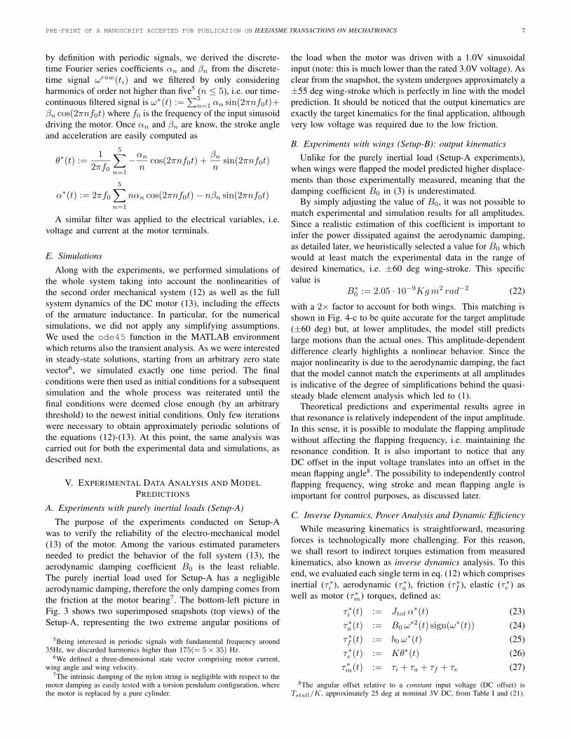
by definition with periodic signals, we derived the discrete-time Fourier series coefficients αn and βn from the discrete-time signal ωraw(ti) and we filtered by only consideringharmonics of order not higher than five5 (n ≤ 5), i.e. our time-continuous filtered signal is ω∗(t) :=
∑5n=1 αn sin(2πnf0t)+
βn cos(2πnf0t) where f0 is the frequency of the input sinusoiddriving the motor. Once αn and βn are know, the stroke angleand acceleration are easily computed as
θ∗(t) :=1
2πf0
5∑n=1
−αn
ncos(2πnf0t) +
βn
nsin(2πnf0t)
α∗(t) := 2πf0
5∑n=1
nαn cos(2πnf0t)− nβn sin(2πnf0t)
A similar filter was applied to the electrical variables, i.e.voltage and current at the motor terminals.
E. Simulations
Along with the experiments, we performed simulations ofthe whole system taking into account the nonlinearities ofthe second order mechanical system (12) as well as the fullsystem dynamics of the DC motor (13), including the effectsof the armature inductance. In particular, for the numericalsimulations, we did not apply any simplifying assumptions.We used the ode45 function in the MATLAB environmentwhich returns also the transient analysis. As we were interestedin steady-state solutions, starting from an arbitrary zero statevector6, we simulated exactly one time period. The finalconditions were then used as initial conditions for a subsequentsimulation and the whole process was reiterated until thefinal conditions were deemed close enough (by an arbitrarythreshold) to the newest initial conditions. Only few iterationswere necessary to obtain approximately periodic solutions ofthe equations (12)-(13). At this point, the same analysis wascarried out for both the experimental data and simulations, asdescribed next.
V. EXPERIMENTAL DATA ANALYSIS AND MODELPREDICTIONS
A. Experiments with purely inertial loads (Setup-A)
The purpose of the experiments conducted on Setup-Awas to verify the reliability of the electro-mechanical model(13) of the motor. Among the various estimated parametersneeded to predict the behavior of the full system (13), theaerodynamic damping coefficient B0 is the least reliable.The purely inertial load used for Setup-A has a negligibleaerodynamic damping, therefore the only damping comes fromthe friction at the motor bearing7. The bottom-left picture inFig. 3 shows two superimposed snapshots (top views) of theSetup-A, representing the two extreme angular positions of
5Being interested in periodic signals with fundamental frequency around35Hz, we discarded harmonics higher than 175(= 5× 35) Hz.
6We defined a three-dimensional state vector comprising motor current,wing angle and wing velocity.
7The intrinsic damping of the nylon string is negligible with respect to themotor damping as easily tested with a torsion pendulum configuration, wherethe motor is replaced by a pure cylinder.
the load when the motor was driven with a 1.0V sinusoidalinput (note: this is much lower than the rated 3.0V voltage). Asclear from the snapshot, the system undergoes approximately a±55 deg wing-stroke which is perfectly in line with the modelprediction. It should be noticed that the output kinematics areexactly the target kinematics for the final application, althoughvery low voltage was required due to the low friction.
B. Experiments with wings (Setup-B): output kinematicsUnlike for the purely inertial load (Setup-A experiments),
when wings were flapped the model predicted higher displace-ments than those experimentally measured, meaning that thedamping coefficient B0 in (3) is underestimated.
By simply adjusting the value of B0, it was not possible tomatch experimental and simulation results for all amplitudes.Since a realistic estimation of this coefficient is important toinfer the power dissipated against the aerodynamic damping,as detailed later, we heuristically selected a value for B0 whichwould at least match the experimental data in the range ofdesired kinematics, i.e. ±60 deg wing-stroke. This specificvalue is
B∗0 := 2.05 · 10−9Kgm2 rad−2 (22)
with a 2× factor to account for both wings. This matching isshown in Fig. 4-c to be quite accurate for the target amplitude(±60 deg) but, at lower amplitudes, the model still predictslarge motions than the actual ones. This amplitude-dependentdifference clearly highlights a nonlinear behavior. Since themajor nonlinearity is due to the aerodynamic damping, the factthat the model cannot match the experiments at all amplitudesis indicative of the degree of simplifications behind the quasi-steady blade element analysis which led to (1).
Theoretical predictions and experimental results agree inthat resonance is relatively independent of the input amplitude.In this sense, it is possible to modulate the flapping amplitudewithout affecting the flapping frequency, i.e. maintaining theresonance condition. It is also important to notice that anyDC offset in the input voltage translates into an offset in themean flapping angle8. The possibility to independently controlflapping frequency, wing stroke and mean flapping angle isimportant for control purposes, as discussed later.
C. Inverse Dynamics, Power Analysis and Dynamic EfficiencyWhile measuring kinematics is straightforward, measuring
forces is technologically more challenging. For this reason,we shall resort to indirect torques estimation from measuredkinematics, also known as inverse dynamics analysis. To thisend, we evaluated each single term in eq. (12) which comprisesinertial (τ∗i ), aerodynamic (τ∗a ), friction (τ∗f ), elastic (τ∗e ) aswell as motor (τ∗m) torques, defined as:
τ∗i (t) := Jtot α∗(t) (23)
τ∗a (t) := B0 ω∗2(t) sign(ω∗(t)) (24)
τ∗f (t) := b0 ω∗(t) (25)
τ∗e (t) := Kθ∗(t) (26)τ∗m(t) := τi + τa + τf + τe (27)
8The angular offset relative to a constant input voltage (DC offset) isTstall/K, approximately 25 deg at nominal 3V DC, from Table I and (21).

PRE-PRINT OF A MANUSCRIPT ACCEPTED FOR PUBLICATION ON IEEE/ASME TRANSACTIONS ON MECHATRONICS 8
−60 −40 −20 0 20 40 60−0.4
−0.3
−0.2
−0.1
0
0.1
0.2
0.3
0.4
θ [deg]
τ [m
Nm
]
τa
τf
τi +τ
e
28Hz
28Hz
38Hz 38Hz
35Hz
35Hz
43Hz
43Hz
48Hz
48Hz
38Hz
38Hz
Fig. 5. Experimental torque vs. wing angle plot in response to 2.0V inputsinusoids at different (superimposed) frequencies, between 28Hz and 48Hz,with 1Hz step. Elasto-kinetic torques (τi + τe) appear as ‘stretched loops’,labels indicate the loops relative to 28, 35, 38, 43, and 48 Hz. Aerodynamictorques appear as ellipses (the largest occurring at 38Hz, as labeled). Thickerlines indicate resonance conditions, which in our system occurs at 38Hz.
recalling that the asterisk (∗) denotes a truncated Fourier seriescontaining harmonics up to the 5th order.
Once the kinematics is known and the various torqueshave been estimated via inverse dynamics, the instantaneouspower can be estimated as torque times angular velocity. Fordissipative torques, such as aerodynamic damping and motorfriction, the instantaneous power is by definition non-negativeand so is the average power.
When it comes to inertial and elastic torques, the instan-taneous power is the time derivative of the kinetic energy12Jtot ω
∗2 and the elastic energy 12K θ∗2, respectively. There-
fore the average power is identically zero, being both energyfunctions periodic of period T .
In analyzing the ‘fitness’ to fly of hovering animals suchas hummingbirds, both Weis-Fogh [12] and Ellington [17]considered the work done by the muscles without accountingfor its sign. For example, Ellington [17] defines the ‘meaninertial power’ as the work done by muscles to acceleratewings from zero to maximum angular velocity during thefirst half of a half-stroke, i.e. a quarter of period. This isequivalent to the average of the norm of the instantaneouspower, i.e. without considering its sign, which in the case ofinertial torques becomes
P+i =
1
T
∫ T
0
|τi · ω| dt =12Jtot ω
∗2max
4T
We shall here follow a similar approach and consider the normof motor power
P+m =
1
T
∫ T
0
|τm · ω| dt
since, also in the case of artificial ‘muscles’ such as DCmotors, the negative work done by a motor to decelerate awing cannot be efficiently recovered at the electrical port ofthe motor, mainly due to the motor resistance [7].
Weis-Fogh [12] used a very effective graphical represen-tation for computing the average power contributions due to
25 30 35 40 45 500
5
10
15
20
25
30
frequency [Hz]
aero
dyna
mic
pow
er [m
W]
1.0V (exp)1.5V (exp)2.0V (exp)1.0V (sim)1.5V (sim)2.0V (sim)
Fig. 6. Experimental (solid lines) and simulated (dashed lines) averageaerodynamic power at different frequencies and at different input voltagelevels (1.0V, 1.5V, 2.0V, as denoted by the markers).
the different sources (23)−(27). In fact, a simple change ofvariable in the integral∫ T
0
τ · ω(t) dt =∫ θ(T )
θ(0)
τ dθ
suggests that average power can be graphically represented asan area in a torque vs. angle plot. Weis-Fogh used this plot ofevaluate power contribution in the case of quasi-sinusoidal ap-proximations. For more accurate calculations involving higherharmonics, we shall resort to numerical integration althoughthe graphical representation is still very effective to understandwhat happens beyond the quasi-sinusoidal approximation.
Figure 5 shows the torque vs. angle representation of theaerodynamic torque (τa), the friction torque (τf ) and theelasto-kinetic torque (τi+τe), superimposing the experimentalresults in response to input voltage sinusoids with 2.0V ampli-tude and different frequencies (between 28Hz and 48Hz, with1Hz step). The algebraic sum of these components correspondsto the torque provided by the motor, as in (27). The areasunderneath the curves correspond, for each frequency, to theaverage power (times the period T ).
The curves for friction and aerodynamic damping are quasi-elliptical and enclose the largest area at resonance (thickestdashed line), i.e. in presence of larger wing strokes. It is clearhow, near resonance, the power dissipated against aerodynamicdamping is much larger than the one due to motor friction.The average aerodynamic power, for both experimental dataand simulations, is represented in greater details in Fig. 6, fordifferent frequencies and different input voltages.
The curves relative to the elasto-kinetic torque appear inFig. 5 (solid lines) as ‘stretched loops’, rather than elliptical.To explain the origin of such ‘stretched loops’, it is instructiveto see what happens in a quasi-sinusoidal approximation. Inthis ideal case, the angular position (θ) and the angular accel-eration (α) are perfectly in phase, as clear from eq. (5) and(7). This means that, within a quasi-sinusoidal approximation,the elasto-kinetic torque τie is also proportional to the strokeangle, by a factor
τie
θ= K − (2πf0)
2Jtot

PRE-PRINT OF A MANUSCRIPT ACCEPTED FOR PUBLICATION ON IEEE/ASME TRANSACTIONS ON MECHATRONICS 9
25 30 35 40 45 5045
50
55
60
65
70
75
80
85
90
frequency [Hz]
dyna
mic
effi
cien
cy [%
]
1.0V (exp)1.5V (exp)2.0V (exp)1.0V (sim)1.5V (sim)2.0V (sim)
Fig. 7. Experimental (solid lines) and simulated (dashed lines) dynamicefficiency at different input voltages and different frequencies.
It is clear that this proportionality is zero at resonance (14),positive at lower frequencies and negative at higher frequen-cies. In this ideal case, at resonance, the elastic and the inertialtorque perfectly balance one another and the motor has onlyto overcome dissipative torques.
When higher harmonics are introduced, due to the nonlinearaerodynamic damping, the elasto-kinetic torque is no longerperfectly in-phase with the stroke angle, although a linear trendcan still be observed. Nevertheless, the benefits of resonanceare still visible, as the elasto-kinetic power at resonance (areaunderneath the thickest solid line) is still much lower thanthe aerodynamic power (area enclosed by the thickest dashedline).
Remark: The maximum motor torque (thick, solid line inFig. 5) is much smaller than the maximum aerodynamic torque(thick, dashed line in Fig. 5) while, without an elastic string,the inertial torques (entirely provided by the motor) would befive times larger, as shown previously.
The benefits of resonance are best captured by the so-calleddynamic efficiency, defined as [12]
ηdynamic :=Pa
P+m
=
∫ T
0τ∗a · ω∗ dt∫ T
0|τ∗m · ω∗| dt
(28)
which, at larger wing strokes, reaches values close to 90% forboth experimental data and simulations, as shown in Fig. 7.
The dynamic efficiency is a measure of optimality whichdoes not include the actuator properties. Therefore, it isimportant to analyze which percentage of the input powerPV I (e.g. coming from a battery), can be dissipated againstthe aerodynamic damping. This is what we here call overallefficiency and define as
ηoverall :=Pa
PV I=
∫ T
0τ∗a · ω∗ dt∫ T
0Vm · Im dt
(29)
The input power, for all frequencies and input voltages, isrepresented in Fig. 8. It should be noticed how, at resonance,while the wing-stroke increases, the input power actuallydecreases. The overall efficiency is plotted, for all frequenciesand input voltages, in Fig. 9. Firstly, it should be noticed thatin the best scenario, i.e. when the load impedance matches
30 35 40 450
50
100
150
200
250
frequency [Hz]
inpu
t pow
er [m
W]
1.0V (exp)1.5V (exp)2.0V (exp)1.0V (sim)1.5V (sim)2.0V (sim)
Fig. 8. Experimental (solid lines) and simulated (dashed lines) average inputpower at different input voltages and different frequencies.
the load, we cannot hope for more than 50% overall efficiencysince, as the remaining 50% of power is dissipated in the motorarmature resistance. Secondly, the actual matching condition(thick, dashed line in Fig. 2) is not optimal as predicted fromthe catalog data (thick, solid line in Fig. 2). This leads to anoverall efficiency of nearly 17% for the largest wing-strokes,at resonance.
25 30 35 40 45 500
2
4
6
8
10
12
14
16
18
20
frequency [Hz]
over
all e
ffici
ency
[%]
1.0V (exp)1.5V (exp)2.0V (exp)1.0V (sim)1.5V (sim)2.0V (sim)
Fig. 9. Experimental (solid lines) and simulated (dashed lines) overallefficiency at different input voltages and different frequencies.
D. Flapping wings without the benefits of resonance
To test the ability of the motor to flap wings withoutthe benefits of mechanical resonance, the elastic string wasremoved and the motor was driven with a sinusoidal voltageat 38Hz, with the same voltage amplitude used in previoussection, i.e. 1.0V, 1.5V and 2.0V. As expected, the motoris unable to produce large wing motions. Figure 10 showssnapshots of the output wing stroke which, at the maximuminput voltage is no larger than ±17 deg at 2.0 V.
As a note, since the string was removed, there was noequilibrium point and the average position drifted from trialto trial.

PRE-PRINT OF A MANUSCRIPT ACCEPTED FOR PUBLICATION ON IEEE/ASME TRANSACTIONS ON MECHATRONICS 10
1.0V 1.5V 2.0V
Fig. 10. Output wing motion without an elastic element in response to inputsinusoids at 38Hz and at different voltage levels. The top view snapshots weretaken with a webcam, the wing stroke angle can be inferred by the blurring.
E. Suitability for autonomous vehicles
The platform shown in Fig. 4-b is meant for characteriza-tion. Nylon strings are used as torsion springs to guaranteelinearity of the stiffness coefficient at relatively large angulardisplacements and to be able to easily adjust the values ofstiffness to our needs by simply selecting appropriate stringlengths.
Of course, a different implementation would be requiredfor a future, autonomous flying vehicle. In this sense, totest the potentiality of our approach, we also developed acompact and lightweight device, see Fig. 11, which showssimilar performance as the one used for characterization. Themain difference with the prototype in Fig. 4-b is in the elasticstructure, implemented with compact helical springs (MISUMIwire spring, model no. WFH4-5) attached between the rotorshaft and the stator.
A second difference is that we are now using two motorsto implement proper wing flapping (in the setup in Fig. 4-b, the two wings are always coplanar). In fact, a single,larger wing is attached to each motor which can be flappedat the cost of some additional friction at the motor bearings,due to centrifugal axial loading, with minimal degradation ofperformance. The operation of such a device is shown in theattached video, where the two motors are driven in parallelby a single amplifier. Alternatively, the each motor could bedriven by a different amplifier, leading to different kinematicsfor the left and right wings, useful from a control perspective.
Another possibility would be having two motors, each driv-ing two coplanar wings (as in our original setup in Fig. 4-b), toimplement an X-Wings configuration which has been provedto be very effective in capturing clap-and-fling aerodynamiceffects [18].
VI. DISCUSSION
In this section we aim to discuss our results, also in relationto conventional approaches.
A. Second order systems and nonlinearities
The behavior of our system is described by the second orderdifferential equation (12) where the nonlinearity is solely dueto the damping term (second term of the left-hand side), whilethe inertial and elastic terms (respectively, the first and the lastterm of the left-hand side) are linear. Linearity of the inertialterm is guaranteed by the direct drive while linearity of the
Wing Wing
shaft-spring-wing coupler
helical
spring
helical
spring
DCM
fixture
DCM
Fig. 11. New prototype with independent wings. Further details can be foundin the supplementary video attachment.
elastic term is a consequence of implementing torsion springsvia long and thin wires.
A first property of systems such as the one in eq. (12)is that the resonant frequency is relatively independent ofthe nonlinear damping, as shown by our model prediction aswell as experimental measurements at different input voltageamplitudes, in Fig. 4-c. This is not the case when the elasticterm is nonlinear, which might give rise to undesirable ‘jumpphenomena’ and resonant frequency shifts, documented forexample in [19].
A second property of systems such as the one in eq. (12) isthat, despite the nonlinear damping, solutions still maintain aquasi-sinusoidal regime, at least for sinusoidal forcing inputs,allowing for AC steady-state ‘quick estimates’ as in [12].Unlike direct drive, slider crank mechanisms suffer from aninherent nonlinearity in the inertial term which reduces thebenefits of resonance due to the non-negligible presence ofhigher order harmonics, as shown in [7].
B. Power considerations for motor selectionDC motors are rated by manufacturers based on DC steady
state operating conditions, i.e. assuming that voltage (V),current (I), speed (ω) and torque (T) are constant. Operationallimits provided by manufacturers are mainly meant to preventoverheating of the motor which is directly related to theaverage power, not the instantaneous power. For DC steadystate, average power can be evaluated directly as the productof constant variables such as V I or Tω. At AC steadystate, the average power depends on the amplitude but alsoon the phase difference. For example, the average electricalpower is evaluated as 1
2V0I0 cosΦ, where V0 and I0 are theamplitude of AC voltage and AC current, respectively, and Φis the phase difference between them. The 1
2 factor in the ACpower formula means that the maximum operating conditionsfor variables such as, for example, voltage and current canhave peak values higher than the nominal values, i.e. thanthose rated by the manufacturer at the DC steady-state case,before exceeding the ultimate power limits which would causeoverheating.
Remark: However, when operating at AC steady state, evenbefore overheating might occur, current amplitudes beyond thenominal DC values might lead to magnetic saturation.
As for our selected motor (line ‘6’, in Fig. 2), the rated339 mW maximum power (Pmax in Tab. I) clearly exceeds

PRE-PRINT OF A MANUSCRIPT ACCEPTED FOR PUBLICATION ON IEEE/ASME TRANSACTIONS ON MECHATRONICS 11
the required 30mW (minimum level of the top U-shapedcurve). This means that, in principle, a smaller motor wouldalso be suitable but none of the lighter motors in Tab. Imeets the 30mW requirement, except for motor ‘4’ whichhowever displays very little safety margin in Fig. 2 (especiallyconsidering that actual parameters might differ from the valuesstated in the manufacturer’s catalogue, as for motor ‘6’)
It is interesting to notice how motor ‘3’ is actually suf-ficiently powerful (88mW) but does not pierce the 30mWcurve due to an impedance mismatch. A possible solutionwould be to design an appropriate linear transmission (e.g.gear-head system) to ensure impedance matching, equivalentto shifting line ‘3’ rightwards in Fig. 2. Such a solution would,of course, increase complexity and reduce efficiency and willbe addressed in future work.
C. Potential benefits with respect to conventional approaches
The main difference with conventional approaches basedon nonlinear transmissions, such as slider-crank mechanisms,is in the reciprocating motion of the motor itself. A clearadvantage of our approach is in the reduction of complexity:besides a motor and a wing we only need a spring, makingthe system very robust and inexpensive. In our case, exploitingresonance is a necessity as it would be highly inefficient, if notimpossible, to generate large wing-strokes at high-frequencywithout an elastic mechanism storing and releasing energy, asshown in Section V-D. Conventional approaches do not requirean elastic mechanism although they would indeed benefit fromresonance [7]. However, due to inherent nonlinearities, thebenefits of resonance cannot be fully exploited and it wouldbe very interesting to compare, on a fair ground, the twoapproaches in terms of efficiency.
So far, we are only aware of the work of Baek et al. [7]on incorporating the energetics of voltage-driven DC motorsin the overall analysis. However, to the authors’ knowledge,an explicit efficiency analysis and a methodology for motorselection is still missing. Such an analysis is complicated byseveral factors. In our case, ‘quick estimates’ (based on ACregime analysis) inspired by the work of Weis-Fogh [12] onflapping animal species, was possible because of the quasi-sinusoidal properties of the wing trajectories (a consequenceof having nonlinearities only in the damping as mentionedearlier in this section). The regime analysis of DC motor drivenslider-crank mechanisms must rely on numerical solutions, asspeed and torque profiles are far from being quasi-sinusoidal[7].
Another advantage we see in our approach is that wecan independently control wing-beat, wing-stroke and meanflapping angle, with potential benefits for controllability ofa two-winged platform [10]. For slider crank mechanisms,only wing-beat can be controlled while wing-stroke and meanflapping angle are fixed. Having frequency as the sole control-lable parameter might lead to disadvantages especially whenresonance is used to boost efficiency. A change in voltageamplitude, for purposes of control, would induce a change infrequency and therefore the system might end up operatingout of resonance.
VII. CONCLUSION
In this paper, we experimentally demonstrated that DCmotors, in concert with an elastic mechanism, can be used todirectly drive flapping wings at large wing-stroke and at highfrequencies. The major novelty of our approach, to the authors’knowledge, is in that the DC motor undergoes a reciprocating(i.e. back and forth) rather than rotary motion. Whenever areciprocating motion has to be generated from a DC motor,typical approaches make use of crank-arm mechanisms to turnthe motor rotation into wing flapping. Crank arm mechanismsunavoidably introduce nonlinear kinematics, which stronglylimits the application of the bio-inspired principle of me-chanical resonance as a means of relieving the motor fromexcessive inertial loading. The use of a direct transmissionand of an elastic mechanism ensures that the sole nonlinearityin the mechanical system (12) is in the aerodynamic damping.Resonance is still very effective in this type of nonlinearsecond order system since solutions are ‘quasi-sinusoidal’ andcondition (14) implies that inertial and elastic torques balanceone another, as in the case of linear systems.
In fact, besides mechanical resonance, ‘quasi-sinusoidal’motion is the second important lesson learned from biology.The method based on ‘quick estimates’, as proposed by Weis-Fogh [12] to analyze the fitness to fly of several species, wasreadapted to DC motors, generalizing the maximum powertransfer theorem to nonlinear systems at quasi-sinusoidalregime [14]. The aerodynamic damping of a given wing, at agiven desired kinematics, is captured by the amplitude of theangular velocity Ω0, defined in (8), and can be representedas an equivalent impedance Rmech in the electrical domain,defined as in (18). The DC motor is then selected by match-ing its armature resistance directly with the equivalent wingimpedance.
In conclusion, we developed a prototype which served asproof-of-concept. The selected motor was in fact able to drivethe given wing at the desired kinematics, keeping well withinthe rated limits. The same task was clearly impossible whenthe elastic element was removed, as shown in Fig. 10. Al-though our work focused on miniature flying robots, the sameconcepts can be potentially extended to other applicationswhere quasi-cyclic motions are important, such as running,swimming, hopping robots.
As future work, although this novel method seems po-tentially useful in flying/hovering robots applications, furtherinvestigation is still required. In fact, so far, we only movedair and did not generate any lift. This was purposely done bysetting the wing at a 90 deg angle of attack, in order to facemaximum drag conditions. To be able to generate lift, we shallintroduce an extra degree of freedom to allow wing rotation.Whether active or passive, this extra degree of freedom willinfluence the motor. In particular, a second order descriptionas in (12) will no longer be sufficient. Up to which extent themotor selection method will still be valid in this new scenarioshall also be investigated. Furthermore, although suitable for‘quick estimates’ of the power to be handled by a motor, ourapproach rests on simplified aerodynamic models. Especiallyif wing rotation is allowed in addition to flapping, complexity
PRE-PRINT OF A MANUSCRIPT ACCEPTED FOR PUBLICATION ON IEEE/ASME TRANSACTIONS ON MECHATRONICS 12
behind lift generation mechanisms might require numericalsolvers, based on Navier-Stokes formulation, to provide betterestimates.
ACKNOWLEDGMENT
This work was supported by the MINDEF-NTU-JPP/10/05project funded by the Ministry of Defence, Singapore.
REFERENCES
[1] J. Ayers, J. L. Davis, and A. Rudolph, Eds., Neurotechnology forBiomimetic Robots. MIT Press., 2002.
[2] Y. Kawamura, S. Souda, S. Nishimoto, and C. P. Ellington, “Clapping-wing micro air vehicle of insect size”, in Bio-mechanisms of Swimmingand Flying: Fluid Dynamics, Biomimetic Robots, and Sports Science,N. Kato and S. Kamimura, Eds. Springer, 2008, ch. 3, pp. 319–330.
[3] D. Lachat, A. Crespi, and A. J. Ijspeert, “BoxyBot: a swimming andcrawling fish robot controlled by a central pattern generator”, in Proc.The First IEEE/RAS-EMBS International Conference on BiomedicalRobotics and Biomechatronics (BIOROB’06), Pisa, Tuscany, Italy, Feb.20–22, 2006, pp. 643–648.
[4] T. Weis-Fogh, “Energetics of hovering flight in hummingbirds and indrosophila”, J. Exp. Biol., vol. 56, no. 1, pp. 79–104, 1972.
[5] T. Yasuda, I. Shimoyama, and H. Miura, “Microrobot actuated by avibration energy field”, Sensor. Actuat. A-Phys., vol. 43, no. 3, pp. 366–370, May 1994.
[6] A. Cox, D. Monopoli, D. Cveticanin, M. Goldfarb, and E. Garcia, “Thedevelopment of elastodynamic components for piezoelectrically actuatedflapping micro-air vehicles”, J. Intel. Mat. Syst. Str., vol. 13, pp. 611–615, Sep. 2002.
[7] S.S. Baek, K.Y. Ma, and R.S. Fearing, “Efficient resonant drive offlapping-wing robots”, in Proc. IEEE/RSJ International Conference onIntelligent Robots and Systems (IROS’09), St. Louis, USA, Oct. 11–15,2009, pp. 2854–2860.
[8] http://www.delfly.nl/[9] Z. A. Khan and S. K. Agrawal, “Design of flapping mechanisms based
on transverse bending phenomena in insects”, in Proc. IEEE Interna-tional Conference on Robotics and Automation (ICRA’06), Orlando,USA, May 15–19, 2006, pp. 2323–2328.
[10] L. Schenato, D. Campolo, and S. Sastry, “Controllability issues inflapping flight for biomimetic micro aerial vehicles (MAVs)”, in Proc.IEEE Conference on Decision and Control (CDC’03), vol. 6, Maui,USA, Dec. 9–12, 2003, pp. 6441–6447.
[11] R. Madangopal, Z. A. Khan, and S. K. Agrawal, “Biologically inspireddesign of small flapping wing air vehicles using four-bar mechanismsand quasi-steady aerodynamics”, J. Mech. Des-T. ASME, vol. 127, pp.809–816, Jul. 2005.
[12] T. Weis-Fogh, “Quick estimates of flight fitness in hovering animals,including novel mechanisms for lift production”, J. Exp. Biol., vol. 59,no. 1, pp. 169–230, Aug. 1973.
[13] L. Zhao, Q. Huang, X. Deng, and S. P. Sane, “Aerodynamic effects offlexibility in flapping wings”, J. R. Soc. Interface, vol. 7, no. 44, pp.485–497, Mar. 2010.
[14] D. Campolo, “Motor selection via impedance-matching for drivingnonlinearly damped, resonant loads”, Mechatronics, vol. 20, no. 5, pp.566–573, Aug. 2010.
[15] S. L. Lindstedt, T. E. Reich, P. Keim, and P. C. Lastayo, “Do musclesfunction as adaptable locomotor springs?”, J. Exp. Biol., vol. 205, no.15, pp. 2211–2216, Aug. 2002.
[16] http://www.precisionmicrodrives.com/[17] C. P. Ellington, “The aerodynamics of hovering insect flight. VI. lift
and power requirements”, Philos. T. Roy. Soc. B, vol. 305, no. 1122, pp145–181, Feb. 1984.
[18] F. van Breugel, Z. E. Teoh, and H. Lipson, “A passively stable hoveringflapping micro-air vehicle”, in Flying Insects and Robots, D. Floreano,J.-C. Zufferey, M. V. Srinivasan, C. Ellington, Eds. Berlin Heidelberg:Springer-Verlag, 2009, ch. 13, pp. 171–184.
[19] M. Sitti, D. Campolo, J. Yan, and R.S. Fearing, “Development of PZTand PZN-PT based unimorph actuators for micromechanical flappingmechanisms”, in Proc. IEEE International Conference on Robotics andAutomation (ICRA’01), Seoul, Korea, May 21–26, 2001, pp. 3839–3846.