AEROELASTIC BEHAVIOUR OF A GYROPLANE ROTOR IN AXIAL DESCENT AND FORWARD FLIGHT

State-Space Rotor Aeroelastic Modeling for Real-Time Helicopter Flight Simulation
Riccardo Gori1,a, Francesca Pausilli1, Marilena D. Pavel2 and Massimo Gennaretti1
1Università Roma Tre, Via della Vasca Navale 79, Roma, Italy
2TU Delft, Delft, Netherlands
Keywords: Reduced-order model, Rotor aeroelasticity, State-space modeling, Flight simulation
Abstract. This paper introduces a new approach for the identification of linear state-space models
of dynamical systems of arbitrary complexity. The identification procedure is described and applied
for modeling aeroelastic response of helicopter main rotors. With the aim of developing a tool that
might be conveniently applied for real-time simulations of helicopter flight dynamics, the state-
space model considered is a reduced-order description of loads transmitted to the airframe due to
hub motion and blade pitch controls. In order to validate the proposed approach, loads from the
state-space, reduced-order model are compared with those predicted by the complete full-state,
nonlinear rotor model for prescribed helicopter maneuvers.
Introduction
This work deals with presentation and assessment of a novel procedure for the identification of
linear, state-space, reduced-order models (ROMs) representing aeroelastic response of helicopter
main rotors, with the aim of developing an accurate, as well as fast, helicopter model suitable for
real-time, flight dynamics simulations. It is of general validity and might be extended to
applications concerning nonlinear dynamical systems of arbitrary complexity.
Helicopter flight simulation is a challenging task that has been capturing the attention of industry
and academia since long time. Strong motivations come from the training community, with the
requirement of creating an illusion of reality for pilots to experience. The purpose is achieved when
suited fidelity of flight simulation is reached, which in turn requires real-time, accurate predictions.
Although traditional approach to flight simulation relies on empirical, test-based models, an
increasing interest has emerged on physics-based modeling, thanks to the significant development
of computational technologies [1, 2].
Main rotor aeroelastic behavior strongly affects the overall helicopter dynamics. It is the result
of coupling of complex phenomena; among these, it is worth mentioning the nonlinear dynamics of
the slender blade structure and the complex aerodynamic environment given by combination of
blade periodic motion and inflow induced by wake vorticity remaining in close proximity of the
rotor disk, or even coming in contact with it. Hence, accurate helicopter main rotor aeroelastic
response prediction is a nonlinear, time-periodic, coupled problem, for which real-time simulation is
a very hard task.
The rotor aeroelastic modeling proposed here aims at overcoming this limitation. The starting
point of the proposed model consists in the linear time invariant (LTI) state-space, reduced-order
modeling presented by some of the authors, through which it is possible to predict the complex
rotor aeroelastic behavior in the neighborhood of a given flight condition [3, 4]. This formulation
yields hub forces and moments generated by the rotor (and transmitted to the airframe) as functions
of both hub motion and rotor blade controls. However, it is not adequate for predicting rotor
aeroelastic responses within the whole flight envelope of interest for flight simulation purposes
(namely, when pilot controls and helicopter motion cannot be considered as small perturbations
with respect to a reference flight condition).
Advanced Materials Research Vol. 1016 (2014) pp 451-459
© (2014) Trans Tech Publications, Switzerland
doi:10.4028/www.scientific.net/AMR.1016.451

In order to overcome such limit of applicability, here it is proposed a methodology conceiving
the rotor state-space ROM as consisting of a database of models identified for a given finite set of
flight conditions within the flight envelope that might be of interest, to be interpolated during
helicopter flight dynamics simulations. Each element of the aeroelastic operator database is labeled
with a set of flight parameters that suitably characterize the rotor behavior, whose variation during a
simulated maneuver drives the change of the LTI, state-space rotor ROM to be applied.
Crucial issues affecting the possibility of simulating flight in real-time are the number of states
included to describe the rotor aeroelasticity and the numerical efficiency of the interpolation process.
Recent research work available in the literature has dealt with the problem of real-time operation
and robustness with respect to parameter changes of ROMs devoted to flight simulation of aircraft,
proposing novel numerically efficient ROM adaptation methods that rely on pre-computed ROM
databases [5-7].
Next section gives a description of the methodology applied for identification of the LTI, state-
space models collected in the aeroelastic operator database, as well as, an outline of the approach
suggested for model interpolation at arbitrary flight conditions. Then, results of a numerical
investigation aiming at validating the proposed model for real-time simulation purposes are
presented. They include the prediction of the aeroelastic response of the main rotor of the Bo-105
lightweight helicopter during a decelerated descent maneuver.
Model description
The proposed aeroelastic rotor modeling for unsteady maneuvering simulation is inspired to the LTI,
state-space, ROM presented by some of the authors in Ref. [4]. It is a perturbation model relating
hub forces and moments, Hf , generated by the rotor to hub motion and rotor blade controls, x ,
through the following differential form
H H0 2 1 0= + δ + δ + δ +
= + δ
f f A x A x A x Cr
r Ar B x (1)
where x denotes hub motion and blade control perturbation with respect to a reference trim flight
condition state 0x , at which hub loads 0Hf hold. In addition, , , , ,2 1 0A A A B C are real, fully
populated matrices, whereas A is a block diagonal matrix of the poles related to the (internal)
dynamics of the additional states, r [3, 4]. In our problem, these additional states represent
dynamics of rotor blade degrees of freedom and of wake inflow on rotor disk. For a given trim
flight condition, Eq. 1 is derived starting from a suited sequence of rotor aeroelastic responses to
periodic perturbations within a prescribed range of frequencies, indicated by the characteristic
dynamics of the problem under examination [4]. The model identification process is independent on
the aeroelastic solver applied, but the accuracy of the identified model depends on it.
In order to apply the described aeroelastic rotor model for the simulation of an arbitrary
helicopter maneuver, as the operating conditions change along the trajectory, it is necessary to apply
stepwise updates of the matrix coefficients appearing in Eq. 1. The frequency of these updates
depends on the rate of variation of flight conditions. In principle, this can be obtained by an
interpolation procedure within a suited database that provides instantaneous values of matrices in
Eq. 1, for specific rotor flight parameters occurring during the unsteady maneuver. The database can
be generated through evaluation of matrices in Eq. 1 for a given set of operating trim conditions
(characterized by appropriate rotor flight parameters like advance ratio, thrust coefficient and tip-
path-plane angle, for instance) within the flight envelope.
Accurate and regular interpolation of differential model in Eq. 1 is not a straightforward task. As
explained in Appendix A, matrices , , , , ,2 1 0A A A A B C identified following the procedure
presented in Refs. [3, 4], might provide a discontinuous database, thus yielding inaccurate
interpolations. For this reason, a new model identification approach is developed with the aim of
Mechanical and Aerospace Engineering V452
obtaining a smooth variation of model matrices within the range of operating condition to be
considered.
Akin to the modeling procedure presented in Refs. [3, 4], the proposed approach consists in: first,
the frequency-response functions, kH , involved in the aeroelastic model are sampled by
application of a time-marching aeroelastic solver for a given set of frequencies and operating
conditions within the flight envelope of interest, and then the following optimization problem is
solved
2
, ,
ˆ mink i j k i j
i j k
J H p , H p , (2)
In the above equation, ip denotes the set of rotor flight parameters considered, j is the set of
harmonic response sampling frequencies, whereas ˆkH denotes the approximated form of the k-th
transfer function. Coherently with the differential form of Eq. 1, all transfer functions involved in
the aeroelastic operator are approximated through the following matrix compact form
12ˆ ,i 2 1 0p = + j + j
H A A A C I A B (3)
with the matrices appearing in Eq. 3 that depend on flight parameters, ip . This dependence is
analytically approximated through linear combinations of b-spline functions [8]. The advantage in
using these interpolating functions lies in the possibility of adopting optimal sets of input data
locations in the space of parameters, that allow best fitting of matrix coefficients variation (for
instance, in our kind problems, input data are conveniently concentrated near hovering flight
condition, where the gradient of transfer functions is expected to be relevant).
The coefficients of b-splines combinations expressing matrix entries are the variables to be
identified by solution of the optimization problem in Eq. 2. The total number of them is usually of
the order of thousands. For this reason, the minimization problem is formulated as a nonlinear least-
square problem with separable variables [9], solved by means of a gradient based method (see
Appendix A for further details).
Numerical results
The numerical investigation carried out in this work has two main objectives: (i) validation of the
state-space rotor aeroelastic model proposed, and (ii) examination of its capability to predict loads
transmitted to the airframe by a helicopter main rotor during maneuvers. To these purposes, a
helicopter configuration representative of the lightweight Bo-105, with a four-bladed, hingeless
main rotor, is considered.
The state-space, aeroelastic ROM is identified by application of the interpolation procedure
described above within the flight envelope defined by flight parameters 0 ,80V kn kn and
21 ,3sh ; 25 transfer function samples (input data locations) are used.
Harmonic responses are evaluated through application of a rotor aeroelastic tool. Rotor blades
structural dynamics is simulated by a nonlinear, bending-torsion, beam-like formulation derived
from that presented in Ref. [10], valid for straight, slender, homogenous, isotropic, non-uniform,
twisted blades, undergoing moderate displacements [11, 12]. Distributed aerodynamic loads are
evaluated through the quasi-steady approximation of the Greenberg sectional theory [13], with
three-dimensional effects from wake vorticity taken into account through wake inflow given by the
boundary integral approach for potential flows presented in Ref. [14]. The set of aeroelastic integro-
partial differential equations derived by coupling blade structural dynamics equations with
aerodynamic loads modeling are spatially integrated through the Galerkin approach [11, 15].
Validation of state-space ROM identification process. First, the accuracy of the presented
methodology in identifying the LTI, finite-state, main rotor representation for operational conditions
Advanced Materials Research Vol. 1016 453

included in the considered flight parameters domain is examined. Figure 1 presents examples
concerning the effect of flight parameters, V and sh , on aeroelastic transfer functions amplitude.
In particular, in Fig. 1a it is shown the amplitude of the transfer function relating thrust force to
pitching angular velocity, for three different flight speeds, whereas Fig. 1b depicts the amplitude
of the transfer function relating rolling moment to blade collective pitch control, for three values of
the rotor shaft angle of attack. For all examined cases, the results obtained by ROM solutions are
compared with those directly identified through the aeroelastic numerical tool. These results reveal
that the considered transfer functions present a remarkable sensitivity to flight velocity, whereas
they are less affected by shaft angle variations. The influence of both velocity and shaft angle is
non-uniformly dependent on frequency. Further, these figures demonstrate the high level of
accuracy of the interpolation process proposed.
In order to appreciate the sensitivity of identified model coefficients on flight parameters
variation, Fig. 2 shows the location on the complex plane of the aeroelastic poles (eigenvalues of
matrix A in Eqs. 1 and 3), for forward flight ranging from 0 kn to 80 kn (Fig. 2a), and shaft angle
changing from 21 to 3 (Fig. 2b). It is worth noting that damping of poles is particularly
affected by flight parameters variation, while their frequency remains almost unchanged.
[a] thrust .vs pitching rate [b] roll moment .vs collective pitch
Fig. 1 Transfer functions variation with respect to forward velocity and shaft angle. Sampled vs
interpolated amplitude frequency distribution.
[a] flight velocity effect [b] shaft angle effect
Fig. 2 Influence of flight parameters on poles of identified aeroelastic ROM.
Mechanical and Aerospace Engineering V454

Then, Fig. 3 shows the comparison between transfer function identified through the proposed
ROM and those obtained with the complete, full-state, nonlinear model, for a flight condition not
included in the database set. In particular, Fig. 3a depicts the transfer function between hub roll
moment and lateral cyclic pitch control, for forward flight velocity V = 30kn, whereas Fig. 3b
presents the transfer function between thrust and collective pitch, for advancing velocity V = 50kn
(in both cases, 7.5sh ). The very good correlation shown in Fig. 3 between interpolated
transfer functions and results directly given by the aeroelastic solver is a prove of the capability of
the presented ROM to accurately estimate system aeroelastic response for arbitrary flight conditions
inside the flight envelope of interest, which is an essential factor for the successful application of
the proposed method in flight simulations.
Application of ROM to maneuvering flight. Next, the performance of the proposed main rotor
model in predicting hub loads during maneuvering flights is assessed. First, it is applied to provide
hub loads response to a periodic cyclic lateral pitch (with 1 rad/s frequency and 1-degree amplitude)
and associated airframe motion (helicopter flight dynamics is perturbed from steady rectilinear,
uniform, level flight with V = 40kn). In Fig. 4 state-space, ROM predictions are compared with
those given by the nonlinear, time-marching solution (NLTM) provided by the rotor aeroelastic tool
also used for evaluation of harmonic responses needed to identify the model. More relevant hub
forces and moments from ROM simulation appear to be in good agreement with those determined
by NLTM analysis, whereas some limited discrepancies are observed between (small-amplitude)
lateral forces.
[a] thrust .vs collective pitch, V=50kn [b] roll moment .vs lat cyclic pitch, V=30kn
Fig. 3 Comparison between interpolated and sampled transfer functions for flight conditions not
included in the database.
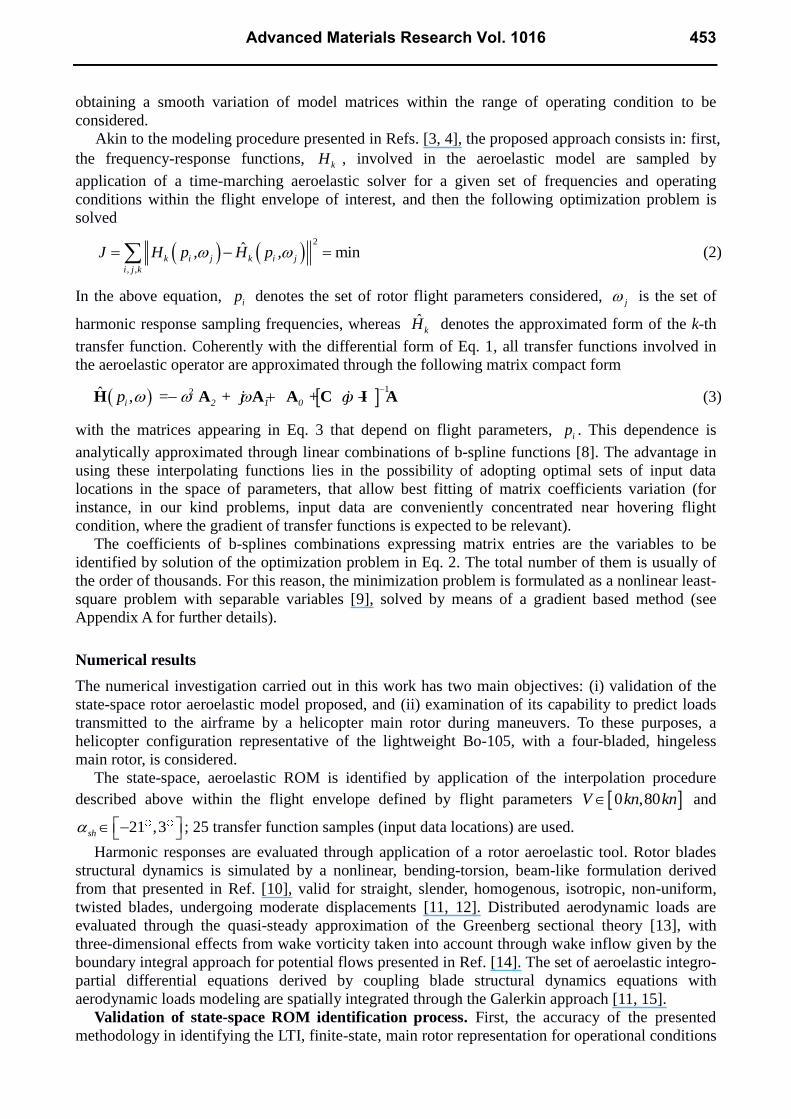
Finally, the state-space, ROM is applied to evaluate hub forces and moments generated by main
rotor during a more complex unsteady Bo-105 maneuver. Starting from a steady level flight
condition, the helicopter model follows a descent trajectory, initially at constant velocity and then
operating a decelerated flight (Fig. 5 depicts time histories of forward velocity, V , and shaft
angle, sh ). Corresponding hub motion and blade pitch controls, previously determined through a
flight dynamics solver with lower-order rotor aeroelastic modeling, are used as input in this
validation analysis. The capability of the proposed state-space ROM to accurately predict hub loads
arising in unsteady helicopter maneuvering is assessed by comparison with loads given by NLTM
solution. The corresponding results are presented in Fig. 6, which shows correlations of time
histories of hub force and moment components (Figs. 6a and 6b, respectively) during the same time
interval of analysis considered in Fig. 1 to illustrate V and sh evolutions. These results
demonstrate that the proposed rotor LTI, state-space ROM is able to yield aeroelastic responses in
Advanced Materials Research Vol. 1016 455

good agreement with those provided by complex, full-state, nonlinear aeroelastic tools, and thus it
seems to be a good candidate for application in helicopter flight simulators, for which maneuver
high-performance computations are required.
Concluding remarks
Development and accuracy assessment of a helicopter main rotor aeroelastic ROM aimed at real-
time maneuvering flight simulations have been presented. It is based on a LTI, state-space matrix
representation of hub loads generated by hub motion and pilot blade pitch controls, combined with a
suited optimization process that allows the identification of model matrices for any flight condition
within the flight envelope of interest, starting from a pre-defined matrix database. The numerical
investigation has demonstrated the capability of the modeling process presented to identify with an
excellent level of accuracy main rotor aeroelastic transfer functions, in any operational condition
within the flight envelope considered. Moreover, the application of the proposed state-space ROM
for evaluating main rotor loads transmitted to the airframe during arbitrary unsteady maneuvers has
provided results in good agreement with those predicted directly by the complex, full-state,
nonlinear, time-marching aeroelastic solver. Although limited to a couple of arbitrary maneuvers,
these outcomes indicate that the presented rotor model seems to be suited for application in
helicopter flight simulators. However, the achievable computational performance of the
methodology needs further investigation, in order to examine its actual capability of real-time
predictions.
[a] hub forces [b] hub moments
Fig. 4 Response to periodic lateral cyclic pitch. ROM vs NLTM.
[a] advance ratio [b] shaft angle
Fig. 5 Time histories of flight parameters during maneuver.
Mechanical and Aerospace Engineering V456
[a] hub forces [b] hub moments
Fig. 6 Time histories of hub loads during maneuver flight. ROM vs NLTM.
Appendix A
The proposed helicopter main rotor aeroelastic state-space ROM is based on the evaluation of
harmonic responses within a prescribed range of frequencies and flight parameters (that characterize
the database). Many approaches have been proposed in the literature to identify the model matrix
coefficients in Eqs. 1 and 3 that, for a single flight condition, provide the best approximation of
sampled transfer functions (see, for instance, Ref. [16]). However, when a further interpolation
among the set of flight conditions considered in the database is required, it is found that the
sequential interpolation procedure (i.e., interpolation of ROMs at several flight conditions,
following frequency response approximations) yields inaccurate results. This phenomenon can be
explained observing that ROM coefficients should be considered as defined in a confidence interval,
because of possible inaccuracies arising in the process leading to their definition. Coefficient
uncertainty inside this interval has a negligible effect on the overall quality of ROM, for a single
flight condition [3, 4]. However if the estimate of ROM coefficients is sought for an arbitrary flight
condition starting from those evaluated for a given set of flight conditions, the interpolated solution
is affected by uncertainties present in the database. Moreover, matrices B and C are not uniquely
defined, and hence if they are identified by independent frequency-domain approximations, their
variation with respect to flight parameters may be not regular and consequently accurate
interpolation is not achievable.
To solve these critical issues, the presented approach proposes to formulate the ROM
approximation problem as a unique optimization problem, where the variables to be identified are
the b-spline coefficients through which the variation of model matrices with flight parameters is
defined [8]. In other words, a nonlinear regression is carried out in a space defined by the frequency
range of frequency responses available and by the range of flight parameters considered,
considering the transfer functions approximation given by Eq. 3, with model coefficients variation
with respect to flight parameters expressed through combination of splines.
A fundamental condition to be satisfied to obtain accurate model interpolations is that the
number of variables of the unique problem is strictly less than the sum of the number of variables of
single approximations that would be introduced in the sequential interpolation problem. If this
condition were not met, then the optimal solution of the unique problem would coincide with the
solution given by the sequential solver. Reducing the variables space is a mean to impose a smooth
variation of the coefficients, while solving the issues related to the not uniqueness of B and C
matrices.
Advanced Materials Research Vol. 1016 457

Of course, the solution of an optimization problem comprising all interpolation variables at the
same time poses a bigger numerical challenge, with respect to solving a set of separate smaller
interpolation problems. For this reason, a dedicated minimization procedure is developed, which
improves the convergence speed and the numerical stability of the method. This procedure consists
in separating the variables the objective function, J, depends linearly on, from those it depends
nonlinearly on [9]. Then, the linear problem is solved using a linear least square approach, whereas
the nonlinear least square problem is solved using a gradient based quasi-Newton method [17].
References
[1] R.W. Du Val: A Real-Time Multi-Body Dynamics Architecture for Rotorcraft Simulation. In
Proceedings of Royal Aeronautical Society and American Helicopter Society International
Conference on The Challenge of Realistic Rotorcraft Simulation. London, UK (2001).
[2] G.D. Padfield and M.D. White: Flight Simulation in Academia HELIFLIGHT in its First Year of
Operation at the University of Liverpool. The Aeronautical Journal, Vol.107, No.1075 (2003),
pp. 529-538.
[3] R. Gori, J. Serafini, M. Molica Colella and M. Gennaretti: Assessment of a State-Space
Aeroelastic Rotor Model for Rotorcraft Dynamics Analysis. In Proceedings of XXII AIDAA
Conference. Napoli, Italy (2013).
[4] J. Serafini, M. Molica Colella and M. Gennaretti: A Finite-State Aeroelastic Model for
Rotorcraft-Pilot Coupling Analysis. CEAS Aeronautical Journal, Vol.5, No.1 (2013), pp. 1-11.
[5] D. Amsallem and C. Farhat: Interpolation Method for Adapting Reduced-Order Models and
Application to Aeroelasticity. AIAA Journal, Vol. 46, No. 7 (2008), pp. 1803-1813.
[6] M. Ghoreyshi, K.J. Badcock and M.A. Woodgate: Accelerating the Numerical Generation of
Aerodynamic Models for Flight Simulation. Journal of Aircraft, Vol. 46, No. 3 (2009), pp. 972-
980.
[7] D. Amsallem, J. Cortial and C. Farhat: Toward Real-Time Computational-Fluid-Dynamics-
Based Aeroelastic Computations Using a Database of Reduced-Order Information. AIAA
Journal, Vol. 48, No. 9 (2010), pp. 2029-2037.
[8] L. Piegl and W. Tiller: The NURBS book. (Springer-Verlag, Berlin 1997).
[9] G.H. Golub and V. Pereyra: The Differentiation of Pseudo-Inverses and Nonlinear Least Square
Problems Whose Variables Separate. SIAM Journal on Numerical Analysis, Vol.10, No.2
(1973), pp. 413-432.
[10] D.H. Hodges and E.H. Dowell: Nonlinear Equation for the Elastic Bending and Torsion of
Twisted Nonuniform rotor Blades. NASA TN D-7818 (1974).
[11] M. Gennaretti and G. Bernardini: Aeroelastic response of helicopter rotors using a 3D unsteady
aerodynamic solver. The Aeronautical Journal, Vol. 110, No. 1114 (2006), pp. 793-802.
[12] M. Gennaretti, M. Molica Colella and G. Bernardini: Prediction of Tiltrotor Vibratory Loads
with Inclusion of Wing-Proprotor Aerodynamic Interaction. Journal of Aircraft, Vol. 47, No. 1
(2010), pp. 71-79.
[13] J.M. Greenberg: Airfoil in Sinusoidal Motion in a Pulsating Stream. NACA TN-1326 (1947).
[14] M. Gennaretti and G. Bernardini: Novel Boundary Integral Formulation for Blade-Vortex
Interaction Aerodynamics of Helicopter Rotors. AIAA Journal, Vol. 45, No. 6 (2007), pp. 1169-
1176.
Mechanical and Aerospace Engineering V458

[15] G. Bernardini, J. Serafini, M. Molica Colella and M. Gennaretti: Analysis of a Structural-
Aerodynamic Fully Coupled Formulation for Aeroelastic Response of Rotorcraft. Aerospace
Science and Technology, Vol. 39, No. 6 (2013), pp. 1-28.
[16] L. Morino, F. Mastroddi, R. De Troia, G.L. Ghiringhelli and P. Mantegazza: Matrix Fraction
Approach for Finite-State Aerodynamic Modeling. AIAA Journal, Vol. 33. No. 4 (1995), pp.
703–711.
[17] D.F. Shanno: Conditioning of Quasi-Newton Methods for Function Minimization.
Mathematics of Computation, Vol. 24, No. 111 (1970), pp. 647-656.
Advanced Materials Research Vol. 1016 459
Copyright © 2022 FDOKUMEN