Unsteady aeroelastic behaviors of rigid airfoils with preset angles of attack
14
http://jvc.sagepub.com/ Journal of Vibration and Control http://jvc.sagepub.com/content/early/2014/06/27/1077546314537106 The online version of this article can be found at: DOI: 10.1177/1077546314537106 published online 30 June 2014 Journal of Vibration and Control Y Bichiou, AO Nuhait, A Abdelkefi and MR Hajj Unsteady aeroelastic behaviors of rigid airfoils with preset angles of attack Published by: http://www.sagepublications.com can be found at: Journal of Vibration and Control Additional services and information for http://jvc.sagepub.com/cgi/alerts Email Alerts: http://jvc.sagepub.com/subscriptions Subscriptions: http://www.sagepub.com/journalsReprints.nav Reprints: http://www.sagepub.com/journalsPermissions.nav Permissions: http://jvc.sagepub.com/content/early/2014/06/27/1077546314537106.refs.html Citations: What is This? - Jun 30, 2014 OnlineFirst Version of Record >> at Virginia Tech on June 30, 2014 jvc.sagepub.com Downloaded from at Virginia Tech on June 30, 2014 jvc.sagepub.com Downloaded from
Transcript of Unsteady aeroelastic behaviors of rigid airfoils with preset angles of attack

http://jvc.sagepub.com/Journal of Vibration and Control
http://jvc.sagepub.com/content/early/2014/06/27/1077546314537106The online version of this article can be found at:
DOI: 10.1177/1077546314537106
published online 30 June 2014Journal of Vibration and ControlY Bichiou, AO Nuhait, A Abdelkefi and MR Hajj
Unsteady aeroelastic behaviors of rigid airfoils with preset angles of attack
Published by:
http://www.sagepublications.com
can be found at:Journal of Vibration and ControlAdditional services and information for
http://jvc.sagepub.com/cgi/alertsEmail Alerts:
http://jvc.sagepub.com/subscriptionsSubscriptions:
http://www.sagepub.com/journalsReprints.navReprints:
http://www.sagepub.com/journalsPermissions.navPermissions:
http://jvc.sagepub.com/content/early/2014/06/27/1077546314537106.refs.htmlCitations:
What is This?
- Jun 30, 2014OnlineFirst Version of Record >>
at Virginia Tech on June 30, 2014jvc.sagepub.comDownloaded from at Virginia Tech on June 30, 2014jvc.sagepub.comDownloaded from
XML Template (2014) [26.6.2014–11:04am] [1–13]//blrnas3/cenpro/ApplicationFiles/Journals/SAGE/3B2/JVCJ/Vol00000/140118/APPFile/SG-JVCJ140118.3d (JVC) [PREPRINTER stage]
Article
Unsteady aeroelastic behaviors of rigidairfoils with preset angles of attack
Y Bichiou1, AO Nuhait2, A Abdelkefi1 and MR Hajj1
Abstract
The effects of varying the angle of attack on the flutter speed and limit cycle oscillations of an aeroelastic system are
investigated. This system consists of a plunging and pitching rigid airfoil supported by linear springs. The unsteady vortex
lattice method is used to model the unsteady flow. The objective is to determine how the flutter boundary is affected by
changing the angle of attack. To solve simultaneously and interactively the governing equations, an iterative scheme based
on Hamming’s fourth order predictor–corrector model is employed. Several numerical simulations are conducted for
various angles of attack to determine their effects on the dynamic behavior of the aeroelastic system and particularly on
the dynamic stability or flutter speed and the nonlinear response of the system. The results show that the flutter speed
increases as the angle of attack is increased. It is also determined that increasing the preset angle of attack results in a
decrease in the dynamic amplitudes of the nonlinear response. In other words, increasing the angle of attack offers a way
to control the system in terms of delaying flutter and reducing the limit-cycle oscillations amplitudes.
Keywords
Aeroelastic system, angle of attack, unsteady vortex lattice method, Hopf bifurcation
1. Introduction
Flutter is a classical phenomenon that is encountered inthe design of aircraft, where it is set as a criterion forflutter boundary. Although flutter has rarely been asso-ciated with the failure of wind turbines, it is expected tobecome more relevant as larger and more flexible bladesare used. As such, determining the flutter boundary forthese blades will become more relevant. The flutterboundary is usually predicted under the assumptionof zero angle of attack (Theodorsen, 1935). Althoughfull unsteady aerodynamics are required to account forphase-related wake effects and the added mass, thequasi-steady approach has been most commonly usedto predict the flutter boundary (Conner et al., 1997;Gilliat et al., 2003; Abdelkefi et al., 2011; 2012).Noting that airfoils in aircraft wings and turbineblades usually have a preset angle of attack, it is ofsignificant importance to determine the effects of thepreset angle of attack on the flutter boundary. To deter-mine the flutter speed analytically, the aeroelasticsystem is perturbed around an equilibrium position.In cases where the angle of attack is preset to a specificvalue, the equilibrium position is different from that ofan airfoil having a zero angle of attack. Particularly,
there is a mean lift associated with a mean circulation inthe wake exhibited by the difference in the maximumand minimum levels of shed vorticity. This difference,albeit small for small values of the angle of attack,introduces a weak nonlinearity in the aerodynamicforces that is associated with the equilibrium position(preset angle of attack) and that could not be accountedfor directly by Theodorsen’s function usually used todetermine flutter on an airfoil with zero angle of attack.The response of a perturbed nonlinear system is a func-tion of the equilibrium position (Nayfeh and Mook,1979). As such, one may expect the aeroelastic responseand flutter boundary to depend on the preset angle ofattack if the change in the aeroelastic system’s state
1Department of Engineering Science and Mechanics, Virginia Polytechnic
Institute and State University, Blacksburg, Virginia, USA2Department of Mechanical Engineering, King Saud University, Riyadh,
Saudi Arabia
Corresponding author:
MR Hajj, Department of Engineering Science and Mechanics, MC 0219,
Virginia Polytechnic Institute and State University, Blacksburg, Virginia
24061, USA.
Email: [email protected]
Received: 8 May 2013; accepted: 29 June 2013
Journal of Vibration and Control
1–13
! The Author(s) 2014
Reprints and permissions:
sagepub.co.uk/journalsPermissions.nav
DOI: 10.1177/1077546314537106
jvc.sagepub.com
at Virginia Tech on June 30, 2014jvc.sagepub.comDownloaded from

XML Template (2014) [26.6.2014–11:04am] [1–13]//blrnas3/cenpro/ApplicationFiles/Journals/SAGE/3B2/JVCJ/Vol00000/140118/APPFile/SG-JVCJ140118.3d (JVC) [PREPRINTER stage]
equilibrium, caused by the nonlinear wake effects, isincluded in the analysis.
To date, there have not been many studies that havefocused on the effect of the angle of attack on the sta-bility of airfoils. Patil et al. (1999) determined the flutterspeed and frequency of a HALE wing for two differentequilibrium positions, namely undeformed anddeformed states. They showed that, in the presence ofa static deformation due to gravity and aerodynamicforces, there is a rapid change in the flutter speed atlow values of the preset angles of attack. They alsodemonstrated that the flutter speeds of deformedstates are much lower than that of the undeformedstate. They explained these results by the presence ofa wing bending for deformed configurations and hencethe presence of structural nonlinearities, which, in turn,change the aeroelastic characteristics of the wing. Attaret al. (2002) performed a theoretical and experimentalinvestigation of the effects of a steady angle of attackon the flutter speed of a plate model of a delta wing.Given that their theoretical model contained only struc-tural nonlinearities and that the aerodynamic loadswere determined using the linear version of the vortexlattice method, they concluded that the flutter speed isvaried when the preset angle of attack is changed.Based on their proposed theoretical models, theyshowed that the presence of a preset angle of attackresults in the appearance of a static position and add-itional stiffness that leads to an increase in the torsionfrequency, and therefore the flutter speed is increasedfor small values of preset angles of attack.
The objective of this work is to quantify the effects ofvarying the preset angle of attack of a two-dimensionalwing on its dynamic instability or flutter speed (classicalflutter) and the amplitudes of the ensuing limit cycleoscillations (LCOs). By quantifying these effects, onecould derive an analytical representation for the vari-ation of the flutter speed with the preset angle of attack.Such a representation can be very helpful for perform-ing analytical optimization. To this end, the two-dimensional nonlinear unsteady vortex lattice method(UVLM) is used to model the unsteady aerodynamicloads on a wing with different preset angles of attack.An iterative scheme, based on Hamming’s fourth orderpredictor–corrector model, is employed to solve inter-actively and simultaneously the coupled governingequations. In Section 2, a representation of the aero-elastic system is presented. Details of the implementa-tion of both the aerodynamic loads and predictor–corrector scheme are presented in Sections 3 and 4,respectively. In Section 5.1, a linear analysis is per-formed to determine the effects of varying the presetangle of attack on the flutter speed. A nonlinear ana-lysis is performed in Section 5.2 to investigate the non-linear response of the aeroelastic system when varying
the preset angle of attack. A summary and conclusionsare presented in Section 6.
2. Representation of the aeroelasticsystem
The aeroelastic system is modeled as a rigid airfoil thatis allowed to move with two degrees of freedom,namely the plunge (h) and pitch (�) motions, asshown in Figure 1. The elastic axis e is defined at adistance x� from the airfoil center of gravity CG anda distance a from the mid-chord, as described inFigure 2. The airfoil is supported by linearly varyingflexural and torsional springs and subjected to a uni-form freestream velocity. Both discrete springs areattached to the wing at the elastic axis located at adistance a from the midchord point. The value of a isconsidered positive when the elastic axis is set behindthe midchord point toward the trailing edge.
Two reference frames are used to describe themotion of the airfoil; one is fixed to the ground (G-F), XY, and the other is fixed to the body (B-F), xy,as shown in Figure 2. Both frames are right handed andthe coordinates system XY is assumed fixed and
Figure 1. Schematic of the aeroelastic system.
Figure 2. Coordinate systems: xy local coordinate system, XY
global coordinate system.
2 Journal of Vibration and Control
at Virginia Tech on June 30, 2014jvc.sagepub.comDownloaded from

XML Template (2014) [26.6.2014–11:04am] [1–13]//blrnas3/cenpro/ApplicationFiles/Journals/SAGE/3B2/JVCJ/Vol00000/140118/APPFile/SG-JVCJ140118.3d (JVC) [PREPRINTER stage]
inertial, while the coordinates system xy is allowed totranslate and rotate, and hence it is not inertial. The Xaxis points to the right while the Y axis points upward.Furthermore, the x axis points toward the trailing edge.The airfoil is allowed to translate in the Y direction andto rotate about the elastic axis in the XY plane. Theplunging and rotation motions are respectively denotedby h and �. The plunge h is considered positive upwardand the pitch � is considered positive clockwise.
Using Lagrange’s equations, the equations ofmotion for this system are written as (Nuhait andMook, 2010)
m €h�mbx� €� cos �0 þ �ð Þ þmbx� _�2 sin �0 þ �ð Þ þ Khh
¼ N cos �0 þ �ð Þ
ð1Þ
Ie €� �mbx� €h cos �0 þ �ð Þ þ K�� ¼M ð2Þ
where, m is the mass per unit length, b the semi chord,x� the position of the center of gravity relative to theelastic axis, �0 the preset angle of attack, Ie the airfoilmass moment of inertia about the elastic axis, Kh thestiffness of the plunge spring, K� the torsional springstiffness, N the aerodynamic normal force, and M theaerodynamic moment.
3. Aerodynamic model
The flow, around the airfoil, is assumed to be two-dimensional, incompressible, and inviscid. All variablesare written in their dimensionless form by scaling allparameters with the speed characterizing the motionof the wing U, the physical length of a bound element l,the characteristic time l
U, and the density of air �1. Thedimensionless variables are then written as
V ¼V�
U, x ¼ x�
l
U, � ¼
��
Ul, r ¼
r�
l, CP ¼
1
2
p�
�1U2
ð3Þ
where V,x,�, r, and CP denote reduced velocity, angu-lar velocity, velocity potential, position vector, andpressure coefficient, respectively. The asterisk is usedto denote the physical quantities. In the UVLM, therigid wing and its wake are represented by sheets ofvorticity as shown in Figure 3. The sheet representingthe wing has its position specified and is called a‘‘bound vortex sheet’’; a pressure jump may existacross it. The sheet representing the wake, whose pos-ition is not known in advance, deforms freely andassumes a force-free position during the simulation.As a result, it is called a ‘‘free vortex sheet’’ and a pres-sure jump cannot exist across it. The bound and free
vortex sheets are joined along the trailing edge ofthe wing.
The total velocity field induced by these vorticesmust satisfy the continuity equation and the followingfive conditions: (1) the disturbance velocity is zero atinfinity; (2) the no-penetration boundary condition issatisfied on the wing; (3) the total circulation arounda closed fluid line around the wing and its wake is con-served (zero in this case); (4) the so called unsteadyKutta condition is satisfied at the trailing edge of thewing; and (5) the pressure is continuous in the wake.The velocity induced by the discrete vortices is com-puted by using the Biot–Savart law. This velocity isinversely proportional to the square of the distancebetween the vortex and the point where the velocity iscomputed. As such, it is a source of a weak nonlinearitythat is introduced by the aerodynamic model. Knowingthe velocity, the pressure jump across the bound sheet iscomputed by using the unsteady Bernoulli’s equation.The aerodynamic lift and moment are then obtained byintegrating over the chord of the wing. More details canbe found in Nuhait and Zedan (1993).
4. Predictor–corrector scheme
There are five independent dimensionless coefficientsthat are obtained from the governing equations andare used as controlling parameters. These coefficientsare the dimensionless radius of gyration r�, the fre-quency ratio �, the mass ratio �, the position of thecenter of gravity x�, and the position of the elastic axisa. Using these parameters, the governing equations (1)and (2) are rearranged to obtain the following nondi-mensional equations of motion.
€h ¼1
r2� � x�ð Þ2 cos � þ �0ð Þð Þ
2½�r2�x�
Nel
2sin � þ �0ð Þ _�2
�2
Nel
� �2
r2��2 1
V2h� x�r
2�
2
Nel
1
V2cos � þ �0ð Þ�
þ r2�2
Nel
1
��Cn cos � þ �0ð Þ þ x�
2
Nel
2
��Cm cos � þ �0ð Þ
�ð4Þ
Plate and wake votrex sheets
Figure 3. Vortex sheets of plate and its wake.
Bichiou et al. 3
at Virginia Tech on June 30, 2014jvc.sagepub.comDownloaded from

XML Template (2014) [26.6.2014–11:04am] [1–13]//blrnas3/cenpro/ApplicationFiles/Journals/SAGE/3B2/JVCJ/Vol00000/140118/APPFile/SG-JVCJ140118.3d (JVC) [PREPRINTER stage]
€� ¼1
r2� � x�ð Þ2 cos � þ �0ð Þð Þ
2
�� x�ð Þ
2sin � þ �0ð Þ cos � þ �0ð Þ _�2
� x�2
Nel
� �3
�21
V2cos � þ �0ð Þh� r2�
2
Nel
� �21
V2�
þ x�2
Nel
� �21
��Cn cos � þ �0ð Þð Þ
2þ2
2
Nel
� �21
��Cm
#
ð5Þ
where c is the chord length, �0 is the preset angle ofattack, Nel is the number of elements in the airfoil, Cn isthe normal force coefficient, and Cm is the momentcoefficient computed from the aerodynamic model.
In order to solve the equations of motion for a givenreduced velocity V, we re-write them as a set of systemof first-order differential equations:
_yj tð Þ ¼ fj t, y1 tð Þ, y2 tð Þ, y3 tð Þ, y4 tð Þð Þ for
j ¼ 1, 2, 3, and 4ð6Þ
where y1ðtÞ ¼ hðtÞ, y2ðtÞ ¼ �ðtÞ, y3ðtÞ ¼ _hðtÞ, y4ðtÞ ¼ _�ðtÞ,f1ðtÞ ¼ _hðtÞ, f2ðtÞ ¼ _�ðtÞ, f3 is the right hand side of equa-tion (4) and f4 is the right hand side of equation (5) withinitial conditions
yj 0ð Þ ¼ �j for j ¼ 1, 2, 3 and 4 ð7Þ
where yj, fj, and �j are the j-components of columnvectors with four components each.
These equations are integrated to find the plungingand pitching responses of the wing. This is an initialvalue problem. The approach followed in this paper isto treat the flowing air and the wing as elements of asingle dynamical system and to integrate all of the gov-erning equations numerically, simultaneously, andinteractively in the time domain starting from giveninitial conditions for the plunge, pitch, and associatedrates (i.e. h(0), �ð0Þ, _hð0Þ, and _�ð0Þ). However, there is afundamental complication with the time-domainapproach chosen to solve the aeroelastic problem. Topredict the aerodynamic loads one must know themotion of the wing, and to predict the motion of thewing one must know the aerodynamic loads. To over-come this complication, an iterative scheme thataccounts for the interaction between the aerodynamicloads and the motion of the wing is employed. Thescheme used in this work is based on Hamming’sfourth-order predictor–corrector method (Carnahanet al., 1969; Ghommem et al., 2012); and hence theadded mass, the added damping, and/or added stiffnesswill not appear explicitly in the equations of motion.The Hamming’s method requires the solution to beknown at three previous time steps and the currentone. As a result, different methods are used to generatethe solution for the first three time steps. For the first
time step, Euler and modified Euler methods are usedas predictor–corrector schemes. For the second timestep, Adams–Bashforth two-step predictor andAdams–Moulton two-step corrector schemes are used.For the third time step, Adams–Bashforth three-steppredictor and Adams–Moulton three-step correctorschemes are used.
5. Results and discussion
In this section, the effects of a preset angles of attack onthe aeroelastic system are shown. An explanation of theobtained behavior is formulated and a relation to theairfoil wake is delivered.
5.1. Linear analysis: effects of the preset angleof attack on the onset of flutter
To determine the reduced flutter speed (i.e. VF), theequations of motion (4) and (5) are linearized andrewritten as follows:
€h ¼c1V2
hþc2V2� þ c3Cn þ c4Cm
h ið8Þ
€� ¼d1V2
hþd2V2� þ d3Cn þ d4Cm
� �ð9Þ
where
c1 ¼ �2
Nel
� �2
r2��2
r2�� x�ð Þ2 , d1 ¼
�x�2
Nel
� �3
�2
r2�� x�ð Þ2
c2 ¼�x�r
2�
2Nel
r2� � x�ð Þ2, d2 ¼
�r2�2Nel
� �2r2� � x�ð Þ
2
c3 ¼r2�
2Nel
1��
r2� � x�ð Þ2, d3 ¼
x�2Nel
� �21��
r2� � x�ð Þ2
c4 ¼x�
2Nel
2��
r2� � x�ð Þ2, d4 ¼
2 2Nel
� �21��
r2� � x�ð Þ2
ð10Þ
Defining the following state variables
X ¼
X1
X2
X3
X4
0BB@
1CCA ¼
h_h�_�
0BB@
1CCA ð11Þ
the equations of motion are rewritten as
_X ¼ A Vð ÞXþ B ð12Þ
4 Journal of Vibration and Control
at Virginia Tech on June 30, 2014jvc.sagepub.comDownloaded from

XML Template (2014) [26.6.2014–11:04am] [1–13]//blrnas3/cenpro/ApplicationFiles/Journals/SAGE/3B2/JVCJ/Vol00000/140118/APPFile/SG-JVCJ140118.3d (JVC) [PREPRINTER stage]
where
A Vð Þ ¼
0 0 1 0
c1V2
0c2V2
0
0 0 0 1
d1V2
0d2V2
0
0BBBBBBBB@
1CCCCCCCCA
ð13Þ
and
B ¼
0
c3CN þ c4CM
0
d3CN þ d4CM
0BBBB@
1CCCCA ð14Þ
In general, the normal force and moment coefficientscan be approximated by
CN ¼ CN �0, �, h, _h� �
¼ e1�0 þ e2X1 þ e3X2
Vþ e4X3 þ . . .
ð15Þ
CM ¼ CM �0, �, h, _h� �
¼ f1�0 þ f2X1 þ f3X2
Vþ f4X3 þ . . .
ð16Þ
Therefore, the equations of motion are rewritten as
_X ¼ A1 Vð ÞXþ B1 ð17Þ
where
A1 Vð Þ ¼
0 0 1 0
c1V2þ c3e2þ c4f2
c3e3þ c4f3V
c2V2þ c3e4þ c4f4 0
0 0 0 1
d1V2þ d3e2þ d4f2
d3e3þ d4f3V
d2V2þ d3e4þ d4f4 0
0BBBBBBB@
1CCCCCCCAð18Þ
and
B1 ¼ �0
0
c3e1 þ c4f1
0
d3e1 þ d4f1
0BBBB@
1CCCCA ð19Þ
For the case of zero angle of attack, the vector B1
becomes null. For this case, Nuhait and Mook (2010)compared the onset of flutter as obtained by usingUVLM and Theodorson’s method. The results
showed that predictions based on the use of UVLMare in agreement with the predictions obtained whenusing Theodorsen’s method. In this work, we use theUVLM to account for the effects of the angle ofattack which impacts the system’s stability throughthe vector B1.
To investigate the effects of the angle of attack onthe dynamic stability or flutter speed, we conductnumerical simulations using the values of the dimen-sionless parameters presented in Table 1. The plottedcurves in Figure 4 show time histories of the plunge andpitch responses for two distinct values of the reducedvelocity, V¼ 2.08 and V¼ 2.10, and when the presetangle of attack is set equal to �0 ¼ 4:58� ¼ 0:04 rad.The amplitudes of both plunge (h) and pitch (�)motions decay with time when the reduced velocity isset equal to 2.08, as shown in Figure 4(a) and (b). Onthe other hand, when increasing the reduced velocity to2.10, the aeroelastic system loses its stability and exhi-bits oscillatory motions, as shown in Figure 4(c) and(d). The frequency of oscillations for both motions isvery high. The amplitudes of the plunge and pitch oscil-lations grow to reach a constant value (i.e. limit-cycleoscillations). The reduced flutter speed, VF, is definedby the speed that causes the aeroelastic system to loseits stability and start having self-excited oscillations.For this system under a zero angle of attack, thereduced flutter speed is between V¼ 2.08 andV¼ 2.10. To determine the exact flutter speed, thereduced velocity is increased progressively fromV¼ 2.08 by increments of 0.005. Figure 5 shows thevariation of the reduced flutter speed with the presetangle of attack. The plots shows that increasing thepreset angle of attack results in an increase in the flutterspeed. A continuous, but small, increase in the reducedflutter speed is observed as the preset angle of attackis increased from 0� to 6�. At the higher preset anglesof attack, the reduced flutter speed increases byabout 7% when the preset angle of attack is increasedfrom 6� to 12�.
Time series of the twist angle, � þ �0, are presentedin Figure 6 when the reduced velocity is set equal to
Table 1. Numerical
parameters of the
aeroelastic system.
Considered
parameters
� 0.6
� 20
r� 0.5
a �0.4
x� 0.2
Bichiou et al. 5
at Virginia Tech on June 30, 2014jvc.sagepub.comDownloaded from

XML Template (2014) [26.6.2014–11:04am] [1–13]//blrnas3/cenpro/ApplicationFiles/Journals/SAGE/3B2/JVCJ/Vol00000/140118/APPFile/SG-JVCJ140118.3d (JVC) [PREPRINTER stage]
(a) (b)
(d)(c)
Time step Time step
Time step Time step
Figure 4. Time histories of the dimensionless plunge and pitch (in radians) motions when the preset angle of attack �0 ¼ 4:58� and
for two different reduced velocities: (a,b) V¼ 2.08 and (c,d) V¼ 2.10.
Figure 5. Variation of the reduced flutter speed VF as a function
of the preset angle of attack �0.
Time step, t
Figure 6. Time series for the twist angle � þ �0 (in radians)
at V¼ 2.05.
6 Journal of Vibration and Control
at Virginia Tech on June 30, 2014jvc.sagepub.comDownloaded from

XML Template (2014) [26.6.2014–11:04am] [1–13]//blrnas3/cenpro/ApplicationFiles/Journals/SAGE/3B2/JVCJ/Vol00000/140118/APPFile/SG-JVCJ140118.3d (JVC) [PREPRINTER stage]
2.05 before the onset of flutter. Three values of thepreset angle of attack are considered (i.e.�0 ¼ 0�, � 5�). The responses corresponding to�0 ¼ �5
� are more damped when compared to theresponses associated to �0 ¼ 0�. Thus, increasing the
magnitude of the preset angle of attack increases thecoupled damping coefficient. The curves plotted inFigure 7(a) show the variations of the coupled dampingcoefficient with the preset angle of attack and reducedvelocity. These plots show that, for a specific reduced
(a) (b)
Figure 7. Variations of (a) the coupled damping coefficient z and (b) dimensionless coupled frequency o with the reduced velocity
for different preset angle of attack �0 for different reduced speeds V.
(a) (b)
(c)
Y
X X
X
Y
Y
Figure 8. Snapshots of the wake over one cycle of oscillation when the reduced velocity V¼ 2.22 for three different values of the
preset angle of attack, (a) �0 ¼ 5�, (b) �0 ¼ 0�, and (c) �0 ¼ �5�. The red and blue dots represent positive and negative vortices as
shed.
Bichiou et al. 7
at Virginia Tech on June 30, 2014jvc.sagepub.comDownloaded from

XML Template (2014) [26.6.2014–11:04am] [1–13]//blrnas3/cenpro/ApplicationFiles/Journals/SAGE/3B2/JVCJ/Vol00000/140118/APPFile/SG-JVCJ140118.3d (JVC) [PREPRINTER stage]
velocity, the coupled damping coefficient increaseswhen increasing the preset angle of attack. The resultsalso show that the zero crossing of the damping coeffi-cient takes place at a higher reduced speed as the angleof attack is increased. Figure 7(b) shows the variationsof the dimensionless coupled frequency with the presetangle of attack and reduced velocity. The plots showthat the coupled frequency decreases when increasingthe preset angle of attack or increasing the reducedvelocity.
5.2. Nonlinear analysis: effects of the presetangle of attack on the nonlinear responseof the system
Plots of the wake for one cycle of oscillations for threedifferent preset angles of attack � ¼ 5�, � ¼ �5�, and� ¼ 0� are presented in Figure 8(a)–(c), respectively.Figure 8 is the complete solution to the aeroelasticsystem of equations 4 and 5. The blue and red dotsare used to respectively represent negative and positivecirculations. The number of shed vortices in all plots isset to the same value of 1500. In Figure 8 (a) and (b),the cycle starts with the maximum value of � þ �0 (i.e.subplots (a)(1) and (b)(1)). However, in Figure 8(c) thecycle starts with the minimum value of � þ �0 (i.e. sub-plot (c)(1)). The plots in Figure 8(a) and (c) are sym-metric relative to the horizontal axis. Furthermore, thevalues of the vorticity obtained in Figures 8(a) and (c)
are opposite to each other. Consequently, consideringpositive or negative preset angles of attack gives thesame results. In the rest of this work, only positivepreset angles of attack are considered.
The effects of the preset angle of attack on the non-linear response of the aeroelastic system are determinedfrom numerical simulations performed at differentvalues of �0 and over a wide range of reduced velocities.The plotted curves in Figure 9 show the bifurcationdiagrams of the dynamic amplitudes of the plunge,pitch, lift coefficient, and moment coefficient forreduced velocities between 2 and 2.25. As predictedfrom the linear analysis, increasing the preset angle ofattack yields an increase in the reduced flutter speed. Itis also noted that the aeroelastic system exhibits a Hopfbifurcation (Nayfeh and Balachandran, 1994) for allconsidered preset angles of attack. Generally a Hopfbifurcation can be either supercritical (safe) or subcrit-ical (dangerous). In the case of a supercritical Hopfbifurcation, increasing the reduced velocity is accompa-nied by a smooth increase in the amplitude of the limit-cycle oscillations. This increase is reversed by decreas-ing the reduced velocity, independently of the initialconditions. In contrast, in the case of a subcriticalHopf bifurcation, there is a jump in the oscillationsamplitude near flutter. In fact, depending on the initialconditions, the system could undergo limit-cycle oscil-lations at speeds below the linearly predicted flutterspeed. In this case, decreasing the reduced velocity
(a) (b)
(d)(c)
Figure 9. Variations of the nondimensional dynamic amplitudes of the (a) plunge hd, (b) pitch �d (in radians), (c) lift coefficient CLd,
and (d) moment coefficient CMdfor different values of the preset angle of attack �0.
8 Journal of Vibration and Control
at Virginia Tech on June 30, 2014jvc.sagepub.comDownloaded from

XML Template (2014) [26.6.2014–11:04am] [1–13]//blrnas3/cenpro/ApplicationFiles/Journals/SAGE/3B2/JVCJ/Vol00000/140118/APPFile/SG-JVCJ140118.3d (JVC) [PREPRINTER stage]
(a) (b)
(d)(c)
Figure 10. Variations of the nondimensional dynamic amplitudes of the (a) plunge, (b) pitch (in radians), (c) lift coefficient, and
(d) moment coefficient as a function of the preset angle of attack �0 for different values of the reduced velocity.
(a) (b)
(d)(c)
Figure 11. Variations of the nondimensional static amplitudes of the: (a) plunge, (b) pitch (in radians), (c) lift coefficient, and moment
coefficient for different values of the preset angle of attack �0.
Bichiou et al. 9
at Virginia Tech on June 30, 2014jvc.sagepub.comDownloaded from

XML Template (2014) [26.6.2014–11:04am] [1–13]//blrnas3/cenpro/ApplicationFiles/Journals/SAGE/3B2/JVCJ/Vol00000/140118/APPFile/SG-JVCJ140118.3d (JVC) [PREPRINTER stage]
does not follow the curve obtained when increasing thisvelocity. By observing that the Hopf bifurcationis smooth, we determine, that for the considered aero-elastic system, at different preset of angles of attack,the bifurcation is of the supercritical type. For thistype, the reduced flutter speed can be computedusing the following expression (Nayfeh andBalachandran, 1994)
VF ¼a2�2V1 � a2�1V2
a2�2 � a2�1ð20Þ
where a�i are amplitudes of the �ðtÞ signal correspond-ing to the velocities V1 and V2 which are near flutter.The flutter speeds as determined in the previous sectionare extremely close or equal to the ones obtained byusing equation (8).
The plotted curves in Figure 9 show that increasingthe reduced velocity results in an increase in thedynamic amplitudes of the plunge, pitch, lift, andmoment coefficients for all considered preset angles ofattack. Moreover, increasing the preset angle of attackis accompanied by a decrease in the dynamic ampli-tudes of the plunge, pitch, lift coefficient, and momentcoefficient, as shown in Figures 9(a)–(d), respectively.
A clearer measure of this effect is shown in Figure 10.These results can be explained by the higher dampingvalues associated with increasing the preset angle ofattack.
The presence of a preset angle of attack changes thegoverning equations and causes the airfoil to assume adifferent static position than that of the zero angle ofattack configuration. These static positions are alsodependent on the reduced velocity and the rest of thesystem’s parameters. Because the system’s parametersare fixed in our work, these static positions are onlydependent on the reduced velocity and preset angle ofattack. These predictions are confirmed in the plottedcurves in Figure 11 which show the variations of thestatic positions of the plunge, pitch, lift, and momentcoefficients as a function of the reduced velocity. Forreduced velocity values that are less than the reducedflutter velocity, an increase in the reduced velocity orthe preset angle of attack results in an increase in thestatic position. The value of this static position reachesits peak at the flutter speed.
To investigate the global behavior of the system andthe effects of the preset angle of attack on the static anddynamic amplitudes, we plot in Figure 12 the rootmean square (RMS) values for the plunge, pitch, lift,and moment coefficients. RMS values are used since for
(a)(b)
(d)(c)
Figure 12. Variations of the nondimensional RMS amplitudes for the: (a) plunge, (b) pitch (in radians), (c) lift coefficient, and
(d) moment coefficient for different values of the preset angle of attack �0.
10 Journal of Vibration and Control
at Virginia Tech on June 30, 2014jvc.sagepub.comDownloaded from

XML Template (2014) [26.6.2014–11:04am] [1–13]//blrnas3/cenpro/ApplicationFiles/Journals/SAGE/3B2/JVCJ/Vol00000/140118/APPFile/SG-JVCJ140118.3d (JVC) [PREPRINTER stage]
higher reduced velocities the response includes morethan one frequency. Inspecting the plotted curves inFigure 12, it is noted that increasing the preset angleof attack is accompanied by an increase in the RMS
amplitudes of the system’s output, except the pitchmotion, as shown in Figure 12(b). Furthermore, theresults show that an increase in the reduced velocity isaccompanied by an increase in the RMS amplitudes of
(a) (b)
(c)
(e) (f)
(g) (h)
(d)
Figure 13. Time series and phase portraits for the (a,e) plunge, (b,f) pitch (in radians), (c,g) lift coefficient, and (d,h) moment
coefficient for the preset angle of attack �0 ¼ 4� and reduced velocity V¼ 2.21.
Bichiou et al. 11
at Virginia Tech on June 30, 2014jvc.sagepub.comDownloaded from
XML Template (2014) [26.6.2014–11:04am] [1–13]//blrnas3/cenpro/ApplicationFiles/Journals/SAGE/3B2/JVCJ/Vol00000/140118/APPFile/SG-JVCJ140118.3d (JVC) [PREPRINTER stage]
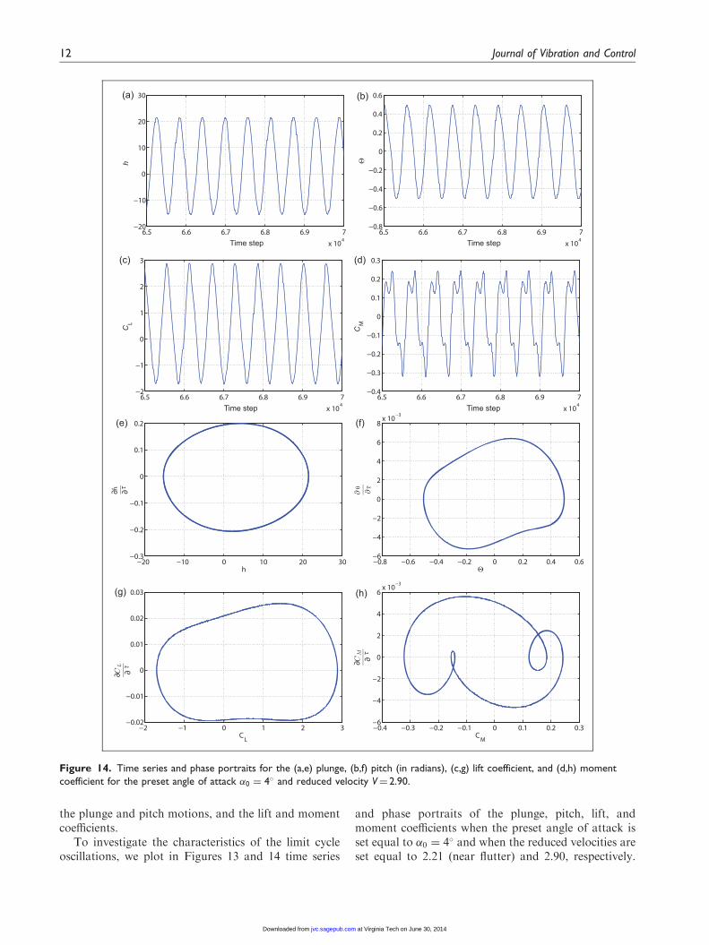
the plunge and pitch motions, and the lift and momentcoefficients.
To investigate the characteristics of the limit cycleoscillations, we plot in Figures 13 and 14 time series
and phase portraits of the plunge, pitch, lift, andmoment coefficients when the preset angle of attack isset equal to �0 ¼ 4� and when the reduced velocities areset equal to 2.21 (near flutter) and 2.90, respectively.
(a) (b)
(d)
(f)
(g) (h)
(e)
(c)
Figure 14. Time series and phase portraits for the (a,e) plunge, (b,f) pitch (in radians), (c,g) lift coefficient, and (d,h) moment
coefficient for the preset angle of attack �0 ¼ 4� and reduced velocity V¼ 2.90.
12 Journal of Vibration and Control
at Virginia Tech on June 30, 2014jvc.sagepub.comDownloaded from

XML Template (2014) [26.6.2014–11:04am] [1–13]//blrnas3/cenpro/ApplicationFiles/Journals/SAGE/3B2/JVCJ/Vol00000/140118/APPFile/SG-JVCJ140118.3d (JVC) [PREPRINTER stage]
The time series response just after flutter (near 2.21) areperiodic and dominated by one frequency component,as shown in Figure 13(a)–(d). This is further confirmedby the phase portraits for all system’s output whichshow characteristics that are typical of those associatedwith a periodic system. At higher reduced velocities, thesystem’s response is more complicated, particularly inthe moment coefficient, as shown in Figure 14(d). Wheninspecting the phase portraits of this coefficient, it isnoted the presence of more than one frequency compo-nent, as shown in Figure 14(h). This is an indication ofa secondary Hopf bifurcation. Thus, as increasing thereduced velocity, the aerodynamic nonlinearity in thecoupled model start having a more pronounced role inthe system’s behavior.
6. Conclusions
An aeroelastic numerical model based on a two-dimen-sional unsteady vortex-lattice method has been devel-oped to investigate the effects of varying the presetangles of attack on the flutter speed and limit-cycleoscillations of rigid airfoils. An iterative scheme basedon Hamming’s fourth order predictor–corrector modelwas employed to solve simultaneously and interactivelythe coupled governing equations. Series of numericalsimulations were performed for various angles ofattack to determine their influence of the dynamicinstability (flutter speed) and nonlinear behavior ofthe system. The results show that the aeroelasticsystem did lose its dynamic stability at higher reducedvelocities when increasing the preset angle of attack.Moreover, it was found that increasing the angle ofattack results in a notable change in the vorticity ofthe wake. It was also demonstrated that increasingthe preset angle of attack results in a decrease in thedynamic amplitudes of the nonlinear response andincreases the static equilibrium position of the airfoil.
Funding
This work was partially supported by the Institute of Critical
Technology and Applied Science (ICTAS).
References
Abdelkefi A, Hajj MR and Nayfeh AH (2012) Sensitivityanalysis of piezoaeroelastic energy harvesters. Intelligent
Material Systems and Structures Journal 23: 1523–1531.
Abdelkefi A, Vasconcellos R, Marques FD, et al. (2011)
Bifurcation analysis of an aeroelastic system with concen-
trated nonlinearities. Nonlinear Dynamics Journal 69:
57–70.Abdelkefi A, Vasconcellos R, Nayfeh AH, et al. (2013) An
analytical and experimental investigation into limit-cycle
oscillations of an aeroelastic system submitted to journal
of nonlinear dynamics. Nonlinear Dynamics Journal 71:
159–173.Attar PJ, Dowell EH and Tang DM (2003) A theoretical and
experimental investigation of the effects of a steady angle
of attack on the nonlinear flutter of a delta wing plate
model submitted to journal of fluid and structures. Fluid
and Structures Journal 17: 243–259.Carnahan B, Luther HA and Wilkes JO (1969) Applied
Numerical Methods. New York: Wiley Publishing.Conner MD, Tang DM, Dowell EH, et al. (1997) Nonlinear
behavior of a typical airfoil section with control surface
freeplay: A numerical and experimental study submitted to
journal of fluids and structures. Fluids and Structures
Journal 11: 89–109.Ghommem M, Abdelkefi A, Nuhait AO, et al. (2012)
Aeroelastic analysis and nonlinear dynamics of an elastic-
ally mounted wing. Sound and Vibration Journal 331:
5774–5787.
Gilliat HC, Strganac TW and Kurdila AJ (2003) An investi-
gation of internal resonance in aeroelastic systems sub-
mitted to journal of nonlinear dynamics. Nonlinear
Dynamics Journal 31: 1–22.Katz J and Plotkin A (2001) Low Speed Aerodynamics.
Cambridge: Cambridge University Press.Nayfeh AH and Balachandran B (1994) Applied Nonlinear
Dynamics. New York: Wiley.Nayfeh AH and Mook DT (1979) Nonlinear Oscillations.
New York: Wiley.Nuhait AO and Mook DT (2010) Aeroelastic behavior of flat
plates moving near the ground submitted to journal of
aircraft. Aircraft Journal 47: 464–474.Nuhait AO and Zedan MF (1993) Numerical simulations of
unsteady flow induced by a flat plate moving near ground
submitted to journal of aircraft. Aircraft Journal 30:
611–617.Patil MJ, Hodges DH and Cesnikz CES (2001) Nonlinear
aeroelasticity and flight dynamics of high altitude long
endurance aircraft submitted to journal of aircraft.
Aircraft Journal 38: 88–94.
Theodorsen T (1935) General theory of aerodynamic instabil-
ity and the mechanism of flutter. NACA Technical
Report. No. 496.
Bichiou et al. 13
at Virginia Tech on June 30, 2014jvc.sagepub.comDownloaded from