
generalised head-discharge-inclination relationship for flow ...
Upload
khangminh22Category
view
1download
0
materials
Article
Optimization of Cutting Data and Tool InclinationAngles During Hard Milling with CBN Tools, Basedon Force Predictions and SurfaceRoughness Measurements
Andrzej Matras * and Wojciech Zebala
Production Engineering Institute, Mechanical Faculty, Cracow University of Technology, Al. Jana Pawła II 37,31-864 Kraków, Poland; [email protected]* Correspondence: [email protected]; Tel.: +48-12-374-3250
Received: 23 January 2020; Accepted: 27 February 2020; Published: 2 March 2020�����������������
Abstract: This work deals with technological considerations required to optimize the cutting data andtool path pattern for finishing the milling of free-form surfaces made of steel in a hardened state. Interms of technological considerations, factors such as feed rate, workpiece geometry, tool inclinationangles (lead and tilt angles) and surface roughness are taken into account. The proposed method isbased on calculations of the cutting force components and surface roughness measurements. A casestudy presented in the paper is based on the AISI H13 steel, with hardness 50 HRC and milling witha cubic boron nitride (CBN) tool. The results of the research showed that by modifications of the feedvalue based on the currently machined cross-sectional area, it is possible to control the cutting forcecomponents and surface roughness. During the process optimization, the 9% and 15% increase inthe machining process efficiency and the required surface roughness were obtained according tothe tool inclination angle and feed rate optimization procedure, respectively.
Keywords: optimization; cutting strategy; hard milling; free-form surface milling; CBN tools
1. Introduction
Cubic boron nitride (CBN) is an extremely hard material with excellent physical and chemicalproperties such as heat resistance, high modulus and weak reaction of other elements [1]. CBN, unlikediamond and due to the lower reactivity with the iron, is suitable for the machining of steel [2]. So,besides the grinding and electrical discharge machining process (EDM), cutting tools made of CBN aresuitable in the production of molds and dies in the hard state, in precise and very precise operations ofroughing [3–6].
Many authors have published their research relating to the machinability of hard materials usingtools from the CBN. Matras et al. [7] machined a part of a spherical surface by using a ball nose cutterwith CBN edges. The three various milling workpieces were analyzed (with hardnesses of 50, 62 and65 HRC). Okada et al. [8] machined the steel with a hardness of 60 HRC with high cutting speed vc,reaching up to 600 m/min by using CBN tools. Aslan [9] obtained a surface with low surface roughness,Ra = 0.32 µm, and high tool life. Wojciechowski et al. [10] proposed a method for the reduction ofcutting forces and the improvement of finish ball end milling efficiency of hardened steel 55NiCrMoV6.
Currently, many researchers perform their experiments for the selection of a technology andproduction system. The authors of publications very often propose computer systems for the selectionof process technology. They are based on criteria related to the workpiece geometry, material hardness,surface roughness and dimensional-shape accuracy. Klocke et al. [11] noted that the grinding issuitable only for the production of parts with a relatively simple geometry. It is possible to use with
Materials 2020, 13, 1109; doi:10.3390/ma13051109 www.mdpi.com/journal/materials

Materials 2020, 13, 1109 2 of 22
materials with a hardness of more than 60 HRC, and enables a low surface roughness of workpieceafter machining. The EDM process is suitable for the treatment of complex geometry parts made ofconducting materials, regardless of their hardness. Navas et al. [12] reported its high dimensionalaccuracy and low surface roughness, but it is characterized by low productivity, which is a majorproblem in its application. However, high speed cutting (HSC) machining conducted with the usageof CBN milling tools is suitable for machining of hard materials with complex geometries, includingthose based on free-form surfaces with low surface roughness, high dimensional precision and highmachining efficiency [13].
Milling of free-form surfaces is an expensive process. In order to improve the efficiency of free-formsurfaces milling, many researchers deal with the optimization of this process. The works presented bythem concern the application of numerical modeling for the process parameters’ optimization. Beno atal. [14] analyzed the main features of ball end milling, and proposed a sequence of steps to identifythe most suitable milling strategy.
Zebala and Plaza [15] proposed a method that minimizes the costs of the free-form surfaces’milling. The presented application of the machining process optimization gives the opportunityto reduce the surface roughness parameters almost twofold and to shorten the machining time byapproximately 17%. In turn, Durakbasa et al. [16] optimized the end milling process parameters forthe surface quality of AISI H13 steel by using the Taguchi method. They determined the effect ofthe feed rate, cutting speed, tool tip radius and tool coating type on surface roughness. Chen et al. [17]machined a flat surface made of steel H13. They investigated only the effect of the tool inclination onthe surface roughness. Similarly, Gao et al. [18] investigated the effect of a spherical cutter inclinationon the shape and surface roughness of a microgroove made on a flat surface. They demonstrated thatthe use of an appropriate tool tilting strategy can significantly reduce surface roughness and improvethe shape of the groove.
Bouzakis et al. [19] proposed a method for optimizing the multi-axis machining of free-formsurfaces. Based on the required surface roughness, they optimized the angle and direction of the toolinclination, radial depth of the cut and the feed speed. In their research, they did not take intoaccount the variability of the shape of the surface being machined. In turn, Ikua et al. [20] developeda mathematical model that allows the calculation of machining error and the values of the cuttingforce components during the milling of concave and convex surfaces with spherical cutters. However,they analyzed only a few selected surface shapes. Scandiffio et al. [21] analyzed the effect of the toolinclination angle, not only on the surface roughness and values of cutting force components, but alsotool wear. During the tests, they worked on a fragment of a circular convex surface made of D6 steelwith a hardness of 60HRC. Without analyzing the variability of the surface’s shape to be machined, theydetermined the optimal value of the tool inclination angle. They also demonstrated the need to developa method that allows this angle to be changed depending on the inclination angle of the workpiece.
Ozturk et al. [22] studied the influence of the cutting tool inclination on the surface roughness andthe values of the cutting forces. Theoretical calculations were verified by means of the experiment. Itwas observed that the lead angle should be kept at a slightly positive value, since application of highervalues of this angle shifts the engagement region to the upper parts of the cutting tool. Negative leadangles may result in tool tip contact. However, the authors [17] determined that for milling H13 steelwith cemented carbide ball nose cutters, the optimal value for the tilt angle is from 40◦ to 20◦ for pullmilling, or 20◦ to 40◦ for push milling, and for the lead angle it is approximately 25◦ for oblique reversmilling. Matras et al. [7] applied ball nose cutters with edges made from CBN for milling hardenedsteel with an optimal lead angle equal to 8◦ and oblique revers milling, for a constant tilt angle equal to0◦. Yao et al. [23] also investigated the effect of the inclination angle of the tool and surface shape on itsroughness. They analyzed four different surface shapes that machined with the “Zig” strategy. Theystated that both the shape of the surface and the direction and angle of the tool influenced the surfaceroughness. The machining should be carried out in such a way as to maintain a constant angle ofthe tool inclination relative to the surface.

Materials 2020, 13, 1109 3 of 22
Saffar et al. [24] used the finite element method (FEM) to calculate the components of the cuttingforce and tool deformation. Material properties were defined based on the Johnson–Cook theory. Theyused the deformation functions, strain rate and temperature of the workpiece, which allowed bettermaterial definition than in the form of constant values of coefficients, which takes place in the case oftheoretical calculations. The usage of simulation based on the FEM also gave the possibility of definingthe non-linear shapes of semi-finished products. They obtained a good match between simulation andexperiment results, which confirmed the usefulness of the proposed method.
The purpose of this paper, regarding the complexity of machining of parts having free-formsurfaces made from hardened materials, is a description of a new optimization method developed bythe authors. It allows one to modify the feed speed, direction and angle of cutting tool inclination,and select the types of tool path diagrams based on the shape variability and roughness of the surfaceafter machining.
The paper is organized as follows: after the introduction, the second section analyzes the reviewof literature in the field of milling of free-form surfaces on CNC machine tools. The third section isdevoted to the proposed optimization method, of which verification is presented in the case studysection (fourth). The research is summarized in the fifth section.
2. Milling of Free-Form Surfaces on Multi-Axis Machine Tools
Multi-axis machining of free-form surfaces carried out with a ball milling tool is a very complexprocess. This is due to complexity and variability of the workpiece shape, kinematics of the cuttingprocess and the shape of the cutting tool. During machining with the use of spherical milling cutters,traces that represent the shape of the used cutting tool are created. Based on previous work [25] forspherical milling cutters, the relationships between: the radius of the spherical part of the tool R,the radial cutting depth ae, the angle of inclination of the surface γ and the cusp height Hc can bewritten as follows (1).
ae =
√8×R×Hc − 4·H2
c × cos(γ) (1)
The relations given above are valid for the case where fz ≤ ae; in the opposite case, the radial cuttingdepth ae parameter in the above equation should be replaced with feed per tooth fz. In addition tothe geometric representation of the tool shape, the geometric microstructure of the surface is influencedby, among others, deflection and wear of the cutting tool, plastic deformation in the decohesion zone,and geometrical errors of the machine tool. This results in the formation of a geometric microstructureof a surface inferior to that which results from the theoretical relationship. This phenomenon isparticularly visible for machining of the hard-to-machine materials like steel in a hardened state, duringwhich large values of the total cutting force components are observed, resulting in large deformations ofthe cutting tool [26]. In order to limit the values of the cutting force and tool deflection, the tool shouldbe as small as possible and have small outriggers [27]. The usage of the inclination of the cutting toolin the form of a spherical cutter has a positive effect on the geometric structure of the surface. Whenmachining with the ball milling cutters, the effective cutting speed is calculated for the effective tooldiameter. Due to the zero effective cutting speed in the tool axis, in order to avoid plastic deformation ofthe machined layer, tool tilting strategies and machining on the five-axis machine tools are applied [28].
With the use of modern CAD/CAM systems, it is possible to design the machining process carriedout, whilst maintaining a constant angle of the cutting tool inclination relative to the normal contour ofthe workpiece fragment.
The tool inclination is used in the direction of the feed, perpendicular to the direction of feed orboth directions at the same time [17]. Figure 1 shows how to define the tool inclination.

Materials 2020, 13, 1109 4 of 22
Materials 2020, 13, x FOR PEER REVIEW 4 of 22
Figure 1. Tool inclination in the feed direction (a) and perpendicular to the feed direction (b).
The cutting tool tilting causes the complexity of the cutting process kinematics, which makes it
possible to cut with [19]:
push–oblique plunge,
push–oblique revers,
pull –oblique plunge,
pull–oblique revers.
The above encompasses; the direction and value of the inclination angle of the cutting tool
influence on the size of a fragment of the cutting edge involved in machining (chipped cutting edge)
[20], chip geometry [19], component values of the cutting force [29], as well as microstructure and
surface roughness of the machined surface [17].
When the rounded part of the tool cuts, the change of the tool inclination angle does not affect
the shape and surface area of the machined layer [17]. On the other hand, the variable geometry of
the machined part influences on the cross-sectional area At. As the inclination angle increases, the
cross-sectional area of the cutting layer decreases. This is illustrated graphically in Figure 2a.
Figure 1. Tool inclination in the feed direction (a) and perpendicular to the feed direction (b).
The cutting tool tilting causes the complexity of the cutting process kinematics, which makes itpossible to cut with [19]:
• push–oblique plunge,• push–oblique revers,• pull –oblique plunge,• pull–oblique revers.
The above encompasses; the direction and value of the inclination angle of the cutting toolinfluence on the size of a fragment of the cutting edge involved in machining (chipped cuttingedge) [20], chip geometry [19], component values of the cutting force [29], as well as microstructureand surface roughness of the machined surface [17].
When the rounded part of the tool cuts, the change of the tool inclination angle does not affectthe shape and surface area of the machined layer [17]. On the other hand, the variable geometryof the machined part influences on the cross-sectional area At. As the inclination angle increases,the cross-sectional area of the cutting layer decreases. This is illustrated graphically in Figure 2a.
In analyzing the shape of the machined surface, changes to the cross-section of the cutting layerand the engagement of the tool edge in cutting occur [23]. For the convex surface, the observedcross-section of the cutting layer and the engagement of the cutting edge β = β1 assume a value lowerthan for the concave surface where β = β1 + β2 + β3. These changes are shown in Figure 2b.

Materials 2020, 13, 1109 5 of 22Materials 2020, 13, x FOR PEER REVIEW 5 of 22
Figure 2. Change of the cutting layer cross-sectional area At during machining of an inclined and
un-inclined surface (a) and surface with different shape (b).
In analyzing the shape of the machined surface, changes to the cross-section of the cutting layer
and the engagement of the tool edge in cutting occur [23]. For the convex surface, the observed cross-
section of the cutting layer and the engagement of the cutting edge = 1 assume a value lower than
for the concave surface where= 1 + 2 + 3. These changes are shown in Figure 2b.
3. An Algorithm of the Selection of the Cutting Data and Tool Inclination Angle
When machining the free-form surfaces on the multi-axis numerical machine tools, despite the
constant cutting parameters, the variable shape of the surface results in the variability of the cross-
cut section, which results in variation of the forces and deterioration of the quality and roughness of
the machined surface. At the same time, it was found that the analyzed literature concerns only a
small scope of the analyzed process. Investigations allow only the selection of constant values of the
technological parameters (cutting speed, feed, radial depth of cut and tool inclination), not taking
into account the variability of the cross-section of the machined part and the shape of the machined
part, occurring during the machining of the free-form surfaces.
In order to additionally take into account the variability of the cross-section of the cutting layer
and the shape of the workpiece, an optimization method was developed. The proposed method is
based on the thesis: During the free-form surface machining on the multi-axis machine tools using
the ball milling cutters, the cross-sectional area changes, and affects the values of the cutting force
components, which cause the deformation of the cutting tool and deterioration of the machined
surface quality. It is possible, by adjusting the proper tool inclination angle, to minimize the values
of the total cutting force components, and then, by modifying the feed rate, to stabilize the values of
the total force components and the cross-sectional area of the cutting layer. Stabilization at the
assumed level of the cutting force components allows for the control of the cutting tool deflection,
which positively affects the quality of the machined surface.
Figure 2. Change of the cutting layer cross-sectional area At during machining of an inclined andun-inclined surface (a) and surface with different shape (b).
3. An Algorithm of the Selection of the Cutting Data and Tool Inclination Angle
When machining the free-form surfaces on the multi-axis numerical machine tools, despitethe constant cutting parameters, the variable shape of the surface results in the variability of the cross-cutsection, which results in variation of the forces and deterioration of the quality and roughness ofthe machined surface. At the same time, it was found that the analyzed literature concerns onlya small scope of the analyzed process. Investigations allow only the selection of constant values ofthe technological parameters (cutting speed, feed, radial depth of cut and tool inclination), not takinginto account the variability of the cross-section of the machined part and the shape of the machinedpart, occurring during the machining of the free-form surfaces.
In order to additionally take into account the variability of the cross-section of the cutting layerand the shape of the workpiece, an optimization method was developed. The proposed method isbased on the thesis: During the free-form surface machining on the multi-axis machine tools usingthe ball milling cutters, the cross-sectional area changes, and affects the values of the cutting forcecomponents, which cause the deformation of the cutting tool and deterioration of the machined surfacequality. It is possible, by adjusting the proper tool inclination angle, to minimize the values of the totalcutting force components, and then, by modifying the feed rate, to stabilize the values of the totalforce components and the cross-sectional area of the cutting layer. Stabilization at the assumed levelof the cutting force components allows for the control of the cutting tool deflection, which positivelyaffects the quality of the machined surface.
In order to implement the proposed method, an algorithm was developed (Figure 3a,b).The proposed method allows one to modify the feed speed, cutting tool angle and tool path pattern. Itwas developed mainly to improve the surface quality and increase the manufacturing efficiency ofthe finishing machining of the molds and matrices.

Materials 2020, 13, 1109 6 of 22
Materials 2020, 13, x FOR PEER REVIEW 7 of 22
the set of NCopt_j codes is reduced by the NCopt code and the procedure is repeated from the place
where the NCopt code is selected. The discussed procedure is presented in the form of algorithms in
Figure 3a,b.
Figure 3. Cont.

Materials 2020, 13, 1109 7 of 22
Materials 2020, 13, x FOR PEER REVIEW 8 of 22
Figure 3. Optimization algorithm: (a) main algorithm; (b) OPK and OSN stage.
4. Case Study
4.1. Material and Experimental Setup
The machining was carried out on a machine tool DMU Ultrasonic 20 linear. Parts with the flat
surfaces with dimensions of 5 × 5 mm made of chromium-molybdenum hot work tool steel (AISI
H13) with a hardness of 50 HRC were machined. The chemical composition of this material is shown
in Table 1. The mechanical properties of the AISI H13 hot work tool steel are presented in Table 2. In
order to verify the proposed method, a free surface formed on the basis of two spline curves was
machined. A spherical milling tool with edges made of CBN (catalog designation
CBN2XLBR0100N050S04) was selected. The geometry of the cutting tool is presented in Appendix A
(Table A1).
Figure 3. Optimization algorithm: (a) main algorithm; (b) OPK and OSN stage.
In the proposed method, the following input data are determined: shape and material of the part,depth of cutting ap, machine tool parameters (working space, feed and spindle speed ranges) andrequirements for the quality of the machined surfaces, which considered the roughness parameters(Ramax, Rzmax) as the limitations of the optimization process.
The optimization method consists of two stages. In the first stage, an optimization of the machiningprocess (OPK) is carried out to determine the nominal values of the cutting parameters (ae_N, fN,δ1_N, δ2_N), enabling the creation of a flat surface with assumed surface roughness parameters(e.g. Ramax, Rzmax) with maximum cutting efficiency Qf_max. Initially, the ranges of variability ofthe analyzed cutting parameters are determined: ae_i, fi, δ1_i, δ2_i for I = 1, . . . ,n. At this stage,the nominal cross-section of the machined layer is also determined and the efficiency of the machiningprocess Qf_i = ae_i · fi [mm2/min] and cutting force components, e.g., Ft_i are calculated. Calculations

Materials 2020, 13, 1109 8 of 22
of the cutting force components are performed using FEM, and they can be optionally replaced bymeasurements. For the purposes of the machining process optimization, a series of experimental testsshould be performed or, if they exist, the available results of the research and the technological basecould be used. After machining, the microgeometry measurements of the machined surfaces (e.g. Rai,Rzi) are performed. A set of the best parameters is chosen, which fulfills the assumed quality criteriaand the highest machining efficiency Qf_max. The nominal force value Ft_N < Ft_max for the machiningof a flat surface by using the inclined tool was calculated. If the experimental tests do not permit one toobtain a surface with the assumed parameters, a new set of cutting parameter ranges is defined andoptionally, another type of cutting tool is typed and the entire procedure is repeated.
In the next step, the geometry of the workpiece is defined and a set of NCj codes is created for j = 1,. . . , m with cutting parameters ae_N, fN, δ1_N, δ2_N. The creation of a series of the NCj codes is intendedto apply various types of tool path diagrams. In the next step, the optimization (OSN algorithm) ofthe generated NCj codes is performed.
Optimization aims align the values of the cutting force components and the cross-section ofthe machined layer by changing the feed rate. It is conducted on the basis of the variation ofthe tangential component value of the total cutting force Ft, resulting from the variation of the machinedsurface shape and machined cross-sectional area At. FEM is used to calculate the force value changes.In the first stage, based on Ft_N, the optimization criterion Ft_max is defined. The force value Ft_max
may be greater than Ft_N to increase the efficiency of the machining process, or less than Ft_N toimprove stability.
Next, the blank is defined, and then a model of the workpiece is discretized to calculate the nextcross sections of the cutting layer At_i (for i = 1, . . . , n), occurring during cutting time with the nominalfeed rate fN.
The optimization is based on the calculation of the feed value fi, which will modify the cross-sectionof the cutting layer At_i and the magnitude of the force Ft_i. In the first stage, the feed rate f is determined,during which the expected force value occurs as Ft_i=Ft_max. Then, the correctness of the calculations ischecked. The force value Ft_i for the new At_i and fi is calculated, on the condition that Ft_i ≤ Ft_max
is checked.If the criterion is fulfilled, the calculations are made for the next cross-section of the machined
layer At_i (i = i + 1). If the condition is not fulfilled, the feed rate is reduced (for example by ∆ = 2%),which reduces the Ft_i force value, and the correctness of the calculations is checked again.
After completing all calculations (i = n) for the defined sections of the cutting layer At_i, the newNCopt_j code is saved and the procedure is performed for the next NCj code (j = j + 1). After optimizingthe entire set of the created codes (j = m), the NCopt code is selected from the NCopt_j codes, the use ofwhich ensures the shortest machining time tmin. The prototype is manufactured and the geometricsurface microstructure measurements are performed. If the prototype with the assumed surface qualityis made (Ra ≤ Ramax, Rz ≤ Rzmax), the procedure is terminated. If the criterion is not fulfilled, the set ofNCopt_j codes is reduced by the NCopt code and the procedure is repeated from the place where the NCopt
code is selected. The discussed procedure is presented in the form of algorithms in Figure 3a,b.
4. Case Study
4.1. Material and Experimental Setup
The machining was carried out on a machine tool DMU Ultrasonic 20 linear. Parts with the flatsurfaces with dimensions of 5 × 5 mm made of chromium-molybdenum hot work tool steel (AISI H13)with a hardness of 50 HRC were machined. The chemical composition of this material is shown inTable 1. The mechanical properties of the AISI H13 hot work tool steel are presented in Table 2. In orderto verify the proposed method, a free surface formed on the basis of two spline curves was machined.A spherical milling tool with edges made of CBN (catalog designation CBN2XLBR0100N050S04) wasselected. The geometry of the cutting tool is presented in Appendix A (Table A1).

Materials 2020, 13, 1109 9 of 22
Table 1. Chemical composition of the hot work tool steel (AISI H13), (%).
C Mn Si Cr Mo V
0.4 0.4 1.0 5.25 1.35 1.0
Table 2. Mechanical properties of the hot work tool steel (AISI H13).
Tensile Strength[MPa]
Thermal Conductivity[W/m◦C]
Density[Kg/m3]
Modulus of Elasticity[GPa] Poisson Ratio
1200 17.6 7750 215 0.27
Recommended cutting data values for the selected tool and workpiece material are presented inTable 3.
Table 3. Recommended cutting data values.
n [rev/min] vc [m/min] ap [mm] ae [mm] f [mm/min] δ1 [◦] δ2 [◦]
27000 150 0.1 0.035 1900 0 10
The cutting tests were carried out at the constant cutting speed and axial depth of cut (vc, ap).The radial cutting depth ae, feed rate f, and the inclination angle of the tool in feed δ1, perpendicular tofeed δ2 directions, were changed. Table 4 presents the values and ranges of the cutting parameters’variation used in the experiments.
Table 4. The range of variation and the values of the adopted cutting process data.
n [rev/min] vc [m/min] ap [mm] ae [mm] f [mm/min] δ1 [◦] δ2 [◦]
27000 150 0.1 0.025–0.1 720–1920 0–18 0–18
During the research, the Taguchi method, based on the L16 orthogonal table for the four inputparameters, was used [30]. Cutting cases were analyzed: push–oblique plunge, push–oblique revers,pull–oblique plunge, pull–oblique revers, and therefore, four sets of sixteen attempts were made.Table 5 presents the Taguchi L16 orthogonal table with values of the analyzed cutting parameters.
Table 5. Taguchi L16 orthogonal table with values of analyzed parameters.
Lp. A B C Dae δ1 δ2 f
[mm] [◦] [◦] [mm/min]
1 4 1 1 1 0.1 0 0 7202 4 2 2 2 0.1 6 6 9603 4 3 3 3 0.1 12 12 14404 4 4 4 4 0.1 18 18 19205 3 1 2 3 0.075 0 6 14406 3 2 1 4 0.075 6 0 19207 3 3 4 1 0.075 12 18 7208 3 4 3 2 0.075 18 12 9609 2 1 3 4 0.05 0 12 1920
10 2 2 4 3 0.05 6 18 144011 2 3 1 2 0.05 12 0 96012 2 4 2 1 0.05 18 6 72013 1 1 4 2 0.025 0 18 96014 1 2 3 1 0.025 6 12 72015 1 3 2 4 0.025 12 6 192016 1 4 1 3 0.025 18 0 1440
Materials 2020, 13, 1109 10 of 22
Using the Taguchi method, the values of S/N (signal to noise) coefficients were determined.The parameters which most strongly influenced the process were sought, and the optimal set of inputparameters was selected. This action allowed the selection of the cutting data, the use of which allowsthe creation of a flat surface with the assumed quality level in the shortest possible time.
The ninth grade of roughness was assumed as a restriction related to the quality of the surface,(Ramax = 0.32 µm, Rzmax = 1.6 µm). The measurements of the surface geometric microstructure weremade using the profilograph Form TalySurf Intra 50. Measurements were made based on norms ISO4287, ISO 25178 and EUR 15178N.
Numerical calculations were applied to predict the values of the total cutting force components.Calculations performed with the use of Finite Element Method have sufficient accuracy to analyze andoptimize machining processes [24,31,32].
In the first stage of the algorithm (OPK) the Johnson–Cook constitutive equation (2) was employedto model the plasticity of the workpiece material. The equation defines the plastic flow stress asa function of plastic strain, strain rate and temperature:
σ = (A + Bεn)
[1 + C ln
( .ε.ε0
)][1−
( T − Tr
T − Tm
)m](2)
Coefficients A, B, n, C, and m represent the initial yield strength, hardening coefficient, strainhardening exponent, strain rate sensitivity, and thermal softening coefficient.
ε, Tr and Tm mean, respectively, the reference strain rate, reference temperature and meltingtemperature of the workpiece. The material constants of the J-C flow stress model for AISI H13 steelare presented in Table 6.
Table 6. Johnson–Cook constitutive model parameters for AISI H13 steel [32].
A MPa B MPa n C m ε
1469 321.39 0.278 0.028 1.18 1.0
Calculations were performed with the support of the AdvantEdge software [33]. The cutting forcemeasurements could be an alternative to the FEM calculations.
The cutting force material model applied in the second stage of the algorithm (OSN) usesEquations (3) and (4).
σn = BC1·hB1·vA1
c − (1− sin(α))C1 (3)
σ f = BC2·hB2·vA2
c − (1− sin(α))C2 (4)
where:σn, σf—normal and frictional pressures on the rake faceh—average uncut chip thicknessvc—cutting speedα —rake angleValues of the material model coefficients are presented in Table 7. Calculations of the cutting
forces were performed with the support of the Production Module software [33].
Table 7. Values of the material model coefficients.
BC1 B1 A1 C1 BC2 B2 A2 C2
4030 0.0058 0 0.6153 0.6021 −0.0031 0 −2.2125

Materials 2020, 13, 1109 11 of 22
Knowledge of the stress, acting in the normal and tangential direction to the surface, enablesthe calculation of the values of the normal and tangential components of the cutting force Fn and Ff (5)acting on the surface S, schematically shown in Figure 4.
Fn =
∫Sσn × dS, =
∫Sσ f × dS (5)
Materials 2020, 13, x FOR PEER REVIEW 11 of 22
𝐹𝑛 = ∫ 𝜎𝑛
𝑆
× 𝑑𝑆, = ∫ 𝜎𝑓
𝑆
× 𝑑𝑆 (5)
Figure 4. The scheme of the forces acting in the cutting zone.
In order to determine the optimal cutting data, the machining efficiency obtained for the
analyzed cutting parameters was calculated (6).
𝑄𝑓 = 𝑎𝑒 ∙ 𝑓 (6)
4.2. Optimization of the Cutting Data and Inclination Angle of the Tool—Stage I (OPK)
As a result of the conducted research, the influence of the analyzed input parameters on the
surfaces roughness was observed. Figure 5 shows the views of the exemplary surfaces obtained as a
result of using different directions of the cutting tool inclination.
Figure 4. The scheme of the forces acting in the cutting zone.
In order to determine the optimal cutting data, the machining efficiency obtained for the analyzedcutting parameters was calculated (6).
Q f = ae· f (6)
4.2. Optimization of the Cutting Data and Inclination Angle of the Tool—Stage I (OPK)
As a result of the conducted research, the influence of the analyzed input parameters on the surfacesroughness was observed. Figure 5 shows the views of the exemplary surfaces obtained as a result ofusing different directions of the cutting tool inclination.
Increasing the feed speed and radial depth of the cut allows the workpiece machining process towork at a higher efficiency Qf, but not all surfaces are of sufficient quality. Analyzing the influenceof the direction and tool inclination angle on the surface roughness, its non-linear character was alsoobserved. The surface quality improves as the value of the tool inclination angle δ1 increases. Inthe case of the angle δ2, the tilt above 12◦ should be used. The influence of the analyzed cuttingparameters on the surface roughness parameters Ra and Rz is shown in Figures 6 and 7.

Materials 2020, 13, 1109 12 of 22Materials 2020, 13, x FOR PEER REVIEW 12 of 22
Figure 5. Isometric views of the exemplary surface roughness made with different tool tilt strategies: (a) Pusch; (b) Pull; (c) Plunge; (d) Reverse, constant parameters n = 27000 rev/min and ae = 0.025 mm.
Increasing the feed speed and radial depth of the cut allows the workpiece machining process to work at a higher efficiency Qf, but not all surfaces are of sufficient quality. Analyzing the influence of the direction and tool inclination angle on the surface roughness, its non-linear character was also observed. The surface quality improves as the value of the tool inclination angle δ1 increases. In the case of the angle δ2, the tilt above 12° should be used. The influence of the analyzed cutting parameters on the surface roughness parameters Ra and Rz is shown in Figures 6 and 7.
Figure 5. Isometric views of the exemplary surface roughness made with different tool tilt strategies:(a) Pusch; (b) Pull; (c) Plunge; (d) Reverse, constant parameters n = 27000 rev/min and ae = 0.025 mm.Materials 2020, 13, x FOR PEER REVIEW 13 of 22
Figure 6. The influence of the analyzed factors on the means values of the surface roughness
parameter Ra.
Figure 7. The influence of the analyzed factors on the means values of the surface roughness
parameter Rz.
Among the analyzed parameters the radial depth of cut ae has the biggest influence on the values
of the parameters Ra and Rz. The angles1 and 2 and the feed rate f have the less impact (Figures 6
and 7) Figures 8 and 9 present the average values of the surface roughness parameters Ra and Rz,
measured for the analyzed machining cases. In appendix B there are Table B1 with average values of
the analyzed surface roughness parameters. After analyzing Figures 8–9, it is possible to determine
the values of the cutting parameters and cutting process kinematics, enabling formation of a flat
surface fragment characterized by surface roughness parameters Ra and Rz fulfilling the assumed
criterion (Ramax i Rzmax).
Figure 6. The influence of the analyzed factors on the means values of the surface roughnessparameter Ra.

Materials 2020, 13, 1109 13 of 22
Materials 2020, 13, x FOR PEER REVIEW 13 of 22
Figure 6. The influence of the analyzed factors on the means values of the surface roughness
parameter Ra.
Figure 7. The influence of the analyzed factors on the means values of the surface roughness
parameter Rz.
Among the analyzed parameters the radial depth of cut ae has the biggest influence on the values
of the parameters Ra and Rz. The angles1 and 2 and the feed rate f have the less impact (Figures 6
and 7) Figures 8 and 9 present the average values of the surface roughness parameters Ra and Rz,
measured for the analyzed machining cases. In appendix B there are Table B1 with average values of
the analyzed surface roughness parameters. After analyzing Figures 8–9, it is possible to determine
the values of the cutting parameters and cutting process kinematics, enabling formation of a flat
surface fragment characterized by surface roughness parameters Ra and Rz fulfilling the assumed
criterion (Ramax i Rzmax).
Figure 7. The influence of the analyzed factors on the means values of the surface roughnessparameter Rz.
Among the analyzed parameters the radial depth of cut ae has the biggest influence on the valuesof the parameters Ra and Rz. The angles δ1 and δ2 and the feed rate f have the less impact (Figures 6and 7) Figures 8 and 9 present the average values of the surface roughness parameters Ra and Rz,measured for the analyzed machining cases. In Appendix B there are Table A2 with average values ofthe analyzed surface roughness parameters. After analyzing Figures 8 and 9, it is possible to determinethe values of the cutting parameters and cutting process kinematics, enabling formation of a flat surfacefragment characterized by surface roughness parameters Ra and Rz fulfilling the assumed criterion(Ramax i Rzmax).Materials 2020, 13, x FOR PEER REVIEW 14 of 22
Figure 8. The average values of the surface roughness parameter Ra measured during the tests.
Figure 9. The average values of the surface roughness parameter Rz measured during the tests.
Figure 10 shows the influence of the analyzed factors on the value of the tangential component
of the total cutting force.
Figure 8. The average values of the surface roughness parameter Ra measured during the tests.

Materials 2020, 13, 1109 14 of 22
Materials 2020, 13, x FOR PEER REVIEW 14 of 22
Figure 8. The average values of the surface roughness parameter Ra measured during the tests.
Figure 9. The average values of the surface roughness parameter Rz measured during the tests.
Figure 10 shows the influence of the analyzed factors on the value of the tangential component
of the total cutting force.
Figure 9. The average values of the surface roughness parameter Rz measured during the tests.
Figure 10 shows the influence of the analyzed factors on the value of the tangential component ofthe total cutting force.Materials 2020, 13, x FOR PEER REVIEW 15 of 22
Figure 10. The influence of the analyzed factors on the calculated values of the tangential
component (Ft) of the total cutting force.
Among the analyzed parameters, the radial depth of cut has the biggest influence on the values
of the total cutting force components. The feed rate fand angles1 and 2 have the least amount of
impact. Figure 11 presents the average value of the tangential component of the total cutting force
calculated for the analyzed machining cases, obtained by changing the angle and direction of the tool
inclination.
Figure 11. The average values of the tangential component of the total cutting force Ft, calculated
in the analyzed machining cases.
As a result of the research, a number of surfaces characterized by the assumed surface roughness
were obtained. The use of the analyzed parameters allows the obtainment of a surface with assumed
geometrical parameters at the maximum efficiency of the machining process Qf, at the level of 72
mm2/min. As the optimal cutting parameters, two sets, no. 8 and 10, were selected. For further
analysis, due to the more favorable case of the tool tilt ( = 6° < = 18°), set no. 10, nominal
Figure 10. The influence of the analyzed factors on the calculated values of the tangential component(Ft) of the total cutting force.
Among the analyzed parameters, the radial depth of cut has the biggest influence on the values ofthe total cutting force components. The feed rate f, and angles δ1 and δ2 have the least amount of impact.Figure 11 presents the average value of the tangential component of the total cutting force calculatedfor the analyzed machining cases, obtained by changing the angle and direction of the tool inclination.

Materials 2020, 13, 1109 15 of 22
Materials 2020, 13, x FOR PEER REVIEW 15 of 22
Figure 10. The influence of the analyzed factors on the calculated values of the tangential
component (Ft) of the total cutting force.
Among the analyzed parameters, the radial depth of cut has the biggest influence on the values
of the total cutting force components. The feed rate fand angles1 and 2 have the least amount of
impact. Figure 11 presents the average value of the tangential component of the total cutting force
calculated for the analyzed machining cases, obtained by changing the angle and direction of the tool
inclination.
Figure 11. The average values of the tangential component of the total cutting force Ft, calculated
in the analyzed machining cases.
As a result of the research, a number of surfaces characterized by the assumed surface roughness
were obtained. The use of the analyzed parameters allows the obtainment of a surface with assumed
geometrical parameters at the maximum efficiency of the machining process Qf, at the level of 72
mm2/min. As the optimal cutting parameters, two sets, no. 8 and 10, were selected. For further
analysis, due to the more favorable case of the tool tilt ( = 6° < = 18°), set no. 10, nominal
Figure 11. The average values of the tangential component of the total cutting force Ft, calculated inthe analyzed machining cases.
As a result of the research, a number of surfaces characterized by the assumed surface roughnesswere obtained. The use of the analyzed parameters allows the obtainment of a surface with assumedgeometrical parameters at the maximum efficiency of the machining process Qf, at the level of72 mm2/min. As the optimal cutting parameters, two sets, no. 8 and 10, were selected. For furtheranalysis, due to the more favorable case of the tool tilt (δ1_10 = 6◦ < δ1_8 = 18◦), set no. 10, nominalcutting data (fN = 1440 mm/min, δ1_N = 6◦, δ2_N = 18◦, ae_N = 0.05 mm), and pull–oblique revers cuttingprocess kinematics were selected. The nominal value of the total cutting force component was alsoselected Ft_N = 19.5 N.
4.3. Selection of the Machining Strategy and Optimization of the Feed Speed—Stage II (OSN)
For the purpose of implementing the second stage of the proposed method, the area created onthe basis of two spline curves was defined. Next, a set of tool paths was generated using the CAMsoftware. The created tool paths are shown schematically in Figure 12.

Materials 2020, 13, 1109 16 of 22
Materials 2020, 13, x FOR PEER REVIEW 16 of 22
cutting data (fN = 1440 mm/min, 1_N = 6°, 2_N = 18°, ae_N = 0.05 mm), and pull–oblique revers cutting
process kinematics were selected. The nominal value of the total cutting force component was also
selected Ft_N = 19.5 N.
4.3. Selection of the Machining Strategy and Optimization of the Feed Speed—Stage II (OSN)
For the purpose of implementing the second stage of the proposed method, the area created on
the basis of two spline curves was defined. Next, a set of tool paths was generated using the CAM
software. The created tool paths are shown schematically in Figure 12.
Figure 12. Simplified views of the created tool paths.
In the next step, the working lengths of the tool paths, the length of the setting movements and
the machining times for the selected nominal cutting data (fN = 1440 mm/min, 1_N = 6°, 2_N = 18°, ae_N
= 0.05 mm) and pull–oblique revers cutting process kinematics were calculated.
In the next step, the values of the total cutting force components were calculated and the feed
rate optimization was made. As the optimization criterion, the value of the tangential component of
the total cutting force was set to Ft_max = 20 N.
Figure 13 shows the courses of the tangential cutting force component, feed rate and machining
process efficiency calculated during a single tool pass along the tool path for the optimized (After)
and non-optimized (Before) feed rate. In Figure 13 (shown), the operation of the proposed
optimization method can be seen. In the initial stage (area I), a surface with an outline similar to a
straight line is machined. The cross-sectional area of the machined layer At and the values of the
components of the total cutting force are equal to the nominal value, therefore the feed rate is set close
to the nominal range. In the next machining step (area II), the inclined surface is machined with the
outline of a convex arch. At this stage, during cutting with the nominal feed speed, the values of the
cutting forces and the cut of the cutting layer decrease. In order to stabilize the values of the
components of the total cutting force, the cross-sectional area of the machined layer is increased by
increasing the feed rate. In the final area (area III), a surface with an outline of a concave arch is made.
During machining with the nominal feed speed, the different values of the cutting forces and
the cross-cut section are observed. As a result of the optimization, the feed rate is reduced, in order
to stabilize the value of the components of the total cutting force.
Figure 12. Simplified views of the created tool paths.
In the next step, the working lengths of the tool paths, the length of the setting movements andthe machining times for the selected nominal cutting data (fN = 1440 mm/min, δ1_N = 6◦, δ2_N = 18◦,ae_N = 0.05 mm) and pull–oblique revers cutting process kinematics were calculated.
In the next step, the values of the total cutting force components were calculated and the feedrate optimization was made. As the optimization criterion, the value of the tangential component ofthe total cutting force was set to Ft_max = 20 N.
Figure 13 shows the courses of the tangential cutting force component, feed rate and machiningprocess efficiency calculated during a single tool pass along the tool path for the optimized (After) andnon-optimized (Before) feed rate. In Figure 13 (shown), the operation of the proposed optimizationmethod can be seen. In the initial stage (area I), a surface with an outline similar to a straight line ismachined. The cross-sectional area of the machined layer At and the values of the components ofthe total cutting force are equal to the nominal value, therefore the feed rate is set close to the nominalrange. In the next machining step (area II), the inclined surface is machined with the outline of a convexarch. At this stage, during cutting with the nominal feed speed, the values of the cutting forces andthe cut of the cutting layer decrease. In order to stabilize the values of the components of the totalcutting force, the cross-sectional area of the machined layer is increased by increasing the feed rate. Inthe final area (area III), a surface with an outline of a concave arch is made.
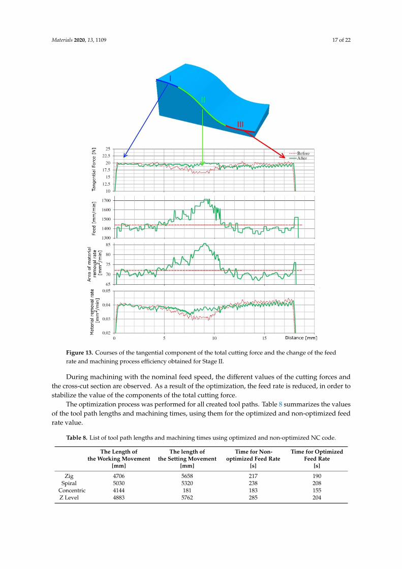
Materials 2020, 13, 1109 17 of 22Materials 2020, 13, x FOR PEER REVIEW 17 of 22
Figure 13. Courses of the tangential component of the total cutting force and the change of the feed
rate and machining process efficiency obtained for Stage II.
The optimization process was performed for all created tool paths. Table 8 summarizes the
values of the tool path lengths and machining times, using them for the optimized and non-optimized
feed rate value.
Table 8. List of tool path lengths and machining times using optimized and non-optimized NC
code.
The Length of the
Working
Movement
The length of the
Setting Movement
Time for Non-
optimized Feed
Rate
Time for
Optimized Feed
Rate
[mm] [mm] [s] [s]
Zig 4706 5658 217 190
Spiral 5030 5320 238 208
Concentric 4144 181 183 155
Z Level 4883 5762 285 204
Figure 13. Courses of the tangential component of the total cutting force and the change of the feedrate and machining process efficiency obtained for Stage II.
During machining with the nominal feed speed, the different values of the cutting forces andthe cross-cut section are observed. As a result of the optimization, the feed rate is reduced, in order tostabilize the value of the components of the total cutting force.
The optimization process was performed for all created tool paths. Table 8 summarizes the valuesof the tool path lengths and machining times, using them for the optimized and non-optimized feedrate value.
Table 8. List of tool path lengths and machining times using optimized and non-optimized NC code.
The Length ofthe Working Movement
The length ofthe Setting Movement
Time for Non-optimized Feed Rate
Time for OptimizedFeed Rate
[mm] [mm] [s] [s]
Zig 4706 5658 217 190Spiral 5030 5320 238 208
Concentric 4144 181 183 155Z Level 4883 5762 285 204
Materials 2020, 13, 1109 18 of 22
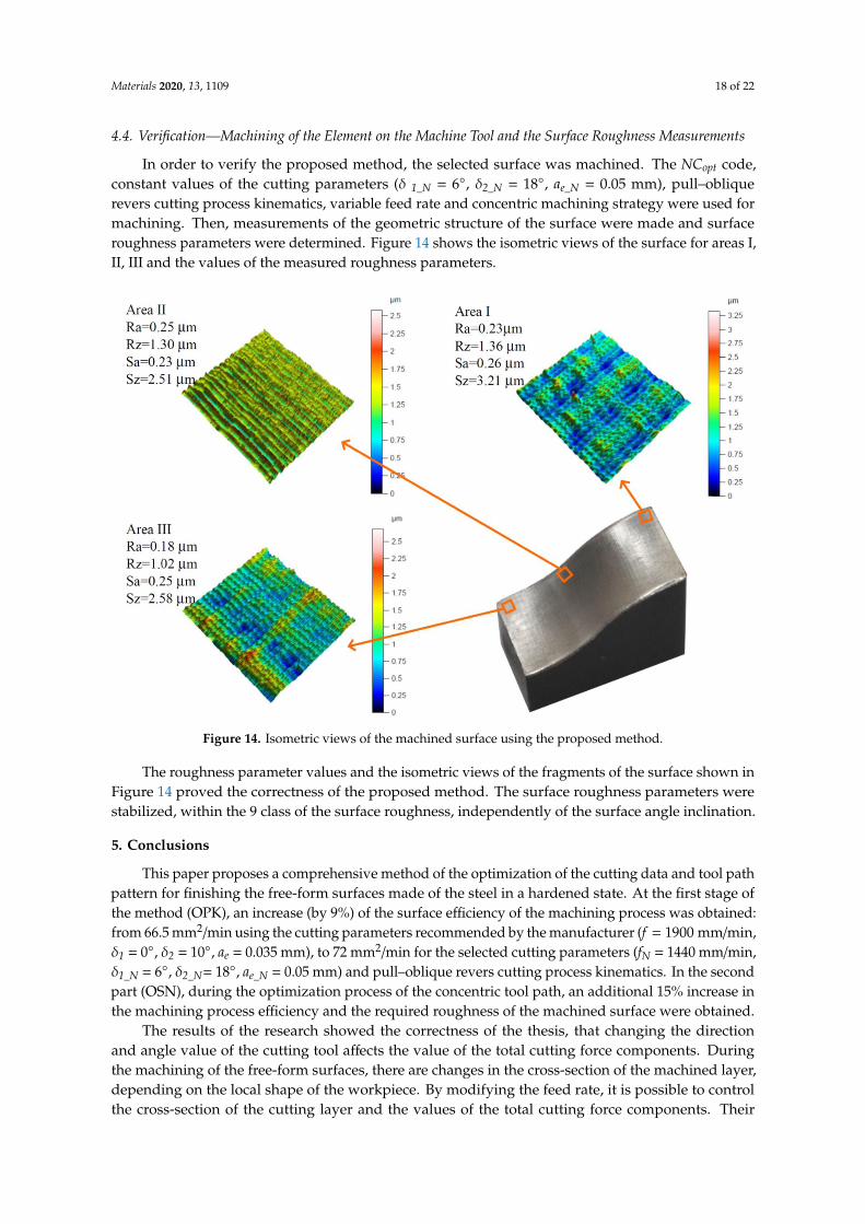
4.4. Verification—Machining of the Element on the Machine Tool and the Surface Roughness Measurements
In order to verify the proposed method, the selected surface was machined. The NCopt code,constant values of the cutting parameters (δ 1_N = 6◦, δ2_N = 18◦, ae_N = 0.05 mm), pull–obliquerevers cutting process kinematics, variable feed rate and concentric machining strategy were used formachining. Then, measurements of the geometric structure of the surface were made and surfaceroughness parameters were determined. Figure 14 shows the isometric views of the surface for areas I,II, III and the values of the measured roughness parameters.
Materials 2020, 13, x FOR PEER REVIEW 18 of 22
4.4. Verification—Machining of the Element on the Machine Tool and the Surface Roughness Measurements
In order to verify the proposed method, the selected surface was machined. The NCopt code,
constant values of the cutting parameters ( 1_N = 6°, 2_N = 18°, ae_N = 0.05 mm), pull–oblique revers
cutting process kinematics, variable feed rate and concentric machining strategy were used for
machining. Then, measurements of the geometric structure of the surface were made and surface
roughness parameters were determined. Figure 14 shows the isometric views of the surface for areas
I, II, III and the values of the measured roughness parameters.
Figure 14. Isometric views of the machined surface using the proposed method.
The roughness parameter values and the isometric views of the fragments of the surface shown
in Figure 14 proved the correctness of the proposed method. The surface roughness parameters were
stabilized, within the 9 class of the surface roughness, independently of the surface angle inclination.
5. Conclusion
This paper proposes a comprehensive method of the optimization of the cutting data and tool
path pattern for finishing the free-form surfaces made of the steel in a hardened state. At the first
stage of the method (OPK), an increase (by 9%) of the surface efficiency of the machining process was
obtained: from 66.5 mm2/min using the cutting parameters recommended by the manufacturer (f =
1900 mm/min, 1 = 0°, 2 = 10°, ae = 0.035 mm ), to 72 mm2/min for the selected cutting parameters (fN
= 1440 mm/min, 1_N = 6°, 2_N = 18°, ae_N = 0.05 mm) and pull–oblique revers cutting process kinematics.
In the second part (OSN), during the optimization process of the concentric tool path, an additional
15% increase in the machining process efficiency and the required roughness of the machined surface
were obtained.
The results of the research showed the correctness of the thesis, that changing the direction and
angle value of the cutting tool affects the value of the total cutting force components. During the
machining of the free-form surfaces, there are changes in the cross-section of the machined layer,
depending on the local shape of the workpiece. By modifying the feed rate, it is possible to control
the cross-section of the cutting layer and the values of the total cutting force components. Their
Figure 14. Isometric views of the machined surface using the proposed method.
The roughness parameter values and the isometric views of the fragments of the surface shown inFigure 14 proved the correctness of the proposed method. The surface roughness parameters werestabilized, within the 9 class of the surface roughness, independently of the surface angle inclination.
5. Conclusions
This paper proposes a comprehensive method of the optimization of the cutting data and tool pathpattern for finishing the free-form surfaces made of the steel in a hardened state. At the first stage ofthe method (OPK), an increase (by 9%) of the surface efficiency of the machining process was obtained:from 66.5 mm2/min using the cutting parameters recommended by the manufacturer (f = 1900 mm/min,δ1 = 0◦, δ2 = 10◦, ae = 0.035 mm), to 72 mm2/min for the selected cutting parameters (fN = 1440 mm/min,δ1_N = 6◦, δ2_N= 18◦, ae_N = 0.05 mm) and pull–oblique revers cutting process kinematics. In the secondpart (OSN), during the optimization process of the concentric tool path, an additional 15% increase inthe machining process efficiency and the required roughness of the machined surface were obtained.
The results of the research showed the correctness of the thesis, that changing the directionand angle value of the cutting tool affects the value of the total cutting force components. Duringthe machining of the free-form surfaces, there are changes in the cross-section of the machined layer,depending on the local shape of the workpiece. By modifying the feed rate, it is possible to controlthe cross-section of the cutting layer and the values of the total cutting force components. Their

Materials 2020, 13, 1109 19 of 22
stabilization at the assumed level aligns the analyzed surface roughness parameters, which positivelyaffects the quality of the machined surface. The method and calculations proposed in the manuscriptwere verified by creating a surface characterized by the assumed surface roughness, as described inSection 4.4.
During the research, the following conclusions were also noticed:
• The significant, non-linear influence of the analyzed inclination angles of the cutting tool andcutting process kinematics on the machined surface roughness is observed.
• Increasing cutting force results in increased load and bending of the cutting tool, which causesdeterioration of the surface roughness.
• The radial depth of cut ae has the greatest impact on the surface roughness parameters. It showsthat the influence of the geometric representation of the cutting tool shape is dominant overthe physical phenomena occurring in the cutting zone.
The method proposed in the work assumes that during machining there is no wear of the tool,which has an impact on the surface roughness. During the tests, no significant tool wear was observed,but when machining larger surfaces, the model should consider the effect of cutting edge wear onsurface roughness.
Author Contributions: Conceptualization, A.M. and W.Z.; Methodology, A.M.; Validation A.M. and W.Z.; FormalAnalysis, A.M.; Investigation, A.M.; Resources, W.Z.; Data Curation, A.M. and W.Z.; Writing—Original DraftPreparation, A.M.; Writing—Review and Editing, W.Z.; Visualization, A.M. and W.Z.; Supervision, W.Z.; ProjectAdministration, W.Z. All authors have read and agreed to the published version of the manuscript.
Funding: This research received no external funding.
Conflicts of Interest: The authors declare no conflict of interest.
Nomenclature
f, fNFeed speed, Nominal value of feed speed enabling the milling of a flat surface withassumed surface roughness
fz Feed per toothap Axial depth of cut
ae, ae_NRadial depth of cut, Nominal value of radial depth of cut enabling the milling ofa flat surface with assumed surface roughness
δ1, δ1_NTool inclination angle in the feed direction (lead angle), Nominal lead angleenabling the milling of a flat surface with assumed surface roughness
δ2, δ2_NTool inclination angle perpendicular to the feed direction (tilt angle), Nominal tiltangle enabling the milling of a flat surface with assumed surface roughness
vc Cutting speedn Spindle SpeedR Radius of the spherical part of the toolAt Machined cross-sectional areaβ Cutting edge engagement angleγ Surface inclination angle
Ra, RamaxArithmetical mean deviation of the assessed profile, Maximum value of Raparameters used as the limitations of the process optimization
Rz, RzmaxAverage distance between the highest peak and lowest valley, Maximum value ofRz parameters used as the limitations of the process optimization
Sa Average Roughness evaluated over the 3D area
SzSum of the largest peak height value and the largest pit depth value evaluated overthe 3D area
Hc Cusp height

Materials 2020, 13, 1109 20 of 22
Qf, Qf_ maxCutting efficiency, Maximum cutting efficiency obtained while milling withnominal cutting data
NC, NCopt NC code, Optimized NC code
Ft, Ft_N, Ft_maxTangential force component (tangential to the machined surface), Nominal value ofFt, Maximum value of Ft used as the limitations of the process optimization
Ff Friction force (component of the cutting force, tangential to the rake face)Fn Normal force (component of the cutting force, normal to the rake face)σf Frictional pressures on the rake faceσn Normal pressures on the rake faceh Average uncut chip thicknessα Rake angle of the toolS Contact surface of chip with the rake face of the toolt, tmin Time, Time of machining with NCopt code
Appendix A
Table A1. Geometry of the milling tool.
Materials 2020, 13, x FOR PEER REVIEW 19 of 22
stabilization at the assumed level aligns the analyzed surface roughness parameters, which positively
affects the quality of the machined surface. The method and calculations proposed in the manuscript
were verified by creating a surface characterized by the assumed surface roughness, as described in
Section 4.4.
During the research, the following conclusions were also noticed:
• The significant, non-linear influence of the analyzed inclination angles of the cutting tool and
cutting process kinematics on the machined surface roughness is observed.
Increasing cutting force results in increased load and bending of the cutting tool, which
causes deterioration of the surface roughness.
The radial depth of cut ae has the greatest impact on the surface roughness parameters. It
shows that the influence of the geometric representation of the cutting tool shape is dominant
over the physical phenomena occurring in the cutting zone.
The method proposed in the work assumes that during machining there is no wear of the tool,
which has an impact on the surface roughness. During the tests, no significant tool wear was
observed, but when machining larger surfaces, the model should consider the effect of cutting edge
wear on surface roughness.
Author Contributions: Conceptualization, A.M. and W.Z.; Methodology, A.M.; Validation A.M. and W.Z.;
Formal Analysis, A.M.; Investigation, A.M.; Resources, W.Z.; Data Curation, A.M. and W.Z.; Writing—Original
Draft Preparation, A.M.; Writing—Review and Editing, W.Z.; Visualization, A.M. and W.Z.; Supervision, W.Z.;
Project Administration, W.Z. All authors have read and agreed to the published version of the manuscript.
Funding: This research received no external funding
Conflicts of Interest: The authors declare no conflict of interest.
Appendix A
Table A1. Geometry of the milling tool.
L1
[mm]
D1
[mm]
ap
[mm]
L3
[mm]
D5
[mm]
B2
[o]
L1
[mm]
D4
[mm]
z
[-]
1 2 1.5 5 1.9 7.3 52 4 2
Appendix B
L1[mm]
D1[mm]
ap[mm]
L3[mm]
D5[mm]
B2[◦]
L1[mm]
D4[mm]
z[-]
1 2 1.5 5 1.9 7.3 52 4 2
Appendix B
Table A2. Average values of the parameters Ra and Rz.
Push–obliquePlunge
Push–obliqueRevers
Pull–obliqueRevers
Pull–obliquePlunge
Lp. ae[mm]
δ1[◦]
δ2[◦]
f[mm/min]
Ra[µm]
Rz[µm]
Ra[µm]
Rz[µm]
Ra[µm]
Rz[µm]
Ra[µm]
Rz[µm]
1 0.1 0 0 720 0.30 2.38 0.36 2.75 0.38 2.72 0.47 2.882 0.1 6 6 960 1.03 4.79 0.50 2.96 0.48 2.57 0.41 2.293 0.1 12 12 1440 0.30 2.01 0.38 2.75 0.33 1.93 0.33 1.784 0.1 18 18 1920 0.40 2.41 0.41 2.91 0.34 2.40 0.51 3.115 0.075 0 6 1440 1.07 5.10 0.95 4.98 0.80 4.05 0.86 4.386 0.075 6 0 1920 0.68 3.54 0.66 3.42 0.68 3.09 0.58 2.907 0.075 12 18 720 0.18 1.21 0.28 2.73 0.24 1.75 0.24 1.538 0.075 18 12 960 0.21 1.39 0.30 2.35 0.22 1.38 0.31 2.809 0.05 0 12 1920 0.42 2.57 0.43 2.70 0.43 2.91 0.35 2.23
10 0.05 6 18 1440 0.30 1.75 0.19 1.57 0.22 1.39 0.20 1.4211 0.05 12 0 960 0.27 1.77 0.27 1.65 0.31 2.91 0.16 1.1412 0.05 18 6 720 0.19 1.28 0.24 1.73 0.18 1.51 0.22 2.3713 0.025 0 18 960 0.20 1.46 0.23 1.66 0.29 1.97 0.17 1.1414 0.025 6 12 720 0.17 1.28 0.18 1.26 0.16 1.24 0.20 1.3315 0.025 12 6 1920 0.21 1.51 0.33 2.54 0.19 1.36 0.23 1.6116 0.025 18 0 1440 0.27 1.74 0.27 1.74 0.17 1.12 0.17 1.12

Materials 2020, 13, 1109 21 of 22
References
1. Devries, R.C. Cubic Boron Nitride: Handbook of Properties; GE Tech. Rep. No 72-CRD 178; General ElectricCorporate Research and Development Schenectady: New York, NY, USA, 1972.
2. Fujisaki, K.; Yokota, H.; Furushiro, N.; Yamagata, Y.; Taniguchi, T.; Himeno, R.; Makinouchi, A.; Higuchi, T.Development of ultra-fine-grain binderless cBN tool for precision cutting of ferrous materials. J. Mater.Process. Technol. 2009, 209, 5646–5652. [CrossRef]
3. Kuzman, K.; Nardin, B. Determination of manufacturing technologies in mould manufacturing. J. Mater.Process. Technol. 2004, 157–158, 573–577. [CrossRef]
4. Vila, C.; Siller, H.R.; Rodriguez, C.A.; Bruscas, G.M.; Serrano, J. Economical and technological study ofsurface grinding versus face milling in hardened AISI D3 steel machining operations. Int. J. Prod. Econ. 2012,138, 273–283. [CrossRef]
5. Soshi, M.; Fonda, P.; Kashihara, M.; Yonetani, H.; Yamazaki, K. A study on cubic boron nitride (CBN) millingof hardened cast iron for productive and quality manufacturing of machine tool structural components.Int. J. Adv. Manuf. Technol. 2013, 65, 1485–1491. [CrossRef]
6. Alam, M.R.; Lee, K.S.; Rahman, M.; Sankaran, K.S. Decision algorithm for selection of high-speed machining,EDM or a combination for the manufacture of injection moulds. Int. J. Prod. Res. 2002, 40, 845–872. [CrossRef]
7. Matras, A.; Zebala, W.; Kowalczyk, R. Precision milling of hardened steel with CBN tools. Key Eng. Mater.2014, 581, 182–187. [CrossRef]
8. Okada, M.; Hosokawa, A.; Tanaka, R.; Ueda, T. Cutting performance of PVD-coated carbide and CBN toolsin hardmilling. Int. J. Mach. Tools Manuf. 2011, 51, 127–132. [CrossRef]
9. Aslan, E. Experimental investigation of cutting tool performance in high speed cutting of hardened X210Cr12 cold-work tool steel (62 HRC). Mater. Des. 2005, 26, 21–27. [CrossRef]
10. Wojciechowski, S.; Maruda, R.W.; Barrans, S.; Nieslony, P.; Krolczyk, G.M. Optimisation of machiningparameters during ball end milling of hardened steel with various surface inclinations. Measurement 2017,111, 18–28. [CrossRef]
11. Klocke, F.; Brinksmeier, E.; Weinert, K. Capability Profile of Hard Cutting and Grinding Processes. CIRP Ann.2005, 54, 22–45. [CrossRef]
12. Navas, V.G.; Ferreres, I.; Marañón, J.A.; Garcia-Rosales, C.; Sevillano, J.G. Electro-discharge machining (EDM)versus hard turning and grinding—Comparison of residual stresses and surface integrity generated in AISIO1 tool steel. J. Mater. Process. Technol. 2008, 195, 186–194. [CrossRef]
13. Jin, M.; Goto, I.; Watanabe, T.; Kurosawa, J.; Murakawa, M. Development of cBN ball-nosed end mill withnewly designed cutting edge. J. Mater. Process. Technol. 2007, 192–193, 48–54. [CrossRef]
14. Beno, J.; Manková, I.; Ižol, P.; Vrabel’, M. An approach to the evaluation of multivariate data during ball endmilling free-form surface fragments. Measurement 2016, 84, 7–20. [CrossRef]
15. Zebala, W.; Plaza, M. Comparative study of 3- and 5-axis CNC centers for free-form machining ofdifficult-to-cut material. Int. J. Prod. Econ. 2014, 158, 345–358. [CrossRef]
16. Durakbasa, M.N.; Akdogan, A.; Vanli, A.S.; Bulutsuz, A.G. Optimization of end milling parameters anddetermination of the effects of edge profile for high surface quality of AISI H13 steel by using precise andfast measurements. Measurement 2015, 68, 92–99. [CrossRef]
17. Chen, X.; Zhao, J.; Dong, Y.; Han, S.; Li, A.; Wang, D. Effects of inclination angles on geometrical features ofmachined surface in five-axis milling. Int. J. Adv. Manuf. Technol. 2013, 65, 1721–1733. [CrossRef]
18. Gao, P.; Wang, X.; Liang, Z.; Zhang, S.; Zhou, T.; Yan, P.; Jiao, L. Effects of machining inclination angles onmicrogroove quality in micro ball end milling of Ti-6Al-4V. Int. J. Adv. Manuf. Technol. 2017, 92, 2725–2734.[CrossRef]
19. Bouzakis, K.-D.; Aichouh, P.; Efstathiou, K. Determination of the chip geometry, cutting force and roughnessin free form surfaces finishing milling, with ball end tools. Int. J. Mach. Tools Manuf. 2003, 43, 499–514.[CrossRef]
20. Ikua, B.W.; Tanaka, H.; Obata, F.; Sakamoto, S.; Kishi, T.; Ishii, T. Prediction of cutting forces and machiningerror in ball end milling of curved surfaces -II experimental verification. Precis. Eng. 2002, 26, 69–82.[CrossRef]

Materials 2020, 13, 1109 22 of 22
21. Scandiffio, I.; Diniz, A.E.; de Souza, A.F. Evaluating surface roughness, tool life, and machining force whenmilling free-form shapes on hardened AISI D6 steel. Int. J. Adv. Manuf. Technol. 2016, 82, 2075–2086.[CrossRef]
22. Ozturk, E.; Tunc, L.T.; Budak, E. Investigation of lead and tilt angle effects in 5-axis ball-end milling processes.Int. J. Mach. Tools Manuf. 2009, 49, 1053–1062. [CrossRef]
23. Yao, C.; Tan, L.; Yang, P.; Zhang, D. Effects of tool orientation and surface curvature on surface integrity inball end milling of TC17. Int. J. Adv. Manuf. Technol. 2018, 94, 1699–1710. [CrossRef]
24. Saffar, R.J.; Razfar, M.R.; Zarei, O.; Ghassemieh, E. Simulation of three-dimension cutting force and tooldeflection in the end milling operation based on finite element method. Simul. Model. Pract. Theory 2008, 16,1677–1688. [CrossRef]
25. De Lacalle, L.N.L.; Lamikiz, A.; Sánchez, J.A.; Arana, J.L. Improving the surface finish in high speed millingof stamping dies. J. Mater. Process. Technol. 2002, 123, 292–302. [CrossRef]
26. Salgado, M.A.; de Lacalle, L.N.L.; Lamikiz, A.; Muñoa, J.; Sánchez, J.A. Evaluation of the stiffness chain onthe deflection of end-mills under cutting forces. Int. J. Mach. Tools Manuf. 2005, 45, 727–739. [CrossRef]
27. Scandiffio, I.; Diniz, A.E.; de Souza, A.F. The influence of tool-surface contact on tool life and surfaceroughness when milling free-form geometries in hardened steel. Int. J. Adv. Manuf. Technol. 2017, 92,615–626. [CrossRef]
28. De Souza, A.F.; Berkenbrock, E.; Diniz, A.E.; Rodrigues, A.R. Influences of the tool path strategy onthe machining force when milling free form geometries with a ball-end cutting tool. J. Braz. Soc. Mech. Sci.Eng. 2015, 37, 675–687. [CrossRef]
29. Wojciechowski, S. The estimation of cutting forces and specific force coefficients during finishing ball endmilling of inclined surfaces. Int. J. Mach. Tools Manuf. 2015, 89, 110–123. [CrossRef]
30. Taguchi, G. Introduction to Quality Engineering: Designing Quality into Products and Processes; Asian ProductivityOrganization: Tokyo, Japan, 1986.
31. Niesłony, P.; Grzesik, W.; Jarosz, K.; Laskowski, P. FEM-based optimization of machining operations ofaerospace parts made of Inconel 718 superalloy. Procedia CIRP 2018, 77, 570–573. [CrossRef]
32. Li, B.; Zhang, S.; Zhang, Q.; Chen, J.; Zhang, J. Modelling of phase transformations induced bythermo-mechanical loads considering stress-strain effects in hard milling of AISI H13 steel. Int. J. Mech. Sci.2018, 149, 241–253. [CrossRef]
33. Third Wave Systems Inc. AdvantEdge and Production Module User’s Manual; Third Wave Systems Inc.:Minneapolis, MN, USA, 2016.
© 2020 by the authors. Licensee MDPI, Basel, Switzerland. This article is an open accessarticle distributed under the terms and conditions of the Creative Commons Attribution(CC BY) license (http://creativecommons.org/licenses/by/4.0/).
Copyright © 2022 FDOKUMEN