Laser - Cutting technology
264
0 - 1 Cutting technology ST_Laser_V20_en.fm © Bystronic Laser AG, 2007 Laser Cutting technology Issued on: 01.2007
-
Upload
khangminh22 -
Category
Documents
-
view
0 -
download
0
Transcript of Laser - Cutting technology

LaserCutting technology
Issued on: 01.2007
0 - 1Cutting technologyST_Laser_V20_en.fm
© Bystronic Laser AG, 2007

Laser
0 - 2 Cutting technologyST_Laser_V20_en.fm
© Bystronic Laser AG, 2007

Laser
Product identification
This cutting technology applies to the following laser cutting systems:
Document identification
Please specify the document identification and issue date when reorder-ing.
Purpose of this document
This cutting technology forms part of the complete set of documentation.It provides information on the fundamentals of cutting with laser cuttingmachines.
Other documents
The complete set of documentation contains the following documents:
Operating instructions
Installation Guide
Cutting technology
Spare parts catalog
Diagrams
Supplier documentation
Machine documentation
Machine logbook
Byspeed
Bystar
Byspint
Cutting technology: ST_Laser_V20_en.fm
0 - 3Cutting technologyST_Laser_V20_en.fm
© Bystronic Laser AG, 2007

Laser
Target group
This document is intended for the owner of the machine and for program-ming and operating personnel.
Storage
This document must always be freely accessible to the specified targetgroup.
Copyright
Dissemination or duplication of this document, or exploitation or commu-nication of its content without the express permission of the copyrightholder is prohibited. Contravention will result in damages. All rights re-served.
0 - 4 Cutting technologyST_Laser_V20_en.fm
© Bystronic Laser AG, 2007

Laser
ArgentinaBEHRENDT MAQUINARIAS S.A.Lima 355 - Piso 8AR-1073 Buenos Aires
Tel.: +54 11 5031 5312Fax: +54 11 5031 5301Email: [email protected]
AustraliaLMC LASER SERVICE PTY. LTDFactory 21 Frias Road, MoorabbinAU-3198 Victoria
Tel.: +61 3 9555 5525Fax: +61 3 9555 2970Email: [email protected]
AustriaBYSTRONIC AUSTRIA GmbHWienerstrasse 131AT-4020 Linz
Tel.: +43 732 341 377 0Fax: +43 732 341 377 11Email: [email protected]
BrazilBYSTRONIC DO BRASIL Ltda.Rua Arapongas, 285BR-83040 200 São CristóvãoSão José dos Pinhais - Paraná
Tel.: +55 41 3398 2000Fax: +55 41 3398 1789Email: [email protected]
ChinaBYSTRONIC CO., LTDRijing Road 88, Level 1 Part AWaigaoqiao FTZ PudongCN-200131 Shanghai
Tel.: +86 21 5868 0480Fax: +86 21 5868 0481Email: [email protected]
ChinaBYSTRONIC MACHINERY CO. LTD.Economic Development ZoneNinghe CountyCN-301500 Tianjin, PRC
Tel.: +86 22 6958 9988Fax: +86 22 6958 8168Email: [email protected]
Czech RepublicCANMET s.r.o.Karlova 37CZ-61400 Brno
Tel.: +420 5 4542 4542Fax: +420 5 4542 4543Email: [email protected]
EnglandBYSTRONIC UK LIMITEDMaple ParkLowfields AvenueGB-Leeds LS12 6HH
Tel.: +44 113 222 8112Fax: +44 113 271 9862Email: [email protected]
FranceBYSTRONIC FRANCE SAParc Technipolis3 avenue du canadaF-91940 Les Ulis
Tel.: +33 1 6941 9984Fax: +33 1 6941 9951Email: [email protected]
GermanyBYSTRONIC DEUTSCHLAND GmbHMollenbachstrasse 33-35D-71229 Leonberg
Tel.: +49 (0)7152 6090 0 Fax: +49 (0)7152 6090 11Email: [email protected]
GreeceADECA SATechnical and Commercial CompanyAve. Alexandras 56GR-11473 Athens
Tel.: +302 10 822 8503Fax: +302 10 821 6746Email: [email protected]
HungaryAUTOREL Kft.Attila ut 131 / III. 12.HU-1012 Budapest
Tel.: +36 1 212 7270Fax: +36 1 212 7271Email: [email protected]
0 - 5Cutting technologyST_Laser_V20_en.fm
© Bystronic Laser AG, 2007

Laser
IsraelALON Laser Services Ltd.23 Robinzon St.IL-49560 Petach-Tikva
Tel.: +972 3 931 0127Fax: +972 3 931 0128Email: [email protected]
ItalyBYSTRONIC ITALIA SRLVia del Lavoro 30I-20030 Bovisio Masciago / MI
Tel.: +39 0362 59931Fax: +39 0362 5941 35Email: [email protected]
NetherlandsBYSTRONIC BENELUX BVStek 8NL-3371 Hardinxveld-Giessendam
Tel.: +31 (184) 611 020Fax: +31 (184) 617 774Email: [email protected]
North AmericaBYSTRONIC INC.Bystronic North American Headquarters185 Commerce DriveHauppauge, NY 11788
Tel.: +1 631 231 1212Fax: +1 631 231 1040Email: [email protected]
MexicoBystronic Mexico S.A. de C.V.Lago Onega No. 424, Col. GranadaMX-11520 Mexiko, D.F.
Tel: + 52 (0)5 525 815 147Fax: +52 (0)5 525 815 156Email: [email protected]
PolandBYSTRONIC POLSKA Sp. z o.o.Al. Krakowska 38JankiPL-05090 Raszyn
Tel.: + 48 22 331 37 70Fax: + 48 22 331 37 71
Russia / Ukraine and Rest CISBystronic Russia Sales Officec/o United Machinery AG2. Hutorskaja Street, 38 ARU-127287 Moscow
Tel.: +7 (495) 961 21 67Fax: +7 (495) 961 21 68Email: [email protected]
SingaporeBYSTRONIC PTE. LTD.2 Leng Kee Road #03-05Thye Hong CentreSG-159086 Singapore
Tel.: +65 6472 6300Fax: +65 6472 2418Email: [email protected]
SlowakeiCANMET s.r.o.Bôrik 5SK-811 02 Bratislava
Tel.: 00421 245 24 28 96Fax: 00421 245 24 77 50Email: [email protected]
South AfricaFOREST ENGINEERINGP.O.Box 169ZA-1600 Isando
Tel.: +27 11 397 4050Fax: +27 11 397 4210Email: [email protected]
South KoreaBYSTRONIC KOREA, LTD6Fl, Teleron B/DKR-1459-2 Gwanyang-dong, Dongan-gu Anyang-siGeonggi-do
Tel.: +82 314 25 5729Fax: +82 314 25 0057
Spain / PortugalBYSTRONIC IBERICA, S.A.Avenida Tenerife No. 2Edifigo 1 3A Planta Oficina DE-28700 San Sebastian de los Reyes
Tel.: +34 91 654 4496Fax: +34 91 652 4983Email: [email protected]
0 - 6 Cutting technologyST_Laser_V20_en.fm
© Bystronic Laser AG, 2007
Laser
SwedenBYSTRONIC SCANDINAVIA ABÖstra Bangatan 18SE-19560 Arlandastad
Tel.: +46 (0)8 5944 1550Fax: +46 (0)8 5944 1555Email: [email protected]
SwitzerlandBYSTRONIC SALES AGIndustriestrasse 21CH-3362 Niederönz
Tel.: +41 (0)62 956 37 83Fax: +41 (0)62 956 33 81Email: [email protected]
TaiwanCHASER C.D. ENTERPRISE CO. LTD22F, No. 639, Chung Cheng Rd.TW-238 Shuh Lin City - Taipei Hsien
Tel.: +886 22 689 7988Fax: +886 22 689 7986Email: [email protected]
TurkeyLASERPRESS LTD.
KiremitdereDedeoglu Cad. No. 60TR-34805 BeykozIstanbul / Turkiye
Tel.: +90 (0)216 413 7677Fax: +90 (0)216 425 2341Email: [email protected]
Rest of the WorldBYSTRONIC LASER AGIndustriestrasse 21CH-3362 Niederönz
Tel.: +41 (0)62 956 3333Fax: +41 (0)62 956 [email protected]
0 - 7Cutting technologyST_Laser_V20_en.fm
© Bystronic Laser AG, 2007

Laser
0 - 8 Cutting technologyST_Laser_V20_en.fm
© Bystronic Laser AG, 2007

Laser
Table of contents
1 Definitions and ranges
1.1 Definitions. . . . . . . . . . . . . . . . . . . . . . . . . . . . . . . . 1 – 31.1.1 Part area . . . . . . . . . . . . . . . . . . . . . . . . . . . . . . . . 1 – 31.1.2 Parts size . . . . . . . . . . . . . . . . . . . . . . . . . . . . . . . 1 – 5
1.2 Ranges . . . . . . . . . . . . . . . . . . . . . . . . . . . . . . . . . . 1 – 61.2.1 Maximum cuttable sheet thicknesses . . . . . . . . . . . . 1 – 61.2.2 Minimum distance from sheet edge . . . . . . . . . . . . . 1 – 71.2.3 Smallest cuttable bores. . . . . . . . . . . . . . . . . . . . . . 1 – 81.2.4 Joint width / minimum joint width . . . . . . . . . . . . . . 1 – 91.2.5 Parts distance . . . . . . . . . . . . . . . . . . . . . . . . . . . . 1 – 101.2.6 Hole patterns . . . . . . . . . . . . . . . . . . . . . . . . . . . . . 1 – 12
1.3 Achievable precision and quality . . . . . . . . . . . . . . 1 – 131.3.1 Parts precision . . . . . . . . . . . . . . . . . . . . . . . . . . . . 1 – 131.3.2 Quality of the cut edge . . . . . . . . . . . . . . . . . . . . . . 1 – 15
0 - 9Cutting technologyST_Laser_V20_enTOC.fm
© Bystronic Laser AG, 2007

Laser
Table of contents
2 The laser cutting process
2.1 Laser cutting areas . . . . . . . . . . . . . . . . . . . . . . . . . 2 – 32.1.1 Laser fusion cutting . . . . . . . . . . . . . . . . . . . . . . . . 2 – 42.1.2 Plasma cutting . . . . . . . . . . . . . . . . . . . . . . . . . . . . 2 – 52.1.3 Laser gas cutting . . . . . . . . . . . . . . . . . . . . . . . . . . 2 – 62.1.4 Laser sublimation cutting . . . . . . . . . . . . . . . . . . . . 2 – 7
2.2 Cutting process . . . . . . . . . . . . . . . . . . . . . . . . . . . . 2 – 82.2.1 Gas parameters . . . . . . . . . . . . . . . . . . . . . . . . . . . 2 – 92.2.2 Cutting gas consumption. . . . . . . . . . . . . . . . . . . . . 2 – 9
0 - 10 Cutting technologyST_Laser_V20_enTOC.fm
© Bystronic Laser AG, 2007

Laser
Table of contents
3 Design and manufacture
3.1 Factors influencing the manufacturing process . . . 3 – 33.2 Material specification . . . . . . . . . . . . . . . . . . . . . . . 3 – 43.3 Design guidelines . . . . . . . . . . . . . . . . . . . . . . . . . . 3 – 5
3.3.1 Sheet formats . . . . . . . . . . . . . . . . . . . . . . . . . . . . 3 – 53.3.2 Cutting gap width for laser cutting . . . . . . . . . . . . . . 3 – 53.3.3 Orthogonality of the cut face . . . . . . . . . . . . . . . . . . 3 – 63.3.4 Roughness of the cut edges . . . . . . . . . . . . . . . . . . . 3 – 73.3.5 Contour radii . . . . . . . . . . . . . . . . . . . . . . . . . . . . . 3 – 93.3.6 Sheet thickness . . . . . . . . . . . . . . . . . . . . . . . . . . . 3 – 10
3.3.6.1 Select small sheet thicknesses . . . . . . . . . . . . . . . 3 – 103.3.6.2 Select equal sheet thicknesses . . . . . . . . . . . . . . . 3 – 10
3.3.7 Common separating cut . . . . . . . . . . . . . . . . . . . . . 3 – 113.3.8 Hanging hole for the paint shop . . . . . . . . . . . . . . . . 3 – 123.3.9 Edge deformation . . . . . . . . . . . . . . . . . . . . . . . . . . 3 – 123.3.10 Cut-outs . . . . . . . . . . . . . . . . . . . . . . . . . . . . . . . . 3 – 133.3.11 Tongues (bent parts only) . . . . . . . . . . . . . . . . . . . . 3 – 143.3.12 Relief cuts . . . . . . . . . . . . . . . . . . . . . . . . . . . . . . . 3 – 153.3.13 Intermittent limb . . . . . . . . . . . . . . . . . . . . . . . . . . 3 – 163.3.14 Tongue and slot joints. . . . . . . . . . . . . . . . . . . . . . . 3 – 173.3.15 Marking similar parts . . . . . . . . . . . . . . . . . . . . . . . 3 – 18
0 - 11Cutting technologyST_Laser_V20_enTOC.fm
© Bystronic Laser AG, 2007
Laser
Table of contents
4 Programming
4.1 General instructions . . . . . . . . . . . . . . . . . . . . . . . . 4 – 34.2 Technology wizard . . . . . . . . . . . . . . . . . . . . . . . . . 4 – 4
4.2.1 Functionality examples . . . . . . . . . . . . . . . . . . . . . . 4 – 64.2.2 Adaptations . . . . . . . . . . . . . . . . . . . . . . . . . . . . . . 4 – 104.2.3 Special features . . . . . . . . . . . . . . . . . . . . . . . . . . . 4 – 104.2.4 Guidelines for piercings . . . . . . . . . . . . . . . . . . . . . . 4 – 114.2.5 Guidelines for initial cut types . . . . . . . . . . . . . . . . . 4 – 134.2.6 Technology on the contour . . . . . . . . . . . . . . . . . . . 4 – 16
4.3 Piercing and initial cuts . . . . . . . . . . . . . . . . . . . . . 4 – 184.3.1 Outer contour . . . . . . . . . . . . . . . . . . . . . . . . . . . . 4 – 194.3.2 Inner contour (cut-outs) . . . . . . . . . . . . . . . . . . . . . 4 – 20
4.4 Using process macros . . . . . . . . . . . . . . . . . . . . . . . 4 – 214.5 Radii on inner and outer contours . . . . . . . . . . . . . 4 – 224.6 Cutting-time calculation . . . . . . . . . . . . . . . . . . . . . 4 – 23
0 - 12 Cutting technologyST_Laser_V20_enTOC.fm
© Bystronic Laser AG, 2007

Laser
Table of contents
5 Cutting parameters
5.1 General instructions . . . . . . . . . . . . . . . . . . . . . . . . 5 – 35.2 Adapting cutting parameters . . . . . . . . . . . . . . . . . 5 – 6
5.2.1 Reasons for parameter adaptations . . . . . . . . . . . . . 5 – 75.2.2 Requirements for parameter adaptations. . . . . . . . . . 5 – 7
5.3 Optimization of cutting parameters . . . . . . . . . . . . 5 – 85.3.1 Procedure . . . . . . . . . . . . . . . . . . . . . . . . . . . . . . . 5 – 85.3.2 Focal position, cutting . . . . . . . . . . . . . . . . . . . . . . . 5 – 105.3.3 Altering the focal position . . . . . . . . . . . . . . . . . . . . 5 – 115.3.4 Laser power, cutting . . . . . . . . . . . . . . . . . . . . . . . . 5 – 125.3.5 Gas pressure, cutting . . . . . . . . . . . . . . . . . . . . . . . 5 – 135.3.6 Feed rate, cutting . . . . . . . . . . . . . . . . . . . . . . . . . . 5 – 145.3.7 Nozzle clearance height for cutting . . . . . . . . . . . . . . 5 – 15
5.4 Cutting with laser source 5 200 W . . . . . . . . . . . . . 5 – 165.4.1 Focal position and beam diameter . . . . . . . . . . . . . . 5 – 16
5.5 Cutting parameters for different dimensional units 5 – 18
0 - 13Cutting technologyST_Laser_V20_enTOC.fm
© Bystronic Laser AG, 2007

Laser
Table of contents
6 Machining process
6.1 General instructions . . . . . . . . . . . . . . . . . . . . . . . . 6 – 36.2 Various technologies. . . . . . . . . . . . . . . . . . . . . . . . 6 – 46.3 Cutting structural steel . . . . . . . . . . . . . . . . . . . . . . 6 – 5
6.3.1 Machining large sheet thickness in structural steel . . . 6 – 76.3.1.1 piercing . . . . . . . . . . . . . . . . . . . . . . . . . . . . . . . 6 – 76.3.1.2 Cutting . . . . . . . . . . . . . . . . . . . . . . . . . . . . . . . 6 – 76.3.1.3 Large parts / large sheet thickness . . . . . . . . . . . . 6 – 86.3.1.4 Example 1: Cutting in one pass . . . . . . . . . . . . . . 6 – 96.3.1.5 Example 2: Cutting in two passes . . . . . . . . . . . . 6 – 106.3.1.6 Example 3: Residual grid cut as heat separation . . 6 – 126.3.1.7 Unsuitable parts for production . . . . . . . . . . . . . . . 6 – 14
6.3.2 Cutting of structural steel with nitrogen (N2) . . . . . . . 6 – 156.4 Pulsed cutting . . . . . . . . . . . . . . . . . . . . . . . . . . . . . 6 – 16
6.4.1 Pulsed cutting (application examples) . . . . . . . . . . . . 6 – 166.4.2 Pulsed piercing (application examples) . . . . . . . . . . . 6 – 176.4.3 Recommended values . . . . . . . . . . . . . . . . . . . . . . . 6 – 186.4.4 Parameter adaptations for complex contours . . . . . . . 6 – 20
6.4.4.1 Adapting the cutting mode pulse parameters . . . . . 6 – 216.4.4.2 Adapting the piercing mode pulse parameters . . . . 6 – 236.4.4.3 Influencing factors in pulsed mode . . . . . . . . . . . . 6 – 236.4.4.4 Alternatives to pulsed cutting . . . . . . . . . . . . . . . . 6 – 236.4.4.5 Programming for pulsed contours . . . . . . . . . . . . . 6 – 246.4.4.6 Background information . . . . . . . . . . . . . . . . . . . . 6 – 27
6.5 Oxide-free cutting of rust and acid-resistant steel. 6 – 286.5.1 Cutting parameters for rust and acid-resistant steel . . 6 – 296.5.2 Rust and acid-resistant steel with protective film . . . . 6 – 29
6.6 Oxide-free cutting of aluminum alloys . . . . . . . . . . 6 – 316.7 Machining diverse materials . . . . . . . . . . . . . . . . . . 6 – 326.8 Plasma cut. . . . . . . . . . . . . . . . . . . . . . . . . . . . . . . . 6 – 35
6.8.1 Practical applications . . . . . . . . . . . . . . . . . . . . . . . 6 – 366.8.2 Cutting parameters for custom sheets . . . . . . . . . . . 6 – 376.8.3 Plasma initial cut type in rust and acid-resistant steel,
15/20 mm thick . . . . . . . . . . . . . . . . . . . . . . . . . . . 6 – 396.8.3.1 Partial plasma cut for sheet thicknesses up to 2 mm 6 – 40
6.8.4 Time comparison between quality and plasma cut . . . 6 – 41
0 - 14 Cutting technologyST_Laser_V20_enTOC.fm
© Bystronic Laser AG, 2007

Laser
Table of contents
6.9 Engraving . . . . . . . . . . . . . . . . . . . . . . . . . . . . . . . . 6 – 436.9.1 General . . . . . . . . . . . . . . . . . . . . . . . . . . . . . . . . . 6 – 436.9.2 Assessing an engraving. . . . . . . . . . . . . . . . . . . . . . 6 – 45
6.10 Machining with process macros . . . . . . . . . . . . . . . 6 – 466.10.1 Process macro 2 for the initial cut. . . . . . . . . . . . . . . 6 – 486.10.2 Example with process macros . . . . . . . . . . . . . . . . . 6 – 49
6.11 Piercing method . . . . . . . . . . . . . . . . . . . . . . . . . . . 6 – 506.11.1 Conventional, pulsed piercing (without monitoring) . . 6 – 516.11.2 CPP(Controlled Pulsed Piercing) . . . . . . . . . . . . . . . . 6 – 52
6.11.2.1 Sequence for a CPP piercing . . . . . . . . . . . . . . . . . 6 – 546.11.3 Normal CW piercing . . . . . . . . . . . . . . . . . . . . . . . . 6 – 566.11.4 Pre-piercing CW . . . . . . . . . . . . . . . . . . . . . . . . . . . 6 – 566.11.5 Pre-piercing CPP. . . . . . . . . . . . . . . . . . . . . . . . . . . 6 – 58
6.12 Microjoints . . . . . . . . . . . . . . . . . . . . . . . . . . . . . . . 6 – 596.12.1 Set microjoints. . . . . . . . . . . . . . . . . . . . . . . . . . . . 6 – 626.12.2 Microjoint welding . . . . . . . . . . . . . . . . . . . . . . . . . 6 – 636.12.3 Alternatives to microjoints . . . . . . . . . . . . . . . . . . . . 6 – 64
6.13 Machining corners. . . . . . . . . . . . . . . . . . . . . . . . . . 6 – 656.13.1 Machining corners with corner tolerance . . . . . . . . . . 6 – 656.13.2 Pointed corners in thick sheets
(with Dwell time parameter) . . . . . . . . . . . . . . . . . . 6 – 666.14 Support grids . . . . . . . . . . . . . . . . . . . . . . . . . . . . . 6 – 67
6.14.1 Standard support grid . . . . . . . . . . . . . . . . . . . . . . . 6 – 676.14.1.1 Advantages . . . . . . . . . . . . . . . . . . . . . . . . . . . . 6 – 676.14.1.2 Disadvantages . . . . . . . . . . . . . . . . . . . . . . . . . . 6 – 67
6.14.2 Support grid for thin sheets . . . . . . . . . . . . . . . . . . . 6 – 686.14.2.1 Advantages . . . . . . . . . . . . . . . . . . . . . . . . . . . . 6 – 686.14.2.2 Disadvantages . . . . . . . . . . . . . . . . . . . . . . . . . . 6 – 68
6.14.3 Materials for support grids. . . . . . . . . . . . . . . . . . . . 6 – 696.15 Low-staff production. . . . . . . . . . . . . . . . . . . . . . . . 6 – 71
6.15.1 Recommendations . . . . . . . . . . . . . . . . . . . . . . . . . 6 – 71
0 - 15Cutting technologyST_Laser_V20_enTOC.fm
© Bystronic Laser AG, 2007

Laser
Table of contents
7 Materials
7.1 Material properties . . . . . . . . . . . . . . . . . . . . . . . . . 7 – 27.1.1 alloy constituents, . . . . . . . . . . . . . . . . . . . . . . . . . 7 – 27.1.2 microstructure, . . . . . . . . . . . . . . . . . . . . . . . . . . . 7 – 37.1.3 Material surface . . . . . . . . . . . . . . . . . . . . . . . . . . . 7 – 3
7.1.3.1 Positive effects . . . . . . . . . . . . . . . . . . . . . . . . . . 7 – 37.1.3.2 Negative effects . . . . . . . . . . . . . . . . . . . . . . . . . 7 – 37.1.3.3 Oil . . . . . . . . . . . . . . . . . . . . . . . . . . . . . . . . . . . 7 – 4
7.2 beam reflection, . . . . . . . . . . . . . . . . . . . . . . . . . . . 7 – 57.3 thermal conductivity, . . . . . . . . . . . . . . . . . . . . . . . 7 – 67.4 Heat-affected zone . . . . . . . . . . . . . . . . . . . . . . . . . 7 – 77.5 Stresses . . . . . . . . . . . . . . . . . . . . . . . . . . . . . . . . . 7 – 8
0 - 16 Cutting technologyST_Laser_V20_enTOC.fm
© Bystronic Laser AG, 2007

Laser
Table of contents
8 High-dynamic cutting
8.1 General instructions . . . . . . . . . . . . . . . . . . . . . . . . 8 – 28.1.1 Application. . . . . . . . . . . . . . . . . . . . . . . . . . . . . . . 8 – 28.1.2 Part programming . . . . . . . . . . . . . . . . . . . . . . . . . 8 – 2
8.2 Optimum parts programming . . . . . . . . . . . . . . . . . 8 – 38.2.1 Initial cuts . . . . . . . . . . . . . . . . . . . . . . . . . . . . . . . 8 – 3
8.2.1.1 Machining without initial cuts . . . . . . . . . . . . . . . . 8 – 38.2.1.2 Machining with initial cut . . . . . . . . . . . . . . . . . . . 8 – 38.2.1.3 Initial cut type . . . . . . . . . . . . . . . . . . . . . . . . . . 8 – 48.2.1.4 Initial cut point . . . . . . . . . . . . . . . . . . . . . . . . . . 8 – 5
8.2.2 Direction of rotation and cutting sequence in the part . 8 – 68.2.3 Positioning in Bysoft . . . . . . . . . . . . . . . . . . . . . . . . 8 – 78.2.4 Positioning the machine axes . . . . . . . . . . . . . . . . . . 8 – 88.2.5 Hole patterns . . . . . . . . . . . . . . . . . . . . . . . . . . . . . 8 – 88.2.6 Thin sheet machining using scanning . . . . . . . . . . . . 8 – 9
8.2.6.1 Schematic representation of the machiningsequence . . . . . . . . . . . . . . . . . . . . . . . . . . . . . . 8 – 9
8.2.6.2 Machining characteristics for scanning . . . . . . . . . . 8 – 108.2.6.3 Machining example . . . . . . . . . . . . . . . . . . . . . . . 8 – 11
8.2.7 Erect parts after machining . . . . . . . . . . . . . . . . . . . 8 – 128.2.8 Thin sheet grids . . . . . . . . . . . . . . . . . . . . . . . . . . . 8 – 138.2.9 Part machining sequence. . . . . . . . . . . . . . . . . . . . . 8 – 138.2.10 Warping . . . . . . . . . . . . . . . . . . . . . . . . . . . . . . . . 8 – 148.2.11 Pointed corners in thick sheets with loops . . . . . . . . . 8 – 14
8.3 Cutting parameters . . . . . . . . . . . . . . . . . . . . . . . . . 8 – 158.4 Production. . . . . . . . . . . . . . . . . . . . . . . . . . . . . . . . 8 – 168.5 Quality of the main sheets . . . . . . . . . . . . . . . . . . . 8 – 17
0 - 17Cutting technologyST_Laser_V20_enTOC.fm
© Bystronic Laser AG, 2007

Laser
Table of contents
9 Tube processing
9.1 General instructions . . . . . . . . . . . . . . . . . . . . . . . . 9 – 39.2 Reducing the heat . . . . . . . . . . . . . . . . . . . . . . . . . . 9 – 59.3 Adjustment of cutting parameters . . . . . . . . . . . . . 9 – 69.4 Machining square and rectangular tubes . . . . . . . . 9 – 79.5 Quality of tubes and precision . . . . . . . . . . . . . . . . 9 – 8
0 - 18 Cutting technologyST_Laser_V20_enTOC.fm
© Bystronic Laser AG, 2007

Laser
Table of contents
10 Repositioning machines
10.1 General instructions . . . . . . . . . . . . . . . . . . . . . . . . 10 – 310.2 Creating the cutting plan . . . . . . . . . . . . . . . . . . . . 10 – 410.3 Production. . . . . . . . . . . . . . . . . . . . . . . . . . . . . . . . 10 – 6
0 - 19Cutting technologyST_Laser_V20_enTOC.fm
© Bystronic Laser AG, 2007
Laser
Table of contents
11 Cut evaluation
11.1 General instructions . . . . . . . . . . . . . . . . . . . . . . . . 11 – 311.2 Cutting with oxygen (O2) . . . . . . . . . . . . . . . . . . . . 11 – 4
11.2.1 Structural steel 37-2, 4 mm thick . . . . . . . . . . . . . . 11 – 411.2.2 Structural steel 37-2, 10 mm thick . . . . . . . . . . . . . 11 – 611.2.3 Structural steel, 15 mm thick. . . . . . . . . . . . . . . . . . 11 – 911.2.4 Structural steel RAEX 420 Laser, 20 mm thick . . . . . . 11 – 1011.2.5 Rust and acid-resistant steel 1.4301, 6 mm thick . . . . 11 – 12
11.3 Cutting with nitrogen (N2) . . . . . . . . . . . . . . . . . . . 11 – 1311.3.1 Structural steel, hot galvanized, 2 mm thick . . . . . . . 11 – 1311.3.2 Structural steel 37-2, 6 mm thick . . . . . . . . . . . . . . 11 – 1411.3.3 Rust and acid-resistant steel 1.4301, 6 mm thick . . . . 11 – 1611.3.4 Rust and acid-resistant steel 1.4301, 10 mm thick . . . 11 – 1711.3.5 Rust and acid-resistant steel 1.4301, 20 mm thick . . . 11 – 2111.3.6 Aluminum AlMg3, 3 mm thick . . . . . . . . . . . . . . . . . 11 – 2211.3.7 Aluminum AlMg3, 12 mm thick . . . . . . . . . . . . . . . . 11 – 2411.3.8 Brass, 5 mm thick . . . . . . . . . . . . . . . . . . . . . . . . . 11 – 2611.3.9 Copper, 3 mm thick . . . . . . . . . . . . . . . . . . . . . . . . 11 – 2711.3.10 Titanium, 3 mm thick . . . . . . . . . . . . . . . . . . . . . . . 11 – 27
11.4 Cutting with argon (Ar) . . . . . . . . . . . . . . . . . . . . . 11 – 2811.4.1 Titanium, 3 mm thick . . . . . . . . . . . . . . . . . . . . . . . 11 – 28
11.5 Piercing with oxygen (O2) . . . . . . . . . . . . . . . . . . . 11 – 2911.5.1 Structural steel 37-2, 6 mm thick . . . . . . . . . . . . . . 11 – 29
11.6 Piercing with nitrogen (N2) . . . . . . . . . . . . . . . . . . 11 – 3011.6.1 Rust and acid-resistant steel 1.4301, 2 mm thick . . . . 11 – 3011.6.2 Rust and acid-resistant steel 1.4301, 10 mm thick . . . 11 – 3211.6.3 Aluminum AlMg3, 12 mm thick . . . . . . . . . . . . . . . . 11 – 33
11.7 Quality of cut edges . . . . . . . . . . . . . . . . . . . . . . . . 11 – 34
0 - 20 Cutting technologyST_Laser_V20_enTOC.fm
© Bystronic Laser AG, 2007

Laser
Table of contents
12 Fault finding
12.1 General instructions . . . . . . . . . . . . . . . . . . . . . . . . 12 – 312.2 Parameters . . . . . . . . . . . . . . . . . . . . . . . . . . . . . . . 12 – 412.3 Cutting head . . . . . . . . . . . . . . . . . . . . . . . . . . . . . . 12 – 512.4 Beam guidance system . . . . . . . . . . . . . . . . . . . . . . 12 – 612.5 Laser module . . . . . . . . . . . . . . . . . . . . . . . . . . . . . 12 – 7
0 - 21Cutting technologyST_Laser_V20_enTOC.fm
© Bystronic Laser AG, 2007

Laser
0 - 22 Cutting technologyST_Laser_V20_enTOC.fm
© Bystronic Laser AG, 2007
Laser
Chapter 1
1 Definitions and ranges
This chapter provides important information needed to ensure a safe cut-ting process.
1 - 1Cutting technologyST_Laser_Kap01.fm
© Bystronic Laser AG, 2007

LaserDefinitions and ranges
1 - 2 Cutting technologyST_Laser_Kap01.fm
© Bystronic Laser AG, 2007

Laser Definitions and ranges
1.1 Definitions
1.1.1 Part area
The area of a geometric part is defined on the basis of the following crite-ria:
Fig. 1.1-1 Calculating a part area
Part area A = Area within a closed outer contour. Bores, slots andopenings are subtracted.
Element Dimension Area
1 Square 100 x 100 mm 10 000 mm2
2 bore ∅20 mm -314 mm2
3 Rectangular 110 x 20 mm -314 mm2
4 bore ∅20 mm -2 200 mm2
A Part area 7 172 mm2
= 71.72 cm2
A
1
2
3
4
1 - 3Cutting technologyST_Laser_Kap01.fm
© Bystronic Laser AG, 2007
LaserDefinitions and ranges
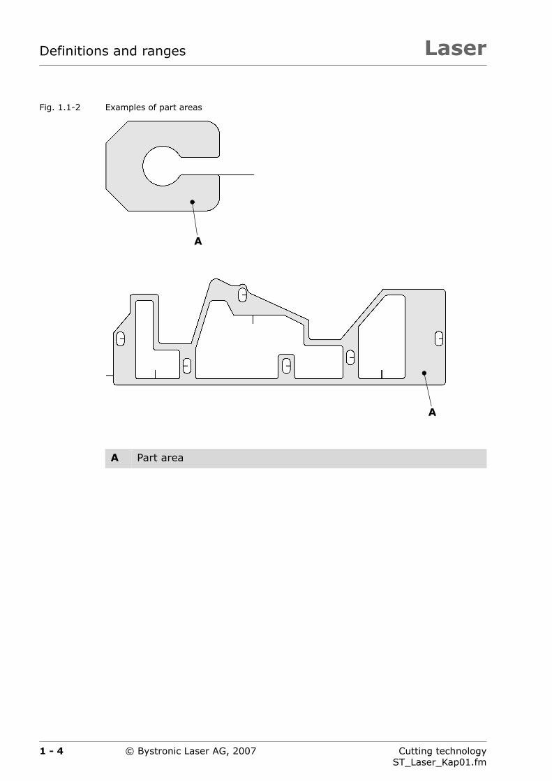
Fig. 1.1-2 Examples of part areas
A Part area
A
A
1 - 4 Cutting technologyST_Laser_Kap01.fm
© Bystronic Laser AG, 2007
Laser Definitions and ranges
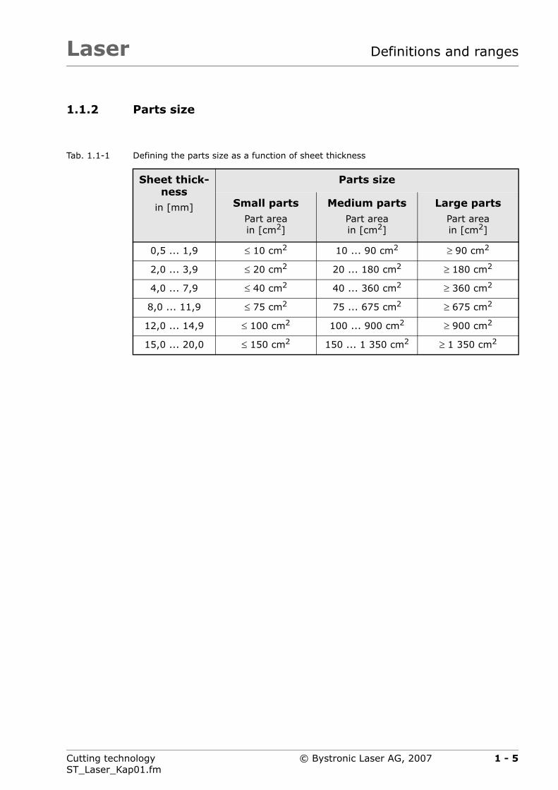
1.1.2 Parts size
Tab. 1.1-1 Defining the parts size as a function of sheet thickness
Sheet thick-ness
in [mm]
Parts size
Small partsPart areain [cm2]
Medium partsPart areain [cm2]
Large partsPart areain [cm2]
0,5 ... 1,9 ≤ 10 cm2 10 ... 90 cm2 ≥ 90 cm2
2,0 ... 3,9 ≤ 20 cm2 20 ... 180 cm2 ≥ 180 cm2
4,0 ... 7,9 ≤ 40 cm2 40 ... 360 cm2 ≥ 360 cm2
8,0 ... 11,9 ≤ 75 cm2 75 ... 675 cm2 ≥ 675 cm2
12,0 ... 14,9 ≤ 100 cm2 100 ... 900 cm2 ≥ 900 cm2
15,0 ... 20,0 ≤ 150 cm2 150 ... 1 350 cm2 ≥ 1 350 cm2
1 - 5Cutting technologyST_Laser_Kap01.fm
© Bystronic Laser AG, 2007
LaserDefinitions and ranges
1.2 Ranges
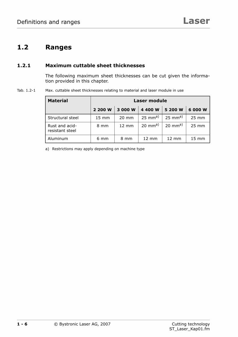
1.2.1 Maximum cuttable sheet thicknesses
The following maximum sheet thicknesses can be cut given the informa-tion provided in this chapter.
Tab. 1.2-1 Max. cuttable sheet thicknesses relating to material and laser module in use
Material Laser module
2 200 W 3 000 W 4 400 W 5 200 W 6 000 W
Structural steel 15 mm 20 mm 25 mma)
a) Restrictions may apply depending on machine type
25 mma) 25 mm
Rust and acid-resistant steel
8 mm 12 mm 20 mma) 20 mma) 25 mm
Aluminum 6 mm 8 mm 12 mm 12 mm 15 mm
1 - 6 Cutting technologyST_Laser_Kap01.fm
© Bystronic Laser AG, 2007

Laser Definitions and ranges
1.2.2 Minimum distance from sheet edge
The minimum distance from the sheet edge is 10 mm for a reliable cuttingprocess.
Fig. 1.2-1 Distance from sheet edge
During high-dynamic cutting1), the main sheet must be clamped. This re-duces the usable surface by 40 mm. See section 8 ›High-dynamic cutting‹
Fig. 1.2-2 Distance from sheet edge during high-dynamic cutting
1) Only available with Byspeed machine type.
10 mm 10 mm
10
mm
10
mm
B
A
A Sheet
B Cutting plan
50 mm 10 mm
10
mm
10
mm
B
A
1 - 7Cutting technologyST_Laser_Kap01.fm
© Bystronic Laser AG, 2007

LaserDefinitions and ranges
1.2.3 Smallest cuttable bores
Small bores are pulsed in relation to the sheet thickness or cut with a pro-cess macro. The Technology wizard carries out the exact assignment ofthe best technology in Bysoft.
Tab. 1.2-2 Smallest cuttable bore
Sheet thickness Smallest cuttable bore
Maximum cuttable sheet thickness ac-cord. to Tab. 1.2-1
1 x sheet thickness
All other sheet thicknesses 0,5 x sheet thickness
Parts quality may suffer or parts may be rejected if hole diame-ters are less than the minimum hole diameters.
1 - 8 Cutting technologyST_Laser_Kap01.fm
© Bystronic Laser AG, 2007
Laser Definitions and ranges
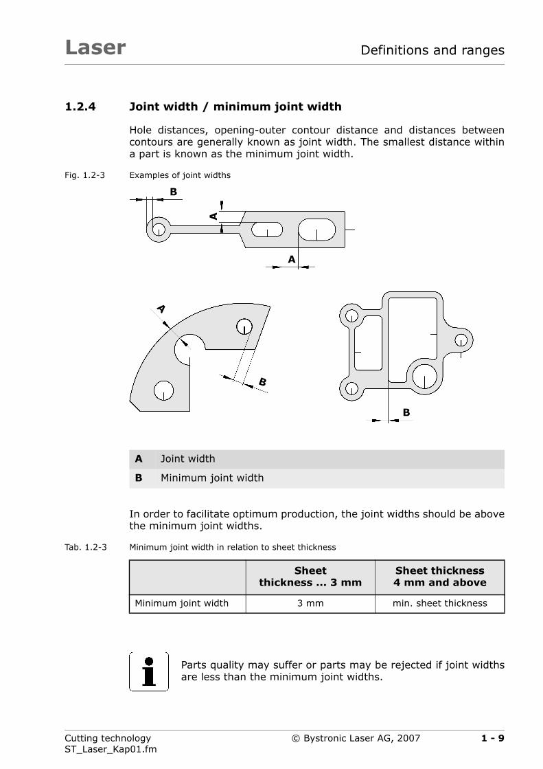
1.2.4 Joint width / minimum joint width
Hole distances, opening-outer contour distance and distances betweencontours are generally known as joint width. The smallest distance withina part is known as the minimum joint width.
Fig. 1.2-3 Examples of joint widths
In order to facilitate optimum production, the joint widths should be abovethe minimum joint widths.
Tab. 1.2-3 Minimum joint width in relation to sheet thickness
A Joint width
B Minimum joint width
A
B
A
B
A
B
Sheet thickness ... 3 mm
Sheet thickness 4 mm and above
Minimum joint width 3 mm min. sheet thickness
Parts quality may suffer or parts may be rejected if joint widthsare less than the minimum joint widths.
1 - 9Cutting technologyST_Laser_Kap01.fm
© Bystronic Laser AG, 2007

LaserDefinitions and ranges
1.2.5 Parts distance
The minimum distance between two parts is known as the parts distance.Initial cuts outside of the contour are integral to the part.
The minimum parts distance for a reliable process is 10 mm (see Tab. 1.2-4). This applies to other parts as well as the sheet edge.
Fig. 1.2-4 Parts distance examples
In order to facilitate optimum production, the parts distance should beabove the minimum parts distance.
A Parts distance in x-direction
B Parts distance in y-direction
B
A
B
A
1 - 10 Cutting technologyST_Laser_Kap01.fm
© Bystronic Laser AG, 2007

Laser Definitions and ranges
Tab. 1.2-4 Minimum parts distance with respect to sheet thickness
Material Cutting gas
Sheet thickness
... 10 mm 10 mm & above
Structural steel Oxygen
O2
min. 10 mm min. sheet thick-ness
Rust and acid-resistant steel
Nitrogen
N2
min. 10 mm min. 10 mm
Aluminum min. 10 mm min. 10 mm
Structural steel min. 10 mm Not possible
Parts quality may be poor or the parts may be rejected if theparts distance is not above the minimum parts distance.
1 - 11Cutting technologyST_Laser_Kap01.fm
© Bystronic Laser AG, 2007

LaserDefinitions and ranges
1.2.6 Hole patterns
Large parts can partially overheat if tightly-spaced hole patterns are cut.The same rules and definitions apply for hole patterns as for the corre-sponding individual part.
Fig. 1.2-5 Example of a hole pattern
1 - 12 Cutting technologyST_Laser_Kap01.fm
© Bystronic Laser AG, 2007

Laser Definitions and ranges
1.3 Achievable precision and quality
1.3.1 Parts precision
The tables below are based on the DIN 2310 Thermal cutting standard,which has been extended for laser cutting.
The given tolerances are empirical values for laser flame cutting and laserfusion cutting.
Tab. 1.3-1 Parts precision
Sheet thickness
in [mm]
Part lengthin [mm]
0 ... 10 10 ... 100 100 ... 300 300 ... 1 000
0,5 ... 2,9 ±0.10 mm ±0.10 mm ±0.20 mm ±0.25 mm
3 ... 5,9 ±0.20 mm ±0.20 mm ±0.20 mm ±0.25 mm
6 ... 9,9 ±0.20 mm ±0.20 mm ±0.20 mm ±0.30 mm
10 ... 14,9 ±0.25 mm ±0.25 mm ±0.30 mm ±0.30 mm
15 ... 19,9 ±0.30 mm ±0.30 mm ±0.30 mm ±0.30 mm
20 ... 25 ±0.35 mm ±0.35 mm ±0.35 mm ±0.40 mm
Sheet thickness
in [mm]
Part lengthin [mm]
1 000 ... 2 000 2 000 ... 3 000 3 000 ... 4 000
0,5 ... 2,9 ±0.30 mm ±0.40 mm ±0.50 mm
3 ... 5,9 ±0.40 mm ±0.50 mm ±0.60 mm
6 ... 9,9 ±0.40 mm ±0.50 mm ±0.60 mm
10 ... 14,9 ±0.40 mm ±0.60 mm ±0.80 mm
15 ... 19,9 ±0.50 mm ±0.60 mm ±0.80 mm
20 ... 25 ±0.60 mm ±0.70 mm ±1.00 mm
1 - 13Cutting technologyST_Laser_Kap01.fm
© Bystronic Laser AG, 2007

LaserDefinitions and ranges
The following conditions must be met in order to achieve the tolerances inTab. 1.3-1 for all parts:
Optimized cutting results, in particular tool compensation (generally thedefault parameters)
When measuring parts, the evenness must be identical to the cuttingsituation.
The internal stress of the main sheet is not taken into consideration inthe tables. Warping has a negative effect on the results.
The roughness must not influence the measurement.
Measurements may not be performed at the starting point of the con-tour.
The relevant measurements may only be performed on parts with bareedges.
Good system condition including all optical elements
Measurement and analysis procedure to VDI/DGQ 3441
Strong heating of the main sheet during cutting has a negative effect onprecision.
The mechanical precision of the laser cutting machines is muchgreater than the precision of the parts (see Product descrip-tion).
1 - 14 Cutting technologyST_Laser_Kap01.fm
© Bystronic Laser AG, 2007

1 - 15 Cutting technologyST_Laser_Kap01.fm
Lase Definitions and ranges
1.3.2
Tab. 1.3-2
Laser module
W 4 400 W 5 200 W 6 000 W
mm 0,5 ... 15 mm 0,5 ... 15 mm 0,5 ... 15 mm
20 ... 25 mm 20 ... 25 mm 20 ... 25 mm
© Bystronic Laser AG, 2007
r
Quality of the cut edge
Structural steel cut with oxygen
Cut edge
2 200 W 3 000
Oxidized cut edge burr-free. The layer of oxide must be removed before subsequent surface treatment (e.g. powder coating, varnishing, etc.).
0,5 ... 10 mm 0,5 ... 15
Oxidized cut edge burr-free. The layer of oxide must be removed before subsequent surface treatment (e.g. powder coating, varnishing, etc.).
The main sheet may overheat when cutting small parts or several cut-outs
12 ... 15 mm 20 mm
1 - 16 Cutting technologyST_Laser_Kap01.fm
Lase Definitions and ranges
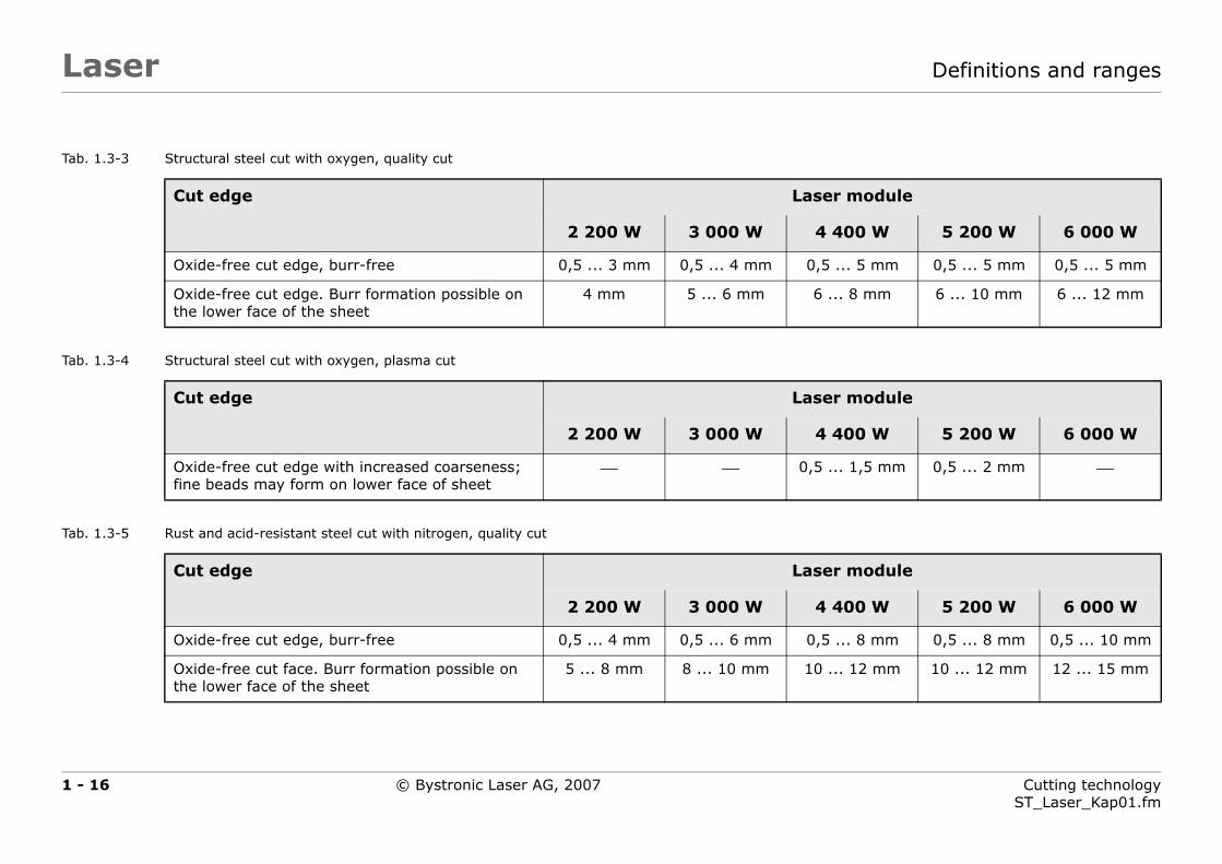
Tab. 1.3-3
Tab. 1.3-4
Tab. 1.3-5
Laser module
W 4 400 W 5 200 W 6 000 W
mm 0,5 ... 5 mm 0,5 ... 5 mm 0,5 ... 5 mm
m 6 ... 8 mm 6 ... 10 mm 6 ... 12 mm
Laser module
W 4 400 W 5 200 W 6 000 W
0,5 ... 1,5 mm 0,5 ... 2 mm ⎯
Laser module
W 4 400 W 5 200 W 6 000 W
mm 0,5 ... 8 mm 0,5 ... 8 mm 0,5 ... 10 mm
m 10 ... 12 mm 10 ... 12 mm 12 ... 15 mm
© Bystronic Laser AG, 2007
r
Structural steel cut with oxygen, quality cut
Structural steel cut with oxygen, plasma cut
Rust and acid-resistant steel cut with nitrogen, quality cut
Cut edge
2 200 W 3 000
Oxide-free cut edge, burr-free 0,5 ... 3 mm 0,5 ... 4
Oxide-free cut edge. Burr formation possible on the lower face of the sheet
4 mm 5 ... 6 m
Cut edge
2 200 W 3 000
Oxide-free cut edge with increased coarseness; fine beads may form on lower face of sheet
⎯ ⎯
Cut edge
2 200 W 3 000
Oxide-free cut edge, burr-free 0,5 ... 4 mm 0,5 ... 6
Oxide-free cut face. Burr formation possible on the lower face of the sheet
5 ... 8 mm 8 ... 10 m

1 - 17 Cutting technologyST_Laser_Kap01.fm
Lase Definitions and ranges
Tab. 1.3-6
Tab. 1.3-7
Laser module
W 4 400 W 5 200 W 6 000 W
0,5 ... 1,5 mm 0,5 ... 2 mm ⎯
15 ... 20 mm 15 ... 20 mm 20 ... 25 mm
Laser module
W 4 400 W 5 200 W 6 000 W
mm 0,5 ... 3 mm 0,5 ... 3 mm 0,5 ... 3 mm
mm 4 ... 12 mm 4 ... 12 mm 4 ... 15 mm
© Bystronic Laser AG, 2007
r
Rust and acid-resistant steel cut with nitrogen, plasma cut
Aluminum cut with nitrogen
Cut edge
2 200 W 3 000
Oxide-free cut edge with increased coarseness; fine beads may form on lower face of sheet
⎯ ⎯
Oxide-free cut edge with increased coarseness; beads may form on lower face of sheet
⎯ ⎯
Cut edge
2 200 W 3 000
Oxide-free cut edge, burr-free 0,5 ... 2.5 mm 0,5 ... 3
Oxide-free cut edge. Burr formation possible on the lower face of the sheet
3 ... 6 mm 4 ... 8

LaserDefinitions and ranges
1 - 18 Cutting technologyST_Laser_Kap01.fm
© Bystronic Laser AG, 2007
Laser
Chapter 2
2 The laser cutting process
This chapter provides information about the cutting procedures that canbe used with the laser cutting machine.
2 - 1Cutting technologyST_Laser_Kap02.fm
© Bystronic Laser AG, 2007

LaserThe laser cutting process
2 - 2 Cutting technologyST_Laser_Kap02.fm
© Bystronic Laser AG, 2007
Laser The laser cutting process
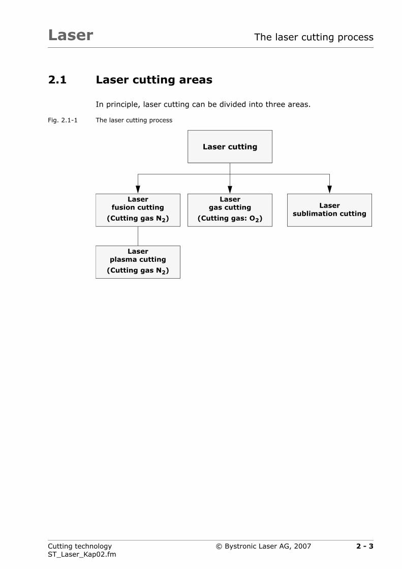
2.1 Laser cutting areas
In principle, laser cutting can be divided into three areas.
Fig. 2.1-1 The laser cutting process
Laserplasma cutting
(Cutting gas N2)
Laserfusion cutting
(Cutting gas N2)
Lasergas cutting
(Cutting gas: O2)
Lasersublimation cutting
Laser cutting
2 - 3Cutting technologyST_Laser_Kap02.fm
© Bystronic Laser AG, 2007
LaserThe laser cutting process
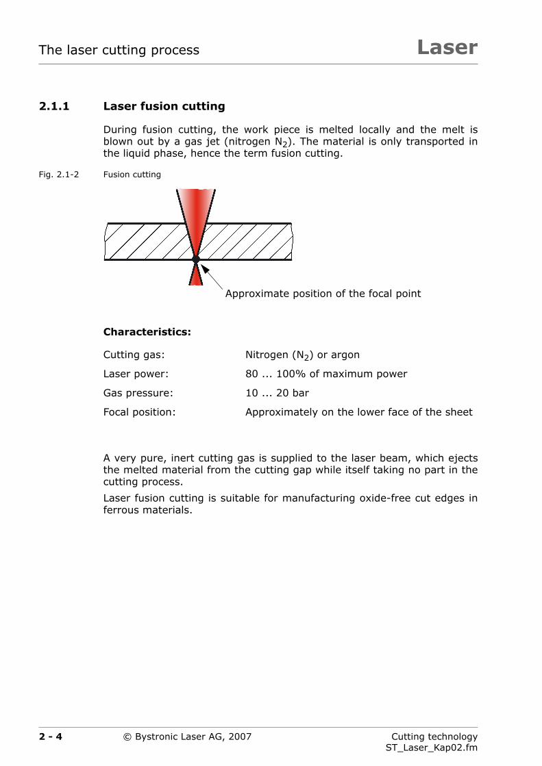
2.1.1 Laser fusion cutting
During fusion cutting, the work piece is melted locally and the melt isblown out by a gas jet (nitrogen N2). The material is only transported inthe liquid phase, hence the term fusion cutting.
Fig. 2.1-2 Fusion cutting
Characteristics:
A very pure, inert cutting gas is supplied to the laser beam, which ejectsthe melted material from the cutting gap while itself taking no part in thecutting process.
Laser fusion cutting is suitable for manufacturing oxide-free cut edges inferrous materials.
Cutting gas: Nitrogen (N2) or argon
Laser power: 80 ... 100% of maximum power
Gas pressure: 10 ... 20 bar
Focal position: Approximately on the lower face of the sheet
Approximate position of the focal point
2 - 4 Cutting technologyST_Laser_Kap02.fm
© Bystronic Laser AG, 2007

Laser The laser cutting process
2.1.2 Plasma cutting
Plasma cutting falls into the laser fusion cutting category. By altering thecutting parameters, a bright light (similar to an arc) can be generated.
Using this method it is possible to cut faster up to a sheet thickness of1.5 mm and to cut sheet thicknesses which would not otherwise be possi-ble (rust- & acid-resistant steel, 15 ... 20 mm thick).
Fig. 2.1-3 Plasma cutting
Characteristics:
Bright light in the cutting gap during cutting.
An oxide-free cut edge is generated using plasma cutting.
Rust and acid-resistantsteel, thickness 15 ... 20 mm
Sheet thickness up to 1.5 mm
Cutting gas: Nitrogen N2
Feed rate: Up to 40% faster than for normal laser fusioncutting
Laser power: Mostly maximum power
Cut quality: Increased roughness (plasma cut)
Cut monitoring with Cut Control not possible.
Approximate position of the focal point
2 - 5Cutting technologyST_Laser_Kap02.fm
© Bystronic Laser AG, 2007
LaserThe laser cutting process
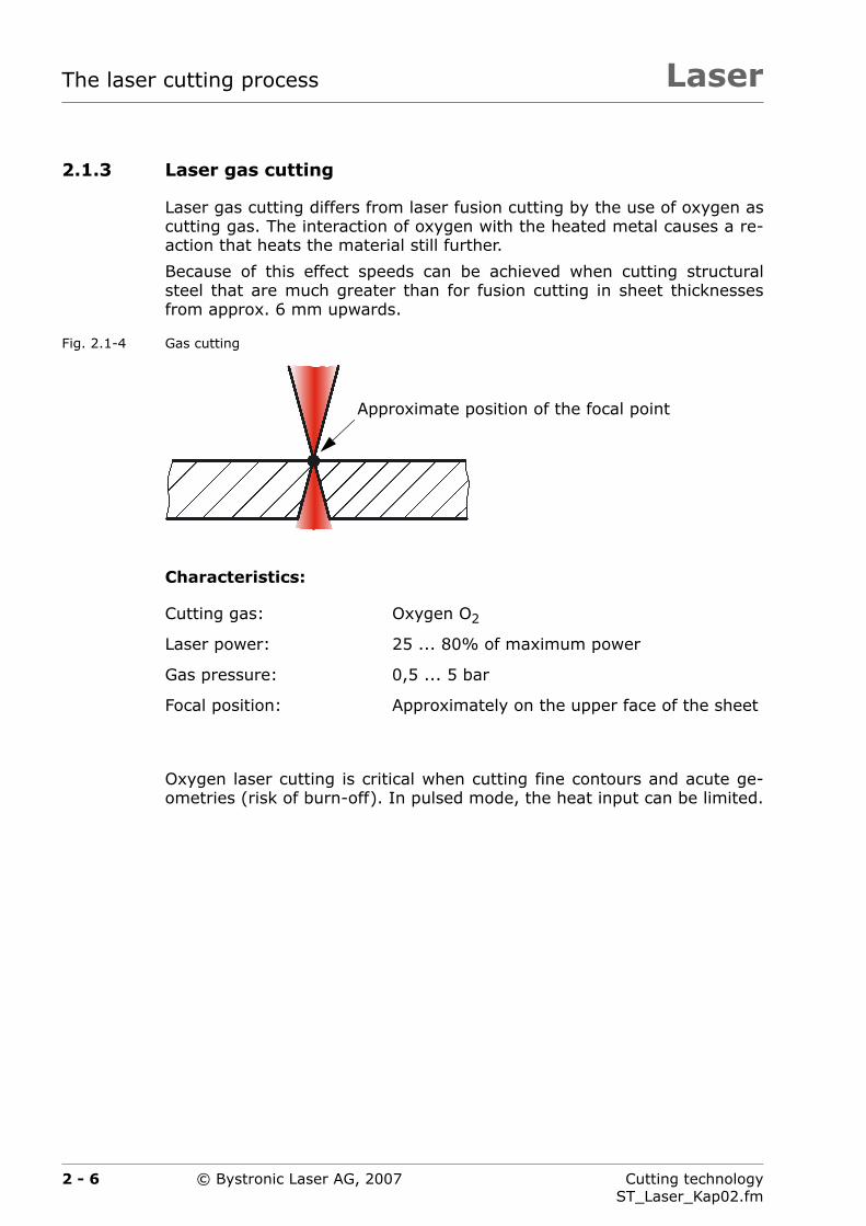
2.1.3 Laser gas cutting
Laser gas cutting differs from laser fusion cutting by the use of oxygen ascutting gas. The interaction of oxygen with the heated metal causes a re-action that heats the material still further.
Because of this effect speeds can be achieved when cutting structuralsteel that are much greater than for fusion cutting in sheet thicknessesfrom approx. 6 mm upwards.
Fig. 2.1-4 Gas cutting
Characteristics:
Oxygen laser cutting is critical when cutting fine contours and acute ge-ometries (risk of burn-off). In pulsed mode, the heat input can be limited.
Cutting gas: Oxygen O2
Laser power: 25 ... 80% of maximum power
Gas pressure: 0,5 ... 5 bar
Focal position: Approximately on the upper face of the sheet
Approximate position of the focal point
2 - 6 Cutting technologyST_Laser_Kap02.fm
© Bystronic Laser AG, 2007
Laser The laser cutting process
2.1.4 Laser sublimation cutting
With laser sublimation cutting, the material is vaporized directly in the cut,without a liquid phase.
Laser sublimations cutting is not used in Bystronic laser cuttingmachines and is therefore only mentioned here for the sake ofcomprehensiveness.
2 - 7Cutting technologyST_Laser_Kap02.fm
© Bystronic Laser AG, 2007

LaserThe laser cutting process
2.2 Cutting process
By machining process is meant the interaction between the laser beam,cutting gas and workpiece.
Fig. 2.2-1 Process parameters
The zone in which this process occurs is known as the cutting front or cutfront. The laser power acting at the cutting front must heat the material tothe temperature required for phase transition of the material to smelt andvapor.
The cutting front is a practically vertical surface that is heated and fusedby the absorbed laser power.
In laser flame cutting, this melt zone is heated up further by the flow ofoxygen blown into the cutting gap and reaches temperatures close tothe boiling point of the material. This causes strong vaporization, lead-ing to ablation of the material. Simultaneously, the cutting gas ejectsmolten material from the underside of the workpiece.
In fusion cutting the gas blows out the liquid material and protects thecutting gap from oxidation.
The melt zone continues to move in the direction of cutting. This producesa continuous cutting gap.
Many of the processes that play an important role in laser cutting takeplace in this zone. An analysis of these processes allows important state-ments on laser cutting. For example, it is possible to estimate cuttingspeed and explain the formation of the characteristic striations.
Process parame-ters of
Laser Cutting gasMaterial Axis movement
2 - 8 Cutting technologyST_Laser_Kap02.fm
© Bystronic Laser AG, 2007

Laser The laser cutting process
2.2.1 Gas parameters
Gas type
Gas purity
Gas pressure
Nozzle diameter
Nozzle geometry
The gas pressure and the nozzle geometry influence the cut face rough-ness and the beading.
2.2.2 Cutting gas consumption
Cutting gas consumption depends on the nozzle diameter and the gaspressure.
For low-pressure cutting applications gas pressure is up to 5 bar, forhigh pressure cutting up to 20 bar.
The conventional cutting nozzle has a circular, conical orifice.
The distance between the nozzle orifice and the workpiece surface mustbe as small as possible. The smaller this distance, the greater is theproportion of the gas flow that actually enters the cut. Clearance dis-tances typically range from 0.5 to 1.5 mm.
2 - 9Cutting technologyST_Laser_Kap02.fm
© Bystronic Laser AG, 2007

LaserThe laser cutting process
2 - 10 Cutting technologyST_Laser_Kap02.fm
© Bystronic Laser AG, 2007

Laser
Chapter 3
3 Design and manufacture
This chapter describes the factors that influence the manufacturing pro-cess.
3 - 1Cutting technologyST_Laser_Kap03.fm
© Bystronic Laser AG, 2007

LaserDesign and manufacture
3 - 2 Cutting technologyST_Laser_Kap03.fm
© Bystronic Laser AG, 2007

Laser Design and manufacture
3.1 Factors influencing the manufacturing pro-cess
The following factors influence the manufacturing process:
The design options and limits
The working method and procedure
The interrelations between influence factors and parameters
Programming
Rules, advantages and hints
An optimum cutting result is already determined in the design process. Itis important that the designer is aware of the possibilities available in lasercutting machine design. Only then can a component be designed for theenvisaged function and optimum production.
The person responsible for creating the cutting plans must have detailedknowledge of the laser cutting machine. Ideally this person will have a lotof experience with laser cutting machines. Only in this way can cuttingplans be optimally adapted to the laser cutting machine.
Practice has shown that the ideal location for the programming station isclose to the laser cutting machine. This guarantees a constant transfer ofknowledge between operator and programmer.
This chapter builds upon the basic knowledge of machine oper-ating and programming. None of the basic functions are de-scribed here.Most descriptions are valid in general and are not restricted toindividual laser or machine types. The laser or machine type willbe mentioned in special cases.
3 - 3Cutting technologyST_Laser_Kap03.fm
© Bystronic Laser AG, 2007

LaserDesign and manufacture
3.2 Material specification
If nothing to the contrary is stated, the cutting technology data refers tothe following materials:
Structural steel Thickness: 1 ... 15 mm St 37-2
Thickness: 16 ... 25 mm RAEX 420MC
Rust and acid-resistant steel (without a protective film) X5CrNi 18 9
Aluminum (without protective film) AlMg 3
3 - 4 Cutting technologyST_Laser_Kap03.fm
© Bystronic Laser AG, 2007

Laser Design and manufacture
3.3 Design guidelines
When designing the parts to be cut the following guidelines should be ob-served. This contributes to a substantial simplification of the manufactur-ing process.
3.3.1 Sheet formats
The principal sheet formats are:
4 000 × 2 000 mm
4 000 × 1 500 mm
3 000 × 1 500 mm
2 500 × 1 250 mm
2 000 × 1 000 mm
3.3.2 Cutting gap width for laser cutting
The width of the cutting gap is a function of the focal length and the sheetthickness. This cutting gap width cannot be altered.
However, using the tool radius cutting parameter, it can be compensated(to guarantee dimensional accuracy).
Tab. 3.3-1 Guide values for cutting gap
Sheet thicknessin [mm]
1 3 5 8 12 15 20 25
Cutting gap in [mm] 0,15 0,20 0,25 0,40 0,50 0,50 0,60 0,65
It is possible to make only one cut in the width of the cuttinggap. This is used for strain relief cuts in the region of bends, forexample.
3 - 5Cutting technologyST_Laser_Kap03.fm
© Bystronic Laser AG, 2007

LaserDesign and manufacture
3.3.3 Orthogonality of the cut face
When laser cutting, the cuting gap does not lie exactly square to the sheetsurface. Per 10 mm of sheet thickness, the cut edges are up to 0.1 mmout of square.
Fig. 3.3-1 Out-of-square when cutting with oxygen (O2)
Fig. 3.3-2 Out-of-square when fusion cutting with nitrogen (N2)
The above geometries (Fig. 3.3-1 and Fig. 3.3-2) result from the selectedcutting process and cannot be altered.
The out-of-square is assessed according to DIN EN ISO 9013 (Classifica-tion of thermal cuts).
As a rule, the out-of-square with laser cutting is significantly better thanwith plasma cutting or thermal cutting.
0,1 mm
10
mm
0,1 mm10
mm
10
mm
0,1 mm
3 - 6 Cutting technologyST_Laser_Kap03.fm
© Bystronic Laser AG, 2007

Laser Design and manufacture
3.3.4 Roughness of the cut edges
The roughness of the cut edges increases with increasing material thick-ness.
Generally, the roughness values of the DIN EN ISO 9013 toleranceclass 2 are reached with laser cutting.An exception to this is the plasma cut in rust- and acid-resistant steel(see Chapter6.8 ›Plasma cut‹).
Minor changes to the roughness of the cut face can be made using thecutting parameters.
The following diagrams (Fig. 3.3-3, Fig. 3.3-4 and Fig. 3.3-5) show abasic summary of the roughness values Rz. These values were calcu-lated using a 4 400 W laser and may vary with other laser outputs.
Fig. 3.3-3 Guide values for rust and acid resistant steel with 4 400 W laser.
A Rust and acid-resistant steel, quality cut
B Rust and acid-resistant steel, plasma cut
C DIN EN ISO 9013 tolerance class 1
D DIN EN ISO 9013 tolerance class 2
E DIN EN ISO 9013 tolerance class 3
Ro
ug
hn
ess
Rz
in [
µm
]
Sheet thickness [mm]
C
D
E
A
B
3 - 7Cutting technologyST_Laser_Kap03.fm
© Bystronic Laser AG, 2007

LaserDesign and manufacture
Fig. 3.3-4 Guide values for structural steel with 4 400 W laser
Fig. 3.3-5 Guide values for aluminum with 4 400 W laser
A Structural steel, cutting gas nitrogen, N2
B Structural steel, cutting gas oxygen, O2
C DIN EN ISO 9013 tolerance class 1
D DIN EN ISO 9013 tolerance class 2
E DIN EN ISO 9013 tolerance class 3
Ro
ug
hn
ess
Rz
in [
µm
]
Sheet thickness [mm]
C
D
E
B
A
Ro
ug
hn
ess
Rz
in [
µm
]
Sheet thickness [mm]
C
D
E
3 - 8 Cutting technologyST_Laser_Kap03.fm
© Bystronic Laser AG, 2007

Laser Design and manufacture
3.3.5 Contour radii
As a basic rule, contours and corners should be rounded. Avoid sharp con-tours.
Advantages:
Shorter production times
Higher process reliability
Lower injury hazard
Improved visual impression
Tab. 3.3-2 Guide values for minimum radii at corners
The radii can be much greater than the minimum values in the table. Ifthe design does not allow for a radius, the corner can remain pointed. Ra-dii smaller than 0.8 mm are more difficult to manufacture than pointedcorners.
The Bysoft Technology wizard provides a simple method of rounding cor-ners.
Material Cutting gas
Sheet thicknessin [mm]
...
4
5..
.8
10
...
12
15
...
18
20
25
Structural steel Oxygen
O2
0,8 1,0 1,5 2,0 3,0 4,0
Rust and acid-resistant steel Nitrogen
N2
0,8 1,2 2,0 3,0 4,0 5,0
Aluminum 0,8 1,5 2,5 4,0 — —
Structural steel 0,8 1,5 — — — —
3 - 9Cutting technologyST_Laser_Kap03.fm
© Bystronic Laser AG, 2007

LaserDesign and manufacture
3.3.6 Sheet thickness
3.3.6.1 Select small sheet thicknesses
As far as the stability allows, the most effective material saving isachieved by reducing the sheet thickness. Not only does this lead to lessweight, cutting and handling times are also shortened drastically.
However, the reduction in material thickness is only justified if it is notachieved by additional manufacturing effort, such as welded reinforce-ments.
3.3.6.2 Select equal sheet thicknesses
For single piece production it is expedient to fabricate all sheet compo-nents of an assembly from as few different sheet thicknesses as possible.The production times can be vastly reduced in this manner.
3 - 10 Cutting technologyST_Laser_Kap03.fm
© Bystronic Laser AG, 2007

Laser Design and manufacture
3.3.7 Common separating cut
If a part is designed so that two neighboring edges can be processed witha single cut, production time can be heavily shortened.
Fig. 3.3-6 Single piece production (each piece is cut separately)
Fig. 3.3-7 Production with common cut edges
Production with common cut edges is primarily suitable for all strip-shaped parts from 500 mm long upwards. This can, in some cases, drasti-cally reduce manufacturing time and minimize waste.
Various parts can be nested within each other so that they can all be man-ufactured with common separating cuts.
Bysoft supports this procedure with simple functions.
3 - 11Cutting technologyST_Laser_Kap03.fm
© Bystronic Laser AG, 2007

LaserDesign and manufacture
3.3.8 Hanging hole for the paint shop
A hole for hanging the workpiece can be of great assistance when paint-ing. Make sure that these holes are made at the edge of the workpiece, sothat positioning pins can be easily used.
3.3.9 Edge deformation
On the faces of sheets, deformation of the edges can occur due to com-pression of the material during bending. A corner relief must therefore becut when:
The face needs to lie flat
A part is placed in a slot which is bent
Fig. 3.3-8 Corner reliefs
Min. hole diameter for lightweight parts: ∅4 mm
Min. hole diameter for heavy parts: ∅6 mm
Sheet thicknessin [mm]
Radius and corner reliefin [mm]
r t
up to 3.0 8,0 1,0
3,0 ... 8,0 15,0 2,0
8,0 ... 15,0 20,0 4,0
15,0 ... 20,0 25,0 5,0
rr
tt
3 - 12 Cutting technologyST_Laser_Kap03.fm
© Bystronic Laser AG, 2007
Laser Design and manufacture
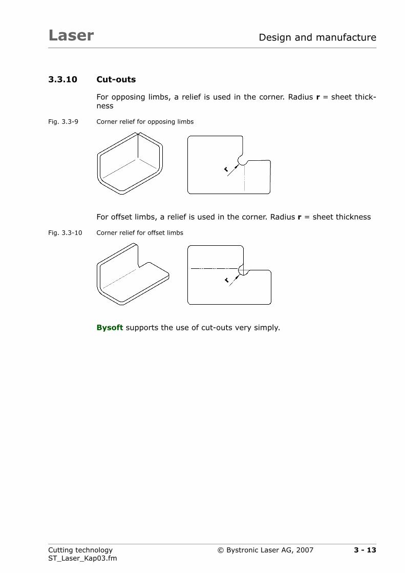
3.3.10 Cut-outs
For opposing limbs, a relief is used in the corner. Radius r = sheet thick-ness
Fig. 3.3-9 Corner relief for opposing limbs
For offset limbs, a relief is used in the corner. Radius r = sheet thickness
Fig. 3.3-10 Corner relief for offset limbs
Bysoft supports the use of cut-outs very simply.
rr
3 - 13Cutting technologyST_Laser_Kap03.fm
© Bystronic Laser AG, 2007

LaserDesign and manufacture
3.3.11 Tongues (bent parts only)
Incisions for tongues are always to be drawn as continuous lines with theappropriate gap width. This ensures the simplest manufacture.
The tongue width should not be less than 50 mm. Gap width x = sheetthickness
Fig. 3.3-11 Incisions for tongues
poorly designed
well designed
x50
3 - 14 Cutting technologyST_Laser_Kap03.fm
© Bystronic Laser AG, 2007

Laser Design and manufacture
3.3.12 Relief cuts
Holes and slots located too close to the bending line are deformed duringbending.
If the minimum side length cannot be achieved even with a smaller die, arelief cut must be made.
Fig. 3.3-12 Stress relief cut
a Stress relief cut
b Bending line
a
b
3 - 15Cutting technologyST_Laser_Kap03.fm
© Bystronic Laser AG, 2007
LaserDesign and manufacture
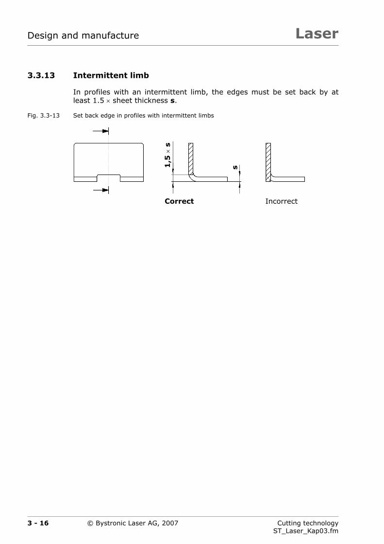
3.3.13 Intermittent limb
In profiles with an intermittent limb, the edges must be set back by atleast 1.5 × sheet thickness s.
Fig. 3.3-13 Set back edge in profiles with intermittent limbs
Correct Incorrect
s1,5
×s
3 - 16 Cutting technologyST_Laser_Kap03.fm
© Bystronic Laser AG, 2007

Laser Design and manufacture
3.3.14 Tongue and slot joints
Aligning, centering and tacking can be saved during welding by using con-nectors. A welding gauge can also be dispensed with.
Ensure that the connector is manufactured with approx. 0.5 mm play, sothat individual parts can be easily fitted together.
Examples
Fig. 3.3-14 Straight joint
Fig. 3.3-15 Right-angled joint
Fig. 3.3-16 Multipart holder
3 - 17Cutting technologyST_Laser_Kap03.fm
© Bystronic Laser AG, 2007

LaserDesign and manufacture
3.3.15 Marking similar parts
Marking is carried out using the engrave function. This is a simple way toadd part numbers, positioning aids and the such like to the parts in thesame work sequence as the laser cutting (also see section6.9 ›Engraving‹).
Bysoft supports the programming of part numbers or consecutive num-bers.
Examples
Fig. 3.3-17 Engraved part number
Fig. 3.3-18 Engraved positioning aid
Laser engraved
The manufacturing process is prolonged by engraving markings.
Laser engraved
3 - 18 Cutting technologyST_Laser_Kap03.fm
© Bystronic Laser AG, 2007

Laser
Chapter 4
4 Programming
This chapter provides information about technologies for piercings, initialcuts and contours for various materials and lasers in use.
4 - 1Cutting technologyST_Laser_Kap04.fm
© Bystronic Laser AG, 2007

LaserProgramming
4 - 2 Cutting technologyST_Laser_Kap04.fm
© Bystronic Laser AG, 2007
Laser Programming
4.1 General instructions
Optimal programming substantially simplifies the cutting process and re-duces manufacturing times while maintaining optimum part quality.
It is therefore important that the programmer is familiar with the lasercutting machine and exchanges experience with the operating personnel.
Bysoft allows for optimum programming. Under certain cir-cumstances, other software products do not make full use ofthe potential of the laser cutting machine.
4 - 3Cutting technologyST_Laser_Kap04.fm
© Bystronic Laser AG, 2007

LaserProgramming
4.2 Technology wizard
The technology wizard provides support when programming parts. Thisdemands less detailed knowledge of the technology of the programmer.An optimum cutting result is achieved substantially faster.
The following technologies are set up automatically for each laser, materi-al, sheet thickness and geometry.
Fig. 4.2-1 Technologies which are automatically set
A Piercing type (CW / pulse)
B Initial cut type (straight / straight line with arc), initial cut lengthand technology on the initial cut
C Technology set for contour (CW / pulse / process macro) as a func-tion of the material, sheet thickness and the area to be cut
The cutting parameters of the laser cutting machine are opti-mized for the wizard technologies. In general, the technologywizard should always be used. This allows optimum exploitationof the various options.
A
B
C
4 - 4 Cutting technologyST_Laser_Kap04.fm
© Bystronic Laser AG, 2007

Laser Programming
Fig. 4.2-2 Specify technology (in Bypart)
A Select material
B Select sheet thickness
C Select laser cutting machine
D Select technology table
C
B
A
D
4 - 5Cutting technologyST_Laser_Kap04.fm
© Bystronic Laser AG, 2007

LaserProgramming
4.2.1 Functionality examples
The following examples (Fig. 4.2-4, Fig. 4.2-5 and Fig. 4.2-6) illustratehow the initial cuts and technologies are automatically selected in an opti-mum way by the technology wizard for the same part, but with a differentmaterial and sheet thickness.
Fig. 4.2-3 Part to be cut
A Hole ∅14 mm
B Square hole 8 x 8 mm
C Outer contour
25
∅14
60
88
A BC
4 - 6 Cutting technologyST_Laser_Kap04.fm
© Bystronic Laser AG, 2007

Laser Programming
Fig. 4.2-4 Technology for cutting structural steel, 12 mm thick
Material: Structural steel
Sheet thickness: 12 mm
Laser module: 5 200 W
Cutting gas: Oxygen O2
Bore ∅14 mm
Initial cut type Straight line with arc
Initial cut length Start in center
Piercing Pulsed (CPP)
Cutting Process macro 1
Square hole 8 x 8 mm
Initial cut type Straight
Initial cut length Start in center
Piercing Pulsed (CPP)
Cutting Pulsed
Outer contour
Initial cut type Straight line with arc
Initial cut length 12 mm
Piercing Pulsed (CPP)
Cutting CW
4 - 7Cutting technologyST_Laser_Kap04.fm
© Bystronic Laser AG, 2007

LaserProgramming
Fig. 4.2-5 Technology for cutting structural steel, 6 mm thick
Material: Structural steel
Sheet thickness: 6 mm
Laser module: 5 200 W
Cutting gas: Oxygen O2
Bore ∅14 mm
Initial cut type Straight
Initial cut length 6 mm
Piercing Pulsed (CPP)
Cutting CW
Square hole 8 x 8 mm
Initial cut type Straight
Initial cut length Start in center
Piercing Pulsed (CPP)
Cutting Process macro 1
Outer contour
Initial cut type Straight
Initial cut length 6 mm
Piercing Pulsed (CPP)
Cutting CW
4 - 8 Cutting technologyST_Laser_Kap04.fm
© Bystronic Laser AG, 2007

Laser Programming
Fig. 4.2-6 Technology for cutting rust- and acid-resistant steel, 4 mm thick
Material: Rust and acid-resistant steel
Sheet thickness: 4 mm
Laser module: 5 200 W
Cutting gas: Nitrogen N2
Bore ∅14 mm
Initial cut type Straight line with arc
Initial cut length 6 mm
Piercing CW
Cutting CW
Square hole 8 x 8 mm
Initial cut type Straight line with arc
Initial cut length Start in center
Piercing CW
Cutting CW
Outer contour
Initial cut type Straight line with arc
Initial cut length 6 mm
Piercing CW
Cutting CW
4 - 9Cutting technologyST_Laser_Kap04.fm
© Bystronic Laser AG, 2007

LaserProgramming
4.2.2 Adaptations
For special applications it is possible to adapt the existing technology wiz-ard or to program a new one.
The Bypart Online Help describes the procedure in detail.
4.2.3 Special features
When using the process macro Scanning1), the technology wizard mustremain inactivated.
1) See Chapter 8.2.6 ›Thin sheet machining using scanning‹ for further details.
4 - 10 Cutting technologyST_Laser_Kap04.fm
© Bystronic Laser AG, 2007

4 - 11 Cutting technologyST_Laser_Kap04.fm
Lase Programming
4.2.4
Tab. 4.2-1
Laser module
3 000 W 4 400 W / 5 200 W /6 000 W
≤ T D > T D ≤ T D > T
lsed CW Pulsed CW
lsed CW Pulsed CW
lsed CW Pulsed Pulsed
lsed CW Pulsed Pulsed
lsed CW Pulsed Pulsed
⎯ ⎯ Pulsed Pulsed
W CW CW CW
W CW CW CW
W CW CW CW
⎯ ⎯ CW CW
© Bystronic Laser AG, 2007
r
Guidelines for piercings
Various piercing types and their applications
Material Cutting gas
2 200 W
T in [mm] D ≤ T D > T D
Str
uct
ura
l st
eel
0,6 ... 1,5
OxygenO2
Pulsed CW Pu
2,0 ... 3,0 Pulsed CW Pu
4,0 ... 8,0 Pulsed CW Pu
10,0 ... 12,0 Pulsed CW Pu
15,0 ... 20,0 ⎯ ⎯ Pu
21,0 ... 25,0 ⎯ ⎯
Str
uct
ura
l st
eel 0,6 ... 1,5
NitrogenN2
CW CW C
2,0 ... 4,0 CW CW C
5,0 ... 6,0 ⎯ ⎯ C
6,0 ... 8,0 ⎯ ⎯

4 - 12 Cutting technologyST_Laser_Kap04.fm
Lase Programming
W CW CW CW
W CW CW CW
W CW CW CW
⎯ ⎯ CW CW
⎯ ⎯ Pulsed Pulsed
W CW CW CW
W CW CW CW
W CW CW CW
⎯ ⎯ Pulsed Pulsed
Laser module
3 000 W 4 400 W / 5 200 W /6 000 W
≤ T D > T D ≤ T D > T
© Bystronic Laser AG, 2007
r
rust
- an
daci
d-r
esis
tant
stee
l
0,6 ... 1,5
NitrogenN2
CW CW C
2,0 ... 6,0 CW CW C
8,0 ... 10,0 ⎯ ⎯ C
12,0 ... 14,0 ⎯ ⎯
15,0 ... 20,0 ⎯ ⎯
Alu
min
um
0,6 ... 1,5
NitrogenN2
CW CW C
2,0 ... 5,0 CW CW C
6,0 ... 7,0 ⎯ ⎯ C
8,0 ... 12,0 ⎯ ⎯
D = Bore diameter
T = Sheet thickness
Material Cutting gas
2 200 W
T in [mm] D ≤ T D > T D
T
D

4 - 13 Cutting technologyST_Laser_Kap04.fm
Lase Programming
4.2.5
Tab. 4.2-2
efined as appropriate. The following table containschnology wizard specifies and optimizes the initial
Initial cut type
n- Initial cut length Length Radius
3 mm
5 mm
8 mm
12 mm 1 mm
20 mm 1,5 mm
25 mm 3 mm
© Bystronic Laser AG, 2007
r
Guidelines for initial cut types
Various initial cut types and their applications
If Bysoft is not employed for programming, the initial cuts must be dbase values from which Bysoft selects the initial cuts. However, the tecuts much more precisely.
Material Technology on the initial cut.
Cutting gas
T in [mm] Directly on cotour
Str
uct
ura
l st
eel
1,0 ... 1,5 As contour
Oxy
gen
O2
Possible
2,0 ... 3,0 As contour
4,0 ... 8,0 As contour
10,0 ... 15,0 As contour
16,0 ... 20,0 As contour
21,0 ... 25,0 Process macro 1

4 - 14 Cutting technologyST_Laser_Kap04.fm
Lase Programming
3 mm
3 mm
4 mm
5 mm
8 mm
3 mm
5 mm 1 mm
8 mm 1,5 mm
3 mm
5 mm
8 mm 1,5 mm
12 mm 2 mm
12 mm 3 mm
Initial cut type
n- Initial cut length Length Radius
© Bystronic Laser AG, 2007
r
Str
uct
ura
lst
eel
1,0 ... 1,5 Pulsed
Oxy
gen
O2
2,0 ... 3,0 Pulsed
4,0 ... 8,0 Pulsed
10,0 ... 15,0 Pulsed
16,0 ... 20,0 Pulsed
Str
uct
ura
lst
eel
1,0 ... 1,5 As contour
Nitro
gen
N2
Possible
2,0 ... 3,0 As contour
4,0 ... 8,0 As contour
rust
- an
dac
id-r
esis
tant
stee
l
1,0 ... 1,5 As contourN
itro
gen
N2
Possible
2,0 ... 3,0 As contour
4,0 ... 6,0 As contour
8,0 ... 10,0 As contour
12,0 Process macro 2
Material Technology on the initial cut.
Cutting gas
T in [mm] Directly on cotour

4 - 15 Cutting technologyST_Laser_Kap04.fm
Lase Programming
3 mm
5 mm
8 mm 1,5 mm
10 mm
Initial cut type
n- Initial cut length Length Radius
© Bystronic Laser AG, 2007
r
Alu
min
um
1,0 ... 1,5 As contour
Nitro
gen
N2
Possible
2,0 ... 3,0 As contour
4,0 ... 6,0 As contour
8,0 ... 12,0 Process macro 2
T = Sheet thickness
Material Technology on the initial cut.
Cutting gas
T in [mm] Directly on cotour
T
4 - 16 Cutting technologyST_Laser_Kap04.fm
Lase Programming
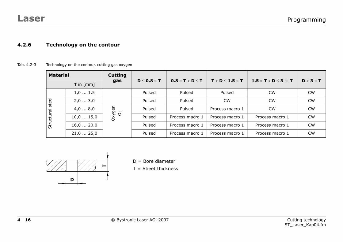
4.2.6
Tab. 4.2-3
T < D ≤ 1.5 × T 1.5 × T < D ≤ 3 × T D > 3 × T
Pulsed CW CW
CW CW CW
Process macro 1 CW CW
Process macro 1 Process macro 1 CW
Process macro 1 Process macro 1 CW
Process macro 1 Process macro 1 CW
© Bystronic Laser AG, 2007
r
Technology on the contour
Technology on the contour, cutting gas oxygen
Material Cutting gas D ≤ 0.8 × T 0.8 × T < D ≤ T
T in [mm]
Str
uct
ura
l st
eel
1,0 ... 1,5
Oxy
gen
O2
Pulsed Pulsed
2,0 ... 3,0 Pulsed Pulsed
4,0 ... 8,0 Pulsed Pulsed
10,0 ... 15,0 Pulsed Process macro 1
16,0 ... 20,0 Pulsed Process macro 1
21,0 ... 25,0 Pulsed Process macro 1
D = Bore diameter
T = Sheet thicknessT
D

4 - 17 Cutting technologyST_Laser_Kap04.fm
Lase Programming
Tab. 4.2-4
5 × T 1.5 × T < D ≤ 3 × T D > 3 × T
CW CW
CW CW
CW CW
CW CW
cro 1 CW CW
CW CW
CW CW
cro 1 CW CW
cut and contour technology substantially finer thantween different machine types and sheet versions.
© Bystronic Laser AG, 2007
r
Technology on the contour, cutting gas nitrogen
Material Cutting gas D ≤ T T < D ≤ 1.
T in [mm]
Str
uct
ura
lst
eel
1,0 ... 3,0
Nitro
gen
N2
CW CW
4,0 ... 8,0 Process macro 1 CW
rust
- an
daci
d-r
esis
tant
stee
l
1,0 ... 3,0
Nitro
gen
N2
CW CW
4,0 ... 8,0 Process macro 1 CW
10,0 ... 12,0 Process macro 1 Process ma
Alu
min
um 1,0 ... 3,0
Nitro
gen
N2
CW CW
4,0 ... 8,0 Process macro 1 CW
10,0 ... 12,0 Process macro 1 Process ma
The Bysoft Technology wizard optimizes the piercing, initial given in Tab. 4.2-1 ... Tab. 4.2-4. Bysoft also differentiates be

LaserProgramming
4.3 Piercing and initial cuts
The initial cuts should always reach their intended length and must beplaced accordingly.
Piercing causes the sheet to heat up very strongly. Strategic positioning ofpiercing points and adequate length of initial cuts can help prevent heatbuild-up.
An additional function is available on the 4 400 W, 5 200 W and 6 000 Wlasers: CPP (Controlled Pulsed Piercing). This reduces the heat inputgreatly when piercing. See Chapter 6.11.2 ›CPP(Controlled Pulsed Pierc-ing)‹.
At the limit thickness a radius initial cut is unavoidable for a uniform cut-ting process.
Fig. 4.3-1 Poorly selected initial cuts
Fig. 4.3-2 Well selected initial cuts with additional radius initial cut
Heat build-up, possible deterioration of cut-ting quality
4 - 18 Cutting technologyST_Laser_Kap04.fm
© Bystronic Laser AG, 2007
Laser Programming
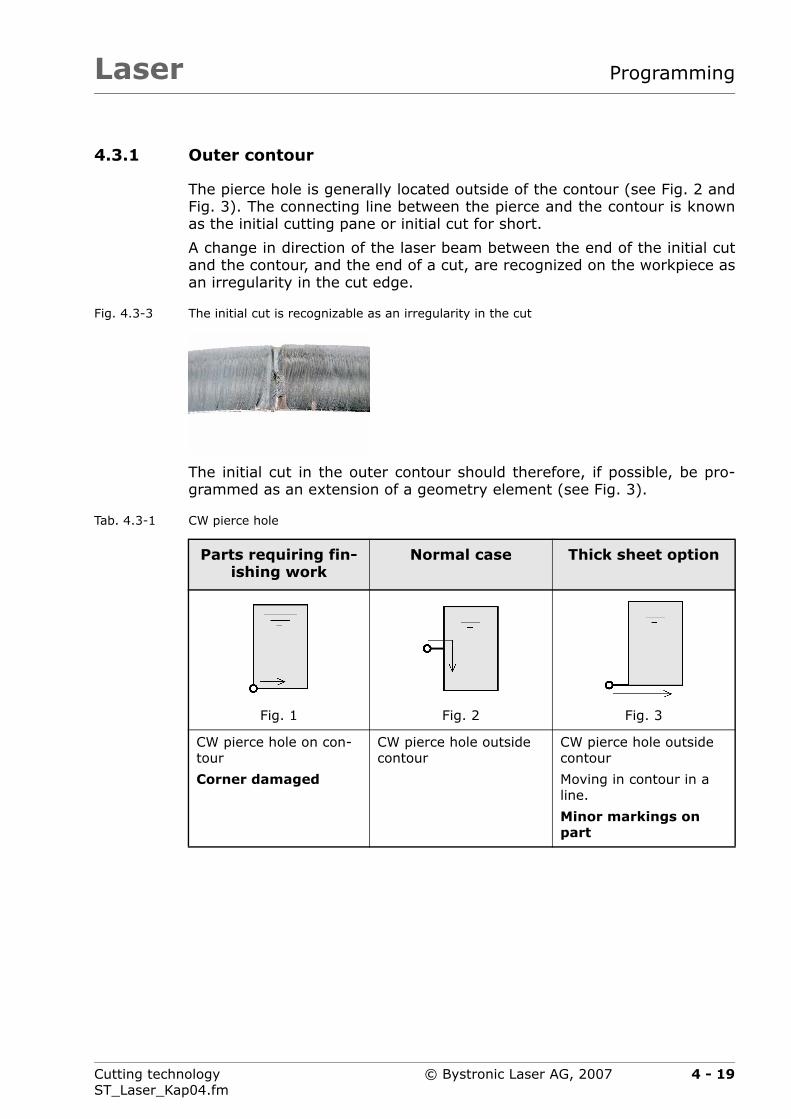
4.3.1 Outer contour
The pierce hole is generally located outside of the contour (see Fig. 2 andFig. 3). The connecting line between the pierce and the contour is knownas the initial cutting pane or initial cut for short.
A change in direction of the laser beam between the end of the initial cutand the contour, and the end of a cut, are recognized on the workpiece asan irregularity in the cut edge.
Fig. 4.3-3 The initial cut is recognizable as an irregularity in the cut
The initial cut in the outer contour should therefore, if possible, be pro-grammed as an extension of a geometry element (see Fig. 3).
Tab. 4.3-1 CW pierce hole
Parts requiring fin-ishing work
Normal case Thick sheet option
Fig. 1 Fig. 2 Fig. 3
CW pierce hole on con-tour
Corner damaged
CW pierce hole outside contour
CW pierce hole outside contour
Moving in contour in a line.
Minor markings on part
4 - 19Cutting technologyST_Laser_Kap04.fm
© Bystronic Laser AG, 2007

LaserProgramming
Various initial cut types can be employed within a part. This allows anacute corner (A), for example, to be cut optimally.
Fig. 4.3-4 Various initial cuts
4.3.2 Inner contour (cut-outs)
With small inside contours it is important that the heat generated duringpiercing can be dissipated before cutting begins.
The initial cutting pane may not be programmed in tight corners andshould be designed with the largest possible angle to the contour. This fa-cilitates heat dissipation.
Fig. 4.3-5 Small inner contours
A
unsuitable suitable
4 - 20 Cutting technologyST_Laser_Kap04.fm
© Bystronic Laser AG, 2007

Laser Programming
4.4 Using process macros
The Bysoft Technology wizard assigns process macros automatically.
Tab. 4.4-1 Process macros
One or more contours which are assigned a process macro during pro-gramming with Bysoft can be cut with other cutting parameters.
This has the advantage that difficult parts or sections of contour (e.g. gearteeth) can be better optimized.
Fig. 4.4-1 Gear teeth cut with process macro
Process macro Description
1 Automatically used by the Technology wizard for small contours. See Tab. 4.2-3 and Tab. 4.2-4
2 Automatically used by the Technology wizard for the ini-tial cut in thick sheets . See Tab. 4.2-2
3 and 4 Available for customer-specific applications.
5 Reserved for vaporizing films (e.g. on rust and acid-re-sistant steel).
The vaporizing is programmed in Bywork. The corre-sponding cutting parameters are saved.
A Process macro 3
B CW
A
B
B
B
4 - 21Cutting technologyST_Laser_Kap04.fm
© Bystronic Laser AG, 2007

LaserProgramming
4.5 Radii on inner and outer contours
As a basic rule, you should avoid sharp contours when working with la-sers. It is far simpler to cut a radius when changing direction.
Advantages:
corners do not burn,
time saving thanks to continuous process,
clean laser part,
Hazard of injury on part is smaller
Tab. 4.5-1 Minimum radii for outer and inner contours in [mm]
Material Cutting gas Sheet thicknessin [mm]
...
4
5..
.8
10
...
12
15
...
18
20
25
Structural steel Oxygen O2 0,8 1,0 1,5 2,0 3,0 4,0
Structural steel Nitrogen N2 0,8 1,5 — — — —
Rust and acid-resis-tant steel
Nitrogen N2 0,8 1,2 2,0 3,0 4,0 —
Aluminum Nitrogen N2 0,8 1,5 2,5 — — —
Parts quality may suffer or parts may be rejected if radii are lessthan the minimum radii.
4 - 22 Cutting technologyST_Laser_Kap04.fm
© Bystronic Laser AG, 2007

Laser Programming
4.6 Cutting-time calculation
The result of the cutting-time calculation is only a rough guide to the ex-pected process time on the laser cutting machine. The effective processtime can differ significantly from this however.
The result from the cutting-time calculation must not be usedas a basis for quotations.
4 - 23Cutting technologyST_Laser_Kap04.fm
© Bystronic Laser AG, 2007

LaserProgramming
4 - 24 Cutting technologyST_Laser_Kap04.fm
© Bystronic Laser AG, 2007

Laser
Chapter 5
5 Cutting parameters
This chapter describes the procedure for the optimization of cutting pa-rameters.
5 - 1Cutting technologyST_Laser_Kap05.fm
© Bystronic Laser AG, 2007

LaserCutting parameters
5 - 2 Cutting technologyST_Laser_Kap05.fm
© Bystronic Laser AG, 2007
Laser Cutting parameters
5.1 General instructions
The cutting parameters for the permitted materials and cuttable sheetthicknesses are provided.
The default parameters are given for metric sheet thicknesses. Countriesusing different dimensional units (e.g. inches, Gauge No.) must use thenext closest metric cutting parameters. See section 5.5 ›Cutting parame-ters for different dimensional units‹
The cutting parameters assume a minimum radius for each geometry (seesection 3.3.5 ›Contour radii‹). Parts quality may suffer or parts may be re-jected if parts have a smaller radius.
The parameters for CPP piercing must be adjusted to suit the individualsheet qualities.
5 - 3Cutting technologyST_Laser_Kap05.fm
© Bystronic Laser AG, 2007

LaserCutting parameters
Before one can modify the cutting parameters correctly, it is very impor-tant to know the following:
how the part is programmed
which technology is being used
The following example shows the technologies which are automatically se-lected by the Technology wizard.
Fig. 5.1-1 Example: Structural steel, 8 mm thick
A Text Engraving
B Hole ∅4 mm Pulsed piercing
Pulsed cutting
C Longhole CW piercing
Cut with process macro 1
D Gear teeth CW piercing
Cut with process macro 1
E Outer contour CW piercing
CW cutting
A
B
C
D
E
5 - 4 Cutting technologyST_Laser_Kap05.fm
© Bystronic Laser AG, 2007

Laser Cutting parameters
It is important that during cutting you closely note the operations forwhich a parameter needs to be edited.
Normally, only very few parameters should need editing. Below are someexamples of how to quickly and purposefully achieve the optimum results.
Tab. 5.1-1 Cutting operations with the corresponding parameters
Cutting operation Parameter concerned
CW piercing CW piercing mode
Piercing time continuous wave mode
Laser power, piercing
Gas pressure CW piercing
Nozzle clearance height for piercing
Lead-in Acceleration factor for initial cut
Gas ramp, CW piercing/cutting
Possibly all CW parameters of process macro 2 (with thick sheets)
Outer contour Feed, continuous wave mode
Laser power, cutting
Gas pressure CW cutting
Nozzle type
Nozzle clearance height for cutting
5 - 5Cutting technologyST_Laser_Kap05.fm
© Bystronic Laser AG, 2007
LaserCutting parameters
5.2 Adapting cutting parameters
Cutting parameters are scalable values with a direct influence on the cut-ting process. The original cutting parameters are optimized for maximumprocess reliability.
A set of cutting parameters is supplied with every laser cutting machine.They are optimized to cut certain materials. Nevertheless, it is possiblethat the parameters deliver unsatisfactory cutting results. Below, the re-quirements and the procedure for obtaining better cutting results in suchcases are described.
For laser cutting there are numerous parameter that in part also exert amutual influence. Here, the five principal parameters with which the cutquality can be optimized are listed:
Focal position
Laser power
Gas pressure
Feed rate
Nozzle distance
The adaptations are only valid for simple contours such as straight lines.
The cutting quality in a straight line cut-out only is evaluated(directions x+, x-, y+ and y-). Interpolated cutting directions,such as radii, diagonal cuts or initial cuts, for example, are nottaken into consideration.
5 - 6 Cutting technologyST_Laser_Kap05.fm
© Bystronic Laser AG, 2007
Laser Cutting parameters
5.2.1 Reasons for parameter adaptations
Different material composition
Tolerance deviations in sheet thickness
Varying surface finish qualities
Large temperature differences of the materials used(reference temperature = +20 °C)
5.2.2 Requirements for parameter adaptations
The following requirements must be fulfilled in order to achieve good cutquality by adapting the principal parameters:
The laser cutting machine and the laser source must be in perfect con-dition.
Lens in cutting head must be free of faults (see chapter Operating in-structions).
The cutting head and the nozzle must correspond to the data in the re-spective cutting parameters.
Avoid overwriting the original cutting parameters!
The edited parameters can be saved respectively with a newmaterial designation or new additional information.
Only use original nozzles and lenses.
After adapting a parameter it is recommended to print it andstore it in a folder using the Paramview application in theBysoft 6 Toolbox.
5 - 7Cutting technologyST_Laser_Kap05.fm
© Bystronic Laser AG, 2007

LaserCutting parameters
5.3 Optimization of cutting parameters
5.3.1 Procedure
Before a new material is cut, a cutting test must be carried out. If the testreveals problems with the cutting quality, these problems can be correctedby adapting the original cutting parameter.
To facilitate the adaptation and testing of cutting parameters, cuttingplans are stored on the computer in the Acceptance folder, for the re-spective laser type. Use the Ab_gross.lcc cutting plan for the test. Thistakes all four cuts in x- and y-direction into consideration.
The following sequence for optimizing the cutting quality should be ad-hered to:
1. Load the shuttle table with the main sheet to be cut and move it tothe machining position.
2. Select the WORK – Job list view on the user interface, create thecutting job and assign the desired cutting parameters (see Operat-ing instructions).
Cutting plan Ab_gross.lcc or Ab_klein.lcc
Cutting parameters based on the material to be cut
3. The evaluation of the cutting quality is based on the information giv-en in chapter 11 ›Cut evaluation‹.
The further procedure for cutting optimization can be derived fromthe possible causes and their remedies listed here. If a number ofoptions are given, the following sequence should be adhered to.
Sequence when specifying cutting parameters
Step Cutting with O2 Cutting with N2
1. Focal position Focal position
2. Laser power Feed rate ±10% OK
3. Gas pressure Laser power
4. Feed rate ±10% OK Gas pressure
5. Nozzle distance Nozzle distance
5 - 8 Cutting technologyST_Laser_Kap05.fm
© Bystronic Laser AG, 2007

Laser Cutting parameters
4. The parameter values can be edited in the WORK – Parametersview.Edit only one cutting parameter at a time and then observe the ef-fects (also see Chapter 11 ›Cut evaluation‹).
5. Activate the STOP ZERO stop button before cutting. Machining isstopped at the origin of the cutting plan or at the origin of each indi-vidual part.
A message appears in the status bar each time, which must be con-firmed with CONT or STOP.
6. Repeat the cutting test with the edited parameters until a good cutresult is achieved.
7. Save the edited cutting parameters under a new file name (function:Save as).
The edited parameters can be saved respectively with a new materialdesignation or new additional information.
5 - 9Cutting technologyST_Laser_Kap05.fm
© Bystronic Laser AG, 2007
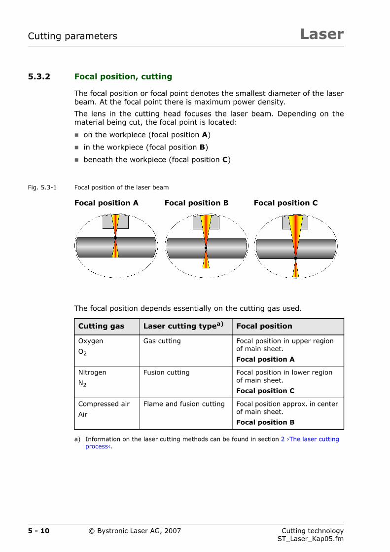
LaserCutting parameters
5.3.2 Focal position, cutting
The focal position or focal point denotes the smallest diameter of the laserbeam. At the focal point there is maximum power density.
The lens in the cutting head focuses the laser beam. Depending on thematerial being cut, the focal point is located:
on the workpiece (focal position A)
in the workpiece (focal position B)
beneath the workpiece (focal position C)
Fig. 5.3-1 Focal position of the laser beam
The focal position depends essentially on the cutting gas used.
Focal position A Focal position B Focal position C
Cutting gas Laser cutting typea)
a) Information on the laser cutting methods can be found in section 2 ›The laser cutting process‹.
Focal position
Oxygen
O2
Gas cutting Focal position in upper region of main sheet.
Focal position A
Nitrogen
N2
Fusion cutting Focal position in lower region of main sheet.
Focal position C
Compressed air
Air
Flame and fusion cutting Focal position approx. in center of main sheet.
Focal position B
5 - 10 Cutting technologyST_Laser_Kap05.fm
© Bystronic Laser AG, 2007
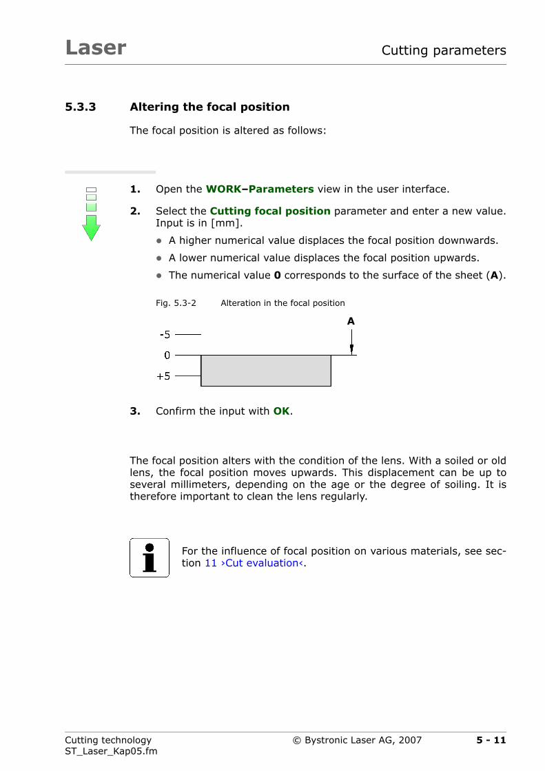
Laser Cutting parameters
5.3.3 Altering the focal position
The focal position is altered as follows:
1. Open the WORK–Parameters view in the user interface.
2. Select the Cutting focal position parameter and enter a new value.Input is in [mm].
A higher numerical value displaces the focal position downwards.
A lower numerical value displaces the focal position upwards.
The numerical value 0 corresponds to the surface of the sheet (A).
3. Confirm the input with OK.
The focal position alters with the condition of the lens. With a soiled or oldlens, the focal position moves upwards. This displacement can be up toseveral millimeters, depending on the age or the degree of soiling. It istherefore important to clean the lens regularly.
Fig. 5.3-2 Alteration in the focal position
For the influence of focal position on various materials, see sec-tion 11 ›Cut evaluation‹.
A
5 - 11Cutting technologyST_Laser_Kap05.fm
© Bystronic Laser AG, 2007
LaserCutting parameters
5.3.4 Laser power, cutting
This parameter defines the laser power during cutting in continuous oper-ation (CW).
The Laser power, cutting can be altered as follows:
1. Open the WORK–Parameters view in the user interface.
2. Select the Laser power cutting parameter and enter a new value.Input is in [W].
3. Confirm the input with OK.
For the influence of laser power on various materials, see sec-tion 11 ›Cut evaluation‹.
5 - 12 Cutting technologyST_Laser_Kap05.fm
© Bystronic Laser AG, 2007

Laser Cutting parameters
5.3.5 Gas pressure, cutting
The gas pressure depends on the cutting gas used and the smallest nozzleused.
The gas pressure is altered as follows:
1. Open the WORK–Parameters view in the user interface.
2. Select the appropriate parameter for the gas pressure (gas type 1,gas type 2, or gas type 3) and enter a new value. Input is in [bar].
For oxygen (O2), a higher value produces a higher cutting tempera-ture and a rougher cut surface.For nitrogen (N2), the material is ejected better and cooled more.
3. Confirm the input with OK.
Parameters Used for
Gas pressure, cutting, gas type 1 Cutting with O2
Maximum gas pressure 10 bar.
Gas pressure, cutting, gas type 2 Cutting with N2
Maximum gas pressure 24 bar.
Gas pressure, cutting, gas type 3 Cutting with compressed air (optional)
Maximum pressure 12 bar.
For the influence of gas pressure on various materials, see sec-tion 11 ›Cut evaluation‹.
5 - 13Cutting technologyST_Laser_Kap05.fm
© Bystronic Laser AG, 2007

LaserCutting parameters
5.3.6 Feed rate, cutting
This parameter defines the feed rate during cutting in continuous opera-tion (CW).
The Feed rate, cutting is a variable quantity and is dependent on otherfactors.
Example:
The Feed rate, cutting can be altered as follows:
1. Open the WORK–Parameters view in the user interface.
2. Select the cutting feed rate parameter and enter a new value. In-put is in [mm/min].
3. Confirm the input with OK.
By reducing the feed rate by 10 ... 20% the quality or process reliabilitycan be greatly improved in almost all cases.
Maximum Feed rate, cutting
(with reduced quality)
6,0 m/min Corresponds to 100%
Saved original parameter Feed rate, cutting
5,4 m/min Corresponds to approx. 90%
Minimum cutting speed 4,2 m/min Corresponds to approx. 70%
If the minimum cutting speed can no longer be achieved dur-ing production, the laser cutting machine will need to bechecked by the manufacturer's service personnel.
For the influence of the cutting feed rate on various materials,see section 11 ›Cut evaluation‹.
5 - 14 Cutting technologyST_Laser_Kap05.fm
© Bystronic Laser AG, 2007

Laser Cutting parameters
5.3.7 Nozzle clearance height for cutting
This parameter defines the distance of the nozzle from the surface of theworkpiece during cutting.
The Nozzle clearance height for cutting can be altered as follows:
1. Open the WORK–Parameters view in the user interface.
2. Select the Nozzle clearance height for cutting parameter and en-ter a new value. Input is in [mm].
3. Confirm the input with OK.
Nozzle distance Effect
<1 mm Wear and soiling of the nozzle increase
>1 mm reduced cutting quality
Lower nozzle heating for plasma cutting
5 - 15Cutting technologyST_Laser_Kap05.fm
© Bystronic Laser AG, 2007
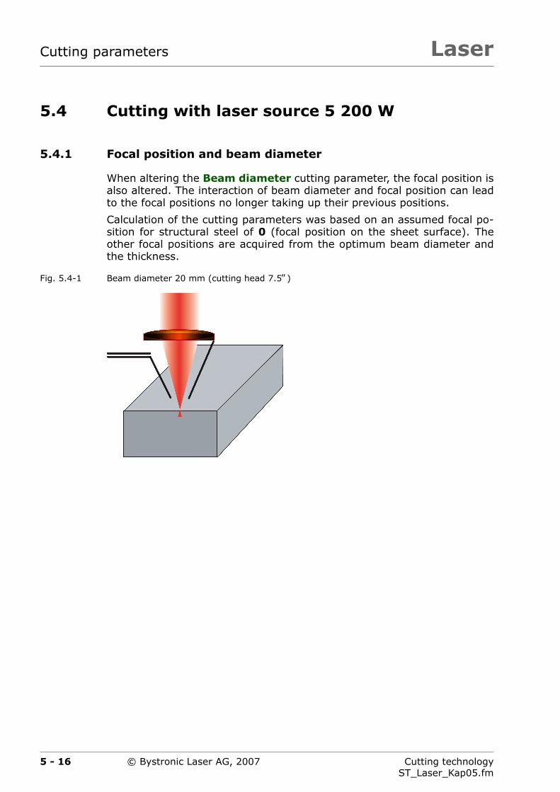
LaserCutting parameters
5.4 Cutting with laser source 5 200 W
5.4.1 Focal position and beam diameter
When altering the Beam diameter cutting parameter, the focal position isalso altered. The interaction of beam diameter and focal position can leadto the focal positions no longer taking up their previous positions.
Calculation of the cutting parameters was based on an assumed focal po-sition for structural steel of 0 (focal position on the sheet surface). Theother focal positions are acquired from the optimum beam diameter andthe thickness.
Fig. 5.4-1 Beam diameter 20 mm (cutting head 7.5″)
5 - 16 Cutting technologyST_Laser_Kap05.fm
© Bystronic Laser AG, 2007

Laser Cutting parameters
1. Alter beam diameter from 20 mm to 21 mm.
Fig. 5.4-2 Beam diameter 21 mm (cutting head 7.5″)
Displacement of focal position 1 mm downwards.
The focal position in the cutting parameter stays the same.
2. Focal position required to position the focal point on the sheet sur-face again for the altered beam diameter:
Focal position: -1 mm
Tab. 5.4-1 Displacing the focal position
Beam diameter Displacing the focal positionwith
Before After Focal length 5.0″ Focal length 7.5″
20 mm 19 mm approx. 0.5 mmupwards
approx. 1 mmupwards
20 mm 21 mm approx. 0.5 mmdownwards
approx. 1 mmdownwards
5 - 17Cutting technologyST_Laser_Kap05.fm
© Bystronic Laser AG, 2007

LaserCutting parameters
5.5 Cutting parameters for different dimensional units
The default parameters are given for metric sheet thicknesses. Countriesusing different dimensional units (e.g. inches, Gauge No.) must use thenext closest metric cutting parameters, as shown in Tab. 5.5-1.
Tab. 5.5-1 Cutting parameters to use for different dimensional units
Sheet thickness
in [mm] in [inches] in [Gauge No]
1,0 0,040 19
1,5 0,060 16
2,0 0,074 14
2,5 0,104 12
3,0 0,125 11
4,0 0,160 8
5,0 0,187 7
6,0 0,250 ⎯
8,0 0,312 ⎯
10,0 0,375 ⎯
12,0 0,500 ⎯
15,0 0,625 ⎯
20,0 0,750 ⎯
25,0 1,000 ⎯
5 - 18 Cutting technologyST_Laser_Kap05.fm
© Bystronic Laser AG, 2007

Laser
Chapter 6
6 Machining process
This chapter provides information on cutting with various materials. Thischapter also includes cutting parameter adjustments for complex contours(such as acute-angled corners, radii, small contours, initial and end cuts,bores, etc..).
6 - 1Cutting technologyST_Laser_Kap06.fm
© Bystronic Laser AG, 2007
LaserMachining process
6 - 2 Cutting technologyST_Laser_Kap06.fm
© Bystronic Laser AG, 2007
Laser Machining process
6.1 General instructions
To ensure a reliable cutting process, it must be ensured that no cut sheetparts remain erect which could collide with the cutting head. This can beensured by using microjoints, welding points or by cutting inside parts.
During the laser cutting process, the sheet must not undergo deformationor stand erect enough to produce a collision with the cutting head, bridgeor machine frame.
6 - 3Cutting technologyST_Laser_Kap06.fm
© Bystronic Laser AG, 2007

LaserMachining process
6.2 Various technologies
Tab. 6.2-1 Operating modes and applications
Operating mode Usage Example
Continuous mode (CW)
Low pressure cutting
Normal cutting
High-pressure cutting
Structural steel cut with ox-ygen (O2)
Aluminum cut with nitrogen (N2)
Rust and acid-resistant steel cut with Nitrogen N2
A relatively fine cut results from continuous power op-erating
Modulation (MOD) Cutting corners
Accelerating and braking
With modulation activated the laser power is automati-cally adjusted to the axes speed.
This prevents corners from getting burnt off.
Normal pulse (NP) Piercing
Small contours
Structural steel example:
Small piercings on contour (after microjoint)
Small bores down to ∅1/2 sheet thickness
Fine contours
Normal pulse (NP) CPP (Controlled Pulsed Piercing)
Only with laser sources 4 400 W5 200 W6 000 W
Piercing in structural steel with oxygen O21 ... 25 mm
Piercing in rust and acid-re-sistant steel16 ... 25 mm
Piercing in aluminum8 ... 15 mm
6 - 4 Cutting technologyST_Laser_Kap06.fm
© Bystronic Laser AG, 2007
Laser Machining process
6.3 Cutting structural steel
Structural steel can be cut to good quality with oxygen (O2). The laser isused in CW mode.
When laser cutting with oxygen the cut face is slightly oxidized. The highpressure cutting method can be utilized for sheet thicknesses of up to12 mm1), employing Nitrogen (N2) as the cutting gas. In this case, the cutedges are oxide-free.
Complex contours and bores (where diameter is smaller than the sheetthickness) are cut in pulsed mode with oxygen. This prevents burn-off onsharp corners and thin joints.
The greater the carbon content of the steel, the greater the hardeningof the cut edge and the more that acute-angled corners are burned off.
Sheets with alloy content are more difficult to cut than sheets withsmall content.
An oxidized or sand-blasted surface will produce a far poorer cut quali-ty.
Color markings on the surface of the sheet have a negative effect onthe cutting result.
With sheet thicknesses above 12 mm good results are achieved with la-ser sheets (e.g. Raex) and an oiled surface. This oil film reduces the ad-hesion of the slag on the surface and assists cooling considerably. Theoil film is not detrimental to the cutting result.
Use only fully killed steel where possible. Soiling in unkilled steel has avery negative effect on cutting results. Dressing rollers and inner stressalso influence the cutability.
1) Depends on the laser source output
6 - 5Cutting technologyST_Laser_Kap06.fm
© Bystronic Laser AG, 2007

LaserMachining process
For smaller contours with sheet thicknesses of 15 and 20 mm we recom-mend fine-grain steel, e.g.: RAEX 420 Laser from Rautaruukki Steelworks,Raahe (corresponds to a QStE 420 TM in accordance with EN, DIN, SEW).
This steel is manufactured from a special smelt with a maximum siliconcontent of 0.04% and a maximum carbon content of 0.012%. It has atensile strength of 490 ... 620 N/mm2.
No slag generation during laser cutting
No warping of cut parts
Best bending properties
Low spring-back
Good welding properties
This steel is available in thicknesses of up to 25 mm
When using St 52-3, poorer cutting results are achieved, because it tendsto sag and burr due to the viscous slag.
The following guidelines should observed for cutting structural steel with aclean surface:
Si ≤ 0.04%: Preferred; very good laser workability
Si < 0.25%: May have slightly reduced cutting properties
Si > 0.25%: Steel of limited suitability for laser cutting and thus infe-rior or irregular cutting results
Tolerance to DIN for steels up to St 52 is Si ≤0.55%. This infor-mation is not precise enough for machining with laser.
6 - 6 Cutting technologyST_Laser_Kap06.fm
© Bystronic Laser AG, 2007

Laser Machining process
6.3.1 Machining large sheet thickness in structural steel
Large sheet thicknesses are defined as sheets with a thickness of12 ... 25 mm.
When laser cutting with large sheet thicknesses, the main sheet warms upstrongly during piercing and cutting. This can result in overheating andpoor parts quality. The following chapters provide information about howan overheating can be prevented.
6.3.1.1 piercing
Whenever possible CPP piercing should be used (see Chapter6.11.2 ›CPP(Controlled Pulsed Piercing)‹).
If a part contains many piercings, we recommend you use pulsed pierc-ing with CPP. This is programmed in the Bywork Bysoft module. Allpiercing holes are firstly pulsed pre-cut for each part. Afterwards cut-ting takes place.This has the advantage of allowing the material around the piercing tocool. This makes it significantly better to start moving for cutting theedges.
If the laser cutting machines does not haveCPP, pre-cutting is also pos-sible with a CW piercing.
Oiling the sheets is useful. This prevents piercing splashes from adher-ing to the sheet surface.An oiled sheet surface has a negative impact on the pre-cutting pro-cess.
The Crossjet allows an oil mist to be sprayed. The oil mist is an air-oilmixture. The oil mist cools the piercing point.Piercing splashes can be blown away with the cross-blowing function.This prevents the splashes from sticking to the main sheet.
6.3.1.2 Cutting
You should ensure that the temperature of the main sheet does not ex-ceed 40 °C. Otherwise, chipping may occur on the cut edges. The follow-ing chapters provide information about how this can be achieved.
6 - 7Cutting technologyST_Laser_Kap06.fm
© Bystronic Laser AG, 2007

LaserMachining process
6.3.1.3 Large parts / large sheet thickness
In order to cut such parts with the necessary process reliability in produc-tion, the following guidelines must be observed:
All acute angled contours must be given a radius.See section 4.5 ›Radii on inner and outer contours‹
Smallest openings (bores, slots) 1.2 ... 1.5 × sheet thickness.
Minimum joint width 1.2 ... 1.5 × sheet thickness.See section 1.2.4 ›Joint width / minimum joint width‹
Minimum part separation 1.0 ... 1.5 × sheet thickness, but at least10 mm, in order to ensure reliable capacitive sensing.See section 1.2.5 ›Parts distance‹
Initial cut length 1 × sheet thickness, but at least 10 mm.See section 4.2.5 ›Guidelines for initial cut types‹
Heat-optimized cutting sequence within the part using following crite-ria:
Heat-optimized nesting (cutting sequence of parts in the cutting plan).This ensures good distribution of heat within the cutting plan. E.g, seechapter 6.3.1.4 ›Example 1: Cutting in one pass‹
1. Engraving
2. Pulsed contours (smallest first)
3. Contours with process macro (smallest first)
4. Inner contours with CW (smallest first)
5. Outside contours with CW
The cutting sequence can be preset in Bysoft and is set automatically.
If these guidelines are not adhered to the result can be over-heating of the main sheet.The first signs of overheating are rough cut surfaces, burnt con-tour cuts and melt not blown out (also see Fig. 11.2-14).
6 - 8 Cutting technologyST_Laser_Kap06.fm
© Bystronic Laser AG, 2007

Laser Machining process
6.3.1.4 Example 1: Cutting in one pass
When cutting in one pass, ensure the heat distribution using heat-opti-mized nesting.
Fig. 6.3-1 Individual part
Fig. 6.3-2 Cutting plan
Material: RAEX 420 MC
Sheet thickness: 20 mm
Part dimensions: 850 × 850 mm
Panel dimension: 3 000 × 1 500 mm
A The numbers (1 ... 6) indicate the cutting sequence.
B Single part
C Sheet
1 5 3
4 2 6A
B
C
6 - 9Cutting technologyST_Laser_Kap06.fm
© Bystronic Laser AG, 2007

LaserMachining process
6.3.1.5 Example 2: Cutting in two passes
The complete cutting plan is divided into two new cutting plans. In thefirst plan, only every second part is cut. See Fig. 6.3-5 and Fig. 6.3-6
Fig. 6.3-3 Single part
Fig. 6.3-4 Complete cutting plan
Material: RAEX 250
Sheet thickness: 15 mm
Part dimensions: x = 100 mm
y = 80 mm
Shape spacing: x = -18 mm
y = 17 mm
Panel dimension: x = 675 mm
y = 689 mm
6 - 10 Cutting technologyST_Laser_Kap06.fm
© Bystronic Laser AG, 2007

Laser Machining process
Fig. 6.3-5 Cutting plan, first pass
After the first pass, interrupt cutting until the temperature of the paneldrops below 40 °C. Only then can the remaining parts be cut (in the 2ndcut).
Fig. 6.3-6 Cutting plan, second pass
Another cutting plan can be processed on the second shuttle ta-ble to prevent a delay when cooling the main sheet. Afterwards,perform a table interchange and cut the second pass.
6 - 11Cutting technologyST_Laser_Kap06.fm
© Bystronic Laser AG, 2007

LaserMachining process
6.3.1.6 Example 3: Residual grid cut as heat separation
To prevent the applied heat from warming up the main sheet to strongly,you can divided the sheet into segments using residual grid cuts. The re-sidual grid cuts are programmed in Bywork are cut before the parts.
It is preferable to have the cutting sequence in two passes within the indi-vidual segments. See section 6.3.1.5 ›Example 2: Cutting in two passes‹
Fig. 6.3-7 Single part
Material: RAEX 250
Sheet thickness: 15 mm
Part dimensions: x = 100 mm
y = 80 mm
Shape spacing: x = -18 mm
y = 17 mm
Panel dimension: x = 675 mm
y = 689 mm
6 - 12 Cutting technologyST_Laser_Kap06.fm
© Bystronic Laser AG, 2007

Laser Machining process
Fig. 6.3-8 Complete cutting plan with residual grid cut
Fig. 6.3-9 Process segment in two passes
A Segment 1
B Segment 2
C Segment 3
D Residual grid cut between segments
A B C
D
Segment, first pass Segment, second pass
6 - 13Cutting technologyST_Laser_Kap06.fm
© Bystronic Laser AG, 2007

LaserMachining process
6.3.1.7 Unsuitable parts for production
These are mainly small parts with large sheet thicknesses (seechapter1.1.2 ›Parts size‹).
However, special geometries can also present cutting problems.
Example:
Figure 1 without radii cannot be cut in this way
Figure 2 with radius= 2 mm can be cut as a single part with restrictions
Parts of such size with large sheet thicknesses are unsuitable for pro-duction
Fig. 6.3-10 Unsuitable parts
Figure 1 Figure 2
Material: RAEX 250
Sheet thickness: 20 mm
Part dimensions: x = 25 mm
y = 17 mm
Panel dimension: x = 88 mm
y = 83 mm
6 - 14 Cutting technologyST_Laser_Kap06.fm
© Bystronic Laser AG, 2007

Laser Machining process
6.3.2 Cutting of structural steel with nitrogen (N2)
Structural steel is also cut using Nitrogen (N2) for the following reasons:
The oxide-free cutting edge enables an optimal adhesion of powdercoatings and varnishings on the cut edge. This is not guaranteed on anoxidized cut edge with oxygen (O2).
Problem-free cutting of high-alloy steels, which cannot be cut at goodquality using oxygen.
Higher cutting speeds. Solids can be cut faster up to a thickness of2 mm. Also see chapter 6.8 ›Plasma cut‹.
Reducing the heat input.
Fig. 6.3-11 Example: Gear teeth in structural steel, thickness 3 mm, cut using Nitrogen
Optimum cut quality due to strong cooling effect of nitrogen. The produc-tion time is only 1/4 of the pulsed time using oxygen.
When using nitrogen (N2) gas consumption is substantiallyhigher than for oxygen (O2).
6 - 15Cutting technologyST_Laser_Kap06.fm
© Bystronic Laser AG, 2007
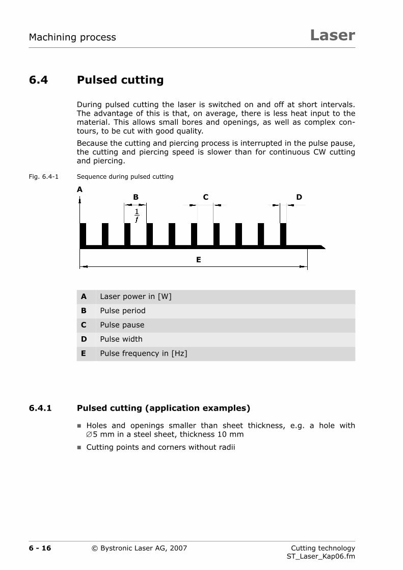
LaserMachining process
6.4 Pulsed cutting
During pulsed cutting the laser is switched on and off at short intervals.The advantage of this is that, on average, there is less heat input to thematerial. This allows small bores and openings, as well as complex con-tours, to be cut with good quality.
Because the cutting and piercing process is interrupted in the pulse pause,the cutting and piercing speed is slower than for continuous CW cuttingand piercing.
Fig. 6.4-1 Sequence during pulsed cutting
6.4.1 Pulsed cutting (application examples)
Holes and openings smaller than sheet thickness, e.g. a hole with∅5 mm in a steel sheet, thickness 10 mm
Cutting points and corners without radii
A Laser power in [W]
B Pulse period
C Pulse pause
D Pulse width
E Pulse frequency in [Hz]
B C D
E
A
6 - 16 Cutting technologyST_Laser_Kap06.fm
© Bystronic Laser AG, 2007

Laser Machining process
6.4.2 Pulsed piercing (application examples)
Piercing with lower heat input
Piercing without piercing crater
Piercing on the contour, so that inner part and outer part can be used
Tab. 6.4-1 Difference between pulsed and continuous cutting
Criterion Pulsed cutting or piercing
Continuous (CW) cut-ting
Cutting speed Low High
Heat input to the main sheet
Low High
Cut quality Rough, brown color Fine
Piercing Small, fine, as wide as cut gap
Large, with crater
6 - 17Cutting technologyST_Laser_Kap06.fm
© Bystronic Laser AG, 2007

LaserMachining process
6.4.3 Recommended values
Tab. 6.4-2 Simple guide values for pulsed piercing
Parameters Guide value
Piercing time, pulsed mode
[s] 1/2of panel width in seconds
Nozzle clearance height for pierc-ing
[mm] 1 ... 2 mm
for thinner material closer to 1 mm, for thicker closer to 2 mm
Gas pressure, pulsed piercing
[bar] 2 bar, for nozzle diameters over 2.5 mm 1 bar is also permissible
Initial pulse fre-quency, piercing
[Hz] Focal length 5.0″ 50 ... 300 Hz
Focal length 7.5″ 10 ... 25 Hz
End pulse fre-quency, piercing
[Hz] Focal length 5.0″ 150 ... 300 Hz (always higher than the initial pulse frequency)
Focal length 7.5″ 100 ... 150 Hz (always higher than the initial pulse frequency)
Pulse width [ms] Increases with sheet thickness from 1 000 ... 2 500 ms
Laser power, piercing
[W] Approximately the same or higher than normal piercing power
6 - 18 Cutting technologyST_Laser_Kap06.fm
© Bystronic Laser AG, 2007
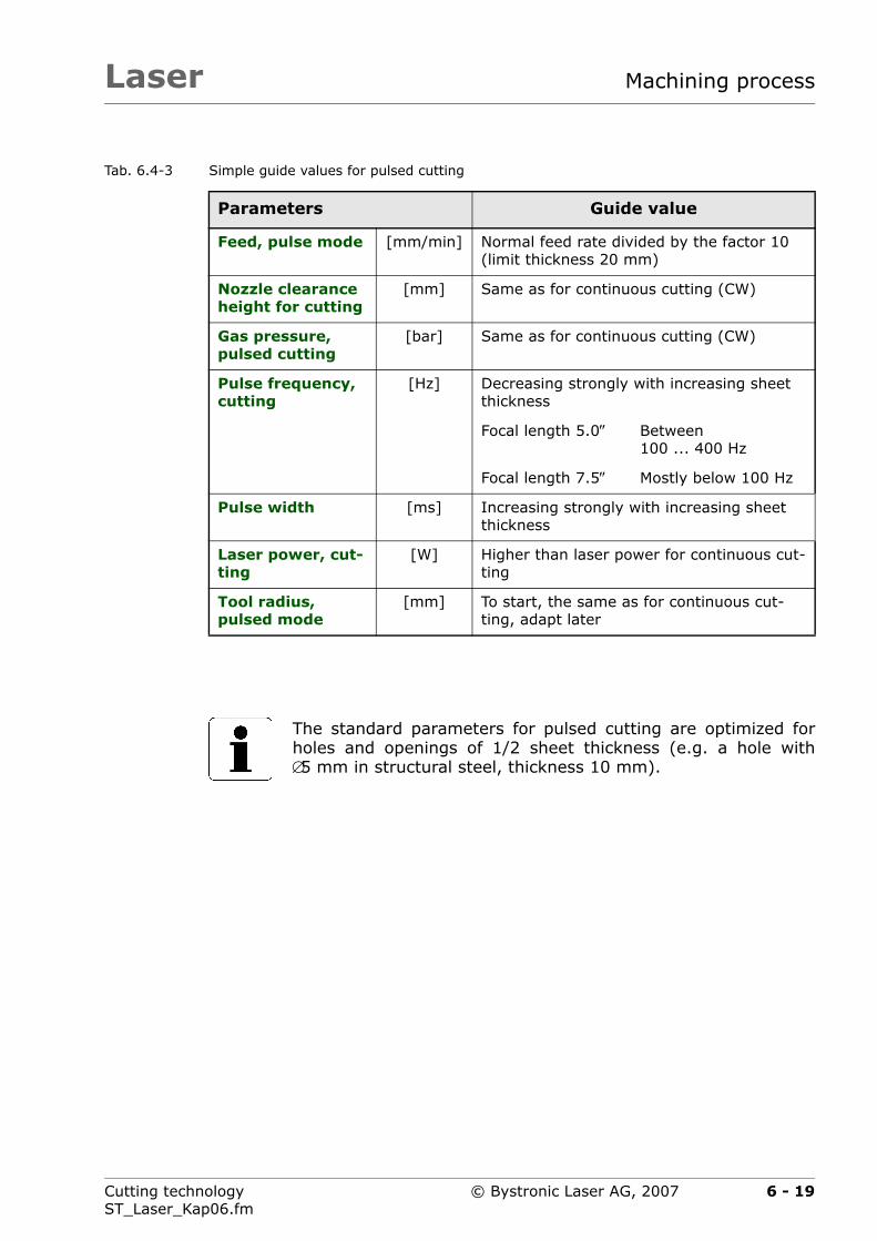
Laser Machining process
Tab. 6.4-3 Simple guide values for pulsed cutting
Parameters Guide value
Feed, pulse mode [mm/min] Normal feed rate divided by the factor 10 (limit thickness 20 mm)
Nozzle clearance height for cutting
[mm] Same as for continuous cutting (CW)
Gas pressure, pulsed cutting
[bar] Same as for continuous cutting (CW)
Pulse frequency, cutting
[Hz] Decreasing strongly with increasing sheet thickness
Focal length 5.0″ Between 100 ... 400 Hz
Focal length 7.5″ Mostly below 100 Hz
Pulse width [ms] Increasing strongly with increasing sheet thickness
Laser power, cut-ting
[W] Higher than laser power for continuous cut-ting
Tool radius, pulsed mode
[mm] To start, the same as for continuous cut-ting, adapt later
The standard parameters for pulsed cutting are optimized forholes and openings of 1/2 sheet thickness (e.g. a hole with∅5 mm in structural steel, thickness 10 mm).
6 - 19Cutting technologyST_Laser_Kap06.fm
© Bystronic Laser AG, 2007
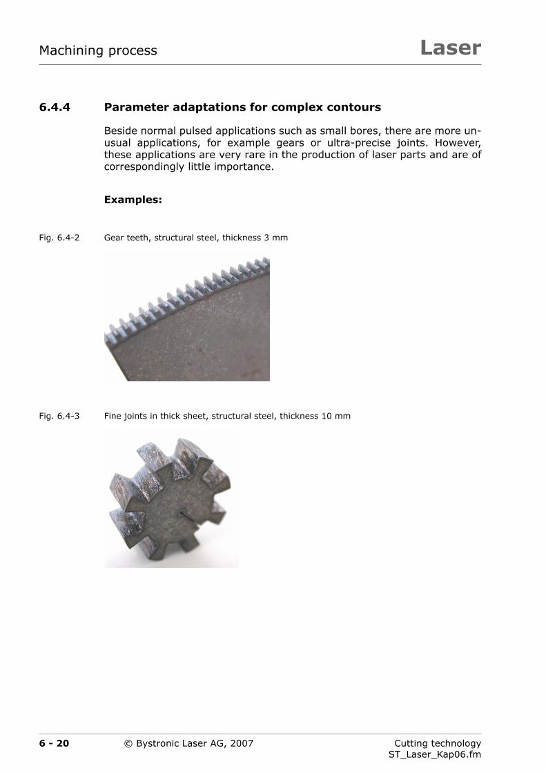
LaserMachining process
6.4.4 Parameter adaptations for complex contours
Beside normal pulsed applications such as small bores, there are more un-usual applications, for example gears or ultra-precise joints. However,these applications are very rare in the production of laser parts and are ofcorrespondingly little importance.
Examples:
Fig. 6.4-2 Gear teeth, structural steel, thickness 3 mm
Fig. 6.4-3 Fine joints in thick sheet, structural steel, thickness 10 mm
6 - 20 Cutting technologyST_Laser_Kap06.fm
© Bystronic Laser AG, 2007

Laser Machining process
6.4.4.1 Adapting the cutting mode pulse parameters
1. Reduction of feed rate
2. Reduction of pulse frequency
3. Varying the pulse width
All other parameters must need not normally be adapted.
Tab. 6.4-4 Example: Complex contour
Parameters Parameter value
Default Edited
Feed rate [mm/min] 180 45
Pulse frequency [Hz] 20 5
Pulse width [ms] 11 500 14 000
6 - 21Cutting technologyST_Laser_Kap06.fm
© Bystronic Laser AG, 2007
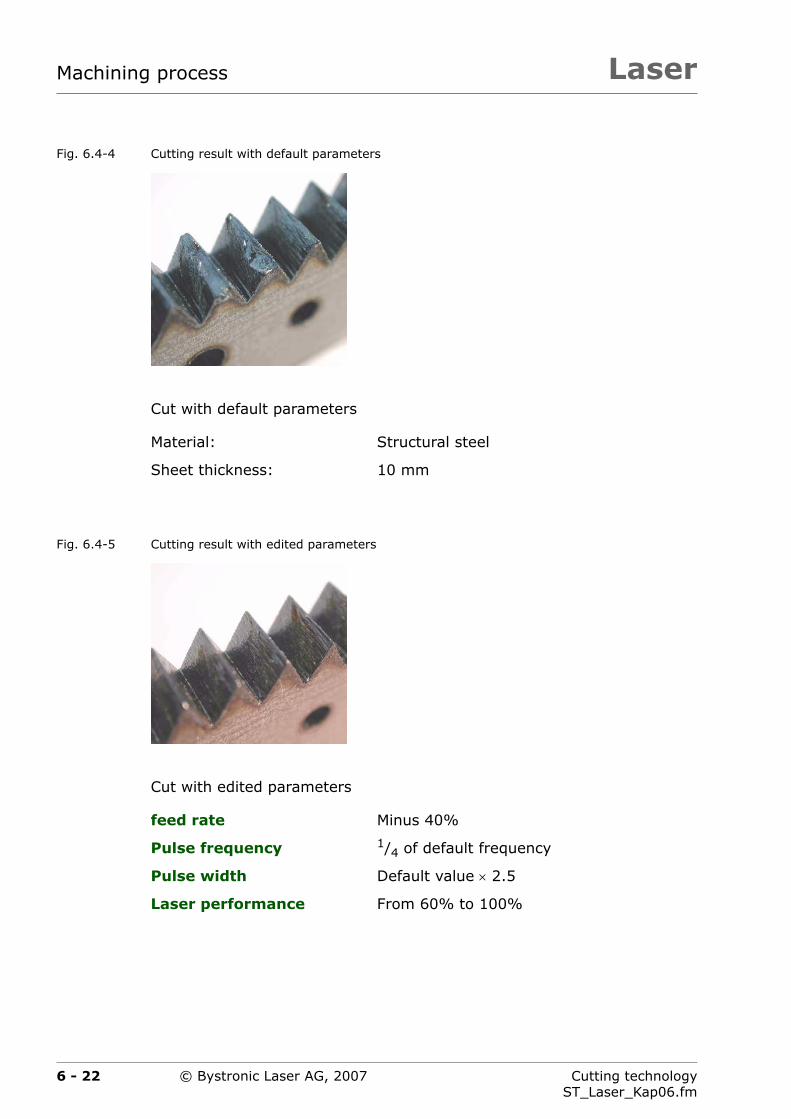
LaserMachining process
Fig. 6.4-4 Cutting result with default parameters
Cut with default parameters
Fig. 6.4-5 Cutting result with edited parameters
Cut with edited parameters
Material: Structural steel
Sheet thickness: 10 mm
feed rate Minus 40%
Pulse frequency 1/4 of default frequency
Pulse width Default value × 2.5
Laser performance From 60% to 100%
6 - 22 Cutting technologyST_Laser_Kap06.fm
© Bystronic Laser AG, 2007

Laser Machining process
6.4.4.2 Adapting the piercing mode pulse parameters
1. Increasing piercing time
2. Reducing the initial and/or final pulse frequency (reduction of heatinput)
3. In order to stop the piercing time becoming too long due to step 2,the laser power can be increased at the same time.
4. Variation of pulse width.
6.4.4.3 Influencing factors in pulsed mode
Quality and surface of main sheet
Temperature of main sheet. Pulsing (piercing and cutting) can behavedifferently with a strongly heated main sheet than a cold one.Piercing no longer takes place with individual pulses but almost like anexplosion. The edge can burn out during cutting. To keep the tempera-ture of the main sheet as low as possible, see the information in Chap-ter 6.3.1 ›Machining large sheet thickness in structural steel‹.
6.4.4.4 Alternatives to pulsed cutting
Often, cutting can be done using nitrogen instead of pulsed cutting, up tosheet thicknesses of 6 mm. See Chapter 6.3.2 ›Cutting of structural steelwith nitrogen (N2)‹.
6 - 23Cutting technologyST_Laser_Kap06.fm
© Bystronic Laser AG, 2007

LaserMachining process
6.4.4.5 Programming for pulsed contours
Whether or not contours are cut pulsed or are pierced can be determinedin two ways:
Automatically with the Technology wizard. This contains the two mostimportant rules for machine which method is used to cut contours. Italso has the advantage of shortening the programming time.
Manual. The programmer selects the individual contours based on hisown experience cutting on the machine.
If only portions of the contour are cut pulsed, e.g. the teeth in the follow-ing figures, the programming must be carried out so that there as fewchangeover points as possible (A).
Fig. 6.4-6 Poor programming (two changeover points)
Two changeover points (A)
Normal — pulse — normal
Special areas of the outer contour (e.g. gears) are not au-tomatically detected by the Technology wizard. In this casethe correct technology must be set manually.
AA
6 - 24 Cutting technologyST_Laser_Kap06.fm
© Bystronic Laser AG, 2007

Laser Machining process
Fig. 6.4-7 Good programming (one changeover point)
One changeover point
Because of the optimum positioning of the initial cut, only one changeoverpoint from normal to pulsed cutting is necessary. This improves the partquality.
Part programming has a great effect on good pulse results:
Pulsing should, where possible, be switched on after CW cutting (notthe other way round). This improves the transitions on the cut edge.
Changeover points from CW to pulse should be positioned so that thechangeover takes place at a change of direction or in a corner. Do notchangeover on straights or in curves. Changing over from one mode toanother causes a small irregularity.
A
6 - 25Cutting technologyST_Laser_Kap06.fm
© Bystronic Laser AG, 2007

LaserMachining process
Fig. 6.4-8 Cutting in CW and pulsed mode
unsuitable suitable
A Switchover point
B CW cutting
C pulsed cutting
The cutting sequence should be selected so that the complexcontours are always cut first on one part, i.e. the smallest first(usually the pulsed ones).
A
A
B
B B
BC
CA A
A
A
B
B
B B
C
C
A
A
6 - 26 Cutting technologyST_Laser_Kap06.fm
© Bystronic Laser AG, 2007

Laser Machining process
6.4.4.6 Background information
Special parameters
The modulation is switched off for pulsed cutting.
Hand-held controller
At low speeds the manual cut with display differences compared to a nor-mal pulsed cut. In manual mode only feed rates with increments of60 mm/min are considered. This means that the smallest possible feedrate is 60 mm/min, then 120 mm/min, etc.
Cut evaluation
The second half of the cut edge often displays a brownish coloring. Theoxidation, which is responsible for the brown discoloration, is generated inthe pulse pause by the oxygen cooling (see Fig. 11.2-4).
Burning
If burning occurs at the end of the cut, setting an automatic microjoint orprogramming an final cut outside the contour may help to alleviate this.
Fig. 6.4-9 Automatic microjoint or final cut
Automatic microjoints do not require programming. These can be activat-ed directly on the machine control unit. A final cut is programmed withBysoft.
A Cut direction
B Automatic microjoint
C Final cut
B
A CA A
6 - 27Cutting technologyST_Laser_Kap06.fm
© Bystronic Laser AG, 2007

LaserMachining process
6.5 Oxide-free cutting of rust and acid-resistant steel
The following points require attention when cutting rust and acid-resistantsteel.
Cutting with nitrogen to achieve oxide- and burr-free cut edges forpost-processing without with further treatment.
Employing high laser power and high pressure cutting in conjunctionwith nitrogen, comparable or even higher cutting speeds can beachieved than when cutting with oxygen depending on the sheet thick-ness.
In order to cut rust and acid-resistant steel more than 5 mm thick burr-free across the whole sheet using nitrogen, it is necessary to adjust thefocal position. By averaging out the focal position and reducing thespeed it is possible to cut clean cuts, albeit with slight burring.
With the Adaptive Optics 1 option it is not necessary to adjust the fo-cal position manually.
An oiled sheet surface improves piercing without reducing the machin-ing quality (see Fig. 11.6-2).
Whenever possible, CutControl should be employed. This increases theprocess reliability and minimizes defective parts.
Substantially greater nozzle clearance height for piercing than for cut-ting. A greater nozzle clearance height helps to prevent splashes on thelens.
When cutting rust and acid-resistant steel, support grids ofthe same material must be used.
Steel or copper grids can be used to prevent slag which formson the support points from melting into the cut part. Thesewill subsequently oxidize.
When cutting rust and acid-resistant steel on copper supportgrids, ensure that these are first cleaned with an anti-rustcleaner.
6 - 28 Cutting technologyST_Laser_Kap06.fm
© Bystronic Laser AG, 2007

Laser Machining process
6.5.1 Cutting parameters for rust and acid-resistant steel
An extremely large amount of alloyed stainless steels are available on themarket. The default parameters refer to the most common alloy (DIN1.4301).
With the appropriate adaptation of the focal position, feed rate, la-ser power and gas pressure, almost all stainless steels can be cut. Tobegin with, the respective default parameters (DIN 1.4301) should beused.
Adapt the cutting parameters based on the information given in section5.3 ›Optimization of cutting parameters‹. Compare the cutting resultsachieved with the figures in section 11 ›Cut evaluation‹.
6.5.2 Rust and acid-resistant steel with protective film
Protective films are adhered to the surface to protect brushed, polished orrefined surfaces with sheet thicknesses of up to 3 mm.
Important for a decisive role for laser cutting is how well the film adheresto the surface. Poorly adhered films come lose from the main sheet due tothe pressure of the cutting gas, thus interrupting the cutting process.
Tab. 6.5-1 Cutting main sheets with protective films
Protective film status Measures
Protective film has poor ad-hesion
Remove the protective film and cut with the cut-ting parameters for rust and acid-resistant steel.
The surface is however no longer protected.
Vaporize the protective film on the initial cut or whole contour.
The programming takes place in Bywork under post processor 2. Select process macro 5 for the vaporization of the protective film.
The necessary cutting parameters are saved on the laser cutting machine.
Protective film has good ad-hesion
Directly cut the main sheet with special cutting parameters (Add-on = plastic-film).
This is the quickest, most economical solution.
6 - 29Cutting technologyST_Laser_Kap06.fm
© Bystronic Laser AG, 2007
LaserMachining process
Recommended protective films:
Laserguard 3100H5 and Laserquard 3100H3 Light produced by Nitto Den-ko with the following properties good for laser cutting:
Very good adhesion during cutting. No need to vaporize protective filmbeforehand.
Visually cleanly cut parts without black discoloration around edges.
No fraying of protective film around edges.
High tear strength when removing from sheet (especially after bendingprocess)1)
Minimal residual adhesive on the sheet
The adhesive force of the protective film lessens over time.Do not store main sheets with protective films for longer peri-ods of time.
Do not store main sheets with special protective films forlonger periods of time.
1) This is a very important property. Approx. 80% of parts cut with a laser are bent afterwards.
6 - 30 Cutting technologyST_Laser_Kap06.fm
© Bystronic Laser AG, 2007

Laser Machining process
6.6 Oxide-free cutting of aluminum alloys
An extremely large amount of aluminum alloys are available on the mar-ket. The default parameters refer to the most common alloy (DIN3.3535), AlMg3. This alloy can also be bent well.
The cutting gas used is nitrogen (N2). Oxygen is also used for piercingin thick sheets.
With the appropriate adaptation of the focal position, feed rate, la-ser power and gas pressure, almost all aluminum alloys can be cut.To optimize the cutting parameters, first the default parameters arestarted and the specific parameters are adapted.
Adapt the cutting parameters based on the information given in section5.3 ›Optimization of cutting parameters‹. Compare the cutting resultsachieved with the figures in section 11 ›Cut evaluation‹.
Aluminum is a highly reflective material. If the laser beam is no longercutting the sheet, the laser power will be reflected. This can shorten thelife of the optics. It is recommended to monitor the production processwhen cutting aluminum and its alloys.
The softer and purer an aluminum alloy is, the more difficult it is to cutwith laser. This can be recognized by the burrs on sheets under 3 mmthick. In addition, the feed rate must be reduced by up to 40%, e.g. forpure aluminum (Al 99.5%).
6 - 31Cutting technologyST_Laser_Kap06.fm
© Bystronic Laser AG, 2007

LaserMachining process
6.7 Machining diverse materials
Material Comments
Titanium The cutting gases nitrogen or argon are employed for cutting panels from titanium. The cutting parameter database contains the parameters for titanium.
When cutting with nitrogen the cut edge oxidizes and takes on a brown color. In addition, a burr forms on the underside of the sheet (see Fig. 11.3-29).
When using argon, an oxide-free, clean cut edge without burrs is produced (see Fig. 11.4-1).
Copper
Brass
Both materials possess high reflectance and high thermal conductivity.
Brass can be cut with nitrogen up to a thickness of 6 mm, depending on the laser used (also Fig. 11.3-26 and Fig. 11.3-27).
Copper can be cut up to a sheet thickness of 3 mm; oxygen must be used as the cutting gas.
Brass and copper in particular are very soft materials. The underside therefore generally has burrs.
It is not economical to cut large amounts of copper on a laser cutting machine. Water jet cutting is more suitable.
Copper and brass may only be cut if a suitable device for ab-sorbing reflections is installed on the laser cutting machine.Reflections can otherwise damage the optical elements.
6 - 32 Cutting technologyST_Laser_Kap06.fm
© Bystronic Laser AG, 2007

Laser Machining process
Material Comments
Hardox, Weldox, Domex
These materials can generally be cut to good quality. The structural steel default parameters can be used.
Austenitic manga-nese steel
Can be cut in sheets up to approx. 10 mm thick, but causes a lot of smoke. It can also be cut with nitrogen to reduce smoke development.
Tantalum, nickel-sil-ver, Inconel
These materials can be cut with Nitrogen. The rust and acid-resistant steel default parameters can be used.
The maximum cuttable thickness is usually less than the maximum cuttable thickness of rust and acid-re-sistant steel.
Checker plate Can be easily cut. Checkers always down and adapt the cutting parameters to maximum thickness.
Pure aluminum Is poorly suited to laser cutting because of the high reflectance. The aluminum default parameters can be used.
The maximum cuttable thickness is usually 2 ... 4 mm less than the maximum cuttable thickness of AlMg3. The cutting speed must be reduced by up to 40%.
Plastics Plastics must not be cut on the laser cutting machine.
Observe safety instructions!
WARNINGToxic vapors
The fumes given off on combustion are highly toxic.They cannot be completely removed by the extractionsystem.
Plastics must not be cut on the laser cutting machine.
6 - 33Cutting technologyST_Laser_Kap06.fm
© Bystronic Laser AG, 2007

LaserMachining process
Material Comments
Wood, leather, card-board, paper
Organic materials must not be cut on the laser cutting machine.
The filters on the dust extraction unit are not suited to this purpose and may be damaged. (see manufactur-er's operating manual).
Observe safety instructions!
WARNINGFire risk
Cutting organic material presents a fire hazard.
Organic materials must not be cut on the laser cuttingmachine.
Material Comments
Silver Pure silver or silver-plated sheets may not be cut. The reflectance is too great. This can damage the optical elements.
Ceramics, tiles, glass
Ceramics or brittle materials are not suitable for cut-ting with laser. The heat input bursts the material.
Other materials Information on other materials can be obtained from the manufacturer's customer service department.
6 - 34 Cutting technologyST_Laser_Kap06.fm
© Bystronic Laser AG, 2007

Laser Machining process
6.8 Plasma cut
Whenever a very bright, white-blue light is visible during cutting, it isknown as a plasma cut.
Fig. 6.8-1 Plasma cut in structural steel, 1 mm thick
Fig. 6.8-2 Plasma cut in stainless steel, 20 mm thick
The advantage of the plasma cut is the increased cutting speed of up to50%.
The plasma cut is only possible at high laser power above 4 400 W.
The plasma cut is generated during laser cutting solely by editing thecutting parameters. The cutting gas employed is nitrogen.
The plasma cut can be used on very thin sheets up to 2 mm thick andon rust and acid-resistant steel of 15 ... 25 mm.
The roughness of the cut surface for a plasma cut is significantly great-er than with a quality cut (see Fig. 3.3-3).
CutControl does not function for the plasma cut and is automatically de-activated by the cutting parameters.
In laser cutting, the so-called plasma cut should not be confused withthe plasma cutting method.
6 - 35Cutting technologyST_Laser_Kap06.fm
© Bystronic Laser AG, 2007

LaserMachining process
The following cutting parameters are different for the plasma cut, com-pared to the normal cut.
Tab. 6.8-1 Cutting parameters for plasma cut compared to normal cut
6.8.1 Practical applications
The operator decides whether to use the normal cut or the plasma cut.
The very high cutting speeds used in the plasma cut in sheets up to 2 mmthick can only be properly utilized on Byspeed machines.
On Bystar machines, the cutting speed cannot be achieved on parts small-er than 500 × 500 mm. The acceleration is too small. No parameters havetherefore been saved for plasma cutting in sheets less than 1.5 mm thick.
Parameters Structural steel
0.8 ... 2 mma) thick
a) Varies according to laser source in use
Rust and acid-resis-tant steel
15 ... 25 mma) thick
Feed rate Much higher (30 ... 50%) Much higher (20 ... 40%)
Laser perfor-mance
Higher (20 ... 40%) ⎯
Nozzle clearance height for cutting
Higher (1.5 ... 2 mm in-stead of 0.7 mm)
⎯
Nozzle type H-nozzle instead of HK-noz-zle
⎯
Nozzle diameter Greater (HK17/20 instead of HK15)
⎯
Gas pressure Lower (20 ... 40%) ⎯
Focal position Same or slightly lower (0 ... 2 mm)
Much higher, to approx. 60% in main sheet
CutControl Deactivated Deactivated
6 - 36 Cutting technologyST_Laser_Kap06.fm
© Bystronic Laser AG, 2007

Laser Machining process
6.8.2 Cutting parameters for custom sheets
The plasma cut can also be used with:
Rust and acid-resistant steel 0.8 mm thick with protective film
Electroplated steel plate, 0.75 mm thick,
etc.
The cutting parameters for these custom sheets must be determined bythe operator.
Cutting parameters for custom sheets can be most quickly determined ifthe stored default parameters for the plasma cut are used as the basis.
Example:
For electroplated steel plate 0.75 mm thick, the cutting parameters forstructural steel 1 mm thick are used to start, (e.g. 10332r10.z5n). After-wards, optimize the parameters: feed rate, laser power, gas pressureand focal position, etc.
Fig. 6.8-3 Example of cut edges, cut with laser source 5 200 W
Plasma cut in rust and acid-resistant steel, 20 mm thick
Cutting gas nitrogen N2
Feed rate 0.45 m/min
Gas pressure 15 bar
Focal position approx.12 mm in sheet
6 - 37Cutting technologyST_Laser_Kap06.fm
© Bystronic Laser AG, 2007
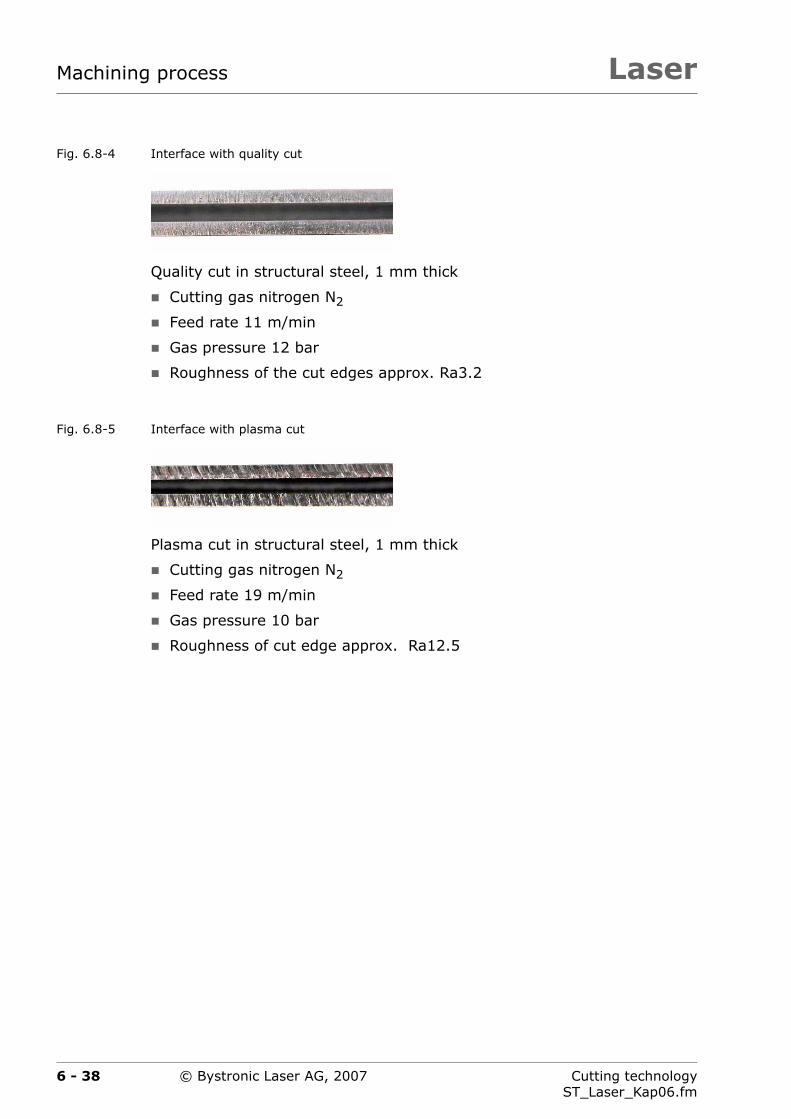
LaserMachining process
Fig. 6.8-4 Interface with quality cut
Quality cut in structural steel, 1 mm thick
Cutting gas nitrogen N2
Feed rate 11 m/min
Gas pressure 12 bar
Roughness of the cut edges approx. Ra3.2
Fig. 6.8-5 Interface with plasma cut
Plasma cut in structural steel, 1 mm thick
Cutting gas nitrogen N2
Feed rate 19 m/min
Gas pressure 10 bar
Roughness of cut edge approx. Ra12.5
6 - 38 Cutting technologyST_Laser_Kap06.fm
© Bystronic Laser AG, 2007

Laser Machining process
6.8.3 Plasma initial cut type in rust and acid-resistant steel, 15/20 mm thick
In principal, the Bysoft Technology wizard selects the correct technologyfor each laser type.
When plasma cutting it is important that the initial cut type is correctly se-lected (especially for rust- and acid-resistant steel, 15 /20 mm).
Tab. 6.8-2 Initial cut in rust- and acid-resistant steel, 15 / 20 mm thick, for laser source 5 200 W
The initial cut types differ according to sheet thickness and la-ser power.
Lead-in Comments
Example:
Rust and acid-resistant steel
Thickness 15 mm
Laser source 5 200 W
Initial cut type Straight line at right angles on the contour. This is selected automatically by the technology wizard.
Example:
Rust and acid-resistant steel
Thickness 20 mm
Laser source 5 200 W
The Technology wizard automatically selects the initial cut type Straight line with arc on the contour
6 - 39Cutting technologyST_Laser_Kap06.fm
© Bystronic Laser AG, 2007

LaserMachining process
6.8.3.1 Partial plasma cut for sheet thicknesses up to 2 mm
It is possible to change between normal and plasma cut a number of timeswithin one part. This allows the part time to be minimized and the qualityto be partially improved.
Fig. 6.8-6 Partial plasma cut
It is possible to program into Bysoft how to cut which part sections. Inthe example in Fig. 6.8-6, the two long straights (A) can be cut with theplasma cut (CW).
All other sections, including the inner contour, are cut with the quality cut(process macro 1). These optimizations are worthwhile for high part num-bers in particular.
A
A
6 - 40 Cutting technologyST_Laser_Kap06.fm
© Bystronic Laser AG, 2007

Laser Machining process
6.8.4 Time comparison between quality and plasma cut
Steel disk, 1 mm thick, cutting gas Nitrogen N2 with laser source 5 200 W
Fig. 6.8-7 Structural steel disk, 1 mm thick
Cutting times:
Reduction in cutting time of more than 40% using the plasma cut
Normal cut:
Feed rate = 11 m/min
Cutting time = 26 s
Plasma cut:
Feed rate = 19 m/min
Cutting time = 15 s
Use of the plasma cut in the thin sheet range up to 1.5 mm isworthwhile primarily for large contours with few changes in di-rection.
∅480 mm
∅100 mm
6 - 41Cutting technologyST_Laser_Kap06.fm
© Bystronic Laser AG, 2007
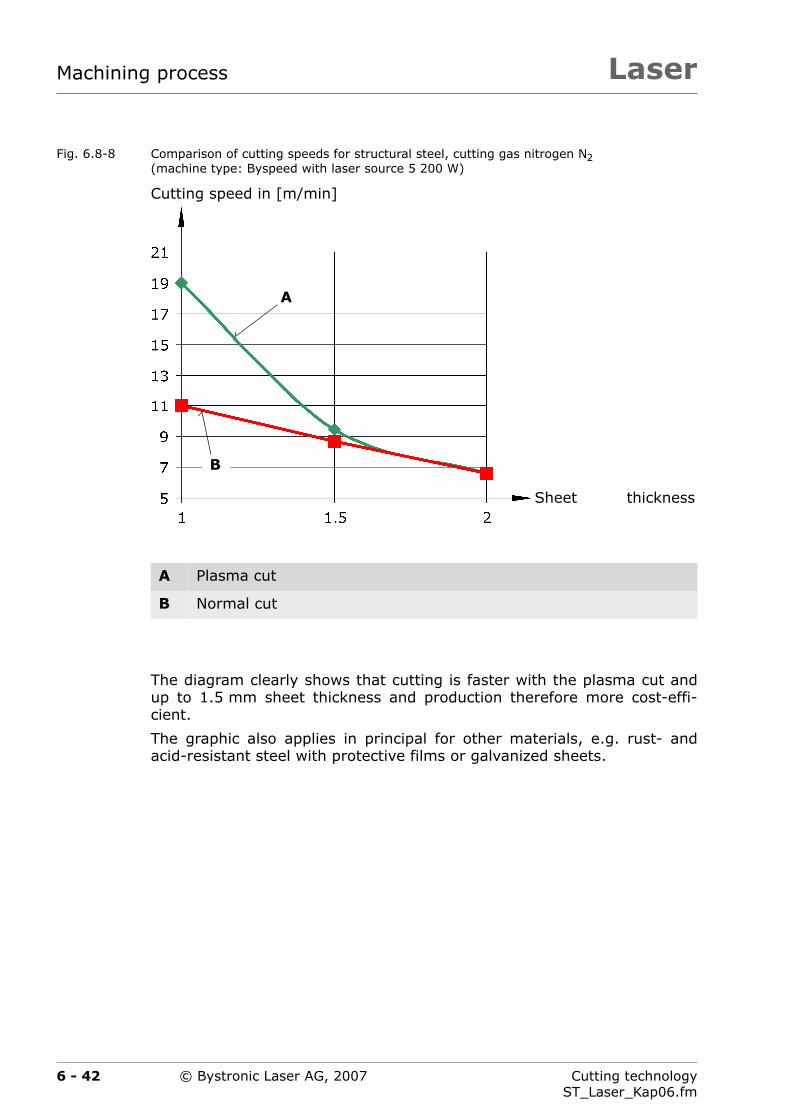
LaserMachining process
Fig. 6.8-8 Comparison of cutting speeds for structural steel, cutting gas nitrogen N2(machine type: Byspeed with laser source 5 200 W)
The diagram clearly shows that cutting is faster with the plasma cut andup to 1.5 mm sheet thickness and production therefore more cost-effi-cient.
The graphic also applies in principal for other materials, e.g. rust- andacid-resistant steel with protective films or galvanized sheets.
A Plasma cut
B Normal cut
A
Cutting speed in [m/min]
Sheet thickness
B
6 - 42 Cutting technologyST_Laser_Kap06.fm
© Bystronic Laser AG, 2007

Laser Machining process
6.9 Engraving
6.9.1 General
Engraving is available as standard on every machine and can be used forthe following tasks:
labeling parts
engraving positions (crosses for drill holes)
engraving fold edges
applying visual elements and labels
pre-positioning of sheets or parts
Fig. 6.9-1 Engraving example
Engraving is chiefly used on rust and acid-resistant steel and structuralsteel.
It is possible to engrave with nitrogen or oxygen. The same gas should beused for engraving as for cutting to avoid the loss of time for purging.
The cutting parameters contain the engraving data. Engraving is easy toprogram in Bysoft.
Engraving for angle measurements
Cutting gas oxygen O2
Engraving as inscription
Cutting gas nitrogen N2
6 - 43Cutting technologyST_Laser_Kap06.fm
© Bystronic Laser AG, 2007

LaserMachining process
Highly reflective materials such as copper, brass or shinysurfaces are not suitable for engraving. The engraving canbe weak or may not appear at all.
With strongly-reflective surfaces, do not select an Engrav-ing laser power higher than 2 000 W. The parameter En-graving factor must not be greater than 5. Otherwise, thereflected laser output can cause damage to the laser cut-ting machine.
Engraved contours or lettering should not have a minimumdepth of less than 8 mm. This ensures good legibility.
6 - 44 Cutting technologyST_Laser_Kap06.fm
© Bystronic Laser AG, 2007
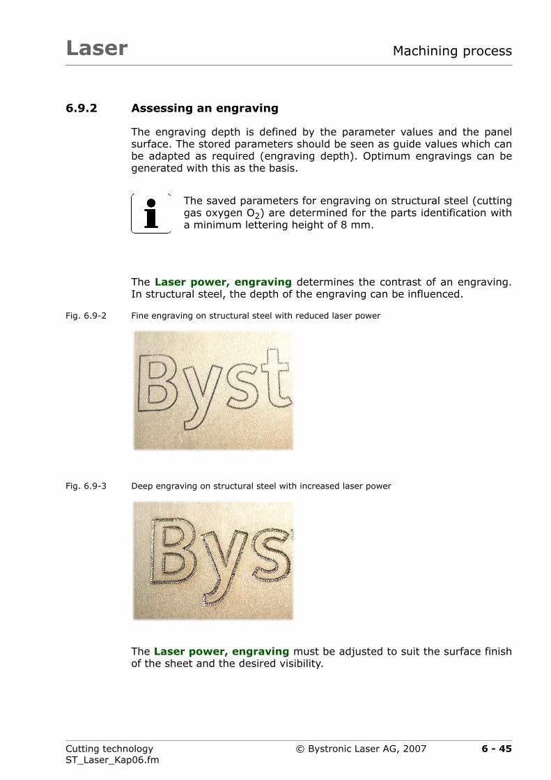
Laser Machining process
6.9.2 Assessing an engraving
The engraving depth is defined by the parameter values and the panelsurface. The stored parameters should be seen as guide values which canbe adapted as required (engraving depth). Optimum engravings can begenerated with this as the basis.
The Laser power, engraving determines the contrast of an engraving.In structural steel, the depth of the engraving can be influenced.
Fig. 6.9-2 Fine engraving on structural steel with reduced laser power
Fig. 6.9-3 Deep engraving on structural steel with increased laser power
The Laser power, engraving must be adjusted to suit the surface finishof the sheet and the desired visibility.
The saved parameters for engraving on structural steel (cuttinggas oxygen O2) are determined for the parts identification witha minimum lettering height of 8 mm.
6 - 45Cutting technologyST_Laser_Kap06.fm
© Bystronic Laser AG, 2007

LaserMachining process
6.10 Machining with process macros
Processing with process macros provides additional parameters to assistoptimum cutting of complex contours.
Programming is carried out in Bysoft. The cutting parameters must be al-tered on the laser cutting machine. Five process macros are available (seeTab. 6.10-1).
Fig. 6.10-1 Example with process macros
A Small contour (hole) with process macro 1
B Initial cut with process macro 2
B
A
6 - 46 Cutting technologyST_Laser_Kap06.fm
© Bystronic Laser AG, 2007

Laser Machining process
Tab. 6.10-1 Process macros available
Process macro Usage
1 Process macro 1 is automatically opened by the Bysoft Technology wizard according to the rules for small con-tours based on Tab. 4.2-3 and Tab. 4.2-4. The cutting parameters are also determined for the small contours (e.g. the small hole in Fig. 6.10-1).
2 For initial cut for moving into thick main sheets
For cutting on thin sheets with scanning (see Chapter 8.2.6 ›Thin sheet machining using scanning‹).
3 Available for customer-specific applications.
4 Available for customer-specific applications.
5 Vaporization of protective films on main sheets made of rust and acid-resistant steel.
6 - 47Cutting technologyST_Laser_Kap06.fm
© Bystronic Laser AG, 2007

LaserMachining process
6.10.1 Process macro 2 for the initial cut
Starting on the first geometry element of the initial cut (A) using the cut-ting parameters in process macro 2 substantially improves process reli-ability.
Fig. 6.10-2 Starting on the first geometry element
Starting with process macro 2 is mostly used on thick sheets:The Bysoft Technology wizard automatically selects the processmacro 2 for the initial cut.
A
6 - 48 Cutting technologyST_Laser_Kap06.fm
© Bystronic Laser AG, 2007
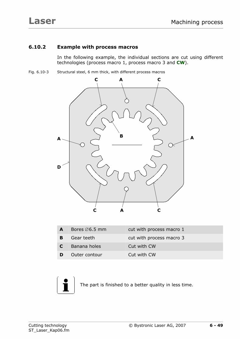
Laser Machining process
6.10.2 Example with process macros
In the following example, the individual sections are cut using differenttechnologies (process macro 1, process macro 3 and CW).
Fig. 6.10-3 Structural steel, 6 mm thick, with different process macros
A Bores ∅6.5 mm cut with process macro 1
B Gear teeth cut with process macro 3
C Banana holes Cut with CW
D Outer contour Cut with CW
The part is finished to a better quality in less time.
A
A A
A
B
C
D
C C
C
6 - 49Cutting technologyST_Laser_Kap06.fm
© Bystronic Laser AG, 2007

LaserMachining process
6.11 Piercing method
Correct piercing is very important for the subsequent cutting process.There are therefore various piercing methods.
Tab. 6.11-1 Process reliability and piercing time
Piercing method Process safety
Piercing time
Conventional, pulsed piercing without monitoring
Very high Very long
CPP
Controlled Pulsed Piercing
Very high Short
Normal CW piercing High Short
Pre-piercing CW High Short
Pre-piercing CPP Very high Medium
The Bysoft Technology wizard selects the piercing method au-tomatically. Manual adjustments can be made for special appli-cations. See chapter 6.3.1.1 ›piercing‹
6 - 50 Cutting technologyST_Laser_Kap06.fm
© Bystronic Laser AG, 2007

Laser Machining process
6.11.1 Conventional, pulsed piercing (without monitoring)
This piercing method is only used with laser source 2 200 W and 3 000 W(or when required).
Applications: Small bores
Piercing directly on the contour. Allows the innerand outer parts to be used.
Advantage: small piercing hole
Disadvantage: Time-consuming piercing (with CPP, the piercingtime, pulsed mode is greatly reduced)
With conventional pulsed piercings, the sheet thickness in [mm]corresponds approximately to the piercing time in seconds.Using CPP (Controlled Pulsed Piercing), the piercing time forsheet thicknesses up to 15 mm is substantially lower.
6 - 51Cutting technologyST_Laser_Kap06.fm
© Bystronic Laser AG, 2007
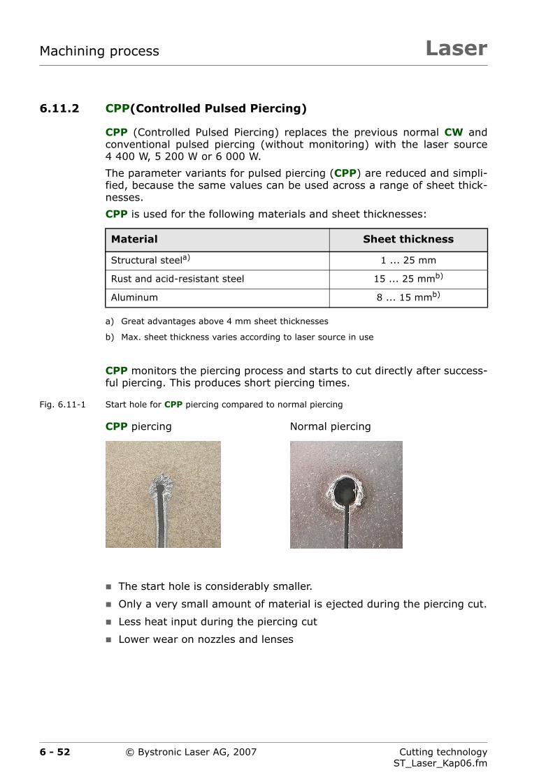
LaserMachining process
6.11.2 CPP(Controlled Pulsed Piercing)
CPP (Controlled Pulsed Piercing) replaces the previous normal CW andconventional pulsed piercing (without monitoring) with the laser source4 400 W, 5 200 W or 6 000 W.
The parameter variants for pulsed piercing (CPP) are reduced and simpli-fied, because the same values can be used across a range of sheet thick-nesses.
CPP is used for the following materials and sheet thicknesses:
CPP monitors the piercing process and starts to cut directly after success-ful piercing. This produces short piercing times.
Fig. 6.11-1 Start hole for CPP piercing compared to normal piercing
The start hole is considerably smaller.
Only a very small amount of material is ejected during the piercing cut.
Less heat input during the piercing cut
Lower wear on nozzles and lenses
Material Sheet thickness
Structural steela)
a) Great advantages above 4 mm sheet thicknesses
1 ... 25 mm
Rust and acid-resistant steel 15 ... 25 mmb)
b) Max. sheet thickness varies according to laser source in use
Aluminum 8 ... 15 mmb)
CPP piercing Normal piercing
6 - 52 Cutting technologyST_Laser_Kap06.fm
© Bystronic Laser AG, 2007
Laser Machining process
The parameters for CPP piercing are determined for mate-rials as set out in Chapter 3.2 ›Material specification‹. TheCPP settings must be modified for different materials.
CutControl must be activated (check Setup machine andParameter values ).
All pierces executed using CPP must be programmed aspulse pierces. If the laser source is correctly selected, theBysoft Technology wizard automatically selects pulsedpiercing (only with laser source 4 400 W, 5 200 W and6 000 W).
6 - 53Cutting technologyST_Laser_Kap06.fm
© Bystronic Laser AG, 2007

LaserMachining process
6.11.2.1 Sequence for a CPP piercing
CPP piercing is carried out in two steps. Step 1 prepares the penetration,step 2 completes it.
First step
The starting point for CPP piercing is located approx. 8 mm above themain sheet. The first step of CPP piercing begins from this position (with-out delay).
Fig. 6.11-2 First step for CPP piercing
A Lens
B Nozzle
A
B
8m
m
6 - 54 Cutting technologyST_Laser_Kap06.fm
© Bystronic Laser AG, 2007

Laser Machining process
Second step
CutControl monitors the piercing cut to check when it has penetrated rightthrough the material. Once the main sheet is pierced, the laser cuttingmachine immediately starts to cut.
Fig. 6.11-3 Second step for CPP piercing
If the piercing is too large and the material overheats, the values of thefollowing piercing parameters must be reduced:
Focal position
Pulse width, step 2
Piercing pressure, Gas type 1, step 2
A Lens
B Nozzle
C Mirror
D CutControl
A
B
0,6
...
2m
m
DC
6 - 55Cutting technologyST_Laser_Kap06.fm
© Bystronic Laser AG, 2007
LaserMachining process
6.11.3 Normal CW piercing
This piercing method is the most common. Especially for fusion cutting us-ing Nitrogen N2 in structural steel, rust-and acid-resistant steel and alumi-num.
6.11.4 Pre-piercing CW
Pre-piercing is used with laser sources 2 200 W and 3 000 W.
Application:
Parts with numerous bores and openings, or small parts tightly nested.
Procedure:
1. Cutting plan in Bywork with precutting functions. You can choose toprecut one part or the entire cutting plan in each case. Normally onlyone part is precut.
2. Pre-piercing
3. Remove piercing splashes from panel (only after pre-piercing entirecutting plan).
4. Leave sheet to cool if necessary.
5. Cutting
Advantage: rapid piercing
Disadvantage: Causes a relatively large start hole
6 - 56 Cutting technologyST_Laser_Kap06.fm
© Bystronic Laser AG, 2007
Laser Machining process
Solution:
Reduce size of cutting area by dividing a large cutting plan (e.g. 1 × 2 m)in two smaller ones (e.g. 1 × 1 m).
Because of the thermal expansion, single parts should only be cut in mul-tiple cuts for no-tolerance parts.
Use a smaller nozzle for pre-piercing than for cutting. (e.g.HK12 instead of HK17). The gas pressure during piercing mustbe doubled in order to prevent splashes on the lens. The heatinput to the main sheet is reduced considerably by pre-piercing.The piercing hole is smaller.
Once all holes are pre-cut, the axes automatically travel to theorigin. The nozzle can be easily replaced here.
The piercing gas pressurecan be reset to the original valueand the piercing time reduced to 0.
Using this procedure it is possible to cut holes and openings ofsizes 0.8 ... 1.0 × sheet thickness in normal thicknesses with-out pulsing.
If the sheet heats strongly during cutting, it expands. Thiscan cause the pre-cut holes to be displaced.
6 - 57Cutting technologyST_Laser_Kap06.fm
© Bystronic Laser AG, 2007
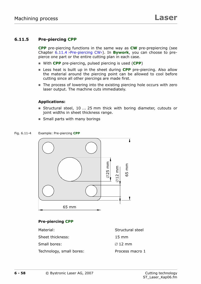
LaserMachining process
6.11.5 Pre-piercing CPP
CPP pre-piercing functions in the same way as CW pre-prepiercing (seeChapter 6.11.4 ›Pre-piercing CW‹). In Bywork, you can choose to pre-pierce one part or the entire cutting plan in each case.
With CPP pre-piercing, pulsed piercing is used (CPP)
Less heat is built up in the sheet during CPP pre-piercing. Also allowthe material around the piercing point can be allowed to cool beforecutting since all other piercings are made first.
The process of lowering into the existing piercing hole occurs with zerolaser output. The machine cuts immediately.
Applications:
Structural steel, 10 ... 25 mm thick with boring diameter, cutouts orjoint widths in sheet thickness range.
Small parts with many borings
Fig. 6.11-4 Example: Pre-piercing CPP
Pre-piercing CPP
Material: Structural steel
Sheet thickness: 15 mm
Small bores: ∅ 12 mm
Technology, small bores: Process macro 1
∅25
mm
∅12
mm
65
mm
65 mm
6 - 58 Cutting technologyST_Laser_Kap06.fm
© Bystronic Laser AG, 2007

Laser Machining process
6.12 Microjoints
Microjoints or weld points prevent parts from tilting up or dropping down-thus increasing process safety.
Tab. 6.12-1 Application overview
Microjoint Usage Benefits
Automatic micro-joints
Structural steelthickness 1 ... 10 mm
Rust and acid-resistant steelthickness 1 ... 10 mm
AluminumThickness ... 10mm
The easiest and quickest way of preventing parts from tipping over or falling down
The automatic microjoint is activated on the laser cut-ting machine.
Several pro-grammed micro-joints
Structural steelthickness 1 ... 10 mm
Rust and acid-resistant steelthickness 1 ... 10 mm
AluminumThickness 1 ... 10mm
Increased safety, e.g. in low-staffed production combined with automation
Weld points Structural steelthickness 4 ... 15 mm
Simple breaking out of cut parts
Cutting of inner parts
Highly dynamic cutting all materials up to 3 mm thick
The inner parts do not need breaking out.
6 - 59Cutting technologyST_Laser_Kap06.fm
© Bystronic Laser AG, 2007

LaserMachining process
A cutout is cut to completion without microjoints. I.e. when the cut iscompleted the laser beam joins the start of the cut gap again. However,separation of the material occurs before the geometric end of the cut by atleast the width of the cutting gap (D).
Fig. 6.12-1 Part cut-out microjoint
The cut out part begins to tilt just at this moment and the laser beammeets it laterally and causes a burn. The laser beam is reflected in themelt of this burn and thus causes a further burn in the cut-out.
If these burns are to be prevented, microjoints can be employed. The CNCcontrols have an automatic microjoint function.
A Laser beam at separation
B Lead-in
C Laser beam at start and end of cut
D cutting gap width
D
BA C
6 - 60 Cutting technologyST_Laser_Kap06.fm
© Bystronic Laser AG, 2007
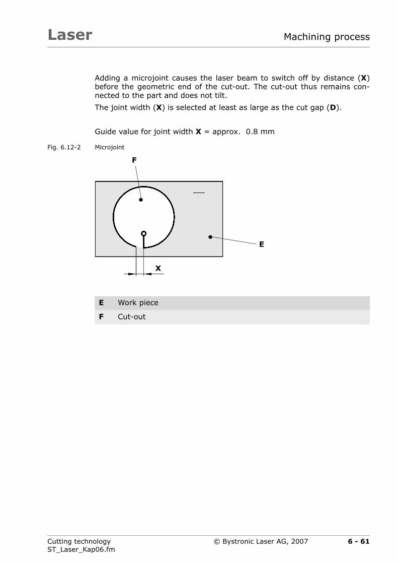
Laser Machining process
Adding a microjoint causes the laser beam to switch off by distance (X)before the geometric end of the cut-out. The cut-out thus remains con-nected to the part and does not tilt.
The joint width (X) is selected at least as large as the cut gap (D).
Guide value for joint width X = approx. 0.8 mm
Fig. 6.12-2 Microjoint
E Work piece
F Cut-out
X
E
F
6 - 61Cutting technologyST_Laser_Kap06.fm
© Bystronic Laser AG, 2007

LaserMachining process
6.12.1 Set microjoints
Microjoints can be applied in two ways:
Fig. 6.12-3 Automatically set / programmed microjoints
Automatic
The machine does not cut the edges completely, a joint is created foreach initial cut (A). This function is activated on the laser cutting ma-chine.
Programmed
In addition to the automatically defined microjoints, further microjointscan be programmed with Bysoft (B).
To facilitate easy break-out of the parts, two microjoints on one axis areexpedient.
A Automatically set microjoint
B Programmed microjoint
C Axis or breaking out of part
Automatic and programmed microjoints can be used in combi-nation. These can be selected on the machine control unit.
A
B
C
6 - 62 Cutting technologyST_Laser_Kap06.fm
© Bystronic Laser AG, 2007
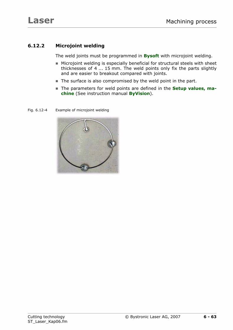
Laser Machining process
6.12.2 Microjoint welding
The weld joints must be programmed in Bysoft with microjoint welding.
Microjoint welding is especially beneficial for structural steels with sheetthicknesses of 4 ... 15 mm. The weld points only fix the parts slightlyand are easier to breakout compared with joints.
The surface is also compromised by the weld point in the part.
The parameters for weld points are defined in the Setup values, ma-chine (See instruction manual ByVision).
Fig. 6.12-4 Example of microjoint welding
6 - 63Cutting technologyST_Laser_Kap06.fm
© Bystronic Laser AG, 2007

LaserMachining process
6.12.3 Alternatives to microjoints
Instead of microjoints, the inner parts can also be cut. This is especiallyused for sheet thicknesses up to 3 mm. Bysoft provides simple aids. Thisoffers the advantage that manual breaking-out is not required.
Fig. 6.12-5 Cut inner part
A Inside
B Guide cuts for cutting the inner part
If microjoints are employed the initial cut type straight per-pendicular must be used.Further details on microjoints can be found in the Operatinginstructions.
A
B
6 - 64 Cutting technologyST_Laser_Kap06.fm
© Bystronic Laser AG, 2007

Laser Machining process
6.13 Machining corners
6.13.1 Machining corners with corner tolerance
If a pointed corner is also required on the outer contour for further ma-chining, it must be programmed without a rounding radius.
Tab. 6.13-1 Corner tolerance
Too large Correct
If the corner tolerance is too high, overshooting can occur onthe workpiece.
6 - 65Cutting technologyST_Laser_Kap06.fm
© Bystronic Laser AG, 2007
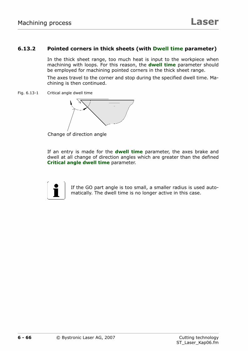
LaserMachining process
6.13.2 Pointed corners in thick sheets (with Dwell time parameter)
In the thick sheet range, too much heat is input to the workpiece whenmachining with loops. For this reason, the dwell time parameter shouldbe employed for machining pointed corners in the thick sheet range.
The axes travel to the corner and stop during the specified dwell time. Ma-chining is then continued.
Fig. 6.13-1 Critical angle dwell time
If an entry is made for the dwell time parameter, the axes brake anddwell at all change of direction angles which are greater than the definedCritical angle dwell time parameter.
If the GO part angle is too small, a smaller radius is used auto-matically. The dwell time is no longer active in this case.
Change of direction angle
6 - 66 Cutting technologyST_Laser_Kap06.fm
© Bystronic Laser AG, 2007
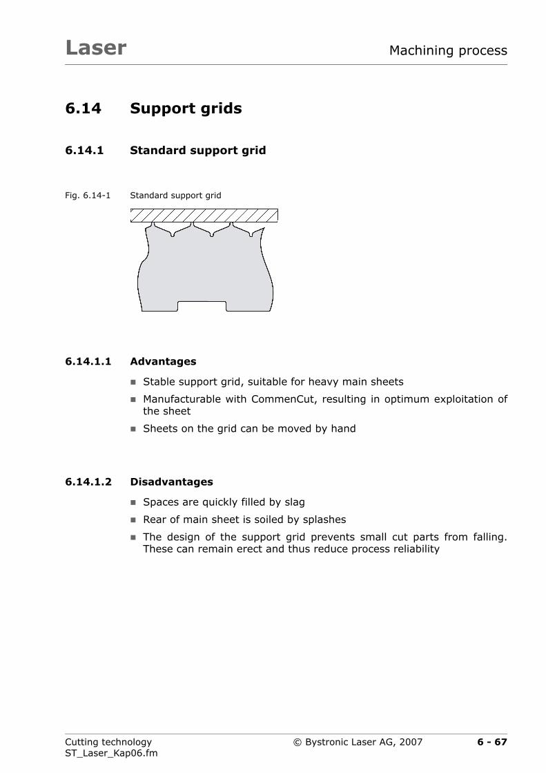
Laser Machining process
6.14 Support grids
6.14.1 Standard support grid
Fig. 6.14-1 Standard support grid
6.14.1.1 Advantages
Stable support grid, suitable for heavy main sheets
Manufacturable with CommenCut, resulting in optimum exploitation ofthe sheet
Sheets on the grid can be moved by hand
6.14.1.2 Disadvantages
Spaces are quickly filled by slag
Rear of main sheet is soiled by splashes
The design of the support grid prevents small cut parts from falling.These can remain erect and thus reduce process reliability
6 - 67Cutting technologyST_Laser_Kap06.fm
© Bystronic Laser AG, 2007
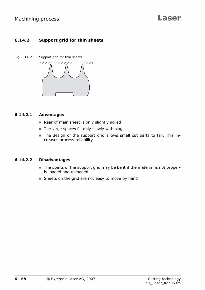
LaserMachining process
6.14.2 Support grid for thin sheets
Fig. 6.14-2 Support grid for thin sheets
6.14.2.1 Advantages
Rear of main sheet is only slightly soiled
The large spaces fill only slowly with slag
The design of the support grid allows small cut parts to fall. This in-creases process reliability
6.14.2.2 Disadvantages
The points of the support grid may be bent if the material is not proper-ly loaded and unloaded
Sheets on the grid are not easy to move by hand
6 - 68 Cutting technologyST_Laser_Kap06.fm
© Bystronic Laser AG, 2007
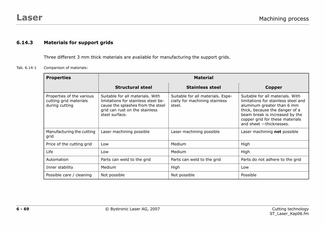
6 - 69 Cutting technologyST_Laser_Kap06.fm
Lase Machining process
6.14.3
Tab. 6.14-1
support grids.
aterial
less steel Copper
l materials. Espe-ining stainless
Suitable for all materials. With limitations for stainless steel and aluminum greater than 6 mm thick, because the danger of a beam break is increased by the copper grid for these materials and sheet —thicknesses.
ng possible Laser machining not possible
High
High
to the grid Parts do not adhere to the grid
Low
Possible
© Bystronic Laser AG, 2007
r
Materials for support grids
Comparison of materials:
Three different 3 mm thick materials are available for manufacturing the
Properties M
Structural steel Stain
Properties of the various cutting grid materials during cutting
Suitable for all materials. With limitations for stainless steel be-cause the splashes from the steel grid can rust on the stainless steel surface.
Suitable for alcially for machsteel.
Manufacturing the cutting grid
Laser machining possible Laser machini
Price of the cutting grid Low Medium
Life Low Medium
Automation Parts can weld to the grid Parts can weld
Inner stability Medium High
Possible care / cleaning Not possible Not possible
LaserMachining process
Taking both the advantages and disadvantages of the geome-tries and material properties into consideration, it can be seenthat there is no optimum grid for all applications.The two tables of the shuttle table system can be equipped withdifferent support grids. This offers the advantage that the mostsuitable can be selected respectively.
6 - 70 Cutting technologyST_Laser_Kap06.fm
© Bystronic Laser AG, 2007

Laser Machining process
6.15 Low-staff production
The most important criterion for low-staff production is process safety.Procedure and working practice is therefore considerably different to nor-mal production.
6.15.1 Recommendations
Only process cutting plans optimized for process safety in a mannedshift. In particular, erect or tilted parts must be prevented (see Chap-ters 6.12 ›Microjoints‹ and 8.2.7 ›Erect parts after machining‹). Criticalpart sizes range from 20 mm to approx. 150 mm.
Ensure that the long side of the parts lies perpendicular to the grid. Inmany cases this can prevent tilting.
Cut only simple part geometries
Cut only simple sheet thicknesses (e.g. 3 mm)
Optimize cutting parameters. A reduction in the feed rate of approx.10 ... 20% increases the process reliability significantly
Use CPP for piercing where possible
Monitor cutting with CutControl where possible
Use the nozzle cleaner
Use suitable main sheets (see Chapter 7 ›Materials‹)
6 - 71Cutting technologyST_Laser_Kap06.fm
© Bystronic Laser AG, 2007

LaserMachining process
6 - 72 Cutting technologyST_Laser_Kap06.fm
© Bystronic Laser AG, 2007

Laser
Chapter 7
7 Materials
This chapter describes the factors specific to the material that influencethe cutting process.
7 - 1Cutting technologyST_Laser_Kap07.fm
© Bystronic Laser AG, 2007

LaserMaterials
7.1 Material properties
The cutting result on the workpiece can be a perfectly clean cut or aragged and burred cut edge.
The following are regarded as the principal influence factors on the cutquality:
alloy constituents,
microstructure,
material surface
surface treatment
beam reflection,
thermal conductivity,
melting point.
7.1.1 alloy constituents,
Alloy constituents have a substantial influence on the strength, density,weldability, and oxide and acid resistance of the materials. Significant al-loy elements of steels are carbon, chromium, nickel, magnesium and zinc.
The higher the carbon content, the more difficult is the material to cut(critical limit at about 0.8% carbon).
The following carbon steels can be cut well with the laser:
St 37-2, StW 22, DIN 1.203
The cutting quality and cutting performance are dependent on the alloycomponents. In structural steel, a greater content of Si creates a roughcut edge and increases slag formation and burring. Carbon content>0.16% can lead to poor results on sharp edges and small holes.
We recommend you use laser sheets having controlled alloy constituentswhen working at the extreme sheet-thickness range.
Tab. 7.1-1 C and Si content
Material C content Si content
RAEX 250 0,12% 0,01%
RAEX 420 0,13% 0,01%
7 - 2 Cutting technologyST_Laser_Kap07.fm
© Bystronic Laser AG, 2007

Laser Materials
7.1.2 microstructure,
Generally speaking, the finer the grain of the material structure, the bet-ter the quality of the cut face.
7.1.3 Material surface
Material surface has a very significant influence on cutting results and cutquality.
7.1.3.1 Positive effects
fine, even surfaces with microscale
sheet lightly oiled,
pickled sheets
hot-rolled oiled main sheets.
Sandblasted and shot-peened surfaces are only suitable to a limited ex-tent but still better than rusty surfaces
Example:
Main sheets of the RAEX series, recommended by the machine manufac-turer
7.1.3.2 Negative effects
loose rolling skin,
rust,
scale,
uneven surface with troughs and irregularities,
general soiling,
steel stamping, rolled in defects,
color markings.
Primer or color
Example:
Cheap St 52 sheet, exposed to weathering
7 - 3Cutting technologyST_Laser_Kap07.fm
© Bystronic Laser AG, 2007

LaserMaterials
7.1.3.3 Oil
Piercing splashes adhere less well to oiled surfaces. This means that ca-pacitive sensing is disrupted less. Oiling can be carried out in a number ofways:
Working with Crossjet
Purchase oiled main sheets
Oil dry main sheets manually.
WARNINGFire risk
The oil on the sheet surface can be ignited by the laserbeam.
Flammable oils should not be used.
Always use welding protection oil(MOTOREX PROWELD 264)
7 - 4 Cutting technologyST_Laser_Kap07.fm
© Bystronic Laser AG, 2007
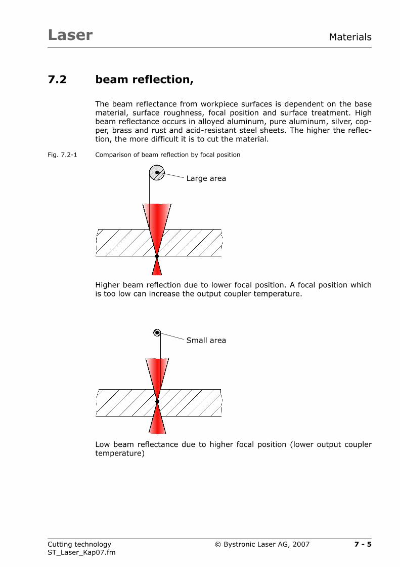
Laser Materials
7.2 beam reflection,
The beam reflectance from workpiece surfaces is dependent on the basematerial, surface roughness, focal position and surface treatment. Highbeam reflectance occurs in alloyed aluminum, pure aluminum, silver, cop-per, brass and rust and acid-resistant steel sheets. The higher the reflec-tion, the more difficult it is to cut the material.
Fig. 7.2-1 Comparison of beam reflection by focal position
Higher beam reflection due to lower focal position. A focal position whichis too low can increase the output coupler temperature.
Low beam reflectance due to higher focal position (lower output couplertemperature)
Large area
Small area
7 - 5Cutting technologyST_Laser_Kap07.fm
© Bystronic Laser AG, 2007
LaserMaterials
7.3 thermal conductivity,
Materials with low thermal conductivity require less power to melt the ma-terial than materials with a higher thermal conductivity.
For example, the power required for stainless steel is below the values forstructural steel, despite the lower absorption at the process temperature.
On the other hand, copper, aluminum and brass, for instance, conduct asubstantial portion of the heat generated by the absorption of the laserbeam away. The heat is quickly conducted away from the point of the laserbeam, hindering the local melting of the material.
7 - 6 Cutting technologyST_Laser_Kap07.fm
© Bystronic Laser AG, 2007
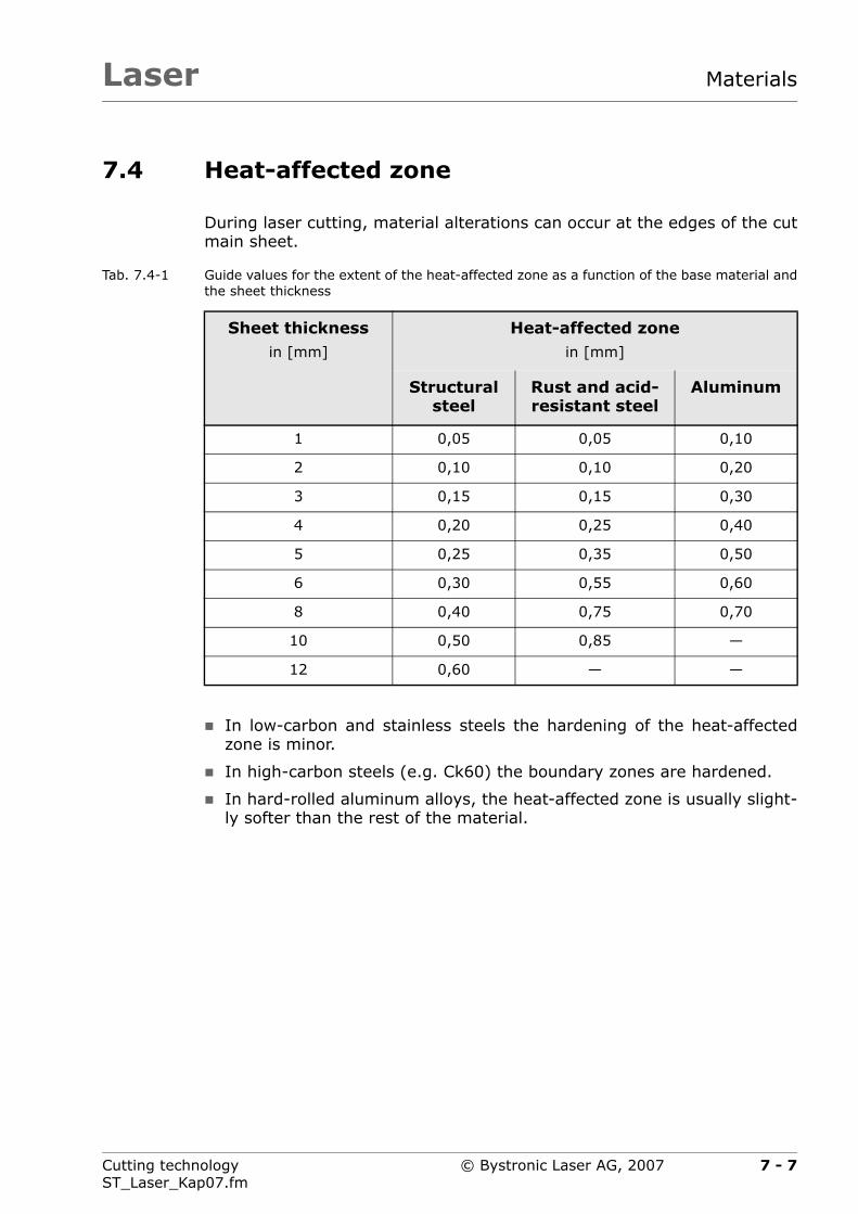
Laser Materials
7.4 Heat-affected zone
During laser cutting, material alterations can occur at the edges of the cutmain sheet.
Tab. 7.4-1 Guide values for the extent of the heat-affected zone as a function of the base material andthe sheet thickness
In low-carbon and stainless steels the hardening of the heat-affectedzone is minor.
In high-carbon steels (e.g. Ck60) the boundary zones are hardened.
In hard-rolled aluminum alloys, the heat-affected zone is usually slight-ly softer than the rest of the material.
Sheet thicknessin [mm]
Heat-affected zonein [mm]
Structural steel
Rust and acid-resistant steel
Aluminum
1 0,05 0,05 0,10
2 0,10 0,10 0,20
3 0,15 0,15 0,30
4 0,20 0,25 0,40
5 0,25 0,35 0,50
6 0,30 0,55 0,60
8 0,40 0,75 0,70
10 0,50 0,85 —
12 0,60 — —
7 - 7Cutting technologyST_Laser_Kap07.fm
© Bystronic Laser AG, 2007

LaserMaterials
7.5 Stresses
Cheap main sheets generally have substantially higher residual stressesand warp accordingly during laser cutting. The stresses are created duringmain sheet manufacture.
Qualitatively better main sheets posses lower residual stresses. Varyinglevels of stress can often be observed within one sheet. The greateststress levels are at the edges (during manufacture) because of the quickercooling here. Additional production reliability can be achieved by carefulnesting.
Fig. 7.5-1 Stress behavior across the complete main sheet
Area 1: Low-voltage zone. Parts that warp heavily should benested in this area (e.g. long, thin strips).
Area 2: High-voltage zone. Large, non-complex parts should benested here.
L
B
7 - 8 Cutting technologyST_Laser_Kap07.fm
© Bystronic Laser AG, 2007

Laser
Chapter 8
8 High-dynamic cutting
This chapter provides information on the special properties of high-dy-namic cutting with the Byspeed laser cutting machine.
8 - 1Cutting technologyST_Laser_Kap08.fm
© Bystronic Laser AG, 2007

LaserHigh-dynamic cutting
8.1 General instructions
In order to use this laser cutting machine to its optimum, the followingpoints must be observed for high-dynamic cutting in particular:
Part programming
Cutting parameters
Production
8.1.1 Application
High-dynamic cutting is used primarily for sheet thicknesses in the0.5 .... 1.5 range. Sheet thicknesses from 2 ... 3 mm are in a transitionzone.
From a sheet thickness of 4 mm upwards, the Byspeed machines operatethe same as the other laser cutting machines (with the exception of posi-tioning). No special measures are required above this sheet thickness.
8.1.2 Part programming
The programming of the single parts can influence the machining processconsiderably. Wrongly or below optimum programming of parts increasemachining time, can cause structural damage and increase wear on the la-ser cutting machine.
During ultra-dynamic cutting, the main sheet must be clamped.This reduces the usable surface (see Chapter 1.2.2 ›Minimumdistance from sheet edge‹
8 - 2 Cutting technologyST_Laser_Kap08.fm
© Bystronic Laser AG, 2007

Laser High-dynamic cutting
8.2 Optimum parts programming
The part geometry is programmed using the Bysoft CAD/CAM application.The machining technology is particularly important.
8.2.1 Initial cuts
Decide whether to work with or without initial cuts.
8.2.1.1 Machining without initial cuts
This is the fastest type of machining because piercing is directly on thecontour. The initial cut is dispensed with.
Disadvantage
The piercing point is visible even on the GO part. Machining without initialcuts speeds up cutting of templates drastically, but is usually only suitablefor sheets thicknesses up to 1.5 mm due to the quality.
8.2.1.2 Machining with initial cut
A new cut type was developed for the Byspeed laser cutting machine —so-called are initial cuts. These are supported by Bysoft Version 6.4 andhigher. The arc initial cuts allow a fine approach to the contour at highspeed and do not generate abrupt direction changes.
Fig. 8.2-1 Arc initial cuts with Byspeed
Arc initial cuts
8 - 3Cutting technologyST_Laser_Kap08.fm
© Bystronic Laser AG, 2007

LaserHigh-dynamic cutting
You can also use all other initial cuts supported by Bysoft. However, theseare not optimized for high-dynamic cutting.
In particular, the initial cut perpendicular to the contour is unsuitable be-cause the cutting dynamics are impeded.
8.2.1.3 Initial cut type
In the following table the corresponding initial cuts are assigned to the ap-propriate sheet thicknesses. However, different initial cut types can alsobe used for differing quality requirements.
Tab. 8.2-1 Initial cut types and their applications
Initial cut type Usage
Without initial cut (piercing on the contour)
High-dynamic cutting of 0.5 ... 1.5 mm thick sheets
Straight line at right angles to contour Pulsed contours, general applications
Arc initial cut High-dynamic cutting of 0.5 ... 3 mm thick sheets
Straight line with arc Sheet thickness 4 ... 20 mm, general applications
Straight tangential Sheet thickness 10 ... 20 mm, outer contours
8 - 4 Cutting technologyST_Laser_Kap08.fm
© Bystronic Laser AG, 2007

Laser High-dynamic cutting
8.2.1.4 Initial cut point
You must generally ensure that the initial cuts reach the length defined inBysoft. If they are automatically shortened, the initial cut point must beedited.
Tab. 8.2-2 Initial cut position
It is possible to use contours with and without an initial cut within onepart. For example, a template can be cut without initial cuts, all other ge-ometries with initial cuts.
Optimum initial cut position Poor initial cut positionLength is not achieved
8 - 5Cutting technologyST_Laser_Kap08.fm
© Bystronic Laser AG, 2007

LaserHigh-dynamic cutting
8.2.2 Direction of rotation and cutting sequence in the part
The direction of rotation and the cutting sequence should follow a dynamicsequence. Sharp changes of direction or reversals must be avoided.
Tab. 8.2-3 Direction of rotation and cutting sequence
Optimum direction of rotation and sequence
Poor direction of rotation and sequence
In templates with small and large contours, ensure that thesmall contours are always cut first.
Do not position above a contour that has already been cut.This avoids the risk of the cutting head possibly colliding witha tilted part.
8 - 6 Cutting technologyST_Laser_Kap08.fm
© Bystronic Laser AG, 2007

Laser High-dynamic cutting
Tab. 8.2-4 Cutting and positioning sequence
8.2.3 Positioning in Bysoft
The head should always be raised for each positioning. Raising increasesprocess reliability and is just as fast as the lowered positioning function.
Optimum cutting andpositioning sequence
Poor cutting sequence
In Bysoft, the machining sequence must be specified as Po-sitioning path optimized.
8 - 7Cutting technologyST_Laser_Kap08.fm
© Bystronic Laser AG, 2007

LaserHigh-dynamic cutting
8.2.4 Positioning the machine axes
In order to eliminate structural damage, the axes are not positioned instraight lines, but use straights and arcs.
This means of positioning is applied by using the Floating cut start andend parameter in the cutting parameters.
Arcs should always be used for high-dynamic cutting. The cutting parame-ters provided are accordingly defined for up to 3 mm sheet thickness.
8.2.5 Hole patterns
Hole templates are ideally cut in rows. The optimum initial cut is best donein the quadrant.
If cutting is done without an initial cut an initial cut must be defined for achange of row (if the row spacing is less than 8 mm) in order to avoidstructural damage.
Fig. 8.2-2 Optimum programmed hole template
Input value: 0 = off
1 = on
2 = on + arc
If the centers (A) are less than 8 mm, the initial cut must beapplied at a change of row.
A
8 - 8 Cutting technologyST_Laser_Kap08.fm
© Bystronic Laser AG, 2007

Laser High-dynamic cutting
8.2.6 Thin sheet machining using scanning
Scanning is the linear machining of rectangular and square holes. Linearmachining offers the advantage of requiring much fewer changes in direc-tion. This enables a substantially shorter cutting time.
Compared to conventional machining this can be up to 50% faster forscanning.
8.2.6.1 Schematic representation of the machining sequence
Machining with scanning is in two steps.
First step
First, all lines in an x-direction are processed (processing sequence1 ... 4). Cut contour segments are highlighted.
Fig. 8.2-3 First machining step with scanning
X
8 - 9Cutting technologyST_Laser_Kap08.fm
© Bystronic Laser AG, 2007

LaserHigh-dynamic cutting
Second step
After the x-direction the y-direction is processed (processing sequence5 ... 8). Cut contour segments are highlighted.
Fig. 8.2-4 Second machining step with scanning
8.2.6.2 Machining characteristics for scanning
Scanning can be used on all sheet types up to 2 mm thick.
Plasma cutting is a suitable method (see Chapter 6.8 ›Plasma cut‹).
Nitrogen (N2) is used as cutting gas for maximum cutting speed.
It often makes sense to use the process macro 2 cutting parametersfor the contours to be cut using scanning. This allows optimization ofthe part.
Scanning is generally only worthwhile for large series', because of theslightly greater programming effort. Bysoft supports programming ofscanning with a macro.
Scanning increases process reliability when cutting contours which donot always fall safely through the support grid. These contours can beadditionally cut one or more times without losing a great amount oftime.Microjoints can thus be avoided. The inner contours are all cut so smallthat they fall safely through the support grid.
During scanning, piercing takes place directly on the contour. If this isnot permissible, scanning cannot be used.
Y
8 - 10 Cutting technologyST_Laser_Kap08.fm
© Bystronic Laser AG, 2007

Laser High-dynamic cutting
8.2.6.3 Machining example
Scanning is suitable primarily for repeating hole templates (e.g. for cov-ers, cooling slots, mountings for filter pads).
Fig. 8.2-5 Cutting hole templates
8 - 11Cutting technologyST_Laser_Kap08.fm
© Bystronic Laser AG, 2007
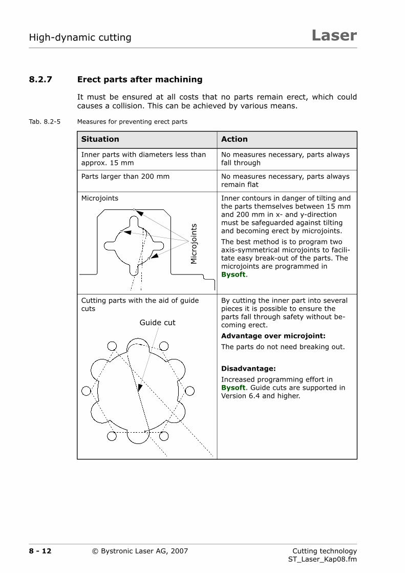
LaserHigh-dynamic cutting
8.2.7 Erect parts after machining
It must be ensured at all costs that no parts remain erect, which couldcauses a collision. This can be achieved by various means.
Tab. 8.2-5 Measures for preventing erect parts
Situation Action
Inner parts with diameters less than approx. 15 mm
No measures necessary, parts always fall through
Parts larger than 200 mm No measures necessary, parts always remain flat
Microjoints Inner contours in danger of tilting and the parts themselves between 15 mm and 200 mm in x- and y-direction must be safeguarded against tilting and becoming erect by microjoints.
The best method is to program two axis-symmetrical microjoints to facili-tate easy break-out of the parts. The microjoints are programmed in Bysoft.
Cutting parts with the aid of guide cuts
By cutting the inner part into several pieces it is possible to ensure the parts fall through safety without be-coming erect.
Advantage over microjoint:
The parts do not need breaking out.
Disadvantage:
Increased programming effort in Bysoft. Guide cuts are supported in Version 6.4 and higher.
Mic
rojo
ints
Guide cut
8 - 12 Cutting technologyST_Laser_Kap08.fm
© Bystronic Laser AG, 2007

Laser High-dynamic cutting
8.2.8 Thin sheet grids
To improve the safe falling through of parts even further, special thin sheetgrids can be employed. See Chapter 6.14 ›Support grids‹ for further infor-mation.
8.2.9 Part machining sequence
For high-dynamic cutting the main sheet is automatically clamped at threepoints on the left side. The cutting sequence should be selected so thatthe sheet remains stable as long as possible, i.e. from right to left.
The numbers in the following cutting plan indicate the part cutting se-quence.
Fig. 8.2-6 Part machining sequence
A Clamping area of main sheet. See section 1.2.2 ›Minimum distancefrom sheet edge‹
B Safety microjoints
C Machining the parts from right to left
21
22
20 19
18
17
16
15
14
13 12
11 10
9
8
7
6
5
43
2
1
A
C
B
8 - 13Cutting technologyST_Laser_Kap08.fm
© Bystronic Laser AG, 2007
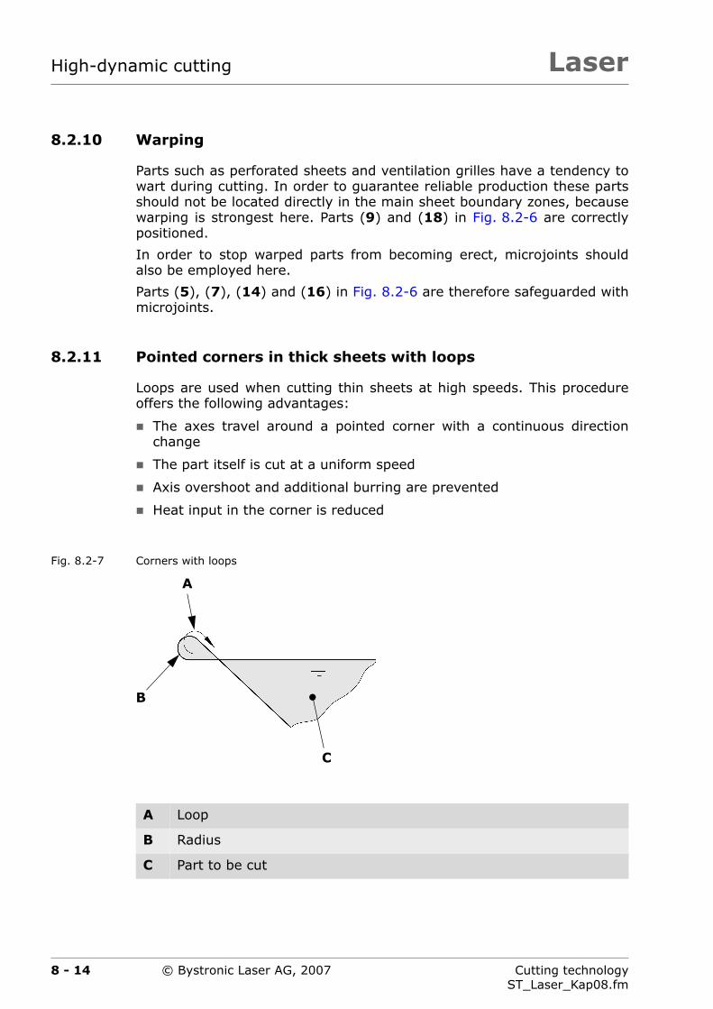
LaserHigh-dynamic cutting
8.2.10 Warping
Parts such as perforated sheets and ventilation grilles have a tendency towart during cutting. In order to guarantee reliable production these partsshould not be located directly in the main sheet boundary zones, becausewarping is strongest here. Parts (9) and (18) in Fig. 8.2-6 are correctlypositioned.
In order to stop warped parts from becoming erect, microjoints shouldalso be employed here.
Parts (5), (7), (14) and (16) in Fig. 8.2-6 are therefore safeguarded withmicrojoints.
8.2.11 Pointed corners in thick sheets with loops
Loops are used when cutting thin sheets at high speeds. This procedureoffers the following advantages:
The axes travel around a pointed corner with a continuous directionchange
The part itself is cut at a uniform speed
Axis overshoot and additional burring are prevented
Heat input in the corner is reduced
Fig. 8.2-7 Corners with loops
A Loop
B Radius
C Part to be cut
C
B
A
8 - 14 Cutting technologyST_Laser_Kap08.fm
© Bystronic Laser AG, 2007

Laser High-dynamic cutting
8.3 Cutting parameters
Special cutting parameters are available for high-dynamic cutting. Theseare identified by plasma cut in the additional information for the filename
Example:
A File name for cutting parameter
B Identifier for high-dynamic cutting (on-the-fly piercing)
A
B
8 - 15Cutting technologyST_Laser_Kap08.fm
© Bystronic Laser AG, 2007
LaserHigh-dynamic cutting
8.4 Production
In order to achieve maximum production reliability it is recommended toindividually test the parts to be cut with heavily reduced cutting and posi-tioning speed and the check the simulation in Bysoft. These points shouldbe observed:
Never position over a previously cut contour
Observe the direction of rotation for cutting and positioning
No erect parts
Processing the cutting plan from right to left
8 - 16 Cutting technologyST_Laser_Kap08.fm
© Bystronic Laser AG, 2007
Laser High-dynamic cutting
8.5 Quality of the main sheets
In the 0.5 ... 3 mm thickness range, special care should be taken that thesheets are high quality and are transported with care.
The sheets should be as flat as possible and not display any warping. Dur-ing storage, handling and transport sheets should be kept flat and not bebent.
8 - 17Cutting technologyST_Laser_Kap08.fm
© Bystronic Laser AG, 2007

LaserHigh-dynamic cutting
8 - 18 Cutting technologyST_Laser_Kap08.fm
© Bystronic Laser AG, 2007

Laser
Chapter 9
9 Tube processing
This chapter provides information on tube processing using the Bystar la-ser cutting machine.
9 - 1Cutting technologyST_Laser_Kap09.fm
© Bystronic Laser AG, 2007

LaserTube processing
9 - 2 Cutting technologyST_Laser_Kap09.fm
© Bystronic Laser AG, 2007

Laser Tube processing
9.1 General instructions
Tubes can only be cut on the Bystar machine type. This has an optional ro-tating axis.
Fig. 9.1-1 Example of a tube connection
Tubes are handled manually
During tube processing, the normal cutting parameters are adapted tothe tube in question (see Chapter 9.3 ›Adjustment of cutting parame-ters‹).
Programming is carried out in Bysoft. This supports many differentversions of cut-outs, penetrations and sections.
If the tube part is to be subsequently welded, we recommend you cutwith Nitrogen (N2) Cutting with oxygen (O2) produces a flaky layerwhich is not suitable for welding.
The maximum machined diameter is 315 mm
The maximum machined diameter is 15 mm
9 - 3Cutting technologyST_Laser_Kap09.fm
© Bystronic Laser AG, 2007

LaserTube processing
The liquefied metal remains inside the tube and can be welded firmly tothe opposite side. Oiling the inner side of the tube with a non-flammablewelding protection spray prior to cutting can reduce the particles' firmwelding effect.
Fig. 9.1-2 Firmly welded material
9 - 4 Cutting technologyST_Laser_Kap09.fm
© Bystronic Laser AG, 2007
Laser Tube processing
9.2 Reducing the heat
Unlike when welding main sheets, the laser beam and liquefied materialheats up the tube very strongly. The smaller the tube diameter to be ma-chined, the stronger the heat.
When laser cutting an overheated tube, the result is a reduction in thecutting quality.
The following measures reduce the heat in the tube:
Piercing
– Reduce Laser power, piercing or perform pulsed piercing (in struc-tural steel)
– Reduce Piercing time
Cutting
– Reduce Laser power, piercing or perform pulsed piercing (espe-cially in thin-walled steel tubes)
– Reduce Gas cutting pressure (especially when cutting steel tubeswith oxygen O2)
Selection of focal length
– Use 5" cutting head (instead of 7.5")
9 - 5Cutting technologyST_Laser_Kap09.fm
© Bystronic Laser AG, 2007
LaserTube processing
9.3 Adjustment of cutting parameters
1. Measure largest wall thickness of tube. When welded, measure tubesat weld seam.
2. Choose cutting gas (Nitrogen N2 or Oxygen O2)
3. Choose cutting parameter closest to measured wall thickness. If theall thickness lies between two thickness values, use the highestthickness.
4. Carry out heat reduction measures (see Chapter 9.2 ›Reducing theheat‹).
5. In many cases the Laser power, cutting and the Laser power,piercing may be reduced substantially.
9 - 6 Cutting technologyST_Laser_Kap09.fm
© Bystronic Laser AG, 2007

Laser Tube processing
9.4 Machining square and rectangular tubes
It is more difficult to cut across the corner area than on the flat sides ofthe tube. There is a particular strong risk of localized overheating.
Fig. 9.4-1 Cutting across corner area
When cutting with Oxygen (O2) it can be useful to cut the corner areasusing pulsed cutting. This reduces the heat input greatly and improvesparts quality. Programming is easy to carry out in Bysoft.
The parameter Y-feed rate, corner approach can be used to adjustthe cutting speed in the corner area.
Increasing the value of the parameter Nozzle clearance height forcutting to 1 ... 1.2 mm can improve parts quality around the cornersto a certain extent.
9 - 7Cutting technologyST_Laser_Kap09.fm
© Bystronic Laser AG, 2007

LaserTube processing
9.5 Quality of tubes and precision
The tubes contain enormous internal stresses from their manufacturewhich may be released during laser cutting depending on the geometry.This reduces the precision of the cut tube. Cheaper tubes on the marketoften have greater stresses than more expensive ones.
In cheaper tubes, the homogeneity of the alloying on the inside of thetube is not always constant. This means the cutting quality is not al-ways constant, especially when cutting steel tubes with Oxygen (O2).Cutting with nitrogen N2 helps.
Parts precision can often be improved substantially by choosing theright cutting sequence within the part.
Tubes have large shape and dimensional tolerances. This means that atube may arrive twisted or bent upon delivery. During laser cutting themachine does not take these inaccuracies into account and a poorerparts quality arises as a result.
Use tubes which are suitable for laser cutting. Your tube sup-plier will advise you.
Bent tubes can be straightened using appropriate heat treat-ment.
9 - 8 Cutting technologyST_Laser_Kap09.fm
© Bystronic Laser AG, 2007

Laser
Chapter 10
10 Repositioning machines
This chapter provides information on the machining of oversized mainsheets using the Bystar L laser cutting machine.
10 - 1Cutting technologyST_Laser_Kap10.fm
© Bystronic Laser AG, 2007

LaserRepositioning machines
10 - 2 Cutting technologyST_Laser_Kap10.fm
© Bystronic Laser AG, 2007

Laser Repositioning machines
10.1 General instructions
Special attention must be paid when creating cutting plans for cuttingoversized main sheets (see Chapter 10.2 ›Creating the cutting plan‹).Well thought-out cutting plans improve parts quality and precision andmake residual grid disposal easier.
Oversized main sheets do not normally have the usual sheet qualitycompared with formats up to 3 000 × 1 500 mm. The surface is corrod-ed or burned out in places, especially with sheet thicknesses above8 mm. To improve cutting quality it may be useful to remove the cor-roded surface by shot peening or sand blasting.
Main sheets have in places large internal stresses or inhomogeneouscrystal structures from their manufacture. This can reduce parts quality.
Your local steel trade can offer you advice on the varioussheet qualities.
10 - 3Cutting technologyST_Laser_Kap10.fm
© Bystronic Laser AG, 2007
LaserRepositioning machines
10.2 Creating the cutting plan
The cutting plans are created with Bysoft. The following points must beobserved:
Alternating machining is suitable for cutting plans containing long andstrip-shaped parts.
Strip-shaped parts are meant to be nestled in the middle of the mainsheet. This is usually where the least stresses are on the main sheet.This ensures higher parts precision, and means the parts rise up lessduring the cutting process.
Residual grid cuts in the X and Y direction are necessary to ensure asafe cutting process. These prevent the parts and remaining sheet cutsfrom rising up or becoming distorted during cutter and makes it easierto remove the residual grid. It is worth displacing the parts or residualgrid cuts so that there are as few interruptions as possible. If a residualgrid cut cuts through the whole sheet, this also prevents the heat fromspreading (residual grid cut as heat separation). This may be helpful forthicker sheets.
Nest the parts in such a way so that as few contours (inner and outercontours) as possible lie on the separating position. This increases partsprecision.
Contours which are interrupted by a separating position require pulsedpiercing (when piercing directly on the contour) if the material used al-lows for this. If this is not possible, normal piercing (CW) moving to-wards the contour with an initial cut.
10 - 4 Cutting technologyST_Laser_Kap10.fm
© Bystronic Laser AG, 2007

Laser Repositioning machines
Fig. 10.2-1 Cutting plan for oversized main sheets
A Laser machine cutting area
B Remaining Grid Cuts
C Separating position
D Long and strip-shaped parts
B
BBB
A
C
D
10 - 5Cutting technologyST_Laser_Kap10.fm
© Bystronic Laser AG, 2007
LaserRepositioning machines
10.3 Production
You normally need to edit the following cutting parameters when cuttingcorroded or poor quality main sheets:
Reduce Feed rate, cutting (in places up to 40%)
Reduce Laser cutting power
Nozzle diameter (use next largest diameter)
When cutting structural steel with Oxygen (O2), CPP piercing increasesproduction safety. See Chapter 6.3 ›Cutting structural steel‹
10 - 6 Cutting technologyST_Laser_Kap10.fm
© Bystronic Laser AG, 2007

Laser
Chapter 11
11 Cut evaluation
This chapter contains cut images which can be useful for evaluating andimproving cutting quality.
11 - 1Cutting technologyST_Laser_Kap11.fm
© Bystronic Laser AG, 2007

LaserCut evaluation
11 - 2 Cutting technologyST_Laser_Kap11.fm
© Bystronic Laser AG, 2007

Laser Cut evaluation
11.1 General instructions
The following images are magnified up to 10x. This is why striations andirregularities can even be seen on the optimum cut images.
The solutions described generally apply to all laser strengths
The solutions can also be extrapolated to other panel thicknesses
11 - 3Cutting technologyST_Laser_Kap11.fm
© Bystronic Laser AG, 2007
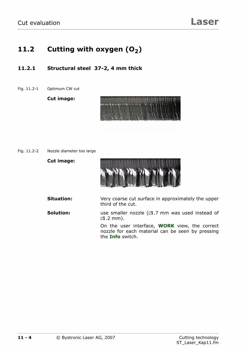
LaserCut evaluation
11.2 Cutting with oxygen (O2)
11.2.1 Structural steel 37-2, 4 mm thick
Fig. 11.2-1 Optimum CW cut
Fig. 11.2-2 Nozzle diameter too large
Cut image:
Cut image:
Situation: Very coarse cut surface in approximately the upperthird of the cut.
Solution: use smaller nozzle (∅1.7 mm was used instead of∅1.2 mm).
On the user interface, WORK view, the correctnozzle for each material can be seen by pressingthe Info switch.
11 - 4 Cutting technologyST_Laser_Kap11.fm
© Bystronic Laser AG, 2007

Laser Cut evaluation
Fig. 11.2-3 Laser power and gas pressure too low, nozzle diameter too small
Fig. 11.2-4 Optimum pulsed cut face
Cut image:
Situation: Cut parts do not fall out of the panel independent-ly. A bead of slag is found on the underside of thepanel. Good cut surface except the lower third.
Solution: Increase Laser power, cutting. Increase Gaspressure, cutting. Use larger nozzle.
Cut image:
Situation: rough, but regular cut surface (brown discolorationin the lower third). Pulsed cutting was used.
Solution: the figure shows an optimum pulsed cut surface.This is always rougher than the cut surface withCW cutting.
11 - 5Cutting technologyST_Laser_Kap11.fm
© Bystronic Laser AG, 2007
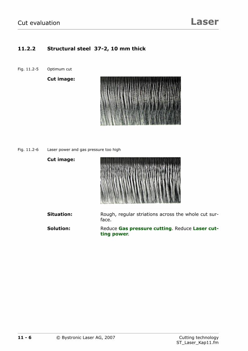
LaserCut evaluation
11.2.2 Structural steel 37-2, 10 mm thick
Fig. 11.2-5 Optimum cut
Fig. 11.2-6 Laser power and gas pressure too high
Cut image:
Cut image:
Situation: Rough, regular striations across the whole cut sur-face.
Solution: Reduce Gas pressure cutting. Reduce Laser cut-ting power.
11 - 6 Cutting technologyST_Laser_Kap11.fm
© Bystronic Laser AG, 2007

Laser Cut evaluation
Fig. 11.2-7 Feed rate too great
Fig. 11.2-8 Feed rate too low, laser power too high
Cut image:
Situation: Cut parts do not fall out of the panel independent-ly. Very high drag across the cut surface, especiallythe lower third.
A bead of slag is found on the underside of thepanel. Irregular cut surface.
Solution: reduce feed rate.
Cut image:
Situation: Coarse, regular striations across the complete cutsurface.
Solution: Increase feed rate greatly. The example was cut athalf of the normal feed rate.
Reduce Laser cutting power.
11 - 7Cutting technologyST_Laser_Kap11.fm
© Bystronic Laser AG, 2007

LaserCut evaluation
Fig. 11.2-9 Focal position too high
Fig. 11.2-10 Focal position too low
Cut image:
Situation: Coarse, regular striations on the upper face of thepanel.
Irregular cut surface.
A bead of slag may be found on the underside ofthe panel.
Solution: Bring the focal position, cutting deeper (in thefigure it is 5 mm too high).
Cut image:
Situation: Coarse, irregular cut surface.
Solution: Bring the focal position, cutting higher (in thefigure it is 5 mm too low).
11 - 8 Cutting technologyST_Laser_Kap11.fm
© Bystronic Laser AG, 2007

Laser Cut evaluation
11.2.3 Structural steel, 15 mm thick
Fig. 11.2-11 Reduce laser power and feed rate, nozzle diameter too small
Cut image: Surface
Cut surface with de-fault parameters
Cut surface with adapt-ed cutting parameters
Situation: Sand-blasted, heavily corroded surface.
The main sheet heats up strongly during cutting.
The top of the cut surface is very rough with heavystriations. In part very heavy burns across thewhole cut surface.
Solution: Reduce Laser cutting power
– Default value: 4 000 W
– adjusted value: 3 300 W
Reduce feedrate
– Default value: 1 300 mm/min
– adjusted value: 1 100 mm/min
Use a larger nozzle
– NK 20 instead of NK 17
11 - 9Cutting technologyST_Laser_Kap11.fm
© Bystronic Laser AG, 2007

LaserCut evaluation
11.2.4 Structural steel RAEX 420 Laser, 20 mm thick
Fig. 11.2-12 Optimum cut with NK nozzle
Fig. 11.2-13 Wrong nozzle shape used
Cut image:
Cut image:
Situation: Irregular, wavy cut surface in approximately theupper third of the cut, with burns.
Solution: Use NK nozzle instead of HK nozzle.
On the user interface, WORK view, the correctnozzle for each material can be seen by pressingthe Info switch.
11 - 10 Cutting technologyST_Laser_Kap11.fm
© Bystronic Laser AG, 2007

Laser Cut evaluation
Fig. 11.2-14 The heat concentration on the main sheet is too high
Cut image:
Situation: Cut parts do not fall out of the sheet independently(are partially fused).
Very rough, irregular cut surface. Slag is not com-pletely blown out.
Wide cut gap, particularly when starting and afterpiercing.
Solution: The main sheet is much too hot. User laser sheetsuch as RAEX.
Do not cut parts consecutively, but only every sec-ond part.
11 - 11Cutting technologyST_Laser_Kap11.fm
© Bystronic Laser AG, 2007

LaserCut evaluation
11.2.5 Rust and acid-resistant steel 1.4301, 6 mm thick
Fig. 11.2-15 Optimum cut with oxygen
Fig. 11.2-16 Focal position too low
Cut image:
Situation: Optimum cut with oxygen. The cut surface is muchcoarser than with nitrogen.
The cut surface is oxidized. Easily removable beadsoften form on the panel underside.
Cut image:
Situation: Cur surface is concave and has a coarse structure.Heavy bead formation on the underside of the pan-el.
Solution: Raise the focal position, cutting (in the figure itis 3 mm too low).
11 - 12 Cutting technologyST_Laser_Kap11.fm
© Bystronic Laser AG, 2007

Laser Cut evaluation
11.3 Cutting with nitrogen (N2)
11.3.1 Structural steel, hot galvanized, 2 mm thick
Fig. 11.3-1 Optimum cut
Fig. 11.3-2 Feedrate too great
Fig. 11.3-3 Laser power too high
Cut image:
Situation: The cut surface is always considerably rougherthan without zinc. The cut changes with varyingzinc layer thickness. The thicker the zinc layer, therougher is the cut surface
There is always a very fine burr on the underside ofthe panel. Electroplated sheets produce a muchfiner cut image.
Cut image:
Situation: Irregular, deep fissures in the cut face.Brown color-ing downwards of the panel center.
Solution: Reduce Feedrate.
Cut image:
Situation: irregular, deep fissures in the cut face.
Solution: Reduce Laser cutting power.
11 - 13Cutting technologyST_Laser_Kap11.fm
© Bystronic Laser AG, 2007

LaserCut evaluation
11.3.2 Structural steel 37-2, 6 mm thick
Fig. 11.3-4 Optimum, oxide-free cut
Fig. 11.3-5 Focal position too high
Cut image:
Cut image:
Situation: Hard, blue colored burr on the underside of thepanel. Heavy drag in the lower third of the cut sur-face.
Solution: Bring the focal position, cutting deeper (in thefigure it is 7 mm too high).
11 - 14 Cutting technologyST_Laser_Kap11.fm
© Bystronic Laser AG, 2007

Laser Cut evaluation
Fig. 11.3-6 Focal position set too low
Fig. 11.3-7 Gas pressure too low
Cut image:
Situation: Rough, somewhat irregular cut from the panel cen-ter down. Partial bead formation on the undersideof the panel.
Solution: Bring the Focal position, cutting higher (in thefigure it is 3 mm too low).
Cut image:
Situation: Fine cut in the upper region of the cut surface.However, the melted material is not completelyblown out.
Hard burr on the underside of the panel.
Solution: Increase the Gas pressure, cutting (in the figureit is 5 bar too low).
11 - 15Cutting technologyST_Laser_Kap11.fm
© Bystronic Laser AG, 2007

LaserCut evaluation
11.3.3 Rust and acid-resistant steel 1.4301, 6 mm thick
Fig. 11.3-8 Optimum, oxide-free cut
Cut image:
11 - 16 Cutting technologyST_Laser_Kap11.fm
© Bystronic Laser AG, 2007

Laser Cut evaluation
11.3.4 Rust and acid-resistant steel 1.4301, 10 mm thick
Fig. 11.3-9 Optimum cut
Fig. 11.3-10 Focal position too high
Cut image:
Cut image:
Situation: Heavy (only removable mechanically) sharp burron the underside of the panel.
Good cut, may have rougher cut surface from pan-el center.
Solution: Bring the focal position, cutting deeper (in thefigure it is 7 mm too high).
Increase gas pressure. The increased gas pressureejects the molten material better.
11 - 17Cutting technologyST_Laser_Kap11.fm
© Bystronic Laser AG, 2007
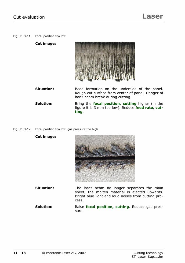
LaserCut evaluation
Fig. 11.3-11 Focal position too low
Fig. 11.3-12 Focal position too low, gas pressure too high
Cut image:
Situation: Bead formation on the underside of the panel.Rough cut surface from center of panel. Danger oflaser beam break during cutting.
Solution: Bring the focal position, cutting higher (in thefigure it is 3 mm too low). Reduce feed rate, cut-ting.
Cut image:
Situation: The laser beam no longer separates the mainsheet, the molten material is ejected upwards.Bright blue light and loud noises from cutting pro-cess.
Solution: Raise focal position, cutting. Reduce gas pres-sure.
11 - 18 Cutting technologyST_Laser_Kap11.fm
© Bystronic Laser AG, 2007

Laser Cut evaluation
Fig. 11.3-13 Gas pressure too low
Fig. 11.3-14 Feed rate too low
Cut image:
Situation: Heavy burr on the underside of the panel. Washedout, irregular cut surface with heavy drag from ap-prox. center of panel thickness.
Solution: Increase gas pressure (in the figure it is 4 bar toolow).
Cut image:
Situation: Clean cut surface in the upper two thirds of the cutsurface.
Heavy drag in the lower third of the cut surface.Heavy (only removable mechanically) sharp burron the underside of the panel.
Solution: Increase the Feedrate, cutting (in the figure it isonly half of the default value). Increase Cuttinggas pressure.
11 - 19Cutting technologyST_Laser_Kap11.fm
© Bystronic Laser AG, 2007

LaserCut evaluation
Fig. 11.3-15 Feedrate too great
Fig. 11.3-16 Beam diameter too large
Cut image:
Situation: Good quality in the upper half of the cut surface.Increasing roughness and increasing drag in lowerhalf of the cur surface.
Solution: Reduce the Feed rate, cutting (in the figure it is20% greater than the default value).
Cut image:
Situation: Good quality in the upper half of the cut surface.Increasing roughness and increasing drag in lowerhalf of the cur surface.
Bead formation on the underside of the panel.
Solution: Reduce the beam diameter, cutting (in the figure itis 1.5 mm more than the default value).
11 - 20 Cutting technologyST_Laser_Kap11.fm
© Bystronic Laser AG, 2007

Laser Cut evaluation
11.3.5 Rust and acid-resistant steel 1.4301, 20 mm thick
Fig. 11.3-17 Optimum plasma cut
Cut image:
Situation: Optimum plasma cut. Coarse, regular cut surfacewith wavy drag.
Removable bead formation on the underside of thepanel.
Solution: If the quality is insufficient, a different cuttingmethod must be considered (e.g. water jet cut-ting).
11 - 21Cutting technologyST_Laser_Kap11.fm
© Bystronic Laser AG, 2007

LaserCut evaluation
11.3.6 Aluminum AlMg3, 3 mm thick
Fig. 11.3-18 Optimum cut
Fig. 11.3-19 Gas pressure too high
Fig. 11.3-20 Laser power too high
Cut image:
Situation: optimum cut.
Cut image:
Situation: strong irregularities in cut. Blue flashes in cuttinggap when cutting.
Solution: Reduce Cutting gas pressure (in the figure it is3 bar too high).
Cut image:
Situation: strong irregularities in cut. Blue flashes in cuttinggap when cutting.
Solution: Reduce Laser cutting power.
11 - 22 Cutting technologyST_Laser_Kap11.fm
© Bystronic Laser AG, 2007

Laser Cut evaluation
Fig. 11.3-21 Focal position too high
Fig. 11.3-22 Focal position set too low
Cut image:
Situation: fine cut face in the upper two thirds of the cut.
Heavy drag in the lower third of the cut face. Hard,difficult to remove burr on the underside of thepanel.
Solution: Set the Focusing position, cutting lower (in thefigure it is 2 mm too high).
Cut image:
Situation: Clean cut face. Bead formation on the underside ofthe panel.
Solution: Set the Focusing position, cutting higher (in thefigure it is 2 mm too low).
11 - 23Cutting technologyST_Laser_Kap11.fm
© Bystronic Laser AG, 2007
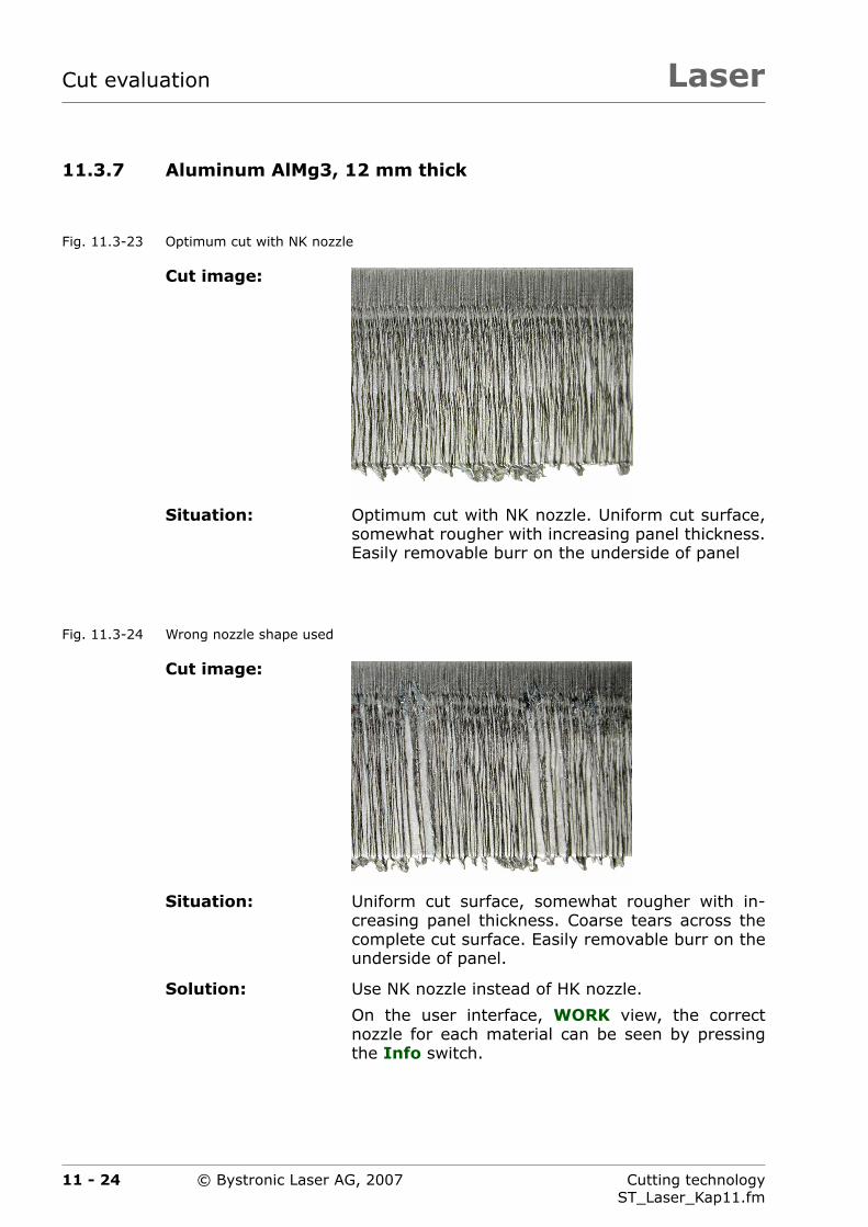
LaserCut evaluation
11.3.7 Aluminum AlMg3, 12 mm thick
Fig. 11.3-23 Optimum cut with NK nozzle
Fig. 11.3-24 Wrong nozzle shape used
Cut image:
Situation: Optimum cut with NK nozzle. Uniform cut surface,somewhat rougher with increasing panel thickness.Easily removable burr on the underside of panel
Cut image:
Situation: Uniform cut surface, somewhat rougher with in-creasing panel thickness. Coarse tears across thecomplete cut surface. Easily removable burr on theunderside of panel.
Solution: Use NK nozzle instead of HK nozzle.
On the user interface, WORK view, the correctnozzle for each material can be seen by pressingthe Info switch.
11 - 24 Cutting technologyST_Laser_Kap11.fm
© Bystronic Laser AG, 2007

Laser Cut evaluation
Fig. 11.3-25 Focal position too high, gas pressure too low
Cut image:
Situation: Uniform cut surface, somewhat rougher with in-creasing panel thickness. Hard, long burr.
Solution: Set the Focusing position, cutting lower (in thefigure it is 3 mm too high). Increase Cutting gaspressure.
11 - 25Cutting technologyST_Laser_Kap11.fm
© Bystronic Laser AG, 2007

LaserCut evaluation
11.3.8 Brass, 5 mm thick
Fig. 11.3-26 Optimum cut
Fig. 11.3-27 Focal position too low
Cut image:
Situation: optimum cut. Uniform cut surface, somewhatrougher with increasing panel thickness. Bead for-mation on the underside of the panel.
Cut image:
Situation: Uniform cut surface, somewhat rougher with in-creasing panel thickness. Brown-black coloringfrom main sheet center down.
Solution: Set the Focusing position, cutting higher (in thefigure it is 2.5 mm too low).
11 - 26 Cutting technologyST_Laser_Kap11.fm
© Bystronic Laser AG, 2007

Laser Cut evaluation
11.3.9 Copper, 3 mm thick
Fig. 11.3-28 Optimum cut
11.3.10 Titanium, 3 mm thick
Fig. 11.3-29 Optimum cut
Cut image:
Situation: optimum cut. Rougher cut surface with increasingpanel thickness. Because copper is very soft aheavy burr forms on the underside of the panel.
Cut image:
Situation: Optimum cut with nitrogen. Titan oxidizes whencut with nitrogen. This causes a brown to black col-oring across the complete cut surface. Hard, re-movable burr.
11 - 27Cutting technologyST_Laser_Kap11.fm
© Bystronic Laser AG, 2007
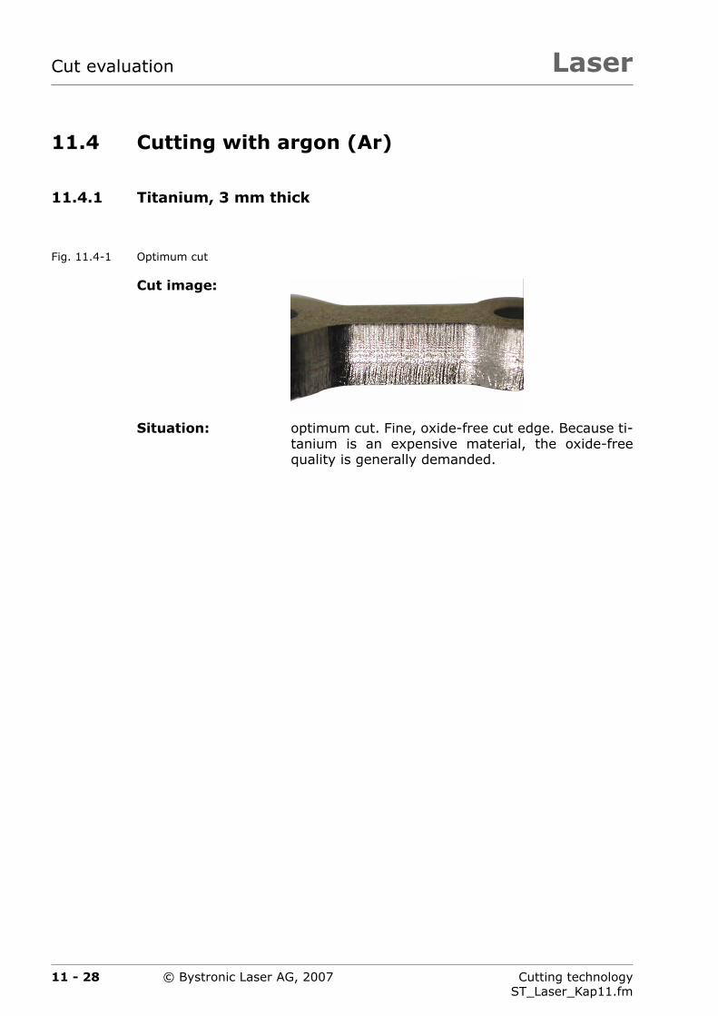
LaserCut evaluation
11.4 Cutting with argon (Ar)
11.4.1 Titanium, 3 mm thick
Fig. 11.4-1 Optimum cut
Cut image:
Situation: optimum cut. Fine, oxide-free cut edge. Because ti-tanium is an expensive material, the oxide-freequality is generally demanded.
11 - 28 Cutting technologyST_Laser_Kap11.fm
© Bystronic Laser AG, 2007
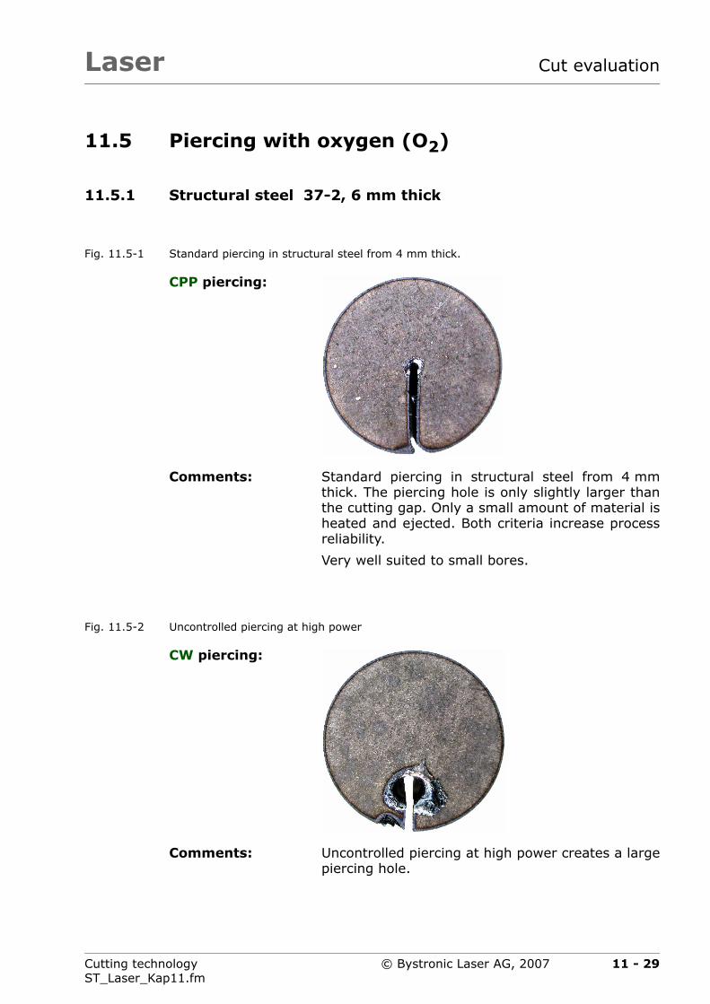
Laser Cut evaluation
11.5 Piercing with oxygen (O2)
11.5.1 Structural steel 37-2, 6 mm thick
Fig. 11.5-1 Standard piercing in structural steel from 4 mm thick.
Fig. 11.5-2 Uncontrolled piercing at high power
CPP piercing:
Comments: Standard piercing in structural steel from 4 mmthick. The piercing hole is only slightly larger thanthe cutting gap. Only a small amount of material isheated and ejected. Both criteria increase processreliability.
Very well suited to small bores.
CW piercing:
Comments: Uncontrolled piercing at high power creates a largepiercing hole.
11 - 29Cutting technologyST_Laser_Kap11.fm
© Bystronic Laser AG, 2007

LaserCut evaluation
11.6 Piercing with nitrogen (N2)
11.6.1 Rust and acid-resistant steel 1.4301, 2 mm thick
Fig. 11.6-1 Piercing on dry main sheets
CW piercing:
Comments: The melt ejected upwards during piercing is eject-ed on to the surface in a star shape. This can ad-here very strongly.
Small bores can interfere with capacitive sensing.This reduces the quality.
11 - 30 Cutting technologyST_Laser_Kap11.fm
© Bystronic Laser AG, 2007
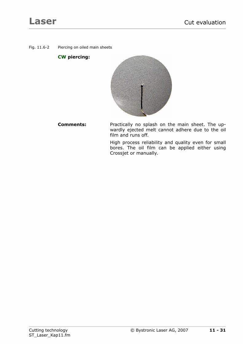
Laser Cut evaluation
Fig. 11.6-2 Piercing on oiled main sheets
CW piercing:
Comments: Practically no splash on the main sheet. The up-wardly ejected melt cannot adhere due to the oilfilm and runs off.
High process reliability and quality even for smallbores. The oil film can be applied either usingCrossjet or manually.
11 - 31Cutting technologyST_Laser_Kap11.fm
© Bystronic Laser AG, 2007

LaserCut evaluation
11.6.2 Rust and acid-resistant steel 1.4301, 10 mm thick
Fig. 11.6-3 Small piercing
Fig. 11.6-4 Large piercing
CW piercing:
Comments: Small piercing. The melt can fill the piercing afterstarting. This can cause the laser beam to break.
Highly suitable for piercing directly on the contour.
CW circular pierc-ing:
Comments: Large piercing. High process reliability for panelthicknesses above 6 mm.
The melt cannot fill the piercing after starting.
11 - 32 Cutting technologyST_Laser_Kap11.fm
© Bystronic Laser AG, 2007

Laser Cut evaluation
11.6.3 Aluminum AlMg3, 12 mm thick
Fig. 11.6-5 Large piercing
Fig. 11.6-6 Minimum piercing size
CW circular pierc-ing:
Comments: Large piercing using circular piercing. Excessiveejected melt can influence the capacitive sensingwhen cutting small holes.
Heavy soiling of the nozzle when piercing. This re-quires regular nozzle cleaning.
CPP piercing:
Comments: Minimum piercing size. Only little ejected melt.Small bores can be cut with high process reliability.
Minimum soiling of nozzle, therefore regular nozzlecleaning unnecessary. Long nozzle service life.
11 - 33Cutting technologyST_Laser_Kap11.fm
© Bystronic Laser AG, 2007
LaserCut evaluation
11.7 Quality of cut edges
Using oxygen O2 as the process gas produces an oxidized surface. Thissurface is not suitable for subsequent surface treatment (e.g. varnishing,staining, galvanizing etc.). The layer of oxide must be removed beforesubsequent surface treatment.
Using nitrogen N2 as the process gas produces an oxide-free surface.
Quality of the cut edge, see Chapter 1.3.2 ›Quality of the cut edge‹
11 - 34 Cutting technologyST_Laser_Kap11.fm
© Bystronic Laser AG, 2007

Laser
Chapter 12
12 Fault finding
This chapter provides support in finding the causes of deteriorations in cutquality.
12 - 1Cutting technologyST_Laser_Kap12.fm
© Bystronic Laser AG, 2007

LaserFault finding
12 - 2 Cutting technologyST_Laser_Kap12.fm
© Bystronic Laser AG, 2007
Laser Fault finding
12.1 General instructions
Optimum machining quality can only be achieved under the following con-ditions:
Precise adjustment of the laser cutting machine
Maintenance as per maintenance schedule
Working materials in accordance with requirements,
Workpiece surface is rust and cinder-free (etched, pickled or polished)
Suitable parameters for the material and panel thickness at hand
Parameters harmonized to each other
The following points must be examined if the machining quality falls com-pared to previous results:
1. Parameters
2. Cutting head
3. Beam guidance system
4. Laser module
12 - 3Cutting technologyST_Laser_Kap12.fm
© Bystronic Laser AG, 2007

LaserFault finding
12.2 Parameters
Never overwrite the default parameters delivered with the laser cuttingmachine.
A new folder must be created for the customized cutting parameters.
If cut quality deteriorates, examine whether the default parameters havebeen changed substantially compared to your customized parameters.
12 - 4 Cutting technologyST_Laser_Kap12.fm
© Bystronic Laser AG, 2007

Laser Fault finding
12.3 Cutting head
Focal length in accordance with parameters
Nozzle shape according to parameters,
Lens clean
Nozzle centered accurately
Focal position
Lens correctly mounted and fixed.
Check water cooling on cutting head
12 - 5Cutting technologyST_Laser_Kap12.fm
© Bystronic Laser AG, 2007

LaserFault finding
12.4 Beam guidance system
Deflecting mirror (cleanliness, fit, cooling)
Cutting head positions 1 ... 4 for adjusting the optics
Laser mode in Plexiglas cube
Positive pressure in the beam channel and bellows
Solvents in the ambient air
Sufficient air quality for the beam channel ventilation
12 - 6 Cutting technologyST_Laser_Kap12.fm
© Bystronic Laser AG, 2007

Laser Fault finding
12.5 Laser module
Optical impression of gas discharge
Power check
Tube current
Positive pressure in output coupler
Polarizing mirror
Beam divergence system
Density of laser
Output coupler (service)
Total reflector (service)
Deflecting mirror (service)
12 - 7Cutting technologyST_Laser_Kap12.fm
© Bystronic Laser AG, 2007

LaserFault finding
12 - 8 Cutting technologyST_Laser_Kap12.fm
© Bystronic Laser AG, 2007