The usability of terrestrial 3D laser scanning technology for tunnel clearance analysis application
7
The usability of terrestrial 3D laser scanning technology for tunnel clearance analysis application Gregor Novaković 1a , Aleš Lazar 1b , Simon Kovačič 2c , Milivoj Vulić 3d 1 3D ATA Ltd. Kranj, Slovenia 2 Slovenian railway infrastructure Ltd. Ljubljana, Slovenia 3 Faculty of Natural Sciences and Engineering, Chair for Mine Surveying and Applied Geophysics, Ljubljana, Slovenia a [email protected], b [email protected], c [email protected], d [email protected] Keywords:Clearance analysis, Underground constructions, Terrestrial laser scanning, As Built models, Tunnel safety. Abstract After building underground constructions, spatial parameters monitoring is essential due to safety and statuary reasons. Therefore after completion of work in tunnels oftensupervision projects follow which include cross sections measurements, as well as ground and secondary wall layer deformations monitoringduring consolidation era. Conventional approaches to achieve this type of documentations are different, however their downside is often that they are time consuming andeven with combination of independent contractors, collected data is often deficient and corrupted with rough interpolations. Terrestrial 3D laser scanning (TLS) represents alternative approach to conventional monitoring methods [1]. With engineer planning approach, field work and data interpretation, TLS technology allows systematical and fast acquisition of shape and spatial orientation of complex objects and all their components. In case of shorter railway tunnels (up to 360 m) data for clearance analysis in correlation of standard cargo and tunnel surface, was captured with terrestrial 3D laser scanning method. Control of tunnel clearance is usually performed analogously and on conventional low equidistant cross section survey method. Considering that in this article we deal with relative old tunnels, in which there is no constant transversal profile but huge amount of geometric anomalies, simulation verification could be performed only with hi-grid definition survey method. With TLS larger amount of tunnels were measured and clearance analysis simulations for real case of standard cargo profile was made, based on radius and railway inclination of the tunnel. Standard or non-standard cargo transport planningwithcomputer simulation now can be done in relatively short time. In this article is presented integration of TLS in case study of short railway tunnels with focus on clearance analysis applications withinteractive and user friendlyvisualization for data interpretation. Other methods for different spatial parameters interpretations in underground constructions are presented as well. Introduction Before, during and after any construction process,monitoring and documenting the shape and spatial orientation of engineering objects is required and essential. Examined objects – railway tunnels – are older, thereforeshape changes of tunnel layer were required toensureminimal tunnel profile clearance standards.After finished construction work manifestation of changes of stress forces wereexpected in surrounding rock and the tunnel itself.In addition to regular deformation monitoring, it was necessary toensure technical documentation with measurements and produce 2D cross sections and control of achieving minimaltunnel profile clearance in the time of consolidation era.
-
Upload
independent -
Category
Documents
-
view
2 -
download
0
Transcript of The usability of terrestrial 3D laser scanning technology for tunnel clearance analysis application
The usability of terrestrial 3D laser scanning technology for tunnel clearance analysis application
Gregor Novaković1a, Aleš Lazar1b, Simon Kovačič2c, Milivoj Vulić3d
13D ATA Ltd. Kranj, Slovenia 2Slovenian railway infrastructure Ltd. Ljubljana, Slovenia
3Faculty of Natural Sciences and Engineering, Chair for Mine Surveying and Applied Geophysics, Ljubljana, Slovenia
[email protected], [email protected], [email protected],
[email protected] Keywords:Clearance analysis, Underground constructions, Terrestrial laser scanning, As Built models, Tunnel safety.
Abstract After building underground constructions, spatial parameters monitoring is essential due to
safety and statuary reasons. Therefore after completion of work in tunnels oftensupervision projects follow which include cross sections measurements, as well as ground and secondary wall layer deformations monitoringduring consolidation era. Conventional approaches to achieve this type of documentations are different, however their downside is often that they are time consuming andeven with combination of independent contractors, collected data is often deficient and corrupted with rough interpolations.
Terrestrial 3D laser scanning (TLS) represents alternative approach to conventional monitoring methods [1]. With engineer planning approach, field work and data interpretation, TLS technology allows systematical and fast acquisition of shape and spatial orientation of complex objects and all their components.
In case of shorter railway tunnels (up to 360 m) data for clearance analysis in correlation of standard cargo and tunnel surface, was captured with terrestrial 3D laser scanning method. Control of tunnel clearance is usually performed analogously and on conventional low equidistant cross section survey method. Considering that in this article we deal with relative old tunnels, in which there is no constant transversal profile but huge amount of geometric anomalies, simulation verification could be performed only with hi-grid definition survey method. With TLS larger amount of tunnels were measured and clearance analysis simulations for real case of standard cargo profile was made, based on radius and railway inclination of the tunnel. Standard or non-standard cargo transport planningwithcomputer simulation now can be done in relatively short time.
In this article is presented integration of TLS in case study of short railway tunnels with focus on clearance analysis applications withinteractive and user friendlyvisualization for data interpretation. Other methods for different spatial parameters interpretations in underground constructions are presented as well.
Introduction Before, during and after any construction process,monitoring and documenting the shape and
spatial orientation of engineering objects is required and essential. Examined objects – railway tunnels – are older, thereforeshape changes of tunnel layer were required toensureminimal tunnel profile clearance standards.After finished construction work manifestation of changes of stress forces wereexpected in surrounding rock and the tunnel itself.In addition to regular deformation monitoring, it was necessary toensure technical documentation with measurements and produce 2D cross sections and control of achieving minimaltunnel profile clearance in the time of consolidation era.

For creation of mentioned documentation, manager of constructions decided to use terrestrial 3D laser scanning (TLS) method. The scans were performed on tunnels between Pivka and Divača railway route (Slovenia) (Fig. 1).
Fig. 1: Railway route between Pivka and Divača, where 3D laser scan measurements were
performed.
Methods, Materials Terrestrial laser scanning (TLS). TLS is considered to be an effective measuring method of
comprehensive spatial data, describing the geometry of the visible object's surfaces. In a very short time, instrument systematically produces millions of 3D measurements, with a dense crowd of geo-located points as a direct result. Already, after a single capture and primary processing (registration of scan positions into a single coordinate system and filtration of pointclouds) these “point cloud” data accurately define a high detailed shape of the measured objects surfaces[2]. With the secondary process, the gathered data is useful in many engineering applications, such as 2D plans extraction[3], »as built« 3D models modeling, deformation monitoring [1, 2], »as build – as designed« comparisons, reverse engineering, etc...
Instrument characteristics. In order to achieve high accuracy with the discussed technology, a pulse based terrestrial 3D laser scanner Leica Scan-station C10 was chosen (Fig. 2). The pulse based instrument consists of a transmitter / receiver of laser beams. The distance of measurement is based on the time-of-flight of the laser pulse to travel and reflect from the measured surface. The location of each point is acquired in a polar coordinate system. The horizontal and vertical angles are modified by the scanning device using an internal system of rotating mirrors, which is synchronously saved with laser beam time travelling. Compared to conventional surveying methods, a TLS with Scanstation C10 shows a very high data acquisition speed (up to 50 000 pts/s).
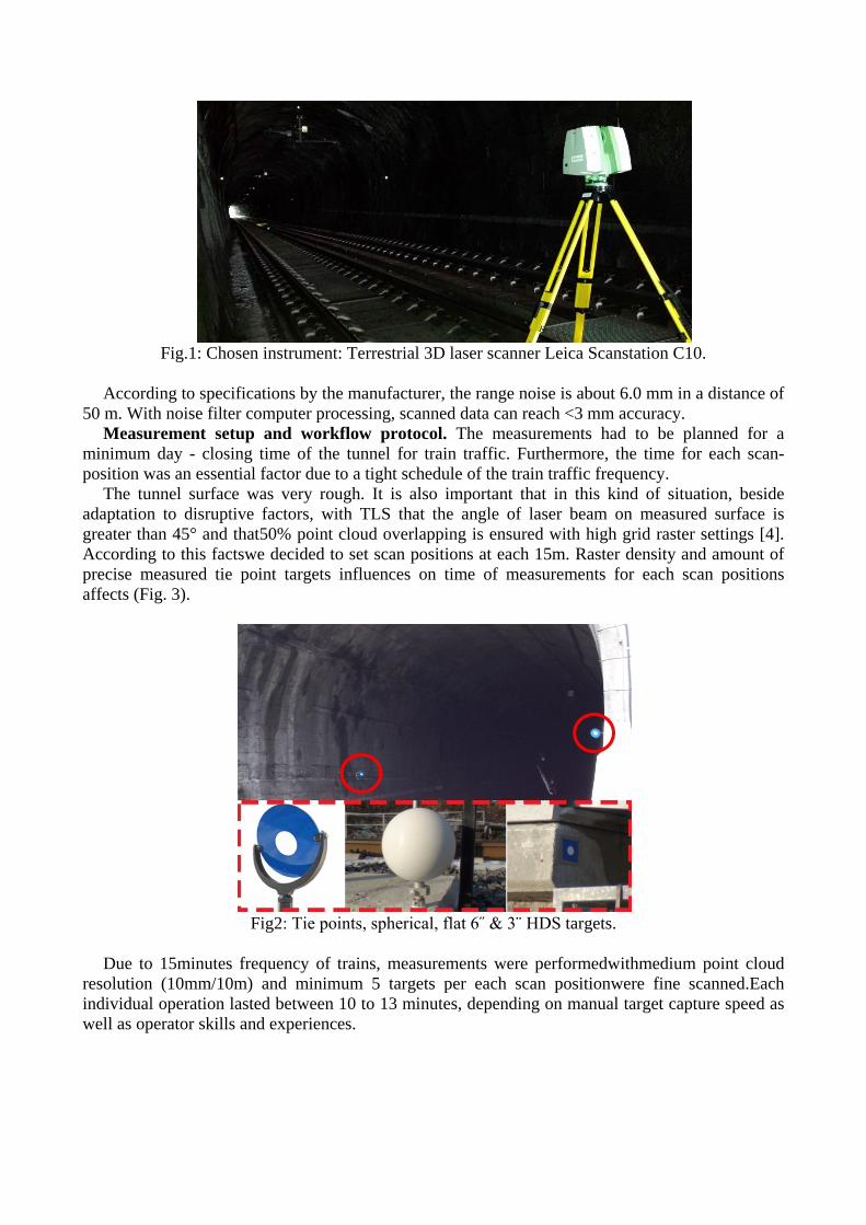
Fig.1: Chosen instrument: Terrestrial 3D laser scanner Leica Scanstation C10.
According to specifications by the manufacturer, the range noise is about 6.0 mm in a distance of
50 m. With noise filter computer processing, scanned data can reach <3 mm accuracy. Measurement setup and workflow protocol. The measurements had to be planned for a
minimum day - closing time of the tunnel for train traffic. Furthermore, the time for each scan-position was an essential factor due to a tight schedule of the train traffic frequency.
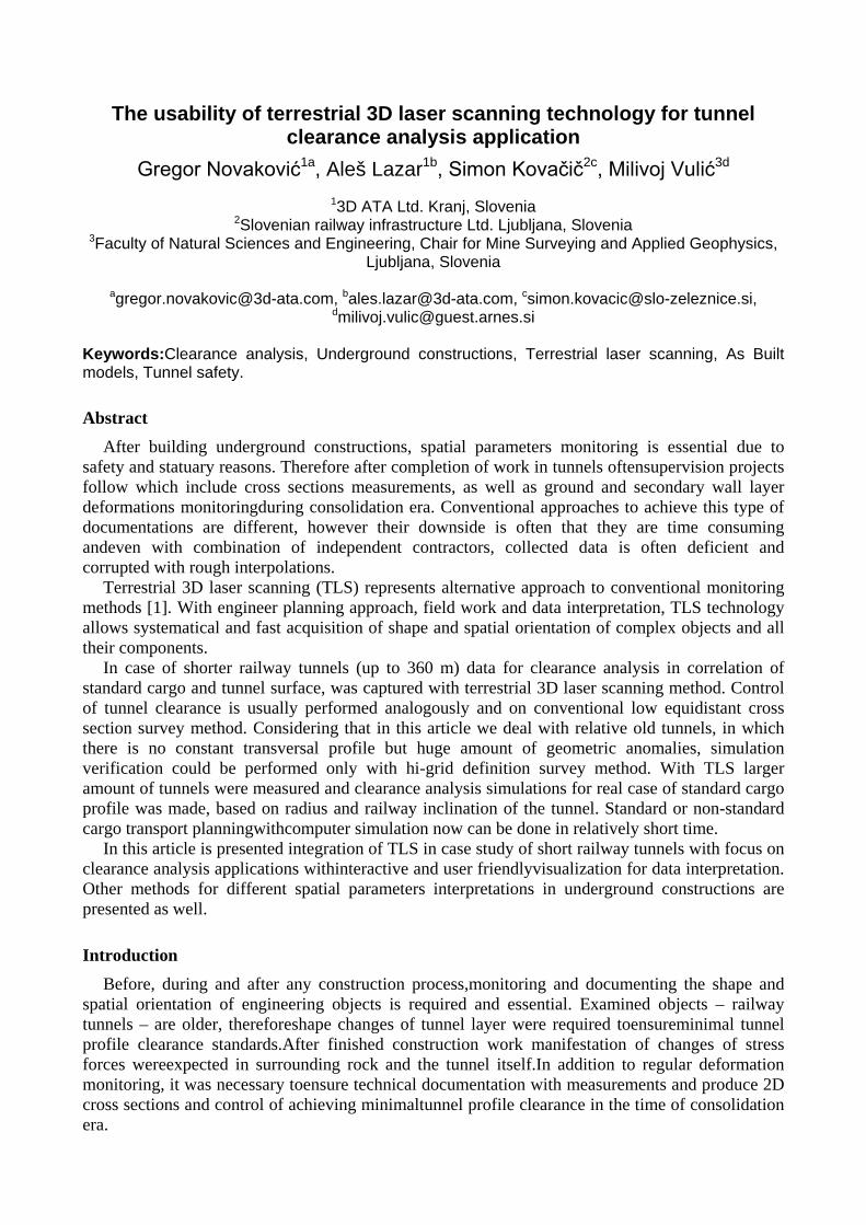
The tunnel surface was very rough. It is also important that in this kind of situation, beside adaptation to disruptive factors, with TLS that the angle of laser beam on measured surface is greater than 45° and that50% point cloud overlapping is ensured with high grid raster settings [4]. According to this factswe decided to set scan positions at each 15m. Raster density and amount of precise measured tie point targets influences on time of measurements for each scan positions affects (Fig. 3).
Fig2: Tie points, spherical, flat 6˝ & 3¨ HDS targets.
Due to 15minutes frequency of trains, measurements were performedwithmedium point cloud
resolution (10mm/10m) and minimum 5 targets per each scan positionwere fine scanned.Each individual operation lasted between 10 to 13 minutes, depending on manual target capture speed as well as operator skills and experiences.
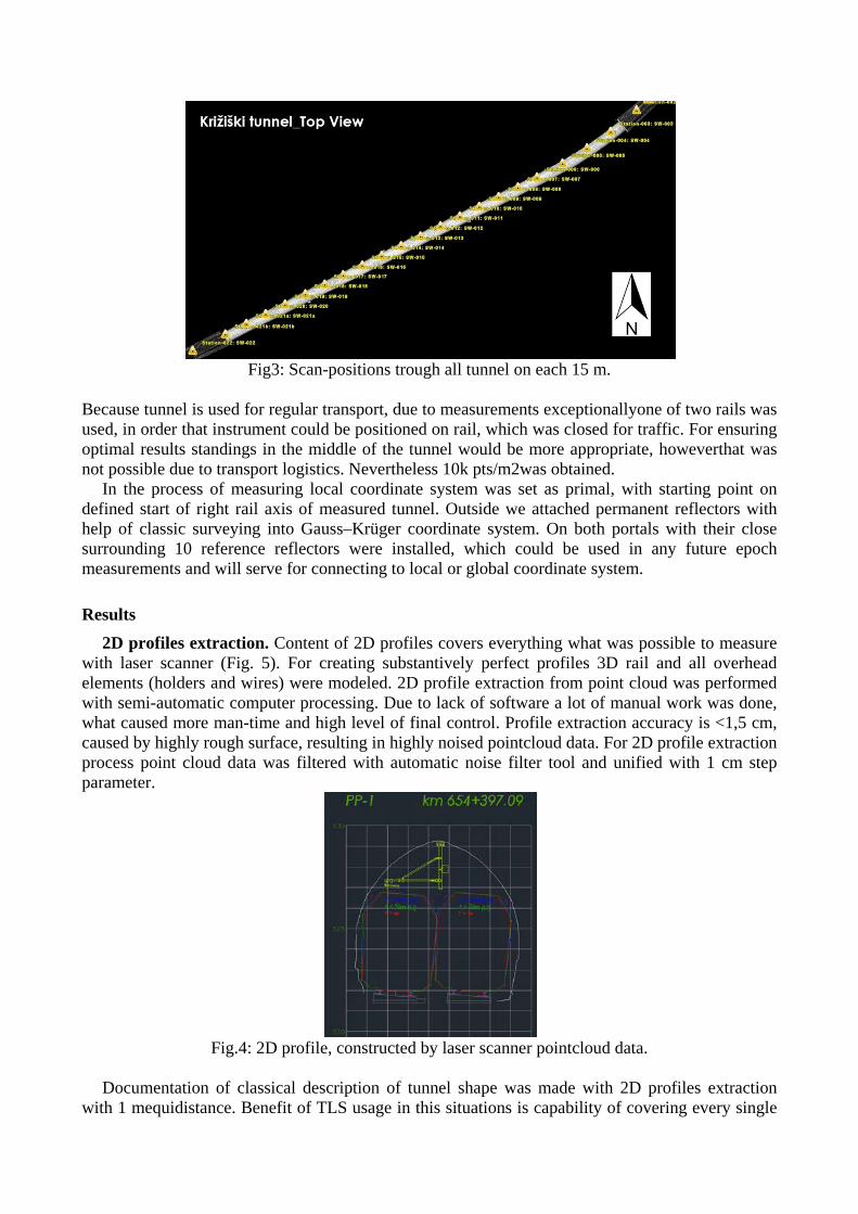
Fig3: Scan-positions trough all tunnel on each 15 m.
Because tunnel is used for regular transport, due to measurements exceptionallyone of two rails was used, in order that instrument could be positioned on rail, which was closed for traffic. For ensuring optimal results standings in the middle of the tunnel would be more appropriate, howeverthat was not possible due to transport logistics. Nevertheless 10k pts/m2was obtained.
In the process of measuring local coordinate system was set as primal, with starting point on defined start of right rail axis of measured tunnel. Outside we attached permanent reflectors with help of classic surveying into Gauss–Krüger coordinate system. On both portals with their close surrounding 10 reference reflectors were installed, which could be used in any future epoch measurements and will serve for connecting to local or global coordinate system.
Results 2D profiles extraction. Content of 2D profiles covers everything what was possible to measure
with laser scanner (Fig. 5). For creating substantively perfect profiles 3D rail and all overhead elements (holders and wires) were modeled. 2D profile extraction from point cloud was performed with semi-automatic computer processing. Due to lack of software a lot of manual work was done, what caused more man-time and high level of final control. Profile extraction accuracy is <1,5 cm, caused by highly rough surface, resulting in highly noised pointcloud data. For 2D profile extraction process point cloud data was filtered with automatic noise filter tool and unified with 1 cm step parameter.
Fig.4: 2D profile, constructed by laser scanner pointcloud data.
Documentation of classical description of tunnel shape was made with 2D profiles extraction
with 1 mequidistance. Benefit of TLS usage in this situations is capability of covering every single

detail with usage of extremely high density raster.Equidistance, direction and location profile extraction is unlimited [1, 5].
Tunnel Clearance Analysis.In post process interpretations and computer data analysis, cargo tunnel pass was simulated. From geo-located point cloud 3D representation of tunnel shape and two important spatial parameters was modeled, which defined actual state of rail axisand slope.
Fig.5: Oversized standard cargo profiles for linear&curve rail axis.
Beside modeled surfaces of actual tunnel shape, cargo was also modeled with axis and defined
slope considered. Wagon profile was defined according to standardsfor cargo (Fig. 6). Computer deviation analysis process was based on searching the shortest vector oriented from measured point towards surface of modeled cargo as a reference (Fig. 7).
Fig.6: Detail view of deviation analysis principle.
Analysis interpretation of tunnel clearance with detail presentation is visualized on map in 1:100
scale. It allows effective identification and size recognition of potential interaction among complete tunnel (Fig. 8).
Fig.7: Clearance analysis map in scale 1:100 for operative work.

Discussion In the future we will attempt to set scan positions in the middle of the tunnel profile or to
produce measurements in time of complete closure both of rails. In time of one day (up to 10 hours) detailed measurement of complete tunnel in length up to 400mcould be performed. For longer tunnels higher capacity of hardware equipment and specialized staffwould be used.
For profile extraction it would besensibleto discuss software development or investments in tools for complete automatisation of workflow. Indeed manual workflow wasefficient and smooth, howeverthorough control was required due to human factor and potential flaws. Duringoperative process of work high level of optimization of field and laboratory workflowhas been achieved.
Ultimately it is important to remind, that one epoch measurement provided valuable input data for many engineering spatial parameters interpretations [1, 2, 3, 5, 6].
Conclusion Client uses TLS services and presented technical datafor operative purposes. Now, when the
tunnel is completely measured, 3D shapecan be used for clearance analysis in any situations, even when transport of cargo which is out of standard dimension is planned to. Requirement for this is that contractor creates non-standardtrain cargo profile or to scan it as well.
In future, when any anthropogenic or natural activities will be performedin relation to geometric state of tunnel, for ensuring the control of tunnel profile clearance workflow measurements and interpretations of data is optimized and more automated.
Final product allows user transparent and efficient identification of potential interactions between tunnel surface and cargo. The later demonstrates usability of TLS technology in this kind of situations.
Verified method could also be used in other underground transport objects, such as mining routes and vertical shafts spatial parameters interpretations [1].
In addition to technical documentation verified end products represents upgrade of safety condition in underground constructions.
References [1] Li, J., Wan, Y., Gao, X. A New Approach for Subway Tunnel Deformation Monitoring: High-Resolution Terrestrial Laser Scanning. ISPRS Congress 2012: Imaging a Sustainable Future, Melbourne, Australia, 2012. [2]Lindenberg, R., Uchanski, L., Bucksch, A., Van Gosliga, R. Structural monitoring of tunnels using terrestrial laser scanning. Reports of Geodesy, 2(87), 2009: 231-239. [3]Kang, Z.,Zhang, L.,Tuo, L.,Wang, B., Chen, J.. Continuous Extraction of Subway Tunnel Cross Sections Based on Terrestrial PointClouds. Remote Sensing, 6 (1), 2014: 857-879. [4] Soudarissanane, S., Lindenbergh, R. and Gorte, B., (2008), Reducing the error in terrestrial laserscanning by optimizing the measurement set-up, In Proceedings XXI ISPRS Congress, Beijing, July 3-11, 2008. [5]Delaloye, D. Development Of A New Methodology for Measuring Deformation In Tunnels And Shafts With Terrestrial Laser Scanning (Lidar) Using Elliptical Fitting Algorithms. Queen’s University Kingston, Ontario, Canada, 2012.

[6] Nuttens, T., De Wulf, A., Bral, L., De Wit, B., Carlier, L., De Ryck, M., et.al. 2010. High Resolution Terrestrial Laser Scanning for Tunnel Deformation Measurements. FIG Congress 2010: Facing the Challenges - Building the Capacity, Sydney, Australia.