The Search for the Optimal Paper Helicopter - StatAcumen.com
Upload
independentCategory
view
4download
0
_:_°_ NASA Technical Memorandum 80200
(N&SA-'?N--80200) _. SUt_NP,RY AW_ EVRLUATZO_ OF N80-15875
_°ii_.. SERZ-BNPIR£_&L BETHODS FOg THE PRIrDICTZON Or
'-_ii, . BBLZCOFTES ItO'_q9 WOISE (NASP,) 96 pBC AOS/eJF _01 CSC/ 20& rlnclas
t' '- G3/71 q,6628
A SUI_RYANDEVALUATIONOFSERI-EIqPIRICAL
PETHODSFORTHEPREDICTIONOFHELICOPTERROTORNOISE
ROBERTJ, PEGG
DECEmER1979
,_ : :' _ _ I
_:';I' Natio_JAeronauticsand \ '_ '!-___ SpaceAdministration
Hamp(on,Virg0nta23665
, _%,.,. •..... ..... .,. ,.,._to_ .. o ,.. , ?/_.""_..: ., _.-, o.-,..._ .,:_.,_.. _. ,:.,,°o"_ _,," _ ,, _
'_.-_: . :o -; _ ;_,:" ...... " °" ..... 198000761!
4
A SUI_4ARYANDEVALUATIONOF SEMI-EMPIRICALMETHODS
• FORTHE PREDICTIONOF HELICOPTERROTORNOISE
By
Robert J. Pegg
SUMMARY
A compilation and evaluation of existing semi-empirical methods for
predicting various helicopter rotor noise components is given in this report.
These prediction methods should be useful to preliminary design groups, planners
' and user/operators requiring easy-to-use techniques for the evaluation of the
acoustic characteristics of helicopters.
The author has selected appropriate available theoretical methods which
can be solved easily through closed-form solutions or with the help of computer
analyzed graphs. Examples are included which show the use of the predictionl
techniques and are compared to experimental data.
INTRODUCTION
The far-fleldnoise producedby rotors is comprisedof periodiccompo-
nents; a seriesof tones occurringat the blade passagefrequencyand multiples
thereof,and broadbandcomponents;a random noise arisingfrom inflowfrom
inflowturbulenceand wake-sheddinginducedforce fluctuations(see figure IS.
In additionto these primarynoise components,rotorscan sometimesproduce
an impulsivetvpe noise generallycalledblade slap which arises from either
1980007615-TSA03

.... ,,. blade vortex interaction or compressibility (thickness) effects or both. The
.. _ complex aerodynamic flow fteld associated wtth a helicopter strongly Influences
-_,, noise componentswhich are important in different portions of the fltght enve-
t.:! lope. During level flight wtth a low advancing tip Mach number, the rotational '
broadband noise can be considered as the major noise components. At high
advancing ttp Mach numbers, thickness and other compressibility effects can
be expected to predominate. Whenthe helicopter is flying in certain flight
(particularly descent) conditions, blade-_ortex interactions can occur and
and may result in intense impulsive noise.
The purpose of this report is to prcvtde a compilation of existing semi-
empirical methods for predtcttno the various rotor noise components for given
fltght operating conditions. These prediction metho_ should be useful to
:: preliminary design groups for parametric studies and for extrapolattn9 to new1
designs; to planners who want to compare one type of operating procedure with t
another or want to compare the noise signatures of various helicopters for a
given procedure; and to the user/operator requiring an independent evaluation
of the acoustic characteristics of several helicopters.
In the text of the report, the empirical prediction procedures are
described. The description includes the input and outpul_ parameter list,
steps of computation, required equations and graphs, and the range of validity
for each part of the prediction procedures. A section is also provided
showing illustrative examples of the methodology developed in the report. The
examples tnclude calculations for rotational noise, blade/vortex interaction
, noise, and high-speed thickness noise.
1 Appendices, in which considerable attention has been devoted to the- i chronological development of the rotor blade noise technology, have been
'],,I
I.
'x
'°" °'.......° ' _°° _ ...._....°' .... ° _° ....' .............. ........... ° 1980007615-'°_T_":'_';SAu4

4
Included in an effort to provide the user with a greater insight into the use
of the prediction methods. A diagram of the various rotor noise components
is shown in ftgure 1. The sequence presented in this figure has been followed_;_
in the general organization of the material in both the text and the Appendices.i J:
i-} The material in the Appendices has the additional advantage of giving the
reader some insight into the reasoning for recommending certain prediction
procedures and the options available to the reader if variations tn the
prediction methods must be considered. Two recent publications, reference 1
'_ and2, present helicopter noise calculation procedures which are stmtlar to?
the level of prediction sophistication outlined in this report, but which
are primarily graphically oriented and do not allow the calculation flexibility
i_ of thls report.
) SYMBOLS
Ab blade area,m2
, Ac correlationarea, m2
AT blade tip area affectedby vortex,m2
B numberof blades
c blade chord,m
co speed of sound at sea level standardconditions,m/sec
' CO amplitudeof first load harmonic
C\,D, Ck,T, Ck,c, CO,T complex loadingcoefficientsin the rotational
• noise equation (A-4)
_do incrementalblade drag coeCftcient
D rotordiameter, m
D.L. rotor disk loading, nlm2
CL mean llft coefficient
3
.-,.._._.,o,, .o - :,.-o-,, o,_,._..o ._.... ..s.... •.... , 1980007615-TSA0

_i:_;. E numberof Interactions per revolution__f f frequency, Hz
! _i_" fp peak frequency, Hz_:_ F po|nt force
•" h blade thickness, m
J summation11mtt tn compressibility notse equatton
arab aessel function
kKT thrustconstant,N/m2
KI turbulent boundary layer area correlation constant
{c correlation length, m
L0 blade 1t ft, Newton
m sound pressure hamontc number
Mdd drag d_vergence Mach number
Me effective Mach number= HT + MF stn_1 - MF cosl3
MF forward veloctty Hach number
Mr component of the relattve Hach number _n observer dtrectfon
Mt blade ttp Mach number
n loadtng fall-off exponent
N rotational speed, revlsec
:._',. P power, watts%!_ Pm complex sound pressure due to the ftrst .'_ loadtng harmonic, N/m2
:_.;_.. Pmc sound pressure due to htgh freqrency tn plane loadso N/m2
' N/m2. PmD sound pressure due to htgh frequency drag loads,
4
'_,........... ..- . " "_" _ _ _ _,,__"i'_:.... o-,_o_L;_:- _ -:::_ ' _ "
"° ' ' -" '_ .... '.... _ 98000761

k
--"::::o:i}i PInT soundpressure due to htgh frequency thrust loads, N/m2-
: :.;: q dynamichead, Nlm2.......,, r distance from source to observer, m
:_;',_t' R rotor radius, m
.......,:"_.- Re effective blade radius - xR, m
RN ReynoldsNumber
$1/3 nonnaltzedbroadbandnotse spectrum.... t time, sec
:_': T total system thrust, Newton
u gust magntrude, m/sec, U freestream total velocity, m/sec
V forward velocity, m/sec
_: Vd descent velocity, m/sec
._- VT blade tip speed, m/sec
w rotor induced velocity in fo_ard flight, m/sec
w0 rotor _nducedvelocity in hover, m/sec
W total acoustic power, watts
x fraction of radius at which rotor forces ape assu_d to act
xt' Yt observer source location coordinates
angle between flight path and rotor dtsk plane, deg.
B observer angle measuredfrom the rotor dtsk plane, deg
Xs blade loadtng spectrum function
:!i *o 6 boundarylayer thickness
AL incremental blade lift due to vortex interactions, Newton
_: ASPLbv blade-vortex interaction noise componentsoundpressure leveljf
_t'. 5_:t,.
1980007615-TSA07

,, _SPLc nomaltzed comresstbtltty-tnduced profile drag noise component
.':.,, sound pressure level
t_ hSPLK nomaIized thickness noise sound pressure level correction factor
I ASPLmr normltzed main rotor noise componentsound pressure level '
i i,i! _SPLT normalized thickness noise component sound pressure level!+
ASPLtr nomaltzed tatl rotor noise componentsound pressure level
,,_+ _ azimuth portion of disk within which blade vortex Interaction
occurs, deg
.:. _" angle between flight path and horizontal, deg
.X loading hamontc number
;_ h summation limit tn equation (A-4)
i_ _ slnusoldal gust frequency, rad/secrotor azimuth angle, deg
C _o complete rotor azimuth of 360°
ow load solidity
e1 angle between negative thrust axis and 1the from hub to observer, deg.
RECOMMENDEDSEMI-EMPIRICALPREDICTIONPROCEDURES
The background for prediction techniques of helicopter rotor noise
components identified in figure 1 has been detailed in the Appendices. Only
the steps necessaw for computation are described in this section. These
prediction techniques are, in somecases, semi-empirical which allows their
use for the fast calculation of helicopter rotor noise but which may limit
their universal applicability. Somedegree of engineering insight is necessary
to adequately utilize these procedures. Several examples are given in the
5 ,,qp-/,,% A J'l_d
+.............'""+: :...... '....._ ' + '° ....' ............'.... 198000761 -..-.-,_u,__.._

7--> .°
_! following sectton Illustrating the use of the equations and showtng the
correlattnn wtth measured notse levels where possible.
Pertodtc Notse
Rotat|onal noise/steady and unstead_ loading.- The recommendedprocedure
for calculating the rotational notse of a helicopter is the one developed by
Lowsonand Ollerhead (ref. 3). The procedure does not predtct the dtscrete
notse generated by blade thickness or blade/vortex Interaction. Thts method
ts based on an arbitrary potnt loadtng wtth randomphasing and _n assumed
ratio of thrust to drag to radial force of I0:I:1. These force rattos are,
In reality, varying with forward speed, configuration changes, etc. The
unsteady load on the rotor _s represented by a spectrum of loadtng harmonics
tn the computation cf Lowsonand Ollerhead. In the h|gh frequency range,
i';_ the loadtng harmonics are assumedto decay with an exponent of n = -1.85.
This ts a representative value based on the work shown in references 3 and 4,
The prediction procedure is given as follows.
Input parameters:!
B number of blades !'!
m acoustic hamonic number _
MF forward velocity of helicopter
Rt blade tip _ch number
N rotor speed; rev/sec
r dtstance from souce to observer
R rotor radius
Re effective rotor radiusT total rotor thrust
+>
7
1980007615-TSA09
, .j
.._, B observer angle measuredfrom rotor dtsk
,:i._,_'*_ , rotor azlmuth ang]e
Output parameters:
i:,_ f frequencyat a gtven acousttc harmonicnumber ,
SPLmB soundpressure level at a given harmonicnumber
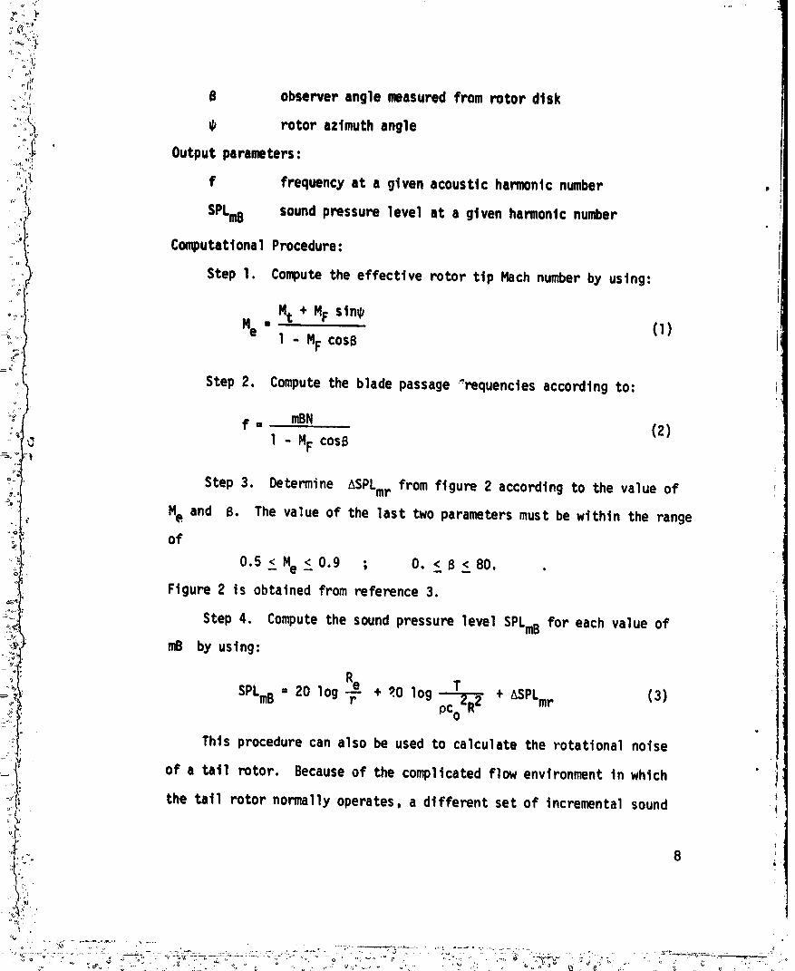
Computattona1 Procedure:
Step 1. Computethe effective rotor ttp Machnumberby using:
Mt + MF stn_"e "
1 - MF cosB
Step 2. Computethe blade passage"requenctes according to:
f . mBN (2)1 - MF cosB
:t
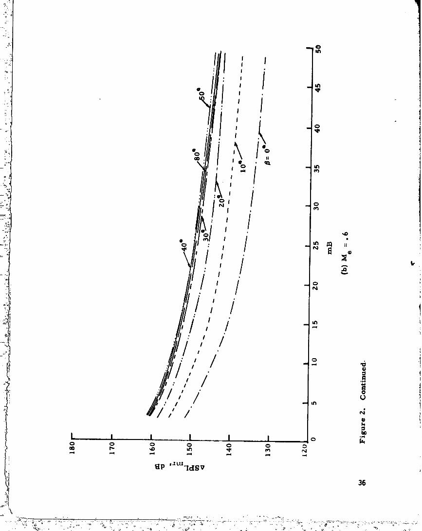
Step 3. Determine ASPLmrfrom ftgure 2 according to the value of
,. Me and B. The value of the last two parameters must be within the rangeof
0.5 <_Me <_0.9 ; O. < B <_80. .
Figure 2 ts obtained from reference 3.!
Step 4, Computethe soundpressure level SPLmBfor each value of
mB by using:J
Re
SPLmB- 20 log "F" + _.0 log _ + ASPLmp (3)
Thts procedure can also be used to calculate the rotational noise
of a tall rotor. Becauseof the complicatedflow environment in which
the tatl rotor normally operates, a different set of incremental sound
8
•D,_
%
1980007615-TSA10
pressure levels, _FLtr, should be determinedtn Step 3 using values of
ASPLtr provtded in ftgure 3. Thesevalues are basedon an assumedratio
of thrust to drag to radtal forces of 10:1:0 and a loadtng exponent
" n = -2.1 _. Figure 3 appltes for the tat1 rotor of a hovertng helicopter.
Accordingto reference 5, a htgh frequency loadtng exponentn of
approximately -1.85 can be used for tnfltght tat1 rotor rotational noise.
Hence, figure 2 maybe used for these latter cases. The difference in
the assumedvalues of thrust to drag to radtal force ratios between
figures 2 and 3 should be noted tn practical applications.
Rotational noise/compressibility-Induced proftle draq noise.- This noise
source is attributed to periodically fluctuating torque loads on a helicopter
rotor blade generally occurring in high-speedforward flight. The simplified
prediction procedure presented here is basedon the work of Arndt and Borgman
(ref. 6).Inputparameters:
c rotor blade chord length
Me effective blade tip Machnumber
Mdd dragdivergenceMachnumber
r distancefromsourceto observer
R rotorradius
Re effectiverotorradius
B observeranglemeasuredfromtherotordisk
Outputparameters:
• SPLmB componentsoundpressurelevelat givenbladeharmonic
frequency
g
v .. " . ,* • k. " -
1980007615-TSA11

_ '/T
'" '_,
_- Computational Procedure:
if'o _, Step 1. The effective ttp Hach number ts obtained according to
i_ equatton (1). If He ts less than or equal to Ndd, the compresstbtltty-:11 induced profile drag notse componentsvanishes. Proceed with Steps 2 and .
• 3 if Re Is greater than Hdd.
Step 2. Determine ASPLc from ftgure 4 by ustng values of roB, He ,
and 13. The range of He 'is restricted to
Mdd<M e <0.95 .
Step 3. Computethe compressibility-Induced proftle drag notse
componentby ustng the following equation:
ReSFLmB= 20 log _ + 20 log [(Me - Mdd) c/R] + ASPLc - 21,6 (4)
Thickness notse.- The method chosen here for the computation of helicopter
t:, blade thickness noise was developed by Hawktngs and Lowson (ref. 7).
input parameters:
B number of blades
C blade chord length
h blade thickness
He effective tlp Hath number
r distance from source to observer
R rotor radius
observer angle measured from the rotor disk
Output paramel_r:
SPLmB sound pressure level at a given harmonic frequency.
-'. 10
t,
1980007615-TSA12

:.... _ Computatlonalprocedure:
.... _ StelJ 1, [Jetermt,'.e ASPLT from ft£ure 5 accordtl_gto given values
i_::,:_, of roB, Me , and t_. The range of Me is confined to! _
il o.8__"e<-o.95 .q_
_'":_, Step 2. Determine _SPLK from figure 6 according to the hPrmontc
n_mber mB and the blade chord to rotor diameter ratio, c/D.
Step 3. C_mputethe soundpressure level for the thickness noise
componentby using the fo|lowtng equation:
SPLmE= 40 log He+2_ log R/r + 20 log h/c + 20 log B + L_SPLT + L_SPLK - .9
(s)In thts computational procedure, the curves tn figure 5 are computed
according to the Hawktngsand Lowsontheory wtth a value of c/D = 0.03.
The Incremental soundpressure level adjustment L_SPLK ts a correction
,, factor for tutors having different c/D values. Thts correction fa_or
is assumedto be independentof observer angle.
Interaction noise/blade and vortex interaction.- The computationof noise't'
resulting from the interaction of a helicopter rotor blade and a trailing tip
vortex is basedon the work of Wright (ref. 8). Thts noise mechanismis
present only for somehelicopter flight conditions. Figure 7 illustrates an
exampleof helicopter flight conditions where the wake t_aJectortes interact
wtth the rotor blades to producethe impulsive noise which ts typical of this
• noise component.
. Input parameters:
B numberof blades
Lo average blade 1t ft
11
"" '.":;,,_:_ " "' ..... ""__-_ " °"" 1980007615 TSA1

I
./
"_'i, N rotor speed, rev/sec
l r distance from source to observerT total thrust of rotor
ii _ observer angle measured from rotor disk '
_. AL Incremental ltft on blade owing to interaction
_o total disk azimuth angle, 360°
p atr densityOutput parameter:
SPLmB sound pressure level st given harmonic frequency
Computationalprocedure:
I Step l, Determine ASPLbv from figure8 for 31w'. w::L,,._ _
.. and A_I_o. The range of the aximuthratio given in f,fur_8 is
" 0.02 < A,/g.o < 0.05 .
" Step 2. Computethe sound pressurelevel for the blade-vortex
interaction noise by using the following equation:+
AL co_B) + 20 log T.N + ASPLbv+ 190.2 (6)SPLmB-20 (Fo
It has been found from experiencethat for the noise resultingfrom a
blade-vortexinteractionon the advancln_side of the rotor disk, a typical
value of the azimuthratio A_/_o is 0.05. The 11ft ratio AL/Lo varies
from about .15 for a conventionalblade (constantchord, lineartwist,
square tip) to about .07 for a blade with blade tip air injection. In
the presentcomputationalprocedure,valuesof the azimuthratio and the
incrementallift ratio are emplrlcallydetermined.
12
ii Interaction no!se/installatton effect.- Increased attention ts being
directed at subject of noise generated by the Interaction of a tuwbulent air-
stream with a lifting rotor. There are currently no verified prncedures avail-
able for the calculation of helicopter Installation noise.
BroadbandNoise
Broadband noise ts a complex noise source comprised of a number of diffe-
rent componepts. Current prediction techniques for boundary layer, turbulent
Inflow, and vortex Interaction effects need additional Investigation to provide
reasonable correlation with experimental d_ta. The recommendedprediction pro-
cedure is basedon a dimensionalanalysis approach. Contributions from various
:; components, as shown tn figure 1, are not explicitly Identified tn this
prediction procedure.
The recommendedrotor-generated broadband noise computation procedure is!t
:5 m based on the work of Lowson (ref. g), Hubbard (ref. I0), Schlegel (ref. II), v
:_ and Munch (ref. 12).
: . Input parameters:
" M Ab total blade area of the rotor
_'L averageblade lift coefficient
_i T total thrustof the rotor
VT rotor tip speed
r d_stance from source to observer
eI e,nglebetweennegativethrustaxisand linefromhub to
observer,deg.
13
'\
1980007615-TSB01

i I: o.,p.t,.r.,er,SPL1/3 one-third-octave band sound pressure level for the overall
contribution from all broadband noise components.
Computattona1 procedure:
Step 1. Computethe peak broadband noise frequency by using the
following equation*:
fp = -240 log T + 2.448 VT + 942 (7)
Step 2. Identifythe peak frequencywith a standardI/3-octaveband.
Step 3. Computethe peak I/3-octaveband sound pressurelevel by
using the followingequation:
VT 3 Ab
SPLI/3= 20 log (_) + I0 log _ (cos2 eI + .l) +Sl/3 + f(_L) + 130(8)
where SI/3 can be determinedfrom figure9. The lift coefficient
function, f(_L),for most helicopterswith _ _ .48 is I0 log (CL/.4).
Preliminaryexperi,entaldata indicatesignificantlyhigher valuesof"i
f(_L) for CL "".48. The normalizedspectrumfunction Sl/3 as shown
!'_ in figure 9 is developed by Schlegel (ref. 11).
Step 4. Compute the sound pressure level for all the other one-
third-octavebands accordingto equation (8) and figureg.
_.)i
:11 *This equation is dimensionallyincorrectand it is unlt dependent. For the: _,
i_i English system of units this equation should read:!,! f - ..240 loq T + .746 VT + 7B6 .> P
i
..o::,:. ,-,, ,.".. .: -° - ....... 1980007615-TSBO:

°_
APPLICATIONANDEVALUATION
_liI This section of the report Illustrates the use of the recommendedpredic-:_ . tton methods by numerical examples. In addition, an indication of parameter
_t sensitivity and the effect of variation in any empiricism are investigated.
The examples chosen represent a wide range of operating conditions and vari-
ables. The particular examples show how to apply the prediction techniques
and the corresponding agreement with existing experimental data. The first
examle specifically illustrates the calculation of rotational noise from the
main and tail rotors of a large hovering transport-type helicopter. The
second example illustrates the prediction of impulsive noise resulting fro_-j
blad_,/vortex interaction for a wind-tunnel model in a simulated rate of
descent. The calculation of high-speed impulsive noise is illustrated in the
' third example and compared with experimental wind-tunnel model data.
Example I
The noise from a la_je, hovering, single-maln-rotor helicopter can be
calculated using equations (2), (3), (7), and (8). Only rotatlonal and broad-
band noise componentsare considered for this example because the tip speed
is sufficiently low so Chat thickness and compressibility noise do not affect
the acoustic spectra. Since the hellcopter is hovering no blade/vortex inter-
action is as_-:medto occur. For the conventlonal type hellcopter, this pro-
cedure must also be repeated for the tall rotor and the results superimposed
on a frequency basis. The following infomation is required to predict
the noise:
15
1980007615-TSB03

Main Rotor Tail Rotor
, Ttp Mach number .6 .6
Rotor speed, rps 3.5 21.1
Blade radius,m 9.45 (31 ft) 1.52 (5 ft)
Observerangle, _, deg 5° 80°
Number of blades 5 5
Thrust,N 69420 (15,600Ibs) 5206 (1,170Ibs)
Blade area, m2 18.58 (200 ft2) 3.44 (37 ft2)
Air density,kg/m 3 I.228 _ I.228(.00238slug/ft_) (.00238slug/ftJ)
Observerdistance,m 61.6 (202 ft) 62.2 (204 ft)
Mean lift coefficient .438 .182
The tall rotor rotatlonalnoise and thrust is based on the assumption
i that the ratio of rotor blade thrust to drag is 10:1 and that the distance
from the tail rotor to main rotor is 11,Im. The radiusand Mach number
16

t at which the rotor forces are assumedto be concentrated is .9 of the
actual radtus.
The rotor noise for the example hovering helicopter ts composedof both• .! o
rotational and broadband components for the two rotors. The rotational noise
ts calculated first from equation (3) and figure 2. Values of the tip Mach
! numberare obtained by tnte_olatton In figure 2.
8.50 69420Rotational: = 20 log _ + 20 log
(1.228)(344)2(9.45)2 + ASPLmr
= 17.2 - 45.4 + ASPLmr
,_ = -62.6 + ASPLmr
='i fundamental frequency = NB = 17.5 Hz(1 - MF cose)
i
. Calculated, Experimental,
mB Frequency ASPLmr SPLmB SPLmB**
5 17.5 148.4 85.7 85.0
10 35.0 143.5 80.8 79.5
15 52.5 140.2 77.5 76.0
20 70.0 138.4 75.7 73.0
* From figure 3 for Me = .54 and B = 80°
** Data from reference 13, figure 17.
17
1980007615-TSB05

, )f
Tat1 rotor: = 20 log _-_ + 20 log- 520G(I.228)(344)2(I.-_)"_ �ASPLtr
• -33.1 - 36.2 + ASPLtr
- -69.3 + ASPLtr
.t
fundamentalfrequency= _(5=)(21.1). = 105.5 Hz;1-(0) cos 80
Calculated, Experimental
_SPLtr* SPLmB SPLmB**mB frequency
5 _J5 154.4 85.1 82
, 10 210 149.2 79.9 7Gt
15 315 145.9 76.6 7520 420 143.8 74.5 73
*From figure3 for Me = .54 and 6 = 80°.
_ **Data from reference13, figure17.
) Broadband:The rotor broadbandnoise is calculatedbased on equation(8). For
"t
the main rotor:
z208_3 [ 18.6. ]SPLI/3 = 20 Iog _3_[I+ I0 logL(61.g)Z(cos2 85 + .I) �$1/3+
1.438)+ 10 log _--- + 130.
=43.1 - 32.8 + $1/3 + .39 �130.
-- 84.5 + Sl/3
18
1980007615-TSB06

The rpectrumcorrection value, $1/3, is obtained from figure 9. Peak fre-
quencies for both main and tat1 rotors are calculated from equation (7):
fp = -240 log (69420) + 2.448(208) * 942
= -1162 + 509 + 942 = 289 Hz
fp = -240 log (5206.5) + 2.448(202) + 942L_
!_, = -892 + 494 + 942 = 544 Hz
The third octave frequency spectra for the b_oadbandnoise uses the above
information and is calculated below for both the main and tat] rotors. The
main rotor broadbandpeak frequency of 289 Hz fa]ls within a bandwhere the
center frequency is 315 Hz, therefore:
1/3 Octave $1 SPL1Center Freq. /3 /3
40 -19.5 64.8
80 -15.3 69.0
160 -11.7 72.6
315 - 7.5 76.8
630 -11.5 72.8
1,250 -12.1 72.2
2,500 -16.5 67.8
5,000 -17.0 67.3
10,000 -21.8 62.519
v
1980007615-TSB07

i :,,u o _}
_--.. .)
...,{,: !}-, 111
:.,:.:I Tall rotor peak frequency, fp 544 Hz, ales In a third octave band with acenter frequency of 630 Hz, therefore: i
. ". :ii" I13 Octave' Center Freq, $I13 SPL113
20 -29.0 56.1
40 -24.5 58.6
80 -19.5 63.6
160 -15.3 67.8
315 -11.7 71.4
630 - 7.5 75.6
I ,250 -11.5 71.6
2,500 -12.1 71.0
5,000 -16.5 66.6
10,000 -17.0 66.1 iiI
i_ID
DtscPete noise componentsat blade passage frequencies previously calculated " :-1i
,, may be combinedwith the one-third-octavebroadbandnoise levels by adding I1
the sound pressurelevelsin each I/3-octaveband. The calculatedvaluesare iJ
then combinedand shown in the followingsummarytable. The table is carried 1r,
out to a frequencywhere most discrete'datafor conventionalhelicopters
become less than the broadbandnoise.
iJ Ii 2o i

1/3-Octave Tat1 roto.r_ SPL Main rotort SPL Total, Exp. TotalCenter Freq Rot. S.B. Rot. ' B.S.' SPL (Ref. 13)
_ l l I I IN I m I ml lL ,,11 , , I , ' I I II
16 85.7 85.7 85
• 20 54.1 54.125
) 31.5 80.8 80.8 79.540 58.6 64.8 66.5
50 77.5 77.5 76
63 75.7 75.7
80 63.6 69.0 70.1 73
)i loo 85.1 8s.1i .
125 lk
t_: 160 67.8 72.6 73.8
200 79.9 79.9 76250
315 76.6 71.4 76.8 80.3 75
400 74.5 74.5 73 _500
630 75.6 72.8 77.48O0
1K
1.25 K 71.6 72.2 74.91.6 K2K
2.5 K 71.0 67.8 72.7
" Correlation of the calculated soundpressure levels and those flight test
measurementsin reference 13 indicate goodagreementto the fourth hamontc
for both the main and tat1 rotors.
' A sensitivity analysts of specific parameters tn the rotational and broad-
bandnoise componentsfor the previousexamplethatare dlfflcultto measure
experimentallyindicatesthata I0 percentvariationin: a) thrustwill
21

-_v_;_1.
: t, result tn approximately .9 dB change tn notse level and 10 Hz shift tn
_"_:-'i':_' broadband frequency; b) atr density wtll chanqe the level approximately .9
i i!:!;i_ ': dB; c)speed of sound wtll change the level approximately 1.8 dB and; d)
rotor speed wtll change the broadband level approximately 2.8 dE and shift
the center frequency 50 He.
Example II
Thts example Illustrates the use of the blade-vortex interaction equation !_!i
: (ea. (6)), as applted to a two-bladed rotor wind-tunnel model. The expert-
mental data used for correlation in this example are reported in reference 14.
The contribution fn)m the rotational and thickness noise components is not
affected by the periodic loading noise induced by the blade/vortex interaction
and is therefore not considered in this example. The necessary parameters
required to determine the discrete harmonics resulting from a blade/vortex
interaction and the specific values for the example are listed below:
•" Total rotor thrust, N 458.35 (103 lb)
Tip Mach number .433
Rotor speed, rps 22.75
Observer angle, deg 49°
Observer distance, m 1.02 (3.35 ft)
Forward speed, m/sec 21.3 (70 ft/sec)
Speed of sound, m/sac 344. (1130 ft/sec)
It is assumedthat the major contributionof the interactionoccursover
that portionof the azimuthwhich startswhen the vortexfirst interceptsthe
tip of the blade and the blade sweeps throughapproximately18°. The momentary
blade load disturbance, AL, caused by this interactionis assumedto be
Ill 22
,_.
' E ..... ........ _ -
]_UUU/D l _-/0 D 1 u

_ 20 percent of the load of one blade or 10.3 lb. The ms soundpressure i
il hamontc levels from equatton (5) and ftgure 8 are thereforet
I . SPLmB= 20 log (.2 cos 49) + 20 log (458.35)(22.75)(1.228)(344)3(i,02)..... + ASPLbv+ 190.2
! - -17.6 - 73.8 + ASPLbv+ 190.2
- 98.8 + ASPLbv
frequency, ASPLbv* SPLmB,dBr,B Hz (from eq (5))
4 228 -23.0 75.8
I0 455 -11.5 87.3
; 16 683 - 6.0 92.8
20 910 - 3.0 95.824 1138 - 1.7 97.1
t_., 30 1365 - 2.3 96.5',j
:_ _ 36 1593 - 4.5 94.3
40 18:70 - 9.5 89.3
44 2048 -22.3 76.3
* Fromftgure 8. _ = .05_o
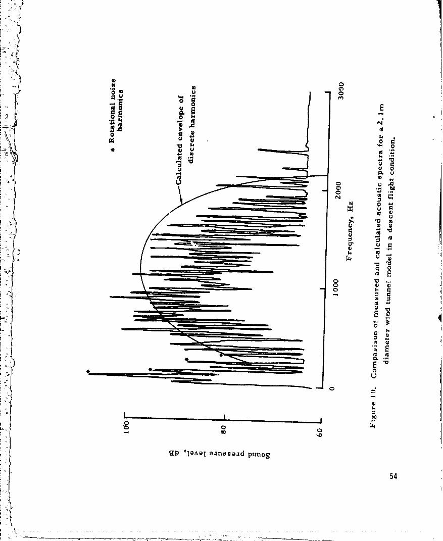
Thesecalculated hamonJcsmakeup an envelope ano _e superimposedon the
experimental data taken from reference 14 and s_owntn figure 10, The
agreementshownfn this figure betweentheory andmeasureddata is good,
that ts, the harmoniclevels and characteristic spectrum shapeare stmJlar.
The harmoniccontent occurring at the lowest blade passagefrequencies
is due to the steady rotational andblade thickness sources. The periodic force
fluctuation causedby the blade/vortex interactions do not affect these harmonics.
23

_:/T_;I,} Thts example illustrates the prediction and correlation of the htgh tip-
/l!:ti speed noise sources. Experimental data for thts example are taken from
• reference 15. These data were taken from a hovering 1/7-scale UH-1 rotor
operating at two thrust conditions. Comparisons of the calculated results
and the experimental data are given in figure 11 for two ttp Mach numbers.
The following information ts required for the calculations:
B =2
r = 3.14 m (10.3 ft)
B = 0°
T = 485 N, 676 N (109 lb, 152 lb)
Me = .9 (N = 47.2 rps, fo = 94 Hz)
Me = .8 (N = 41.g5 rps, fo = 84 Hz)
c = .0762m (.25 ft) v
R = 1.05 m (3.43 ft)gf
Mdd = .8 (fig. 15)
h/c = .12
Re = .945m (3.09 ft)
Numericalcalculationswill be made to computecompresslbllltynoise,
-- rotational noise and ftnally the contribution of thickness noise. These calcu-
lations are then compared wtth the measured data. The compressibility-induced
proftle drag noise is determined from equation (4) and figure 4 for Me = 9:
.934_ SPL = 20 log _ + 20 log [(.g - .8) .0762/1.05] + ASPLc - 21.6
= -10,4 - 42.8 - 21.6 + ASPLc = 74.8 + ASPLc
24
17,)/I
1980007615-TSB12

° ,_' r
!'_ _ .............. SPLmB,dB ....';{_i frequency, ASPLcmb az (fromeq. (3))
2 94 173. g g9.1
' 4 188 175.3 100.5
8 376 176 101.2
12 564 175.7 100.9
16 752 174.9 100.1
20 940 173.9 99.1
30 1410 170.2 95.4
These values are _hown in the lower portion of figure 11 as the square data
points.
The compressibility-induced drag noise calculated values for R = .8 are
, zero because the ttp Hach number is equal to the drag divergence Hach number.
Thickness noise values are similarly determined from equatfon (5) and
figures 5 and 6.
, SPLmB= 40 log (.g) + 20 log (-,_-_) + 20 log (.12) + 20 log (2) +
+ASPLT + ASPLK - .9
= -24.6 + ASPLT + ASPLK (Me = .9)
= -26.7 + ASPLT + ASPLK (Me = .8)
1
ii!
• 5_TSB13' °".... _ " 198000761

• T ............... - -._ ....... ,_ __ u _L L'
freq. ASPLK
mB Hz (for M-.8 & .9) ASPLT@MT"8 SPL,dB ASPLT@MT='9 SPL,dB• L l _ , L J
2 94 3.5 117.9 94.7 119.6 98.4
4 188 3.5 i22.1 99.6 119.6 104.1
8 386 3.4 123.9 100.6 129.7 108.4
12 564 3.2 123,2 99.7 131.6 110.1
16 752 3.1 121.7 98,1 132.4 110.8
20 940 3.0 119.6 95.9 132.7 111.0
30 1410 2.5 113.4 89,2 132.2 110.0
The rotor Is producing thrust and therefore a rotatlonal nolse is also
3 calculated. Thls Is done uslnq equatlon (3) and figure 2 for _p effectlve
_ tip Hach number of .72 and .81 (Hach number at assumedforce 1ocat_on .9R):,If
SPLmB= 20 lo9 _ + 20 log 485(1 228)(344)2(1.05) 2 + _SPLmr.
" = -10.4 - 50.4 + ASPLmr= -60.8 + ASPLmr
freq. SPLmB,dB SPLmB,dBmB Hz ASPLmr@Me='81 (from eq. (2)) ASPLmp@Me='72 (from eq.(2))
"_ 2 94 155.5 94.7 154.3 93.5
4 188 156.7 95.9 154.2 93,4
8 376 157.3 96.5 153.3 92.5
12 564 156.6 95.8 150.6 89.8
16 752 155.5 9_.7 !47.7 86.9
20 940 154.5 98.7 145.9 85.1
30 1410 152.4 91.6 142.3 81,5
26
] 9800076] 5-TSB14
I
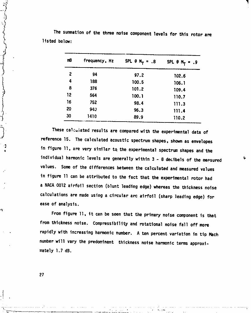
The summation of the three noise component levels for this rotor are
11sted below:
I mB frequency, Hz SPL @MT = .8 SPL @HT = .9
i ii m
2 94 97.2 102.6
4 188 100.5 106.1
t 8 376 101.2 109.412 564 100.1 110.7
16 752 98.4 111.3
20 94_ 96.3 111.4
30 1410 89.9 110.2
These calculated results are compared with the experlmental data ofreference 15. The calculated acoustic spectrum shapes, shownas envelopes
in figure 11, are very simtlar to. the experimental spectrum shapes and thet
Individual harmonic levels are generally within 3 - 8 dectbels of the meesured
values. Someof the differences between the calculated and measured values
in figure 11 can be attributed to the fact that the experimental rotor had
" a NACA0012 airfoil section (blunt leading edge) whereas the thickness noise
calculations are made using a circular arc airfoil (sharp leadtng edge) for
ease of analysis.
From figure 11, it can be seen that the primary noise component is that
from thickness noise. Compressibility and rx)tattonal noise fall off more
• rapidly with increasing harmonic number. A ten percent variation in tip Hach
number wtll vary the predominant thickness noise harmonic terms approxi-
mately 1.7 dB.
27
L
"' ° 1980007615-TSC01

CONCLUDINGREHARKS
Semi-empirical methods for the calculation of helicopter matn- and tall-
rotor notse have been presented. These methods represent, tn the author's
optnlon, the state of the art for semi-empirical helicopter notse prediction.
The methods have been presented tn such a way that solutions can be obtained
with the help of computer-derived graphs. Examples have been provided
Illustrating both the analysts procedure and the degree of agreement with
experimental results. Agreement of the analytical and experimental results
is generally good. The calculation procedures have been organized so that
as improvements are made, they can be easily incorporated in the general
_ calculation procedures.
] 9800076] 5-T$C02

:L°,_ REFERENCES
I. Sternfeld, Harw, Jr.; and Wtedersum, Carl W.: Study of Destgn Constraints_ _ on Helicopter Noise. NASACR 159118, July 1979.
_i 2. Hagltozzt, Bernard: V/STOL Rotary Propulsion Systems Nolse Prediction and
i ili!i Reduction. U. S. Dept. of Transportation. No. FAA-RD-76-49, May 1976.
3. Lowson, H. V.; and 011erhead, J. B.: Studies of Helicopter Rotor Noise.USAAVLABSTech. Report No. 68-60, January 1969.
4. Kasper, Pete;- K.: Determination of Rotor Harmentc Blade Loads from AcousticHeasuremen_s. :PSA CR 2580, Oct. 1975.
5. Levtne, Larr3; S.: An Analyttc Investigation of Techntques to ReduceTail Rotor Noise, NASACR 145014, July 1976.
6. Arndt, Rodger E. A.; and BargmanoDean C.: Notse Radiation from HelicopterRotors Operating at High Ttp Hach Number. American Helicopter Society,26th Annual Forum, June 1970,
7. Hawk4ngs, D, L,; and Lowson, H, V,: Tone Notse of Htgh Speed Rotors, SecondAero-Acousttcs Conf,, Hampton, VA, March 24-26, 1975, AIAA Paper 75-450.
8, Wright, S. E.: Discrete Radiation from Rotattng Periodic Sources. J. Sound: and Vlbratlon (1971) 17(4), pp. 437-498.
9. Lowson, H. V.: Thoughts on Broad Band Nolse Rad4atlon by a Hellcopter.Wyle Laboratories _JR68-20, 1968.
10. Hubbard, H. H.: Propel ler-Nolse Charts for Transport Airplanes. NACATN 2968,
11. Schlegel, Ronald G.; King, Robert J.; and Hut1, Harold: Hellcopter RotorNoise Generation and Propagatlon. USAAVLABSTech. Report No. 66-4,Oct. 1966.
12. Hunch, C. L. : Prediction of V/STOL Noise for Applications to CommunityNoise Exposure. DOT-TSC-OST-73-_), May 1973.
13. Pe,qp, Robert J.; Henderson, Herbert R.; and Htlt_n, Davtd A.: Results ofthe Flight Noise Measurement Programs Ustn9 a Standard and Modtfted SH-3AHelicopter. NASATN D-7330, Dec. 1973.
14. Pegg, R. J.; and Whtte, Richard A., Jr.: SomeReasured and Calculated Effectsof a Ttp Vortex Hodtftcatton Devtce ore Impulsive Noise. AIM Fourth Aero-acousticCo.f., Atlanta, Cd_,AIAA Paper No. 77-1341, 1977.
"_1 15. Boxwe11, D. A., Yu, Y. H. ; and Schmttz. F. H.: Hovertnq Impulsive Noise -
-!!t SomeNeas,red and Calculated Results. NASACP 2052, PL. 1, Hay 1978,?9
"",-_" "-_"- ' - ' ...... " ..... - ....."....,"....." "" " " '" ....'" " 1980007615-TSCC,.-,wa,

F
16. Lynam,E. J.; and Webb,H. A.: The Emission of Soundby Atrscrews.Aeronautical ResearchCouncil, R&M624, March1919.
17. Bryan, G. H.: The Acousticsof MovingSourceswith Application to Atrscews.Aeronautical ResearchCounctl, R&M684, lg20.
• J18. Guttn, L. J : Onthe SoundFteld of a Rotating Propeller. NACATM 1195,1958.
19. King, Robert J.; and Schlegel, Ronald G.: Prediction Methodsand Trendsfor Helicopter Rotor Noise. CAL/AVLABSThird Annual Symposium,June 18-20,1969.
20. Hubbard, Harvey H.; and Regter, A. A.: Free-SpaceOscillating PressuresNear the Tips of Rotating Propellers. NACATR 996, 1950.
21. Garrick, 1. E.; and Watktns, C. E.: A Theoretical Studyof the Effectsof Forward Speedon the Free-Space.Sound-PressureField AroundPropellers.NACATR 1198, 1953.
22.Watklns,C. E.; and Durllng,B. J.: A Methodfor Calculationof Free-SpaceSoundPressuresNeara Propellerin Flight,IncludingConsiderationof theChorclwlseLoading.NACATN 3809,1956.
23.Hosler,R. N.; and Ramakrlshnan,Ramanl: HelicopterRotorRotationalC Noise Predictions Basedon MeasuredHigh-FrequencyLoads. NASATN D-7624,t Dec. 1974. _
24. Sadler, S. Gene: and Loewy, Robert G.: A Theory for Predicting the Rota-tional and Vortex Noise of Lifting Rotors tn Hover and FonvardFlight.NASACR133_, Hay 1969.
,!
25.Wright,S. E.: SoundRadiationfroma LiftingRotorGeneratedby AsynlnetrlcDiskLoading.J. Soundand Vibration(1969),9(2),p. 223-240.
26. Lowson,M. W.: The SoundFieldfor Singularitiesin Motion. Proceedingsof the RoyalSociety,A. vol.286,1965.
27. Lowson,M. g.;and Ollerhead,J. B.: A TheoreticalStudyof HelicopterRotorNoise.J. SoundVibration,9(2),pp. 197-222,(1969).
' 28. Sternfeld,Harryet al: An Investigationof Noise_neratlonon a Hovering;:" Rotor,Part II. Boeing Company-VertolDivision.
:3 29.Lawton, B.g.: SubjectlveAssessmentof SimulatedHellcopter-Blade-SlapNoise. NASATN D-8359,Dec. 1976.
:: 30. Leverton, John g.: Helicopter Noise - Are Existing MethodsAdequateforRating Annoyanceor Loudness?AmericanHelicopter Society J., vol. 19,no. 2, April 1974.
3O

l
°:_" 31. Cox, C. R.: Rotor NotseHeasurementstn WtndTunnels. ProceedingsThtrdCAL/AVLABSSymposium,Aerodynamicsof Rota_ Wtndand V/STOLAircraft,vol. 1, June 18-20, 1969.
32. Powe11,ClemensA.: A Subjective Fteld Study of Helicopter Blade-SlapHotse. NASATH 78758, July 1978.
.
33. Leverton, JohnW.; Southwood,B. J. ; and Pike, A. C.: Rating HelicopterNoise. Helicopter Acoustics, NASAConferencePubltcatton_ 2052, Pt. [],
1978.
34. d'Ambra, F. and Daunongeot,A.: Annoyanceof Helicopter ZmpulstveNoise.Helicopter Acoustics, NASAConferencePublication 2052, Pt. 1t, Hay 1978.
35. Sakowskl, P. C.; and Charles B. D.: Notse HeasurementTest Results forAH-LGOperational LoadsSur_ey. NASACR159036, June 1979.
36. Ernsthausen, E. W.: The Sourceof Propeller Noise. NACATN 825, Hay 1937.
37. Ernsthausen,E. W.: Znfluence of AerodynamicCharacteristics on Sound-Blade and Radiating Powerof an Aircraft. Akusttcshe Zettserrtft,vol. 6, pp. 244-262.
38. Demtng,A. F. : Notse from Propellers wtth SymmetricalSecttons at ZeroBlade Angle. NACATN 605, July 1937.
,_ 39. Dtprose, K. V.: Some Propeller Notse Calculations Showtngthe Effect ofThickness andPlanfo_n. Technical Note No. HS 19, Royal AtrcraftEstablishment, England. V
40. Bt111n9, H.: HodernAeronautical Acoustics. AVAHonographsR., HAPVolken-rode Reports and Translations No. 960, July 1947.
¢
41. Arnoldt, R. A.: Propeller Notse Causedby Blade Thickness. Report R-0896-1,United Atrcraft Corporation, Jan. 1956.
42. Farassat, F.: The Acoustic Far-Field of Rigid Bodies tn Arbitrary Hotton,J. Soundand Vibration, vol. 32, p. 387°402, 1974.
43. Landgrebe,Anton J.: The WakeGeometryof a Hovering Helicopter Rotorand Its Influence on Rotor Performance. 28th Annual National Forumof theAmertcanHelicopter Soctety, r4_y1972.
44. Sadler, S. Gene: DevelopmentandApplication of a Hethod for Predicting• Rotor Free HakePositions Rotor Free WakePositions andResulting Rotor
Blade Air Loads. Vol. 1 - Hodel and Results. NASACR 1911, Dec. 1971.
45. Johnson,H. Kevtn: Developmentof an ]mprovedDestgnTool for Predictingand Simulating Helicopter Rotor Notse. USAAHRDLTech. Report No. 74-37,
o_iI June 1974.
_ 31
" ................ "..........."................... 1980007615-TSC05

46. Halwes, Dennis: Fltght Operations to Minimize Helicopter Notse JointSymposiumon Environment Effects on VTOLDesigns. AHS, AIAA, U. ofTexas, Nov. 1970, Preprtnt No. SW-70-7.
l 47. Heyson, Harry H.: NomagraphtcSolution of the MomentumEquation forVTOL-STOLAircraft. NASATN D-814, April 1961.
, 48. Leverton, John W.: Helicopter Noise-Blade Slap. Pt. 1 Review and Theoret-Ical Study. NASACR 1221, October 1968.
49. Widnall, Shetla: Helicopter Noise Data Due to Blade-Vortex Interaction.J. Acoustical Society of America, vol. 50, no. 1, (Part II), 1971.
50. Padakannaya, Raghuveera: The Vortex Lattice Methods for the Rotor-Vortex° Interaction Problem. NASACR 2421, July 1974.
51. Ftlotas, L. T.: Vortex Induced Helicopter Blade Loads and Noise. J.Soundand Vibration, vol. 27, no. 3, 1973.
52. Tangler, James L.; Wohlfeld, R. M.; and Mtley, Stan T.: An Experimental _;Investigation of Vortex Stability, Tip Shapes, Compressibility and Noise
!_ for Hovering Model Rotors. NASACR 2305, Sept. 1973.!!:] 53. Tyler, J. 14.; and Sofrtn, T. G.: Axial Flow CompressorNoise Studies.
TRANSSAE, 1961, pp. 309-332.
t_ _ 54. Bran_vell, A. R. S.: Aerodynamic Interference of Helicopters. J. Soundand Vibration, vol. 3, no. 3, May 1966.I:.t
55. Pegg, R. J. ; and Shtdler, P. A.: Exploratory Wind-Tunnel Investigationof the Effect of the Main Rotor Wakeon Tail Rotor Noise. HelicopterAcoustics Specialists Symp., Hampton, VA, Hay 1978.
56. Sharland, I. J.: Sources of Noise in Axial Flow-Fans. J. Sound and. Vibration, vol. 1, no. 3, pp. 302-322, 1964.
57. Curle, N. : The Influence of Solid Boundaries on Aerodynamic Sound.Proc. of the Royal Society, A-231, 1955.
58. Lowson, M. W.; Whatmore, A. R.; and ghttfteld, C. B.: Source Mechanismsfor Rotor Noise Radiation. NASACR 2077, Aug. 1973.
59. Kemp, N. H.; and Sears, W. R.: The Unsteady Forces Due to Viscous Wakesin Turbomachtnery. J. Aeronautical Sciences, vol. 22, no. 7, pp. 478-483,July 1955.
60. Brown, David; and (Jllerhead, J. B.: Propeller Noise at LowTip Speeds.AFAPL-TR-71-56. 11)71.
61. Bull, 14. K. ; Wtlby, J. F.; and Blackman, D. R.: Wall Pressure Fluctuationsin Boundary Layer Flow, and Responseof Stmple Structures. SouthamptonUniv. Report AASU243, July 1963.
32
_: 62. Clark, Davtd R.: CanHelicopter Rotors be Oestgnedfor LowNotse and HtghPerformance_ NtS 30th Annual Forum,Washington,May1971, PreprtntNo. 803.
63. Yudtn, E. Y.: On the Vortex Soundfrc_ Rotattng Rods. NACATM 1136,1947.
(33
i
1980007615-TSC07


,, ' I
!, • ,I I ,
_11 ' I"11 I I
' o _I I .
•-i!, ,%1_/:i . I " l
• i / :• i i
|l
? '1
i .- II
? i: . . I
cp
mI'/," /
I I I I I I o0 0 _ 0 0 C3 o t
_p "ttu--ic[SV
,. 3S
" -".,-:"..... .__-- " -.... :- ..... .j/-:_-_:-_--:"" _ -.-_.... "... .. :'. : " _.L • . " _ , _. ' • '_ " "' _" " •.. " ..........
1980007615-T8009

] 980007615-T801 ]

_IP 'aw-idg v: 38
J
1980007615-TSC12


40
1980007615-TS014

",_ " • _:.., 4,' ,, ',., .,,'_ _. L, " " " ' " ....... _,_ _, . ,_ . ..... ::-: " " :" ...... ";""_',"_-'-_ '_'------'-o.... ..
1980007615-TSD01

l
_i 42
1980007615-TSD02


1980007615-TSD06

',_ _IP "L lclSv_* 47
_': L,I z.,_.;,. •..., • .... . . . .. Li-_-_._-.-.__ L. .... . ; ' ...... ......... •
1980007615-TSD07


0 0 0 0 0 C__ N _ 0 0 0 0
! 49 _P *'L"_d_Vl
'b-__ • ,.=.-__,_,... .:. , ;, ___. , - ................. ....... .... , -
1980007615-TSD09

_ SO
...... .. ....... . ..... .. _...... _.:....._.:..:._.__!:±)_., ...... , . ..,_
"198000Z_'1_-TSD'I0

z
51

5_
_t
,_ ,.+. pl "---+-++ ,, _+-. /- .._" + :+++.+........ + ...... +++........ -:_++._ + + ...........
"_9800076"_ 5-TSD12

e ,,
._, 0 _ I I w _ i i ! I I I ! !
h i
_ -10
t
-20 -
t.
" -30 -
,: _
,_ ' I I I I I i I I I I I II I I I I I 2 4 8 16 32 64 128
32 16 8 4 2
,f
BAND CENTER FREQUENCY RELATIVE TO f
BAND CENTER FREQUENCY, BAND LEVEL
; 1/32--29.0 z--ll.l/t6 : -z4.s 4 =-IZ.l
1/8 = -19.5 8 - -16.5
1/4 ---15.3 16---17.0
1/2 - -11.7 32 = -21.8
1 : -_.5 64 = -26.4
i- Figure 9. Normalized rotor broadband noise empirically
determined spectrum shape.
53 _
o i
1980007615-TSD 13
B[P 'IO^al_an_Baad punoS
I,
1980007615-TSD14

e_"
_- _ Compressibility
_ O Thickness
!_ G Rotational
" ---- Calculated total
IZO--
m e = • 9 I Experimental data points(ref. 15)
1llC" _ _ - I )- ' ' _
m /c,_, <
100- _ ,- [I [
° im90-
I-i0.,
II0 --0 m =.8
e
_" ---" r--- ---X ,_loo - f "-'x_...._>..."'4
d
• 90 " Ill[1
80 J ' ' I I I [" ' •0 5 I0 15 ZO Z5 30
mB
Fisure I I. Comparison of calculated and experimental inplaneacoustic data for a lifting, hoverin 8 rotor.
1980007615-TSE01
56
"_:'°" "" " ' _ ' "'-:_ ......_....... '_"............"" '""......1980007615-TSE02_:""

_ 1_980007615_TSE04

Figure 15. Drag divergence Mach number as a
function of tip thickness for typical
airfoils used in helicopter rotors.
59
!
, J • ,
1980007615-TSE05

160 -- e= ot k = .04'i
150 1.0 _..__
|_ .
=' _ 1 30120
II0 b. Effect of Mach number i
140- O= Op M = .8 _.
II0
100 -
90 I I I I I i I I I i0 4 8 12 16 20 24 28 32 36 40
mB
a. Effect of blade slenderness
Fisure 16. Thickness noise acoustic spectra shape as a fL,t_ction ofMach number and blade slenderness.
' 60
1980007615-TSE06

Blade
Vortex core
b. Parallel blade/vortex interaction : affects a large portion
of the lifting surface for a relatively short period of time.
t Rotor Blade
_".. Vortex core
" a. Perpendicular blade/vortex interaction: affects a smallportion of the lifting surface for a relatively long periodof time.
Figure 17, Schematic of blade/vortex interactions,
61

63
1980007615-TSE09


'1
APPENDIXA
PERIODICNOISE
Rotational Notse
The contribution to rotor and propeller dtscrete notse produced
by rotattng blade forces {thrust, torque, coning) ts called rotational
notse. This noise ts generated by both the aztmuthally uniform steady
and nonuniform(periodic) forces acting on the blades. Becausethe
nonuniformblade forces are harmonic in nature, they are frequently
referred to as blade-loading hamontcs. Theseforces are the source
strength of the acoustic dtpole portion of the solutton to the wave
equation. Rotation of the blades producesmovementsuccessively toward
4. and awayfrom the observer, thus introducing effects due to a vawtngf
Doppler frequency shift. Thts modulatedDoppler effect causeseach
loading hamontc to producemore than one soundharmonicin the stationary
system. The level of each soundhamontc ts thereby the result of the
contribution of manyloadtng harmonics. The periodtc repetition of these
forces at multiples of the blade passagefrequency results tn a dtscrete
frequency acousttc spectrum.
l" The analytical approachpresented fn thfs report ts basedon the
well-known compactsource theow, In recent years, moresophisticatedf
theortes for rotating blade noise from noncompactsourcedistributions
have been developed. These latter theortes require extensive computer
c_pabtltty andwt11 not be treated tn this report,
A-1
.... - " 1980007615 TSE i"

'_! Steady loadtng theory.- The earltest attempt to fomulate a theory
l of propeller acousttc radiation appears to be that of LynamandWebb
_ (ref. 16), who recognized that the rotating blades would cause both a
i- pertodtc ,w)dulattonof the flow through the disk and a correspondingacoustic disturbance at large distances. LynamandWebbmodeledthe
action of the blades by a continuous rtng of stationary sources and)
another rtng of sinks, wtth an arbitrary axial displacement; and _lter-
native approachwas tried by Bryan (ref. 17) who soughta solution for the
soundfield of a point source tn circular motion. Bryan's paper is
interesting as an early, though unsuc:essful, exampleof the retarded-time
approach.
i_ Neither of these papers predlct_'1 the absolute amplitude for the_) radiatedsound,and it was left.for Gutln(ref.11")to showthat,within
the frameworkof linearacoustics,the steadyaerodynamicforceson the
: rotating blades could be represented by acoustic doublets which are a
function of the torque and thrust of the rotating blades. This develop-
ment is limited to a hovering helicopter rotor, and the approximations
limit the accuracyof the calculations of noise to the fundamental and
first few harmonicsin the far field. Gutln's formulation for the
rotationalnoiseIs givenby equation(A-l) _,
iPml=_mBOIT cose1 " _e I JmB(mBMe stne1) (A-l)L
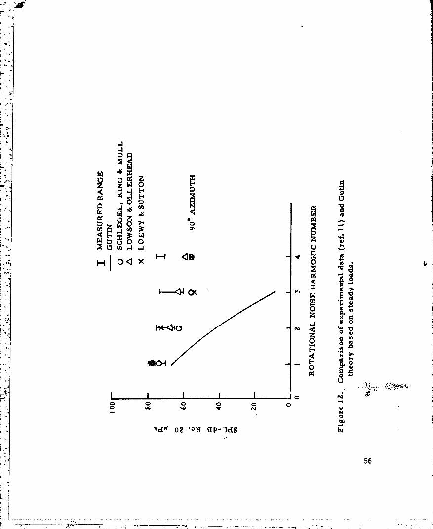
A comparlsonbetweenthe theoreticalresultsgivenby thismethodand ii
experimentaldatafora hoveringhelicopterrotor(ref.19)is shown
A-Z
............. '.... " ..... ' °-- ...... " " .... " 198000761"..... 5--S--TE12_

• in figure 12. The comparisontn figure 12 ts typical, tn that Guttn's
approachts usually accurate in predicting the fundamental blade passage
frequency soundpressure, but underestimates higher harmontcsound
pressures. The Guttn theory, using steady loads as inputs, ts useful
for predicting the low-order pressure harmonics that are most significant
for structural problems, but is not adequate for predicting the higher
order pressure harmonicsthat are most significant for subjective
reaction.
Gutln'sworkw _ extendedby Hubbardand Regler(ref.20) to deter-
mine theamplitudeand dlrectlvltyat pointsas closeas one-chord-width
froma propellertip. Severalparameterswere analyticallyinvestigated,
and comparlsousbetweentheoryandexperimentwere shownto be adequate
for tipMachnumberslessthanone. GarrickandWatklns{ref.21)
furtherextendedGutln'stheoryto includetheeffectsof forwardaxial
speed{verticalclimbcondition).They synthesizedthe soundfield
usln_the pressurefieldof a concentratedforcemovinguniformlyat
subsonicspeeds. The soundfieldis givenin termsof an integralover
the rotordiskand,usinga simplifyingassumption,overan effective
ring. Eachintegralgivesexpressionsforboththenear-fieldand the
far-fieldsound. The effectiveringexpressionfor the far-fieldcase
{eq.(38)in ref.Ill)is=
" ipml = men I T /HF c°sel (meMesinO1;o" '-, )
_I Resultsfromequation(A-2)fortypicalcasesshowthatthe directionof' maximumnoiseshiftsrearwardas forwardspeedis increased.
:, A-3
t.
4
1980007615-TSE13

'}
_!i Watktns and Durllng (ref. 22) extended the work of Garrtck and
L Wetktns to demonstratethe Importanceof spanwtseand chordwtseload
_11 distribution on the harmontcdistribution as well as on the overall
noise levels. The effect of the chordwtsoloadtng distribution ts of
primary importance.
Ftgure 13 presents a comparisonof typtcal measuredand calculated
rotational noise spectra basedon a measured40 percent chordwtse-
integrated, differential blade-loading spectrumand three different
assumedchordwtse-loadtng distributions (ref. 23). It can be seen that
all of the distributions provide similar agreementat low frequencies;
however,as the harmonicnumberIncreases the results begin to dtverge.
In a meJortty of case studies, the point loadtng distribution provided
,_ the _est agreementbetweencalculation and measurement. The rectangular
distribution al_ays provided poor agreementwhile the sawtooth distribution
(which should be a more realistic distribution) provided better agreement.
"" The exactshapeof the chordwlse-loadlngdistributionis particularly
importantat frequencieswherecompactsourceassumptionsbeginto i
breakdown. However,in mostof thecasesstudied,thisassumptionwas
not violatedand the pointloadingdistributionwas adequate.The gener-
allygoodagreementbetweenthemeasuredand calculatedrotationalnoise,
basedon loading measuredat eighty percent span, suggests that the it
aerodynamicloadingIs representativeof theentirerotor. _
Unstead_loadingtheory..-A techniqueForobtainingsolutionsto the
rotationalnoiseproblemwhenthe bladeloadsare unsteadywas advanced
by Schlegel,King,andMull in referenceIf. Thistechniqueresultedin a
t_ _' A-4
'--"_I
1980007B15-TSE14

I:
numerically tntagreted solutton whtch accounted for nonuntfom spamrlse
_ pressure dtstr|buttons on the blade. Their chordwtse pressure dJstrtbu-
tton was a rectangular pulse whose amplitude depends on the rotation
angle 9t. Better correlation wtth experimental data ts obtained vlth
thts analysts than wtth that of Guttn. The basic limitation to this
solutton is that higher harmonic loadtng data (m > 30) were not available.
A stmtlar solutton was presented by Sadler and Loew (ref. 24).
The rotational noise analysts of Wright (ref. 25) ytelds a far-field
sound pressure relation which is based on both steady and fluctuating
thrust and torque values in a manner stmtiar to that of reference 11.
Blade loadtng ts assumedconcentrated at one radial position. This
analysts provides excellent insight into the modal development of rota-
tional noise and a good basic understanding of the mechanismof noise
generation due to a rotational pressure fteld.
The more widely used prediction technique for rotational noise is
., that derived by Lowson (ref. 26). He showedthat the far-field sound
of a kotnt force tn arbitrary motion was given by:
o xt " Yt I')Ft + Ft aMr'l
= where Ft represents the componentsof the point force, _nd Mr ts the
°" componentof the relative Hach number tn the direction of the observer.
Observer and source locations are ^, and Yt' respectively, and terms
_ like ;,iF4 are inner products. Ba_ed on equation (A-3) a technique
was developed for calculating the rotational notse, using the rotor
A-S
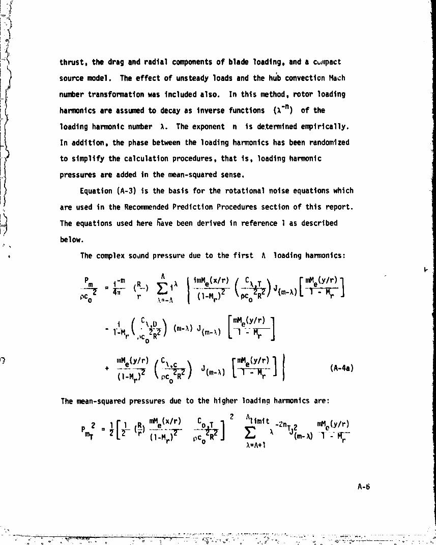
l_:I] thrust, the drag and radtal components of blade loadtng, and a c_l_act
source model. The effect of unsteady loads and the hl_b convection Hath
number transformation was tncluded also. In thts method, rotor loadtng
harmonics are assumedto decay as tnverse functions (X"n) of the
loadtng harmonic number ).. The exponent n ts de.retained empirically.
In addition, the phase between the loading harmonics has been randomized
i to stmpltfy the calculation procedures, that ts, loadtng harmonic
pressures are added tn the mean-squared sense.
Equation (A-3) is the basis for the rotational noise equations which
are used tn the RecommendedPrediction Procedures section of this report.
The equations used here h'avebeen derived tn reference 1 as describedbelow.
, The complex sound pressure due to the first ^ loading harmonics:
k
h { tmMe(x/r ) n_le(y/r)
Pm t "m (R_):_t_ -r=N-,j_.._ cl ;£o_I
" 1-.,. J(_-,)L1-_j
'_) "Mely/r) o"" L-l-_-_Fr-J_'mMe(ylr)1 ICl'"d_ (c_,_+
The mean-squared pressures due to the higher loading harmonics are:
roMe(X/r) C_12 Altmtt -2nTJ_m .fie(Y/r)oOo.-,z:_k=^+l
A-6
1980007615-TSF02

J _ 7
:G
•_ A1{rott
_o + _ _"2nT aE(n_) mHe(Y/r)l.Hr (A-4b)
_ii ),-^+1 A
' . ½[_ (_) mile(Y/r) (_)]CoO 2 I _'t _m- ruNe(Y/r)Pm0 "(1 - "r ) . )"2nOCm')')2J__X) 1 - Hr),=^+1
^1trait [m.ely/r)lI).-^+1
i
and_ltmtt
mc (l"Hr)2 (Co(: 2-, p_c-_)] _ _''2nc "](m-),, C_J!:,, _-A+I
AIImi t
"2no 2 [ nfqe(Y/r) ] I1.Hr',I +I: ', ,'(.,.,,) (,-4,,)i.." X=A+I
Equations (A-4a) through )A-nd) are then added tn a mean-squaredsense
pm2 2 + pn2r + Pn_D + Pm_ (A-S)= Pm ),<.A ),>A _A _>A
I The unsteadyforces acttng on a rotor blaCe comefrom manymechanisms;rotor/rotor wake Interaction, atmosphericturbulence, blade mot{on, and
t " atrfotl characteristics, amongothers. An analytical methodthat canaccurately predtct the combtnedeffect of all the sourcesmentionedabove
1 ts stq11 beyondthe present state-of-the-art.,v
!
i. A-7.__ •
o .:._ - - u " o - o o = o o _ . _. o ,.',,u.,... " _ ._ ' o., ' _ •
_ ooooo_ .. ......... o ........ ,... _ ..9_80007615°-° ..... °...... ........... I -TSF03
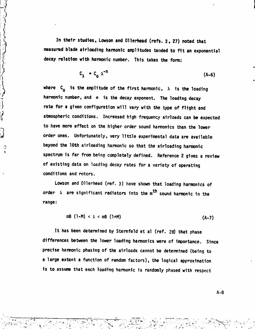
In thetr studies, Lowsonand 011erhead(refs. 3, 27) noted that
measuredblade atrloadtng hamonic amplitudes te,ded to fit an exponential
:, decay relatton with harmonic number. Thts takes the form:
t I C_ - Co X"n (A-6)!1
\ where Co is the amplitude of the first harmonic, >, is the loading_* harmonicnumber,and n is the decay exponent. The loading decay
;:_ rate for a given configuration wtll vary with the type of f11ght and
!_ atmosphericconditions. Increased high frequency atrloads can be expected7
to havemore effect on the higher order soundharmonicsthan the lower
order ones. Unfortunately, very little experimental data are available
,_ beyondthe lOthairloadlngharmonicso thatthe alrloadlngharmonic
' spectrumis far frombeingcompletelydefined. Reference2 givesa review
of existingdataon loadingdecayratesfor a varietyof operating
• condltlonsand rotors.
LowsonandOllerhead(ref.3) haveshownthatloadingharmonicsof
order X are significantradiatorsintothemth soundharmonicin the
range:
mB (l-M)< },< mB (l+M) (A-7)
It hasbeendeterminedby Sternfeldet al (ref.28)thatphase
differencesbetweenthelowerloadingharmonicswere of importance.Since
precisehamonic phasingof theairloadscannotbe determined{beingto
a largeextenta functionof randomfactors),thelogicalapproximation
is to assumethateachloadingharmonicis randomlyphasedwith respect
A-8
't_,
_Ii to the others. Stnce thts assumptionts not necessarily true for a
, spectftc situation, relative phasing error betweenloadtng harmonics
could account for the randomphastng, Lowson(ref. 3)* adjusted the
|oadtng exponentby adding .5. Hoster's data (ref. 23) substantiates
• randomphastngtn a band+ 40 degrees about O, wtth the exception of the
very lowest hamontcs where more prectse phase tnfomatton seemsImportant.
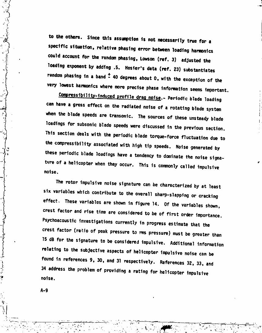
Compressibility-Induced proftle drag noise.- Periodic blade loadtng
can have a gross effect on the radtated notse of a rotattng blade system _
whenthe blade speedsare transonic. The sources of these unsteadyblade
loadtngs for subsonic blade speedswere discussed tn the previous section.
Thts section deals wtth the periodic blade toque-force fluctuation due to
the cmpresstbtltty associated wtth high ttp speeds. Notse generated by
these periodic blade loadtngs have a tendency to dominate the noise stgna-t
ture of a helicopter whenthey occur. Thts ts commonlycalled |repulsive
noise.
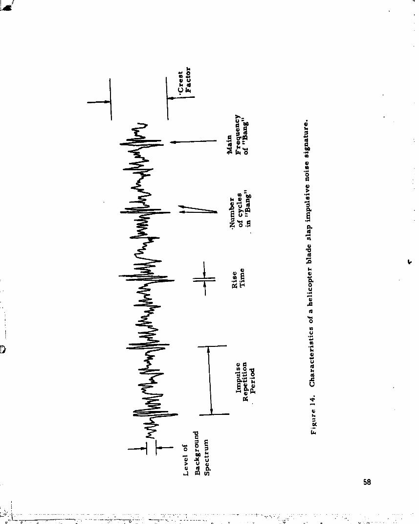
The rotor impulsive noise signature can be characterized by at least
stx variables which contribute to the overall sharp-slappfng or cracking
effect. These variables are showntn figure 14. Of the variables shown,
crest factor and rtse ttme are considered to be of first order importance.
Psychcacousttcinvestigations currently tn progressestimate that the
crest factor (ra_.to of peakpressure to ms pressure) mustbe greater than
15 dB for the signature to be considered Impulsive. Additional Information
relating to the subjective aspects of helicopter Impulsive noise can be
found tn references 9, 30, and 31 respecttvel.y. References 32, 33, and
_ 34 address the problemof providing a rating for helicopter Impulsive
noise.
A-9
....o ............ . "" 1980007615
_;L.
)
There ts a substantial tncrease tn the tmulslve notse of the rotor
as the advancing ttp speed goes above Mach 0.7. Since aerodynamic compres-
sibility effects such as the appearance of oscillating shock waves on .
the blades also beco_ |mportant tn thts ttp speed range, thts is called
compressibility noise. From the acoustic point of view, the thickness
and loadtng noise also show a stmtlar behavior in both the increase of
noise level and the dtrocttvtty pattern. However, recent studtes by
Boxwell, Schmttz arid Yu and also by Hansonand Ftnk have shown that the
nonlinear effects, resulting from the quadrapole source term tn the
governing acoustic equatton of Ffowcs Williams and Hawktngs, may be
also important in the calculation of compresstbfltty noise.
The highly directional characteristic of a_vanctng blade impulsive
, noise can be sho_n theoretically from Lowson's (ref. 3) equatton where
' the distance to the observer ts modified by a Machnumber correction.
This effect becomesof greater importance with increased harmonic number,
and has been identified expertmen_lly by Cox (ref. 31)in full-scale
wind-tunnel tests. Results from a recent flight investigation (ref. 35)
tndtcate that at an atrspeed of 130 knots, a region on the advancing
side of the rotor disk extending from 75 percent radius to the blade ttp
was experiencing somedegr#e of shock phenomena. Thus, while there ts
| an acousttc source effect at htgh ttp speeds whtch is partially responslble
for the generation of impulsive noise, the advancing blade tip Mach number,
which is a function of aircraft forward speed, accounts for the highly
directional character of thts type of nolse. Arndt and Borgman(ref. 6)
have presented an expression showing the effect of compressibility drag
:_t A-IO
_",- "" ........"",--_-._-....°°--o,_'. ,-o_._.'_°° _"".,..._. .. _,_ o"._: °"_," ""°"_°" :_ _° " :_"_"".... 1980007615-TSF

on the Impulsive notse as:
2' "o R c
• 4. 2im O0
Besides aircraft configuration parameters, this expression ts also
;_ , and the azimuth angle,a function of tncrementel drag coefficient, i_do• At, over which the MachnumberIs greater than the drag divergence 14ach
number,Mdd. Figure 15 showsthe variation of Mdd for typical helicopter
alrfoI1 sectlons. Equatlon (A-8) was derived from the basic rotatlonal
noise equations wlth only the drag ten, being considered.
lii ThicknessNotse
Blade thickness noise ts due to the volumedisplacement of the air
___ surrounding the blade, as tt movesthrough the atr. This notse ts
strongly directional tn the plane of rotation. ObservedsoundradiationJ,
_ from helicopters tn htgh speedforward fltght suggests that as the blade__.,r
tip advancesa strong pressure pulse ts generated. The notse from thts
source Increases raptdly with advanctn{ ttp Hachnumberand becomes
considerably stronger than the rotational notse components.
_, Ernsthausen(refS. 37, 38) using primarily an experimental analysis,
studted the characteristics of thickness noise. He emphasizedthe pre-
dominanceof h|gher hamon|cs at blade ttp Hachnumbernear 1.0. Demtngt
(ref. 38) performedexperimental and theorottcal work with syMetrical
bZadesecttons operating at zero angle of attack and developedthe f|rst
A-11
I)4 4
i vvvvv--_-- --

,F
L_ theory for thickness noise. The development of this theory follows much
/_, the same procedures as (;uttn's rotational noise work, however, hts
}_! analysis is essential for noncompact sources. The airfoil is replaced
by a distribution of acoustic monopole sources operating next to the
infinite wall. The strength of these sources is the nomal velocity
distribution on the airfoil. Due to the lack of high-speed computers
Demtng introduced approximations so that the calculations of the fundamental
and the first few harmonics are realistic. His calculations are limited
to static propellers with the observer tr. the fur field. The Dtprose
model (ref. 39) for thickness noise considered distributed radtal and
chordwtse blade sources. This mod._l is a slight improvement to the com-
pact source theory. Based on the ertgtnal work of Billing (ref. 40),
=_ Arnoldt (ref. 41) formulated a procedure which tncludes the near- and
far-field thickness noise for compact sources.
More recently, Hawkings and Lowson (ref. 7) presented a theorettcolt"
analysis of supersonic rotor noise. This analysis results in a noncompact
solution to the Ltghthlll theory of aerodynamic noise. The solution is
relatively tractable once the blade configuration is known. The following
equation is valid for hovering conditions:
I" ( )F"rcosB1
emn.--_iB_ PCo2¢#¢#Rh _l stnmnmnk_k["c°smSk_ Jm6l'_"_" .'/ d_1 (A-9)
The spectrum shape of the thickness noise component is dtrectly
affected by the Mach numl_erand the chord-to-diameter (slenderness)

)"or,
*ii_i_ ratio. The spectrum shape ts detemtnedby the tntegral of equatton A-9.
Figure 16 showshow the variation of these two parameters affects the
shape for tnplane measurements. Increasing the slenderness ratto (c/D)
of the rotor blade does not change the spectrum shape - only the level.
Cha,gtng the Mach number, however, changes both the shape and sound
pressure level. The results of thts equation provide reasonable agree-
ment with the more sophisticated theory of Faressat (ref. 42) out to
approximately 40 harmonics. Equation (A-9) 4s used in the Recommended
Prediction Procedures section of thts report.
Interaction Noise
In thts section, the generation of dtscrete noise due to the
impingement or interaction of a tratled line vortex on a following ltfttng !I
surface wtll be discussed. Two cases are of considerable importance to
aircraft using rotating blade systems: first, the vortex interaction
.. wtth either a following blade of a heltcopLer main or tat1 rotor which
generally results in an Impulsive notse condition (coooonly referred to
as blade slap) occurring over selected areas of the flight envelope
and second,the Installationeffectswhereintall rotor inflowor wake
are distortedby aircraftgeometry.R
Blade/vortexinteraction.-The generationof llft by a helicopter
rotor blade resultsin a complexaerodynamicflow-fleld. Thls flow-fleld
" ts composedof turbulent air and shed ttp vortices. Rapid blade ltft
fluctuations generated by the tnteract;)n of a vortex from another blade
will result in impulsive noise. Noises of this type, when they occur,
can be predominant. An accurate analysis of tht_ noise is dependent on a
A-13

J
!i knowledge of the geometry and dynamics of the concentrated shed rotor
wake and on the abtltty to predtct the time-variant blade ltft distribution.
Two principal types of helicopter fnteractton notse occur; these
are due to vortex-tmptngemnt vtth the following blade and vortex-Impinge-
ment wtth the tat1 rotor. Figure 17 shows, schematically, two orientations
of a vortex interacting w';th a ltfttng blade. Ftgure 17(a) shows a
vortex wtth ax|s parallel to the blade, a situation which represents the
most severe case. In thts case, the pressure distribution along a large i
portion of the blade span wtll undergo a rapid angle-of-attack change !]
which results |n an fmpulstve notse. Zn ftgure 17(b), the axls of the
vortex core Is perpendicular to the blade-span and only a small spanwtse
section of blade ts affected but over a relatively long period of time.
, The tncremntal loadtng experienced by the blade is caused by the induced
velocity field of the vortex which forces a change tn the blade section
angle-of-attack. The magnitude of this angle-of-attack change ts directly
proportional to the strength of the vortex and inversely proportional to
the spacing betwe_.nblade and vortex.
The influence of the shed main-rotor wake on the noise generated by
the tail rotor may be significant tn somecases. The prJmaW operating
parameters associated wtth thts problem are:
(a) the advance ratto, _, (the ma_nrotor wake intersects
:5 the tat1 rotor at different aztmuth locations because of wake
:_ sweep angle),
(b) the direction of tat1 rotor rotation (under _ome
operat|ng conditions the wake vortex can etther tncrease or
decrease the relative tat] rotor ttp speed),
A-14
.... ° " ....... " 9800076° °" " ':" ......... 1 15-TSF10

(°_ (c) the tall rotor ttp speed, and
(d) the math rotor thrust and associated t4p vortex strength
(the rotor loadtng coefficient prod'ides an Indication of howfast
the wakemovesvertically awayfrom the math rotor and consequently
• where tt |nteracts wtth the tat 1 rotor).
Accurate calculation of a helicopter vortex wake trajectory ts a very
complexcomputationalprocesswhtch can be doneonly wtth the aid of a
computer. The primary reason for thts |s the Interaction of the vortex i
f|laments wtth each other. Twosuchwakeprogramsare currently available i
and are outltned Jn references 43 and 44. A less accurate, but still
useful, representation of the early stage of a helicopter vortex wake
trajectory evolution can be found tn reference 45. .! '
In an effort to avoid the previously outlined complications, at i"
technique has been dertved to locate the f11ght region of maxtmumImpulsive e
noise basedon currently available expertmantal noise data (ref. 46).¢
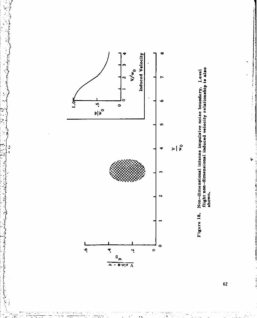
Ftgure 18 presents the maximumImpulsive noise boundaryas a functton of
two non-dtmenstonal veloc1ttes.
The nondtmensionalveloctty variables employedtn thts presentation
are
Vstn_ +, (ordinate) V (abscissa)W0 _
To convert thts nondtmansionalregton to the more familtar rate of
descent agatnst atrspeed presentations, the fltght conditions and rotor
loadtngs mustbe known. The following equations can be used to perfon_:
the conversion:
ili" A-15
1980007615-TSF11

i -),
L_ Vd " Vstny
stny- stn _- w
!l wo -
w - from insert In figure 7 taken from reference 47
iit Although figure 18 identifies the fltght region where the maximumImpulsive
;,._ notse can be expected, the magnitudeof the noise is dependenton the
helicopter configuration. The calculation of the blade/vortex interaction
Impulsive notse wtll be discussednext.
_ Various researchers have investigated the far-field noise resulting..._J
from a blade-vortex interaction. Notable amongthis research is that of
Leverten (ref. 48), Wtdnall (ref. 49) Padakannaya(ref. 50), Fflotas
•" (ref. Sl), and Wright (ref. 25). Leverton's acoustic analysis is based on
Ltghthtll's formulation for far-field soundpressure where the loading on
a small area of the blade can be assumedto act as a point dipole
acoustic source (chord assunmdsmaller than wave-length). Wtdnall
models the interaction as a two-dimensionalatrfotl an an obltque gust.
The analysts was extendedto interaction at the tip region where the
effects of unsteadyaerodynamicsmust be accountedfor. However, in both
techniques, the radiated noise is determinedby the rate-of-change of
the blade force. Padakannaya(ref. 50) uttltzed a moreflextble vortex-
latttce methodfor the calculation on the unsteadyatrloads. Reasonably
A-16
...... ' " '.... " _ '_.... "_ '.... °°'" " " " " 9800076

,4 .p"
I Y:
goodcorrelation between experimental and calculatod data was showntn
this work. Ftlotas (_ef. 51) derives a soundpressure expression by
modeltnga finite aspect rat|o wtng flying at a untfom speedover a carpet
of equally spaced, Infinitely long lines of vortices. Using the method
developedby Nrtght (ref. 8), an equation for the ha_lontc soundpressure
level has been dertved. Thts equation ts dependenton a Fourier repre-
sentation of a stnusotdal blade loadtng occurring once per revolution.
The prediction methodused in this report ts basedon the following
formulationby Wright:
!'!1 _L EPw) me (A-IO)-(F°
)_,_ where E is the numberof interactions occurring every revolution,
!_i:I""__ Pw Is the l°ads°lldlty°rthefractl°n°ftheeffectlvedlskannulusthattheunsteadyloadingregionoccuples,KT is a thrustconstantand)C
i_ Xs is the blade loadtng spectrumfunction.
A research programusing smallrotorsIn a staticoperatingsltua-
tlon (ref. 52) revealed the effect of configuration on the shed vortex
characteristics.It was foundduringthisinvestigationthatan increase
in thenumberof bladesreducedthe axialspacingbetweenvorticesand
increasedthe angularrateat whichtheyrevolveabouttheircentroids
_ of vortictty, which causedthem to becomemore unstable and to diffuse
I sooner.
The effect of collective pitch on vortex strength ts that axial
spacing betweenvortices decreasesalong wtth vortex strength. The ttp
vortices becometncreastggly unstable and diffuse more rapidly. It was
A-Z7
............__--_..:._:......= .. _._...........:;. _ ... •.._,, o"-----_o•.... _-,___.o-.'--__ ,-_-.._o...,,..._.... _;--.:....:::._,_..,L_,_,,-:--_/_,,.::_..,,'":";".
_Y
o i:
_ observed (ref. 5t!) that the effect of tip speedon vortex trajectory was
i ,i _ generally not nottced but that unstable s4nusoldal fluctuations occur
r ,)i; close to the rotor once a strong shockwave forms on the surface of the
atrfot1. Thts Instability was nottced at Machnumbersabove .75 for a
NACA0012 alrfot1.
Installation effects.- Rotor noise due to Installation effects
generally results from the Interaction of the rotor wake interaction
with fuselage, wtng, nacelle, tail fin, or another rotor. The basic
mechanismsthat alter the rotational noise due to distorted tnflow have
been previously discussed in the UnsteadyLoadingTheory sectton. In
the c_seof pushertailrotorconfiguration(rotorthrustvectortoward
fin,inflowoverfin)the turbulentwakesfromthetailfincan give
riseto a severelydistortedinflowwhichsignificantlyincreasesthe
noisegenerated.Thisoccursin a mannersimilarto the rotor-stator
interactionphenomenon(ref.53) whichexistsin turbofanengines.This
unsteadyfinforcehas beenmeasuredon a full-scalehelicopterin jq
reference54. The effectof interactionof themainrotorwakeon the
bladeloadingof a tailrotorwas investigatedin modelstudiesin
reference55. It was notedin thisexperimentthatthemain rotorwake
impingement1ocatlonon the tallrotorproducedincreasedtonenoiseat
tallrotorbladepassagefrequencyand producedtheoccurrenceof combi-
nationtones,i.e.,toneswhicharea functionof boththemainand tall
rotorrotationalfrequency.FigureTg presentsacousticspectrato
i_I 5qO0Hz and showsthe effectof wake locatlonon thetailrotornoise.
' ')" ' :_',-'--,,-----_--C-_-' 7" .'":li_, j ..... '"'o:' _,..... :i,t------,_-_--G---_.....o ......... " d "" " /'": )" "L'-""''-_ _o_" _"--.--.."., :; Ft'Lq':
1980007615-TSF14

:__ APPENDIXBl
BROADBANDNOISE
Initial Investigation into the basic mechanismsof isolated airfoil
noise wasguided by Sharland (ref. 56) and Curle (ref. 57). He suggested
that broadbandnoise from a surface tn a movingflow can be described by
at least three mechanismswhich cause randomfluctuating forces. One
form of randomfluctuating force is the surface pressure field arising
from a turbulent boundarylayer. Another form is the force fluctuations
resulting from shed vorttctty. Finally, if the surface is movingin a
flow which is Initially turbulent, a third componentof fluctuating f_rce
can arise. Oncethe mechants_ of noise generation are postulated in a
phystcal sense, analytical modelscan be derived to indicate howmuch
acoustic power is generated from each source mechanismandwhich parameters
affect the source strength. A detatled discussion of these mechanism
is contained in reference 58 and is summarizednext. The relative impor-
tance of the various broadbandnoise sourcesare then presented in
summaryfigure for a typical helicopter rotor blade. The soundpressures
were calculated along the rotating blade at 10 equal blade areas.
Inflow TurbulenceNoise
This section will uutltne the radiation from a plate in a turbulent
atrflow. If the speed is subsonic, the acoustic wavelength will be
larger than the turbulence scale so that soundfrom plates of dimensions
up to several times the turbulent scale shouldbe calculated simply
B-1
)..
"I _UUU/E)/ :3 /oL_u/

_9
_ from the fluctuating pressures. The expression for the fluctuatingL
it' denst_ from a distribution of fluctuat|ng sources can be wrttten as
!_ [A;.! p. xt " Yt _P|
4,Co3r _, _- dA (6-1)_2
The total acousttc power. W, ts the tntegral of cO-p- over the fteld"_ PO
J) whtch ts
w - 1 I' 3a_tx). dAdA, (B-2)12.___co- J,J,
Z) The retarded source ttme correlation of the rate-of-change of pressure
on the plate must now be evaluated. To obtatn equatton (8°7) tt has
. been assume_ that the plate dimension was of the order of the acoustic
wavelength. If tt is assumedthat this dimension ts small compared to
the wavelength then the "compact" source assumption can be uttllzed and
the retarded ttme assumption dropped. One of the Integrations over
the surface is simply a correlation tntegral which can be written:
,_t Ac (B-31
A'
where Ac ts the correlation area of the pres.'tres. Substituting
equatton (B-3) into equation (B-g) gives:
F: / Ac dAb (B-4)
w 12_plcoT ' _t 2Ab
B-2

• i_
If the blade ts tn a homogeneouspath of turbulence, then the tntegrel
stmply becomesa multtple of the blade area. Ab. To evaluate
equatton (8-4) for the case of |mptngtng turbulence we may take advan-
toge of the results of Kempand Sears (ref. 59) as stmF11fted by
Lowson (ref. 58). Thts shows that the mean ltft per untt span, L, on
an airfoil tn a stnusotdal gust of frequency, _, and magnitude, u, ts
,,pcuu (s-s)
where c. ts the atrfotl chord. To extend thts to three dimensional
conditions we note that the mean ltft tn terns of pressure fluctuations
ts
il L = Pms (tcc)l/2 (B-6)where _c ts the correlation length tn the chordwtse direction.
Let
where ,,, Is a typical frequency, then equation (B-4) becomes
w = 1 A _2A_ 2 ,¢x:U3u2
7 The 2A arises because both sides of the plate radte,te. Put)
_. u 1.-91
where t ts a typtcal lencjth and let Ac . _2. iLc - I_ and A = Ab,
B-3
] 9800076] 5-TSG03
°_'I'
the ftnal result for the sound power radtatod from an atrfotl due to
tnctdent turbulence |s
Zc4
#(12 Ab (B-11)
Equation (B-11) has been plotted tn ftgure 19 as a functton of Hach
number for atyptcal helicopter blade. Brownand 011erhead (ref. 60)
provtde an approximation to the mextmumwake turbulence In terms of the
1| fttng surface parameters:
u_._" U
This result ts stmtlar to that of Sharland (ref. 56) for the same case.
The typtcal frequency for turbulence-induced noise will vary as the
frequency content of the turbulence that Is interacting with the surfaces.
Boundary Layer Noise
The samegeneral formula, equation (B-S), can be applled to radiation'i
from the boundary layer pressure fluctuations acting on the plate. :_;I
Although theory indicates that the direct quadrupole radiation fromJ
the turbulence ts stronger for thts case, tt ts of interest to attempt
a boundary layer pressure fluctuation calculations. Equation (B-n) can
be written as
B-4
..... " ° "'_' "° " _ _ °°"°" °...." " 1980007615-TSG04

• [,2I
Experiments Indicate that p2 ts of the order of 36 x 10-6 q2 where q
ts the dynamichead (_r pQ2). However, there 4s less agreementover the
mgnttudes of the correlation data. Values of correlation areas assumed
by various authors are gtven tn Table I.
TABLE!
PressureCorrelatfon Areas tn a Turbulent BoundaryLayer
Source ,I,c 6" .2Ac _:l • i
Doak 144.006*2 0.63 U/_ 58.000 U2
Ltghtht11 4.406*2 0.05 U/_ 0.011 U2 0
Bull and tttllts 1.786.2
Sharland O.SO0U2
Bull 1.506*2 0.30 U/w 0.135 U2
__ Host recent studtes of boundaryl_yer pressure fluctuat|ons have broadly"-F
agreed wtth Bull's data, (ref. 61). Therefore, the correlation areacan be given by the expression
_1 2A K1U2=' _ C" (B-14)
where the constant K1 ts tn the range 0.1 < K1 < 1.0. Substttu ttng
equatton (B-14) tnto (B-13) ytelds the approximateresult.
B-S
Equatton (B-16) ts shown tn:ftaure 20 tn comparison wtth the otherP
broadband notse source components. The effect of boundary layer notse ts
of second order Importance when co_ared to the other sources. Equatton
(B-15) ts tn agreement wtth Sharland (ref. 56).
Vortex Notse
The vortex notse source can be categorized tnto two components. The
ftrst componentresults from 11ft fluctuations produced at the tretllng ,
edge of the blade by shed vortices, and the second componentoccur.; when
a ttp vortex Interacts wtth a blade ttp. An a]ternate approach to ti_e
determtnat|on of .-ortex notse has been presented by LowsonIn reference 9.
Thts approach ts based on a dimensional dependenceof sound from f]uctuattng
forces.
Presented below are the relationships for vortex shedd;ng notse as
hypothesized by Sharland (Per. 56) and ttp vortex self-Interaction notse
as stated by Lowson (ref. 58).
Vo,rtex shedding.- Beginning wtth equatton (B-4), an expression can
be dertved for the tara1 radtated power due to vortex shedding. Tf we
thtnk of the fluctuating pressure difference as a local 11ft fluctuation¢
....._:_" ":_:'-::-':: _:-_-"_ "_" "_" "" " _....... 1980007615 TSG06

7
_; per untt area, then p can be expressed tn _em of the local l|ft
coefficient C1
_ p. ½ou2cL (e-17)_' klhere U is the local mean velocity parallel to the surface. Therefore,
_i*___ _ . ½_.2_cL (_-1s)
it and
In order to describe the Integral tn equation (B-19_ n terms of the
", flow parameters the mechanismsby whtch lift fluctuations are produced
tn the absence of external excitation must be known. There ts sttll
someuncertainty about the magnitude of lift fluctuations Induced by the
bound circulation changes whtch accompanytratltng edge vortex shedding,
but tt has been suggested that the lift fluctuations can be related to
time fluctuations _,n the boundary layer thickness at the tratltng edge.
On thts basts, for conditions typtcal of propeller blades, the root mean
square of the fluctuating ltft coeff|ctent should be of the numerical
order of the -1/5 power of the Reynolds number. The frequency of the
11ft fluctuattotts should be about the sameas the characteristic fre-
quency of vortex sheddtng at the tratltng edge:
= 2_f = 4__UU (B-20)c
B-7

., i t
where c ts the chord. For Instance, a rotatlng blade wtth a lO-percent
thickness ratto, the correlation area should be governed by the stze of
the larger eddtes at the tratllng edge, whtch m'ight be on the order of
half the sect|on thickness, that ts .05c2. Equatton (5-19) can be
rewritten as
kl = ----_¢ ° I& U4u,'c2 AcdA (B-21)
or tntegrettng,
w - _PuS(RN)"4A120%3 " _ PCo3M6CRN)"4A (5-22)
Atyptcal sound pressure level assumtng a dtpole distribution ts
A
(SP)2 = _- p2Co4 r-_ M6(Rtl)"'4 18-23)
Ttp radiation.- Utilizing the previously derived equatton for
turbulence tnduced notse (eq. B-10)) and assuming that correlation lengths
are on the order of 5 percent of the chord, atyptcal frequency ts
U- 4o_ (5-24)
then substituting Into equation (B-17)
i 3 U6 3 M6ATIO-6 (B-25)W = _ _D__ AT x 10"6-_p Co3'_ C0
l&,
B-8
il"%
','"": _ " ' .....' 1980007615-TSG08

o 'Y
where AT Is the blade tlp area over which the vortex Interaction ts
to occur. This area ts a:;sumedto be approximately 5 percent of the 1
blade area. Zf a dtpole d_stribut|on |s assumed,then the soundpres- !I#q
sure ts
p2%4 M6(sP)2"4- ATx lO.6 (B-26)
Recentwork presented by Clark (ref. 62 ) Indicates that whenblade tip
twist ts used on a helicopter rotor a pronouncedreduction |n noise level
ts evident. Oneeffect of tip twist ts to modify the blade tip vortex.
The four broadbandnoise sources; turbulent (eq. B-11)), a vortex
(eq. (B-23)), tip radiation (eq. (B-26)), and boundarylayer (eq. (5-16))o
; are comparedtn figure 20. This figure showsthe calculated variationt
of these notse sourceswith rotor tip Hachnumberand rotor radius. From
figure 20(a), the predominantnoise source is that resulting from
turbulent inflow. The shedvortex noise source is the secondsource of
importance. The broadbandnoise from the boundarylayer and vortex !_
impingementon the ttp are insignificant.. Figure 20(b) showsthe varta- '_
tton of the various broadbandnoise sources along the rotor radius. The
_ primarybroadbandnoiseradiationportionof the rotorbladeseem to
be theoutboard50 percent.
Dimensionaldepender,ceof soundfromfluctuatlnqforces.-Early
work on broadbandnoiseperfomedby Yudln(ref.63) and latermodified
by Hubbard(ref.lO)and$chlegel(ref.ll)assumedexplicitlythatthe
soundgenerationwas due to trailingedgevortexeffects.Thisworkwas
basedprimarilyon dimensionalarguments.The methoddevelopedin this
B-g )

section has been correlated with measuredbroadbandnoise f,-omhelicopter
rotor blades and is in reasonable agreement. For a point fluctuating
force the basic law governing the soundradiation is well known(Curle,
ref. S7) as
p . _ (B-27)
To calcul.ate the soundradiated by a randompressure field acting over
an area, it is necessary to spltt up the field into correlation areas
Ac over which the pressure maybe regarded as coherent. Thus, the
equivalent point force is given by F = AcP. Becausethe force is
randomthe overall soundpressure is given by the sumof the square of
" the effects of the randomforces. Thus, if there are E individualt
events over the blade the total meansquare soundpressure ts given by
+.i (SP)2 ~ EAc2 (_)2 (B-28)
'} It is usual to assumethat the magnitudeof the fluctuating pressures
;._. acting on the blade is simply proportional to the meanpressure, that
)) is to the meanthrust divided by the blade area Ab,
,, Ac f2 T2|
(SP)2 " k(f) Ab (B-29)iI"
where f is a typical frequency for the fluctuating forces. In turn,
f ma_/be put proportional to a typical velocity divided by a typical
length, _, thus giving
B-IO
. , +
+ +" '...... ='-_ "-+'+........ + ......... "-----" • .7 ++0. +. . " i',0 " • +''.... :" + - " ++ +-+_ + "-,_+___._._ ++....T__+.___........ ++°+ + +° + ,_ ........... + _ + + _:++:., ....¢ + "+ o , +'C ,
: "+'_+ _.....° " .......- ................. " +_"+;+ " ' ++++__++°"+++"_+ + .... +++ +" 5+-TSGI"t."
,.+_ _ ,+ '_ ,+' .' +o ++ o ,+, ,+ .,+. <, + +,, + ,+, _' 'L v .) ,, .. + . .(._ • 7
..... ...... 198000761
n i
V2 T2
_ (SP)2 (_) _ (B30)
The dimensional dependence on V2 T2 Ab"l has been used tn several data
and forms the basts for the recommendedprediction procedure forcollapses,
helicopter rotor broadband noise used tn this report. The spectral features
of the broadband noise are distinctly stmtlar tn all cases. Zt would appear
to define a "universal" sp_.ctral distribution for the broadband noise and to
relate the center frequency to the aircraft's operating parameters. This
has been done Dy Munch (ref. 12).
The sound pressure level of a third octave band of rotor broadband
noise is
VT 3 Ab
SPL1/3 = 20 log (_o) + 10 lo9 _ (cos2 e1 + 1) +$1/3 + f(_L ) + 130 (B 31)
log(cos2el + .1) is the directionality effect as derived by Lowsonwhere 10
(ref 9) The generalized empirical spectrum shape number $I/3, is shown
in figure 20. Data collapses were performed using measured rotor data to
provide this spectrum shape. The peak frequency was determined to be
fp = 240 lo9 T + 2.448 VT + 942 ($I untts)(B 32a)
fp = -240 log T + .746 VT + 786 (Engltsh untts)(B-32b)
The effect of meanrotor 1tit coefficient has been based on the initial
J derivation of equation (B-31) and empirical flight information. Broadband
noise increases rapidly wtth mean lift coefficients greater than approximately
.48. The ltft coefficient function, f((FL), ts defined below as:
B-11
° ...... 5 TSG1"" ...... _4 V ..... " k" '_ " U ' .... " ....... 198000761

.. !
10 log ,_ for _L <- .48
o•8 + 80 log _ fOr EL > .4B
Sound pressure levels for rotors wtth meanlift coefficients muchgreater
than .6 have not been rigorously verified. Practical helicopter fltght
conditions, however, generally have 11ft coefficients less than .6.
B-12
° ., , "o°_, , o"'. .... ' .... .,L._ ,: .:Oo°...° ' ; ,,.o
" " ' ' ...." .... 1980007615/;5C51Z---------------'----
Copyright © 2022 FDOKUMEN