\u003ctitle\u003eSystem for indoor 3D mapping and virtual environments\u003c/title\u003e

An Embedded Vision System for an Unmanned Four-rotor Helicopter
Kirt Lillywhite, Dah-Jye Lee, Beau Tippetts, Spencer Fowers, Aaron Dennis, Brent Nelson, and James Archibald
Robotic Vision Laboratory
Department of Electrical and Computer Engineering Brigham Young University, Provo, UT 84602
ABSTRACT
In this paper an embedded vision system and control module is introduced that is capable of controlling an unmanned four-rotor helicopter and processing live video for various law enforcement, security, military, and civilian applications. The vision system is implemented on a newly designed compact FPGA board (Helios). The Helios board contains a Xilinx Virtex-4 FPGA chip and memory making it capable of implementing real time vision algorithms. A Smooth Automated Intelligent Leveling daughter board (SAIL), attached to the Helios board, collects attitude and heading information to be processed in order to control the unmanned helicopter. The SAIL board uses an electrolytic tilt sensor, compass, voltage level converters, and analog to digital converters to perform its operations. While level flight can be maintained, problems stemming from the characteristics of the tilt sensor limits maneuverability of the helicopter. The embedded vision system has proven to give very good results in its performance of a number of real-time robotic vision algorithms.
Keywords: field programmable gate arrays (FPGA), robot vision, unmanned helicopter, attitude control
1. INTRODUCTION
Interest in hovering unmanned aerial vehicles (hUAV) has increased in recent years. Hovering is made possible because these vehicles allow for more degrees of freedom in movement as compared to traditional fixed wing UAVs. Hovering allows the vehicle to remain in place when needed, fly closer to objects of concern, and maneuver in ways that other UAVs cannot. Hovering unmanned vehicles have been proposed for uses in crop dusting, remote sensing [1], cinematography, aerial mapping [2], tracking [3], inspection, law enforcement, surveillance [4], search and rescue, etc.
Interest is also developing in micro-UAVs. These aircraft are much less costly than their counterparts and are able to move about in environments that larger aircraft cannot, such as indoors environments. Micro-UAVs have several disadvantages however. In outdoor applications micro-UAVs have significant problems in windy or stormy conditions. Also micro-UAVs have very small payload capabilities making it difficult to carry sufficient equipment to complete many tasks.
Many current micro-UAV implementations use tele-operation [5], in which one or more people control each UAV. If the UAV were to be provided with some semblance of autonomy, then much of the burden of controlling the UAV could be removed from the operator, and the operator would be free to help in other tasks. For example, in a search and rescue application using tele-operation of the UAV, the user would have to manually control every movement of the UAV from a remote location. His attention would be spent trying to keep the UAVs from colliding with obstacles as well as making sure that the purpose of the flight is being fulfilled. This would provide very little benefit over a full-size manned aircraft. If the UAVs had enough autonomy to recognize where it had already been as well as being able to recognize obstacles and avoid them, then one user would be able to control multiple UAVs at once. One person could then cover much more ground with a fleet of UAVs more efficiently than other alternatives.
Please verify that (1) all pages are present, (2) all figures are acceptable, (3) all fonts and special characters are correct, and (4) all text and figures fit within themargin lines shown on this review document. Return to your MySPIE ToDo list and approve or disapprove this submission.
6384-24 V. 2 (p.1 of 9) / Color: No / Format: Letter / Date: 7/15/2006 3:20:01 PM
SPIE USE: ____ DB Check, ____ Prod Check, Notes:

Current autonomous micro-UAVs require a computer on the ground to process video because equipment to do so cannot be carried on the UAV itself [6]. This limits the range of the aircraft and hinders its ability to perform certain tasks because of the time required to transmit images and commands back and forth from the ground station.
A useful micro-UAV with an onboard vision system needs to be rugged enough to handle a military environment, run in real-time, be compact, require a minimum amount of power, and be standardized and flexible enough to work on a variety of existing and future platforms. The system must be able to follow general guidance, as opposed to needing detailed commands, from the operator. The system must be able to detect and avoid obvious obstacles. The system must also have minimal electro-magnetic signature so as to be less likely to be detected and less likely to interfere with other systems.
In this paper we will look at the autonomous micro-hUAV being developed at the Robotic Vision Lab (RVL) at Brigham Young University (BYU). Specifically we will discuss the four-rotor micro-helicopter platform that we are using in section two with some discussion of traditional helicopters, the embedded vision system design in section three, the results and challenges of our work in section four, and future work in section five. Our research focus is not in developing the underlying helicopter technology or control, so much as it is in developing a vision system to be used primarily on a hUAV and on other space or weight restrained applications.
2. FOUR-ROTOR HELICOPTER PLATFORM
We will now discuss the four-rotor helicopter that we are currently using. A four-rotor helicopter has several advantages over traditional helicopters that made it an attractive platform for us to use. A four-rotor helicopter design has more simplistic hardware and is easier to control while retaining the maneuverability found in traditional helicopters. The four rotor design eliminates the need for complicated hardware, such as swash plates, for directional control. This translates to 95% fewer parts than conventional RC helicopters. Furthermore the four rotor design is more stable because the moments of inertia are placed around the outside of the payload. This in effect takes the gyroscopic effect seen in traditional helicopters, which helps keep the helicopter level, and multiplies it by four. This also allows for a lower center of balance and the easy addition of a centralized payload. A four-rotor design has six degrees of freedom; pitch, roll, yaw, and three location dimensions.
Figure 1: DraganFlyer V Ti
Please verify that (1) all pages are present, (2) all figures are acceptable, (3) all fonts and special characters are correct, and (4) all text and figures fit within themargin lines shown on this review document. Return to your MySPIE ToDo list and approve or disapprove this submission.
6384-24 V. 2 (p.2 of 9) / Color: No / Format: Letter / Date: 7/15/2006 3:20:01 PM
SPIE USE: ____ DB Check, ____ Prod Check, Notes:

Tests were done with a DraganFlyer V Ti (shown in Figure 1), a commercially available four-rotor helicopter. The DraganFlyer flies on a 3-Cell, 1320mAh, 11.1 V Lithium Polymer battery which supports flight times between 13 and 17 minutes. This model can lift 4 ounces in addition to its own 16 ounces of weight effortlessly using four dual-blade rotors mounted to brushed DC motors. It can sustain velocities of up to 30 mph.
Without any help the DraganFlyer platform is impossible for a human to fly by remote control because of the instability of the system. To help a human maintain level flight the DraganFlyer comes outfitted with rate gyroscopes on three axes and low-cost thermopiles. The rate gyroscopes limit the rate at which the aircraft can change its pitch, roll, or yaw. The rate gyroscopes in essence smooth out the movement of the aircraft and cause the aircraft to be much more stable. The thermopiles are placed in four directions around the center of the aircraft. The four thermopiles and a microprocessor constitute the thermal intelligence of the aircraft. The thermal intelligence works by reading the temperature in four directions around the DraganFlyer. If all four sensors have equal readings, then the DraganFlyer assumes it is level. Otherwise the DraganFlyer will use the temperature difference between sky and ground to determine its orientation. The thermal intelligence does an excellent job of making the platform stable enough for human controlled flight outdoors with radio control; however, they can only be used outside with no buildings close by because the heat signatures of the buildings distort the DraganFlyer’s level flight computations
One advantage of our micro-hUAV is its ability to fly indoors. It uses electric motors to avoid harmful emissions and is small enough that indoor flight is possible. In order to accommodate controllable, stable indoor flight the thermal sensors were replaced by the Smooth Automated Intelligent Leveling (SAIL) board developed by the RVL at BYU. It achieves level flight by using a Fredericks TrueTilt, Dual Axis, Wide Angle, Electrolytic Tilt Sensor 0717 (shown in Figure 2) and the rate gyroscopes that are already attached to the DraganFlyer. Gravity pulls the electrolytic solution in the tilt sensor parallel with the earth’s surface. By analyzing the voltage levels on the pins in the bubble, the pitch and roll of the helicopter can be determined. The electrolytic bubble is simple and can perform readings many times a second. Furthermore, it is invariant to outside conditions and will perform well in both outdoor and indoor situations. The rate gyroscopes greatly simplify the control problem and change the problem from a 3rd order control problem to a linear control problem. The electrolytic bubble works alongside a Dinsmore R1655 compass (shown in Figure 2). While readings from the electrolytic sensor are used to maintain level flight the compass readings are used to control yaw. Level converters are used on the SAIL board to convert between the 5 volt levels used on the DraganFlyer and the 3.5 volt signals used by the embedded vision system for serial communication. A four channel eight bit analog to digital converter is used to convert analog signals from the compass and electrolytic sensor to digital signals for use in the vision system.
Figure 2: (a) Fredericks electrolytic tilt and Dinsmore compass (b) SAIL board
Please verify that (1) all pages are present, (2) all figures are acceptable, (3) all fonts and special characters are correct, and (4) all text and figures fit within themargin lines shown on this review document. Return to your MySPIE ToDo list and approve or disapprove this submission.
6384-24 V. 2 (p.3 of 9) / Color: No / Format: Letter / Date: 7/15/2006 3:20:01 PM
SPIE USE: ____ DB Check, ____ Prod Check, Notes:

Spectrolutions, Inc., designer of the DraganFlyer board, was kind enough to modify the DraganFlyer to except serial commands, overriding the commands coming from the remote control. The unmodified DraganFlyer receives radio frequency (RF) signals and sends what it receives out a serial port and then continues flight using the command obtained through the RF signal. The modified DraganFlyer continues to receive RF signals and sends them out over the serial port but when the custom serial override switch is enabled the flyer takes input received on the serial port as the command to control the aircraft. This allows us to continue to use the remote control during testing to control some aspects of the aircraft manually but also be able to control the DraganFlyer with our Helios board. Figure 3 outlines communication flow.
3. EMBEDDED VISION SYSTEM
This section describes the embedded vision system focusing on the design features that give us a low-power, light weight system capable of real-time vision processing. Figure 4 is a block diagram of the embedded vision system. This system is designed to function as a black box and so it is imperative that a standard interface be devised such that the
Figure 3: Communication flow
Figure 4: Block diagram of embedded vision system
Please verify that (1) all pages are present, (2) all figures are acceptable, (3) all fonts and special characters are correct, and (4) all text and figures fit within themargin lines shown on this review document. Return to your MySPIE ToDo list and approve or disapprove this submission.
6384-24 V. 2 (p.4 of 9) / Color: No / Format: Letter / Date: 7/15/2006 3:20:01 PM
SPIE USE: ____ DB Check, ____ Prod Check, Notes:
system can control the vehicle and receive information as needed. Optional sensors may be desired, such as GPS if such signals are available, and so the system is designed to allow multiple configurations. Also it should be able to be used on any numbers of vehicles where space and power are a premium. For our purposes a hovering platform is being used but the embedded vision system has also been used on small ground vehicles and could just as easily be used on fixed wing UAVs or other craft.
At the heart of embedded vision system is a Field Programmable Gate Array (FPGA). Recently, FPGAs have been used in answer to the growing demands of creating real-time processing. FPGAs have massive parallelism capabilities and thus many algorithms done on FPGAs can significantly outperform modern general purpose processors like the Pentium 4 [7]. FPGAs can be used in a huge range of applications such as DSP [8], Application Specific Integrated Circuit (ASIC) prototyping [9], cryptography [10], speech recognition [11], etc.
FPGAs also allow a user to try multiple different configurations and design ideas in a shorter period of time than their corresponding ASICs since the only cost in redesigning the part is the synthesis that has to be redone when changes are made. This decrease in turn-around time and cost outweighs, at least for preproduction units, the cost of processing speed that ASICs are able to achieve over their FPGA counterparts. In addition, multiple previously designed components can be integrated onto a single FPGA chip where intermediary boards were needed to allow these same components to work together on an ASIC. FPGAs have also been designed with built in processor units, and our embedded vision system makes full use of this capability, using the processor to run a Real-Time Operating System (RTOS) to allow finer control over the UAV. These processor units are generally set up in such a way that custom components can be integrated with them. Ultimately, it is the FPGA that allows control of the UAV. We use a microC/OS, a priority based pre-emptive multitasking operating system. It is very well tested, robust, and well suited for time critical systems.
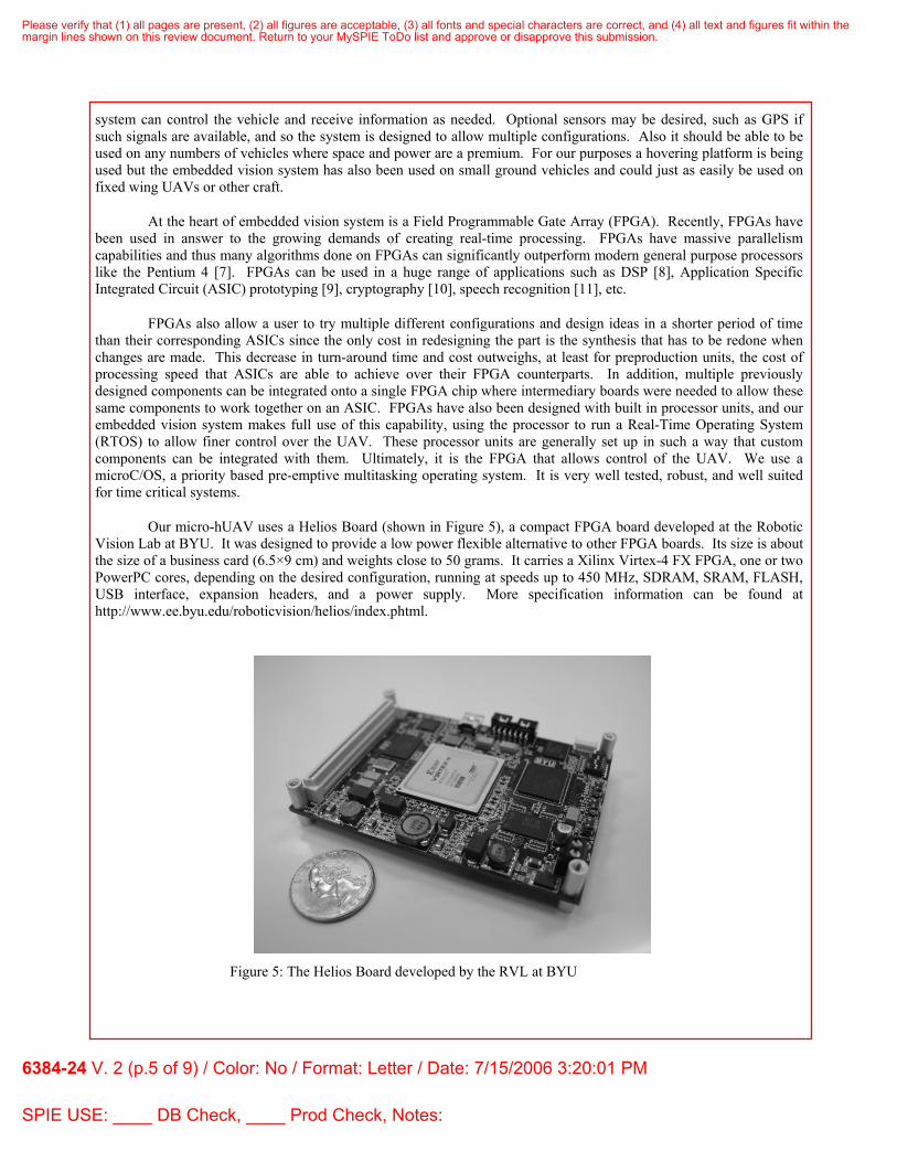
Our micro-hUAV uses a Helios Board (shown in Figure 5), a compact FPGA board developed at the Robotic Vision Lab at BYU. It was designed to provide a low power flexible alternative to other FPGA boards. Its size is about the size of a business card (6.5×9 cm) and weights close to 50 grams. It carries a Xilinx Virtex-4 FX FPGA, one or two PowerPC cores, depending on the desired configuration, running at speeds up to 450 MHz, SDRAM, SRAM, FLASH, USB interface, expansion headers, and a power supply. More specification information can be found at http://www.ee.byu.edu/roboticvision/helios/index.phtml.
Figure 5: The Helios Board developed by the RVL at BYU
Please verify that (1) all pages are present, (2) all figures are acceptable, (3) all fonts and special characters are correct, and (4) all text and figures fit within themargin lines shown on this review document. Return to your MySPIE ToDo list and approve or disapprove this submission.
6384-24 V. 2 (p.5 of 9) / Color: No / Format: Letter / Date: 7/15/2006 3:20:01 PM
SPIE USE: ____ DB Check, ____ Prod Check, Notes:

Due to the advances in consumer digital cameras and cell phone image capturing features, a programmable and low power miniature CMOS imager was available for this project. In our previous work, we had designed and built a miniature image sensing device (shown in figure 6) for development and testing. Mounted on the sensor board is a small Micron MT9V111 image sensor. It uses FFC (flat flexible cable) and FPC (flat printed cable) connectors and cables, allowing for a very small, 4 cm, package. This sensor board including PCB, micro lens, and the FPC cable weighs less than 3 grams total. Because of its miniature size, this sensor board can be easily mounted on the fixed frame or gimbals for pan and tilt. The MT9V111 is capable of high resolution, 1280×1024, color images.
As the image is captured by the camera it is sent both to the vision processing unit on the Helios board and to the ground base if needed. The camera captures images digitally at 30 frames a second. Analog signals can be sent over greater distances compared to digital signals and so a digital to analog converter (DAC) is used to convert the video to NTSC format and that signal is transmitted to the ground station. For some applications and testing it is convenient to be able to see what the UAV sees. This process is not necessary though because the images can be processed onboard by the Helios. Any number of vision algorithms can be used in the vision processing unit. The Helios board simply needs to be reprogrammed with a new vision algorithm. With an ASIC, while it can run at greater speeds than an FPGA, it can only perform the operation for which it was built. The Helios FPGA gives our system the flexibility that we need.
The Helios board takes in the images from the camera, stores them in memory, processes the images as specified by the vision algorithm, takes in readings from the SAIL board, and controls the flight of the aircraft with this information. In some applications additional high level commands can be sent to the Helios from the ground station.
4. RESULTS
A working prototype of the entire flying platform and embedded vision system does not yet exist but all of the pieces that make up the platform have been tested. This first iteration of the platform was never meant to be a working prototype but a platform on which tests could be made. The DraganFlyer has a few shortcomings which makes it unsuitable for anything but testing. It is being used as a test bench before we invest in building our own aircraft and while further research is being done. Its most severe shortcoming is that it can only lift four ounces in addition to its own weight making it incapable of lifting all of the electronics and sensors that we want to place on it. This is compounded by the altitude of our area (4,549 ft.). The higher elevation makes it harder for the DraganFlyer to lift
Figure 6: CMOS imager used in vision system
Please verify that (1) all pages are present, (2) all figures are acceptable, (3) all fonts and special characters are correct, and (4) all text and figures fit within themargin lines shown on this review document. Return to your MySPIE ToDo list and approve or disapprove this submission.
6384-24 V. 2 (p.6 of 9) / Color: No / Format: Letter / Date: 7/15/2006 3:20:01 PM
SPIE USE: ____ DB Check, ____ Prod Check, Notes:

because the air is much thinner than at sea level. It is able to carry most of the electronics needed but is unable to lift all of the components to test the entire system together. The brushed motors heat up quickly, especially when weighted down, and the motors become less reliable. The DraganFlyer is unable to sustain extensive flight times with such a large payload compounded with the previously described issues. This is also unacceptable for many applications. Our goal is to get at least 30 to 45 minutes of flight time if possible. The DraganFlyer’s propellers are also a problem. They are exposed becoming a safety hazard to humans and other objects in the vicinity of it. The propellers themselves also break fairly easily and must be replaced frequently after crashing during testing.
The Helios board has been tested extensively. Individual tests were done to test the camera interface, the DDR memory, the communication to the modem, servos, encoders, compass, communication with the DAC, and video transmission. It was also used in a senior project at BYU in which students implemented a simple color segmentation algorithm completely in hardware on small RC trucks. The trucks were able to run various courses going faster than was originally expected. Images were converted from RGB to HSI color space, segmented for red, green, and orange, and processed to produce a command all in real-time.
The SAIL board tracks attitude and yaw but has no sensors that measure the translational motion of the DraganFlyer. Movements on the plane of the aircraft as well as movements perpendicular to the plane of the aircraft are undetectable. This causes the aircraft to drift without being able to compensate. In the design, drift was to be accounted for using the camera, but because the whole system could not be assembled at once and be under the weight restrictions, drift was unavoidable. Using feature tracking on the images captured by the camera, translational movements on the plane of the aircraft, as well as perpendicular to the plane of the aircraft, can be measured and then corrected for. This research has already begun at BYU and has obtained excellent results.
To test the SAIL board, the SAIL board and Helios board were attached to the DraganFlyer and commands were given to hover above the ground. The overall thrust of the motors were controlled with the RC controller that came with the DraganFlyer while the Helios and SAIL board attempted to kept level flight. Tests seemed to show that level flight was maintained even after colliding with obstacles. The aircraft never tipped far to one side or the other but due to the difficulty in controlling drift it was hard to determine what degree of level flight was maintained. After running for a short period of time the motors heated up and would cut out for very short periods of time creating sporadic dips in movement which shortened test time and did not allow us to test in large areas and observe the full effect of drift. The weight of the payload, the elevation, and the fact that brushed motors heat up due to internal friction caused glitches that made it again difficult to measure what level of flight the aircraft maintained. As mentioned in section 2 the DraganFlyer came equipped with rate gyroscopes. In the end design all of the DraganFlyer sensors were to be removed. In the test done with the SAIL board these sensors were not removed. It is certain that these helped in the control of the aircraft but it is hard to determine how much the rate gyroscopes attributed to the level flight of the aircraft.
In these tests several problems were found with the SAIL board. These problems stem from the deficiencies with the electrolytic tilt sensor. The tilt sensor can be read at 400 Hz but those readings are only updated every 10 Hz. It is suspected that the latency of the tilt sensor hurt the performance of the SAIL board as helicopters can exhibit 40-60 degrees per second angular velocity under normal operating conditions [12]. It was also discovered that the tilt sensor’s electrolytic fluid solution was magnetic and interfered with the compass operation. This however could be overcome by either purchasing a non-magnetic tilt sensor or placing the components far enough apart that they could not interfere with each other. A non-magnetic tilt sensor however has longer latencies (can be as long as one full second) than magnetic tilt sensors and would have created other problems. Perhaps the most damaging problem with the tilt sensor is that all accuracy is lost while executing a banking turn. The tilt sensor uses the force of gravity to determine level flight. During flight however, forces felt due to acceleration in effect changed the direction of the gravitational pull on the electrolytic fluid in the tilt sensor. This could in theory be partially overcome by correcting the values from the tilt sensor with accelerometers or some other sensors but this would require basically building an inertial measurement unit. Our research focus is on robot vision and because these units are commercially available in many forms it is not our interest to pursue building one any further.
Please verify that (1) all pages are present, (2) all figures are acceptable, (3) all fonts and special characters are correct, and (4) all text and figures fit within themargin lines shown on this review document. Return to your MySPIE ToDo list and approve or disapprove this submission.
6384-24 V. 2 (p.7 of 9) / Color: No / Format: Letter / Date: 7/15/2006 3:20:01 PM
SPIE USE: ____ DB Check, ____ Prod Check, Notes:
5. FUTURE WORK While tests were being performed with the DraganFlyer, we were designing a new helicopter capable of lifting the electronics that we need. This new helicopter is not finished yet but current results are promising. Stronger motors have been added that can lift an estimated four pounds. Brushless motors are used which are more efficient and create less heat than brushed motors. More battery packs have been added to give us at least 30 minutes of flight time. Shrouds were added which surround the blades adding to the effective length of the propellers and protect the propellers from being broken.
In future work the SAIL board will be removed completely. It was hoped to be a simple solution to our problem but we realized that a more sophisticated solution was needed. An autopilot board developed at BYU will be used. This board is sold commercially through Procerus Technologies. It is advertised as the world’s smallest and lightest autopilot. It weighs 16.65 grams and measures 2” x 1.37” x .47”. It uses three rate gyroscopes and three accelerometers to estimate attitude. It is much more robust under increased g-forces in flight and will provide more functionality than the SAIL board was capable of. It allows for a GPS signal, will compensate for temperature changes, measure airspeed, measure altitude, estimate wind conditions, provide compass readings, and do some of the computation onboard that would otherwise have to be done on the Helios board. Its light weight and flexibility make it clearly a better alternative to the SAIL board.
6. CONCLUSION
We proposed an embedded vision system on a four-rotor helicopter. The embedded vision system gives our micro-hUAV a definite advantage in many applications over other UAVs. The embedded vision system has proven to be very effective but we are missing the hovering platform on which to implement the vision system. Our interest lies primarily in the embedded vision system, but out of necessity we are required to building a hovering platform. The first iteration of our platform consisting of the DraganFlyer, SAIL board and Helios board gave us many necessary insights in order to successfully complete our project. Our future work will build off of these insights and allow us to implement the entire embedded vision system onboard a custom-built quad-rotor platform.
REFERENCES
1. Archer, F.; Shutko, A.M.; Coleman, T.L., Haldin, A.; Novichikhin E., Sidorov, I., “Introduction, Overview, and Status of the Microwave Autonomous Copter System (MACS),” Geoscience and Remote Sensing Symposium, Proceedings 2004 IEEE International Conference of, pp.3574-3576, 2004.
2. Sugiura, R.; Fukagawa, T.; Noguchi, N.; Ishii, K.; Shibata, Y.; Toriyama, K., "Field information system using an agricultural helicopter towards precision farming," Advanced Intelligent Mechatronics, 2003. AIM 2003. Proceedings. 2003 IEEE/ASME International Conference on , vol.2, no.pp. 1073- 1078 vol.2, 20-24 July 2003
3. Rock, S.M.; Frew, E.W.; Jones, H.; LeMaster, E.A.; Woodley, B.R., "Combined CDGPS and vision-based control of a small autonomous helicopter," American Control Conference, 1998. Proceedings of the 1998 , vol.2, no.pp.694-698 vol.2, 21-26 Jun 1998
4. Luo Jun, Xie Shaorong, Gong Zhenbang, Rao Jinjun, “Subminiature Unmanned Surveillance Aircraft and its Ground Control Station for Security”, Proceedings of 2005 IEEE International Workshop on Safety, Security and Rescue Robotic, pp.116-119, Kobe, June 2005.
5. Koeda, M.; Matsumoto, Y.; Ogasawara, T., "Development of an Immersive Teleoperating System for Unmanned Helicopter," Robot and Human Interactive Communication, 2002. Proceedings. 11th IEEE International Workshop on , vol., no.pp. 47- 52, 2002.
6. Roberts, J.M.; Corke, P.I.; Buskey, G., "Low-cost flight control system for a small autonomous helicopter," Robotics and Automation, 2003. Proceedings. ICRA '03. IEEE International Conference on , vol.1, no.pp.546- 551 vol.1, 14-19 Sept. 2003
Please verify that (1) all pages are present, (2) all figures are acceptable, (3) all fonts and special characters are correct, and (4) all text and figures fit within themargin lines shown on this review document. Return to your MySPIE ToDo list and approve or disapprove this submission.
6384-24 V. 2 (p.8 of 9) / Color: No / Format: Letter / Date: 7/15/2006 3:20:01 PM
SPIE USE: ____ DB Check, ____ Prod Check, Notes:

7. Pasciak, A.S.; Ford, J.R., "A New High Speed Solution for the Evaluation of Monte Carlo Radiation Transport Computations," Nuclear Science, IEEE Transactions on , vol.53, no.2pp. 491- 499, April 2006
8. Hutchings B., Nelson B. “GigaOp DSP On FPGA,” Journal of VLSI Signal Processing Systems, vol. 36 no.1, pp.41-55, 2004.
9. R. Tessier, J. Babb, M. DahI, S. Hanono, and A. Agarwal, "The Virtual Wires Emulation System: A gate-efficient ASIC prototyping environment," ACM International Workshop on Field-Programmable Gate Arrays, 1994, ACM. no.pp.2-11, February 1994.
10. Adam J. Elbirt, W. Yip, B. Chetwynd, Christof Paar. “An FPGA Implementation and Performance Evaluation of the AES Block Cipher Candidate Algorithm Finalists,” AES Candidate Conference, pp.13-27, 2000.
11. Nedevschi, S., Patra, R. K., Brewer, E. A. “Hardware speech recognition for user interfaces in low cost, low power devices,” Proceedings of the 42nd Annual Conference on Design Automation, pp.684-689, ACM Press, New York, 2005).
12. Omead Amidi, “An Autonomous Vision-Guided Helicopter” (PhD dissertation, Carnegie Mellon University, 1996), pp2.
Please verify that (1) all pages are present, (2) all figures are acceptable, (3) all fonts and special characters are correct, and (4) all text and figures fit within themargin lines shown on this review document. Return to your MySPIE ToDo list and approve or disapprove this submission.
6384-24 V. 2 (p.9 of 9) / Color: No / Format: Letter / Date: 7/15/2006 3:20:01 PM
SPIE USE: ____ DB Check, ____ Prod Check, Notes:
Copyright © 2022 FDOKUMEN