UMD - CONDOR - Mountain Rescue Helicopter
127
UMD - CONDOR Mountain Rescue Helicopter Alfred Gessow Rotorcraft Center Department of Aerospace Engineering University of Maryland College Park, MD 20742 June 1, 2004
-
Upload
khangminh22 -
Category
Documents
-
view
0 -
download
0
Transcript of UMD - CONDOR - Mountain Rescue Helicopter

UMD - CONDOR
Mountain Rescue Helicopter
Alfred Gessow Rotorcraft Center
Department of Aerospace Engineering University of Maryland
College Park, MD 20742 June 1, 2004

University of Maryland
Alfred Gessow Rotorcraft Center
Department of Aerospace Engineering
University of Maryland
College Park, MD 20742
UMD - Condor Design Proposal
In response to the 2004 Annual AHS International
Student Design Competition - Graduate Category
June 1, 2004
_______________________________
Joshua Ellison
_______________________________
Joseph Conroy
_______________________________
Jaye Falls
_______________________________
Shaju John
_______________________________
Dr. Inderjit Chopra - Faculty Advisor
_______________________________
Robin Preator
_______________________________
Abhishek Abhishek

UMD - Condor Acknowledgements
The Condor design team would like to acknowledge the following people and thank them for
their valuable assistance and guidance.
Dr. Vengalattore T. Nagaraj - Research Scientist, Dept. of Aerospace Engineering, University of
Maryland, College Park.
Dr. Marat Tishchenko - Former Chief Designer, Mil Design Bureau.
Dr. Inderjit Chopra - Professor, Dept. of Aerospace Engineering, University of Maryland, College
Park.
Dr. J. Gordon Leishman - Professor, Dept. of Aerospace Engineering, University of Maryland,
College Park.
Dr. Jayant Sirohi - Research Associate, Dept. of Aerospace Engineering, University of Maryland,
College Park.
Dr. David Lewicki - Research Scientist, NASA Glenn, Cleveland, Ohio.
Paul Samuel, Shreyas Ananthan, Jinsong Bao, Anubhav Datta, Beatrice Roget, Gaurav Gopalan,
Beerinder Singh, Jayasimha Atulasimha, Maria Ribera, Vineet Gupta, Wei Hu - Graduate
Students, Department of Aerospace Engineering, University of Maryland, College Park.
Mark Rager - Director of Maintenance, Glenwood Aviation LLC. Jeff McDaniels, Lifeport, Inc.
i

UMD - Condor Table of Contents
ACKNOWLEDGEMENTS.......................................................................................................................... I LIST OF FIGURES ................................................................................................................................... VI LIST OF TABLES .................................................................................................................................. VIII LIST OF SYMBOLS / ABBREVIATIONS ............................................................................................. IX RFP COMPLIANCE ...................................................................................................................................X EXECUTIVE SUMMARY........................................................................................................................ XI PERFORMANCE SUMMARY AND DESIGN FEATURES ...................................................................1 SECTION 1 - INTRODUCTION.................................................................................................................4 SECTION 2 - IDENTIFICATION OF DESIGN DRIVERS.....................................................................4
2.1 - MOUNTAIN SAR PERFORMANCE CAPABILITIES ..................................................................................5 2.1.1 - SAR Mission Requirements.........................................................................................................5 2.1.2 - Mission Profile ...........................................................................................................................5
2.2 - OPERATING ENVIRONMENT.................................................................................................................6 2.3 - RFP REQUIREMENTS ...........................................................................................................................7 2.4 - DESIGN DRIVERS.................................................................................................................................7
SECTION 3 - CONFIGURATION SELECTION......................................................................................9 3.1 - QUALITATIVE EVALUATION ................................................................................................................9
3.1.1 - Evaluation Method .....................................................................................................................9 3.1.2 - Evaluation Results ....................................................................................................................10
3.2 - HISTORICAL SURVEY.........................................................................................................................12 3.3 - FINAL CONFIGURATION SELECTION ..................................................................................................12
SECTION 4 - PRELIMINARY SIZING...................................................................................................13 4.1 - DESIGN REQUIREMENTS ....................................................................................................................13 4.2 - METHOD OF ANALYSIS......................................................................................................................14 4.3 - TRADE STUDIES.................................................................................................................................15 4.4 - INITIAL SIZING ..................................................................................................................................15 4.5 - ENGINE SELECTION ...........................................................................................................................19 4.6 - SELECTION OF FINAL CONFIGURATION .............................................................................................21
SECTION 5 - AIRCRAFT CERTIFICATION ........................................................................................25 5.1 - APPLICABILITY..................................................................................................................................26 5.2 - CATEGORY A VS. CATEGORY B ........................................................................................................26 5.3 - SUMMARY OF DESIGN REQUIREMENTS FROM CFR...........................................................................27
SECTION 6 - MAIN ROTOR & HUB DESIGN......................................................................................28 6.1 - BASELINE ROTOR DESIGN .................................................................................................................28
6.1.1 Blade Twist .................................................................................................................................28 6.1.2 Airfoil Sections............................................................................................................................29 6.1.3 Tip Speed ....................................................................................................................................29 6.1.4 Tip Geometry ..............................................................................................................................29
6.2 - SWASHPLATELESS ROTOR CONTROL.................................................................................................30 6.2.1 - Trailing Edge Flaps..................................................................................................................30 6.2.2 - Lift Flaps vs. Moment Flaps .....................................................................................................31 6.2.3 - Details of Moment Flap Design................................................................................................32 6.2.4 - Moment Flap: Parametric Design Studies ...............................................................................34
6.3 - COMPACT FLAP ACTUATOR...............................................................................................................36
ii

UMD - Condor
6.3.1 - Actuator Design........................................................................................................................36 6.3.2 - Actuator Mounting and Operation ...........................................................................................38 6.3.3 - Safety and Monitoring ..............................................................................................................39
6.4 - SLIP RING ..........................................................................................................................................39 6.5 - BLADE STRUCTURAL DESIGN............................................................................................................39
6.5.1 - Blade Design Details ................................................................................................................39 6.5.2 - Lightning Protection and Electromagnetic Shielding...............................................................42
6.6 - HUB DESIGN......................................................................................................................................42 6.7 - AUTOROTATION CHARACTERISTICS ..................................................................................................43 6.8 - ACTIVE VIBRATION CONTROL...........................................................................................................44 6.9 - ROTOR DYNAMICS ............................................................................................................................45
6.9.1 - Dynamic Analysis .....................................................................................................................45 6.9.2 - Aeroelastic Analysis .................................................................................................................46 6.9.3 - Ground & Air Resonance .........................................................................................................47
SECTION 7 - FAN-IN-FIN ANTI-TORQUE SYSTEM..........................................................................48 7.1 - ANTI-TORQUE SYSTEM TRADE STUDY..............................................................................................48 7.2 - FAN-IN-FIN DETAILED DESIGN..........................................................................................................49
7.2.1 - Duct/Shroud Design .................................................................................................................50 7.2.2 - Fan Design ...............................................................................................................................51 7.2.3 - Vertical Fin Design ..................................................................................................................53
SECTION 8 - AIRFRAME/LANDING GEAR DESIGN ........................................................................54 8.1 - AIRFRAME DESIGN ............................................................................................................................54
8.1.1 - Structural Details .....................................................................................................................54 8.1.2 - Crash Resistance ......................................................................................................................56 8.1.3 - Materials, Manufacturing, Construction ..................................................................................56 8.1.4 - Doors ........................................................................................................................................57
8.2 - LANDING GEAR DESIGN ....................................................................................................................57 8.2.1 - Configuration ...........................................................................................................................58 8.2.2 - Tire Sizing.................................................................................................................................59 8.2.3 - Oleo Sizing ...............................................................................................................................59
SECTION 9 - DETAILS OF COCKPIT/CABIN SYSTEMS..................................................................59 9.1 - CREW STATION FEATURES ................................................................................................................59 9.2 - COCKPIT LAYOUT..............................................................................................................................60
9.2.1 - Cockpit and Cabin Access ........................................................................................................60 9.2.2 - Pilot/Copilot Stations ...............................................................................................................60
9.3 - COCKPIT SYSTEMS ............................................................................................................................62 9.3.1 - Sensor Suite ..............................................................................................................................62 9.3.2 - Multi-function Displays ............................................................................................................62 9.3.3 - Communication Systems ...........................................................................................................63 9.3.4 - Mission Systems Equipment......................................................................................................63 9.3.5 - Flight Management System ......................................................................................................64 9.3.6 - Alternate Avionics Package......................................................................................................65
9.4 - CABIN SYSTEMS ................................................................................................................................65 9.5 - CABIN EQUIPMENT LAYOUT..............................................................................................................65
SECTION 10 - MISSION EQUIPMENT..................................................................................................67 10.1 - RESCUE GEAR .................................................................................................................................67
10.1.1 - Retrieval Gear ........................................................................................................................67 10.1.2 - Hoist .......................................................................................................................................68 10.1.3 - Additional Rescue Equipment.................................................................................................68
10.2 - MEDICAL EQUIPMENT .....................................................................................................................68 SECTION 11 - FLIGHT CONTROL SYSTEM.......................................................................................70
iii
UMD - Condor
11.1 - DESIGN OF FCS ...............................................................................................................................70 11.1.1 - Details of Flight Control System ............................................................................................70 11.1.2 - Neural Network Based Fault Detection..................................................................................72
11.2 - STABILITY AND CONTROL ANALYSIS ..............................................................................................73 11.2.1 - Lateral & Longitudinal Modes ...............................................................................................73 11.2.2 - Tail Sizing...............................................................................................................................74
11.3 - HANDLING QUALITIES.....................................................................................................................74 SECTION 12 - MECHANICAL SUBSYSTEMS (ENGINE/TRANSMISSION) ..................................76
12.1 - ENGINES ..........................................................................................................................................76 12.1.1 - Engine Structural Integration.................................................................................................76 12.1.2 - Engine Performance...............................................................................................................77 12.1.3 - Engine Subsystems..................................................................................................................77
12.2 - TRANSMISSION DESIGN ...................................................................................................................77 12.2.1 - Design Baselines ....................................................................................................................77 12.2.2 - Configuration Study................................................................................................................78 12.2.3 - Optimization Considerations ..................................................................................................80 12.2.4 - Structural Integration .............................................................................................................82 12.2.5 - Stress Calculations .................................................................................................................82 12.2.6 - Weight Estimation ..................................................................................................................83 12.2.7 - Generator and APU................................................................................................................83 12.2.8 - Tail Rotor Drive and Gearbox................................................................................................84 12.2.9 - Power Losses ..........................................................................................................................84 12.2.10 - Oil System.............................................................................................................................84
12.3 - HEALTH AND USAGE MONITORING .................................................................................................85 12.3.1 - Rotor.......................................................................................................................................86 12.3.2 - Engines ...................................................................................................................................86 12.3.3 - Main Gearbox.........................................................................................................................87 12.3.4 - Tail Gearbox...........................................................................................................................87 12.3.5 - Structure .................................................................................................................................87
SECTION 13 - WEIGHT ANALYSIS.......................................................................................................88 13.1 - HISTORICAL TRENDS .......................................................................................................................88 13.2 - PRELIMINARY WEIGHT ESTIMATES .................................................................................................89 13.3 - COMPONENT WEIGHTS....................................................................................................................89
13.3.1 - Fuselage and Cowling ............................................................................................................89 13.3.2 - Fan-in-fin and Empennage.....................................................................................................89 13.3.3 - Engines ...................................................................................................................................89 13.3.4 - Transmission...........................................................................................................................90 13.3.5 - Rotor System...........................................................................................................................90 13.3.6 - Avionics ..................................................................................................................................90 13.3.7 - Landing Gear..........................................................................................................................90 13.3.8 - Fuel and Fuel System .............................................................................................................90 13.3.9 - Electric System .......................................................................................................................91 13.3.10 - Crashworthiness ...................................................................................................................91 13.3.11 - Passengers and Crew ...........................................................................................................91 13.3.12 - Rescue and Medical Equipment............................................................................................91
13.4 - WEIGHT EFFICIENCY .......................................................................................................................91 13.5 - WEIGHT AND BALANCE...................................................................................................................91
SECTION 14 - PERFORMANCE ANALYSIS ........................................................................................92 14.1 - DRAG ESTIMATION..........................................................................................................................93 14.2 - HOVER PERFORMANCE....................................................................................................................93 14.3 - FORWARD FLIGHT PERFORMANCE ..................................................................................................95 14.4 - MISSION CAPABILITY ......................................................................................................................97
iv

UMD - Condor SECTION 15 - CONCLUSIONS .............................................................................................................100 MIL-STD-1374 WEIGHT BREAKDOWN
REFERENCES
v

UMD - Condor
List of Figures Figure 2.1 - SAR Mission Profile
Figure 4.1 - Block Diagram for Design Code
Figure 4.2 - Empty Mass vs. Disk Loading for Varying Number of Blades (3 Engines)
Figure 4.3 - Main Rotor Diameter Comparison
Figure 4.4 - Takeoff Weight Comparison
Figure 4.5 - Payload-MGW Ratio Comparison
Figure 4.6 - Acquisition Cost Comparison
Figure 4.7 - Engine Layout for Three TM Arrius 2F Engine
Figure 4.8 - Specific Fuel Consumption for Existing Helicopter Engines [TISH04]
Figure 4.9 - Two-Engine Results for Takeoff Power Required for One Engine
Figure 4.10 - Two-Engine Results for Main Rotor Diameter vs. Disk Loading
Figure 4.11 – Two-Engine Results for Takeoff Weight vs. Disk Loading
Figure 5.1 - Category Distinctions
Figure 6.1 - Maximum Flap Deflection for Level Flight
Figure 6.2 - Blade Pitch Angles Required to Trim, Zero Twist
Figure 6.3 - Collective Flap Deflections
Figure 6.4 - Maximum Cyclic Flap Amplitude
Figure 6.5 - Effect of Varying Flap Location
Figure 6.6 - Effect of Varying Flap Size
Figure 6.7 - Flap Hinge Moment
Figure 6.8 - Flap Deflections for Trim
Figure 6.9 - Piezo-hydraulic Flap Actuator
Figure 6.10 - Layup of Composite Tailored Blade
Figure 6.11 - Spanwise Ply Layup for the D-spar
Figure 6.12 - Scheme for Active Vibration Control
Figure 6.13 - Blade Stiffness and Mass Distribution
Figure 6.14 - Rotor Fan Plot
Figure 6.15 - Pitch Flap Flutter/Divergence Stability Boundary
Figure 6.16 - Ground Resonance Analysis
Figure 6.17 - Flap/Lag/Torsion Analysis
Figure 6.18 - Air Resonance Analysis
Figure 7.1 - Duct Cutaway Layout (Plan View)
vi

UMD - Condor Figure 7.2 - Blade Loading Coefficient at Altitude
Figure 7.3 - Thrust to Total Thrust Ratio
Figure 7.4 - Fan Power vs. Speed
Figure 8.1 - Required Power for Fixed and Retractable Landing Gear
Figure 9.1 - FLIR
Figure 10.1 - Skedco Rescue Litter
Figure 10.2 - Two-person Rescue Seat
Figure 10.3 - Rescue Basket
Figure 10.4 - Goodrich External Hoist
Figure 10.5 - Cardiac Science AED
Figure 10.6 - Zoll CCT Monitor, Pacemaker, & Defibrillator
Figure 11.1 - FCS Architecture for Condor
Figure 11.2 - Longitudinal and Lateral Flight Stability Poles
Figure 12.1 - LHTEC CTS800-4N
Figure 12.2 - Power Variation with Altitude
Figure 12.3 - Standard Gearbox Design
Figure 12.4 - Typical Sensor Integration Scheme
Figure 13.1 - Longitudinal c.g. Travel
Figure 14.1 - HOGE Power Required @ MGW and Power Available vs. Altitude
Figure 14.2 - HOGE Altitude vs. Gross Weight for Various Engine Ratings
Figure 14.3 - Maximum Vertical Rate of Climb vs. Altitude at MGW
Figure 14.4 - Power Required in Forward Flight for Various Altitudes
Figure 14.5 - Maximum Cruise Speed vs. Altitude at MGW
Figure 14.6 - Fuel Flow vs. Air Speed @ 3,658 m (12,000 ft)
Figure 14.7 - Payload-Range at Sea-Level and at Altitude (20 min. Reserve)
Figure 14.8 - Payload-Range at Altitude Incorporating Hover Time (20 min Reserve)
Figure 14.9 - Payload-Endurance at Sea-Level and at Altitude (20 min Reserve)
vii

UMD - Condor
List of Tables Table 2.1 - SAR Mission Profile
Table 2.2 - Description of Design Drivers
Table 3.1 - Weighting Factors
Table 3.2 - Ratings
Table 3.3 - Configuration Selection Matrix
Table 3.4 - RFP Performance Requirements
Table 3.5 - Historical Survey
Table 4.1 - Preliminary Sizing Results
Table 4.2 - Candidate Engines for Two and Three-Engine Configurations
Table 4.3 - Selected Engines
Table 4.4 - Results for Three-engine Configuration
Table 4.5 - Blade Aspect Ratio Comparison for 2-Engine 4-Bladed Rotor Configuration
Table 4.6 - Final Number of Engines Comparison
Table 6.1 - Main Rotor Design Parameters
Table 6.2 - Swashplateless Rotor Design Parameters
Table 6.3 - Comparison of Potential Smart Materials
Table 6.4 - Properties of Materials Used in Blade Structure
Table 6.5 - Spring Design Details
Table 6.6 - Autorotation Index Comparison
Table 6.7 - Main Rotor Blade Natural Frequencies
Table 7.1 - Survey of Existing Fan-in-Fins
Table 8.1 - Landing Gear Configuration Comparison
Table 10.1 - Rescue and Medical Equipment Weights
Table 11.1 - Stability Derivatives
Table 11.2 - Control Derivatives in Hover and Forward Flight
Table 12.1 - Power Ratings for CTS-800-4N
Table 12.2 - Design Baselines [Heat93]
Table 12.3 - Final Transmission Details
Table 12.4 - Calculated Stresses and Weight Estimation
Table 13.1 - Preliminary Weight Estimates
Table 14.1 - High Altitude Performance Summary
Table 14.2 - Component Drag Breakdown
viii

UMD - Condor
List of Symbols / Abbreviations
Individual Blade Control (IBC) Actuator Control Computers (ACCs) Inertial Navigation System (INS) Advance Ratio (µ) Instrument Flight Rules (IFR) Advanced Life Support (ALS) Inter-Communication Select (ICS) All Engines Operative (AEO) Joint Aviation Requirements (JAR) American Helicopter Society (AHS) Line Replacement Units (LRU) Angle-of-Attack (AOA) Magnetorheological (MR) Attitude Command Attitude Hold (ACAH) Main Rotor Diameter (DMR) Attitude Retention Systems (ATTs) Maximum Gross Weight (MGW) Automatic External Defibrillator (AED) Multi-Function Displays (MFDs) Automatic Flight Control System (AFCS) Night Vision Goggle (NVG) Autopilot Systems (APs) No Tail Rotor (NOTAR) Auxiliary Power Unit (APU) Number of Blades (Nb, N_b) Blade Aspect Ratio (R/c) One Engine Inoperative (OEI) Blade Pitch (θ) Original Equipment Manufacturer (OEM) Center of Gravity (c.g.) Primary Flight Control System (PFCS) Code of Federal Regulations (CFR) Primary Flight Displays (PFDs) Control Display Units (CDUs) Rate Command Attitude Hold (RCAH) Differential GPS (DGPS) Rate Damping (RD) Dihedral Effect (Lv) Request for Proposals (RFP) Enhanced Ground Proximity Search and Rescue (SAR) Warning System (EGPWS) Solidity (σ ) Flap Deflection (δ)
Flap-Bending/Torsion (FBT) Specific Fuel Consumption (SFC) Flight Control Computers (FCCs) Stability Augmentation Systems (SASs) Flight Control System (FCS) Thrust Coefficient (CT) Flight Director Systems (FDs) Torsional Frequency (νθ) Flight Management System (FMS) Traffic Alert & Collision Avoidance Fly-By-Wire (FBW) System (TCAS) Forward Looking Infra-Red (FLIR) Translational Rate Command (TRC) Full Authority Digital Electronic University of Maryland Advanced Control (FADEC) Rotor Code (UMARC) Global Positioning System (GPS) Vectored Thrust Ducted Propellar (VTDP) Health Usage and Monitoring (HUM) Vertical Rate of Climb (VROC) Hinge Moments (HM) Warning/Caution/Advisory (WCA) Hover-Out-of-Ground-Effect (HOGE) Yaw Due to Roll Rate (Np)
ix

UMD - Condor
RFP Compliance
RFP Requirement Action Taken to Comply Reference
Meet CFR Title 14, Part 27 or 29 Designed under CFR Title 14, Part 29 - Airworthiness Standards: Transport Category Rotorcraft
Throughout Report / Section 5
Certify for Single Pilot day/night IFR operations
Design utilizes Stabilization and Automatic Flight Control System (AFCS) to meet CFR for Single Pilot IFR operations
Section 11.1
Capable of OEI HOGE at MGW up to 12,000 feet Hd, standard ISA
Uses two engine system – each engine capable of providing power for 12,000 feet OEI HOGE
Section 14.2
Capable of HOGE at MGW up to 15,000 feet Hd, standard ISA
Two high power engines provide a hover ceiling in excess of 15,000 feet Section 14.2
Cruise speed of at least 145 Knots High powered helicopter designed for low drag can exceed cruise speed of 145 Knots Section 14.3
Anti-torque control system capable of maintaining heading in hover with wind from any azimuth up to at least 40 Knots at 15,000 feet
Fan-in-fin tail rotor designed to provide adequate power in 40 Knot crosswind in hover up to 15,000 feet
Section 7.2
Perform mission with takeoff from 6,000 feet, 1 hour outbound leg with 4 crew at 140 Knots, 20 minutes on station hoist operation with recovery of 2 patients at 12,000 feet, and 1 hour return leg at 140 Knots
Designed with adequate cruise speed, hovering capability, range, and endurance to complete mission
Section 14.4
Provided with accommodations for 2 pilots, at least 2 paramedics, and 2 6-feet patients to be in a supine position on litters or cots
Cabin and cockpit layout designed to utilized internal volume of the helicopter Section 9.5
CG envelope to allow for all flyable combinations of crew, passengers and fuel
Provisions made for CG envelope to allow all flyable combinations of crew and passengers
Section 13.5
Capable of operation on snow Wheeled landing gear fitted with skis for snow landings Section 8.2
Provisions for in flight recovery and stowage of loaded basket litter after the first patient has been already recovered and secured to its supine accommodation
Hoisting controls provided for in flight recovery and stowage of loaded basket litter Section 10.1
Provided with outlined equipment such as weather radar, GPS, searchlight, FLIR, etc.
All necessary equipment included for navigation, communication, and search and rescue
Section 9.3
Equipped with outlined electrical system Electrical systems provided for engine starting and operation of hoist and other equipment
Section 12.2.7
Designed using currently certified engines or models currently under development
Designed using 2 CTS800-4N model engines (civil version of Comanche engines) Section 12.1
Provisions for stowage and use of medical equipment listed
Medical equipment situated for ease of use and access Section 10.2
x

UMD - Condor
Executive Summary The Condor is a dedicated mountain search and rescue (SAR) helicopter designed in response to
the 2004 American Helicopter Society’s (AHS) Request for Proposals (RFP) for “Design for
Certification: Mountain Rescue Helicopter”. The RFP, sponsored by Agusta Westland, outlined
the need for a helicopter conceived from the start as a platform specifically designed for mountain
rescue operations. Helicopters currently performing these operations are adaptations of models
characterized by good high-altitude performance, and lack several specific attributes desired in a
search and rescue aircraft. The Condor features a high-powered twin engine system, with high
altitude one engine inoperative (OEI) capabilities, an efficient rotor for hovering at extreme
altitudes, and state-of-the-art search and rescue equipment. The Condor’s superior performance
capabilities and operational safety make it the ideal search and rescue helicopter for mountain
extractions.
Mission Requirements The primary mission outlined in the RFP is the rescue of 2 patients stranded in a mountainous
environment. The rescue mission consists of a takeoff from 1,829 m (6,000 ft), a 1 hour
outbound cruise flight at 140 knots, a 20 minute hoist operation with the recovery of 2 patients at
3,658 m (12,000 ft), and finally, a 1 hour return cruise flight. Furthermore, several performance
capabilities are required including a cruise speed of at least 145 knots at 3,658 m (12,000 ft), a
hover-out-of-ground-effect (HOGE) at maximum gross weight (MGW) at 4,572 m (15,000 ft),
and the ability to maintain heading at that condition with a 40 knot crosswind from any azimuth.
The most stringent of the performance requirements is the ability for HOGE at MGW with OEI at
3,658 m (12,000 ft). The RFP also specifies the equipment to be carried and the need for single
pilot day/night Instrument Flight Rules (IFR) operations.
Configuration Selection A thorough analysis of the RFP and the requirements stipulated therein preceded the selection of
the most suitable aircraft characteristics. Initially, a set of design parameters were identified
based on the specific needs of the outlined rescue mission. Several helicopter configurations
were then comprehensively studied and evaluated on their ability to meet the given design
requirements. The analysis showed that a conventional single rotor helicopter with a fan-in-fin
anti-torque system was an optimal choice. The all-around performance capabilities of a
conventional helicopter, in both cruise speed and hovering efficiency, low acquisition and
operating cost, and the operational safety of a fan-in-fin tail rotor were among the primary
features favoring this selection.
xi

UMD - Condor Design Methodology The Condor design was performed in conjunction with the ENAE634 - Helicopter Design course
taught at the University of Maryland in Spring 2004. This one semester course is aimed at
introducing students to the various aspects of helicopter design and providing them with a
fundamental understanding of the major design issues. During the course, the students developed
analytical tools to perform the design study, and no commercial codes were used. The detailed
rotor dynamics analysis was performed using the University of Maryland Advanced Rotor Code
(UMARC), and all graphics were developed using I-DEAS CAD software.
Design Features Designed from the start as an SAR helicopter for mountainous terrain, the Condor is a 3.25 ton,
twin engine helicopter with a fan-in-fin anti-torque system. Along with the latest in search and
rescue technologies, the Condor offers a high power-to-weight ratio with excellent high altitude
performance. With particular attention paid to operational safety and reliability, the Condor is the
ideal mountain helicopter for rescue mission success. Salient design features are listed below:
Two Engine Configuration: OEI Capability - To meet the stringent OEI HOGE requirement
at 3,658 m (12,000 ft), the Condor uses 2 high-powered CTS800-4N model gas turbine
engines. Each engine has sufficient OEI continuous power to allow the helicopter to hover at
3,658 m (12,000 ft). Furthermore, the high level of power available from both engines enables
the Condor to HOGE at extreme altitudes up to of 6,700 m (22,000 ft) and reach cruise speeds
of 170 knots. In several situations, such as lower altitude rescues, it is possible to
accommodate additional passengers or crew members.
Fan-in-Fin Anti-Torque System - A fan-in-fin anti-torque system enhances safety during
flight and rescue operations, as well as on the ground, by housing the tail rotor in a duct. The
system was designed to provide yaw authority under extreme mountainous conditions such as
high altitude and high crosswinds. Furthermore, a vertical fin is utilized to offload the tail
rotor during forward flight, reducing the shaft power required for the tail rotor.
Compact Configuration - The Condor features a compact configuration for operation in
confined spaces. The fuselage shape is optimized for minimum footprint and maximum use of
internal volume. Furthermore, the ducted fan-in-fin ensures safe flight near obstacles.
Autonomous Flight Control System - A full authority, triple redundant, Fly-By-Wire (FBW)
Flight Control System (FCS) is implemented on the Condor. The autonomous system
provides augmented stability control as well as mission specific auto navigation that
substantially decreases pilot workload and increases safety.
xii

UMD - Condor
Spacious Cabin Layout - To allow sufficient room for medical equipment, paramedics, and 2
patients in supine position, the cabin layout was designed to utilize the space efficiently and
judiciously. To take advantage of vertical space, the patient litters are stacked on top of one
another. This allows ample room for the paramedics to apply medical care to both patients.
Advanced Search and Rescue Equipment - The Condor is equipped with the latest in SAR
technology, including forward looking infra-red (FLIR), global positioning system (GPS), and
an integrated tracking device to locate beacons from stranded mountain climbers.
Retractable Wheel/Ski Landing Gear - The Condor uses a retractable wheeled landing gear
with attachable skis for snow landings. The wheeled gear allows better ground
maneuverability and mission readiness and does not interfere with the hoist during rescue
operations. A retractable gear provides less parasitic drag than a fixed gear and therefore
increases efficiency in high speed forward flight.
Onboard Medical Equipment - The Condor is equipped with onboard medical equipment so
that paramedics can provide in-flight medical attention to passengers in need of care. Included
are two Advanced Life Support (ALS) kits, two combination defibrillator/cardiac monitors
rated for helicopter use, and a drop-off survival kit for victims who may have to be left behind.
Hoisting Operations - The Condor uses an externally mounted Goodrich 42325 hoist for
recovery of passengers when landing is not possible. The cabin of the Condor is designed
with a large sliding door for easy loading of hoisted litters. An internally mounted camera
displays a view of the hoisting operation on the multi-function display in the cockpit. This
assists the pilot in stabilizing the aircraft above the rescue site. Furthermore, the 12 m
diameter rotor creates low downwash, minimizing interference with rescue operations.
Swashplateless Rotor Control - The Condor utilizes two trailing edge flaps on each blade for
primary rotor control, thus eliminating the need for a conventional swashplate. The absence
of mechanical linkages and bearings results in an aerodynamically clean and mechanically
simple rotor. The control system consists of two trailing edge moment flaps embedded in a
torsionally soft blade and actuated using compact piezo-hydraulic hybrid actuators. In
addition to primary control, the flaps are capable of providing individual blade control (IBC)
for vibration reduction throughout the flight envelope.
Composite Tailored Rotor Blades - Four composite rotor blades with a dual spanwise
segmented flap-bending/torsion coupling (FBT-P/N) significantly reduce the 4/rev vibratory
hub loads on the Condor. Along with the vibration reduction provided by the active flap IBC,
the composite tailored rotor blades eliminate most of the vibrations from the helicopter
fuselage, providing a jet smooth ride.
xiii
UMD - Condor
Bearingless Hub - The Condor uses a bearingless hub for higher control power which
provides excellent handling qualities. Furthermore, the bearingless hub creates less parasitic
drag in high speed forward flight.
De-icing System - Provision for de-icing the rotor blades and other vulnerable areas have been
provided to enable the Condor to operate in the low temperature environment associated with
high altitudes.
Crashworthiness - Special attention has been paid to the crashworthiness of the CONDOR,
particularly in the design of the airframe, the selection of equipment, and the arrangement of
the fuel system. In the airframe, the structural members are designed for maximum energy
dissipation in the event of a crash. In addition, all furnishings such as seats and litters are
rated for the inertial loads specified for certification (14CFR29.561), and medical equipment
is securely packed and stowed.
Health Usage and Monitoring System (HUMS) - HUMS capability is designed into the
Condor to help track the usage of flight critical components, and provide credits to standard
maintenance schedules. The HUMS will lead to reduced maintenance cost as well as
increased reliability, readiness, and safety.
Cost - Through use of high reliability subsystems and thoroughly proven technology, the
Condor will have reduced maintenance and operational costs. This is especially attractive to
prospective users such as volunteer rescue organizations who have limited budgets.
Certification - The Condor is designed for certification under CFR Title 14, Part 29,
Airworthiness Standards: Transport Category Rotorcraft. Designed with currently available
engines and subsystems, the Condor will be easy to certify and at the same time offers high
reliability and safety in all modes of flight operation.
Conclusions The Condor design offers an affordable and reliable platform designed to meet the unique
requirements of a mountain search and rescue operation. The use of existing state-of-the-art
equipment and subsystems satisfies certification requirements and results in a short development
program. The Condor’s use of innovative design technologies provides unsurpassed safety and
reliability while reducing maintenance and operating costs. Specifically tailored for high altitude
operation, the Condor meets, and in many cases exceeds the performance requirements in the
RFP. Furthermore, its high power-to-weight ratio allows for multi-mission capability. The
Condor design is the ideal solution for the task of high altitude rescue operations.
xiv

UMD - Condor
Performance Summary and Design Features
Performance Data
Sea-Level 3,658 m (12,000 ft) Design Cruise Speed (knots) 140 145 Speed for Best Range (knots) 140 145 Speed for Best Endurance (knots) 60 70 Max Cruise Speed (knots) 170 170 Max Range - Full w/ Reserve (km) 678 685 Max Endurance - Full w/ Reserve (h) 2.56 2.48 Max VROC (m/s) 13.3 13.1 Max Climb Rate (m/s) 34 33.3 HOGE Ceiling, Cont Power (m) 6,705 OEI HOGE Ceiling, Cont Power (m) 3,660 Service Ceiling (m) 7,620 Vehicle Dimensions Main Rotor Specifications
Fuselage Length (m) 10.96 Overall Length (m) 13.91 Height - Hub (m) 3.44 Wheel Height (m) 0.5 Fuselage Width (m) 1.6 Horizontal Stabilizer Span (m) 0.4 Fuel Capacity (L) 970
Diameter (m) 12.05 Number of Blades 4 Chord - Root (m) 0.344 - Tip (m) 0.31 Solidity 0.0727 Disk Loading (kg/m2) 26.5 Blade Twist (deg) -12 Tip Speed (m/s) 210 Shaft RPM 333 Shaft Tilt (deg) 6 Tip Sweep (deg) 20 Tip Anhedral (deg) 20 Root Cutout 25% Airfoil Sections RC(4)-10, RC(6)-8
Weights
Design Gross Weight (kg) 3024 Empty Weight (kg) 1533 Useful Load (kg) 1491 - Max Useable Fuel (kg) 650 - Crew (kg) 191 - SAR Equipment (kg) 113 - Max Payload (kg) 537
Fan-in-Fin Specifications
Engine Ratings Diameter (m) 1.2 Number of Blades 10 Chord (m) 0.114 Solidity 0.606 Blade Twist (deg) -10 Tip Speed (m/s) 180 Shaft RPM 2853 Root Cutout 30% Airfoil Sections NACA 63A312
Engine TO Power (kW) 2028 Engine Max Cont (kW) 1910 Engine OEI Cont (kW) 1014 Engine OEI 2 min (kW) 1108 Transmission Max Cont (kW) 1360 Transmission OEI Cont(kW) 680 Transmission OEI 2 min (kW) 800
1

Four View Drawing
All dimensions in millimeters

LHTEC Engines
Active Flaps for Primary Control & Vibration Reduction
Rotor Optimized for High-Altitudes Bearingless Hub Fan-in-Fin for
Operational Safety Advanced Transmission System
Engine Firewalls
Hoist Large Sliding Doors
Horizontal Stabilizers
Large Aft Stowage FLIR & Searchlight
Belly Fuel Tanks Ground Plane
Stacked LittersMedical Equipment Cabinets
Wall-mounted Monitors Notes:
All Dimensions in Millimeters For Clarity, Nose Gear & Cowling Not Shown
Inboard Profile

UMD - Condor
Section 1 - Introduction This proposal describes the design of the Condor, a mountain search and rescue helicopter
designed specifically for high altitude rescue operations including the use of a hoist. The design
was developed in response to the Request for Proposals for the AHS/NASA Student Design
Competition sponsored by Agusta Westland. The RFP identified the need for a helicopter
conceived from the start as a platform specifically designed for mountain rescue operations.
Indeed, the RFP recognizes that existing helicopters performing SAR missions in mountainous
areas are adaptations of models designed to meet other requirements. Consequently, several
aircraft features desired by crews performing these missions are either unavailable or are
accomplished inefficiently. It is the objective of this proposal to present a design not only
performing well at high altitude, but also including several features aimed at making the aircraft
more reliable and mission capable.
Steps were taken throughout the design process to meet, and even exceed, all of the design
requirements stipulated by the RFP, while at the same time developing a cost effective design
solution that was safe and reliable, and included state-of-the-art technologies. While the
Condor’s subsystems include many innovative technologies, the design team was conscious of
the RFP’s intent for a proposal capable of being certified under CFR/JAR. Special care was
taken not to incorporate any unproven and infeasible technology, ensuring a realistic aircraft and
leading to greater mission success - the ultimate goal.
Section 2 - Identification of Design Drivers This section outlines the steps taken to identify the design drivers of the envisaged mission.
These design drivers would later be used to select the general aircraft configuration, as well as
provide a fundamental justification for all decisions made throughout the design process. The
primary sources for the design drivers were identified as being: the need to meet the SAR
performance capabilities, the requirements set forth in the RFP including certification
requirements, and the demands imposed by the unfriendly operating environment of the
helicopter inherent to mountain rescue operations. These are reviewed in the following sections,
along with their impact on the design task.
4

UMD - Condor 2.1 - Mountain SAR Performance Capabilities
As stated previously, no existing helicopter has been conceived for the sole purpose of mountain
rescue operations. It was, therefore, difficult to judge the characteristics that would be inherent to
such an aircraft. As a result, a detailed mission study was performed to identify the primary
elements of mountain SAR missions, which have the most impact on mission success.
2.1.1 - SAR Mission Requirements
A general SAR mission consists of three distinct operating segments:
(i) Cruise - The primary need during this mode is a higher flight speed. Victim survival rate
decreases dramatically with time enroute, so it is necessary to respond to distress calls and
arrive at the rescue location as quickly as possible. Likewise, flight speed during the return
flight to a hospital or medical center is critical. Adequate on-board medical equipment must
also be available and effectively used to provide care to the victims while in route to the
hospital.
(ii) Search - After arriving at the general rescue location, a search for the victim begins. This
mode involves low speed flight while the SAR team searches for victims. The primary need
in this mode is the efficient use of advanced search equipment to locate the victim in a low
visibility environment. Good low-speed flight handling characteristics and low fuel burn for
good endurance are important factors in this mode.
(iii) Rescue/Hoist Operations - Soon after location of the victims, the objective of the SAR team
is to load the victims onboard as quickly and as safely as possible. Low downwash from the
main rotor will assist the SAR team by not kicking up snow, loose dirt, etc., that would limit
visibility or frighten victims. Placement of the door and hoist are also key factors in the
execution of this mission. After the victims have been hoisted on-board, a roomy cabin is
required for the placement of the victims and medical team, as well as for storage of the
various required medical equipment.
2.1.2 - Mission Profile
The RFP stipulates a SAR mission consisting of takeoff from 1,829 m (6,000 ft), a one hour
outbound leg with 4 crew at 140 knots, a 20 minute on station hoist operation with recovery of 2
patients at 3,658 m (12,000 ft), and a one hour return leg at 140 knots. The RFP does not identify
the altitude at which the cruise leg of the mission takes place. Because mountain ranges have
various terrains, it was necessary to examine all possible scenarios. As a result, several mission
profiles were developed as possibilities for typical mountain rescue operations. The most
5

UMD - Condor
Segment Description A
demanding mission profile was used to identify design drivers which is summarized in
Table/Figure 2.1. Because the cruise legs of the mission profile occur at 3,658 m (12,000 ft), the
rotor will be operating at high thrust coefficients, making it more susceptible to blade stall. To
meet the requirement of 140 knot cruise speed, the aircraft will need to be aerodynamically clean
so that it is efficient in cruise. Another design driver presented by the mission profile is the
hovering capability required at 3,658 m (12,000 ft) during the rescue operation. This capability
will require high power, and so a good hovering performance is essential to mission success.
e
A Warm up 1
B Take off/Climb
1,3
C Cruise 3
G Shut down 1
Op g Env
In addition to S
in ext e we ditio
an be risky and even hazard
demanding AR
rem ather con n
D Loiter/Rescue 3
E Cruise 3
F Descend/Land 3,61
2.2 - eratin ironm
c
ensure mission safety. Amo
environment are aircraft icing
In addition, the mountain terr
Table/Figure 2.1 - SAR Mission Profil
ltitude Time Distance Speed Power req'd
Flight Condition
,829 m 10 0 0 Idle ~ min.
829 ft - ,658 m 5 min. 11.5 km
75 knots (ROC=365
m/min) Climb Max TO
weight
,658 m 57.3 min.
247.8 km ≥ s 140 knot Cruise ~
20
(4,572 m)
min. km 140 knots
passengers
,829 m ~ ~ Idle ~
ent
ire , th taino in m invo tion
e operating environment for most mo in rescue issions
ous and, therefore, the design should include adequate measures to
he hazards of operating at high altitudes in a mountainous
requ ments e moun us terra ay also lve opera
s. Th unta m
,658 m min. 0 0 Hover
Maintain heading in 40
knot wind
,658 m 57.3 247.8 ≥ Cruise 2 extra passengers
58 m - ,829 m 5 min. 11.5 km 75 knots Descend 2 extra
ng t
, high velocity winds and gusts, and low visibility from snow or fog.
ain itself may force the aircraft to operate in confined spaces. The
6

UMD - Condor design should, therefore, be compact and the helicopter must have good low speed handling and
maneuvering flight capabilities.
2.3 - RFP Requirements
Several design drivers were identified from the requirements stipulated directly in the RFP. The
most demanding of the RFP requirements is the HOGE at MGW up to 3,658 m (12,000 ft), under
EI conditions. This requirement should be met with the engines at their 30 minute power rating.
ower condition with OEI significantly raises the amount of power
wind of at least 40 knots from any azimuth.
(
Part 27 or Part 29, or JAR Part 27 or Part 29. Also,
O
The need to meet this high p
needed from the aircraft’s engines. Some of the other important requirements stipulated in the
RFP are:
(i) All engines operative (AEO), HOGE at MGW up to 4,572 m (15,000 ft).
(ii) Cruise speed of at least 145 knots.
(iii) Anti-torque control system capable of maintaining heading in hover at 4,572 m (15,000 ft)
with
iv) Capability of operation on snow (snow landings).
(v) Designed to meet CFR Title 14,
certifiable for Single Pilot day / night IFR operations.
2.4 - Design Drivers
A
comb , and flight operating environment is
iven in Table 2.2. These characteristics will be used in the following section to rate several
figurations.
list of desirable design characteristics developed for the specific design task from a
ination of the mission requirements, RFP requirements
g
candidate helicopter con
7

UMD - Condor
Table 2.2 - Description of Design Drivers
Driver Description Source
Hovering Efficiency
Because of high altitude requirements stipulated in the RFP, it is important for the aircraft to hover with as little power as possible. Requires: large rotor diameter, large blade twist.
RFP
Cruise Efficiency Cruise at high lif distance. Requires
t/drag to minimize fuel consumed and increase range andotor diameter, low blade twist. : small r SAR
Max Speed A helicopter with a high maximum spee the overall rescue time, increasing the d will decreasechances of survival for the rescued victims. Requires: low rotor diameter, low parasite drag.
Endurance search and rescue parts of the mission. This is especially helpful if the exact locationvictims is unknown. SAR
The ability of the anti-torque system to provide censure adequate handling during high power mod
Requires: low main rotor torque, high authority anti-torque system.
Low downwash velocities will assist the chelicopter to land at unprepared sites.
Compact Configuration
A compact aircraft allows operation in confined locations that may be encountered in a mountainous environment. Requires: short tail boom, small rotor diameter.
SAR /
Operational Because of the extreme environment inherent to rescue missions, it is necessary to design the helicopter as safely as possible to increase the Requires: good handling characteristics, low pilot workload, and autopilot capabilities.
SAR / Environment
Cost Lower operational and acquisition costs of the aircraft will make the designed helicopter affordable and attractive to rescue organizations. Requires: low maintenance need, low fuel consumption, low certification cost.
SAR
Complexity
Overly complex designs will decrease reliability and increase required maintenance leading to higher cost. Requires: simple technology, low moving parts count.
SAR
/PaylA lower ratio will lead to a lighter, cheaper helicopter. Also, particular consideration is gto low MGW to payload ratios from the RFP. Requires: efficient rotor, low empty weight.
SAR / RFP
Technology Maturity
Use of unproven technology in the design decreases reliability and makes aircraft certification involved and difficult. Requires: simple design, use of proven technology.
RFP
Autorotative capability increases mission safety and allows for aircraft certification. Requires: high rotor inertia.
Unloading transported from the rescue site to the hospital. Requires: unobstructed loading and unloading paths.
SAR / RFP
Low Speed If the aircraft has a high endurance during low speed flight, it will allow more time for the
of the
Requires: efficiency in low speed flight.
Power Req'd for Anti-Torque
ontrol with a small amount of power will es of flight, such as high altitude hover out
of ground effect. RFP
Downwash rew in performing rescue operations and allow the
Requires: large rotor diameter.
SAR / Environment
Environment
Rescue
Safety rate of mission success.
Mechanical
MGW oad iven
Autorotation SAR / RFP
Fast Loading and Without obstacles such as wings, tail booms, etc. in the way, critical patients can quickly be SAR
Multi-mission Capability
Having the ability to adapt the aircraft for various missions expands its market and makes it more affordable. Requires: all-around good performance capability.
~
8

UMD - Condor
Section 3 - Configuration Selection In this section, the final helicopter configuration selection, as well as the methods employed to
el configuration evaluation, based on the design
drivers developed in the previous section, as well as a thorough study of existing aircraft, were
u min ice for this design.
3.1 - Qualitative Evalu
arrive at the s ection are presented. A qualitative
sed to deter e the best cho
ation
3.1.1 - Evaluation Method
A configuration selection matrix was created by assigning numerical scores to each configuration
in categories based on the previously developed design drivers. Each design driver was given a
predetermined weighting factor based on its impact on the design task. The weighting factors are
hown in Table 3.1. The inherent characteristics of the configurations were studied and evaluated
eir ability to meet the specified design drivers. The scores were
is using design experience, information from the literature, and team
Description
s
with numerical scores based on th
based on a qualitative analys
discussions. Scores were determined based on ratings from excellent to poor, and are shown in
Table 3.2. To allow for greater flexibility, fractions of points were assigned in the scoring
method. The scores for each category were then multiplied by the weighting factor in each
category and summed up for each configuration. The maximum possible score was 128 points.
This was used to short list configurations for further consideration. The completed configuration
selection matrix is shown in Table 3.3.
Weighting Factor
2 Major
Table 3.1 - Weighting Factors
Rating Description 4 Excellent
Table 3.2 - Ratings
3 Critical
1 Minor
3 Good 2 Fair 1 Poor
9

UMD - Condor
Table 3.3 - Configuration Selection Matrix
Design Drivers Wei
ght F
acto
r
Con
vent
iona
l -
Tai
l Rot
or
Con
vent
iona
l -
Fan-
in-F
in
Con
vent
iona
l -
NO
TA
R
Tilt
-rot
or
Co-
axia
l
Com
poun
d
VT
DP
Sync
hrop
ter
Hovering Efficiency 3 3.6 3.6 3.6 3 4 3.4 3 4
Cruise Efficiency 3 3 3.2 3.2 4 2 3 3 2.5
Low Speed Endurance 2 4 4 4 4 4 4 2 4
Max Speed 3.2 2 2.9 3 3.1 4 2.8 3.2 2.9
1 2.5 2.3 2.1 4 4 2.5 2.2 4
Downwash 3 4 2 3.8 4 4 4 4 3.8
Compact Configuration 2 3 3 3 2.5 4 3 3 4
escue OperationalSafety
Cost 3 4 3.8 3 2 3.5 3 3 3.5
Mechanical Complexity
Technology Maturity 1 4 4 3 3 3.5 3 3 4
Autorotation
Capability Final Score
Evaluatio
ollowing con ion re er possibilities for this design.
the qualitativ lua . T rati are in
score.
Power Req'd for Anti-Torque
R 3 3 4 4 3 4 3 3 3
2 4 4 3.5 2 3.5 3 2.5 3.5
Payload/MGW 2 4 4 3.8 2 4 3 2.9 4
3 4 4 4 2 3.8 3 3 3.8
Fast Loading and Unloading 1 3 4 3.8 2.5 4 2.5 2.5 3.5
Multi-mission 1 3.5 3.5 3.5 2 3.5 3 3 2.5
128 113.6 117.6 112.6 84.5 114.9 101.6 98.9 112.6
3.1.2 - n Results
The f figurat s we consid ed as The advantages and
disadvantages of the candidate configurations are summarized along with the scores resulting
from e eva tion he candidate configu ons listed order from best to
worst
onventional - Fan-in-Fin (Score: 117.6): The conventional single rotor helicopter with a fan-
as the highest scoring configuration. The fan-in-fin scored well
patients is a high priority for this design task, the fan-in-fin is an attractive option.
C
in-fin anti-torque device w
because of its all-around good attributes, as well as the added bonus of safety from the shrouded
tail rotor. Because safety during both rescue operation and ground loading and unloading of
10

UMD - Condor
a single axis. This configuration generally has better hovering efficiency than a
of 145 knots.
synchropter configuration uses two intermeshing main rotors,
, in addition to the main rotor. In forward flight, the main rotor is off-loaded,
Co-axial (Score: 114.9): The co-axial rotor design consists of two counter-rotating main rotors
mounted on
single rotor, and because it does not require an anti-torque device, the resulting configuration is
very compact. The lack of a tail rotor and lengthy tail boom also make the configuration
compact, allowing safe flight operations in confined areas. However, because adequate clearance
is required between the two rotors to prevent blade collisions, the resulting hub is complex and
has a high drag, which in turn results in poor efficiency at the required cruise speed
Conventional - Tail Rotor (Score: 113.6): This configuration uses an unshrouded tail rotor that is
usually about twice the area of the shrouded rotor of the fan-in-fin. Although the larger
unshrouded rotor requires less power to produce the same anti-torque as the shrouded rotor, its
exposed configuration makes it more susceptible to safety hazards. Since safety is a primary
concern for this design, the advantages of the lower power requirements were deemed to be less
important than the safety issues.
Conventional - NOTAR (No tail rotor) (Score: 112.6): The NOTAR system relies on the Coanda
effect in hover to produce anti-torque. The lack of a tail rotor makes the NOTAR ideal for safety
in ground and rescue operations, but the system generally requires more power than the fan-in-
fin, and may have problems operating in high cross winds. Furthermore, the cost, complexity,
and less mature technology make the NOTAR less desirable than the conventional or fan-in-fin
configurations.
Synchropter (Score: 112.6): The
resulting in an efficient hovering capability. However, the drag penalty incurred by having two
rotor hubs, as well as stability problems at high speeds, limits the synchropter’s maximum
forward flight speed. In addition, clearance of the intermeshing rotors over the doors of the
helicopter is a safety issue and could limit the speed at which loading and unloading could occur.
Compound (Score: 101.6): A compound configuration relies on some type of augmented thrust
and/or lift system
allowing the compound configuration to exceed the maximum speeds of a conventional
helicopter. However, the presence of the additional thrust/lift system such as a wing, propeller,
etc., can increase the empty weight fraction of the aircraft as well as impede passenger loading
and hoisting paths.
Vectored Thrust Ducted Propeller (VTDP) (Score: 99.5): The VTDP is a type of compound
configuration, but was considered separately because of its unique propulsion system. The VTDP
uses a shrouded tail rotor/propeller to provide anti-torque as well as an additional propulsion
source. Because the tail rotor/propeller is shrouded, the VTDP offers greater operational safety
11

UMD - Condor
unproven technology used in the VTDP makes it a risky choice for this
autorotative capability makes this concept less attractive for rescue
than most other compound helicopters. Drawbacks of the VTDP are the mechanical complexity
and cost of the tail rotor/propeller, and the high power requirements of the anti-torque system in
hover. Overall, the
design.
Tilt Rotor (Score: 84.5): The tilt rotor uses its highly loaded main rotors tilted forward as
propellers during cruise flight, relying on wings to produce lift. Because the tilt rotor is not
limited to the same forward flight constraints of the conventional helicopter, it can achieve much
higher cruise speeds and is generally more efficient in cruise. During hover, however, the highly
loaded main rotors generate high downwash velocities that can hinder rescue operations.
Furthermore, the technology for this configuration is mechanically complex and more expensive.
Finally, the lack of safe
operations.
3.2 - Historical Survey
Before choosing a final configuration type for this design, it was necessary to examine existing
helicopters with performance capabilities meeting the design requirements. An extensive survey
was carried out, and it was found that although several helicopters nearly matched the
performance requirements of the RFP (Table 3.4), none satisfied all of them. A selection of these
aircraft, obtained from Jane’s All the World’s Aircraft, is shown in Table 3.5, along with their key
erformance specifications. Most of the existing helicopters with a combination of high cruise
abilities were of the conventional helicopter configuration. The KA-
p
speed and high altitude cap
50 is an existing military co-axial rotor helicopter that has performance capabilities close to those
envisaged in the RFP. This aircraft, however, is a high-powered military combat helicopter and is
not ideal for this type of rescue operation.
Table 3.4 - RFP Performance Requirements
Requirement Weight Available Power Altitude Speed HOGE, OEI MGW 30 min. 3,658 m ~ HOGE, AEO MGW Max. Continuous 4,572 m ~
Cruise Speed MGW Max. Continuous ≤3,658 m 145 knots
3.3 - Final Configuration Selection
After performing a qualitative analysis on several configurations and reviewing existing
helicopters with high altitu abilities, only two options
appear attractive for this design solution. idate ation onventional
de and high cruise speed performance cap
The first cand configur is the c
12

UMD - Condor rotor type with a fan-in-fin tail rotor. The co nal single licopter has excellent all
around perfo biliti is the ong all the configurations. In addition,
e shrouded tail rotor provides increased safety during flight operation in confined spaces, as
g of patients. This is especially relevant during rescue
missions, when it can be assumed that people, such as paramedics, rescuers, etc., will be moving
quickly without caution around the helicopter.
nventio rotor he
rmance capa es and most proven am
th
well as during the loading and unloadin
Table 3.5 - Historical Survey
Description Configuration # of Engines
DMR (m)
MGW (kg)
Payload (kg)
HOGE Ceiling
(ft)
Speed (knots)
Agusta A109 K2 Conventional 2 11 3,000 1,200 4,023 143
Agusta A119 Conventional 1 11 3,150 1,290 3,261 144 Koala Astar AS 350
B3 Conventional 1 10.5 2,250 1,069 3,210 133
Bell/Augusta AB 139 Conventional 2 13.5 6,000 2,500 3,658 157
Bell 407 Conventional 1 10.5 2,268 1,065 5,365 136 Bell 430 Conventional 3 2 1 4,218 1,800 4,450 143
2 10 2,835 1,375 ,581 140 V-22
Se 4 limi y Si g The goal of the preliminary sizing stage was to develop designs that meet the requirements of the
RFP and to perform trade studies to select the best design. The trade studies performed in this
stage were the variation in the number rotor b s, rotor solidity umber of engines. The
over of each d determi d in ter ete additi e
component weights and acquisition costs were estimated using a methodology developed by
arat Tishchenko of the Mil Design Bureau [Tish04]. The candidate designs were then
compared over various desig on.
of lade and n
all size esign was ne ms of MGW and rotor diam r. In on, th
EC 135 Fan-in-fin 3 Tiltrotor 2 11.5 x 2 21,545 6,804 4,328 275
KA-50 Coaxial 2 14.5 13,127 1,811 4,000 149
ction - Pre nar zin
M
n parameters to select the best configurati
4.1 - Design Requirements
The payload requirements for the helicopter are given in the RFP are two crew members, two
paramedics, two patients and the necessary equipment to provide medical care to the patients.
The required mission is described in the RFP as takeoff at 6,000 ft, an outbound leg of 1 hour
cruising at 140 knots, a 20 minute hoisting operation hovering at 3,658 m (12,000 ft) and an
13

UMD - Condor
pability at MGW up to
,572 m (15,000 ft), and the capability for OEI HOGE at MGW up to 3,658 m (12,000 ft). The
e the most stringent in the analysis in terms of engine power
inbound leg of 1 hour cruising at 140 knots. The key performance requirements for the helicopter
are a cruise speed of 145 knots at up to 3,658 m (12,000 ft), a HOGE ca
4
latter requirement proved to b
requirements, giving the number of engines trade study great importance.
4.2 - Method of Analysis
The analysis, modified specifically for the high altitude requirements of this design, uses an
iterative process that begins with input specifications such as the required payload and range of
the aircraft. A series of performance and sizing calculations based on these requirements and
other user inputs such as propulsive efficiency, lift-to-drag ratio, transmission efficiency, tip
speeds, and figure of merit are performed. Once these calculations are complete, a series of
Figure 4.1 - Block Diagram for Design Code
14

UMD - Condor component weight calculations are performed based on correlation equations obtained from
historical data. Next, these component weights are used to sum up the empty weight and
recalculate the weight efficiency. This value is then substituted into the previous calculations and
the program runs iteratively until convergence is achieved. After the analysis converges,
acquisition and operating costs are evaluated based on empirical equations and factors developed
by Tishchenko [Tish04]. The flow of the design methodology is depicted in Figure 4.1. This
entire process is run concurrently for various combinations of number of blades, blade aspect
ratio, and number of engines. This allows the direct comparison of various configurations and
ultimately the selection of the best design. The tail rotor sizing and weight equations were
modified to model the fan in fin design of the Condor.
4.3 - Trade Studies
The trade studies performed in the preliminary sizing process included the variation in the
number of rotor blades, the rotor solidity, and the number of engines. The most critical trade
study was the selection of the number of engines. To satisfy the RFP and certification
requirements, a multi-engine configuration must be used. Therefore, it was decided to assess the
relative benefits of two-engine and three-engine configurations.
This study was conducted in two parts. The first analysis performed design predictions using
engine data based on avera the power-to-weight ratio,
ariation in available power with altitude, specific fuel consumption (SFC) and variation in SFC
ges of existing helicopter engines. Thus,
v
with engine power were constant across all configurations. While there is considerable variation
in these parameters for different engines, the use of average values simplified the analysis
enabling the assessment of the design characteristics of multiple configurations. This part of the
study was useful in examining the effects of changing various design parameters and selecting the
best configuration in terms of number of blades and rotor solidity for the two-engine and three-
engine cases. The calculated power requirements for the candidate configurations were then used
to aid in the selection of actual engines for each case. Then a final analysis was performed using
the actual data for the selected engines to size each configuration for comparison.
4.4 - Initial Sizing
In performing the first analysis, it was found that the high altitude operation created the need for
ading to relatively high empty weight fractions (0.55+) and low payload to high engine weights, le
15

UMD - Condor
16
MGW ratios for most configurations. Because of this, minimizing the power requirements
became a critical driver to bring down the overall weight and cost of the helicopter. This was
done initially by operating at low disk loadings. Figure 4.2 shows that for a given number of
blades (Nb), the lowest disk loading is obtained by choosing the largest blade aspect ratio (R/c).
Because the analysis holds blade loading constant, the highest blade aspect ratio also corresponds
to both the lowest rotor solidity and largest rotor diameter for a given number of blades. It is also
clear from Figure 4.2 that choosing the highest blade aspect ratio (lowest disk loading and
solidity) results in the lowest empty weight for the same number of blades. It was also found that
the highest blade aspect ratio corresponds to the lowest gross weight, lowest empty weight
fraction, highest payload to max gross weight ratio, lowest fuel weight, and lowest acquisition
1000
1500
2000
2500
10 15 20 25 30 35 40 45
Disk Loading, kg/m 2
Empt
y W
eigh
t, kg
N_b = 2 N_b = 3N_b = 4 N_b = 5R/c = 22.0 R/c = 19.0R/c = 16.0 R/c = 13.0
(2 lb/ft2) (4.1 lb/ft2) (6.1 lb/ft2) (8.2 lb/ft2)
Figure 4.2 - Empty Weight vs. Disk Loading for Varying Number of Blades (3 Engines)
price. However, it also resulted in the highest main rotor diameter, which is a significant
disadvantage in coming up with a compact aircraft design - a key design driver. For this stage of
the sizing, however, the emphasis was placed on overall weight and price. Thus, the highest
blade aspect ratio (R/c = 22) was selected for the number of engines trade study except for the
three engine, two-bladed rotor case, in which a higher solidity was needed to achieve the design
cruise speed of 140 knots. The two and three-engine cases were compared at different number of
blades (Nb=2-5), comparing various design parameters. Figures 4.3 and 4.4 show the
comparisons of the main rotor diameter and takeoff weight versus number of blades for the two-
engine and three-engine cases. It can be seen in Figure 4.3 that for all values of Nb the three-
engine case leads to a smaller rotor diameter. Furthermore, it can be seen that the rotor diameter
decreases with increasing number of blades. This is because of the blade aspect ratio and blade

UMD - Condor
0
5
10
15
20
25
1 2 3 4 5 6Number of Blades, Nb
Mai
n R
otor
Dia
met
er (m
)2 Engines3 Engines
0
1000
2000
3000
4000
5000
1 2 3 4 5 6Number of Blades, Nb
Take
off W
eigh
t (kg
)
2 Engines3 Engines
Figure 4.3 - Main Rotor Diameter Comparison Figure 4.4 - Takeoff Wei ht Comparison
loadin n. In
g
g being held constant, leading to increasing solidity and disk loading for the desig
Figure 4.4, it is shown that for all values of Nb, the three-engine case has a lower takeoff weight
relative to the two-engine case. This is because of the two-engine configurations being forced to
meet the high OEI power requirement at 50% engine power, where the three-engine
configurations are able to meet it at 66% engine power. This means that 50% more total engine
power would be required for a two-engine configuration designed to meet the OEI requirement as
compared to a three-engine configuration of the same takeoff weight. Because the engine
parameters were assumed to be identical for all cases, the additional installed power leads to more
empty weight, which drives up the power requirements and takeoff weight. It can also be seen in
Figure 4.4 that for the three-engine case, a three-bladed rotor yields the most lightweight design.
Figures 4.5 and 4.6 show the comparisons of payload to max gross weight ratio and acquisition
cost versus number of blades for the two-engine and three-engine case.
0
0.05
0.1
0.15
0.2
0.25
1 2 3 4 5 6Number of Blades, Nb
Payl
oad
/ MG
W
2 Engines3 Engines
0
1
2
3
4
5
1 2 3 4 5Number of Blades, Nb
Acq
uisi
tion
Cos
t ($M
)
6
2 Engines3 Engines
Figure 4.5 - Payload-MGW Ratio Comparison Figure 4.6 - Acquisition Cost Comparison
It can be seen in Figure 4.5 that the three-engine configurations have better payload to max gross
weight ratios for all number of blades. However, it should be noted that these weight efficiencies
17

UMD - Condor are low compared to what is seen in most existing helicopters. This is because the helicopter was
designed for missions at 3,658 m (12,000 ft). The payload to max gross weight ratio will be
higher at sea-level, just as the payload to max gross weight ratios for existing helicopters will
Table 4.1 - Preliminary Sizing Results
suffer considerably at high altitude. Once again, it can be seen that for the three-engine case, a
three-bladed rotor gives the best result in terms of weight efficiency. Figure 4.6 shows that the
three-engine configurations lead to a lower acquisition cost for a given number of blades. This is
a surprising result, considering the extra costs expected in purchasing an additional engine.
However, the smaller overall helicopter plays a large factor, and ultimately in this case leads to a
lower acquisition price. Thus it was concluded if engine capabilities are held constant, three
engines will lead to a design that is lighter, more compact and less expensive to acquire and
operate. This is because of the excess power required to meet hover requirements at 3,658 m
(12,000 ft) using one engine rather than two, which leads to extra engine weight, higher empty
weight and ultimately even higher power requirements. However, because the actual engines
have large disparities in performance capabilities, it was necessary to use the power requirements
obtained from this analysis to select existing engines and resize the helicopter based on actual
engine data.
The design point selected for the three-engine case was the three-bladed rotor at maximum blade
Number of Engines 2 3
M/R Diameter (m) 15.5
Number of Blades, Nb 3 3 Blade AR (R/c) 22 22 Solidity 0.0434 0.0434 Disk Loading (kg/m2) 15.5 (3.2 lb/ft2) 14.8 (3.0 lb/ft2)
16.8Takeoff Weight (kg) 3428 2801 Empty Weight (kg) 1960 1485 Payload/MGW Ratio 0.163 0.2 Fuel Required (kg) 691 541
TO Power per Engine (kW) 830 340 Acquisition Cost ($M) 3.32 2.92
aspect ratio, which is shown in Figures 4.3-4.6 to be the most lightweight and least expensive
design. For the two-engine case, the two-bladed rotor was found to be the best design in terms of
weight and cost, but the size of the rotor and vibration problems associated with two-bladed
18

UMD - Condor
.5 - Engine Selection
rotors led to the selection of the three-bladed case. These design points, listed in Table 4.1, were
used to select engines for each configuration
4
here were several factors considered in the engine selection process. The first was the actual
ngine po ased on the previous analysis. The power requirem
und for both the two and three-engine cases ba the OEI requ s. The power
quireme analysis were adjusted to give the required available power at sea-
vel. T ompared based on 30 m OEI ratings. It w und that for the
ree-engi approximately 340 kW ( p) was required ch engine for a
tal of 1, p). For the two-engine design point, approximatel 0 kW (1,113 hp)
as requi 60 kW (2,226 hp). Ot equirements for se ng engines were
igh power-to-weight ratios, specific fuel consumption, and emergency ratin or the strict OEI
ondition. Candidate engines for each design point are listed in Table 4.2.
Table 4.2 - Candidate Engines for Two and Three-Engine Configurations
given candidate engines and the width of the fuselage that engine layouts with all
ree engines side-by-side would not be feasible. Therefore, engine layouts having two engines
TO Power P/W
T
e wer required b ents per engine were
sed on irement
nts given by the
he engines were c inute as fo
ne design point, 455 h for ea
020 kW (1,370 h y 83
red for a total of 1,6 her r lecti
gs f
fo
re
le
th
to
w
h
c
A primary consideration for the three-engine case was compactness of design. It was determined
that with the
Manufacturer Model (kW) Weight (kg) (hp/lb) Rolls Royce Gem 42 746 183 2.2
Turbomeca TM 333 2B2 840 156 2.9 LHTEC CTS-800-4N 1014 185 4.7
Rolls Royce Model 250-C30 546 114 2.8 3 Engs. Pratt & Whitney PW 206B 463 112 1.70 Turbomeca Arrius 1A 376 103 2.2
Turbomeca Arrius 2F 376 103 2.00
2 Engs. Pratt & Whitney PT6B-37A 747 175 2.3
Rolls Royce Model 250-C28 372 99 2.3
th
fore and one engine aft of the main rotor were considered, such as in the layout shown in Figure
4.7. This configuration was considered best for center of gravity location but led to significant
issues in the design of the main gearbox and the requirement for the engine output shafts to have
multidirectional capability. This weighed in heavily on the engine selection for the three-engine
19

UMD - Condor ase. The Rolls Royce Model 250-C28 was ultimately selected for the three-engine case because
pability of the output shaft and for having the most compact design.
For the two-engi ion, comp and m ona were not such
ma r drivers. It hat engine ewer
diff in th main g nd offered the capabilit place bo gines
side-by-side. This e focus t uel
consumption. For these criteria, it was found that the LHTEC CTS-800 was far superior to the
rest of the candida The CT ivil der ve of the T 0 engine loped
for the RAH-66 Comanche. A comparison of specific fuel consumption with output power is
given in Figure 4.8
c
of this multi-directional ca
Figure 4.7 - Engine Layout for Three TM Arrius 2F Engine
ne configurat actness ulti-directi l capability
jo was found t layouts for a two-engine configuration presented f
iculties e design of the ear box a y to th en
allowed th o be placed on best power-to-weight ratio and specific f
te engines. S-800 is the c ivati -80 deve
.
Figure 4.8 - Specific Fuel Consumption for Existing Helicopter Engines [Tish04]
20

UMD - Condor
s shown in Fig han other
xisting engines f
eing a more m that the CTS-800
as a much
onfiguration, ma he CTS-800
its large ex sis (830 kW).
owever, the kW/kg) than
realized by
of the engines selected for the two and three-engine configurations is given
in Table 4.3. It can be seen that the superior power-to-weight ratio of the CTS-800 leads to a
configuration with nearly twice the available power without requiring twice the engine weight.
The performance data for these engines were combined with the previous methodology to resize
the designs and select the final configuration.
4.6 - Selection of Final Configuration
A ure 4.8, the CTS-800 has much lower specific fuel consumption t
or a wide range of power outputs. This is in large part because of the CTS-800
odern, state-of-the-art engine. It can also be seen in Table 4.2
higher power-to-weight ratio than the other candidate engines for the two-engine
king it the lightest of the candidate engines. The only downside to t
cess power relative to the design point identified by the previous analy
previous analysis assumed a much lower power-to-weight ratio (1.25
the CTS-800.
Table 4.3 - Selected Engines
e
b
h
c
is
H
is
Therefore, installing the CTS-800 engine will allow a smaller rotor diameter to be used (higher
disk loading) with no weight penalty relative to the results of the previous analysis (see Table
4.1). A comparison
TO Rating (Total) 2028 kW (2960 shp) 1116 kW (1500 shp) Max Cont. (Total) 1910 kW (2561 shp) 1068 kW (1432 shp)
Power/Weight Ratio 2.74 (kW/kg) 1.25 (kW/kg) SFC (100% Power) 0.28 kg/kW/h 0.35 kg/kW/h
The analysis was modified to include the actual engine data for values of power-to-weight ratio,
variation in available power with altitude, and specific fuel consumption as a function of relative
engine power. For the three-engine case, the Model 250 data were used to obtain a final design,
as detailed in Table 4.4. It can be seen that using actual engine data yielded a less desirable
design than previously obtained from the results in Table 4.1. This was because the power losses
with altitude and specific fuel consumption assumed in the initial sizing were much lower than
CTS-800-4N Model 250-C28 Configura e tion Two-Engine Three-EnginTO Rating (1 Eng) 1014 kW (1480 shp) 372 kW (500 shp)
Dry Weight (Total) 370 kg (814 lb) 297 kg (657 lb)
the actual values for the Model 250. The primary disadvantage of this design point is the large
diameter of the main rotor, which was sized to minimize power requirements. However, even at
21
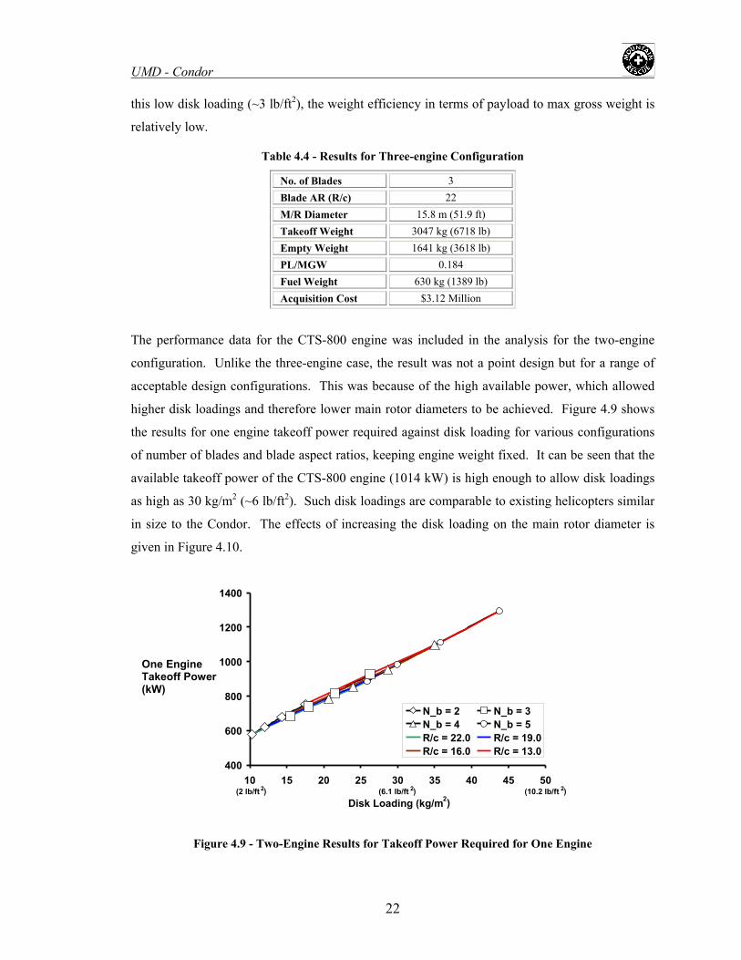
UMD - Condor
22
this low disk loading (~3 lb/ft2), the weight efficiency in terms of payload to max gross weight is
relatively low.
Table 4.4 - Results for Three-engine Configuration
No. of Blades 3 Blade AR (R/c) 22 M/R Diameter 15.8 m (51.9 ft) Takeoff Weight 3047 kg (6718 lb) Empty Weight 1641 kg (3618 lb) PL/MGW 0.184 Fuel Weight 630 kg (1389 lb) Acquisition Cost $3.12 Million
The performance data for the CTS-800 engine was included in the analysis for the two-engine
configuration. Unlike the three-engine case, the result was not a point design but for a range of
acceptable design configurations. This was because of the high available power, which allowed
higher disk loadings and therefore lower main rotor diameters to be achieved. Figure 4.9 shows
the results for one engine takeoff power required against disk loading for various configurations
of number of blades and blade aspect ratios, keeping engine weight fixed. It can be seen that the
available takeoff power of the CTS-800 engine (1014 kW) is high enough to allow disk loadings
as high as 30 kg/m2 (~6 lb/ft2). Such disk loadings are comparable to existing helicopters similar
in size to the Condor. The effects of increasing the disk loading on the main rotor diameter is
given in Figure 4.10.
Figure 4.9 - Two-Engine Results for Takeoff Power Required for One Engine
400
600
800
1000
1200
1400
10 15 20 25 30 35 40 45 50
Disk Loading (kg/m2)
N_b = 2 N_b = 3 N_b = 4 N_b = 5 R/c = 22.0 R/c = 19.0 R/c = 16.0 R/c = 13.0
(2 lb/ft 2 ) (6.1 lb/ft 2) (10.2 lb/ft 2 )
One Engine Takeoff Power (kW)

UMD - Condor
Figure 4.10 - Two-Engine Results for Main Rotor Diameter vs. Disk Loading
ves the thermodynamic efficiency and, therefore, the specific fuel
nsumption in all modes of flight. The disadvantages of higher disk loading are increased
takeoff weight, fuel weight and acquisition cost. The effects of increasing disk loading on the
two-engine results for takeoff weight is shown in Figure 4.11. It can be seen that while
increasing disk loading for a given number of blades (lowering blade aspect ratio, increasing
solidity) drives up the overall weight of the helicopter, the increase is not extreme because of the
total engine weight remaining fixed. This was found to be true of other parameters tested
including fuel weight, empty weight, and acquisition cost. It can also be seen in Figure 4.11 that
a three-bladed rotor leads to higher takeoff weight relative to four and five-bladed rotors at the
same range of disk loadings (25-30 kg/m2). In addition, there appears to be little or no difference
between the four and five-bladed configurations in terms of takeoff weight for the same disk
loading. This was o hold true for all rameters investigat sting that there
was no significant advantage in choosing a five-bladed rotor over a four-bladed rotor. A four-
bladed roto off in disk
loading and blade aspect ratio is given in Table 4.5.
It is clear that increasing disk loading decreases the main rotor diameter at a significant rate. The
original design point (3-blades, R/c = 22) yielded a diameter of over 15 m, while operating at the
maximum allowable disk loading gives a diameter of under 12 m, a much more compact design.
Higher disk loadings allows the helicopter to operate closer to the maximum rated power of this
engine, which impro
10 10 15 20 25 30 35 40 45 50
Disk Loading (kg/m )(2 lb/ft 2 ) (6.1 lb/ft 2) (10.2 lb/ft 2 )
11 12 13 14 15 16 17 18 19 20
2
N_b = 2 N_b = 3 N_b = 4 N_b = 5 R/c = 22.0
/c = 16.0 RR/c = 19.0
R /c = 13.0 Main Rotor Diameter (m)
co
found t other pa ed, sugge
r was, therefore, selected for simplicity of design and lower cost. The trade
23

UMD - Condor
24
25
30
35
5
D 2
Take
off W
eigh
t )
N_b = 2 N_b = 3N_b = 4 N_b = 5R/c = 22 R/c = 19R/c = 16 R/c = 13
(2 ( 2) 2)
00
(kg
00
0010 lb/ft
15 20 25 306.1 lb
3 40 45 50(10.22) /ft lb/ft
isk Loading (kg/m )
Figure 4.11 – Two-Engine Results for Takeoff Weight vs. Disk Loading
Table 4.5 - Blade Aspect Ratio Comparison for Two-Engine, Four-Bladed Rotor Configuration
dition of an extra passenger or paramedic to
e RFP mission requirements. A configuration with large excess installed power, however,
could significantly degrade the specific fuel consumption of the helicopter in cruise. The final
It can be seen from Table 4.5 that the gross takeoff weight, empty weight, fuel weight and
acquisition cost decrease with increasing blade aspect ratio (decreasing disk loading and solidity).
The penalties of choosing a higher disk loading (larger rotor diameter, lower solidity) are not
severe. The advantages of choosing a lower blade aspect ratio (higher disk loading and solidity)
are a smaller diameter rotor and lower excess installed power, which leads to more efficient
engine operation. Some of this excess installed power could be used to power auxiliary systems
such as a deicing system, which was not factored into the initial calculations. Some excess
available power could also be devoted to exceeding some of the requirements in the RFP, such as
an increased hover ceiling or cruise speed, or the ad
Number of Blades, Nb 4 4 4 Blade AR (R/c) 16 17.5 19 Solidity, σ 0.0796 0.0728 0.0670 M/R Diameter 11.63 m (38.2 ft) 12.05 m (39.5 ft) 12.46 m (40.9 ft) Takeoff Weight 3018 kg (6654 lb) 2964 kg (6535 lb) 2918 kg (6434 lb)
Disk Loading 29 kg/m2 (5.9 lb/ft2) 26.5 kg/m2 (5.4 lb/f2) 24.5 kg/m2 (5.0 lb/ft2) PL/MGW 0.186 0.189 0.192 Fuel Weight 602 kg (1327 lb) 580 kg (1279 lb) 562 kg (1239 lb)
OEI Power Req'd 960 kW (1287 shp) 906 kW (1214 shp) 861 kW (1155 shp)
Empty Weight 1637 kg (3610 lb) 1606 kg (3541 lb) 1580 kg (3483 lb)
Acquisition Cost $3.03 Million $2.96 Million $2.90 Million
th

UMD - Condor decision was a compromise between the two extreme cases, taking the median blade aspect ratio
of R/c = 17.5 ( 0728.0=σ
The final result of the preliminary sizing analysis was the selection of a configuration with two
CTS-800 engines and a four-bladed rotor of solidity, 0728.0=σ , and a diameter of 12.05 m
(39.5 ft).
Section 5 - Aircraft Certification
The RFP stipulates that the design solution is required to meet CFR Title 14, Part 27 or Part 29.
To this end, a certification class was selected, based on preliminary weight estimates, and steps
were taken to meet the applicable requirements of that class.
). This design reaps some of the benefits of a lower disk loading,
such as lower weight and cost, while not allowing the rotor diameter to increase significantly.
The design parameters for the two-engine and three-engine configurations are compared in Table
4.6. It can be seen that the two-engine configuration is the ideal choice and is a lighter and more
efficient design. The primary advantage of the two-engine configuration is the compactness of
the design. The three-engine case requires a rotor that is nearly 4 m (~12 ft) larger in diameter
than the two-engine case. In addition, the two-engine configuration with CTS-800 engines
possesses the potential to exceed key RFP requirements, such as HOGE and OEI ceilings,
maximum cruise speed, and load carrying capability. The reason that the final comparison
deviated so g the superior
en
Table 4.6 - nal Number of Engines Comparison
No. of Engines 2 3
reatly from the preliminary sizing results (Table 4.1) is because of
gine characteristics of the CTS-800 relative to the Model 250 (Table 4.3).
Fi
/c) 0
er 12. .5 ft) 15.8 eight 2964 535 lb) 3047 kg lb)
/h 0.3Fuel Weigh kg (12 (1389 lbt 580 79 lb) 630 kg ) Acquisition Cost $2.96 Million $3.12 Million
No. of Blades, Nb 4 3 Blade AR (R 17.5 22 Solidity, σ 0.0728 .0434 M/R Diamet 05 m (39 m (51.9 ft) Takeoff W kg (6 (6718Empty Weight 1606 kg (3541 lb) 1641 kg (2618 lb) PL/MGW 0.189 0.184 Cruise SFC 0.338 kg/kW 9 kg/kW/h
25

UMD - Condor 5.1 - Applicability
FAR regulations group all rotorcraft into two categories: Normal Category Rotorcraft and
Transport Category Rotorcraft. Normal Category Rotorcraft are required to have a maximum
eight of not more than 7,000 lb and generally have more lenient requirements for certification
igure 5.1 stinction
w
than Transport Category Rotorcraft. Transport Category Rotorcraft are further divided into two
categories. Any rotorcraft weighing over 20,000 lbs, and carrying 10 or more passengers is
required to be certified as a Category A rotorcraft. Any Rotorcraft weighing less than 20,000 lbs
and/or carrying 9 passengers or less may be certified as either Category A or Category B. Initial
sizing estimates of the Condor showed a MGW of just over 7,000 lbs. It was, therefore, decided
to design the aircraft under Transport Category requirements.
A onlyA or B+
F - Category Di s
00
0
Maximum Gross Weight (kg)
A or B A or B
Number of Passenger Seats
B+ requires some safety features of Category A
10 9
9070 1814
+
5.2 - Category A Vs. Category B
Category A rules are generally more strict than Category he main difference is that the
CFR requ
B rules. T
ires Category A helicopters to have a “stay up” capability. This is essentially the ability
climb at a rate of 30.5 m/min (100 ft/min) in forward flight after the failure of a single engine.
This obviously eliminates ategory A. Although the
takeoffs and landings from small
eliports such as city-center rooftops and oil rigs. This is a desirable feature since it vastly
proves the helicopter’s multi-mission capability. Category A helicopters are also permitted to
to
single engine aircraft from being certified as C
Condor is light enough to be certified as a Category B aircraft, a Category A aircraft has several
advantages that would improve its mission capability. For example, since Category A helicopters
have the “stay up” capability, they are permitted to make
h
im
26

UMD - Condor
reas or areas that have no emergency landing sites, where Category B fly over residential a
helicopters are not. This is an essential capability for a rescue helicopter, where the victim’s life
may depend on the aircraft’s arrival time. Being able to fly the most direct route to the rescue site
is a necessary capability for this mission profile. For these reasons, it was decided to design the
Condor for certification as a Category A Transport Rotorcraft.
5.3 - Summary of Design Requirements From CFR
Throughout the design proposal, CFR sections are referenced when pertaining to a requirement
applicable to this design. Some of the specific CFR requirements were beyond the scope of this
design proposal because of its preliminary nature and were, therefore, ignored. The following
section summarizes the main points of the 14CFR29 grouped by subparts:
Subpart A - General: This section outlines the criteria for applicability of the certification
categories.
Subpart B - Flight: This section presents the requirements for flight performan .
Incl t are weight and center of gravity limits, main rotor speed and pitch limits,
stability requirements, height-velocity envelope, which gives the flight envelope for safe
autorotation, and takeoff and landing requirements. This section stipulates the “stay up”
capability mentioned previously. Because the aircraft was designed to maintain hover at 3,658 m
(12,000 ft) with one engine inoperative, it can easily achieve a climb rate of 30.5 m/min (100
ft/min) at sea-level with one engine inoperative.
Subpart C - Strength Requirements: this section range from factor of
safety to pilot input forces and torques. It outlines the minimum loads the aircraft structure must
take for all modes of flight including hard landings and maneuvering limit loads. An important
to withstand gust loads of 17.77 knots (30 ft/sec). Because
ce of the aircraft
uded in the sec ion
Requirements presented in
requirement is that the aircraft be able
the RFP requires flight in gusts of up to 40 knots, this requirement is easily satisfied.
Subpart D - Design and Construction: This is one of the largest sections in CFR Part 29. It
outlines requirements for virtually all aspects of an aircraft design. During each segment of the
design process, Subpart D was researched for specific requirements. Among the topics in this
section are autorotational control, flutter and divergence, materials, cabin and cockpit layouts,
emergency exits, lightning and static electricity protection, and even bird strikes.
Subpart E - Powerplant: This section outlines all requirements for the powerplant system and
subsystems. Because the engines used on the Condor are existing engines that are already
certified, most of the requirements are satisfied. Subsystems of the engine system such as fuel
27

UMD - Condor
stems are also included and are
ferenced throughout the design proposal.
section provides information on the
tanks, oil system, intake and exhaust, and firewalls were designed to meet the requirements from
this section.
Subpart F - Equipment: This section deals with the equipment implemented with the helicopter
such as flight control, navigational, anti-collision, and autopilot systems. Stipulations for
electrical systems, hydraulic systems, and ice protection sy
re
Subpart G - Operating Limitations and Information: This
absolute operating limits for a certified aircraft. Included are requirements on never exceed
speed, rotor speeds, limiting height-velocity envelope, as well as safety equipment information.
Section 6 - Main Rotor & Hub Design
6.1 - Baseline Rotor Design
The main rotor for the Condor was designed for efficient hover at high altitude and good high
speed, high altitude cruise performance. The two modes of flight often carry very different
requirements, creating the need for design compromises. The rotor diameter, number of blades
and solidity were previously selected in the preliminary sizing study (See Section 4). Table 6.1
lists the key design parameters for the main rotor.
Table 6.1 - Main Rotor Design Parameters
Diameter 12.05 m (39.5 ft) No. of Blades 4 Blade Chord 0.34 m (1.1 ft)
Sweep 20 deg (from 94%) Anhedral 20 deg (from 96%) Taper 10% (from 94%)
Twist -12 deg (linear)
Tip Speed 210 m/s (690 ft/s)
6.1.1 Blade Twist
A negative blade twist is beneficial during hover because it redistributes the lift distribution
inboard of the blade tips. This tends to reduce the induced power and hence, increases the figure
of merit of the rotor [Leis00]. Blade twist also tends to delay the onset of stall on the retreating
blade at high speeds. Too much twist, however, degrades blade performance on the advancing
side of the disk in high speeds by creating negative lift near the tips. Both modes of flight were
important for the design of the Condor. Therefore, a moderate linear blade twist of -12 degrees
was selected as a compromise between the hovering and forward flight performance.
28

UMD - Condor 6.1.2 Airfoil Sections
The selection of airfoil sections is critical to the rotor performance. The Condor is required to fly
numbers are needed. Unfortunately, these are
e hub loads and control loads to acceptable levels. To fulfill these requirements, two advanced
airfoil sections were sel C(6) airfoil sections.
ith low pitching moments [Noon90] and it is used from 0-90%
in the public domain.
6.1.3 Tip Speed
at high speeds at high altitudes, making stall and compressibility effects key issues. To delay the
onset of stall on the retreating blade, airfoils with high lift to drag ratio and maximum lift
coefficient should be used. To prevent the onset of compressibility effects on the advancing side,
airfoils with high drag divergence Mach
conflicting requirements, making it necessary to use multiple airfoil sections over the span of the
blade for the best performance. Another desirable characteristic for rotor airfoil sections is that
the slope of the pitching moment versus angle of attack (AOA) curve be small in order to keep
th
ected for the Condor, namely the NASA RC(4) and R
The RC(4) is a high lift airfoil w
span. The RC(6) is a supercritical airfoil section with a high drag divergence Mach number and
good maximum lift capability at high speeds [Noon91]. The RC(6) is used from 90% span to the
tip. These particular state-of-the-art airfoils were selected, in part, because of their readily
available aerodynamic characteristics. Unlike the advanced airfoils developed by manufacturers,
these airfoils and their characteristics are available
The selection of tip speed icant e ect on the performance of a helicopter rotor.
Higher tip speeds help to del of retre tall in forward flight. Also a high tip
speed allows for good autorotative performance. However, a very high tip speed also promotes
compressibility effects on th ing blade e ard speeds and lead to problems
of noise [Leis00]. In additio er tip speeds centrifugal forces generated by the
lades, which increases hub weight. In light of these problems and the fact that retreating blade
with blade twist and advanced airfoil sections, a nominal tip speed of 210 m/s
has a signif ff
ay the onset ating blade s
e advanc ven at lower forw
n, high lead to higher
b
stall can be delayed
(690 ft/s) was selected for the Condor.
6.1.4 Tip Geometry
A planform sweep of 20 degrees, starting at the 94% span was selected to minimize
compressibility effects to cruise speeds of over 170 knots at 3,658 m (12,000 ft). A moderate
amount of taper of 10% was also used beginning at the 94% span in order to increase the figure of
merit by offloading the blade tips. In addition, 20 degrees of anhedral was used starting at the
29

UMD - Condor
e Sikorsky growth blade tip used on the Blackhawk. Again, anhedral is 96% span, similar to th
used to boost the figure of merit by a modest amount.
6.2 - Swashplateless Rotor Control
6.2.1 - Trailing Edge Flaps
The primary flight control in a helicopter is achieved by controlling the rotor thrust vector, which
in turn is accomplished by changing the blade pitch as a function of blade azimuth. This can be
achieved by two different mechanisms. One approach makes use of a swashplate to change the
blade pitch. This is normally achieved by tilting the plane of the stationary part of swashplate
system through the use of servo actuators. The other approach involves the use of servo-flaps
located at the trailing edge of the rotor blade. Deflecting the servo-flaps in collective and cyclic
modes changes the aerodynamic loads over the blades, introducing elastic twist in the blades. To
have good flap effectiveness, the blades need to be soft in torsion, which can be achieved with a
soft torsional spring (tension-torsion strap). The overall actuation force required for a swashplate
system to change the blade pitch is significantly higher than what is required to produce desired
flap deflection in a swashplateless system [Chop02]. Consequently, the regular swashplate
system is bulky, heavy, mechanically complex and causes a large parasite drag. A swashplateless
esign is lighter, mechanically simple, and offers up to 15% reduction in parasite drag [Shen03],
aintenance, improved performance, increased payload ratio and decreased
some of these problems. A rotor with integrated trailing
dge flaps has better aerodynamic performance than auxillary servo flaps (i.e., plane flaps) and
tios. In addition, it has been demonstrated that such flaps can also be used
Because of the enormous potential of embedded flaps, major helicopter manufacturers are
investigating possible incorporation of this technology in their aircraft. Boeing has conducted
d
enabling easy m
maintenance costs. However, it requires a compact actuation system.
Kaman has been using the servo flaps as primary control devices in their helicopter for more than
50 years [Wei03]. However, an external trailing edge flap system causes some additional drag
penalty because of exposed surfaces. The presence of external flaps move the sectional center of
gravity to aft positions, hence large ballast weights are required to bring the blade sectional c.g.
forward to an acceptable position, resulting in additional overall blade weight penalties. Using an
embedded trailing edge flap eliminates
e
superior lift-to-drag ra
efficiently for individual blade tracking, and active vibration and noise suppression [Roge02],
[Roge04], [Shen03], [Strau04].
30

UMD - Condor
ge flaps actuated with piezostack actuators.
has been established that the use of smart material actuated flaps offers significant performance
y, as well as Kaman are also examining incorporation of
ntrol in their forthcoming designs.
the application of a cyclic differential voltage over the blade span. Such a design requires
(iii) Blade pitch control - individual blades are actuated using hydraulic or smart material
actuators in the rotating frame. Hydraulic actuation requires a complex hydraulic slip ring,
extensive tests to evaluate performance of smart material actuators; and more recently performed
whirl tower tests of the full scale rotor with trailing ed
It
and vibration benefits [Strau04]. Sikorsk
this technology for primary co
In light of these recent technological developments, a swashplateless rotor with a trailing edge
flap actuated by a compact piezo-hydraulic actuator for primary and vibration control was
selected for Condor. The design team is quite aware of various methodologies that have been
attempted as a replacement for the swashplateless system. A brief discussion of these is
presented below.
(i) Blade camber control - achieved by cyclic excitation with embedded material with different
arrangements on top and bottom surfaces of the blade sections. Because of the lack of
availability of suitable smart materials with sufficient stroke and stiffness to produce
desired deformation, this concept was found to be infeasible [Dado82], [Strau95].
(ii) Blade twist control - enables blade twist to be generated from embedded active materials by
large actuation power and the structural integrity of the blade is compromised [Buet01].
whereas smart actuation is limited by a relatively small stroke [Ham83], [Chop00].
(iv) Tilting shaft concept - the control mast is tilted to control the rotor thrust vector.
Unacceptably large actuation force and stroke requirements make this concept infeasible for
full-scale rotors [Hous98].
6.2.2 - Lift Flaps vs. Moment Flaps
Lift Flaps
When the flaps are used to enhance lift on the torsionally stiff blades (νθ
ar to the effect of changing blade pitch. The primary effect of
such flaps is to change the lift characteristics of the blade without significantly affecting the
> 4/rev), the deformation
due to aerodynamic pitching moments is negligible and the only effect of the flaps is to increase
the sectional lift, which is simil
pitching moment characteristics of the blade or the blade pitch dynamics. These flaps are referred
to as lift flaps and have significantly large chord (> 35% of blade chord) to increase their
31

UMD - Condor
Moment flaps on the other hand are smaller in size (< 25% blade chord) and are used with
θ
rements with lift flaps [Shen03a], and they have been used by Kaman for over
50 years for primary control purposes, as external servo flaps. Because of their smaller size,
lower
Cond
6
efficiency. The amount of deflections required by such flaps is relatively large and consequently
results in higher drag, stalled blades and degraded rotor performance. Further, to actuate such
flaps for primary controls, large stroke actuators are needed, which is often prohibitive with the
currently available smart materials.
Moment Flaps
torsionally soft blades (ν < 2/rev). These types of trailing edge flaps are considered to be more
effective in changing the pitching moment of blade section with only a small change in sectional
lift characteristics. The induced pitching moment from flap deflection results in a twisting of the
blade. The flap deflections required for achieving the primary control using moment flaps is small
compared to requi
deflections requirements and lower drag penalty, integral moment flaps were chosen for the
or’s rotor design.
.2.3 - Details of Moment Flap Design
ey parameters that influence the performance of trailing edge flaps are the blade torsional
ency, pitch indexing angle, flap size, spanwise location, and chordwise aerodynamic bala
The k
frequ nce
mode
for a armonic
where deflection and δc is the maximum cyclic flap amplitude. A
arametric study was carried out for a flap chord of 20% blade chord to determine the optimum
n requirements [Shen03], [Shen03a], [Ormi01]. Figure 6.1
a blade with low torsional stiffness decreases the trailing edge flap deflection
[Shen03], [Shen03a], [Ormi01]. To investigate the effect of these parameters, a mathematical
l was developed using a propulsive trim model of a helicopter with active trailing edge flaps
level flight condition. The coupled pitch-flap equations were solved using the h
balance method. The pitch inputs were defined as:
δ(ψ) = δo + δ1c cosψ + δ1s sinψ, δc = (δ1c2+δ1s
2)1/2 and |δ| = δo+δc
|δ| is the maximum flap
p
flap configuration for the current desig
shows that
requirements. Blades with very low torsional frequency (< 1.7/rev), however, are prone to
aeroelastic instabilities, such as pitch-flap flutter and pitch divergence. Torsional frequencies
close to 2/rev may lead to resonance condition and torsional frequencies greater than 2/rev require
large flap deflections and actuation power. The optimum frequency lies between the two
extremes, therefore a torsional frequency of 1.8/rev was chosen for the rotor blades of the current
design.
32

UMD - Condor
33
The flap deflections required to achieve trim at high speeds are relatively large (Figure 6.1),
therefore the blade pitch needs to be indexed. The blade pitch index angle defines the three-
quarter radius blade pitch value relative to the hub plane. Pitch index angle is normally selected
to be higher than the collective pitch required to trim the helicopter at a selected forward speed.
This is done to ensure that positive collective flap deflection is required at all speeds. A
downward flap deflection increases lift on the blade, moving the blade airload distribution
inboard, and improving the rotor performance.
Figure 6.1 - Maximum Flap Deflection For Level Flight (flap chord = 0.2C)
Figure 6.2 - Blade Pitch Angles Required to Trim (Conventional Swashplate System), Zero Twist
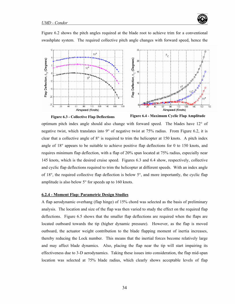
UMD - Condor
igure 6.2 shows the pitch angles required at the blade root to achieve trim for a conventional
ashplate
optimum blades have 12° of
egative twist, which translates into 9° of negative twist at 75% radius. From Figure 6.2, it is
nots.
.2.4 - Mome
F
sw system. The required collective pitch angle changes with forward speed, hence the
pitch index angle sho speed. The
Figure 6.3 - Collective Flap Deflections Figure 6.4 - Maximum Cyclic Flap Amplitude
uld also change with forward
n
clear that a collective angle of 8° is required to trim the helicopter at 150 knots. A pitch index
angle of 18° appears to be suitable to achieve positive flap deflections for 0 to 150 knots, and
requires minimum flap deflection, with a flap of 20% span located at 75% radius, especially near
145 knots, which is the desired cruise speed. Figures 6.3 and 6.4 show, respectively, collective
and cyclic flap deflections required to trim the helicopter at different speeds. With an index angle
of 18°, the required collective flap deflection is below 5°, and more importantly, the cyclic flap
amplitude is also below 5° for speeds up to 160 k
6 nt Flap: Parametric Design Studies
namic overhang (flap hinge) of 15% chord was selected as the basis of prelim
is. The location and size of the flap was then varied to study the effect on t
Figure 6.5 shows that the smaller flap deflections are required w
located outboard towards the tip (higher dynamic pressure). However, as
actuator weight contribution to the blade flapping moment of
ing the Lock number. This means that the inertial forces beco
affect blade dynamics. Also, placing the flap near th
due to 3-D aerodynamics. Taking these issues into co
selecte ac
A flap aerody inary
alys he required flap
eflections. hen the flaps are
the flap is moved
outboard, the inertia increases,
thereby reduc me relatively large
d may e tip will start impairing its
fectiveness nsideration, the flap mid-span
cation was ceptable levels of flap
an
d
an
ef
lo d at 75% blade radius, which clearly shows
34

UMD - Condor
requirements increase with the flap span. A flap span of 0.2R was selected as the optimum size.
deflections. Figure 6.6 shows that having a larger flap span is desirable, but hinge moment
The details of the final optimized configuration are shown in Table 6.2. The final configuration
consists of two flaps each consisting of 10% of the rotor radius. A dual flap design was chosen to
provide additional redundancy in the control system as well as low actuation requirements per
flap. In case of the failure of one of the flap actuators, the other flap should be able to trim the
helicopter in all normal flight conditions. The hinge moments (steady component HMo and cyclic
components HM1c and HM1s) and blade deflections required for trim are shown in Figures 6.7 and
6.8, respectively. The results displayed in these figures are a clear indication of the superior
performance provided by the proposed configuration.
Figure 6.5 - Effect of Varying Flap Location (Flap Length 0.2R)
Figure 6.6 - Effect of Varying Flap Size(Flap Location 0.75 R)
Table 6.2 - Swashplateless Roto
Torsional frequency (rotating) 1.80 / rev Lock number (sea-level) 9.45
Flap chord 20% blade chord
Flap spanwise location 1st flap 65-75%;
Blade sectional pitching moment coefficient -0.006 Blade twist -12 degrees Pitch index angle at the blade root 18 degrees
r Design Parameters
Parameter Value
Blade feathering moment of inertia 6.54x10⁻⁴
2nd flap 77-87%
35

UMD - Condor
6.3 - Compact Flap Actuator
To me ts for prim
the flight envelope, a compact flap actuator was designed to be embedded in the rotor blade.
et the cyclic and collective flap requiremen ary control of the rotor throughout
6.3.1 - Actuator Design
From the flap analysis carried out in the previous section, it was determined that a flap angle
range of ±5° would be sufficient to meet cyclic control requirements. Based on a 25 mm offset
hinge, this leads to the requirement of an actuator output displacement of ±2.5 mm about the
neutral point. In addition, the hinge moment requirements lead to an actuator output force of
about 111.25 N (25 lb) per actuator, using two actuators per flap. With a rotor RPM of 333, the
actuator output frequency required for primary rotor control is about 5.5 Hz. Using these
quirements, smart materials were compared for use as the flap actuator in Table 6.3.
Table tuation
Smart Material Maximu ked ce Bandwidth Evaluation
re
6.3 - Comparison of Potential Smart Materials for Ac
m BlocStrain For
loy High (8%) Band
High heavy; insu
Low (0.1%) 0 Low oper
(0.2%) Moderate H Magneti
Low Low (~45 N Bloc
Shape Memory Al High Low (<1 Hz) width too low for primary control
Magnetic Shape Memory Alloys (6%) Low High (~1
kHz) Magnetic coils are large and
fficient blocked force
Electrostrictives Moderate (~2500 N)
High (<10kHz) ating temp. (<40°C)
Magnetostrictives Low (~2500 N) igh (<10 kHz)
c coils are large and heavy
Piezobimorphs (0.13%) ) High (<100 kHz) ked force insufficient
Piezostacks Low (0.1%) High (~4500 N)
High (<100 kHz)
Requires stroke amplification method
Figure 6.7 - Flap Hinge Moment Figure 6.8 - Flap Deflections for Trim
36

UMD - Condor Piezostacks were selected as the best smart material for use in the flap actuator because of their
high blocked force and bandwidth capabilities. In addition, they do not incur the same weight
penalty as magnetostrictive actuators. Magnetostrictives require large coils to produce the
magnetic fields needed to actuate the material. Piezostacks are actuated with an input voltage,
and therefore, only need electrical wires for actuation. Because the maximum strain of
piezostacks is relatively small, it was necessary to use some type of stroke amplification method.
A piezo-hydraulic hybrid pump, recently developed at the University of Maryland was used to
amplify the small stroke actuation of the piezostacks [Siro03], [Elli04]. The working principle of
the pump is based on frequency rectification of the high frequency, low stroke actuation energy of
piezostac oke hydraulic ou
create an enormous amount of energy. The fluid is used to
uid source. The mechanics of the actuator parts are shown in Figure 6.9:
ks into low frequency, large str tput energy. When actuated at high
frequencies (>1 kHz), piezostacks
transmit the energy of the piezostacks to a hydraulic output cylinder. Because the fluid in the
pump is self-contained, the actuator is compact and does not require hydraulic lines to provide a
fl
Figure 6.9 - Piezo-hydraulic Flap Actuator
Piezostacks - Eight piezostacks with dimensions of (10 mm × 10 mm × 18 mm) are enclosed in
an aluminum casing along with a piston and diaphragm assembly. One end of the piezostacks is
fix casing while the other end m with the pist AC voltage
(< 1 d to tacks at a high freq Hz) cy,
small amplitude fluid displacements p then rectified by
magnetorheological (MR) valves.
MR Valves - MR valves are used in th uator for both frequency rectification and output
directional control. The lves oducing a small mag king
fluid p. B fl th R F
ed to the aluminum akes contact on. An
10 V) is applie the piezos uency (~1 k , producing high frequen
in the pum ing chamber which are
e flap act
MR va work by pr netic field in the wor
of the pum ecause the uid used in e pump (M luid 132 80) has magnetic
37

UMD - Condor
e phase of the valves by 180°. Note: mechanical reed valves were successfully applied initially
properties, its exposure to a magnetic field increases its local viscosity, effectively blocking the
valve. The valves are always kept in opposite states and are switched at the same frequency as
the piezostacks. So, when the piezostacks expand, fluid is pushed out of the pumping chamber
through Valve A. The valves then switch states, and as the piezostacks contract, fluid is pulled
into the pumping chamber through Valve B. This frequency rectification process creates a
constant flow direction to the output cylinder. The output direction is changed by simply shifting
th
[Elli04] before implementing MR valves [Yoo04].
Output Cylinder - The output cylinder used to actuate the flap has a bore diameter of 14 mm and
is 75 mm long. It is a single acting cylinder with a piston rod diameter of 6.5 mm.
Accumulator - The accumulator is used to apply a pre-pressure to the working fluid of the pump
so that it is insensitive to air entrained in the fluid.
6.3.2 - Actuator Mounting and Operation
The entire actuator assembly is placed behind the blade spar. The heaviest component of the
assembly, the pump and MR valve assembly, is rigidly attached to the blade spar. This keeps the
chordwise center of gravity of the blade as far forward of the aerodynamic center as possible,
reducing the likeliness of blade flutter. The complete actuator assembly weighs about 0.45 kg.
The output cylinder is mounted on a support rib in the chordwise direction. The output piston rod
is connected to the flap hinge tube using a pitch horn. The flap hinge tube is connected to the
blade using two flange mounted roller bearings on each side. A panel above each actuator is
provided to allow easy access to the assembly. The panel is secured using countersunk screws so
that the complete assembly fits within the airfoil contour.
ion at the 3, 4, and 5 per rev frequencies. Such a pump has
Cyclic and collective output displacements from the piston rod are translated into cyclic and
collective flap deflections. The system uses a feedback signal from a potentiometer mounted on
the flap hinge tube to determine the exact position of the flap. Estimated power required for
primary control is about 45 W per actuator, or 180 W per blade. Because the actuator can provide
output frequencies of up to 4 times that required for primary control, there is the possibility of
using the flap for vibration reduct
already been fabricated and tested under a wide range of load conditions for both static and
dynamic loads.
38

UMD - Condor 6.3.3 - Safety and Monitoring
The compact piezo-hydraulic pump contains no moving parts and is therefore, extremely reliable.
To provide extra redundancy, two actuators are provided for each flap. If one actuator fails, the
second actuator has enough authority to execute primary controls and trim the rotor in level and
descending flight modes. Strain gauges mounted on the piezostacks of all the actuators will alert
the pilot and the HUMS if the system is not functioning properly. In the case of engine failure,
the flap actuators are designed to immediately position the flap at the optimum angle to allow
rapid entry of the rotor into autorotation as stipulated by 14CFR29.691. The actuator has the
ability to provide mean displacement beyond the normal requirements to allow a higher collective
for flare when performing an autorotational landing.
6.4 - Slip Ring
Power is supplied to the flap actuators by the electrical system in the helicopter (see Section
electrical power from the non-rotating frame to the 12.2.7). It is, therefore, necessary to transfer
rotating frame. A slip ring, consisting of stationary housing and brushes in contact with a rotating
slip ring, is used for this purpose. Because small dust particles can disrupt contact between the
brushes and the slip ring, multiple sets of “long-life” brushes and rings are used. This ensures
that power to the actuators will not be lost because of a single loss of contact. Contactless
magnetic slip rings were considered an infeasible technology for certification at this point in their
development.
6.5 - Blade Structural Design
The blades of Condor were designed to accommodate the flaps, actuators and related hardware,
d provide low vibrations using tailored composite blades [Bao04]. The blades have aft c.g. an
limits imposed by the 14CFR29.629 requirements to avoid pitch-flap flutter and pitch divergence.
This is particularly important, as the blades were designed to be soft in torsion to achieve desired
flap effectiveness for the swashplateless system. The foreword c.g. limits are imposed by the
nose down pitching moments generated by the main lifting section of the blade.
6.5.1 - Blade Design Details
The use of composite materials in blade manufacturing gives the designer flexibility in tailoring
the properties of the blade to meet the stress requirements. In addition, specific elastic coupling
n be introduced. Wind tunnel tests on Mach scaled composite tailored rotors of the UH-60 ca
39

UMD - Condor
duced the 4/rev vibratory hub loads, a key
urce of vibrations in a four bladed rotor. Tests show that vertical hub forces were reduced by
ne hub forces were reduced by up to 3%, and the head moment was reduced by
75% R
Black Hawk with flap-bending/torsion coupling have demonstrated significant effect on the fixed
frame vibratory rotor hub loads. A composite rotor with a dual spanwise segmented flap-
bending/torsion coupling (FBT-P/N) significantly re
Negative Coupling Positive Coupling
Figure 6.10 - Layup of Composite Tailored Blade
so
up to 15%, in-pla
up to 14% [Bao04]. The blades used on the Condor make use of this technology to minimize
vibration (Note that Sikorsky is also investigating this technology for their current and future
rotor systems). The blade structure (refer to Foldout 6.1) consists primarily of a D shaped spar
and a skin made out of ±45° graphite epoxy weaver. The FBT coupling is introduced in the D-
spar which is made of 26 plies of 0.005 inch graphite epoxy composite. The blade has negative
FBT coupling for up to 75% of blade radius and positive FBT coupling beyond 75% (Figure
6.10). Preliminary estimates suggest an unbalanced ply layup, as shown in Figure 6.11.
[-20]6 Transition Region
[45/-45] 4Root Tip [0]3
Figure 6.11 - Spanwise Ply Layup for D-Spar
Blade Blade
[20]6
40
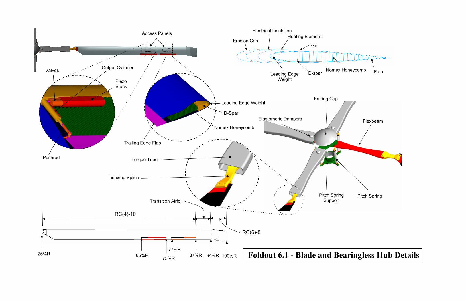
Foldout 6.1 - Blade and Bearingless Hub Details
Access Panels
Torque Tube
Stack
Trailing Edge Flap
Pushrod
Indexing Splice
Piezo
Nomex Honeycomb
D-Spar
Output Cylinder Valves Nomex Honeycomb Flap D-spar
Skin
Heating Element Electrical Insulation
Erosion Cap
Leading Edge Weight
RC(6)-8
Pitch Spring
Elastomeric Dampers
Fairing Cap
Flexbeam
Pitch Spring Support
25%R R 94%RR 87%65% 100%R
RC(4)-10
75%R
77%R
Transition Airfoil
Leading Edge Weight

UMD - Condor
42
A typical section has six unidirectional sub-laminates for axial & bending stiffness, four balanced
([45/-45]) sub-laminates for shear stiffness, and remaining twelve layers to introduce desired
coupling. An optimized ply layup may be further refined using a more detailed analysis
[Gang94]. Tungsten mass ballast weights were used in the inner nose cavity of the blade to move
the center of mass of the blade forward to the quarter chord location. Erosion strips are mounted
ov de leading edge and ele ating element (de-icing blanket) is placed
beneath the erosion strip. The remaining internal blade structure is made of Nomex honeycomb
since it bonds well with the skin and has ble 6.4 summarizes the
properties of the primary structural materials used in the design of the blades.
6.5.2 - Lightning Protection and Electromagne
er the bla ctrically insulated he
low moisture absorption. Ta
tic Shielding
Helicopter blades are required to withstand a 200 kA lightning strike and still permit the
helicopter to land safely [Alex86]. Lightning strikes may cause delamination in the composite
spar due to high heat, and the large current flow could damage the actuators. To protect these
components, blade sections that are susceptible to heating and large currents are covered
externally with doublers made of con at conduct the current to a titanium
abrasion strip. The current flows spanwise to the root end attachment of the blade to avoid any
electrostatic charge build up. The actuator housing is wrapped in a nickel/iron alloy foil to shield
it from stray low frequency electromagnetic signals. The desi equirements
stipulated in 14CFR29.610 for lightning and static electricity protection.
6.6 - Hub Design
ductive materials th
gn conforms to the r
The hub for the Condor was designed to ensure low aerodynamic drag, low weight, structural
simplicity, and superior handling qualities. The trailing edge flap design imposes low torsional
stiffness of the rotor blades to ensure adequate flap effectiveness. Hence a bearingless soft in-
hub was selected, which ensures greater control power and therefore better handling
qualities than articulated designs [Prou89]. A soft in-plane hub design cted to
in-plane loads.
Table 6.4 - Properties of Materials Used in Blade Structure
Material Density (lb/in3)
Young’s Modulus (msi)
Shear Modulus (msi)
Nominal ply thickness (in)
plane
was sele minimize
±45° Graphite epoxy 0.055 2.1 4.55 0.018 Nomex Honeycomb 0.00116 0.0105 0.0042 -
Tungsten 0.70 40 19.2 -

UMD - Condor
The bearingless hub for the Condor (refer to Foldout 6.1) has four primary elements: a flexbeam
(through which flap, lead-lag, and pitch motions are achieved), a torque tube (for the blades to
react against the pitch spring), an elastomeric damper (to provide lead lag damping), and a pitch
spring (low frequency adapter).
Flexbeam - The flexbeam was tailored to the required stiffness and structural properties, and
provides virtual flap and lead-lag articulations. The flexbeam is cantilevered to the hub support
structure at one end and is bolted to the pitch indexing splice at the other end. The flexbeam is
fabricated from uni-directional S-glass/epoxy tapes. The length of the flexbeam is 20% of blade
radius.
Torque Tube - The torque tube in this design reacts against the pitch spring and elastomeric
damper, instead of transmitting the pitch input as is done in a conventional design. The torque
tube is fabricated from carbon fiber filaments to which uni-directional tape is added to provide
high chordwise stiffness.
Pitch Spring - The pitch spring or frequency adapter is a soft compression spring that was
designed to adjust the fundamental torsional frequency of the blades to 1.8 /rev. It carries the
1/rev oscillatory loads and provides reaction forces to achieve required pitch angles for trim of
the helicopter. The stiffness of the spring was calculated using UMARC and was designed to
allow a maximum blade pitch of ±20o. The spring parameters are presented in Table 6.5.
Elastomeric Damper - Because the soft in-plane hub design was selected, lead-lag damping is
required to avoid ground and air resonance. Therefore, a Silicone-rubber elastomeric damper
consisting of alternate layers of elastomer and metal shims was used to augment lead-lag
damping. These dampers have long service life, high reliability, low maintenance/inspection
requirements, and are effective in temperatures from -65oF to +200oF [Lord04].
Length (mm)
Turns Coil d(m
210 20 4
6.7 - Autorotation Charact
All helicopters are required
Autorotation capabilities of a
autorotative index. A compari
autorotative index, which is de
Table 6.5 - Spring Design Details
43
iameter m)
Coil wire diameter (mm)
Ultimate fatigue shear stress (GPa)
Shear Modulus (GPa)
5 4.8 0.35 82.7
eristics
to demonstrate autorotation capabilities for CFR certification.
new design can be compared with existing helicopters using an
son of the current design to existing helicopters using the Sikorsky
fined as the kinetic energy of the main rotor divided by the product

UMD - Condor
of gross weight and disk loading, is given in Table 6.6. It is clear that the Condor will have
excellent autorotation characteristics with an index of nearly twice that of the S-76A.
Helicopter GTOW (kg)
Condor 3,343 S-76A 4,672
SA365N 4,000
6.8 - Active Vibration C
Vibration is a serious probl
loads. Vibration inducing
complex wake structure, co
blades (tracked rotor), only
to fixed frame (Nb is the n
identical, non-kNb/rev harm
overcome this problem blad
cost. Further, to minimiz
leading to high manufactu
composites to suppress kN
completely minimize vibrat
IBC involves the calculatio
the kNb/rev and non-kNb/re
loads are measured in fixed
hub loads are sampled for o
which involves the calculat
flap deflection on each bla
control inputs can be determ
loads and flap control angle
methodology was adopted
algorithm designed to up
measurement. The controll
per rev basis. It performs b
Table 6.6 - Autorotation Index Comparison
44
Polar moment of inertia (kg-m2)
Rotor speed
(RPM)
Disk loading (N/m2)
Autorotation index (m3/kg)
941 333 255 1.34 2,562 293 333 0.77 2,091 349 360 0.97
ontrol
em in all helicopters and the main rotor is a key source of vibratory
oscillatory airloads are caused by a highly unsteady flow field,
upled blade motion, and time-varying blade pitch inputs. For identical
kNb/rev harmonics of blade loads are transferred from rotating frame
umber of blades, k is an integer). However, if the blades are not
onics (mainly 1/rev) are also transferred to the fuselage. Currently, to
es need to be tracked periodically resulting in a significant operating
e blade dissimilarities, tight manufacturing tolerances are imposed
ring cost. The blades of the Condor have been tailored using
b/rev vibrations using flap-bending-torsion coupling. However, to
ions and suppress non-kNb/rev loads as well IBC is used.
n of optimal control input for each blade separately to minimize both
v loads. To achieve the control of individual blades, the rotor hub
frame in real time. Once the steady-state has been established, the
ne revolution and the system identification is performed (Figure 6.12),
ion of uncontrolled hub forces, and transfer matrix (which relates the
de to hub loads). Once the state estimates are obtained, the optimal
ined by minimizing a performance function involving vibratory hub
s (higher harmonics). A robust Kalman filter based adaptive control
to implement IBC [Roge04]. This is a computationally efficient
date parameter estimates recursively on the basis of a single
er is implemented by sampling the hub loads and control inputs on a
oth vibration reduction and system identification in real time.

UMD - Condor
for active
ibration control and in-flight tracking.
A flap located outboard of the blade (at 77-87% of blade radius) was employed for this purpose in
present design because it has better flap effectiveness (refer to Section 6.2.4). Recent wind tunnel
tests conducted in the Glenn L. Martin wind tunnel on Mach scaled rotors revealed that flap
deflections of 2.8° or less were sufficient to reduce the 3, 4 and 5/rev harmonics of root flap
bending moments by 40%, 91%, and 91%, respectively, when targeted alone [Roge04], [Roge02].
This, and previous wind tunnel tests, demonstrated the robustness of this time-domain IBC
control methodology. Significant 1/rev vibration reduction was also demonstrated. Therefore, the
trailing edge flaps of the Condor will not only be used for primary control but also
in Fixed Frame
v
6.9 - Rotor Dynamics
The main rotor system is soft inplane bearingless design with blades that are soft in torsion.
Hence, its dynamics characteristics were carefully examined to ensure proper frequency
placement to avoid aeromechanical instabilities.
6.9.1 - Dynamic Analysis
The fan plot was obtained by using UMARC. The blade was modeled using 13 finite elements
for the blade, 4 finite elements for the flexbeam, and 3 elements for the torque tube. The blade
and flexbeam stiffness were optimized to appropriately place the blade frequencies. The blade
stiffness and mass distribution is shown in Figure 6.13. The small spike in the blade mass
distribution in the outboard section is due to the presence of the piezo-hydraulic actuators,
Update System
Identification
Update Optimal
Hub Loads Measurements
Signal conditione
Rotor in wind tun
rsnel
Power amplifiers
Figure 6.12 - Scheme for Active Vibration Control
45

UMD - Condor
provided for flap deflection. The rotor frequencies are well separated as seen from the fan plot
(see Figure 6.14). The first six natural frequencies are given in Table 6.7.
6.9.2 - Aeroelastic An
To ensure that the roto
carried out. A pitch-fl
avoid pitch-flap flutter
from the leading edge
0
0.001
0.002
0.003
0.004
0.005
0.006
0 0.2
Non Dimensio
GJ/
(m0Ω
2 R4 )
0
0.0005
0.001
0.0015
0.002
0.0025
0 0.2Non Dimensiona
EI y/
(m0Ω
2 R4 )
s
Table 6.7 - Main Rotor Blade Natural Frequencie46
Mode Flap Lag Torsion First 1.04 0.65 1.80
Second 2.76 4.15 - Third 4.68 - -
alysis
r is free from any aeromechanical instability, an aeroelastic analysis was
ap flutter analysis (see Figure 6.15) indicates that the critical c.g. offset to
and pitch divergence, is aft of the quarter chord at nearly 28% of the chord
. Ballast weights were used in the blade tips to move the c.g. ahead of
0
0.2
0.4
0.6
0.8
1
1.2
1.4
1.6
0 0.2 0.4 0.6 0.8 1
Non Dimensional Spanwise Location, r/R
m/m
o
0.4 0.6 0.8 1
nal Spanwise Location, r/R
0
0.01
0.02
0.03
0.04
0.05
0.06
0.07
0.08
0.09
0 0.2 0.4 0.6 0.8 1
Non Dimensional Spanwise Location, r/R
EIz/(
m0 Ω
2 R4 )
0.4 0.6 0.8 1l Spanwise Location, r/R
Figure 6.13 - Blade Stiffness & Mass Distribution
Torque Tube
Flexbeam

UMD - Condor
ure 6.17) and all rotor
odes were found to be
6.9.3 - Ground & Air Resonance
quarter chord to 22% of chord. This provides adequate margin to avoid pitch-flap flutter and
divergence. A comprehensive aeroelastic analysis was carried out (see Fig
m stable over the entire flight regime.
Because the Condor rotor is a sof an ring ss des n, a ground resonance analysis was
erformed. It can be seen from the Figure 6.16, that all the modes, including rotor in-plane
modes, are stable and adequately damped. Soft in-plane rotors are also susceptible to air
resonance which occurs due to interaction of rotor flap and lag m
roll modes. A comprehensive air resonance analysis was perfor
be seen that the rotor lag mode remains stable even mper at all
advance ratios. The inclusion of the elastomeric dampers would f ent the stability of
the lag modes.
t in-pl e bea le ig
p
odes with the fuselage pitch and
med (see Figure 6.18), and it can
in the absence of elastomeric da
urther augm
Figure 6.14 - Rotor Fan Plot Figure 6.15 - Pitch Flap Flutter/ Divergence Stability Boundary
Figure 6.16 - Ground Resonance Analysis
47

UMD - Condor
48
Figure 6.17 - Flap/Lag/Torsion Analysis
Section 7 - Fan-in-Fin Anti-Torque System 7.1 - Anti-Torque System Trade Study
The configuration of the anti-torque system was decided after a trade study between the
conventional tail rotor and the fan-in-fin concept.
Safety on ground and in flight - Because the Condor is designed as a mountain rescue helicopter,
operational safety is of prime concern. The exposed, and often unseen rotor blades of a
conventional tail rotor are potential hazards for people on the ground, while a fan-in-fin design,
with a protective duct around the rotor, is safer and more visibly apparent. Additionally, for the
same thrust capability, a fan-in-fin design usually needs about half the disk area of a conventional
tail rotor. This is an important consideration in rescue operations because greater usable space
around the helicopter means faster and safer unloading of patients. The duct around the fan
prevents the tail rotor blades from striking obstacles such as mountain ledges or tree branches
during flight operation in confined spaces.
Maneuverability - A mountain rescue helicopter needs to have sufficient yaw maneuverability
and handing qualities for negotiating turns in tight spaces and withstanding high sidewinds. A
fan-in-fin design is expected to have both of these qualities. The RFP requires capability of the
helicopter to maintain heading with a cross wind of 40 knots from any azimuth. Cross winds
directed against the downwash of the tail rotor are the most critical design conditions. If the ratio
of crosswind to induced velocity of the tail rotor is high enough, there is a possibility of vortex
ring state developing. Typically, fan-in-fin designs operate at higher induced velocities than
conventional tail rotors designed for the same thrust capability. This means that a fan-in-fin
design needs a higher side wind to induce vortex ring state than a conventional tail rotor.
Figure 6.18 - Air Resonance Analysis

UMD - Condor Furthermore, the structure surrounding the fan prevents the establishment of air re-circulation,
thus delaying the onset of the vortex ring state [Moui86].
Hover efficiency - From momentum theory, a fan-in-fin produces a thrust equivalent to that
produced by a conventional rotor of twice the disk area. This is mainly due to two factors. First,
a conventional tail rotor loses about 10% of its thrust capability from vertical fin blockage
[Vuil86]. The fan-in-fin design eliminates this problem. In addition, about 50% of the anti-
torque produced by a fan-in-fin comes from thrust generated by a negative static pressure at the
duct inlet [Moui86]. In general, the fan-in-fin design is a more efficient anti-torque system in
hover.
cal fin i arge
without the penalty of blocking the rotor downwash, there will be substantial offloading of the
fan-in-fin in forwar ienced by a larger
e. Overall, a properly sized fan-in-fin requires less
e a major component of the total aircraft noise.
y, requiring an intermediate gearbox and increasing
Forward flight - Due to the fact that the verti n a fan-in-fin design can be made l
d flight. It should be noted, however, that the drag exper
vertical fin will add profile drag during cruis
power in cruise than a conventional tail rotor.
Noise - Noise emanating from the tail rotor can b
Noise levels in a fan-in-fin design are lower than conventional tail rotors for several reasons.
Firstly, the higher number of blades produces noise at higher frequencies, which is attenuated in
the atmosphere at a much faster rate. Secondly, the largest component of the tail rotor noise
occurs when the tail rotor is operating at high advance ratios during cruise. For a fan-in-fin, the
tail rotor duct blocks the forward velocity component keeping the tail rotor at low advance ratios
throughout cruise. Unequally spaced fan blades help to further attenuate noise [Niwa98].
Weights and Cost - The fan-in-fin design shows a substantial reduction in weight and cost when
compared with a conventional design. A conventional design would require placement of the tail
rotor at the top of the vertical fin for safet
weight and cost by about 20% [Moui86].
7.2 - Fan-in-Fin Detailed Design
Based on the previous trade study, it was decided that the Condor will use a fan-in-fin anti-torque
system. There are several components to a fan-in-fin anti-torque system: the duct (inlet lip, fan
hub, diffuser), fan blades, and vertical fin. A diagram of the duct is given in Figure 7.1.
49

UMD - Condor
Figure 7.1 - Duct Cutaway Layout (Plan View)
7.2.1 - Duct/Shroud Design
Designing the duct is an essential part of the fan-in-fin design and is optimized to maximize hover
and low speed performance using the smallest duct size possible. The duct is comprised of three
hrust. In Eurocopters, typically 8-11 stator vanes are
sed to straighten the flow. Full scale experiments have shown the advantages of stator vanes
d to 10°,
because of instabilities that may occur from higher diffuser angles in forward flight [Keys91].
The diffuser angle used in the Condor is 10°.
main sections - the inlet lip, fan hub and the diffuser.
Inlet lip - The inlet lip is a rounded section that creates a suction force from the inflow of the tail
rotor. Experimental results from scaled tests performed at United Technologies Research Center
(UTRC) have shown that a lip radius of 5-7% of fan diameter enables the duct to produce almost
as much thrust as the fan itself [Kuche53, Keys91]. A survey (Table 7.1) of existing fan-in-fin
designs shows that lip radii normally chosen for fantail systems are within this range. A lip
radius of 7% fan diameter was chosen for the Condor to take advantage of these benefits.
Fan hub - The fan hub includes the fan blades and stator vanes, which are downstream of the fan.
The hub also houses the mechanisms for control of the collective pitch. Stator vanes help to
reduce the swirl flow component induced by the rotating blades and recover energy from the
downstream flow field, thus increasing t
u
[Vuil86].
Diffuser - The effect of the diffuser is to prevent the wake from contracting, as in the case of a
conventional rotor. Tests show that the maximum thrust generated by this wake expansion occurs
at a diffusion angle of 20°.[Moui86] However, in practice, the diffusion angles are limite
50

UMD - Condor
Table 7.1 - Survey of Existing Fan-in-Fins
7.2.2 - Fan Design
Fan design primarily looks for high aerodynamic efficiency. Research results from Aerospatiale
and Boeing have been used for this design [Keys91,Moui86].
tor hub
These results have been used to determine the fan blade spacing of the Condor as a
s. Considering these factors, NACA63A312 airfoil
was chosen as the airfoil section for the fan-in-fin blades.
Parameter
SA34
2
EC
130
EC
135
EC
120
XO
H-1
SA36
5N
EC
155
RH
A66
Ka
62
Weight (kg) 1900 2400 2500 2800 3550 3849 4850 5800 6000 DMR / DTR 15.1 10.72 10.2 13.3 10.9 11.5 8.7 9.7 Vtip,TR 172 185 185 180 201 221 220 205 202 σTR 0.46 0.4 0.42 0.39 0.56 0.4 0.4 0.622 0.6 (CT/ σ)TR 0.12 0.11 0.13 - 0.1 0.12 - 0.11 0.09 Nb,TR 13 10 10 8 8 13 10 8 11 Chord (m) TR 0.04 0.06 0.05 0.06 0.12 0.04 0.06 0.16 - Lip radius (% fan diameter) - 7.5 - - - - 7 10
Twist (deg) TR -7 - - - -11 -7 - -7 -
Fan Diameter - Historical trends shown in Table 7.1 show that the ratios of main rotor diameter
to tail rotor diameter for fan-in-fin designs range from 8.7 for the Comanche to 15.1 for the
SA342. The fan has to be large enough to provide efficiency during hover while incurring a low
weight penalty. Moreover, the diameter has to be large enough for the tip speed to remain low,
limiting noise. Considering all these factors, a value of 10 was chosen for this ratio and the
diameter of the fan was determined to be 1.2 m. With this, the length between the main ro
and the fan hub becomes 6.7 m.
Fan tip Mach number - The fan tip mach number was decided by noise considerations. The tip
speed is 180 m/s and is comparable to other fan-in-fin designs.
Fan blade spacing - The fan blade spacing influences the noise generated by the tail rotor. It has
been reported that an asymmetrical fan blade arrangement can be used for reducing noise
[Niwa98].
26°/36° arrangement. The blades were spaced to ensure that there was no mechanical
interference of the blade pitch links.
Fan blade airfoil - A highly cambered airfoil is ideal for fan blades. Because fan blades are
small and have a high torsional stiffness, it is unlikely that they will twist considerably. Therefore
highly cambered airfoils are used for fan blade
51

UMD - Condor Blade Solidity - The selec gh altitude considerations.
Because the fan blades operate at low Reynolds numbers, it is important to chose lower values of
CT/σ (blade loading coefficient) to prevent the onset tall. e fan was siz prov anti-
tor hovering at 4,572 m (15,000 ft). A value of 0.115 was ch n for /σ of the fan at
this design point. Because C no rot idi .6 a ch 0. an
be obtained. It can be seen in Table 7.1 that this value is ypica ther in-fi signs
ted solidity of the fan was based on hi
of s Th ed to
CT
ide
que during ose
T is k wn, a or sol ty of 0 06 and blade ord of 11m c
t l of o fan- n de .
5
.2
lad all
4
0.1
0
σ)TR
B e St
Most adverse 40 knots side wind
Stall Margin
(CT /
0.1
0 0.5 1 1.5 2x 10
0.05
Height(ft)
No Side wind
Figure 7.2 - Blade Loading Coefficient (with and without sidewind) at Altitude
Stall Margin - Stall margin for the fan-in-fins becomes an issue for trying to maneuver while
otor in two ways. Firstly, there is
0 knot side wind. This ensures the Condor
resisting side wind. Figure 7.2 shows the blade loading that is required for hovering at different
altitudes with and without side wind. Side winds affect the tail r
an increase in the torque (that the tail rotor has to counter) generated from fuselage side force, and
secondly, the inflow in the duct is altered by the side wind. The major contribution to the extra
torque generated by the fuselage side force comes from the side force on the vertical tail. This is
what has been considered in Figure 7.2. It can be seen that there is a considerable stall margin at
4,572 m (15,000 ft) even during the most adverse 4
will have sufficient tail rotor authority to maneuver at 4,572 m (15,000 ft) in the presence of a 40
knot side wind.
52

UMD - Condor
53
7.2.3 - Vertical Fin Design
As mentioned earlier, the vertical fin is sized to provide all the anti-torque necessary at cruise, so
offloading the fan completely and increasing the life of the fan mechanisms. Offloading the fan
has many advantages. Because the dynamic strains on the hub components are minimized during
cruise, fatigue loads are reduced, increasing the life of the hub and mechanical linkages. In
addition, the drag penalty that occurs as a result of operating the fan during cruise is reduced.
Experiments have shown that the drag penalty of an unloaded fan can be reduced by 30%
[Keys91]. Finally, a safe return to base and landing can be performed with an inoperative fan in
case of a tail rotor failure. This feature was demonstrated in flight by the Dauphin, which landed
safely after one hour of flight without the tail fan [Moui86].
A highly cambered airfoil section with a high thickness-to-chord ratio was chosen for the vertical
fin. A high camber is chosen to provide maximum lift coefficient at a low AOA, so reducing the
drag produced by the fin. The high thickness-to-chord ratio is necessary to have a smooth
transition from the duct to the fin. The airfoil chosen was a NASA633A618 positioned at an
angle of incidence of 40. The lift-to-drag ratio at this angle of incidence is 145. Simple airfoil
theory was used to analyze the lifting force generated by this airfoil. As per the RFP requirement,
the fin was sized for cruising at 3,658 m (12,000 ft) and the area of the fan is 1 m2. Figure 7.3
shows the fraction of the required anti-torque thrust that is generated by the fan and the fin at
different cruise speeds. At a cruising speed of 145 knots, the fin unloads the fan completely of
thrusting requirements except for directional control. Figure 7.4 shows power required by the fan
at different cruise speeds. Once again, we can see the fan is off-loaded completely at a cruising
speed of 145 knots.
Figure 7.3 - Thrust to Total Thrust Ratio Figure 7.4 - Fan Power vs. Speed
0 20 40 60 80 100 120 1400
0.1
0.2
0.3
0.4
0.5
0.6
0.7
0.8
0.9
1
Cruise Speed(knots)
Fan
& F
in T
hrus
t/ To
tal T
hrus
t Req
uire
d
Fan
Fin
0 25 50 75 100 125 1500
1
2
3
4
5x 10⁴
Cruise speed(knots)
Pow
er(T
ail R
otor
)

UMD - Condor
8 - Airframe/Landing Gear DesignSection 8.1 - Airframe Design
The structural layout of the Condor consists of three modules: the cockpit, the central fuselage,
and the tail boom. There are seven primary bulkheads which serve to inter-connect the modules,
bear the loads and bending moments, and to support the engine and transmission deck. In
addition, there are secondary bulkheads to maintain shape and frame openings. Two keelbeams
and the transmission/engine deck provide structural integrity and support to the cockpit and cabin
floor. See Foldout 8.1 for structural details.
8.1.1 - Structural Details
T
54
rotor operations. Landing loads in particular we
unprepared landing areas and adverse weather conditi
category, and are likely to be encountered during m
additional source of concern for helicopters, and he
been designed to meet or exceed the requirements
he first primary bulkhead connects the nose to the cockpit, and houses the nose landing gear
aking each module easy to manufacture and assemble. Furthermore, this
selage shape allows for placement of two large
is
Eac sig
loads. These loads come from five main categori
of 14CFR29.57
attachment bracket. The second primary bulkhead connects the cockpit to the central fuselage
and is the forward support of the transmission deck. The third and fourth bulkheads offer
intermediate support to the transmission deck. The main landing gears are attached to the fourth
bulkhead. The fifth bulkhead is the aft most support of the transmission deck, and the sixth
bulkhead connects the central fuselage to the tail. Between the first and the sixth bulkheads,
keelbeams and stringers augment the bulkheads, so that a major part of the airframe is semi-
monocoque. Aft of the sixth bulkhead, the tail section is fully monocoque. The seventh primary
bulkhead connects the empennage to the tail boom.
The cabin cross section of the Condor is a rounded square from bulkhead #2 to bulkhead #5. This
shape maximizes useable interior space in the central fuselage, and leads to bulkheads that have
simple geometries m
fu sliding doors. Maintaining a consistent cross
aerodynamically clean and aesthetically pleasing.
ned to have a safety factor of 1.5 over the limit
es: landing, flight, takeoff, ground handling, and
re scrutinized carefully for the Condor, because
ons are primary contributors to this
ountain rescue missions. Fatigue loads are an
nce every structural element of the Condor has
section also produces an exterior surface that
h of the primary bulkheads has been de
1.
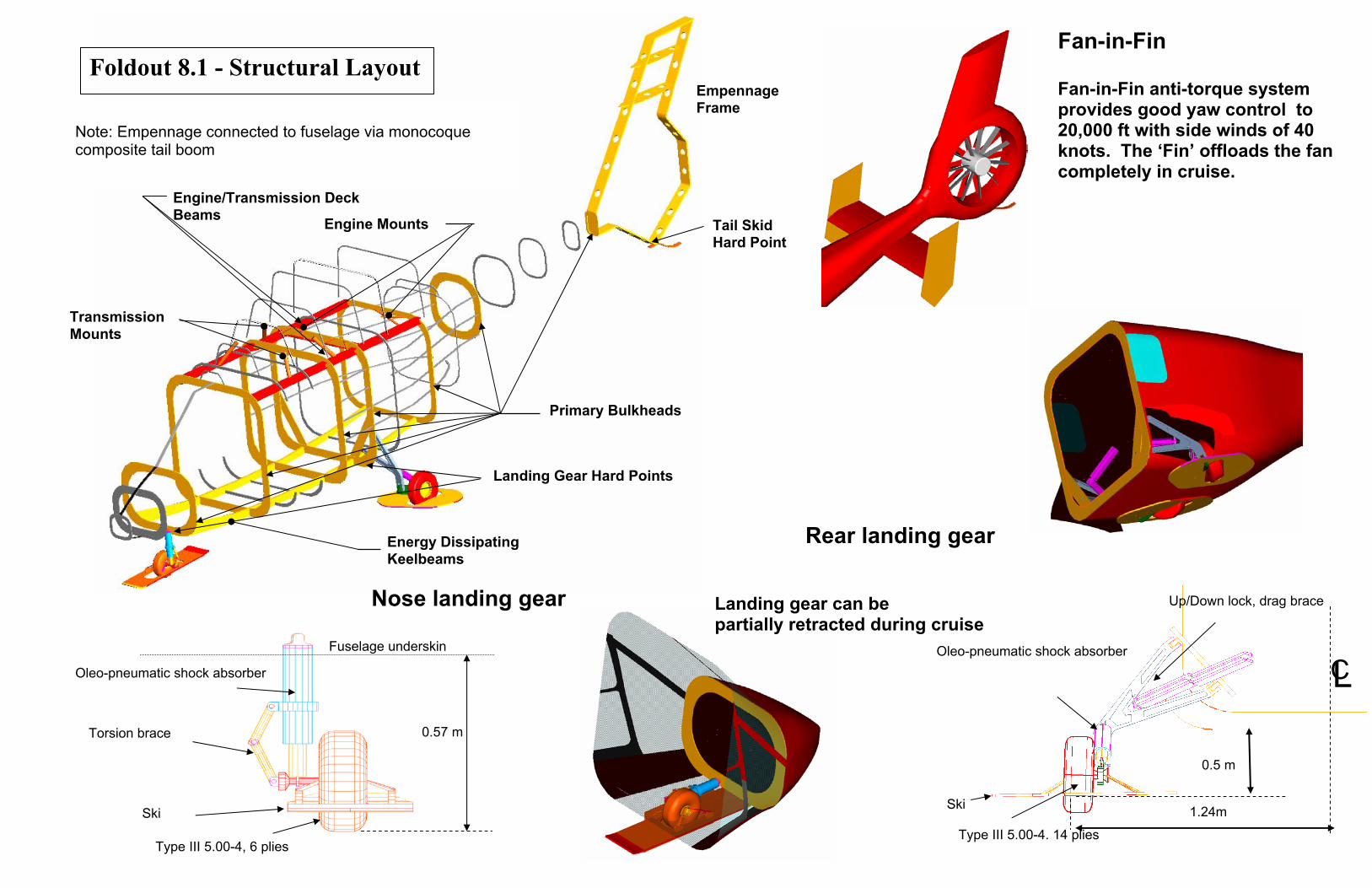
Tail Skid Hard Point
Primary Bulkheads
Landing Gear Hard Points
Transmission Mounts
Engine Mounts Engine/Transmission Deck Beams
Energy Dissipating Keelbeams
Empennage Frame
Note: Empennage connected to fuselage via monocoque composite tail boom
Nose landing gear
Fan-in-Fin Foldout 8.1 - Structural Layout
Fuselage underskin
Torsion brace
Ski
Oleo-pneumatic shock absorber
Type III 5.00-4, 6 plies
0.57 m
0.5 m
1.24m Ski
Type III 5.00-4. 14 plies
Oleo-pneumatic shock absorber
Up/Down lock, drag brace
CL
Fan-in-Fin anti-torque system provides good yaw control to 20,000 ft with side winds of 40 knots. The ‘Fin’ offloads the fan completely in cruise.
Landing gear can be partially retracted during cruise
Rear landing gear

UMD - Condor
56
8.1.2 - Crash Resistance
The mountain rescue mission of the Condor makes encounters with rough terrain and adverse
to protect its occupants
nts such as rollover or obstacle strike. Throughout the airframe, structural
members have been sized and arranged to maximize survivability by emphasizing energy
absorption keelbeams have been designed to absorb energy
by collapsing in a high buckling mode the amount of energy which is
absorbed during an emergency landing. The bulkheads and stringers are arranged to collapse
progressively when subjected to high inertial loads so that those loads are substantially reduced
before reaching passenger/crew accommodations like seats and litters. During blade-ground
ts, the primary danger to occupants is that the high bending moments and torsion
nsmitted to the rotor mast can cause the transmission to intrude into the cabin. The
transmission of the Condor is designed to prevent this type of movement through high strength
ceiling support. To allow for rapid exit from the helicopter, all doors have been designed to
remain operable after a high load event.
8.1.3 - Materials, Manufacturing, Construction
weather very probable. Therefore the airframe is rugged and designed
during high load eve
and dissipation. The webs of the two
; this pattern increases
strike even
tra
The bulkheads, stringers and keelbeams of the airframe are aluminum-lithium alloy. Lithium
being the lightest metallic element, it can reduce the weight of an alumin
for every 1% of lithium added. Most commercially available Al-Li alloys contain about 2%
lithium, offering a 7-10% reduction in density, and a 10-15% increase in elastic modulus. This
type of alloy also has good resistance to the growth o dvantageous for
rotorcraft airframes. These elements are also overlaid hite/epoxy skin. Graphite
fibers have superior strength and stiffness, but mage.
Kevlar is more resistant to impact damage, making
The engine/transmission deck is made f Titanium was selected over
ite sandwich construction for it resistance to heat and fire, as well
as oil corrosion.
odules of the Condor airframe are manufacture ly, and fitted with required
subsystems. Final assembly is made easier by the consistency of the cross section and simplicity
of interior structure.
um alloy by about 3%
f fatigue cracks, making it a
by a Kevlar/grap
the material is susceptible to impact da
it an ideal external skin.
rom titanium alloy plate.
aluminum-lithium and compos
The three m d separate

UMD - Condor 8.1.4 - Doors
The cockpit doors are large and hinged on the forward side. The hinge placement precludes the
possibility of the doors being blown open if improperly latched. Sliding doors are located on
both sides of the fuselage, and are wide enough to facilitate hoisting operations and litter
embarkation. All doors are braced to prevent jamming in the event of airframe warping, and can
be jettisoned in emergencies (14CFR29.783).
8.2 - Landing Gear Design
A trade study was completed to decide the configuration type for the Condor landing gear. The
options considered were the skid landing gear and the tricycle type retractable wheeled landing
gear. The prominent considerations are given in Table 8.1.
Table 8.1 - Landing Gear Configuration Comparison
Parameter Skid Configuration Retractable Wheeled Configuration Weight (% of MGW) 1.2 % 2.4 %
Flat Plate Area (% of total) 15 % 4 % Technical Complexity Simple Complex
Snow Operation Yes Needs ski attachment Adaptability Poor Good
Hoisting Hindrance Some interference No interference
Skid landing gears are usually preferred for use in light and middle weight category helicopters
because they are light and less mechanically complex to design than wheeled landing gears. They
also offer the ability to land and operate on snow, a necessary feature for mountain operations. A
wheeled landing gear provides ground maneuverability and has the advantage of being easily
adapted for multi-mission capability, a key feature considering the Condor is a high-powered
aircraft and could be valuable for a variety of missions. Another important criterion is the drag
enalty associated with each configuration. Skid landing gears offer larger flat plate area and
n Foldout 8.1, they have been designed to fit closely to the fuselage profile,
ducing parasitic drag. The skis were designed in accordance with 14CFR29.737 to withstand
145 knots), or alternately, 4 knots in cruise speed for the same cruise power
quired. The final factor in selecting the landing gear type was the interference of the gear with
p
greater drag than the wheeled configuration. The additional ski attachments required for snow
operation prevent the landing gears from being retracted completely into the fuselage. However,
as can be seen i
re
aerodynamic and inertial loads during flight. It is shown in Figure 8.1 that the power penalty
associated with a skid landing gear versus this retractable wheeled landing gear is approximately
30 kW (for cruise at
re
57

UMD - Condor
nder rescue operations by obstructing the litter’s hoisting operations. Skid landing gears could hi
hoisting path. A wheeled configuration, however, would be positioned beneath the fuselage and
would not cause any interference. Considering these factors, a retractable wheeled configuration
with attachable skis for snow landings was the landing gear arrangement chosen for the Condor.
1200Skid
50 100 150
200
400
1000
Fo light Speed (kts)
Req
u
Retractable
600
800
ired
Pow
er (k
W)
00
rward F
Figure 8.1 - Required Power xed and Retractable Landi ar
8.2.1 - Configuration
with Fi ng Ge
The position of the main and nose landing gears were decided to cater to the variations in the c.g.
experienced by the helicopter. For ground handling qualities, the recommended values for
landing gear static loads are 80% for the main landing gear and 20% for the nose landing gear
[Curr88]. The Condor has a wheel track of 2.2 m and a wheel base of 3.6 m. Under static
conditions, 77% of the load is carried by the main gears while 23 % is taken by the nose landing
gear. The lateral position of the rear landing gears was calculated to account for the rollover
angle requirements. A rollover angle of 57° was adopted for the design, a value well within the
recommended value [AMCP74].
Disc brakes are installed in the rear wheels to park the helicopter when grounded. The steering
control is implemented using a push pull system that incorporates a shimmy damper. The pilot
controls the helicopter using rudder pedals linked to the nose wheels. The maximum turning
angle of the wheel is 60° which allows for all required ground maneuvers.
58

UMD - Condor 8.2.2 - Tire Sizing
Tire pressures were kept low to allow operations on both prepared and semi-prepared runways.
The wheels of the main landing gear were designed for a maximum static load of 45% of MGW
(1,350 kg). The tires chosen were Type III 5.00-4 with 14 plies and a bottoming load capacity of
3,129 kg. The inflation pressure of the main landing gear wheels was 620.5 kPa (90 psi). The
nose wheel was sized for dynamic loads using a dynamic load factor of 2.5. For this wheel, a
Type III 5.00-4 with 6 plies was chosen. This wheel has a bottoming load of 1,450 kg and an
inflation pressure of 379 kPa (55 psi).
8.2.3 - Oleo Sizing
Single oleo-pneumatic shock absorbers were used for the main and nose landing gears. The
shock absorbers were designed to satisfy the drop test requirements of 14CFR29.723. Each gear
must be able to withstand a vertical drop height of .3 m (12 in) or a drop velocity of 2.5 m/s for
the reserve energy absorption drop test. Assuming a tire stroke 1/3 of the tire radius, shock
absorber and tire efficiencies of 0.85 and 0.47, respectively, a dynamic load factor of 3, and a
stroke margin of 0.013 m, the total stroke length of the oleo-pneumatic shock absorber was found
to be 0.114 m sorber as this
would enable the use of standard compressors to be used for servicing. The external diameter of
3 times the internal diameter and the length of the strut is typically 2.75
. An internal pressure of 12410 kPa (1800 psi) was chosen for the ab
the oleo is typically 1.
times the required stroke. The resulting dimensions of the oleo-pneumatic shock absorber are
0.27 m in length with an outer diameter of 0.05 m.
Section 9 - Details of Cockpit/Cabin Systems
9.1 - Crew Station Features
In addition to the instruments required for single pilot IFR flight, the Condor cockpit includes
several state-of-the-art systems. The Condor features programmable FMZ20001 Flight
Management System (FMS), which utilizes GPS as its primary navigation sensor, a Northrop
rumman LN-100G2, which represents one of the most advanced embedded GPS Inertial G
Navigation System (INS) available in the market, and a limited cabin crew hover control. To
assist in search operations, the Condor utilizes a retractable searchlight and Star SAFIRE II FLIR
camera, as well as Night Vision Goggle (NVG) compatibility. In addition, a hoist mounted video
camera provides the pilots with a view of the hoisting operations.
59

UMD - Condor
out9.2 - Cockpit Lay
9.2.1 - Cockpit and Cabin Access
Access to the cockpit is provided by two hinged doors on either side of the cockpit. Large sliding
doors are provided on both sides of the fuselage to facilitate cabin access and to provide sufficient
room for winching operations. The doors can be jettisoned in case of emergency.
9.2.2 - Pilot/Copilot Stations
The pilot station is located on the starboard side of the cockpit while the copilot seat is on the port
ide. Both pilot and copilot have full access to the full complement of flight instruments and
a state-of-the-art glass cockpit was selected for the baseline design, the
n system, hydraulic systems, auxiliary power
nit (APU), generator, and low fuel warning. These warnings are generated by the HUMS and
are displayed on th
s
controls. Although
Condor also offers an alternate less expensive avionics package. The details of this package are
presented later in this section.
The instrument panel (refer to Foldout 9.1) consists of five smart Multi-Function Displays
(MFDs), as well as standby attitude indicator, altimeter, airspeed indicator and vertical velocity
indicator. Also provided on the instrument panel are two backup radios, two analog clocks, two
radar altitude gages, a compass, and two master caution light panels. The radios can be operated
using a keyboard on the control display units (CDUs) or via the backup radio display/dials. An
analog backup clock is used in preference to a digital clock, to provide a visual feel for the time
elapsed. The caution lights installed on the instrument panel provide visual indications of
failure(s) in the engine and/or drive train lubricatio
u
e MFDs.
The overhead console (refer to Foldout 9.1) houses the aircraft system controls which include
circuit breakers, engine controls, pilot heat switches, anti-ice system controls, and two radio/Inter-
Communication Select (ICS) panels. The center console contains two CDUs, console light
controls, external light controls, crew hover control selector, and main hoist control panel. The
CDUs provide the interface with the FMS, and can also display weather related data and can
work with Enhanced Ground Proximity Warning System (EGPWS) software, to provide a
graphical display of origin or destination terrain information, the terrain data provides crew
awareness of landing or take-off location.
60

Foldout 9.1 - Cockpit Layout
Note: Not to scale, does not represent actual equipment.
Overhead Console
Circuit Breakers
De-ice/Anti Ice/ Pitot Heat
Analog Clock
Engine Controls
Radio/ICOM
Radio Volume Control
Master Caution Light Barometric Altimeter
Airspeed Indicator
Compass
FLIR / Video Display Multi Function Displays
Attitude Indicator
Keyboard Display and Input
Light, Vent/Heat, Hoist Power
Vertical Speed Indicator
Instrument Panel
Center Console
#2#1
#3
Radar Altimeter
Radio
Vertical Speed Indicator
Barometric Altimeter
Analog Clock
Instrument Panel (Alternate Configuration)
Airspeed Indicator Compass
FLIR / Video Display
Master Caution Light
Attitude Indicator
VOR OBS Engine RPM
Engine and Fuel Gauges
Radio
Heading Indicator
Turn Coordinator
Multi Function Displays
#4 #5

UMD - Condor
62
The collective stick has controls to turn the searchlight and FLIR on and off, to control the
direction of the searchlight/FLIR, and to operate the searchlight retraction mechanism. The
cyclic stick is equipped with the hoist release/cable shear switch (shielded switch to avoid
accidental release), hoist fixed speed control roller, stick trim button, trim release button, moding
cursor control (coolie hat), and ICS call trigger.
9.3 - Cockpit Systems
9.3.1 - Sensor Suite
The Condor is equipped with LN-100G embedded GPS inertial system, which provides inertial,
GPS, and hybrid navig ines the Zero-lock Laser Gyroscope with the latest
electronics, and GPS to provide enhanced position, velocity, and heading reference. The output is
available in digital form which is fed directly to MFDs. The INS/GPS unit provides true heading,
pitch, roll, position, velocities and accelerations which are also sent as an input to the FMS
unit is located near the c.g. to provide accurate measurements. The accuracy of the GPS receiver
can be improved by providing differential corrections from a Differential GPS (DGPS) reference
station located nearby.
ation solutions. It comb
. The
9.3.2 - Multi-function Displays
The Condor’s instrument panel has a total of five Northrop Grumman Colorsmart MFDs. All the
interchange figurable for changing roles and missions.
Two MFDs are provided on the pilot’s side and tw pilot’s side. In ad
central MFD is provided for the FLIR display during the flight. During rescue, this will be used
as a video display for the pilot to monitor the hoisting operation.
Based on open system architecture, each MFD has a separate processor which allows it to
communicate independently with the data bus rather than through a main mission computer. The
advantage of such a system is that an individual chip failure would only affect a single MFD, and
will not compromise the mission capability. The increased redundancy of this type of system
outweighs the increased cost incurred by having a separate processor for each display [Nort04b].
The main pages of the MFDs include the Primary Flight Displays (PFDs include attitude
indicator, indicator, vert metric p inator
gation pages, fuel and engine related information, sensor p R page, system
status page, and the Warning/Caution/Advisory (WCA) page. The interchangeability and
MFDs are identical, able, and fully recon
o on the co dition, a fifth
airspeed ical velocity indicator, baro ressure, turn coord
ages, FLI
etc.), navi

UMD - Condor
63
configurability of the displays makes it possible to have a wide range of information displayed in
the cockpit panel.
9.3.3 - Communication Systems
The communication systems of the Condor include cockpit-to-cockpit, cockpit-to-cabin, cockpit-
to-rescuer and over the horizon channels to aid in the rescue operations. The equipment provided
includes VHF-FM ground and airborne radios, a VHF-AM radio, a UHF-AM radio and a high
frequency radio for non-line-of-sight communications. An intercom system is provided to
facilitate hands off communication with the aft crew. Throat microphone and earpiece are
provided to the rescuer involved in ground operation to communicate with the crew. Chemlights
are also provided in case of a communication system failure and/or to minimize voice traffic
being relayed to the helicopter crew.
9.3.4 - Mission Systems Equipment
The mission system equipment includes NVG filters and dimmers, Primus 700 SAR/Weather
RADAR system, a Star SAFIRE II FLIR camera, a data loader, a retractable SX-5 Starburst
Searchlight, and IFR equipment (Stability Augmentation Systems (SASs), Attitude Retention
Systems (ATTs), Autopilot Systems (APs), Flight Director Systems (FDs); see Section 11). FLIR, Searchlights, and Radar System
The NVGs, FLIR, searchlights, and weather radar can be
combined together to enhance search and rescue at night. Star
SAFIRE II [Flir01] provides enhanced thermal sensitivity and
powerful optics for superior range performance. A SX-5
Starburst Searchlight [Spec01] is located in the nose of the
helicopter alongside the FLIR system. It is equipped with a
500W short arc Xenon lamp which delivers a minimum of 15
million candle power. The searchlight is retractable to minimize
parasite drag when not in use. The Condor is equipped with a
Primus 701A SAR/Beacon/Weather radar system that is
integrated with color weather radar and personal beacon detection. With high resolution
precision surface mapping, minimum detection range as low as 450 ft and Doppler turbulence
detection, Primus 701A is tailor-made for the operations in mountainous environments, where
sudden exposure to turbulence can be hazardous. The Primus701A can also be used to locate and
Figure 9.1 - FLIR

UMD - Condor
04c].
nhanced Ground Proximity Warning System
oneywell Mark XXII - Enhanced Ground Proximity Warning
terrain and other aircraft [Hone04d].
identify personal locator beacons, a commonly used safety tool for today’s mountain
climber/hiker [Hone
E
The Condor is equipped with a H
System (EGPWS). EGPWS provides a real-time situational awareness display of surrounding
terrain and obstacles in relation to an aircraft's altitude and flight path. The system is designed to
visually and audibly alert the flight crew of potential terrain/obstacle conflict. It includes a high-
resolution built-in terrain database designed to help eliminate controlled-flight-into-terrain (CFIT)
type accidents [Hone04b]. A Traffic Alert & Collision Avoidance System (TCAS) (Honeywell
CAS-100 4MCU) is included as well, to increase traffic and terrain awareness of the crew. The
TCAS system interacts with the EGPWS system to retrieve terrain data and provide traffic
solutions that optimize separation from
9.3.5 - Flight Management System
The flight management system uses the position information obtained from the GPS/INS system
and combines with the information from its internal database to guide the helicopter along the
optimized flight path for the specific mission. The Honeywell FMZ-2000 Flight Management
System provides this feature on the Condor. With Honeywell’s SmartPerf (Smart Performance)
rmance characteristics of a specific aircraft and provides
Hone04a]. A data
software option, the FMS learns the perfo
the crew access to numerous performance calculations. Using it
with atmospheric data, SmartPerf provides pilots with the followin
(i) Time, fuel and predicted altitude at all waypoints.
(ii) Time and distance to step climb.
(iii) Predictions for stored or active flight plans.
(iv) Equal Time Point.
(v) Point of no return.
(vi) One engine performance data.
SmartPerf logic originates with the baseline performance informat
fine-tunes to the performance characteristics of the aircraft when installed [
loader is used to help reduce the mission start times. If the exact location of the target is available
then the related information can be directly downloaded from a disk carried with the crew from
their point of origin, or can be updated via uplinks from a data-stream whilst en route to the
rescue area. From this information, the FMS can propose the optimized flight path.
s performance database along
g performance calculations:
ion fo ft and r the type of aircra
64

UMD - Condor 9.3.6 - Alternate Avionics Package
The design team is aware of the fact that the current design faces a very competitive, cost-
made to keep the cost to a minimum without conscious market, and every effort has been
compromising the mission capability. For this reason, the Condor can be equipped with an
alternate, less expensive avionics package that has two MFDs, with primary flight information
being provided using mechanical gages. In addition, the INS/GPS system would be replaced by a
less costly unit, and if the mission does not require operation in mountainous regions, the
EGPWS may not be required. To facilitate this, the elements of the avionics package are installed
in accessible areas and can be removed or replaced easily to fit the client’s needs.
9.4 - Cabin Systems
The hoist control panel is located to the right of the starboard cabin door. It contains control for
e hoist power and motion. It also has a cable fault sensor light and a cable position indicator. A
so available near the crew station, which can be used to
th
tethered portable hoist control is al
perform the hoisting operation while leaning out of the cabin door, a safety belt provides a secure
harness to the crew member manning the hoist.
9.5 - Cabin Equipment Layout
The cabin of the Condor is arranged to maximize the amount of usable working space for the
crew. The SAR mission provides the cabin crew two priorities: loading passengers, and caring
for patients. Loading an immobile patient into the helicopter requires maneuvering the rescue
li ack, as shown in Foldout 9.2. When the
h l crew member can help to fit the rescue litter through the
d rescue litter must be brought through the door
w hoist and moved into position.
T cabin, the two litters in the supine position are stacked
eiling. The
tter through the sliding door and onto the appropriate r
elicopter is on the ground, an externa
oor. During hoisting operations, however, the
hile suspended from the
o maximize working space in the
vertically on the port side of the cabin. This allows adequate room for the crew to maneuver the
rescue litter into the desired position and to provide medical attention to the patients once they are
loaded. The first litter is 160 mm (6.3 in) above the cabin floor, allowing accessibility to the
patient for a seated crew member. The second is 640 mm (25.2 in) above the first, locating the
patient at about waist height, and providing accessibility to a standing crew member. This layout
provides an additional height of 640 mm (25.2 in) above the top litter to the cabin c
65
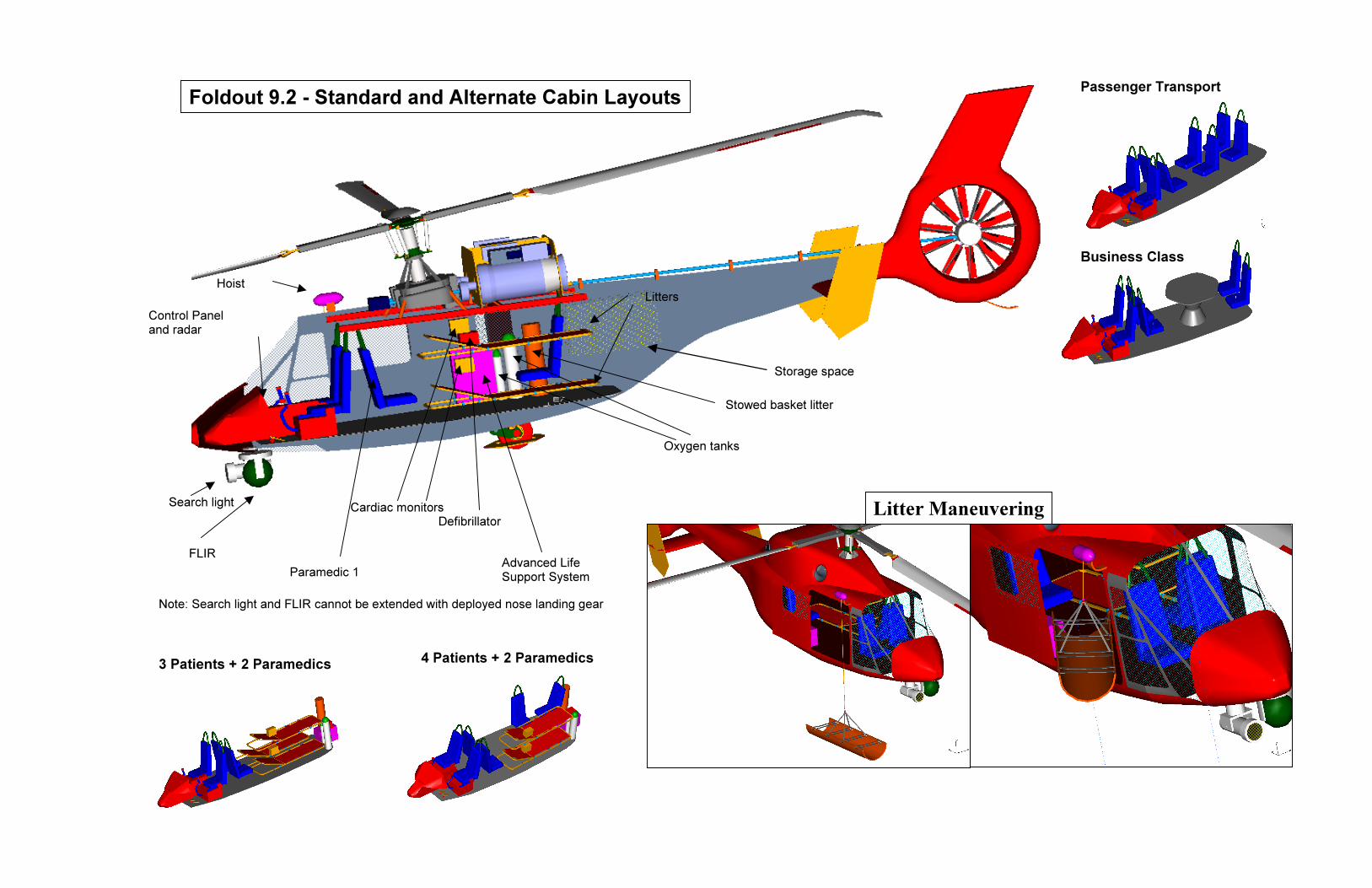
Litte
FLIR
Search light
Control Panel and radar
Storage space
Paramedic 1
Hoist
Advanced Life Support System
Cardiac monitors
Oxygen tanks
Defibrillator
Stowed basket litter
Note: Search light and FLIR cannot be extended with deployed nose landing gear
Litters
Passenger Transport
3 Patients + 2 Paramedics 4 Patients + 2 Paramedics
Business Class
Foldout 9.2 - Standard and Alternate Cabin Layouts
Litter Maneuvering

UMD - Condor
67
height of
patient to come down unassisted, if he/she is mobile. The starboard side of the cabin is open,
leaving room for the crew to move. Inertial reels allow the crew members to move about the
cabin while maintaining a secure tether to their seats. The crew seats are arranged at the head and
side of the litter bay, so that one paramedic is positioned for patient airway management while the
other can assist with other tasks. The medical equipment is stowed against the walls of the cabin,
with the monitor/defibrillator units close to the chests of the patients. Rescue equipment and the
large oxygen cylinder are located in the aft storage space, which also holds modular avionics bays
(standard and alternate cabin layouts can be seen in Foldout 9.2). There is an access hatch into
these bays for easy m intenance, installation, and replacement of avionics.
Section 10 - Mission Equipment
the top litter is low enough to allow the crew to easily load a patient onto it, and for the
a
The specified mission task of the Condor, in addition to the flight profile, requires two distinct in-
flight operations. The first is a hoisting rescue of stranded victims from a hazardous
environment. The second is the application of life-saving medical aid for the rescued victims
during the return from the rescue site. Both operations are indeed critical, and so a considerable
research effort was made to ensure that the Condor was outfitted with state-of-the-art search and
rescue and medical equipment for a high rate of mission success.
10.1 - Rescue Gear
10.1.1 - Retrieval Gear
The Con equipped with rescue equipment that
enables it to retrieve va ations of
ambulato ®
Rescue System is a highly compact rescue stretcher
which allows horizontal or vertical hoisting. Although
it provid trapped in,
it can be rolled up and packed away when not in use.
Patients who do not need to be supine during hoisting
can be retrieved with either the rescue basket, which has
a loading capacity of 272 kg, or with the rescue seat.
The rescue seat can lift or lower two people at a time, and is
used by the United States Army.
dor is
rious combin
ry and immobile patients. The Sked Basic
es rigid support when a patient is s
Figure 10.1 - Rescue Litter[Sked04]an update of the forest penetrators

UMD - Condor
10.1.2 - Hoist
The Condor’s external hoist is a model 42325 from Goodrich Hoist and
Figure 10.3 - Rescue Basket [Life04]
Figure 10.2 - Two-person Rescue Seat [Life04]
Winch Company. An
lectric version was chosen for ease of installation, maintenance characteristics, and reliability.
Goodrich hoists feature tra unlimited angle between
ing, so that
terrupted rescue operations can be resumed. This is not possible when
e hoist housing.
e
nslating drum technology, which permits an
the helicopter and the load to be lifted. This is an essential feature in uneven terrain or in the
presence of obstacles, both of which are known to be factors in mountain rescue operations. The
hoist has a 272 kg lifting capacity, a cable length of up to 88.4 m, and a
hoisting speed of 38 m/min. An accessory cable cutter is mounted in the
cabin behind the pilot seat. This device is an improvement on the included
internal cutter, because it allows the cable to be spliced after cutt
Figure 10.4 - External Hoist
[Good04]
in
the cable is cut inside th
10.1.3 - Additional Rescue Equipment
During rescue operations, it is essential that the pilots an
payload. Accordingly, the Condor is equipped with a v
gives a continuous, real-time view of the rescue operation
10.2 - Medical Equipment
The Condor is well-equipped to handle medical emergencies. The cabin floor is an integral
that is leak-proof, protecting the underlying structure a
Supine patients are strapped into stretchers which are in
normal or most high-load conditions, as required by 14CFR
head to recline at a range of angles, facilitating the paramedic’s access to the airway. There are
two litters for supine patients, ea
d crew have good views of the hoisted
ideo camera and a full-color display that
.
unit
nd fuel tanks from any medical effluvia.
stalle under
29.785. The litters allow the patient’s
ch of which is locked into a rack cantilevered by two of the
fuselage structure’s primary bulkheads.
d so that they do not shift
68

UMD - Condor
edical equipment is located in close proxim
an not be immediately
blanket, signaling devices such as a m al
cator beacon, a light and flares, potable water, water purification tablets, and hi ood
be left for treatment of an injured patient.
Weight has been considered in the selection of the medical equipment for the Condor (see Table
10.1), but quality and utility were the primary drivers. Every item is state-of-the-art for helicopter
EMS, and enables the crew to provide quality care to the patients.
Rescue Item kg Medical Item kg
ity to the chests of the patients. This
Figure 10.6 - CCT Monitor, Pacemaker, & Defibrillator
Figure 10.5 - AED [Card04]
[Zoll04]
The primary m
includes two of the Zoll CCT combination cardiac monitor, defibrillator, and pacemaker. These
devices feature full color displays and hospital quality monitoring. A battery-operated automatic
external defibrillator (AED) is available for additional patients, or can be deployed outside the
helicopter. Two advanced life support kits are stowed in cabinets on the starboard side of the
cabin. These kits contain various airway, diagnostic and trauma supplies. The cabin is fitted with
conveniently placed hooks for intravenous bags and tubes. There is a distr
oxygen; an E-size oxygen cylinder is located next to the forward facing para
M90 oxygen cylinder is racked in the aft stowage space.
Emergency packs are carried on board the Condor in case any person c
transported. These packs contain a space
ibution system for
medic and a larger
irror and person
gh-energy flo
rations. First-aid kits are included, and the AED can
Rescue equipment is stored aft of the main cabin, where it is readily accessible to the crew.
Table 10.1 - Rescue and Medical Equipment Weights
Basket Litter 8.6 Advanced Life Support (x2) 22.7 Rescue Basket 18 Monitor Defibrillator (x2) 16.8 External Hoist 45 Portable AED 3.1 Rescue Seat 8.1 Stretcher System (x2) 17
69

UMD - Condor
Section 11 - Flight Control System ing trailing edge flaps on the rotor blades to
fan-in-fin uses conventional controls.
optimize performance and handlin
e (FBW) system was selected for the design.
r and fan-in-fin blades are generated b
(PFCS), and the Automatic Flight Control
Network Hardware Processor is provided to
Flight d by us
roduce clic pitch. The The
light ndor was designed to g
ualitie by-wir
ignals the main roto y the
o su ystem
ystem
ere change in the software), improved
ult tolerance and ease of incorporating onboard fault diagnostic systems. The digital FBW
control in the Condor is achieve
the required collective and cy
Control System (FCS) for the Co
s. A triple redundant, digital fly-
to the actuators and servos of
bsystems: the Primary Flight Control S
(AFCS). Another subsystem, a Neural
p
F
q
S
tw
S
perform onboard fault diagnosis for the rotor flaps. The dual, self-checking, triple redundant
PFCS electronically connects the pilot’s control inputs to the actuators and servos for safe
operation of the aircraft, and is a digital equivalent of the traditional mechanical linkages. The
AFCS provides command shaping, control mixing, a suit of holds, and the necessary level of
stability and control augmentation required for reliable mission performance.
The FBW system, which represents the state-of-the-art in FCS, was selected in place of a
mechanical system it presents potentials for weight savings, enhanced handling qualities,
flexibility to accommodate changes (which requires a m
fa
control system has automatic maneuver envelope protection, as the flight computer rejects
maneuvers outside the operational flight envelope.
11.1 - Design of FCS
11.1.1 - Details of Flight Control System
The FCS architecture f the Condor’s flight
ntrol system is the tr Co l FCCs), which provide flight control law
rocessing and also p nd C ubo01]. The design
rovides dual CPUs f , nn maintain the control
apability in worst case scenarios of f re FCCs. There are four types of
ight control laws for the Condor FCS: RD (Rate Damping), RCAH (Rate Command Attitude
(SAS) that provides damping
for the Condor is shown in Figure 11.1. The core o
co iplex Flight ntro Computers (
erform redu ancy management for the F S [K
or each FCC and an analog backup cha el to
ailu or malfunction of all
p
p
c
fl
Hold), ACAH (Attitude Command Attitude Hold), and TRC (Translational Rate Command). In
addition, turn coordination and side slip suppression can be provided to reduce pilot workload
[Satt01]. The rate damping mode is a stability augmentation system
70

UMD - Condor
71
to any unwanted oscillation detected by the rate sensors. The other three modes are stability and
control augmentation systems, which have been designed to reduce the cross-coupling between
control axes. The RCAH allows the pilot to establish a constant angular velocity (rate command)
in response to a constant displacement of the control stick. The rate mode is designed to realize
quick response under visual meteorological conditions. The ACAH allows the pilot to establish a
hands-off stabilized attitude proportional to the stick displacement. The attitude mode has
sufficient stability required for the instrument meteorological condition. TRC provides the
control necessary for difficult flight tasks, such as precision hover at a point to perform hoisting
operation.
Model
PILOT
Control Input
Stick Back- drive
Stick Controllers
FCC - Control Laws
RDPFCS
AFC ACAH
RCAH
TRC
NNHP FDM
ACC
C
Fault Reporting
Actuator / Rotor
Helicopter Dynamics
SENSORS - Helicopter state GPS/
DGPS - Position
Flight Director
Autopilot
Guidance Function
Flight Plan Selection
Flight Management
Way-Point
Autopilot Commands
Primary Flight Display
Figure 11.1 - FCS Architecture for Condor
Autopilot
C = Comparator ACC = Actuator Control Computer RD = Rate Damping NNHP = Neural Network Hardware Processor FDM = Fault Diagnostic Module RD = Rate Damping TRC = Translational Rate Command FCC = Flight Control Computer

UMD - Condor
s
F
n
m
The Actuator Control Computers (ACCs) drive the actuators to deflect the embedded trailing
edge flaps and to drive the fan-in-fin servos in accordance with the actuator position command
from the FCCs. When a failure of all the FCCs is detected, ACC automatically switches the
control to an analog backup channel to maintain the minimum control capabilit
Automatic flight and Flight Director flight in Condor is accomplished by coupling FMS with
CC, as shown in Figure 11.1. The autopil g function and the guidance function is
provided for the purpose. The autopilot coupling function provides automatic guidance and
control, according to the autopilot commands calculated in the Flight Management Computer
(FMC), to follow defined in lan. The guidance function judges the
condition of the helicopter from state flags and waypoint data, and determines the command gain
ec for calculating the guidance com he guidance command is generated by
ultiplying the error calculated from the preset courses by command gain. T mode
being the most stable mode is used for automatic flight and FD flight [Kubo01]. The flight
director system provides pre-programmed paths and furnishes the steering commands necessary
to obtain and hold a desired path to preprogra estinations. The pilot c out of
preprogrammed destinations using the keyboard of the control display unit.
11.1.2 - Neural Network Based Fault Detection
The current design proposes to use Neural Netw hich offers an
efficient and cost-effective method to install fault s, permitting on-
board diagnostic modeling of very complex subsys eural network
hardware processor is used to monitor the performance of trailing edge flaps, the normal
functioning of which is critical for mission success. The n ork hard e
functions of subsystem modeling to support the fault diagnostics, and aircraft parameter modeling
that is used in the controller algorithm to optimize the control input. The neural network models
y [Kubo01].
ot couplin
the flight path the flight p
essary mand. T
he attitude
mmed d an select
ork hardware processors, w
diagnostics in flight system
tems. In the current design, n
eural netw ware performs th
the normal operation and failure modes of the flaps, and can predict their failure. This requires
training which involves the collection of data that characterize normal and failure modes of
operation of the trailing edge flaps. This data can be generated either using a simulation or from
test operation of the system [Urne96]. The information regarding possibility of a failure would be
displayed on the MFDs, which gives pilot ample time to take corrective measures.
72

UMD - Condor
73
11.2 - Stability and Control Analysis
A simplified linear model was developed based on the methods of Padfield & Prouty [Padf96],
[Prou86], to carry out stability and control analysis. Stability and control derivatives were
estimated from first principles, and using simplifying assumptions for the aerodynamic
characteristics of the fuselage. The stability and control derivatives for two flight conditions
(hover and forward flight at 145 knots) are given in Table 11.1. The force derivatives and the
moment derivatives are normalized by the design gross weight and the moment of inertia
respectively. The pitch damping, Mq and the roll damping, Lp, are important derivatives, because
of their close relationship to the short-term and moderate amplitude response, which influences
the handling qualities of a helicopter. Larger magnitudes of these derivatives indicate a stable
helicopter. Table 11.1 suggests that Condor has good roll and pitch damping. This is because of
the use of a bearingless hub, which gives us greater effective hinge offset than articulated rotor.
11.2.1 - Lateral & Longitudinal Modes
Figure 11.2 shows the estimated longitudinal and lateral poles for two different flight conditions,
hover and cruise at 145 knots. Like any other helicopter, the phugoid mode of Condor is unstable
in hover, however the stability increases with forward speed so the instability is not critical.
During hover, the pitch and heave modes are uncoupled since the Mw derivative is zero. In
forward flight they are coupled and form a short period mode which is stable. Due to significant
high damping, the roll subsidence is the most stable mode.
Figure 11.2 - Longitudinal and Lateral Flight Stability Poles
a) Hover b) Cruise 145 knots

UMD - Condor
ode is neutrally stable in hover and becomes more As seen from Figure 11.2 the dutch roll m
stable with forward speed. Dutch roll is highly dependent on the coupling of roll and yaw, where
the dihedral effect (Lv) and yaw due-to roll rate (Np) are the main contributors. Again, because of
the bearingless design both of these derivatives are found to be large and negative in cruise. A
negative value of Np tends to destabilize the Dutch roll oscillation, however, the strong dihedral
derivative is sufficient to stabilize this mode.
11.2.2 - Tail Sizing
The size of the horizontal stabilizer is decided by two conflicting requirements, the stability of the
phugoid mode and the stability of speed modes. The phugoid mode becomes unstable with
increased horizontal stabilizer size, while decreasing the stabilizer size makes the speed mode
unstable. A balance was achieved by selecting a horizontal stabilizer size of 1.4 m2 (15 ft2),
which gave adequate stability to both the modes.
11.3 - Handling Qualities
The ADS-33 (Aeronautical Design Standard - Performance Specification) establishes the criteria
for acceptable handling qualities for rotorcraft. These requirements are based on open-loop Bode
plots in roll, pitch, and yaw. The bandwidth and phase delay are calculated from these Bode plots
to determine the handling quality levels. An aircraft with high bandwidth and small phase delay
would have a quick, crisp response, which is preferred by the pilots. The handling quality of the
bare airframe with AFCS off and on needs to be investigated [Celi04]. A preliminary analysis
was performed on the frequency response between the pitch attitude and longitudinal cyclic
control of the bare airframe for small amplitude changes in attitude at a cruise speed of 145 knots.
The short term response was observed to have a bandwidth of 1.4 rad/sec and a phase delay of
0.03 sec, which implies a Level 2 handling quality. The use of a flight control system with
RCAH, ACAH, and RD (available with Condor AFCS) would decrease the pilot workload and
improve the handling qualities.
74

UMD - Condor
Derivative Hover Cruise Units Derivative Hover Cruise Units Xu -1.01 -0.48 1/sec Lu 0.03 0.03 rad/sec-ft
Xv -0.05 0 1/sec Lv -0.07 -0.68 rad/sec-ft
Xw 0 -0.18 1/sec Lw 0 -0.11 rad/sec-ft
Xp -5.44 -2.88 ft/rad-sec Lp -9.2 -8.97 1/sec
Xq 13.65 21.03 ft/rad-sec Lq -3.66 -1.9 1/sec
Yu 0.04 0.2 1/sec Lr 0 0.1 rad/sec-ft
Yv -1.02 -0.63 1/sec Mu 0.27 0.07 rad/sec-ft
Yw 0 -0.16 1/sec Mv 0.01 0 rad/sec-ft
Yp -13.65 -19.36 ft/rad-sec Mw 0 -0.21 1/sec
Yq -5.44 -2.56 ft/rad-sec Mp 1.45 0.83 1/sec
Yr 0 -242.5 ft/rad-sec Mq -3.66 -4.51 1/sec
Zu 0 0.02 1/sec Nu 0 -0.12 rad/sec-ft
Zw -0.32 -0.64 1/sec Nv 0 0.02 rad/sec-ft
Zp 0 0.41 ft/rad-sec Nw -0.44 0.07 1/sec
Zq 0 243.2 ft/rad-sec Np 0 -0.3 1/sec
Zr 0 -7.96 ft/rad-sec Nr 1.74 -0.92 1/sec
Derivative
0Xθ
1CXθ
1SXθ
0Yθ
1CYθ
1SYθ
0Zθ
Table 11.2 - Control Derivatives in Hover and Forward Flight
Hover C
-3.56 -
-36.29 -
239.9
0
-239.9 1
36.29
-176.2 -
Table 11.1 - Stability Derivatives
75
ruise Units Derivative Hover Cruise Units
144.6 ft/sec2-rad 0
Lθ 0 0 1/sec2
22.28 ft/sec2-rad 1C
Lθ -121.2 108.52 1/sec2
154.5 ft/sec2-rad 1S
Lθ 24.45 16.53 1/sec2
-0.14 ft/sec2-rad 0
Mθ -5.87 34.18 1/sec2
49.06 ft/sec2-rad 1C
Mθ 9.73 6.45 1/sec2
22.71 ft/sec2-rad 1S
Mθ -64.34 -44.9 1/sec2
320.8 ft/sec2-rad 0
Nθ 11.09 10.66 1/sec2

UMD - Condor
Section 12 - Mechanical Subsystems (Engine/Transmission) 2.1 - Engines1
The gin ection 4.5) is the civil ve the
RAH-66 manch ecif e CTS800-0 is basic l, w he N
includes an optional nose gearbox which reduces the RPM from 23000 to 6402. The engine has
an envelope diamet .55 .7 thout the optional nose gearbox, is 0. 33.7
in) long he CTS-800-4N has a pressure ratio of 14 and weig 5 kg lb). Full
Authorit igital El ic C l (FA system provides automatic s g c he
engines. If taking off from an area with ground support, the engines can instead start using a
tempora bilical power connection which saves their battery p The lect he
main gearbox drives a power takeoff gear that provides er to a generator (see Section 12.2.7).
An APU provides pneumatic o es.
12.1.1 - Engine Structural Integration
CTS800 en e (see S rsion of the T800 engine that was to power
Co e. Sp ically, th the mode hile t CTS800-4
er of 0 m (21 in) and wi 86 m (
. T hs 18 (408 The
y D ectron ontro DEC) tartin ontrol of t
ry um ower. col or gear in t
pow
starting f the engin
insta side by s epar y a
ain .
Two CTS800-4N engines are lled ide, s ated b
distance of 0.76 m (30 in), and located behind the m gearbox
he tail rotor drive shaft is routed between the engines. In
ccordance with 14CFR29.903, firewalls are installed to isolate the
ngines from ea
mounted using two A-frame supports in nt an re
Elastomer shock l w A-frame support is
connected to the engine to isolate the engine from excess vibrations.
The optional original equipment manufacturer (OEM) nose
gearboxes which supply a reduction of 3.5926 were used. Using these
gearbox ce ification osts w nd development cos
connect the output shaft of the OEM gearboxes to clutches m unted
Table 12.1 tings for CTS-800-
Power kW (shp)
T
a
e ch other and from other systems. Each engine is
the fro d one in the ar.
mounts ocated here the
rt c and lo ers research a
o at the
- Power Ra 4N
Max Continuous 955 (1281) Takeoff 1014 (1361)
Continuous OEI 1014 (1361) 2 Min OEI 1108 (1487) 30 second OEI 1208 (1621)
76
CTS8 4N Figure 12.1: LHTEC
00-
reduction stages reduces
ts. Flexible couplings
inp he g . ut of t earbox

UMD - Condor 12.1.2 - Engine Performance
The CTS800-4N power ratings for each engine are shown in Table 12.1. The loss in power for
both engines with altitude is plotted in Figure 12.2. Total installation power losses are assumed to
be 5% of the total maximum continuous power.
Figure 12.2 - Power Variation With Altitude
12.1.3 - Engine Subsystems
The oil tank capacity of the CTS800-4N is 3.2 liters (0.83 gal). In
integrated into each engine. These oil systems also lubricate the
eliminating the need for a dedicated lubrication system which would
4N is manufactured with an inlet particle separator and therefore m
14CFR29.1091 regarding foreign object ingestion without the use o
protection system. The Full Authority Digital Engine Control System
flight control system to ensure optimal engine performance. In addition, condition and usage
information is relayed to the cockpit multifunction display and is recorded by the HUMS.
dependent oil systems are
OEM reduction gearbox,
add weight. The CTS800-
eets the requirements of
f a et
communicates with the
2.2 - Transmission Design
separate aircraft inl
1
12.2.1 - Design Baselines
Because of the OEI req altitude ain rotor transmission must
transmit a proportionally t of power than transmissions in helicopters of a
comparable gross weight. Taking this design specification into account, care was taken to
minimize gearbox weight mizing compactness. Once a basic design was selected,
consideration was given to licity, ease of a assembly, noise minimization,
uirement for high hover, the m
larger amoun
while maxi
overall simp ssembly/dis
77

UMD - Condor
ssues. Table 12.2 lists the baseline parameters the transmission is
Parameters
fatigue, and manufacturability i
required to satisfy.
Table 12.2 - Design Baselines [Heat93]
Design Baseline Engine Shaft Speed: 23,000 RPM (LHTEC03) Main Rotor Desired RPM: 332 RPM HP to Main Rotor (each path): 680 kW (912 hp)
Allowable Stresses Max Hertz Compressive Stress: 1,310 MPa (190,000 psi) Bending Stress: 413.6 MPa (60,000 psi)
12.2.2 - Configuration Study
Standard Gearbox Configuration
The first option considered for the transmission design (shown in Figure 12.3) is representative of
a more standard gearbox configuration. This concept contains a spiral bevel stage, a collector
gear stage, and a planetary stage. This design, similar to the AH-64 Apache’s ain gearbox, is
considered to be a proven design, but the additional reduction stage and absence of torque-
litting results in a larger weight for the desired power rating. The configuration chosen for the
split-torque design utilizing face gears and a collector gear. This
m
sp
gearbox of the Condor was a
design is preferable over the standard design in many ways. The split-torque design lowers
individual gear weight and size resulting in a more compact layout. The combination of face
gears and collector gear provides the necessary reduction in as few stages as possible. Using
fewer stages and components results in lower probability of failure, lower overall noise, easier
and cheaper maintenance, and is easier for the HUM system to monitor (see Section 12.3). The
chosen design also allows for weight savings in terms of necessary bearings and oil.
Figure 12.3 - Standard Gearbox Design
78

UMD - Condor
as sized to be capable of operation in all possible flight regimes of the
mission profile. To hover w (12,000 ft), the helicopter
requires 680 kW (912 hp) of powe e that results in the highest torque
loading, t as designed to accommodate.
In an em ate safely close to 800 kW (1073 hp)
for approximately 2 minutes. After olving torques higher than the rated
maximum, the drive system must undergo a complete inspection to approve the helicopter for
rther flight time. The necessity of right-angle nose gearbox assemblies was averted because the
opter allowed the engines to be located directly behind the main
te to utilize the OEM provided gearboxes for the first state of
Stage 1 Stage 2 Stage 3
Split-Torque Gearbox Configuration
The main gearbox w
ith one engine inoperative at 3,658 m
r. Because this is the cas
his is the power rating each torque path in the gearbox w
ergency situation, the gearbox will be able to oper
any scenario inv
fu
weight distribution of the helic
gearbox. It was deemed appropria
reduction. This stage brings the engine output shaft speed of 23,000 RPM down to 6,402 RPM
before entering the gearbox. The output shafts from both OEM gearboxes are parallel to each
other and to the transmission deck structure. Flexible couplings at this point allow for some shaft
misalignment and structural flexing. Lucas Aerospace flexible couplings were chosen due to
their single piece design that is light weight, highly reliable, and easy to maintain. Spring-type
overrunning clutches are located at the point of gearbox entry to allow for shaft disengagement.
Each input shaft of the gearbox drives a 21-tooth spur pinion with a pitch diameter of 88.9 mm
(3.5 in) and a face width of 33.6 mm (1.4 in). At this point, the input torque is split between two
face gears, meshing on opposite sides of the pinion. Each face gear has a pitch diameter of 321.8
mm (12.67 in), 76 teeth, and a tooth face width of 33.6 mm (1.4 in). The reduction ratio for this
stage is 3.619:1. The face gear shafts are supported by bearings at the top and bottom of the
Table 12.3 - Final Transmission Details
OEM gearbox Face Gears Double Helix Number of Teeth (Pinion/Gear) - 21/76 21/113
Reduction Ratio 3.5926 3.619 5.38
Diametrical Pitches (Pinion/Gear) - 6 5
RPM (Pinion/Gear) - 6,402/1,769 1,769/332
housing. Double helix pinions, each mounted on the face gear shafts, drive a double helix
collector gear, resulting in the final stage of reduction. The double helix pinions each have 21
teeth and a pitch diameter of 106.7 mm (4.2 in). The collector gear has 113 teeth and a pitch
diameter of 574 mm (22.6 in). Both have tooth face widths totaling 61 mm (2.4 in). The main
rotor is attached to the collec tor drive shaft is driven by a tor gear via a spline mount. The tail ro
79

UMD - Condor
Foldout 12.1 shows the final configuration and the other bevel gear off of the collector gear.
details are listed in Table 12.3.
12.2.3 - Optimization Considerations
Split-Torque Configuration
A split-torque configuration was chosen to be a primary design focus after a preliminary gear
stress analysis revealed an exceptional reduction in the weight and size from that of a standard
configuration. The torque-splitting approximately halves the bending and compression stresses
seen on any one tooth of a gear allowing a smaller pitch diameter and face width, or more teeth.
Face Gear Validation
The method of splitting the torque in the proposed Condor transmission is the usage of two face
gears being driven by a single pinion. The use of face gearing in a helicopter transmission was
first proposed by McDonnell Douglas Helicopter Company in a proposed Advanced Rotorcraft
Transmission Report in 1993 [Heat93]. Since then, actual proof-of-concept testing has indicated
that face gears could indeed be used at high speeds and loads just as spiral bevel gears [Hand92].
Tests conducted by Boeing showed the relative torque loads between upper and lower face gears
to be 48% and 52%, respectively, for a test rig setup similar to the proposed Condor transmission
[Fill02]. Other tests performed at NASA Glenn also demonstrate the feasibility of using face gear
technology [Tan03], [Lewi99], [Litv00]. The gearbox input pinion driving both face gears is
subjected to an approximate net shear force of zero by nature of the design. Additionally,
because of this bending load cancellation, bearings at the pinion root do not need to be as heavy
as otherwise necessary to counter the bending moments. With this background, the design team
is confident that the face gear certification.
Noise Minimization
One of the methods of reducing noise in ing g crease the contact ratio of
the gear mesh by increasing the number of teeth. A higher contact ratio results in a higher
mesh ct ratio at uates at shorte anges, reduces backlash, and
induc ing, resulting in reduce oise. How sing th of teeth
lso increases the bending stresses seen on an individual tooth. The number of teeth on a pinion
concept will not pose any problems for
a pair of mesh ears is to in
ing frequency. A higher conta ten r r
es smoother mesh d n ever, increa e number
a
that was found to best balance the tradeoffs between these two factors was 25. For both pinion
designs in the proposed transmission, the torque requirement limited the number of teeth to 21.
Additionally, all gear teeth in this design employ a 20 degree pressure angle, which represents the
best tradeoff between tooth surface contact stress and smoothness of meshing [Dudl84].
80

Firewalls
Gearbox Housing
Standpipe
Accessory Generator/ APU
OEM Nose Gearboxes
LHTEC CTS800-4N
Stage1
Stage2
Rotor Mast
Double Helix Collector Gear Double Helix Pinions
Face Gears
Input Pinion
Accessory Takeoffs
Stage3
1769/332 6402/1769 23000/6402 RPM (Pinion/Gear)
5 6 - Diametrical Pitches (Pinion/Gear)
5.38 3.62 3.59 Reduction Ratio
21/113 21/76 - Number of Teeth (Pinion/Gear)
Double Helix
Face Gears OEM gearbox
Stage 3 Stage 2 Support Struts
Stage1 Stage2 Stage3
Foldout 12.1 - Drivetrain Details

UMD - Condor Hunting Tooth Ratio
nstances in the transmission where one gear meshes with another, the num
between the two was ensured to have a hunting tooth ratio between the pinion and gear so that a
given tooth of the pinion will mesh with every tooth of the gear before meshing with the
gear tooth twice. This pattern of meshing promotes even wear over time. The equation th
the number of revolutions of the pinion before the gears reset to a given orientation is given as:
output
outputinputinputset N
NNLCMn
),(,Re =
The lowest common multiple of the numbers of teeth of both gears divided by the number o
teeth should be equal to the number of teeth on the pinion for the gears to have a hunting
ratio.
same
ves
gear
tooth
For all i ber of teeth
at gi
f
=
=
RPMUl
RPMK
126050
**126050
82
ments, side forces, and thrust red to the transmission deck
e prop ration, a four-shafted truss
gs above the gearbox, and transfers the moments
corners of the gearbox. From the gearbox, each corner is
k through a v g this arrangement, there is
which is create d more dependence is placed
s of a finer tolerance. The cast housing is sized to comply with
factor of 1.6. Under this rating, the gearbox inspection routin
sis as well as a visual inspection.
cording to stress design formulas presented by Dudley [Dudl84]. Two
the K factor, a non-dimensional measure of tooth
and the Unit Load stress, Ul, a measure of tooth bending stress. The forms
y the following equations:
HP: Horse Power RR: Reduction Ratio RPM: Revs/min PD: Pitch Diameter F: Face Width #teeth: # Teeth on Pinion of gears set
12.2.4 - Structural Integration
In general, rotor mast mo
structure throu
structure supp
and side forces to the reinforced
e transmission dec
on the housing
allowing a safety
includes an additional particle analy
are transfer
osed configugh the gearbox housing. In th
orts the rotor mast through bearin
ibration isolator. Usin
d by casting metal, an
attached to th
less dependence
on extruded material
14CFR29.621
12.2.5 - Stress Calculations
e
Gears were sized ac
primary parameters used for calculations were
compressive stress,
for the K factor and Ul are given b
( )
( )
+
FPDteethHP
RRFPDRRHP
**#*
**1*
2
2
*

UMD - Condor
related to the K factor by the following equation: Hertz compressive stress is
KSc *5715=
The values calculated for the proposed design are included in Table 12.4.
Table 12.4 - Calculated Stresses and Weight Estimation Stresses Weight
Max K factor
Max Unit Load, Ul, MPa (psi)
Sc stress, MPa (psi) kg, lb
Stage 2 P 82.3 (11,934) 1061 (153,880) 60.75 (134 lb) inion 725
Stage 3 Pinion 988 120.6 (17,495) 1239 (179,640) 95.25 (210 lb)
Total: 156 (344 lb)
Gear 200 82.3 (11,934) 557.2 (80,820)
Gear 182 120.6 (17,495) 531.6 (77,100)
12.2.6 - Weight Estimation
The weight of the OEM gearbox is included with the weight of the engine. The weight of the
remaining two stages and the gearbox housing is estimated using parameters and techniques from
Dudley [Dudl84], Schmidt [Schm76], and Dyess [Dyes91]. The average Hertz stress index, a
function of Hertz compressive stress, is calculated to be:
for spur gears or ( ) 2000/800 KS += ( ) 2000/670 KS +=a a
Using this value, the weight of each gearbox reduction stage is given by: 8.0
*****
RPMSaBUAHPQ
where Q = 1+1/(2*RR)+RR/2, and A, U, and B are correction fa
for bevel gears.
*150
ctors that depend on the
tructural support characteristics and special features. From these equations, the weight
2.4. Lubrication weight is estimated using the following equation:
s
breakdown is given in Table 1
( ) 73.0
1000*26
∑ P
where ∑ P is the sum of the HP of the main stages. Using this equation, the weight of
lubrication system for the main gearbox can b be
12.2.7 - Generator and APU
e estimated to 18.1 kg (39.9 lb).
o powering the anti-icing system,
One generator is installed that is dedicated t and an installed
APU, acting as an independent power source, provides power for all other electrical needs
83

UMD - Condor
s chosen to use an
APU/generator combination instead of two generators so that the helicopter would be able to
he main engines. The
irect drive style of generator was chosen for its advantage in efficiency over air-bled generators.
The generator is ahea collector gear. This
placement allows operation the generat one engine inoperative condition. Placement
of the APU in a similar lo llow th the g nd APU. Additionally,
if it is decided that only device is or a diff prof lar
des n of the sory power takeoff points allows all of the gearing associated with the
acc drive to be modif o suit an figuratio
2.2.8 - Tail Rotor Drive and Gearbox
including the active flap actuators, medical equipment, hoist, etc. It wa
perform pre-flight diagnostics checks without the necessity of turning on t
d
d of the main transmission and is driven off of the main
of or in the
cation a s easy access to bo enerator a
one necessary f erent mission ile, the modu
ig acces
essory ied t alternate con n.
1
zed to operate at a supercritical speed to avoid resonant vibrations.
tes that if a drive shaft is operating at a
critical speed, it must be anding the induced stre ion.
12.2.9 - Power Losses
The tail rotor drive shaft is si
A KAflex coupling is located just after the engines along the longitudinal axis. This coupling
allows the necessary slight change in angle without adding the weight of a gearbox. KAflex
couplings were chosen as a result of their ability to operate continuously with no lubrication. The
shaft was designed according to 14CFR29.931, which sta
capable of withst sses at that condit
Based on the transmission configuration, an efficiency of 98% is estimated. Assuming the
maximum input of 1342 kW (1,800 hp), this amounts to approximately 26.8 kW (36 hp) of lost
power that manifests itself as generated heat to be dissipated by the oil system.
12.2.10 - Oil System
The lubrication system must provide sufficient oil flow directed at the points of gear meshing to
prevent metal-on-metal contact and to dissipate heat generated from the meshing. 14CFR29.1011
at 1
total usable oil capacity of 3.5 gallons (13.25 L). The input oil temperature can be allowed to be
(400 °F). The
stimated heat generation is 26.9 kW (1530 BTU/min). The corresponding mass flow of oil is
states th gallon of usable oil is required for every 40 gallons of fuel. This relation suggests a
as high as 110°C (230°F) while the outlet temperature can be as high as 204.4°C
e
found by: ( )outinp TTcm
−∗=
q•
84

UMD - Condor where q is the power dissipated, cp is the constant pressure specific heat, and Tin and Tout are the
oil inlet and outlet temperatures, respectively. From this simple heat transfer analysis, the
necessary oil flow rate for the main gearbox is 6.7 L/min (1.77 gal/min). An inductive oil debris
monitor is mounted in the oil return line to detect ferrous and non-ferrous particles. The
information from this is monitored and recorded in the central HUMS. As required in
14CFR29.1019, a pressure sensitive oil bypass allows oil to flow in the event the filter is blocked.
12.3 - Health and Usage Monitoring
Typically, helicopter maintenance can be broken down into three distinct processes [Irvi00]:
(i) Hard-Time: Preventative maintenance is performed at fixed intervals. A complete overhaul
is performed, replacing all components with a non-infinite lifespan, particularly the non-
integrated
UMS. Such a system provides global condition monitoring of performance and usage, the
nt of dangerous loads, and identification of incipient faults. Some of
ing schedules due
unscheduled maintenance [Lard99]. In addition, secondary benefits include increasing the
torcraft and lower insurance costs, which are leading factors in making
in excess of 27,000 kg to use them. The European Commission, Joint Aviation Authorities, and
l res nded vorably to this amendment. While the gross weight of the Condor does
not come close to the weight put forth in the Amendment, the interest in HUM systems is evident.
redundant components.
(ii) On condition: A less rigorous inspection also occurring at fixed intervals in which only
suspect components are replaced and the aircraft is approved for continued operation.
(iii) Condition monitoring: The non-preventive process in which information regarding the
status of a particular system or component is collected on a continuous basis in order to
apply corrective measures if necessary.
Safety and reliability of the helicopter as a whole is enhanced by the addition of an
H
recording and measureme
the maintenance benefits that have been reported include: a simplified rotor track and balance
procedure, reduced airframe vibration levels, more pro-active maintenance, better targeted
maintenance, and as a result of the aforementioned, reduced disruption in operat
to
perceived safety of ro
helicopters more acceptable to the public as a means of transportation. All of these benefits
translate into an overall decrease in direct operating costs for the helicopter.
These benefits have not gone unnoticed by the various global certification organizations. The
International Civil Aviation Organization has recommended in Amendment 26 to ICAO Annex 6
that aircraft in excess of 20,000 kg utilize a flight data analysis program, while requiring aircraft
the FAA al po fa
85

UMD - Condor
rtification is reduced, and newly developed HUM systems will integrate with minimal
HUM system aboard the Condor is organized into two
be
u
such
will urrent aircraft status, and any necessary warnings. The off-line
over
Vari
and be ineffectual for the pilot or ground crew in
The fact that an Advisory Circular introduced by the FAA has been introduced in 1999 to provide
details on certifying HUM systems indicates that as soon as practical and feasible, HUM systems
will become mandatory on all rotorcraft.
Many HUM systems are currently installed after their host helicopters are already in the field. By
integrating the necessary sensors and hardware at the design stage, the cost for installation and
ce
modifications to the existing systems. The
elements, the on-line element and the off-line element. The on-line processing element, to
sed by the pilot during flight, condenses data collected that do not require extensive processing,
as average torque usage or flight regime characteristics, into a simple intuitive display that
inform the pilot of the c
ground processing element saves data pertinent to determining the next necessary hard-time
haul to a flight recorder. These data are then analyzed and processes between flights.
ous sensors are required to monitor the status of the rotor components, bearings, shafts, gears,
couplings. These data collected would
completely raw form. The HUMS is programmed with how much and at what scan rate the data
should be collected and recorded. If practical, the raw data is processed or synchronously
averaged on-board.
12.3.1 - Rotor
Rotor blade flaps are monitored for actuator failure or the loss of a flap. Should such a failure
occur, the HUM system alerts the flight control system to this changing status. The flight control
system is already equipped with a neural network hardware processor which provides the system
the capability to automatically compensate for a change in control effectiveness (see Section
11.1.2), but the additional confirmation from the HUMS would allow the control system to home
on a corrected control scheme quicker. Furthermore, the HUM system monitors ply in
delamination of flexbeams and spliced blade stations using strain sensors.
12.3.2 - Engines
Each engine is equipped with a FADEC system which includes independent monitoring of engine
system components. This information can be delivered to the HUMS, where the HUMS would
86

UMD - Condor
2.3.3 - Main Gearbox
record and display pertinent information, such as the time spent above the torque experienced at
takeoff power, oil filter status, and fault monitoring.
1
tistical
diagnostic metrics such as FM4 [Stew77], NA4 [Zakr93], NA4*[Deck94], and a diagnostic
Monitoring of the main gearbox is done using two distinct methods:
(i) Oil-Based Monitoring: Individual gearbox components are monitored using in-line oil
debris monitors and vibration-based health monitoring. Several MetalSCAN units from
Gastops [Gast04] are inserted into the oil return lines. These units use an inductive sensor to
detect the size of ferrous and non-ferrous particles. After these units, the metal particles are
trapped in a filter, which is analyzed offline between flights.
(ii) Vibration Based-Monitoring: For each shaft connected to a gear, an accelerometer and
tachometer is mounted. These vibrations are synchronously averaged using the tachometer
pulse train and the averages are periodically saved. The synchronous averaging mitigates
noise and other vibrations unrelated to the meshing of the gears of interest. Sta
algorithm developed at the University of Maryland [Samu99], will be applied to the
averaged signals to produce a single value for each metric which provides a measure of
health for that component. The typical vibration sensor data flow is shown in Figure 12.4.
Figure 12.4 - Typical Sensor Integration Scheme
12.3.4 - Tail Gearbox
The tail rotor gearbox is monitored using a dedicated inductive oil debris m
Computer
pulse train Photos (L to R): NASA Glenn, Aerospace Monitoring and Systems (AMS), UMD Vibration Diagnostic Program, AMS
onitor. In addition, an
ccelerometer and tachometer are mounted outside of the bearings of each gear. a
12.3.5 - Structure
Accelerometers mounted in the pilot seats periodically monitor lateral and vertical acceleration to
ensure the pilot is subjected to an acceptable amount of vibration. Should the HUMS detect an
Comp ent undeon r
Data Acquisition System
On-Board
On-boardDiagnostic and Alert
System
tachometer
Observation
Post ProcessingAt Ground Station
87

UMD - Condor
ticular important since a deviation of the
ibratory levels above normal is often an indicator of component damage. Ruggedized strain
tical stress points where the standpipe truss structure is attached to the
and stress levels.
amount of acceleration outside of the acceptable levels, the appropriate warning is displayed on
the multi-function display. This measure is of par
v
gages are mounted at cri
gearbox casing. These are monitored to indicate unacceptable fatigue
Section 13 - Weight Analysis - Historical Trends13.1
weight estimates are based upon empirical data from existing helicopters, and are modified to
unt for advanced and emerging technologies. The initial d
The
acco ata are based upon Prouty’s
Bure
Description Mass, kg % Mass l.c.g., mm v.c.g., mm
regression formulae, and are cross-checked with Tischenko’s equations from the Mil Design
au [Tish04]. The Condor’s mountain SAR mission task requires a variety of features that
Table 13.1 - Preliminary Weight Estimates
Airframe and Cowling 278 16.66% 2571 700 Engines 370.2 22.18% 3275 1784
Transmission System 132.9 7.96% 2239 1722
Avionics (incl. search equip.) 182 10.91% 1115 186 Main Rotor System 214.6 12.86% 2239 2600
Unconsumed Fuel 11.6 0.70% 1912 20 Landing Gear 86 5.15% 2909 -434 Fuel System 49.7 2.98% 1912 20
General Fu 50 3.00% rnishings & Equipment 645 700 Cooling System 25.6 1.53% 2355 1784
Fire Protection System 2150 1784 19.9 1.19% Control System 2239 1784 40.8 2.44%
Hydraulics 18.6 1.11% 1955 1784 Electric System 56.2 3.37% 2571 1784
6.6 2.19% 9000 1436 Fan-in-fin & Empennage 3
Empty We
De-icing System 10 0.60% 2239 2600 Cras 700 hworthiness 63.1 3.78% 2571
ight (Equipped) 1645.8 100% 2581 1267 Fuel Weight 650 1912 20 Passengers 191 2648 616 Paramedics 191 2272.5 485
Pilot 95.5 645 485 Copilot 95.5 645 485
Transmission & Engine Oil 15.4 2155 1784 Rescue & Medical Equipment 139.3 4000 1059
Gross Weight 3024 2263.7 852
88

UMD - Condor
rame and
ain rotor hub. Unfortunately, these estimates have proven to be over-optimistic, and current
analyses show that compared reductions of 12% to 17%
ppropriate correction factors have been applied to the groups of the
have been included in these estimates, such as medical supplies, search and retrieval equipment
and crash resistance features in the structure and in the furnishings.
Early estimates of the weight savings made possible by using advanced technologies and
materials were approximately 20% to 30% [Unsw84, Shin84] for components of the airf
m
to conventional configurations, weight
are more realistic [Kay02]. A
weight estimate to reflect this new approximation. See Table 13.1 for weight estimates.
13.2 - Preliminary Weight Estimates
The groups in the weight breakdown conform to the requirements of MIL-STD-1374. Centers of
gravity refer to an origin lo ine of bulkhead #1. MIL-
TD-1374 weight breakdowns for the Condor are given in Appendix A. In the following
ections, brief de for the p ry gr the t estim
3.3 - Compone
cated at the ground plane and the centerl
S
s scriptions are given rima oups of weigh ate.
nt Weights
age and Cowling
cowling of the C cons
etal alloy. A -dem ation s th
s been used. Every effort has n m stream the d
as a whole ha sted % to 2 g.
-fin and Empennage
lkhead #5, the f th dor is
and aluminum
composite, an-in The of
sed in the Condor are mina research on
mance impro e s will c ly im
1
13.3.1 - Fusel
The fuselage and ondor are tructed from Kevlar/graphite/epoxy panels and
luminum-lithium m t some high anding critical st s such a e engine deck,
tanium ha bee ade to line esign and construction of
is group to minimize weight while not compromising structural integrity. Accordingly, the
eight of this group s been adju by 15 78 k
3.3.2 - Fan-in
a
ti
th
w
1
Aft of primary bu structure o e Con monocoque Kevlar/graphite/epoxy
omposite panels -lithium ring bulkheads. Both the horizontal and vertical
tabilizers are fully as is the f -fin assembly. weight this group is
stimated at 36 kg.
3.3.3 - Engines
c
s
e
1
he engines u the cul tion of years of advanced weight
duction and perfor vement. Although futur engine ertain prove on this
T
re
89

UMD - Condor new baseline, the LHTEC CTS-800 offers a very high power to weight ratio. Each engine has a
weight of 185.1 kg.
13.3.4 - Transmission
The incorporation of face gears to provide a split-torque transmission arrangement lowers the
stresses seen on any one tooth of a gear. Therefore, the gears can be downsized accordingly.
Furthermore, the incorporation of a standpipe structure to route loads through the reinforced
corners of the gearbox allows less casting material to be used resulting in lowers weight. The
estimated weight of the transmission system is 156 kg.
13.3.5 - Rotor System
The main rotor blades of the Condor are constructed primarily from Nomex honeycomb and
graphite/epoxy composite. These advanced materials provide a lightweight base for the necessary
addition of a de-icing system and lightning strike protection.
13.3.6 - Avionics
the most recent innovations in avionics technology; consequently
line replacement units (LRUs) for the wide range of digital
3.3.7 - Landing Gear
The Condor takes advantage of
the avionics bay contains many
systems that are utilized. The avionics system is subject to change as new equipment is added
and obsolete items are removed; the position of the avionics bay behind the pilots’ seats reduces
the impact of these weight changes on the center of gravity. The total weight of the avionics
group is estimated at 182 kg.
1
igh approximately 3% of the design gross weight of the
el System
The landing gear is estimated to we
Condor. The main gear supports the primary landing loads, and uses 80% of this weight
allotment (86 kg).
13.3.8 - Fuel and Fu
he mission fuel requirement is approximately 650 kg (802 liters or 212 US gallons), including a
. Approximately 2% of the mission fuel is trapped in the tanks and feed lines,
and 4. Each tank supplies fuel to one engine. The fuel system weight is estimated at 50 kg.
T
20 minute reserve
and is unusable. The fuel tanks are provided with expansion space of 2% tank capacity, in
accordance with 14CFR29.969, and are located under the cabin, between primary bulkheads 2
90

UMD - Condor 13.3.9 - Electric System
The weight of the engine starter batteries is included in the weight of the engine, as it is part of
e engine’s FADEC. Two generators are driven off of the main transmission, providing power
, the active flap actuators, medical equipment, and all other power
th
for the de-icing system
requirements. The generators weigh a combined 56 kg.
13.3.10 - Crashworthiness
The fuel tanks are designed not to leak when filled with water and dropped from a height of 15.2
m (50 ft), and are fitted with self-sealing breakaway couplings to prevent leakage during impact
vents (14CFR29.952). Tank to fuselage attachment is accomplished with frangible attachments
ture or local breaks of the tanks at the point of attachment. The fuselage
e crash-resistance mechanisms are
stimated to add a total of 2.1% to the gross weight of the helicopter.
e
designed to prevent rup
is supported with structural elements designed to deform in higher buckling modes to maximize
energy dissipation. The cabin furnishings have been selected for crashworthiness, including seats
with long-stroke energy attenuation systems. The weight of th
e
13.3.11 - Passengers and Crew
The RFP specifies two pilots, two paramedics, and two patients of 95.5 kg (210 lb) each.
13.3.12 - Rescue and Medical Equipment
The rescue and medical equipment has been chosen to enable the Condor to fulfill its mountain
SAR mission while minimizing equipment weight. Each of these items represents the current
tate-of-the-art, so weight correction factors were not applied. This group is estimated at 139 kg. s
13.4 - Weight Efficiency
This initial weight estimate gives an empty weight fraction of approximately 50%, when the
search equipment is counted as payload, instead of empty weight. This compares well to existing
AR helicopters. S
13.5 - Weight and Balance
The longitudinal c.g. travel envelope of the Condor is plotted in Figure 13.1. In this plot, the
copilot has been treated as optional crew; his effect on longitudinal c.g. travel can be seen clearly
91

UMD - Condor
ading. The extremes of the longitudinal c.g. are 75mm (3 in.) forward for both forward and aft lo
and 279 mm (11in.) aft of the rotor shaft.
CopilotParamedic3100
3300
3500
Fwd Loading
Reserve
RescueLitters
2 Passengers
ALS
Copilot
2 Passengers
MonitorFuel
Paramedic
50% Fuel2900
-100 -50 0 50 100 150 200 250 300
Air
Aft LoadingRotor
Fwd of Shaft Aft of Shaft
20 min.Fuel Fuel
Monitor Paramedic
Pilot
ALS
Rescue ParamedicLitters
Empty
1500
1700
1900
2100
2300
2500
Distance from Rotor, mm
cra
2700
ft M
ass,
kg
Figure 13.1 - Longitudinal c.g. Travel
Section 14 - Performance Analysis The Condor was specifically designed for operating at high altitudes. Therefore, the hover ceiling
and high altitude cruise performance are of the greatest importance in this analysis. Table 14.1 is
a summary of the Condor’s high altitude performance.
Design Gross Weight 3,024 kg (6,668 lb)
Table 14.1 - High Altitude Performance Summary
Speed for Minimum Power (3,658 m) 130 km/h (70 knots) Speed for Maximum Range (3,658 m) 270 km/h (145 knots) Maximum Cruise Speed (3,658 m) 315 km/h (170 knots) HOGE Ceiling (Continuous Power) 6,700 m (22,000 ft) OEI Ceiling (OEI Continuous) 3,658 m (12,000 ft) Maximum VROC (3,658 m) 13.1 m/s (2,585 ft/min) Max Range (3,658 m w/ Reserve) 1,270 km (690 nm) Max Endurance (3,658 m w/ Reserve) 4.7 hours
The RFP requirements for a maximum cruise speed of 145 knots at 3,658 m (12,000 ft), HOGE
ceiling of 4,572 m (15,000 ft) at continuous power and an OEI ceiling of 3,658 m (12,000 ft) at
the highest engine rating. The Condor greatly exceeds all of these requirements with a maximum
92

UMD - Condor
n continuous OEI power - or up to 4572 m (15,000 ft)
at the 2 minute OEI rating.
14.1 - Drag Estimation
cruise speed of 170 knots at altitude, a HOGE ceiling of 6700 m (22,000 ft) at continuous power
and an OEI ceiling of 3658 m (12,000 ft) o
The parasitic drag was estimated using methods developed by Prouty [Prou86]. A component
breakdown of the equivalent flat plate area is given in Table 14.2. Frontal areas for the various
components were calculated from the drawings and combined with empirical factors given by
Prouty to calculate the flat plate area of the entire helicopter. A factor of 20% was then added to
the total as recommended by Prouty for more realistic results. Efforts were made to streamline
the helicopter. However, the large amount of installed power and the relatively low maximum
cruise speed requirement made aerodynamic cleanliness less critical. While the searchlight and
FLIR system are fully retractable, the hoist remains fixed outside of the helicopter in cruise.
While the landing gear is partially retractable, it is still a source of drag due to the attached skis.
Combined with the large engine cowling for the CTS-800 engines, the equivalent flat plate area
for the Condor is not low fo cidence angle was set to six
egrees in order to minimize the angle of attack and therefore fuselage drag at the design cruise
speed of 145 knots.
r its weight class. The rotor mast in
d
Table 14.2 - Component Drag Breakdown
Component Flat Plate Area (m2) Flat Plate Area (ft2) Fuselage & Cowling 0.325 3.49 Main Rotor Hub & Shaft 0.269 2.89 Landing Gear 1.38 0.128 Horizontal Stabilizer 0.006 0.06 Vertica 0.006 l Stabilizer 0.06
uselage Interference 0.065 0.70t Drag 0 0.54 aneous Drag 0.54
0.700.36
l owth 2.15lat Plate Area 1.1 1
Rotor/F Exhaus .050 Miscell 0.050 FLIR 0.065 Hoist 0.034 Subtota 0.997 10.73 20% Gr 0.199 Total F 97 m2 2.88 ft2
14.2 - Hover Performance
The mission requirements of a high altitude hoisting operation placed great importance on the
hovering performance of the Condor. The hovering power requirements were estimated using a
93

UMD - Condor modified momentum theory, factoring in the tail rotor power requirements as they varied with
altitude. Additional power was allotted for powering the deicing system and mission equipment.
Figure 14.1 - HOGE Power Required @ MGW and Power Available vs. Altitude
Of particular interest in this analysis were the hovering ceilings of the helicopter with continuous
power and with one engine inoperative. The OEI transmission limit was set such that the Condor
would have an OEI HOGE ceiling of just over 3,658 m (12,000 ft) as shown in Figure 14.1. It
should be noted that the ceiling of OEI 3,658 m (12,000 ft) is achieved at the OEI continuous
engine rating and the maxi perating at the emergency
ratings of he e as hig 00 ft) OEI
at MGW for up to two minutes.
mum continuous transmission rating. O
the transmission and engine, t Condor can operat h as 4,572 m (15,0
Figure 14.2 - HOGE Altitude vs. Gross Weight for Various Engine Ratings
94

UMD - Condor
at 6,700 m (22,000) ft because of the stall limits of the fan-in-fin. Figure 14.2 shows the HOGE
ceiling vs. gross weight for the Condor at various power ratings. The HOGE ceilings are seen to
increase greatly with decreases in gross weight. At 50% fuel (~2,700 kg), the OEI continuous
hover ceiling is increased to over 4,572 m (15,000 ft) and the AEO continuous ceiling is raised to
27,000 ft. To operate at these high altitudes, the main rotor was designed to have low values of
blade loading (
It can also be seen in Figure 14.1 that the AEO hover ceiling is approximately 7,320 m (24,000 ft)
at maximum continuous power. However, the operating hover ceiling for the Condor at MGW is
0675.0/ =σTC @ sea-level), delaying the onset of stall to altitudes of over
25,000 ft at MGW. In addition, the selection of a low blade loading at sea-level optimized the
rotor for best figure of merit at high altitudes. The maximum vertical rate of climb vs. altitude is
shown in Figure 14.3. The Condor achieves high values of rate of climb even at a high altitude as
a result of the abundance of available installed power. This will also prove beneficial for
maneuvering in mountainous terrain.
Figure 14.3 - Maximum Vertical Rate of Climb vs. Altitude @ MGW
14.3 - Forward Flight Performance
In addition to the high altitude hovering performance, the Condor was designed for high speed,
high altitude cruise. The main rotor was designed such that compressibility and stall limits would
be delayed to beyond 170 knots at 3,658 m (12,000 ft). The power requirements in forward flight
were calculated after trimming the helicopter at each speed, taking into account the drag due to
the angle of attack of the fuselage and blades. It was found that for altitudes up to 3,658 m
(12,000 ft), power is not a limiting factor in the maximum cruise speed of the Condor because of
the large am 4.4. ount of installed power and high transmission rating, as shown in Figure 1
95

UMD - Condor
Figure 14.4 - Power Required in Forward Flight for Various Altitudes (H)
Figure 14.4 shows that the power requirements at higher altitudes are lower than those at sea-
level for high speed forward flight. This is because of the lower parasitic drag experienced at
higher altitudes, where the density of the air is decreased. However, it can be seen that the power
requirements increase with altitude at low speeds where the influence of induced power is more
prevalent. If one engine fails, the available continuous power will be 680 kW according to the
OEI transmission limit. For this available power, it is seen that cruise speeds of up to 140 knots
can be achieved, meaning that the Condor has the ability to fly safely home in the event of an
engine failure. The rotor limits shown in Figure 14.4 are plotted versus altitude in Figure 14.5.
Figure 14.5 - Maximum Cruise Speed vs. Altitude @ MGW
The stall limit is seen to be the largest limiter for the majority of the altitude range and the
compressibility and stall limits are seen to coincide at over 170 knots for the design cruising
96

UMD - Condor altitude of 3,658 m (12,000 ft). The fuel flow at 3,658 m (12,000 ft) was calculated and plotted in
Figure 14.6 using the power curves and the known variation in specific fuel consumption with
engine power. It can be seen that the speed for minimum power (maximum endurance) is 70
knots and the speed for maximum range is 145 knots, which was selected as the design cruise
speed. There is a small variation in these values at sea-level. The speed for maximum endurance
becomes 60 knots and the speed for maximum range becomes 140 knots.
Figure 14.6 - Fuel Flow vs. Air Speed @ 3,658 m (12,000 ft)
14.4 - Mission Capability
For this analysis, payload included patients, paramedics, medical equipment and any additional
seats. The search and rescue equipment such as the searchlight, FLIR system, and hoist are
considered to be part of the standard equipment installed in this aircraft. The pilot and copilot are
also considered to be installed weight. Thus, the payload for the mission specified in the RFP is
approximately 520 kg. The payload-range capability of the Condor at sea-level and at 3,658 m
(12,000 ft) is plotted in Figure 14.7. It can be seen that the payload-range capabilities at sea-level
and at altitude are very similar, with the maximum range being slightly higher at altitude. This is,
in part, because both cases used the cruise speed for maximum range (140 knots for sea-level and
145 knots at altitude). It can also be seen that the design payload of 520 kg can be carried a
distance of approximately 600 km (320 nm) without refueling. For a nominal range of 200 km,
the Condor is capable of carrying over 800 kg of payload, which could include up to 7 passengers
(patients and param This capability,
however, does not factor in the hover time necessary for a rescue operation. Figure 14.8 shows
edics) in addition to the required medical equipment.
97

UMD - Condor the payload-range capability at 3,658 m (12,000 ft) with 20 minutes of hover at altitude as
detailed in the RFP.
Figure 14.7 - Payload-Range at Sea-level and at Altitude (20 min. Reserve)
It can be seen in Figure 14.8 that 20 minutes of hover time greatly reduces the payload-range
capabilities, which is because of the large amount of fuel required to hover at high altitudes.
Under this condition ately 400 km , the design payload of 520 kg can then be carried approxim
Figure 14.8 - Payload-Range at Altitude Incorporating Hover Time (20 min Reserve)
(215 nm). The RFP mission requirement is to take off with two paramedics and medical
equipment (330 kg) and then return with this weight plus two patients (520 kg). During the
outbound leg, over 200 kg of fuel will be burned, lowering the gross weight of the aircraft to
more than make up for the additional weight of the patients. Taking into account the difference in
98

UMD - Condor
uld be assumed as a conservative estimate. From Figure 14.8, it can be seen
that for this average payload, the Condor has a range of over 640 km (345 nm), exceeding the
range requirements of the RFP by over 20%. The payload-endurance capability of the Condor is
shown in Figure 14.9.
payload for the inbound and outbound legs and the fuel burned on the inbound leg, an average
payload of 330 kg co
Figure 14.9 - Payload-Endurance at Sea-level and at Altitude (20 min Reserve)
ith
slightly better capability at sea-level. Both of these cases were calculated using their respective
cruise speed for maximum endurance (minimum power). The endurance is particularly important
for a search and rescue mission, which the Condor is specifically designed to perform. The
higher the endurance, the longer the helicopter is capable of searching for the victims, while still
having the capability to rescue them and return safely to base. It is clear that the Condor has
excellent payload-endurance performance.
It has been shown that the Condor greatly exceeds the major performance requirements given by
the RFP. The Condor exceeds the AEO HOGE ceiling by over 45%, the maximum cruise speed
by over 15% and range with design payload by over 20%. The required OEI HOGE ceiling is
achieved at continuous power with a 25% increase at emergency power (2 min). The Condor’s
superio
It can be seen in Figure 14.9 that the endurance at sea-level and at altitude are similar, w
r high altitude performance is perfectly suited to the mountain rescue role.
99

UMD - Condor
Section 15 - Conclusions The Condor is a dedicated mountain search and rescue helicopter designed for high altitude
performance, operational safety, and rescue mission capability. It features a high-powered twin
engine system, an efficient rotor for hovering at extreme altitudes, state-of-the-art search and
rescue equipment, and subsystems designed for reliability, safety, and cost effectiveness. The
Condor’s superior performance and SAR capabilities make it the ideal search and rescue
helicopter for mountain extractions.
The Condor features a state-of-the-art twin-engine power plant designed for continuous OEI
HOGE capability at 3,658 m (12,000 ft). The excess installed power is utilized in other flight
modes to attain performance capabilities in excess of the requirements of the RFP. The
performance capabilities of the Condor are:
(i) Continuous HOGE at altitudes up to 6,700 m (22,000 ft) with 4 crew members and 2 patients
(ii) OEI continuous HOGE at altitude up to 3,658 m (12,000 ft)
(iii) Cruise speeds of up to 170 knots from sea-level to 3,658 m (12,000 ft)
(iv) OEI Cruise speed of up to 140 knots from sea-level to 3,658 m (12,000 ft)
(v) Range of over 640 km with designed payload and 20 minute hovering rescue operation
(
titudes in cross winds of over 40 knots. With a
earingless hub and an aerodynamically clean fuselage, the Condor has low parasitic drag for
e patients and
quired medical equipment so that proper care can be applied in-flight. These features along
ith unsurpassed high altitude capabilities make the Condor the perfect solution for mountain
scue tasks.
(vi) Endurance of over 3 hours with designed payload
vii) Maximum vertical rate of climb of 13 m/sec at 3,658 m (12,000 ft)
In addition to superior performance, the Condor has many features designed specifically for
mountain rescue mission capability. An integral fan-in-fin anti-torque system is used for ground
and flight operational safety. The fan-in-fin system is designed with a high stall margin for
control authority during hover at high al
b
high speed cruise capabilities critical in rescue missions. A retractable landing gear with
attachable skis provides the Condor with snow landing capabilities, and, unlike a fixed skid
landing gear, does not interfere with hoisting operations. State-of-the-art search equipment and
high endurance capabilities provide unsurpassed victim location performance. Utilizing internal
volume, the Condor’s cabin is laid out to allow paramedics easy access to th
re
w
re
100

MIL-STD-1374 PART 1 PAGE 1NAME UMD MODEL CondorDATE 30 MAY 2004 REPORT
GROUP WEIGHT STATEMENT
AIRCRAFT
(INCLUDING ROTORCRAFT)
ESTIMATED - CALCULATED - ACTUAL
(CROSS OUT THOSE NOT APPLICABLE)
CONTRACT NO.
AIRCRAFT, GOVERNMENT NO.
AIRCRAFT, CONTRACTOR NO.
MANUFACTURED BY
MAIN AUXENGINE QUANTITY 2.00ENGINE MANUFACTURED BY LHTECENGINE MODEL CTS-800ENGINE TYPE
PROPELLER QUANTITYPROPELLER MANUFACTURED BYPROPELLER MODEL
PAGES REMOVED PAGE NO.
1

MIL-STD-1374- PART I GROUP WEIGHT STATEMENT PAGE 2NAME UMD WEIGHT EMPTY MODEL CondorDATE 30 MAY 2004 REPORT
1 WING GROUP WINGLETS GLOVE / LEX WING
2 TOTAL3 BASIC STRUCTURE4 CENTER SECTION5 INTERMEDIATE PANEL6 OUTER PANEL7 SECONDARY STRUCTURE ( FOLD WT _____________ LBS. )
8 AILERONS / ELEVONS ( BAL WTS _____________ LBS. )
9 SPOILERS10 FLAPS - TRAILING EDGE11 - LEADING EDGE12 SLATS131415 ROTOR GROUP16 BLADE ASSEMBLY 125.6517 HUB & HINGE ( FOLD WT _____________ LBS. ) 88.901819 EMPENNAGE GROUP CANARD HORIZ. STAB. VERTICAL FIN VENTRAL FIN TAIL ROTOR
20 TOTAL21 BASIC STRUCTURE 1522 SECONDARY STRUCTURE23 CONTROL SURFACES24 ( INCL. BALANCE WEIGHTS ) ( ) ( ) ( )25 BLADES 10.1026 HUB & HINGE 11.5027 ROTOR / FAN DUCT & ROTOR SUPTS282930 FUSELAGE GROUP FUS. / HULL BOOMS
31 TOTAL 278.2032 BASIC STRUCTURE33 SECONDARY STRUCTURE34 ENCLOSURES, FLOORING, ETC.35 DOORS, RAMPS, PANELS & MISC.363738 ALIGHTING GEAR GROUP TYPE * MAIN NOSE / TAIL ARR. GEAR CAT. GEAR
39 TOTAL 68.80 11.2040 RUNNING GEAR / FLOATS / SKIS41 STRUCTURE42 CONTROLS434445 ENGINE SECTION OR NACELLE GROUP AUXILIARY ENGINES MAIN ENGINES
46 LOCATION **47 TOTAL - EACH LOCATION4849 50 AIR INDUCTION GROUP AUXILIARY ENGINES MAIN ENGINES
51 LOCATION **52 TOTAL - EACH LOCATION53 INLETS54 DUCTS, ETC.555657 TOTAL STRUCTURE 0
* LANDING GEAR "TYPE": INSERT "TRICYCLE", "TAIL WHEEL", "BICYCLE", "QUADRICYCLE", OR SIMILAR DESCRIPTIVE NOMENCLATURE.
** WING, FUSELAGE, ETC.
2

MIL-STD-1374 PART I GROUP WEIGHT STATEMENT PAGE 3NAME UMD WEIGHT EMPTY MODEL CondorDATE 30 MAY 2004 REPORT
58 PROPULSION GROUP AUXILIARY MAIN
59 ENGINE 185.10 185.1060 ENGINE INSTALLATION 25.7061 ACCESSORY GEAR BOXES & DRIVE62 EXHAUST SYSTEM63 ENGINE COOLING 25.6064 WATER INJECTION65 ENGINE CONTROLS66 STARTING SYSTEM67 PROPELLER / FAN INSTALLATION68 LUBRICATING SYSTEM69 FUEL SYSTEM70 TANKS - PROTECTED 49.7071 - UNPROTECTED72 PLUMBING, ETC.7374 DRIVE SYSTEM75 GEAR BOXES, LUB SYS & RTR BRK 22.40 112.4076 TRANSMISSION DRIVE77 ROTOR SHAFT 21.1078 GAS DRIVE7980 FLIGHT CONTROLS GROUP81 COCKPIT CONTROLS 82 AUTOMATIC FLIGHT CONTROL SYSTEM83 SYSTEM CONTROLS 40.80
84 AUXILIARY POWER GROUP 17.3085 INSTRUMENTS GROUP86 HYDRAULIC GROUP 18.60
FIRE PROTECTION GROUP 19.9087 PNEUMATIC GROUP88 ELECTRICAL GROUP89 AVIONICS GROUP 0.0090 EQUIPMENT 181.0091 INSTALLATION
92 ARMAMENT GROUP ( INCL. PASSIVE PROTECTION LBS.)
93 FURNISHINGS & EQUIPMENT GROUP94 ACCOMMODATION FOR PERSONNEL95 MISCELLANEOUS EQUIPMENT 77.0096 FURNISHINGS97 EMERGENCY EQUIPMENT 143.5098 ENVIRONMENTAL CONTROL GROUP99 ANTI-ICING GROUP
100 PHOTOGRAPHIC GROUP101 LOAD & HANDLING GROUP102 AIRCRAFT HANDLING103 LOAD HANDLING104105 TOTAL SYSTEMS AND EQUIP. ( LINES 80 - 104 )
106 BALLAST GROUP107 MANUFACTURING VARIATION108 CONTINGENCY109110 TOTAL CONTRACTOR CONTROLLED111 TOTAL GOVERNMENT FURNISHED EQUIP.112 TOTAL CONTRACTOR - RESPONSIBLE113 TOTAL GOVERNMENT - RESPONSIBLE114 TOTAL WEIGHT EMPTY PG. 2-3 1734.55
3

SAWE RP NO. 8A - PART I GROUP WEIGHT STATEMENT PAGE 4NAME UMD USEFUL LOAD AND GROSS WEIGHT MODEL CondorDATE 30 MAY 2004 REPORT
115 LOAD CONDITION116117 WEIGHT EMPTY 1734.55118 CREW ( QTY 4 ) 381.80119 UNUSABLE FUEL ( TYPE ____ ) ( GALS ____ ) 11.60120 OIL TYPE GALS
121 TRAPPED 2.50122 ENGINE 12.90123124 AUX. FUEL TANKS QTY CAP. EA. (GALS)
125 INTERNAL126 EXTERNAL127128 WATER INJECTION FLUID ( GALS ____ )
129 BAGGAGE130 GUN INSTALLATIONS131 GUNS LOC FIX. OR FLEX. QTY CAL.
132133134 SUPPORTS *135 WEAPONS PROVISIONS **136137138139140 CHAFF ( QTY _________ )
141 FLARES ( QTY _________ )
142143144 SURVIVAL KITS 22.70145 LIFE RAFTS146 OXYGEN 17.40147148149150 OPERATING WEIGHT151 PASS. / TROOPS ( QTY 2 ) ( WT. EA. 210 ) 95.45152153 CARGO154155 AMMUNITION QTY CAL.
156157158 WEAPONS **159161162163164 ZERO FUEL WEIGHT165 USABLE FUEL TYPE LOC GALS
166 INTERNAL 650.00167168 EXTERNAL169170 TOTAL USEFUL LOAD 1290.00171 GROSS WEIGHT 3024.35
* IF REMOVABLE AND SPECIFIED AS USEFUL LOAD.
** LIST STORES, MISSILES, SONOBUOYS, ETC. AND PYLONS, RACKS, LAUNCHERS, CHUTES, ETC. THAT ARE NOT PART OF WEIGHT EMPTY. LIST NOMENCLATURE,
LOCATION, AND QUANTITY FOR ALL ITEMS SHOWN INCLUDING INSTALLATION.
4

References
[Alex86] Alex, F. W., and McCoubrey, G. A., “Design and Structural Evaluation of the SH-2F
Composite Main Rotor Blade,” Journal of the American Helicopter Society, April
1986, pp. 345-359.
[AMCP74] Engineering Design Handbook - Helicopter Engineering Part One: Preliminary
Design, Headquarters, U.S. Army Material Command, Alexandria, VA, 1974.
[Bao04] Bao, J., Nagaraj, V.T., Chopra, I., and Bernhard, A.P.F., “Wind Tunnel Testing of Low
Vibration Mach Scale Rotor with Composite Tailored Blades”, To be presented at 60th
Annual Forum of the American Helicopter Society International, Baltimore, MD, June
7-10, 2004.
[Bao03] Bao, J., Nagaraj, V.T., Chopra, I., and Bernhard, A.P.F., “Design and Hover Test of
Low Vibration Mach Scale Rotor with Twisted Composite Tailored Blades”, Presented
at the 44th AIAA/ASME/ASCE/AHS Structures, Structural Dynamics, and Material
Conference, Norfolk, VA, 7-10 April, 2003.
[Buet01] Bueter, A., Ehlert, U.C., Sachau, D., and Breitbach, E., “Adaptive Rotor Blade
Concepts: Direct Twist and Camber Variation”, Active Control Technology for
Enhanced Performance Operational Capabilities of Military Aircraft, Land Vehicles,
June 2001, pp. 11
[Card04] Cardiac Science, www.cardiacscience.com, 2004.
[Celi04] Celi, R., Helicopter Stability and Control, Class Notes, 2004.
[Chen95a] Chen, Y.J., Heath, G.F., Gilbert, R., and Sheth, V., "Advanced Rotorcraft Transmission
Development - A Technology Reconversion Program", Presented at the 51st American
Helicopter Society Forum, Fort Worth, TX, May 1995.
[Chen95b] Chen, Y.J., and Bossler, R.B., "Design, Analysis, and Testing Methods for a Split-
Torque Face-Gear Transmission", Presented at the 31st Joint Propulsion Conference,
San Diego, CA, Jul. 1995.
[Chop02] Chopra, I., “Review of the State-of-Art of Smart Structures and Integrated Systems”,
AIAA Journal, Vol. 40, No. 11, November 2002.
[Chop00] Chopra, I., “Status of Application of Smart Structures technology to Rotorcraft
Systems”, Journal of American Helicopter Society, October 2001, pp. 228-252.
[Curr88] Currey, N. S., Aircraft Landing Gear Design: Principles and Practices, AIAA
Education Series, Washington, D.C., 1988.

[Dado82] Dadone, L., Cowan, J., and McHugh, F.J., “Variable Camber Rotor Study”, Technical
Report NASA-CR-166382, 1982.
[Deck94] Decker, H.J., Handschuh, R.F., and Zakrajsek, J.J., “An enhancement to the NA4 gear
vibration diagnostic parameter”. Technical Report NASA TM-106553, ARL-TR-389,
NASA and the U.S. Army Research Laboratory, July 1994.
[Dudl84] Dudley, D, Handbook of Practical Gear Design, McGraw-Hill Cook Company, New
York, 1984.
[Dyes91] Dyess, S., “Drive System Weight Optimization”. Technical Report 2004, Society of
Allied Weight Engineers, May 1991.
[Elli04] Ellison, J., “Design and Testing of a Bi-directional Magnetostrictive-Hydraulic Hybrid
Actuator”. Proceedings of the 11th SPIE Conference on Smart Structures and
Integrated Systems, San Diego, CA, March 2004.
[Fill02] Filler, R.R., Heath, G.F., Slaughter, S.C., and Lewicki, D.G., "Torque Splitting By a
Concentric Face Gear Transmission", Proceedings of the 58th American Helicopter
Society International Forum, Montreal, Quebec, Canada, Jun. 2002.
[Flir01] “FLIR Systems Star SAFIRE II”,
http://www.flir.com/imaging/Airborne/Products/StarSAFIREII.aspx, May 2004.
[Gang94] Ganguli, R., and Chopra, I., “Aeroelastic Optimization of a Helicopter Rotor to Reduce
Vibration and Dynamic Stresses”, Presented at 35th AIAA Structural Dynamics, and
Materials Conference, Hilton Head, SC, April 18-20, 1994.
[Gast04] GasTops, www.gastops.com, 2004.
[Good04] Goodrich Inc., www.hoistandwinch.com, 2004.
[Ham83] Ham, N.D., “Helicopter Individual Blade Control and Its Applications”, American
Helicopter Society 39th Annual Forum Proceedings, St. Louis MO, May 9-11 1983.
[Hand96] Handschuh, R.F., Lewicki, D.G., Heath, G.F., and Bossler, R.B., "Experimental
Evaluation of Face Gears for Aerospace Drive System Applications", Proceedings of
the 7th International Power Transmission and Gearing Conference, San Diego, CA,
Oct. 1996, pp. 581-588.
[Hand94] Handschuh, R.F., Lewicki, D.G., and Bossler, R.B., "Experimental Testing of
Prototype Face Gears for Helicopter Transmissions", Journal of Aerospace
Engineering, Vol. 208, No. G2, Oct. 1994, pp. 129-135.
[Hand92] Handschuh, R.F., Lewicki, D.G., and Bossler, R.B., "Experimental Testing of
Prototype Face Gears for Helicopter Transmissions", Presented at the Gearbox
Configurations of the 90's Conference, Solihull, United Kingdom, Oct. 1992.

[Heat02] Heath, G.F., Filler, R.R., and Tan, J., "Development of Face Gear Technology for
Industrial and Aerospace Power Transmission", NASA Contractor Report CR-2002-
211320, Army Research Laboratory Contractor Report ARL-CR-0485, The Boeing
Company, Cooperative Agreement NCC3-356, May 2002.
[Heat93] Heath, G.F., and Bossler, R.B., "Advanced Rotorcraft Transmission (ART) Program -
Final Report", NASA Contractor Report CR-191057, Army Research Laboratory
Contractor Report ARL-CR-14, McDonnell Douglas Helicopter Company, Contract
No. NAS3-25454, Jan. 1993.
[Hone04a] “Honeywell FMZ-2000 Flight Management System”,
http://www.myflite.com/brochures/CD820brochure20000926.pdf, May 2004
[Hone04b] “Helicopter EGPWS”, http://www.egpws.com/helo/helo.htm, May 2004
[Hone04c] - “Honeywell Weather Avoidance System”,
http://www.myflite.com/DBAccess?operation=systems&category=Weather+Avoidance
+Systems, May 2004.
[Hone04d] “Honeywell TCAS Systems”,
http://www.myflite.com/DBAccess?operation=systems&category=TCAS+Systems,
May 2004.
[Hous98] Houston, S.S., “Identification of Autogyro Longitudinal Stability and Control
Characteristics”, Journal of Guidance, Control, and Dynamics, Vol. 21 - May-June
1998, pp. 391-399
[Irvi00] Irving, P.E., Place, S., Strutt, J.E., Allsopp, K.E. “Life prediction, maintenance and
failure probabilities in rotorcraft gear boxes equipped with health and usage monitoring
systems.” Cranfield University, Cranfield, Beds MK 43 0AL, UK.
[Kay02] Kay, B., “RWSTD Structures Technology Improvements and Validation”, 58th Annual
Proceedings of the American Helicopter Society, Montreal, Canada, 2002.
[Keys91] Keys, C., Sheffler, M., Weiner, S. and Heminway, R., “LH Wind Tunnel Testing: Key
to Advanced Aerodynamic Design”, Proceedings of the 47th Annual American
Helicopter Society Forum, May 1991, pp. 77-87.
[Kubo01] Kubo, Y., Kuraya, N., Ikarashi, R., Amano, T., Ikeuchi, K., and Tobari, S., “The
Development of FBW Flight Control System and Flight Management System for ATIC
BK117 Experimental Helicopter”, Proceedings of the 57th Annual Forum of the
American Helicopter Society International, Washington, DC, May 9-11, 2001.
[Kuche53] Kuchemann, D. and Weber, J., Aerodynamics of Propulsion, McGraw-Hill Book
Company. Inc, pp 125-139.

[Lard99] Larder, Brian D., “Helicopter HUM/FDR: Benefits and Developments”. Presented at
American Helicopter Society 55th Annual Forum, Montreal, Quebec, May 25-27 1999.
[Leis00] Leishman, J.G., Principles of Helicopter Aerodynamics, Cambridge University Press,
Cambridge, 2000.
[Lewi00] Lewicki, D.G., Handschuh, R.F., Heath, G.F., and Sheth, V., "Evaluation of Carburized
and Ground Face Gears", Journal of the American Helicopter Society, Vol. 45, No. 2,
Apr. 2000, pp. 118-124.
[Lewi99] Lewicki, D.G., Handschuh, R.F., Heath, G.F., and Sheth, V., "Evaluation of Carburized
and Ground Face Gears", Proceedings of the 55th American Helicopter Society
International Forum, Montreal, Quebec, Canada, May 1999, pp. 723-731.
[Lewi96] Lewicki, D.G., “Face Gear Technology for Aerospace Power Transmission
Progresses”, Research and Technology Article, NASA Glenn, 1996.
[Life04] Lifesaving Systems Corporation, www.lifesavingsystems.com, 2004.
[Litv00] Litvin, F.L., Egelja, A., Tan, J., Chen, Y.J., and Heath, G.F., "Handbook on Face Gear
Drives With a Spur Involute Pinion", NASA Contractor Report CR-2000-209909,
Army Research Laboratory Contractor Report ARL-CR-447, The Boeing Company,
Cooperative Agreement NCC3-356, Mar. 2000.
[Litv94] Litvin, F.L., Wang, J.C., Bossler, R.B., Chen, Y.J., Heath, G.F., and Lewicki, D.G.,
"Application of Face-Gear Drives in Helicopter Transmission", ASME Journal of
Mechanical Design, Vol. 116, No. 3, Sep. 1994, pp. 672-676.
[Litv92a] Litvin, F.L., Wang, J.C., Bossler, R.B., Chen, Y.J., Heath, G.F., and Lewicki, D.G.,
"Application of Face-Gear Drives in Helicopter Transmission", Proceedings of the
1992 International Power Transmission Conference, Phoenix, AZ, Sep. 1992.
[Litv92b] Litvin, F.L., Wang, J.C., Bossler, R.B., Chen, Y.J., Heath, G.F., and Lewicki, D.G.,
"Face-Gear Drives: Design Analysis and Testing for Helicopter Transmission
Applications", Presented at the 1992 AGMA Fall Technical Meeting, Baltimore, MD,
Oct. 1992.
[Lord04] “Lord Corporation - Lead Lag Dampers”, http://www.lord.com, 25th May 2004.
[Moui86] Mouille, R. and d’Ambra, F., “The ‘Fan-in-fin’: A shrouded Tail Rotor Concept for
Helicopters”, Proceedings of the 42nd Annual American Helicopter Society Forum,
1986, pp. 597-606.
[Niwa98] Niwa,Y., “The Development of the New Observation Helicopter(XOH-1)”,
Proceedings of the 54th Annual American Helicopter Society Forum, May 20-22, 1998.

[Noon91] Noonan, Kevin W, “Aerodynamic Characteristics of a Rotorcraft Airfoil Designed for
the Tip Region of a Main Rotor Blade”, NASA TM-4264, 1991.
[Noon90] Noonan, Kevin W, “Aerodynamic Characteristics of Two Rotorcraft Airfoils Designed
for Application to the Inboard Region of a Main Rotor Blade”, NASA TP-3009, 1990.
[Nort04a] “Northrop Grumman Navigation System Division - Product Detail”,
http://nsd.es.northropgrumman.com/Automated/products/LN-100G.html, May 2004.
[Nort04b] “Northrop Grumman Smart MFDs”,
http://nsd.es.northropgrumman.com/Automated/categories/Display_Systems.html, May
2004.
[Ormi01] Ormiston, R.A., “Aeroelastic Considerations for Rotorcraft Primary Control eith on
Blade Elevons”, Proceedings of the 59th Annual Forum of the American Helicopter
Society International, Pheonix, AZ, May 2003.
[Padf96] Padfield, G. D., Helicopter Flight Dynamics: The Theory and Application of Flying
Qualities and Simulation Modeling, 1st ed., AIAA Educational Series, 1996.
[Prou89] Prouty, R. W., Military Helicopter Design Technology, Jane’s Information Group
Limited, 1989.
[Prou86] Prouty, R. W., Helicopter Performance, Stability, and Control, PWS Engineering,
Boston, 1986.
[Roge04] Roget, B., and Chopra, I., “Wind Tunnel Testing of an Individual Blade Controller for
a Dissimilar Rotor,” To be presented at 60th Annual Forum of the American Helicopter
Society International, Baltimore, MD, June 7-10, 2004.
[Roge02] Roget, B., and Chopra, I., “Robust Individual Blade Control Algorithm for a Dissimilar
Rotor,” Journal of Guidance, Control and Dynamics, Vol. 25, No. 4, July-Aug. 2002.
[Samu99] Samuel, P.D., “Helicopter Transmission Diagnostics using Constrained Adaptive
Lifting”, PhD Dissertation, University of Maryland, College Park, MD, February 1999.
[Satt01] Sattler, D., and Reid, L., “Automatic Flight Control for Helicopter Enhanced/ Synthetic
Vision,” AIAA Journal, 2001.
[Schm76] Schmidt, A., “A Method for Estimating the Weight of Aircraft Transmissions”.
Technical Report 1120, Society of Allied Weight Engineers, May 1976.
[Shen03] Shen, J., Chopra, I., and Johnson, W., “Performance of Swashplateless Ultralight
Helicopter Rotor with Trailing-Edge Flaps for Primary Flight Control”, Proceedings of
the 59th Annual Forum of the American Helicopter Society International, Pheonix, AZ,
May 2003.

[Shen03a] Shen, J., “Comprehensive Aeroelastic Analysis of Trailing Edge Flap Helicopter
Rotors”, PhD Dissertation, University of Maryland, College Park, MD, 2003.
[Shin84] Shinn, R., “Impact of Emerging Technology on the Weight of Future Rotorcraft”, 40th
Annual Proceedings of the American Helicopter Society, Arlington, Virginia, 1984.
[Siro01] Sirohi, J. and Chopra, I., “Design and Development of a High Pumping Frequency
Piezoelectric-Hydraulic Hybrid Actuator,” Journal of Intelligent Material Systems and
Structures, Vol. 14, No. 3, pp. 135-147, March 2003.
[Sked04] Skedco, Inc., www.skedco.com, April 2004.
[Spec01] “Spectrolab Illumination Systems”,
http://www.spectrolab.com/DataSheets/SX5/ILS_SX-5.pdf, May 2004.
[Stew77] Stewart., R.M., “Some useful analysis techniques for gearbox diagnostics”. Technical
Report MHM/R/10/77, Machine Health Monitoring Group, Institute of Sound and
Vibration Research, University of Southhampton, July 1977.
[Strau04] Straub, Friedrich K., Kennedy, Dennis K., Domzalski,David B., Hassan, Ahmad A.,
Ngo H., Ananad, V., and Birchette, T., “Smart Material-actuated Rotor Technology -
SMART”, Journal of Intelligent Materials and Structures, Vol. 15,April 2004 .
[Strau95] Straub, F.K., “A Feasibility Study of Using Smart Materials for Rotorcraft”, Smart
Materials and Structures, Vol 5, 1995, pp. 1-10.
[Tan03] Tan, J., "Face Gearing With A Conical Involute Pinion Part 2. The Face Gear -
Meshing With The Pinion, Tooth Geometry And Generation", Proceedings of DETC'03
ASME 2003 Design Engineering Technical Conferences and Computers and
Information in Engineering Conference, Chicago, IL, Sep. 2003.
[Tish04] Tishchenko, M.N. and Nagaraj, V. T., ENAE 634 Helicopter Design Lecture Notes,
University of Maryland, College Park, 2004.
[Unsw84] Unsworth, D. and Sutton, J., “An Assessment of the Impact of Technology on VTOL
Weight Prediction”, 40th Annual Proceedings of the American Helicopter Society,
Arlington, Virginia, 1984.
[Urne96] Urnes Sr., J. M., Cushing, J., Bond, B., Nunes, S., “On-Board Fault Diagnostics for
Fly-By-Light Flight Control Systems Using Neural Network Flight Processors”,
Proceedings of SPIE – The International Society for Optical Engineering, Fly-by-Light
III, vol. 2840, August 1996.
[Vuil86] Vuillet, A. and Morelli, F., “New Aerodynamic Design of the Fan-in-fin for Improved
Performance”, Proceedings of the 12th European Rotorcraft Forum, September 22-25,
1986.

[Wei03] Wei, Fu-Shang (John), “Design of an Integrated Servo-flap Main Rotor”, Proceedings
of the 59th Annual Forum of the American Helicopter Society International, Pheonix,
AZ, May 2003.
[Yoo04] Yoo, J., “A Magnetorheological Hydraulic Actuator Driven By A Piezopump”.
Journal of the American Society of Mechanical Engineers, Aerospace Division
(Publication) AD, v 68, 2003, p. 389-397.
[Zakr93] Zakrajsek, J.J., Townsend, D.P., and Decker, H.J. “An analysis of gear fault detection
methods as applied to pitting fatigue failure data”. Technical Report NASA TM-
105950, AVSCOM TR-92-C-035, NASA and the U.S. Army Aviation Systems
Command, January 1993.
[Zoll04] Zoll Medical Corporation, www.zoll.com, 2004.