encoder/resolver rabbit hole - Control Design
24
eHANDBOOK HOW TO NAVIGATE THE encoder/resolver rabbit hole
-
Upload
khangminh22 -
Category
Documents
-
view
0 -
download
0
Transcript of encoder/resolver rabbit hole - Control Design
eHANDBOOK
HOW TO NAVIGATE THEencoder/resolver
rabbit hole
For shaft speed and position control, the sensing options are a rabbit hole. Decid-
ing between an encoder and a resolver is simple enough, but it’s just the first step.
Then, there’s the difference between an incremental encoder and an absolute en-
coder. If an incremental rotary encoder is appropriate for the application, there are multiple
choices with optical, magnetic and capacitive. Our panel of experts discusses which encod-
er or resolver to use when and more.
Why are so many different types of solutions available, and is there a checklist that can guide machine builders and help controls engineers to navigate the rabbit hole to find the right solution?
MAHENDRA MULI director of marketing and new business development, dSPACE
(www.dspaceinc.com):
Sensor technology has advanced significantly to generate a wide portfo-
lio of solutions that could match every specific requirement. However, often the speci-
fication of the sensor alone may not be sufficient for engineers to answer if a particular
sensor type, other than the physical attributes, will completely match the requirements
of the application.
The encoder/resolver rabbit holeThe choices seem to go on forever, so when is it best to decide how to manage shaft speed or position control
By Mike Bacidore, editor in chief
www.controldesign.com
eHANDBOOK: Encoders/Resolvers 2
With increasing use of embedded control
systems, the applications can deliver a very
precise and very reliable performance. The
faster and cheaper microcontrollers, pro-
cessors and FPGAs are often used with
complex control system software.
So, how do the engineers choose the sensors
and verify the overall system performance
with a specific sensor before committing to
it? The answer lies in simulation. By simulat-
ing the sensor signals and the overall soft-
ware, engineers can ensure that the system
meets the performance characteristics. Addi-
tionally, through simulation, engineers can
also simulate abnormal behavior and errors
without even having the physical sensors.
DSPACE, in addition to our rapid control-
ler prototyping systems, also provides
hardware to support control system de-
velopment by simulation of both physical
system as well as all of the sensors in the
system. With such a system, referred to as
hardware-in-the-loop (HIL), engineers can
simulate the dynamic behavior of the me-
chanical components of the system, includ-
ing all of the sensors for interfacing to the
controller board. The dynamic behavior of
the mechanical device can be programmed
to simulate real-life normal and abnormal
conditions, as well as failure conditions in
the system.
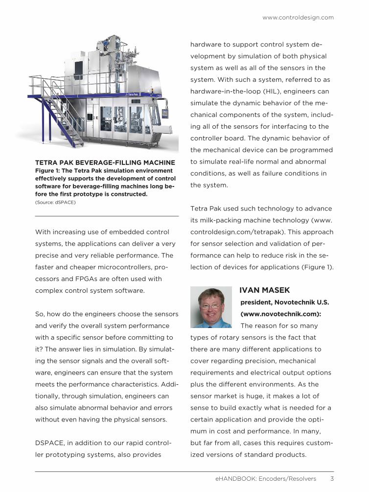
Tetra Pak used such technology to advance
its milk-packing machine technology (www.
controldesign.com/tetrapak). This approach
for sensor selection and validation of per-
formance can help to reduce risk in the se-
lection of devices for applications (Figure 1).
IVAN MASEK president, Novotechnik U.S.
(www.novotechnik.com):
The reason for so many
types of rotary sensors is the fact that
there are many different applications to
cover regarding precision, mechanical
requirements and electrical output options
plus the different environments. As the
sensor market is huge, it makes a lot of
sense to build exactly what is needed for a
certain application and provide the opti-
mum in cost and performance. In many,
but far from all, cases this requires custom-
ized versions of standard products.
www.controldesign.com
eHANDBOOK: Encoders/Resolvers 3
TETRA PAK BEVERAGE-FILLING MACHINEFigure 1: The Tetra Pak simulation environment effectively supports the development of control software for beverage-filling machines long be-fore the first prototype is constructed.(Source: dSPACE)
Use absolute position sensors in applica-
tions where you need to know the position
exactly after a power outage and cannot
move back to an index switch. In most other
applications, incremental can be a more
cost-efficient way to go. For ultra-high pre-
cision in a controlled manufacturing envi-
ronment, use optical encoders, though for
many applications this degree of precision
is not needed.
I recommend talking to an application engi-
neer from a manufacturer that shows appli-
cations similar to yours shown on his ap-
plication Web pages. This person can guide
you very quickly to a tailored solution by
asking detailed questions on performance
and environmental requirements as well as
size and cost.
JONATHAN DOUGHERTY product specialist, Heiden-
hain (www.heidenhain.com):
As the world becomes more and more auto-
mated, there has been a higher demand for
feedback devices suited for a variety of
applications. In order to meet these de-
mands, many encoder companies have
started offering a variety of solutions to
cover all possible applications, which has
produced the introduction of a variety of
scanning technologies and features specifi-
cally suited to handle different environ-
ments. However, the factors for determining
which encoder to use largely remain the
same. Establishing what accuracy you need,
the environmental conditions the encoder
must endure, such as vibration, contamina-
tion and temperature, and the mechanical
restrictions will go a long way toward
narrowing down the right product for you.
And of course, if you ever have any ques-
tions, we always encourage customers to
contact us so that we can help to answer
any of their questions and guide them to
the most effective solution.
CHIP MCDANIEL technical marketing,
AutomationDirect (www.
automationdirect.com): An
encoder is the popular choice for shaft
speed and position control. While a resolver
is popular for motor commutation and is a
robust option, in a servo motor, for exam-
ple, the encoder wins the popularity con-
test. There are a variety of encoder tech-
nologies, as well, but the optical encoder is
the popular choice. Here is a guide to pick
the right product.
Selection of an incremental or absolute
encoder output is application-specific and
often hardware-specific. Incremental en-
coders provide count and direction signals
and will work with high-speed PLC counter
modules for accurate position monitoring
and control. The position signal provided is
relative to a zero position where the coun-
ter was reset or powered on. Some absolute
encoders monitor position with gray code
www.controldesign.com
eHANDBOOK: Encoders/Resolvers 4

and standard PLC dc inputs. The absolute
position is retentive—it retains its position
data even after a power-off-to-on cycle.
Once the type of encoder—incremental or
absolute—and resolution are selected, the
housing type —duty-level, ingress rating—
must be selected. This is often called duty
level. This duty level includes light, medium
and heavy duty and includes a dustproof
IP40 or IP50 rating to splash-proof IP65 rat-
ing depending on housing construction.
After encoder resolution and housing type
have been determined, users must select
their preferred operating voltage and out-
put signals that they would prefer from the
various options.
The type of output must be carefully select-
ed. Line driver, differential, and NPN open
collector are probably the most common. A
line driver output refers to the fact that each
channel has a complement channel—Chan-
nel A and Channel A not. A differential line
driver is used to help increase noise im-
munity and works with either a sinking or
sourcing circuit. An open collector output is
an NPN transistor. An NPN transistor allows
the sinking of current to common. A voltage
supply through a load must be connected
to the output. In this case, a pull-up resistor
must be used. It is the load which pulls the
encoder output high when the output is off.
The controller input monitoring the encoder
open-collector output must sink the voltage
to the same common. The encoder output
voltages are wide ranging, with typical val-
ues of 12-24 Vdc, 5-30 Vdc and 10-30 Vdc.
NEIL BURGARD electric automation business
development specialist,
Festo (www.festo.com/us):
I recommend using an encoder over a
resolver. It’s smaller and lighter, a more
intelligent device for great flexibility and
capability, has a larger selection of shapes
and sizes, higher resolution for greater
accuracy and improved dynamics, is com-
patible with most controls and has a greater
diversity of network interfaces, as well as
lower cost and better availability.
Encoders are better in every way except
for when temperatures fall within 125 °C
to 220 °C, vibrations range from 20 G to
100 G, or if that is the only interface your
controls will accept.
The first step in selecting any encoder is to
figure out whether you need to know the
position as soon as power is applied. If you
do, then you require an absolute encoder.
Even if you don’t, I would still recommend
an absolute encoder over incremental
because absolute encoders offer higher
resolutions, faster speeds, better immunity
to noise and fewer wires—in some cases a
reduction from 14 wires to two). Start with
optical encoders because they produce the
highest resolutions, the best accuracy, fast
www.controldesign.com
eHANDBOOK: Encoders/Resolvers 5
speeds and the most options for voltage,
outputs, mounting, size, communications,
safety, cabling and vendors. Magnetic,
capacitive and inductive encoders have
a larger temperature range and are bet-
ter for shock, vibration and dust. Magnetic
and inductive encoders work best with
moisture and fluids. Magnetic are the most
tolerant of misalignment and can be very
low cost. The downfall is that they offer
lower resolutions and accuracy. Inductive
encoders are even more robust than mag-
netic and provide higher resolutions and
accuracy, but they cost more and require
tighter tolerances. Capacitive encoders
also offer higher resolutions and accuracy
and are lower cost, but they don’t operate
well with moisture and fluids. Capacitive
are also the best choice for battery appli-
cations because they use little power, or if
you need to change the resolution.
SCOTT ORLOSKY global market
segment manager,
Sensata Technologies
(www.sensata.com): I can understand the
frustration and confusion when confronted
with so many options. First you will need to
decide if you need to know absolute posi-
tion, even if the power is turned off and then
turned back on again. If so, you will need to
choose an absolute type of product. Most
resolvers will inherently provide an absolute
position. Optical encoders can be absolute
or incremental. If you only require position
information relative to an index—provided
once per revolution with an incremental
encoder—and your primary concern is speed
control, then an incremental solution would
be the answer. Also, if your application can
use a homing sequence after power shut-
down without any problem, then an incre-
mental solution would work there, as well.
One other consideration is that absolute so-
lutions are generally more complex and ex-
pensive to install than incremental. Beyond
that, it depends on how much accuracy you
need in your application. Do not confuse
resolution with accuracy. High resolution
does not mean high accuracy. Designers
often assume that a higher resolution will
result in better performance of the sys-
tem. The reality is that higher accuracy and
repeatability are more important. Optical
encoders are the most accurate. Next are
resolvers and magnetic encoders. There are
other types of encoders, but they are not as
widely used, generally do not have as large
of an installed base and do not appear to be
any more accurate than optical encoders,
magnetic encoders or resolvers.
KATE SOKOLNICKI product marketing
manager for encoders,
Rockwell Automation
(www.rockwellautomation.com): When
choosing encoders, I recommend creating a
two-part checklist: electrical considerations
and mechanical considerations. With sens-
www.controldesign.com
eHANDBOOK: Encoders/Resolvers 6
ing technology—optical versus magnetic,
for example—technological advances lessen
the gap for many applications. Optical
sensors used to be recommended as higher
resolution, and, within that, glass code disks
recommended over metal or plastic, but
increasingly the same resolution can be
achieved in disparate sensing technologies.
Before selecting electrical specifications,
consider the maintenance of position after
power cycle or if the application requires
absolute position. Because they retain posi-
tion even after power loss, absolute encod-
ers tend to be more expensive. If this is not
required, choosing an incremental encoder
is recommended. For an incremental en-
coder, the user need only select the resolu-
tion—pulses per revolution—supply voltage,
output voltage and output signal type—
HTL, TTL, open collector or push-pull.
Absolute encoders offer more choices, with
both single-turn—pulses per revolution—
and multi-turn resolution—total number
of revolutions—options to select. Further,
many absolute encoders are configurable
over a network, such as EtherNet/IP or
DeviceNet. This allows the user to select the
exact resolution or to change the resolution
depending on the application.
Both incremental and absolute encoders
have the same mechanical considerations.
What size housing do you need? Do you
prefer a cable or connector? What size
shaft will the encoder be coupled to? Would
you prefer a hollow shaft or solid shaft?
Hollow-shaft options typically require a sep-
arate tether for mounting, which may have
a few options, while a solid shaft encoder
requires a flexible coupling.
TERRY HADDOCK senior applications engi-
neer, Encoder Products
(www.encoder.com):
There are many types of encoder solutions,
and each has its own benefits. Optical
encoders typically are capable of higher
resolution and accuracy. Magnetic encod-
ers are more resistant to environmental
contamination. Capacitive encoders are
also resistant to contamination, while offer-
ing less power consumption.
While these differences are very important
to encoder selection, there are also several
more factors when it comes to selecting
any electronic device: quality/reliability,
availability/delivery and support. In many
encoder applications, any type of encod-
er—optical, magnetic or capacitive—can
be used without any noticeable difference.
I wish there was a simple checklist to as-
sist with this complex decision. Due to the
many types of encoders and many different
performance specifications I don’t believe
this checklist will ever be simple. I believe
that selecting a supplier who can help you
through this process may be just as impor-
tant as the checklist itself.
www.controldesign.com
eHANDBOOK: Encoders/Resolvers 7

MARTY CWACH product manager, sensors,
Turck (www.turck.us):
Having a quick checklist
would be helpful, but the applications
would have to be very clearly defined, as
well. Almost always, the applications are not
clear and there are multiple variables to
solve simultaneously. This is the reason for
the variety of technologies, packages and
configurations.
ROBERT MILLER director, advanced testing
group, IVC Technologies
(www.ivctechnologies.
com): There are so many options because
there are so many individual uses and
applications for specific encoders and
resolvers. Many manufacturers provide very
good selection tools and aids to guide the
customer in the right direction, but that is
based on the assumption that the customer
really knows both what he wants and what
he needs. It is also important to keep in
mind the future needs, as opposed to
simply focusing on the immediate needs to
satisfy a performance spec. For example,
when given the choice of getting an encod-
er with or without an absolute phase mark-
er, I will always opt for getting the encoder
with multi-pulse and z-marker pulse out-
puts. I may only need the marker pulse for
basic vibration and process analysis appli-
cations; however the multi-pulse output
gives me the option for much more ad-
vanced analysis and diagnostic methods, if
and when they are needed. If this isn’t taken
into consideration at the time the encoder
in question is specified and procured, then
it’s too late when the problem that requires
this type of data and this type of analysis
occurs and you don’t have it.
With process data acquisition (PDA) sys-
tems becoming more and more prevalent, it
is also good to make provisions for redun-
dant outputs so one set of signals can be
dedicated for controls only, and one set of
outputs is strictly for process data analytics.
MARK LANGILLE technology planner, Dy-
napar (www.dynapar.com):
This is a complex topic, but
some of the high-level concerns involve
choosing between incremental single
channel and incremental quadrature or
absolute vs. resolver feedback. This chart
has quick guidelines (Figure 2, next page).
CHRISTIAN FELL COO, Posital-Fraba
(www.posital.com): Resolv-
ers can be very useful. They
are physically robust, relatively inexpensive
and have a wide temperature range. How-
ever, they also have significant limitations.
Resolvers are analog devices which require
an A/D converter in the controller interface.
They are also relatively low-accuracy devices
and do not have multi-turn capabilities.
www.controldesign.com
eHANDBOOK: Encoders/Resolvers 8
Encoders used to be more expensive but
recent developments in magnetic mea-
surement technologies have made them
more competitive with resolvers. Encod-
ers can offer very high levels of resolution,
accuracy and dynamic response, which
make them suitable for almost all applica-
tions. Incremental encoders can be a good
choice for speed control applications, while
absolute encoders offer advantages for
position control applications. Multi-turn
absolute encoders can also be very useful
for motion control systems with extended
ranges of motion.
The wide range of encoder options, while
confusing at the first glance, is an advan-
tage for users, since it makes it possible to
obtain a device that meets an application’s
full gamut of requirements. This included
performance specs (resolution, dynamic
response and measurement range) and
extends to system integration needs such
as preferred communication interface, level
of environmental protection and mechani-
cal interface features. We recommend that
users begin by defining their full require-
ments and then go to the market to find
no-compromise solutions. Product-finder
tools are designed to allow users to select
the functional characteristics that they
need and then zero in on the products that
meet their requirements.
www.controldesign.com
eHANDBOOK: Encoders/Resolvers 9
Incremental Absolute
Single-channel Quadrature
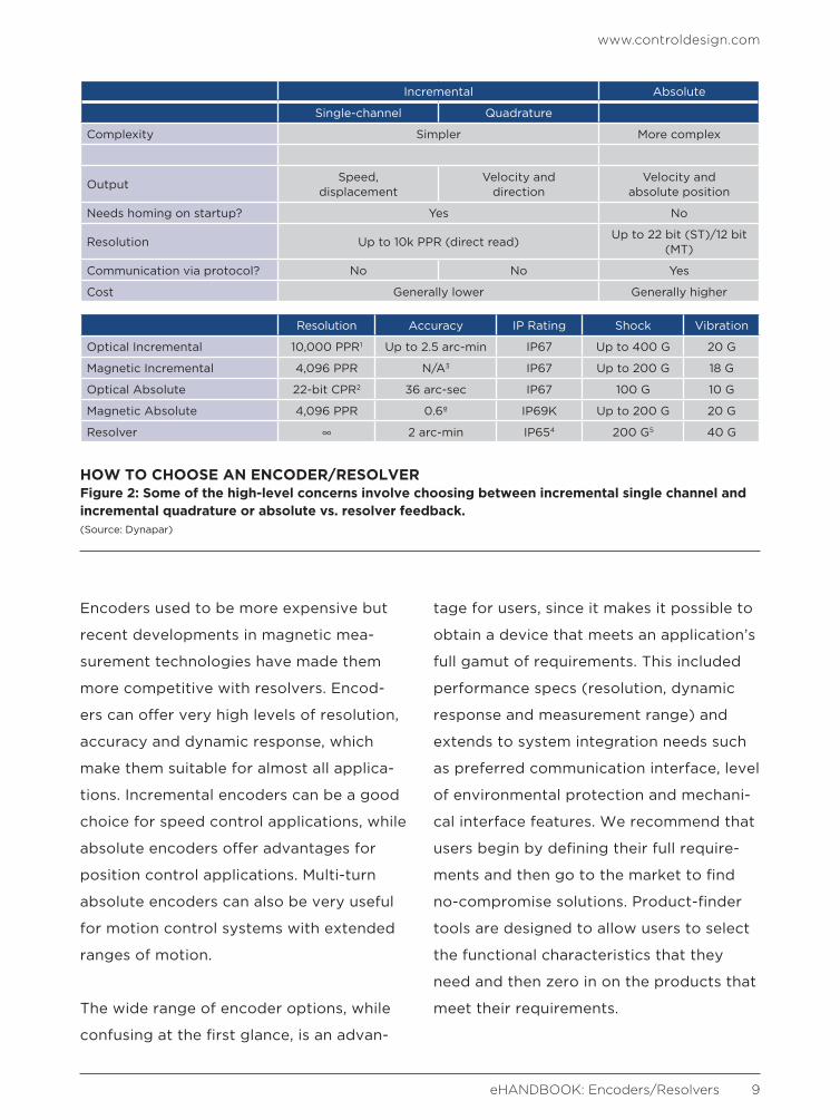
Complexity Simpler More complex
OutputSpeed,
displacementVelocity and
directionVelocity and
absolute position
Needs homing on startup? Yes No
Resolution Up to 10k PPR (direct read)Up to 22 bit (ST)/12 bit
(MT)
Communication via protocol? No No Yes
Cost Generally lower Generally higher
Resolution Accuracy IP Rating Shock Vibration
Optical Incremental 10,000 PPR1 Up to 2.5 arc-min IP67 Up to 400 G 20 G
Magnetic Incremental 4,096 PPR N/A3 IP67 Up to 200 G 18 G
Optical Absolute 22-bit CPR2 36 arc-sec IP67 100 G 10 G
Magnetic Absolute 4,096 PPR 0.6º IP69K Up to 200 G 20 G
Resolver 2 arc-min IP654 200 G5 40 G
HOW TO CHOOSE AN ENCODER/RESOLVERFigure 2: Some of the high-level concerns involve choosing between incremental single channel and incremental quadrature or absolute vs. resolver feedback.(Source: Dynapar)

For shaft speed and position control, the sensing options are almost limitless. Just as
infinite are the possibilities of applications that resolvers and encoders can be used
for, some of them more interesting than others. Our panel of experts shares some of
the more interesting applications they’ve encountered.
Can you share details about the most interesting or innovative use of an encoder or a resolver that you’ve ever seen?
KATE SOKOLNICKI product marketing manager for encoders, Rockwell Automation
(www.rockwellautomation.com): Some of the more interesting use cases
I’ve seen are for monitoring speed of a vehicle, either on a track for enter-
tainment applications or autonomous for AGVs.
NEIL BURGARD electric automation business development specialist,
Festo (www.festo.com/us): Using an inductive encoder on top
of a profile bearing rail is unusual.
11 most interesting encoder/resolver applicationsThe options seem unlimited and so are the ways encoders and resolvers are being used; here are 11 that are noteworthy
By Mike Bacidore, editor in chief
www.controldesign.com
eHANDBOOK: Encoders/Resolvers 10
www.controldesign.com
eHANDBOOK: Encoders/Resolvers 11
RICHARD HALSTEAD president, Empire Magnet-
ics (www.empiremagnetics.
com): Beam lines are inter-
esting. The need for centralized data over a
large facility, while at the same time sup-
porting closed-loop functions, makes it
technically challenging.
Research centers are now built around
beam lines. Typically beam lines are in a
vacuum, and many produce radiation. In
addition, the facilities are large. Motion
systems that are involved with the control
and direction of the beam are typically
high-precision and require feedback to
provide the desired functions. One exam-
ple facility is the Advanced Light Source
(ALS) at Lawrence Berkeley National Lab
managed by the University of California.
To address the requirements of motors
and feedback that operate in vacuum
while subject to radiation dose, Empire
Magnetics provides stepper motors with
resolver feedback. Micro-stepping drives
combine with 200 step motors to provide
resolutions of 25,000, 36,000 and 50,000
counts per revolution. Such resolution
supports submicron positioning of devices
around the facility.
However, these microstep motor drives
are not typically resolver-compatible, and
encoders are not typically suitable for the
environment; in addition the facility opera-
tors would like to have information in their
centralized control room, which can be a
significant distance from the device. To
accommodate these requirements, Empire
Magnetics designed a set of electronics
that reads the resolver information, makes
it available in incremental encoder format
compatible with closed-loop drives, but
also makes positional information available
over Ethernet. Each of the products has
customer set hardware addresses, so many
units can be on one network. This approach
allows for the information to be presented
in the control room, but the use of Ethernet
avoids the cost of multiple cable runs.
Microstep motor drives are not typically resolver-compatible, and encoders are not
typically suitable for the environment.
www.controldesign.com
eHANDBOOK: Encoders/Resolvers 12
CHRISTIAN FELL COO, Posital-Fraba
(www.posital.com): No
single example comes to
mind, just the sheer spectrum of applica-
tions, from medical to off-highway and from
simple speed control to complex multi-axis
positioning. Also, declining costs and the
rise of IoT are driving the trend toward the
use of such sensors in more applications.
JONATHAN DOUGHERTY product specialist,
Heidenhain (www.heiden-
hain.com): As a company providing feed-
back, we are in a lot of interesting and
emerging technologies that are exciting to
see, such as collaborative robots, automat-
ed vehicles, and smart factories but one of
the coolest and most satisfying projects we
have been a part of is with a team develop-
ing an exoskeleton suit to assist paraplegics
to walk again. Beyond just the appreciation
for the amount of intelligence and technol-
ogy involved in this endeavor, it feels
rewarding to be a part of such a project,
which can help aid a person to walk again.
CHIP MCDANIEL technical marketing, Auto-
mationDirect (www.automa-
tiondirect.com): Check out
the video, “Triple Pendulum on a Cart,” (www.
controldesign.com/triplependulum). This is
my favorite application for encoder and one
of my favorite Youtube videos of all time. I
think anyone with some technical knowledge
will realize just how hard this is from a con-
trols standpoint. Although it is not really in
the industrial arena, there are industrial
applications where this type of positioning
technology can be used to great advantage.
The following is a quote from Andreas
Eder’s and Tobias Glück’s scientific paper
on the project (www.controldesign.com/tri-
plependulumpaper). “Incremental encoders
at each joint measure the different angles
between two adjacent arms and between
the first arm and the cart, respectively, with
a resolution of 4.395 × 10⁻²°. In order to
keep the friction low, the signals are trans-
mitted contactless via an optical connection
from the joints to the control unit.”
I’m reminded of Arthur C Clarke’s Third
Law, “Any sufficiently advanced technology
is indistinguishable from magic.”
MAHENDRA MULI director of marketing and
new business development,
dSPACE (www.dspaceinc.
com): We often see our customers do
amazing innovative control system applica-
tions using the encoder or resolver sensors
across the industries, from automotive and
aerospace to commercial on- and off-high-
way vehicles and medical devices.
Cleveland State University recently de-
signed a dynamic, adaptable exercise ma-
chine for enhanced physical training using
www.controldesign.com
eHANDBOOK: Encoders/Resolvers 13
motors and control systems to generate
continuously adjustable mechanical imped-
ances for better user interactivity. More
information can be found at www.contr-
oldesign.com/smarttraining (Figure 1).
IVAN MASEK president, Novotechnik U.S.
(www.novotechnik.com):
Some of the coolest applica-
tions for sensors we have worked on very
successfully in the past are the lean-steering
of the Segway i2, the wakeboard wave-con-
trol-surface angle measurement on pleasure
crafts from Malibu Boats and the position
measurement of the visitor glass platform
on the Willis Tower in Chicago. They are all
featured at www.controldesign.com/novo-
technikapplications.
TERRY HADDOCK senior applications engi-
neer, Encoder Products
(www.encoder.com): One
interesting encoder application involved
“Wheel of Fortune.” The plan was to incor-
porate high resolution screens in place of the
cardboard cutouts placed on the wheel. An
encoder would be used to track position and
allow the show to know on which prize the
spin had landed. This would allow for more
involved prize images and quicker change-
over during commercials. This design was
quickly scrapped, as producers were con-
cerned that they would lose viewers if any
suspicion arose that the game was rigged.
SCOTT ORLOSKY global market segment
manager, Sensata Technol-
ogies (www.sensata.com):
Perhaps the most visually stunning are
these elaborate stage acts, with lots of
moving stage platforms, traveling trapeze
artists, sets that spring up out of nowhere
and disappear and so on. They really are
quite spectacular to watch and rely heavily
on a carefully choreographed set of ma-
chine instructions and feedback devices
working with split-second timing.
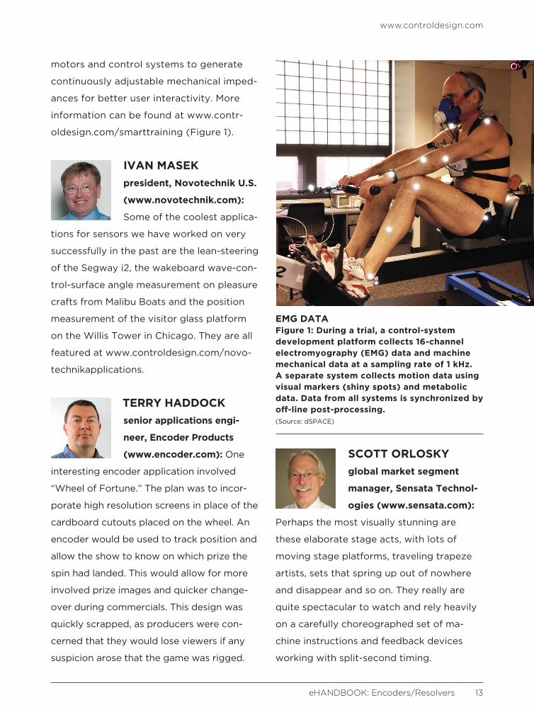
EMG DATAFigure 1: During a trial, a control-system development platform collects 16-channel electromyography (EMG) data and machine mechanical data at a sampling rate of 1 kHz. A separate system collects motion data using visual markers (shiny spots) and metabolic data. Data from all systems is synchronized by off-line post-processing.(Source: dSPACE)
www.controldesign.com
eHANDBOOK: Encoders/Resolvers 14
MARTY CWACH product manager, sensors,
Turck (www.turck.us): Turck
helped to provide sensor
selection and support for position feedback
on vehicles used to gather data to map
streets/roads, which is ultimately used in
navigation software. The customer had
difficulty with longevity of the encoders, as
they were applied to the wheel of the
vehicle. The encoders happened to be
failing during the vehicle’s cleaning, or car
wash, operation. Once we saw photos of
the installation, we could quickly under-
stand that the selection and placement of
the encoder needed to be reviewed to help
to prevent premature failure. The original
encoder did not have adequate ingress
protection and the cable routing allowed for
a drip line/water path directly into the
electrical connection of the encoder. We
improved the encoder life by offering a
solution with higher IP and recommended a
drip loop for the connection cable.
The engineer involved had said that he was
given a set of electrical requirements that
the original encoder satisfied very well.
Even when testing the vehicle for the first
few weeks, all was well with the original de-
sign, as it had not rained and there was no
reason to wash the vehicle. As soon as the
customer had a few vehicles wrapped with
logos/decals and advertising, they would
wash it nearly every day to keep it clean
and presentable. Those operations and
requirements to survive washdown changed
the durability requirements of many sensors
from the original specification.
ROBERT MILLER director, advanced testing
group, IVC Technologies
(www.ivctechnologies.
com): The most interesting application that
I have been involved in is torsional analysis
using encoders. Traditionally it is necessary
to mount strain-gage-based torque telem-
etry on rotating shafts of a drive assembly
to observe and measure the torsional
characteristics. This often requires signifi-
cant downtime, and, because the transmit-
ters are often battery-powered, thus the
effective measurement window can be
extremely limited. In contrast, by taking the
encoder pulse train and running it through a
torsional frequency-demodulation routine
available in off-the-shelf packages such as
ibaRotate, the torsional frequencies within
the range of the specific encoder can be
evaluated at any time during operation
without requiring downtime. In addition,
since the encoder pulse count effectively
becomes the sampling rate for spectrum
analysis in the angular domain; the higher
the pulse count, the higher the torsional
frequency range that can be evaluated.
If pulses can be obtained from both ends
of a given shaft, you can use variations of
these same routines to look at shaft twist/
windup, from which an approximation of

www.controldesign.com
eHANDBOOK: Encoders/Resolvers 15
the actual shaft torque can also be derived.
Simply put, these two routines allow not
only the evaluation of conditions such as
torsional resonances, but also the torsional
influence of key mechanical components
such as couplings, bearings and gearing.
This is in comparison to merely looking at
the shaft rotation speed. There also exist
calibration routines that allow for the usage
of low-cost encoders with uneven/jittery
angular spacing.
MARK LANGILLE technology planner, Dy-
napar (www.dynapar.com):
Dynapar produced large
bore magnetic encoders for an engineering
services company that installed cables on
the largest suspension bridges in the world.
The encoder wheel adapter IDs were 6
inches in diameter. It is always impressive to
see how the mechanical power of motor,
gearbox and electronic control can be
synchronized together to move mountains
or in this case cross them. The encoder
provided the link between the mechanical
motion and the control.
The output from an encoder needs to match the input of the controller, but don’t
be fooled by some of the tricky hurdles. Resolution has some stumbling blocks of
its own, as well. Our panel of experts makes you aware of the potential hazards to
keep your eyes peeled for.
When matching the output to the controller’s input, what tricky hurdles do machine builders sometimes overlook? And what about resolution—any potential stumbling blocks to note?
CHRISTIAN FELL COO, Posital-Fraba (www.posital.com): Not all interfaces are well-standard-
ized. This can be especially tricky in the MRO business when supposedly
“drop-in” substitutes turn out to be incompatible.
When it comes to resolution we often see that products are overspecced by the customer—
for example, 16-bit ST for a concrete boom pump. To keep costs low, encoder performance
should meet a realistic set of mechanical and performance requirements of the application.
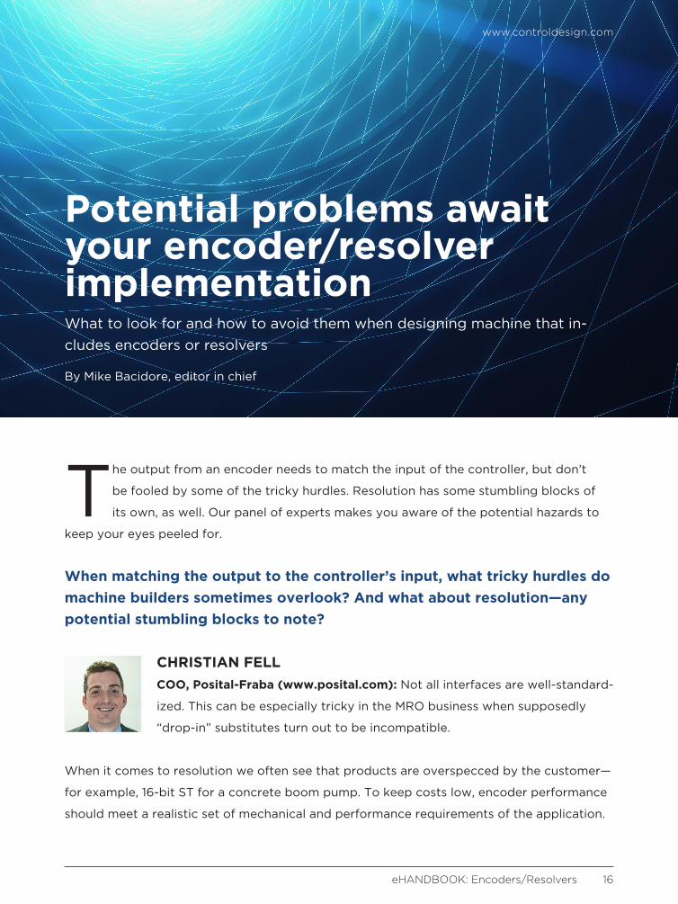
Potential problems await your encoder/resolver implementationWhat to look for and how to avoid them when designing machine that in-cludes encoders or resolvers
By Mike Bacidore, editor in chief
www.controldesign.com
eHANDBOOK: Encoders/Resolvers 16
www.controldesign.com
eHANDBOOK: Encoders/Resolvers 17
JONATHAN DOUGHERTY product specialist, Heiden-
hain (www.heidenhain.com):
One major hurdle we see is when machine
builders try to choose from the many
different encoder protocols available on the
market today. Often many machine builders
aren’t aware of all the different terminology
used by different encoder companies, and it
can become quite confusing when looking
through protocol options. The best way to
solve this is to have direct conversations
with your encoder suppliers and push for
apples-to-apples comparisons on the
specifications required.
IVAN MASEK president, Novotechnik U.S.
(www.novotechnik.com):
Regarding the use of poten-
tiometer-based sensors on, for example,
injection-molding machines, presses, valve
control and dancer arm applications, it is
important to use high-impedance inputs:
greater than 10 MegOhm on the PLC.
Use shielded cables on potentiometers and
Hall-effect sensors to minimize noise and con-
nect the shield only to measurement ground
on the PLC, and do not connect the shield to
the sensor housing. This will prevent ground
loops and ensure a noise-free signal.
A common error is mistaking resolution for
accuracy and repeatability. For processes
that must come to the same position re-
petitively—for example, indexing tables,
assembly processes—repeatability is gen-
erally the more important consideration.
For the same sensor output, how close are
you to arriving at the same position every
time? Higher resolution does not always
mean higher repeatability.
Specific interfaces have their own unique
potential stumbling blocks. Serial periph-
eral interface (SPI), synchronous serial
interface (SSI) and CANopen each has its
own specific considerations. In general,
take care to make sure the manufacturer’s
device matches the requirements of the
master controller.
Use shielded cables on potentiometers and Hall-effect sensors to minimize noise
and connect the shield only to measurement ground on the PLC, and do not connect the
shield to the sensor housing.

www.controldesign.com
eHANDBOOK: Encoders/Resolvers 18
Avoid installing sensor wiring in the same
conduits as power lines for other devices,
such as motors, to avoid noise problems.
TERRY HADDOCK senior applications engineer,
Encoder Products (www.
encoder.com): Matching the
encoder output to controller input can be a
hurdle. Most of the new PLCs, high-speed
counters and controllers have the ability to
accept many different encoder outputs. The
tricky part is configuring the device to match
the encoder. Referring to the manual or
contacting the controller manufacturer can
help to configure the device properly.
If a user does not know which encoder out-
put to select, I recommend differential line
driver. The encoder output line driver IC has
the ability to either sink or source current,
as well as supply differential signals. This
gives the user the most options for match-
ing the controller input.
Encoder resolution is extremely important
to system control. In a perfect system,
higher resolution gives you tighter control.
Unfortunately, no system is perfect. It is im-
portant to know the maximum error within
a system before selecting encoder resolu-
tion. Ideally a user will select a resolution
slightly better than the system error. Select-
ing a resolution that is much larger than the
system error will cost more and not result in
improved control.
SCOTT ORLOSKY global market segment
manager, Sensata Technolo-
gies (www.sensata.com):
Designers often try to push for higher resolu-
tions, but there is a trade-off between
resolution and speed. Also, at some point in
increasing resolution, you reach the accuracy
limit of the device and further increases to
resolution are counterproductive. Look at all
of the physical errors in your system—wind-
up, backlash, deflection, timing, propagation
delays in control—to figure your total error
budget and use that to determine the accu-
racy your feedback device will require. Pick
your resolution accordingly.
NEIL BURGARD electric automation
business development
specialist, Festo
(www.festo.com/us): For incremental
encoders, you need to make sure the
pulses from the encoder don’t exceed the
max frequency of your encoder input.
For very long cable runs you need to make
sure you don’t have too much voltage drop.
Watch out for electrical noise on your incre-
mental encoders. This can cause havoc with
your controller. Make sure your cable shields
are grounded, and keep the encoder lines
away from things like motor power lines.
Not all network encoders, such as Modbus
TCP, work well at high-speed controls.
www.controldesign.com
eHANDBOOK: Encoders/Resolvers 19
MAHENDRA MULI director of marketing and
new business development,
dSPACE (www.dspaceinc.
com): Engineers always consider signal
conditioning and filtering requirements
while matching the sensor output to the
control device. However, the impact of such
additional hardware, such as delay or drop
in resolution, should be considered on the
overall system performance. It is easier to
evaluate such impacts using simulation
technology. With dSPACE systems, engi-
neers can easily and quickly simulate the
controller software, as well as the additional
delays, noise and sensor signal distortion
effects, using model-based design. This
ensures that all potential stumbling blocks
that could potentially happen are discov-
ered early in the machine design stage.
ROBERT MILLER director, advanced testing
group, IVC Technologies
(www.ivctechnologies.
com): As a diagnostics guy, when it comes
to resolution I always want more. That
being said, I also need to be able to objec-
tively look at the application and determine
how much is enough and how much is too
much. If I have too many pulses or too
much resolution, it will probably result in
additional requirements with regard to data
acquisition such as dedicated counter-timer
channels sampling at much higher rates that
will still need to synchronize with the lower
speed channels handling the process data
acquisition. If things are too snappy and too
responsive it can also be an issue from a
controls stability standpoint since you can
end up chasing the noise. The resolution
should be high enough to allow accurate
evaluation and diagnosis of any of the
known or anticipated issues that may be
encountered and leave a little bit of margin
for Murphy.
RICHARD HALSTEAD president, Empire Magnet-
ics (www.empiremagnetics.
com): For resolvers with
long cables, the excitation frequency be-
comes a factor. The higher the frequency,
the higher the cable impedance, or the
shorter the cable that can be supported.
The lower the frequency, the lower the
rotational speed that the system can read.
For radiation areas, the cables must be
routed around shielding to protect people.
It is a real challenge to get a cable that is
made of radiation-resistant materials and
still has the reactance low enough to sup-
port long cable runs.
KATE SOKOLNICKI product marketing manager
for encoders, Rockwell
Automation (www.rock-
wellautomation.com): The output signal
type will depend on where you are taking
the encoder feedback—to a high-speed
counter card, to a relay or to a drive?
www.controldesign.com
eHANDBOOK: Encoders/Resolvers 20
Networked encoders, such as the Allen-
Bradley Bulletin 842E EtherNet/IP Encoder
from Rockwell Automation, simplify this
decision by allowing the user to bring speed
and position feedback directly into the
controller, with no need for a high-speed
counter card.
MARK LANGILLE technology planner, Dy-
napar (www.dynapar.com):
For incremental encoders,
it’s beneficial to use twisted pair, with foil
and braided shield whenever possible.
Selecting a cable with less than 35 picoFar-
ads/ft is important in applications more
than 30 ft to reduce the capacitance in the
cable. As the rpm and pulses per revolution
(PPR) increase this becomes a critical
factor. This is crucial in applications such
as servo motors that may have both high-
speed and low/zero-speed motion profiles.
An absolute encoder with an all-digital
interface can alleviate equipment techni-
cians from having to chase ghosts in the
equipment due to a host of analog artifacts
that are common in industrial applications.
The latest protocols offer a single cable for
motor power and encoder signal. This
offers the machine builder the best of both
worlds—high-bandwidth 20-bit encoders
with reduced cabling and plug-and-play
capability.
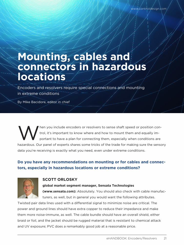
When you include encoders or resolvers to sense shaft speed or position con-
trol, it’s important to know where and how to mount them and equally im-
portant to have a plan for connecting them, especially when conditions are
hazardous. Our panel of experts shares some tricks of the trade for making sure the sensory
data you’re receiving is exactly what you need, even under extreme conditions.
Do you have any recommendations on mounting or for cables and connec-tors, especially in hazardous locations or extreme conditions?
SCOTT ORLOSKY global market segment manager, Sensata Technologies
(www.sensata.com): Absolutely. You should also check with cable manufac-
turers, as well, but in general you would want the following attributes.
Twisted pair data lines used with a differential signal to minimize noise are critical. The
power and ground lines should have extra copper to reduce their impedance and make
them more noise-immune, as well. The cable bundle should have an overall shield, either
braid or foil, and the jacket should be rugged material that is resistant to chemical attack
and UV exposure; PVC does a remarkably good job at a reasonable price.
Mounting, cables and connectors in hazardous locationsEncoders and resolvers require special connections and mounting in extreme conditions
By Mike Bacidore, editor in chief
www.controldesign.com
eHANDBOOK: Encoders/Resolvers 21

www.controldesign.com
eHANDBOOK: Encoders/Resolvers 22
If possible, use a cable/connector assembly
with an overmolded backshell, which will
be more resistant to water intrusion. The
cable termination should be done in an en-
closure that cannot get wet. Any moisture
that enters an open cable end will eventu-
ally work its way down to the connector
and cause corrosion. Also make sure that
the cable is installed with a generous radi-
us to prevent mechanical damage through
flexing and be sure to control the geom-
etry of the cable lead-in to the encoder, so
that it is not loose and subject to snagging.
In general, the cable should lead down and
away from the encoder so that any mois-
ture will drip off the cable, rather than pool
around the connector.
NEIL BURGARD electric automation business
development specialist,
Festo (www.festo.com/us):
For extreme conditions, use grommet with
cable instead of a connector on the encoder.
ROBERT MILLER director, advanced testing
group, IVC Technologies
(www.ivctechnologies.
com): The more protection, the better, and
it will always be money well spent. Often
times the pencil gets sharpened during the
specification and procurement phase to
keep costs down, but these costs are typi-
cally insignificant when compared to the
equipment damage, production downtime
and general mayhem that can result when a
critical-speed reference signal fails. In these
situations it’s hard to justify the $50 savings
on a cheaper cable when the failure just
resulted in a $1 million loss due to un-
planned downtime and equipment damage.
There are some environments that are just
plain bad for instrumentation, and, in these
cases, it is also good to plan in redundan-
cies as an additional layer of protection.
In addition to cables and connectors, simple
things like shaft alignment and proper cou-
pling selection are crucial. Improper align-
ment results in the encoder shaft speed ac-
celerating and decelerating each revolution.
A worn coupling insert allows for an erratic
pulse train—speed/position error.
TERRY HADDOCK senior applications engi-
neer, Encoder Products
(www.encoder.com): To
extend the life of any encoder, I recom-
mend incorporating some secondary
protection beyond the housing included in
the encoder design. It may be as complex
as a hermetically sealed enclosure or as
simple as a shield to redirect liquid con-
tamination. I have even seen applications
where plastic bags have been the explana-
tion for encoder survival.
This type of protection can also help to
eliminate physical damage, as well. Cables
and connectors can easily be damaged
www.controldesign.com
eHANDBOOK: Encoders/Resolvers 23
when used as a step or handle on large
automated equipment. Installing a guard or
shield is much less expensive than replacing
a broken encoder or cable assembly, espe-
cially when you include machine downtime.
RICHARD HALSTEAD president, Empire Magnet-
ics (www.empiremagnetics.
com): In areas with explo-
sive hazards, a low-cost approach is to put
the cables inside pressurized conduits.
Following the NFPA 496 safety code, it is
possible to safely install systems without
going to expensive equipment.
Instead of installing long cables on the motors
that will be pulled into conduits and that must
later be cut or pulled out of those conduits
if there is a maintenance problem, the motor
is set up with a junction box located close to
the motor, and then a plumbing union is used
to allow for easy connect/disconnect from
the conduit. Removal of the motor without
removing long cable runs is a snap.
JONATHAN DOUGHERTY
product specialist,
Heidenhain (www.heiden-
hain.com): This is a great
question because it does feel at times that
the cabling and connectors are sometimes
left as an afterthought when, in fact, they
are such a critical part to ensuring that the
feedback loop works effectively and
efficiently. We here at Heidenhain take
great pride in the amount of research and
development we put in to ensuring that
the cables and connectors we provide are
tested to the extreme and are capable of
operating in the hazardous conditions we
see our customers encountering. This
helps to ease some of the burden from the
customer and allows them to feel com-
fortable that they are receiving a pre-ap-
proved solution with their feedback de-
vice. Some keys to ensuring a clean signal
are to verify the correct shielding concept
for the encoder and cable is used, as not
every encoder is the same, and to avoid
Some keys to ensuring a clean signal are to verify the correct shielding concept for the
encoder and cable is used, as not every encoder is the same, and to avoid installing signal cables near possible interference sources—contactors,
frequency inverters, solenoids.
www.controldesign.com
eHANDBOOK: Encoders/Resolvers 24
installing signal cables near possible
interference sources—contactors, frequen-
cy inverters, solenoids.
CHRISTIAN FELL COO, Posital-Fraba
(www.posital.com): Even
though most of our encod-
ers can handle high shaft loads, the use of
proper flexible couplings reduces bearing
wear and improves encoder service lives.
This is too often neglected. We have also
found that buyers look primarily at direct
encoder costs, without paying adequate
attention to system costs on the mechani-
cal or electromechanical side. Total system
costs can often be significantly reduced by
using an encoder with the right features.
For example, blind hollow shaft versions
can save space and eliminate the need for
external couplers.
There are often alternative mechanical
configurations and connector accessories
available that would make the job of inte-
grating an encoder into a design simpler
and less costly, if only the customer knew
that they existed. We have specifically de-
signed the Posital Product Finder so that
our customers can see the full range of
mechanical and performance options that
are available, without having to talk to a
product specialist.