Raco Jac-Rabbit Manual - CompetitionX
20
@ I Radio Controlled Off-Road Racer ASSEMBLY Af~D INSTRU T~ PERA1=ING NS Read and follow an the Information in Hl!S manual so that this product will provide you with hours of trouble f ee enjoyment. Pay close attention to the precautions thru-out '(he manual as safety is an We at RACO modelcratt take pride in the products we offer and invite any comments you may have. 1840 S. Santa Fe #A SGnta Ana CA 92705 .i
-
Upload
khangminh22 -
Category
Documents
-
view
5 -
download
0
Transcript of Raco Jac-Rabbit Manual - CompetitionX

@
IRadio Controlled Off-Road Racer
ASSEMBLY Af~DINSTRU T~
PERA1=INGNS
Read and follow an the Information in Hl!S manual so that this product
will provide you with hours of trouble f ee enjoyment. Pay close
attention to the precautions thru-out '(he manual as safety is an
We at RACO modelcratt take pride in the products we offer and invite
any comments you may have.
1840 S. Santa Fe #A SGnta Ana CA 92705
.i

SAFETY INSTRUCTIONS FOR THE JAC-RABBIT'"-WARNINGS-
1. Warning: Read The Owner's Manual before operating the car. Never allow anyone tooperate the car who does not understand the assembly and operating manual.
2. Warning: Do not operate the car unless you believe you understand all assembly andoperation instructions first. Please refer to your Owner's Manual.
3. Warning: The .Jac-Rabbit" is not a toy. If operated unreasonably or recklessly the Jac-Rabbit" can cause serious bodily injury. This product is not to be operated by persons under16 years of age without adult supervision. The supervising adult should understand theassembly and operation of the car before allowing anyone to operate the .Jac-Rabbit".
4. 'v'Varning: Check al fasteners and parts for looseness or damage before each operationand corred before starting the car.
5. Warning: Always check your radio control for proper operation before starting the car:Please see Owner's Manual.
6. Warning: Do not start the car unless the front of the car is resting against a solid heavyobject. Never switch "on" the radio gear without an immovable object in front of the car.
7. Warning: Always turn "on" the radio first and the car last. Always turn "off" the carfirst andthe radio last.
8. Warning: If other radio controlled models are running in your area of operation, be surethat no other radio with your ftequency is "on" while running your car.
9. Warning: Do not operate the .lac-Rabbit" near large metal structures as there may beradio interference.
10. Warning: Always operate the car in an open area free of bystanders. Never operate thecar when children or a. imals are nearby.
11. Warning: Always be certain your vision of the car is not obstructed by objects in the areaof operation; loss of sight of the vehicle means loss of control.
12. Warning: Although the Jac-Rabbit'" is an off-the-road car made for rough terrain youshould not use it for high jumping.
13. 'Warning: Do not accelerate the car to high speeds that could cause loss of control.
14. Warning: Use extreme care when handling gasoline during refueling. Gasoline isextremely flammable and dangerous. Do not refuel in an enclosed area or near an open flameor while smoking.
@1985 Raco ModelCraft, Inc.
Page1

Additional Equipment Required
The .Jac-Rabbit" Racer is semi-assembled fromthe factory and requires approximately one hour offinal assembly after painting.
The instructions in this manual will guide you step-by-step in the assembly and safe operation. How-ever, you may need additional equipment from yourlocal hobby store to make your car operational.
You will need the following items if they werenot ordered with your car:
1 - Two channel radio with receiver2 - Servos (Futaba S-34 or S-34L)1 - 15 minute quick charger suitable for a 5-cellbattery pack1 - 5 cell battery pack (consisting of five Sub-CNicad batteries)
RA[)~Q/RECEiVERYour car is designed to operate on most two chan-nel radio systems. However, some systems arebetter than others for this car. See the recom-mended radio list included.
If you already have a radio, you should have itserviced and re-tuned to insure the radio and re-ceiver are operating properly before installation inthe car.
If you purchase a new radio, be certain that itsfrequency is specifically for surface vehicles (i.e.boats and cars) 75MHZ or 27MHZ. It is iilegal tooperate this car on any other band. From factorytesting and experience a radio on 27MHZ bandsworks best.
In the event the receiver you use has a differenttype plug connector, you should ask your hobbydealer for adaptors to make the connection.
.J
Page2
BATTERY PACK (If not included)
The car's electrical system requires a 6-volt D.C.power pack. !\ pack of 5 Sub-C 1.2 volt Nicads,available at most hobby shops, will do the job. Donot use dry cell batteries. A plug is included for thebattery pack you purchase.
QUICK CHARGER (If not included)
For re-charging the battery pack, you will need a 15minute quick charge suitable for charging 5-cells.Some chargers are made for high voltage batteries.Be certain you get one for 5-cell or 6 volts.
WARNiNG:If you use a radio and' receiver that are not new, youshould have them serviced and retuned to insurethat they are operating properly before starting thecar.
SE RVOS (If not included)
The steering and throttle mechanisms are designedto use Futaba S-34 of S-34L servos. If not includedin the car kit, you will need two. The servo arms andlinkage are included. The throttle servo may need alonger wire to reach the receiver.
A new radio will come with servos included. How-ever, they are much smaller in size and power andshould not be used in the: .lac-Rabbit" Racer.

'ASSE~flBLY
Since the .Jac-Rabbit" is semi-assembled, youwill need only a small number of hand tools tofinish the job. They consist of:
5/32 Allen Wrench7/64 Allen Wrench3/8 Open End Wrench
7/16 Open End Wrench9/16 Open End WrenchExternal Snap Ring Pliers
1" PAINTiNGIf you wish to paint the parts of your car to give itthe personal touch, you should do so beforedoing any of the final assembly work. Only twoparts should be painted - the chassis and thebody. Remove the screws holding the el~gine/cage to the chassis before painting either part.You may want to sand the edges to remove anyburrs or roughness by using fine grain sand-paper.
Body Clips
~Chassis
.:::::'"MetricScrews
NOTE:The two screws that are holding tie chassis tothe engine are metric. Do not misplace them.Remove the body retaining clips before paintingthe chassis.
Page3
After sanding, clean each part in soap and waterand dry them thoroughly. In painting the chassis,it is recommended to use a primer before spray-ing the final color to make paint adhere to thealuminum surface. It is not necessary to use aprimer coat on the body, but you may do so to geta better finish.
Do not use lacquer paints on the plastic body asthey may cause damage to the surface. Anyenamel paint is usable, however Krylon spraypaint offers the easiest and best results for thenovice painter.
After the painting is completed, allow sufficienttime for the paint to dry then add the decalssupplied.

2. Rear Suspension
Shock Spacers(2) <«> Shaft Washers (4)
Shock Bushings (4)
After painting, your .Jac-Rabbit" is ready forassembly. Open the package containing the reartrailing arms, shocks and related parts. install theengine ignition module first using (2) 10-24x5/8screws and lock-nuts.
Connect the red module lead to one of the two (2)mounting screws for a ground. Afterthe engine isinstalled, connect the black module lead to theelectrical connector plug located under thecarburetor. These leads must be connected forthe engine to run.
Slide the center spacer onto the crosshaft. Slideboth trailing arms onto the rear crosshaft. Itmakes no difference as to left or right since botharms are the same.
Ignition Module
Page4
PO.)t;(.Fi the trailing arms and shaft, as shownbelow. Slip two of the shaft washers into the largeholes in the chassis from the inside.
NOTE:The shoulder of each shaft washer must fit intothe large chassis holes so that the step of eachwasher will face outward. It may be necessary tospread the chassis slightly. Place the remainingshaft washers (2) into the large chassis holesfrom the outside with their steps also fitting intothe large hole.
Shaft Washers (inside)I
4!t~ Shaft Washers (outside)
Install one 10-24x3/4 screw from each side thruthe shaft washers. Thread them into the cross haftand tighten securely with a 5/32 Allen Wrench.You may want to use Loc-Tite on these screws.
The arms should rotate on the shaft but will fitsnugly.
Do not install the shocks yet as they will be addedlater. Keep the remaining parts from the rearsuspension package together.

3. Front Suspension and ChassisOpen the front suspension package and learnthe component names from the photo below.
Shock Tower/
-Axle NutsCrossbrace 'll~JI'\
Servo Stands\\ /\I
Spindle Assy.(L & R)
-:
, ;/ ~Snock Spacer \ Tie Rod Spacer
Shaft Washer ~hOCk Bushings
Slide the shock towers and front assembly ontothe cage, engine and transmission assemblyusing the inner shock tower holes as shownbelow. Install two (2) 10-24x5/8 screws with tlatwashers into the roll cage threaded ends andtighten securely.
Slide each shock tower outward till the respectivefront trailing arms are resting against the retain-ing rings at each end of the cross haft. This willroughly position the shock towers for assemblyto the chassis. Install the front bumper using two(2) 10-24x3/4 screws. This will hold the shocktowers in place.
NOTE: The shock towersfit tightly on the cageends. Use the screws withwashers to pull the shock ,~ .towers onto the cage. f
Page5
Turn the engine, transmission and roll cageassembly with front crosshaft assembly attached,upside down on yourworkbench as shown below.
Lay the chassis on top and line up the holes forthe two primary engine mounting screws. Theseare the metric screws you removed to disassemblethe chassis from the engine just prior to painting.
Primary enginescrews
~@
Bulkheadscrews
Install the two primary engine screws but donot tighten them as yet. Theywill hold the chassisin place while installing the balance of hardwarefrom the bottom side.
Install the two (2) 10-24x 1/2 screws for the motorbulkhead.
Next install the six (6) 10-24x1 /2 screws for theshock towers. Again do not tighten them.

NOTE:Many of the holes in the non-metal parts such as
> the shock towers are not threaded but aredesiqned for self-tapping. Care must be taken notto over tighten and strip these screw holes.Tighten to snug only. Do not use Loc-Tite on anyof the nylon parts.
Tighten all the screws now installed from thechassis bottom side.
4. Front Shocks and Spindles
Slide one of the four shock bushings (brass) intothe shock hole at the spring end. Install a #10 flatwasher onto a 10-24x1 screw, slide the screw(with washer) thru the bushing and tighten a10-24 locknut against the shock bushing.
Mount all shocks wwith the spring
& shaft down ~2
Use super-glue to prevent loosening.
Thread the shock screw into the bottom hole (ofthree) in the trailing arm and tighten snugly. Use adrop of Super-Glue on the screw thread toprevent loosening.
NOTE:The three shock mount holes in each trailing armallow for the adjustment of ground clearance.Each higher hole will increase ground clearanceby approximately 1/4 inch. However, you willhave to space the tie rods upward also to provideclearance thru the full wheel travel.
Page6
Next install the top shock screw, (10-24x2)washer and bushing into the shock. Add theshock spacer and slide the screw thru the shocktower and thread into the crossbrace as shownbelow. Tighten securely. Use Loc-Tite if you wish.
Crossbrace
. Spring Collar
J/~
Follow the same shock mounting procedure forthe opposite side.
NOTE:The shoc <s are oil filled at the factory and mustbe installed "spring and shaft down" to insureproper suspension and handling. Reversing willproduce air pockets in the shock oil and poorhandling of the car. Also the front suspensionshould be "stiff". Adjust the front shock springcollars to 1 1/4 inches below the top screw hole.
Right\
<!,?,:<-
ICoded Red \
Left
Before installing the spindle assemblies, makenote they are assembled one left and one right.The right side will be color coded red on it'sshank.

With the tie rod arm poi nted to the rear of the car,install the red (right) spindle assembly into it'strailing arm. Slide a shaft washer onto a 10-24x1 /2screw with the washer's step nearest the screwhead. Thread the screw with washer into thespindle shank but do not tighten.
Shaft Washer
Right Spindle
The front end camber is not adjustable but set at2 degrees positive.
The caster however is infinitely adjustable. Forstarting out, adjust as shown below and tightenthe spindle shank screws securely.
Use the same procedure for the other spindleassembly installation.
Spindle Arm ----Trailing Arm
Stariing Caster Adjustment:Spindle arm parallel with trailing arm angle.
Page7
As you learn about your .Jac-Rabbit" you will findthat changing the caster angle greatly affects thecar's handling. Example: more caster angle willcorrect a car that has a tendency to spin out.General!y the .Jac-Rabbit" "likes" substantialcaster angle.
5. Tie Rods and Steering Linkage
Steering Pivot
First install the 1/4-28x1 3/8 pivot bolt from thebottom and tighten the 1/4-28 jamnut tightlyagainst the chassis floor. Install (2) 1/4 inch flatwashers onto the pivot bolt.
The steering mechanism has been assembledfor you at the factory. Place it beside the car asshown above.
To install it in the car, slide one tie rod betweenthe upper cage rail and chassis. Feed it thru bothsides until the steering pivot will slide onto thepivot bolt. It may be necessary to move the tierods about to slide the pivot onto the bolt.

Install a 1/4 flat washer and locknut. Tighten thelocknut so that the steering mechanism will turnfreely.
Attach the tie rods to the spindles using the10-24x1 screws. The spacer must be installed asshown below. Install the tie rods in the centerhole. If you want slower steering, move the tierods to the rear hole.
NOTE:The toe-in has been roughly adjusted at thefactory. Final adjustment will come after thewheels and tires are installed.
Move the spindles and steering mechanism fromlock to lock, ieft then right. There must be freemovement throughout the swing from left to rightstops. If a tightness is felt, find the source andcorrect it before proceeding.
PageS
6. Steering Servo and Fuel Tank
If your car was supplied with servos from thefactory, the steering servo has the linkage arm·nst21led install the servo as outlined below.
If your car was not supplied with servos, youmust use Futaba 5-34 or S-34L servos. Theproper servo arms have been supplied. Beforethe steering servo arm is installed, you must plugthe servo into the operating radio system for it tocenter itself. The arm must be installed perpendi-cular to the side of the servo.
Contact your hobby shop if help is needed.
Install the servo stands (2) with the notchesupwards and facing each other. Use 10-24x1 /2screws (4) from the bottom. The stands are notthreaded; they will self tap. Don't use Loc-Tite.

Install the steering servo with the am: to the rearand to the left.
Secure the servo in place with four 10-24x1 /2screws from the top. Do not over tighten as theservo housing will become distorted.
Connect the steering rod to the servo arm in thefourth hole from the outboard end. This willprovide a medium steering speed setting whichis good for learning to drive the car.
Install the 3/32 shaft collar below the servo armso that the steering rod will not come out. Use theAllen Wrench supplied.
As you become aquainted with the car and gainconfidence in your driving, you can move thesteering rod to the outer holes which will makethe steering faster.
Fuel TankBracket
<,
For mounting the fuel tank, first install one of thefuel tank brackets with two (2) 10-24x1 /2 screwsfrom the bottom but do not tighten.
Page9
Next slide the tank assembly under that bracket.Then install the second bracket from the oppositeside and tighten all four screws.
The tank has two fuel lines from it that connect tothe engine carburetor. The forward fuel line is thepriming pump return and must connect thecarburetor brass pipe closest to the air filter.
The otherfuelline is the fuel pickup and connectsto the brass fitting nearest the engi ne crank case.

7. Throttle Servo
If your car is supplied with servos from thefactory, the throttle/brake servo will already havethe linkage arm installed and it will be mounted onthe motor plate.
If servos were not included in your car kit, youmust purchase 2 Futaba 534 or S34L servos. Allother linkage and mounting hardware has beenincluded. Before installing the servo arm, you mustplug the servos into the operating radio system sothat the servo can center itself. Consult your localhobby shop for assistance. Also, the lead wire forthe throttle/brake may need to be lengthened toreach the receiver.
After centering, position the servo so the whiteoutput shaft is facing upward and to the right. Installthe throttle servo arm on the shaft so it is parallel tothe side of the servo case, with the angled arm endon the right. Install the small Phillips screw andtighten securely. Connect the single hole end of theslotted aluminum brake link to the No.2 hole- in theleft end of the servo arm using a 6-32 x 3/8 screw. Donot tighten.
Install the servo to the motor plate brackets fromthe bottom side using four 8-32 x V2 screws locknutsand flat washers. The lead wire should be on theright. Connect the slotted end of the brake link tothe plastic brake arm on the gearbox using asecond 6-32 x 3/s screw. Do not tighten as thelinkage must slide on the screw.
Slide the straight end of the wire throttle link (withshaft collar) into the slotted rotator on top of thecarburetor from behind the motor plate through theslotted opening. Bend the plastic servo arm down-ward to connect the throttle link to the No.2 hole inthe servo arm.
Page 10
Battery Power Pack
A. If your car kit was ordered without a BatterPower Pack; you will need battery pack consistinof 5 Sub-C size NI-CAD rechargeagle batterie:wired in series, with a plug compatible to thesupplied on the wire harness in the car. An :-ext!battery plug has been included should the batterpack you purchase not have the correct plug.
B. If your car kit was ordered with the BatterPack included; it will have the correct plug installed. Velcro strips are also included for mounting thbattery pack into the car chassis.
The oatt sry pack should be mounted directly ifront of the engine's starter and behind the fuel tanas shown below.
Non:::
Do not allow the battery plug pins to contact met,as a short circuit could occur.
8. Roll Cage Side Mounts
The roll cage mounts to the chassis at both sidejust in front of the engine using two (2) 10-24 xscrews, two (2) spacers and two (2) 10-24 locknutsSlip the screws through the chassis from the outside, install the spacers and slide the screwthrough the cage tube. Install the nuts and tighter

Spacer ~.
It may be necessary to flex the cage tubes toinstall the side screws.
9. Rear Axles and Shocks
Lift the rear trailing arm to it's highest point. Slipthe rear axle into the transmission drive cup byaligning the pins and slots. Do not slide the axleall the way into the cup, only far enough for thepins to barely engage the slots. This allows forthe maximum axle angle while inserting theopposite axle end into the wheel drive cup.
It is best to rotate the transmission drive cup sothat it's slots are horizontal before installing theaxle. Next rotate the wheel drive CI.'p so that it'sslots align with the axle pins.
Page i 1
It will be necessary to lightly force the trailing armupward to allow the axle to fall into the wheeldrive cup. Once the axle has engaged then lowerthe trailing arm to it's normal position. Install thesnap rings onto both drive cups.
To install the shocks, first slide one of four (4)brass shock bushings into the spring end of theshock and insert the shock end (with bushing)into the trailing arm as shown below. Install thelower shock screw 10-24x1 from the side into thefront hole in the trailing arm. Install a 10-24locknut and tighten.
The two (2) shock locations in the trailing armprovide for two ratios of shock/spring action. Thefront hole provides a softer ride while the rear110lewill stiffen H18 rear suspension. For startingout, the front hole is best.
Put a -#10 flat washer and a brass shock bushingonto one of the 10-24x1 3/8 upper shock screwsand slide it thru the upper shock hole. Install therear shock spacer and mount the top of the shockin the middle hole in the bulkhead. Again thereare three (3) holes to allow for adjustment of therear suspension spring rate. The rear hole willmake the ride stiffer. The front hole will make theride softer.
Rear Shock Spacer
You will find the upper shock nuts somewhathard to get to, but a 3/8 inch open end wrenchinserted from below, as shown above, will do thejob.
Assemble the axle and shock for the other sideusing the same procedures.
10. Wheels and Tires
The wheels and tires have been assembled foryou so that all that is needed is to install them onthe car.
In the rear use four(4) 10-24x5/8 screws with flatwashers per wheel. Install the wheel so that theallen head screws face outward.
Page 12
NOTE:The tires are not glued onto the wheels. If youintend to race the .Jac-Rabbit", you should dis-assemble the wheels from the tires and usesuper-glue to bond the wheels to the tire beads.
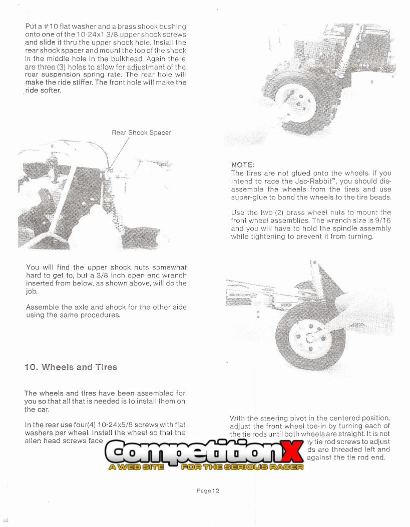
Use the two (2) brass wheel nuts to mount thefront wheel assemblies. The wrench size is 9/16and you will have to hold the spindle assemblywhile tightening to prevent it from turning.
With the steering pivot in the centered position,adjust the front wheel toe-in by turning each ofthe tie rods until both wheels are straight. It is notnecessary to remove any tie rod screws to adjustthe toe-in as the tie rods are threaded left andright. Tighten the nuts against the tie rod end.

11. Radio Receiver
Your Jac- Rabbit'" is nearly finished except for theinstallation of the radio receiver. Using the servotape supplied, mount it as shown below.
Receiver
WARNING:
The receiver you use must be tuned to the radioyou intend to use and mounted as shown. Themanufacturerwill not be responsible tor mcidentsinvolving mistuned radio gear Of" incorrectiymounted receivers. You should have the tuningchecked before installing the receiver in the carand periodically checked to insure proper radiogear function.
/Receiver & Servo Plugs
Plug in the leads from the battery, the steeringservo and the throttle/brake servo.
Page13
Route the antenna over the tie rod and up thruthe remaining hole adjacent to the front bumperas shown.
Feed the antenna wire thru the antenna tube sothat aproximately 1 inch sticks out the upper end.

Push the antenna tube into the shock tower holeuntil approximately 6 inches remain above theshock. Restrain the antenna tube to the shockusing one of the tie wraps supplied. The antennashould be as vertical as possible.
Gather up and tie the remaining antenna wire asshown. Do not shorten the antenna wire.
WARNING:
Never alter the antenna wire length or mount theantenna other than shown. Altered wire length ormounting closer to the engine may causeradio interference and control loss, for which themanufacturer is not responsible. If you encountera servo "twitching" or minor reception problem,raise the antenna 3-6 inches higher. If theproblem remains then have your radio & receiverretuned.
12. Charging the Batteries
Connect the output lead from the quick chargerto the battery pack using a compatible plug oralligator type clips as shown below. The chargermust be suitable for 4 cell charging.
Page 14
The car's battery pack plug has a groove on oneside that locates the positive (+) side of theelectrical system. The positive (red) charge leadmust be connected to either of the two pinsadjacent to that groove. Connect the negativecharger lead to either of the other two pins.
Turn the charger on and charge for a maximum of15 minutes. A semi-charged pack will not requirea full 15 minutes as indicated by a slight drop incharging amps or a warming of the battery pack.Do not charge longer if either is noted. Batterydamage could result. The charge rate should notexceed 5 amps.
After charging, connect the car's plug to the. battery pack. Make certain the two plugs are
connected positive to positive by aligning thegrooves of each plug.
13. Checking the Radio
Adiustinq the Servos
Turn on your radio transmitter. Make certain thebattery indicator on the radio shows an accept-able charge level. If not, then recharge or replacethe radio batteries.
Set the steering & throttle trim adjustments totheir center postion.
Turn on the car's electrical system with the redtoggle switch at the rear of the bulkhead. Thesteering and throttle/brake servos should moveto their neutral position and each shou Id move asyou manipulate the radio controls.

-If you find the controls are rever-sed, ie thesteering wheel on your radio operates thethrottle, then reverse the channels one and twoplugs at the receiver.
Receiver Switch
NOTE:Always turn the radio switch on before turning"on" the car switch. Likewise always turn the car"off" before the radio.
If the servo operation is opposite the radiocontrol, ie turning the steering wheel right turnsthe front wheels left, then locate the servoreversing switch on your radio to correct theproblem.
Chances are adjustments will be needed tocenter the servos. With the radio and the carswitches "on" check to see that the front wheelsare pointed straight ahead.
Page 15
if they are not, then loosen the two shaft collarson the steering r-od, re-position the springs andcollars so that the wheels are straight. Use theallen wrench supplied.
NOTE:Each servo saver spring should have a slighttension against it when the collars are tightened.Do not over tension the springs as servo damagecould result.
Any further wheel adjustment can be done fromthe radio with the steering trim. The wheelsshould move full left and full right by turning thesteering wheel.
The throttle/brake can be adjusted the same wayif necessary. Radio and car switches "on", loosenthe throttle rod shaft collars, allow the throttle rodplate to move against the idle speed screw.Retighten the shaft collars. The shaft collarahead of the throttle plate must have 3/8 inch"free" movement for proper brake operation.
WARNING:When the radio throttle control is in the neutralposition, the throttle plate on the carburetor mustrest against the idle speed screw so that the car'sautomatic clutch will be disengaged when theengine is idling.

Next check the brake operation by rolling the carforward. Apply the brakes from the radio control.The rear wheels should lock and slide the car.
If the brakes are dragging or the car does notstop, then loosen the two (2) set screws in thebrake backup plate, move the plate in or out asneeded. Moving it"in" will tighten the brake, "out"will loosen the brake. Do not over tighten thesetscrews.
Brake Backup Plate
W,l},Rr-JING:Never operate the car when the brakes are notworking properly. They should be checked forstopping each time you run the car.
Whenever checking the steering with the carstopped, the front wheels should always be offthe ground.
The preceeding steering and throttle/brake trimchecks should be performed each time you runthe car prior to starting the engine. Be sure to tu rn"off' the car and radio transmitter.
14. Supplying Fuel and Starting
After you have made the radio check and servoadjustments, proceed by filling the fuel tank withfuel.
Page 16
The Jac-Rabbit" runs on a mixture of regulargrade leaded or unleaded gasoline and 2 cycleengine oil. The mix ratio should be 25 to 1 duringbreak in (approximately 3 hours of running) - 5 oz.oil to 1 gallon of gas. After break in you may useup to a 40 to 1 mix - 3.5 oz. oil to 1 gallon of gas.
Recommended oils include: chainsaw, motorcycleor brushcutter oils. Outboard and automotive oilsare not recommended.
WARNING:Do not LIse gasohol or any fuel other thangasoline.Mix the gasoline and oil in a separate containerby shaking vigourously. Fill the tank to about 3/4full from the container as shown below.
When re-fueling,lift the front ofthe car upward toprevent spillage.
WARNING:Use special care when re-fueling or handlinggasoline as it is extremely flammable anddangerous. Never re-fuel in an enclosed area,near open flame or sparks or while smoking.
With the cap installed the fuel tank will not leakbut care must be taken that the cap is screwed onstraight. The cap will leak if it is cross threaded.

15. Starting the Car
Make sure the radio gear is turned off whilestarting the engine.
Pump the primer on the bottom side of thecarburetor until you feel fuel flowing thru.
Move the choke lever to the closed position (up).
Control the throttle manually by moving the servoarm as shown below. Open the throttle approx-imately 1/4 open. Keep your hand on the servoarm as the throttle will not automatically return.
ThrottleManual Operation'
WARNING:Always start the engine with the front of thecar resting against a vertical solid object suchas a wall or workbench leg.
Pull the starter in short quick strokes until theengine starts. Move the throttle back until theclutch is disengaged. Slowly move the choke toopen as the engine warms up.
Allow 3 to 5 minutes for engine warmup beforereturning the throttle to idle. If tl.e engine idleseems low, increase by turning the idle speedscrew clockwise. Decrease counterclockwise.
Page 17
16. Your First Test Drive
Choose a large wide open space for your firstdriving experience with no obstructions. Abaseball infield is ideal. Never run the car on astreet, near buildings or when bystanders arein the area,
With the engine running, place your foot in frontof the car, turn "on" your radio and then the carswitch. The engine should continue to idle andthe front wheels will move straight. Lift the car'sfront end with your toe, and turn the radio wheelleft and right to be sure the steering is workingproperly. .
Now move the radio throttle control slightly untilthe car begins to move. Drive the car slowlyturning the wheel left and right until you get thefeel of driving. To apply the brakes, move thethrottle control in the opposite direction.
Arter slow driving to gain driving experience,increase the speeds as you wish. The car will goany speed you want. However, it is stronglyadvised to restrict the full throttle movement thruadjustments on your radio or the car until you arethoroughly familiar with the Jac-Rabbit's abilities.
The .Jac-Rabbit will run for approximatly an houron a tank of gas and full battery charge. However,the first few battery charges won't last that long.The batteries will charge to full capacity afterabout 6 - 10 charge cycles. Don't be discouragedif the charge only lasts 15 minutes the first fewtimes out.
To stop the engine simply push in the red buttonnear the carburetor until the engine dies.
Turn off the car switch and then the radio switch.You should unplug the battery pack overnight orfor extended non-use periods.

Always drive the.Jac-Rabbit" in a wideopen space withoutobstructions.
When you have confidence in your driving youwill find the Jac-Rabbifto be very comfortable.
17. Maintenance
The .Jac-RabbitIs a quality radio controlled carbuilt for hours of enjoyment. It's life can beextended by following a few maintenance steps.
HardwareAfter the first half hour of use and before eachuse thereafter you should check all hardware fortightness, especially the shock screws, wheelsand axle screws, gearbox mounting nuts and rearcross haft screws.
Air FilterSince the Jac-Rabbitiuns in dusty conditions, itsvital to clean and service the air filter regularly.
Clean and re-oilthe air filter
regularly.
Page 18
Push one side of the air cleaner cover inward toremove. Clean the element by washing in solventand dry thoroughly. Add oil to all surfaces andsqueeze out the excess. USE 30 WEIGHT OIL.
;~OTE·-;-;e air filter element should be serviced eachtime the car is taken out. It MUST be servicedeach 1!2 hour when running in dusty areas.Failure to maintain a clean and oiled elementwill cause severe engine damage.
SPARK PLUG WARNING:
Whenever the sparkplug is replaced you mustuse a resistor type to prevent radio interferencefrom the ignition. NGK BMR7 A is stronglyrecommended, however equivalent resistorplugs are available.
GEAR LUBRICATION
The primary gears may be greased thru thegrease fitting on the right side of the gearcase.Remove the rear cover to apply grease to thequick change gears. All of the gears should beregreased each 3 hours of operation.
.'
Grease Fitting

STARTERAfter running in particularly dusty conditions youmay find the' starter may begin to stick. In thiscase, hold the car as shown and spray WD- 40into the starter vent slots. Pull the starter rope afew times until it works freely.
General CleaningThe best way to clean the car is with compressedair and a small stiff bristled brush. If you wash thecar with water always remove the receiver andbattery pack and cover the servos and engineexhaust. Never wash the car with solvent.
Spark ArrestorThe engine is equipped with a spark arrestorscreen in the outlet to reduce the hazard of firecaused by exhaust sparks. The screen maybecome clogged with carbon causing the engineto lose power and become hard starting. If thisoccurs, remove the screen from the muffler outletand clean or replace it. The screen is removablewith a pair of pliers from the outside.
Congratulations!
You are now the owner of the 'finest in radio controlled on road cars.
modelcratt inc.
1421 e.ast saint andrews place, santa ana, cat, 9270'5 17~41546-2347
Page t 9