P132 RDS Encoder Technical Manual - Pira.cz
60
P132 RDS Encoder Technical Manual Firmware version 2.2b Product Site: https://pira.cz/rds/ Technical Support: https://pira.cz/forum/
-
Upload
khangminh22 -
Category
Documents
-
view
0 -
download
0
Transcript of P132 RDS Encoder Technical Manual - Pira.cz

P132 RDS Encoder
Technical Manual
Firmware version 2.2b
Product Site: https://pira.cz/rds/ Technical Support: https://pira.cz/forum/
2
Table of Contents
1 Introduction ...............................................................................................................................................................................3 1.1 Main Highlights ....................................................................................................................................................................3 1.2 Other Features .......................................................................................................................................................................3
2 Technical Specifications ..........................................................................................................................................................4 3 Block Diagram ...........................................................................................................................................................................5 4 Physical Description .................................................................................................................................................................6
4.1 Board Layout .........................................................................................................................................................................6 4.2 Connectors .............................................................................................................................................................................6 4.3 Adjustable Elements .............................................................................................................................................................6 4.4 LED Indicators .......................................................................................................................................................................6
5 Installation and Setting-up .....................................................................................................................................................7 5.1 Connection .............................................................................................................................................................................7 5.2 On-board Controls ................................................................................................................................................................8 5.3 Power Supply ........................................................................................................................................................................9 5.4 Level and Phase Adjustment ...............................................................................................................................................9 5.5 Setting Basic RDS Data ....................................................................................................................................................... 11
6 Dynamic PS Text ..................................................................................................................................................................... 14 7 Alternative Frequencies ......................................................................................................................................................... 15
7.1 Method A ............................................................................................................................................................................. 15 7.2 Method B .............................................................................................................................................................................. 16
8 Enhanced Other Networks information (EON) control ................................................................................................... 17 9 Weekly Scheduling ................................................................................................................................................................. 18 10 Broadcast Automation System Link-up .............................................................................................................................. 19
10.1 Indirect Link ........................................................................................................................................................................ 19 10.2 Direct Link ........................................................................................................................................................................... 19
11 Communication Ports ............................................................................................................................................................. 21 11.1 Overview .............................................................................................................................................................................. 21 11.2 Working with a Terminal Application ............................................................................................................................. 22 11.3 Command Interpreter ......................................................................................................................................................... 23 11.4 Additional Information ...................................................................................................................................................... 24
12 List of Commands ................................................................................................................................................................... 26 12.1 Command Summary .......................................................................................................................................................... 26 12.2 Basic Commands ................................................................................................................................................................. 29 12.3 EON Commands ................................................................................................................................................................. 35 12.4 Messages Commands ......................................................................................................................................................... 36 12.5 Scheduling Commands ...................................................................................................................................................... 37 12.6 System Commands ............................................................................................................................................................. 38 12.7 Advanced Commands ........................................................................................................................................................ 41 12.8 Memory Organization ........................................................................................................................................................ 46 12.9 Dynamic PS 1 and Dynamic PS 2 Summary .................................................................................................................... 46
13 Further Features ....................................................................................................................................................................... 47 13.1 Bypass Relay ........................................................................................................................................................................ 47 13.2 LED Indication .................................................................................................................................................................... 47 13.3 External Program Set Switch ............................................................................................................................................. 47 13.4 External TA/EON1TA Switch ........................................................................................................................................... 47 13.5 Internet Functions ............................................................................................................................................................... 48 13.6 Showing Real Time in Dynamic PS .................................................................................................................................. 48 13.7 Real-Time Backup ............................................................................................................................................................... 48 13.8 Firmware Upgrade .............................................................................................................................................................. 48 13.9 On-line Support ................................................................................................................................................................... 48
14 Universal Encoder Communication Protocol (UECP)....................................................................................................... 49 14.2 Traffic Message Channel (TMC) Application Notes ...................................................................................................... 52
15 Annexes ..................................................................................................................................................................................... 53 15.1 Character set and code-table conversions ........................................................................................................................ 53 15.2 Communication Protocol Implementation Flowcharts .................................................................................................. 54 15.3 RDS Group Format ............................................................................................................................................................. 57 15.4 Troubleshooting .................................................................................................................................................................. 60

3
1 Introduction
The P132 RDS Encoder is well suited for most regional, local, RSL, LPFM and other medium- and small-coverage radio stations which use Ethernet for dynamic RDS data distribution. Built-in Ethernet controller supports multiple TCP/UDP ports, internet functions and remote monitoring. Fully DSP concept and effective design ensures high reliability, excellent signal characteristics and gives the user many advanced features while maintaining low acquisition costs. The device is compatible with other RDS encoders from the P132 family and it's backward compatible with PIRA32 RDS Encoder.
1.1 Main Highlights
Fully dynamic FM broadcast RDS encoder with up to four independent communication ports USB connectivity for local settings and maintenance purposes Ethernet connectivity for linking with broadcast automation system Control interface based on ASCII commands and UECP protocol Supports internet functions and remote monitoring Text features include dynamic PS, parsing, scrolling, tagging, fixed messages, scheduling and HTTP reading Excellent compatibility with broadcast automation systems Control software includes powerful Windows GUI application Supports control from external PHP/ASP scripts Easy and fast set-up
1.2 Other Features
Excellent spectral purity, direct digital RDS signal synthesis; compliant with EN 50067 / EN 62106 Firmware updates are free Six switchable program sets (with optional PSN setting) External TA and Program set switch Bypass relay, high reliability Switchable MPX loopthrough mode (Loop/Side) Internal real-time clock incl. backup battery No special 19 kHz input needed - pilot tone internally recovered from MPX signal using digital PLL Compatible with P164, P232 and P332 type, backward compatible with PIRA32
CE conformance notice: This device complies with the requirements of the EEC Council CE marking and EMC directives. Harmonized standards applied: EN 55032 (B ITE class), EN 55024, EN 50082-1.
Please read this manual and familiarize yourself with the controls before attempting to use this equipment.
Where not otherwise indicated, any information mentioned in relation to the RDS (Radio Data System) applies in full also to the RBDS (Radio Broadcast Data System). The equipment has been thoroughly tested and found to be in proper operating condition when shipped. The manufacturer is not liable for any damages, including but not limited to, lost profits, lost savings, or other incidental or consequential damages arising out of the use of this product. No part of this manual may be reproduced or transmitted in any form or by any means, electronic or mechanical, including photocopying, recording or information storage and retrieval systems, for any purpose other than the purchaser's personal use. Information in this document is subject to change without notice. If you have any questions or comments regarding this document, please contact us via email. We welcome your feedback. Revision 2021-01-24 Copyright © 2020 PlRA DigitaI s.r.o.

4
2 Technical Specifications
Parameter Condition Value
General
Supply voltage 12 V DC stabilized
Supply current 280 mA
Signal connectors unbalanced BNC
Data connectors 1x USB (port 1), 1x Ethernet (port 2, 3, 4)
Network protocols supported HTTP, SNTP, TCP, UDP, DHCP, DNS, SNMP
USB communication speed software switchable 1200, 2400, 4800, 9600, 19200 bps
USB communication mode 1 stop bit, 8 data bits, no parity, (no flow control),
ASCII or UECP (SPB 490)
TA switching software or external switch
TA/EON1TA input TTL with 10 kΩ pull-up, level or falling edge activated
Program sets 6
Program set switching ASCII command, UECP command or external switch
Program switch input TTL with 10 kΩ pull-up, level controlled
RDS Services directly supported PI, PS, PTY, TP, AF, TA, DI, M/S, RT, RT+
TMC, EON, PTYN, ECC, LIC, TDC, IH, CT, ODA
RDS signal
Subcarrier frequency 57 kHz
Bandwidth ± 2.4 kHz (50 dBc)
Output level adjust 0.0 to 4.0 V p-p in 256 steps
Phase shift adjust stereo transmission
Full range, in 9.5 deg. steps
Audio/MPX/Pilot input
Recommended load impedance mono < 10 kΩ
stereo MPX < 2 kΩ
Recommended MPX voltage 1.3 - 8.0 V p-p
Passthrough voltage gain 2 Hz - 100 kHz 1 (0 dB)
Pilot tone level min. 120 mV p-p
- recommended FM deviation 6.8 kHz
Pilot PLL capture range 8 Hz
Stereo encoder pilot frequency required
stereo transmission
19000 Hz ± 2 Hz
Output
Output impedance 100 Ω
Recommended load impedance > 70 Ω, < 1 nF, no DC offset
Max. output voltage (RDS + MPX) 9.0 V p-p
Recommended RDS level 3 - 11 % of MPX
Notes: p-p - peak-to-peak value The unit can operate with mono transmitter as well.

5
3 Block Diagram
OutputInput
P132M icrocontroller
RTC
EEPROM
A
D
Ethernet
M odule
USB
Controller
EthernetSocket
USBSocket
LCD D isplay
J1
Relay
I2C
Digital output
level control
SIDE/LOOP
LED Indicators
Program
TA
Pilot/M PX
PowerSupply
5V
3V3
Analogue Part
D igital Part
E thernet M odule

6
4 Physical Description
4.1 Board Layout
4.2 Connectors J2 – 12 V power supply connector (2.1 mm) Central pin is positive (+) J3 – Output J4 – Ethernet socket J5 – USB socket (standard B type) J7 – Pilot or MPX input J12 – Logical control inputs 1: Program switch input 2: (not connected) 3: Ground 4: 5V output (max. 50 mA) 5: TA output 6: TA/EON1TA switch input J19 – 5 V Output for LCD backlight 1: +5V 2: Ground
J10 – LCD display output (driving HD44780)
1 GND 9 GND
2 +5V 10 GND
3 V0 11 DB4
4 RS 12 DB5
5 GND 13 DB6
6 E 14 DB7
7 GND 15 +5V BKLT
8 GND 16 GND
4.3 Adjustable Elements J1 – MPX loopthrough switch R54 – LCD contrast trimmer
4.4 LED Indicators LED1 – Operation / Receive data / Error LED2 – Pilot tone indication / Firmware update
B1 - Lithium battery 3 V for real time backup. Estimated endurance is 10 years. Replace by CR2032 type. Note: EEPROM memory which is used for RDS data storage does not require any voltage to hold the data.

7
5 Installation and Setting-up
5.1 Connection
Basic rules: The RDS signal must be fed into modulation input (added to MPX signal if stereo encoder is used). If stereo encoder is used, one of its outputs (MPX or pilot tone) must be fed into the RDS encoder input to meet
the synchronization requirement. Following figures show various situations and corresponding methods of connection:
Stereo encoder
FM Transm itter
RDS Encoder
MPX input
Output Input
RDS/SCA/M PX input
Pilot/MPX outputMPX output
Separate stereo encoder - default connection.
Stereo encoder
FM Transm itter
RDS Encoder
MPX input
MPX output
Output Input
RDS/SCA/M PX input
Stereo encoder with only one MPX output provided.
Stereo encoder
FM Transm itter
RDS Encoder
M PX output
M PX input
Output Input
RDS/SCA input
FM transmitter with only one MPX input provided.

8
Stereo encoder
FM Transm itter
RDS Encoder
MPX input
Output Input
MPX output
Both stereo encoder and FM transmitter with only one MPX connector provided - loopthrough mode. It is recommended not to use this mode if any of the other connections are possible.
FM Transm itter w ith
integrated stereo encoder
RDS Encoder
Pilot/M PX output
Output Input
RDS/SCA/M PX input
FM transmitter with integrated stereo encoder. In case of mono transmission (no stereo encoder used) the RDS encoder input may be left unconnected (since there is no need of external synchronization) or it may be used for the audio signal injection in the case that the FM transmitter has only one input connector.
5.2 On-board Controls
5.2.1 On-board adjustable elements Due to completely DSP-based solution there’s no adjustable element on the board affecting the RDS or MPX signal.
5.2.2 J1 - MPX loopthrough switch Set the switch to LOOP position only if you want to pass the input signal to the output of the RDS encoder (loopthrough mode). In all other cases the switch must be set to SIDE position!

9
5.3 Power Supply The RDS encoder can be supplied from any power supply, which delivers a stabilized voltage of 12 V DC and a current of at least 500 mA and no more than 2 A. The RDS encoder has built-in polarity protection. The central conductor of the power supply connector is positive (+). Note: After first power-up the RDS encoder will start to generate the RDS signal with factory default values (PS: * RDS *, PI: FFFF). There is no need to configure anything to turn on the RDS subcarrier.
5.4 Level and Phase Adjustment
5.4.1 RDS signal output level Note: There is no universal setting for the RDS level. Due to different input sensitivity of different FM broadcast equipment it's preferred always to check and adjust the RDS level. The correct level should be between 2 and 11 % of the audio multiplex signal, measured by oscilloscope in peak-to-peak values on the modulator input. Recommended value is such that results in 3.4 kHz deviation of the FM carrier. Don’t forget that the maximum total FM carrier deviation with RDS and MPX signal is 75 kHz. It is much easier to use any FM broadcast analyzer for setting the RDS level precisely. Adjusting higher RDS level results in better RDS reception in areas covered with weak signal. This is especially important if using scrolling PS or sending a lot of text information. However consider following aspects before adjusting higher RDS level: - the MPX (audio) level must be decreased a little to meet the overall FM deviation limit, - automatic tuning using alternative frequencies (AF) will appear slower – the receiver will rate the signal
reception as good although there may be a reason to tune to another frequency.
The deviation range of the FM carrier caused by RDS/RBDS is 1.0 to 7.5 kHz. The deviation range of the FM carrier caused by stereo pilot tone is 6.0 to 7.5 kHz. The overall peak frequency deviation shall not exceed 75 kHz.
The RDS level can be adjusted after establishing a connection to the encoder, using one of these three methods: In the Windows software
The control is available in Device Setup section, page Analog Control. Enter the RDS level directly in mV p-p unit or check the ‘Track’ box and adjust the level as desired. Finally confirm by the Apply button. In the embedded website Click on menu item Setup – Signal Control and enter the RDS level directly in mV p-p unit. In terminal, using ASCII command LEVEL=
The P132 RDS encoder allows direct adjusting of the RDS level in 256 steps, in range 0 to 255, by assigning a corresponding value to the LEVEL parameter. Each step represents approx. 15.6 mV increase. Desired step count can be calculated as
14000
256
levelRDSOutputLEVEL
Actual output RDS level (in mV p-p) can be calculated as
4000256
1
LEVELlevelRDSOutput

10
5.4.2 Phase adjustment for stereo transmission
The phase adjustment between RDS subcarrier and pilot tone is an optional procedure applicable for stereo transmission (for mono there’s nothing to adjust). The adjustment is made using the Windows control software or using the PHASE= command. Make sure the external synchronization is enabled (check the command EXTSYNC or the item Clock source on the System card in the Windows control software which must be set to Auto). From factory the phase shift is already set to 0 degrees so user may skip this chapter. 1. Fetch pilot or MPX signal to the RDS encoder. The PILOT LED will indicate that the pilot tone is present. 2. Adjust right phase shift (0 or 90 degrees phase shift between 19 kHz pilot tone and 57 kHz RDS subcarrier,
measured on transmitter input, see the oscillograms). The phase adjustment would be difficult without an oscilloscope or specialized measuring instrument. Some experiments performed in the field show that the conditions of RDS reception are not too much affected by the phase criterion. However, similar experiments have shown that right phase shift adjust offers a better behaviour of audio receivers, and notably the residues of audio intermodulation which can sometimes be observed, but with the aid of professional instruments only. Conclusion: The phase adjustment is only optional and you may skip this step. Make sure the pilot tone is indicated on the RDS encoder by the PILOT LED.
Oscillograms
Pilot and RDS in phase (0 degrees phase shift)
Pilot and RDS in quadrature (90 degrees phase shift)
Measuring conditions: Two-channel analogue oscilloscope, CH1: pilot (or MPX without audio), CH2: RDS output, trigger source: CH1, vertical function: CH1+CH2, horizontal: 5 µs/div.

11
5.5 Setting Basic RDS Data Before getting on-air with the RDS signal, you will need to decide on the settings to be used. The following RDS services must be set as the first. Use the Windows control software and its GUI or use the embedded website. For more experienced users or those without a Windows PC, any terminal programme can be used (see chapter 11). Note: When attempting to set-up a unit that was already placed in operation before, the user should apply the initialization first (chapter 12.2 or Windows control software help or embedded website menu item Factory defaults).
5.5.1 PI (Program Identification)
This is very important information that enables the receiver to distinguish between countries, areas in which the same program is transmitted, and the identification of the program itself. The code is not intended for direct display and is assigned to each individual radio program, to enable it to be distinguished from all other programs. The PI code consists of four characters (hexadecimal numbers). The first character identifies country:
0 Cannot be assigned. 8 CR, SR, GA, GM, NE, SC, PS, BG, NL, PT, IR, PH, CN
1 AI, BO, GT, CM, NA, SL, DE, GR, MA, ME, MD, KI,KW, LA 9 CU, PA, UY, GN, BI,TD, AL, DK, LI, LV, SI, SA, NZ, JP, PG
2 AG, CO, HN, CF, LR, ZW, DZ, CY, CZ, IE, EE, BT, QA, TH A AR, DM, KN, ZA, AC, GW, MU, AT, GI, IS, LB, AM, AF, SB, SG
3 EC, JM, AW, DJ, GH, MZ, EH, AD, SM, PL, TR, KG, BD, KH, TO B BR, DO, LC, MX, BF, BW, CD, HU, IQ, MC, AZ, UZ, MM, BN, MV, YE
4 FK, MQ, MG, MR, UG, AO, IL, CH, VA, MK, PK, WS C BM, CL, SV, VC, CG, KM, CI, SD, MT, GB, LT, HR, GE, CN, LK, ID
5 BB, GF, MS, ML, ST, SZ, RW, IT, JO, SK, TJ, FJ, IN D AN, GD, HT, MX, TG, TZ, DE, LY, RS, KZ, KP, TW, AE
6 BZ, PY, TT, AO, CV, KE, LS, BE, FI, SY, UA, OM, MO E GP, TC, VE, MX, BJ, ET, ZM, ES, RO, SE, TM, BH, KR, NP, FM
7 KY, NI, PE, GQ, SN, SO, RU, LU, TN, KS, NR, VN F GL, BS, GY, VG, PM, NW, NG, ER, EG, FR, NO, BY, BA, MY, HK, VU, MN
Note: AU, CA and US are not included in the table above due to specific rules in the PI assign. The second character identifies program type in terms of area coverage:
0 Local Local program transmitted via a single transmitter only during the whole transmitting time.
1 International The same program is also transmitted in other countries.
2 National The same program is transmitted throughout the country.
3 Supra-regional The same program is transmitted throughout a large part of the country.
4 to F Regional The program is available only in one location or region over one or more frequencies, and there exists no definition of its frontiers.
The third and fourth characters are used to clearly identify different stations within the area of coverage. Important note: Meaning of some PI digits may be different for US RBDS. Important note: If the station has only one transmitter, second PI digit must be zero (x0xx). Important note: Factory default PI value is FFFF and it's needed to change it as soon as possible to avoid the situation that two different stations with common area of coverage have the same PI. For each station in the same location the unique PI must be assigned. Stations that carry different program must be unambiguously identified by the last two PI digits. In other case they are recognized as one station by car radios, regardless of any other service settings. If the broadcaster hasn't received the 4-digit PI from authority, he must choose such number that is not in conflict with other stations in the location.

12
5.5.2 PS (Program Service name) The PS name is max. 8 character long radio station name that will be shown most of the time on the radio display. Advanced use of the PS (Dynamic/Scrolling PS) is discussed later.
5.5.3 PTY (Program Type)
The PTY code defines the type of the programme broadcast within 31 possibilities. See chapter 12.2 for a complete list. This code could be used for search tuning. Important note: PTY number 1 (News) should never be left on all the time. Use PTY number 3 (Info) for this purpose.
5.5.4 TP (Traffic Program)
This is a flag to indicate that the tuned program carries traffic announcements. The TP flag should only be set on programs which dynamically switch on the TA identification during traffic announcements. The flag shall be taken into account during automatic search tuning.
5.5.5 MS (Music/Speech) This is a two-state signal to provide information on whether music or speech is being broadcast. The signal would permit receivers to be equipped with two separate volume controls, one for music and one for speech, so that the listener could adjust the balance between them to suit his individual listening habits.
5.5.6 AF (Alternative Frequencies) The Alternative Frequencies are used to tell receivers what frequencies they can receive the radio station on. This facility is particularly useful in the case of car and portable radios. For this to work, each transmitter must have RDS with the same PI code. Important note: If second PI digit is set to zero (x0xx), this indicates that the station has only one transmitter and the AF list is ignored on most receivers. For complete RDS service description visit the website, section Support.

13
5.5.7 Windows control software - First steps
The RDS encoder should be configured via local port (Port 1) before first use. Alternatively, the configuration can be made using the embedded website. The encoder comes initialized from the factory. The encoder is pre-configured in order to obtain the IP address
from DHCP. Thus, in the DHCP enabled environment, the first connection with the encoder can be established using a web-browser and typing the assigned IP address into the address field. See more details in section 3.1 of the document ‘P132 RDS Encoders – Communication Ports and Internet Functions’. For local configuration via Port 1, please follow these steps: 1. Install the Windows control software called ‘Magic RDS 4’,
run the setup exe file and go through the simple installation wizard.
2. In the case of USB connection install the USB driver now. TIP: Latest versions of operating systems already come with the USB driver included.
3. Make sure the RDS encoder is connected and powered, all connectors are seated completely.
4. Run the Magic RDS software using Windows Start button.
5. Double-click on the ‘Add new connection’ icon.
6. Select your device model (P132). Choose the Serial/USB connection and select the COM port the RDS encoder is connected to. Note: You may find/change the assigned COM port number in Windows Control Panels - System – (Hardware) - Device Manager.
7. Finally click on the Add button. You should see "Connected" or "Opened" in the Recent Events box. Now you are ready. The settings are saved automatically.
8. Configure the basic RDS settings. Especially check the pages RDS Content – Program, Device Setup – Analog Control and Device Setup – LAN
Settings.
9. The Recent Events box and status bar at the bottom of the window show whether the data was sent successfully. If an error is shown, check the connection to the RDS encoder, its power supply and whether a correct COM port is selected in the connection setup.
10. Follow the Magic RDS help for further details, tools and configuration options.
Note: The RDS encoder contains two types of memory. These are marked as RAM and EEPROM. Like any other computing system the RAM holds all operational data which are also used for transmission whilst the EEPROM is used for the data storage during power-off. By default the button Test will fill the RAM only. The button Apply or Store saves the data into EEPROM. If the user forgets to store the data into EEPROM, that settings will be lost when the power is disconnected.
P132

14
6 Dynamic PS Text Standard RDS enabled receiver disposes of 8-character LCD display but we usually need to show pile of information and commercials. So small display on the one hand and so much demands on the other hand. The P132 solves it by unique system of text messages showing. Although Radiotext service is defined in the RDS standard, this service is not present some receivers (especially older car radios) and has some other limitations. According to the broadcasters needs, the PS service - one of the basic RDS services supported by all receivers - can be usually used to give sequential information. This has become known as ‘Dynamic PS’ or ‘Scrolling PS’. Note: Using the dynamic PS is restricted in some countries and it's fully prohibited by the RDS standard! The manufacturer is not responsible for incompetent use of this feature. Some receivers may not display the dynamic PS properly for reasons that lie entirely on their side. Never provide traffic information inside the Dynamic PS text! The P132 RDS encoder offers advanced implementation of the Dynamic PS service. Basic text message length is up to 255 characters (mode independent). Two varieties of the Dynamic PS are present: Dynamic PS 1 (DPS1) and Dynamic PS 2 (DPS2). Both varieties are configurable independently from each other. Basic configurable parameters are: Text content/text source Display mode Label period or scrolling speed Number of transmissions Example of full dynamic PS use:
The number of transmissions is specified for each Dynamic PS text. The Static PS period (delay between text loops) specifies the time between two repeats of the Dynamic PS text loops. Default PS is displayed during this time. Four display modes are provided. The mode is switchable ‘on the fly’, without need to re-enter the text message. Mode 0 - Scrolling by 8 characters Mode 1 - Scrolling by 1 character Mode 2 - Word alignment scrolling (see also SETFEAT command for further options) Mode 3 - Scrolling by 1 character, text separated by spaces at begin and end
Additional differences exist between Dynamic PS 1 and Dynamic PS 2 (see sections 12.2 and 12.9). In general the DPS1 should be used if on-line connection is available between your studio and the RDS encoder while the DPS2 should be used if the RDS encoder is placed on a site without on-line connection providing set of fixed messages.

15
7 Alternative Frequencies The list of alternative frequencies gives information on the various transmitters broadcasting the same program in the same or adjacent reception areas. It allows switching to another frequency of the same station when leaving the actual frequency coverage. This facility is particularly useful in the case of car and portable radios. Important note: If second PI digit is set to zero (x0xx), this indicates that the station has only one transmitter and the AF list is ignored on most receivers. Ideally the AF list should only comprise frequencies of neighboring transmitters or repeaters. Entire AF set should be as tiny as possible to allow the receiver to find the strongest frequency quickly. This will improve the listener's experience. Thus there should be more RDS encoders using individual AF sets within larger networks. Two methods of AF transmitting are possible:
AF method A is used for stations carrying the same program on all their transmitters. The list may contain up to 25 frequencies.
AF method B is used for larger lists or when splitting areas or different programs are broadcast.
7.1 Method A This is a default method recommended for most of stations. To establish a common list of AF-A using a terminal:
Note: Requires only one RDS encoder for entire network (common STL or one main transmitter and two repeaters). The list must contain all frequencies on which the signal from the RDS encoder is carried.
AF=94.3,95.8,91.2
*AF Enter the list Store the list
To establish a separate list of AF-A for each transmitter:
Note: Requires separate RDS encoder for each transmitter. Note: All RDS encoders must be using the same PI (Program Identification). 91.2 MHz:
AF=94.3
*AF Enter the list Store the list
94.3 MHz:
AF=95.8,91.2
*AF Enter the list Store the list
95.8 MHz:
AF=94.3
*AF Enter the list Store the list
94.3 MHz
91.2 MHz
95.8 MHz

16
7.2 Method B Total capacity: up to 8 lists, up to 12 AF pairs each Method B AF coding is a more complex method that is used where the number of AFs used by a transmitter and its associated repeater stations exceed 25, or where it is required to indicate frequencies which belong to different regions which at times carry different programs. More than one transmitter or associated repeaters of the station broadcast the same set of different AF lists in sequence. Total number of AF lists used within entire network is in general identical to the number of transmitters and repeater stations in the network so as to provide a unique list for each transmitting station. In this method the alternative frequencies are individually addressed by transmitting the tuning frequency paired with one alternative
frequency. Each list starts with the tuning frequency for which the list is valid, e.g. 94.3. All remaining pairs (up to
12) give the tuning frequency together with a valid AF. For the transmission of the frequency pairs within one block the following convention is used. They are generally
transmitted in ascending order (F1 < F2), e.g. 94.3,95.8 or 91.2,94.3. In special cases they are transmitted in
descending order, if they belong to different regions, or carry from time to time different programs. If you use the Windows control software, this assures right order automatically. To establish a common set of AF-B lists using a terminal:
Note: For illustration purpose only. If the network contains only a few frequencies like in this example, the method A is more effective.
AF=A
AF=94.3,94.3,95.8,91.2,94.3
*AF=1
AF=95.8,94.3,95.8
*AF=2
AF=91.2,91.2,94.3
*AF=3
AF=
*AF=4
AF=B
*AF
Switch to method A to allow editing of the AF lists Enter the first list for 94.3 MHz Store the list Enter the second list for 95.8 MHz Store the list Enter the third list for 91.2 MHz Store the list Terminate the set of AF lists Store the termination Switch back to method B – start cycling through the lists Store the method setting
To read the set of AF-B lists:
AF
AF=A
AF=1
AF
AF=2
AF
AF=3
AF
AF=4
AF
AF=B
Read the AF method being used (A/B) Switch to method A to allow reading of the AF lists Load the first list Read the list Load the second list Read the list Load the third list Read the list Load the fourth list Read the list, no AF here, terminating Switch back to method B
Notes: If the number of AFs of a station is larger than 12, the list must be split into two or more lists. These lists are transmitted directly one after the other. Broadcasters using splitting of a network during certain hours of the day should use AF method B, and not AF method A. The lists should be static, i.e. the AFs included in the list, carrying a different program during certain hours of the day, shall be signaled by transmitting in the descending order (F1 > F2). Their PI shall differ in the second digit of the code (using regional variant 4 to F) and may also be static. Switching the second digit of the PI to 1, 2 or 3 informs the receiver that now even AFs transmitted in descending order carry the same program and the receiver may use them for switching.

17
8 Enhanced Other Networks information (EON) control The EON feature is used to update the information stored in a receiver about program services other than the one received. Alternative frequencies, the PS name, Traffic Program and Traffic Announcement identification as well as Program Type and Program Item Number information can be transmitted for each other service. The relation to the corresponding program is established by means of the relevant Program Identification (PI). The EON is especially useful for linking two or more stations of the same owner. Most of EON featured receivers gives priority to stations linked by EON when seek function is activated. Since the P132 can store four EON links, up to 5 stations can be linked together. Station that doesn’t carry traffic announcements can refer to a station that does. This situation is described below. For more information see appropriate section in the List of Commands or in the Magic RDS control software help.
8.1.1 Traffic Program and Traffic Announcement codes
The coding to be used is as follows:
Traffic Program (TP)
Traffic Announcement (TA)
Applications
0 0 This program does not carry traffic announcements nor does it refer, via EON, to a program that does.
0 1 This program carries EON information about another program that gives traffic information.
1 0 This program carries traffic announcements but none are being broadcast at present and may also carry EON information about other traffic announcements.
1 1 A traffic announcement is being broadcast on this program at present.
Station which uses the code TP=0, TA=1 must refer to at least one program service which carries traffic information, and has the flag TP=1. When a particular program service begins a traffic announcement, the station that cross-references this service via the EON feature will broadcast a switch signal by setting the appropriate EON TA flag to 1. The EON TA flags can be controlled by software for all four EON links in the P132. The first EON link TA flag can be also controlled by external TA/EON1TA switch. The situation described is illustrated on the example below:
8.1.2 Example
Kiss FM is a small station that doesn’t carry traffic announcements but refers via EON to City Radio, which is regional station of the same owner that carries the traffic announcements. If the Kiss FM listener has activated the EON feature on his receiver, he will be automatically tuned to City Radio for the duration of traffic announcements.
Station 1: Kiss FM
PI=20F1 PS=KISS FM TP=0, TA=1 Frequency: 90.2 MHz Station 1 EON Data: EON1PI=2501 EON1PS=CITY EON1TA=(controlled by external switch)
EON1AF=93.7
Station 2: City Radio
PI=2501 PS=CITY TP=1, TA=(controlled by external switch) Frequencies: 93.7 and 106.2 MHz (only 93.7 can be received in the area covered by Kiss FM)
Both TA/EON1TA switch connectors can be wired together and controlled by only one switch or device if the transmitters of 90.2 and 93.7 MHz are placed on the same site.

18
9 Weekly Scheduling
This feature allows scheduling of text messages, program type names and any other commands in hourly, daily and weekly program. The scheduling is provided directly by the P132 unit. Once set, it works with no more support from PC or control application. This is especially useful when the RDS encoder is placed on remote site or where reliability is important.
9.1.1 Key features
The scheduling feature is fully implemented in the P132 unit and works independently Almost any RDS service or control command can be scheduled Up to 48 scheduling items Each item may contain any combination of days in week, up to 12 times (a wildcard is supported on the hour
place), program type (PTY) information and any from more than 60 commands
9.1.2 First steps
Let’s say that our radio station called ‘PRO 88’ broadcasts news from Monday to Friday at midday. The news duration is 40 minutes. During the news the PS is set to ‘HOT NEWS’ and the PTY is set to 1 (News). In common program the PTY is set to 3 (Info).
Scheduling item 01:
Days: Monday, Tuesday, Wednesday, Thursday, Friday Times: 12:00 PTY: 1 (News) Command: PS=HOT NEWS Scheduling item 02:
Days: Monday, Tuesday, Wednesday, Thursday, Friday Times: 12:40 PTY: 3 (Info) Command: PS=PRO 88
9.1.3 Text messages scheduling
Although it’s possible to change directly the Dynamic PS and Radiotext (using an appropriate command, for example RT2=The best music in the city), the maximum text length is limited since maximum command length in each Scheduling item is 35 characters. For longer texts you may use indirect method based on the bank of Messages: 1. Store the text as a Message, for example Message 01. 2. In the Scheduling call the message number, for example RT2MSG=1 or DPS2MSG=1
or XCMD=<rds><msg>1</msg></rds>. The Windows control application provides easy GUI for this case.
9.1.4 Troubleshooting
If the scheduling doesn’t work as expected, check the following points: Scheduling enabled? Date and Time actual? Commands typed right?

19
10 Broadcast Automation System Link-up
To send dynamic data via the RDS it's very useful to link the RDS encoder with your broadcast automation system. This results in a possibility of sending commercials, current song information, program announcements and other kind of information. All broadcast systems can be linked with the P132. The link may be either indirect or direct.
10.1 Indirect Link
In this configuration, the broadcast automation system does not communicate directly in the RDS encoder’s language but rather it updates the text information in a specific file on the disk. That file is periodically read and processed by the RDS encoder’s control software.
Default Windows control software for the P132 RDS encoder is the Magic RDS 4. This application including documentation, tutorials and examples of use can be downloaded from the Website, at the product page. The text processing is accessible through menu item Tools – External text sources.
Since probably hundreds of automation systems are used around the world and new versions are released often, information in this manual cannot be full-scale. For information about how to configure the broadcast automation system text output please follow its documentation or contact the software vendor.
10.2 Direct Link
In this configuration, the broadcast automation system drives the RDS encoder directly via its communication port, either physical or virtual.
10.2.1 Physical port connection setup procedure
1. For the present turn off the RDS encoder support in the broadcast automation system.
2. Connect the RDS encoder and configure all basic parameters like PI, default PS, text setup, enable appropriate text services (usually Radiotext 1). Use the Windows control software or the internal website or a terminal application. Store all setting into EEPROM. Exit the Windows control software or the terminal.
3. Find out the baudrate (speed) or network protocol that is used by the broadcast automation system for communicating with the RDS encoder. Configure the connection parameters, using Device setup dialogue box or a terminal. Follow the instructions in the document ‘P132 RDS Encoders - Communication Ports and
Internet Functions’.
4. Reset the RDS encoder if necessary for the network settings to take effect.
5. Turn on the RDS encoder support in the broadcast automation system.
Important note: By default only one software application can access one communication port at the same time! For detailed information about how to control the RDS encoder contact your broadcast software vendor.
ETHERNET RS-232 OUTPUT INPUT GPIO12V DC
LOOP SIDE
RDS plugin
Broadcast automation system
RDS Encoder
ETHERNET RS-232 OUTPUT INPUT GPIO12V DC
LOOP SIDE
Text output
Broadcast automation system RDS software
RDS Encoder External
text
20
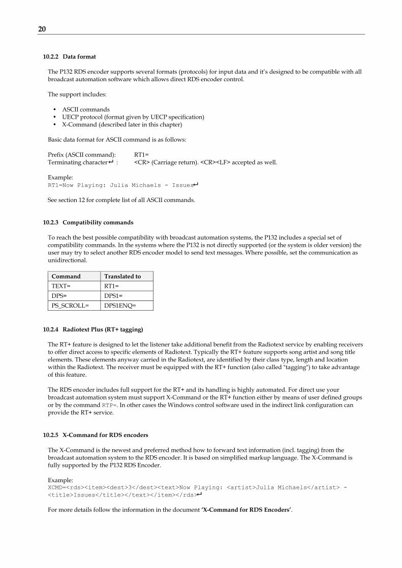
10.2.2 Data format The P132 RDS encoder supports several formats (protocols) for input data and it’s designed to be compatible with all broadcast automation software which allows direct RDS encoder control. The support includes:
• ASCII commands • UECP protocol (format given by UECP specification) • X-Command (described later in this chapter)
Basic data format for ASCII command is as follows: Prefix (ASCII command): RT1= Terminating character : <CR> (Carriage return). <CR><LF> accepted as well. Example: RT1=Now Playing: Julia Michaels - Issues
See section 12 for complete list of all ASCII commands.
10.2.3 Compatibility commands
To reach the best possible compatibility with broadcast automation systems, the P132 includes a special set of compatibility commands. In the systems where the P132 is not directly supported (or the system is older version) the user may try to select another RDS encoder model to send text messages. Where possible, set the communication as unidirectional.
Command Translated to
TEXT= RT1=
DPS= DPS1=
PS_SCROLL= DPS1ENQ=
10.2.4 Radiotext Plus (RT+ tagging) The RT+ feature is designed to let the listener take additional benefit from the Radiotext service by enabling receivers to offer direct access to specific elements of Radiotext. Typically the RT+ feature supports song artist and song title elements. These elements anyway carried in the Radiotext, are identified by their class type, length and location within the Radiotext. The receiver must be equipped with the RT+ function (also called "tagging") to take advantage of this feature. The RDS encoder includes full support for the RT+ and its handling is highly automated. For direct use your broadcast automation system must support X-Command or the RT+ function either by means of user defined groups or by the command RTP=. In other cases the Windows control software used in the indirect link configuration can provide the RT+ service.
10.2.5 X-Command for RDS encoders The X-Command is the newest and preferred method how to forward text information (incl. tagging) from the broadcast automation system to the RDS encoder. It is based on simplified markup language. The X-Command is fully supported by the P132 RDS Encoder. Example: XCMD=<rds><item><dest>3</dest><text>Now Playing: <artist>Julia Michaels</artist> -
<title>Issues</title></text></item></rds>
For more details follow the information in the document ‘X-Command for RDS Encoders’.
21
11 Communication Ports
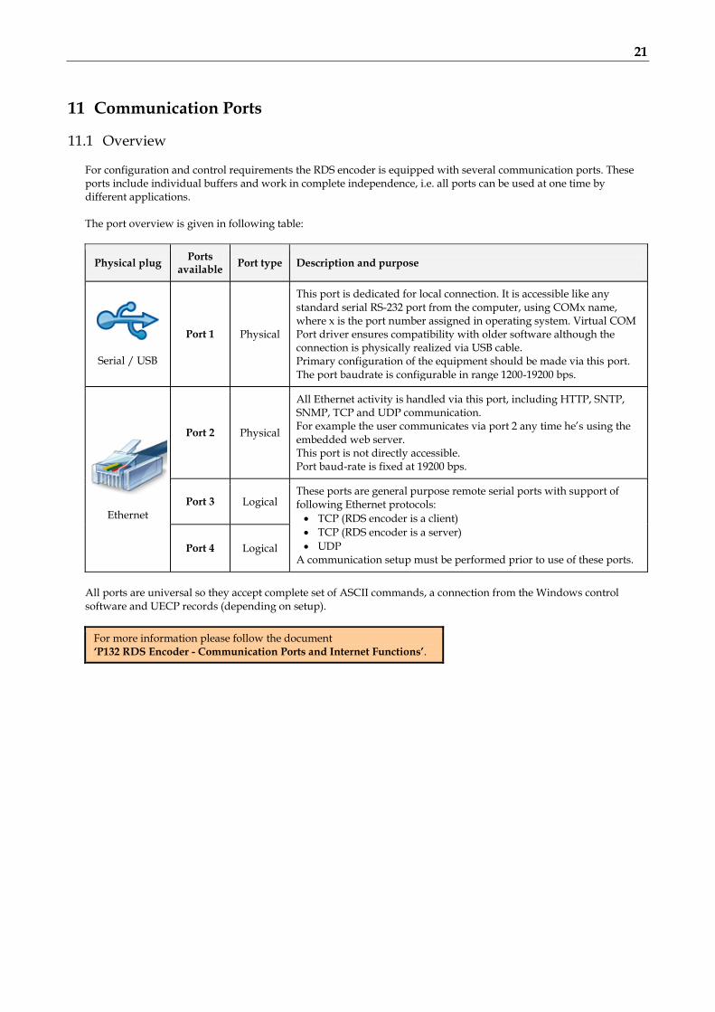
11.1 Overview For configuration and control requirements the RDS encoder is equipped with several communication ports. These ports include individual buffers and work in complete independence, i.e. all ports can be used at one time by different applications. The port overview is given in following table:
Physical plug Ports
available Port type Description and purpose
Serial / USB
Port 1 Physical
This port is dedicated for local connection. It is accessible like any standard serial RS-232 port from the computer, using COMx name, where x is the port number assigned in operating system. Virtual COM Port driver ensures compatibility with older software although the connection is physically realized via USB cable. Primary configuration of the equipment should be made via this port. The port baudrate is configurable in range 1200-19200 bps.
Ethernet
Port 2 Physical
All Ethernet activity is handled via this port, including HTTP, SNTP, SNMP, TCP and UDP communication. For example the user communicates via port 2 any time he’s using the embedded web server. This port is not directly accessible. Port baud-rate is fixed at 19200 bps.
Port 3 Logical These ports are general purpose remote serial ports with support of following Ethernet protocols:
TCP (RDS encoder is a client)
TCP (RDS encoder is a server)
UDP A communication setup must be performed prior to use of these ports.
Port 4 Logical
All ports are universal so they accept complete set of ASCII commands, a connection from the Windows control software and UECP records (depending on setup).
For more information please follow the document ‘P132 RDS Encoder - Communication Ports and Internet Functions’.

22
11.2 Working with a Terminal Application This section explains how to make the settings above from a terminal application (and also from embedded web-server). All RDS encoder’s settings and configuration incl. text messages etc. can be made from a terminal using a set of ASCII commands. (Any Windows GUI based application effectively does the same; it translates the user’s data into the ASCII commands.) 1. In the case of USB connection install the USB driver now.
2. Make sure the RDS encoder is connected and powered, and all connectors are seated completely.
3. On the PC, run an application or program emulating or possessing an ASCII terminal. For example Windows HyperTerminal in Windows XP presents all the characteristics to easily communicate in ASCII mode with the RDS encoder. Note: Latest Windows versions unfortunately no longer contain terminal application. That needs to be installed additionally from public resources. Suitable replacement for the Windows HyperTerminal is the PuTTY client that is available for free download at http://www.putty.org.
4. For USB connection configure the communication parameters as follows:
Transmission speed 2400 bps (default, see note)
Data bits 8
Parity None
Stop bits 1
Flow control None
Note: If the RDS encoder was previously in use, there may remain any speed from 1200, 2400, 4800, 9600 or 19200 bps. Actual speed is showed on the encoder’s LCD display or can be retrieved via internal website.
5. For TCP connection, fill the encoder’s IP address and network port number on which the encoder listens for the connection. The RDS encoder must be configured before using the TCP connection.
Once configured, the terminal can be used. To check if the hardware and logic configuration work as planned, type for example HELP and press <Enter> to display the list of all commands. If no or unknown characters are displayed on the screen, try again a second time, otherwise, check the following points:
RDS encoder turned on?
Cable used (does the LED1 indicate incoming characters?)
Configuration of the terminal application To display the commands entered at the keyboard on the screen, type the command ECHO=1 followed by <Enter>. If all characters written are displayed twice, type ECHO=0 and press <Enter>. To store this parameter into a non-volatile EEPROM memory, type *ECHO and press <Enter>. To display actual parameter value, type ECHO and press <Enter>. Now you made first steps with the RDS encoder command interpreter.

23
11.3 Command Interpreter The RDS encoder command interpreter meets the following rules: Any instruction sent to the RDS encoder must be validated by <Enter>. Before validating you may correct the characters by pressing <Backspace>. There are several methods of use for the commands: Query or command without argument, ex. HELP
Shows the parameter value or performs the operation. Command with argument, ex. ECHO=1
Assigns the value to the parameter. Memory store command, ex. *ALL
Stores the parameter value(s) into the non-volatile EEPROM memory. Memory store command with argument, ex. *MSG01=
Assigns the value to the parameter and stores it immediately into the non-volatile EEPROM memory. Not all methods are available for all commands, see Command Summary section. Depending on the command processing success, several characters (followed by two pairs of carriage return and line feed characters) can be returned by the RDS encoder:
+ Command processed successfully
! Unknown command
- Invalid argument
/ Command processed partially
The command interpreter is not case sensitive. But it’s recommended to write all commands in UPPER CASE to maintain backward compatibility with older firmware versions. If you wish to retain change of any parameter value during power off, don’t forget to store it into EEPROM memory!
Windows Hyperterminal control.

24
11.4 Additional Information
This additional information provides all details required for implementation of the P132 protocol into your application (broadcast automation system, messaging system, TMC data source etc.). Please see also the Annex 1 - Communication Protocol Implementation Flowcharts. Some source code examples are provided on the website.
11.4.1 Unidirectional or bidirectional – What is the difference? The P132 supports both unidirectional and bidirectional communication modes. Nothing is required to be set, the mode of operation results only from the method of communication.
Unidirectional (backward channel from the RDS encoder is not present or the data from this channel is ignored)
Very simple to implement Low cost data link No direct feedback from the unit
Bidirectional (both channels are used)
Reliable remote control Backward channel may be hard to realize in some cases Unsuitable for larger networks
11.4.2 Command synchronization
Unidirectional communication: If sending more commands in sequence, the execution times must be taken into consideration. In other case some commands may be discarded after internal buffer filling.
Command Execution time
PS=, TPS=, DPSx= up to 400 ms
G= up to 200 ms
*ALL 200 ms
*EON, *DPSx, *MSGxx= 50 ms
Other store commands, SEN= 10 ms
All other commands 0 ms (typ.)
The times result from the EEPROM write cycle duration or from the requirement of internal synchronization with RDS data group order. Most of commands require no perceptible delay due to internal RX line buffering.
TX P S = P R O 8 8 ← (execution time) (next command may follow)
Legend: TX – data sent to the RDS encoder, ← - CR (char. 13, <Enter>)

25
Bidirectional communication:
Next command can be sent after receiving confirm sequence from previous command. This ensures right timing and optimal channel usage in all cases. There is no need to consider any timing or delays.
TX P S = P R O 8 8 ← (next command may follow)
RX (ECHO=1) P S = P R O 8 8 (exec. time) ← ↓ + ← ↓ ← ↓
RX (ECHO=0) (exec. time) ← ↓ + ← ↓ ← ↓
TX P S ← (next command may follow)
RX (ECHO=1) P S ← ↓ P R O 8 8 ← ↓ + ← ↓ ← ↓
RX (ECHO=0) ← ↓ P R O 8 8 ← ↓ + ← ↓ ← ↓
TX * P S ← (next command may follow)
RX (ECHO=1) * P S (exec. time) ← ↓ + ← ↓ ← ↓
RX (ECHO=0) (exec. time) ← ↓ + ← ↓ ← ↓
Legend: TX – data sent to the RDS encoder, RX – data read from the RDS encoder, ← - CR (char. 13), ↓ - LF (char. 10)
11.4.3 Useful notes ASCII char. 9 (TAB) is converted to char. 32 (space). In addition to the <Enter> (char. 13, CR) used for command validating, character 26 (EOF) can be used. This
allows to insert the validating character on platforms where char. 13 (CR) is not accepted. The command interpreter ignores other characters in ASCII range 0-31. Space characters (char. 32) are ignored if typed behind validating character on a new line. In this case, the space
characters may be used to realize a delay between two commands. The port time-out is 2 minutes. If no character is received during this time, the command line on that port is
internally cleared. For automated control (machine to machine), if getting a response from the encoder, the block of echoed
characters should be entirely ignored. That is, after starting to send the command, the control application should ignore all characters received until the application receives first CR+LF from the encoder. This ensures receiving of correct data regardless of the echo state.

26
12 List of Commands
12.1 Command Summary
Basic: AF AF= *AF *AF= Alternative Frequencies AFCH AFCH= *AFCH Alternative Frequency Channels DI DI= *DI Decoder Identification DPS1 DPS1= *DPS1 Dynamic PS 1 DPS1ENQ= Dynamic PS 1 Enqueue DPS2 DPS2= *DPS2 Dynamic PS 2 DPS1EN DPS1EN= *DPS1EN Dynamic PS 1 Enable DPS2EN DPS2EN= *DPS2EN Dynamic PS 2 Enable DPS1MOD DPS1MOD= *DPS1MOD Dynamic PS 1 Mode DPS2MOD DPS2MOD= *DPS2MOD Dynamic PS 2 Mode DPS1REP DPS1REP= *DPS1REP Dynamic PS 1 Number of Repeating DPS2REP DPS2REP= *DPS2REP Dynamic PS 2 Number of Repeating DTTMOUT DTTMOUT= *DTTMOUT Default Text Timeout EQTEXT1 EQTEXT1= *EQTEXT1 Equal Text 1 LABPER LABPER= *LABPER Label Period MS MS= *MS Music/Speech PI PI= *PI Program Identification PS PS= *PS Program Service name PTY PTY= *PTY Program Type number PTYN PTYN= *PTYN Program Type Name PTYNEN PTYNEN= *PTYNEN PTYN Enable RT1 RT1= *RT1 Radiotext 1 RT1EN RT1EN= *RT1EN RT1 Enable RT2 RT2= *RT2 Radiotext 2 RT2EN RT2EN= *RT2EN RT2 Enable RTPER RTPER= *RTPER Radiotext Switching Period RTTYPE RTTYPE= *RTTYPE Radiotext Type RSTDPS RSTDPS= *RSTDPS Restart Dynamic PS SCRLSPD SCRLSPD= *SCRLSPD Scrolling PS Speed SPSPER SPSPER= *SPSPER Static PS Period TA TA= *TA Traffic Announcement TATMOUT TATMOUT= *TATMOUT TA Timeout TP TP= *TP Traffic Program TPS TPS= *TPS Traffic PS INIT Initialization *ALL Store All HELP Help
EON: EONxAF EONxAF= EON x Frequencies EONxAFCH EONxAFCH= EON x Frequency channels EONxEN EONxEN= EON x Enable EONxPI EONxPI= EON x Program Identification EONxPS EONxPS= EON x Program Service name EONxPSN EONxPSN= EON x Program Service Number EONxPTY EONxPTY= EON x Program Type number EONxTA EONxTA= EON x Traffic Announcement EONxTP EONxTP= EON x Traffic Program *EON Store all EON data into EEPROM
x is in range 1-4
Note: Almost all commands have their equivalent in the Windows control software, accessible through its GUI.

27
Messages: MSGxx *MSGxx= Text Message MSGxxD *MSGxxD= Message Destination MSGLIST List of Messages DPS2MSG DPS2MSG= *DPS2MSG Dynamic PS 2 Message Number RT2MSG RT2MSG= *RT2MSG Radiotext 2 Message Number
xx is in decimal range 01-99
Scheduling: SLIST List of Scheduling Items SxxC *SxxC= Scheduling Item Command SxxD *SxxD= Scheduling Item Days SxxP *SxxP= Scheduling Item PTY SxxT *SxxT= Scheduling Item Times SEN SEN= *SEN Scheduling Enable
xx is in decimal range 01-48 System: COMSPD COMSPD= *COMSPD Port 1 Speed CT CT= *CT Clock Time and Date DATE DATE= Date ECHO ECHO= *ECHO Terminal Echo EXTSYNC EXTSYNC= *EXTSYNC External Pilot Synchronization IPA Actual IP Address LEVEL LEVEL= *LEVEL RDS Signal Level LTO LTO= *LTO Local Time Offset MJD MJD= Modified Julian Day PHASE PHASE= *PHASE RDS Signal Phase PILOT Pilot Tone Present PSNMAIN PSNMAIN= *PSNMAIN PSN of Main Program RDSGEN RDSGEN= *RDSGEN RDS Generator RESET Reset SETCTO SETCTO= *SETCTO= Connection Timeout SETFEAT SETFEAT= *SETFEAT= Special Features SETLAN SETLAN= *SETLAN= Ethernet Setup SETPORT3 SETPORT3= *SETPORT3= Port 3 Setup SETPORT4 SETPORT4= *SETPORT4= Port 4 Setup SETSNMP SETSNMP= *SETSNMP= SNMP Enable SPEED SPEED= *SPEED Port 1 Speed STATUS RDS Encoder Status TIME TIME= Time VER Firmware Version

28
Advanced: ADR *ADR= Encoder Address List CC *CC= Conditional Command EAS= Send EAS Text Message EASTIME= Set EAS Timer ECC ECC= *ECC Extended Country Code ECCEN ECCEN= *ECCEN ECC and LIC Enable G= Group GRPSEQ GRPSEQ= *GRPSEQ Group Sequence LIC LIC= *LIC Language Identification Code PAC y,zz PAC y,zz= *PAC Port Access Control PROGRAM PROGRAM= *PROGRAM Program Set Selection PSW PS Window Rabbbb,cc Read Memory READWEB READWEB= *READWEB Reading of Internet Content RTP RTP= Radiotext Plus Tagging Data RTPRUN RTPRUN= Radiotext Plus Running Bit SETIPR SETIPR= *SETIPR= IP Registration URL SETSPY= Set RDS Monitoring Counter SHORTRT SHORTRT= *SHORTRT Short Radiotext SITE *SITE= Site Address List UDG1 UDG1= *UDG1 User Defined Groups 1 UDG2 UDG2= *UDG2 User Defined Groups 2 UECP UECP= *UECP UECP Enable XCMD= X-Command for RDS encoders
x is in range 1 to 2 y is in range 0 to 4 zz is in range 00 to FF (hex)

29
12.2 Basic Commands
AF Alternative Frequencies (87.6-107.9), A, B, (1-8)
Actual list of alternative frequencies in MHz representation in range of 87.6-107.9 MHz. Up to 25 items are allowed in the list. In addition this command switches between AF method A and B and allows working with different AF lists for the method B. For more details about the method B follow the section 7. From factory the AF method is set to A.
AF=103.5,98.0
AF
*AF
*AF=1
AF=87.5
AF=108.0
Sets the alternative frequencies to 103.5 and 98.0 MHz (method A) Shows actual AF list. Returns "B" if method B is active. Stores the AF list into EEPROM (default space for method A) Stores the AF list into EEPROM (to a space used by method B) Not allowed (87.5 MHz not defined in RDS standard) Not allowed (108.0 MHz not defined in RDS standard)
AFCH Alternative Frequency Channels H (01-CC)
Actual list of alternative frequency channels in hexadecimal representation in range of 01-CC (87.6-107.9 MHz). Up to 25 items are allowed in the list.
AFCH=01,3B
AFCH=00
AFCH=CD
Sets the alternative frequencies to 87.6 and 93.4 MHz Not allowed (87.5 MHz not defined by RDS standard) Not allowed (108.0 MHz not defined by RDS standard)
DI Decoder Identification (0-15)
Identification of the decoder to be used by the receiver.
DI=1
DI=0
Standard transmission - stereo. Standard transmission - automatic stereo/mono set depending on pilot tone presence.
DPS1 Dynamic PS 1
Up to 255 characters long text message to be displayed on receiver instead of static PS name. Primarily used for song titles streaming etc.
DPS1=Hello World
DPS1=
Sets the DPS1 text Clears the DPS1
DPS1EN Dynamic PS 1 Enable (0, 1)
Enables (1) or disables (0) the Dynamic PS 1 text.
DPS1EN=1 Enables the DPS1 text.
DPS2EN Dynamic PS 2 Enable (0, 1)
Enables (1) or disables (0) the Dynamic PS 2 text.
DPS1ENQ Dynamic PS 1 Enqueue
Advanced version of the DPS1 command. Places the text to a one level deep queue. New text will not be displayed on the receiver until old text reaches its end. Applies only to text length <128 characters.
DPS1ENQ=Hello World Sets the following DPS1 text
DPS2 Dynamic PS 2
Up to 255 characters long text message to be displayed on receiver instead of static PS name. Alternatively used in conjunction with Messages Commands.
DPS2=Hello World
DPS2=
Sets the DPS2 text Clears the DPS2
DPS1MOD Dynamic PS 1 Mode (0-3)
Display mode for the DPS1 text. 0 - Scrolling by 8 characters 1 - Scrolling by 1 character 2 - Word alignment scrolling 3 - Scrolling by 1 character, text separated by spaces at begin and end Note: In mode 3 the maximum text length is limited to 240 characters.
DPS1MOD=3

30
DPS2MOD Dynamic PS 2 Mode (0-3)
Display mode for the DPS2 text. 0 - Scrolling by 8 characters 1 - Scrolling by 1 character 2 - Word alignment scrolling 3 - Scrolling by 1 character, text separated by spaces at begin and end Note: In mode 3 the maximum text length is limited to 240 characters.
DPS2MOD=3
DPS1REP Dynamic PS 1 Number of Repeating (0-127)[,CLR]
Specifies number of repeating for the DPS1 text message. Optionally the DPS1 text is then cleared. Without the optional CLR parameter specified the command has effect only if DPS2 is enabled. Number of repeating = number of transmissions - 1.
DPS1REP=1
DPS1REP=2,CLR
DPS2REP Dynamic PS 2 Number of Repeating (0-255)
Specifies number of repeating for the DPS2 text message. Has effect only if DPS1 is enabled or if DPS2MSG value is AUTO. Number of repeating = number of transmissions - 1.
DPS2REP=0
DTTMOUT Default Text Timeout (0-254)
Specifies a timeout in minutes for Radiotext 1. If no RT1 has been received during the period, the RT1 text is replaced by default text. If RT+ service is active, the RT+ running bit is cleared.
Default text means the RT1 text that is stored in EEPROM memory using *RT1. Following exceptions apply: For Program 1, if Message 91 contains a valid X-Command, it is launched on the Default Text timeout event. For Program 2, if Message 92 contains a valid X-Command, it is launched on the Default Text timeout event. 1-254 – Timeout in minutes. 0 – Function disabled.
DTTMOUT=10
EQTEXT1 Equal Text 1 (0, 1)
If set to 1, any update of Radiotext 1 via any port updates also Dynamic PS1 and vice versa. Applies also to UECP control. Has no effect for X-Command.
EQTEXT1=1
DPS1=Hello World
RT1
LABPER Label Period (0-255)
Label Period used in DPS Mode 0 and 2. Increasing the value by 1 increases the period by approx. 0.54 seconds (exact value depends on Group Sequence).
LABPER=4 Each label is displayed for about 2 seconds.
MS Music/Speech (0, 1)
Music/Speech switch.
MS=0
MS=1
Speech program Music program
PI Program Identification H (1000-FFFF)
Identification code of the radio station. Always contains four hexadecimal digits.
PI=20FE
PI=0F55
OK Not allowed (0 as first digit)
PS Program Service name
Static name of radio station that is displayed on receiver. Max. 8 characters long. The PS= command requires additional processing time of up to 400 ms for internal synchronization with RDS group order.
PS=KISS FM

31
PTY Program Type number (0-31)
An identification number to be transmitted with each program item, intended to specify the current Program Type within 31 possibilities. Program type codes (Europe): 0 - (none) 1 - News 2 - Affairs 3 - Info 4 - Sport 5 - Education 6 - Drama 7 - Cultures 8 - Science 9 - Varied Speech 10 - Pop Music 11 - Rock Music 12 - Easy Music 13 - Light Classics Music 14 - Serious Classics 15 - Other Music Program type codes (US RBDS): 0 - (none) 1 - News 2 - Information 3 - Sports 4 - Talk 5 - Rock 6 - Classic Rock 7 - Adult Hits 8 - Soft Rock 9 - Top 40 10 - Country 11 - Oldies 12 - Soft 13 - Nostalgia 14 - Jazz 15 - Classical
16 - Weather 17 - Finance 18 - Children 19 - Social Affairs 20 - Religion 21 - Phone In 22 - Travel 23 - Leisure 24 - Jazz Music 25 - Country Music 26 - National Music 27 - Oldies Music 28 - Folk Music 29 - Documentary 30 - Alarm Test 31 - Alarm 16 - Rhythm and Blues 17 - Soft Rhythm and Blues 18 - Foreign Language 19 - Religious Music 20 - Religious Talk 21 - Personality 22 - Public 23 - Leisure 24 - College 25 - (unassigned) 26 - (unassigned) 27 - (unassigned) 28 - (unassigned) 29 - Weather 30 - Emergency Test 31 - Emergency
PTY=10 Sets the Pop Music Program Type (EU)
PTYN Program Type Name
Allows further description of the current Program Type, for example, when using the PTY code 4: SPORT, a PTYN of "Football" may be indicated to give more detail about that program.
PTYN=Football
PTYNEN PTYN Enable (0, 1)
Enables (1) or disables (0) the PTYN service.
PTYNEN=1 Enables the PTYN service
RT1 Radiotext 1
Up to 64 characters long text message to be displayed on receiver in Radiotext format. Primarily used for song titles streaming, commercials etc.
RT1=Hello World
RT1EN RT1 Enable (0, 1)
Enables (1) or disables (0) the Radiotext 1.
RT1EN=1 Enables the RT1

32
RT2 Radiotext 2
Up to 64 characters long text message to be displayed on receiver in Radiotext format. Alternatively used in conjunction with Messages Commands.
RT2=Hello World
RT2EN RT2 Enable (0, 1)
Enables (1) or disables (0) the Radiotext 2.
RT2EN=1 Enables the RT2
RTPER Radiotext Switching Period (0-255)
Specifies the time in minutes between two switching of the Radiotext. The switching can occur between RT1 and RT2 or between messages specified for RT2 (command RT2MSG=AUTO).
RTPER=10
RTPER=0
Sets the period to 10 min. Sets the period to 0.5 min.
RTTYPE Radiotext Type (0-3)
Specifies Radiotext type for RT1 and RT2 0 - A/A. Any Radiotext is always the same type. 1 - A/B. RT1 is always type A, RT2 is always type B. 2 - Automatic. Any change/update of the Radiotext causes the A/B flag to toggle. Default option. Required for proper RT+ function. 3 – Same as 2 but also overrides UECP A/B flag control. If the receiver detects a change in the A/B flag, then the whole Radiotext display is usually cleared and the newly received Radiotext message segments are written into the display. If the receiver detects no change in the A/B flag, then the received text segments or characters are written into the existing displayed message. Some receivers have two memory spaces for the Radiotext, one for type A and one for type B. Then they display both messages consecutively in the loop.
RTTYPE=2
RSTDPS Restart Dynamic PS (0, 1)
1 – When the Dynamic PS text is changed and no Dynamic PS is running, it will start immediately. 0 – The SPSPER command drives the Dynamic PS start regardless of the fact that the Dynamic PS text was changed. Changing a Dynamic PS text (1 or 2) that is actually running will always cause its restart. This rule does not apply to the DPS1ENQ command.
RSTDPS=1
SCRLSPD Scrolling PS Speed (0, 1)
Sets high (1) or low (0) speed of scrolling PS transmission. Although setting high speed gives the result looking better, remember that on some receivers or under bad reception conditions the text may be unreadable. The reason is absolutely outside the RDS encoder and comes out from the fact that scrolling PS has never been included in RDS standard. Due to this the high speed is not recommended.
SCRLSPD=1
SPSPER Static PS Period (0-255)
Specifies the time between two repeats of the Dynamic PS text. Static PS (PS/TPS) is displayed during this time. Increasing the value by 1 increases the period by approx. 2.7 seconds (exact value depends on Group Sequence). If value 255 is set, the Dynamic PS will be displayed only once if changed. RSTDPS parameter must be set to 1 in this case. If both DPS1 and DPS2 are enabled, the SPSPER cannot be zero (0).
SPSPER=4 Sets the period duration to about 11 seconds.

33
TA Traffic Announcement (0, 1)
Indicates instantaneous presence (1) of traffic information during broadcasting. When this value is set to 1 by external TA switch, the value specified by TA command has no effect. When this value is set to 1 by TA command, the value set by external TA switch has no effect. Switching the PROGRAM causes clearing of the TA flag. Note: In some cases the RDS encoder drives the TP and TA flags automatically, especially if EON feature is enabled. This ensures that these flags are set correctly under all conditions.
TA=1
TATMOUT TA Timeout (0-127) [+128]
Specifies a maximum duration in minutes during which the TA parameter can remain active. 0 - Disables the TA timeout feature. External TA switch is level controlled (logic 0 means TA=1). 1-127 - Specifies a maximum duration in minutes during which the TA parameter can remain active (1).
Then the TA flag is set back to zero (0). External TA switch is activated by falling edge. Rising edge is ignored.
+128 - Adding 128 results in the same behavior as above except that also rising edge can set the TA back to zero (if detected before the timeout).
Note: The timeout is synchronized with real time clock minutes, i.e. the timeout event can only occur in whole minutes. Note: The TATMOUT command doesn’t affect the EON1TA switching. The External EON1TA switch can be level controlled only. Note: If TP=0, the TA Timeout is always set to 0.
TATMOUT=0
TATMOUT=2
TATMOUT=130
No timeout. Logic 0 on the TA switch input results in TA=1, logic 1 or no connection results in TA=0. TA is activated (set to 1) on falling edge on the TA switch input (logic 1 to logic 0 transition). After 2 minutes the TA is set back to 0. Rising edge is ignored so may occur anytime. TA is activated on falling edge on the TA switch input. The TA is set back to 0 on either the rising edge or after 2 minutes timeout, depending on which event occurs first.
TP Traffic Program (0, 1)
This is a flag to indicate that the tuned program carries traffic announcements. The TP flag must only be set on programs that dynamically switch on the TA identification during traffic announcements. The signal shall be taken into account during automatic search tuning. Note: In some cases the RDS encoder drives the TP and TA flags automatically, mainly if EON feature is enabled. This ensures that these flags are set correctly under all conditions.
TP=1
TPS Traffic PS
Static text displayed on receiver during traffic announcements. Max. 8 characters long. The TPS= command requires additional processing time of up to 400 ms for internal synchronisation with RDS group order.
TPS=TRAFFIC
TPS=
Disables the Traffic PS

34
INIT Initialization
Sets most parameters and services in actually selected Program to their default values. Does not clear Messages and Scheduling items. Does not clear port and network settings. Apply for example if new blank EEPROM is placed on the board or if the RDS encoder was previously used for another station.
INIT
*CC=
PROGRAM=6
INIT
*ALL
PROGRAM=5
INIT
*ALL
PROGRAM=4
INIT
*ALL
PROGRAM=3
INIT
*ALL
PROGRAM=2
INIT
*ALL
PROGRAM=1
INIT
*ALL
TIME=HH:MM
DATE=DD.MM.YY
Initialize the program set that is currently selected. Complete initialization procedure. Replace the HH:MM with actual time and the DD.MM.YY with actual date. Note: This initialization sequence must always be applied if new blank EEPROM is placed on the board in production process. Alternatively use the Windows control software: Device Setup – Special – Initialize.
ALL Store All
Stores all settings into the non-volatile EEPROM memory.
*ALL
HELP Help
Shows all commands available.
HELP
35
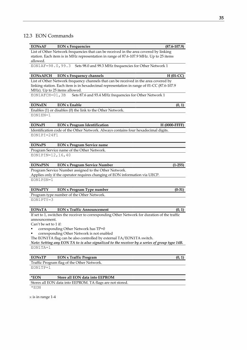
12.3 EON Commands
EONxAF EON x Frequencies (87.6-107.9)
List of Other Network frequencies that can be received in the area covered by linking station. Each item is in MHz representation in range of 87.6-107.9 MHz. Up to 25 items allowed.
EON1AF=98.0,99.3 Sets 98.0 and 99.3 MHz frequencies for Other Network 1
EONxAFCH EON x Frequency channels H (01-CC)
List of Other Network frequency channels that can be received in the area covered by linking station. Each item is in hexadecimal representation in range of 01-CC (87.6-107.9 MHz). Up to 25 items allowed.
EON1AFCH=01,3B Sets 87.6 and 93.4 MHz frequencies for Other Network 1
EONxEN EON x Enable (0, 1)
Enables (1) or disables (0) the link to the Other Network.
EON1EN=1
EONxPI EON x Program Identification H (0000-FFFF)
Identification code of the Other Network. Always contains four hexadecimal digits.
EON1PI=24F1
EONxPS EON x Program Service name
Program Service name of the Other Network.
EON1PIN=12,16,40
EONxPSN EON x Program Service Number (1-255)
Program Service Number assigned to the Other Network. Applies only if the operator requires changing of EON information via UECP.
EON1PSN=1
EONxPTY EON x Program Type number (0-31)
Program type number of the Other Network.
EON1PTY=3
EONxTA EON x Traffic Announcement (0, 1)
If set to 1, switches the receiver to corresponding Other Network for duration of the traffic announcement. Can’t be set to 1 if: corresponding Other Network has TP=0 corresponding Other Network is not enabled The EON1TA flag can be also controlled by external TA/EON1TA switch. Note: Setting any EON TA to is also signalized to the receiver by a series of group type 14B.
EON1TA=1
EONxTP EON x Traffic Program (0, 1)
Traffic Program flag of the Other Network.
EON1TP=1
*EON Store all EON data into EEPROM
Stores all EON data into EEPROM. TA flags are not stored.
*EON
x is in range 1-4

36
12.4 Messages Commands
These commands are provided for working with the bank of fixed text messages that is useful especially for offline operation of the RDS encoder or in conjunction with the scheduling feature. Using these commands you may enter the text messages and assign them to Radiotext, Dynamic PS or X-Command.
MSGxx Text Message
Specifies the fixed message text. Since there is a place for 99 messages in the memory, the number xx must be in range 01-99. For Program 1, if Message 91 contains a valid X-Command, it is launched on the Default Text timeout event. For Program 2, if Message 92 contains a valid X-Command, it is launched on the Default Text timeout event.
*MSG01=Hello World
MSGxxD Message Destination (0-3)
Specifies the destination of the message used for automatic message switching. The number xx must be in range 01-99. 0 - Message not used for automatic switching 1 - DPS2 2 - RT2 3 - DPS2 and RT2 4 – X-Command Timer
*MSG01D=1
MSGLIST List of Messages
Shows all messages present in the memory and its destination.
MSGLIST
DPS2MSG Dynamic PS 2 Message Number (0-99, AUTO)
0 - Default DPS2 text specified by DPS2 command or last DPS2MSG command is selected. 1-99 - The message of the number is selected for the DPS2. AUTO - Messages are selected automatically in ascending order. Only messages chosen by the MSGxxD
command are selected.
DPS2MSG=AUTO
RT2MSG Radiotext 2 Message Number (0-99, AUTO)
0 - Default RT2 text specified by RT2 command or last RT2MSG command is selected. 1-99 - The message of the number is selected for the RT2. AUTO - Messages are selected automatically in ascending order. Only messages chosen by the MSGxxD
command are selected.
RT2MSG=1
xx is in decimal range 01-99

37
12.5 Scheduling Commands
SLIST List of Scheduling Items
Shows all scheduling items. Items with no day specified are not showed. Each item is represented by the following order: Item No., Days, Times, Command, PTY.
SLIST
SEN Scheduling Enable (0, 1)
Enables (1)/disables (0) the scheduling feature.
SEN=1 Enables the scheduling feature.
SxxC Scheduling Item Command
Specifies the command to execute. Max. command length is 35 characters. Only commands from the second column of the Command Summary are allowed.
*S01C=RDSGEN=0
*S03C=RT2MSG=12
*S04C=
Clears (disables) the command for the item 04.
*S05C=XCMD=<rds><msg>40</msg></rds> Schedules the item 05 to process X-Command stored in Message 40
SxxD Scheduling Item Days (1-7)
Specifies the days for which the item is valid. Monday = 1.
*S03D=12367
SxxP Scheduling Item PTY (0-31)
Allows including optional Program Type information so that the Command may be used for another RDS service change.
*S03P=15
*S04P=
Sets the PTY to 15 (Other M) Clears (disables) the PTY option for the item 04.
SxxT Scheduling Item Times
Specifies the times in 24-hours HH:MM format at which the item command is executed. Wildcard XX can be used instead of hour number meaning that the item will be executed each hour in specified minute. If more items are scheduled for the same time, all these items are executed in ascending order. Up to 12 times allowed for each item.
*S03T=XX:30,12:00
xx is in decimal range 01-48

38
12.6 System Commands
COMSPD Port 1 Speed (0-4)
Specifies the port 1 speed (baudrate). 0 - 1200 bps 1 - 2400 bps (default) 2 - 4800 bps 3 - 9600 bps 4 - 19200 bps This command has the same effect as SPEED but the format of input is different.
COMSPD=1
CT Clock Time and Date (0, 1)
Enables (1) or disables (0) time and date transmission in CT format.
CT=1
DATE Date
Specifies the actual date in DD.MM.YY format.
DATE=30.11.05 30th of November 2005
ECHO Terminal Echo (0, 1)
Determines if the RDS encoder sends an echo (1) of each character or not (0), that it receives via the port.
ECHO=1
EXTSYNC External Pilot Synchronization (0, 1)
0 - Forced internal clock source (for mono transmission) 1 - Automatic external synchronization if pilot tone is present
EXTSYNC=1
IPA Actual IP Address
This command is described in the document ‘P132 RDS Encoders – Communication Ports and Internet
Functions’.
LEVEL RDS Signal Level (0-255)
Sets the RDS signal level, directly affects the injection of the RDS signal into the FM transmitter. 0 = minimum level, 255=maximum level.
LEVEL=120
LTO Local Time Offset ±(0-24)
Specifies the offset between the local time and the universal time (UTC). Expressed in multiples of half-hours.
LTO=+2
MJD Modified Julian Day H (000000-FFFFFF)
Day, Month and Year coded as Modified Julian Day. To find D, M and Y from MJD:
Y' = int [ (MJD - 15 078,2) / 365,25 ] M' = int { [ MJD - 14 956,1 - int (Y' × 365,25) ] / 30,6001 } D = MJD - 14 956 - int ( Y' × 365,25 ) - int ( M' × 30,6001 ) If M' = 14 or M' = 15, then K = 1; else K = 0 Y = Y' + K M = M' - 1 - K × 12
To find MJD from D, M and Y: If M = 1 or M = 2, then L = 1; else L = 0 MJD = 14 956 + D + int [ (Y - L) × 365,25] + int [ (M + 1 + L × 12) × 30,6001 ]
Y', M', K, L - intermediate variables.
MJD=00D7CD 18th of February 2010

39
PHASE RDS Signal Phase (0-18)
Fixes the relative phase shift between the pilot tone and the RDS signal. Changing the value by one results in 9.5 degrees phase shift change. The value serves only as a scale, it may not provide real phase shift value.
PHASE=8
PILOT Pilot Tone Present
Indicates if pilot tone is present (1) or not (0).
PILOT
PSNMAIN PSN of Main Program (1-254)
Specifies optional PSN (Program Service Number) for current Program set. This option has effect for UECP control only.
PSNMAIN=1
RDSGEN RDS Generator (0, 1)
Disables (0) or enables (1) the RDS subcarrier generator. Does not affect any other functions.
RDSGEN=0
RESET Reset
Provokes a hardware reset of the RDS encoder and is equivalent to an "off-on" cycle of the RDS encoder.
RESET
SETCTO Connection Timeout
This command is described in the document ‘P132 RDS Encoders – Comm. Ports and Internet Functions’.
SETFEAT Special Features H (0000–3FFF)
This is a 16-bit Hex value bitmap which holds enabling bits for special RDS encoder features: Bit 0: Dynamic group sequence. If enabled (1), temporarily doubles the 2A group rate after the RT is changed. Bit 1: RT+ group type 11A/13A. Selects group type for RT+ service. Applies to RTP and XCMD commands. Bit 2: reserved, set as 0. Bit 3: X-Command Timer Message – resume (0) or reset (1). Bit 4: Enables scrolling of long words for Dynamic PS Mode 2 (Word parsing mode). Bit 5: Chooses between left alignment (0) and centering (1) for Dynamic PS Mode 2 (Word parsing mode). Bits 6 to 15: reserved, set as 0. Note: The ‘*’ prefix may be omitted for this command.
SETFEAT=0001 Enables dynamic group sequence, sets group type 11A for RT+ SETFEAT=0003
SETFEAT=0000
Enables dynamic group sequence, sets group type 13A for RT+ Factory default value
SETLAN Ethernet Setup
This command is described in the document ‘P132 RDS Encoders – Comm. Ports and Internet Functions’.
SETPORTx Port 3/4 Setup
This command is described in the document ‘P132 RDS Encoders – Comm. Ports and Internet Functions’.
SETSNMP SNMP Enable
This command is described in the document ‘P132 RDS Encoders – Comm. Ports and Internet Functions’.
SPEED Port 1 Speed (1200, 2400, 4800, 9600, 19200)
Specifies the port 1 speed (baudrate). This command has the same effect as COMSPD but the format of input is different.
SPEED=2400
STATUS RDS Encoder Status
Shows the most important operating values of the RDS encoder. You may also type ??.
STATUS
??

40
TIME Time (00:00-23:59, 00:00:00-23:59:59)
Specifies the actual time in HH:MM format (sets the second counter to 00) or in HH:MM:SS format. The time value specified is a local time valid in the area of coverage.
TIME=16:40
TIME=09:24:10
VER Firmware Version
Returns the firmware version that is actually present in the RDS encoder.
VER

41
12.7 Advanced Commands
ADR Encoder Address List (0-63[,0-63])
This command is described in the document ‘P132 RDS Encoders – Communication Ports and Internet
Functions’.
CC Conditional Command
Executes specified command when specified condition occurs. Optional ELSE command supported. Syntax:
*CC=[aa]bcc:dddddddd *CC=ELSE:eeeeeeee
where is: aa - memory address pointer (00-FFF) b - condition operator
< - lower than > - greater than = - equal ! - not equal B - bit cc of [aa] is set (numbered from LSB to MSB)
cc - value to compare (00-FF) or bit number (00-07) dddddddd - the command executed if the condition is matched eeeeeeee - the command executed if the condition is not matched (optional)
Max. command length is 31 characters. Once the command is executed, next execution is stopped until the condition matching changes. In other words, the command is executed only at the condition matching change. Both numbers aa and cc are in hexadecimal representation. Only one CC item is allowed. Only commands from the second column of the Command Summary are allowed. List of some applicable memory addresses: 13: PTY number (0-31) 15: number of DPS2 characters 28: Message counter (RT2) 29: Message counter (DPS2) 34: number of DPS1 characters 68: timer 0-8A, reset every minute 6A: one of the status bytes (bit 02 - DPS2 is running; bit 03 - DPS1 is running, bit 06 - external program switch) 71: Dynamic PS counter (points to the character that is actually transmitted on the first PS position) 76: static PS counter (0-SPSPER) 78: DPS number of repeats counter 8B: Group Sequence counter C6: Scheduling item number waiting (0, 1-48) CC: timer 0-FF, increased on each end of PS transmission (approx. once per 0.5 sec. by default) E4: local hour (0-23) E5: local minute (0-59) To check visually what value is on each address, type MEM xx where xx is the address desired.

42
Important note: The CC is a very “strong” command. Due to a theoretical possibility of bad setting that may cause the unit stop responding (please don’t ask for an example) the Conditional Command is not active after power-up for up to 30 seconds. This gives the user a time to type *CC= to disable the Conditional Command before it becomes active.
*CC=[CC]B03:PS=RADIO
*CC=ELSE:PS=PRO 88
*CC=[6A]B06:DPS2MSG=01
*CC=ELSE:DPS2MSG=02
Periodically switches the PS between ‘RADIO’ and ‘PRO 88’.
If PROGRAM is set to 1 or 2, the external program switch will select a text Message for the Dynamic PS 2. (If PROGAM is set to 0, the status bit is always 0.)
PTYN=Football
*CC=[13]=04:PTYNEN=1
*CC=ELSE:PTYNEN=0
*CC=[4E]B06:RT2EN=1
*CC=ELSE:RT2EN=0
Sets PTYN name to ‘Football’. When PTY code ‘Sport’ is on-air, additional PTYN name is included. Enables RT2 for the duration of traffic announcement (TA)
*CC=[E9]!01:COMSPD=1
*CC=[E4]>0B:DPS2=Good afternoon
*CC=ELSE:DPS2=Good morning
Does not allow to set port 1 speed other than 2400 bps. Different DPS2 text for hours in range 0-11 and 12-23. Scheduling feature can be used as well.
*CC=[71]<20:DPS1MOD=1
*CC=ELSE:DPS1MOD=2
CC
*CC=ELSE:
*CC=
Shows first part of DPS1 in mode 1, then switches to mode 2 for the rest of the text. Shows actual CC settings. Disables the ELSE command. Completely disables the Conditional Command feature.
EAS Send EAS Text Message
Activates the EAS (US Emergency Alert System) mode of operation: Loads the text message to Radiotext 1 and Dynamic PS 1. Sets PTY to 31 (Alert). Sets the EAS timer to 180 seconds. Other commands changing the Radiotext or Dynamic PS are not accepted during the EAS session.
EAS= Hurricane conditions are expected within your area
EASTIME Set EAS Timer (0-999)
Number of seconds that the EAS text message should be transmitted. Typically, this command is sent after the EAS command. If the timer is set to 0 (or has been decremented to 0), then the RDS encoder will function in its normal mode of operation.
EASTIME=300
EASTIME=0
Extends the EAS mode duration to 5 minutes. Immediately terminates the EAS mode of operation.
ECC Extended Country Code H (00-FF)
Uniquely determines the country in conjunction with the first digit of PI.
ECC=00
ECC=E2
Unknown/not used/not applicable.

43
ECCEN ECC and LIC Enable (0, 1)
Enables (1) or disables (0) the ECC and LIC features.
ECCEN=1
G Group H (000000000000-FFFFFFFFFFFF)
Orders the RDS encoder to send directly RDS groups whose contents are free. The Group content is in BBBBCCCCDDDD format where BBBB, CCCC and DDDD represent the contents of the block 2, block 3 and block 4 in hexadecimal expression. The RDS encoder calculates the CRC automatically. The block 1 has not been specified as it is always the PI code programmed with the PI command. For more details about the group coding see section 15.3. Using this command, the RDS transmission can then be partially or fully controlled by an external application. For full RDS stream control, 9600 bps or higher com. speed should be used. Next Group can follow after previous command success characters (+). Opposite to UECP control, groups inserted via G command are not buffered.
G=380215D1A531 Group 3B containing 02 15D1 A531
GRPSEQ Group Sequence
Defines the RDS group sequence. Allows the user to control the group order and adjust repetition rate of individual RDS services. Max. 24 items are allowed. The services and groups are represented by following symbols: 0 - Four groups 0A (MS, TA, DI, AF, one complete PS) 1 - Group 1A (ECC, LIC, PIN) 2 - Group 2A (RT) A - Group 10A (PTYN) E - Group 14A and 14B (EON) X - Group from UDG1 Y - Group from UDG2 R - Group 3A/11A (RT+) U – One group from the UECP buffer.
If the ‘U’ symbol is not present in the Group Sequence, any possible groups from the UECP buffer are transmitted as fast as possible, usually making a continuous sequence of groups until the UECP buffer flushes completely. This is a default configuration.
Services, which are not placed in the sequence, are disabled regardless of their individual settings. Services, which are placed in the sequence and are disabled by their individual settings, are ignored (skipped). Inserting a nonsense string will result in the same effect as inserting a single 0. Inserting an unknown symbol will cause ignoring the rest of the string. It's a good practice to assure that at least one 0 is present in each consecutive 6 symbols. It is recommended not to place more than 4 same symbols consecutively. Take into consideration that RDS does not know anything like empty groups or delays between groups. There must be still some groups sent to the output. The GRPSEQ command does not affect: group 4A (CT), user groups inserted using the G command.
GRPSEQ=02222
GRPSEQ=
GRPSEQ=022E10XYYY
GRPSEQ=X
Four groups 0A followed by four groups 2A (very high Radiotext transmission rate), other services are disabled. Sets the groups sequence to default (022E1022EA022XYR). High transmission rate of UDG2. PTYN and RT+ is disabled. The RDS content is fully controlled via UDG1 (and possibly G command).
LIC Language Identification Code H (00-FF)
Enables a broadcaster to indicate the spoken language he is currently transmitting.
LIC=00
LIC=09
Unknown/not applicable English
PAC Port Access Control
This command is described in the document ‘P132 RDS Encoders – Communication Ports and Internet
Functions’.

44
PROGRAM Program Set Selection (0-2)
Selects the program set – copies the program data from EEPROM memory to operational memory. RDS services in selected program set are transmitted by the RDS encoder and can be modified and stored back into EEPROM memory. 1 - Program set 1 is selected (default) 2 - Program set 2 is selected 3 - Program set 3 is selected 4 - Program set 4 is selected 5 - Program set 5 is selected 6 - Program set 6 is selected 0 - External switch selects the program Note: If PROGRAM is set to zero (0), most of store operations are not allowed to protect the data (since the destination in EEPROM is undefined in general).
PROGRAM=1
PSW PS Window
Returns actual Program Service name that is being sent by the RDS encoder. The value returned is an output of internal real-time RDS decoder so it’s affected also by Dynamic PS and user defined groups.
PSW
READWEB Reading of Internet Content
This command is described in the document ‘P132 RDS Encoders – Communication Ports and Internet
Functions’.
RTP Radiotext Plus Tagging Data (00-31; 00-31; 00-31; 00-31; 00-31; 00-15)
Six 2-digit decimal numbers of RT+ tagging data in this order: Tag 1 type, tag 1 start, tag 1 length, tag 2 type, tag 2 start, tag 2 length. Start marker 00 means the first character in the Radiotext. Length marker gives the number of characters following the first character at the start position. The tagging data must be associated with actual Radiotext 1. The tagging data are transmitted as groups 3A (RT+ ODA AID) and 11A (RT+ Tagging Data). On each enter of the tagging data internal Toggle bit automatically changes its state from 0 to 1 or from 1 to 0. First entering of the tagging data automatically enables the internal RT+ feature until power off or reset. The RT+ is active only if symbol ‘R’ is present in the Group sequence. If both tag 1 type and tag 2 type are set to 00, internal RT+ running bit is temporarily hold low until at least one valid tag type is entered.
RT1=Now playing: Novaspace – Time After Time
RTP=04,13,08,01,25,14
RTPRUN Radiotext Plus Running Bit (0, 1, 2)
0 - Bit set low (RT1 no longer contains RT+ data), automatically set to 1 on next RTP= entry. 1 - Bit set high (actual RT1 contains RT+ data) 2 - Disable internal RT+ feature This command is not required for common use since the running bit is set automatically.
RTPRUN=1
SETIPR IP Registration URL
This command is described in the document ‘P132 RDS Encoders – Communication Ports and Internet
Functions’.
SETSPY Set RDS Monitoring Counter
This command is described in the document ‘P132 RDS Encoders – Communication Ports and Internet
Functions’.

45
SHORTRT Short Radiotext (0, 1)
If enabled (1), all new inserted Radiotexts shorter than 60 characters will be followed by Carriage Return and the remaining spaces will be cut. Default value is 0.
SHORTRT=1
SITE Site Address List
This command is described in the document ‘P132 RDS Encoders – Communication Ports and Internet
Functions’.
UDG1 User Defined Groups 1
Specifies up to 8 groups in BBBBCCCCDDDD format, which are repeatedly transmitted in sequence by the RDS encoder. BBBB, CCCC and DDDD represent the contents of the block 2, block 3 and block 4 in hexadecimal expression. For more details about the group coding see section 15.3. When entering new group(s), previous groups are removed from the UDG1 buffer.
UDG1=80001A961C97
UDG1=
Sets TMC group 8A containing 00 1A96 1C97 Clears the UDG1 groups
UDG2 User Defined Groups 2
Specifies up to 8 groups in BBBBCCCCDDDD format, which are repeatedly transmitted in sequence by the RDS encoder. BBBB, CCCC and DDDD represent the contents of the block 2, block 3 and block 4 in hexadecimal expression. For more details about the group coding see section 15.3. When entering new group(s), previous groups are removed from the UDG2 buffer.
UDG2=380215D1A531,38058DB3B61E
UDG2=
Sets two UDG2 groups Clears the UDG2 groups
UECP UECP Enable
This command is described in the document ‘P132 RDS Encoders – Communication Ports and Internet
Functions’.
XCMD X-Command for RDS encoders
This command is described in the document ‘X-Command for RDS encoders’. XCMD=<rds><item><dest>3</dest><text>Now playing: <artist>Raw Spirit</artist> -
<title>Back In Town</title></text></item></rds>
Updates RT1 and RT+ with specified text and tags.

46
12.8 Memory Organization
Operational Memory (RAM)
Common settings, Address lists,
Operating data, ...
PSN
Current Program Set (1 to 6)
PI, PS, Dynamic PS, RT,
AF A, Group Sequence, ...
EON UDG
Non-volatile Memory (EEPROM)
Common settings, Address lists
PSN
Program Set 1
PI, PS, Dynamic PS, RT, AF A,
AF B, Group Sequence, ...
EON UDG
PSN
Program Set 6
PI, PS, Dynamic PS, RT, AF A,
AF B, Group Sequence, ...
EON UDG
Messages
01-99
Scheduling Items,
Conditional
Command
RDS
Output
Command
Interpreter
Port 1
Port 2
...
Port 3
Port 4
Network Settings
12.9 Dynamic PS 1 and Dynamic PS 2 Summary
Dynamic PS 1 Dynamic PS 2
Real time showing capability yes, in mode 0
and 2 yes, in mode 0
and 2
Display modes available 4 4
Text queue available yes no
Max. text length 255 255
Max. queued text length 127 N/A
Removing redundant spaces from the text end yes, in mode 2
and 3 no
Allows transmission of Messages no yes
Typically used for Commercials,
news and "on-air" texts
Fixed texts from the Messages
bank

47
13 Further Features
13.1 Bypass Relay
The RDS encoder board includes a bypass relay providing an alternative way for the MPX signal on power supply failure (applies to loopthrough connection mode only).
13.2 LED Indication
Two LED diodes are used to indicate operating status of the RDS encoder:
LED 1 LED 2 Status
Start-up off on Initialization
on off Firmware update in progress
Operation
· · · · · Normal operation
- - - - - An error occurred
on Receiving data on some port
on External pilot synchronization is active
off Internal clock source is selected
- - - - -
Stereo encoder error - pilot tone present but does not meet the specification required (chapter 2). Switch the RDS encoder to internal clock source.
13.3 External Program Set Switch
External program switch input allows selecting one of two program sets by an external device. This device can be a simple switch or a device with digital output. The PROGRAM parameter must be set to 0 to enable this feature. The program input is level controlled, the switch shut-off or logical 1 selects the Program set 1, the switch closure or logical 0 selects the Program set 2. Alternatively the switch input can be used for selecting a text message or for control of other RDS service or setting. For more details see chapter 12.7 - Conditional Command.
13.4 External TA/EON1TA Switch
External TA/EON1TA switch input allows you to control the Traffic Announcement parameter by an external device. This device can be a simple switch or a device with digital output. The TA input is level or edge activated, as specified by the TATMOUT command. If level controlled, the switch closure or logic 0 activates the TA (sets to 1). The switch shut-off or logic 1
deactivates the TA (sets to 0). If edge activated, a falling edge (logic 1 to logic 0 transition) activates the TA. Then the TA is deactivated after the
duration specified by the TATMOUT command. Optionally a rising edge may deactivate the TA if occurs first.
The TATMOUT command doesn’t affect the EON1TA switching. If EON1TA is controlled using the external switch, the control is always based on the level. The switch function table:
TP (local) EON1 Enabled Switch function
1 don’t care TA
0 1 EON1TA
0 0 Switch disabled

48
13.5 Internet Functions
Several internet functions are supported by the RDS encoder. For more information please refer to the document ‘P132 RDS Encoders – Communication Ports and Internet Functions’.
13.6 Showing Real Time in Dynamic PS
It’s possible to show real time in Dynamic PS in mode 0 and 2. To show the time, the text must contain %HH-MM%% string and this string must exactly fill the 8-character window. Then on each string occurrence place the real time will be displayed. The separator between hours and minutes is user selectable.
13.7 Real-Time Backup
A battery-powered RTC circuit provides real-time backup for case of mains power supply interruption or switch off.
Use TIME and DATE commands to set the time and date information or simply use the Windows control software.
13.8 Firmware Upgrade
The RDS encoder has a firmware upgrade capability. This allows easily implementing of new features in future. When a new firmware version is released, special simple Windows application provides the firmware upgrade. The firmware upgrades are provided at no costs. Please refer to the website for more information.
13.9 On-line Support Not sure how to set-up the unit? Some RDS related feature is missing? Feel free to contact us at https://pira.cz/forum/ or via email. Important note: Before sending an email please make sure you have read entire content of this manual (incl. section 15.4), control software help file and also forum, F.A.Q. and tips on the website. Your question may be already answered in this extensive knowledge base.

49
14 Universal Encoder Communication Protocol (UECP) The UECP protocol (SPB 490) is an industrial standard for RDS encoder control to facilitate the inter-working of various RDS systems components regardless of the supplier. Due to the fact that it cannot handle specific functions and characteristics of a particular model, it is usually considered as a complementary method of the RDS encoder control. It provides a possibility of frequent RDS services control for the UECP based systems whereas other services have been set in advance using the way described on previous pages. The UECP implementation in the P132 is only partial. Especially the overall architecture proposed by the UECP specification is largely replaced by an alternative solution which better suits to typical areas of use. UECP commands and functions that do not comply with the P132 concept, are rarely used or potentially insecure, are not implemented.
14.1.1 To turn-on the UECP support 1. Configure all RDS services and settings as required.
2. Where required, configure the RDS Encoder address and Site address using the commands *ADR= and *SITE= or using the Windows control software (RDS Encoder – Device Setup).
3. Find out and set the right baudrate (speed) or network settings of the RDS encoder’s port.
4. The UECP support is disabled by default. Type UECP=1 and *UECP or use the Windows control software to turn-on the UECP support.
14.1.2 General UECP frame (record) format
Note: Read more information about the UECP in the document "SPB 490 Universal Encoder Communication Protocol" (published by RDS Forum).
14.1.3 UECP addressing The address field of each UECP record comprises of two elements. These are:
Site address, 0-1023 (most significant 10 bits)
Encoder address, 0-63 (least significant 6 bits) The RDS encoder incorporates two address lists; one of acceptable Site addresses (SITE) and the other of acceptable
Encoder addresses (ADR). A UECP record is acceptable to a particular encoder only if the site address is contained within its site address list and the encoder address is contained within its encoder address list. It is expected that many UECP commands will be sent to all encoders. For this reason a “global” address of 0 is defined for both the site and encoder addresses. Thus the address lists always consist of addresses defined by user and the “global” address of 0. Messages bearing the site address of 0 are deemed to be acceptable at all sites in the system. Messages bearing the encoder address of 0 are deemed to be acceptable by all encoders at sites specified by the accompanying site address.

50
14.1.4 The UECP implementation in the P132, its characteristics and restrictions List of UECP commands accepted:
MEC Meaning Notes
01 PI
02 PS
03 TA/TP
04 DI/PTYI
05 MS
07 PTY
0A RT 1
0D Real time clock
13 AF
1C Data set select
24 Free-format group 3, 4
30 TMC 3, 5
40 ODA configuration and short message command 3, 6
42 ODA free-format group 3, 7
Special fields in the UECP frame:
Field Handling
ADD Site address 0-1023, Encoder address 0-63, note 2.
SQC Sequence counter – if consecutive UECP records have the same SQC value, only the first correctly received record is applied. Except exists for records with SQC of 0x00 which are always accepted.
MFL Message field length – In order to maintain overall robustness the MFL value must be exact, otherwise the UECP frame is considered as corrupted and it’s discarded!
DSN DSN must be 0 or 255 or equal to the number of current program set. Otherwise the command is discarded.
PSN PSN must be 0 or equal to the PSNMAIN parameter of current program set or equal to any of the EON PSN in current program set. Otherwise the command is discarded.
CRC If CRC does not match, the UECP frame is considered as corrupted and it’s discarded.
Notes: 1) Supports RT buffering for up to two radiotexts – edits either the Radiotext 1 or Radiotext 2.
If using only one radiotext (most frequent case), at least the RT1 must be enabled (RT1EN=1). Beyond the UECP specification, the radiotext may be optionally showed as Dynamic PS 1 (see the command EQTEXT1), in that case the RT1 may be disabled. If using two radiotext, both RT1 and RT2 must be enabled (RT1EN=1, RT2EN=1). Control bits handling: Bit 7 Ignored. Bit 6 0: destination is RT1; 1: destination is RT2. Bit 5 Ignored. Bits 4..1 Ignored. The RDS encoder switches between two radiotexts using real-time base (see the command RTPER) rather than using a number of transmissions for each radiotext. Bit 0 0: do not toggle A/B flag; 1: toggle A/B flag.
2) The RDS encoder address list can contain up to three items for the Site address and up to three items for the Encoder address. One of these items is always fixed to 0, the remaining two items can be changed using the commands *SITE= and *ADR=.
3) Buffer size 16 groups (FIFO type), shared by all ODA, TMC and free-format Message elements. Number of repeats is assigned to each group in the FIFO buffer so one group occupies one position in the buffer regardless of number of repeats. See section 14.1.5.
4) Buffer configuration bit 5 ignored. Buffer configuration bit 6 meaning: 0 – no repeat, 1 – repeat the group one time, then clear.
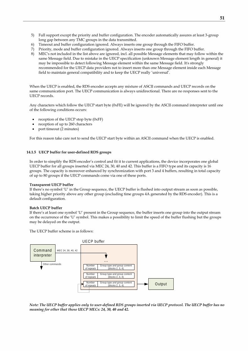
51
5) Full support except the priority and buffer configuration. The encoder automatically assures at least 3-group
long gap between any TMC groups in the data transmitted. 6) Timeout and buffer configuration ignored. Always inserts one group through the FIFO buffer. 7) Priority, mode and buffer configuration ignored. Always inserts one group through the FIFO buffer. 8) MEC's not included in the list above are ignored, incl. all possible Message elements that may follow within the
same Message field. Due to mistake in the UECP specification (unknown Message element length in general) it may be impossible to detect following Message element within the same Message field. It's strongly recommended for the UECP data providers not to insert more than one Message element inside each Message field to maintain general compatibility and to keep the UECP really ‘universal’.
When the UECP is enabled, the RDS encoder accepts any mixture of ASCII commands and UECP records on the same communication port. The UECP communication is always unidirectional. There are no responses sent to the UECP records. Any characters which follow the UECP start byte (0xFE) will be ignored by the ASCII command interpreter until one of the following conditions occurs:
reception of the UECP stop byte (0xFF)
reception of up to 260 characters
port timeout (2 minutes)
For this reason take care not to send the UECP start byte within an ASCII command when the UECP is enabled.
14.1.5 UECP buffer for user-defined RDS groups In order to simplify the RDS encoder’s control and fit it to current applications, the device incorporates one global UECP buffer for all groups inserted via MEC 24, 30, 40 and 42. This buffer is a FIFO type and its capacity is 16 groups. The capacity is moreover enhanced by synchronization with port 3 and 4 buffers, resulting in total capacity of up to 80 groups if the UECP commands come via one of these ports. Transparent UECP buffer If there’s no symbol ‘U’ in the Group sequence, the UECP buffer is flushed into output stream as soon as possible, taking higher priority above any other group (excluding time groups 4A generated by the RDS encoder). This is a default configuration. Batch UECP buffer If there’s at least one symbol ‘U’ present in the Group sequence, the buffer inserts one group into the output stream on the occurrence of the ‘U’ symbol. This makes a possibility to limit the speed of the buffer flushing but the groups may be delayed on the output. The UECP buffer scheme is as follows:
Com m and
interpreter
UECP buffer
Group type and group content(blocks 2, 3, 4)
Number of repeats
Group type and group content(blocks 2, 3, 4)
Number of repeats
Group type and group content(blocks 2, 3, 4)
Number of repeats
Output
...
MEC 24, 30, 40, 42
Other commands
Note: The UECP buffer applies only to user-defined RDS groups inserted via UECP protocol. The UECP buffer has no meaning for other that those UECP MECs: 24, 30, 40 and 42.

52
14.2 Traffic Message Channel (TMC) Application Notes
14.2.1 Basic requirements
The TMC service can work only if there is an application that we can call 'TMC data provider'. The TMC data provider collects all related information and translates it into RDS groups 8A type. The output of the TMC data provider must be either by means of ASCII command G= or (more often) coded as UECP command with MEC 30. We will deal with the second case in following text. Nowadays the TMC service is coded as an ODA application. Thus there must be ODA AID groups 3A transmitted in addition to the 8A groups. This can be done for example using the UECP MEC 24. The 3A groups typically carry fixed content so in some cases they can be inserted into the RDS encoder also one-time using the command UDG1= or UDG2=. The Address and Site fields are optional. When the TMC data provider drives one RDS encoder only, these fields are usually set to zero. However there can be more RDS encoders connected with various Address and Site values. Each encoder will accept only the UECP records that match the Address and Site criteria. This configuration has been tested successfully simulating a network of more than 60 encoders (equivalent to full load of one 9600 bps channel).
14.2.2 Preparing for the TMC transmission
1. Configure all static parameters of the RDS encoder (PI, PS, CT etc.). Enable the UECP (UECP=1 *UECP).
2. Where required, store the fixed 3A groups using the commands UDG1= or UDG2=
(for example: UDG1=30100646CD46,30104080CD46 *UDG1). In this case make sure the UDG groups are included in the Group sequence (symbols X or Y).
3. Decide for the communication settings. Configure the RDS encoder and TMC data provider ports. 4. Configure the Site and Address values.
14.2.3 Application example This application example shows TMC data and ODA AID information inserted by UECP commands 30 and 24.
Time Group UECP command Comment
...
9:27:58 3A: 8A 0646 CD46 FE 00 00 D0 07 24 06 10 06 46 CD 46 B9 68 FF ODA AID variant 0
9:27:58 8A: 07 C801 4689 FE 00 00 D1 08 30 06 06 07 C8 01 46 89 94 54 FF TMC 8A, two repeats
9:27:59 8A: 07 4984 6000 FE 00 00 D2 08 30 06 06 07 49 84 60 00 F2 5C FF TMC 8A, two repeats
9:27:59 3A: 8A 4080 CD46 FE 00 00 D3 07 24 06 10 40 80 CD 46 49 7E FF ODA AID variant 1
9:28:00 - FE 00 00 D4 09 0D 0A 0C 10 09 1C 00 00 02 60 F3 FF Encoder time adjust
9:28:00 8A: 01 883D 1A74 FE 00 00 D5 08 30 06 06 01 88 3D 1A 74 5F DC FF TMC 8A, two repeats
9:28:00 3A: 8A 0646 CD46 FE 00 00 D6 07 24 06 10 06 46 CD 46 E3 E0 FF ODA AID variant 0
9:28:01 8A: 02 8F50 15DD FE 00 00 D7 08 30 06 06 02 8F 50 15 DD D3 6E FF TMC 8A, two repeats
9:28:01 8A: 02 5404 ABD4 FE 00 00 D8 08 30 06 06 02 54 04 AB D4 1D E6 FF TMC 8A, two repeats
9:28:01 3A: 8A 4080 CD46 FE 00 00 D9 07 24 06 10 40 80 CD 46 A6 E6 FF ODA AID variant 1
9:28:02 8A: 05 497C 8000 FE 00 00 DA 08 30 06 06 05 49 7C 80 00 A6 D5 FF TMC 8A, two repeats
...
Notes: 1) Any RDS group inserted using the UECP elements 24, 30, 40 or 42 is put into the UECP buffer. See section 14.1.5
for more details. For TMC transmission it is recommended to leave the UECP buffer as transparent so the TMC data providing application has full control over the TMC transmission. The encoder automatically ensures at least 3-groups long gap between TMC groups.

53
15 Annexes
15.1 Character set and code-table conversions The RDS system, as defined by the standards, does not support Unicode character set. Default character set (G0) used within the RDS system is limited to the characters provided in following EBU Latin code-table.
Example of use: Character 'é' can be found in the table on coordinates 8, 2. Thus it converts to ASCII character 0x82 (HEX) or 130. A conversion is required for all characters outside the basic set region. If you use MagicRDS control software, the characters are converted automatically between Windows ANSI coding and RDS character set. Setting for that feature can be made in Preferences - Local settings. Embedded internet functions are based on UTF-8 coding – conversion is made automatically inside the RDS encoder. Notes:
Many commercially available receivers use 14-segment LCD displays. These receivers are able to display only a limited part of the basic character set (green framed) and do not support the extended set at all. All lower-case characters are showed as upper-case.
The EBU Latin basic set is compatible with most of other systems so conversion is not required for this region.
Since many receivers contain no support for the extended character set, it is recommended to keep all characters in all text messages in the basic set region.
Auxiliary code-tables (G1, G2) are not discussed in this manual as they are not intended for common use due to lack of support on most receivers and incorrect interpretation of repertoire control characters on such receivers.
Basic set Extended set

54
15.2 Communication Protocol Implementation Flowcharts Following flowcharts allow the developer to implement the P132 ASCII protocol to any application easily.
15.2.1 Unidirectional Communication
Send command basic flowchart (unidirectional communication).
15.2.2 Bidirectional Communication Confirm sequences definition:
CS1=Chr(13)+Chr(10)+’+’+Chr(13)+Chr(10)+Chr(13)+Chr(10) CS2=Chr(13)+Chr(10)+’!’+Chr(13)+Chr(10)+Chr(13)+Chr(10) CS3=Chr(13)+Chr(10)+’-’+Chr(13)+Chr(10)+Chr(13)+Chr(10) CS4=Chr(13)+Chr(10)+’/’+Chr(13)+Chr(10)+Chr(13)+Chr(10)
Variables used:
STR, REC, CS, COMMAND: string ACCEPTED, ERROR: integer/boolean TIME: time/float
Other values:
TIMEOUT: COM port timeout, usually ≥400 milliseconds
Calling examples:
SendBD(‘PS=PRO 88’) if ERROR or not ACCEPTED then write(‘Error’) S=Read(‘PS’) if ERROR or not ACCEPTED then S=’’
Note: The flowcharts are valid for any ECHO value.
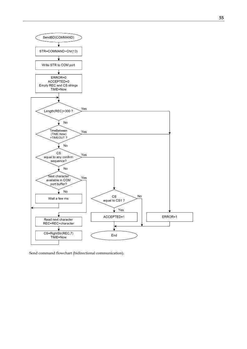
55
Send command flowchart (bidirectional communication).

56
Read value flowchart.

57
15.3 RDS Group Format Following information is provided for better understanding to the RDS principles and the user defined group coding. The largest element in the RDS coding structure is called a "group" of 104 bits each. Each group comprises 4 blocks of 26 bits each. Each block comprises an information word and a checkword. Each information word comprises 16 bits. Each checkword comprises 10 bits. All information words, checkwords, binary numbers or binary address values have their most significant bit (MSB) transmitted first. The data transmission is fully synchronous and there are no gaps between the groups or blocks. The basic data-rate of the system is 1187.5 bit/s. Thus transmission of one group takes about 87.6 ms and about 11.4 groups are transmitted per one second.
General RDS group format.
15.3.1 Basic principles and rules The services which are to be repeated most frequently, and for which a short acquisition time is required (PI, TP,
PTY), in general occupy the same fixed positions within every group. There is no fixed rhythm of repetition of the various types of group, i.e. there is ample flexibility to interleave the
various kinds of message to suit the needs of the users at any given time. The first four bits of the second block of every group are allocated to a four-bit code which specifies the
application of the group - group type. Groups are referred to as types 0 to 15. For each type (0 to 15) two "versions" can be defined. The "version" is specified by the fifth bit of block 2: 0 =
version A, 1 = version B. For all groups of version B the PI is inserted also in block 3 so this block cannot carry any other information when
version B of the group is used.
15.3.2 Remarks One complete PS label consists of 4 groups. So one PS takes 350 ms of the transmission time. It may be found from
experience that any RDS text should be transmitted at least twice to improve reception reliability. With regard to other services included in the RDS the repetition rate of dynamic/scrolling PS usually cannot be lower than one second.
Checkwords and offsets are always computed and inserted automatically by the RDS encoder. PI is always inserted automatically by the RDS encoder in block 1, and also in block 3 for version B of the group.
Due to this the block 1 is never specified when inserting any user defined group. TP and PTY are always inserted automatically by the RDS encoder using OR method (logical sum) on the
appropriate bit positions.

58
15.3.3 TDC group coding (5A, 5B)
Group format in hexadecimal representation (version A): 50BBCCCCDDDD, group format in hexadecimal representation (version B): 58BB0000DDDD, where BB, CCCC and DDDD represent the contents of the block 2 (bits 4 to 0), block 3 and block 4.
15.3.4 IH group coding (6A, 6B)
Group format in hexadecimal representation (version A): 60BBCCCCDDDD,
group format in hexadecimal representation (version B): 68BB0000DDDD, where BB, CCCC and DDDD represent the contents of the block 2 (bits 4 to 0), block 3 and block 4.
15.3.5 AID for ODA group coding (3A)
Group format in hexadecimal representation: 30BBCCCCDDDD, where BB, CCCC and DDDD represent the contents of the block 2 (bits 4 to 0), block 3 and block 4. These groups are used to identify the Open Data Application in use, on an RDS transmission. The type 3A group conveys, to a receiver, information about which Open Data Applications are carried on a particular transmission (AID Code) and in which groups they will be found (Application group type code). The Application group type code and the AID Code are obligatory, while the Message field is optional and should be set to zeros if not used.
Since the 3A groups usually carry fixed static content, they may be inserted using either the UDG1= or UDG2= command for automatic cyclic transmission while the ODA application groups may be inserted by any command or method (G=, UDG1=, UDG2= or UECP MEC 24 or 42).

59
15.3.6 Example of ODA user defined group coding (Radiotext Plus) Let’s show the group coding example on the popular RT+ service. We need to insert group type 3A (Application identification for ODA) to the RDS stream pointing to the RT+ service which is – in this example - carried in group 11A. Let's assume following RT content: Enigma - The Eyes of Truth Appropriate 3A and 11A groups have following structure and coding:
Let's assume following variable values: AGT: group type 11, version A (0), rfu: reserved, set as zeros, CB flag: 0, SC flag: 0, TN: N/A, set as zeros, AID code is 4BD7 for the RT+ service. Blocks 2 to 4 in binary representation: 0011 0000 0001 0110 | 0000 0000 0000 0000 | 0100 1011 1101 0111 Blocks 2 to 4 in hexadecimal representation: 3016 | 0000 | 4BD7
Let's assume following variable values: AGT: group type 11, version A (0), ITG: 0, IRB: 1, RTCT1: 1 (Title), SM1: 9 (10th RT character), LM1: 16 (17 characters long), RTCT2: 4 (Artist), SM2: 0 (first RT character), LM2: 5 (6 characters long). Blocks 2 to 4 in binary representation: 1011 0000 0000 1000 | 0010 0100 1010 0000 | 0010 0000 0000 0101 Blocks 2 to 4 in hexadecimal representation: B008 | 24A0 | 2005 Inserting the RT+ groups using the UDG1 command: UDG1=301600004BD7,B00824A02005
Note: This example is for illustration only. The RT+ feature is directly supported by the RDS encoder (see section 12.7).
Group 3A
Group 11A

60
15.4 Troubleshooting The RDS encoder has been designed to make its use as easy and painless as possible. However, success depends upon a number of settings and things working together correctly. While correcting problems is usually quite simple, the difficulty lays in knowing where to look. Factory default settings assure right operation after first power-on. This section of the manual is designed to assist you in determining the cause of problems that may occur so they can be fixed quickly.
Problem Section related
Solution / Check
Windows control software Terminal
No RDS output, no LED indication.
5.3 Power supply problem.
No RDS output, LED indicates operation.
5.1 5.4.1 13.2
RDS output connected to right input of the transmitter? Adjust higher RDS level or higher input sensitivity on the transmitter. RDS generator switched on?
RDS Encoder – Special – Switch on RDS
RDSGEN=1
The unit does not communicate with PC and the LED does not indicate data receive.
5.5.7 11.1 13.2
Make sure all connectors are seated completely. Make sure you have selected right COM port.
Options – Preferences – List...
Try the unit with different cable and different PC.
The unit does not communicate with PC but the LED indicates that data are received.
11.2 12.6 12.7 13.2
Port 1 baudrate differs from the device configuration.
Address does not match (applies to UECP only)
Enable Bidirectional and Autodetect port speed options (Options – Preferences) RDS Encoder – Device Setup – Set Defaults - Store
Try typing any command on each baudrate.
Radiotext stopped working although I’m sure that it’s enabled and entered correctly.
12.7
The RT service is not included in the Group sequence. The Group sequence may be initialized to its default value.
RDS Encoder – Special – Group sequence – Default, Store.
GRPSEQ=
Pilot tone is fed to the unit but it is not indicated.
5.1 System sheet – Clock Source: Auto, Store
EXTSYNC=1
The unit loses time and date after power off.
4.1 4.2
Replace the on-board battery.
The audio is distorted. There is a whistling in the audio.
5.1 5.2
5.4.1
The unit is not connected in loopthrough mode but the loopthrough switch is in LOOP position. Switch to the SIDE position.
The RDS level considerably exceeds maximum value allowed. Adjust lower RDS level. Use an FM analyzer for the best result.
Applied input of the transmitter is not suitable for RDS. Follow the transmitter’s documentation.
No audio on air 5.1 5.2
The unit is connected in loopthrough mode but the loopthrough switch is in SIDE position. Switch to the LOOP position.


![8 Sima review RDS Spec Iss 4 reprint[1] de2](https://static.fdokumen.com/doc/165x107/631b167a2784ca2fc00526da/8-sima-review-rds-spec-iss-4-reprint1-de2.jpg)