Adsorption of precious metal ions onto electrochemically oxidized carbon fibers
This article was published in an Elsevier journal. The attached copyis furnished to the author for non-commercial research and
education use, including for instruction at the author’s institution,sharing with colleagues and providing to institution administration.
Other uses, including reproduction and distribution, or selling orlicensing copies, or posting to personal, institutional or third party
websites are prohibited.
In most cases authors are permitted to post their version of thearticle (e.g. in Word or Tex form) to their personal website orinstitutional repository. Authors requiring further information
regarding Elsevier’s archiving and manuscript policies areencouraged to visit:
http://www.elsevier.com/copyright
Author's personal copy
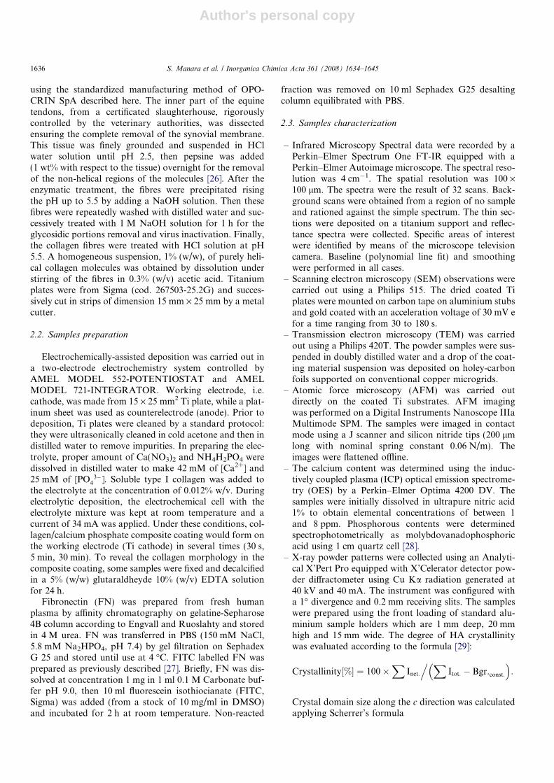
Electrochemically-assisted deposition of biomimetichydroxyapatite–collagen coatings on titanium plate
S. Manara a, F. Paolucci a, B. Palazzo a, M. Marcaccio a, E. Foresti a, G. Tosi b,S. Sabbatini b, P. Sabatino a, G. Altankov c, N. Roveri a,*
a Dipartimento di Chimica ‘‘G. Ciamician’’ Alma Mater Studiorum, Universita di Bologna, via Selmi 2, Bologna I-40126, Italyb Dipartimento di Scienze e Tecnologie Chimiche, Universita Politecnica delle Marche, Ancona , Italy
c ICREA (Institucio Catalana de Recerca i Estudis Avancats) and IBEC (Institut de Bioenginyeria de Catalunya), Nanobioengineering,
Parc Cientific de Barcelona, Josep Samitier 1-5, Barcelona, Spain
Received 1 December 2006; received in revised form 14 March 2007; accepted 24 March 2007Available online 7 April 2007
This paper is dedicated to Prof. Piero Zanello, a valued friend and colleague for many years.
Abstract
A biomimetic bone-like composite, made of self-assembled collagen fibrils and carbonate hydroxyapatite nanocrystals, has been per-formed by an electrochemically-assisted deposition on titanium plate. The electrolytic processes have been carried out using a single typeI collagen molecules suspension in a diluted Ca(NO3)2 and NH4H2PO4 solution at room temperature and applying a constant current fordifferent periods of time. Using the same electrochemical conditions, carbonate hydroxyapatite nanocrystals or reconstituted collagenfibrils coatings were obtained. The reconstituted collagen fibrils, hydroxyapatite nanocrystals and collagen fibrils/apatite nanocrystalscoatings have been characterized chemically, structurally and morphologically, as well as for their ability to bind fibronectin (FN). Fou-rier Transform Infrared microscopy has been used to map the topographic distribution of the coating components at different times ofelectrochemical deposition, allowing to single out the individual deposition steps. Moreover, roughness of Ti plate has been found toaffect appreciably the nucleation region of the inorganic nanocrystals. Laser scanning confocal microscopy has been used to characterizethe FN adsorption pattern on a synthetic biomimetic apatitic phase, which exhibits a higher affinity when it is inter-grown with the col-lagen fibrils. The results offer auspicious applications in the preparation of medical devices such as biomimetic bone-like composite-coated metallic implants.� 2007 Elsevier B.V. All rights reserved.
Keywords: Hydroxyapatite–collagen coating; Electrochemically-assisted deposition; Micro-imaging FTIR spectroscopy; Laser scanning confocal micro-scopy; Biomimetic crystal growth; Fibronectin binding
1. Introduction
Bone is among the most complex examples of biominer-alized material [1]. Bone hydroxyapatite (HA) nanocrystalsgrow in intimate contact within collagen fibres, building upa nano-structured composite with characteristic mechani-cal behaviour [2]. In the past few decades, bone mineraliza-
tion was visualized as being a physicochemicalphenomenon in which the collagen matrix acts as a tem-plate upon which the first mineral crystals are formedthrough a nucleation achieved by extracellular, non-livingstructures [3]. Nevertheless, the not yet completely eluci-dated mechanism of cell-mediated collagen mineralizationmay be considered as a sequence of events requiring theinteraction of many different promoting or inhibiting fac-tors [4]. The extraordinary mechanical behaviour of bone,which arises from its hierarchical structure and composite
0020-1693/$ - see front matter � 2007 Elsevier B.V. All rights reserved.
doi:10.1016/j.ica.2007.03.044
* Corresponding author. Fax: +39 051 2099593.E-mail address: [email protected] (N. Roveri).
www.elsevier.com/locate/ica
Available online at www.sciencedirect.com
Inorganica Chimica Acta 361 (2008) 1634–1645

Author's personal copy
nature at a nanometric level, can be hardly reproducedfrom synthetic biomaterials [5].
Different kinds of materials have been used as artificialbone fillers such as metals [6], which are too hard, ceramicmaterials [7], too brittle to be a suitable bone substitute,and natural [8] or synthetic polymers [9] too soft to providea right mechanical support. One drawback of these bioma-terials is that they are bioinert, in fact they have almost noinfluence in the surrounding living tissue and are unable toinduce bone formation and accelerate the healing process[10]. Therefore, many researchers have prepared bioactivematerials such as calcium phosphate bioceramics which,by partially dissolving themselves in biological environ-ment, guide new bone formation and form a tight bondwith the newly formed bone. They exhibit biocompatibility,bioactivity, osteoconductivity and bioreabsorbability, sothat they may be completely substituted by newly formedbone [11]. The bioceramics powders have been usuallymixed with a polymeric carrier matrix in order to avoidtheir migration out of the implant region. Both non-absorbable and biodegradable polymeric matrices havebeen used. In order to simulate bone composition, collage-nous matrices constituted of gelatin have been widelyemployed. Gelatine, which is obtained by physicochemicaldegradation of collagen, is completely bioresorbable in aphysiological environment [12].
A new generation of bone substitutes constituted of col-lagen and calcium phosphates composites have recentlyreceived much attention because they can mimic not onlythe composition, but also the complex hierarchical struc-ture of bone [13]. Differently of what can be achieved bygelatine, which presents a denaturated protein fragmentsdistribution not able to recover protein fibril structure, col-lagen type I molecules can store and transfer informationat a molecular level up to a spontaneous self-assembly informing reconstituted protein fibrils [14]. Removal of thetelopeptidic portions of the single molecules allows a betterreconstitution in vitro of collagen fibrils than in presence oftelopeptides [15]. Direct nucleation in aqueous solutions ofHA nanocrystals into reconstituted type I collagen fibresduring their self-assembling allows to obtain a bone-likecomposite with needle-shaped HA nanocrystals, orientedwith the sixfold symmetry axis parallel to the long axis ofcollagen fibres [16]. The similarity of apatite–collagennanocomposites with bone tissue in microstructure andcomposition leads to an increase in bioactivity and biode-gradability of the composite itself [17]. The study of the tis-sue response of HA nanocrystals–collagen implants inmarrow cavities has put in evidence that apatite nanoparti-cles allowed for a quicker implant surface turnover,implant resorption and bone substitution having a kineticsimilar to bone remodelling [10]. Calcium phosphate/colla-gen composites exhibit weak mechanical behaviour whichcan be improved by chemical cross linking of collagen,but reducing their bioresorption ability [18]. They are lim-ited to non-loading application, but are particularly suit-able to perform a bioactive coating onto the surface of
metallic implants and to accelerate bone formation andimplant fixation.
One of the most promising technique in the productionof composite coatings is the electrochemically-assisteddeposition onto a metallic surface. This method not onlyallows to overcome the difficulty of depositing proteincomponent by plasma spray or physical vapour deposition,but also allows to control the coating process easily.
Calcium phosphate coatings have been obtained by elec-trochemically-assisted deposition from different Ca2+ andPO4
3� solutions, in acidic and in basic conditions, but alsoat physiological pH [19]. Trying to approach this goal,recently a hydroxyapatite coating has been deposited onTi plates using a hydrothermal electrochemical method,in the presence of calcium and phosphate ions, revealinga preferential growth direction along the (002) planes ofthe HA nanocrystals [20].
To the best of our knowledge, a biomimetic collagen/hydroxyapatite coating starting from type I collagen singlemolecules suspension has not been previously obtained byan electrochemically-assisted process. In fact, some authorshave synthesized non-apatitic calcium phosphate collagencoating [21]. On the other hand, apatitic–collagen coatinghas been performed by researchers who have used commer-cially available collagen in gelatine form containing amolecular weight distribution [22]. Only few papers reportthe use of a single type I collagen molecules suspension, butit must be pointed out that in the literature either proteiccoating deposition has been obtained changing the pHsolution by chemicals [21] or previously chemically recon-stituted fibres have been electrochemically deposited [23].
In the present work, the electrochemically-assisted depo-sition of a biomimetic collagen fibrils/HA nanocrystalscomposite on titanium substrate is first reported, using asynergic process in which the collagen molecules self-assembly takes place during the nanocrystals nucleation.Aim of this study is also to define the structural interac-tions between hydroxyapatite nanocrystals and reconsti-tuted collagen fibres as a function of the differentelectrochemical deposition times. Fourier Transform Infra-red microscopy has been used to map the topographic dis-tribution of the proteic and inorganic components duringthe coating formation, allowing to single out the individualdeposition steps. Moreover, the ability of the above coat-ings to bind fibronectin (FN) [24] was investigated in orderto test their bioactivity [25].
Our results offer auspicious applications in the prepara-tion of bone-like composite-coated metallic implants hav-ing a bioactive surface able to accelerate bone formationand implant fixation.
2. Materials and methods
2.1. Materials
All the chemicals used were of high chemical grade.Type I collagen was extracted from equine Achilles tendon
S. Manara et al. / Inorganica Chimica Acta 361 (2008) 1634–1645 1635
Author's personal copy
using the standardized manufacturing method of OPO-CRIN SpA described here. The inner part of the equinetendons, from a certificated slaughterhouse, rigorouslycontrolled by the veterinary authorities, was dissectedensuring the complete removal of the synovial membrane.This tissue was finely grounded and suspended in HClwater solution until pH 2.5, then pepsine was added(1 wt% with respect to the tissue) overnight for the removalof the non-helical regions of the molecules [26]. After theenzymatic treatment, the fibres were precipitated risingthe pH up to 5.5 by adding a NaOH solution. Then thesefibres were repeatedly washed with distilled water and suc-cessively treated with 1 M NaOH solution for 1 h for theglycosidic portions removal and virus inactivation. Finally,the collagen fibres were treated with HCl solution at pH5.5. A homogeneous suspension, 1% (w/w), of purely heli-cal collagen molecules was obtained by dissolution understirring of the fibres in 0.3% (w/v) acetic acid. Titaniumplates were from Sigma (cod. 267503-25.2G) and succes-sively cut in strips of dimension 15 mm · 25 mm by a metalcutter.
2.2. Samples preparation
Electrochemically-assisted deposition was carried out ina two-electrode electrochemistry system controlled byAMEL MODEL 552-POTENTIOSTAT and AMELMODEL 721-INTEGRATOR. Working electrode, i.e.cathode, was made from 15 · 25 mm2 Ti plate, while a plat-inum sheet was used as counterelectrode (anode). Prior todeposition, Ti plates were cleaned by a standard protocol:they were ultrasonically cleaned in cold acetone and then indistilled water to remove impurities. In preparing the elec-trolyte, proper amount of Ca(NO3)2 and NH4H2PO4 weredissolved in distilled water to make 42 mM of [Ca2+] and25 mM of [PO4
3�]. Soluble type I collagen was added tothe electrolyte at the concentration of 0.012% w/v. Duringelectrolytic deposition, the electrochemical cell with theelectrolyte mixture was kept at room temperature and acurrent of 34 mA was applied. Under these conditions, col-lagen/calcium phosphate composite coating would form onthe working electrode (Ti cathode) in several times (30 s,5 min, 30 min). To reveal the collagen morphology in thecomposite coating, some samples were fixed and decalcifiedin a 5% (w/w) glutaraldheyde 10% (w/v) EDTA solutionfor 24 h.
Fibronectin (FN) was prepared from fresh humanplasma by affinity chromatography on gelatine-Sepharose4B column according to Engvall and Ruoslahty and storedin 4 M urea. FN was transferred in PBS (150 mM NaCl,5.8 mM Na2HPO4, pH 7.4) by gel filtration on SephadexG 25 and stored until use at 4 �C. FITC labelled FN wasprepared as previously described [27]. Briefly, FN was dis-solved at concentration 1 mg in 1 ml 0.1 M Carbonate buf-fer pH 9.0, then 10 ml fluorescein isothiocianate (FITC,Sigma) was added (from a stock of 10 mg/ml in DMSO)and incubated for 2 h at room temperature. Non-reacted
fraction was removed on 10 ml Sephadex G25 desaltingcolumn equilibrated with PBS.
2.3. Samples characterization
– Infrared Microscopy Spectral data were recorded by aPerkin–Elmer Spectrum One FT-IR equipped with aPerkin–Elmer Autoimage microscope. The spectral reso-lution was 4 cm�1. The spatial resolution was 100 ·100 lm. The spectra were the result of 32 scans. Back-ground scans were obtained from a region of no sampleand rationed against the simple spectrum. The thin sec-tions were deposited on a titanium support and reflec-tance spectra were collected. Specific areas of interestwere identified by means of the microscope televisioncamera. Baseline (polynomial line fit) and smoothingwere performed in all cases.
– Scanning electron microscopy (SEM) observations werecarried out using a Philips 515. The dried coated Tiplates were mounted on carbon tape on aluminium stubsand gold coated with an acceleration voltage of 30 mV efor a time ranging from 30 to 180 s.
– Transmission electron microscopy (TEM) was carriedout using a Philips 420T. The powder samples were sus-pended in doubly distilled water and a drop of the coat-ing material suspension was deposited on holey-carbonfoils supported on conventional copper microgrids.
– Atomic force microscopy (AFM) was carried outdirectly on the coated Ti substrates. AFM imagingwas performed on a Digital Instruments Nanoscope IIIaMultimode SPM. The samples were imaged in contactmode using a J scanner and silicon nitride tips (200 lmlong with nominal spring constant 0.06 N/m). Theimages were flattened offline.
– The calcium content was determined using the induc-tively coupled plasma (ICP) optical emission spectrome-try (OES) by a Perkin–Elmer Optima 4200 DV. Thesamples were initially dissolved in ultrapure nitric acid1% to obtain elemental concentrations of between 1and 8 ppm. Phosphorous contents were determinedspectrophotometrically as molybdovanadophosphoricacid using 1 cm quartz cell [28].
– X-ray powder patterns were collected using an Analyti-cal X’Pert Pro equipped with X’Celerator detector pow-der diffractometer using Cu Ka radiation generated at40 kV and 40 mA. The instrument was configured witha 1� divergence and 0.2 mm receiving slits. The sampleswere prepared using the front loading of standard alu-minium sample holders which are 1 mm deep, 20 mmhigh and 15 mm wide. The degree of HA crystallinitywas evaluated according to the formula [29]:
Crystallinity½%� ¼ 100�X
Inet:
. XItot: � Bgr:const:
� �:
Crystal domain size along the c direction was calculatedapplying Scherrer’s formula
1636 S. Manara et al. / Inorganica Chimica Acta 361 (2008) 1634–1645

Author's personal copy
Lð002Þ ¼0:94k
cos hðffiffiffiffiffiffiffiffiffiffiffiffiffiffiffiffiffiffiDr2 � D2
0
qÞ
� �
where h is the diffraction angle for plane (002), Dr andD0 are the widths in radians of reflection (002) at halfheight for the synthesized and the reference HA materi-als, respectively, and k = 1.5405 A.
– For coating with FITC-FN, samples were incubated in20 lg/ml FITC-FN solution in PBS for 30 min at37 �C, then washed three times with PBS, once with dis-tilled water and mounted with cover glass via Moviol.
3D Fluorescent images were captured with laser scan-ning confocal Microscope (LSM) Leika SP2 (Germany)at magnification 20· using z-stack mode. Image sequenceswere stored and examined by LSM Image Examinersoftware.
3. Results and discussion
Mineral, collagen and mineral/collagen coatings havebeen obtained by an electrochemically-assisted process
applying a constant current to the cathode constituted ofa Ti plate for different periods of time, from 30 s up to30 min. Starting Ti plates surfaces resulted quite roughwith many grooves and harshness by SEM observations(Fig. 1). From the AFM surface analyses, an averageroughness of about 50 nm height has been appreciated(Fig. 2a). The main reactions which occur at the Ti cathodecomprise the reduction of dissolved oxygen and reductivereduction of water, both resulting in the generation ofOH� ions and the ensuing increase of pH in the vicinityof the electrode surface. Since the self-assembling of colla-gen molecules into fibrils occur at pH above 5.5 and theprecipitation of calcium phosphates occurs at alkalinepH, this experimental strategy can be profitably used todeposit a collagen/calcium phosphate coating onto theelectrode without changing the solution pH by addingbasic reagents.
Three sets of experiments have been carried out in orderto evaluate separately hydroxyapatite nanocrystals crystal-lization, collagen molecules self-assembly and collagenfibrils–hydroxyapatite nanocrystals composite depositionon the Ti plates. Both applied current and maximum depo-sition time have been optimized, finding out the best condi-tions in order to get a homogeneous coating and asignificant rate of deposition at the same time.
During the electrochemically-assisted process, in fact,hydrogen bubbles evolve from the electrode surface thusaffecting the coating adhesion. The entity of this processis a function of the current applied, the reagents concentra-tion and the surface morphology of the electrode immersedin the electrolyte solution.
Moreover, the amount of mineral deposited has beencontrolled through the reaction time. The upper limit ofdeposited mineral has been evaluated as 3 mg/cm2 corre-sponding to a deposition time of 30 min. At higher deposi-tion time the mineral coating easily detaches from thesurface.
Fig. 1. SEM image of Ti plate before the electrolytic deposition, scale bar50 lm.
Fig. 2. AFM image: Ti plate before (a) and after (b) the HA electrolytic deposition (30 s): the red line indicates the mineral deposition front (b), scalebar = 200 nm. (For interpretation of the references to color in this figure legend, the reader is referred to the web version of this article.)
S. Manara et al. / Inorganica Chimica Acta 361 (2008) 1634–1645 1637
Author's personal copy
We have chosen to report the results obtained after 30 s,5 min and 30 min in order to appreciate the evolving of themineral, collagen and HA–collagen composite coatingdeposition.
3.1. Hydroxyapatite nanocrystals coating
The electrochemical deposition of calcium phosphateson the Ti surface has been carried out using Ca(NO3)2
and NH4H2PO4 solutions. Calcium phosphate depositiontakes place for the reaction of Ca2+ ions as OH� ions(and therefore PO4
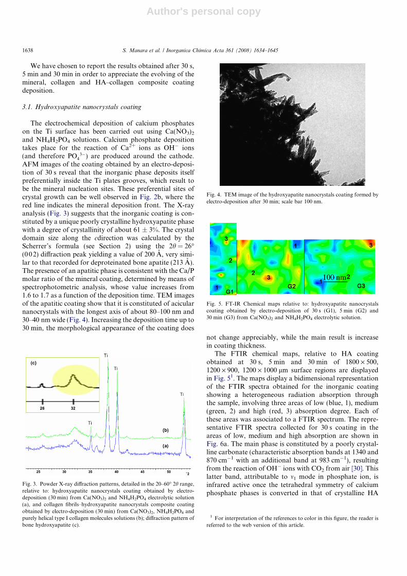
3�) are produced around the cathode.AFM images of the coating obtained by an electro-deposi-tion of 30 s reveal that the inorganic phase deposits itselfpreferentially inside the Ti plates grooves, which result tobe the mineral nucleation sites. These preferential sites ofcrystal growth can be well observed in Fig. 2b, where thered line indicates the mineral deposition front. The X-rayanalysis (Fig. 3) suggests that the inorganic coating is con-stituted by a unique poorly crystalline hydroxyapatite phasewith a degree of crystallinity of about 61 ± 3%. The crystaldomain size along the cdirection was calculated by theScherrer’s formula (see Section 2) using the 2h = 26�(002) diffraction peak yielding a value of 200 A, very simi-lar to that recorded for deproteinated bone apatite (213 A).The presence of an apatitic phase is consistent with the Ca/Pmolar ratio of the mineral coating, determined by means ofspectrophotometric analysis, whose value increases from1.6 to 1.7 as a function of the deposition time. TEM imagesof the apatitic coating show that it is constituted of acicularnanocrystals with the longest axis of about 80–100 nm and30–40 nm wide (Fig. 4). Increasing the deposition time up to30 min, the morphological appearance of the coating does
not change appreciably, while the main result is increasein coating thickness.
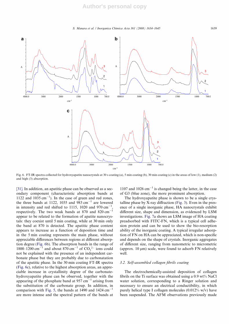
The FTIR chemical maps, relative to HA coatingobtained at 30 s, 5 min and 30 min of 1800 · 500,1200 · 900, 1200 · 1000 lm surface regions are displayedin Fig. 51. The maps display a bidimensional representationof the FTIR spectra obtained for the inorganic coatingshowing a heterogeneous radiation absorption throughthe sample, involving three areas of low (blue, 1), medium(green, 2) and high (red, 3) absorption degree. Each ofthese areas was associated to a FTIR spectrum. The repre-sentative FTIR spectra collected for 30 s coating in theareas of low, medium and high absorption are shown inFig. 6a. The main phase is constituted by a poorly crystal-line carbonate (characteristic absorption bands at 1340 and870 cm�1 with an additional band at 983 cm�1), resultingfrom the reaction of OH� ions with CO2 from air [30]. Thislatter band, attributable to m1 mode in phosphate ion, isinfrared active once the tetrahedral symmetry of calciumphosphate phases is converted in that of crystalline HA
Fig. 3. Powder X-ray diffraction patterns, detailed in the 20–60� 2h range,relative to: hydroxyapatite nanocrystals coating obtained by electro-deposition (30 min) from Ca(NO3)2 and NH4H2PO4 electrolytic solution(a), and collagen fibrils–hydroxyapatite nanocrystals composite coatingobtained by electro-deposition (30 min) from Ca(NO3)2, NH4H2PO4 andpurely helical type I collagen molecules solutions (b); diffraction pattern ofbone hydroxyapatite (c).
1 For interpretation of the references to color in this figure, the reader isreferred to the web version of this article.
Fig. 4. TEM image of the hydroxyapatite nanocrystals coating formed byelectro-deposition after 30 min; scale bar 100 nm.
Fig. 5. FT-IR Chemical maps relative to: hydroxyapatite nanocrystalscoating obtained by electro-deposition of 30 s (G1), 5 min (G2) and30 min (G3) from Ca(NO3)2 and NH4H2PO4 electrolytic solution.
1638 S. Manara et al. / Inorganica Chimica Acta 361 (2008) 1634–1645
Author's personal copy
[31]. In addition, an apatitic phase can be observed as a sec-ondary component (characteristic absorption bands at1122 and 1035 cm�1). In the case of green and red zones,the three bands at 1122, 1035 and 983 cm�1 are loweredin intensity and red shifted to 1115, 1020 and 970 cm�1,respectively. The two weak bands at 870 and 820 cm�1
appear to be related to the formation of apatite nanocrys-tals: they coexist until 5 min coating, while at 30 min onlythe band at 870 is detected. The apatitic phase contentappears to increase as a function of deposition time andin the 5 min coating represents the main phase, withoutappreciable differences between regions at different absorp-tion degree (Fig. 6b). The absorption bands in the range of1800–1200 cm�1 and about 870 cm�1 of CO3
2� ions couldnot be explained with the presence of an independent car-bonate phase but they are probably due to carbonatationof the apatitic phase. In the 30 min coating FT-IR spectra(Fig. 6c), relative to the highest absorption areas, an appre-ciable increase in crystallinity degree of the carbonate-hydroxyapatite phase can be observed, together with theappearing of the phosphate band at 957 cm�1 arising fromthe substitution of the carbonate group. In addition, incomparison with Fig. 5, the bands at 1490 and 1424 cm�1
are more intense and the spectral pattern of the bands at
1107 and 1026 cm�1 is changed being the latter, in the caseof G3 (blue zone), the more prominent absorption.
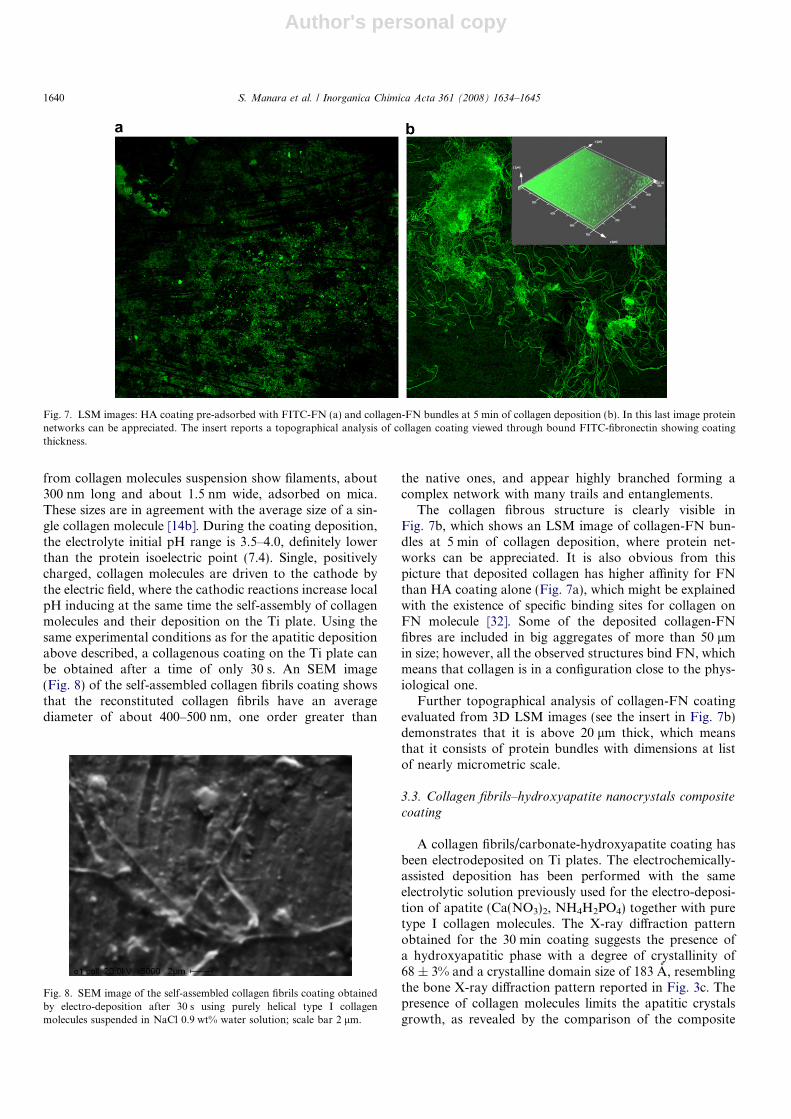
The hydroxyapatite phase is shown to be a single crys-talline phase by X-ray diffraction (Fig. 3). Even in the pres-ence of a single inorganic phase, HA nanocrystals exhibitdifferent size, shape and dimension, as evidenced by LSMinvestigations. Fig. 7a shows an LSM image of HA coatingpreadsorbed with FITC-FN, which is a typical cell adhe-sion protein and can be used to show the bio-resorptionability of the inorganic coating. A typical irregular adsorp-tion of FN on HA can be appreciated, which is non-specificand depends on the shape of crystals. Inorganic aggregatesof different size, ranging from nanometric to micrometric(approx. 10 lm) scale, were found to adsorb FN relativelywell.
3.2. Self-assembled collagen fibrils coating
The electrochemically-assisted deposition of collagenfibrils on the Ti surface was obtained using a 0.9 wt% NaClwater solution, corresponding to a Ringer solution andnecessary to ensure an electrical conductibility, in whichpurely helical type I collagen molecules (0.012% w/v) havebeen suspended. The AFM observations previously made
4000.0 3000 2000 1500 1000 700.0
A
1
2
3
1
2
3
4000.0 3000 2000 1500 1000 700.0
cm-1cm-1
cm-1
A
4000.0 3000 2000 1500 1000 700.0
A
2
3
1
a
c
b
Fig. 6. FT-IR spectra collected for hydroxyapatite nanocrystals at 30 s coating (a), 5 min coating (b), 30 min coating (c) in the areas of low (1), medium (2)and high (3) absorption.
S. Manara et al. / Inorganica Chimica Acta 361 (2008) 1634–1645 1639
Author's personal copy
from collagen molecules suspension show filaments, about300 nm long and about 1.5 nm wide, adsorbed on mica.These sizes are in agreement with the average size of a sin-gle collagen molecule [14b]. During the coating deposition,the electrolyte initial pH range is 3.5–4.0, definitely lowerthan the protein isoelectric point (7.4). Single, positivelycharged, collagen molecules are driven to the cathode bythe electric field, where the cathodic reactions increase localpH inducing at the same time the self-assembly of collagenmolecules and their deposition on the Ti plate. Using thesame experimental conditions as for the apatitic depositionabove described, a collagenous coating on the Ti plate canbe obtained after a time of only 30 s. An SEM image(Fig. 8) of the self-assembled collagen fibrils coating showsthat the reconstituted collagen fibrils have an averagediameter of about 400–500 nm, one order greater than
the native ones, and appear highly branched forming acomplex network with many trails and entanglements.
The collagen fibrous structure is clearly visible inFig. 7b, which shows an LSM image of collagen-FN bun-dles at 5 min of collagen deposition, where protein net-works can be appreciated. It is also obvious from thispicture that deposited collagen has higher affinity for FNthan HA coating alone (Fig. 7a), which might be explainedwith the existence of specific binding sites for collagen onFN molecule [32]. Some of the deposited collagen-FNfibres are included in big aggregates of more than 50 lmin size; however, all the observed structures bind FN, whichmeans that collagen is in a configuration close to the phys-iological one.
Further topographical analysis of collagen-FN coatingevaluated from 3D LSM images (see the insert in Fig. 7b)demonstrates that it is above 20 lm thick, which meansthat it consists of protein bundles with dimensions at listof nearly micrometric scale.
3.3. Collagen fibrils–hydroxyapatite nanocrystals composite
coating
A collagen fibrils/carbonate-hydroxyapatite coating hasbeen electrodeposited on Ti plates. The electrochemically-assisted deposition has been performed with the sameelectrolytic solution previously used for the electro-deposi-tion of apatite (Ca(NO3)2, NH4H2PO4) together with puretype I collagen molecules. The X-ray diffraction patternobtained for the 30 min coating suggests the presence ofa hydroxyapatitic phase with a degree of crystallinity of68 ± 3% and a crystalline domain size of 183 A, resemblingthe bone X-ray diffraction pattern reported in Fig. 3c. Thepresence of collagen molecules limits the apatitic crystalsgrowth, as revealed by the comparison of the composite
Fig. 7. LSM images: HA coating pre-adsorbed with FITC-FN (a) and collagen-FN bundles at 5 min of collagen deposition (b). In this last image proteinnetworks can be appreciated. The insert reports a topographical analysis of collagen coating viewed through bound FITC-fibronectin showing coatingthickness.
Fig. 8. SEM image of the self-assembled collagen fibrils coating obtainedby electro-deposition after 30 s using purely helical type I collagenmolecules suspended in NaCl 0.9 wt% water solution; scale bar 2 lm.
1640 S. Manara et al. / Inorganica Chimica Acta 361 (2008) 1634–1645
Author's personal copy
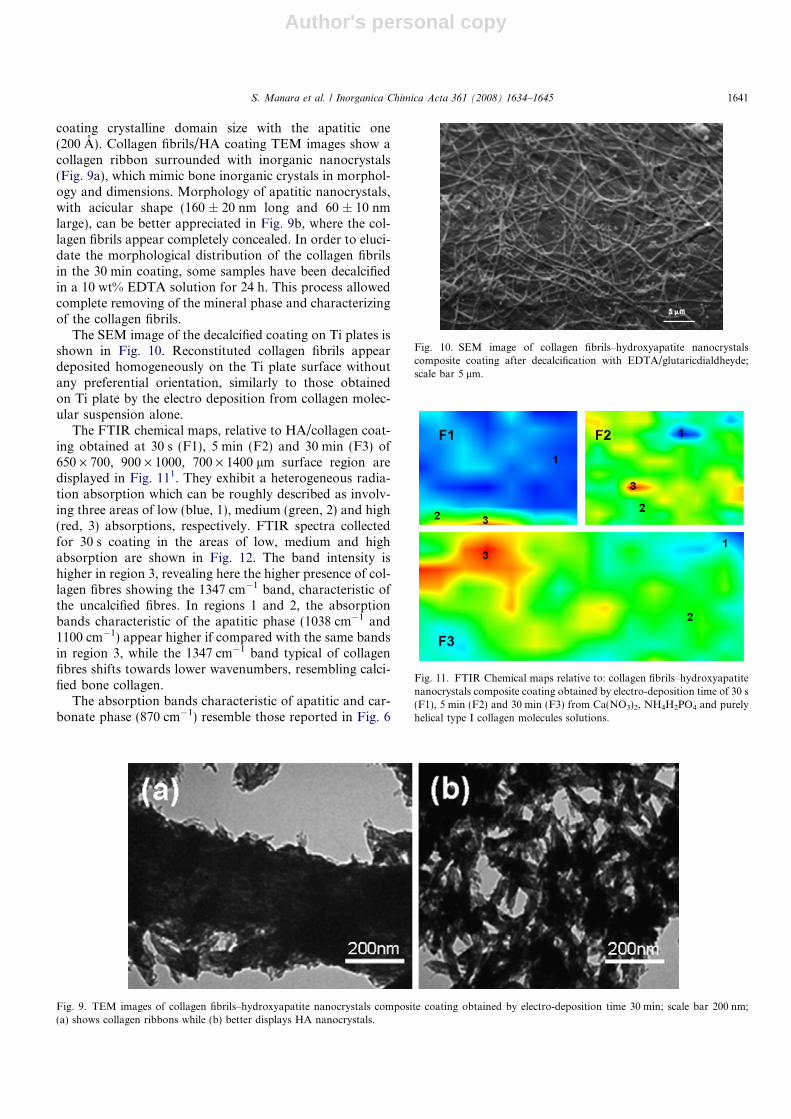
coating crystalline domain size with the apatitic one(200 A). Collagen fibrils/HA coating TEM images show acollagen ribbon surrounded with inorganic nanocrystals(Fig. 9a), which mimic bone inorganic crystals in morphol-ogy and dimensions. Morphology of apatitic nanocrystals,with acicular shape (160 ± 20 nm long and 60 ± 10 nmlarge), can be better appreciated in Fig. 9b, where the col-lagen fibrils appear completely concealed. In order to eluci-date the morphological distribution of the collagen fibrilsin the 30 min coating, some samples have been decalcifiedin a 10 wt% EDTA solution for 24 h. This process allowedcomplete removing of the mineral phase and characterizingof the collagen fibrils.
The SEM image of the decalcified coating on Ti plates isshown in Fig. 10. Reconstituted collagen fibrils appeardeposited homogeneously on the Ti plate surface withoutany preferential orientation, similarly to those obtainedon Ti plate by the electro deposition from collagen molec-ular suspension alone.
The FTIR chemical maps, relative to HA/collagen coat-ing obtained at 30 s (F1), 5 min (F2) and 30 min (F3) of650 · 700, 900 · 1000, 700 · 1400 lm surface region aredisplayed in Fig. 111. They exhibit a heterogeneous radia-tion absorption which can be roughly described as involv-ing three areas of low (blue, 1), medium (green, 2) and high(red, 3) absorptions, respectively. FTIR spectra collectedfor 30 s coating in the areas of low, medium and highabsorption are shown in Fig. 12. The band intensity ishigher in region 3, revealing here the higher presence of col-lagen fibres showing the 1347 cm�1 band, characteristic ofthe uncalcified fibres. In regions 1 and 2, the absorptionbands characteristic of the apatitic phase (1038 cm�1 and1100 cm�1) appear higher if compared with the same bandsin region 3, while the 1347 cm�1 band typical of collagenfibres shifts towards lower wavenumbers, resembling calci-fied bone collagen.
The absorption bands characteristic of apatitic and car-bonate phase (870 cm�1) resemble those reported in Fig. 6
Fig. 9. TEM images of collagen fibrils–hydroxyapatite nanocrystals composite coating obtained by electro-deposition time 30 min; scale bar 200 nm;(a) shows collagen ribbons while (b) better displays HA nanocrystals.
Fig. 10. SEM image of collagen fibrils–hydroxyapatite nanocrystalscomposite coating after decalcification with EDTA/glutaricdialdheyde;scale bar 5 lm.
Fig. 11. FTIR Chemical maps relative to: collagen fibrils–hydroxyapatitenanocrystals composite coating obtained by electro-deposition time of 30 s(F1), 5 min (F2) and 30 min (F3) from Ca(NO3)2, NH4H2PO4 and purelyhelical type I collagen molecules solutions.
S. Manara et al. / Inorganica Chimica Acta 361 (2008) 1634–1645 1641

Author's personal copy
for the inorganic coating, in agreement with the presence ofpoorly crystalline carbonate apatite. As a part of theseapatitic nanocrystals have probably nucleated and growninside the collagen fibres during their assembling, in agree-ment with the shift of the 1347 cm�1 band to lower valuespreviously observed by Kikuchi et al. [13c].
FTIR spectra collected for 5 min coating in the areas oflow, medium and high absorption are shown in Fig. 12.The FTIR pattern collected in region 3 shows the highestamount of collagen and hydroxyapatite, revealing a prefer-ential nucleation and growth of apatitic nanocrystals oncalcified collagen fibres in agreement with TEM observa-tions (Fig. 9). In areas 1 and 2, the lower intensity of theabsorption bands reveals a less amount of protein and inor-ganic phase; however the absorption bands at 1347 cm�1
show that collagen nonetheless mimics bone collagenfibres.
FTIR spectra collected for 30 min coating in the areas oflow, medium and high absorption are shown in Fig. 12. Atthis stage, the spectra appear quite similar, revealing bothcharacteristic absorption bands of crystalline carbonatedHA (1200–900 cm�1, 3500–2800 cm�1 and 870 cm�1) andcollagen bands ranging between 1800 and 1200 cm�1.Composition homogeneity is confirmed by the custommap, where distribution of crystalline HA is evident in
the whole examined surface. Differences in absorptionintensities can be ascribed to differences in thickness ofthe crystalline material. The FTIR spectrum of the electro-chemically-assisted HA–collagen coating reveals that thecoating is a composite made up from both the apatiticand the collagenous phases, as clearly shown in Fig. 12d,taking into account the single spectra of HA and collagenreported. In addition, the FTIR spectrum of the HA–colla-gen coating is compared with that obtained from a turkeycalcified tendon [33] revealing a very close similarity, inagreement with its biomimetic nature.
The Ca/P molar ratio of the mineral coating increasesfrom a value of 1.2 to a value of 1.8 as a function of thedeposition time, according to the evolution of an initialacid phosphate towards a carbonate-hydroxyapatite phasein the final step of mineralization. In fact, the increase ofthe ratio value can be due both to a rearrangement of aphosphatic precursor phase towards a more stoichiometricapatite and to the decrease of the denominator, which canbe attributed to a partial substitution of the phosphate ionswith carbonate ions as a function of the deposition time.
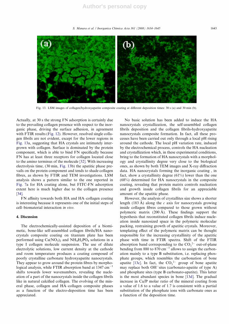
As for the composite LSM images, in Fig. 13 (at 30 sand 30 min deposition, respectively) it is obvious that thepresence of collagen visibly increases FN adsorption, ifcompared to the image in Fig. 7a (HA coating alone).
4000.0 3000 2000 1500 1000 700.0cm-1
4000.0 3000 2000 1500 1000 700.0cm-1
4000.0 3000 2000 1500 1000 700.0cm-1
4000.0 3000 2000 1500 1000 700.0cm-1
A
1
2
3
A
Ha
collagen
Ha_collagen
calcified tendon1
2
3
4
A
2
1
3
1347
A
2
1
3
135 2
1345
a
c d
b
Fig. 12. FT-IR spectra collected for composite coating in the areas of low (1), medium (2) and high (3) absorption for 30 s (a), 5 min (b), 30 min(c) deposition time. We can observe the presence of collagen fibres through absorption bands at 1658 and 1557 cm�1, characteristic of collagen amide I.(d) The FTIR spectrum of the HA–collagen coating compared with that obtained from a turkey calcified tendon.
1642 S. Manara et al. / Inorganica Chimica Acta 361 (2008) 1634–1645
Author's personal copy
Actually, at 30 s the strong FN adsorption is certainly dueto the prevailing collagen presence with respect to the inor-ganic phase, driving the surface adhesion, in agreementwith FTIR results (Fig. 12). However, resolved single colla-gen fibrils are not evident, except for the lower regions inFig. 13a, suggesting that HA crystals are intimately inter-grown with collagen. Surface is dominated by the proteincomponent, which is able to bind FN specifically becauseFN has at least three receptors for collagen located closeto the amino terminus of the molecule [32]. With increasingelectrolysis time, (30 min, Fig. 13b) the apatitic phase pre-vails on the protein component and tends to shade collagenfibres, as shown by FTIR and TEM investigations. LSManalysis shows a pattern similar to the one reported inFig. 7a for HA coating alone, but FITC-FN adsorptionextent here is much higher due to the collagen presence[34].
FN affinity towards both HA and HA–collagen coatingis interesting because it represents one of the initial steps ofcell–biomaterial interaction in vivo.
4. Discussion
The electrochemically-assisted deposition of a biomi-metic, bone-like self-assembled collagen fibrils/HA nano-crystals composite coating on titanium plate has beenperformed using Ca(NO3)2 and NH4H2PO4 solutions in atype I collagen molecule suspension. The use of diluteelectrolytic solutions, low current density at the cathodeand room temperature produces a coating composed ofpoorly crystalline carbonate hydroxyapatite nanocrystals.They appear to grow around the protein fibres by morpho-logical analysis, while FTIR absorption band at 1347 cm�1
shifts towards lower wavenumbers, revealing the nucle-ation of a part of the nanocrystals inside the collagen fibrilslike in natural calcified collagen. The evolving of the min-eral phase, collagen and HA–collagen composite phasesas a function of the electro-deposition time has beenappreciated.
No basic solution has been added to induce the HAnanocrystals crystallization, the self-assembled collagenfibrils deposition and the collagen fibrils-hydroxyapatitenanocrystals composite formation. In fact, all these pro-cesses have been carried out only through a local pH risingaround the cathode. The local pH variation rate, inducedby the electrochemical process, controls the HA nucleationand crystallization which, in these experimental conditions,bring to the formation of HA nanocrystals with a morphol-ogy and crystallinity degree very close to the biologicalones, as shown by both TEM images and X-ray diffractiondata. HA nanocrystals forming the inorganic coating , infact, show a crystallinity degree (61%) lower than the one(68%) determined for HA nanocrystals in the compositecoating, revealing that protein matrix controls nucleationand growth inside collagen fibrils for an appreciableamount of the apatitic phase.
However, the analysis of crystallites size shows a shorterlength (183 A) along the c axis for nanocrystals growinginside collagen fibres compared to those grown withoutpolymeric matrix (200 A). These findings support thehypothesis that reconstituted collagen fibrils induce nucle-ation inside nanosized space in the polymeric molecularpacking, restraining growth of apatitic crystals. Moreover,templating effect of the polymeric matrix can be thoughtresponsible for the increasing crystallinity of the apatiticphase with time in FTIR spectra. Shift of the FTIRabsorption band corresponding to the CO3
2� out-of-planebending from 880 to 870 cm�1 allows to assign the carbon-ation mainly to a type B substitution, i.e. replacing phos-phate groups, which resembles the carbonation of boneapatite [13c]. In fact, the CO3
2� group of bone apatitemay replace both OH�sites (carbonato-apatite of type A)and phosphate sites (type B carbonato-apatite). This latteris the most abundant species in bone [13d]. The gradualincrease in Ca/P molar ratio of the mineral coating froma value of 1.6 to a value of 1.7 is consistent with a partialsubstitution of the phosphate ions with carbonate ones asa function of the deposition time.
Fig. 13. LSM images of collagen/hydroxyapatite composite coating at different deposition times: 30 s (a) and 30 min (b).
S. Manara et al. / Inorganica Chimica Acta 361 (2008) 1634–1645 1643
Author's personal copy
The pH rising around the cathode induces the self-assembling of the telopeptides-free collagen single mole-cules in reconstituted fibrils of 400–500 nm of diameteronto the electrode, forming a homogeneous and uniformprotein coating onto the Ti plate surface. If the telopep-tides-free collagen molecules assembly takes place duringthe crystallization of the apatite phase, the newly reconsti-tuted collagen fibrils mineralize with a close structural rela-tionship with the inorganic phase. Actually, shift of theabsorption band corresponding to –COO� symmetricstretching in the composite FTIR spectrum from 1347cm�1to lower wavenumbers, evidences a chemical interac-tion of the protein with the apatite phase, as observed inthe case of naturally calcified collagen [13c].
In fact, FTIR microscopy at 30 s reveals separate phasesfor poorly crystalline HA and uncalcified collagen. At5 min, mainly calcified collagen appears, with the typicalshift of the COO� symmetric stretching band to1337 cm�1. At 30 min, HA nanocrystals are the only phaseevident, being in excess with respect to the protein phase,which can only be put in evidence after a sample decalcifi-cation, Fig. 10.
Probably, this biomimetic feature of the nanocrystalswhich nucleate and grow inside the fibrils involves onlythe initial steps of the electro-deposition process, which con-tinues with the massive growth of HA nanocrystals onto col-lagen fibrils surface, as observed by TEM images (Fig. 9).
This mineralization behaviour of collagen fibres resem-bles what has been observed in the self-assembled collagenfibres/hydroxyapatite nanocrystals suspended in aqueousmedium, obtained by rising the pH value through additionof basic reagents [16]. Both the hydrogen formation due tothe cathode electrolytic reactions and the roughness of theTi plate could affect the deposition topology of the singlecomponents in the coating and can affect strongly the coat-ing adhesion.
The ability of the Fourier transform infrared micros-copy to map the topographic distribution of the coatingcomponents at different times of electrochemical depositionhas allowed us to single out the individual steps. As theapatitic phase is concerned, the initial phase is formed bypoorly crystalline carbonate which evolves into poorlycrystalline carbonate-HA phase. This latter increases incrystallinity with an increasing deposition time.
LSM results put in evidence that the FN adsorption isirregular, following somehow the specific topography ofthe sample and that the addition of collagen to HA coatingincreases FN adsorption.
Further, using an electrochemically-assisted deposition,it is possible not only to control the extension of the pro-cesses, but also to localise them on the designed conductivesubstrate.
5. Conclusions
Carbonate HA nanocrystals, reconstituted collagenfibres and HA– collagen composite coatings have been first
obtained by electrochemically-assisted deposition on Tiplate from diluted calcium and phosphate solutions and/or single type I collagen molecule suspension, changingthe pH without chemical addition. Coatings, obtained ina time range between 5 s and 30 min, have been character-ized chemically, structurally and morphologically as well asfor their affinity towards fibronectin. Different steps in thedeposition process have been singled out as a function ofthe deposition time. However, our major achievement con-sists in the synthesis of a biomimetic coating made ofreconstituted collagen fibres and carbonato HA nanocrys-tals. Apatitic nanocrystals mainly surround collagen fibreswhich are partially calcified during the collagen molecularassembly. Our results offer auspicious applications in thepreparation of medical devices such as biomimetic bone-like composite-coated metallic implants with loading capa-bility from the metal core and having a bioactive surfaceaccelerating bone formation and implant fixation.
Acknowledgements
MIUR (Prin 2006032335), CIRCMSB, CNR and theUniversity of Bologna (Funds for Selected Research Top-ics) are acknowledged for financial support.
References
[1] S. Weiner, H.D. Wagner, Ann. Rev. Mater. Sci. 28 (1998) 271.[2] H.A. Lowestam, S. Weiner, On Biomineralization, Oxford University
Press, Oxford, 1989.[3] A.S. Posner, Physiol. Rev. 49 (1969) 760.[4] I.B. Leonor, H.S. Azevedo, I. Pashkuleva, A.L. Oliveira, C.M. Alves,
R.L. Reis, Learning from nature: how to design new implantablebiomaterials, in: R.L. Reis, S. Weiner (Eds.), NATO Science Series,Kluwer Academic Publisher, Netherlands, 2004, p. 199.
[5] F.V. Julian Vincent, Structural Biomaterials, Princeton UniversityPress, Princeton, NJ, 1990.
[6] A. Marti, Injury 31 (2000) 18.[7] (a) M. Jarcho, Clin. Orthop. Rel. Res. 157 (1981) 259;
(b) H. Aoki, K. Kato, M. Ogiso, T. Tabata, J. Dent. Outlook 49(1997) 567.
[8] (a) W.G. Rodkey, J.R. Steadman, S.T. Li, Clin. Orthop. 367 (1999) 281;(b) G. Falini, S. Fermani, Tissue Eng. 10 (2004) 1;(c) A. Tampieri, M. Sandri, E. Landi, G. Celotti, N. Roveri, M.Mattioli-Belmonte, L. Virgili, F. Gabbanelli, G. Biagini, Acta Bioma-ter. 1 (2005) 343.
[9] S. Wang, W. Cui, J. Bei, Anal. Bioanal. Chem. 381 (2005) 547.[10] (a) L.M. Rodriguez-Lorenzo, M. Vallet-Regı, J.M.F. Ferreira,
Biomaterials 22 (2001) 583;(b) M. Vallet-Regı, J.M. Gonzalez-Calet, Prog. Solid State Chem. 32(2004) 1.
[11] (a) A. Tampieri, G. Celotti, E. Landi, Anal. Bioanal. Chem. 381(2005) 568;(b) N. Roveri, B. Palazzo, Hydroxyapatite Nanocrystals as BoneTissue Substitute, in: S.S. Challa, R. Kumar (Eds.), Tissue, Cell andOrgan Engineering, Wiley–VCH, Weinheim, 2006, p. 283.
[12] A. Bigi, S. Panzavolta, N. Roveri, Biomaterials 19 (1998) 739.[13] (a) J.H. Bradt, M. Mertig, A. Teresiak, W. Pompe, Chem. Mater. 11
(1999) 2694;(b) C. Du, F.Z. Cui, W. Zhang, Q.L. Feng, X.D. Zhu, K. de Groot, J.Biomed. Mater. Res. 50 (2000) 518;(c) M. Kikuchi, S. Itoh, S. Ichinose, K. Shinomiya, J. Tanaka,Biomaterials 22 (2001) 1705;
1644 S. Manara et al. / Inorganica Chimica Acta 361 (2008) 1634–1645

Author's personal copy
(d) N. Roveri, G. Falini, M.C. Sidoti, A. Tampieri, E. Landi, M.Sandri, B. Parma, Mater. Sci. Eng. 23 (2003) 441.
[14] (a) L. Hai, D.O. Clegg, R. Lal, Biochemistry 38 (1999) 9956;(b) G. Falini, S. Fermani, E. Foresti, B. Parma, K. Rubini, M.C.Sidoti, N. Roveri, J. Mater. Chem. 14 (2004) 2297;(c) B. Parma, Patent No. W O 2002009790, 2002.
[15] (a) B. Dietrich, P. Viot, J.M. Lehn, Macrocyclic Chemistry, Aspectsof Organic and Inorganic Supramolecular Chemistry, VCH, Wein-heim, 1993;(b) E. Ruiz-Hitzky, Chem. Rec. 3 (2) (2003) 88.
[16] A. Tampieri, G. Celotti, E. Landi, M. Sandri, N. Roveri, G. Falini, J.Biomed. Mater. Res. 67 (2003) 618.
[17] (a) S.A. Rendey, S. Razzouk, C. Rey, D. Bernache-Assollant, G.Leroy, M. Nardin, G. Cournot, J. Biomed. Mater. Res. 45 (1999) 140;(b) A. John, L. Hong, Y. Ikada, Y. Tabata, J. Biomater. Sci. Polym.Ed. (2001) 689;(c) S. Rossler, A. Sewing, M. Stolzel, R. Born, D. Scharnweber, M.Dard, H. Worch, J. Biomed. Mater. Res. A 64 (2003) 655.
[18] M. Kikuchi, H.N. Matsumoto, T. Yamada, Y. Koyama, K. Takak-uda, J. Tanaka, Biomaterials 25 (2004) 63.
[19] (a) M. Shirkhanzadeh, J. Mater. Sci. Mater. Med. 9 (1998) 67;(b) M. Manso, C. Jimenez, C. Morant, P. Herrero, J.M. MartinezDuart, Biomaterials 21 (2000) 1755;(c) K. Duan, Y.W. Fan, R. Wang, Ceramics Trans. 147 (2003) 53.
[20] M. Yousefpour, A. Afshar, X. Yang, X. Li, B. Yang, Y. Wu, J. Chen,X. Zhang, J. Electroanal. Chem. 589 (2006) 96.
[21] Y. Fan, K. Duan, R. Wang, Biomaterials 68 (2004) 1623.[22] E. De Giglio, L. de Gennaro, L. Sabbatini, G. Zambonin, J.
Biomater. Sci. Polym. Ed. 12 (2001) 63.
[23] (a) H. Okamura, M. Yasuda, M. Ohta, Electrochemistry 68 (2000)486;(b) U. Geissler, U. Hempel, C. Wolf, D. Scharnweber, H. Worch,K.W. Wenzel, J. Biomed. Mater. Res. 51 (4) (2000) 752.
[24] R.O. Hynes, Fibronectins, Springer Verlag, NewYork, 1990.[25] A.M. Mouris, C.H. Damsky, J. Lull, D. Zimmerman, S. Doty, S.
Aota, R.K. Globus, J. Cell. Sci. 109 (1998) 1369.[26] (a) B.H. Hames, D. Rickwood, Gel Electrophoresis of Proteins. A
Practical Approach, IRL Press, Oxford, 1990;(b) A.T. Andrews, Electrophoresis, Theory, Techniques and Bio-chemical and Clinical Applications, Clarendon Press, Oxford, 1986;(c) A. Charambach, M.J. Dunn, B.J. Radola, Advances in Electro-phoresis, VCH, Weinheim, 1987;(d) T. Okajiama, T. Tanable, T. Yasuda, Anal. Biochem. 211 (1993)293.
[27] G. Altankov, T. Groth, J. Mater. Sci. Mater. Med. 5 (1994)732.
[28] K.P. Quinlan, M.A. De Sesa, Anal. Chem. 27 (1955) 61.[29] X’PERT HIGH SCORE version 2.0a, produced by PANalytical B.V.,
Almelo, The Netherlands, 2004.[30] S. Roessler, R. Born, D. Scharnweber, H. Worch, J. Mater. Sci. Med.
12 (2001) 871.[31] Y. Leung, M.A. Walters, R.Z. LeGeros, Spectrochim. Acta 46 (1990)
1453.[32] A. Garcia-Pardo, Li Gold, Arch. Biochem. Biophys. 304 (1993)
181.[33] A. Bigi, A. Ripamonti, M.H.J. Koch, N. Roveri, Int. J. Biol.
Macromol. 10 (5) (1988) 282.[34] E. Engvall, E. Ruoslahty, Int. J. Cancer 20 (1977) 1.
S. Manara et al. / Inorganica Chimica Acta 361 (2008) 1634–1645 1645
Copyright © 2022 FDOKUMEN