A kinetic, structural and compositional study of electrochemically ...
266
University of Calgary PRISM: University of Calgary's Digital Repository Graduate Studies Legacy Theses 1997 A kinetic, structural and compositional study of electrochemically formed hydrous ir oxide films Bock, Christina Bock, C. (1997). A kinetic, structural and compositional study of electrochemically formed hydrous ir oxide films (Unpublished doctoral thesis). University of Calgary, Calgary, AB. doi:10.11575/PRISM/21869 http://hdl.handle.net/1880/26898 doctoral thesis University of Calgary graduate students retain copyright ownership and moral rights for their thesis. You may use this material in any way that is permitted by the Copyright Act or through licensing that has been assigned to the document. For uses that are not allowable under copyright legislation or licensing, you are required to seek permission. Downloaded from PRISM: https://prism.ucalgary.ca
-
Upload
khangminh22 -
Category
Documents
-
view
0 -
download
0
Transcript of A kinetic, structural and compositional study of electrochemically ...

University of Calgary
PRISM: University of Calgary's Digital Repository
Graduate Studies Legacy Theses
1997
A kinetic, structural and compositional study of
electrochemically formed hydrous ir oxide films
Bock, Christina
Bock, C. (1997). A kinetic, structural and compositional study of electrochemically formed
hydrous ir oxide films (Unpublished doctoral thesis). University of Calgary, Calgary, AB.
doi:10.11575/PRISM/21869
http://hdl.handle.net/1880/26898
doctoral thesis
University of Calgary graduate students retain copyright ownership and moral rights for their
thesis. You may use this material in any way that is permitted by the Copyright Act or through
licensing that has been assigned to the document. For uses that are not allowable under
copyright legislation or licensing, you are required to seek permission.
Downloaded from PRISM: https://prism.ucalgary.ca

THE UNIVERSITY OF CALGARY
A Kùietic, structural and Compositional Study of Elec~ochemicalIy Fonned
Hydrous Ir ûxide Films
Christina Bock
A DISSERTATION
SUBMITTED TO THE FACULTY OF GRADUATE STUDIES
IN PARTIAL FULFILLMENT OF THE REQUTREMENTS FOR THE
DE- OF DOCTOR OF PHiLOSOPHY
DEPARTMENT OF CHEMISTRY
CALGARY? ALBERTA
APRLL, 1997

National Library 1 4 ofCam& Bibliothèque nationale du Canada
Acquisitions and Acquisitions et Bibliographie Services services bibliographiques 395 Wellington Street 395. rue Wellington Ottawa ON KlA ON4 Ottawa ON K1A ON4 Canada Canada
The author has granted a aon- exclusive licence dowing the National Library of Canada to reproduce, loan, distribute or sell copies of this thesis in microfonn, paper or electronic formats.
The author retains ownership of the copyright in this thesis. Neither the thesis nor subsbntial extracts fiom it may be printed or otherwise reproduced without the author's permission.
L'auteur a accorde une licence non exclusive permettant à la Bibliothèque nationale du Canada de reproduire7 prêter, distriiuer ou vendre des copies de cette thèse sous la forme de microfiche/fïim, de reproduction sur papier ou sur format électronique.
L'auteur conserve la propriété du droit d'auteur qui protège cette thèse. Ni la thèse ni des exûaits substantiels de celle-ci ne doivent être imprimés ou autrement reproduits sans son autorisation,
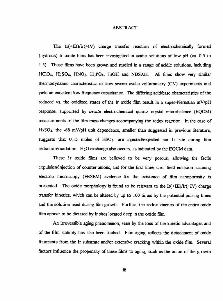
The Ir(-m)Ar(+Iv) charge traa&er readon of electrochemîcaily formed
(hydrous) Ir oxide hlms has been investigated in acidic solutions of low pH (ca 0.5 to
1.5). These f i s have been grown and studied in a range of acidic solutions, including
HCQ, H2SO4 HN03, Hg04, TsOH and NDSAH. Ail films show very similar
themodynamic characteristics in slow sweep cyclic voltammetry (CV) experiments and
yield an excellent Iow fkequency capacitance. The mering acÏd/base characteristics of the
reduced vs. the oxidized states of the Ir oxide film result in a super-Nemth rnV/pH
response, suppoaed by in-& electrochemical quartz crystal microbalance (EQO
measurements of the film m a s changes accornpanying the redox reaction. In the case of
HzS04, the -68 mWpH unit dependence, srnalier than mggesteci in previous literature,
niggests that 0.15 moles of HS04 are injected/expeUed per Ir site during film
reductiodoxidation. Hz0 exchange also occurs, as indicated by the EQCM data.
These Ir oxide films are believed to be very porous, dowhg the facile
expulsion/injection of counter anions, and for the fist time, clear field emission scm-ng
electron microscopy (FESEM) evidence for the existence of tilm nanoporosity is
presented. The oxide morphology is found to be relevant to the Ir(+EI)Ar(+rV) charge
uansfer kinetics, which cm be altered by up to 100 times by the potential puising h e s
and the solution used during film growth. Further, the redox kinetics of the entire oxide
film appear to be dictated by Ir sites located deep in the oxide film
An irreversible aging phenornenon, seen by the loss of the kinetic advantages and
of the film stability has also been studied. Film aging reflects the detachment of oxide
fkqpents f b m the Ir substrate W o r extensive cracking within the oxide film. Severai
fâctors influence the propens* of these films to mg, such as the anion of the growth

and test solutions and the potential b i t s and pulsing times used to grow and study the
films. Film can be prevented dtogether through the selection of the appropriate
conditions for nIm gowth and study.

I would Iike to acknowledge on the assistance which 1 have had fiom the fobwing
indiMduals and institutions; without whom, 1 codd not possibly be presenbng this
dissertation :
Dr. Viola 1. Birss, rny supervisor, for her tirekss support and helptùl discussions
over the past years.
1 am also deeply in debt to Dr. Petr Vanysek of the University of Northern minois,
for his generous access to ac impedance instruments, as weil as Dr. R Davidson and Dr.
M. Wagter fiom SUTface Science Westem, University of Western Ontario, who camed out
the FESEM examinations and to Maria Chen and Tien Phan, who provided the M e r -
coated Ir quartz crystals. Many thanks go to Mr. Manfred Herfort and Ms. Debra
Gladiotis for assisting in the operation of the SEM and XRF instruments in the Faculty of
Medicine and the Department of Geology and Geophysics at the University of Calgary.
Special thanks go to Dr. Shen-Jiang Xia from the University of Calgary for
allowing me to use his software program to evaluate ellipsometric data and helpfùl
discussions with him are greatly appreciared. Financial support fi-om the Department of
Chemistry at the University of Calgary and the Naturd Sciences and E n g h e e ~ g Research
Council of Canada throughout my studies is gratehily acknowledged.
1 am also gatefiil to many other indivïduals in the Department of Chemistry and
other members of our research group, Greta Prihodka, Willi Almonte, Bob Hadlow, Dan
Wehrii, Chn'stoph Taeschler, Grant Carelse, Marco Passofaro,
Dr. Pat Gladstone, Dr. Brian Dyck, Dr. Joe Chau., Howard Jones, Joe Micheau,
Dr. Russel Byme, Dr. Nick Irvine, Jeff Segai, Irina Serbrennikova, Rick Wong, Rong
Yue, Dr. Sharon Thomas and Huyen Dinh for their help and compay.

DEDICATION
Für Dani, Thomas, rneine Eltern
und
Anneliese Schmidt
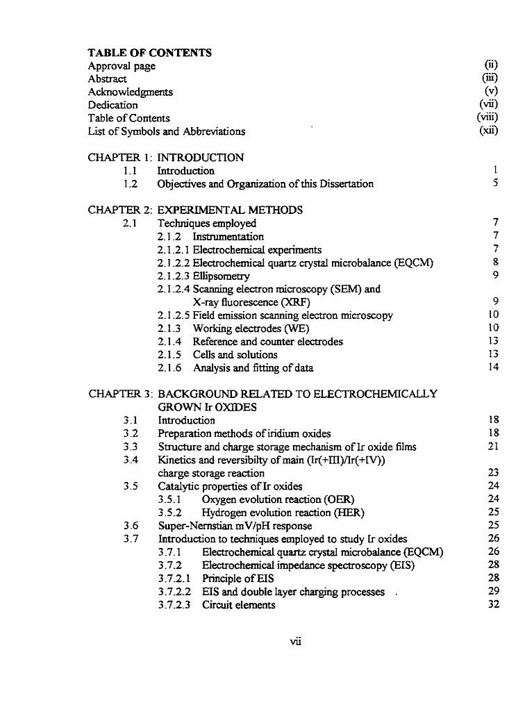
TABLE OF CONTENTS Approvd page Ab~bact Acknowledgnents Dedication Table of Contents List of Symbols and Abbreviations
CHAPTER I : INTRODUCTION 1.1 Introduction 1.2 Objectives and ûrganjzation of this Dissertation
C W T E R 2: EXPEIUMENTAL METHODS 2.1 Techniques employed
2.1 -2 Instrumentation 2.1 -2.1 Electrochemicai experiments 2.1.2.2 Electrochemical quartz crystai microbalance @QC;M) 2.1 -2.3 Ellipsometry 2.1 -2.4 Scanning electron rnicroscupy (SEM) and
X-ray fluorescence (XW) 2.1 -2.5 Field emission scanning electron microscopy 2.1 -3 Working electrodes (WE) 2.1 -4 Reference and counter electrodes 2-1-5 Celfs and solutions 2.1 -6 Analysis and fitting of data
CHAPTER 3: BACKGROUND RELATED TO ELECTROCHEMICALLY GROWN Ir OXZDES
3.1 Introduction 3 -2 Preparation methods of iridium oxides 3.3 Structuremdchargesto~emechanismofIroxidefilms 3 -4 Kinetics and reversibilty of main (Ir(+m)Ar(+N))
charge storage reaction 3.5 Catalytic properties of Ir oxides
3 -5.1 Oxygen evolution reaction (OER) 3.5 -2 Hy drogen evolution reaction (HER)
3 -6 Super-Nenistian rnV/pH response 3 -7 Introduction to techniques employed to study [r oxides
3 -7.1 Electrochemical quartz crysta microbalance (EQCM) 3 -7.2 Electrochemicd impedance spectroscopy (EIS) 3 -7.2.1 Principle of EIS 3.7.2.2 EIS and double layer charging processes - 3 -7-2.3 Circuit elements

CHAPTER 4: OPTTMIZATION OF EXP-TAL CONDITLONS TO GROW Ir OXDE FTLMS
4-1 Introduction 4.2 Seiecbon of the growth solution
4.2.1 Solution composition and concentration range 4.2.2 Electrochemical stabitity of the solutions 4-23 Sunable atids
4.3 Characteristics of CVs in diffèrent acïdic solutions 4.3.1 The Al and C t peak half-widths 4.3 -2 CV peak potentials
4.4 E+g and Ep values during oxide gowth 4.5 Summary and Conclusions
CH4PTER 5: THE mVlpH DEPENDENCE OF ELECTROCHEMICALLY FORMED Ir OXIDE I;ILMS
5.1 Introduction 5.2 The rnVlpH response
5.2.1 Themodynamic issues 5.2.2 Prior reported mV/pH responses for Ir oxide films 5-23 Determination of the mV/pH response for Ir oxide films
in solutions of low pH 5.2.4 mV/pH response for Ir oxide films &rom in H2SO4 5 -2.5 Experimental mV/pH respanse of Ir oxide films formed
in different acidic solutions 5.3 Summary and Conclusions
CHAPTER 6: MASS CHPLWGES ACCOMPANYLNG THE E U C T R O C m C A L REACTION OF HYDROUS Ir OXlDES FILMS
6.1 Introduction 6.2 General fkquency response during oxidation/reduction of
Ir olode films in acidic solutions 6.3 The influence of the growth solution on Amred-ox/mol Ir
6.3.1 Only protons and Hz0 involved durhg the Ir(+lII)/Ir(+IV)reaction
6.3.2 Anions are involved during the Ir(+LII)/Y+IV) readon 6.4 The influence of the test solution on the mass change of Ir oxide
films during the Ir(+In)/Ir(+LV) readon 6-41 Overail film mass (fiequency) changes for Ir oxide nIms
oxidizedkeduced in different test solutions

6.4.2 T6e influence of the test solution anion on &-red/m~i Ir 6.4.3 Effect ofpoterrtial qcling vs. puising during oxide growth
6.5 Detded andysis of mass to mole ratio over aarrow poteirtial ranges 6.6 Sulnmary and ConclusÏons
EIS CEI[ARACTERlZATION OF HYDROUS Ir OHDE FILMS Introduction Experimeatal EIS response and the selection of the best-fit equivdent c i r d Analysis of the ac data 7-4.1 Comments to theoretid models used in this research 7.4.2 The hi& fkquency cutoff reg-on 7.4.3 Interfacial processes 7.4.4 Ir oxide supercapacitor 7.4.5 Tme h i t e d transport withui the film Summary and ConcIusÏons
CKAPTER 8: THE EFFEET OF THE W W T H CONDITIONS ON THE PROPERTES OF THE Ir OMDE F'ILMS
8.1 Introduction 5.2 Experimental 8 -3 CV studies of Ir oxide films grown using Werent
tE+g and tE-g values 8.4 EIS determination of the kinetics of Ir oxide films grown
and studied in TsOH 8 -4.1 Nyquist plot characteristics 8.4.2 EQC anaiysis of the semi*-idnite transport element, CP& 8.4.3 Dependence of oQ on EdC
8.5 Growth me of Ir oxide films in 0.3 M TsOH using Merent potentiai pulsing times
8 -6 SEM characterization of fr oxide films 8.7 Ellipsometric studies of the effect of Etg and tE-g on Ir oxide
film properties 8.8 FESEM studies of Ir olade films 8.9 Summary and Conclusions
CHAPTER 9: KZNETICS OF THE Ir(+nI)/Y+IV) REACTION RATE [N
DIFFERENT ACIDIC TEST SOLUTIONS 9.1 Introduction 9.2 Experimental 9.3 Data treatment 9.4 Ir oxide h s studied in acidic solutions of different composition
9.4.1 CV characteristics

9.4.2 EIS response of Ir oxide films grown and studied in H3PO4 9.4.3 The EIS response of Ir oxide films grown in &Po4
and then shidied in 0.16 H2S04 9.4.3.1 Cychg between 1.2 V and -0.3 V 9.4.3 -2 Cycling in restrÏcted potentiai window 9.4.3.3 Ir oxide fiIm Ieft at the OCP in H2S04
9.5 Ir aide fiIms grown in 0.16 M H2S04 and then tested in 2 M HjPOj
9.6 Influence of the test solution concentration on the kuietics of Ir oxide fh
9.7 Summary and Conclusions
CHAPTER IO: IRREVERSELE DIMINISHMENT OF THE Ir(-UI)/Ji(+IVl CHARGE TRANSFER KIXETICS (FILM AGING)
10.1 Introduction 10 -2 Irreversible aging of Ir oxide films 10.3 Experimental detads 10.4 Generd characteristics of irreversib1e Ir a i d e film agïng
10-4.1 Ellipsometry of mageci vs. aged Ir oxlde films 10.4.2 Scanninç Electron Microscopy of unaged vs. aged h s 10.4.3 Growth of additional oxide in the presence of aged film
10.5 EIectrochemical Impedance Spectroscopy of unaged vs. aged f i s 10.6 Effect of Ir oxide gowth conditions on fiIm @ng
10.6.1 Minimum film charge d e n e required to age a film in a range of acidic solutions
10.6.2 Effect of tE-+g and tE-s on the propensity of Ir oxide film aging
1 0.7 Effect of conditions employed after Ir oxide film growth on susceptibility to agirtg 10.7. 1 The sweep rate used after oxide growth 10.7.1 .1 Ir oxide fiIm grown in HCQ IO .7.1.2Ir oxide f k s grown in H N 0 3 10.7.2 The 'critical potenihi cyding limits' used afler growth 10.7.3 The oxygen reducbon reaction (ORR) 10.7.4 Effect of the test soIution anion on Ir oxide film agkg 10.7.5 Aging prevention d e r film growth 10-7.6 Effect of solution agitation on Ir oxide fibn aghg
and on the oxide kinetics 10.8 Summary and Condusions

CHAPTER 1 1 : CONCLUSIONS Am SUGGESTED FUTURE WoRK 1 t . 1 Conclusions 1 1.2 Recommended Future Research
LITERATURE

LIST OF SYMBOLS AND ABBREViATIONS
1. A A- A0 AI Al'
AC-S. A-rate ac C Co ci C(&Y 1 CE CPE CV C
D d di dc E
E0 E(1/2) EC El S EQC EQCM F FESEM. f HER h I
10
9) int
J K
Roman letters area of electrodes [cm2] univda anion anodic prepeak anodic @(+III) to Ir(+IV)) CV peak Ir(-m) to Ir(+TV)) CV peak for syed films at fàst sweep rates (see Chapter 1 O) American Chemicd Society rate of film Wg, as dehed in Chapter 10 dtemating niment capacitance @?l cathodic post peak cathodic @(+IV) to Ir(-III) CV peak covariance counter electrode constant phase element c y c k voltammetry or cyclic voltammogram concentration [moi cm" 1 difision coefficient [cm s- ' ] thickness of film [cm] characteristic transport pathway, as discussed in Chapter 3 [cm] direct current potentid M, usually refers to the potential of the working the reference elmode standard redox potential peak M-width at peak ha-height, as dehed in Chapter 4 electrochromic display materials
electrochemicai crystal microbalance Faraday constant, 96485 [C mol-L]
hydrogen evolution r d o n hi& as defined in Chapter 6 m e n t [A]
*
exchange current density at zero overpotential [cl&] CV peak current [A] intermediate, as defined in Chapter 6 fi proportionaiity constant, see Eq. (3 -5)

ext-nction coefficient low, as defined in Chapter 6 r-ve index number of eIectrons phase eIement factor for a CPE overtone number open-circuit potentid oxygen evoIution reaction oxygen reduction reaction dectncal charge [Cl equilibrïun film charge densir): as defined in Chapter 4 [ I T I C / C ~ ~ ]
resistance [ohm] gas constant, Le., 8.3 14 [J mol' K-'1 - correlation fkctor Fresnel coefficient of paralle1 polanzation to the plane of incidence, see Eq. (3.20) Fresnel coefficient of perpendicular polarkation to the plane of incidence: see Eq. (3.21) reversïble hydrogen eIectrode root mean square scanning electron microscopy standard hydrogen electrode sputtered Ir oxide f i s sodium saturateci calomel electrode temperature w] transmission Iine working electrode transference nwnber pulsing tirne a- E+g used to grow Ir oxÏde film pulsing time at E-g used to grow Ir oxide film individual variance X-ray photoelectron spectroscopy X-ray fluorescence spectroscopy impedance [ohm] real impedance [ohm] haghary impedance [ohm] ionic charge
Greek letters interad-on parameter reIated to E, see Eq . (3.13) fraction of sites that are in the Ir(W state, as defined in Chapter 4 chi-squared error, see Eq. (3.1 5) fiaction of redox sites that are reduced

measured change in phase SM in eiIipsometry, see Chapter 3 SM in resowit fiequency wz], see Eq. (3 -5) mass change [pg], see Eq. (3.5) relative residud of the red impedance of the ib data set, see Eq. (3.13)
It
hapinary II ", see Eq. (3.14)
interaction energy between redox sites [J mol-'] angle of incidence angle of refkaction overpotentd [VI volume tiadion of component 1, see Eq. (3 -23) volume fraction of component 2, see Eq. (3 -23) penetration depth of ac signal [cm]
-1 -2 shear modulus ofthe osciiiator (2.947 IO-* ' g cm s ) sweep rate [mV SI] function of 2, see Eq. (3.1 1) d e n e of the quartz oscillator (2.648 g cmJ) frequency independent red constam related to ZCPE, see Eq. (3.8) time constant [s], see Eq. (10.3) radian fiequency [s-'], see ~ q . (3 -9) characteristic fiequency for dl charging process [SI], see Eq. (3.7) frequency [s-'1 related to oc, see Eq. (3.6) transition kquency [s" 1, characterizing the change from semi-inhite to
transport conditions for wiiform transport processes, see Chapter 3 transition kequency [s-'1, characterizkg the change fiom partly resistive- capacitive to mainly capacitive behavior for non-uniform transport processes, see Chapter 7 mamition fiequency [s"], characterizkg the change from mainly capacitive to ideally capacitive behavior for n o n - d o m transport processes, see Chapter 7 transition frequency [s-'1, characterizhg the dope change between two partly resistive-capacitive TMLs, see Chapter 10 measured change in amplitude in ellipsometxy, see Chapter 3
Su bscripts apparent charge transfer double layer electron s effective equilibrium

species i Low fiequency go* oxidized sites (Le., Ir(+IV)) reduced sites (Le., Ir(+III)) soIutlon supercapacitor transport
other symbols and abbreviations
cornplex quarrtity U P P fower degee of film aging, as defined in Chapter L O atomic hydrogen adsorptioddesorption reaction

CHAPTER 1
INTRODUCTION
1-1 Introduction
Electroactive d a c e films which yield a revemile change in film oxidation state
and can be fomed to a wide range of thicknesses are of geat interest due to their promise
in a variety of applications, e.g., in energy starage devices [I,2], electrochromic materials
[3,4], and as interneural stimulating electrodes [5]. One major class of these types of
surface materials include oxïde films which forrn on certain transition metai substrates,
e-g., Ir, Ru, Co, Nb W and several others [1-51. These oxides are ofken generated
electrochemically by poiarizïng the potential of the metal between specific limits or by
themial decomposition of a metai salt (e-g., IrC13) [1,6]. They are &en hydrous
materiah, and their useful electr~che~cal response arises h m a rapid and reversible
change Ui the oledation state of the metal sites w i t . these films which rrquires charge
compensahg counterïons in the reaction. An example of such a reaction is [ I l :
Another type of a m material which fdls into this broad category involves certain polymer
films [2], e g , polyaniline, polypymole, etc. The electrochemical activty arises fkom
oxidaîiudreduction of the polymer itseE again with the need for solution ions to be
injected and expelled to mintain electroneutrality withu> the film matenal.
The electrochemical conversion of certain electroactive surface films can yield high
pseudocapacitive charges, which increase with the number of redox sites converteci and
hence with the film thickness of a particular materid. This is cont rq to the case of

passive dielectnc materiais, for which the capacitance decreases with the 6im thickness.
At the present time, the energy storage densities of such electroactive Surface films, which
belong to the dass of electrochemid capacitors [q, range between 1 and 5 Wh kg-' [g],
Le., they £ili the gap between batteries and double layer capacitors. However, these
electroactive suf ice film are ofhigher power density and longer cycte lifetime than most
batteries, since no rate and Lifetime determining phase transformations take place.
Conductive polymers are economically attractive materiais, although their capacity per
rnass, which is maller than 500 C 8'. is low [8] cornpared to hydrous odde films f m e d
on noble metais. Both the oxïdes of Ru and Ir are of interest as electruchemicai
capacitors. The advantage of Ru oxide includes the large heterogeneity of the redox sites,
thus resultins in a broad voltage range over which an almost ided capacitive behavior is
seen, as well as a hi& power density [9], whereas the voltage range of Ir oxide is more
narrow. However, ir oxides are generally more hydrous in nature, thus yiefdiug a larger
low fiequency ac capacitance, equivaient to an increase in capacity per mass [IO].
Burke [I 11 has divided metai oxides into two classes, based on their structural
propedes, compact, anhydrous oxides and hydrous oxides. In both oxide types, oxy-ions
serve as bridgirrg species, although oxygen is aisu present in the fom of termidy
coordinated hydroxy and Hz0 species. This has been supporteci by XPS studies [12],
which showed the presence of at least three different oxygen species (02-, OH- and bound
H20) within hydrous metal oxides, as weU as other solution ions. Hydrous metal oxides
contain a large quantity of unbound H20, as indicated fiom the mud-cracked structures
seen by electron microsmpy 1131, thus suggestuïg a more open structure for hydrous than
compact oades and hence a higher specific charge storage capacity. The degree of
hydration sometimes depends on the film thickness when oxides are generated
electrochemically, Le., thin oxides are generally more compact and, vice versa, thick

oxides are more hydrous in nature [I l ] . The structure of thermally prepared oxïdes are
strongly iduenced by the annealing temperature, precursor material (metal and ion types),
etc. [14,15].
Hydrous oxide fiIms grown electrochenrically on noble rnetals often show "super-
Ne&an" behavior, Le., the mV/pH dependence of the p ~ c i p l e peak seen in the cyclic
voltammetric response is larger than the expeaed -59 mV/pH at 25OC [16,17], which may
indicate that more than one proton or hydroxide ion is injecteci into or expelled fiom the
film per electron passed during the reamion. This behavior has been suggested ta be
related to the stronger hydroxylation of the oxidized vs. the reduced metai sites in these
films [18]. The principle of electroneunality then requires that more than one species
serves as the counter ion during the electrochemid conversion when super-Nemstian
behavior is O bserved. Therefore, in acidic solutions, anions, and in alkaline media, cations,
will also be involved. This, in tum, requires a porous structure of these oxides. In fact,
several hydrous oxides, e.g., Pd and Ni orades, have been shown tu be microdispersive in
nature [19,20], allowing rapid and reversible injection and expulsion of counter ions, as
observeci typically for finely dispened and hydrous or- or y-oxides ofNi vs. the anhydrous
B-state of Ni oxide [2 1 1.
The electrochemical conversion of these eIectroactive surface films is often
accam panied b y a rapid color change, thus making them attractive for electrochromic
display application @Cs) [22,23]. ECs are divided into two classes, depending on the
mechankm of coloration. 'Cathodic coloration' is observeci for materials such as WO3,
V205 and MoO3, and 'anodic coloration' takes place with the oxides of Ir and Ni. Most of
the reversible charge recovery processes with materials of the 'anodic coloration' class
have been reported to take place in aqueous media [Z]. However, a rapid and reversible
insertion mechanism of ~ i - counter ions in non-aqueous solutions is desired, since this

mobile species yields long term electrochemical stabiw at elevated temperatures [3]. As
memioned above, the mechanism of cowiter ion injection is strongly reIated to the
structure of the oxides, Le., highty efficient EC behavior has been reportai for
microcrystalIine materials havhg textures consisting of microcrystallites of less than 50 A in size [3]. However, charge recoves, might be Limaed by the hindered injection of the
counter ion into the film, as typically observed with Li-based transition metal oledes [SI.
The quality of electroactive surfiice films is defined by the kuietics and revemibility
of the charge injeaion/expulsion mechanism (Le., the identity of the counter ions and the
film material microstructure), their stability and lifetime ( e g , the adhesion of the matenai
to the substrate and deterioration of the dernoactive film), the active charge density ( e g ,
degee of hydration and accessicbility of solvent to the redox sites), etc. These properties
are often altered when the materiais are exposed to air or vacuum and therefore, in-situ
techniques should be employai to study these systems. In recent years, electrochemical
quartz crystal microbalance ( E Q W meanirements have attracted much interest; this
approach allows the in-sifu meanirement of the rnass change accompanyirg an
electrochemicd conversion process [24,25]. Electrochemical impedance spectroscopy
(EIS) has aiso been applied widely to these materials, offen to gain mechanistic transport
information [26-291. Some effort has aiso been made to extract structural information
about these materiais fiom the EIS data [30]. However, the cornplex nature and variety of
the processes occurring within these materials makes interpretation d E d t , in facf often
rather meaningless. Ellipsometry and reflectometry have been successnilly employed to
study the mechanism and the kinetics of colorationidecoloration reactions [3 1-33].
I.lr-siru techniques such as XPS, X-ray diilkaion, etc., have &O been employed [34-361
to probe the composition and structure of oxides on metals, despite the structurai changes
which might be introduced by removal of the films fiom the solution.

in recent years, aîomic force and sceng tunneling microscopy [37] tave also
becorne of interest since they have the potentid to yield in-situ structural mformation at
nanometer resolution However, the sufiaces of these materials are &en quite r o u a
thus making the applicabiiity of the latter two techniques rather doubt5.d.
Despite the substantid arnount of research which has been camed out on these
systerns to date, many uncertainties regarding the oxidation/reduction mechanism and
other propemes of these materiais still remain. Also, most of the investigations of
electrochemically generated hydrous metal oxides have been perfomied in aqueous media,
sometimes investigating pH effects on the electrochemical performance. Little is hown
about the effects of other ions of the growth and test solutions, as well as the influence of
other growth conditions, on the kinetics and stability of these oxide film materials.
1.2 Objectives and Oqanization of this Dissertation
In the present work, hydrous Ir oxide films, referred to simply as Tr oxide films' in
this dissertatioq fonned electmchemically on polycrystalline Ir meral substrates, have been
snidied in a range of acidic solutions using a variety of electrochemical and non-
electrochemical techniques. Electrochernically grown hy drous Ir oxides have been found
to exhibit a super-Nemstian mV/pH response, rapid oxidation and reduction kinetics of
the principal Ir(im)/lr(+IV) charge storage reaction, and generally show superior
chernical and physical stability over a large number of oxidation/reduction cycles
performed in a broad range of solutions [38-401.
Chapters 2 and 3 oveMew the methods used in this work and the prior literature
related to Ir oxides, respectively. Chapter 4 discusses the appropriate conditions to use
for the growth and the investigation of hydrous Ir oxide films carrieci out in order to gain
insight into the charge transfer reaction, the expulsion/ujection of counter ions firom/into

these films during the Er(+ïiI)/Ir(-IV) oxidationlreduction readon, etc- Characteristic
cyclic voltammetric (CV) features of Ir oxide films grown and mdied in a range of acidic
soIutions, including some never investigated previousJy, are discussed in Chapter 4.
Aspects of the charge expulsion/injection process associated with the Ir(tllI)/ir(+IV)
oxidationkeduction reaction are presented in Chapters 5 to 1 O, with a focus on identifjing
the species serving as the counter ions and their influence on both the kinetics and physicai
stability of hydrous Ir oxide &S. Chapters 7 and 8 of this dissertation cover the results
of studies of the conditions of growth on the oxide properties, in particdar the effect of
different anions of the growth solution as weII as the infiuence of the anodic and cathodic
potentid pdsing times, used during growth, on the kinetics of the Ir(+OI)/Ir(+IV)
conversion reaction. Factors such as the oxide fiim thiclcness and rnorphology which rnay
be responsible for the experimentaiiy observed kinetic ciifferences, are dso discussed in
Chapters 6 and 7. Also, the nature, oriçin and prevention of an irrevenible diniinishrnent
of the kjnetics of the Ir(+lII)îir(+iV) conversion reacüon, whkh wilI be shown to be
related to an irreversible decrease in f lm stabiiity, is examineci in Chapter IO. Chapter 1 I
sunimarizes dl of the results obtained and suggests research which s h d d be canied out in
the future to gain M e r insight into these systems.

2.1 Techniques employed
Al1 of the electrochemicai experiments in this work were performed in aqueous
solutions utilinng a standard three electrode configuration. The electrochemicai rnethods
employed can be classifieci into two categories: (1) hear sweep methods mich as cyciic
voltammetry (CV) or constant potential polarization; (2) electr~che~cd impedance
spectroscopy (EIS), which invoIves the superposition of a midl sinusuidal potential
pemirbation on a dc bias potential. Electrochemical methods of the first category were
aiso combined with quartz crystal microbalance (EQCM) measurements and eiiipsometry.
2 1 Instrumentation
2.1.1.1 Electrochemid experirnents
Most of the iinear electrochernical experirnents were carried out using a
Jaissle potentiostat/gaivanostat IMP 83 and an EG&G Parc 175 fcunction generator (Fig
2.1). Occasionally, an EG&G 273 potentiostatlgdvanostaf interfaced to a Sarnsung SD
630 PC and dnvem by 'echem software' (EG&G Parc), was employed to carry out slow
sweep experiments (< 1 mV/s). A BBC Goerz Metrawatt SE 780 an4 occasiondy, a HP
7044B X;Y recorder, were employed to record the CVs, ment-time response, etc.
A Solartron Schlumberger 1255 HF fkequency response analyzer and a Solartron
Schlumberger 1286 electrochemical intefice were utilized for the EIS measurements. An
IBM 8088 PC, whch was driven by ZPlot 1.6 software (Scribner Associates, Inc.), was
interfaced tu the Solartron systern and serveci as a data acquisition system for EIS
measurements. A sinusoidd excitation signal of 5 mV RMS ampiitude was found to b e

sufficiedy smdl to yield a linear response for the systems i n ~ ~ g a t e d by ac impedance in
ui is work Frequencies below 100 kHz were studied and eaher 12 or 1 O points per decade
were collecteci. The resistor used for the m e n t measurements was set to 'auto'. A h , a
slow auto integraton mode of the kequency analyzer and a C bandwidth of the
potentiostat were found to be appropriate for the measurements performed in this
researc h .
Figure 2.1 Inmental set-up employed for elecnochemical measurements.
Electrochemicai quartz crystal microbalance (EQCM)
The EQCM system was utüized to rneasure the oxide film mass changes by
monitoring srna1 changes in the resonance fkquency of quartz crystal osdator (Fig. 2.1).
The oscillator (M. Bertram, Department of Geology and Geophysics, University of
Calgary) was powered by a 3 V dc source and the crystal fkequency changes were tracked
by a Pmpps PM 6654C hi& resolution fiquency tirner/counter. A resolution of ca 1 to
0.1 M was achieved using integration periods of 1 to 10 S. The frequency changes were
plotted vs. potential on a BBC Goerz Metrawatt SE 780 recorder.
2.l.t.3 Eiiipsornetry
A Gaertner Scientific Corporation ellipsometer (mode1 LI 16C) was
ernployed to monitor the opticai properties of Ir oxide f i s . The eIlipsometer was
Ïnterfâced to a IBM 386 PC, which was driven by Standard Program software (Gaertner
Scientific Corporation). The eilipsometric data was acquired using a red laser beam of
632.8 nm, an ande of incidence of 70' and a poiarizer dnun angIe of 45'. The data
acquisition time was 2 S.
2.1.1.4 Scanning electron microscopy (SEM) and X-ray fluorescence 0
A Cambridge S250 Stereoscan SEM systern (Department of Geology and
Geophysics, University of Caigary) and a Hitachi 100 SEM (FacuIty of Medicine,
University of Calgary) were employed for the SEM and XRF work Most of the samples
were first sputter-coated with a ca 30 nrn Au/Pd layer to reduce beam chargïng effects.
Tiie samples were attached by conducting carbon tape (Electron Microscupy Sciences) to
Al stubs. A KEVEX - 7000 Micro-X was coupled to the Stereoscan S25O system,
allowing qualitative and semi-quantitative XRF analyses to be carried out. The K-a lines
of Cu and Ai were used to cali'brare the XRF systerns and Cu wires partiaily wrapped in Ai
foil were employed as standards. For the SEM and XRF studies, an accelerating voltage
of 15 and 20 kV, respectively, a typicd working distance of 15 mm, as welI as a data
acquisition time of 72 s (the latter for the XRF work) were generally empioyed. A
standard mple, 2160 lines per mm (Faculty of Medicine, University of Calgary), was
u s d for accurate dimensional measurements by the SEM.

2.1.1.5 Field emission scanning electron microscopy (FZSEM)
A Hitachi S-4500 FESEM @r. R Davidson and Dr. MicheHe Wagter,
Surface Science Western, uni ver si^ of Western Ontario) was empbyed to obtain hi@
remlution information about the Ir oxide d a c e morphology. The accelerating voltage
was either 5 or 30 kV and a workmg distance of 5 mm was used.
2-13 Workingelectrodes (WE)
Ir oxide films were grown on polycrystdline Ir metal substrates on either a wire
(generally of 1 mm diameter and 1 cm Iength) or foil (of 0.1 cm thickness). The metais
were purchased from Johnson-iwatthey and were of99.8% puriv. The Ir wire was spot-
welded to a 'TL wire and seded into soft glas tubing exposing o d y the Ir wire, as shown
in Fig 2.2a The foiIs were either spot-welded to an Ir wire electrode (Fig. 2.2a) or (when
utilized for the preparation of XRF, SEM and FESEM samples) were suspended via a
smdl hole in the foi1 by a Au wïre electrode (Fig 2.2b). The latter N e of foil electrode
was wrapped partially with Paranlm to prevent contact of Au with the solution. .41so, the
Au wire was used because of its flexiiil* and chemicai inertness. The foils utilized for
the electrode types is sbown in Fig. 2.2b were ca. 0.3 cm wide and Ca. 0.5 cm long.
For ellipsometric measurements, a disc-shped Ir foil of 0.28 cm' area was
embedded into a Teflon hoider and a copper block was used to establish electn*cal contact
to the Ir working electrode Pig. 2.2~). Before an oxide film was grown on this disc-
shaped substrate, the Ir metal was first poiished ushg 1500 grït emery paper, then
polished with Al powder ofi p particle ske (E.T. Enterprises) and findly rinsed with
deionized and distilleci H20.
Previously grown Ir oxide film was removed before a new oxides was fomed by
utilinng a similar method to that suggested by Pickup and Birss 1411. Altemating

potential pulses, each of 5 s duration, were applied between 1.6 V and 4 . 3 V vs. an SSCE
in 2 M H2SO4, leaving ca 1 monolayer (ca 0.15 r n ~ / c m ~ ) of oxide on the Ir substrate.
The anodic potentd, however, was increased to 1.8 V to achieve removal of oxides
grown in 2 M H m 4 solutions. The time required to remove the oxide was found to
depend prirnady on the solution utilized for film generation. For example, removd of a
film gown in 0.4 M KNO3 required ca. 20 min., whereas films grown in any other acidic
solution employed in this work required between 10 and 15 min.
soft glas tubing
\
Ni wire
soft glass tubmg \
Ni wire
Figure 2-21 Figure 2.2b
Figure 2.2 Schematic of srpical working electrodes used ta grow hydrous Ir oxide
films (not to scale). Fig. 2.2a shows the electrode used for Ir wire substrates, whereas
Fiç. 2.2b shows the same, but for Ir foi1 substrates.

(a) top view
(b) side view
Figure 2 . 1 ~ Schematic of WE used for ellipsornetric experiments (not to scale).
5 h4E-k AT-cut quartz crystals, one inch in diameter and purchased h m Valpey-
Fisher, were employed as the oscillators and working electrodes in the EQCM
experiments. The crystals were sputîer-coated on both sides in the typical keyhole pattern
(see below), first with ca 80 nm Ti layer and then with a ca.. 50 nm Ir layer. Both the Ti
and Ir targets were purchased fkom Johnson-Matthey, both were of 99.99% purity, 1/4
and 1/8 inch., respectively, thick and 2 inches in diameter. A Denton Vaccum DV-502A
System was employed to sputter-coat the crystals in a Argon atmosphere of 4 to 4.5 mm
Hg. The Ti was sputtered in 100 s at a. 0.4 4 whereas the Ir was sputtered for 6.5 min.

at ca 0.1 A Between these coating steps, the crystds were exposed to air for 5 to 10
min. Au wires were attacbed to the edges of the k keyhole-sbped coating on the aystal
with conducting Ag epoxy (2400 Circuit Works kit, distributed by AUied EIectronics) to
provide e1ectrica.i contact.
1 4 Reference and counter electrodes
A sodium chloride satwated calomel reference electrode (SSCE) was generally
employed in this work and ail potentials are referred to d in dns dissertation (0.236 V vs.
the standard hydrogen electrode (SE)). Occasionally, a reversibie hydrogen electrode
(RHE) was employed as the reference electrode.
In ail EIS rneaSuTements, a Pt wire electrode, Iocated in the working electrode
compartment, was shunted by a 5.7 capacitor to the SSCE reference electrode. The
more rapid response of the Pt wire vs. the SSCE improved the q u w of the hi@
fi-equency measwements. A high area Pt mesh electrode served as the counter electrode
(CE) in aII of the electrochemical experiments. AU Pt electrodes were occasionally
cleaned by potentiai cycliq at IO V/s in 2 M H2SO4 between O V and 1.6 V.
2-1-5 Cefls and solutions
Standard two cumpartment dass cells, in which the reference cornpartment was
connected to the WE and CE compartment thruugh a Luggin capillary, were employed to
grow and study the Ir oxide films (Fig. 2.3). The WE cornpartment (Fig. 2.4) utilized in
the EQCM measurements differed in constructibn fiom the standard ceil generally
employed. The quartz crysîai working electrode was sandwiched between the open-
ended, circular base of the working cornparmient of the EQCM cell and a g.lass tube, as
s h o w in Fig. 2.4. Two rubber O-rings were placed between the crystd and the two &s

interfaces to prevent leakage of the solution, and a bail and socket clamp (no. 28, VWR
Scientific) was used to hold the two compartnients of the base together.
The conçtniaion of the workmg cornpartment employed for the ellipsometnc
measurements was quite different, as shown ni Fig. 2.5. This ce11 was made of
plexiglassTM and the WE (Fig. 2.2b) entered the cell through its base. A circular 1 cm
diameter glas windows, through which the laser ligbt passed, were Iocated on opposite
wdls of the ce& angleci at 70' relative to the base plare. The holes in one of the remaininç
ceU walIs aiiowed entq of the CE and a gas bubbler into the solution without disturbiq
the passage of the Iight beam (Kg. 2.5).
W chernicals used in this work were A.C.S. anaiyticd grade. The water was
deionized and distilleci using a Coming MEGA-Pure MPdA system and had an
approximate resistivity of 18 Mohm. The solutions for the electrochemical measurements
were generdiy deoxygenated using high purity nitrogen gas and al1 experiments were
camed out at r o m temperature, Le., 20 +/- 2 OC.
2.1.6 Analysis and fitting of data
The EIS data were analyzed and fitted using a non-Iinear least squares fining
software program (Equivaient Circuit, version 3-97), wrÏtten by B. A Boukamp of the
Univers@ of Twente. This program also dlowed testing the of ac data for the Kronig
Kramer transformation. A software program ( E i p s ) , written by Dr. S. Xia (Cinversity of
Calgary), was used to analyze the eilipsometric data

/ top view of cell cap
cell cap f i
Figure 2.3 Electrochemical ce11 employed to grow and study Ir oxide films.

main cornpartment of ceIl
open-ended g l a s tube
Figure 2.4a Figure 2.4b
Figure 2.4 Ce11 ernployed for EQCM measurernents. Fig. 2.4a shows the side view of
the main cornpartment, whereas the top view of the WE is seen in Fig. 2.4b.

(a) top view
(b) side vicw
holcs for d m c s , ctc.
Cc) bavc vicw
for WE
Figure 23 Ceii used for ellipsometric measurernents

CHAPTER 3
BAClKCROWD RELATED TO ELECTROCHEMICALLY GROWN Ir OXIDES
3.1 Introduction
Iridium has been named after the Greek goddess Iris, whose sign is the rai-nbow,
due to the many colors of the Ir compounds. This rare metal is formd dong with other
noble metals of the Pt group in Alaska and South Atn'ca and is obtaind Like Rb, Ru and
Os, nom the residue after Ag Au and other Pt rnetals have been recovered. The uses of
this precious metal are special due to its scarcity. However, the extreme chernical
resistance of this metal, as well as the fâct that Ir is very hard, d e s Î t used preferably for
instrument pivots. Ir and its compounds, often mked with other transition metals, are also
employed as catalysts for methmol oxidation [42] and as a promising cataiyst for the
oxygen reduction reaction (ORR) when doped with Pb [43].
This Chapter reviews some of the relevant characteristics of elecmc~chemically
Jrown hydrous Ir oxide films, includinç the reported growth mechanism and mcture: as
weil as its catalytic propehes towards the oxygen and hydrogen evolution reactions (OER
and Hm). Several different classes of indium oxides, as weU as related transition metal
oxides, wili be referred to briefly. Also, the t h e main techniques employed in this work,
i.e., mass measurements using the electrochemical quartz crystal technique
(EQCM), electrochemical impedance spectroscopy (EIS) and ellipsometry, will be
introduced in this Chapter.
3.2 Ir oxide preparation methods
One preparation method of Ir oxide films is by the thermal decomposition of Ir
salts, e g , IrCl3, on a metal substrate [44,45]. For these oxides, the charge obtahed in a

cyclic voltammetric (CV) scan is known to decrease inversely with the temperature [IO].
Also, the electrochemicai conversion process is not as reversible and the charge capacity
per mass is lower than for flms of sirnilar tbickness fixmed electrochemically. This has
been ascn-bed to the fm that thermally prepared Ir oxide nIms are l e s hydrous, their
water content decreases inversely with the temperature appIied dmhg the Ir salt
decomposition step [IO]. However, some of the inactive sites of the thermaiiy prepared
oxides cm be activateci by the application of cathodic potential pulses, perhaps suggesting
that these sites can be made more accessible to H2O. Ir oxide films can aiso be prepared
by reactive sputteriry of Ir in an oxidizing atmosphere (SIROF) [46-481. This merhod
yields an almost ideal capacaive CV response (constant curent as a h c t i o n of the
potential), although the active surface area to volume ratios are low. This is due to the
faa that oxides prepared by these methods are compact and anhydrous, thus yielding a
surface capacitance, whereas hydrous Ir oxide films show both a bulk (film) and surface
capacitance.
Hydrous iridium oxide films can be fonned e l ~ c h e m m 3 c a l l y by either cycling or
pulsing the potential of an Ir metal substrate, which is imersed in an aqueous solution,
between specific Iimits, ie., to sufficiently cathodic potentials (at leas -0.2 V vs. rhe RHE
in 0.5 M H2SO4) [16,41,49] and to an anodic potentÎal which results in the evolution of
0 2 [38,39]. During the first few growth cycles, a compact oxide film is formed by the
place exchange mechanism [ I 1,411, which results in a broad CV shape [41,50]. A few
monolayers of this compact oxide are formed before additional cychg results in the omet
of the fornation of the hydrous oxide film, for which the nIm charge increases with the
number of cycles, as discussed in Chapter 1. A typicai family of CVs for hydrous Ir oxides
gown in 0.5 M H2SO4 for various times is shown in Fig. 3.1. It is unknown whether the
compact oxide, often assumeci to be Ir02 [4 1,s 1,521, is tùlly corwerted to the hydrous film

material once thick and hydrous oxide flms are fomed or whether a compact oxide hyer
remains between the Ir metai substrate and the ovedying hydrous oxide fiùn
-0.4 0.0 0.4 0.8 1.2
Potential vs. SSCE [Vj
Figure 3.1 Typical family of CVs during gowth of hydrous Ir oxide by cycling in
0.5 M H2S04 at 100 mV/s between 1.2 V and -0.3 V. (-) cycle 3 40,
=le U 80, (---.----- ( - - - )~y ) cycle # 120
The large, symmetrical peaks? Al and Cl, in the CV (Fig. 3.1) are asmcbed to the
el&ochemicd conversion of Ir(+m)/Ir(+IV) sites within the oxide mm. This assignment
has been supported by XPS studies [12?34], which showed the presence of trivalent and
tetravdent Ir species. The hydrous oxide (unlike the compact oxide) c a ~ o t be reduced
back to rnetallic Ir [34]. in facf removal of these oxides can be achieved only by oxidizing

the film sites to the Ir(-VI) -te, preferably in strong acid solutions (eg, 2 M &S04)
[13,41]. The reduced Ir(+IQ oxide fiIm is an insulator and colorless, whereas the
oxidized Ir(4V) oxide film is highly conductive and colored @lue-black) [48,53,54].
Films of up to several .n in thickness can be gowq resulting in a large nwnber of redox
sites which undergo the reversjble Ir(+UI)/lk(+IV) faradaic reaction [ S I .
To achieve continuou fiùn growth, the oxide &as to be dternatingly oxidized and
reduced [ 16,3 8,40,48]. Pickup and Birss found thaf during one oxidation/reduction
cycle, no more than one monolayer of new hydrous Ir aide can be fomed [4 11. They
ascribed this to a larçe IR drop across the outer layer of the k(+rv> fom of the compact
film thus h h d e ~ g further hydrous film growth. This surface monolayer is incorporated
into the bulk hydrous film during the reduction to w); negative potentials are needed
to free the underlying Ir metal for gowth of more hydrous oxide during the next oxidation
cycle. They dso showed [13] that the anodic charge passed up to 0.92 V vs. SSCE under
equilibriurn conditions in 0.5 M H2S04 corresponds to one electron per Ir site in the oxide
and that a charge density of 1 rnc/cm2 appears to be quivalent to a 'dry' film thickness of
16 nm.
lt should be noted that films cannot be grown in aikaline solutions, due to the
dissolution of I r 0 2 [56]. Also, film p w t h is inhibited in HF and HCI solutions, which is
ascribed to the fmat ion of stable hdogenic compounds [57,5 81. However, growth in
neutral, aqueous solutions such as LiC104 poses no problems [59].
3.3 Structure and charge starage mecbanism of ïr oxide f m s
X-ray diflfiaction studies have suggested that electrochemicaiiy gown hydrous Ir
oxide films are amorphous in nature. The 'wet' state of Ir oxide is viewed as consisting of
two phases, Le., a polymiclear backbone containhg Ir(+iII)/Ir(+IV) centers, and the pore

solution [60]. This is based on the very hydrous nature of these films [13,61] and the
suggested involvement of large counter ions during the electrochemicai converrion
process [62]. Ako, the fact that a film thickness independent pseudocapacitance, which is
asaibed to hydrogen atom adsorptioddesorption on the underlying oxide-fiee Ir
substrate, is observed in the CV response (F'ig. 3.1) at potentïds when the nIm itseif is
non-conducting suggests that these nIms are porous in nature [63]. However, this
porosity has been believed ta be on the nanometer scale, since, until this work, SEM
methods have not resoived the fiim porosity [13].
The hydrogen atom adsorptioddesorption pseudocapacitance peaks d o w the
calculation of the real mfhce a m of the oxide-free Ir substrate? assuming that this
process involves a pseudocapacitive charge of 0.21 rnc/cm2 [40,63]. Podlovchenko et ai.
[64] deposited Ag on Ir oxide covered electrodes and found a decrease in the hydrogen
atom adsorptioddesorption capacitance, thus yielding M e r evidence for a porous film
structure andhr the existence of large cracks between oxide patches. However, it should
be noted that they did not establish conchisively whether the Ag was deposited on the Ir
oxiddsolution or on the Ir substratdfih interface-
Several workers [12,33] have suggested that, during the oxidation of ir(+III) tu
Ir(+N) in acidic solutions, more than one proton per electron is expelled h m the Ir oxide
film. This has been ascribed to the fact that the higher valence fiIm (i-e., the Ir(+IV) state)
tends to be more acidic, i-e., prone to hydrolysis, as follows [18]:
Eq. (3.1)

This requires additional counter ion involvement, to preserve electroneutraiity within the
film The presence of d a t e or bisuifàte within hydrous Ir oxide films grown in H2S04
has been confirmed 5y XPS studies [34]. I t was also suggested that the &te in the film
is unbound and does not serve as a bridging ligand [34].
3.4 Kinetics and reversibüity of the main (ïr(+iIï)Ar(+Iv)) charge storage
reaction
The complete film charge of eiectrochemically fomed Ir oxides can be recovered
when the potential is cycled at rates lower than the equilibrium sweep rate (vq) [59]. The
CV peak currents of the main charge storage reaction are then proportional to the sweep
rate [18]. This is referred to as 'thin film behavior', indicathg that sufficient time is
allowed for every film site to be oxidizedlreduced. At sweep rates larger than vq, not
evev site cm reaq which results in an observed ca. 0.5 power dependence of the anodic
peak currents on v [18,59].
The oxidatiordreducti-on kinetics of Ir oxide nIms are rapid. For example a time of
40 rns was found to suffice for the complete coloration/decoIoratioo of ca 20 mc/cm2
films gown in 0.5 M H2SO4, which is similar to hydrous Rh oxide films which, however,
show a less satisfaaory visuai wntrast ratio [65]. Botb the reversibility and the rapid
kinetics of the Ir oxide films are ascriied to the hydrous and probably h i a y porous
character of these films, which is supported by the fact that these properties are markedy
poorer for SROFs [47l and unactivated therrndy prepared Ir oxide films [Ml.

3.5 Ca-c properties of Ir osides
3.5.1 Orygen evolution reaction (O=)
Ir oxide is of geat interest as a potential catalyst for the OER due to its low
overpotential (q) for this reaction [67-721. Ody a few materials exhibit a iower
overpotentiaI and these are Ru oxide and mixed oxides of Ir and Ru [73]. Two Tafel
slopes, Le., 40 mV per decade at low q's and 120 rnV per decade at hi& q's, are observed
for electrochem*cally generated Ir oxide films in acide as wefl as in basic solutions. The
reaction mechanism at lower q's appears to be independent of the electrolyte solution and
the 'electrochemical oxide' path (Eqs. 3.2.a to 3.2.c) has been suggested for the OER at Ir
oxide f h s g o w n and studied in HCQ, H2SO4, H3PO4 or KOH solutions [67-691:
Eq. (3.2.a)
Eq. (3.2.b)
Eq. (3.2.c)
The OER is beiieved to take place at internai ir sites w i t h the open structure of a three-
dimensional oxide, since larger curent densities are observed on hydrous vs. unactivated
themally prepared Ir oxide films [70,71].
High eiectronic conductivities, good stability to corrosion and an appropriate
surface affinity are required for good electrocatalyhc perfîformance [74]. The FdCE that the
conversion of Ir(+lII) to Ir(+IV) is accompanied by a siguficant incfease in the
conductivity of the oxide improves the potential applications of hydrous Ir oxides films as
electrocatalysts for the OER.

3.5.2 Eydrogen evolution reaction @CR)
The overpotentiai of the HER on Ir oxides is not as low as found for other
matenals, e.g., Pt [75] and mixed Ir-Ru oxides [76]. Unlike the OER, the HER appears to
take place at the oxïde-&ee substrate/fïim interface. This is consistent with the insulating
character of Ir(-ïü) oxide, as weii as the decrease of the pseudocapacithe charge due to
the hydrogen atorn adsorption/desorption reaction observed for oxide-fiee vs. oxide-
covered Ir, and the independence of this charge on the fiim thickness [40,63]. Up to four
different peaks can be observed in the CV due to the adsorption and desorption of H
species at Ir [40]. The appearance of these peaks is found to depend on the nature of the
anion and the concentration of the soIution used to çrow and study the oxide, thus
suggesting competitive adsorption between anions and H species and probably lateral
anion interactions with IrH surfàce dipoles [40].
3.6 Super-Nernstian mV/pEI response
The Ir(+IU)/Ir(+N) reaction of electrochemicaily gown, hydrous Ir oxide films is
'super-Nemstian' in nature, meaning that the mV/pH response a p p n to be greater than
-59 at 25 OC [I8]. This contrasts with the Nemstian response ofien observed for compact
metai oxide systems [77], SIROFs [471, etc. Anions (in acid) and cations (in base) are,
therefore, required as charge compensating counter ions during the eIectrochemica1
conversion of hydrouç Ir oxides. This has been investigated for several electrolytes by
analyzing the ionic content of the reduced vs. the oxidized &tes of these film. Pickup
and Birss related the F, OH, K+, ~ i + and Hf content to the experimentaiiy observed
mV/pH response of these oxides in a range of solutions [62]. They suggested the

McIntyre et ai. [77 used Rutherford backscatterïng spectroscopy combined wah
nuclear readon analysis techniques and suggested thaî, in organic sohems such as
propylene carbonate, ~ i + , ~a and F, but not K-, penetrate these films. Birss et al. [78]
utilized EQCM to study the in-situ net m a s change of films in H2S04 and KOH and
suggested that HS04' and K+ ions are involved during the Ir(+m)/Ir(+lV) conversion
reaaion in these two solutions, respectively. They also proposed that water is injected
during the reduction process, and vice versa, dunng film oxidation
3.7 introduction to techniques employed to study Ir oxide fdms
3.7.1 Elcctrochemical quartz crystai microbdance (EQCM)
EQCM rneasurements have been utilized ta investigate the injectiodejecûon
mechanism of conducting polymers [8] and oxjdes fonned on noble metals [25,78], as well
as for many other electrochemicai sUTface studies. Its advantages are its sensinvity
(10 n g h 2 are detectable [24]) and the faa that in-silu measluernents of net mass
changes cm be perfomed during faradaic conversion reactions.

The mkrobalance consists of a piezoeiectric quartz qstd on which thin layers of
metals, the electrodes, are evaporated on both sides, in a keyhole pattern (Fiç. 2.3). An
applied potential across the electrodes induces an oscillating electric field which introduces
a mechanical shear oscilIation in the crystai. The resonant oscillation fkequency of the
crystal depends on the mass of the attached material, Le., the metal, films formed on the
metal, etc. A change in the mass of rnateriaI on the surface of the crystal (Am) results in a
shift of the resonant frequency (Af), as described by the Sauerbrey equation [79]:
Eq. (3 - 5 ) shows that an increase in mass per unit area oscillating ( M A ) resdts k a
propomonal decrease in fkequency by AJ The other parameters in this equabon are
included in the proportionahty constant (K), which is characteristic for the type of
osdator, since it contains the oscillation fiequency of the fundamentai mode of the quartz
cvstal Cfo), the overtone number (no), the densisr of the quartz oscillator (pq) and the
shear modulus of the oscillator (&)- However, the application of the Sauerbrey equation
(Eq. (3 -5)) is M e d to thin and rigid films. Therefore, non-unifonnities within the film,
surface roughness, etc., may not d o w the application of Eq. (3.5) to convert frequency
changes into mass differences.

3.7.2 Eïectrochemicai impedance spectroscopy (EIS)
3-7.2.1 Principles of EIS
In ETS, a sinusoidal potential si& is applied to the system of interest and
the ment magnitude and phase ange (angle between the potentiai and m t vectors)
are then measured as a firnction of the Frequency [80]. Ohm's iaw is frequency
independent and therefore, the current and voltage are related to the complex impedance
(2) in ohms. The current magnitude and phase angie depend on the naaire of the system.
For example, for an ideai resistor, the current and potentiai are in phase (phase ande is
zero), whereas the curent Ieads the potentiai by 90' when an ideal (nonlossy) capacitor is
studied [80]. Obtaining the nirrents magnitude and phase =@es over a range of
fiequencies dlows the assignment of an Equivalent Circuit (EQC), which consisting of
passive electrical elements such as resistors, capacitorç, etc., to a system. The ac response
( m e n t magnitude and phase angie) is observai to be kequency dependenf and also
depends on the magnitude and nature of the EQC elements (see below).
3.7.2.2 EIS and double layer cbarging processes
EIS has been frequentiy appIied to study rn&erials similar to hydrous Ir
olade films, in which sites undergo a fâradaic reaction accompanied by the
injectiodexpdsion of solution ions. Despite many efforts, a complete understanding of
the charge injectiodejection mechanism of these materials has not been gained, partiy
since information about the nmber and type of mobile species involved in the reaction is
not easily extractable. This is mostly due to the non-ideality of r d systems, i-e., many
assumptions are required about the adVities of the mobile species, fÏlm thickness and
morphology, etc., often making the interpretation of EIS data complex, elaborate and
possibly rnisleading.

The extracti*on of morphologicai i n f o d u n and desmimg double layer chaqjng
of intwfaces h m EIS data has attracted much interest since De Levie derived the
impedance response for the double layer chârgbg of an ideaI chemïcally and physically
uniform pore [81]. He used a transmission Iine (TML) approach, which is a very specïfic
type of EQC and modeled the system as a network of position and t h e dependent
resistors and capacitors. The time and position dependence of the TML eternmts resuIts
in a notable dependence on the applied fidd Eequency. In fàcf different mathematical
firntions dominate the impedance of a TM, at different fiequencies. The De Levie
approach has beea widely applied, also by Keiser et al. [XI, whose work deserves to be
mentioned, since they showed that EIS may yield information about pore shapes.
Micka et al. [82] have recently examined the hpedance expected for a charge
transfer reaction, couplai to the double layer charging, at rough, porous eiectmdes, aJso
using the TML approach At relatively high fiequencies, the penetrztion depth (A) of the
ac perturbation into the fi wiii be less than the f i h thickness and hence the f3.m appears
in tliis Mle domain as 'thick' and the boundary conditions are therefore serni-idnite in
nature, Le., not al1 sites have sufFicient time to react Under these conditions, a 1inea.r
segment in the Nyquist pIot (real, Z', vs. -imaghary impedance, -2, plot at a range of
Frequencies) is seen, as shown in Fig 3.2 at hi& frequencies. This segment is also
refemed to as a pattly resistive-capacitive TML 1821. At lower fiequencies, d c i e n t time
is aiIowed to charge di sites, h is therefore larger than the film thickness, the conditjons
are now finite and the film appears in this time domain as Wiin'. This results in the more
well-hown Nyqw'st response (Fig. 3.2) which approaches a semi-circIe in shape,
intercepting the red impedance axis at low fiequencies. The semi-circle is oRen depressed
(and in some cases, even better descnied by a skewed arc funetion) for non-ideal, rough
and/or porous system. The width of an id& or depressed semi-circle yields the value of

the charge transfer resistance, Rct (Fis- 3.2). Further, the fiequency at the maximuni of a
skewed 'semi-~~*rcIe' (ao) is gîven in thïs treatrnent as [82] :
where cuc is the characteristic fkequency:
Eq. (3 -6)
Eq. (3.7) shows that charging processes for systems Wth small & and/or Cd values are
observed at hi& fiequencies, and vice versa, elements of large magnitudes require more
time for the process to be completed and are therefore seen at Lower fkquencies.
Figure 3.2 Example of a Nyquist plot representirzg hite double layer charging at low
fiequencies and semi-infinite charghg at higher fiequencies

Caicuiating the impedance of a TML for a reai system is ofien elaborate.
However, after .Mandelbrot popdarized the concept of fiactals [83], researchers (84.851
started to view rough and aiso porous materials as fr;ictA in nature. They introduced
constant phase elements (CPE), whkh descnbe the impedance (ZCPE) as k i n g a power
law dependence, as foiiows [84]:
Eq. (3.8)
where 'd is a fiequency independent real constan5 j is the imaginary -ber ( d z ) , and o
is the radian fiequency in radians 8. Note that for sÏmplicity, the unit for o is refered to
as DI throughout this dissertation The CPE is associateci with a fhctor, n, which can Vary
from O to 1 . A magnitude of 1 represents the situation for an ided capacitor, e g , the
double layer capacitance of a smooth homogenous electrode, whereas the charging of a
rough and/or porous electrode surface results in n values of less than 1 [84,86,87]. It
shouId be noted that chernical inhomogeneities on a d a c e could also introduce n values
of less than unity [€XI. Further, the radian frequency, a, is related to the fiequency, f , in
Hz as foliows [go]:
0 = 2 @ Eq. (3.9)
The use of a CPE aüows the modeling ofa system as an equivalent circuit without
knowing its porous character. Note that a CPE also consists of a network of elements
such as resistors, capacitors, etc. However, unlike the case of the Th& discussed above,
a CPE descnies a single time domain (eg, semi-ùifinae or finite conditions). To describe
both the semi-infinite and the finite conditions, two EQCs, each consisting of two diEerent

CPEs (n factors and magnitude), have to be employed. Aiso, T'ML and CPE approaches
have been successfiilly applied to desmie the impedance resulting h m various chemicai
and physid processes (see below) and are not unique to double layer charging processes.
3.7-2.3 Circuit eïements
The equivalent circuit (EQC), in its simplest form, which generally pertains
to an electroactive porous film materid in an electrdytic solution for the typical kequency
ranges midied in practice, is show in Fig. 3.3. This circuit is related to the well-known
Randles circuit, which descriies the case of a semi-infinite diflùsion Iimited charge transfer
reaction occurring at a planar and smooth electrode surface [80]. It consists of the pardei
combination of & the charge transfer resistance descnbing the electron transfer at the
substrate/filrn interface, and Cd, the interfaciai double layer capacitance of the film-fie
substrate. The porous and rough charader of the nIm leads to a non-ideality of the
interfacial capacitance, so that Cd is better descnied as either a constant phase elernent
(CPE), as shown in Fig. 3.3, or as a skewed arc functio~ as discussed above. In the
present work, the dominantly finite character of the interfacial double layer charghg is
observed (Chapter 7) and, therefore, a single CPE sufficiently describes this process, as
shown in Fig. 3.3. This results in a Nyquist plot whch approaches a semi-circle at high
frequencies, as discussed above. In Fig. 3 -3, & represents the bulk soluiion resistance
between the Ir oxide and the tip of the Luggin capillary.
A transport impedance element, Ztp is introduced into the EQC (Fig. 3.3) to
represent the transport of electrons and counter ions within the film. At least two mobile
charged species are required to sati* the principles of electroneutrality in the film, Le.,
electrons and counter ions (eg, reactions (3.3) and (3.4)). This transport is driven by
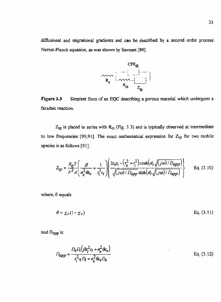
difkionai and migrational gradients and cm be describeci by a second order process
Nernst-Planck equatioq as was shown by Saveant [89].
Figure 3.3 SimpIest fom of an EQC descniing a porous materiai which undergoes a
faradaic reaction.
ZQ is placed in series with k& (Fig. 3.3) and is typically observed at intermediate
to low frequencies [90,9 1). The exact mathematical expression for Ztp for two mobile
species is as foilows [91]:
where, 8 quais:
Eq. (3.1 1)

Dam is the apparent diffusion coefitient [cm2/s], Dc and Di are the diffusion coefficients
of the eleçtron and counter ion [m2is], ci is the concentration of the counter ions within
the film [rno~cm~], c, the initiai concentration of the h e d redox sites (= concentration of
electrons) [rnol/cm3], Zi is the charge of the counter ions, di is the characteristic length of
the transport pathway [ml, A is the cross sectional area of the film [cm2], X, is the
fiadon of redox sites tbat are reduced, tc and ti, respectively, are the transference
numbers of electrons and counter ions, and 9 T, and F have their usud rneaning. The
interaction energy between redox sites, E in I mol-', is described by the parameter P, as
fobws [9 11:
Eq. (3.13)
p and E values larger than zero indicate repdsive interactions between redox sites and,
vice versa, values smaller than zero reflect attractive interactions (see dso Chapters 4 and
Eq. (3.1 0) applies to planar transporf i-e., n is then equivdent to 0.5 and Fick's
first Jaw applies, and when the IR drop across the film is negligible. Also, in this
approach, ions can only cross one interface (fildsolution), while electrons can cross only
the metal/nlm interface; this is refmed to as 'asymmetricd transportf [92]. Further,
acWity effects others than redox site interactions are ignored in Eq. (3.10). Also, charge
transfer at the substrate/film interface is rapid (srna11 W. At sufliciently hi& fiequencies, when o >> 27c JI),pp / d l , the boundary
conditions of transport are semi-infinite. At such fiequencies, Zip in Eq. (3.10) behaves as
a CPE, which is of the weU-known Warburg type [go], since for these conditions, the
hyperbolic functions of Ztp in Eq. (3.10) approaches unity. The EQC in Fig. 3 -3 desenies

then also the system when a CPE, instead of Ztp is used. At Iower fiequencies (If), when o <c ,/&/dl, the boundary conditions are hite and the hyperbolic fùnctions bewme
dominant. Then Ztp is represented by a sinde, ideai capacitor, Cu; connecteci in series to a
transport-related low fi-equency resistance, Rr, which is found to be inversely proportional
to Dapp [91]- (Note that an EQC with a series combination of Rs RK and CE d e s d e s
data collected only at low fiequencies.) The low fiequency capacitor can aiso be referred
to as a supercapacitor or pseudocapacitance in the case of materials such as Ir oxide films,
since the kineticaily reversible oxidati~dreduc~on of Ir(+nI)/Y+IV) invoIves aLI sites
throughout even very thick films.
The transition Eequency (w), which is characteristic of the c h g e of the
boundary conditions fiom semi-inme to finite transport, is reIated to Dam and dl by the
foilowing relationship [93] :
Eq. (3.14)
The transition eequency (atr) can be seen in a Nyquist plot (Fig. 3.5) as the frequency at
which the linear segment (a partly resistive-capacitive TML,) at a 45' phase aq$e (dope of
-dZ"/dZ' = I), representing semi-infinite transport conditions, intersects with the vertical
segment (90' phase angle; slope of -dZ"/dZ' = m), indiathe of f i t e conditions, when the
now fûlly reactùig film behaves as a pure pseudocapacitance. It should be noted t& for
transport behavior other than planar, at intemediate kequencies when insufficient time is
allowed for al1 film sites to react, n differs from 0.5, which lads to a partly resistive-
capacitive T'ML of a non-uniq slope. Similady, the low Eequency, finite transport region
is affected. This is seen by the fm that an ideal capacitive Low fiequency behavior is not
observai in the Nyquist plot, but rather a CPE of mainly capacitive character results.

Changes in the transport type aiso alter the transport equations given In Eqs. (3.9) to
(3.14). Deviations fiom planar transport can also be introduced by porous materiais,
depending on their morphology, and by chernical and physical heterogeneities of the
system [94].
real irnpedance [ohm]
Figure 3.5 Typicai, theoretical Nyquist plot observeci for asymmetrical transport,
showing the semi-infinite and finite transport regîmes. Note that this plot shows onIy the
transport impedance, i.e., other processes such as double layer chqhg, etc., are not
s h o w

EIS data anaiysis
idonnation fiom the experimental EIS data can be extfacted by fitting the
data to an appropriate EQC which is based on a physical mode1 of the system, thus
allowing the evaluation of the circuit elements representing double Iayer charghg,
transporf etc. Mathemarical expressions, which are ofien available in the ïterature,
descnbing these processes must then be found so that the dependence of the magnitude of
the circuit etements can be studied tu jus* both the EQC assignment and to extract
desired iirformation such as ditfùsion coefficients. The dependence of the values of the
circuit elements on the dc bias potential (the film m e ) and the film thickness are genedly
determineci for systems such as Ir oxide.
The experimenta.i ac data should be Kronig-Kramers ~ o r m a b l e [95] to ensure
that the data does not contain systematic errors introduced by chmghg of the system
during the ac rneasurement, for example. Boukamp's software program &en provide an
alternative to the Kronig-Krarners transformation 1961 based on either the Voigt circuit
(Fig. 3 S), which is more appropriate for conducthe systems, or the MaxweU circuit. h
this circuit (Fig. 3 . 9 , any number of resistors and capacitors cm be used. This approach
allows the estimation of the real £tom the imaginary response, or vice versa, even outside
the range of the measured data, thus probing the quality of the experimental data.
The quality of the circuit assignment can also be determined by the relative
residuals, Awi and A h , & which are defined as foilows [95]:
Eq. (3.13)
Eq. (3.14)

2: and Zi" are the reai and imaginary parts of the i' data set measured at ai, whereas
Z'(ui) and Z(ai) are the values of the red and imginary impedances of the EQC studied
at ai. The residuals are either plotted vs. log (a) or as a Nyquia plot. In both cases,
small values (c 0.5%) of the residuals should be spread randomly around the eequency
axis, which indicaies an excellent fÏt. A systematic deviation, however, shows that the fit
is not adequate, Le., circuit elements are missin& the data are not Kronig-Kramers
transformable, etc.
Figure 3.5 Voigt circuit used for alternative Kronig-Kramers transformation when
conduchve systems are midied [96].

Another indîcator of the qualÏty of the data fit is the chi-squared error, XpS, which
is defined as [95]:
Eq. (3.15)
In Eq. (3.15) wi is the weimhing factor- A value of Xp,2 smaller than 2.5 * IO-' shows that
the selected EQC fits the experimental data very well, althou&, the data d e r defines
2 the acceptable value of xp, . Once an EQC has been assigied, it is wise to determine the correlation coefficients
(r) of the circuit etements (x, y, etc.) to ensure that the values of the circuit eiements
calculated fiom the EQC modeiing h c t i o n are vdid, Le. [97]:
where C(,,,) is the covariance:
and V is the individuai variance of the xth or yfi circuit element, i. e. :
Eq. (3.16)
Eq. (3.17)
Eq. (3.18)
N is the nurnber of data points and and are the mean values.

A vaiue of r of +I indicates thai both x and y change by the sarne amornt and in
the same direction, a d u e of -1 shows that x and y change by the same amount, but in
opposite directions, whereas an r of zero results when x and y are compIetely unrelated.
The nature of the inchidual elements determines how they are related, e-g-, r of the CPE,
i-e., o. and its phase dement factor, n, should be close to -1, whereas the r of the solution
resistance and any other interreked circuit elernent ideaiIy wouid be zero.
3.7.3 Ellipsometry
Efipsometry employs monochromatic linearly polarized light which is reflected and
refiacted upon incidence with a sufàce such as an oxide film, as shown in Fig. 3.8. The
amplitude and the phase shifl of the elecmc and the magnetic cornponents of the Li&
wave change upon incidence to an extent defined by the optical properties of the sample,
e.g., the oxide film. The measureà changes in the amplitude (Y) and the phase shifk (A),
which cm be obtained in-situ for different states of the films irnrnersed in solution, are
relatai to the optical film properties by the Fresnel coefficients, rp and r,, as shown in Eq.
("5.19) [33]. ParaIlel p o l e t i o n reIative to the plane of incidence is denoted by the
subscript p, whereas for poiarizâtion perpendicuiar to the plane of incidence, the subscript
s is ernployed.
Eq. (3.19)

The Fresnel coefficients are M e r rejated to the optical properties of the sample, as
folJows:
Eq. (3.21)
In Eqs. (3.20) and (3.21), n, and 4 are the refî-active indices of the ambient and the
sample, the latter being a cornplex quantay, as indicated by the A spbol . a, and ai are
the angles of incidence and refiaction, respeaively, as shown in Fig. 3.6. The cornplex
refractive index, RI, is defineci by:
Eq. (3.22)
In Eq. (3.22), k is the extinction coefficient.
Computer modeling using the changes in Y and A allows the detemination of the
film rehctive index (n), Ïts extinction coefficient (k) and the film thickness (d). n and k
are referred to as effective parameters when they desmie the overall optical properties of
the sample, as nidicated by the subscript 'eE. The porosity of the sample can also often be
extracted from ellipsometric data In this dissertation, the Bmggeman Limit [33,98] will
be applied, which is valid when the volume hcbons of both components of the sample are
comparable, Le., the volume fiachon of component 1 (TI) is more thm 0.05, but less than
20 times the volume fiadon of cumponent 2 ( ~ 2 ) . It is M e r assumed that the mm
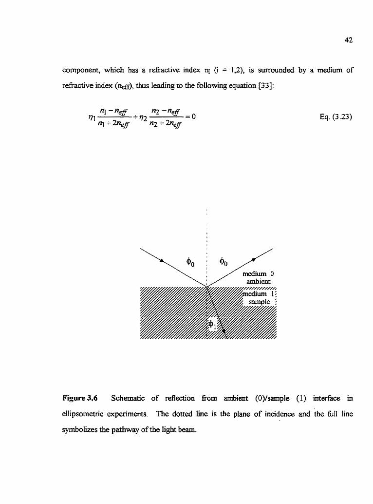
component, which has a rehctive index ni (i = 1,2), is surrounded by a medium of
refiactive index (w), thus Ieading to the fol1owing equation [33]:
Eq. (3 -23)
Figure 3.6 Schematic of reflection fiam arnbient (O)/sample (1) interfâce in
ellipsornetnc experiments. The dotted Luie is the plane of incidence and the hll line
symbolizes the pathway of the light bearn.

C B A P T E R 4
OPTIMIZATlON OF EXPERlMENTAL CONDITIONS TO GROW
IrOXIiBE FILMS
4.1 introduction
The electrochemicai go* as wefl as the kinetics and other characteristics of the
Ir(+III)Ar(+IV) conversion reaction of hydrous Ir oxide films, have been studied by many
researchers in the past [17,48,50,63]. However, a through understanding of the influence
of the growth rnethod on the properties of Ir oxide films has not yet been gained Mso,
the role of the solution on the efectrochernistry of hydrous Ji aide films mrdied in
acidic solutions has caused sorne controversy in ps t years. Questions have been raised as
to whether solution anions are involved in the eiectro~he~cal Ir(-ilI)/Ir(+IV) conversion
reaction [62] andhr whether they are incorporated into the oxïde matrix as bridJing
ligands between n e i g h b o ~ ç Ir sites [70]. h previous investigations, Ir oxide f h~~ were
grown and studied in a range of solutions e-g., in H2S04 HClO4 H3P04, H2C03, etc.,
[50] and characteristic features seen in the CVs of these films were found to depend on the
solution used to study them. As the acidic solutions used În prior work differed in several
of their properties (pH and the activiq of anions), it is unciear whether the observed
difTerences in the CVs were întroduced by the anions andor other hctors. The potential
Limits used during growth, E+g and E-p, and the activities of the anion in the growth
solution, have &O been found to innuence the rate of Ir oxide formation [16,49]. These
studies yielded some insight into the gowth mechanism of these fiIms [49].
In this Chapter, the se ldon of suitable solutions to grow and study hydrous Ir
oxide films is discussed. ï X s is foliowed by a brief discussion of the characteristic
features observed in the CVs of hydrous Ir oxide films which are grown in a range of

acidic solutions. Further, the factors wEch are expected to alter the film properties will be
reviewed
4 2 Sdectioo of the growth solution
4.2.1 Solution composition and concentraüon range
In this work, the influence of the anion of the acidic growth solution on the
properties of Ir oxide films is of interest. This r e q k that the solutions used to grow and
study these films are wmposed of a single acid and that other supporting electrolytes can
generally not be added to the gowth or test solutions. CV studies performed in pnor
work [99] fiirther showed that the thermodynaniic properties of hydrous Ir onde films c m
be influenceci by the solution employed to study them (Le., the 'test solution^. Ln fact, the
pH and the ionic strength of the test solution afTect the properties of these Ir oxide nIms
such as the degree of oxide protonabon/deprotonation, etc. However, film oxidation and
reduction in single acidic solutions of pH c 2 results in mirror-image CVs (oxmidation (Ai)
and reduction (Cl) peaks) [99]. This eases the kinetic and other hidies of these Ir oxides,
as will be discussed in Chapters 7 to 9. Therefm, in this work, Ir oxide films were grown
and studied in strongiy acidic solutions, some of which were dm used in previous work by
others [16,40]. Howwer, it should be noted that hydrous Ir oxide f h s cannot be formed
in hydrohaiogenic acid solutions [100].
4.2.2 Electrochernical stability of the solutions
In this work, electrochemicd side reactions, such as the oxidation and redudon of
the electrolyte, are not desired within the poteniid window used to grow and study Ir
oxide films. Such side reactioos couid distort the characteristic features seen in the CVs
and codd make the determination of the kineîics of the conversion reaction difficult.

Therefore, alI acids used in this wurk are stable to oxidation and reduction within the
electrochemical window required to g u w and study the Ir oxides, Le., between ca. O and
1.45 V vs. the RHE 1491.
4.2.3 Suita ble acids
The following atids were used to grow and study Ir oxide films in this dissertation:
H2S04, HC104 m03, H g 0 4 para-Toluene4Nuonic acid (TsOH) and
1,s-Naphthalenedisulfonic acid (NDSAH). The concentration of these acids was generafly
greater than 0.1 M. The Debye-Huckel Iaw does not apply to solutions of such hi&
cuncentratÏons and therefore, the pH cannot be related to the concentration of the solution
using simple theoretical methods [IO 1,1021. [t should aiso be noted that, in these
solutions, the formation of ion pairs is very kely 110 1,I 021. However, for sirnpticity of
discussion, ail anions wili be referred to as univalent throughout this dissertation.
4.3 Characteristics o f the CVs in dxerent acidic solutions
Fig. 4.1 shows several typical CVs of hydrous Ir oxide f i s grown in different
acid solutions (Section 4.2) by applying potential pulses of 2s duration ('pulse (2s)') at E h
and E,. A11 other growth conditions are ù'sted in Table 4.1. Hydrous Ir oxide films of
large charge densities can be fonned in all solutions studied in this work, as Uidicated by
the large Ai and Cr peaks (Fig. 4.1), representuig the electrochemical Ir(+iiI)/Ir(+IV)
conversion reaction. In fw the oxidation and reduction characteristics of this reaction
seen in the slow sweep CVs are essentialIy si& for all the films studied and appear not
to be strongly dependent on the solution employed (as discussed below).

Potential vs. SSCE M
Figure 4.1 Typical CVs for ir onde f i s grown in a range of acidic solutions bj
(2s) between 1.2 V (except TsOH: 1.12 V) and 4 . 3 V. AU Ir oxides
ca. 26 mc/crn2 equilibrium film charge density and cycied at 1 mV/s, except
puising
are of
for the
ca 5 rnc/cm2 Ir oxïde film grown and cycled (2 rnV/s) in NDSAH. Note that the current
sale for the latter oxide film has been normalized (x 2.6) to compare the CV
characteristics of ibis film to the other îbree Ir oxides. (-) in 0.4 M H2S04;
(........--.-S. ) in 2 M H3P04; (-) in 0.3 M TsOH; (- - -) in 0.1 M M)SAH The Ir
olride films were grown for: 25 min. in 0.4 M H2SO4, 32 min. in 2 M H3PO4,
4 1 min. in 0.3 M TsOH and 10 min. in O. 1 M NDSAH.

TabIe 4.1
Hydrous Ir oxide füm growth conditions in a range of acidic solutions
Grawth and test
soiution
t Thïck Ir oxide films, for which the anodic peak maximum @AI) and peak half-
width (E(1/2)~1) reach constant values, independent of the film charge density,
when v < vq, are considered here
* Al1 potentials are &en vs. the SSCE
0.6 M H C I O ~
0.4 M H2S04
0.4 M HN03
2 M ~ 3 ~ 0 4
0.3 M TsOH
O. 1 M N D S M
E+g**
M
1.2
1.2
1.2
1.2
1.12
1.2
1
E(I/Z)AI
I m V *
Eg**
M
- 0.3
- 0.3
- 0.3
- 0.3
- 0 3
- 0.3
E A ~ **
IV*
0.68
0.68
0.68
0.65
0.68
0.67
140
140
160
150
140
140

In this research, the equilririum film charge density (q) is calailated from the
anodic charge passed up to E A ~ + 0.22 V in a slow sweep CV at Iess than the equiiirium
sweep rate (vq), which ailows for the recovery of the complete film charge [59] for ail of
the Ir oxide films studied. This value is chosen based on prior work [13], which suçgested
that for Ir oxide films g o w n and studied in 0.5 hl H2SO4, the charge passed up to 0.92 V
vs. SSCE (= E A ~ + 0.22 V) is equntalent to one electron per Ir site in the nIm. It is
assumed that this relationship ais0 holds for dl other acidic solutions studied here and that
only Ir(+nI) and Ir(+N) species are stable within this potemial wîndow. Therefore, the
number of active Ir sites within the oxide film can be extracted kom q. Nso, the fraction
of oxidized sites (&) will ofien be caiculated in this dissertation, which is the number of
the oxide sites in the Ir(+[V) state vs. the total number of Ir sites within the oxide film
i.e.. the charge passed to a particdar Ede vs. the totd charge which would p a s in a slow
scan to E A ~ -+ 0.22 V. Frequentiy, the %Ir(+IV) sites wi71 also be caiculated, which is
100 x Xo.
4.3.1 The Al and Ci peak half-widtbs
Fig. 4.1 and Table 4.1 shows that half-widths of the anodic and cathodic main
charge storage peaks, niea~u~ed at half of the peak cwrent, i-e., Q1/2)~1 and E(in)ci, are
much Iarger than the 45 mV predicted for a standard one electron reaction [93]. This may
indicate that the laterai forces between redox sites are repulsive in nature
[103-1051. Fwther, the Ai and Ci peak shapes are seen to be symrnetricai and the
separation between their maxima is mal1 (< 10 mV) for ail films studied in this work when
the sweep rate is suflïciently low.
The values of E(1/2)~1 and E(y2)ci of these Ir oxide films (Table 4.1) were found
to be essentially independent of the solution used in this worlq Le., siniilar values of ca

140 mV were found, except for fÏlms gown and studied m 2 M H904 and 0.4 M HNO3,
which showed peak half widths of ca. 150 mV and 160 mV, respectively, at slow sweep
rates. This indicates that the interaction energies between ne ighbo~g Ir sites [103-1061,
and the potential dependence of the fiaction of oxidized and reduced Ir sites within the
films, are very similar for ail these films. This will be shown to assist the interpreALation of
experimental data throughout this dissertation. Note that these CV characten'stics, which
yield themodynamic information, are independent of the equilibrium film charge densitjes
of the hydrous Ir oxide studied in this research, as long as v < vq.
4.3.2 CV peak potentials
The Ai and Ci peak potentials, which shouid move vs. the SSCE with solution pH
[17], were found to be very similar for the solutions used in this Chapter (Table 4.1). Any
merences found in the values of EA 1 codd indicate a difference in the mV/pH response
of these films (discussed in detail in Chapter 5) and/or could be due to differences in the
solution pH and the liquid junction potentds of the solutions used to p w and study the
Ir oxide films (Section 4.4.1). The very similar values of E A ~ (Table 4.1) iodicate that the
thermodynarnic properties of the Ir oxide films studied in this work are not strongiy
influenceci by the solution This codd suggest that the anions used are probably not
pemanently in the film as bridging ligands between neighboring Ir sites. Nevertheles, it
is noteworthy that the wncentration of anions within these films can be quite large, as
indicated by prior X P S results [34].
I t is seen Pig. 4.1) that the potential of the anodic prepeak, E A ~ , is difFerent for
the various solutions used to gow and study these Ir oxide films, as has been similarly
found in previous investigations [40]. The ongin of this peak is not known with certai~y
[18]. However, the EA, value shifis more cathodically as the sweep rate decreases.

Therefore, at sufficientiy low v, & and AI are tùlly separated, thus dowing the study of
the main charge storage reaction without any interference of &.
4.4 E+g and Eg vaiues used dunag oxide growth
The values of E+g and E-g an4 therefore, dso the rate of the HER and the O E q
are known to innuence the rate of Ir oxide formation [49,63J, thus possibly also
influencing its properties. Both of these readons are affectai by several factors, such as
the pH, the anion, the anion actkity, the oxidation state of the oxide film, etc.
[107,108,34]. In fact, the CVs of Ir oxide films grown and studied in a range of atidic
solutions (Fig. 4.1) show that the rates of the OER HER and the extent of the
H adsorptionldesorption reaction are different in alI of the solutions employed in this
work. Therefore, the iduence of the processes ocnim-ng at Etg and E-g on the
properties of Lr oxide films will be investigated in more detail later in thjs dissertation
(Chapters 8 and 10).
It shodd also be noted that at mflicientiy anodic potentials, some film sites are
oxidized to the Ir(+VI) state, which leads to some dissolution of Ir oxide [12,56]. The
rate of oxide dissolution is influenced by the solution anioq the value of etc.
DifTerent rates of oxide dissolution dunng the formation of these films are also likely to
influence film properties such as the oxide morphology, as different concentration profiles
would develop within the films at different stages of film growth. The rate of oxide
dissolution cannot be made identical in different solutions (during oxide formation), thus
introducinp an additional parameter which Influences the film properties. Some solutions
used in this work were found to strongly enhance the rate of oxide dissolution. Ln fa@ it
was f o n d Uiat in 0.3 M TsOH solutions, hydrous Ir oxide films can neither be p w n nor
studied at anodic potentials 2 1.2 V. Similady, the loss of film charge at potentials more

positive than 2 -0 V was found to be very large when [r oxïdes were grown and studied in
0.1 M NDSAH (Fig- 4.1). The latter observation appears to be related to the oxide
propenîes estabhhed during film growth in this particular solution, as Ir oxide films
grawn in 0.4 M H2S04 can be cycIed up to at Ieast 1.2 V in 0.1 M NDSAH without
losing any film charge.
4.5 Summary and Condusions
Ir oxide films can be grown in a range of different acidic solutions (0.6 M HC104
0.4 M HsS04 0.4 M HN03, 2 M H3P04, 0-3 M TsOH and O. 1 M NDSAH) in which, at
sufficientiy slow v, rnirror-image iike CVs and similar half-widths of the Ir(+iiI)/fr(+IV)
redox peaks are found. Under these equilibriurn conditions, the difference between the
oxidation and reduction peak potentiah are essentiaIIy unaffecteci by the soIution anion
used, even for ir oxide fiIms grown and then studied in soIutions containing different
anions (e-g-, CI04- vs. TsO' and NDSA-). These results suggest that these Ir oxides are
themodynamically very sirnifar in terms of their composition and the forces existïng
between redox sites. However, conditions such as the gowth solution the E+g and
E-g vaiues, etc., do influence the growth rate of the films, and therefore, could alter other
propemes such as their morphology. This may not be recopizab1e fiom the slow sweep
CV characteristics of these oxide films. Aiso, experimental conditions such as the E-g and
E+ vaiues must be selected carefiiily, especially when organic acids are employed (TsOH
and hDSAH), since the oxide iiim is more suscepti'ble to dissolution at anodic potentials
in these soiutions.
CaAPTER5
THE mV/pE DEPENDENCE OF ELECTROCHEMICALLY FORMED Ir OXmE
FILMS
5.1 introduction
There has been some controversy concerning the species involveci during the
eiectrochemicd Ir(+III)iir(+rV) r b o n of eiectrochemicdy grown, hydrous Ir oxide
films [11,62]. Based on their observed super-Nemstian respoose [62], some researchers
have mggesteci that, in acidic solutions, protons and anions, and in basic solutions,
hydroxlde ions and cations, are involved during this reaction in order to maintain
electroneutrality withm the films (Chapter 3).
In this Chapter, the mV/pH response of Ir oxîde films grown in H2S04, HClO4
and HNU3 solutions is reported. The observed mV/pH responses are also compared with
Literature values, as well as examined in terms of factors which can introduce a super-
Ne&an (> -59 mV/pH) response. These factors include the acidhase character of the
Ir(AIII)Ar(+IV) forms of the oxide, changes in the interaction energies of redox sites, etc.
5 3 The mVlpH nsponse
5.2.1 Thermodynamic issues
The electrochemical conversion of transition metal oxide nIms between various
oxidation States is ofken accompanied by the expuision and injeaion of protons or
hydroxide ions fiom and uito them [11,31]. Evidence for the involvement of
protons/hydroxide ions during the electrochemical reaction of eIectrochemicaIIy go-
hydrous Ir uxide films is weii known [3 1,1091 and introduces a dependence of the
equilibriurn potential (eg , E A ~ and Ec~) at slow v on the pH of the solution used to sîudy

them (see below). Systems such as eie~troche~cally grown Ir oxide nIms are offen fowid
to respond in a super-Nemstian marmer, displayinfi a mV/pH dependence larger than -59
at 25 OC [ 1 7 l . This has been explained [17] as beîng due to dEerent acid/base
characteristics of the oxidized and reduced oxide states, which can result in the
expdsiodinjeaion of more than one proton or hydroxide ion per eiectron passed. Charge
compensation is then accomplished by other solution ions. The equiiibriurn potentid @)
of the Ir(+iII)/Y+lV) reaction wouid then be defineci as foilows [17,62], asswning ht
the ciassical form of the Nernst equation applies [17,62]:
In acidic solutions:
and Eq. (5 -2) can be rearranged to:
Eq. (5.1)
Eq. (5.2)
Eq. (5.3)
In Eqs. (5.2) and (5.3), X, is the fiaction of the active Ir sites in the oxide which are in the
oxidized state, x ùidicates the number of protons which are expelled and injected from and
into the oxide film per Ir(+Iii)/ir(+Iv) site (Le., per e') conveited and A- represents
univalent counter anions. AI1 other symbols in Eqs. (5.2) and (5.3) have their usud
meaning.

The c1assica.i fom of the Nernst equation (Eqs. (5.2) and (5.3)) corredy describes
the dependence of % on the solution pH of Ir oxide films when thennodynamic oxide
film properties (other than the acidhase characteristics of the oxidized and the reduced
film forms) are unaltered by the electr~che~cal reaction and the test solution
composition. Kowever, changes in the interaction energy between redox sites (E) and
alterations in the chemical potential of counter ions andor other species within the oxide
film can influence the oxidatiodreduction behavior of these systems, and therefore, can
impact on the value [IO?]. These factors could also Iead to a super-Nernstian rnV/pH
response which would usuaiiy be recognizable &am the CV response [N, 1041. For the
case when E changes with the test solution, the dependence on the solution pH is then
descnbed by a more cornplex fom of the Nernst equation [LW 1. This is shom below for
the example of a one electron reaction involving the expulsion and injection of protons
only [l03]:
Eq. (5.4)
The interactions between redox sites can be repulsive or attractive, resuiting in E vdues
> O or c O, respectively [103,105]. Repulsive forces broaden the potentiai range, resdting
" E ( ~ ~ } A I and E(1n)cl values larger than 45 mV for a one eiectron reaction, and vice
versa, attractive forces result in E(1/2)~1 and E ( I / ~ ) C ~ vdues less than 45 mv, for a one
elemon reaction [103,105]. Aii other symbols have their usuai meaning Both Eqs- (5.3)
and (5.4) apply to systems with energetically equivaient redox sites (Le., uniform E'
values) and the contribution of counter ions and oxide film species-other than protons are
ignored (Le., x = 1). Eq. (5.4) shows that both a decrease in E (dso seen as a demase in
E(~ /~ )AI . and E(1n)cl in the CV, reflectinç Iess repulsive forces) or a decrease in pH

would shift more positively. Therefore, a decrease in E a d o r pH codd umoduce a
mVIpH response of > -59, even for the case when ody one proton per electron is involved
dunng the electrochemical conversion reaction.
In the following Sections, the dependence of and E c ~ of hydrous,
eIectrochemicalIy gown Ir oxide flms on the (acidic) test solution pH will be determineci.
Other CV characteristics such as the haif-width and symmetry of the A1 and CI peaks in
the different test solutions will aiso be discussed to evduate whether any observed super-
N e d a n response may be due to counter anion involvement during the electrochemical
reaction andor to other energetic changes in the aide film properties.
5.2.2 Prior reported mVlpH respooses for Ir oxide films
Burke et al. [17] and Yeung and coworkers [91] observed a linear -85 tu
-88 mV/pH (at 25 OC) dependence for the peak of the main charge storage reaction (EAI
and Ec~) for hydrous Ir oxide flms gown in H2S04- Both goups determined the
rnVipH response in solutions of pH 4 to 12. However, over this large pH range, the
E(112)~l and E(ij2)~i values are &O altered 1911. In fact, changes in E(1/2) of both AL
and Ci of more than 200 mV per pH unit have been reponed for hydrous Ir oxide fiims
[9 1 1. This indicates that the classical fom of the Nernst equation (Eqs. (5.2) and (5.3))
does not account for ail of the fictors infiuencing the dependence of Eq on the solution
pH [ 1033. Pickup and Birss [62] also reported that the rnV/pH response of Ir oxide films,
grown in H2SO4 depends on the test solution pH. They determined the mV/pH response
to be -82 @H ca. 1.5 to 2.5), -70 (pH ca 2.5 to 7) and -87 (pH Ca. 7 to 12.5) in 1 M
KNû3 solutions containing various pH buffen, thus indicating the complex dependence of
on the test solution pH and composition. They also inserted the value of -82 rnV/pH
into the classicai Nema equation (Eq. (5.3)) and sugesteci tfiat

1.4 protons and 0.4 univaierrt anions are injected into the oxide fiIm during Ir(+IV)
reduction, and vice versa, during Ir(t1II) oxidation at Iow pH [62]. They found this
number to agree with the F content of oxidized vs. reduced Ir oxide films [62], studied in
0.1 M HF solutions- This supports their interpretation of the observed rnV/pH response in
acidic solutions, assuming it is unaffecteci by the nature of the anion present.
Other research w u p s have reported that Ir oxide films grown in HC104 respond
in a close to Nemstian fâshion to the solution pH [109,53]. Koa et al. determiaed this
over a broad range of pHs (a 3 to 7) in buffered solutions of varying anion and cation
content. G l a m and Marshall [53] did not report &cient experimental detaiis to adow
an assessment of the validity of their mV/pH resdts; however, it appears that they also
investigated a broad range of pH.
5.23 Determination of the mV/pH response for Ir oxide films in solutions
of low pH
In the present work, the mV/pH response of hydrous Lr oxide films in soIutions of
low pH, which are most commody used to grow and mdy these films, is of interest
(Chapter 4). SoIutions of high concentration, i-e., of low pH, behave non-ideaiiy and the
pH cannot be directiy related to the c o n c e d o n [101]. Therefore, in this work, the
RHE was employed to determine the mV/pH r epose of ca.. 35 mc/cm2 Ir oxide films
grown in 0.4 M H2S04, 0.6 M HCIO4 and 0.4 M HNû3 solutions by puishg (2s) between
1.2 V and -0.3 V. The dependence of both the EAI and E c ~ vdues was obtained in
soIutions made of H2SO4 + Na2S04 assuming that the potentiai of the RHE shifts
-59 mV per pH unit at 25 OC [I IO]. The test solution concentrations ranged between
10" M to 0.75 M HzS04 and O M to 0.74 M NazS04. The E A ~ and Eci values in
different solutions were determined by cycjhg at less than 5 mV/s (< vq), using an SSCE

as the reference electrode. These were plotted vs. the potentials measured between the
EUE and the SSCE in the corresponding solutions. The dope of these plots were
multiplieci by -59 mV/pH, yielding the mV/pH response of the Ir oxide nIms studied in thÎs
work. Note that E m - E s s ~ yields an approximate meanirement of the solution pH
(ignoring the conmiution of Iiquid junction potentials) and a solution pH of O then yieids a
Em-Essc~ vahe of -236 mV [I 1 O]. The solution pH range employed here to determine
the mV/pH response of the Ir oxide nIms is between ca 0.5 and 2.
The Ir oxide filnis were eqdibraîed in the test solution by cychg at 20 mVls for
1 0 full cycles and then at a rate $ vq untiI steady-state E A ~ and E c ~ values were reached,
which occwed rapidly. In fact, E A ~ and E c ~ were found to reach constant vdues rapidly
after film immersion in the test solution over a broad range of pK when the Ir oxide films
were transfmed between 0.5 M H2SO4 and 1 M KOH solutions. This indicates h t
protonatioo and deprotonation of Ir sites within the film occurs rapidly, without the need
to multicycie the h s between the k(+m)llr(+IV) states. The Ir oxide films were cycled
between an anodic potent2 limit (E+) less positive than E A ~ + 0.5 V and a cattiodic
potential lim-t (E-) more positive than EAI - 0.7 V. These E+ and E- values were selected
to avoid dissolution of the oxide (Chapter 4), as well as any irreversible aging effects
frequendy observed with these films at negative E's (Chapter 10).
Before and &er the mV/pH responses were determined ai each test solution, slow
sweep CVs of the films were recorded in the growth solution. The CV characteristics of
the Ir(+UI)/lr(+IV) main charge storage reaction (Ai and Ci) observed in the growth
solution were f m d to be unïnfluenced by the faa that the oxide nIms had been cycied in
different s o l u t i o ~ ~ ~ ~ Identical values of EAI, ECI and equiliibrium film charge densities
were found before and after the mVipH rnewements (see below). This shows that the
film properties defining the mV/pH behavior are reversibly dtered by the test solutions.

The EAI and E c ~ values, as weI1 as the potentiai measured between the SSCE and RHE,
were found to be higly reproducible, with potentiais varying Less than + 0.5 mV.
5.2 -4 mV/pH response for Ir oxide films grown in EitSO4
The CVs for ca 3 m ~ i c m ~ Ir oxide f Ï h s grown in 0.4 M HzS04 and
subsequently cycled at 1 mV/s in 0.4 M HzSO4 and then in two test solutions,
0.05 M H2S04 + 0.75 M Na2S04 and 0.05 M H2S04, are shown in Fig 5.1. (In these
CVs, the current is plotted vs. EdC-E~l for the oxide film in the co~esponding solution to
better compare the data The following E A ~ values were found for these films: 0.68 V in
0.4 M H2S040.59 V in 0.05 M H2S04 f 0-75 M Na2S04 and 0.62 V in 0.05 LM H2SO4.
Ah, newiy formed Ir oxide films were empbyed for each of the two test solutions.)
Similu E ( i n ) ~ i and E(in)cl values of 135 mV + 5 mV were found in the two test
solutions, values ais0 suniiar to the E(~/z}AI and E(I/Z)CI values of 140 mV + 5 mV found
for the Ir oxide film in the gr0wt.h solution ThÏs sugests b a t changes in E are s m d for
the test solutions employed in these experiments. In f q a decrease in E (Ï-e., Less
repulsive interactions between the redox sites) wÏth decreasing pH would act opposingly
to the pH effect, resulting in a mV/pH response of < -59 for a one proton per one electron
reaction (Eq. 5.4). Mso, the symmetry of peaks A i and CI, as well as their peak
separation (EAI-EcI), are uninnuenceci by the test solution This ùidicates that the values V
of - AD at the peak maxima are identical for di test solutions used in this work and that 1-X,
changes in - do not cuntriiute to the experimentdly observed rnV/pH response 1-X,
(Eqs. (5.2) to (5.4)).
An additional s m d cattiodic peak (Co) is observed in the CV for the Ir oxide films
studied in the two test solutions at more negative potentials. This peak is ofien observed

when Ir oxide films are studied at slow sweep rates, especidIy in ~e test solutions, and/or
when cycled between different potential Iimits than ernployed for growth. peak
appears not to intluence the main charge storage reaction, since the equilibriurn film
charge density is not affmed, as shown in Fig- 5.1. Aho, Co is çtill present when these
films are traasfmed back to the growth solution (0.4 M H2SO4), in which identicai EAI,
E(1/2)~1 and q values are found as whm cyckd in 0.4 M irnmediately after growth.
This indicates that some irreversible aiterations of the Mm properties have occurred andlor
may reflect the reduction of oxygen occurring w i t h this potential range at these
electrodes (Chôpter IO). This cathodic reaction, however, appears not to affect the main
charge storage reaction.
ïhe influence of the anion concentration of the test solution on the mV/pH
dependence was carefirJly uivestïgated for ca 35 rnc/cm2 Ir oxide E h grown in HzS04.
Solutions of (approxirnateiy) constant HSO4- concentration, made up with
H2SO4 + Na2S04 or ody H2S04 (HS04' concentration not constant) were used. Fig. 5.2
shows the dependence of E c ~ on E ~ E S S C E in the different test solutions. A very
similar mV/pH response of ca. -68 mV/pH (+/- 1.5 mV/pH) was found in the two cases,
suggestinç that the ~ a - ion does not influence the electrochemicai conversion reaction.
Also, the influence of liquid junction potentids on the mV/pH dependence is [email protected],
since paraile1 EAI and E c ~ measurements directiy vs- the RHE also yielded a -68 mV/pH
response.

Figure 5.1 The idluence of the test solution pH and composition on the CV
characteristics of a c a 35 rnc/cm2 Ir oxide film gown (pulse (2s)) in 0.4 M H2S01
between 1 -2 V and -0.3 V. (-) cycling at 2 mVls in 0.4 M H2SO4 between 1.2 V and
-0.3 V; (- - -) cycling at 1 mV/s in 0.05 M H2S04 between 1-05 V and OV;
(--) cycliog at 1 mV/s in 0.05 M H2SO4 + 0.7 M Na2SO4 between 1.15 V and O V.
All CVs were recorded after 10 cycles at 20 mV/s in the new test solution between the
corresponding limits and then holding the potentid at E- for 10 min
scale for the Ir oxide film cycleci in 0.4 M H2SO4 at 2 mV/s (-)
to better compare the data
Note that the current
has been divided by 2

The experimentally obsewed mV/pH respoose of -68 is smaller than the ca -90
[17,91] observed over a broad range of pH (4 to 12) and that reported by Pickup and
Birss of -82 [62]. The latter group, however, investigated Ir osde nIms g o w and
examined in different (buffered) solutions than done here and involved ody three pH's in
the acidic range, which may have introduced some emor. The value of -68 mV/pH
obt'ned in the present work suggests that more than one proton per Ir site
oxidizedlreduced is expelledhjected ~om/nao the hydrous ir oxide films, since changes in
other energetic fâctors are nedigible or very smaü (Section 5.2.4). Therefore, some
H S O i expdsiodinjection must ais0 occur tu maintain electroneutrality within the Ir oxide
films. The classical form of the Nernst equation (Eq. (5.3)) yieids the relationship between
the number of protons involveci per each electron passed (x) and the mV!pH response
(Le., the shift in the equilibrium peak potential (Mci) with solution pH), as foUows:
Eq. (5.5)
Therefore, the experimental rnV/pH response of -68 suggests that 1.15 r, and therefore,
O. 15 HS04- (x-1 = 0.15 A- (Eq. (5.3)) is involved in the Ir(-III)/Ir(f IV) reaction in Xo is constant and that changes &SU4 solutions of low pH (ca 0.5 to 2). Note that, - LX,
in the activiv of the univdent cornter anion (A3 are ipored.

f - - - - - - - - - - - - - - - - - - - - - - - - - - - - - - - * - A
EO' (x ) ca. 722 mV
I (assumed pH=O) hl
500
Figure 5.2 The mVIpH response of E c ~ for ca 35 rn~/c& Ir oàde fiIms, pulse (2s)
grown in 0.4 M H2S04 between 1.2 V and -0.3 V, as a fiuiction of the test solution
composition. (Ci) H2SO4 + Na2SO4 solutions, (x) in HzS04 solutions. The E*' dues are
estimated vs. the SSCE at conditions where the RHE vs. SSCE is -0.236 V, Le., the
solution pH is assumeci to be O.
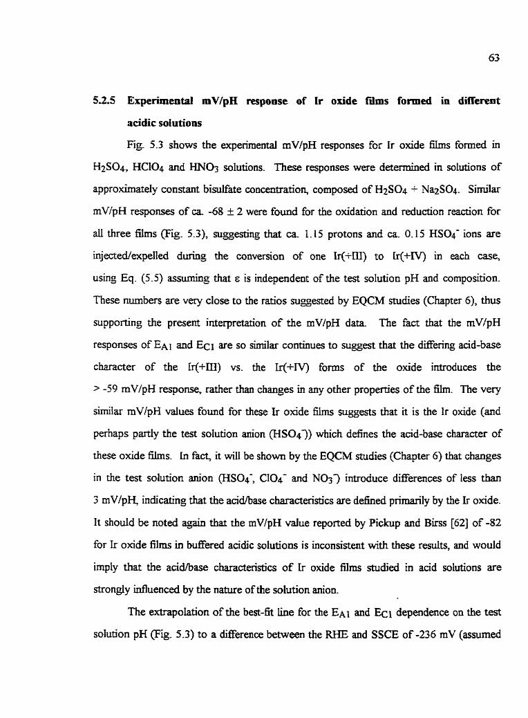
53.5 Experimeotai mVlpH response of Ir oxide fims formeci in different
acidic solutions
Fig. 5.3 shows the experimental mVlpH responses for Ir oxide films fumed in
H2S04, HClO4 and m03 solutions. These responses were deterrnined in solutions of
approximarely constant bisulfate concentration, composed of H2S04 -+ Na2S04. S i d a r
mV/pH responses of ca. -68 f 2 were found for the oxidation and reduction reaction for
ail three films (Fig. 5.3), suggesting that ca 1.1 5 protons and ca. 0.1 5 HSQ- ions are
injectedexpelled during the conversion of one Ir(+IlI) to Ir(+rv) in each case,
usinp Eq. (5 .5 ) assuning that B is independent of the test solution pH and composition.
These numbers are very close to the ratios suggested by EQCM midies (Chapter 6), îhus
supporting the present interpretation of the mV/pH da= The fact that the mV/pH
responses of EA] and ECI are su simila. continues to suggest that the dEering atid-base
character of the W+m) vs. the Lr(+IV) fums of the oxide introduces the
> -59 mV/pH response, rather than changes in any other properties of the film. The very
sirni1a.r mV/pH values found for these Ir oxide Wns suggests that it is the Ir oxide (and
perhaps partiy the test solution anion (HSO43) which defines the acid-base character of
these oxide films. in fa& Ï t will be shown by the EQCM midies (Chapter 6 ) that changes
in the test solution anjon (HS04-, ClO4- and No33 introduce difEerences of less than
3 rnV/pH, indicating that the acidlbase characteristics are defined prîJnarj1y by the Ir onde.
I t should be noted zigin that the mV/pH value repoaed by Pickup and Birss [62] of -82
for Ir oxide films in buffered acidic solutions is inconsistent with these results, and would
irnply that the acid/base characteristics of Ir oxide films studied in acid solutions are
shongly influenced by the nature of the solution anion.
The extrapolation of the best-fit iine for the E A ~ and dependence on the test
solution pH (Fig. 5.3) to a difference between the RHE and SSCE of -236 mV (assumeci

to be at pH = 0) yields an estirnate of EO' (assuning that Eq. (5.3) is valid). Very similar
EO' values of ca 725 to 740 mV vs. SSCE are found for the three films grown in the
different solutions. In fact, these EO values found here are aiso only slightiy lower than
that determinai for hydrous Ir oxide films g o w n in 0.5 M H2S04, Le., ca 770 mV, f h m
the open-circuit potentid (OCP) dependence on a broad range of soIution pH [111]. They
are &O only slightly larger than the theoretical value of c a 680 mV predicted by Pourbak
[56] for the non-hydrous Ir2Q/Ir02 conversion reaction, as foilows:
Eq. (5.6)
5 3 Summary and Conciusions
ïhe mV/pH response of hydrous Ir oxide films, estimateci over a narrow pH range
(ca. 0.5 to 1.5) in acidic bisulfate solutions, has been found to be smailer than the
previously reported values of ca -85 mV/pH 1179 11. However, the latter value was
obtained over a broad range of pH (acidic to alkaline), over which changes in E are large,
and therefore, the cla~sical form of the Nernst equation does not apply. in thjs work, both
E A ~ and ECI were found to shat by -68 mV vs. SSCE per pH unit for Ir oxide films
grown in 0.6 M HC104 0.4 M H2S04 and 0.4 M HNO3 solutions using H2S04 +
'la2S04 test solutions. This indicates that a small number of anions (ca 0.1 5 mole A7 per
mole of Ir sites converted are uivolved in the Ir(+IiI)/Ir(+lV) reaction in sufiric acid
solutions.

Figure 5.3 The mV/pH response for ca 35 mc/cm2 Ir oxide f i s , pulse (2s) grown in
a range of acidic solutions between 1.2 V and -0.3 V, and determined in H2S04 + NqSO4
solutions of constant HSO4- concentration. (m) and (a) E A ~ and Ec~, respectiveiy, for
oxide films gown in 0.4 M H2SO4; (a) and (0) E A ~ and Ecl, respectively, for oxide films
grown in 0.4 M HCIOG (e) and (0) E A ~ and Ec~, respectively, for oxide n Ims grown in
0.4 M W 3 . The lines represent the best hear fit to the experimental daîa:
(-) oxide films g o w n in 0.4 M H2S04; (- - -) oxide films grown in 0.6 M HC104;
(---) oxide fiIms grown in 0.4 M HN@. The EO' values are ghen vs. the SSCE and
obtained at pH M. 0, for the E A ~ data of the Ir oxide f i s grown in 0.4 M H2S04
(ca 740 mV); in 0.6 M HCIQ or 0.4 M HNO3 (ca 735 mV) and for the E c ~ data for ai1
three Ir oxide films (ca 727 mV).
CaAPTER6
LMASS CHANGES ACCOMPANYING THE IELECTROCHEMICAL REACTION
OF EYDROUS Ir OXiDES l?iLMS
6.1 introduction
Electrochemical quartz c r y d microbalance measurements (EQCM) Gan be used
to study the iodsolvent expulsiodijection processes which accompany the
eIectrochemical conversion reactions of materiais such as redox poIymers and hydrous
metai oxide iïirns [112,25]. This technique bas been used to study Ir oxide f3ms grown
electrochemicaily in 0.2 M bS04 and then studied in either 0.2 34 H2S04 or
0.2 M KOH [78]. A reversibIe film mass change of c a 6 @mol Ir sites in the oxide mm
was found to accompany the Ir(+III)/Ir(+rv> reaction in the acidic solution, whereas in
basic medium, a smaüer mass change of opposite sign @e., mass gain) of ca 3 dm01 Ir
was found dunng film oxidatiodreduction. The resuits suggested generally that, during
oxidation to Ir(+IV), protons are expeiied h m the WXI in acidic sdutions and, vice versa,
hydroxide ions are injectai into the film in KOH. However, the magnitude of the mass
changes indicated that not oniy protons and hydroxide ions are invoIved during the
Ir(-IIi)Ar(f IV) conversion reaction, but that counter anions (in acid) and counter cations
(in base), as well as &O, may be injected/expeIled. The invoIvement of counter
anions/cations in the reaction would be consistent with the mode1 proposed by Pickup and
Birss [62], suggested on the basis of the super-Nedan response of electrocheniicaiiy
grown Ir oxide h, as well as on the chernicd andysis of the ionic content of oxïdized
vs. reduced Ir oxide i3ms (see also Chapter 3). It would aiso be highly consistent with the
results in Chapter 5, where pH dependencies of ca -68 mV/pH unit were reported.

In thïs Chapter, the mass changes during the reductiodoxidation of Ir oxide films,
gram and studied in a range of acidic solutions, were detennined and cornpared to the
experirnentd mVlpH response (Chapter 5), as weff as to previously reported EQCM data
The mass change per mole of [r sites reacted over narrow potentiai ranges was also
detemineci as a h c t i o n of the potential (nlni oxidation m e ) and sweep rate.
6.2 General frcquency response during oxidatiodredudion of Ir oride füms in
acidic soIutions
Al1 Ir oxide films were grown on Ir sputter-coated 5 MHz quartz crystais in
0.4 M H2S04 0.6 M HC104 and 0.4 M H N 0 3 by either potentid cycling ( 1 00 mVk) or
potential pdsing (2s) between 1.2 and 6.3 V for 4 to 80 min Equilibrium film charpe
densibes of ca 2 to 7 r n ~ l c r n ~ were established. The Ir oxide &s were rinsed witb ca
200 mL Hz0 before transferring between solutions in their pamally oxidized state, Le., at
~e open-circuit potential of ca 670 mV. The mass change per mole of Ir sites
oxidizedreduced ( A ~ ~ ~ + ~ i r n o I Ir) was esbmated from the mass and charge passed
between 0.2 V and 0.9 V, using v c vq. It is assumed here that only Ir(+lII) and Ir(+IV)
states are stable in t h range of potential, Le., that each electron passed reflects the
electrochemical conversion of one Ir site between the (+III) and (+NI m e s [13, I 131.
The Am~-OXimol Lr value and the o v e d film m a s were generally constant with repeated
cycling and independent of v, unless otherwise stated
A typical CV for a ca. 3.5 mc/cm2 Ir oxide film formed on an ir sputter-coated
quartz crystd in 0.4 M H2SO4 by potentid pulsing (2s) is shown in Fig. 6.la The
voltammetnc characteristics are identical to the response of oxides formai on an ir wire
substrate (Chapter 9, thus justifying the cornparison of üiese oxide films. Fig. 6. l b shows
the typical fkquency change (Af) accompanying the k(+m)/rr(+rV) reaction for the Ir

oxide fiIm gown in and then cycled at 10 mV/s between O and 1.05 V in 0.4 M H2SO4.
This response is consistent with the radon show in Eq. (3.3), since an inaease in the
fiequency (observed during oxidation) indicates that the fïIm mass decreases, consistent
with proton expulsion h m the fiIm, and vice versa, a decrease in the eequency (observed
during reduction) indicates that the film mass increases due to proton injedon (Eq. (3.3)).
It should be noted that other species may also contnbute to these mass changes ( s e Later
in this C hap ter).
The change in frequency was convertecl to mass change using the Sauerbrey
equation (Eq. 3 S), a relationship wïth K = 56.6 Hz per I p@cm2, which is valid for thin
and ngid films [24]. Bkss et al. [78] have s h o w that this condition is m e d for hydrous
Ir oxide films in the range of 1 to 40 r n ~ l c d , as indicated by the hear relationship found
between the equilibrÎurn a m charge density (q) and the frequency change observed during
potential cycling. ui this work, the Ir oxide films studied are actuaiiy very thin (3 to 8
r n ~ d ) , thus justifyrng the use of the Sauerbrey equation [Tg]. The linear relationship
found between the q and Af data is shown in Fig. 6.2 for the ca 3 to 8 mc/cm2 Ir oxide
films grown in 0.4 M H2SO4 by potemial pulsing (2s) between 4 and 16 min., and then
cycled at 1 0 mV/s between 1 .O5 and O V. Extrapolation to zero equilibrium film charge
density results in a close to zero Af(ca O to 1 Hz) intercept, as sidarly found by Birss et
al. [78]. This justifies the application of the Sauerbrey equation to the Ir oxide films
studied in this research.
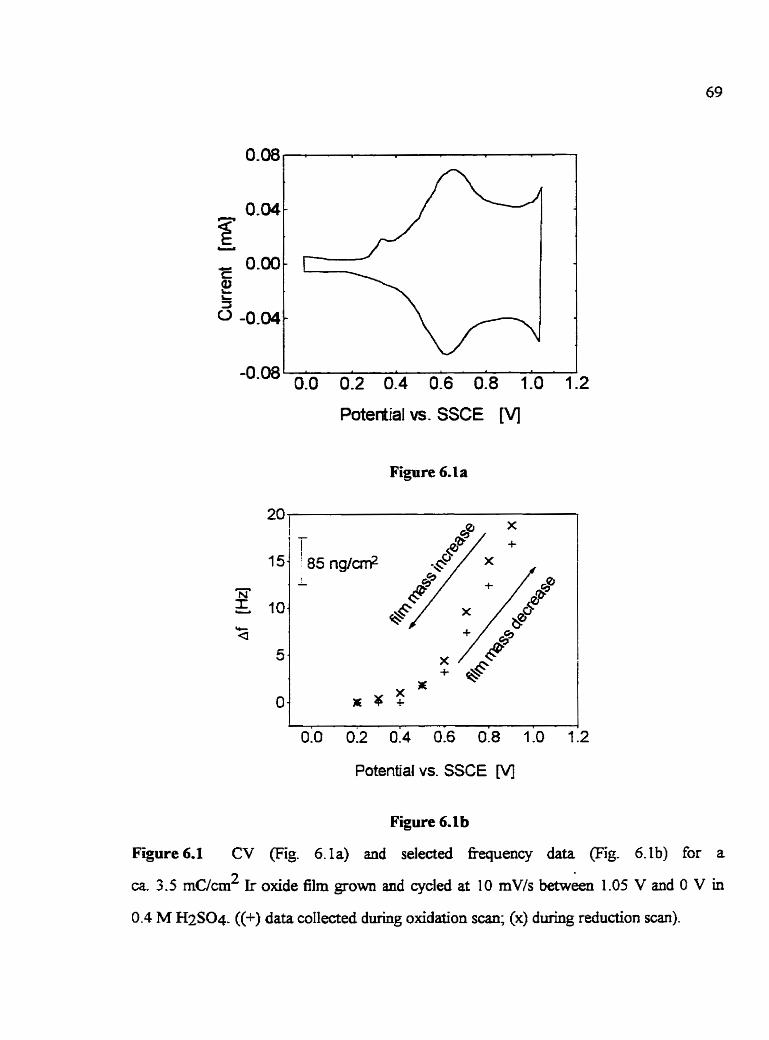
Potedial W. SSCE [Vj
Figure 6. la
20 1
0.0 0.2 0.4 0.6 0% 1.0 1:2
Potential vs. SSCE M
Figure 6.1 b
Figure 6.1 CV (Fig. 6.Ia) and selected fiequency data (Fig 6-lb) for a
ca. 3.5 r n k 2 Ir oxide film grown and cycled at 10 mV/s betwA 1 .O5 V and O V in
0.4 M H2SO4. ((+) data collected during oxidation scan; (x) durhg reduction scan).

Figure 6.2 Frequency change measured during the conversion between the reduced
(0.2 V) and oxidized (0.9 V) States of Ir oxide flms, grown and studied (10 mV/s) in
0.4 M H2SO4 vs. the equilibnum fih charge density. The solid line shows the best Iinear
fit to the expenmental data (x).

6.3 The influence of the growth solution on Am~-Ox/mol Ir
in this Section, the Am~-OX/mol Ir vaiues for the ca 3.5 to 7 rn~/cm' Ir oxide
films, gown by potential pulsing (2s) in either 0.6 M HC104, 0.4 M H2S@ or
0.4 M HN@ and then cycled Cui the gowtfi solution) between 1.05 V and O V, were
obtained. An E- of O V was selected to prevem irreversible alterations of the oxide
properties (discussed in Chapter IO), whereas cycling to E+ vdues less posibve than
1 -05 V prevents the dissolution of oxide.
nie Am~+x/rnoI Ir values for oxides saidied in the different growth solutions
were found to decrease in the followi-ng sequence: 0.6 M HCIO4 > 0.4 M HNO3 >
0.4 M HzS04 (Table 6.1, 2* col-). The Amrd4,/mol Ir values for an individuai oxide
film were hi@y reproducible (Le., -/- 0.08 g/moI Ir), whereas a larger emr of
ca +/- 0.5 ml Ir was fouod for Ir oxide nIms gown in identicai solutions, but on
diEerent crystals. The mass gaiainnoss accompanyïng the eiectrochemical Ir(-m)/Ir(+lV)
reaction are strongly Uifluenced by the growth conditions, thus suggesting that not ody
protons are ivolved during this reacti'on, consistent with previous results [78]. Counter
anions anaor Hz0 may &O be involved in the Ir(+IE)/lr(+IV) reaction [62,78], and
therefore, would influence the Am~i)X/mol Ir value. The fact that several species may
conaibute to the mass change of these oxide films cornpiicates the interpretation of the
EQCM data (see below). Also, rather than H+, is Iikely to be expeiiedhnjected
f rodn to these Ir oxide films, which are very hydrous in nature (Chapter 7). However,
both cases are considered here, showing that the interpretati-on of the EQCM results is not
sigiificantly affected. in the fdlowing Sections, the EQCM data will first be andyzed
assuming that o d y protons and Hz0 contribute to the mass change and then, the case of
counter anion and proton involvement in the electrochemical conversion r a d o n will be
discussed, with and without consideration of Hz0 exchange.

Table 6.1
Mass dmerences between reduced and oxidized forms of Ir onde fiùns grown and
studied in a range of acidic solutions
1 and test
solution
0.6 M
~ ~ 1 0 4
mol A20 per
mol Irx*
[moilm09
A-: O. I I
€If: 1. I l
A-: 0.05
H+: 1.05
A-: 0.07
H+: 1.07
theoreticai #
rn WpH
response
**: Assuming 1 H ~ O + is expelled and one Hz0 is injeaed per Ir site during film
oxidation, and vice versa, during film reduction.
***: Assuming that both protons in the hydronium ion fom and univalent anions (A3
are injectedexpelled during fiim reductiodoxidation and that water is exchanged
for ~~0' ion; this is qu ident to H+ and anion only as the injected/expelled
species.
The theoretical mV/pH response is calnilated based on the data in column 4 Le.,
assuming that no net Hz0 expulsion/injection accornpanks the Ir(+m)lIr(+IV)
reaction.

63.1 Only protons and 8 2 0 involved during the Ir(+m)/Lr(+CV) reaction
(Ont proton per Ir site reacted, 3d coiuntn of Table 6.1)
When only I proton per Ir(+lD)/Ui+nr) site reacted is involved, then the
expuision/injection of other counter ions fÎodinto the Ir oxide f h s is not required to
maintain the conditions of eiectroneutrality. Under these conditions, a mass change of
1 or 19 &mole Ir sites wodd be seen, if H? or were the ody species exchmged,
respectively. However, as the data shown in Table 6.1 (2* colum) are quite different
h m these values, this wodd then suggest the involvement of Hz0 during the
electrochemical reaction. Large amounts of Hz0 have been show to accompany the
oxidatiodreduction reaction of Ni oxides, and in conducting polyrnen, resulting in volume
changes of the oxidized vs. reduced foms of the film [114,115]. These changes of the
Hz0 content of these films are o h recognizable by the metent CV characteristics (ha- width, potemiai, symrnetry) of the film oxidation and reduction peaks [116]. For the case
of hydrous Ir oxide films, a film volume increase of less than 10% has been shown to
accumpany tbe Ir(+III) to Ir(iN) oxidation by n-2-siru eUipsometnc measurements of
similar Ir oxide films as studied in this research [61]. This possibly indicates that changes
in the H20 concentration of hydrous Ir oxide films during the [r(fm)Ar(f IV) reaction are
small, which is consistent with the very similar CV charaaeristics for the anodic and
cathodic peaks (Chapter 4). This also agrees with the smdl number of moles of Hz0
exchanged, as indicated in column 3 of Table 6.1. Note that it is assumed here that the
proton is injected/expeUed in the fom of a hydroniwn ion and therefore, to fit the
experimental data (column 2 of Table 6.1), fkee water must be expelled when the
~~0~ ion is injectai during film reduction, and vice versa during reduction
The observed dependence of A m ~ - O X h i Ir on the gowth solution (Table 6.1,
2"* column) would indicate that different amounts of H20 are expelled and injected

fiodùito these oxide films formeci in different solutions, assuming again that only one
proton per Ir(+III)/Ir(+IV) site is involved in the reaction (Table 6.1, 3rd col-). This
would then suggest that film volume changes, which would accompany film
oxidatiodreduction, wiU depend on the growth solution employed.
6.3.2 Anions are involved during the ïr(+UI)Ar(+W) reaction
(More than one proton is involved per Ir(+m)/Ir(+CV) site converted,
> 59 mVlpH response, 4& column of Table 6.3)
Several studies have yielded evidence for the involvernent of counter anions during
the Ir(+IlI)lIr(3V) reaction in acidic solutions [3 1,1091. This would be consistent with a
super-Nemstian mVipH response, as observeci in the present work (Chapter 5). The
number of protons and univalent anions involved per Ir(+lII)/Ir(-IV) site reacted (Table
6.1. 4& coiumn) were estimated fiom the experimental A m ~ + X h o I Ir values (Table 6.1,
2nd column), in this case assumiflg no net Hz0 exchange, for simplicity. For this
calcdation, the classical fom of the Nernst equatïon and film electroneutrality conditions
were us& assuming no changes in interaction energies between redox sites (see Chapter
5 ) To fit the Am~-Ox/rnd Ir data to the obsewed mVipH response, the
expulsion/injection of K is assumed. However, the data could also be interpreted as
reflecting one Hz0 injected into the film per each expekd during the Ir(+III) to
Ir(-IV) oxidation process, and vice versa, during reduction. Table 6.1 (column 4) shows
that a small, but different, number of anions per Ir site are predicted to be involved in the
Ir oide film reaction in the different gowth solutions. This data was then used to
caldate the expected mV/pH response of the Ir(+m)Ar(+IV) reaction in each solution,
as show in the 5~ column of Table 6.1. (For this calculation the nwnber of protons per
Ir(+m)h(+IV) site reacted was multiplieci by -59 mV/pH, as explamed in Chapter 5).

The predicted mV/pH response for Ir oxide films grown and studied in
0.4 M H2S04 is quite similar (-62) to the experimental vaiue of ca -68 mV/pH found
experimentaily (Chapter 5). This reIatively small difference could suggest that H20 is also
involvecl during the Ir(+IU)/Ir(+iV) reaction. F i g the experimentally observed
Am~+X/mol Ir value of 5.5 grno1 e- to the observed -68 mV/pH response (Chapter 5):
consistent with an anion to Ir site rate of O. 15 HS04-/Ir, this would then suggest that
ca. 0.6 moI of Hz0 per mol of Ir(+IIi)/ir(tIV) sites reacted would also be expelled and
injected fiodinto the Ir oxide films, as foiiows:
A very similar mechanisrn has been suggested by Birss et. al. [78], whq however,
proposed that larger ratios of Hz0 (1 mol H20/mol Ir) and counter ions ( O S moI HS04-
and 1.5 mol Ir) are involved in the reaction. The difference between their results [78]
and those of the present work (even though their value of 6 ghole e agrees very cIoseIy
wiîh the present 5.5, TabIe 6.1) is due to the fact that they fitted their EQCM data to an
estimatecl -90 mV/pH respow. Such a large dependence is only observed over a broad
range of solution pH [17,91] over which the film equilibrium potential is inauenced by
several other &ors [91]. It is ody in this dissertation research that a more precise
measure of the pH dependence of Ir oxide films in low pH H2S04 soIutions,
Le., -68 mV/pH, has been made avdable.
It is of interest also that the Am~+-,X/mol Ir value of 5.5 dm01 Ir found here for
potential pulsing (2s) grown Ir oxide films in 0.4 M H2SO4 is in good agreement witlz the
value obtained for Ir oxide films grown and studied in 0.2 M H2S04 using the potential

cycling method [78]. This indicates that (at least small) changes in soIution pH and
diffaent growth techniques do not sigiificmtiy Séct the film mass gain/loss
accornpanyinç the Ir(tlII)/Ir(+rv) reaction of dectrochemicaliy go- hydrous Ir oxide
film.
OveraIl, these results do suggest that the anion of the growth solution, which is
dso used to study Ir osde films, does influence the mass gaïdoss accompanying the
Ir(+m)/Ir(+IV) reactioq as well as its stoichiometry. The observed mV/pH response,
together with the EQCM r d & , suggest that protons, counter anions and probably Hz0
are aiI involved durÏng this reactÏon.
6.4 The influence of the test solution on the mass change of Ir oùde films during
the Ir(+tU)Ar(+W) reaaion
The influence of the gowth vs. test solution anion on h r e d - O X h ~ l Ir was
investigated for ca 3 mc/cm2 Ir oxide films grown in 0.6 M HC104 by potentiai cycling
(100 rnV/s). mer growth, the Ir oxide films were subsequently cycled at 20 mV/s
between 1-05 V and O V in 0.6 M HCI04 (test solution I), in 0.4 M H2S04 (test solution
II) and in 0.6 LM HClO4 (test solution III). The Ir oxïde films were removed fkom the test
solution, nnsed with Hz0 (ca. 200 mi,) and immersed in the subsequent test sdution
within 5 min. The [r oxide films were cyded in ai1 test solutions until a steady-state value
of A.m&+/mol Ir was reached (see below), Le., for 7 cycles in test solution 1, for 8 cycles
in test solution il and for 10 cycles in the third test solution The CV characteristics of the
main peaks were not altered when the Ir oxide films were potentiai cycled in any of the
three test solutions (Fig. 6.3). Howwer, a net cathodic current was observed in the CV
below ca 0.3 V when the tilms were shidied in différent solutions than used for oxide
growth. This may be reiated to oxygen reduction, typicaiiy observed within this potential

range at these electrodes (Chapter 10). The cathodic m e n t within this potential range
was larger when the Ir oxide film was transfierred to and cycled in H2SO4 and was still
observed when the Ir oxide film was W e r r e d back to and cycled in HC104. These
cathodic aurents were found to reach close to a steady-state value after the fht few scans
in each new test solution. This net cathodic aûrent is fiequently observed when the films
are cycled in different solutions andlor when an Ir oxide film is cycled between difFerent
potential Iimits than used for growth. E A ~ is &O difFerent for the Ir oxide f h s studied in
these solutions (Fig. 6.3). The ongin of the increase in the cathodic cwent and the
prepeak, Ao, is not known with certainty. However, neither of tbese changes influences
the characteristics of the main charge storage peak, as seen by the very similar Ai and Ci
peaks in Fig. 6.3. This indicates that the overall film composition is not influenced by the
reduction reaction occurring below ca 0.3 V.
6.4.1 Overail füm mass (frequency) changes for Ir oxide films oxidizedheduced in
different test solutions
Fig. 6.4 shows the overd frequency change (&-4 v), representhg changes in the
total film mass, for the example of a ca 3 m ~ / d Ir oxide film gown in 0.6 M HC104
during cycling (20 mV/s) between 1.05 V and O V in the three test solutions used in this
Section. The &.4 v values show in Fig. 6.4 were measwed in each anodic scan at 0.4 V
as a fûnction of the number of fidi cycles ofpotentid. It is defined relative to the first scan
in the corresponding test solution
It is seen that in both test solutions il and IU, the o v e d film mass changes wïth
tirne of potential qcling and appears to increase &er a certain number of cycles in both
solutions. A steady-state appears not to be reached, which is unlike the film mass
response in the growth solution.

0 .O 0.4 0.8 1 -2
Potential vs. SSCE M
Figure 6.3 Family of steady-state CVs for a ca 3 m h 2 Ir oxide 61m grown in
0.6 M HCLO4 (100 mV/s) between 1.2 V and -0.3 V and then cycled at 20 mV/s between
1.05 V and O V in different sdutions. (-) test solution 1 (0.6 M HClO4);
(- - -) test solution II (0.6 M H2S04); (-1 test soIution ID (0.6 M HC104).

The change in the overall fiequenw Le., the total film rnass (Fig. 6.4), appears not to
affect the mV/pH response of these oxide nùns, as seen by the fkt that E A ~ and ECI are
not altered when the Ir oxide films are cycled in the three test solutions (Fiç. 6.3). Ako,
this overd film m a s change does not influence the h d + , / m o l Ir value, associated with
the Ir(+m)/Ir(+lV) reaction for £ih studied in test solutions II and III. It should be
emphasized that the overd1 film mass Loss (ca 4 Hz, or ca 12 dmoi Ir in the nrst 8 cycles
in the 2nd test solution, Fig. 6.4) is larger than the expected Amd-ox/mol Ir difference for
test solutions II and III of ca. 6 glmol Ir (Table 6.1). This indicates that the loss of film
mass is not only due to the different mass of the anions behg expeiledhjected frodmto
the Ir oxide nIm during the ir(+m)/Ir(+IV) reaction.
1 x X x X (test solution II) 0.4 M H2 S04
40 -
Cyde #
Figure 6.4 Clveral1 fiequency change ( e . 4 v) for ca 3 mclcd Ir oxide film, grown
in 0.6 M HC104 during cycling at 20 mVk between 1.05 V and O V in different test
solutions, as indicated. The Ir oxide film was grown by cycling (v = 100 mV/s) between
1.2 V and -0.3 V. The Eequency changes were measured at 0.4 V during the anodic sans
and defineci relative to the first scan in the correspondhg test solution.
20 - X 1
X
(test soluüon i ) 0.6 M HCD4
l X I (testsolutionlli)
x X / 0.6MHCLQ
X

The origin and meaninç of the overail Eequency and film mass change* particulariy
in test solution II, is not known with certaÏnty It may refiect the expulsion of some excess
test solution in the case of the test solution II vs. 1. However, it wouid not be clear, then,
why this is followed by an initial overaii tiequency decrease (mas increase) in the E s t few
cycles in the third test solution
The overaii rnass change may be connected to the cathodic m e n t observed below
0.3 V (Fig. 6.3), which is thought to be due to the reduction of oxygen. This reaction
which (on Ir) is a 4 electron process [117,118] involvbg the production of H20, is as
fo~lows:
Eq. (6.2)
The individuai steps involved in this reaction are shown in Chapter 10.
The CVs (Fig 6.3) show that a cathodic charge of ca 0.8 xxC/crn2 is passed in a
single cycle within the potential range of 0.3 V and O V in test solutions 11 and III. This
would be quivalent to the production of ca O. 1 Cl&m2 of H20, using Faraday's law, as
follows:
rn AQM -=- A
Eq. (6.3)
In Eq. (6.3), m is the mass of the product (H20), AQ is the total charge passed, M the
rnolecular mass of the product (1 8 g/mof) and nc is the number of electrons passed per mol
of product (Le., 2). Ail other qmbols have their usuai rneaning. - The production of ca
0.1 j.~g/crn~ of Hz0 and its expulsion h m the film, fiom the reduction of 0 2 present
within the porous structure of the film, would resdt in a fkequency change of ca 6 Hz

(56.6 Hz per 1 pg/cm2). This is very close to the observed overdl fiequency change of
ca 4 Hz during one potenbal cycle in either test solution II or III (Fig. 6.4). Therefore,
the observed overall fiequency changes may reflect the expulsion of Hz0 fiom the Ir oxide
films, which wouid resulr fiom the reduction of 0 2 within the f i l n The ongin of the mass
changes in solution Iti rernain unclear.
6.4.2 The influence of the test solution anion on Amox-&mol Ir
The Af dependence on the potentiai was similar for both 0.6 M HCI04 test
solutions, as shown for the typical example of the fifth cycle in Fig. 6.5. (Note that in
Fig. 6.5, Af for the Ir oxide f Ï l ~ studied in the third test solution is given relative to the Af
value at O V in the fifth anodic scan in the fist test solution). A merence in &equency
for the reduced film (5 ca 0.4 V) is observed, possibly redting f h m the reduction of 0 2
(Section 6.4.1). The sidar Af dependence on the potentid (Fig 6.5) indicates that
potentiai cychg in the H2S04 solution between measurements in HCLQ does not affect
the mass expulsionhjection accompanying the Ir(+In)/Tr(+rv) reaction in the HCQ
solution,
The Am~cOX/mol Ir values in these different test solutions were estimateci between
0.2 V and 0.9 V, as was simjlarly done for the Ir oxide f i s studied in the growth solution
(Section 6 -3). Larger Am~-OX/rnol Ir vaiues of 1 1 -5 dm01 are found in test solutions I
and III (0.6 M HCIO4) than the 5 g h o l d u e seen in test solution II (0.4 M H2SO4). In
fact, the Amrcddx/moL Ir vaiues for Ir oxjde films gown in 0.6 M HC104 and then cycled
in 0.4 M H2SO4 (ca 5 grno1 Ir) are smiilar to the Amrd&nol Ir values found for oxides
grown and cycled in 0.4 M H2SO4 (ca 5.5 dm01 Ir) (Table 6.1). This continues to
suggest that the solution anion does serve as a counter ion during the electrochemicai

b(+m)Ar(+N) reaction, explaining the merence in rnass change in the Merent acidic
soiutioris.
Figure 6.5 Frequency change for a ca. 3 mc/cm2 Ir oxide nIm, p w n in 0.6 M HC104
(1 00 mV/s), durinç cycling at 20 mV/s between 1.05 V and O V in 0.6 M HCD4 (i-e., test
solutions i (0) and il1 (n)). The fiequency changes are given relative to the frequency at
0.4 V measured during the fifb anodic s c a ~ in test solution 1. The fifth oxjdation and
reduction cycles in the corresponding solutions are s h o w ( 0 ) oxidation, (x) reduction.

6.43 Enect of potentïai cyêling vs. pubing dunng oxide growth (test solution 1)
A Amdox/mol Ir value of 1 1 -5 (+/- 0.5) dm! Ir was observed for Ir oxide films
growo by the potentiai cycling method (v = 100 mVk) and then cycled in 0.6 M HClO4-
This mass merence is similar to that for Ir oxide films also gown in 0.6 M HC104, but
formed using the potentiai pdsinç (2s) rnethod (TabIe 6.1). The h r c d + x / m ~ l Ir value of
1 1.5 @mol Ir suggests that 0.12 moles of ClO4- and 1.12 moles of protons are holved
during the Ir(+IQ/Ir(+IV) reaction, assuming that a net expuisiodmjection of Hz0 does
not occur, as follows:
Eq. (6.4)
This would result in a -65 mV/pH response assumjng that Eq. (5.5) applies. The
ciifference of ca 0.5 mol Ir for the pdsing vs. cycling growth methods is very s m d and
lies within the estimated experimental error, consistent with the fact tbat E A ~ (0.68 V) is
the same in the two cases. This demonstrates that the mass ç d o s s during the
Ir(+iII)/Ir(+IV) reaction is more strondy ïdIuenced by the growth and test solutions,
rather than the gr0wt.h techniques chosen here (Le., pulsing (2s) vs. cycling (1 00 mV/s)).
6.5 Detailed anaiysis of mass to mole ratio over n a m w potentid ranges
The dependence of the mass change per Er(+In)/Zr(+Iv) site reacted (dro/Amol Ir)
on the sweep rate (1 O and 50 mVls) over 100 mV intervais was aiso studied in this work.
This is shown in Figs. 6.6a and b for the typicd example of a ca 3.5 r n ~ / c r n ~ Ir oxide film,
gown in 0.4 M H2S04 by potential pulsïng (Zs), and studied at 10 and 50 mVis,
respectively, in the same solution The caldations were carrieci out such that only

posaive M h o l ir values resuited, Le., the mass of the more reduced film was
subtracted Eom that of the more oxidized f o m
Figs. 6.6a and b show that the Wh01 Ir values change with potenual (Le., film
redox state) when cycled at either 10 mV/s or 50 rnV/s, respectively. The overd film
mass change (Amrd-Ox) accompanying the Ir(+In)/Ir(+rv} miction, however, is not
influenceci by the sweep rate ( 1 0 and 50 mV/s), consistent with the fact that the complete
film charge is recovered at these scan rates and overd Am~-ox/mol Ir values of 5.5 gmoi
were f m d (see Table 6.1). The ratio in Figs. 6.6a and b is as low as 2-4 to as high as
10-1 5 &mol Ir at more positive potentials. The non-steady-state nature of the mass
response is particuiarly surpriskg, as the Ir redox reaction is at equilibrium under these
conditions, as sweep rates less than vq are being empbyed. This emphasizes the fact that
the A m ~ - O X / ~ ~ l Ir values iisted in Table 6. I reflect only the total mass change per total
number of Ir sites reacted in a scan up to 0.9 V. Therefore, the present analysis represents
a more detaÏled examimtion of the iodsolvent exchange process.
As the Ir oxide reaction is at equilibnum under the conditions of Fiq. 6.6, based on
the electrochemicd response (i cc v), charge neiarality must be maintaineci throughout the
film at al1 poterrtials. Therefore, the variable mass to moi Ir ratio with potential in Fig. 6.6
shows that the nature of the charge compensation rnechanism andlor the solvent
injectiodexpulsion processes are not at steady-state, making the interpretation of this data
even more cornpiex. The simplest interpretation of this data is that a constant ratio of
protons and anions to moles of Ir sites reacted are injectdexpeiled at all potentials, and
that the variable fàctor with potential is the solvent exchange process. Based on this
assumption, it would appear that during the oxidation scan, water is injectecl into the film
principdly at negative potentiais, such that the measured net mass loss as protons and
anions are expeiled is reduced. At higher potentids, Iess water is injected, so that a Iarger

mass loss, due principally to ion expulsion, is seen In the reverse sweep, partiailady at
50 mV/s (Fig. 6.6b), the reverse processes appear to occur in a sunilar manner as during
oxidation, with water expulsion occurrhg primarily at more negative potentials.
.4t slower sweep rates, however pig. 6.6a), a pater hysteresis between the mass
response in the anodic vs. cathodic scan is seen is sumewhat puzzhg, as the
expectation would be tbat slower sweep rates should be correlated with closer to steady-
-te conditions. Howeveq a closer look at the data obtained during oxidation at 10 mV/s
suggests that closer to steady-state conditions are indeed almost attained, with the m a s to
mole ratio varying only between ca 4.3 and 7.5 g/mole Ir with potential. I t is in the
cathodic scan that a greater hysteresis is seen. P e h p s t h s çuggests that at sufacientiy
slow sweep rates, water is more unifomly gained into the oxide during the anodic scan
with potential. The reverse scan &O shows a greater degree of uniformity (dope of 15
vs. 18 (glmol)N) than at more rapid sweep rates. In short, it is feasïble that if extremely
slow sweep rates were to be useci, the mass changes would become independent of
potenbd.
Another possible interpretation of the data of Fig 6.6 Ïs that the variable ratio with
potential reflects a variable anionic/protonic stoichiometry, such that at low potentials, the
mass Loss during oxidation is primm-ly protonic (iighter species) and becomes
predominantiy anionic (the heavier specïes) at higher potentials, and vice versa, during
reduction. This would lead to a variable mVlpH dependence with the film oladation state.
However, the oxidation and reduction CV characteristics of the very hydrous Ir oxide
films studied here are very sidar, with mirror-image CVs being seen (Chapter 4). This
second interpretation, is therefore considered unlikely, and it appears more reasonable to
assume that the change in the mass response with potential, sweep direction and sweep
rate, reflects non-steady-state water injection/expulsion processes in the film.

skpe ca. 15 (glmol)N /-
1 O;
. - slope ca. 7 (g/mol)N
0:4 0-5 0.6 0-7 0.8 0.9 1.0
&,+S. SSCE M
Figure 6.6a
-2' 1
0.4 0.5 0.6 0.7 0.8 0.9 1.0
hc+vs.SSCE M Figure 6.6b
Fi y r e 6.6 AdAmal Ir calculated over 100 mV intemals for ca. 3 -5 rn~/m~ Ir oxide
films grown and studied in 0.4 M H2S04. Fig. 6.6a shows the d o at 10 mV/s; Fig. 6.6b
at 50 m W . (+) Lr (-Iü) to Ir(ilV) oxidation rwztion; (x) Ir(+IV) to Ir(+m) reduction
reaction. Ede+ reflects the upper huit of the 100 mV intervai being examined. The lines
(-) and (- - -) represent the best Linear fits for £ilm oxidation and reductioq

6.6 Summaty and Condusions
The mass difference between the reduced and oxidized fom of Ir oxide fiIm has
been found to be influenceci primady by the solution anion used to study the oxide, and to
be b o a independent of the growth conditions used (@se vs. cycling method). This
strongiy suggests that both protons and anions are expelleci f?om the oxide film during
oxidation, and injected diiring mm reduction Assumiiy that only protons and anions are
involvecl dunng this reaction, the EQCM results suggest that 0.12 C104-, 0.05 HSO4- and
0.07 NO3- per Ir site serve as counter ions during the Ir(tIE)lIr(+IV) remion. These
dinerences, while cleariy measurable, wodd affect the pH dependence by Iess than
3 mV/pH. The predicted mV/pH dependence (-62) based on the resdts in H2S04 and
assuming that ody protons and anions are exchanged, is very close to the experimentd
mV/pH response (-68) for these Ir oxide films (Chapter 5). The s m d difference possibly
suggests that a net injectîon/expulsion of ca 0.5 mol H z 0 per mol Ir site during film
oxidatiodreduction also occurs.
The mass change per Ir site oxidized, measwed over 100 mV intemals, was found
to depend strongly on the olcidation state of the oxide film, as weil as on the sweep
direction and sweep rates, even though aü nIms were at eiectrochemical equilibrium
(v < vw). This moa likely reflects the expultion/injection of H20, which appears to lag
the Ir(HiI)/Ir(+IV) reaction, especially during film reduction. A larger Hz0 exchange
appears to occur when the film is in the predominantly Ir(+nI) state, such that lower net
mas changes are measured. It is possible that at very slow sweep rates (v vq), the
mass to charge ratio wouid be independent of the potential.
CELAPTER?
EIS CHARACTELUZATION OF HYDROUS Ir OXEDE ]FILMS
7.1 introduction
Hydrated Ir oxide films, primarily in the conducting state, have been studied using
EIS by Glanim and Marshall [53] in H2S04 and HClO4 solutions and by Audrian-Blajeni,
Beebe, Rauh and Rose [Hg] in H2SO4 and saline solutions. Audrian-Blajeni et al.
suggested a particular equivalent circuit (EQC) for Ir oxide films and studied the
dependence of the circuit elements on the experimental variables in order to correlate them
with physical and chemicai cornponents of the Ir oxide film, whde Glarum and Marshall
focused primarily on the interpretation of admittance plots. Both groups viewed these
films as porous in nature and the former group has specdated about the involvement of
HSO4- as a counter ion in the h(III)/(rv) reaction, based on their EIS resuIts.
In the present work, the impedance response of Ir oxide films has been
investigated by forming them in (and transferring oxide films between (Chapter 9)) a range
of acidic solutions. Much of the research has been d e d out in H2S04 and HClO4
solutions. Films grown in H3P04 and paratoluene sulfonic acid, TsOW are also of
interest, since the Ir oxide oxidatiodreduction kinetics were found to be slower in this
medium in preiiminary studies. Values of vq were shown to be relatively low and
therefore, the transport impedance can be rnonitored over a reiatively wide kequency
range. Also, the large size of TsOH would be cunsidered Likely to have a significant effea
on the nIm oxidatiodreduchon kinetics and possibly on the film structure, and hence on
the impedance response, when incorporated into the film and/or involved during the
electrochemical conversion proceu.

In this Chapter, best-fit EQCs for Ir oxide films, primarily in the oxidized or partiy
oxidized f m s and grown under Mnous conditions, were identifiai and compared with
prbr literature for Ir oxides [I 1 91 and related systems [9 t,I20]. The dependence of the
magnitude of the circuit elements on potentiai and film thickness was also established and
campared to information which can be obtahed from both the Nyquist plots and slow
sweep CVs to obtain a physicd mode1 of these films.
7.2 Experimental
Ir oxide films of ca 3 to 50 rnc/cm2, i . e , formed to thicknesses of ca 40
to 700 nm (Chapter 8) by v-ng the t h e of film growth between 4 and 160 min., were
generdy investigated. Films were grown by the potential pulsing method (2s) and were
studied in the same solution as employed for oxide growth (the ' g r o h solution').
Impedance data were collected over a wide range ofdc bias potentiais (Ek) , for both the
dmost IùlIy reduced to the completely oxidized foms of Ir oxide (between 0.25 and
0.9 V). Ed, was varied in either 50, 100 or 200 mV steps between the individual ac
measuremems. Film equilibration was f m d to be estabkhed by holding the potential for
10 s between the 50 and 100 mV steps and 1 minute between the 200 mV steps for glms
gown in H2SO4 and HCQ. Ede was held k e d for 1 min. for ail otber films. AU other
conditions employed are descriied in the appropriate section of the text. The ac
perturbation did not innuence the properties of the films, as seen by the fact that the ac
responses were found to be independent of the direction of frequency change. This was
also reflected in the sirnilar appearance of the CVs recorded at sweep rates lower than vq
before and &er a set of ac experirnents were carried out. Also, the growth solution was
frequently changed (ca every 10 hours) to avoid any concentration changes which might

occur over long periods of expehentation. The conditions of film growth listed in Table
7.1 were employed, as discussed in Chapter 4.
Table 7.1
Ir oxide f i m growth conditions
growth solution -- -
0.7 M HCi04
0.4 M HzS04
2 M
0-3 M TsOH
The vq values are estimated for equüibnwn film charge densities of
c a 26 m ~ / c r n ~ ; ail Ir oxjde films are pulse (2s) grown.
A similar dependence of the percentage, and therefore, also the fraction of [r(+lV)
sites (Xo), on EdcE~ 1 was found for dl films, as show in Fiç. 7.1 . (The calculation of
the percemage and fiaction of ir(+IV) sites is descnied in Chapter 4.) Therefore, the ac
data of dl films is compared at the same E&-EAI values in this work lt should be noted
that the oxide gowth conditions in the HClO4 solution involved a difFerent E-g value and
solution concentration (0.7 M instead of 0.6 M) than generdly used in this work, since
these Ir oxide films were then f m d not to be prone to irreversible and undesired

alterations of the mm propem'es, a pbenomena which is often observed for Ir oxide films
studied in HClO4 solutions (Chapter 10). E(1/2)~1 and E(in)cr d u e s of 140 rnV were
found for the Ir oxïde films g o w n in 0.7 M HC104 similar to the d u e s for the other
films studied in this research (Chapter 4). The vq values for the four Ir oxide films were
found to be differenf as shown in Table 7.1, for the example of ca. 26 rnc/cm2 h. In
fact, vq decreases in the order of HClO4 > HzSO4 > > H3P04 a TsOH. The differences
in these vq values may be due to anion rnobility differences within the films andfor other
effects of the gowth conditions on the film properties. These issues d l be discussed
M e r throughout this dissertation.
Figure 7.1 Dependence of % Ir(+IV) sites in ca. 26 rnc/cm2 Ir oxide films gown in a
range of acidic solutions, as listed in Table 7.1. (0) 0.7 M HC1O4, (0) 0.4 M H2S04
(A) 2 M H3P04, (O) 0.3 M TsOH.

7.3 EIS response and the seleetion of the bat-fit equivalent circuit (EQC)
Figs. 7.2 a and b show mical Nyquia plots of two Ir oxide f i s gown in HzS04
and H3P04 solutions, respectively. They are both ca 80% in the Ir(+lV) state and have
an equilibrium charge density of ca 10 rnc/cm2. This type of EIS response shows a partly
resistive-capacitive transmission Iine (TbK) at intemediate frequencies and mainly
capacitive behavior at low fkequencies. This is very similar to results reported for redox
polymer films [93,120] and found for al1 conductive Ir oxide films studied in this work
Therefore, theories which have been applied to these well studied polyrner systems, which
were also discussed in Chapter 3: will be directed to the Ir oxide films studied in this
work. Figs. 7.2a and b show t h a ~ although the ac response of these two films are
qualitatively similar, siJnificant quantitative differences exist. For example, the values of
the transition tiequencies (Chapter 3) are ca 50 s-' and 6 s-', respectjvely, indicating large
kinetic differences. In fact, tbis suggests a faster Ir(+III)IU-(+IV) reaction rate for the Ir
oxides grown and studied in H2SO4 vs- H3PO4, consistent with the vq data (Table 7.1).
The Ir oxide f2m grown in H3P04 is clearly more resistive than the film g o m in H2S04
as seen by the mer Rif of ca. 24 vs. 6.5 ohm in Fig. 7.2. This is also consistent with the
kinetic differences observeci fiom the transition fkequencies, as RI^ is inversely
proportional to DW (Chapter 3). The Nyquia plots show hi& frequency intercepts
(when -ZW is zero) of ca 2.3 and 6 ohm for the Ir oxide nkns studied in 0.4 M H2SO4 and
2 M H3POa respectively, yielding the values of the solution resistance, Rs, discussed
m e r in Sedon 7.4.2,
For convenience, the fiequency range investigated in this work is divided into three
regions, Le., the hi& fiequency (hf), intemediate (in@ and low frequency (If) ranges. As
shown in Fig. 7 2 , the If region descnies the mainly capacitive ac data, whereas the
mixed resistive-capacitive TML represents the int frequencies. The h f range yields the

solution resistance, Le., it is equivalent to the hf intercept with the real impedance axk.
The frequencies definhg the intersections of these three regions were found to depend on
the gowth solution employed and on & (Section 7 - 4 3 .
O 2 4 6 8 I O 12
reai impedaice [ohm]
Figure 7.2a Typicai Nyquist plot for ca 10 rnc/cm2 Iridium oxide film (a. 80%
Ir(+IV)), p w n by puising (2s) between 1.2 V and -0.3 V. The ac data were collected at
EdcE~l = 130 mV over the fiequency range of 100 lcHz to 1 Hz. The Ir oxide film was
p w n and examineci in 0.4 M H2S04. All other growth conditions are iisted in Table 7.1.

O 30 60
reai impedance [ohm]
Figure 7.2b Typicai 'lyquist plots for ca 10 mc/cm2 Iridium oxide nIm (ca 80%
Ir(+IV)), p w n by pulsing (2s) between 1.2 V and -0.3 V. The ac data were collected at
= 130 mV over the frequency range of 100 1<Hz to 0.1 Hz. The Ir oxide film was
gmwn and examined in 2 M H3P04. AU other growth conditions are iisted in Table 7.1.
Best-fit EQCs have been assi@ to al1 ir oxÏdes films studied here (Fig 7.3). The
EQC in Fig. 7.3a fits the hf and intf data and is refened to as the semi-infinite circuit,
whereas the circuit shown in Fig. 7.3b fits the If data range, thus being referred to as the
finite EQC. For the aimost &Ily reduced film state, a capacitive if range is not seen within
the frequency range investigated in this work and, in this case, Fig. 7.3a fits the complete
fiequency range and is again rderred to as a semi-infinite circuit- In the present work, it

has been found that the optimum arrangement and number of Qrcuit elements for these
two f o m of the film do not depend on the growth solution employed AU other circuits
have been rejected on the bais of a mis-match between the c d d a t e d and experimental
spectra, ie., large chi-squared and Least square fit errors of the elemerrts (Chapter 3). It
will be shown that CP& and Cif are both related to the transport of electrons and counter
ions within the Ir oxide film. under semi-infinite and finite conditions, respectively. (as
discussed in Chapter 3). Therefore, these two elements can be combined into a single
transport element, Zlp and a sinçle circuit (Fip. 7 . 3 ~ ) then reçults Eom the combination of
the two EQCs in Figs. 7.3a and b, thus desa-ibing the complete ffequency range.
It should also be noted that attempts were made t o £3 the experimental data over
the complete fkquency range to the EQC in Fig. 7 . 3 ~ using a circuit element for Zlp
provided by Boukamp's software. However, the type of transport for the films studied in
this work is not strictty planar, Le., the Ztp element provided by Boukamp's pros-
which desmies plaw, asymmetnd transport includùlg both the semi-idhite and finite
regïmes, does not fit d of the experimental data obtained for these Ir oxide films.
Attempts to fit the complete fiequency range of the experimental data to this single EQC
failed for the Ir oxide nIms grown in &P04, as weIl as for less conductive Ir oxide films
in dl solutions (< ca 35% Ir(+N) sites). Therefore, the If data had to be separated f h m
the hf and intf data, Le., the assigiment of two separate EQCs for these fkequency
domains (Figs. 7.3a and 6) was required in order to analyze the data in this work.
The circuit in Fig. 7.3~ is similar to that proposed by Aurian-Blajeni et ai. [119],
who, however, ultunately assigied some of the elements to Werent physical processes
than done here. They also viewed the elements considered here as CPEs as ideai
capacitors, and vice versa, elements considered to be ideal capacitors in this work were
CPEs in theirs. Attempts to fit the experimental data obtained in this work to their circuit

were not successful. Another important and peculiar merence is seen by the fact that, in
the present work at low frequencies (Kg. 7.2), the supercapadance due to the
Ir(+EI)/(+IV) redox reaction (Section 7.4.4) dominates the irnpedance response, while
Aurian-Blajeni et al. do not observe mainly capacitive behavior at low Eequencies. It is
possible that they did not access sufiicientiy Low fiequencies to reach the finite boundary
conditions for transport required to observe this pseudocapacitance [119]. Althou& their
film charge densities and fkquency ranges are si& to the experirnentai conditions
selected in this work, Ï t appears that the filni properties investigated in these two studies
do differ. GGlanun and Marshall [9 11, however, appeared to have observed fi properties
similar to those in this work, since they observed the mainly If capacitance response in the
same fiequency range as seen here.
The excellent agreement between the experimentai data and the theoretical ac
response, based on the EQCs of Figs. 7.3a and b, is shown in Figs. 7.4 to 7.6 for çome
wical data obtained for both a close to fully oxidized (ca 80% Ir(+IV)) and an almoa
f U y reduced (ca. 20% Ir(+IV)) 26 mc/cm2 Ir oxide film formed in H3P04. Fig. 7.4a
shows the experimental(+) and the theoreticai (x) data @ased on the EQC in Fig. 7.3a) in
the Nyquist representation, whereas the residuial errors for this fit are shown in Fig 7.4b,
for the predominantly oxidized film
The data show here in Fig. 7.4 are for the hf and intf range, Le., 100 lcHz to 2 H z ,
and the lf data are not hcluded in this fitting procedure* Figs. 7.5a and b show only the If
data, Le., < ca 1 Hz, fitted to the circuit of Fig. 7.3b for the same oxide film. Figs. 7.6a
and b show the same representations for the semi-infinite conditions of the almost fully
reduced film (between IO0 kHz and 0.1 Hz) as shown in Fig. 7.4 for the predominantly
oxiciized film. The chi-squared fit errors for the partiy oxidized film (Fig. 7.4), fitîed to
the EQC in Fig. 7.3% have satisfactorily smal values, i e . , 3 * 1 o - ~ and 1 * lo4, respectively .

Figure 7.31
Figure 7 3 b
Figure 7 3 c
Figure 7.3 EquivaIent circuits (EQC) assigneci to Ir oxide films gown and studied in
acidic solutions and with more than 10% Ir(+N) sites within the films. The EQC in
Fig. 7.3a descnbes the case of semi-infinite conditions (Le., the hf and intf data), whereas
the EQC in Fig 7.3b d e s d e s the ac data for only the If range. The ac data of the
complete @$ intf and if) tiequency mge, Le., for both semi-in6nite and finite transport
conditions, are describeci by the EQC in Fig. 7 . 3 ~ .

reai impedance * 1 [ohm]
Figure 7 . 4 ~ Overlay of experimental (*) and theoretical (x) ac response for
ca. 26 r n ~ / c m ~ Ir oxide film grown (pulse (2s)) and examineci in 2 M HP04 using the
Nyquist plot representation. The ac data were collected at Q c - E ~ l of 150 mV, Le., the
film is in the primarily oxidized form(ca 80% Ir(+IV) sites), and the tiequency range
between 100 kHz and 2 Hz is show here. The Ir oxide film was grown between 1.2 V
and -0.3 V. Ail other growth conditions are listed in Table 7.1. The experimental data
was fitted to the semi-infinite EQC shown in Fig 7.3a.

Figure 7.4b Residual mors vs. the fkquency found for ca. 26 rn~krn* Ir oxide mm
gown (pulse (2s)) and examïned in 2 M H3PO4. The ac data were coffected at E d c E ~ l
of 150 mV, Le., the film is in the prima* oxidized form (ca. 80% Ir(+IV) sites), and the
frequency range between 100 kHz and 2 Hz is shown here. The Ir oxide film was grown
between 1.2 V and -0.3 V. Al1 other growth conditions are Listed in Table 7.1. The
expenmentd data was fitted to the semimiinfinite EQC shown in Fig. 7 . 3 ~ (x) real residud
error, (0) imaginasy residuai error.

reaf impedance * lo2 [ohm]
Figure 7.5a Overlay of experirnentai (+) and theoretical (x) ac response for
ca. 26 mc/cm2 ir oxide film gown (pulse (2s)) and examineci in 2 M Hg04 Gng the
Nyquist plot representation The ac data were coflected at of 150 mV, i-e., the
film is in the prirnarily oidized fom (ca. 80% Ir(;N} sites), and the fkpency range
between 1 Hz and 0.1 Hz is show here. The Ir oxide film was grown between 1.2 V and
-0.3 V. Al1 other growth conditions are listed ni Table 7.1. nie expenmental data was
fitted to the £hite EQC shown in Fig. 7.3b.

Figure ?Sb Residual errors vs. the fiequency found for ca 26 m c h 2 Ir oxide film
grown (pulse (2s)) and examined in 2 M H3P04 The ac data were collected at Edc-E~l
of 1 50 mV, Le., the film is in the primarily oxidized fom (ca 80% Ir(+IV) sites), and the
fiequency range between 1 Hz and 0.1 Hz is show here. The Ir ogde film was grown
between 1.2 V and -0.3 V. Al1 other growth conditions are Listed in TabIe 7.1. The
experimentd data was fïtted to the hite EQC shown in Fig. 7.3 b. (x) reai residud error,
(0) irnaginary residuai error.

Figure 7.6a Overlay of expenrnental (*) and theoretical (x) ac response for
ca. 26 r n ~ / c m ~ Ir oxide film gown @dse (2s)) and exarnined in 2 M H3P04 using the
Nyquist plot representation. The ac data were collecteci at EdcE~l of -180 mV, Le., the
film is in the primarily reduced f om (ca. 10% Ir(+rv) sites), and the kequency range
between 100 kHz and 0.1 Hz is shown here. The Ir oxide film was gown between 1.2 V
and -0.3 V. -4U other growth conditions are Iisted in Table 7.1. The expenrnentai data
was fitted ta the semi-infinite EQC shown in Fig. 7 . k

Figure 7.6b Residual errors vs. the fiequency found for a ca 26 rnUcm2 Ir oxide film
grown (pulse (2s)) and examined in 2 M H3P04. The ac data were cuilected at &&AI
of - 1 80 mV, Le., die film is in the primarily reduced f a n (ca 10% Ir(+IV) sites), and the
fkquency range between 100 kHz and 0.1 Hz is show here. The Ir oxide film was grown
between 1.2 and -0.3 V. AU other growth conditions are listed in Table 7.1. The
expenmentai data was fitted to the semi-infinite EQC shown in Fig. 7 . 3 ~ (x) r d residual
erra5 (a) imaginary residual error.

However, a chi-squared e m r of Iess than 1 * la4 for the Mting of the If data (Fig. 7.5) can
be reached only through the collection of SuffiCient If data, Le., fiequency measurements
over at least one decade would be required. Also, the 1- squares M errors for each
circuit element are mal1 and Iie between 1 and 6%. However, the residuals, Arcj and
Ah, i , are not always spread randomly when plotted vs. log (f) (Figs. 7.4b, '?Sb and 7.6b).
For the less conductive film, a systematic deviation is f m d , as show in Fig. ?Ab, for the
aimost fùlly reduced (ca 20% Ir(+IV) sites) film guwn in H3P04- The Kronig-Kramers
t r ~ o r m yielded satisfàctonly low erron for the more conductive films (more than 80%
lr(+nI) sites), i-e., typicdly l*W5, whereas enors of 5*10J for the Less conductive fiim
were found. The Iarger errors for the Latter cannot be ascribed to alteration of the fïim
propedes with time, since the ac responses of these films were uninfluenceci by tirne. It is
possible that non-idealities, such as a large IR drop across the non-conductive film, might
introduce the need for more than one constant phase element possibly explaining the large
errurs of the residuals. Therefore, the quantitative analysis of the non-conductive form of
Ir oxide films, Le., when more than ca 80% of the sites are in the Ir(-III) state, was not
attempted in this work.
7.4 Anaiysis of the ac data
Tables 7.2 and 7.3 show typical correlation factors for the C N L S (cornplex
nonlinear least squares) fits for both EQCs of Figs. 7.3a and 7.3b7 using the example of a
ca 40 rnc/crn2 Ir oxide films grown in H3P04 and in the ca 70% (Table 7.2) or ca 20%
(Table 7.3) Ir(+N) state. Al1 of the circuit elements are fond to be strongly interrelateci,
Le., a slight change in the magnitude of one element affects the magnitudes of the others.
(The closer the r value between two elements is to 1, the larger is the interdependence of
the two elements (Chapter 3)). In fact, the interdependence of some of these elernents is

physically unreasonable, as will be show in Section 7.4.3. For these reasons, quantitative
informatiori was ofken extracted fhm the raw ac data in the NyqWst representation, since
the EQC approach was, in these cases, misleading. Nevertheless, the ac response of these
films will be disnissed using the EQCs in Figs. 7.3a and 7.3b, since the arrangement of the
circuit elements do have a valid phyacal meaning.
7.4-1 Comments ta theoreticai models used in this research
It will be shown Cui this Chapter) that each of the EQCs in Figs. 7.3a to 7 . 3 ~
contain elements (Le., Ztp CPG and CK) which represent the transport of electrons and
counter ions within the Ir oxide films. Three mobile species, electrons, protons and
anions, are Iikely to be involved during the Ir(+III)/Ir(+N) reaction of electrochemicaily
gmwn Ir oxide £i.ims in acidic solutions [62]. However, the conmbution of the wunter
anions to Ztp of these films may be negiigible, since ody a smaii number of per Ir
site converteci is involved (Chapters 5 and 6 ) and the influence of the counter anions on
the equlibrium potentiai of these oxides is minor (Chapter 5). Therefore, transport within
these Ir oxide films is assumed to be sufficiently desmied by Eqs. (3.10) to (3.14), which
consider die influence of ody two mobile species on Ztp- However, this assumption
wodd not be correct if anion transport were rate LimitUig in the film oxidatiodreduction
reaction.

Table 7.2
Correlation factors* (r) of CNLS fits to the semi-infmite EQC of Fig. 7.3~
(For a ca 40 mC/crn2 Ir &de film pulse (2s) gown in &PO4 between 1.2 V and -0.3 V
vs. SSCE.)
(a) ca. 70% ir (+IV) sites
(b) ta. 20% Ir(+IV) sites

Table 7.3
Correlation factors (r)* of CNLS Fm to tbe rinie EQC of Fig. 7.3b
(For a ca 40 mc/cm2 Ir oxide film pulse (2s) grown in between 1.2 V and -0.3 V
vs. SSCE.)
(a) ca. 70% ir(+W) sites
= 1 40 mV, and for the fiequency range of 1 Hz to 0.1 Hz)
(b) ca. 20% ir(+W) sites
(EdcE~l = - 1 60 mV, and for the frequency range of 0.1 Hz to 0.0 1 Hz)
The correlation factors were estirnated using a software program (Equivalent
Circuit, version 3 -97) written by B. A Boukamp of the University of Twente.

7.4.2 The higb fmquency cutoff mgion
R, - This element, obtaù>ed at the hf limit (Fig. 7.2a), represents the resistance of
the bulk electrolyte solution between the Ir oxide surface and the Pt wire reference
electmde. It is independent of Ir oxide film thickness (ca 40 to 700 nm) and of the
applied dc potentid, as it shouid be. Its mafinitude, calculated by the EQC approach
aJrees with the hfcutoff intercept on the real impedance axîs of the experimental Nyquist
plot and is generally between 1 and 10 ohms, depending on the concentration and nature
of the electrolyte solution and the location ofthe workmg and reference electrodes.
7.4.3 interfacial processes
CPEa and & - These two elements are believed to represent the double Iayer
charginç of the Ir substraxe and the resistance to charge transfer at the substrate/flm
interface, respectively, consistent with their location in the EQC (Figs. 7.3a and c) and as
found for related systems [27,29,91]. The EQC approach to the estimation of the
magnitude and dependence of these two elements on the experimental variables was found
to fa3 completely, since this element does not behave ideally (distorted semi-circle) and its
value is very small for the more conductive nIms (see below). Quantitative Somation
about & and CPEdl for these Ir oxide films codd therefore, not be extracted f?om the
raw ac data, but rather ody semiquantitative estimates of their magnitude and their
dependence on the potentiai could be obtained.
Fig. 7.7 shows a typical M y of Nyqujst plots for a ca 26 m c / m 2 Ir oxide film
gown in HCIO4 and examined at different Ede. The ac data in the Nyquist plot
representation appear to approach a semi-circle at hf for the Iess conductive films
@dc < EAI (O), (O)). The width and the height of the hf semi-circle both decrease as the
nIm is made more conductive and, when > E A ~ (O), the semi-circle is hardly

noticeable in the Nyquist plots for aii the oxide films studied in this research. The width of
the apparent semi-circie yields the value of Rd, as described in Chapter 3. However, this
hf f-e is not dearly defined for these Ir oxide flms, aiiowing only its semi-quantitative
estimation. Also, especially for more conductive tSIms, the semi-infinite transport element
(CF&) is cleaily recognizable in the Nyquist plots, as it should be, when Ra is srna11 and
not rate Iiïniting to the film oxidation/reduction r-on [92]. CPEG represents the
transport of electrons and counter ions within the oxide &II (Section 7-43}, and contains
the heteroçenous eIectron rate constant (Le., aIso the charge t r d e r resistance) to the
oxidation/reduction of the Ir sites within the film [89,12I, 1221. Saveant bas shown that
the transport of eiectrons withùi the film is similar to diffüsion in solution (i-e., Warburg
eIement [84]). Therefore, the transport of eiectrons is seen as a linear segment in the
Yyquist plot and is also often referred to as a i o n of elemons [89].
ïhese resuits suggest that rnay decrease exponentially with increasing Ede, as
would be the case when the reaction foilows Butler-Volmer behavior [123]. This is
similariy assumed for related polymer systems [93,91,121]). In fact, & estimated
graphicdly fiom the widths of the apparent hf semi-circles Fig. 7.7), is found to be very
srnaIl for ail of these films, when the percentage of sites in the oxidized state is larger tfian
ca. 20% (Table 7.4). The value of estirnateci at Ede = EAI E Eq, Le., when
ca. 50% Ir(+IV) sites exist [123], shouid ailow the estimation of the heterogeneous rate
constant, kO, which describes the charge transfer rate, ignoring laterai interactions, as
foUows 1 1231 :
Eq. (7.1)

where i, is the exchange current density and ail other symbots have their usual meaning.
Table 7.4 shows that & is very small, Le., c 0. I ohrq as Ldc approaches EAI.
(Also, for E d c E ~ ~ > O, Rct vaiues smalIer than 0.1 ohm were found for al1 Ir oxide films
studied in this work.) This yields (Eq. 7.1) very large ko ( > 1.3*W3 c d s ) and
i,, ( > 8.1 * 1 values, which indicates very rapid charge transfer at the
substrate/film interface for the more conductive form of the film (Le., > 20% Ir(+IV)) in
al1 solutions. (Note that a i, value of 10-' A/m2 reffects rapid charge transfer, wwhereas
vaiues between 104 and IO-' A/crn2 are referred to as quasi-reversibie, Le., indicating
slower charge ansf fer [123].) Rapid transport justifies the mathematical trement,
discussed in Chapter 3 for these films.
5 10 15
real im pedance [ohm]
Figure 7.7 Typical h i l y of Nyquist plots for different oxidation states of a
Ca. 26 mc/cm2 Ir oxide film gown and studied in 0.7 M HC104. The ac data are s h o w
fiom 100 kHz to Merent lower fkequencies, as indicated in the plot. The ac rcsponse at
different EdcE~l were investigated : (0) -190 mV, (0) - 140 rnV, (0) 10 mV.

I I I
Table 7.4
Approximate & values estimated from experîmental Nyquist plots for different
oxidatioo states of ca. 26 r n ~ / a n ~ Ir oxide f h s grown (pulse (2s)) and studied in a
range of acidic solutions. (Al other growth conditions are iisted in Table 7.1)
solution
0.3 M TsOH 1
0.3 M TsOH 1 20
* I t should be noted tbat these are approximate values for the hi& fkequency Ra as
the experimentd data do not ailow their exact determination.

The mail m-de of % for the more oxidized f om of the films
(Ek > E A ~ ) most Iikely also introduces fittuig problems which are reflected in the large
correlation fàctos (Table 7.2) observed for thÏs data for the semi-infinite EQC shown in
Fig. 7.3a Table 7.2 shows that aU of the EQC elemems are strongiy mtzrdependent with
CPEd, q and & Le., errors in the values of the elements are easily introduced by the
CNLS fi. The error in C P b may be p~cular ly large, especially for the more
conductive films (& > EA~) , for which the value of Ra cannot be detem-ned accurately.
Therefore, the extraction of quantitative niformation for these elements is not allowed.
However, the semi-infinite EQC (Fig. 7.3a) fits the experimerrtal data well using any smd
value for F& and without idiuencing the niagitude of CPEG, and hence the value of the
semi-infinite transport element, CP& (Section 7.4.5) can still be estimateci.
7.4.4 Lr oxide supercapacitor
Cr This element represents the Ir onde nipercapacitaoce, arising fiom the
faradaic Ir(+[II)/Ir(+IV) reaction when suficient time is allowed for every film site to
react, Le., at relatively Iow fiequencies. The magnitude of this element can be obtained by
analyzing only the capacitive low fiequency data using the hite EQC in Fig. 7.3b. is
the nim of R, (the solution resistance) and the film resistance, Rfilm, under these
conditions. The latter consists of the swn of the charge transfer resistance (Rc3 and the
resistance of the film to transport (RU (Chapter 3)). Cif is a key featrire of the more
oxidized fom of these Ir oxide films, which are studied between 100 kHz and 0.1 Hz, and
is fond to be proportional in value to the film charge measured at slow sweep rates in ail
of the gowth solutions under study. This is shown in Fig. 7.8, for die typical example of
Ir oxide films grown in HClO4, for severai equilirium film charge densities and at three
different film oxidation States. The intercept of Cir vs. q is not quite zero (Fig. 7.8). This

may be due to an inaccuracy of this estimation and/or a dependence of Cif on the potemiai
amplitude seen for these films, which rnay dso be non-linear with q (see below).
equilibtium film charge density [mC/cm2]
Figure 7.8 Dependence of the Low fiequency capacitance, Cr, on the equilibrium film
charge density of Ir oxide fÏIms in 0.7 M HClO4. The Ir oxide films were grown by
pulsing (2s) between 1 -2 V and -0.25 V in 0.7 M HC104. CK was detem-ned From the
EQC approach using the hite EQC Vig. 7.3b). Three difrent 6h.n oxîdation States were
examined at the foiiowing &EA~ values: (A) -160 mV (ca 20% Ir(+IV)),
(0) 40 mV (ca 55% [<+IV)), (0) 140 mV (ca 80% Ir(+IV)).

Cr appears at sufficiedy low fiequenues when the transport conditions are said to
be finite. For aimost ftlIy reduced fhs, data at very low frequencies must be colleaed,
e-ç., for a ca. 10 rnc/cm2 Ir oxide gown in HzS04 and with less than 10% ir(+IV) sites,
data down to 0.01 Hz were collected in order to observe the mainiy capacitive, nnde fi
behavior. At low frequencies, the hyberbolic fiuictions in Eq. (3.10) dominate the
magnitude of Ztp, resuiting in the foflowïng equation for Cir:
Eq. (7.3)
The experimental low Eequency capacitance appears to be very close to an ideal
capacitor in tems of irs impedance response (note that for the caiculation of the If
capabtance, a CPE instead of Cif (EQC in Fig. 7.3b) was used). An n value of 1 is seen
for an ideal if capacitor and refiects asynimetncd, Etc (ail Ir sites reacting) and planar
transport conditions (Chapter 3). This mers f?om the n value of 0.5 for the element
Audrian-Blajeni et al. [Il91 viewed as the supercapacitor, although their circuit
assignments Mer somewhat nom those in the present work (Section 7.3). Deviations
f b m ideai if capacïtive behavior are commonly observed, often to an even larger degree,
for polymer systems [I20]. The discrepancy between the expenrnental n value (of ca 0.9
to 0.98) found in this work and the theoretical value (n=l) of an ideal capacitor codd be
due to transport conditions diilFering fiom planar. However, non-ideality of the If
capacitance has aiso been shown to be introduced by non-uniform fiIm thicknesses (Le., a
range of dl values), or kinetically different sites withùi the film, thus âffecting Dw [l 241.

Fig. 7.9 shows the very sirnilar dependence of Cu and the capacitive values (C,),
extracted from slow sweep C V s (dv), on the dc potential for the example of a
ca 26 mc/cm2 Ir oxide film p w n and studied in 0.7 M HC104. While the maxima of
these two capacitances almost coincide Ïn potentiai, the vdues obtained from the two
sources are not identical. In fiict, a ca 20% decrease in CK vs. Csc is found for any film
oxidation state and is the same for aii Ir oxide films snidied in this research-
Figure 7.9 Dependence of Cif and CSC on the oxÏdation state of a ca. 26 mc/cm2 Ir
oxide film gown and studied in 0.7 M HClO4. The oxide tilm was gram by pdsing (2s)
between 1.2 V and -0.25 V. Cif (+) was extracted from the if ac data using the finite EQC
in Fig. 7.3b, while Csc (x) was obtained eom slow sweep CVs (dv).

The observeci difference (Fig. 7.9) may be connected to the different voltage
amplitudes applied in these two techniques. u> fa- a decrease in curent and charge with
the voltage amplitude can aiso be observed in the CV, as shown in Fig. 7.10a for a
Ca. 10 r n ~ l c m ~ Ir oxide film p w n in H2SO4. Amplitudes of t 50 and I 25 rnV around a
dc potential of 750 mV were studied at a constant meep rate of 20 mV/s. I t is seen that
for a smaller voltage amplitude more similar to what is used in impedance experiments, a
Lower capacitance (2v) is seen This bas aiso been previously reported for related polymer
film systems 1125-1271, which, however, show signiticady larger decreases (up to ca
70%) as cornpared to those found for the Ir oxide films studied in this work. Ren et al.
[125] speculated, using the example of poly[l -rnethyl-3-@yrrole- 1 -yimethyl)pyridiniurn]
films, that a diminishment in the if capacitance with the voltage amplitude may reflect
structural changes of the reduced vs. the oxidized polymer, which requke a large enough
potentid amplitude to overcome. Tanguy et ai. [126] c o ~ e c t e d this capacitance drop to
the possible deep trapping of counter ions in polypyrrole films. Dinh and Birss [127]
employed EIS and electrochemical quartz crystal microbalance measurements and
suggested for the example of polyaniline that H20 injection into the film during reduction
is hindered, relating this to stnictural changes, resuiting in a decrease of Ca
In the present work, the influence of different cathodic (-25 and -750 mV), but
~ n s t a n t anodic (+25 mV) potential Iùnits, applied amund a potential of 750 mV at a
constant sweep rate of 20 mV/s for a ca 10 rnc/cm2 Ir oxjde guwn in 0.4 M HzS04, was
investigated. Fiç. 6.10b shows that applying a smdl amplitude of I 25 mV after the oxide
had been left at open-circuit (ca 650 mV) for 1 0 min., results in a smailer Cs value than
found for the same potential amplitude, but applied after wntinuous potential cycling
between 0.775 V and O V. Lnterestingly, potential cycling between 1.2 V and 0.725 V
(iistead of 0.775 V and O V) did not influence the C, value ~ e a s ~ e d withjn a potential

window of 750 mV & 25 mV, Le., the same decrease in Csc was found as when the Ir
oxide & was left at the OCP pn'or to the masurement. These r&ts indicate that
changes in the osde properties, which are relevant to the rnaqhde of CSC, OCCUT
pnmarily wben the Ir oxide is completely reduced and al1 sites are in the Lr(+Ill) state.
The complete reduction of the film is iikely to faciltate the injection of wuriter ions irrto
the film, wbich would be similar to the ion trapping modeI, as weIl as to Lead to more
complete Hz0 expdsion (Chapter 6). However, structural changes cannot be ruied out
on the bais of these results.
The diTninishment of C, with the potential amplitude, observed for the ir oxide
films in this work, are rather srnaIl- It may be more intereshg ta investigare the infiueace
of mirent cathodic and anodic potential ampIinides on Cg for a range of systems for
which the properties of the oxidized vs. the reduced fom W e r to various degrees, as
found for Ir oxide 61ms studied in solutions of different pH and ionic strength [99] and for
the conducting polymers mentioned above [125-1271.
7.4.5 Time limitai transport withïn the f i
CPEs- Counter ions are required in order to maintain ekctroneutrality during the
conversion of the Ir(+III) and Ir(+IV) sites (Chapter 5) and hence these species may be
transport lirniting under certain conditions. It shouId be noted bat, similar to the view for
some polymer fïixns, Pickup et al. [593 mggesteci hf for the f U y conductive form of Ir
oxide film, the transport controlling species is likely to be ions, while eIectron hopping
rnay be rate limiting in the nearly fdly reduced and electronically poorly conductive f o m
However, other authors favor the view that electron transport is rate detemn'ning
throughout the complete potential range of Ir oxide films [53].

-0-4 O. O 0.4 O. 8 1.2
Evs. SSCE M
Figure 7.10a Influence of the potenta amplitude on CSC for ca 10 m ~ / c & Ir oxide fikm
grown and studied at 20 mV/s in 0.4 M H2S04- The Ir oxide film was pulse (2s) gown
between 1.2 V and -0.3 V. The full fine shows the CV characteristics for this film cycled
at 20 mV/s between 1.2 V and -0.3 V. Potential amplitudes of +/- 50 mV (- - -) and
+/- 25 mV (- - - -) amund Ede = 750 mV were applied.

Figure 7.10b Influence of the potential amplitude on Csc for M. 10 mc/cm2 Ir oxide film
grown and midied at 20 mV/s in 0.4 M H2S04- The ir oxide film was pulse (2s) gown
between 1.2 V and -0.3 V. PotentiaI amplitudes of +/- 25 mV around hc = 750 mV were
applied. (-) decrease of the potentid ampiitude after the Ir oxide film was le& at open-
circuit for 10 min; (- - - -) after rhe Ir oxide film was cycled at 20 mV/s between 0.775 V
and -0.3 V (--- ) for one complete cycle.

CP& is the elernent which represents semimiidhite transport conditions (EQC in
Fig. 7.3a) and appears at intermediate frequencies. Under these conditions, the circuit
show in Fig. 7.3% which is similar to the welt-known Randes circuit, fïts the hfand ùitf
data Glanim and Marshall also hvesfigated the response of a semi-infinite transport
element [53], which they refmed to as a Warburg impedance (Chapter 3). However, they
investigated the dependence of their Warburg element in a range of solutions of low
proton concentration. Glarum and Marshall used th& Warburg efement to obtain
d&sion coefficients for films grown in 0.1 .M Ha04 and then studied in either
1 M NaCl04 + 1 to 50 rmM HCD4 or in 1 M Na2S04 + 1 to 50 mM H2SO4. For the
latter solution, they niggested that transport of the HSO4- ion is the rate deteminhg
process. Althou& their conclusions may be correct, they did not describe clearly the
experirnental conditions used in the transfer of films between Werent solutions. The
transfer and appropriate equilibration conditions used for these Ir oxide films are very
important (as will be discussed in Chapter 9).
At intermediate kequencieq when a is Iarser than 27t Jq dl, the transport is
semi-infinite. For nich conditions, the hyperbolic fùnctions in Eq. (3.10) approach unity
and Ztp is then quivalent to:
Eq. (7.4)

Therefore, the capacitive value of C P k can be found through the combination of
Eqs. (7.4) and (3.8):
Fi@. 7.1 1 a to c show typicai families of Nyquist plots obtained for Ir mide films
o f different equilibrium charge densities, g o w n and studied in either &S04 (ca 80%
Ir(-iV) sites), TsOH (ca 60% Ir(+rv) sites) or HCIO4 (ca 60% Ir(+IV) sites). The
capacitive value of CE?& can be caidated kurn the raw ac data using Eq. (3.8), Le., Eom
the values of -Z" found at i n e when the partly resistive-capacitive TML representing the
semi-infinite transport of eiectrons and conter ions within the nIm is observed in the
Nyquist plots (Chapter 3). The set of overlying Nyquist plots (Figs. 7.1 la to c) show that
the value of CPh is independent of the film charge density (sidar -2" and 2' values
result at identical o for films of different q), consistent with Eqs. (7.5) and (3.8). The
small differences in the values of -ZN(,) (representing semi-innnite transport at intf) found
for the same solution, but for difFerent film charge densities, are thought to be due to only
slight non-uniformities of these films, since they do not correlate with q. b hct, the
transport propedes of these Ir oxÏde films are very d o m , as indicated by the
independence of both the dope of the partly resistive-capacitive TML as well as the CP&
values on the fi charge density. The values of films gown under identicd
conditions also appear to be independent of CD, as cainilated fiom the raw ac data ushg
Eq. (3 .Q and dso fiom the hear T'ML behavior observed in the N y q d plots (Figs. 7.1 1
and 7.12). This suggests that the transport prophes within these films are uniform and
independent of the film thickness (up to ca. 700 nm) for similarly grown Ir oxide films.

3 4 5 6 7
real impedance [ohm]
Figure 7.lla Fam- of Nyquia plots for @ment equilibrium Ir oxide film charge
densities (h were gown and studied in 0.4 M H2SO4 at E d c E ~ l = 140 rnV (i-e., ca
80% Er(+IV) sites within the film). The Ir oxide £ ï h s were pulse (2s) gown between
1.2 V and -0.3 V and ftequency ranges between 100 kHz and 10 Hz were investigated.
The foIlowing q's were examiRed: (O) 13, (a) 17, (A) 23, ( ), 29, (x) 46 rrC/cm2. Note
that for Ir oxide films of midl q ( (O) 13, (O) 17 m ~ / c m ~ ) , finite transport conditions are
already reached at ca. 14 Hz.

6 8 IO 12
real impedance [ohm]
Figure XlZb Family of Nyquist plots for different equilibrium Ir oxide film charge
densities (films were grown and studied in 0.3 M TsOH at Edc-E~l = 40 mV (Le., ca
60% Ir(-+N) sites). The Lr oxide films were gown by pulsing (2s) between 1.2 V and
-0.3 V and fiequenq ranges between 100 kHz and 10 Hz were investigated. The
following equilibrium film charge densities in mc/crn2 were examineci: (O) 7, (a) 1 i,
(A) 20, ( ) 29, (x) 35. Note that for Ir oxide films of s d q ( (O ) 7 r n ~ / c m ~ ) , fhite
transport conditions are already reached at ca 14 Hz.

reai impedance [ohm]
Figure 7.11~ Family of NyqWst plots for different equiIibriurn Ir oxide film charge
densities (films were gown and studied in 0.6 M HCIO4 at EdcE~l = 40 mV(ca. 60%
Ir(+[V) sites). The Ir oxide films were pulse (2s) gown between 1.2 V and -0.3 V and
fiequency ranges between 100 kKz and 10 Hz were investigated. The fonowing
equilibrium film charge densities in mC/crn2 were examine& ( O ) 8, (n) 19, (A) 24, ( ) 30,
[x) 38. Note that for Ir oxide films of smaU q ( (O ) 8, (0) 1 9, (A), 24, ( ) 30 r n ~ f c r n ~ ) ,
hite transport conditions are already reached > 10 Hz.

Figs. 7.12a and b show the dependence of the values of m, obtained fkom EQC
usuig the circuit in Fig. 7.34 on the film charge density for a i l solutions studied in
t h i s work for both ca 80% Ir(+lV) sites (Fig. 6.12a) and for 60% Ir(-IV) sites
(Fig. 6.12b). Figs. 7.12a and b show that the CP& values estimateci fkom the EQC
approach appear to be independent of the eqd ibnm nIm charge densiq, with the clear
exception of the Ir oxide tihn in HClO4. However, the e x p e r i m d Nyquist plots
(Figs. 7.1 1) mggesteci CPk to be independent of q for al1 Ir oxÏde f i s This, therefore,
indicates that the EQC approach to extract information about (=P& fails in some cases.
O 10 20 30 40 50
equilibriurn film charge density [mC/cm2]
Figure 7.12a Dependence of CP& on the equilririurn film charge density of ir orcide
films gown and examineci in a range of acidic solutions at &EA 1 = 1 40 mV. The C P h
value is calculateci fkom raw ac data using the semi-infinite EQC (Fig. 7.3a). The Ir oxido'de
h s were pulse (2s) grown and studied in the fdlowing acids (a) 0.7 M HCL04,
( O ) 0.4 M H2S04 (A) 2 M ( ) 0-3 M TsOK Ail other conditions are listed in
Table 7.1. The solid lines represent the best linear fits.

equilibrïurn film charge density [mC/cm2 1
Figure 7.12b Dependence of C P k on the equilibriurn film charge density of ir oxïde
nIms gown and examined in a range of acidic solutions at EdcE~l = 40 mV. The CE'&
value is calculateci from raw ac data using the semi-infinite EQC (Fig 7.3a). The Ir oxide
films were pulse (2s) p w n and sîudied in the followïng acids: (O) 0.7 M HClO4,
( O ) 0.4 M H2S04 (A) 2 -M H3PO4 ( ) 0.3 M TsOH. All other conditions are listed in
Table 7.1. The solid lines represent the b e a tinear fits.
Figs. 7.12a and b aiso show that the values of CP& cluster into two goups, Le.,
films grown and studied in either HC104 or H2SO4 form one goup, whereas the films
gown and studied in either H3P04 or TsOH are in the second group. This is consistent
with the differences observed in vq (Table T l ) , which aiso reflect these types of
differences in the apparent kinetics. Eq. (7.5) shows that kinetic differences c m be due to

several factors. However, note that CV studies showed that the shape and the mwidths
of the Al and Ci peaks are very sirrjlar for the oxides saidied in ail solutions (Chapter 4
and S b o n 7.2). This inaicares that kinetically relevant factors such as laterai
interactions7 and B (Eq. (3.13)), the percentage of Ir(+IV) sites, and therefore aiso 8
(Eq. 3.1 1), are very similar for ail these oxides at the same &EAi. Also, these oxide
films are of virtually the same eqdi%rkrn charge density and sarne film thickness
(Chapter 8), which suggests the same cc. Therefore, the observed kinetic changes possibly
reflect differences in Dapp and/or the concentration of the mobile species within the film.
DagP is the coupled diffusion coefficient of al1 mobile species within the oxide film
[9 1.931. Its value can be influenced by the difision coefficients of both the electrons and
the counter ions andor changes in the concentration of aii mobile species (Eq. 3-12}.
Unfortunately, many factors can infiuence Daw, making the identification of the transport
liniittog species difficult. Therefore, additionai investigations were perfomed to gain
M e r understanding of the charge transport mechanism within these Ir oxide f 2 ~ s
(Chapters 8 and 9). 0% was also found to depend strongiy on the patentiaI Oïg. 7-13).
Phenomenologicai kinetic responses are d e n observed for such systems [59,128,129], but
are not we1I understood.
It is noteworthy that the phase eIement factor (e) of CP& Iies between 0.3 and
0.5 (Table 7 . 9 , consistent with the non-unity dope of the partly resistive-capacitive TML
observed at intf in the Nyquist plot (Fig 7. i 1). Its value is nwer exactiy 0.5, wfüch could
represent planar and semi-fite transport [83]. It should be noted that the value of the n
factor of the CPE representing semi-infinite transport often difEers ~ o m 0.5 for systerns
such as Ir oxide films [120,121], possibly indicating that the transport is not planar-
Changes in the type of transport can affect the equation for Ztp (Eq. (3.1 O)), as well as the
ideality of the supercapacitor, Clf, observed when sufncient time is allowed for dl Ir sites

to react (Section 7-4.3). It is also seen in TabIe 7.5 that the ry; value is aimost independent
of the equiltiriurn film charge density, except for the Ir oxide films in HClO4. The iatter is
qain inconsistent with the experimental Nyquist plots (Fig 7.1 Ic). Also, a dependence of
126 on the dc potenuai is observeci for aU the Ir oxide films studied, which will be M e r
discussed in Chapter 8.
O,
Figure7.13 Dependence of in CP& on the oxidation state (Le., ~ E A I ) of
ca. 26 mc/cm2 Ir oxide films grown and studied in a range of acidîc solutions. The value
of CP&, was caiculated fiom the raw ac data using the semi-infinite EQC shown in
Fig. 7.3a The Ir oxide films were pulse (2s) grown and examined in the followirig
solutions: (O) 0.4 M H2SOd (A) 2 M HpO4, ( ) 0.3 M TsOH. AU other g r 0 6
conditions are iisted in Table 7.1.

Table 7.5
T-ypid examples of values detemined using the EQC approacb for different
States of Lr oxide films grown in a range of acidic solutions and of different
quilibrium film charge densities
1 erowth and test solution
0.44
0.42
O.? 5
0.37
* ng value estimated fiom fitting the ac data to the semi-infinite EQC (Fig. 7.3a)
equilibrium film charge densities estimated from slow sweep CVs

otr: Vduable transport-reIated data can be extracted fiam the raw ac data, a
rnethod which yields an approximate value of Rlr, the low fiequency resistance, and a*,
the transition fiequency (Chapter 3). The vaiue of is extracted h m the experimental
ac data at the fkequency at which the transition fiom the k e d resistive-capacitive
transmission Iine to mainiy capacitive nIm behavior takes place (Chapter 3). The vaiue of
01, was found to increase in an exponential mamer with Ed, (Fig. 7-14), consistent with
the e E 6 dependence on the film state (Fig. 7.13). It appean that the Ir(-iII)fi(+IV)
reactÏon rate is determined by the oxidation -te of the film, ahhough Fiç. 7.14 shows t h
the dependence of in on. on the patentid is somewhat uinuenced by the solution used to
gow and study the Ir oxide film.
Further, was found to increase linearly with the inverse of the square of the
equilibriurn film charge (Figs. 7.15a to ci, in which the log-Log representation is used to
better show the data), which is considered to be directly proporhod to film thickness.
This indicates that Ir oxide growth is uniform, consistent with the results reported by
Glarum and Marshall [91] for Ir oxide films grown in both and H C 0 4 solutions.
The fact that ou increases hearly with the inverse of the square of the eqdibrium
charge density, as weU as the inverse of the square of the film thickness (it wiIl be shown
in Chapter 8 that the equilibriwn charge density of Ir oxide films is proportional to the film
thickness), suggests that Eq. (3.14) may apply to the Ir oxide films studied in this work-
This relationship was also used to obtain kinetic information for redox polymer films,
similar systerns to Ir oxide films [2?,93,12l]).

Thmefore, the dopes of the plots of vs. tbe inverse of the square of the film charge
yield a masure of the Ir oxide kinetics (Tables 7.6a and b), using the folIowing
reiationship:
Eq. (3.14)
2 The vaiue of (if -$) in Eq. (3.14) c m vary tiom 1 to 0.25 and the £h
thickness, d, is typically used for the characteristic transport Iength, dl [27,93,12 1 1. in this
work, an equilibrium film charge d e n e to thickness conversion of 1 r n ~ l c m ~ per 14 nm
(Chapter 8) is used to calcuiate the values of Dqp of these Ir oxide films to compare them
to literature examples. Table 7.6b shows that al1 of the values of DW are lower than the
diffusion u>&Cients of protons in aqueous solutions, which lie typically between to
1 0 ~ cm2/, [LI]. The true Dqp values may deviate h m the numbers in Table ?'.Sb, due
to errors in the fih thjckness determination. However, even a & thickness five times
larger than considered above would yieid a auch srnaiier Dapp of ca. 2.5 * lad m 2 / s for
the ir oxide film studied in HClO4 at a potential of &jcE~l = 140 mV, than found for
proton difksion in aqueous solutions. The very hydrous nature of these Ir oxide films
may allow the cornparison between proton transport in aqueous solution and transport
within these fihm to be made, suggesting that protons are not the rate determinhg species
during the Cr(+III)/Ir(+N) reaction.

Figure 7.14 Dependence of in ml, on the nIm oxidation state (Le., &,Eql) for
ca 26 rn~/crn' Ir oxide fiims grown and studied in a range of acidic solutions. The Ir
oxide films were puise (2s) grown and a i i other growth conditions are descnied in Table
7.1. The w, vaiues are extracted from the raw ac data, as described in the text. The Ir
oxide films were g o m and studied ni the following solutions: (O) 0.7 M HC104,
(0 ) 0.4 M H2S04, (A) 2 M H~POQ ( ) 0.3 M TsOH. The solid lines represent the best
linear fit to the experïmental data.

log (q -2) [crn4/mC2]
Figure 7.15a
- 3.5 -3.0 -2.5 -2.0
log ( ~ 2 ) [crn4/mC2]
Figure 7.1%
O' 1
-3-5 3.0 -2-5 -2-0 -1 -5
log (q2) [crn4/mC2]
Figure 7.15b
3 n
2 Y
3 1 3 Y
E? O - -1 3.5 -3.0 -2-5 -2-0 -1.5
log (q-2) [cm4fmC2]
Figure 7.1 5d
Figure 7.15 Dependence of log (w) on log (q'2) for Ir oxide films grom and stdied
in a range of acidic soiutions. The Ir oxide films were pulse (2s) grown in the follo~ng
solutions, also employai for the ac measurements: (Fig. 7.15a) 0-7 M HClO4;
(Fig. 7.1 5b) 0.4 M HzS04; (Fjg 7.1%) 2 M H3P04; (Fig. 7.15d) 0.3 M AU 0th
growth conditions are listeci in Table 7.1. The dependence of log (ou) on log (q-2) was
investigated at three different &-EN values, Le., (0) 140 mV, ( O ) 40 mV, (A) -160 mV-
The solid Lines represent the best linear fit to the experimental data..

Table 7.6a
Slopes ofme vs. q-2 plots for the data shown in Figs. 7.15a to d for Ir oxide fdms
descnied in Table 7-1.
grown and sfudied in solutions indicated*
Table 7.6b
Dapp values of [r oride fdms grown and studied in different solutions
E ~ c - E A ~
[mvl
140
40
-160
Ir oxide fdm growth and test solution
t The Ilapp values are edmated fiom the dopes of the vs. q-L plots, given in Table 7.6% making use of Eq. (3.14).
The Ir oxide films were pulse (2s) grown and al1 other gowth conditions are
dope
(Ha%*)
[mc2/emf 1
24600
5230
1 090
dope
@2so4*)
[mc2fem4sl
9440
1490
610
dope
(H3po4*)
[ m c 2 / d s l
660
305
75
slo pe
(TsOH*)
[mc2/cmJs 1 l
2200
580
95

Reported kinetic data [59] for electrochemically go- Ir oxide films in acidic
solutions are within an order of magnitude to that found in thjs work and are also nmilar
to Dqp values of < &s reported for redox polymers in their mixed
oxidized/reduced form [120]. Further, the Dam vaiues for the Ir oxide films grown in
He104 and H2SO4 are mer than found for the oxide films grown and studied in
and TsOK, also çeen by the vq and CPE6 values (Sections 7.2 and 7 - 4 3 . However, the
vq values suggest that the Ir(+DI)Ar(+IV) reaction rate of films g o w n in H3P04 is
similar than for films grown in TsOH, whereas the Dqp values suggest the contrary. This
may be related to the somewhat diBierent CV characteristics of Ir oxide films grown and
studied in 2 M Hg04 (Chapter 4), thus resuiting in slightiy different dependence of
%Ir(-IV) sites on Ede, etc.
7.5 Summary and Condusions
A single EQC was found to tit the ac impedance data of hydrous Ir oxide films
gown and studied in a range of acidic solutions. In facf the EQC assiged to these
oxides is the simplest possible circuit describing porous materials within whicti a faradaic
reaction occus and is also very similair to that used with weil studied electroactive
polymer films. Monnation about both the semi-infinite and finite transport of electrons
and counter ions within the Ir oxide film can be extracted fiom the ac data, using either the
EQC approach or directiy f b m the raw ac data, although the former approach was found
to yield misleading r d t s in some cases. Theoretical models available in the litentue,
which descxibe asymmetricd and planar transport of two mobile species, appear to
descnbe the aansport of counter ions and electrons within these oxide films sufficiently
weil. However, it is not yet clear whether electron or counter ion transport is rate
detemining in the Ir(HiI)/Ir(+lV) oxide reaction. For the case when anions are rate
limiting in acidic solutions, the transport impedance for three mobile species wouId have
to be derived to c o r r d y d e m i e rhese systems.
At low fiequencies, when &cient t h e is aiiowed for al Ir sites to r- the
Eansport conditions are finite, and mainly a capacitive response is seen SrnaII deviations
from non-ideai capacitive response are observed for ail of these film, which could refled
non-planar transport a d o r the presence of some kineticdly slow Ir sites within the film
The supercapacitance value exeracted from ac data behaves as predicted, Le., it inmeases
in proportion to the fiIm thickness and depends on Ede, as similady seen in the CV
expenments. However, its vaiue decreases somewhat with the potential amplitude, as was
aiso seen in the CV studies. Similar behavior has been reported previoudy for reIated
polyrner films. This has been linked to structurai differences of the oxidized and reduced
film which cm ody be overcorne with a sufficiently large potentiai amplitude. In this
work, it was found that the vdue of the supercapacitance is not solely detemined by the
potential amplitude appiied at a s p d c Ede, but is also influenced by the film history. The
compIete reduction of al1 oxide sites to the Ir(+III) state irnmediately prior to examining
the capacitance over a narrow poterrtial range in the more midized film condition yields
larger supercapacitive value than found when the oxide film was Iefi at the OCP priar to
the measurement. This may be similar to the ion trapping model, although further
experirnents wouid have to be carrïed out to ver* this.
Kinetic data couid be extracted fiom the semi-inhite transport re@e of these
films, as well as fiom the fiequency at the transition £tom semi-infinite to finite transport
conditions. AII Ir oxide films were found to grow unifody between ca 40 and 700 nm
of thickness (3 to 50 m ~ / o n ~ ) . In fact, the coupled d i e o n coefficient of electrons and
countenons, Dm, was found to be essentiaiiy independent of the equiliirium film charge
density at the same Ed, for particular growth conditions. The Ir(+UI)/Tr(+IV) kinetics,

measured in this w o 4 are of a similar order of mapitude as reported for other Ir oxide
films grown and studied in aqueous soIutions. The Ir(+III)Ar(+Tt? rezchon rate inmeases
in an exponential rnanner with potential, as the percentage of Ir(+IV) sites wbfin the Hm
hcreases, which will be M e r discussed in Chapter 8.
Clear diifferences in the h(-m)/Y+IV) reaction rate of up to 10 times are found,
even at the same Ede, for Ir oxide films grown in a range of acidic solutions, sMar to
kinetic data extracteci 6om the CV experiments. The CV characteristics for aü of these
films are very similar, indicating that their thermodynamic properties are aiso similar,
independent of the growth solution. Therefore, the different film oxidatiodreduction rates
may be introduced by factors not recognizable in the CV, such as the oxide morpholoçy.
The oxide morphology could influence both the electron and counter ion transport rates,
but it c m o t yet be concludeci whether electrons or counter ions are rate lirniting. The
very hydrous cfiaracter of these oxïdes may suggest that the counter ion mobility within
the film is not rare limituig. However, it is not yet clear whether the observed kinetic
differences for these Ir oxide f h s gown and studied in a range of aciciic solutions are
inaoduced by the anion a d o r other growth conditions. More detailed studies wodd be
required to better understand the charge transfer mechanism of these Ir oxide films.

C&APTER8
TEE EFFECT OF THE GROWTH CONDmONS ON THE PROPERTES OF Ir
OXIDE FILMS
8.1 introduction
The mechanism of the electrochernicai conversion of systems such as hydrous Ir
oxide füms is not weil understood, primarily due to the many factors which can influence
these reactions. The dependence of the kinetic response on the concentration of redox
sites within these systems, as well as on oxidation state [59,129,130], has dso been
Fiequentiy observed, althou& these effects have not yet all been explained. In this
research (Chapter 7), it has been found that the rate of the Ir(+lII)/Ir(-N) reaction of
e1ectrocheniicalIy go- hydrous ir oxide films is inmienceci by the gowth conditions,
including the nature of the solution anions and/or other factors such as the potentid b i t s
and pulsinç times used (Chapter 7). The ongin of the observed kinetic changes is not yet
understood, and may reflect differences in the resulîing oxide morphology, which could, in
turn, af3ect both the rate of electron and counter ion transport within the oxide film
In this Chapter, the influence of the growth conditions on the properties of Ir oxide
films, such as their thickness, the Ir(+III)/lr(+N) kinetics, solution vs. oxÏde volume, etc.,
are describeci. These investigations employed the techniques of CV, EIS, S m =SEM
and ellipsometry. The properties of Ir oxide films gown in 0.3 M TsOH, using dzerent
tE+g and t L g values, are the prhary focus of this Chapter.

8.2 Experimentnl
Most Ir onde studied in this Chapter were gown in 0.3 M TsOH by
potential pulsïng between 1.12 V and -0.3 V uïng Merent Etl: and tBg values. AU
oxides which were transferred to the SEM and FESEM vacuum chamber were emmersed
at open-circuit, then rinsed with ca 300 mL Hz0 and then dried in air.
8.3 CV studies of Ir oxide films grown using different tE+g and tEg values
Fig. 8.1 shows a srpicai fiunily of CVs recorded at a rate of 2 mV/s for
ca 26 m U m 2 Ir onde films grown in 0.3 M TsOH using different tE+g and tE-g values,
as listeci in Table 8.1. The equilibrium sweep rates (vq) for these onde films are a h
shown in Table 8.1 .
L 1
-0.4 O* a 0.4 0.8 -t -2
Potentiai vs. ÇÇCE M
Figure 8.1 Family of CVs for ca 26 mc/cm2 Ir oxide films grown in 0.3 M TsOH
using different tE+g and tE-& as foiiows: (-) tE+g (2s) and tE-g (0-3s);
(- - -) tE+g (2s) and t L p (2s); (- - - -) tE+g (0.3s) and tE-g (2s). The Ir oxide films
were grown and cycled at 2 mV/s between 1.12 V and -0.3 V.

Table 8.1
Ir oxide mms (26 m ~ / d ) gram in 0 3 M TsOA betrveeo 1-12 V and -0.3 V W.
SSCE using different pulsing times
It is seen in Table 8.1 that the Ir(+ID)lIr(+[V) reaction rate (vcq) decreases with a
decrease in andor increase in tE-g. The vcq values indicate that these kinetic
differences cm be as large as 20 times for these Ir oxïde films. In fàct, the Ir(+iII)/Ir(+iV)
reaction is very sluggish when Ir oxide films are grown using (0.3 s) and tE-, (2s), as
Uidicated by the Iow vq of only ca. 0.5 mV/s (Table 8.1). This vq is smaller than the
sweep rate of 2 mV/s used to record the CVs shown in Fig. 8.1, thus explaining the
somewhat distorted CV shape (SM of& into Al), as weU as the incornplete recovery of
the füll film charge for this particular film (--). In fact, slow sweep CVs (v 5 vq) for
similarly grown Ir oide films were found to have very sirnilar characteristics (see Section
KT), as found for the other two oxide films shown in Fig. 8.1. (&O, note that the vq

values -&en in Table 8.1 were found to be unaltered when the oxides were left at open-
circuit potential in the gowth solution, even for a period ofca. 4 days).
The E A ~ and E c ~ vaIues (of 0.68 V) were found to be uninnuenced by tEig and
when the potential was cycied at < vcq This aidicates that the mV/pH response and,
therefore, aiso the number of couoter ions per Ir site involved durinp the Ir(+iII)/Ir(+IV)
reaction, are independent of both the tEig and tE-g values used. E(u~)AI and E(in)ci
values of II0 mV were obtained fiom slow sweep CV studies for ail the films. This
suggests that the laterd interaction energies between the redox sites (E) are d u e n c e d
by both tE+g and tLg (Chapter 4). This indicates that the dependence of the M o n of
the film sites in the Ir(-IV) state, and therefore, also 8 (Eq. 3.1 1 ), on E ~ E A 1 are s ida r
for dl oxides grown using different pulnng times. The very similar slow sweep CV
characteristics of these three Ir mide films ind-cate that the observed kinetic differences of
the Ir(+III)/YiN) readon are not due to my of the above mentioned factors, but are
rather introduced by Ir oxide nIm properties whch are not recognizabIe in the CV.
The equilibrium CV characteristics (Fig. 8.1 ( ) and (- - -)) are seen to be
only subtiy influenceci by the potential pulshg times ernployed for oxide growth, as
indicated by the minor Merences in the appearance of the A, peak, as well as the slightly
different anodic charges pas& at > ca 0.85 V. The nature of these minor deviations are
not yet understood. In tact, slight merences such as non-unifomuties in the oxide
morphology, film thickness, etc., may hardly be detectable h m the CV characteristics.
These differences are not describeci in Eqs. (3.10) to (3.14), and yet they could innuence
the Ir(+[lI)/lr(+IV) reaction rate and therefore, vq and ou (see beiow). It should be
noted that the observed kinetic effects reported in this Chapter are not unique for Ir oxide
films gown in 0.3 M T s O H solutions, since their electrochemistry can be sùnilarly
affecteci in ail of the other growth solutions referred to in this dissertation

8.4 EIS determination of the kinetics of Ir oxide films grown and sîudied
in TsOH
The EIS rneaSuTements were performed, as described in Chapters 2 and 7, using
ca. 26 rnc/cm2 Ir oude films, g o w n as desaibed in Table 8.1. &de films, grom ua'ng
tE+g (0.3s) and (Zs), were equilibraîed at EdC for 5 min., whereas al1 other oxides
were equilbrated for only 1 min. Characteristic features of the CVs recorded before and
after EIS measurements were found to be similar, indicating that the oxides are not dtered
during the collection of ac data The Kramers-Kronig transform aIso yielded satisfactorily
srnail values of ca 1 * 1 o4 to 1' 1 o - ~ and the appearances of the ac spectra for these
oxides were tirne independent. AIso, the ~ t , values detennined at a specific Ede were
unaitered when ac rneasurements at 0th- potentials was intermittently carried out.
8.4-1 Nyquist plot characteristics
A d y capacitive ac response was observed at low fiequencies for ail Ir oxide
films when suf£icient time was allowed for di sites within the oxide films to react (Fiçs.
8.2a and b). Fig. 8.2a shows N ~ q u i a plots obtained at Ek = for two ca 26 rnc/onZ Ir oxide films grown using tEig (2s)and tLg (0.3s) and tE+g (2s) and tE-g (Ss), whereas
Fig. 8.2b shows the same, but using tE+g (0.3s) and (2s). These figures show that
utr is readily identifid for these gowth conditions, thus aiiowing the extraction of kùietic
information Eom the raw ac data.

reai irnpedance [ohm]
Figure 8.2. Typical Nyquist plats for ca 26 m ~ / d Ir oxide films, g o w n and shidied
in 0.3 M TsOH between 1.12 V and -0.3 V. A fiequency range betwm 100 kHz and
0.1 Hz was investigated at Ed, = EAI (0.68 V). The Ir oxide &s were gown using
( O ) tEfg (2s) and Sg (0.3s); (O) tE+g (2s) and tEg (2s).

I
intf TML
Figure 8.2b Typical Nyquin plot for a ca 26 rnclcmZ Ir oxide film, grown and studied
in 0.3 M TsOH between 1.12 V and -0.3 V using (0.3s) and tEtE8 (2s). The plot
shows the ac data collected between 100 kHz and 0.007 E3z at EdC = E A ~ (0.68 V). Both
and R l p are approhate values, as this Nyquist plot niggests non-unif0r-m tramport
properties of electrons and counter ions wi-thin this Ir oxide film (resdting in a range of ou
and Rly values).

I t is dso seen in Figs. 8.2a and b that the Iow fiequency resistance, Ra which is
inverseiy proportional to Dapp (Chapters 5 and 6, [93]), increases, and vice versa, ou
decreases, when tE;g is decreased and tE-g is increased, consistent with the vq data
extracted fiom the CV experiments (Tabie 8.1). Figs. 8.2a and b also show that the
maidy capacitive Lf behavior is ïduenced by tEtg and tLg. h fact, the slower the
Ir(-m)/Y+IV) reaction rate, the greater is the deviation h m ideai capacitive behavior,
as seen h m the dope of the If TML (for an ideal capacitor, -dZ''/dZ' would be a: [ S D .
The partly resistive-capadive T'ML,, seen at intf and representing the semi*-infinite
transport of electrons and counter ions wahin the oxide film, is also influenceci by the
potential pulsing times used for oxide growth. The dope of this TML is seen to vary with
fi-equency Fig. 8.2b) for the Ir oxide film gown employing tE+g (0.3s) and tE-g (2s):
indicating that the transport properties within this nIm are non-uniform. This suggestç the
presence of kinetically different oxide sites, thus innoduckg a range of diEererrt kinetic
parameters such as ilapp dl, etc. This is also consistent with the non-ideal if capacitive
response seen for this film (Fig. 8.2b) [125]. Note aiso that the experimental hf + intf data
for this Ir oxide film cannot be med to an EQC consisting of a single C a (Fi% 7.3a),
whereas the data for the other two films, gown using different potential pulsing times
(Fig. 8.2a), fit this EQC weU. This again indicates that non-uniform transport propemes
develop within the oxide film during its growth using tE+g(0.3 s) and tE-g(2s). It should
be noted that the Iiequency dependence of the siope of the TML at intf cannot be ascriied
to a large IR drop across a resistive film, since Ir oxide films of relatively large resistance
(&f) show uniform transport propeaies, when formed usïng tE+g = t L g = 2s (Chapter 7).
EIS data were aiso cokcted for Ir oxide films of different equilirium film charge
densities, gown using tE+g(0.3s) and tE-g(2s) in 0 -3 M TsOH between 1.1 2 V and 4 -3 V
(Fig. 8.3). The frequency dependence of the dope of the TML seen at intf was found to

become more notable (seen by the non-linear reiationshp of -2'' vs. 2') for thicker films
(> GX 20 mc/m2). The thimer Ir oxide films (5 ar 8.5 rnc/crn2 (Ï)) show close to an
ideai capacitive If response (-dZ"/dZ' = cc) and the hf 7 intf ac data can be fined to the
EQC in Fig. 7.3a using a single CPk as the dope of the intf TLML is independent of the
fiequency. These results indicate that the transport properties of thin Ir oxide fiIm grown
using tE'.g(0.3s) and tEtEg(2s) are d o m and the Ir sites wittiin the fiIm are kineticdy
quident [28,125]. However, the Ir(+III)/Ir(-IV) reaction rate is actually quite slow for
thin Ir oxïde films grown using these conditions of tE-g(O-3~) and tE-g(2s). For
compatison, ou values of ca 5 s-' and 17 s-= are found at EdcE~i = 40 mV for
ca. 16 mc/cm2 Ir oEde films gown usins tE+,,(0.3~) and tJGg(2s) and tEg(2s) and
tE0(2s), respectively.
EIS data coiiected at very Iow fkequencies show an aimost ided capacitive
response, even for Ir oxide films of relatively hi& & c k g e density grown usinç
tE+dO.%) and Sg(2s). This is shown in Fig 8-4 for a ca. 27 mc/cm2 Ir oxide film
grown in 0.3 M TsOH using tEfg(0.3s) and tE-g(2s), with the ac data coliected at
~ E A I = 40 mV. Below ca. 0.08 (labeied as %** in Fig. 8.4), a close to ideal
capacitive response (-dZ"/dZ approaches a) is observecl.
F i . 8.5 shows that the og values deternzined at the omet of finite muiqort
conditions (Fip.8.2b) depend iineariy on the inverse of the square of the equdibrium film
charge density, which is proportional to the film thichess (Section 8.6) for Ir oxide films
grown in 0-3 M TsOH using tE+g(0.3s) and tE-g(2s).
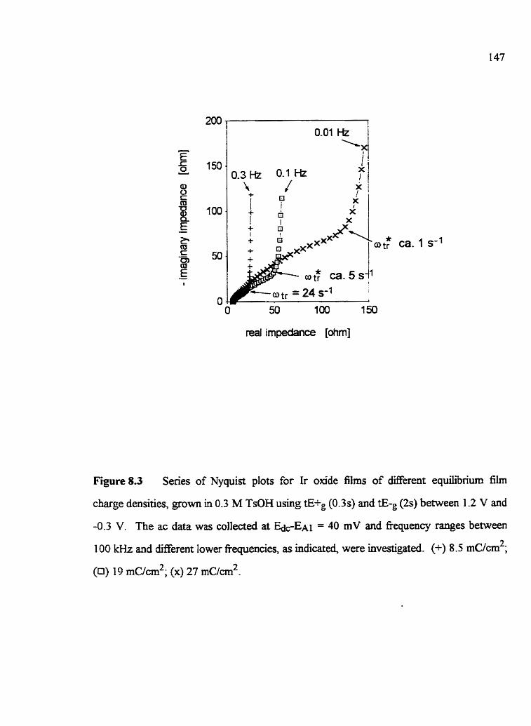
-0; Ca. 1 s-'
1
Figure 8.3 Series of Nyquist plots for Ir oxide films of dEerent equilibriurn fïIm
charge densities, grown in 0.3 M TsOH using t B g (0.3s) and tEwg (2s) between 1 -2 V and
-0.3 V. The ac data was collected at &EA~ = 40 mV and fiequency ranges between
100 kHz and different lower fiequencies, as indicated, were investigated. (+) 8.5 rnc/cm2;
(0) 19 m~lcm'; (x) 27 mc/cm2.

reai irnpedance [ohm]
Figure 8.4 Nyquist plot for a ca 27 d / c m 2 Ir oxide films gown in 0.3 M TsOH
using tE+g (0.3s) and tE-, (2s) between 1.2 V and -0.3 V. The ac data was coilected at
&EA~ = 40 mV and the fiequenq range between 100 kEh and 0.01 Hz was
investigated. The straight line represents the theoretical response of an ideal capacitor **
(i. e., -dZW/dZ' = m). ou is the transition to ideal capacitive response, indicaûng that d
Ir sites are reacted, and oW* is the transition to mainly capacitive response.

Figure 8.5 Dependence of %* on the inverse of the square of the equilibrium film
charge density (8.5 to 27 r n ~ / c m ~ ) for Ir oxide nIms grown between 1.12 V and -0.3 V in
0.3 M TsOH, using tEtg(0.3s) and tE-g(2s). The CD; values were extracteci h m the raw
ac data (collected at ~ E A I = 40 mV). The sotid line represents the best linear fit to the
experimental data

8.4.2 EQC anaiysis of the semi-infinite transport element, CPEr;
The EQCs shown in Figs. 7.3a to c fit the ac data for the ca 26 mc/crn2 ir oxide
films, gown using tE+g(2s) and tE-do.&), and tEî-g(2s) and tE-&s), as waç similady
found for Ir oxide films grown and studied in a range of acidic solutions (Chapter 7). The
constant phase element fàctor (ng) of the semi-infite transport dement QG, shown in
the EQC in Fig 7-34 was between 0.4 and 0.5 for these two Ir oxide fiims. This results in
dopes of the partly resistive-capacitive TML, seen in the experimental Nyquist plots
(Fig. 8.2a), of between c â 0.8 to 1. This indicates that the transport process during
oxidatiodreduction of these Ir oxide films deviates fiom planar conditions (planar
transport wouid yield a ng value of 0.5 [83,l3 11)- Eqs. (3.10) to (3.14) are derived for
pianar charge transport within &s of kineticaily equivaient redox sites and, therefore,
they do not describe aü of these Ir oxide films absolutely correctly (Chapter 7).
The n6 values were dso found to be influenceci by the poteutid pulsing times used
to grow the oxide films (an increase in tE-g yields smalIer ng values (< 0.5)). They dso
depend on the film redox state, as indicated by the increase of nc, of ca 14% when the
oxide film is changed fiom ca. 40% to 200% Ir(+IV) sites. These ciifferences in n~ may
indicate that the morphology of these oxide films depends on the growth conditions andfor
on the £üm state, and could be responsible for the observed kinetic ciifferences [132].
8-43 Dependence of aik on Ea,
Fig. 8.6 shows the dependence of In oe on the film redox state ( E ~ E A I ) for
ca 26 m~/cn? Ir oxide films grown in 0.3 M TsOH using different tE+g and tE-g valus.
This figure shows that the film kinetics change by c a 20 times when different potential
pulsing times are employed, consistent with the vw values (Table 8.1). The fact that the
CV characteristics of the main charge storage reaction of these three films are very similar

and that the same solution is employed to gow and exmine the films suggests that the
observed kinetic changes may be related to the oxide rnorphology (see below).
Figure 8.6 Dependence of ot, on the film state for ca. 26 mc/crn2 Ir oxide @ms,
grown and midieci in 0.3 M TsOH using Merent tE+g and tLp . (O) tEfg (2s) and
Sg (03s); (n) tE+g (2s) and tEp (2s); (A) tE+g (0.3s) and t L g (2s). AU Ir oxide films
were grown between 1.22 V and -0.3 V.
An almost linear dependence of In utr on and identical dopes of
16 i l / m v are found for the three oxide fXm$ grown using different fi+g and tE-g values
(Fig. 8.6), showing a strong dependence of the ïr(+Iü)Ar(+IV) reaction rate on the

fiaction of Ir(+W) sites in the film Also, the same species (either electrons or counter
ions) is IikeIy to be rate Iimiting for these three oxide film at all potentids based on the
a r m e n t that a change in the identity of the rate detennining species would likely not
yield the same dependence of on Edc-E~l at all Ek. Therefore, the rate limiting
species could be the electron, as it is generdy believed that, for the more reduced and
non-conductive Ir oxide fiIms, electron transport is rate determinhg [53,59].
8.5 Growth rate of ir oxide N m s in 0.3 M TsOE using diflerent potential
Fig . 8.7a and b show the dependeme of the equilibriurn film charge densities on
the t h e of film growth and the total number of o~datiodreduction pulses, respectively,
for Ir omde f3ms grown in 0.3 M TsOH solutions between 1.12 V and -0.3 V using
different tE+g and values (Table 8.1). It is seen that Ir oxide f3.m growth rate (per
minute) is faster when tE+g is increased and tE-!: is decreased (Fig. 8.7a). Fiç. 8 2 shows
that more oxidatiodreduction puises are required to grow the same oxide charge when
decreases (A W. a). Interestin&, for films grown using tEtg > tE-g (0 vs. a), the
same amount of q is grown per oxidation/reduction pulse, at least for the thinner Ir oxide
films (< ca 25 mc/cm2). In fact, the amount of oxjde f m e d in one oxidation/reduction
puIse was found to b e almost constant (ca 0.1 m U m 2 ) when tE+g(2s) and tE-&Hs),
and tE+s(2s) and tLg(2s). This is dso close to the maximum Ir oxide growth rate of
0.1 2 r n ~ l c m ~ per oxidatiodreduction s c q achievable at these electrodes [49].
Figs. 8% and d show the dependence of q on the total time vent at E-g and E+&
respectiveiy, for the same three filnis. It is seen that more time is required at E-g to grow
the same oxide charge when tE-, is Licreased (Fig. 8.7c), whereas, the total time spent at
E+g to establish the same q is s i m k for aii three films (Fig. 8.7d). in fbct, the total time

spent at E-g per unit oxide charge correlates with the nIm redox la'netics, as more time
spent at E-g results in slower Ir(+III)/Ir(+N) rates. This indicates th& at E-g, the Ir
oxide nIm properties are altered, leading to kinetic disadvmtages. It is most iïkeiy that the
Ir oxÏde sites closer to the Ir substrate are changeci at E-g as the film is then in the
reduced and non-conducting state and ail electrochemimy occurs at the substrate/fiim
interface. The formation of the kinetidy slow Ir oxide sites may be related to the HER
ocauring at E-g perhaps yielding some changes in the local pH. More time at E-g may
aiso reduce the oxide more completely, resulting in a decrease in the fÏlm water content
(Chapter 6).
It should be noted that, with time at E+g the Ir oxïde may be partly dissolved, due
ro the formation of soluble Ir(-VI) species [56]. This could resdt in the development of a
more disordered (rougher) Ir oxide nIm structure. Nso, several other factors could also
may be relevant at Etp, such as Hz0 consumption and alteration of the pH inside the
oxide via the OER [67, increased hydrolysis of the Ir oxide sites [18], etc.
8.6 SEM characterization of Cr oxide fdms
The thicknesses of the Ir oxide films studied in thik dissertation (oxides grown in a
range of acidic solutions andor using dBerent % and tE-g as descnied in Chapters 7
and 8) were determineci by SEM. The oxides were left immersed in the growth soiution
under open-circuit conditions until a steady-state OCP was reached. Ail OCP values were
close to EAI 2 10 mV, indicathg that they were ail in a simdar state (similar fraction of
Ir(+N)) when transfemed to the SEM vacuum chamber. Ir oxide films of large
eqdbrium charge densities (ca 80 to 100 rnUcrn2) were gown for these fi thickness
studies.

gmwth time [min.]
Figure 8-71
rapid film redox kineb'cs
3n int film redox kinetics
- hr slow film redox kinetics 1
8!0 0.1 0:2 0.3 0.4
total üme at Eg [min.]
Figure 8 . 7 ~
Q
oxidationlreduction pulse #
Figure 8.7b
total time at E+, [min.]
Figure 8.7d
Figure 8.7 Dependence of Ir oxide film gowth rate for films g o w n in 0.3 M TsOH
between 1.12 V and -0.3 V using different potentid pulsing times. (O) % (2s) and
tEa (0.3 s); (a) tE-tg (2s) and tEa (2s); (A) tE+g (0.3s) and t L g (2s). Fig. 8.7a shows the
equilibriurn fÏlm charge density (q) vs. the total time of growth; Fig. 8.7b as a fiuiction of
the number of oxidation/reductiun pulses; Figs. 8% and d vs. the total time spent at E-g
and Eig, respectiveIy.

Figs. 8.8a and b show srpical SEM views of ca 90 mc/cm2 Ir osde films, puise
(2s) g o w n in 0.7 M HClO4 between 1.2 V and -0.25 V, and in 0.4 M H ~ S O Q between
1.2 V and -0.3 V, respectively. For al1 Ir oxide films, extensive cracking is seeq which
has been suggested to be due to mm dehydration &ects [13] when s&ïciemly thick oxide
films are forrned. (Note that the extent of cracking depends on the solution, and tEtg and
tEg ernployed during growth, but for Ir oxide films of more than ca 80 r n ~ / c m ~ , cracking
was observed in every case.) The cracking of the oxide dows the film thickness
estimation to be made. AU Ir oxide tilms studied in this work were seen to be essentidy
unifom (k 5%), and independent of the growth conditions used. This shows conclusively
that the observed Werences in the II=(-IIi)k(+IV) reaction rate of up to ca 20 times
(Figs. 7.14 and 8.5) are not due to differing film thicknesses. It should be noted that
parallel in-silu eliipsometric studies of several Ir oxide fiIms &O showed (see below) that
they grow uniformly up to large film charge deflsities and that the thïckness is proportiond
to the equïli-brium film charge densisr.
In this work, an oxide film thickness of 14 nrn f 0.5 nm per m ~ / c m ~ passed in a
slow sweep CV was obtained. This agrees closely wàh results reported by Gottesfeld and
McIntyre [48]. Gottesfeld and McIntyre [48], who obtained a thickness of 295 nm for a
23 ~ C / C M ~ Ir oxide fïhq which was gown electrochemically in 0.5 M HzS04. This is
equivdent to 13 rn per rnc/cm2, whereas Pickup and Birss [l3] reported a thickness of
ca. 16 nm per rnc/cm2 for similar films, but rinsed with acetooe prior to the film thickness
estimation. Aiso, GottesfeId and Mchtyre [48] assumed that the charge passed to 1.0 V
(EAI -+ 0-3 V) yields the total number of Ir sites converted between Ir(+III)Ar(+W) state,
whereas in this work, the charge passed up to E A ~ + 0.22 V is assumed to yield the totai
number of active Ir sites, as was shilvly assumed by Pickup and Birss [13]. The dEerent
integration limits introduces some variation in the nIm thickness conversion calculation.

Figure 8.81 SEM side view of a ca. 90 r n ~ / c m ~ Ir oxide film gown in 0.7 M HCIO*
between 1.2 V and -0.25 V usîng the pulse (2s) method The image is obtauied using an
accderating voltage of 15 kV and a magnification of 10 kx. The bar shows that

Figure 8.8b SEM side vie* of a ca. 90 rnc/cm2 ir oxide film gown in 0.4 M HzS04
between 1.2 V and -0.3 V using the pulse (2s) method. The image is obtained using an
accelerathg voltage of 15 kV and a magniscabon of 10 k x The bar shows that
0.5 cm = 0.5 pm.

8-7 Ellipsometric studies of the effect of tE+g and tEg on ir oxide füm properties
Ellipsometry was employed to study the influence of tE+g and tEg on the
properties of Ir oxide films grown in 0.3 M TsOH. -411 of the data were collecteci with
time of oxide powth at 0.9 V (EdcE~l of 0.22 V), Le., when the oxïdes were in their
conducrive and colored state. The Ir oxide films were gown to h a i charge densities of
ca. 37 rn~ ic rn~ (tE+g (2s) and tEp (0.3s)), ca. 27 m ~ / d (Etg (2s) and tEa (2s)) and
22 r n ~ / c m ~ (tE-g (0.3s) and ( tLp (2s)). AU Ir oxide films were grown on an Ir foil
substrate (Chapter 2) and the CV characteristics were found to be s d a r to those for
films formed on Ir wires. This is shom in Fig. 8.9 for the typical example of
ca. 8.5 mc/crn2 Ir oxide films, go- in 0.3 M TsOH using different potential pulsing
rimes. The values of the anodic prepeak potenti-ai were aiso found to depend on the
potential pdsing times used to grow the Ir oxide films. E A ~ was found to shift more
anodicaily (same v and q) when tE+g was decreased and/or tEs increased (Fig. 8.9), Le.,
when the Ir(+III)llr(-ni') reaction rate is slower Fig. 8.9, Table 8.1). Al1 other
experimental conditions are described in Chapter 2.
Fig. 8- 10 shows the optical properties for the Ir oxide films gown in 0.3 M TsOH
using Merent tE+g and tEg values (Tables 8.2a and b). The typicai representation of
ellipsometnc data is used, plotting A vs. Y with t h e of growth, starting with the bare Ir
substrate. The relationship between A and Y is difFerent for al1 three films, indicating that
the properties of these oxides are influenced by both tE-g and t E g (see below). The
ellipsometric data of the three oxide films were b d to M a homogenous film rnodel.
Subsequent cornputer fitting yielded the values of the effective refiactive index (nctf) and
extinction coefficient (kcTc), as shown in Table 8 . 2 ~ This Table shows that the and
kcr values for ail three oxide film are ïnfiuenced by tE+g and tE-@ dthough the effect of
tE+g is very smdl. Lengthening the time at E-g decreases both n a and &. This

suggests that the degree of fiIm poro* (le., solution vs. oxide voIurne) is influenced by
these gowth conditions.
Potential vs. SSCE M
Figure 8.9 Typical CVs for m. 8.5 rnc/cnt2 Ir oade h s grown in ellipsornetric ce11
in 0.3 M TsOH and then cycled at 20 mV/s between 1.12 V and -0.3 V. The Ir oxide
nIms were grown and cycled using (-) tE+, (2s) and t B g (0.3s); (- - -) tE;p (2s)
and t L p (2s); (- - - -) ELg (01s) and tE1 (2s). Ellipsometric data were collected at
0.9 V vs. SSCE, as indicated.

Figure 8.10 Ellipsometric data collected during Ir oxide film growth by pulsing between
1.12 V and -0.3 V in 0.3 M TsOH using Werent eg and tE-g values. The data were
collected at 0.9 V vs. SSCE using red light of 632.8 nrn. (O) (2s) and tE-g (0.3);
(O) tEig (2s) and tE-g (2s); (A) tEig (0.3s) and tEg (2s). The fùil h e s represent the
fitted function, using the conditions in Table 8.2a. The data marked with an arrow
represent the bare Ir substrate and oxides of 22 (O), 21 (0) ànd 22.5 (A) rnckm2
equilibriurn film charge densities.

Table 8.2
Eliipsometric data for Ir oxide fim growth between 1-12 V and -0.3 V vs. SSCE in
03 M TsOH using different tIWg and tek as indicated
(a) Fitting A and V to a homogenous one phase mode1
Potential pulsing times used to
grow the Ir oxide lilms
+ average film thickness per mc/cm2 of equilibrium film charge density

(b) Fitting A and to a homagenous two phase model, using the Bmggemmn
lhitatio n
Potential pulsing times used to grow the
Lr oxide frlms
average tilm thjckness per rnclcm2 of equilibrium film charge density
Note that for the film thickness and %Vsolotion&dc eslkation shown
in Table 8.2b, an n of 2.6 and k of 0.8 1 are assumed for the oxide phase.
The tàa that the efipsometric data obtained for the Ir oxide films gown and
studied in 0.3 M TsOH can be fïtteci to a homogenous model indicates that the values of
and the nIm thickness are independent of the eqtdïbrïum film charge density.
This indicates îhat these oxide &s grow unifonly, consistent with the ac impedance
resdts (Sections 7-43, except for the Ir olade film gown using tE+&L3s) and
tEtEg(2s). The ac data for this particular fiIm suaests that kineticdly n o n - d o m film
sites build up during film gowth (Section 8.4). However, non-uniform film propemes
also becorne cfearly recognUabIe in the Nyquist plots for Ir oxide films of sufficientiy large
film charge deTlSities (> ca 20 rncicm2). Therefore, an insuffcient number of kinetically
Merent Ir oxide sites rnay have developed within the Ir oxide films studied here, grown
using tE+g(O.Ss) and tE-#s), so that, the n I m s appear opticdy homogeneous and
uniform. Neverrheless, the Ir(+m)/Ir(-IV) reaction rate is also influenced by the potentiai
pulsing times used for thin Ir oide film growth using tE+g(0.3s) and 1S-~(2s), dowing
the cornparison of the ellipsomebic data with the reaction rate of these oxide films.
The values obtained for g~ (Table 8.2a) are very similar to the r e M v e index of
0.3 M TsOH of 1 -36, indicating that these Ir oxide films are very hydrous, consistent with
the CV studies (Chapter 4). (Note that d data shown in Table 8.2a are highly
reproducible, since the nctf values deviated by I 0.01, ken < 0.001 and d < 0.5 nm per
rn~ / cm~ . ) The very hydrous cfiaracter of these oxides, and the fact that the ellipsornetnc
data fit a homogenous model, suggest that these oxide films consist of two phases7 the
oxide and the solution phase, which are homogeneously mixed together. S d a r results
have been reported previously for hydrous lr oxide nIms grown electroche~cally in
0.5 M H2SO4 [32,61].
In this work, die and values were found to depend on and tE-g
(Table 8.2a), suggesting that the solution vs. oxide volume depends on these growth

cond0Ïns. Previous CV results indicated that die thexmodynamic properties of the main
charge storage reaction are very similar for the three oxides (Section 8.4), thus alIowing
the assumption that the n and k values of the oxide phase are not influenced by tE+g and
tE-g. Therefiore, the eiIÏpsometric data for each of these oxides can be &ed to a
hornogenous 2-phase fh model consisting of two phases, Le., the oxide and the solution
(TsOH). It is aiso assumed that the voIume of the oxide phase at similar q is independent
of the potential puising times employed for oxide tilm gowth.
To examine these oxides and evaiuate the properties of each phase, a two phase
model cm be used in combination with the Bruggemann limitation (Chapter 3). Large
soluùon volumes of ca. 79 to 85% were assumed for the caiculations performed in this
work (Table 8.2b), refieaing the very hydrous character of these oxides. Previous
investigations ako suggested that sùnïariy formed Ir oxide films are very hydrous [40].
To fÏt the data, an n value of 2.6 was assumed for the oide phase, a value sirnilx to those
reported for other metai oxide films (an n of 3 has been reported for Pd0 [133]). The
overaIJ film thicknesses (Table 8.2b) were found to be çimilar (< 0.5 nm per r n ~ / c d ) to
those for the one phase model approach (Table 8.2a). it is again seen (Tables 8.2a and b)
that different tE-g and tE-g do not affect the film thickness sipifÏcantiy
(2 2 nm per rnc/m2). Consistent also with the SEM results (Section 8.5), changes in the
film thickness appear not to be responsible for the large kinetic differences observeci when
different potentiai pulsing times are employed for oxide film growth (Sections 8.3 and
8 -4)- The thickness of the wet and the dry i2m states are also very similar, as SEM studies
(Section 8.5) suggested that an Ir oxide of 1 rnc/crn2 yields a film thickness of 14 nm
This indicates that the Ir oxïdes do not notably shrink in thickness when they are dned in
air and/or vacuum. However, the- do lose H20, as seen by the presence of extensive
cracking (Figs. 8.7a and b).

These ellipsometric studies =est that the ir(+ID)/lr(-N) reaction kinetics and
the oxide film rnorphology could be reIated. For these Ir oxide films gram in
0.3 M TsOi-3, more time spem at E+% (1.12 V) appears to decrease the solution vs. oxide
volume a s weII as the fiIm oxidation/reduction kinetics, and vice versa, for an increase in
t L g (at -0.3 V). A Iarger solution vs. oxide voIume couid imply that fewer Ir oxide
fragments of large radius are formed. It has been shown that when the redox sites w ï t h
films are arranged in a cylindrïcal structure, then an increase in the radius of the cyhders
can increase the eIectrochemical reaction rate in a cubic marner when counier ion
transport is rate hiting [134]. Therefore, doubling the radius of the cyiinders could
introduce a dependence of the electrochemical reaction rate by a similar mgnitude as
observed here. However, the use of different potentiai pulsing times during oxide gowth
may also lead to other structural changes, and perhaps an increase in solution vs. oxide
volume wouid increase reflect the characteristic transport path length. This would then
also result in a decrease in the reaction rate when eiectron transport is rate Limiting.
8.8 FESEM studies of Ir oxide iiims
To gain m e r information about the morphoIogy of these Ir oxide flms, the
technique of FESEM was employed. However, this investigation is at a very eady stage
and ody preiiminary information has been obtained. Figs. 8.1 la to c show FESEM views
of a Ca. 30 r n ~ l c m ~ Ir oxide film puise (2s) gram in 0.4 M H2S04 between 1.2 V and
-0.3 V. At a mamiification of 5000 (Fig. 8.1 la), the typical mud-cracked structure of Ir
oxide films is seen, reflecting the dehydration of the film [13]. Figs. 8. I lb and c show
higher magiification views at 20 kx and 100 kx, respectively, of specific regions indicafed
in Fiçs. 8.1 1 a and b. Nanopores of ca. 30 nm diameter are recopzable in Fig. 8.1 1 c.
The oxide nanostructure is h imy ordered, as suggested by the Iinear pattern seen in Fig.

8.1 1 b. The pores visible at the oxide surface are coincident to the columnar structure seen
dong the cracks (Fig 8.1 Ic). This suggests that the pores penetrate the Ir oxide film, thus
dlowing access of solution deep into the Ir oxide f ï h Ah, the pores appear to occupy
at Ieast 40% of the totaI film volme, consistent with the very hydrous oxide film nature
iderred fiom other r e d t s [ci], and are of si* dimension to the oxide fragments.
Two Ir oxide films of ca 30 m ~ / c r n ~ were also grown in 0.3 M TsOH using
tE+8(2s) and tE-g(O.Ss), a condition for which the fïim oxidation/reduction reaction is
rapid, and t.E-&l.3s) and tE-s(2s), which r e d t s in a more sluggish nIm reaction
DifEerences in the oxide film structure were seen for all these oxide films, supporting the
suggestion thaî the observeci kinetic differences are due to Herent oxide morphologies.
A nanoporous structure was not visible for the oxide film gown in 0.3 M TsOH using
tE+d2s) and tE-&I2s). However, its surface was very rough, with oxide fiagnents of
ca. 100 nm width and ca 1 p length. The roughness is Iikely due to dissohtion of some
Ir sites accornpanying the OER [56]. Nanopores of ca 30 nm diameter were visible in the
second film guwn in TsOH, even though fewer and Iess ordered pores were recognizable
than found for the Ir oxide film grown in H2S04 (Fig 8.1 1). The surface of this film was
found to be very srnooth, suggesting again chat surface roughness is caused by the OER
Also, the Ir oxide f&s grown in H2S04 showed the most ordered nanoporous structure,
and the most rapid knetics of the three films investigated by FESEM. However,
additionai FESEM studies wilI have to be performed to better understand the reiatioaship
between the oxide morphology and the füm kinetics.

Figure 8.111 FESEM top view of a ca. 30 mlicm2 Ir aide film pulse 2s p w n in
0.4 M H?S04 between 1.2 Y and -03 V. An acceleraung voItage of 5 kV and
magilfication of 5 kx were used. The bar shows rhat 3 cm = 6 urn.

Figure 8.11b FESEM top views of a ca. 30 m~!crn' Ir oxide film pulse 2s gown in
0 4 kl H?SO4 between 1.2 V and -0.3 V. An acceleranng voltage of 5 kV and
ma-&cation of 20 kx were used. The bar shows thar 3 cm = 1.5 PM.

Figure 8 . 1 1 ~ FESEM top vkws of a ca. 30 rn~lcrn' Ir oxide Film pulse 2s p w n in
0.4 M H2SOs bem-een 1.2 V and -0.3 V. .h accelerating voltage of 5 kV and
magn3cation of 100 kx were used. The bars show that 3 cm = 200 nrn.

8.9 Sommary and Condusions
Thermodynamically very sidar, but kinetically different (up to 20 tirnes), Ir oxide
films were grown in 0.3 M TsOH solutions using different potentiai pulsing times. An
increase in tEtg andor decrease in t E g enhances the redox reaction rate, and vice versa
Al=, the rate of the fr(+m)Ar(-W) conversion reaction uicreases in an exponemiai
marner with the potentiai, as the Ir oxide films are made more conductive. This increase
with the change in film oxidation nate is independent of the gowth conditions, as has
been nmilarly found for Ir oxide films gown and studied in other acidic solutions. The
fact that the dependence of the rate of the reaction on Ede is so Simjlar for al1 films studied
and that no discuntinuity is seen with increasing potential does suggest that the same
species is rate Iimiting probably the electron. in both the more and les conductive film
States.
For Lr oxide £ h s which show slower oxidatiodreduction kinetics, a range of
kuietically different Ir sites build up during oxide gowth. The slow sites appear ta be
f m e d with increasinp time at E-g- The formation of kineticaiiy dBerent ir sites and
consequent differences in the Ir(+IIi)Ar(+rv) reaction rate very kely reflect differences in
the morphology of these oxide films. This has been supported using h-silu ellipsornetry,
which suggested that for Ir oxide films of larger solution vs. oxide volume, the rate of the
film oxidatiodreduction reaction is slower. Ellipsometry and SEN studies showed that
the füm thicknesses of these Ir oxide films are very similar, even when grown using
different conditions (solution anion and potential pulsing times). Therefore, the different
Kr(+m)fir(+IV) reaction rates are not due to different film thicknesses, and are more likely
related to morphological differences, possibly on the nano-scale.
FESEM studies have shown that pulse (2s) gown Ir oxide flms in 0.4 M HzS04,
(between 1.2 V and -0.3 V) consist of a highly ordered nanoporous stnicture, with pores

ca. 30 nm in diameter. This is the fïrst time that detailed evidence of the nanoporosity of
electrochemicdy grown Ir oxide films bas been obtained. The pores appear to occupy a
Large volume of the film and the oxide fragments appear to be of similar dimensions as the
pores. m e r preliminary FESEM results also showed that the nanoporosity and the
sudiace roughness of these oxide films is hfiuenced by the gowth conditions. More time
spent at Eip appears to roughen the oxide d a c e . Ah, the nanoporous structure may
be innuenced by both the solution anion and the potentiai pulsing times during growth
However, additional experiments are required to gain more certainty as to how the oxide
morphology is related to the observed differences in the Ir(+m)/lr(+IV) reaction rate.

CacriPTER9
KINETICS OF TEE Ir(+KIï)/Y+IV) REACTION RATE I'I DIFFERENT ACIDIC
TEST SOLUTIONS
Introduction
The redox kinetics of Ir oxide films fomed electrochemidy in acidic solutions
are iduenced by the growth conditions, such as the t h and tE-s values used, and very
Likely also the solution anion (Chapters 7 and 8). It has been shown that kinetic
differences of up to at least 100 times can be achieved for themodynamicdly similar Ir
oxide films, but grown usin; dBerent conditions. In this Chapter, the transport
impedance of Ir oxide films, grown and studied in a ranje of growth and test solutions
(different anions and concentration), will be investigated to address primarily the effect of
solution anions on the Ir(+III)/Ir(+IV) reaction rate. Key parameters such as the
transition fkequency (ou), the Iow fiequency resistance (Ru) and the low frequency
capacltance (Cr), are extracted from the raw ac data The influence of E- and E- and the
effect of time at the OCP in various test solutions on the Ir(SII)/h(+nr) reaction rate is
also investigated to establish whether the observed kinetic changes are due to the anion
and/or other experimental conditions. Also, the influence ofthe solution concentration on
the Ir(+ilr)/Ir(+lV) reaction rate will be briefly examineci.
Experimentai
In the work describeci in this Chapter, Ir oxide films were grown and studied in
2 M H3P04 and 0.16 iM &SO4 solutions. PrelUninary CV studies showed that several Ir
o d e properties wtiich could influence the film kinetics are identicai in these two
solutions. This assists in the interpretation of the EIS data (see Secbon 9.4.1). AU oxides

were emmersed at the OCP fiom the gowth solution and rinsed with ca 300 mL Hz0
befm they were studied in the other solution. Ca. 14 mc/cm2 ïr oxide films were grown
in either 2 M H3P04 or 0-16 M H2SO4 by pulsing (2s) between 1.2 V and -0.3 V. The
oxïdes were then cycied at 2 mV/s in the same solution, dowing rewvery of the fU film
charge. Some Ir oxide films were also lefi at the OCP (without potemial cycling), either in
the gr& or test soiution, before the ac and CV measurements were performed. The
solutions used to study the oxide nIms were changed fiequently (ca every 10 hours) to
avoid any concentration changes. Frequency ranges h m 100 kHz to 0.1 Hz at five
different Ede values (EA~, EA 1 30 mV and E A ~ + 60 mV) were investigated. The oxide
films were equilibrated at Ede for 1 min. before the ac data were colieaed. EIS
measurements performed at Merent EdC values showed that and RE are more strongly
iduenced by the test solution a d o r the potential cychg kits than by E& values within
30 rnV of each other. Kinetic parameters were found to be reproducible, even for newly
fomed oxide films employing the same conditions.
9.3 Data treatment
ot, and Rif values were extracted nom the raw ac data, as desmïed in Chapters 3
and 7, when the transition fiom semi-*te to finite transport conditions occurs. Cir
values were cdcdated from the experimental -2" values, when finite transport conditions
(seen as mninly capacitive behavior) were reached, using the following relaîionship and
assuming ideal capacitive behavior [83]:
Eq. (9.1)

Also, Ru, which is the s u m of the oxide film resistance and a contribution h m the semL
infinite transport term [93], is @en as folIows:
Eq. (9.2)
AU symbols in Eqs. (9.1) and (9.2) have their usual meaning.
9.4 Ir oxide f h s studied in acidic solutions of difFerent composition
9.4.1 CV characteristics
Fiç. 9.1 shows a srpical f m i y of CVs for an Ir oxide film grown in 2 M HfPO4,
and subsequenily cycled in 2 M H3P04 and in 0.16 M H2S04 between 1.2 V and -0.3 V.
Fig. 9.1 shows that E A ~ , ECI, E(u~)AI and E(in)ci, as well as the equilibrium film charge
density, are uninfluenced by the test solution The same values were also found when the
films were cycled between 1 -0 V and O V in the 0.16 M H2S04 test solution. These very
similar CV characteristics indicate that the Ir oxjde films are thermodynamidy very
similar when studied in these two solutions. This reduces the nurnber of Wors which can
influence the film kinetics F q s . 3.10 to 3-15}, as discussed in Chapters 7 and 8. Eao
(Fig. 9.1) was found to shift more cathodicdly with longer cychg h e s between 1.2 V
and -0.3 V in 0.16 M H2S04, whereas long term cycling in the same solution, but between
the restricted potentiai range (1.05 V and O V), affeçted EA, ody by a few mV.
It shouid be noted that the pH of the 2 M H3P04 and 0.16 M HzS04 solutions is
different. Despite this, EAI, which is known to shift with solution pH vs. the SSCE
(Eq. (3.3)), is found to be very similar (650 mV) in both solutions. This could reflect

different liqtxid junction potentiais in the 2 M H m 4 and 0.16 M &S04 solutions, but
may also reflect changes in the mVlpH response of the oxide ui the two test solutions.
+ wahcyclingii0.16Mi+SQ
betw een 1 2 V and -0.3 V
-0.4 O. O 0-4 O. 8 1.2
Patential m. SSCE M
Figure 9.1 CVs ofa ca. 14 rnc/crn2 Ir oxide film grown in 2 M H3P04 by puking (2s)
between 1.2 V and -0.3 V. The Ir oxide film was subsequentiy cycled at 2 mV/s between
1.2 V and -0.3 V in 2 M H3P04 (5 full srcles) and in 0.16 M H2S04 (total of 20 fiil1
cycles). (-) srn cycle in 2 M H3P04; (- - -) 5th cycle in 0.16 M &SOI;
(- - - -) 2 0 ~ cycle in 0.16 M &SO4.

9.4.2 EIS response of Ir oxide fims grown and studied in EQO4
After gowth, Ir oxide 5 s were first cycled between 1.2 V and -0.3 V in the 2 M
H3P04 gowth solution. During this process, ac data were collected as a f'unction of the
nurnber of oxidatiodreduction cycles, showing that a steady-state EIS response was
reached rapidly. Cr was found to be I O S rnF and and Rlr dues of 6 éL and 29 ohm,
respectively, were f o n d after > 1 cycle. Even so, in this work, Ir oxide films were first
equilibrated using 5 ftll cycles in the 2 M H3P04 growth solution before the innuence of
the test solution andor E+ and E- on their ac properties was investïgated.
9.43 The EIS response of Lr oxide films gmwn in &Po4 and then studied in
0.16 K2S04
9.4.3.1 Cydïng between 1 2 V and -0.3 V (extended potential whdow)
Ir oxide films, grown and equilibrated (5 fidl cycles) in 2 M appear
to reach constant values of ca 14 f1 aRer ca 20 cycles in 0.16 M HzS04 ("ïable 9.1).
This indicates that the film kinetics dmost double when these oxïdes are cycled in
0.16 M H2S04, rather than in the gowth solution (Section 9-42). Ru was found to
continue to decrease with longer times of cyding in the 0.16 LM H2S04 test solution,
sugesting that complete steady-state conditions are not reached, even aftw 3 5 cycles in
0.16 M H2S04. C r was found to remain essentidy constant in the two solutions and the
CV shape and equilibrium film charge density (Fig. 9.1) were not âffécted by cyciing in the
0.16 M H2SO4 solution.
The family of Nyquist plots shown in Fig. 9.2 for an Ir oxide film gown in
2 M &PO4 and then cycled in 0.16 M H2SO4 shows that the transport impedance (ZQ) is
altered ody after long t h e cyding, Le., fïIm properties relevant to the Ir(+iiQ'koIV)
reaction rate are only slowly altered in Uns test solution Also, a frequency dependence of

the siope of the partly resistive-capacitïve TML, seen at i n e is introduced as a
consequence of long bmes of potentiai cycling in 0.16 M H2SO4 pi=. 9.25). This
indicates that kinetically dinerent regions develop within the nIm.
Table 9.1
Influence of cyding at 2 mV/s in 0.16 M 82SO4 on the kinetia of rn. 14 r n ~ / a n ~ Ir
oxide fdms, putse (2s) grown and eqnilibrated for 5 cycles in 2 M 83PO4
(The Ir oxide films were grown and cycled between 1.2 V and -0.3 V).
estirnateci h m raw low fiequency ac data (below 0.5 Hz) using Eq. (8.1) and
asswniag ideai capacitive behavior.

real irnpedance [ohm]
Figure 9.2n Nyquist plots for ca 14 m ~ / c m ~ Ir oxide f i s , pulse (2s) gown and
equilibrated for 5 cycles at 2 mVIs in 2 M &PO4 (0)- The Ir oxide film was îhen cycled
at 2 mV/s in 0.16 M H2S04, between 1.2 V and -0.3 V, for (O) 5 cycles; (0) 21 cycles and
(x) 35 cycles. The ac data were collected at EAI = 0.65 V.

real impedance [ohm]
Figure 9.2b Nyquia plot for a ca 14 mc/crn2 Ir oxide film, pulse (2s) g o m and
equilibrated at 2 mV/s between 1.2 V and 4 . 3 V (5 cycles) in 2 M and then afcer
35 cycles (-0.3 V and 1.2 V) in 0.16 M H2S04- The Iiequency range shown (x) is for
1 00 kHz to 3 Hz. The full iine represents a theoreticai partly resistive-capacifive TML of
tiequency independent dope.

Cycling in restricted potentinl window (1.05 V - O V)
The innuence of E- and E- on the CV characteristics and kinetics of Ir
oxide films, Jrown in 2 M HsPQ, was also studied in 0.16 M HzSO4 in the restricted
potentid range of 1.05 V to O V. Fig. 9.3 and Table 9.2 show the Nyquist plots and Est
the ou, RK and Cr values, respectively, for this Ir oxide film as a hc t ion of cycle
numbers in 0.16 M HzS04- It is seen that the film properties are not strongfy altered in
these experiments. This is unlike cycling a sWar Ir oxide film in the same solution, but
between 1.2 V and -0-3 V (Section 9-4-34. In facf &er 35 cycles between 1.2 V and
-0.3 V in 0.16 M HzS04 a steady-state atr value of ca 1 4 s-' was reached (Table 9.1 ),
whereas aRer 46 cycles between 1 -05 V and O V, has decreased f h r n 6 8 to 4 s". In
paraIIel work [134], it has been shown that the equilibration of the bdk of the film is rapid
when transferring h m 0.5 to 0.1 iM H2S04, as seen by the CV properties of AiIC 1.
However, eqwlibration deeper into the nIm is much slower and requires cychg to
sufficiently anodic E+ values (2 ca 1.2 V). These resdts, and the Eict that cychg over an
extended potential window is required to alter the redox khetics of these films, suçgests
that Ir sites deeper in the film affect the redox kinetics of the entire film This would be
consistent with the gradud cathodic shat of EA, with time of cychg between 1.2 V and
-0.3 V (Section 9.4. l), as the A, sites are believed to be Iocated near the ir/& interface
[134]. This may then suggest that a carbodic shifi in EA, dso indicates that the reaction
rate of the entire film is enhanceci. In &CA, a correlation between E A ~ and the
h(+III)Ar(f IV) kinetics of the b d k of the fi has aiready been shown in Chapter 8.

Figure 9.3 'lyquist plots for ca 14 r n ~ l c m ~ Ir oide &s, pulse (2s) gown and
equilibrated (5 ful) cycles) at 2 mV/s between 2.2 V and -0.3 V in 2 M HjP04 (0)- This
was foIlowed by cychg at 2 mVis between 1 .O5 V and O V in O. 16 M H2S04; (A) shows
the 6Lh cycle and (x) shows the 46fi cycle. The ac data were collected at
Ede = E A ~ = 650 mV and the fiequency range between 100 kHz and 0.25 Hz is shown
here.

Table 9.2
Influence of cyding at 2 mVls behveen 1.05 V and O V on the Ionetics of ca. 14
mc/cm2 Ir oxide films pulse (2s) grown in 2 M H ~ P O ~ *
* (The Ir oxide films were grown and equilibrated (5 fidl cycles) between 1.2 V
and -0.3 V in 2 M H g 0 4 and then cycled at 2 mV/s in 0.16 M H2S04 between
1.05 V and O V. ALI potentials are @en vs. the SSCE).
** estimateci from the raw low frequency ac data, below 0.5 Hz, using Eq. (9.1) and
assuming ideal capacitive behavior
9-4.3.3 Ir oxide füms left nt the 0- in EitSO4
Ca 14 m~/& Ir oxÏde films were grown in 2 M H3P04 by puking (2s)
between 1.2 V and -0.3 V, and immediately after film growth, ac data in the gowth
solution were ~Uected. Then the Ir oxide films were transferred to and lefi (at the 0CP)
in 0.16 M H2S04 for 12 hours before EIS measurements were perfomed. The CV
characteristics obtained after the ac measurements in 0.16 M H2S04 suggested that no
film charge was lost and ~rpicai E A ~ and E c ~ (of 650 mV vs. the SSCE) and E ( ~ ~ ) A I and

E[in)ci (of 140 mV) values were fond. Alsq the redox knietics of these film are very
similar in the growth and the test solution, as the Nyquist piots in the two solutions
demonstrate (Fig 9.4). Similar ou values of 5 S' and only minor changes in the Rir
values (decrease of 34 to 33 ohm) are found when the nIm is left at OCP in
0.16 M H2S04- These results support those in Section 9.4.3.2, which indicated diat
alteration of the redox kinetics of the bulk of the oxide by the new test solution requires
cycling over a broad potentid window.
real impedance [ohm]
Figure 9.4 Nyquist plots for ca. 14 r n ~ / c m ~ Ir aide films, gown (pulse (2s)) in
2 M H3P04 between 1.2 V and -0.3 V, and Iefl in 0.16 M H2S04 at the OCP. (O) in
2 M H3P04 (immediately after film growth); (0) in 0.16 M H2SO4 (afler 12 hours at
OCP). The ac data were collected at E A ~ = 650 mV between 100 kHz and 0.1 Hz. (Note
that the red impedance axis for the raw ac data obtained in 0.16 M H2S04 has been
normalized tu account for differences in the solution resistance between the 2 M
CR, = 6 ohm) and the 0.16 M H2SO4 & ca. 7.5 ohm), to better compare the data

9.5 Ir oxide füms p w n in 0.16 M HzSO4 and then tested in 2 M H3PO4
EIS data were also colfected as fùnction of time of potential cycling in 2 M H3P04
for Ir oxide f h s groyn in 0.16 M H2S04- However, the characteristic CV features
showed that these oxides aged irreversiily (Chapter 10) ody after 5 potemial cycles
between 1.2 V and -0.3 V in the 2 M H3PO4 test solution. Therefore, a fâir cornpaison
with the results shown in Sedon 9.4 muld not be made. However, in a p d e I midy
[134], it was s h o w that the quilibration of the CV response, as gauged by E A ~ was
much faster when an oxide was transferred from the more dilute solution, 0.1 M H2S04
to 0.5 M H2S04, than vice vers& althou& the equilibration rate was again accelerated by
cycling to E+ values of 1.2 V.
9.6 Influence o f the test solution concentration on the kinetics of Ir oxide f h s
The EIS response for w 14 mc/cm2 Ir oxide films grown in 2 M H~POA and then
cycled in 0.5 M H3P04 between 1.15 V and -0.35 V, was ais0 studied. These parti-cular
E+ and E- values were chosen, since the EAI value of Ir oxide films is 50 mV more
negaiive in 0.5 M H g 0 4 than in 2 N HgO4. m e r CV characteristics (shown in
Fig. 9.9, such as the shape of peaks Al and Ci, were faund to be otherwise similar in
both of these solutions. A siight cathodic shift in EA, (vs. EAI) is observed (Fig. 9.5).
However, a steady-state EA, value is reached relatively rapidly in the 0.5 M H m 4
solutioq unlike the case in 0.16 M H2SO4 (Section 9.4.1 ).
CK values of 12 mF and 11 rnF are estimated fiom the raw ac data in 0.5 M H3P04
and 2 M &PO4 (Fig. 9.6), respective/ y, consistent with the similar equiliirium film charge
and CV peak shapes for this film studied in the two solutions (Fig. 9.5). Both ot, and RK
reach steady-state rapidly (c 5 potential scans), when cycled over the wide potential
window in 0.5 M (Fig. 9.6).

Figure 9.5 Family of CVs for a ca. 14 mc/cm2 Ir oxide film grown in 2 M H3P04 by
pulsing (2s) between 1.2 V and -0.3 V. The Ir oxide film was cycled at 2 mVfs in
2 M H3P04 (for 5 cycles) between 1.2 V and -0.3 V and subsequently at 2 mVk in
0.5 M H3P04 between 1-15 V and -0.35 V. (-): sLb cycle in 2 M H3P04;
(-- -): 5" cycie in 0.5 M H3P04; (----) 8a cycle in 0.5 M Hp04. The E scde is
defïned relative to E A ~ , since in 2 M H3PO4, E A ~ is 650 rnV, whereas in 0.5 M H3P04,
E A ~ is 600 mV.

reai impedanœ [ohm]
Figure 9.6 Nyquist plots for ca 14 mc/crn2 Ir oxide film, pulse (2s) gown and
equihbrated (5 full cycles) at 2 mV/s between 1.2 V and -0.3 V in 2 M H3P04. The Ir
oxide nIm was then cyded at 2 mV/s in 0.5 M H3PO4 between 1.15 V and -0.3 5 V. The
ac data were collected at E A ~ = 0.65 V in the 2 M Hg04 solution and at E A ~ = 0.6 V in
the 0.5 M H3P04 test solution. (O) afler 5 equiliibration cycles in 2 M H~POL (0) afler 5
cycles in 0.5 M H3P04; (O) afber 8 cycles in 0.5 M H3PO4.

The ot, values are again influenceci by the nature of the test solutions, as at E k = EAI, a
ou of ca 9 s-l is found in 0.5 M H90h whereas CD& is 6 s'l in the 2 M H j P Q soiution,
Similady, Rif is ca 35% smder in the 0.5 M H3P04 solution (ca 17 ohm) than in the
2 M &PO4 solution (ca 26 ohm), indicating that the ir(+III)Ar(+lV) reaction rate is
enhanced in the more dilute solution. The différent bulk solution concentrations codd
alter the solution concentration within the mide film, and the change in pH may also resuit
in different degrees of Ir oxide protonation These changes muid affect the
Ir(+III)Ar(+IV) reaction rate [28,122], wnsidered to be comolled by eIectron t d e r
between redox sites (Chapter 8) in these Ir oxide f i s .
9.7 Summary and Condusions
The reaction rate of Ir oxide films are different io solutions of different
composition than used for tilm gowth. However, in order to observe this, the potential
must be cycled over a broad potemial window for a sufficiently long period of t h e . This
is accompanied by the adjustment of EA, to its steady-state value in the new sohtion As
& sites are believed to be located deep in the film, possiily at the substratdfihn interface,
the observed kinetic aiterations as a consequence of cycling over a broad potential
window may be related to the equilrLbration of Ir oxide sites located deeper in the oxide
film. This also suggests that the redox kinetics of the buik of the hydrous Ir oxide film are
dictateci by the kinetics of film sites deep in the fiim.
The rate of the redox reaction is &O somewhat affected by the solution
concentration. This could be due to the changes in solution pK which may change the
degee of film site protonation or the extent of film hydrafion. However, the manner in
which these changes wouid affect the site-to-site electron transfêr rates in these nIms is
not yet clear.

C&GPTER 10
IRREVERSIBLE DIMINISEMENT OF TELE ir(tm)~+Bi) CHARGE
TRANSFER KIMCTICS WiLM AGMG)
10.1 introduction
Aguig of electrochemicaiiy gown Ir oxide films has been previously reported by
Birss and Elzanowka [135,136]. However, their emphasis waç mostiy on reversible film
aging, while the irreversible nature of this phenomenon is investigated in ttiis work Also,
their work [135,136] focused prharily on films grown in HNO3 and the influence of
transfer between solutions ( d y between adic and basic), whereas in the present work
the effect of the anion, film thicknessI sweep rate and other film properties achieved during
gowth in acidic solutions, was investjgated- Aging phenornena associated with Ir oxide
films have also been reported by Pickup and Birss [59]. They observed imevernible film
agng by the dirninishment of the ir(+m)/Ir(+IV) reaction kinetics for films studied in
HClQ&iC104 solutions.
In this Chapter, the phenomenon of irreversible nIm @ng will first be descnied
and defineci. This is followed by the evaluation of the nature of film agihg and a possible
explanation of the irreversible dirninishrnent of the Ir(+IlI)hf+IV) oxide kinetics will be
offered. Merwards, factors which either induce or prevent aging will be discussed.
Some focus wiU also be placed on the effect of Werent solution anions on film aging in
ternis of the proposed counter anion involvement during the conversion of Ir(+nI)/Y+IV)
oxide in acidic solutions 1621.

10.2 irreversible aging of Ir oxide films
Fig. 10.1 shows a typicai series of CVs seen during the irreversible m g of a ca
14 rnC/cm2 Ir oxida'de f ï h , grown in 0.6 M He104 by pulsing (2s) between 4 . 3 and 1.2 V
for 10 min. Immediateiy after the film is growq the potential is cycled at 20 mV/s.
Dunng the first cycle, a mirror-image type CV is s e e q as typicdy observed when Ir oxide
films are cycled at v < vq (Chapter 4). Howwer, Fig. 10.1 shows that, during the second
cycle, the charge in the Ai peak is reduced, and a new peak, Ai', appears at more positive
potentids. The appearance of the AI' peak indicates that the film propertïes aciiieved
during growth are being altered durinj subsequent potential cyciing. It is also notable in
Fig. 10.1 that the full film charge, seen best in the cathodic s i n , appears to decrease with
cycling time. However, film a g i 4 does not reflect a permanent loss of charge, since when
the potential is cycled at lower v, the complete charge cm be recovered. This suggests
that the vq of aged vs. wiaged films becomes smaller. Fig. 10.1 also shows that film
q-ng continues untii a steady-state CV is observed, in thk case, after ca 8 cycles.
Fig. 10.2 shows the CV recorded at a rate of 2 mV/s for an unaged film of
ca. 7 rn~icrn~ gown in HC104, in cornpanson with the CV for the sarne Ir oxide, but in
the partiaily aged condition. This film (Fig. 10.2a) was ca. 20%-aged (see below) in 8
complete oxidatiodreduction scans at a rate of 50 mV/s. The fact that the peak potentials
and haIf-widths of Al and Ci of the aged and mageci films are identical when cycled at
sufficiently slow rates indicates that the hydrous oxide itself is thermodynamiMUy not
altered during &ng. This suggests that wmplexation reactions and/or the irreversible
dehydration or hydration of a large fiadon of redox sites are not the kely ongins of the
irreversible aging of Ir oxides. This is contrary tu the explanation provided for a&
phenornenon reported for other films such as polymers [Il61 and hiCo oxide films [I 141,
which has been comected to changes of the film properties such as dehydration, which is

indicated fiom the changed potentials and haif-widths of the characteristic CV peaks.
0.0 0.4 0.8 1.2
Potential vs. SSCE M
Figure 10.1 Typical series of CVs seen dunzlg irreversible aging of a ca 14 mcicmt Ir
oxide film, grown and @ed in 0.6 M HClO4. The oxide film was grown by pulsing (2s)
between 1 -2 V and -0.3 V and then aged by cycling at 20 mV/s between 1 -2 V and -0-3 V
until a steady-state CV was reached after 8 complete potential scans. (-) first scan;
(- - -) 2nd scan; (-- ) 8& s c a n

Potential vs. SSCE M
Figure 102 Family of CVs at 2 mV/s for aged and -ed ca 7 Kim2 Ir oxide films,
g o w n and studied in 0.6 M HClO4- The oxide film was grown by pulsing (2s) between
1.2 V and -0.3 V and then aged in 7 complete oxidation/reduction scans at 50 mVls
between 1 -2 V and -0.3 V. (-) unaged ï r oxide; (-) ca. 20%-aged Ir oxide.

In this work, the sweep rate ernpioyed during the process of aging was found to
influence the number of cycles required to reach the final steady-state CV (Section 10.6)-
Therefore, to study the dependence of the rate of irreversr73le film aging on various factors,
the tenn 'A-rate' is introduced here. I t is defined ta be proportionai to the inverse of the
number of cyck required to reach a steady-state CV (scanning first anodicdly starting at
the open-circuit potentid, i.e., ca 0.68 V):
A-rate = I
no. of cycles required to reach a steady-state CV
Also, the degree of slm @ng ((%)-apd) is d&ed here as the inverse of the ratio
of the charge in peak AI in the aged vs. in the original unaged condition. Lu tfris work, it
was found that both the A-rate and the degree of k aging are influenced by v.
Therefore, the sweep rate used tu induce fh agi110 must always be stated. It shouid be
noted that ail @np phenornena studied in this Chapter are irrevershle in rrature. W
attempts to remver the original rapid kinetics of the Ir(+IIQ'hoN) reaction of the
unaged Ir olade were unsuccessfbl, once these fXms were s e d (Table 10.1 ).
10.3 Experimental details
The Ir oxide films discussed in this Chapter were generaily gown by pulsing (2s)
the patenthi between 1.2 V and -0.3 V in 0.4 M fIzS04, 0.4 M HNO3, 0.6 M I-ECL04
2 -M H3P04 or 0.3 M TsOH solutions. For films gown in the 0.3 M TsOH solution, E+g
was 1.12 V. The times of oxide growth and q m w e d fiom slow sweep rate CVs are
listed in Table 10.2. When Ir oxide films were grown using different conditions, this is
specified in the appropriate sdon of the text. E- and E- employed during subsequent
cycling were the same as E+g and E-g, unJess otherwise stated.
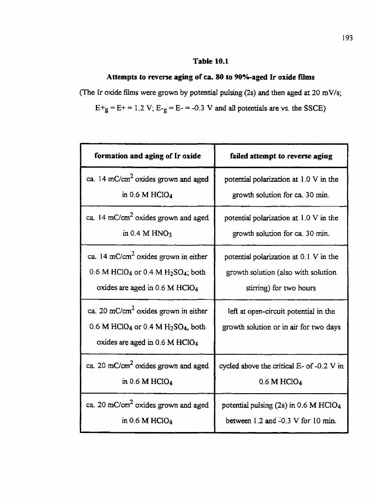
Table 10.1
Attempts to reverse aging of ca. 80 ta 90%aged Ir oxide füms
(The Ir oxide £ i h s were grown by potenual pdsing (2s) and îhen aged at 20 mV/s;
Etg = E+ = 1 -2 V; E-g = E- = -0.3 V and ail potentials are vs. the SSCE)
I formation and aging of Ir oride
I ca. 14 m ~ / m ' oxides gown and aged
in 0.6 M HCIO4
ca 14 m~/cm' oxides gown and aged
in 0.4 hd mO:,
ca 14 uCicm2 olcides Jrown in either
0.6 M HCLO* or 0.4 M H2S04; bath
oxides are aged in 0.6 M HCI04
ca 20 rnc/cmz oxides grown in either
0.6 M HCD4 or 0.4 M H2S04 both
oxides are e e d in 0.6 M HCQ
c a 20 rnc/cm2 oxides grown and aged
in 0.6 M HCI04
I ca 20 mC/cmL oxides gown and aged
failed attempt ta reverse aging
potentid polanZation at I -0 V in the
growth solution for ca 30 min.
potentiai polarization at 1 .O V in the
growth solution for ca. 30 min.
potentiai polarkation at 0.1 V in the
gowth solution (also wirh solution
shning) for two hours
left at open-circuit potenûal in the
growth solution or in air for two days
cycled above the critical E- of-0.2 V in
0.6 M H C I O ~
potential pulsing (2s) in 0.6 M HCIO4
between 1.2 and 4 . 3 V for 10 rnin.

Table 10.2
Conditions of Ir oùde growth used for mm agbg studies
@+g = 1 -2 V, E-g = 4 . 3 V VS. SSCE; t B p = t E - m 3 = 2 S)
x E+g = 1. L2 V VS. SSCE; tSg = 0.3 s
growth solution
0.6 M HCIO4
0.4 M H N 0 3
0.4 M H2S04
2 M H3PO4
0.3 M TsOH *
time of oride growth
[min.]
- 7 6
11
18
1
2
15
22
25
35
3 00
3 10
120
equüibrium füm charge
densiîy
[ m ~ / c r n ~ l
1
7
14
20
0.4
0.8
14
20
23
32
180
180
- 100

10.4 Cenerai characteristics of irreversible Ir oxide film aging
10.4.1 Ellipsometry of unaged vs. aged Ir oxide füms
Fig. 10.3 shows a typical set of ellipsometric data, with A plotted vs. V , for aged
and unaged Ir oxïde films grown in 0.6 M HClQ by potemial pulsing (2s) for a total Mie
of 1 0 min. and for data coilected at 0.6 V. In Fig. 10.3, the squares represent data
collected during the initial growth of Ir oxide in its still unaged condition, starting with a
bare Ir foi1 substrate. Mer 14 r n ~ / c m ~ of oxide film growth, the potential was then
cycled between 1.2 and -0.3 V at a rate of 10 mV/s to age the film (Ncles), sirnilar to
what was done in Fig. 10.1. It should be noted that complete (ca 90%) film aging was
achieved within 10 oxidation/reduction cycles and less thm 0.5% of additionai oxide was
formed durïnç the aging process.
The data coilected d t h g growth of the unaged film (squares in Fig. 10.3) couid
be fitted to a mode1 of a single, homogenous film, sandwiched between the electrolyte and
the he substrate (Fig. 10.4). A cornputer best-fit cdculation (solid line connmïng squares
in Fig. 10.3) yieIded an effective rehctive index ( n a ) of 1 -49, an effective extinction
coefficient (ka) of 0.06 and a final film thickness (d) for the 14 mc/cm2 Ir oxide of
190 ML This relatively Iow d u e of q g of 1.49 indicates that the fi is very hydrous,
possibly consishg of the oxide and the solution phase homogeneously mixed together.
This is consistent with previously reported results [31] (Chapter 8). The extinction
coefficient of 0.06 shows that this nIm is slightly absorbing, as the fb is in the partly
colored state at 0.6 V. The film thickness is aiso consistent with measurements obtained
from pnor S E M studies, which predicted a thickness of ca. 14 nm per aC/cm2
(Chapter 8), Le., a tbickness of ca. 200 nm for these oxide films.

Figure 10.3 Ellipsometric data culiected at Ede of 0.6 V using red tight of 632.8 nm
during growth and irreversible @g of Ir oxide fïIms studied in 0.6 M HCI04. A final
equilibnurn fih charge density of ca 14 rnc/an2 was achieved by pulsing (2s) between
1.2 V and -0.3 V. The oxide was then c â 90%-aged at 10 mV/s in 10 compIete potentid
scans between 1.2 V and -0.3 V. (a): data coIlected during growth of unaged Ir oxide
h; (O) data collected during different stages of fïim aging; (-) cornputer-best fi
mode1 for the growth of unaged Ir oxidê film

The data for the aged film could be fitted to either a single, homogeneous or a
rnultilayered, heterogeneous film rnodel. However, fitting the data to either mode1
requûes that the values of both and ken decrease. 'ïhjs wodd suggest that aged h s
contain more water than do unaged films and that they become thicker. It has been shown
previously that Ir oxide fdms are not altered themodynamicdly and that the total film
charge is not altered during aghg (Section 10.2). Therefore, the elIïpsometric results
indicate that water may have penetrated the fi via cracks, defects, etc., whkh wodd
result in some increase in the overail film volume and hence in the apparent film thickness,
d%d Fig. 1 O.4a).
(a) cracking withlli oxide and film swcUing
(b) cichminaiion of oxidc fragmcntsfromkmbstratc
Figure 10.4a Figure 10.4b
Figure 10.4 Possible physicai changes of Ir ofide films with aging based on
ellipsornetric results (not to d e ) .

The increase in water content could dso reflect the detachment of some oxide
fragments fiom the Ir substrate (Fig. 1 O.46}, which would aiso increase the apparent film
thickness (daged). This could occur without chan- the thickness of each h-ment- IIt
is &O seen that fewer oxide sites would be in direct ei&cal contact with the Ir submate
as a consequence of either cracking within the film or pamal delamination of oxide
kagments from the Ir mbstrate fFigs. 1 0.4a and b). Penetration of water via cracks in the
film vs. film delamination (Figs. 10.4a and b) cannot be distinguished frorn the
ellipsometnc data of Fig. 10.3.
10.4.2 Scanning Electron Microscopy (SEM) of unaged vs. aged fdms
SEM midies of a range of aged and unaged Ir oxide films have shown that a@ Ir
oxides appear to be less firmly attacheci to the Ir substrate in the SEM vacuum
environment and that some oxide W e a s are partiaily curled away korn the subsûate.
This is shown in Fig. I O.5a for a partiaily (ca 10%) aged 90 r n ~ / c m ~ Ir oxide film, gown
by potentiai pulsing (tE;g = 2s, tE-g = 0.3 s) and then cycled at 2 mV/s (1.1 2 V and
-0.3 V) for three complete oxidatiodreduction swis in 0.3 M TsOY and for a sidar
unaged Ir oxide fi (Le., not potential cycled after growth) (Fig. IO.%). The SEM
results are consistent with the fact that aged films can be easily rernoved from the
substrate, e-g., by the impingement of a jet of Hz0 and/or by physical jarring when
immersed in acid solutions, whereas unaged fiùns are much more stable and adherent to
the Ir substrate,
nie ttiickness of the aged and Lxnaged oxides fiagments (labeled as dmgd in
Fig. 10.4) were also estimateci f k m S E I for aged vs. unaged Ir aide f i s of sùnilar
equilibrium charge density. The resuits showed the thickness of the oxide fiagments to be
unaltered by açing, as similar thicknesses of ca 1.2 .n for both the 90 rnc/cm2 Ir osde
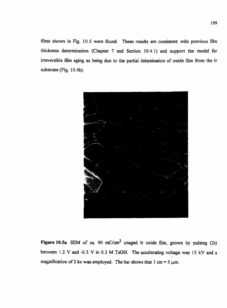
films shown in Fig 10.5 were found. 'ïhese r d t s are consistent wàh previous film
thickness determination (Chapter 7 and Section 10.4.1) and support the mode1 fur
irreversible film agihg as being due to the pamal delamination of aide film fiom the Ir
substrate (Fig. 10.4b).
Figure 1OSa SEM of ca. 90 mc/cm2 wiaged Ir oxide film. grown by pulsing (2s)
between 1.2 V and -0.3 V in 0.3 M TsOH. The accderating voltage was 15 kV and a
magüncation of 2 kx was empioyed. The bar shows that 1 cm = 5 prn
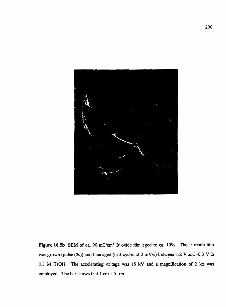
Figure 10.5b SEM of M. 90 mc/cm2 Ir oxide film aged to ca 10%. The Ir oxide film
was grown (pulse (2s)) and then aged (in 3 cycles at 2 mV/s) between 1.2 V and -0.3 V in
0.3 M TsOH. The accelerating voltage was 15 kV and a magnification of 2 lot was
employed. The bar shows that 1 cm = 5 p.

10.43 Growth of additional oxide in the presence of aged film
I t was f o n d that addition& unaged oxide can be fomed on an Ir substrate
covered with an aged film. This was observed for a ca 20 r n ~ / c m ~ Ir oxide nIm, grown
and aged in 0.6 M HCLO4. Mer the fiIm was ca 90%-aged in 7 complete
oxidation/reducûon scans at LOO mV/s, potential pulses (2s) between 1.2 V and -0.3 V
were applied in 0.6 M HC104 for 10 min The family of CVs in Fig. 10.6 shows that
additional unaged hydrous oxide has been fonned, even though the aged olode continues
to respond electrochemicaiiy as q e d Hm material, as ùidicated by the similar charge of
AI' immediately before and afker the new film growth. The newly grown oxide is unaged
and the full charge (QAI E QCI) can be recovered at 100 mV/s during the first scan after
its gowth. The electrochernistry and A-rate of l i 6 of the newly grown onde is very
similar to that fomd for Ir oxide tilms of similar charge density, but in the absence of the
probably overlying aged film (Section 10.7.1). M e r M e r potential cycling at 100
mVk, nIm aging is also observed for the newly formed Ir oxide (Fig. 10.6b). This couid
be consistent with the model of aging discussed in Sections 10.4.1 and 10.4.2, which
suggests that film agïng involves the exposure of the Ir substrate to the solution
Additional (unaged) oxide could then fom at the exposed substrate, thus dlowing newiy
grown oxide to e1ectrochemicaIly respond as if the unaged film were not present.
It is also seen in îhese CVs 10.6b) that the pseudocapacitive charge due to
the adsorption and desorption of atomic hydrogen (&ds/&) on the Ir submate is
uninfluenced by film &ng. This may not be inconsistent with the model of film aging
(Fig. 1 0.4), which suggests that film aging involves the exposure of more Ir substrate to
the solution. Q w a values were &rnated at v L 10 mV/s in 0.6 M HCL04 solutions
between 0.2 V and -0.23 V for a range of aged and unaged Ir oxide films. QH;lds values of
ca. 180 p~ /cm2 were found in all cases, in good agreement wiîh the Literature [63]. This

vaiue is aiso identical to the &ds value fond for the same Ir substrate d e r the
formation of one monolayer of compact Ir oxide. An increase in cm be achieved
only when the Ir substrate is covered with less than one monolayer of oxide and a maximal
QH* vaiue of 210 p~/cm2 is obtallied for an oxide-free Ir substrate [40]. This suggests
that the Ir substrates used in this work are covered with ca. 85 % of oxide, consistent with
other results [40,63]. These results also sugest that at least one rnonolayer of oxide
remains at the Ir substrate, even after film aging blocking the H adsorptioddesorption
reaction to a constant extent.
-0.4 0.0 0.4 0-8 1.2
PdwiGalvs. SSCE M
Figure 10.6a ABng (in 7 cycles) of a ca 20 rnc/cm2 Ir oxide film, fobwed by the
formation of additionai, ca. 14 rnc/m2 of Ir oxide. The Ir oxide films were gown
(pulse (2s)) and e e d at 100 mV/s between 1.2 V and -0.3 V in 0.6 M HClO4.
(-) umged ca. 20 mC/cm2 Ir oxide; (- - -) ca 90% (in 7 cyctes) aged ca 20
2 rnC/crn Ir oxide; (--) newly formed unaged ca 14 m ~ / d Ir oxide in the presence of
previously aged (90%) of 20 mC/crn2 Ir oxide film

Potenüal vs. SSCE M
Figure 10.6b Aging (m 7 cycles at 100 mVk) of a newiy formed ca 14 rncicmZ Ir oxide
film in 0.6 M HCL04 and in the presence of a ca 20 r n ~ l c m ~ previously aged Ir oxlde film
(see dso Fiç. 10.6a). (--) newly formed ca 14 mc/nri2 Ir onde in the presence of
ca. 20 rn~/crn~ aged ir oxîde; (-) after qïng (in 6 cycles) of ca. 14 r n ~ i c m ~ Ir oxide in
presence of ca. 20 r n ~ / c d aged Ir onde.
10.5 Electrochemicai lmpedance Spectroscapy (EIS) of unaged vs. aged films
Fig. 10.7 shows a typical Nyquist plot obtained for a 14 mc/cm2 unaged Ir oxide
film grown in 0.6 M HClO4. The ac data were gathered at 0.66 V, a potentid at which
the film consists of a neady equal of Ir(+III) and ir(+rv) sites. This Nyquist plot
(Fig. 10.7) is similar tu the EIS response for hydrous Ir o d e films shown in Chapters 7
and 8, where it was show that the simple cirait in Fig. 7 . 3 ~ could be fitted to this data
Also, it has been shown previously (Chapter 7) that., at intermediate fkquencies, the

conditions of counter ion and electron transport are semi-inhite in nature, wfiich red t s in
a partly capacitive and resistive transmission h e (TML), seen in the Nyquist plot as a
linear segment of close to unity slope (Fig. 10.7). At lower tiequencies, when sufl6cient
bme is allowed for every fiIm site to react, the transport becomes finite, r d t i n g in a
mainly capaciave TML (of dope approaching infiniSr), reflecting the pseudocapacitance
characteristic of Ir oxide films (Fig. 10.7). The transition between semi-infinite and finite
conditions is characterized by the transition fiequenq (a,), which is ca 75 s-' (12 Hz) for
this particdar unaged nIm (Fig. 10.7).
EIS was aIso performed with 14 mc/cm2 Ir oxide films Jrown and aged to
different degees in 0.6 M HC104. Figs. 10.8a (aü frequenties) and b (Iigher fkequency
data only) show typical Nyquist plots of a partly (ca 20%) aged Ir oxide film after five
complete oxidation and reduction cycles at a rate of 20 mVk. It is seen that the capacitive
film behavior can only be reached at a much Lower fiequency, Le., at ca 0.1 H z , for the
aged vs. the unaged film. This incikates that the kinetjcs of the Ir(+UI)fir(+IV) reaction
have diminished in the aged oxide films. Further, an addmoaal partly capafie-resistive
TML (slope of ca. 1.4 for this specific 61m) is recognizable in the Nyquist plot of aged
films in the 6equency range h m ca 12 to 0.8 Hz (Fig. L0.8b). This may indicate that
film aging introduces non-uniform transport properties into the system (see below).
The frequency characterizing the dope change between the two partly resistive-
capacitive TMLs (ol,') of the aged oxide f Ï h (Fig. 1 0.k) is ca 75 s-'. This is si* to
the ot, value f m d for the unaged Ir oxide film (Fig 10.7). Also, the slopeç of the partly
resistive-capacitive TMLs seen at higher fkequencies for the aged onde film (Fig 10.8a)
vs. for the unaged oxide film Pig. 10.7) are very similar (close to These results
may indicate that a portion of the aged oxide is responding as though Ï t were unaged.

real impedance [ohm]
Figure 10.7 Typical Nyquia plot of a ca. 14 mc/cm2 unryed Ir oxide grown and
studied in 0.6 M HCIO4. The Ir oxide was grown by pulsing (2s) between 1.2 V and
-0.3 V. The ac data were coilected at 0.66 V between 100 klHz and 3 Hz.

reai impedance [ohm]
Figure 10.8a
r d impedance [ohm]
Figure 10.8b
addtional partly resistiwpacitiw
TML
Figure 10.8 Nyquist plot of a pamally aged (ca 14 rn~/m~) Ir o*de film grown, aged
and studied in 0.6 M HCIO4. The Ir oxide nIm was grown by pulsing (2s) between 1.2 V
and 4 . 3 V and then aged at 20 mV/s in f i e cornplete oxidation and reduction cycles
between the same limits. The ac data were collected at 0.66 V k m IO0 k f h to 0.1 EIz
(Fig. 10.8a) and nom 100 ldlz to 5 Hz (Fig. 10.8b).

ElIipsometnc shidies have shown that the overd volume of açed films is likely to
be larger than for un@ films. This, together with the SEM data, suggests thth ir o d e
films may crack and curi away nom the substrate during @g. This wodd result in an
increase in the charmenstic transport path Iength (di) thmugh the film (Fig 10.4),
panicularly for Ir(+m)Ar(+IV) sites which are situateci at the edges of the curled
fragments wkch are located M e r away h m the Ir substrate as they protrude into
solution When v I vq (a L oo) aiI Ir oxide &es will have suffitient time to react and an
unaged CV response is seen. However, when v > vq (a > ou)), as is the case when film
aging is induced and the k(+Eï)Ar(+ïV) redox reaction process becornes transport
controlled, an ùicrease in di for those sites at the edge of the wled fragments of film will
increase the time required for those film sites to react 19931. Therefore, if film aging leads
to Ir oxide sites which are Located a greater distance &om the Ir substrate, this could
expiain the diminished kinetics of aged ir oxide films (Fig. 10.8). It shouid be noted that
other factors such as changes in film porosity, couid dso affect the hetics of these films
(see below).
The fact that an additional partly resistive-capadive T M ' (at lower fiequencies)
appears in the case of açed ir oxide films rnay be explaineci by the development of reg'ons
of n o n - d o m film thickness, as different oxide w e n t s curl and/or as cracking occurs
to a variable extent within the film. This wodd lead to a range of characteristic transport
path Lengths (as weii as a range of transition fiequencies) within the aged films, consistent
with this additional feature seen in the Nyquist plot (Fig. 10.8b). The EQC of aged Ir
oxide films rnay contain several ZtpPs, which, based on the suggested mode1 for film agi-
(Fig. 10.4), wouid be dectricdy connected in paralel, as shown in the EQC in Fig. 10.9.
Each Zlp is thought to represent oxide fkpents curled a d o r cracked to a similar
degee, whereas di frent nttp elements represent oxide fi-agments protruding to difFerent

extents aw ay h m the Ir n>b strate, and therefore have Merent characteristic transport
lenghs. The number of Ztp elements within this EQC wodd Vary, depending on the non-
uniformity of film m g . Note that the EQC in Fig. 10.9 reduces to the EQC assigned
previously for maged Ir oxide fïIms pig. 7 . 3 ~ ) when the transport prophes of electrons
and counter ions within the mm are unifom and therefore, suificiently descnied by one
Figure 10.9 Possible EQC for partly and fully conductive Ir oxide f i s which are a ~ e d
to different degrees. Any number of transport elements (ZV) can be used, depending on
the non-unifor* of film mg.

Zlp for asymmetrjcal and planar tmnsport of two mobile species is descnbed by
Eq. (3.1 O), as follows [93]:
Eq. (3.10)
At intf, when o >> - *,', Ztp (Eq- ( 3 - 1 0)) an be simpiifjed, as disusseci in Chapter 7, Le.: 4
Eq. (10.2)
2 2 (-Mso, note that te i li equals 1, when either electron or ion transport is limiting, thus
M e r sirnpiifjinç the relationship for Ztp (Eq. 1 0.1) and resulting in Eq. (1 0.2). F(Z) is a
proponionality constant which contai-ns dl fkquenq independent parameters and is
related to the semi-infinite transport elemem, C P k (Eqs. (7.4) and (7.5)).
Changes in F(Z) affect the mgnitude of the real and the imaghary impedance,
whereas changes in the t h e constant (r) (the value of which can be obtained ffom the best
fit EQC approach), Le., in:
Eq. (10.3)
influence the transition fiom semi-infinite to finite behavior, resulting in different ot,
values. An increase in r (due to a decrease in Dapp andior an increase in dl) results in a
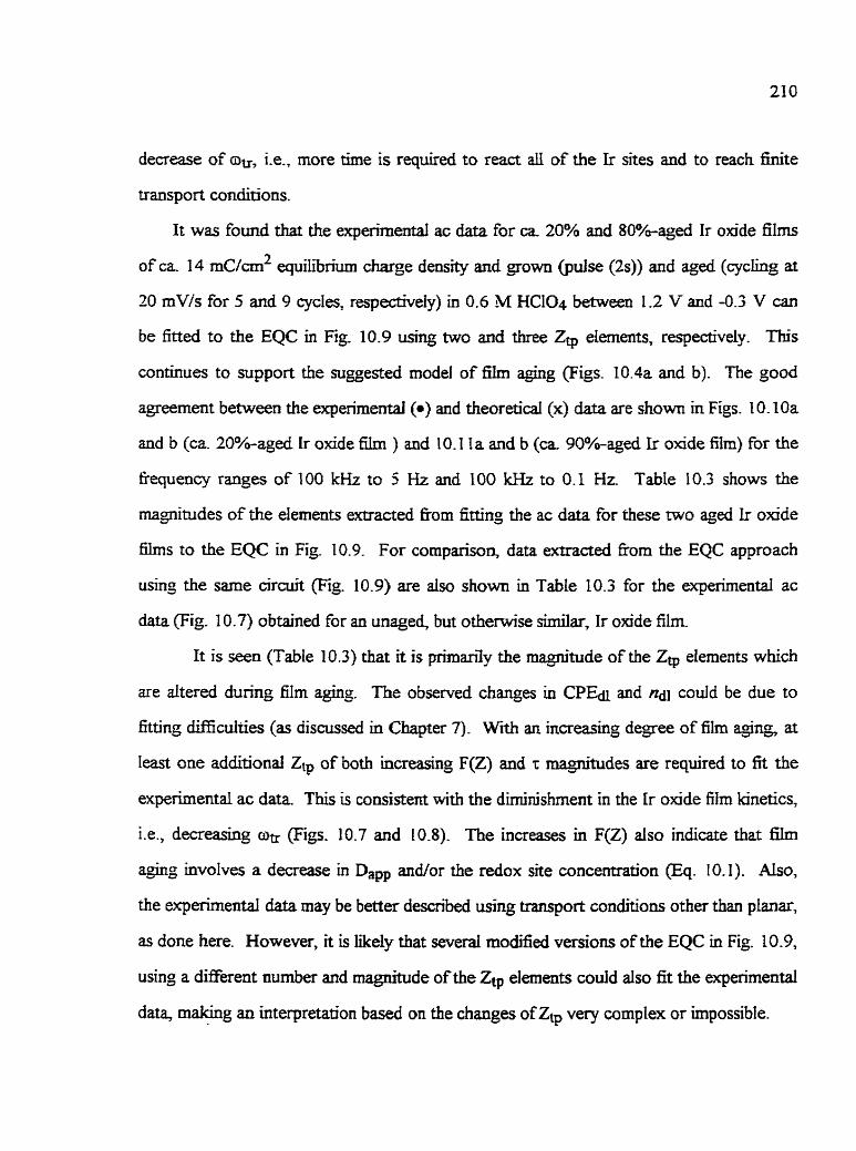
decrease of au, Le., more time is required to react all of the Ir sites and to reach hi te
transport conditions.
It was found that the experimental ac data for ca 20% and 80%-aged Ir oxide films
of ca 14 m ~ / c r n ~ equilibrium charge density and grown (pulse (2s)) and aged (cycling at
20 mV/s for 5 and 9 cycles, respectiveSr) in 0.6 M HClO4 between 1 -2 V and -0.3 V can
be fitted to the EQC in Fig. 1 0.9 us& two and three ZQ elements, respectively.
conhues to support the suggested mode1 of iïhn aging (Figs. 10.4a and b). The good
agreement between the experirnental (a) and theoreticai (x) &ta are shown in Figs. 10.10a
and b (ca. 20%-aged Ir olade 6ù1i ) and IO. I l a and b (ca 90%-aged Ir oxide film) for the
frequency ranges of 100 kHz to 5 Hz and 100 kHz to 0.1 Hr Table 10.3 shows the
magnitudes of the elements extracted h m fitting the ac data for these two aged Ir oxide
f i lms to the EQC in Fiç. 10.9. For cornparison, data extracted korn the EQC approach
usinp the same circuit (Fig. 10.9) are aiso shown in Table 10.3 for the experimental ac
data (Fig. 10.7) obtained for an unaged, but othemïse similar, Ir oxide film
It is seen (TabIe 10.3) that it is prhan7y the magnitude of the Ztp elements which
are altered dunng film agÙig. The observed changes in CPEa and na could be due to
fitting difficulzies (as discussed in Chapter 7). Wrth an increasing degree of film aging, at
Ieast one additional Ztp of botb inmeasing F(Z) and .r magnitudes are reqwred to fit the
experimentai ac data. This is consistent with the diminjshment in the Ir oxide film kinetics,
Le., decreasing oe (Figs. 10.7 and 10.8). The increases in F(Z) aiso indicate that film
aguig involves a decrease in Dam and/or the redox site concentration (Eq. 10.1). A h ,
the experimental data may be better descnbed usnig transport conditions other than planar,
as done here. However, it is ihdy that severai modified versions of the EQC in Fig. 10.9,
using a different number and magnitude of the Ztp elements muid aIso fit the eqerimental
data, m a h g an interpretation based on the changes ofZtp very cornplex or impossible.
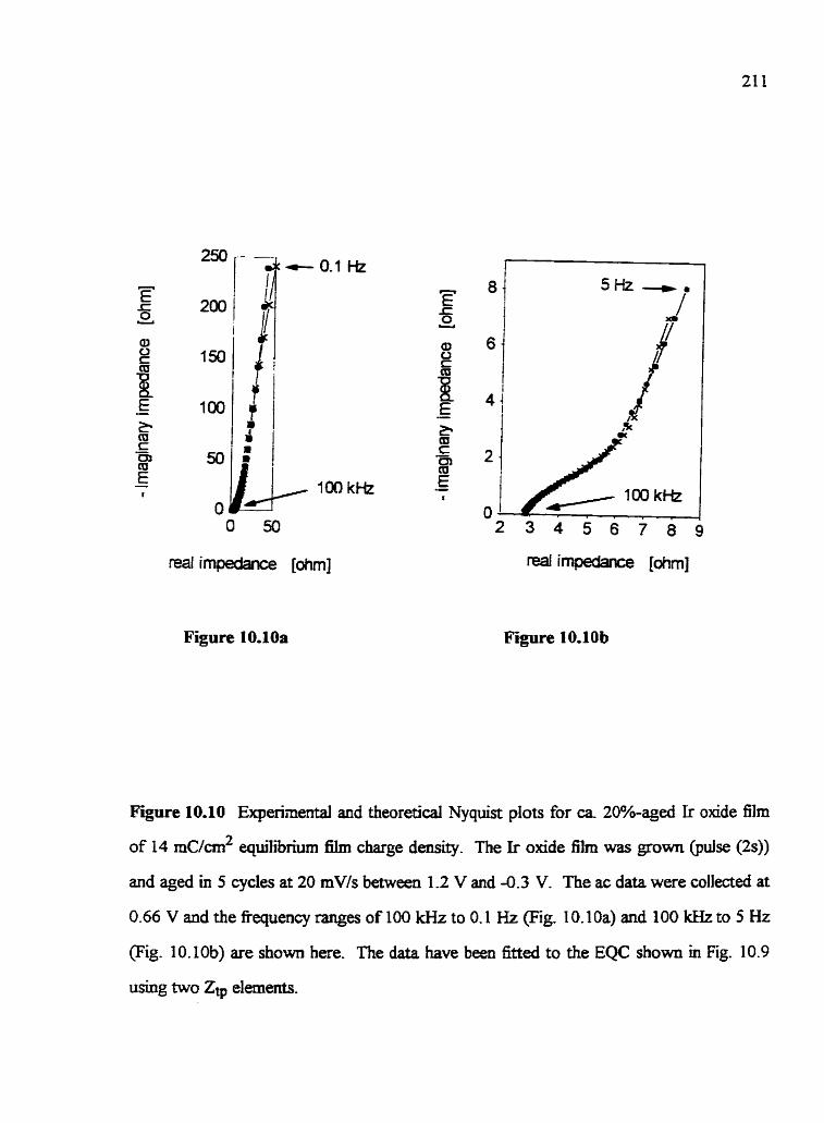
O 50
reai irnpedance [ohm]
Figure 10.10a
Figure 10.10 Experiinental and theoretical Nyquist plots for ca. 20%-aged Ir oxide film
of 14 mc/m2 equ11ibrium f ï h charge density. The Ir oxide film was gown (pulse (2s))
and aged in 5 cycles at 20 mV/s between 1 -2 V and -0.3 V. The ac data were collecteci at
0.66 V and the fiequency fanses of 100 kHi to O. 1 Hz (Fig. 1 0.1 0a) and 100 lcHz to 5 Hz
(Fig. 10.10b) are shown here. The data have been fitted to the EQC sbown in Fig. 10.9
using two Zv elements.

reai impe&nce [ohm]
O 4 8 12 t6 20
reai impedance [ohm]
Figure 1 0.1 1 b
Figure 10.1 1 Expenmental and theoretical Nyquist plots for ca 90%-aged Ir oxide film
of 14 mc/cm2 equilibrium film charge density. The Ir oxide film was go- (pulse (2s))
and aged in 9 cycles at 20 mV/s between 1.2 V and -0.3 V. The ac data were collecteci at
0.66 V and the fkquency ranges of 100 k $ b to 0.1 Hz (Fig. 10.1 la) and 100 kHz to 5 Hz
(Fig. 1 0. l 1 b) are shown here. The data have been fitted to the EQC shown in Fig. 1 0.9
using three Ztp elements.

Table 10.3
Magnitude of elemeots obtained using the EQC in Fig. 10.9 for unaged and aged Ir
oride f ims grown and aged in 0.6 M H a 0 4
(The Ir oxide films were grown by pulsing (2s) between 1.2 V and -0-3 V vs. SSCE and
aged by cycling at 10 mV/s between 1.2 V and -0.3 V for 5 (20%-qed) and 9 (80%-aged)
cycles. EIS data were collecteci at 0.65 V vs. SSCE usîng fiequency range between
100 rcHz and 0.1 Hz)
1 F(Z)z [ohm ilD]
large error

10.6 Effect of Ir orcide growth conditions on film aging
10.6.1 Minimum film charge density required to age a f h in a range of acidic
solutions
In this work, Ir oxide films were gown and then potential cycied in a range of
acidic growth solutions. The propensity of Ir oxides to aging appears to decrease
depending on the growth solution employed, as foilows: 0.4 M H N a > 0.6 M HC104 >
2 M H;P04 = 0.4 M H2SO4. This order has been assiped based on the fact that, Ir oxide
films gown in either 0.4 M H2SQ4 or 2 M H3P04 do not age? even when they are very
thick Oarge q), whereas minimal film charge densities are suficient to age Ir oxide films
grown and cycled in 0.4 M HN03 and 0.6 M HCL04 (Table 10.4). Although changes in
the growth conditions, such as variation in the pulsing times at E+g vs. E-B were found to
make ir oxide films grown in 0.4 M H2SO4 more or Iess prone to agikg (see below), this
is not observed for the gowth conditions (tEip = tE-g = 2s) selected to study the h s
listed in Table 10.4. Therefore, absolute statements concerning the effect of the solution
anion on Ir oxide 6 .h and stability canot yet be made. Ratheq a combination of
severd factors wiU be seen to be important, the solution anion, the potential Limits (E+, E-,
and tE-p), the pH of the solution, etc. AU of these factors together appear to define
the oxide properties and its propensity to aging, thus refleaing the very cornplex nature of
this process. However, the fact that @ng is seen when films exceed a certain charge
density (thickness) when grown and studied in 0 -4 M HNO3 or 0.6 M HClO4 (Table 1 0.4)
could suggest that fih and mass transport limitations are interrelated (see below).

Table 10-4
10.6.2 Effect of tE+g and tEg on the propensity of ir oxide fdm aging
The duration of the potential pulses applieà to grow Ir oxide films, tEfg and tE-g,
has also been fond to affect the tendency of an oxide fiim to age dllruig subsequent
potential cycling. ir oxide films were g o m and studied in various growth solutions,
0.4 M HzSOa 0.3 M TsOH, 0.6 M HC104 or 2 M H3P& at cycling rates of v = vcg.
Table 10.5 shows that a sufficient lengthening of t L g at fixed tE+g prevents film aging
altogether, whereas for a sdüciently large increase in tBg (tE-g constant), film aging is
induced, even for Ir oxide films grown in H2S04, TsOH and H3PO4 solutions. The
minimum tEtEg required to prevent film aging depends on the growth solution (Table 10.5).
This observed effect of tE-g on the susceptibility of Ir oxide films to q-ng may be related

rate of this reaction.
The influence oî
I growth solution

10.7 Effect of conditions employed after Ir oside füm growth on susceptibüitg
ta aging
10.7.1 The sweep rate used after oxide growth
Figs. 10.12 and 10.13 show the A-rates of Ir oxide films of two different film
charge densities, ca 14 rn~ /c rn~ and 20 mc/cm2, grown in HCIO4 and m03,
respectively, as a fiction of the sweep rate applied immediately after the films were
fomed. It cm be seen that the rate of film aging depends on the sweep rate apptied
during the aging process the film thickness (charge density) and possiily the anion of the
acidic solution. It is noteworthy that other factors, such as the potentiai cycling bits
used after p w t h , are dso found to be relevant to aghg (Section 10.7.2).
Figure 10.12 A-rate as a fundon of v for Ir oxide films grown (puising (2s)) and aged in
0.6 M HCIO4 between 1.2 V and -0.3 V. Each point represents a newly formed Ir oxide
film. (0) M. 14 mc/cm2 (vq = 50 rnV/s); (O) ca. 20 rnc/crn2 (vq = 100 mVls).

Figure 10.13 A-rate as a funaion of v for Ir oxide films grown (puking (2s)) and aged in
0.4 M HNOj between 1.2 V and -0.3 V. Each point represents a newly formed Ir oxide
film. (0) ca. 1 4 mc/cm2 (vq = 50 rnV/s); (O) ca. 20 mC/cm2 (vcq = 1 00 mV/s).
The fact tbat the sweep rate applied during the process of @ng influences the
A-rate tignificdy suggests that film aging may be related to the kinetics of the
Ir(;IZI)IIr(+lV) conversion reaction andior to the rates of the processes accompanying
th is conversion process. The influence of v on the A-rate, show in Fig. 10.12 for Ir
oxide films grown in HClO4, can be divided into three regions: very slow v's at which film
@ng does not occur, intemediate v's when the A-rate increases with v and rapid v's
when the A-rate decreases as v increases. In cornparison, the A-rate of Ir oxide f i s
grown in-HN03 show only the latter of these characteristics and the A-rate appean to

decrease in an expondai marner with increasing v (Fig. 10.13).
10.7.1 -1 Ir oxide fiùns grown in HC104
Fig 10.12 shows that film aging is not observed at alI when potentiai
cydiriç is &ciemly slow after gowth in 0.6 M HC104 consistent with the absence of
the Ai' peak. Film aging does not occur below ca 2 mVls for Ir oxide films of
ca 14 mc/cm2, whereas sweep rates lower than 1 mVls for Ir oxide t i lms of
ca 20 mc/cm2 were requûed to avoid aguig. This dependence of v on the susceptibility
of films of different thïcknesses to e n g may reflect a relationship between m a s transport
hnhtions wahin the oxide mm and aging- For these Ir oxide films, the rate of oxidadation
is known to be faster than for reduction [137], thus niggesting that at higher v, i 6 c i e n t
time is aIlowed during reduction to restore the film conditions dtered during oxidation. In
fa* although ouiy two data points are uivolved in Fig. 10.12, these very slow sweep rates
appear to be inversely proportional to the square of the equilibrium nIm charge density,
and therefwe also to di (Chapters 6 and 7). This is in agreement with the well bown
relationship between the time reqWred to react dl oxide sites and dl (Eq43.14)).
At intemediate sweep rat- Fig. 10.12 shows that tilm @ng occurs at v smder
than vq, when sufntient time is ailowed for dl oxide sites to be oxidized. (Note tbat the
vq values reported here are the highest sweep rate at wkch EAI is constant during the
estimated in the f2st cycle using several Ir oxide films of equal q. For the 14 and
20 r n ~ i a n ~ Ir oxide h s gown in HCLO4 the vq values are ca. 50 and 100 mV/s,
respectively) For these k oxide films, which age at a sIower rate, the cathodic charge
(Qci) passed between 0.9 V and 0.3 V is smaller than the anodic (QA~) at these sweep
rates. In facf the ratio of Qc;/QA~ increases with decreasing v and reaches unity at

sufficiently slow sweep rates when is not observed. For example, for a
ca 14 r n ~ l c m ~ Ir oxide film gown and cycled in 0.6 M HCIO1, Qci/Q~i ratios of 0.9 at
20 mVls, 0.9 5 at 4 mVls and 1 at I mV/s were found, in the first cycle m * n g fiam 0.2 V
in the anodic direction. This continues to suggest that mass transport limitations, perhaps
of counter anions, rnaybe are related to Ir oxide film aging.
At the more rapid sweep rates, a maximum A-rate is achieved when these Ir oxide
films are cycted at a rate slightiy p a t e r than vq, and then the A-rate decreases with
fûrther increase in v (Fig. 10.12). This niggests that the number of oxide sites converted
and the rate off311 aghg are related, suice at v Iarger than vq, uisuBcïent tirne is dlowed
for every Ir site present within the film to react. This wouId also be consistent with the
observed increase of the A-rate with the Mm charge densiv at a 5xed v.
10.7.1.2 Ir oude fïims grown in HN03
For Ir oxide films grown in HNO;, the A-rate (Fia. 10.13) was found to
decrease continuousIy as v inmeases. In fact, a srnail v below which aging is prevented
appears not to exist. This is different fkom the aging process for films grown and studied
in 0.6 M HCL04 (Fig. 10.12), even though the CV characteristics during irrevenrbie film
aging are very sim*lar in the two cases. This is seen in Fig. 10.14 for the process of film
erg of a ca. 14 nC/crnZ Ir oxide film grown and aged (15 mVk) in 0.4 -JI HN03. As
for the case of Ir oxide nIms grown and aged in HCQ (Fig. 10.1), an Ai' peak develops
and decreasing charge is recovered with continuous cycling at a constant v. Both of these
features indicate the irreversible diminishment of the film redox kùietics (Section 1 0.2).
The vq values for ca. 14 (and 20) mc/crn2 (unaged) Ir onde films, grown and
studied in 0.4 M m03 of Ca. 50 and IO0 mV/s, respectively, are very similar to the vq
values f m d for the Ir oxide films of shilar equilibrîum film charge density, but grown

and studied in 0.6 M HCD4 (Section 10.7.1-2). This indicates that the
oxidation/reduction kinebcs of unaged Ir oxide films of sunilar charge densities are
independent of the growth solution when formed in either 0.6 M HCIQ or 0.4 M HNO3.
Therefore, the observeci differences in the dependence of the A-raîes on the sweep rate
(Figs. 10.12 and 10.13) c m o t be ascribed to Ir(+UI)/Y+IV) readon rate merences.
0.0 0.4 0.8 1 -2
Potential vs. SSCE M
Figure 10.14 Typical series of CVs during agniç of a ca 14 m U m 2 Ir oxide nIm, grown
and cycied (1 5 rnVis) in 0.4 M HN@. The Ir orcide film was pulse (2s) gown and cycled
rid th between 1 -2 V and -0.3 V. (-) 2 cycle; (- - -) 3 cycle; (-) 7 cycle.

10.7.2 The 'critid potentiai cyding ümits' (E+ and E-) used after growth
nie iimas of potem-af cycling used after growth, Le., E+ and E-, have dso been
found to affect the rate and degree of film aging significantly.
E-: A suffichüy positive value of E- was found to either decrease the
A-rate or prevent film @ng completely. The criacal vaiue of E- depends on the solution
anion and the concentration of the soiution employed to gow and midy the oxide. For
example, a ca 14 r n h 2 Ir oxide film p w n in 0.6 M HC104 is not prone to agi% when
cycled at 20 mV/s to an E- limit more positive than -0.2 V, whereas the critical E- for Ir
oxide films of similar cbarge density, but gown and studied in 0.4 M HNOj (E+ in both
solutions was 1.2 V), is 0.1 V. These Ir oxide films were found to age at rates of ca. 1/14
and 111 2, respectively, when the potential was cycled to an E- of -0.3 V at 20 mV/s, uing
othemise sîmiiar conditions (Section I0.7.1). The fact that the critical E- is more positive
for Ir oxide films gown and studied in 0.4 M HNO3, vs. in 0.6 M HC104 incikates that Ï t
is more difficult to avoid aghg in HN03 soIutions (Section 10.13).
The followiog critical E- values were found for ca 14 r n ~ d Ir oxide films,
grown and then qded (5 and 20 rnV/s) to 1.2 V in a range of acidic solutions:
0.4 M H2SO4 2: 0.3 M TsOH: -0.8 V; 2 M H3P04: -0.32 V; 0.6 iM HC104: -0.2 V and
0.4 M HN@: -0.1 V. The aiticai E- values also depend on the potential puising times
used to gmw these oxides. In fact, nIni aging can be observed for Ir oxide films which are
grown and then cycled between 1.2 V and -0.3 V in solutions of 0.4 M H2S04, 0-3 M
TsOH and 2 M H3P04 when tE, is sufficiently decreased (Section 10.6.2). Similady,
film aguig is not observed for Ir oxide films grown and then cycled between 1.2 V and
-0.3 V in 0.6 M HCIO4 when tEog is sufficiently lengthened. These results show that the
critical E- vaiue shifts more cathodically with decreasing fi-,.


E+ vç. SSCE M
Figure 10.15 A-rate dependence on E+ (E- = - 0.3 V) for ca 20 rnc/cm2 Ir oxide &s
pulse (2s) gown and q e d at 20 mV/s between 1.2 V and -0.3 V in 0.6 M HC104. Each
point represents a newly gown Ir oxide film.
10.7.3 The oxygen reduction reaction (ORR)
Oxygen, which is produced at sufficientiy anodic E+ values, can be reduced (ORR)
at more negative potentials. The effect of the ORR on fih aging was bvestigated with
ca. 14 m ~ / d Ir oxide films grown in HC104. Immediately a f k gowth, either Nz or 0 2
was bubbled through the solution for 5 min., with the Ir oxide electrode lefi at the OCP,
close to EAI . A guiescent period of 15 s followed and then the &ntial was cycled at a
rate of 20 mV/s between 1.2 V and -0.3 V. Ir oxide films cycled in sohtioas of Iower 02
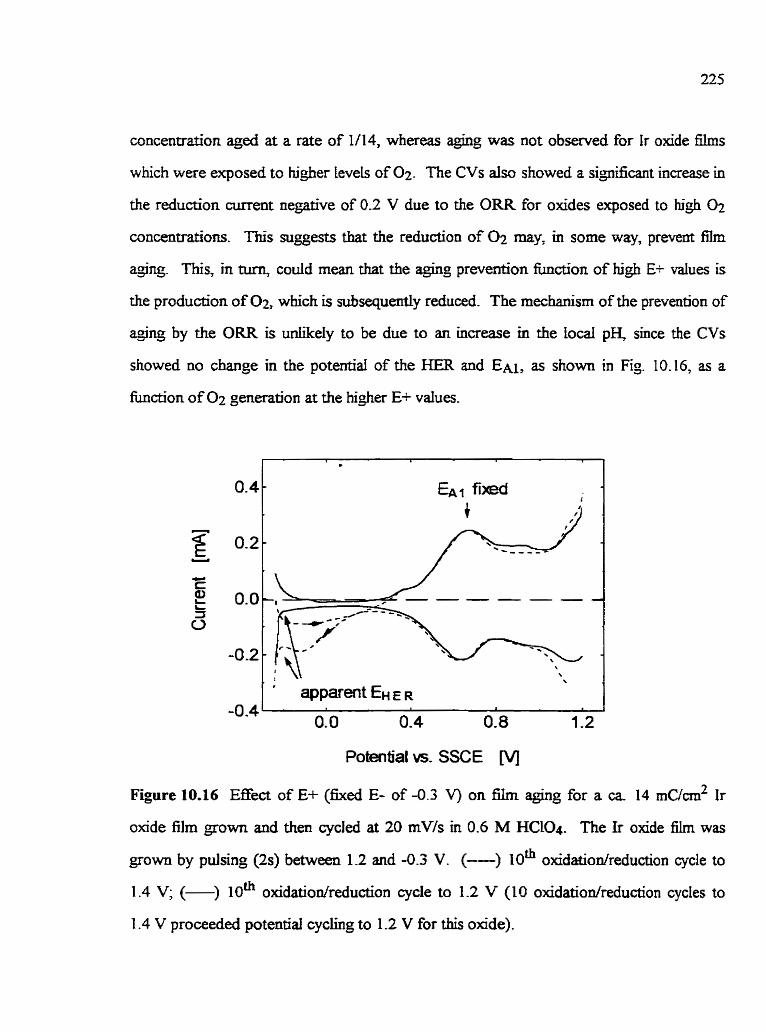
concentration aged at a rate of 1/14, whereas aging was not observed for Ir oxide films
which were exposed to bgher Levels of 0 2 . The CVs aiso showed a signincant increase in
the reduction current negative of 0.2 V due to the ORR for oxides exposed to hi& 0 2
concentrations. This suggests that the reduction of may, in some way, prevent film
aJing. This, in tum, codd mean that the agïng prevention hction of hi& E+ values is
the production of 02, which is subsequdy reduced. The mechanism of the prevention of
e n g by the ORR is uniikely to be due ta an increase in the local pH, since the CVs
showed no change in the potential of the HER and EN, as shown in Fig 10.16, as a
fiinction of 0 2 generation at the higher E+ values.
Figure 10.16
Potenfial vs. SSCE M
Effect of E+ (hed E- of -0.3 V) on film aging for a ca 14 niucm2 Ir
oxide film gown and then cycled at 20 mVis in 0.6 M HClO4. The Ir oxide film was
grown by pulsing (2s) between 1.2 and -0.3 V. (--) lom oxidatiodreduction cycle to
1.4 V; ( ) 1 0 ~ oxidatiodreduction cycle to 1.2 V (10 oxidatiodreduction cycles to
1.4 V proceeded potential cychg to 1.2 V for this oxide).

I t should dso be noted that the dirninishment of aghg with increasinç E+ is not
related to the increased formation of Ir(+VT)-qua compIexes [12]. This was tested using
a ca 14 mc/cm2 Ir oxide £ilq grown in Ha04 and then cycIed (20 mV/s) between 1.2 V
and -0.3 V in a 0.6 M HCLO4 solution e ~ c h e d with Ir(+VI)-qua complexes. This test
solution was prepared through the p h a l dissolution of an Ir ogde 5-1, grown and
dissolved (at 1.4 V for 30 min.) in 0.6 M HC104 prbr to the experiment. Ir &de films
cycled in this test solution aged at the same rate as seen in nomai oxide @ng
The rnechanism by which e n g may be prevented by the ORR is not clear. Three
possible pathways, each leading to similar end products, have been suggested for the ORR
at Ir metal substrates in acidic solutions [117,118]. The following is the most favored one
[l I7,118]:
Eq. (10.4)
Eq. (10.5)
Eq. (10.6)
It is seen (Eq. (10.6)) that H20 is a product of the O= and therefore, an hcrease in the
degee of film hydration may prevent film @ng, in support of a similar pn'or suggestion
[135]. As an agownent against this, howeveq previous investigations have show that film
a$ng does not occur when (unaged) Ir oxide films @rom and studied in 0.5 M H2S04)
are dried at elevated temperatures (200 OC to 500 OC) 1661 prior to potentiai cycling.

10.7.4 Effect of the test solution anion on Ir oxide fh aging
The rate of Ir oxide filrn aging appears to depend on the of the gowth
solution (Section 10.7. l), in which the oxide is usually also subsequenùy studied. This
provides support for the involvement of anions in the electrochemicai Ir(+iII)/lr(+lV)
conversion reaction a d o r suggests at least that Ir oxide filrn properties are si@cantly
influenced by the anion present d h g oxide growth To attempt to establish the role of
the anion more preciseiy, a.. 20 mc/cm2 Ir oxide films were growo in 0.4 M HzSOI and
then msferred and potential cycled in a range of other test solutions of different
concentrations andior composition (Table 10.6). The Ir oxide electrodes were emmersed
from the growth solution in their mixed ir(+IIï)/ir(-IV) state at the OCP, then rinsed
carefùlly with water (ca 200 mi. for ca 60 s) and finally immersed in the test solution at
the OCP. Table 10.6 shows that Ir oxide films were also transfemd, and subsequently
potential cycled, in either 0- 1 M HzSO4 or 1 M HzS04 sotutions. The influence of Et
and E- was carefdiy studied in both solutions to ensure that it was not the &ect of these
limits andior pH ciifferences which were being investigated.
The results in Table 10.6 show that the @ng of siiJfuric acid sown Ir oxide fdms
occurs rnost rapidly when transferred to test soIutions containing different anions (ClO4;
NO33 than the H2S04 growth solution. indeed film @g is not observed when Ir oxide
films, grown in 0.4 M H2S04, are transferred and subsequentiy potential cycIed in either
0.1 M or 1 M H2S04 solution. AIso, Ir oxide film agïng does not always occur when the
films are cycled in solutions containing different anions than empfoyed during growtb
This was observed for a ca. 14 rnc/cm2 Ir oxide film grown in 0.4 M HzS04 and then
cycled at 20 mV/s in 0.6 M HClO4. Fiim agirtg was found to occur in the test solution of
0.6 M HClO4 only when cycled to E- values more cathodic than -0.2 V (Table 10.6).
These resuits indicate that the anion does influence the propensity to irrevemile fiIm

agïng, especially when the oxide Ïs in its hlly reduced and non-conductive state, but that
the E- value is aiso important.
Table 10.6
Ir oside film aging during rycüng at 20 mVfs in a range of acidic test solutions
Al1 Zr oxide films were of ca. ?O mC/cm2 q~ilibriwn charge density and were pulse (2s)
gown in 0.4 M H2S04 between 1.2 V and -0.3 V. Ail potentials are vs. the SSCE.
E+/E- apparent E m
M M
apparent EOER

The effect of the solution anion on the Ir oxide film
229
properties was also observed
when ca 14 rnc/cm2 Ir oxide films were grown in a mked solution of 0.25 M HzS04 +
0.3 M HCL04 by potential pulsirg (2s) between 1.2 V and - 0.3 V. These oxides were
found to age rapidly in 0.6 M HC104 with a steady-state aged CV being reached after 3
oxidatiodreduction sans at 20 rnV/s, but they do not G e when mixed 0.25 M &SU4 f
0.3 M HClO4 and 0.4 M HzSQ4 solutions were used. This sugests that when HSO4- is a
component of the test solution, the films are less prone to a@ng in the presence of CLOi.
XRF studies of ca. 60 MC/G& Ir oxide films yown in the mixed solution of HzS04 +
Hel04 codkmed the presence of both species, Le., HSQ- and C1O4; within the a m
The integated areas of the counts for the S 1 s peak (2.2 - 2.4 keV) and CI 1s peak
(2.45 - 2.8 keV) peaks vs. the Ir 2p peak (8.8 -9.4 keV) peak were 0.17 and 0.147
respectively .
10.7.5 Aging prweotion after fiim growtb
In deoxygenated solutions, the effect of the E- value durÏng cycIing is ciearly
important. Cycling to potentials cathodic of the critical E- (Section 10.7.2) was found to
increase the A-rate, whereas it is s h o w here that constant potentiai polarization between
O V and 0.2 V is capable of preventing film depending on the other experimental
conditions employed. Also note that nIm aging cm oniy be prevented, but not reversed,
throuçh polarkation at O. I V (Table IO. 1) and constant potential polarkation in the more
conductive Ir oxide 6Im state (0.8 V) immediately after gowth, of not yet aged films, was
found not to prevent film aging in the following potential cycle. This aging prevention
method was seen for Ir oxide films (Table 10.7) which were cycled in the gowth solution
for one complete oxjdation/reduction cycle at a rate of 20 mV/s, first sweeping anodically
stirrting at 0.1 V. Then the reduced oxide films were emmersed, rinsed weil with Hz0 (ca
200 mL for 60 s) and transferred to a range of Mixent test solutions (solution 1,
Table 10.7) in which the potential was generally held at 0.1 V for 2 hours. Afteswards,
the potential was cyded between 1.2 V and -0.3 V in test solution II (Table 10.7) at a rate
of 20 mV/s util a steady-state CV was obtained.
Table 10.7 shows that film agùig cm be prevented when test solution I is
0.4 M H2S04, 0.1 M NDSAH or 2 M HflO4. When 0.6 M HCIO4 is used as both test
solutions 1 and II, ir oxide film aging is prevented only when the osde is aIso goum in
HClO4. Constant potential polarization at 0.1 V in HNO; did not prevent aging for Ir
oxide films gown in HNO;. In facf film aging had already o c m e d to a very large
extent (ca 75%) by the second cycle in HNO3. However, film aghg is effectively
prevented when an Ir oxïde 61m, gown in HNOj, is both polarized at 0.1 V and then
cycled in H2S04, thus indicating the relevant role of the solution anion in Ir oxide aging.
Xote that the latter Lr oxide film experienced one cycle to a more negative potential than
the critical E- value in the -3 solution, prior to constant potentid polarization in
H2SO4. In cornparison, Ir oxide films, grown and studied in HN03, are aged to a large
degee already in the second cycle if these same conditions are employed (Section
10.7.7.1).
The solution anion effect on film aging is M e r emphasized by the fàct that Ir
oBde films grown in HCIO4, but polarized in either H2SO4, NDSAH or H3PO4 (test
solution 1), age when they are cycled in HClO4 (tes solution II), but not when cycled in
H2S04, NDSAH or HSO4. Sunilariy, polarkation at 0.1 V and tben cycling in HC104
was found to induce e n g for Ir oxide films which would not normally age when cycled in
their gowth solution (e-ç., H 2 S Q and H3PO4).
AU of these results suggest strondy that the H2S04 NDSAH and H g 0 4
solutions prevent film aging more effectively than do HClO4 and m03. The marked

effect of the anion suaests again t h the anion is involved in Ir oxide film aging.
Table 10.7 Effect of polarbation at 0.1 V of u. 14 mc/cm2 Ir oride Bms p w n end studied in
a range of acidic solutions
growth
solu tioa
test solution 1
(hold E at 0.1 V)
test solution iI A-rate
estimated at 20 mVfs
Üt test solution II
I(# e y w - ' 1

10.7.6 Effect of solution agitation on Ir oxide fdm aging and on tbe oude kinetics
The rate and the degree of Ir oxide film aging was found to be reduced when the
bulk solution is stirred vigorously (either by bubbling N2 through the solution or drring
mechanicd1y) during the reduction of Ir(+IV) to Ir(+DI), whereas stimng at any other
potential did not affect the A-rate. Stirring the solution in the case of a ca 14 rnc/cm2 Ir
oxide film, grown and studied (20 rnV/s) in H m , reduces the A-rate by ca 30%. A@ng
is totdy prevented when the H C Q soIutioos in which Ir oxide films are Jrown and
studied (at v 5 vq), are stirred. is a permanent effect, as these films cannot then be
aged when subsequently oxidized and reduced in quiescent solutions. This indicates that
transport ikitations during oxide reduction are related to irreversible Ir oxide film mg, consistent with the observed A-rate dependence on v and the film thickness (Section
10.7.1). The anion is suspecteci to be the limiting species (see below), since Pickup and
Birss [49], and the resdts given in Chapters 5 and 6, all suggest that anions and protons
are both injected into the film during its reduction (Eq. ( 3 3 , and as the nature of the
anion has been shown to be relevant to Ir oxide nIm aguig throughout this Chapter.
Sturing during the Ir(+N) to Ir(+[lI) reduction process of Ir oxide nIms grown
and studied in 0.6 M HClO4 was aiso found to affect Q c ~ This is show for
Ca. 20 r n ~ / c m ~ Ir oxide films, grown and cycled (10 rnV/s) in 0.6 M HC104, in Fig 10.17.
The L- oxide nIms were reduced in either N 2 stirred (- or quiescent,
but deaerated, (- - - ) HClO4 solutions. [t is seen that nimng of the solution during the
film reduction allows the recovery of more cathudic charge. In fa* Q c ~ = Q A ~ when the
solution is stirred (- - - ), but, Q c ~ < Q A ~ when the solution is not stirred (-). This
would be consistent with a limited counter anion injection rate during film reduction, thus
then hindering the rate of the Ir(+IV) to ir(+III) reduction. Note that for Ir oxide films
not prone to aging, Qcl = Q A ~ and the film charge is stirring independent. Also, for the

latter films, electron transport is more likely to be rate deterrnining (Chapter 8).
Tnerefore, the hindered reduction of +ng-prone nIms (Fig. 10.17) could suggest that the
nature of the rate Iimiting species during the Ir(+IV) to k(+m) readon is Werent for
films which are prone to aging vs. those which are not-
Potential vs. SSCE M
Figure 10.27 Effect of -ng during the Ir(+IV) to Ir(+iII) reduction on the CV for c a
20 mC/crn2 Ir oxide films, gown and studied between 1.2 V and -0.3 V in 0.6 M HC104.
The Ir oxide film was pulse (2s) grown and then cycled at 20 mVls. ( ) soiution was
stirred with N2 between 1.1 V and 0.3 V; (- - - -) nIm oxidation and reduction occurred in
a quiescent, but deaerated sulufion. Each CV represents a newIy gown Ir oxide film.

10.8 Summary and Conciusions
An irreversible aging phenornena of electrochemically grown Ir oxide films,
reffecting the diminishment of the Ir (+Iü)/lr(+[V) charge trander kinetics. bas been
investigated. Slow sweep CV studies showed that @g does not alter the thermodynamic
propertjes of the film and that no loss of film charge occurs. ElIipsometry and S E M
investigations M e r showed that irreversible aging of Ir oxide films in the growth
solution involves an increase in the content of solution in the film and an increase in the
overdl fi thickness (which dehes the opticai properties ofthe oxide). This may occur
throuçh the detachment of oxide fragments from the Ir substrate andor cracking (and
hence swehg) of the oxide, thus reducinç the number of oxide sites in direct e1emica.i
contact with the Ir substrate. As a consequence, the characteristic transport path length of
the aged oxide and the time required to fûiIy react aii Ir sites is increased, seen as
diminished k(+III)Ar(+rV) charge transfer kinetics. It is likely that oxide fragments
promde to Werent degees into the solution away from the Ir substrate, thus introducinç
a range of characteristic transport lengths. This is consistent with the best fit EQC for
aged Ir oxide films, consistinj of several transport elements describing elecmn and
counter ion transport within the oxide film, and each element is of a different magnitude.
Irreversible Ir oxide film agïng is only observed as a consequence of the film
oxidation/reduction under specific conditions. It was found that Ir oxide films are made
Less prone to aging by solution stimng during film reduction and by cycling to potentials
positive of a critical E-. The latter eEect depends on severai conditions used to grow and
study these oxide films. The rn-on of the growth and test solution appears to be relevant
to film W g . This suggests that mass transport limitations of anions, which are involved
as counter anions in the electrochemicai fiim reactiou, increase the propensity of Ir oxide
films to aging. Constant potential polarizaàon in the reduced, non-conductive state of the

film, but more anodic than the critÏcd E-, cm prwent mm depending on the anion
of both the growui and test solution. Afso, polanration at O. 1 V in H2S04 NDSAK and
H3PO4 solutions appear to prevent film aging more effectively than in HC104 and HN03
solutions. Alsq the reduction of oxygen on these electrodes may prevent film @g, even
though the effect of the ORR on the Ir oxide film properûes is not permanent, Le., film
*ng is only prevented when oxygen is continuously reduced at these electiodes. Film
q-ng can also be prevented through the selection of appropriate gowth conditiocs,
specifically when tLg is SUfficiently Lengthened.
The fàct tbat irreversible aging of Ir oxide nIms requires cycling to nifficientiy
cathodic potentials (below the criticai E-) suçgests that nIm aghg and the formation of
'new' hydrous Ir oxide film are related. It is possible that the newly formed (at E-) Ir
oxide is not cross-lmked well to the previously formed, overiyÏng hydrous Ir oxide f2mi
thus resulting in loss of good electncal contact. The propensity of Ir olode films to
depends on the anions present in solution, and therefore, anions may assist in the
formation of cross-linked hydrous Ir oxide. Anions may also avoid the formation of
Ir(+IV)-qua complexes, which are Hz0 soluble [12], andor reduce lateral interactions
between Ir oxide sites, as bas been observed for the formation of oxide films on
Au a d Pt [139].

CaAPTER I I
CONCLUSIONS AND SUGGESTED FUTURE WORK
1 1.1 Conclusions
(1) Hydrous Ir oxide fÏ.Ims can be gown in a range of aqueous acid solutions,
including organic atids composai of large anions (ir oxÏde films were grown in TsOH and
W S A H for the first time in the present work), using s ~ i l a r approaches. Their
equilibriurn (slow sweep) characteristics are very similar, and do not reveal the differences
in their properties which becorne detectable through other tests. Also, SEM studies show
h t the relarionship between (dry) film thickness (per equilibriurn nIm charge density) is
drnost independent of the growth solution used.
(2) All of the Ir oxide films studied here show excellent capacitive
characteristics, as long as the perturbation rates are sficientiy low. Film capacitances of
> 0.1 ~ / c r n ~ are readily obtained.
(3) For the fkst tirne, clear evÏdence for the nanoporous structure of
electrochemically fomed, hydrous Ir oxide fïhs has been obtained, using the technique of
FESEM. The gowth conditions appear to in£iuence the oxide morphology, and Ir oxide
films grown in 0.4 M H2S04 show a highly regular structure on the 30 nm scale, with the
pores occupying c a 20 - 40% of the film volume.
(4) The present shidy has c o n h e d that the super-Nedan shift of the peak
potenbal with pH of electrochemicdly formed, hydrous Ir oxide films partly refiects the
involvernent of counter anions in the nIm redox reaction in acidic solutions, as has been
suggested by earlier workers. However, the -68 mV/pH response in suifuric acid solutions
of pH ca. 0.5 to 1.5 suggests that the ratio of ;inions involved per Ir site is smaller than
predicted in previous studies (a. 0.15 HSO4- instead of ca. 0.5). EQCM studies also

suggest that anions serve as charge compensating species in the [r(+m)/Ir(-[V) reaction,
as well as that the acidhase character of the Ir oxides is not strongly Îduenced by the
identity of the solution (C104-x HS04-, N033.
(5) A detailed anaiysis of the EQCM data shows that Hz0 is also exchange4
apparently non-hearly with potential, as the film is oxidized and reduced. In fact, d
appears that water injection/expuIsÏon ocnirs pred~~nandy in the reduced fom of the
film, and less so in the oxidized form, and is slower d~nng film reduction than oxidation
Steady-state H20 injection/expulsion at al1 potentiais may be reached at very slow sweep
rates (v v~).
(6) The ac response of Ir oxide films is ofien consistent with to the simplest
fom of an electncal circuit desaïbing a faradaic reaction in a porous ma& This EQC
contains a single transport element, representuig semi-infinite and hite transport of
elec~ons and conter ions withi-n the film. The fact that a singe transport element
descnbes these nIms indicates that the transport properties are uniform. ir oxide films of
unifonn transport properties, Le., constam Dam cm be grown to large thicknesses (r 700
nm) in a ranp of acidic solutions.
(7) Impedance studies have reveded very clearly tbat the onset of diaisional
Limitations, when the transport conditions of the f3.m change fiom finite to semi-infinite,
depends very much on the growth condaions employed. The kinetics of the
Ir(+m)lIr(+rv) reaction cm be altered by up to 100 tirnes, depending on the gowth
conditions (solution, potentiai pdsing times, etc.) employed.
(8) An increase in tE+g enhances the rate of the nIm redox reacbon, whereas
an increase in tEp reduces this rate. EIS studies also showed that more time spent at E-g
during gowth of the oxide results in the development of kinetically different oxide sites
within the film. Eiiipsornetry studies also indicated a relationship between the oxide

morphology and the £&II redox kinefics, Le., that Ir oxide f i s of larger solution to oxide
volume are electrochemically converteci at a slower rate, and vice versa This indicates
that dserent oxide morphologies, probably on the nanometer sde* are responsible for the
up to 20 times different reaction rates resuitirg when different potentid puisinç times, but
othenvise the same growth solutions, are employed.
(9) The kinetics of the redox reaction of Ir oxide füms increase in an
exponential rnanner as the film is made more conductive at higher Ede values. The fàct
that this expondal dependence of the knetics on the potentiai is continuuus and similar
for ail films suggests that the same species is rate iimiting at ail potentials and in dl cases.
Based on the prior fiterame, it is suggested that electron transport is the sbw step in the
redox che- of these films.
(10) The redox kinetics of Ir oxides are changed as a consequence of potential
cycling in different test solutions than used for nIm growth. However, this requires
cycling over a wide potential range* such that the growth solution is M y expelied at E+
and the test solution is injected at E-. The resuits suggest that Ir sites Located deep in the
film are o d y slowly equiliirated with the test solution, and that those sites wi dictate the
redox kinetics of the entire hydrous Ir oxide film.
(1 1) Ir oxide films are susceptible to an irreversible aghg phenornenon, which
has several negative chat-acteristics, Le., a loss in film kinetics and a loss in film stability.
Ir oxide films can be made prone to aBn& or &g can be prevented altogether,
depending on the gowth and test solutio~s employed, the potential puising times used for
film growth, and constant potential polarization in the reduced state in certain solutions
(preferably H2SO& M)SAH or H3P04). The initiation of film aging requires potentid
cycling to sufficiently negative potentials, below a criticai E-, and may be related to the

mechanism of çrowtfi of hydrous Ir oxide. The observed mass transport limitations during
reduction of aging-prone oxides may also reflect sIow water a d o r ion transport effects.
(12) Ellipsometry and SEM studies suggest strongiy that irreversiiIe fh 4% reflects the delamination of certain fÎagments o f f h fiom the Ir substrate a d o r extensive
film cracking and swelling, leading to an o v e d hi&er fiirn solution content. As a
consequence, sumt Ir sites may protrude M e r away h m the substraîe, increasing the
characteristic transport path length, seen as diminished charse transfer kinetics of
irreversibly aged Ir oxide f h s .
11.2 Recommended Future Research
(1) EQCM shidies at sufficiently low sweep rates (v vq) should be
pedomed to test whether the mass expulsion/ïmjection prticess is different during film
oxidation vs. reduction. Aiso, EQCM studies of Ir oxide films gown and then cycled in
acidic solutions composeci of larçe anions such as TsOH and NDSAH, or of anions which
have a hi& chernicai affinity to Ir (CI-, etc.), shodd be carried out. In additioc the
influence of E-g/tE-g, different solution pH (but same anion), etc., on the film mass
change accompanying the Ir(+UI)/li(+IV) reaction could Lead to M e r understanding
about the acidbase character of Ir oxide films, as well as about their rnass
injection/expuIsion mechanism. The difficulties associateci with sputter-coating quartz
crystals with Ir would need to be overcome in order to accornpIish these goals.
(2) The determination of the mV/pH response of Ir oxide films in acidic
solutiorrs other than H2S04 (HClO4, TsOH, etc.) should be performed in order to confirm
the EQCM results and gain tiirther insight into the acidhase character of these oxides.
Also, the mV/pH response of Ir olade f2ms protonated to Werent degees (Le., dserent
test solution pH) should be determined. This data sbuld be combineci with the estimation

of the otr dependence on Ek, as well as the overall film kinetics for Ir oxide £ ~ I S
studied in solutions of different pH.
(3) The relationship between the Ir oxide film morphology by FESEM and the
oxide growth conditions should be examineci m e r . hvestigations shouid be perfomed
to detemine whether the structure of the olade close to the Ir substrate is different ftom
that closer to the Ir oxide/solution interface, for aged vs. imaged h s . FESEM work rnay
have to be perforrned on oxides grown on singe crystals of Ir, as the preliminaq FESEM
resdts obtained to date have shown dBerences in the oxide morphology at dEerent
Locations on the surfiace. Detailed information about the oxide morphology wiU very likely
provide insigbt Uito the mechanim of the Ir(tln)/Lr(+rv) reaction, especially when the
studies are performed with Ir oxide films grown and studied in identical solutions.
(4) Changes of the redox reaction rate of Ir oxide films resulting when these
films are cycled over a broad potentid range, should be studied in more detail. The
influence of cycling between restricted anodic potential limits vs. restricted cathodic
potential lim-ts shouid also be examineci. This should be done in the gowth and test
solutions. In addition, the effect of cyclinç in test solutions other than O. i 6 M H2SU4 and
0.5 M H3P04 Le., in solutions composed of large solution anions (TsOH, NDSAH), on
the film redox kinetics should be investigated.
( 5 ) The exchange of water involved in the electrochemical conversion of these
films could be investigated in more detail using inn&# techniques such as ellipsometry,
AFM or STM. These methods could also show whether volume and morphological
changes of the oxide nIm accompany, as well as alter the rate oÇ the Ir(+IIr)IIr(+IV)
reaction. Further understanding of the infiuence of cycling between restricted vs.
extended potenbal iimits on the film redox reaction muld be gahed by ellipsometry.

(6) It would be of interest to establish exady how, and at what potential,
irreversible nim @ng occurs. Eilïpsometry performed d h g film agihg (as has been
similarly done in Section 10.3), could probably achieve this goal.
(7) The temporary prevention of film aging by the reduction of oxygen is not
yet understood, and should be investigated M e r . Intensive (iong term) reduction of 0 2
on Ir oxide electrodes may alter the Ir oxÎde structure and the film stabiliq, as seen h m
the CV characten'stics.
(8) The relationship between the potential pulsing times employed to grow Ir
oxide films and their susceptibility to fïim aging should be clafied. Kinetic rneasurements
of the Ir(+III)h(+IV) oxidation and the reductïon reaction rate, for films rom using
diïerent tE+% and tE-g should be performed, using the potentiai step method- Ln
parbcular, Ir oxide films which are, and are not, susceptible to aging shouId be tested. It is
possible that the injection of counter ions into the oxide films andor water exchange
during reduction is hindered when tEg is insutiiciently long. This could iead to a mis-
match between the oidation and reduction rate, resu1ting in film aging.
(9) The aJuig preventuig mechanisrn by constant potential polarkation in the
reduced Ir oxide state in certain solutions is not yet understood. During this process,
kineticdly relevant properties of otherwise aging-prone films may be altered, so that
counter ion injection and/or Hz0 exchange is no longer lirniting during film reduction
This could be clarined by potential sep, EIS and/or CV experiments.

S. Trasatti and P. Kurzweïl, Platniwn Me& Rev., 38, (1994) 46
A. Rudge, J. Davey, 1. Raistrick, S. Gottesfeld and. J. P. Fenaris,
./. Pwer Sources, 447 (1994) 89
G. Ciampet, B. Morel, MT Bourrel, J. M. Chabagno, D. Ferry, R. Garïe, C. Quet,
C. Geofioy, J. J. Videau, J. Porter, C. Delmas, J. Salardenne,
Mden& Science razd ~ ~ e e r i n g , B8 (1 99 1 ) 303
E. Kikuchi, K. Iiada, A. Fujishùna, K. Itoh, J. ,7iedrod Chem, 351 (1993) 105
L.S. Robblee, IL. Leko and SB. Bnunmer, J. Elecbuchem Soc.,
130 (1 983) 73 1
A. Osaka, T. Takatsuna, Y. M k a , J. Non-Crydiine Soiidr, 178 ( 1994) 3 1 3
N. Li, J. Y. Lee and H. Ong, J. Appl. Elecrrochem-, 22 (1 992) 5 12
A. Rudge, 1. Raistrick, S. Gottesfeld and J. P. Ferraris, Ekctrochimica Acta,
39 (1 994) 273
S. Trasatti and G- Buzzanca, .I Efecmanal. Canal'hern., 29 (1971) App. 1
S . Trasatti, EIecvochrm A m , 36 ( 1 99 1 ) 225
L. D. Burke and M.E.G., J-OM. Bockris and B.E. Conway (Editors),
Modern Aqects of Elecb-ochem., VOL 18, Plenum Press, New York, 1986,
pp. 169-248
R Kotz, H. Neff and S . Stucki, J. Electrochem. Soc., 131 (1984) 72
P.G. Pickup and V.I. Birss, ibid, 135 (1 988) 126
S. Ardizzone, A Carugati and S. Trasatti, J. EIectr- Chem., 126 (1 981) 287
S. Ardizzone, A Canigati and S. Trasaîti, J. EZectrochem, Soc., 136 (1989) 1545
[16] D. N. Buckley and LD. Burke, .l: Chem Soc I.-m@ ly71 (2 975) 1447

L.D. Burke and D.P. Whelaq J. EtectroanaL Chem-, 124 (1 981) 333
L.D. Burke and D.P. Whelan, ibid, 162 (1984) 121
V.I. Birss, M. Gaur and V.I. Birss, ibid, 289 (1995) 149
R-R. Chen, Y. Mo, D.A Scherson, Langmuir, 10 (1 994) 3933
L.D. Burke and TA. M. Twomey, J. Hecnocpl~I~ Chenr, 131 (1982) 3 53
S. Hackwood, A H. Daymen and G. Beni, Phys. rev. B, 26 (1982) 471
P. Delichere, S. Joiret, A. Hugot le Goff, K Bange and B. Hetz,
./. Elec~ochem Soc., 135 (1989) 1856
D - A Butîry in Electr~~a~~~ZyticaC Ckmisby, Vol. 17, AJ. Bard (Editor),
Marcel Dekker, New York, 1991, p. 2-85
V. 1. B k , M. Chang and J. Segal, J. Elec t r~~l t~L C k , 355 (1993) 181
1. Rubinstein, E. Sabatani and J. Risphon, J. Electrochem Soc., 134 (1987) 3078
K. Dobihofer and R D. Armstrong Electrochim Acta, 33 (1988) 453
M. M. Musi* ibid, 35 (1990) 1665
I.J. Garcia-Jareno, J. Navarro-Laboulais and F. Vincente, ibcd, 35 (1990) 1665
H. Keiser, K.D. Beccu and M.A. Gutjahr, ibid, 539 (1976) 539
S. Gottedeld and J.D.E. Mcintyre, AppL Phys Len, 33 (1978) 2
M . A Hopper and J.L. Ord, J. E'iec~rochem Soc., 120 (1987) 183
S.GottesfeId, Y-T. Kim and A Redondo, 1. Rubinstein (Editor),
PhysicaZt;:Iectrochemi~ny, Marcel Dekker, inc., New York, 1995, pp. 393-467
J- Augu~tynski, M. Koudelka, J. Sanchez and B. E. Conway,
.I. Hectrau~cll. C h y 160 (1984) 233
1 .M. Kodintsev, S. Trasatti, M. Rubel, A Wieckowski and N. Kaufher, Langmu~i.,
8 (1992) 283

C.E. Vallet, A. Choudhusr, P.E. Sobol and C.W. White, Elec~ochmz, Acta,
38 (1993) 1313
P. Hanhg and R Kotz, J. Elec~rOCIllCfL C h , 385 (1 995) 273
D-AJ. Rand and R Woods., ibid, 55 (1974) 375
J.O. Zerbino and AJ. Arvia, J. Electrockm, Sm, 126 (1 979) 93
J. Mozota and B. E. Conway, Eiec~ochimiica A m 7 28 (1983) 9
P.G. Pickup and Y I . B k , J. Elecfrcxazal, Chem, 220 (1987) 83
A. .kamata, 1. Toyoshim and LM Enyo, ELe~frochrin- Acta, 37 (1 992) 13 17
J-B. Goodenough, R AMan~haran, M. Paratbamaq J. Am Chem. Soc.,
i l 2 (1990) 2076
S. Ardizzone, A Carugati and S. Trasatti, J. Elec~OQnaj. Chem, 126 (1 981) 287
A. T. Kuhn and C. I. Mortimer, J. Electrochem Soc., 120 (1 973) 23 1
I.D. Klein, S.L. Clauson and S.F. Cogan, J. Vac. SciTechnoL, 5 (1989) 3043
J-D- Klein, S .L. Clauson and S.F. Cogan, J. Mpler. Res? 10 (1 995) 328
M. Bardin, P. Loheac, M. Petit, V. Plichon and N. Richard, New. J. Chem,
19 (1995) 59
S. Gottesfeld and J.D.E. Mchtyre., J. Eiec~rochem Soc., 126 (1 979) 742
I- Mozota and B.E. Conway, Electrochim, Acta, 28 (1983) 1
L.D. Burke, J.K. Mulcahy and D.P. Whelan, J. EIecmamL C k ,
163 (1984) 117
L.D. Burke and RA ScanneIl, J. Elec~wnaL Chem., 175 (1 984) 1 1 9
S.H. Glarurn amd J.H. Marshall, J. ECectrochem Soc.., 127 (1980) 1467
S. Gottesfeld, J. Electrochem Soc., 127 (1 980) 1922
B.E. Conway and S. Gottesfeld, J. C h Soc, fi-mtzhy T m . 1, 69 (1 973) 1090
M. Powbaix, A r h of EJIechochemkd Epiiibna in Aquem Solutom3 NACE,
Houston, 1974
i. Mozota and B.E. Conway, J. EZectrochem Soc., 128 (1981) 2142
N.N. Greenwood and A Earnshaw, Chemi~ny of& Elemenfs,
Pergamon Press, 1984
P.G. Pickup and VI. Birss, J. EIechoaML Chem, 240 (1 988) 185
L.D. Burke, M.E. Lyons, E.J.M. O'Sullivan and DP. Whelan, ibid,
122 (1981) 403
S. Gonesfeld and S . Srinbasan, ibid, 86 (1978) 89
P.G. Pickup and V.I. B k , ibid, 240 (1 988) 1 7 1
R. Woods, ibid, 49 ( 1 974) 217
B -1. Podlovchenko, N.A. Epshtein and AN. Frumkin, ibid, 53 (1 974) 95
S. Gottesfeld, J. Elecfrochem, Soc, 127 (1980) 272
M. Vukovic, J. AppL E ' e c ~ ~ c h e r n i ~ n y ~ 20 (1 990) 969
A. Damjanovic, A. Dey and J. O'M. Bockris, J. Electra:hemm Soc., 113 (1966) 739
A. DamjanoMc and MK.Y. Wang ibid, 114 (1967) 592
A.J. Appieby and C.J . Van Drunen, J. l:iectromL Chrn., 60 (1 975) 10 1
L.D. Burke and E.S.M. O'Sullivan, ibid., 117 (1 98 1) 155
M. Vukovic, J. AppL Electrochemutty, 17 (1 987) 73 7
C. Angelinetta, S. Trasatti, D. Atanasoska, Z.S. Minevski and RT. Atanauoski,
M&erid ~hernistry and Physis, 22 (1989) 23 1
S. Gottesfeld and B. Reichman, Surface Sci., 44 (1 976) 377
R Kotz and S. Stucki, J. AppL Heclrochenr, 17 (1 987) 1 190
[75] T-C. Wen and C-C. Hu, J. Elecmdzem Suc, 139 (1 992) 2 1 58

D.E. Icenhower, KB. Urbach and J.H. Harrison, .I ECemmkm. Sm-,
117 ( I W O ) 1500
S.D.E. Mcirttyre, S. Basu, W. F. Peclq Jr., W.L. Brown and W.M. Augustynkk,
P?zysid Revkw B, 25 (1 982) 7242
V 1. Birss, H- Elzanowska and S. GottedeId, J. I-iectr&. C h ,
318 (1991) 327
G. Sauerbrey, 2 Phys., 155 (1959) 206
1.R MacDonald, I n ï p e k e S~CO-oscopy, Wiley, New York (1987)
R De Levie, Elec&ocium Acza, 9 (1 964) 123 I
G. Paasch, K. Micka and P. Gersdort: Eleci~ruchntr. Ac&, 38 (1993) 2653
B .B. Mandelbrot, T'hefiacral Geametry of N m e , Freeniaa,
San Francisco. CA, 1 989
A. Le -Mehaute and A Dugast, J. P w e r Sources5 9 (1 983) 3 59
L. Nyikos and T. Pajkossy, Elec~ochim Ac&, 30 (1985) 1533
D.C. Graham, J. EIectrochem Soc., 99 (1952) 370C
Tamas Pajkossy, ./. Ekca~cmaL C h m , 304 (1994) 1 I l
W. Scheider, J. Phys. Ckm, 79 (7975) 1 27
J.M. Saveant, .I Elec?roum1. C h , 20 1 (1 986) 21 1
RP. Buck, J. Phys C k , 92 (1988) 6445
M.F Mathathias and 0. Haas, .l. Php. Chern, 96 (2992) 3174
RP Buck, M. B. Madaras and R MackeI, J. E ~ e c h ~ ~ C h m ,366 (1 994) 55
RD. -4rrnstrong: ibtd, 198 (1986) 177
T. Pajkossy and L. Nyikos, Elec~ruch . AL*, 34 (1989) 18 1
ELA Boukamp, J. Elecfrochem Soc., 142 (1 995) 1885
B - A Boukamp and J.R Macdodd, SuiiàState lonics, 74 41994) 85

D. Livingstone, Data AnaLysis for Chemists7 Mord University Press, 1995
D. AG. Bmggeman, A m PIrys. Ser. 5, 24 (1 93 5) 636
M.F. Yuen., 1. Lauks and W C. Dautremont-Smith, SOM State Ionics,
Li (1983) 19
A. Bard, R Parson, J. Jordan, S&dpoterttialls: in cqueow. solt(tiom,
Marcel Dekker, Inc., New York and Basel 1985
I. O M Bockris and AKN. Reddy, Modent E i e ~ ~ o c h e e m ~ ~ Vol. 1,
Third Edition, Plenum Press, New York, 1 977
H. S. Hamed and B .B. Owen, îhe Physicai Chemr~fry of lrlect~dytic S~oluh'oyw',
Thkd Edmon, Reinhold Publishing Corporation, New York 1958
CE-D. Chidsey and R W . Murray, J. Phys. C h , 90 (1 986) 1479
P.J. Peerce and A.J. Bard, J. Eiec~oanaL Chem, 114 (1980) 89
BE. Conway, E. Gileadi and M. Dzieciuch, ElectrochRnica Acta, 8 (1963) 143
M . A Vorotyntsev and I.P. Badiali, Eiecaochirnica Acla, 39 (1994) 289
A. N . F m & Advaces in Electlochemistry and Elecaocherniuri Ihgineering,
VOL 3, interscience Pubiishers, New York, 1962, pp. 287-392
.J.O'M. Boches and S.U.M. Khan, S . m e EElecoc~rnistry, Plenum Press,
New York, 1993
R Kotz, C. Barbero and 0. Haas, J. Elecfroartal. Chem, 296 ( 1 990) 37
D. J.G. Ives and G. J. Janz, Refmence ele~a&s, Academic press,
New York (1 96 1)
M. L. Hitchman and S. Ramanathan, Adysf? 113 (1988) 35
T. Tjanihage, B. S h a n , B. Lindholm-Sethson, M. Sharp, Eiec~rochimicu Acta7
41 (1996) 367
M. Huppauff and B. Lengeler, J. Electrochem Soc., 140 (1 993) 598


P. Daum, IR Lenhard, D. Rolison and R W . Murray, .J. Am. Chem k,
102 (1 980) 4649
T. Pajkossy, AP. Borosy, A Imre, S A Marternyanov, G. Naçy, R Schiller and
L. Yyikos, J. E l e c t r o d Chenr ,366 (1 994) 69
J.T. Remillard, WH. Weber, J.R. McBride and RE. SoItis, ./. Appi. Phys-,
71 (1992) 4515
Yu-M. Volkovich, V.S. Bagotzky, T.K. Zolotova and E.Yu. Pisarevskaya
Etectroch-m Acta, 41 (1 996) 1905
V.I. Birss, C. Bock and H. Elzanowska, C m ./. Chem, under review
H. Elzanowska and VI. Birss, J. of Applied Elec~rochemistry, 23 (1 993) 646
H. Elzanowska and V.I. Birss, I;'urtended Ahswa-i No. 519 of the Spring Meet*
of the ~'lectr~chemicd SOC- lm., 89 (1 989)
H. Elezanowska and V.I. Birss, mpbüshed results
5.0. Zerbino, N.R de Tacconi and A.J. Arviq ./. F'Iectrochem Suc-,
125 (1 978) 1266
H. Angemein-Kozlowska, B.E. Conway, B. Barnett and I. Mozota,
./. ELectrod. Chem, 100 (1979) 41 7

TEST TARGET (QA-3)
Q 1993. Apptied Image. lnc. Ail Rights Reserved


![[hal-00256385, v1] Modelling improvisatory and compositional ...](https://static.fdokumen.com/doc/165x107/6324da46cedd78c2b50c4d83/hal-00256385-v1-modelling-improvisatory-and-compositional-.jpg)