
Compositional Control of IP Media
12
Compositional Control of IP Media Pamela Zave and Eric Cheung AT&T Laboratories—Research, Florham Park, New Jersey USA pamela,[email protected] ABSTRACT When there is more than one application server in the sig- naling path between IP media endpoints, and the servers manipulate media flow, media flow must be controlled com- positionally. This paper presents a protocol, signaling ar- chitecture, API, and API implementation for distributed, compositional media control. The semantics of the API is specified in linear temporal logic, and the implementation has been partially verified by model checking. The prin- ciples developed to solve this problem may be useful for making other network applications compositional. Keywords protocol architecture, protocol verification, software/program verification 1. INTRODUCTION TO IP MEDIA Many IP (Internet Protocol) applications are concerned with transmission of media such as voice, music, and video. These applications include Internet telephony, teleconferenc- ing, entertainment distribution, telemonitoring, multiplayer games, and distance learning. In this paper a media endpoint (or just endpoint) is any source or sink of a media stream. Media endpoints include user I/O devices, content servers, and media-processing re- sources. Media-processing resources perform a wide range of functions including mixing, replicating, recording, play- back, digital signal processing of many kinds, and higher- level functions such as speech recognition. An application server (or just server) is any server whose primary function is application control rather than media processing. Programming application servers is really the subject of this paper, so it will contain many examples of their roles and functions. For IP media applications based on point-to-point com- munication rather than multicast, there is broad consensus on the best architecture; this architecture is shown in Fig- ure 1. For each IP media channel there is an IP signaling Permission to make digital or hard copies of all or part of this work for personal or classroom use is granted without fee provided that copies are not made or distributed for profit or commercial advantage and that copies bear this notice and the full citation on the first page. To copy otherwise, to republish, to post on servers or to redistribute to lists, requires prior specific permission and/or a fee. Copyright 2006 ACM 1-59593-456-1/06/0012 ...$5.00. channel. The signaling channel is used to set up, control, and tear down the media channel. For example, one of its functions is to communicate to each media endpoint the IP address and port number of the other media endpoint. server application media endpoint channel media endpoint media channel signaling Figure 1: Signaling and media channels are separate in IP media. Once the media channel has been set up, and until it is modified or torn down, the two endpoints transmit media packets to each other directly, without the participation of the signaling channel. The reasons for this separation of signaling and media are: • Signal and media packets travel different paths. Sig- nals may need to go through various application servers. The high-bandwidth media packets, on the other hand, must travel end-to-end by the most direct Internet routes. • Signaling and media channels use different underlying protocols, because their reliability and performance re- quirements are different. Signaling is low-bandwidth. It is common to use TCP for signaling, so that a sig- naling channel can be regarded as FIFO and reliable. Media is high-bandwidth. It is common to use RTP for media streams, because limited packet loss is prefer- able to delay. RTP can also be combinedwith quality- of-service mechanisms such as resource reservation. • One signaling channel can be used to control mul- tiple media channels, often carrying different media. The signaling protocol is the same for channels of any medium. This complete separation of signaling and media channels is the primary characteristic of IP media. Although there is
-
Upload
independent -
Category
Documents
-
view
3 -
download
0
Transcript of Compositional Control of IP Media
Compositional Control of IP Media
Pamela Zave and Eric CheungAT&T Laboratories—Research, Florham Park, New Jersey USA
pamela,[email protected]
ABSTRACTWhen there is more than one application server in the sig-naling path between IP media endpoints, and the serversmanipulate media flow, media flow must be controlled com-positionally. This paper presents a protocol, signaling ar-chitecture, API, and API implementation for distributed,compositional media control. The semantics of the API isspecified in linear temporal logic, and the implementationhas been partially verified by model checking. The prin-ciples developed to solve this problem may be useful formaking other network applications compositional.
Keywordsprotocol architecture, protocol verification, software/programverification
1. INTRODUCTION TO IP MEDIAMany IP (Internet Protocol) applications are concerned
with transmission of media such as voice, music, and video.These applications include Internet telephony, teleconferenc-ing, entertainment distribution, telemonitoring, multiplayergames, and distance learning.In this paper a media endpoint (or just endpoint) is any
source or sink of a media stream. Media endpoints includeuser I/O devices, content servers, and media-processing re-sources. Media-processing resources perform a wide rangeof functions including mixing, replicating, recording, play-back, digital signal processing of many kinds, and higher-level functions such as speech recognition.An application server (or just server) is any server whose
primary function is application control rather than mediaprocessing. Programming application servers is really thesubject of this paper, so it will contain many examples oftheir roles and functions.For IP media applications based on point-to-point com-
munication rather than multicast, there is broad consensuson the best architecture; this architecture is shown in Fig-ure 1. For each IP media channel there is an IP signaling
Permission to make digital or hard copies of all or part of this work forpersonal or classroom use is granted without fee provided that copies arenot made or distributed for profit or commercial advantage and that copiesbear this notice and the full citation on the first page. To copy otherwise, torepublish, to post on servers or to redistribute to lists, requires prior specificpermission and/or a fee.Copyright 2006 ACM 1-59593-456-1/06/0012 ...$5.00.
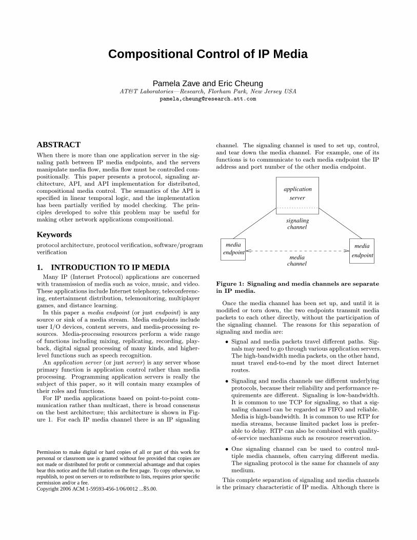
channel. The signaling channel is used to set up, control,and tear down the media channel. For example, one of itsfunctions is to communicate to each media endpoint the IPaddress and port number of the other media endpoint.
serverapplication
mediaendpoint
channelmedia endpoint
media
channelsignaling
Figure 1: Signaling and media channels are separatein IP media.
Once the media channel has been set up, and until it ismodified or torn down, the two endpoints transmit mediapackets to each other directly, without the participation ofthe signaling channel. The reasons for this separation ofsignaling and media are:
† Signal and media packets travel different paths. Sig-nals may need to go through various application servers.The high-bandwidth media packets, on the other hand,must travel end-to-end by the most direct Internetroutes.
† Signaling and media channels use different underlyingprotocols, because their reliability and performance re-quirements are different. Signaling is low-bandwidth.It is common to use TCP for signaling, so that a sig-naling channel can be regarded as FIFO and reliable.Media is high-bandwidth. It is common to use RTP formedia streams, because limited packet loss is prefer-able to delay. RTP can also be combined with quality-of-service mechanisms such as resource reservation.
† One signaling channel can be used to control mul-tiple media channels, often carrying different media.The signaling protocol is the same for channels of anymedium.
This complete separation of signaling and media channelsis the primary characteristic of IP media. Although there is
also signaling/media separation in circuit-switched telecom-munications, the separation is not as complete. In circuit-switched networks, signaling and media may have differenttransport protocols, but signals for a media channel travelthe same path, through the same switches, as the mediapackets.In general, to set up media flow in each direction between
two endpoints,1 the sender in that direction must know thereceiver’s IP address and port number. Both endpoints mustknow the codec (coder-decoder) that will be employed for themedia stream in that direction. A codec is a data format fora medium. For example, G.726 is a lower-fidelity and lower-bandwidth codec for voice, while G.711 is a higher-fidelityand higher-bandwidth codec for voice. G.711 is approxi-mately equivalent in fidelity to circuit-switched telephony.
2. THE PROBLEM OF COMPOSITIONALMEDIA CONTROL
2.1 What is compositional media control?Among other functions, application servers must control
the media channels whose signaling channels they partic-ipate in. The most common media-control functions areopening, closing, switching, and holding (temporarily inter-rupting) media channels.Such functions are very common. In telecommunication
applications, for example, they serve more purposes thanjust the obvious ones of switching or conferencing users.Any feature that employs the voice channel for signaling (bymeans of announcements, prompts, touch-tone recognition,speech recognition, etc.) must switch user voice channels toand from voice-processing resources.The problem of compositional control arises when the
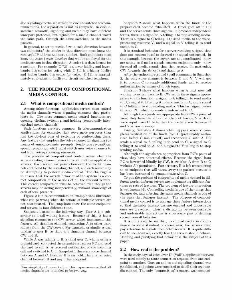
same signaling channel passes through multiple applicationservers. Each server has jurisdiction over the media chan-nels controlled by the signaling channel, and each server maybe attempting to perform media control. The challenge isto ensure that the overall behavior of the system is a cor-rect composition of the actions of all the relevant servers.This correct composition must be achieved even though theservers may be acting independently, without knowledge ofeach others’ presence.Figure 2 is a telecommunication example that illustrates
what can go wrong when the actions of multiple servers arenot coordinated. The snapshots show the same endpointsand servers at four different times.Snapshot 1 arose in the following way. User A is a sub-
scriber to a call-waiting feature. Because of this, A has asignaling channel to the CW server, which implements thisfeature. All signaling channels connecting A to other usersradiate from the CW server. For example, originally A wastalking to user B, so there is a signaling channel betweenCW and B.While A was talking to B, a third user C, who is using a
prepaid card, contacted the prepaid-card server PC and usedthe card to call A. A received notification of the incomingcall and switched to C. In Snapshot 1 there is a voice channelbetween A and C. Because B is on hold, there is no voicechannel between B and any other endpoint.
1For simplicity of presentation, this paper assumes that allmedia channels are intended to be two-way.
Snapshot 2 shows what happens when the funds of theprepaid card become exhausted. A timer goes off in PCand the server sends three signals. In protocol-independentterms, there is a signal to A telling it to stop sending media.There is a signal to C telling it to send media to the voice-processing resource V, and a signal to V telling it to sendmedia to C.It is standard behavior for a server receiving a signal that
does not concern itself to forward the signal untouched. Inthis example, because the servers are not coordinated—theyare acting as if media signals concern endpoints only—theyforward all media signals that they receive. In particular,CW forwards the do not send signal to A.After the endpoints respond to all commands in Snapshot
2, the only voice channel is between C and V. V will useit to prompt C to supply additional funds, and to receiveauthorization by means of touch tones.Snapshot 3 shows what happens when A next uses call
waiting to switch back to B. CW sends three signals appro-priate to this function: a signal to A telling it to send mediato B, a signal to B telling it to send media to A, and a signalto C telling it to stop sending media. This last signal passesthrough PC, which forwards it untouched to C.Although the signals are appropriate from CW’s point of
view, they have the abnormal effect of leaving V withoutvoice input from C. Note that the media arrow between Cand V is now one-way.Finally, Snapshot 4 shows what happens when V com-
pletes verification of the funds from C (presumably autho-rized before C was cut off) and reconnects C with A. PCsends a signal to A telling it to send to C, a signal to Ctelling it to send to A, and a signal to V telling it to stopsending media.Although the signals are appropriate from PC’s point of
view, they have abnormal effects. Because the signal fromPC is forwarded blindly by CW, it switches A from B to Cwithout A’s permission. Furthermore, B is left transmittingto an endpoint that will throw away the packets because ithas been instructed to communicate with C.To put the problem of compositional media control in dif-
ferent words, different servers are implementing different fea-tures or sets of features. The problem of feature interactionis well known [4]. Controlling media is one of the things thatfeatures do, and affecting the same media channels is one ofthe ways that features interact. The purpose of composi-tional media control is to manage these feature interactionsso that desirable interactions are enabled and undesirableones are prevented. Thus, a distinction between desirableand undesirable interactions is a necessary part of definingcorrect overall behavior.It is quite easy to see that, to control media in confor-
mance to some standard of correctness, the servers mustpay attention to signals from other servers. It is quite diffi-cult to see, however, exactly how the servers should behave.Defining and justifying that behavior is the subject of thispaper.
2.2 How real is the problem?In the early days of voice-over-IP (VoIP), application servers
were used mainly to route connection requests from one end-point to another. Once an end-to-end signaling channel wasestablished, endpoints were expected to do all their own me-dia control. The only “composition” required was composi-
A 43
2
C
B
VC
BA
C V
AB
V
1 A
C V
B
CW
to A
to Vsend
to Csend
to B send
do notsend
to A
send
send
do not
PC
CW
PC
PCPC
CWsend
to C
send
do not
send
CW
Figure 2: An example of erroneous media control in telecommunications. A, B, C, and V are endpoints.CW and PC are servers implementing call-waiting and prepaid-card features, respectively. Solid lines aresignaling channels, dashed lines are media channels, and dotted lines are signals sent on signaling channels.
tion of the intentions of the communicating endpoints. Thiscomposition was achieved directly by the signaling protocol,as all protocols are designed to make agreements betweenthe endpoints using them.IP media is becoming more widely used, and there are
increasingly many reasons why the early viewpoint is notsufficient. First we consider reasons why it might be neces-sary or desirable to have media-control features that are notimplemented in endpoints:
† It might not always be possible to add arbitrary newsoftware to endpoints. Consumer devices are diverse,and small consumer devices do not usually have up-datable software.
† Features requiring media resources such as conferencebridges or speech processors cannot be implementedin endpoints if the endpoints do not incorporate suchresources or have access to them.
† Features that make personal data such as voice record-ings reliably accessible to customers from all locationsand endpoints cannot be implemented in endpoints un-less the endpoints are reliably accessible at all times.
† A multimedia feature integrating the media capabili-
ties of two or more devices is not easily implementedon one device.
† Functions such as providing security or billing for us-age cannot be implemented in user endpoints becausethe endpoints do not reside in a trusted administrativedomain.
† Service providers may wish to offer value-added com-munication services. They can only do this by im-plementing them in network servers and arranging forconsumer access to the servers.
If there are media-control features in endpoints, even oneapplication server in the signaling path may be enough tocause unanticipated interactions between media-control fea-tures.Once we understand why servers might perform media
control, it is easy to see why there might be multiple in-dependent application servers in a signaling path. In thecomposition example, CW is associated with user A, PC isassociated with user C, and the two have nothing to do witheach other except that C decided to call A. The two serversare in different administrative domains, and neither has anyway to know that the other is present in the signaling path.
BB
V V
1 A
C
A
BA
C
PC
C
CW
PC
CW
VV
PCPC
2
C
CW
BA 43
CW
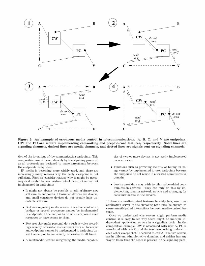
Figure 3: Correct media control using the API, in contrast to Figure 2.
Another important reason for multiple independent appli-cation servers in a signaling path is the requirements of largeservice providers, who operate clusters of servers. Theseclusters typically include servers developed independentlyby different vendors. Many of these servers have special-ized purposes such as PBX functionality or voice mail. TheIP Multimedia Subsystem (IMS) architecture [1], which isan emerging industry standard, recognizes the necessity toroute a particular signaling channel through multiple serverswithin the same service provider’s configuration.The final reason for studying multiple independent ap-
plication servers in a signaling path concerns software en-gineering. The media application with the longest historyis telecommunications. It has long been recognized by itspractitioners that their software is continually changing be-cause of the addition of features, and that their software isvery difficult to develop because of feature interactions [4].One successful approach to managing feature interactions
is the Distributed Feature Composition (DFC) architecture[3, 7], in which features behave as independent modules insignaling paths. In other words, a feature in the DFC archi-tecture plays the same role as an independent server, eventhough it is packaged inside an application server acting asa platform for many features. By making feature modulesas independent as possible, the architecture allows each fea-ture to be simple and comprehensible, and makes it easy to
add or change features.As an example of both the second and third reasons for
multiple servers in a path, a typical call to or from a user ofa commercial VoIP service [2] goes through two applicationservers owned by the service provider. One is supplied byan equipment vendor, and supports basic, PBX-like features.The other application server provides up to 15 advanced fea-tures, and is programmed using the DFC architecture. Anordinary call with only one party subscribing to the servicecould easily have ten DFC feature modules in its signalingpath.It is important to note that the modularity argument ap-
plies to features regardless of where they are implemented.Even if all media-control features reside in endpoints, if thefeatures are complex enough, it may be better to programthem as if they were independent servers.
3. OVERVIEW OF A SOLUTIONThis paper presents a comprehensive solution to the prob-
lem of compositional control of IP media. In this section wedescribe the solution at the highest possible level; subse-quent sections provide the details.This paper does not discuss how the endpoints, servers,
and signaling channels of a media application are configuredand assembled, nor how they evolve over time. Everything isdescribed within the context of a fixed “current” graph such
as the one found in Figure 2. Configuration and assemblyare performed in varying ways by IMS, DFC, and the SessionInitiation Protocol (SIP) for multimedia applications [10].At the highest level, the solution is exemplified by Fig-
ure 3. In this figure, the CW and PC servers are pro-grammed using an application programming interface (API)for media control.When a server program wants media flow between two
endpoints, it puts the two signaling channels that extendfrom the server to those endpoints under control of a flowlinkobject, depicted by a dotted line in the figure. When a serverprogram wants to interrupt media flow to an endpoint, itputs the signaling channel to that endpoint under controlof a holdlink object, depicted by a black dot in the figure.The API also offers an openlink for opening media channelsand a closelink for closing them, but these objects are notemployed in the CW/PC example.The signaling protocol and the implementation of the link
objects are designed to achieve the goals of the servers inwhich they reside, subject to the goals of other servers andthe rule for coordinating them. Roughly speaking, the coor-dination rule is that proximity confers priority. This meansthat the closer a server is to an endpoint, the higher priorityit has in controlling media flow to and from that endpoint.Figure 3 has the same four snapshots as in Figure 2;
dashed lines show the media flow that results from eachlink state in the servers. In this example, the semantics ofthe API and the coordinating rule can be characterized asfollows: there is media flow between two endpoints if andonly if there is an unbroken chain of signaling channels andflowlinks between them.To relate this behavior to proximity, consider the CW
server. In every snapshot, A is media-connected to B if theCW server mandates it, and may be media-connected to Cif the CW server allows it. Because the CW server is closestto A, it has priority over PC in controlling A. Only if CWhas A linked to C do the actions of PC have an effect on A.Then A may actually be media-connected to C (Snapshot 1)or be silent (Snapshot 2), depending on the actions of PC.The rule of proximity confers priority has been used to
govern media-control feature interactions in many applica-tions built using the IP-based implementation of DFC [3].It is convenient, intuitive, and sufficient for a wide range ofapplications, provided that there is enough control of theconfiguration graph in which proximity is measured.The new contributions reported in this paper include the
API, a signaling protocol for media control, a formal spec-ification of correctness in terms of the API and protocol,an implementation of the link objects, and a partial veri-fication that the implementation satisfies the specification.These are described in subsequent sections, with related andfuture work at the end of the paper.
4. SIGNALING PROTOCOL
4.1 Signaling architectureWe use the word box for any independent module in a sig-
naling path, whether it is a whole application server or aDFC-like feature module within an application server. Asshown in Figure 4, a graph representing a current configu-ration consists of boxes and signaling channels. In Figures1 through 4, all the boxes are peers.In general, a signaling channel can control more than one
media endpoint
box or
endpoint
box
flowlink
actual or potential media channel
tunnel
signalingchannel
mediabox or
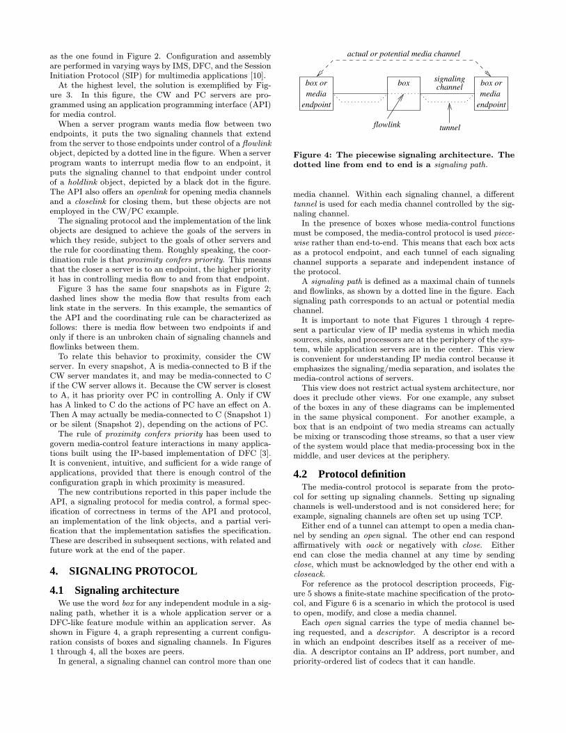
Figure 4: The piecewise signaling architecture. Thedotted line from end to end is a signaling path.
media channel. Within each signaling channel, a differenttunnel is used for each media channel controlled by the sig-naling channel.In the presence of boxes whose media-control functions
must be composed, the media-control protocol is used piece-wise rather than end-to-end. This means that each box actsas a protocol endpoint, and each tunnel of each signalingchannel supports a separate and independent instance ofthe protocol.A signaling path is defined as a maximal chain of tunnels
and flowlinks, as shown by a dotted line in the figure. Eachsignaling path corresponds to an actual or potential mediachannel.It is important to note that Figures 1 through 4 repre-
sent a particular view of IP media systems in which mediasources, sinks, and processors are at the periphery of the sys-tem, while application servers are in the center. This viewis convenient for understanding IP media control because itemphasizes the signaling/media separation, and isolates themedia-control actions of servers.This view does not restrict actual system architecture, nor
does it preclude other views. For one example, any subsetof the boxes in any of these diagrams can be implementedin the same physical component. For another example, abox that is an endpoint of two media streams can actuallybe mixing or transcoding those streams, so that a user viewof the system would place that media-processing box in themiddle, and user devices at the periphery.
4.2 Protocol definitionThe media-control protocol is separate from the proto-
col for setting up signaling channels. Setting up signalingchannels is well-understood and is not considered here; forexample, signaling channels are often set up using TCP.Either end of a tunnel can attempt to open a media chan-
nel by sending an open signal. The other end can respondaffirmatively with oack or negatively with close. Eitherend can close the media channel at any time by sendingclose, which must be acknowledged by the other end with acloseack.For reference as the protocol description proceeds, Fig-
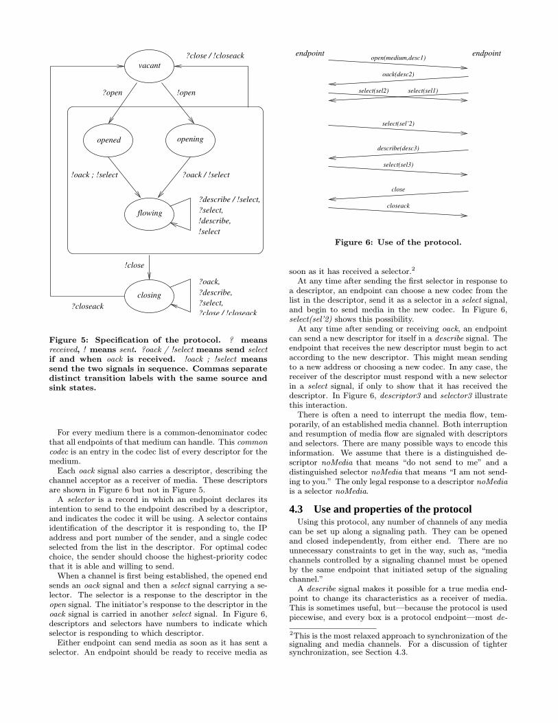
ure 5 shows a finite-state machine specification of the proto-col, and Figure 6 is a scenario in which the protocol is usedto open, modify, and close a media channel.Each open signal carries the type of media channel be-
ing requested, and a descriptor. A descriptor is a recordin which an endpoint describes itself as a receiver of me-dia. A descriptor contains an IP address, port number, andpriority-ordered list of codecs that it can handle.
?describe,?oack,
opened opening
!select
flowing
?oack / !select!oack ; !select
?select,
vacant
closing
?close / !closeack
!open
?close / !closeack?closeack
!close
?open
!describe,?select,?describe / !select,
Figure 5: Specification of the protocol. ? meansreceived, ! means sent. ?oack / !select means send selectif and when oack is received. !oack ; !select meanssend the two signals in sequence. Commas separatedistinct transition labels with the same source andsink states.
For every medium there is a common-denominator codecthat all endpoints of that medium can handle. This commoncodec is an entry in the codec list of every descriptor for themedium.Each oack signal also carries a descriptor, describing the
channel acceptor as a receiver of media. These descriptorsare shown in Figure 6 but not in Figure 5.A selector is a record in which an endpoint declares its
intention to send to the endpoint described by a descriptor,and indicates the codec it will be using. A selector containsidentification of the descriptor it is responding to, the IPaddress and port number of the sender, and a single codecselected from the list in the descriptor. For optimal codecchoice, the sender should choose the highest-priority codecthat it is able and willing to send.When a channel is first being established, the opened end
sends an oack signal and then a select signal carrying a se-lector. The selector is a response to the descriptor in theopen signal. The initiator’s response to the descriptor in theoack signal is carried in another select signal. In Figure 6,descriptors and selectors have numbers to indicate whichselector is responding to which descriptor.Either endpoint can send media as soon as it has sent a
selector. An endpoint should be ready to receive media as
select(sel’2)
select(sel2)
oack(desc2)
open(medium,desc1)
describe(desc3)
select(sel1)
closeack
close
select(sel3)
endpointendpoint
Figure 6: Use of the protocol.
soon as it has received a selector.2
At any time after sending the first selector in response toa descriptor, an endpoint can choose a new codec from thelist in the descriptor, send it as a selector in a select signal,and begin to send media in the new codec. In Figure 6,select(sel’2) shows this possibility.At any time after sending or receiving oack, an endpoint
can send a new descriptor for itself in a describe signal. Theendpoint that receives the new descriptor must begin to actaccording to the new descriptor. This might mean sendingto a new address or choosing a new codec. In any case, thereceiver of the descriptor must respond with a new selectorin a select signal, if only to show that it has received thedescriptor. In Figure 6, descriptor3 and selector3 illustratethis interaction.There is often a need to interrupt the media flow, tem-
porarily, of an established media channel. Both interruptionand resumption of media flow are signaled with descriptorsand selectors. There are many possible ways to encode thisinformation. We assume that there is a distinguished de-scriptor noMedia that means “do not send to me” and adistinguished selector noMedia that means “I am not send-ing to you.” The only legal response to a descriptor noMediais a selector noMedia.
4.3 Use and properties of the protocolUsing this protocol, any number of channels of any media
can be set up along a signaling path. They can be openedand closed independently, from either end. There are nounnecessary constraints to get in the way, such as, “mediachannels controlled by a signaling channel must be openedby the same endpoint that initiated setup of the signalingchannel.”A describe signal makes it possible for a true media end-
point to change its characteristics as a receiver of media.This is sometimes useful, but—because the protocol is usedpiecewise, and every box is a protocol endpoint—most de-
2This is the most relaxed approach to synchronization of thesignaling and media channels. For a discussion of tightersynchronization, see Section 4.3.
scribe signals are sent by application servers.For example, consider the transition from Snapshot 1 to
Snapshot 2 in Figure 3. To implement this transition, PCsends a describe signal with descriptor noMedia to A, a de-scribe signal with the descriptor of C to V, and a describesignal with the descriptor of V to C. (PC has these descrip-tors available because it has recorded them as they passedthrough in previous signals.) The answering select signalfrom A is absorbed by PC, and the answering select signalsfrom C and V are sent to each other. These signals willcause the actual media paths to change as indicated in thefigure.To make media control as easy as possible, describe signals
(and their answering selects) going in opposite directions inthe same tunnel do not constrain each other. This meansthat changes initiated in both directions can proceed con-currently. There is no need to introduce the complexity andoverhead of serializing them.Another simplifying design decison is that the protocol
has no enforced pairing of describe/select signals relevant tomedia transmission in one direction. A describe can be sentat any time, even if no select has been received in responseto the last describe. A select can be sent at any time, even ifno describe has been received since the last select was sent.This makes box state simpler and eliminates unnecessaryconstraints.In addition to being designed to facilitate composition,
our protocol is also designed to yield an optimal choice ofcodec. In each direction of a media channel, the sender issending the best codec it is currently willing to send, fromthe viewpoint of the receiver. The protocol does not forcethe two directions of a media channel to use the same codec;such a restriction would have no intrinsic value, and wouldsometimes make the code choice suboptimal.A selector identifies a single codec because many media
endpoints must allocate resources to whatever codec theyare receiving. When they receive a new selector with a newcodec, this triggers them to reconfigure themselves. Mediasources may wish to send different codecs even within thesame media episode. For example, a resource that playsrecorded speech may have speech files that were stored inseveral different codecs.To make absolutely sure that no media is lost, even if me-
dia packets travel through the network faster than signals,an endpoint must begin “listening” for media in accordancewith a descriptor as soon as it has sent the descriptor, andmust be able to accept packets in any allowed codec at anytime. This is possible because codecs are self-describing. Itis easier, however, for an endpoint to wait for select signalsand risk the loss of a few packets that arrive before theircorresponding selectors.
5. APPLICATION PROGRAMMING INTER-FACE (API)
5.1 SlotsA box is an endpoint of some set of signaling channels.
Within each signaling channel, the box is a protocol end-point of some set of tunnels. The programmer must havesome way to identify these tunnel endpoints so that theycan be manipulated separately.The software abstraction that serves this purpose in the
API is the slot. A slot is a software object that correspondsto an actual or potential tunnel endpoint, and is associatedwith the role that the actual or potential tunnel endpointplays within the box.In this paper we do not go into the details of how Slot ob-
jects and tunnel endpoints are associated, as that is some-what application-dependent. The important point is thattunnel endpoints are dynamic and slots are static. A slotcan be vacant, meaning that no tunnel endpoint is filling it.Or it can be filled by a tunnel endpoint. During its lifetimea slot can be repeatedly vacant and filled again, as the corre-sponding media channel is repeatedly lost and then replacedor restored.The Java signature of a Slot object is:
public class Slot {
private SigChan sigChan;
private int state, tunnel;private Descriptor descriptor;
...
}
where the sigChan and tunnel identify the tunnel endpointthat is currently occupying the slot, if the slot is filled.The five Slot states are vacant, opened, opening, flowing,
and closing, which are the same as the protocol states inFigure 5. The state of a slot is its state as a tunnel endpoint.The descriptor of a slot is the most recent descriptor re-
ceived from the other endpoint in an open, oack, or describesignal.
5.2 Programming with linksA Link is an object that controls one or two slots. As
mentioned in Section 3, there are four link types, each witha different goal. These goals are discussed in detail in Sec-tion 5.3.Every slot must be under the control of a Link object at
all times. The Link object sees every signal received by thebox through its slots, and mandates the sending of everysignal sent by the box through its slots.Although a slot must be under control of a link at all
times, it does not live its entire life within one link. Rather,the program moves slots from link to link to achieve itscurrent goals. A move may take a slot from one type of linkto another, or it may take it from a flowlink with one slotpartner to a flowlink with a different slot partner.When a Link object is created, it receives its slot or slots
as arguments. Because slots are moved from link to link, aslot can enter a link in any state. Thus the first action ofa link is to query each slot to find out what state it is in.Then, having completed this initialization, the Link objectproceeds to control its slot or slots until its slots are movedelsewhere and this Link object becomes garbage.Slots are a powerful programming abstraction because
they represent the roles of virtual segments of media chan-nels within boxes, regardless of whether the media chan-nels exist at the moment or not. This is important becausewhether a media channel exists at a particular moment de-pends primarily on the media endpoints, and a box programhas limited control over it.In the same way, links are a powerful programming ab-
straction because they represent goals for slots regardlessof the states of the slots. This is important because manystate changes within media servers are caused by timeouts,

user commands, or other stimuli that are independent ofslot states. With links, a program can simply react to suchstimuli with a re-assignment of slots to links. The link imple-mentation automatically takes care of the actual slot states,and of managing them so that the link goal is achieved.Needless to say, some state changes within application
servers do depend on slot states. The API provides a wayfor an application program to detect slot states, so that statechanges can also act as stimuli.
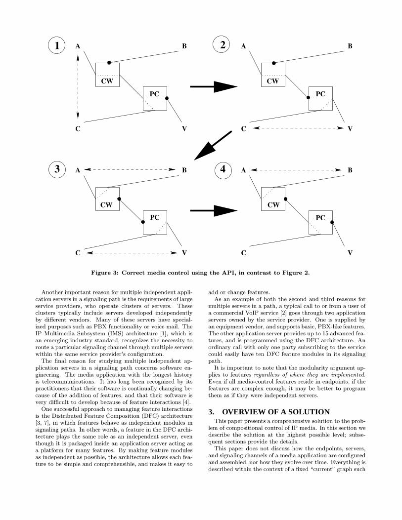
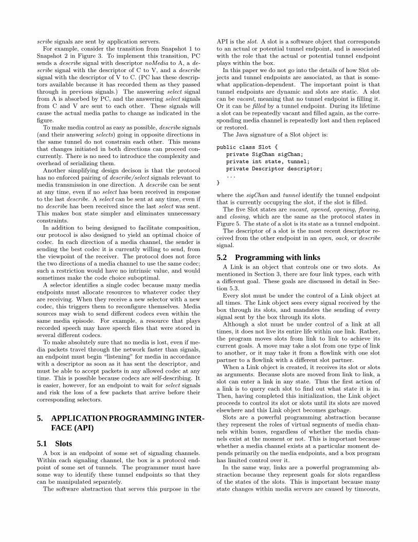
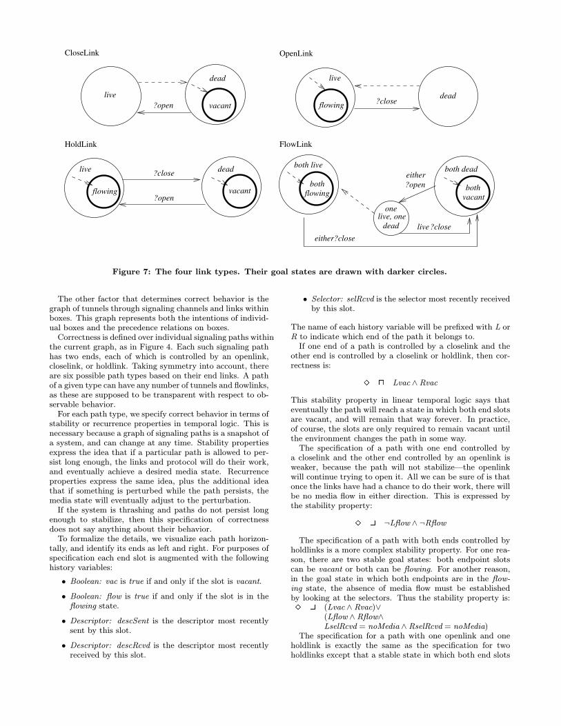
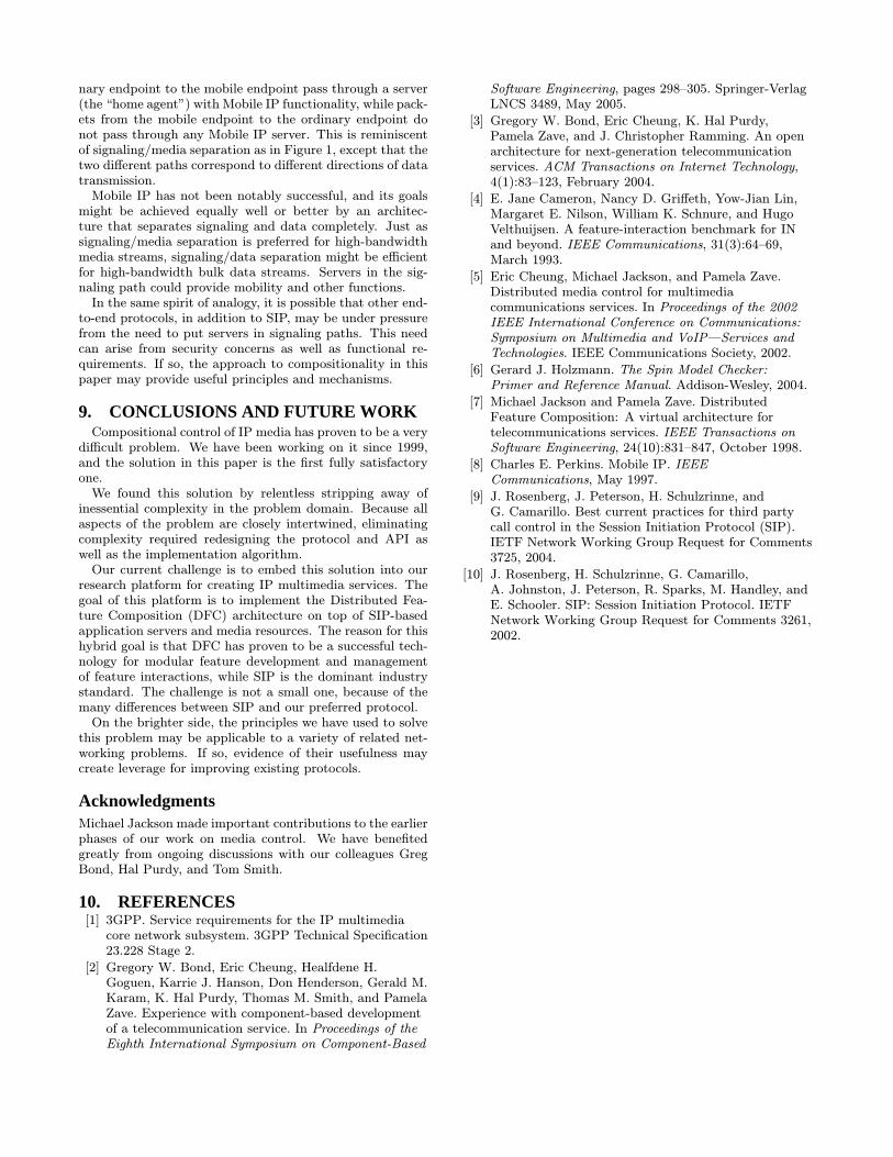
5.3 Link goalsFigure 7 has finite-state machines specifying the goals of
the four link types. The state of a Link object, as shown inFigure 7, is derived from the state of its slot or slots. Thestate label dead means closing or vacant, and the state labellive means opening, opened, or flowing. The figure showsonly received signals that change the states of the machines,i.e., it does not show signals sent or self-transitions. Dashedarrows show the work that each link does to reach its goal.Beginning with the simplest type, the goal of a CloseLink
is to make its slot vacant. When a filled slot enters thecontrol of the link, the link immediately forces the slot toa closing state by sending a close signal. Once the slot hasreceived a closeack signal, the link has achieved its goal. Ifafterwards the slot receives a fresh open signal, the link againforces it to a closing state.The goal of an OpenLink is to get its slot to the flowing
state. When a vacant slot enters the control of an OpenLink,the link immediately forces the slot to an opening state bysending an open signal. If the open signal is rejected or thechannel is subsequently closed, the OpenLink will try again.Usually media channels are opened by media endpoints,
but occasionally they must be opened by boxes, creating theneed for OpenLinks. Consider, for example, a box programfor a Click-to-Dial feature. When a user of a Web site clicksa Click-to-Dial number, the feature first creates a signalingchannel to the telephone of the clicker, and opens a voicechannel to it. This is necessary because the standard prac-tice in telephony is to open a voice channel to a telephonebefore starting its ringing. If and when the user answers,the box creates a signaling channel to the clicked number,and does its best to create media flow between the two tele-phones. This Java code might be part of the box program:
// initialization
Slot slot1, slot2; Link open, flow;
// on activation
slot1 = new Slot(toClicker);open = new OpenLink(voice,slot1);
The argument to a Slot constructor is the signaling channel,which in this case goes toward the clicker. The argumentto an OpenLink constructor (in addition to its slot) is themedium, because the Link must send an open signal, whichrequires it.The OpenLink puts a noMedia descriptor into the open
that it sends. The media channel must be set up so theclicker’s telephone will ring, but there is no other mediaendpoint for the telephone to send media to. If and whenthe other endpoint is present, this box will send its realvoice descriptor to the clicker’s telephone in a describe signal.(This is accomplished by a FlowLink, as described below.)The API allows the box program to sense the state of a
slot at any time. If the OpenLink fails because the open is
rejected, then the program can detect this and abort. It ismore likely, however, that success and failure will be signaledat the level of the signaling channel as a whole. If the entiresignaling channel is torn down as a result of failure, then allits tunnels and slots will disappear.If and when the call to the clicker is answered, the box
program creates a signaling channel toward the clicked num-ber. To complete its job, the box must open a voice channeltoward the clicked number, and ensure that both endpointshave the right descriptors and selectors. It can do all ofthe media control simply by putting the two voice slots in aFlowLink, as follows:
// when the clicker answers
slot2 = new Slot(toClicked);
flow = new FlowLink(slot1,slot2);
The goal of a FlowLink is to make a media connection be-tween its two slots.The FlowLink is by far the most complex link type, be-
cause it has two slots that can enter the link in any states,and the link must match both their states and descriptors.Most importantly, if two live states enter it, it will work to-ward making both slots flowing with correct descriptors andselectors. This may require sending each slot the most recentdescriptor from the other slot, as described in Section 4.3.If both slots are live and it receives a close from one of
them, it will work to make both slots vacant. If two deadstates enter it, it will work toward making both slots vacant.If both slots are dead and it receives an open from one ofthem, it will work to make both slots flowing with correctdescriptors and selectors.If one slot is live and one slot is dead, the FlowLink works
to make both slots flowing. This behavior makes sense ifone live, one dead is an intermediate state. For example,after receiving an open signal when both slots were dead,the FlowLink may have one slot opened (live) and one slotclosing (dead). In this state, the link is blocked. As soon asit receives closeack from the dead slot, it can send an openthrough that slot, and both slots will be live.The behavior also makes sense if one live, one dead is an
initial state, on the grounds that the bias of media controlshould be toward creating media flow rather than destroyingit. For more about FlowLinks, see Section 6.The final link type is a HoldLink, which puts a slot “on
hold.” If the slot is dead, the link tries to make it vacant.If the slot is live, the link tries to make it flowing, but withno actual media flow. This is done by sending it a noMediadescriptor.These four link types are sufficient for all applications
not based on multicast. They might seem to be insuffi-cient because they cannot be used to construct multi-pointmedia paths. Without multicast, however, multi-point me-dia connections are always implemented within a “bridge”or “mixer” resource. All the participating media endpointshave point-to-point media channels to this resource.
5.4 Specification of correctnessTo specify correctness, we assume that media endpoints
are also programmed using slots and links. The goals ofmedia endpoints are indicated by whether their slots arecontrolled by openlinks, closelinks, or holdlinks. These goalsare one of the factors that combine to determine correctbehavior.
bothflowing vacant
both?openeither
either?close?close
?close
?open
live
vacantflowing
both deadboth live
live
CloseLink
vacant
OpenLink
dead?closeflowing
live
?open
onelive, one
dead
HoldLink FlowLink
dead
live
dead
Figure 7: The four link types. Their goal states are drawn with darker circles.
The other factor that determines correct behavior is thegraph of tunnels through signaling channels and links withinboxes. This graph represents both the intentions of individ-ual boxes and the precedence relations on boxes.Correctness is defined over individual signaling paths within
the current graph, as in Figure 4. Each such signaling pathhas two ends, each of which is controlled by an openlink,closelink, or holdlink. Taking symmetry into account, thereare six possible path types based on their end links. A pathof a given type can have any number of tunnels and flowlinks,as these are supposed to be transparent with respect to ob-servable behavior.For each path type, we specify correct behavior in terms of
stability or recurrence properties in temporal logic. This isnecessary because a graph of signaling paths is a snapshot ofa system, and can change at any time. Stability propertiesexpress the idea that if a particular path is allowed to per-sist long enough, the links and protocol will do their work,and eventually achieve a desired media state. Recurrenceproperties express the same idea, plus the additional ideathat if something is perturbed while the path persists, themedia state will eventually adjust to the perturbation.If the system is thrashing and paths do not persist long
enough to stabilize, then this specification of correctnessdoes not say anything about their behavior.To formalize the details, we visualize each path horizon-
tally, and identify its ends as left and right. For purposes ofspecification each end slot is augmented with the followinghistory variables:
† Boolean: vac is true if and only if the slot is vacant.† Boolean: flow is true if and only if the slot is in theflowing state.
† Descriptor: descSent is the descriptor most recentlysent by this slot.
† Descriptor: descRcvd is the descriptor most recentlyreceived by this slot.
† Selector: selRcvd is the selector most recently receivedby this slot.
The name of each history variable will be prefixed with L orR to indicate which end of the path it belongs to.If one end of a path is controlled by a closelink and the
other end is controlled by a closelink or holdlink, then cor-rectness is:
3 2 Lvac ^ RvacThis stability property in linear temporal logic says thateventually the path will reach a state in which both end slotsare vacant, and will remain that way forever. In practice,of course, the slots are only required to remain vacant untilthe environment changes the path in some way.The specification of a path with one end controlled by
a closelink and the other end controlled by an openlink isweaker, because the path will not stabilize—the openlinkwill continue trying to open it. All we can be sure of is thatonce the links have had a chance to do their work, there willbe no media flow in either direction. This is expressed bythe stability property:
3 2 :Lflow ^ :RflowThe specification of a path with both ends controlled by
holdlinks is a more complex stability property. For one rea-son, there are two stable goal states: both endpoint slotscan be vacant or both can be flowing. For another reason,in the goal state in which both endpoints are in the flow-ing state, the absence of media flow must be establishedby looking at the selectors. Thus the stability property is:3 2 (Lvac ^ Rvac)_
(Lflow ^ Rflow^LselRcvd = noMedia ^ RselRcvd = noMedia)
The specification for a path with one openlink and oneholdlink is exactly the same as the specification for twoholdlinks except that a stable state in which both end slots
are vacant is not acceptable:3 2 Lflow ^ Rflow^
LselRcvd = noMedia^RselRcvd = noMedia
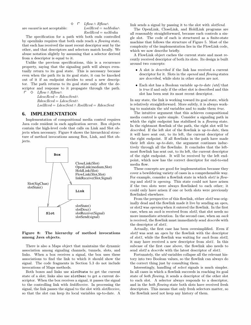
The specification for a path with both ends controlledby openlinks requires that both ends reach a flowing state,that each has received the most recent descriptor sent by theother, and that descriptors and selectors match locally. Weabuse notation slightly by assuming that a selector derivedfrom a descriptor is equal to it.Unlike the previous specifications, this is a recurrence
property, saying that the signaling path will always even-tually return to its goal state. This is necessary becauseeven when the path its in its goal state, it can be knockedout of it if an endpoint decides to send a new descrip-tor. The path returns to its goal state only after the de-scriptor and response to it propagate through the path.2 3 Lflow ^ Rflow^
LdescRcvd = RdescSent^RdescRcvd = LdescSent^LselRcvd = LdescSent ^ RselRcvd = RdescSent
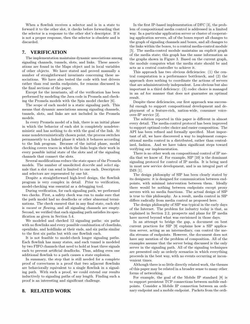
6. IMPLEMENTATIONImplementation of compositional media control requires
Java code resident in each application server. Box objectscontain the high-level code that calls on Link and Slot ob-jects when necessary. Figure 8 shows the hierarchical struc-ture of method invocations among Box, Link, and Slot ob-jects.
slotDesc()slotState()
Link
linkReceive(Slot,Signal)
slotReceive(Signal)
slotState()Slot(SigChan)
SlotslotSend(signal)
FlowLink(Slot,Slot)HoldLink(Slot)OpenLink(medium,Slot)CloseLink(Slot)
Box
Figure 8: The hierarchy of method invocationsamong Java objects.
There is also a Maps object that maintains the dynamicassociation among signaling channels, tunnels, slots, andlinks. When a box receives a signal, the box uses theseassociations to find the link to which it should show thesignal. The code fragments in Section 5.3 do not includeinvocations of Maps methods.Both boxes and links use slotState to get the current
state of a slot; links also use slotDesc to get a current de-scriptor. When the box receives a signal, it passes the signalto the controlling link with linkReceive. In processing thesignal, the link passes the signal to the slot with slotReceive,so that the slot can keep its local variables up-to-date. A
link sends a signal by passing it to the slot with slotSend.The OpenLink, CloseLink, and HoldLink programs are
all reasonably straightforward, because each controls a sin-gle slot. The code of each is structured as a finite-statemachine that follows the structure of Figure 5. Most of thecomplexity of the implementation lies in the FlowLink code,which we now describe briefly.A FlowLink object caches the current state and most re-
cently received descriptor of both its slots. Its design is builtaround two concepts:
† A slot is described if the link has received a currentdescriptor for it. Slots in the opened and flowing statesare described, while slots in other states are not.
† Each slot has a Boolean variable up-to-date (utd) thatis true if and only if the other slot is described and thisslot has been sent its most recent descriptor.
In any state, the link is working toward its goal state, whichis relatively straightforward. More subtly, it is always work-ing to maintain the utd variables and to make them true.The intuitive argument that this achieves compositional
media control is quite simple. Consider a signaling path inwhich the right endpoint has stabilized in a flowing state.In the rightmost flowlink of the path, the right slot will bedescribed. If the left slot of the flowlink is up-to-date, thenit will have sent out, to its left, the current descriptor ofthe right endpoint. If all flowlinks in the path have madetheir left slots up-to-date, the argument continues induc-tively through all the flowlinks. It concludes that the left-most flowlink has sent out, to its left, the current descriptorof the right endpoint. It will be received by the left end-point, which now has the correct descriptor for end-to-endmedia flow.These concepts are good for implementation because they
cover a bewildering variety of cases in a comprehensible way.For example, consider a flowlink state in which slot1 is flow-ing and slot2 is opening. This state could not have arisenif the two slots were always flowlinked to each other; itcould only have arisen if one or both slots were previouslyflowlinked elsewhere.From the perspective of this flowlink, either slot2 was orig-
inally dead and the flowlink made it live by sending an open,or slot2 was opening when it entered the flowlink. In the firstcase, when an oack is received from slot2, that slot needs nomore immediate attention. In the second case, when an oackis received, the flowlink must immediately send describe withthe descriptor of slot1.Actually, the first case has been oversimplified. Even if
slot2 was sent an open by the flowlink with the descriptorof slot1, while the flowlink was waiting for oack from slot2,it may have received a new descriptor from slot1. In thissubcase of the first case above, the flowlink also needs tosend slot2 a describe with the latest descriptor of slot1.Fortunately, the utd variables collapse all the relevant his-
tory into two Boolean values, so the flowlink can always dothe correct thing just by consulting them.Interestingly, handling of select signals is much simpler.
In all cases in which a flowlink succeeds in reaching its goalstate of both flowing, it sends a descriptor of the other slotto each slot. A selector always responds to a descriptor,and in the both flowing state both slots have received freshdescriptors. This means that only fresh selectors matter, sothe flowlink need not keep any history of them.
When a flowlink receives a selector and is in a state toforward it to the other slot, it checks before forwarding thatthe selector is a response to the other slot’s descriptor. If itis not a proper response, then the selector is obsolete and isdiscarded.
7. VERIFICATIONThe implementation maintains dynamic associations among
signaling channels, tunnels, slots, and links. These associ-ations are found in the Maps object and in local variablesof other objects. We have stated and proved manually anumber of straightforward invariants concerning these as-sociations. We have also tested the code with test driversrather than real media endpoints, for reasons discussed inthe final sections of the paper.Except for the invariants, all of the verification has been
performed by modeling the Java code in Promela and check-ing the Promela models with the Spin model checker [6].The scope of each model is a static signaling path. This
means that dynamic associations among signaling channels,tunnels, slots, and links are not included in the Promelamodels.In every Promela model of a link, there is an initial phase
in which the behavior of each slot is completely nondeter-ministic and has nothing to do with the goal of the link. Atsome nondeterministically chosen point, the process switchespermanently to a linked phase it which it behaves accordingto the link program. Because of the initial phase, modelchecking covers traces in which the links begin their work inevery possible initial state of the slots and of the signalingchannels that connect the slots.Several modifications reduce the state space of the Promela
models. The number of unsolicited describe and select sig-nals that a slot can send is limited to one each. Descriptorsand selectors are represented by one bit.Despite a straightforward high-level design, the flowlink
program is very complex in detail. Prior to verification,model-checking was essential as a debugging tool.During verification, for each signaling path, we performed
two checks. First, a safety check was run to make sure thatthe path model had no deadlocks or other abnormal termi-nations. The check ensured that in any final state, each slotis vacant or flowing, and all signaling channels are empty.Second, we verified that each signaling path satisfies its spec-ification as given in Section 5.4.We modeled and checked 12 signaling paths: six paths
with no flowlinks and every possible combination of closelinks,openlinks, and holdlinks at their ends, and six paths similarto the first six paths but with one flowlink each.It is not feasible to model-check longer signaling paths.
Each flowlink has many states, and each tunnel is modeledby two FIFO channels that need to hold at least three signalseach to prevent artificial deadlocks. Thus, adding even oneadditional flowlink to a path causes a state explosion.In summary, the step that is still needed for a complete
proof of correctness is a proof that two adjacent flowlinksare behaviorally equivalent to a single flowlink in a signal-ing path. With such a proof, we could extend our resultsinductively to signaling paths of any length. Finding such aproof is an interesting and significant challenge.
8. RELATED WORK
In the first IP-based implementation of DFC [3], the prob-lem of compositional media control is addressed in a limitedway. In a particular application server or cluster of cooperat-ing application servers, all of the boxes report all changes tothe graph of signaling channels and boxes, and all changes tothe links within the boxes, to a central media-control module[5]. The media-control module maintains an explicit graphof the media state; this graph has the same information asthe graphs shown in Figure 3. Based on the current graph,the module computes what the media state should be andacts as a central controller to achieve it.This approach has two obvious deficiencies: (1) the cen-
tral computation is a performance bottleneck, and (2) theapproach does nothing to coordinate the actions of serversthat are administratively independent. Less obvious but alsoimportant is a third deficiency: (3) codec choice is managedin an ad hoc manner that does not guarantee an optimalresult.Despite these deficiencies, our first approach was success-
ful enough to support compositional development and de-ployment of a feature-rich, nation-wide, consumer voice-over-IP service [2].The solution reported in this paper is different in almost
every detail. The media-control protocol has been improvedto support optimal codec choice and easier composition. TheAPI has been refined and formally specified. Most impor-tant of all, we have discovered a way to implement compo-sitional media control in a distributed, rather than central-ized, fashion. And we have taken significant steps towardverifying our implementation.There is no other work on compositional control of IP me-
dia that we know of. For example, SIP [10] is the dominantsignaling protocol for control of IP media. It is being usedin most new service development, and is an integral part ofIMS [1].The design philosophy of SIP has been clearly stated by
its designers: it is designed for communication between end-points, with minimal intervention between them. Ideallythere would be nothing between endpoints except proxyservers with no media functions. The actual design of SIPis true to this philosophy. As a result, media control in SIPdiffers radically from media control as proposed here.The design philosophy of SIP was typical in the early days
of the Internet. The problem for industry today is that, asexplained in Section 2.2, prospects and plans for IP mediahave moved beyond what was envisioned in those days.In an attempt to bridge the gap, a document on best
current practices for SIP [9] explains how a SIP applica-tion server, acting as an intermediary, can control the me-dia streams of endpoints. However, the document does nothave any mention of the problem of composition. All of theexamples assume that the server being discussed is the onlyserver in the signaling path. All of the signaling techniquesare presented only as orderly scenarios in which everythingproceeds in the best way, with no events occurring at incon-venient times.Although there is so little directly related work, the themes
of this paper may be related in a broader sense to many otherforms of networking.For example, the goal of the Mobile IP standard [8] is
to support persistent TCP connections between mobile end-points. Consider a Mobile IP connection between an ordi-nary endpoint and a mobile endpoint. Packets from the ordi-
nary endpoint to the mobile endpoint pass through a server(the “home agent”) with Mobile IP functionality, while pack-ets from the mobile endpoint to the ordinary endpoint donot pass through any Mobile IP server. This is reminiscentof signaling/media separation as in Figure 1, except that thetwo different paths correspond to different directions of datatransmission.Mobile IP has not been notably successful, and its goals
might be achieved equally well or better by an architec-ture that separates signaling and data completely. Just assignaling/media separation is preferred for high-bandwidthmedia streams, signaling/data separation might be efficientfor high-bandwidth bulk data streams. Servers in the sig-naling path could provide mobility and other functions.In the same spirit of analogy, it is possible that other end-
to-end protocols, in addition to SIP, may be under pressurefrom the need to put servers in signaling paths. This needcan arise from security concerns as well as functional re-quirements. If so, the approach to compositionality in thispaper may provide useful principles and mechanisms.
9. CONCLUSIONS AND FUTURE WORKCompositional control of IP media has proven to be a very
difficult problem. We have been working on it since 1999,and the solution in this paper is the first fully satisfactoryone.We found this solution by relentless stripping away of
inessential complexity in the problem domain. Because allaspects of the problem are closely intertwined, eliminatingcomplexity required redesigning the protocol and API aswell as the implementation algorithm.Our current challenge is to embed this solution into our
research platform for creating IP multimedia services. Thegoal of this platform is to implement the Distributed Fea-ture Composition (DFC) architecture on top of SIP-basedapplication servers and media resources. The reason for thishybrid goal is that DFC has proven to be a successful tech-nology for modular feature development and managementof feature interactions, while SIP is the dominant industrystandard. The challenge is not a small one, because of themany differences between SIP and our preferred protocol.On the brighter side, the principles we have used to solve
this problem may be applicable to a variety of related net-working problems. If so, evidence of their usefulness maycreate leverage for improving existing protocols.
AcknowledgmentsMichael Jackson made important contributions to the earlierphases of our work on media control. We have benefitedgreatly from ongoing discussions with our colleagues GregBond, Hal Purdy, and Tom Smith.
10. REFERENCES[1] 3GPP. Service requirements for the IP multimediacore network subsystem. 3GPP Technical Specification23.228 Stage 2.
[2] Gregory W. Bond, Eric Cheung, Healfdene H.Goguen, Karrie J. Hanson, Don Henderson, Gerald M.Karam, K. Hal Purdy, Thomas M. Smith, and PamelaZave. Experience with component-based developmentof a telecommunication service. In Proceedings of theEighth International Symposium on Component-Based
Software Engineering, pages 298–305. Springer-VerlagLNCS 3489, May 2005.
[3] Gregory W. Bond, Eric Cheung, K. Hal Purdy,Pamela Zave, and J. Christopher Ramming. An openarchitecture for next-generation telecommunicationservices. ACM Transactions on Internet Technology,4(1):83–123, February 2004.
[4] E. Jane Cameron, Nancy D. Griffeth, Yow-Jian Lin,Margaret E. Nilson, William K. Schnure, and HugoVelthuijsen. A feature-interaction benchmark for INand beyond. IEEE Communications, 31(3):64–69,March 1993.
[5] Eric Cheung, Michael Jackson, and Pamela Zave.Distributed media control for multimediacommunications services. In Proceedings of the 2002IEEE International Conference on Communications:Symposium on Multimedia and VoIP—Services andTechnologies. IEEE Communications Society, 2002.
[6] Gerard J. Holzmann. The Spin Model Checker:Primer and Reference Manual. Addison-Wesley, 2004.
[7] Michael Jackson and Pamela Zave. DistributedFeature Composition: A virtual architecture fortelecommunications services. IEEE Transactions onSoftware Engineering, 24(10):831–847, October 1998.
[8] Charles E. Perkins. Mobile IP. IEEECommunications, May 1997.
[9] J. Rosenberg, J. Peterson, H. Schulzrinne, andG. Camarillo. Best current practices for third partycall control in the Session Initiation Protocol (SIP).IETF Network Working Group Request for Comments3725, 2004.
[10] J. Rosenberg, H. Schulzrinne, G. Camarillo,A. Johnston, J. Peterson, R. Sparks, M. Handley, andE. Schooler. SIP: Session Initiation Protocol. IETFNetwork Working Group Request for Comments 3261,2002.