Studies on Nano-CaO·SnO 2 and Nano-CaSnO 3 as Anodes for Li-Ion Batteries
Upload
independentCategory
view
2download
0
Engineering Failure Analysis 16 (2009) 309–320
Contents lists available at ScienceDirect
Engineering Failure Analysis
journal homepage: www.elsevier .com/locate /engfai lanal
Effects of the stress state generated during the manufacturing processof copper anodes on the moulds: Warping and cracking
E. Correa *, A. Blázquez, A. Estefani, F. París, J. CañasGroup of Elasticity and Strength of Materials, School of Engineering, University of Seville, Camino de los Descubrimientos s/n, 41092 Seville, Spain
a r t i c l e i n f o
Article history:Received 16 April 2008Accepted 25 May 2008Available online 7 June 2008
Keywords:Casting defectsCracksFinite element analysisStress analysisThermal stress
1350-6307/$ - see front matter � 2008 Elsevier Ltddoi:10.1016/j.engfailanal.2008.05.004
* Corresponding author. Tel.: +34 954487299; faxE-mail addresses: [email protected], [email protected]
a b s t r a c t
The two main problems reducing electrolysis copper anode production are: the excessivewarping/bending and the alteration of the flat aspect of the surface of the anodes. Bothproblems are related to the stress state generated in the anode mould during the manufac-turing process of the anodes themselves. In this paper a finite element model is carried outto analyse the thermo-mechanical evolution of the mould during the anode manufacturingprocess. The responsibility of the stress state in the origin or aggravation (where theyalready existed) of the aforementioned problems is investigated. Experimental data areused to validate the numerical model, its utility as a design tool being proved.
� 2008 Elsevier Ltd. All rights reserved.
1. Introduction
Copper anodes are manufactured for electrolysis and, in particular, used in the purification process of copper itself. Theanodes are manufactured individually by pouring liquid copper over moulds also made of copper. After solidification andlater cooling the anodes are extracted from the moulds and stored waiting to be used.
A deficient design of the mould may lead to the rejection of a significant number of the anodes produced. The two maincauses for rejection are: the excessive warping and/or bending of the anodes (associated to the warping/bending of themoulds) and the appearance of nerves altering the flat aspect of the surface. Both factors may strongly affect anode produc-tion, and it is therefore essential to discover their origin with a view to control and prevention [1,2].
The first problem, i.e. the excessive warping of the anodes, has a thermo-mechanical character and is related to the anodemanufacturing process. The second problem, however, i.e. the appearance of nerves at the anode surface, is twofold in nat-ure: metallurgical and thermo-mechanical, the second being mainly associated to the mould manufacturing process and, to alesser extent, to the anode manufacturing process. The anode nerves are a result of cracking appearing at the anode face ofthe mould (the face where the anode casting takes place), an image of the cracking generated being shown in Fig. 1.
The aforementioned comments would seem to point to a natural way of tackling this set of problems, consisting in study-ing separately the mould manufacturing process and the anode manufacturing process. The analysis of the mould manufac-turing process, together with some aspects of a metallurgical nature, is presented in [3], whereas the present work focuses onthe analysis of the anode manufacturing process.
Factory experimentation provides data for two different moulds designed to produce the same type of anodes. The dif-ference between the two moulds lies in their height: 235 mm and 356 mm, respectively, their geometry being presentedin Fig. 2. The moulds also present differences with regard to the two aforementioned causes of anode rejection, thus makingit especially interesting to analyse both of them in order to detect the origin of the problems. The 235 mm high mould
. All rights reserved.
: +34 954461637.(E. Correa).
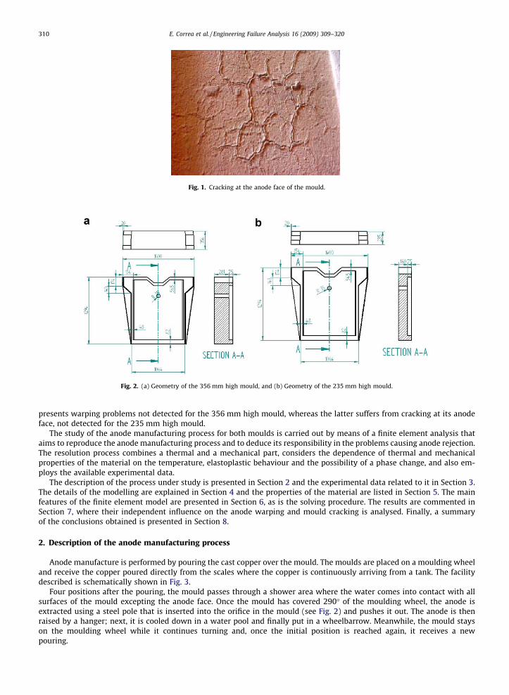
Fig. 1. Cracking at the anode face of the mould.
Fig. 2. (a) Geometry of the 356 mm high mould, and (b) Geometry of the 235 mm high mould.
310 E. Correa et al. / Engineering Failure Analysis 16 (2009) 309–320
presents warping problems not detected for the 356 mm high mould, whereas the latter suffers from cracking at its anodeface, not detected for the 235 mm high mould.
The study of the anode manufacturing process for both moulds is carried out by means of a finite element analysis thataims to reproduce the anode manufacturing process and to deduce its responsibility in the problems causing anode rejection.The resolution process combines a thermal and a mechanical part, considers the dependence of thermal and mechanicalproperties of the material on the temperature, elastoplastic behaviour and the possibility of a phase change, and also em-ploys the available experimental data.
The description of the process under study is presented in Section 2 and the experimental data related to it in Section 3.The details of the modelling are explained in Section 4 and the properties of the material are listed in Section 5. The mainfeatures of the finite element model are presented in Section 6, as is the solving procedure. The results are commented inSection 7, where their independent influence on the anode warping and mould cracking is analysed. Finally, a summaryof the conclusions obtained is presented in Section 8.
2. Description of the anode manufacturing process
Anode manufacture is performed by pouring the cast copper over the mould. The moulds are placed on a moulding wheeland receive the copper poured directly from the scales where the copper is continuously arriving from a tank. The facilitydescribed is schematically shown in Fig. 3.
Four positions after the pouring, the mould passes through a shower area where the water comes into contact with allsurfaces of the mould excepting the anode face. Once the mould has covered 290� of the moulding wheel, the anode isextracted using a steel pole that is inserted into the orifice in the mould (see Fig. 2) and pushes it out. The anode is thenraised by a hanger; next, it is cooled down in a water pool and finally put in a wheelbarrow. Meanwhile, the mould stayson the moulding wheel while it continues turning and, once the initial position is reached again, it receives a newpouring.

Fig. 3. Mechanical system for anode manufacture.
E. Correa et al. / Engineering Failure Analysis 16 (2009) 309–320 311
3. Experimental data
The manufacturing process of a single anode, referred to as ‘operation cycle’ from now on, can be divided, from the pointof view of the mould, into four different stages, described in the last section:
s Stage I: copper pouring and progression of the mould to the fourth position of the moulding wheel.
s Stage II: shower area.
s Stage III: progression of the mould to the extracting position of the anode.
s Stage IV: progression of the mould to the initial pouring position.
Experimental data available for each stage as well as some other information useful for the subsequent analysis are listednext:
� Approximate duration of the four stages of the anode manufacturing process, relevant for this study:s Stage I: duration: 1000.s Stage II: duration: 70.s Stage III: duration: 30.s Stage IV: duration: 20.
� Thermal datas Temperature at the anode face of the mould during the anode manufacturing process:
– Initial measured temperature (before pouring): 90 �C.– Temperature measured at anode extraction: 150 �C.
s Anode temperature:
– Temperature measured before entering the shower area: 730 �C.– Temperature measured after the shower area: 170 �C.The above experimental thermal data are provided by the manufacturer, who specifies that temperatures are measured ata single point. This value is considered to be representative of the thermal state of the whole surface (anode face of the mouldor surface of the anode in contact with the mould as appropriate) due to the high thermal conductivity of copper.
� Warping of the 235 mm high mould. The rapid appearance of a rough warping of 4 mm (in the first operation cycles) istypically observed by the manufacturer, and increases only slightly for later cycles.
� Production. Each mould is used to produce 3 anodes per day (3 operation cycles) over 60 days. After this period the mouldis rejected by the manufacturer.
Based on the information contained in the former paragraph a period of 60 working days is chosen for the numerical anal-ysis. The numerical calculations for 60 working days will enable warping predictions to be made during this period and willbe compared with the experimental data.
312 E. Correa et al. / Engineering Failure Analysis 16 (2009) 309–320
4. Modelling
As both objectives of analysis in this study, anode face cracking and mould warping, are inherently associated to themould, the finite element model designed only reproduces the mould’s geometry. This is due to the fact that both the warp-ing and the nerves of the anode are a reproduction of the warping and the cracking of the anode face of the mould itself.
The presence of the anode over the mould during the anode manufacturing process has been taken into account by con-sidering the suitable thermal boundary conditions (described later) imposed at each stage of the manufacturing process, bythe temperature experienced on the anode face of the mould.
The analysis is carried out in two phases: first a non-linear and transient thermal one, which provides a complete profileof temperatures affecting the whole mould during the anode manufacturing process; and a second non-linear and quasi-sta-tic mechanical analysis that aims, using as input data the results of the thermal analysis, to describe the stress and displace-ment state of the mould associated to the anode manufacture. Both analyses present a non-linear character due, on one hand,to the thermal dependence of the material properties and, on the other, the elastoplastic mechanical behaviour of copper.
Warping predictions are correspondingly carried out by means of the displacement results of the mechanical analysis ofthe model described, while the influence of the anode manufacture on the cracking of the anode face of the mould is ana-lysed by means of the stress results.
The lack of experimental data related to the mould temperature in some stages of the manufacturing process has made itnecessary to establish several hypotheses affecting the thermal boundary conditions of the mould during this process. As aconsequence of these hypotheses, the details of the manufacturing process described and the available experimental data, asimplified operation cycle has been designed, aiming to reproduce, in a sufficiently approximate way, the thermal evolutionof the mould in each real operation cycle of the moulding wheel.
The description of the simplified operation cycle is presented next, the hypotheses carried out being suitably clarified:Stage I: duration: 1000. This stage aims to model the sudden thermal increase suffered by the anode face of the mould as a
consequence of the copper pouring. The anode face, initially at 90 �C, is considered at the end of this step to reach 730 �C. Theanalysis is also carried out assuming other values for this temperature, in particular, 500 �C and 300 �C, the best fitting of thenumerical results to the experimental ones occurring for the 730 �C hypothesis, as will be demonstrated later on.
Stage II: duration: 70. This stage corresponds to the period in which the set formed by the mould and the anode passesthrough the shower area. Based on the experimental data, the temperature at the anode face of the mould at the end of thisstep has been considered to be equal to 170 �C.
Stage III: duration: 50. This stage attempts to model the cooling period in environmental conditions of the mould–anode set until the anode is extracted, and the empty mould later returns to its initial position on the moulding wheel.The final temperature of the anode face of the mould in this step has been taken equal to 90 �C as the experimental datasuggest.
The carrying out of the numerical analysis for the simplified operation cycle described above results in temperatureprofiles for the model that, as has already been stated, are used as input data for the subsequent structural analysis. Thissecond analysis will consider the consecutive application of 60 operation cycles (the equivalent of 20 working days). Theresults provided by the analysis allow the warping suffered by the mould after each of these cycles to be predicted. An exten-sion of these results will also make it possible to develop a long-term prediction, in particular for 180 cycles (60 workingdays).
Moreover, for the mechanical analysis, in addition to the results of the thermal analysis, it is necessary to consider theappropriate displacement boundary conditions. In this case these conditions are imposed merely to avoid the rigid bodymovements of the mould.
With reference to the thermal analysis, heat transfer mechanisms (conduction, convection and radiation) acting over themould–anode set during the whole anodes manufacturing process, have obviously to be considered in the simplified oper-ation cycle. Particular features of these mechanisms considered for each stage are detailed next:
Stage I:
� Conduction through the mould.� Radiation of all surfaces of the mould, except the support face and the anode face. In order to simplify the radiation pro-
cess it has been considered that the mould irradiates towards a single solid whose temperature is Tirr = 30 �C.� Convection towards the environment of all mould surfaces except the anode face (convection heat transfer coefficient,
h = 15 W/m2 K and Tenv = 30 �C).
Stage II:
� Conduction through the mould.� Radiation of all surfaces of the mould except the support face (the face in contact with the moulding wheel) and the anode
face (Tirr = 30 �C).� Forced convection of all mould surfaces except the anode face (h = 3500 W/m2 K).

E. Correa et al. / Engineering Failure Analysis 16 (2009) 309–320 313
Stage III:
� Conduction through the mould.� Radiation of all surfaces of the mould except the support face and the anode face (Tirr = 30 �C).� Convection towards the environment of all mould surfaces except the anode face (h = 15 W/m2 K and Tenv = 30 �C).
5. Material properties
The moulds are made of copper, identification C11XXX, the chemical composition of which is: O2: 0.15%, As: 0.10%, Pb:0.03%, S: 40 ppm, Cu: 99.71%. Thermal and mechanical properties have been obtained from the literature [4–8]. Copper den-sity is 8900 Kg/m3 [5].
5.1. Thermal properties
Table 1 shows values of the thermal conductivity, specific heat capacity and enthalpy of copper for different temperatures[5–7].
5.2. Thermoelastic properties
The values of the coefficient of thermal expansion are shown in Table 2 for different temperatures.Ideal elastoplastic behaviour has been considered for the material. Elasticity modulus has been considered to remain con-
stant in a first segment and equal to the room temperature value, E = 115 GPa [5,8], decreasing linearly from 200 �C on untilreaching fusion point, Fig. 4. Due to some numerical problems a zero value of the Elasticity modulus for fusion temperaturecan not be considered, so at this point the value chosen has been E = 115 10�3 GPa. Poisson coefficient, m, has been consideredto be constant with the temperature: m = 0.33. Elastic limit evolution, rE, has been considered to be similar to that of the Elas-ticity modulus, Fig. 4, i.e. constant and equal to the room temperature value in a first segment, rE = 85 MPa [5,7], anddecreasing linearly from 200 �C on until reaching a value at the fusion point of rE = 85 � 10�3 MPa.
6. Finite element model
The finite element code ANSYS v.8.0 [8] has been used for the numerical analysis. The mesh employed for the 356 mmhigh mould is shown in Fig. 5; that corresponding to the 235 mm high mould being similar. The mesh is formed by 8240nodes and 6422 elements.
The analysis is undertaken on the assumption that both problems, thermal and mechanical, are uncoupled. Consequently,and as was mentioned above, the thermal problem is solved in the first place, obtaining as a result the evolution of the
Table 1Thermal properties as a function of the temperature
T (�C) Kt (W/m K) Cp (J/Kg K) H (KJ/m3)
0 401 385 0200 413 356 634000400 393 397 1600000600 379 417 1960000800 366 433 320000
1000 352 451 –1080 – – 37400001084 – – 57900001200 339 480 6230000
Table 2Coefficient of thermal expansion as a function of the temperature, [5,7]
T (�C) a (�C�1)
0 1.70 � 10�5
200 1.73 � 10�5
450 1.77 � 10�5
700 1.80 � 10�5
950 1.83 � 10�5
1200 1.90 � 10�5

0
50
100
150
0 500 1000 1500T (º)
E (
GP
a)
0
50
100
150
0 500 1000 1500T (º)
σE (
GP
a)
Fig. 4. Elasticity modulus E (a) and elastic limit, rE, (b), versus temperature.
Fig. 5. Mesh employed for the finite element analysis of the 356 mm high mould.
314 E. Correa et al. / Engineering Failure Analysis 16 (2009) 309–320
temperature profile of the whole solid. These temperatures act as external actions (modelled as volume loads) for the struc-tural problem.
As thermal and mechanical properties depend on the temperature and elastoplastic behaviour of the material is consid-ered, both problems (thermal and structural) are non-linear. Their solution is obtained making use of a Newton–Raphsonalgorithm.
SOLID70 elements [8] have been used in the thermal problem to mesh the solid and to consider heat conduction,while convection has been modelled as a surface load and radiation is included in the analysis by the addition of SURF152elements [8]. SOLID45 elements [8] have been used to model the elastoplastic behaviour of the material in the mechanicalanalysis.
7. Results
As was explained in Section 1, the analysis of the manufacturing process of the anodes pursues a double objective: thestudy of the influence of this process in the cracking of the mould and the prediction of the accumulated warping duringthe operation period of the mould (60 days). It was also noted that the first problem seems to be exclusively associatedto the 356 mm high moulds, whereas the second problem affects the 235 mm high moulds.
Results related to the warping of the moulds are presented in Section 7.1, whereas those relative to the aggravation of thecracking are presented in Section 7.2.

Fig. 6. Reference points for warping measurement.
E. Correa et al. / Engineering Failure Analysis 16 (2009) 309–320 315
7.1. Warping analysis
Excessive warping is the main cause of rejection for anodes made in the 235 mm high mould, and in this section the finiteelement model will be used to predict it, it being possible to check the reliability of the predictions by comparing them withthe warping level measured experimentally. A warping prediction for the 356 mm high mould will also be presented in thisSection, a lower warping level being envisaged in this case and therefore not seriously affecting the anode production.
The numerical model aims to analyse the mechanical evolution of a particular mould (either a 235 mm high mould or a356 mm high mould) while being subjected to 180 ‘operation cycles’ (these cycles being described in Section 4), which (asdescribed in Section 3) correspond to a production per mould of 3 cycles/day during a 60 day working period. The results ofthe analysis allow the evolution of the warping of the anode face of the mould to be calculated and later compared with theavailable experimental data.
7.1.1. 235 mm high mouldWarping has been calculated as the maximum difference in uy displacement between points in the anode face of the
mould. A first checking of the numerical results showed that the minimum displacement uy took place in a zone near theboundary of the orifice of the mould, whereas the maximum took place in the lower corner of that face. The points takenas references for the calculations in both the 235 mm high mould and the 356 mm high mould are highlighted in Fig. 6.
Once the reference points are located (A and B, respectively) the warping evolution, (uy(A) � uy(B)), can be calculated. Thewarping of the anode–mould set not only varies as the number of cycles increases, but also over one single cycle. The results
0
0.5
1
1.5
2
2.5
3
3.5
4
4.5
5
0 10 20 30 40 50 60
Time (operation cycles)
War
ping
(m
m)
0
0.5
1
1.5
2
2.5
3
3.5
4
4.5
5
0 10 20 30 40 50 60
Time (operation cycles)
War
ping
(m
m)
730 ºC500 ºC
Fig. 7. Warping evolution of the 235 mm high mould for 20 working days (60 cycles). (a) Results for the 730 �C hypothesis, and (b) comparison betweenresults of the 730 �C and 500 �C hypotheses.

316 E. Correa et al. / Engineering Failure Analysis 16 (2009) 309–320
presented here correspond to the evolution of the warping with the number of cycles, numerically measuring the warpingpresented for each cycle when the anode is extracted from the mould.
For the 235 mm high mould the evolution of uy(A) � uy(B) was first calculated for 60 cycles (20 working days), the resultsbeing presented in Fig. 7a and b.
Previous to the analysis of these results it is necessary to remember that, as explained in Section 4, in the absence of suf-ficient experimental data relative to the thermal process suffered by the mould during the operation cycle, a simplified oper-ation cycle has been designed. This simplified operation cycle included a hypothesis concerning the temperature of theanode face of the mould at the end of Stage I (see Section 4). The possibilities for this temperature cover a wide range from730 �C (the first experimental temperature measured for the anode) to 300 �C. The results presented in Fig. 7a correspond tothe 730 �C hypothesis, while a comparison between the results provided by the 730 �C and 500 �C hypotheses is included inFig. 7b.
Looking first of all at Fig. 7a, the warping evolution seems to increase very quickly in the first operation cycles, reaching4 mm after 6 cycles. From this moment on the slope of the curve smooths considerably, warping then increasing very slowlyuntil the end of the period considered. This fact is in accordance with the experimental evidence (see Section 3).
The results shown in Fig. 7a also show that the accumulated warping at the end of 20 working days is about 4.5 mm. Asexplained at the end of Section 3, the evolution of the warping for a period of 60 working days is required. In view of the highcomputational time required for the solving of each operation cycle and the asymptotic tendency shown by the results plot-ted in Fig. 7a, also supported by the experimental evidence, the warping prediction for 60 days has been obtained by meansof the least squares method, using, as a basis, the warping results for the last 18 cycles considered in Fig. 7a. The least squaresline achieved is
W ¼ 4:556� 1425:276nþ 312:864
ð1Þ
where n represents the number of cycles (each operation cycle is equivalent to 120) and W is the predicted warping (in mm).In agreement with this adjustment the warping predicted for 60 working days (3 cycles per day) is 4.50 mm. In any case, andaccording to the adjustment performed, as the number of cycles increases the warping tends to the asymptotic valueW = 4.556 mm.
Focusing now in Fig. 7b, the results for a different hypothesis for the temperature of the anode face of the mould at theend of Stage I (in particular, 500 �C) are additionally included. It can be checked for this case that the maximum warpingobtained is 2.8 mm, a value maintained roughly constant from almost the first operation cycle. Though not included inthe Figure for the sake of simplicity, the same tendency was observed when taking as a datum a temperature of 300 �C,the warping obtained in this case being even lower.
In view of the best fit with the experimental results (a final warping no lower than 4 mm) provided by the 730 �C hypoth-esis, in comparison with the 500 �C and the 300 �C results, this first temperature was finally chosen for the analysis.
7.1.2. 356 mm high mouldAs explained at the beginning of this section, the warping analysis has also been carried out on the model of the 356 mm
high mould, establishing the same considerations and hypothesis as for the case of the 235 mm high mould. The final tem-perature chosen at the end of Stage I for the calculations has been, as in the former case, 730 �C.
Warping results for 20 working days work are shown in Fig. 8. It can be observed that, as in the case of the 235 mm highmould, warping rapidly increases in the first operation cycles, later evolving more smoothly and approximately correspond-ing to a line whose slope is less marked than that obtained for the 235 mm high mould.
0
0.5
1
1.5
2
2.5
3
3.5
4
4.5
5
0 10 20 30 40 50 60
Time (operation cycles)
War
ping
(m
m)
Fig. 8. Warping evolution for 20 working days and 730 �C hypothesis (356 mm high mould).
E. Correa et al. / Engineering Failure Analysis 16 (2009) 309–320 317
The accumulated warping for 20 working days is about 2.75 mm. The extension of the results obtained for the last 18cycles to a long working period is again carried out by means of the corresponding least square adjustment which, in thiscase, follows the equation:
W ¼ 2:738� 2203:704nþ 804:840
ð2Þ
where n again representing the number of cycles and W the predicted warping (in mm). In agreement with this fitting, thepredicted warping for 60 working days (3 cycles per day) is 2.66 mm. In any case, and according to the adjustment per-formed, as the number of cycles increases the warping tends to the asymptotic value W = 2.738 mm. As expected, the valueof W obtained for this case is lower than in the 235 mm case. The predicted warping value is acceptable for the 356 mm highmould and therefore does not represent a serious cause of anode rejection.
7.2. Stress state analysis
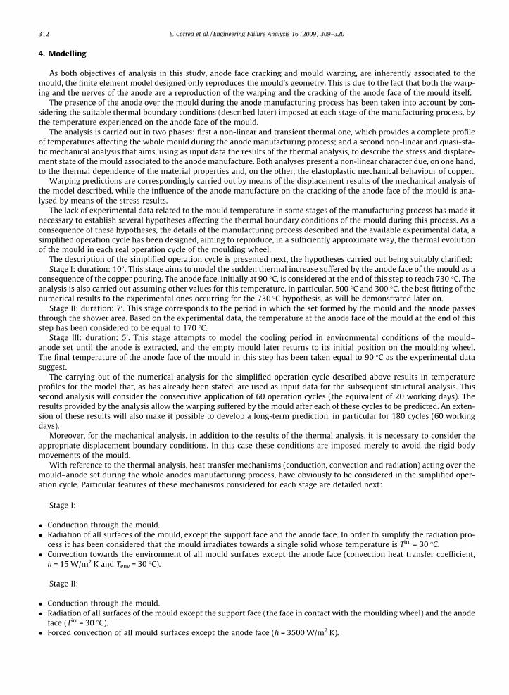
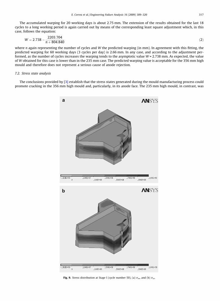
The conclusions provided by [3] establish that the stress states generated during the mould manufacturing process couldpromote cracking in the 356 mm high mould and, particularly, in its anode face. The 235 mm high mould, in contrast, was
Fig. 9. Stress distribution at Stage I (cycle number 50), (a) rxx, and (b) rzz.
318 E. Correa et al. / Engineering Failure Analysis 16 (2009) 309–320
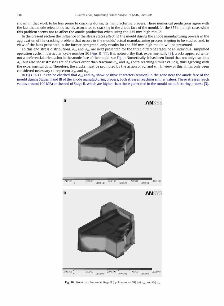
shown in that work to be less prone to cracking during its manufacturing process. These numerical predictions agree withthe fact that anode rejection is mainly associated to cracking in the anode face of the mould, for the 356 mm high case, whilethis problem seems not to affect the anode production when using the 235 mm high mould.
In the present section the influence of the stress states affecting the mould during the anode manufacturing process in theaggravation of the cracking problem that occurs in the moulds’ actual manufacturing process is going to be studied and, inview of the facts presented in the former paragraph, only results for the 356 mm high mould will be presented.
To this end stress distributions, rxx and rzz, are next presented for the three different stages of an individual simplifiedoperation cycle, in particular, cycle number 50 (Figs. 9–11). It is noteworthy that, experimentally [3], cracks appeared with-out a preferential orientation in the anode face of the mould, see Fig. 1. Numerically, it has been found that not only tractionsryy but also shear stresses are of a lower order than tractions rxx and rzz (both reaching similar values), thus agreeing withthe experimental data. Therefore, the cracks must be promoted by the action of rxx and rzz. In view of this, it has only beenconsidered necessary to represent rxx and rzz.
In Figs. 9–11 it can be checked that rxx and rzz show positive character (tension) in the zone near the anode face of themould during Stages II and III of the anode manufacturing process, both stresses reaching similar values. These stresses reachvalues around 100 MPa at the end of Stage II, which are higher than those generated in the mould manufacturing process [3],
Fig. 10. Stress distribution at Stage II (cycle number 50), (a) rxx, and (b) rzz.

Fig. 11. Stress distribution at Stage III (cycle number 50), (a) rxx, and (b) rzz.
E. Correa et al. / Engineering Failure Analysis 16 (2009) 309–320 319
decreasing to about 60 MPa at Stage III. Maximum compressions, 100–110 MPa, take place in the inner part of the mould. Bycontrast, this behaviour changes at Stage I, the anode face and the support face of the mould remaining under compression,while the core stands under tension, the order of the tensions and compressions being the same as that corresponding toStages II and III. Notice that stresses occurring during Stage II in the anode face of the mould involve a bi-tensional stateof about 100 MPa. Taking as a reference the rE value at room temperature (80 MPa), the stress level reached at Stage IIcan then be considered as quite severe, and thus the idea of crack promotion which already arose during the manufacturingprocess of the mould becomes admissible.
Another fact, outside the limits of this paper, is the study of the implications of the change in sign during the operationcycle of the traction from compression to tension, which could originate a fatigue process in the defects already present inthe mould.
Finally, the evolution of the stress state of the 235 mm high mould during the manufacturing process of the anode hasalso been analysed, finding that the behaviour of the mould in this case shows the same pattern as the 356 mm high mould,the inclusion of the results here therefore being considered unnecessary.
Since the cracking problem is almost exclusively associated to the 356 mm high mould and in view of the similarity be-tween the stress states of both moulds during the anode manufacturing process, the appearance of cracking can not be asso-

320 E. Correa et al. / Engineering Failure Analysis 16 (2009) 309–320
ciated to the process presented here (excluding the growth of a pre-existing crack). Thus, the mechanical reasons for the ori-gin of the cracks must be investigated in the manufacturing process of the mould itself [3].
8. Conclusions
The manufacture of copper anodes for electrolysis constitutes a complex thermal and mechanical process that involves alarge variety of variables and parameters, the value of a significant number of them being unknown. This fact has made itnecessary to establish some hypotheses as well as to adjust some parameters in order to be able to build up a numericalFEM model. In any case, the formulation of the hypotheses has always been reasoned and their validity as well as that ofthe adjustment of the parameters has been checked through the available experimental evidence related to the process un-der study.
Two different causes of the rejection of anodes have been analysed in the frame of the manufacturing process of the an-ode: the bending/warping of the mould and the cracking of the anode face of the mould.
With reference to the warping analysis, a problem almost exclusively related to the 235 mm high mould, the numericalanalysis of this mould allows a qualitative analysis of the warping of the mould to be performed. This analysis shows that thefirst cycles are critical from the warping point of view in that the warping seems to increase very quickly in the first 6 cycles,reaching a value of 4 mm, whereas this tendency smooths out for later cycles, providing a warping prediction for a twomonth working period of 4.5 mm. The quantitative predictions made for both the first cycles and the final period of usageof the mould provide a good adjustment to the experimental observation of the real process, thus making it possible to per-form feasible numerical predictions using the model developed.
The numerical warping analysis for the 356 mm high mould has been carried out maintaining the same parameters as inthe 235 mm case. In a similar way to the 235 mm case, the warping evolution presents two different stages, an initial quickgrowth and a approximately linear evolution from the first 6 cycles on. This analysis allows a warping prediction to be madefor a two-month period of 2.66 mm, which is, as expected, lower than the level reached for the 235 mm case.
With reference to the tensional causes of the cracking of the anode face of the mould, and although this problem is mainlyassociated to the manufacturing process of the mould included in [3], an analysis of the influence of the stress state on thecracking of the anode face of the mould during the manufacturing process of the anodes has been carried out in this paper.The analysis of the stress state during the operation cycles has shown that the growth of the existent cracks originating fromthe manufacturing process of the mould is favoured due to the presence of tensions in the anode face of the mould duringStages II and III of the working cycle. The effect of these tensions would be added to that originating in the mould manufac-turing process, favouring crack growth in the zone in which they initially appeared. The development of new cracks couldalso be promoted once the stress level reached during the manufacturing process of the mould is considered to be severeenough. These conclusions agree with the experimental evidence.
Finally, the results obtained by the studies performed prove the finite element model presented to be an effective anduseful tool for the design of new moulds.
Acknowledgements
The authors are grateful to the Atlantic-Copper staff for their help and collaboration, and wish to thank Mr. José MiguelQuintana and Mr. Eloy Crespo in particular.
References
[1] Quintana JM, Palacios Crespo E. Copper moulds design optimization at the Atlantic Copper smelter. European Metallurgical Conference (EMC-2007)Copper Committee, Ulm, Germany; March 2007.
[2] Quintana JM, Palacios M, Crespo E. Copper moulds design optimization at the Atlantic Copper smelter. European Metallurgical Conference (EMC-2007),Düsseldorf, Germany; June 2007.
[3] Blázquez A, Correa E, Estefani A, París F, Cañas J. Fabrication stresses inducing cracking of a mould made of copper. Eng Fail Anal 2009;16(1):358–70.[4] Anonymous. Hojas de datos del Cobre, Centro Español de Información del Cobre; 1970.[5] Anonymous. ASM metals handbook, vol. 2. Properties and selection: nonferrous alloys and special-purpose materials; 1992.[6] Incropera FP, De Witt DP. Fundamentals of heat and mass transfer. New York: John Wiley and Sons; 1985.[7] Anonymous. ASM metals handbook, vol. 1, Metals park, OH; 1990.[8] Anonymous. ANSYS. User’s manual, v8.0; 2003.
Copyright © 2022 FDOKUMEN