Minimising systematic errors in DEMs caused by an inaccurate lens model

Improving correlation-based DEMs by image warping and facade correlation
Christophe VestriISTAR & INRIA/Robotvis
06560 Sophia-Antipolis, [email protected]
Frederic DevernayI3S/IMAGES, Universite de Nice
Sophia-Antipolis, [email protected]
Abstract
We present in this article a system which improves aDEM. The method reconstructs all the facades of the build-ing and then, corrects the initial DEM by deleting the pointsof the roofs which pass over the boundaries defined by thefacades. We correct the shapes of the buildings with theinitial photographs to have sharp contours. The proposedapproach does not use any a priori information about theorientation of the facades and the shape of the buildings.We present results with synthetic and real images.
1 Introduction and related work
This paper presents a system to improve a Urban DEM(Digital Elevation Model) made by correlation-based stereofrom multiple aerial photographs. This system uses thesame images to correct the shape of the building a posteri-ori. In aerial photography, a correlation algorithm will usu-ally succeed in the reconstruction of the horizontal featuresof the scene (roofs and ground) because they are fronto-parallel surfaces. But the same algorithm will fail with ver-tical features (facades) which are very steep surfaces of thisscene. Without any assumption on the shape of the building,we propose to reconstruct all its facades by using warpedimages. Then, we improve the DEM by removing the pointsof the initial building which are over the facade boundaries.We first compare our technique with some of others
methods and particularly those which use images of facadesto verify, construct or refine a building model. A first classof methods is designed for large-scale applications as car-tography or telecom. These methods mainly use top viewsof the scene as aerial or satellite images, or aerial laser-scanning. Feature-based methods use hierarchical groupingand matching to reconstruct the model by using features,extracted from the images, of increasing complexity [1, 5].Nevatia uses walls and shadows for verification [6]. Adap-tive window correlation methods [4] work well on extract-ing roofs and ground, but they assume that depth discontinu-
ities are materialized by image contours. As the area-basedmethods, they cannot use facade images.The second class of methods is mainly designed for com-
puter graphics, virtual reality or architecture. These meth-ods aim at reconstructing an accurate building model (bothgeometrically and visually) and use mainly ground pho-tographs. Coorg and Teller use the space-sweep algorithmin [2] to recover horizontal lines from the facades, then theyreconstruct the model of the building and extract the mediantexture. In [3], Debevec et al. construct a coarse modelby hand, then they warp the initial images with respect tothe coarse model and refine the model by applying a simplecorrelation-based stereo algorithm. These two methods arecloser to our system than the first class of methods that usesaerial images as we do. We warp images so that facades ap-pear similar in a stereo pair, but we use an incidence count-ing technique to avoid the use of an initial building model.We describe our system in Section 2, and explain in Sec-
tion 3 the important parts of our system. Results are pre-sented with synthetic views and with aerial photographsover Berlin.
2 Motivation and overall strategy
Our global strategy to model building or a set of build-ings is composed of three main stages. The first stage is theconstruction of a dense and reliable DEM using a classicalcorrelation-based stereo method. The second stage is thesegmentation of this DEM into locally planar surfaces. Theobjective of this second stage is to describe the scene withsurface patches which correspond to the various facets ofthe buildings. The third and last stage is the vectorizationof the boundaries of each surface patch to obtain the finalmodel of the buildings. Errors in the DEM will have a largeimpact on the segmentation and vectorization stages. Thesystem we propose in this article corrects boundaries of thebuildings on the DEM to make easier the two last stages ofour global strategy.Facades represent an important surface in the different
image, especially near the image boundaries. Because they
are steep surfaces of the scene, they appear very distorted inthe images and a simple correlation-based stereo algorithmcannot recover these vertical surfaces. Besides, becauseof the difference in illumination between the roofs and theground (especially in shadows), the correlation-based stereowill enlarge the roofs in these areas. This paper presents asystem that uses the facade images of a building, taken intothe aerial photographs, to improve the initial correlation-based DEM. The framework of our system is: first, we con-struct new images of facades wherein a correlation-based al-gorithm can easily match facades and reconstruct them witha good geometric accuracy. Then, we correct the erroneouspoints of the DEM which pass over the facade boundaries.
��������
� O
��
����
��
P2 P1
ZY
��
X
����
��
Figure 1. Choice of images: �� is the verticaldirection and�� is the orientation of the facadein the horizontal plane OXY. ���� and ���� are theprojections of �� and �� at� in image �.
Let us suppose first that we know the orientation in thescene of the facades we want to extract (figure 1). The dif-ferent stages of our system are the followings:
1. Choosing two views of the facade. Because facades arenot viewed in the same way in all images, we need tochoose two images using some criterion (cf. 3.1).
2. Constructing the images of facades. These images arewarped images of the chosen couple of images. Thefacades have the same visual aspect on these images(cf. 3.2).
3. Matching by correlation and reconstruction. We ap-ply a simple correlation-based algorithm to match andreconstruct the 3D points of the facades.
4. Filtering out the erroneous 3D points. (cf. 3.4).
5. Improving the DEM. Finally, we use the 3D recon-structed points (for the defined orientation of facade)to improve the DEM.We simply dig in the DEMwherewe reconstruct a point (cf. 3.5).
To treat all the facades of a building, we use this algorithmon all the possible facade orientations in the scene, thusmaking no assumption on the building shape. A subsam-pling of the orientation space by 20� is enough to recoverall the facades. This system is not dependent on the numberof available images, the orientation of the facades, or theshape of the buildings.
3 Implementation
All the views of the scene are supposed to be calibrated.The initial DEM is made by fusion of several DEMs, each ofthem corresponding to the matching of two adjacent views.The list of image couples will be later used to conduct thechoice of images for a given orientation.To keep the computational time low, the whole process is
only applied to the neighborhood of a building: each build-ing or group of adjacent buildings can be automatically ex-tracted from the raw DEM. We now present the implemen-tation of each stage of the algorithm. This algorithm workson a given facade orientation: if there is a true facade forthis orientation, it extracts the points of the facade, filtersoutliers, and improves the DEM. The whole system usesthis algorithmwith all possible facade orientations, sampledby 20� and improves the DEM incrementally.
3.1 Choosing the images for a givenfacade orientation
First, we select two images from the list of image cou-ples available, where the facades are best viewed. We triedtwo criteria: (1) the images where the projected surface ofthe facade is of maximum size, (2) the angle between thenormal direction to the surface of the building and the di-rection toward the nadir of the images (vertical projectionof the optical center on the ground) is minimum (the viewmust be in the axis of the facade).We define two 3D unit vectors, the elevation vector ��
(orientation of the vertical) and the orientation vector�� (ori-entation of the facade in the horizontal plane), as shownin figure 1. These two vectors are defined on a 3D point� taken on the ground and in the middle of the DEM ofthe building. This couple of vectors corresponds to a unitfacade in the 3D scene. We compute the two 2D vectors���� and ���� in each image � which respectively correspondto the projections of our couple of 3D vectors �� and ��.���� � ����� ��� represents the orientation of the verticalat � in image � and ���� � ����� ��� represents the orien-tation of the facade at� in the same image.We define our two criteria for an image � as
�� � � ���� � ������ �� ����� � ����
� ������ ������

where � is the cross-product between two vectors. The ��
measure must be maximum and ��, which corresponds tothe cosine of the angle of the two vectors ���� and ����, mustbe minimum. We tried each of these criteria and the combi-nation of both to select the image couple. Best results werefound using only the �� criterion. We first select the im-age � corresponding to the maximum of ��. Among all theimage couples which contain this image, we select the onewith the maximum �� for the other image . This ensuresthat the two images are adjacent.
3.2 Construction of the new images
In this step, we want to construct a pair of rectified im-ages where the facades of a given orientation have the sameaspect for simplifying their match. The area of interest (ourbuilding) in each image is defined as the projection of arough envelope of our building, computed from the rawDEM. The deformation of the facade was induced by theprojection, each projection inducing a different deforma-tion of the same facade. Constructing images where facadeshave the same aspect can be achieved by compensating thisdeformation, as shown in the figure 2.
����
���
��������
���
��� ���
�
����
���
�
Figure 2. Facade transformation: ���� and ����are the projections of �� and �� at� in the rec-tified image �. ���� and ���� correspond to theirprojections in the rectified image �. The fa-cade transformation ��� from image � to im-age � consists in warping image � so that� ����� ����� maps to � ����� �����.
Because the images are rectified, the projections of 3Dvectors �� and �� in each image have the same componentsin the y-axis. We consider these vector projections to be lo-cally constant, since we are working at the scale of a build-ing in an aerial photograph (the projections are locally lin-ear). To get the same visual aspects for facades with thisorientation in both images, we apply the affine transform���, called facade transformation, which maps � ����� �����
to � ����� ����� (it is uniquely defined this way). Since bothimages are rectified, this transformation only modifies the �coordinate: the epipolar constraint is respected.We also studied the possibility to compute a transfor-
mation that would apply to the whole image instead of thelinearized version described before. Unfortunately, the re-search of such a transformation is equivalent to solve aPDE (Partial Differential Equation) which is not integrable.Working locally is equivalent to linearizing this function.To avoid resampling twice each image, we do not con-
struct rectified images. From initial views, we apply suc-cessively the rectification and the transformation of facade.The second transformation is only applied to one image (fig.2). We choose the other image as the one that has the max-imum �� (area criterion) score, so that the facade transfor-mation expands the image rather than stretching it.
3.3 Reconstruction of the facades
Figure 6 presents results of the matching process. Im-ages A, B and C show the matching process with imagesthat are rectified in the classical way. Images A, D and Epresent the results of the same matching process after fa-cade transformation. In the second case, the disparity sur-face which corresponds to the right facade is almost con-stant. The reconstructed 3D points of the facade will bemore dense and accurate. We see in figure 6 that we areable to match the points of the facade, but many matches inthe disparity map are erroneous data and must be rejected.
3.4 Filtering the reconstructed points
The filtering stage is composed of three passes: a filteron each disparity map using the normal vector to the 3Dsurface, a 2D filter using an accumulation map, and a 3Dfilter which takes into account the shape of the surface.First, in each disparity map, we compute the normal vec-
tor to the surface for each reconstructed 3D point by planefitting on its neighborhood (the neighborhood is consideredin the disparity image space). If the normal vector orienta-tion is too far from the chosen facade orientation, the corre-sponding 3D point is discarded (the threshold is 15�). Thenormal vector is then reprojected in the horizontal plane ofthe 3D space (we constrain facades to be vertical).The next filter uses an accumulation map, which is ref-
erenced in the same cartographic coordinates as the DEM.The reconstructed points are projected onto this map, and3D points which correspond to the same facade will accu-mulate at the same location in the map. The grid size isabout twice the resolution of initial images, and points withan accumulation lower than 2 are discarded.The last filter derives from the ideas of the perceptual
grouping. An interesting approach for surface reconstruc-
0 9
17
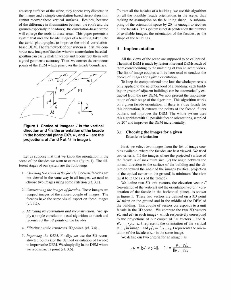
Figure 3. Filtering the points: The left arraypresents the voxels (large traits) and sub-cells (thin traits). The segment representsan hypothesis of facade. Grey cells are theselected cells by the Bresenham’s algorithm.The right array presents the count of vote ineach voxel.
tion from sparse data is described in [7]. Our 3D filter isa more simple system based on a vote filtering which givespriority to the vertical surfaces. We construct a 3D array incartographic coordinates. The voxel size is 1m in � and �and 3 meters in �.Each of the 3D points is linked to its corresponding
voxel, and the point votes for its facade neighborhood. Thefacade neighborhood is defined as a 3D rectangular patchcentered at the 3D point and oriented by its normal vector.The voting system uses a subsampling of the voxel space ata 20cm resolution, because the resolution of the 3D array isnot enough for computing a representative vote: we want afacade which passes through a corner of the voxel to have aless important vote than a facade which passes in the middleof the voxel.For voting along the facade, we first create an 6-meter
long horizontal segment centered at the 3D point and votefor the voxels where it passes through. We use the Bresen-ham’s algorithm to find all the sub-cells of the voxels wherethe segment passes over. Then, we replicate the vote alongthe segment to upper and lower voxels in the 3D array (2upper and 2 lower voxels). The weight of the vote (fig. 3) issimply the number of sub-cells marked by Bresenham algo-rithm which are inside the cell. We keep the 3D points forwhich the corresponding voxel has three 3D points inside,and which have a minimum number of 300 votes.
3.5 Improving the DEM
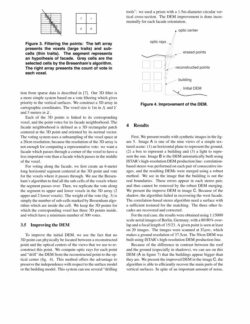
To improve the initial DEM, we use the fact that no3D point can physically be located between a reconstructedpoint and the optical centers of the views that we use to re-construct this point. We compute optic rays for each pointand “drill” the DEM from the reconstructed point to the op-tical center (fig. 4). This method offers the advantage topreserve the independencewith respect to the surface modelor the building model. This system can use several “drilling
tools”: we used a prism with a 1.5m-diameter circular ver-tical cross-section. The DEM improvement is done incre-mentally for each facade orientation.
optic rays
optic center
erased points
reconstructed points
building
Initial DEM
Figure 4. Improvement of the DEM.
4 Results
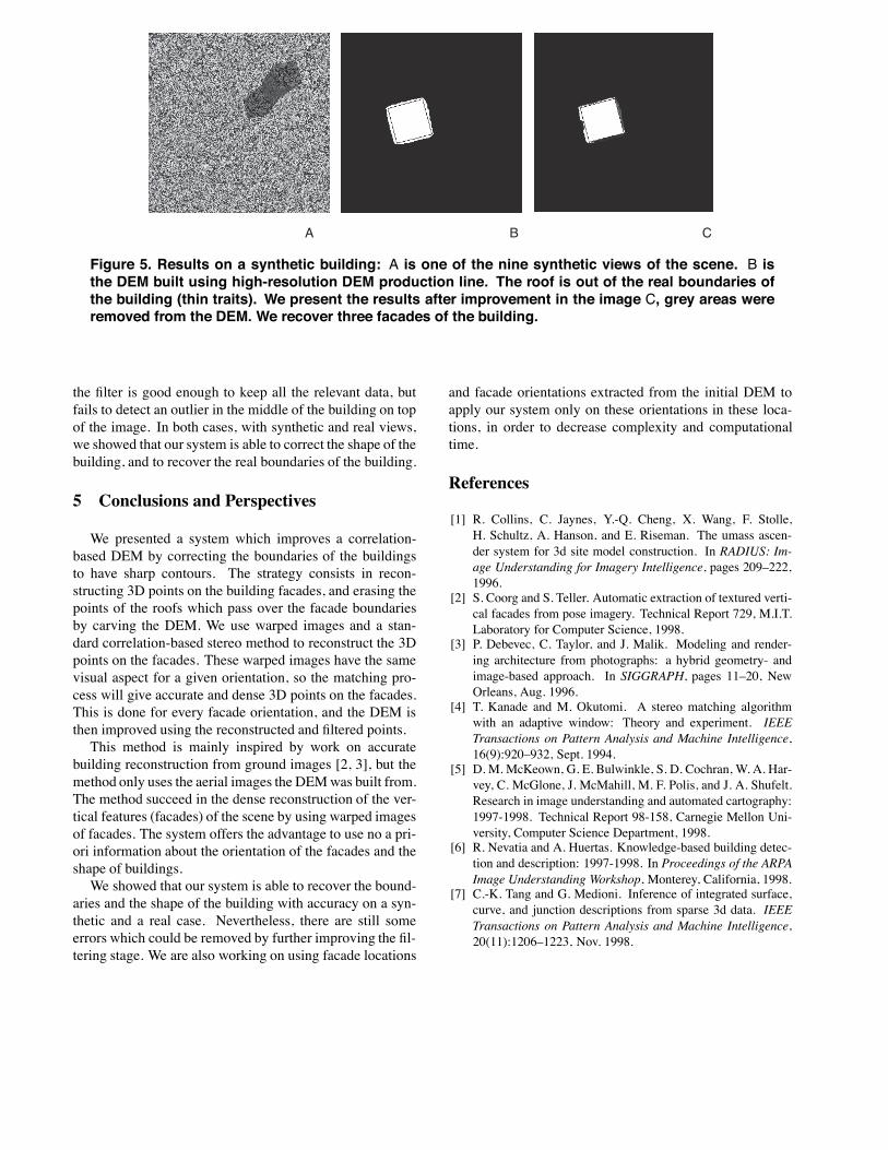
First, We present results with synthetic images in the fig-ure 5. Image A is one of the nine views of a simple tex-tured scene: (1) an horizontal plane to represent the ground,(2) a box to represent a building and (3) a light to repre-sent the sun. Image B is the DEM automatically built usingISTAR’s high-resolutionDEM production line: correlation-based stereo was performed on each pair of consecutive im-ages, and the resulting DEMs were merged using a robustmethod. We see in the image that the building is out thereal boundaries. These errors appear in each stereo pair,and thus cannot be removed by the robust DEM merging.We present the improve DEM in image C. Because of theshadow, the algorithm failed in recovering the west facade.The correlation-based stereo algorithm need a surface witha sufficient textured for the matching. The three other fa-cades are recovered and corrected.For the real case, the results were obtained using 1:15000
scale aerial images of Berlin, Germany, with a 80/80% over-lap and a focal length of 15/23. A given point is seen at leaston 20 images. The images were scanned at ���, whichmakes a ground resolution of 37.5cm. The 50cm DEM wasbuilt using ISTAR’s high-resolution DEM production line.Because of the difference in contrast between the roof
and the ground (especially in shadows), we can see on thisDEM (A in figure 7) that the buildings appear bigger thanthey are. We present the improved DEM in the imageC, thealgorithm is able to efficiently recover the main parts of thevertical surfaces. In spite of an important amount of noise,
A B C
Figure 5. Results on a synthetic building: A is one of the nine synthetic views of the scene. B isthe DEM built using high-resolution DEM production line. The roof is out of the real boundaries ofthe building (thin traits). We present the results after improvement in the image C, grey areas wereremoved from the DEM. We recover three facades of the building.
the filter is good enough to keep all the relevant data, butfails to detect an outlier in the middle of the building on topof the image. In both cases, with synthetic and real views,we showed that our system is able to correct the shape of thebuilding, and to recover the real boundaries of the building.
5 Conclusions and Perspectives
We presented a system which improves a correlation-based DEM by correcting the boundaries of the buildingsto have sharp contours. The strategy consists in recon-structing 3D points on the building facades, and erasing thepoints of the roofs which pass over the facade boundariesby carving the DEM. We use warped images and a stan-dard correlation-based stereo method to reconstruct the 3Dpoints on the facades. These warped images have the samevisual aspect for a given orientation, so the matching pro-cess will give accurate and dense 3D points on the facades.This is done for every facade orientation, and the DEM isthen improved using the reconstructed and filtered points.This method is mainly inspired by work on accurate
building reconstruction from ground images [2, 3], but themethod only uses the aerial images the DEMwas built from.The method succeed in the dense reconstruction of the ver-tical features (facades) of the scene by using warped imagesof facades. The system offers the advantage to use no a pri-ori information about the orientation of the facades and theshape of buildings.We showed that our system is able to recover the bound-
aries and the shape of the building with accuracy on a syn-thetic and a real case. Nevertheless, there are still someerrors which could be removed by further improving the fil-tering stage. We are also working on using facade locations
and facade orientations extracted from the initial DEM toapply our system only on these orientations in these loca-tions, in order to decrease complexity and computationaltime.
References
[1] R. Collins, C. Jaynes, Y.-Q. Cheng, X. Wang, F. Stolle,H. Schultz, A. Hanson, and E. Riseman. The umass ascen-der system for 3d site model construction. In RADIUS: Im-age Understanding for Imagery Intelligence, pages 209–222,1996.
[2] S. Coorg and S. Teller. Automatic extraction of textured verti-cal facades from pose imagery. Technical Report 729, M.I.T.Laboratory for Computer Science, 1998.
[3] P. Debevec, C. Taylor, and J. Malik. Modeling and render-ing architecture from photographs: a hybrid geometry- andimage-based approach. In SIGGRAPH, pages 11–20, NewOrleans, Aug. 1996.
[4] T. Kanade and M. Okutomi. A stereo matching algorithmwith an adaptive window: Theory and experiment. IEEETransactions on Pattern Analysis and Machine Intelligence,16(9):920–932, Sept. 1994.
[5] D. M. McKeown, G. E. Bulwinkle, S. D. Cochran, W. A. Har-vey, C. McGlone, J. McMahill, M. F. Polis, and J. A. Shufelt.Research in image understanding and automated cartography:1997-1998. Technical Report 98-158, Carnegie Mellon Uni-versity, Computer Science Department, 1998.
[6] R. Nevatia and A. Huertas. Knowledge-based building detec-tion and description: 1997-1998. In Proceedings of the ARPAImage Understanding Workshop, Monterey, California, 1998.
[7] C.-K. Tang and G. Medioni. Inference of integrated surface,curve, and junction descriptions from sparse 3d data. IEEETransactions on Pattern Analysis and Machine Intelligence,20(11):1206–1223, Nov. 1998.

A
D E
CB
Figure 6. Correlation of facades: A and B are rectified images of the building. C is the disparitymap, with A as reference, obtained by a correlation-based matching process. The roofs and groundare recovered correctly, whereas the right facade has a stair shape (it should be planar). D is Bwarped by the facade transformation. The right facade in D has the same visual aspect as in A. In thecorresponding disparity map (E), the disparity on the facade is almost constant. Image resolution is37.5cm.
A B C
Figure 7. Results on real buildings: A is the initial DEM of the building. B is the corresponding ortho-image. In A, the roof passes over the boundaries of the building (thin traits). C shows the resultafter improvement, grey areas were removed from the DEM, and we recover the real boundaries ofthe building.
Copyright © 2022 FDOKUMEN