
HOT RUNNER MOULDS - Meusburger
19
HOT RUNNER MOULDS QUICK & EASY CONFIGURATION
-
Upload
khangminh22 -
Category
Documents
-
view
3 -
download
0
Transcript of HOT RUNNER MOULDS - Meusburger

HOT RUNNER MOULDSQUICK & EASY CONFIGURATION
FH 63
F 50F 55
F 15F 25F 45
F 10F 20F 40
E 4500
F 50F 55F 60F 70F 90
2
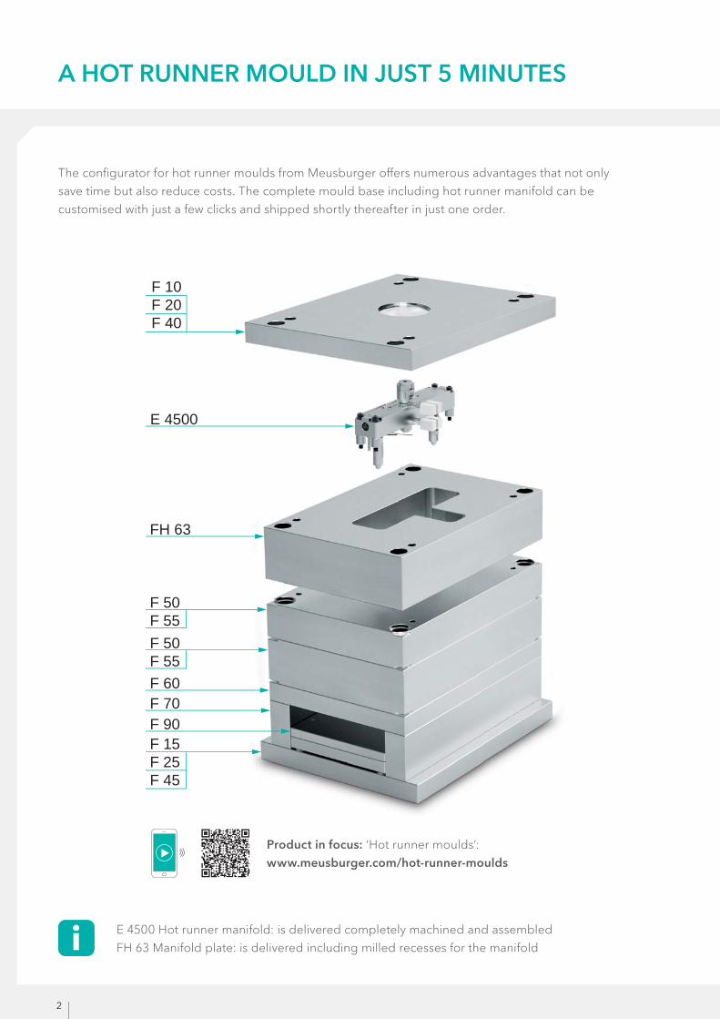
A HOT RUNNER MOULD IN JUST 5 MINUTES
The confi gurator for hot runner moulds from Meusburger off ers numerous advantages that not only
save time but also reduce costs. The complete mould base including hot runner manifold can be
customised with just a few clicks and shipped shortly thereafter in just one order.
E 4500 Hot runner manifold: is delivered completely machined and assembled
FH 63 Manifold plate: is delivered including milled recesses for the manifold
Product in focus: ‘Hot runner moulds’:
www.meusburger.com/hot-runner-moulds

3
3 VARIATIONS – THE CHOICE IS YOURS
With our standardised hot runner moulds, you have the choice between three diff erent manifold series.
IMT1
DEFLECTION MANIFOLD WITH 1 NOZZLE
Possible hole pattern (A):
min. 37.5 mm
max. 206.25 mm
IMT2
IN-LINE MANIFOLD WITH 2 NOZZLES
Possible hole pattern (A):
min. 25.0 mm
max. 206.25 mm
CMT4
CROSS MANIFOLD WITH 4 NOZZLES
Possible hole pattern (A):
min. 35.5 mm
max. 220.5 mm
4
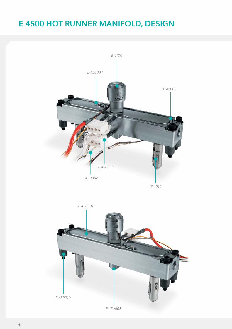
E 4010
E 450003
E 450010
E 450001
E 4100
E 450004
E 45002
E 450009
E 450007
E 4500 HOT RUNNER MANIFOLD, DESIGN

5
THE COMPONENTS IN DETAIL
E 4010: smartFILL MANIFOLD NOZZLE
» Including E 400 RA / E 400 RC / E 400 RE / E 400 RG nozzle tip
» Heater with 230 V, cable length 2000 mm » With integrated thermocouple type J, Fe-CuNi, DIN 43710, black+/white- » Max. injection pressure: 1800 bar
E 4100: HOT RUNNER SPRUE BUSH
» With integrated thermocouple type J, Fe-CuNi, DIN 43710, black+/white- » Heater with 230 V, cable length 2000 mm
E 450001: MANIFOLD
» Available in material grades 1.2311 / 1.2316 depending on the plastic used
E 450002: PIPE HEATING
» Power: 700 – 2800 W, depending on manifold size
E 450003: CENTRING PIECE
» Positions the manifold in the mould centre opposite the sprue bush
E 450004: 90° BENT THERMOCOUPLE
» Fe-CuNi (type J) » Thermocouple with kink protection spring » Connector length 5000 mm
E 450007: PROTECTIVE CONDUCTOR
» Connector length 2500 mm
E 450009: HEATER CONNECTION, COMPLETE
CONNECTOR CLAMP
» Allows a screwable connection of the electrical supply lines to any pipe heater » Two clamping options are provided on each connector clamp, so that by attaching a ‘bridge’ the pipe heater can be connected in parallel directly at the heating outlet
CONNECTING CABLE
» 2.5 mm² pure nickel cable, with glass fi bre insulation, 4-fold up to 300°C
E 450010: SPACER AND SCREW SET
» For the correct position and for screwing in the manifold
E 1300: ANTI-ROTATION PROTECTION
» Dowel pin with Ø 6 mm

6
1 3
4
1
2
3
4
3
4
2
PRODUCT FEATURES OF THEE 4010 smartFILL MANIFOLD NOZZLE
INNOVATIVE HEATING TECHNOLOGY
» Optimal heat transfer into the plastic used » Homogeneous temperature profi le on the entire nozzle length through diff erentiated power distribution
» Easy and fast change of heater and thermocouple due to intelligent clip lock
STREAMLINED MELT CHANNEL WITH HIGH-QUALITY SURFACE
» Optimal melt exchange since there are no dead spots » Low shear stress of the melt
» Good colour changing qualities
DIFFERENT GATE TYPES
» Flexible adjustment of the nozzle to diff erent applications and materials » Easily exchangeable, highly wear-resistant nozzle tips » Consistent nozzle lengths (l dimension) for diff erent types of gates
TORPEDO FOR OPTIMAL FLOW PROPERTIES
» The partitioning and re-merging of the melt take place in the hot area of the nozzle » Reduces the development of fl ow lines » Improves the optical and mechanical quality of the part
7
1.1730
1.2085
1.2312
E 2030
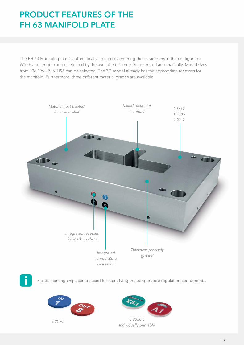
PRODUCT FEATURES OF THEFH 63 MANIFOLD PLATE
The FH 63 Manifold plate is automatically created by entering the parameters in the confi gurator.
Width and length can be selected by the user, the thickness is generated automatically. Mould sizes
from 196 196 – 796 1196 can be selected. The 3D model already has the appropriate recesses for
the manifold. Furthermore, three diff erent material grades are available.
Material heat-treated
for stress relief
Milled recess for
manifold
Integrated
temperature
regulation
Thickness precisely
ground
Integrated recesses
for marking chips
Plastic marking chips can be used for identifying the temperature regulation components.
E 2030 S
Individually printable
8
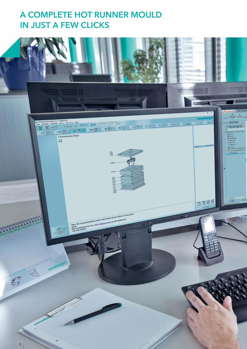
A COMPLETE HOT RUNNER MOULD IN JUST A FEW CLICKS
9
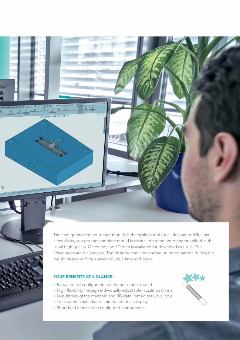
The confi gurator for hot runner moulds is the optimal tool for all designers. With just
a few clicks, you get the complete mould base including the hot runner manifold in the
usual high quality. Of course, the 3D data is available for download as usual. The
advantages are plain to see. The designer can concentrate on other matters during the
mould design and thus saves valuable time and costs.
YOUR BENEFITS AT A GLANCE:
» Easy and fast confi guration of the hot runner mould » High fl exibility through individually adjustable nozzle positions » Live display of the manifold and 3D data immediately available » Transparent costs due to immediate price display
» Short lead times of the confi gured components
10
»»
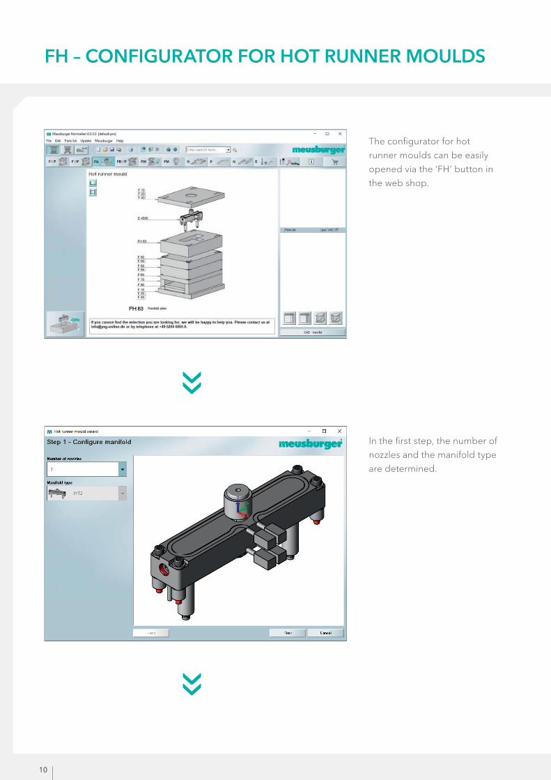
FH – CONFIGURATOR FOR HOT RUNNER MOULDS
The confi gurator for hot
runner moulds can be easily
opened via the ‘FH’ button in
the web shop.
In the fi rst step, the number of
nozzles and the manifold type
are determined.
11
»»
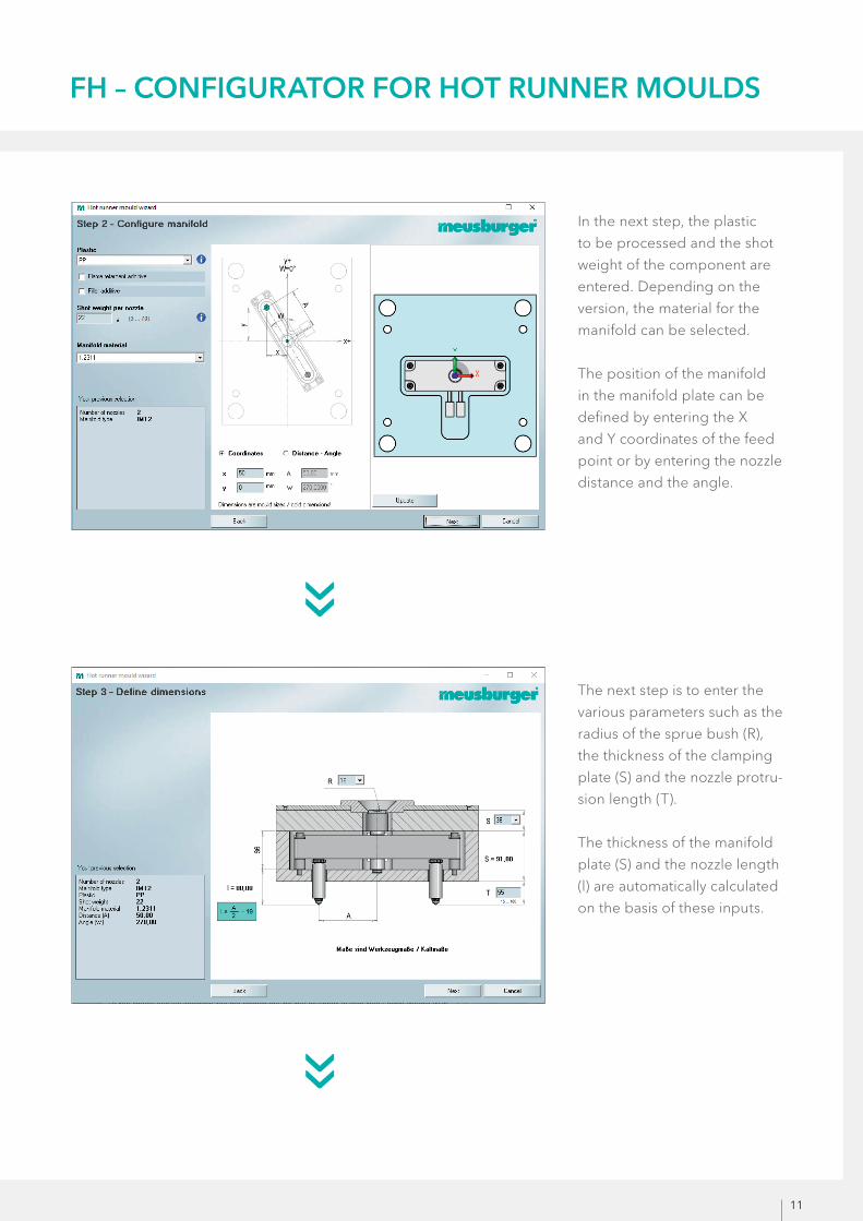
In the next step, the plastic
to be processed and the shot
weight of the component are
entered. Depending on the
version, the material for the
manifold can be selected.
The position of the manifold
in the manifold plate can be
defi ned by entering the X
and Y coordinates of the feed
point or by entering the nozzle
distance and the angle.
The next step is to enter the
various parameters such as the
radius of the sprue bush (R),
the thickness of the clamping
plate (S) and the nozzle protru-
sion length (T).
The thickness of the manifold
plate (S) and the nozzle length
(l) are automatically calculated
on the basis of these inputs.
FH – CONFIGURATOR FOR HOT RUNNER MOULDS

12
»»
FH – CONFIGURATOR FOR HOT RUNNER MOULDS
Now the nozzle tip is
selected.
For the correct gate type,
the information from the
PDF can be used (from
page 16).
The next step is to select the
desired mould size.
The dynamic display of the
mould size optimally shows
the manifold plate relative to
the manifold. In case of doubt,
the next larger or smaller
mould size can be selected.

13
»»
Finally, you get to the familiar
mould bases wizard where
you can select the material
of the manifold plate and the
rest of the plates and com-
ponents required to comple-
te your mould base.
In this step, the temperature
regulation system can be
confi gured.
The cooling connectors,
sealing plugs, and possi-
ble recesses for the E 2030
Marking chips can now be
selected.
NOTE:
An automatically generated
standard temperature regula-
tion system is only possible if
the angle (W) entered in step
3 is 0°, 90°, 180° or 270°.
FH – CONFIGURATOR FOR HOT RUNNER MOULDS
14
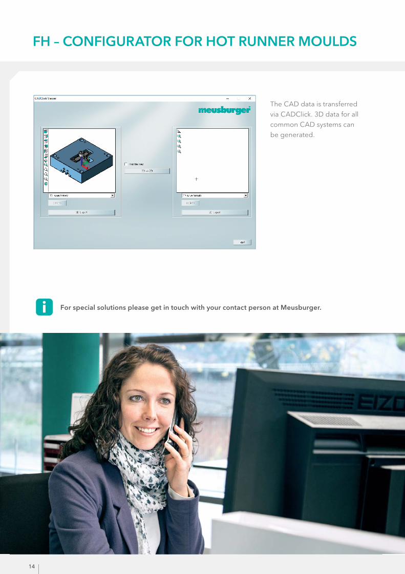
For special solutions please get in touch with your contact person at Meusburger.
The CAD data is transferred
via CADClick. 3D data for all
common CAD systems can
be generated.
FH – CONFIGURATOR FOR HOT RUNNER MOULDS

15
GUIDING ELEMENTS
The guiding elements are automatically selected in the
appropriate diameters and lengths and are shown in the
correct position in the 3D model.
ELECTRICAL COMPONENTS
Suitable electrical components can be directly ordered from the
shop. 3D data is also available here. This enables the designer
to integrate all components in the design and to keep an eye on
the dimensions.
profi TEMP+ HOT RUNNER CONTROLLER
With both innovative technology and space-saving design, the
profi TEMP+ Hot runner controller from PSG is sure to impress. In
addition to new intelligent functions like Smart Power Limitation
(SPL) and MoldCheck, the tried and trusted features are further
developed in the new hot runner controller. Due to the clearly
designed 7“ multi-touch screen, easy and intuitive operation is
guaranteed.
DELIVERY
The hot runner manifold is completely assembled and tested.
The mould base for the hot runner mould is not pre-assembled,
as in its standard version. This off ers the advantage of saving
valuable time by not having to take it apart. The components are
then available much faster for subsequent machining.
EVERYTHING FROM A SINGLE SOURCE
Product in focus: profi TEMP+:
www.meusburger.com/hot-runner

16
4 DIFFERENT NOZZLE TIPSFOR THE RIGHT GATE TYPE
All of the subsequent data is general recommendations based on our calculations and many years of
experience. We do not guarantee the accuracy of the information, as our products are only one part of
the production process. For unclear or diffi cult cases, please contact us.
E 400 RA
Nozzle tip, smartFILL ring gate, plunging
» For direct gating or gating through cold runner » Suitable for all thermoplastics with a medium to narrow processing window, including fi ller material and reinforcing fi llers
» Highly wear-resistant, interchangeable torpedo and nozzle head
E 400 RC
Nozzle tip, smartFILL ring gate, plunging with calotte
» Sprue scrap remains recessed 1 mm in the calotte » For direct gating or gating through cold runner » Suitable for all thermoplastics with a medium to narrow processing window, including fi ller material and reinforcing fi llers
» Highly wear-resistant, interchangeable torpedo and nozzle head
E 400 RE
Nozzle tip, smartFILL ring gate, plunging with extension
» With extension on nozzle head » Gating to free-form surfaces » Adjustment to the product's geometry » Sprue scrap with scrap cone » Suitable for all thermoplastics with a medium to narrow processing window, including fi ller material and reinforcing fi llers
» Highly wear-resistant, interchangeable torpedo and nozzle head
E 400 RG
Nozzle tip, smartFILL ring gate
» Good thermal separation from the mould by plastic isolation » For direct gating or gating through cold runner » Suitable for all thermoplastics with a medium to narrow processing window, including fi ller material and reinforcing fi llers
» Highly wear-resistant, interchangeable torpedo and nozzle head

17
E 400 RA E 400 RC E 400 RE E 400 RG
A B C A B C A B C A B (5) C (5)PE + ++ + + ++ + + ++ + ++ ++ +PP + ++ + + ++ + + ++ + ++ ++ +PPS ++ + + ++ + + ++ + + ++ ++ +PET (1) ++ + + ++ + + ++ + + ++ ++ +PBT (1) ++ + + ++ + + ++ + + ++ ++ +PPO (4) ++ + + ++ + + ++ + + ++ ++ +PA6 ++ + + ++ + + ++ + + ++ ++ +PA6.6 (1) ++ + + ++ + + ++ + + ++ ++ +POM-Co + + + + + + + + + ++ ++ +POM-H + + + + + + + + + ++ ++ +PMMA + ++ + + ++ + + ++ + ++ (5) ++ +ABS + ++ + + ++ + + ++ + ++ + +SAN + ++ + + ++ + + ++ + ++ + +PS (SB) + ++ + + ++ + + ++ + ++ + +PC + ++ + + ++ + + ++ + ++ (5) + +PES + ++ + + ++ + + ++ + ++ + +PSU + ++ + + ++ + + ++ + ++ + +PEI + ++ + + ++ + + ++ + ++ + +PVC soft + ++ + + ++ + + ++ + ++ (5) + +SMA ++ ++ + ++ ++ + ++ ++ + + + +PC/ABS + ++ + + ++ + + ++ + ++ + +PC/PBT ++ ++ + ++ ++ + ++ ++ + + + +PP-EPDM + ++ + + ++ + + ++ + ++ ++ +TPE-S + ++ + + ++ + + ++ + ++ ++ +TPE-U + ++ + + ++ + + ++ + ++ + +TPE-O - + + - + + - + + ++ ++ +
PE, PP, PS, TPE-OABS, SAN, ASA, PBT, PET,
POM-Co, PA, PPO, TPE-S, PP/EPDM, TPE-A, TPE-C
PC, PC/ABS, PC/PBT, PMMA, SMA, PES, PPS, PSU, PEI, PPO (PPE),
POM-H, PVC-soft, TPE-U
Ø2
7
E 400 RA 3 70 3 35 3 20E 400 RC 3 70 3 35 3 20E 400 RE 3 70 3 35 3 20E 400 RG 3 70 3 35 3 20
semi crystalline
amorphous
blend
elastomers
low viscosityη (Tset/3000 s-1) < 60Pa*s
medium viscosityη (Tset/3000 s-1)=(60-150)Pa*s
high viscosityη (Tset/3000 s-1) > 150Pa*s
Gate types min.[g]
max.[g]
min.[g]
max.[g]
min.[g]
max.[g]
The maximum shot weight is reduced by about 20% for reinforced and fi lled plastics with more than 20% fi ller content.
SHOT WEIGHT PER NOZZLE [G]
GATE TYPES
SELECTING THE CORRECT GATE TYPE
Material additives:
A without additives
B glass fi bre
C fl ame retardant
Material suitability:++ well suited
+ suitable
- not suitable
(1) Recommended minimum gate diameter = 1.2mm
(4) No Noryl GTX
(5) Insulating cap recommended
18
PP
PATPE-S
TPE-O (TPO)
PBTPETPESPSUABSPSPE
PP/EPDMSEBS
PCPC/PBTPC/ABS
SMATPE-U (TPU)
PMMAPEI
SANASAPPSPPO
POM-C
POM-H
TPE-U (TPU)
PVC-soft
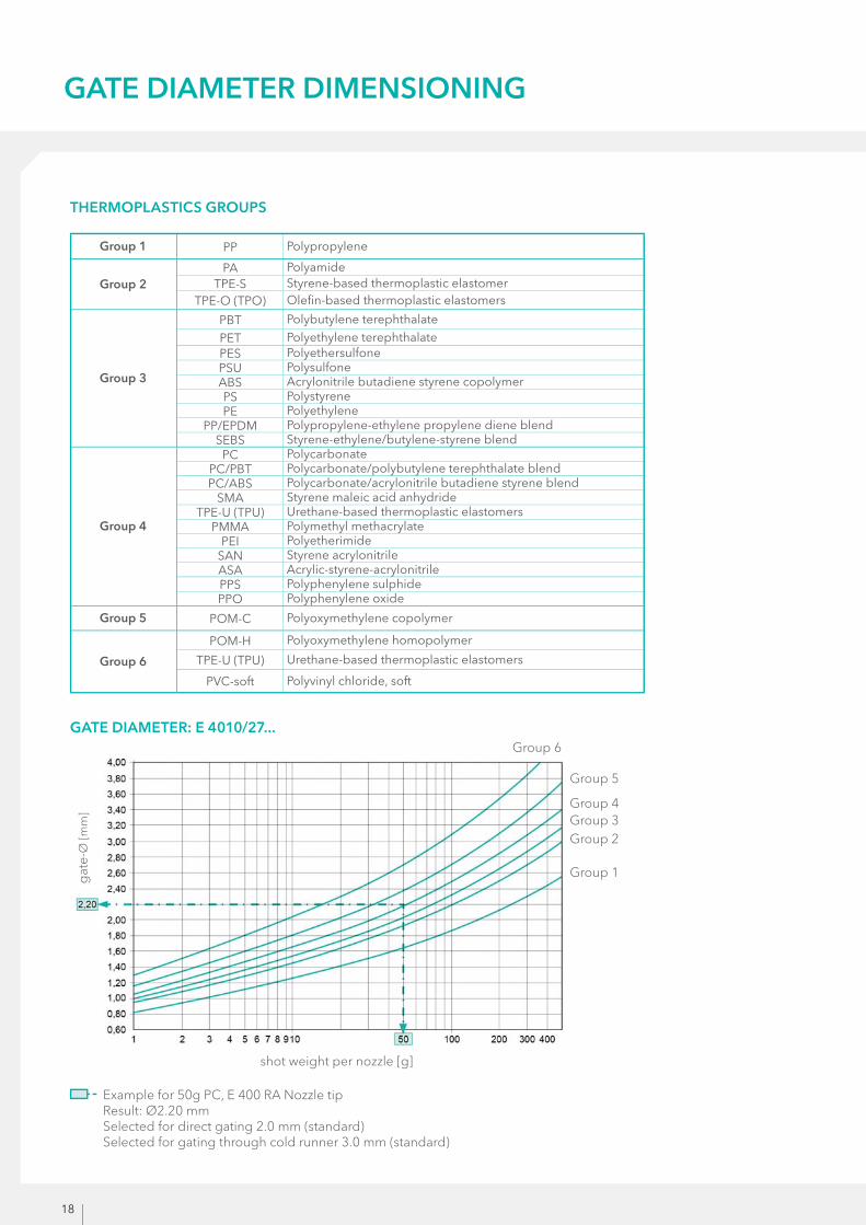
Example for 50g PC, E 400 RA Nozzle tip Result: Ø2.20 mm Selected for direct gating 2.0 mm (standard) Selected for gating through cold runner 3.0 mm (standard)
GATE DIAMETER: E 4010/27...
GATE DIAMETER DIMENSIONING
Group 1 Polypropylene
Group 2Polyamide Styrene-based thermoplastic elastomer Olefi n-based thermoplastic elastomers
Group 3
Polybutylene terephthalate Polyethylene terephthalate Polyethersulfone Polysulfone Acrylonitrile butadiene styrene copolymer PolystyrenePolyethylene Polypropylene-ethylene propylene diene blend Styrene-ethylene/butylene-styrene blend
Group 4
Polycarbonate Polycarbonate/polybutylene terephthalate blend Polycarbonate/acrylonitrile butadiene styrene blend Styrene maleic acid anhydride Urethane-based thermoplastic elastomers Polymethyl methacrylate Polyetherimide Styrene acrylonitrile Acrylic-styrene-acrylonitrile Polyphenylene sulphide Polyphenylene oxide
Group 5 Polyoxymethylene copolymer
Group 6
Polyoxymethylene homopolymer
Urethane-based thermoplastic elastomers
Polyvinyl chloride, soft
THERMOPLASTICS GROUPS
Group 1
shot weight per nozzle [g]
gat
e-Ø
[mm
]
Group 2Group 3Group 4
Group 5
Group 6
19
GATE DIAMETER DIMENSIONING
DETERMINING THE GATE DIAMETER:
The vestige quality is infl uenced by many factors such as: gate diameter, wall thickness, plastic type, volume
fl ow, part weight, temperature regulation / cooling in the gate area. Gate diameters that are too small cause
an inadmissibly high shear, high loss of pressure and high frictional heating. If the gate diameters selected
are too large, this results in inadmissibly high and poor-quality vestige.
RULE:
DIRECT GATING:
» Gate selection according to the graphic, taking the plastic type into consideration
GATING THROUGH COLD RUNNER:
» Gate diameter as large as possible (about 0.5 mm to 1 mm larger; take into consideration stringing and drooling)
The information on the dimensioning of the gate diameter includes only general recommendations, which are based on our calcula-
tions and extensive experience. We do not guarantee the accuracy of the information, as our products are only one part of a complex
production process. For unclear or diffi cult cases, please contact us.


![[The Stellar Ensemble com] The Kite Runner - Khaled Hosseini](https://static.fdokumen.com/doc/165x107/6345cb7c03a48733920b865d/the-stellar-ensemble-com-the-kite-runner-khaled-hosseini.jpg)