pr,t i tfl. WARPING STRESSES AND DEFLECTIONS IN CONCRETE SLABS
96
pr,t i tfl. WARPING STRESSES AND DEFLECTIONS IN CONCRETE SLABS
Transcript of pr,t i tfl. WARPING STRESSES AND DEFLECTIONS IN CONCRETE SLABS
pr,t
i tfl. WARPING STRESSES
AND
DEFLECTIONS IN CONCRETE SLABS


FINAL REPORT
WARPING STRESSES AND DEFLECTIONS IN CONCRETE SLABS
TO: K. B. Woods, DirectorJoint Highway Research Project
FROM: H. L. Michael, Assistant Director
May 21, 1953
File: 9-7-2Project: C-36-63B
Attached is a report entitled, "Warping Stresses and Deflectionsin Concrete Slabs," by Mr. M. E. Harr, Research Assistant, on our staff.The project was performed under the direction of Prof. G. A. Leonards andis a continuation of the pavement deflection research which has been inprogress for the past several years.
The report waa also used by Mr. Harr aa his thesis in partialfulfillment of the requirements for the Ph. D. degree. The author plansto prepare a technical paper from this report for submission to the HighwayResearch Board in 1959
°
The report is presented for the record.
Respectfully submitted,
HLM:acc
Attachment
%L~l* £ ?H*~&~A,Harold L. Michael, Assistant DirectorJoint Highway Research Project
cc: A. K. BranhamJ. R. CooperW. L. DolchW. H. GoetzJ. T. HallettF. F. HaveyG. A. HawkinsG. A. LeonardsJ. F. McLaughlin
R. D. MilesR. E. MillsB. H. PettyM. B. ScottC. E. VogelgesangJ. L. WalingJ. E. WilsonE. J. Yoder
FINAL REPORT
WARPING STRESSES AND DEFLECTIONS IN CONCRETE SLABS
by
Mo E. Harr, Research Assistant
Joint Highway Research ProjectProject No: C-36-63B
File No: 9-7-2
Purdue UniversityLafayette, Indiana
Hay 21, 1958

ACKNOWLEDGMENTS
The writer wishes to express his gratitude to the Joint Highway
Research Project at Purdue University, Professor K. B. Woods, Director,
who sponsored this study. He is deeply appreciative of the inspiration
and assistance of his major professor, Dr. G. A. Leonards, who guided
the course of this work.
The author wishes to express appreciation to the Statistical and
Computing Laboratory of Purdue University, with particular thanks to
Mr. R. R. Partlow who programmed the problem and gave unselfishly of
his time. Thanks are also due to Dr. A. C. ETingen of the Division of
Engineering Sciences, Purdue University, for his helpful suggestions,
and to the Portland Cement Association Laboratories, Skokie, Illinois,
for making available to the author their experimental deflection data.

Digitized by the Internet Archive
in 2011 with funding from
LYRASIS members and Sloan Foundation; Indiana Department of Transportation
http://www.archive.org/details/warpingstressesdOOharr
ill
TABLE OF CONTENTS
Page
LIST OF TABLES v
LIST OF FIGURES vi
ABSTRACT viil
INTRODUCTION 1
REVIEW OF LITERATURE
Warping of Concrete Pavements 6Theories of Stresses and Deflection in Concrete RoadsCaused by Variations of Temperature 11
THEORY
Assumptions \kFormulation of Problem 14Solution of Problem l6Digital Computer l8
RESULTS 20
DISCUSSION OF RESULTS
Examination of Assumptions 42Comparisons with Available Measurements 44Effective Gradients 48Effects of Warping 1*9
SUGGESTIONS FOR FURTHER RESEARCH 52
CONCLUSIONS
BIBLIOGRAPHY
APPENDIX I
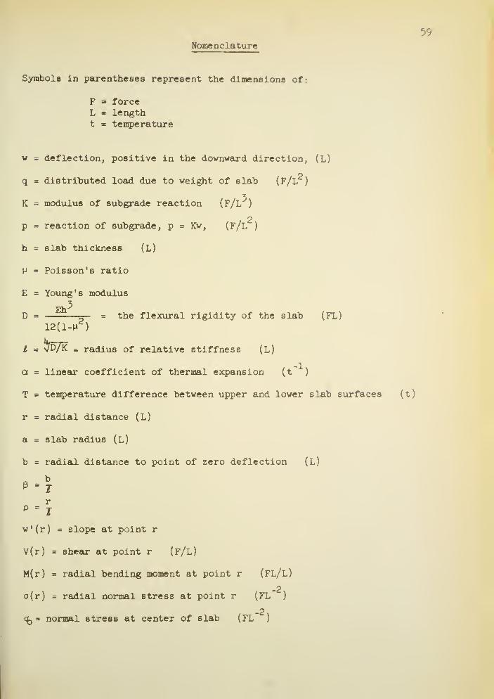
Nomenclature
APPENDIX II
General Solution 6lCalculations of Stress Equations
APPENDIX III
Typical Calculations as Computed by Hand Calculator 67
PageAPPENDIX IV
Flow Diagram of Main Program 71
APPENDIX V
Flow Diagram of Ber X 7^
Flow Diagram of Bei X 11Flow Diagram of Ber' X JkFlow Diagram of Bei ' X 75
VITA 76
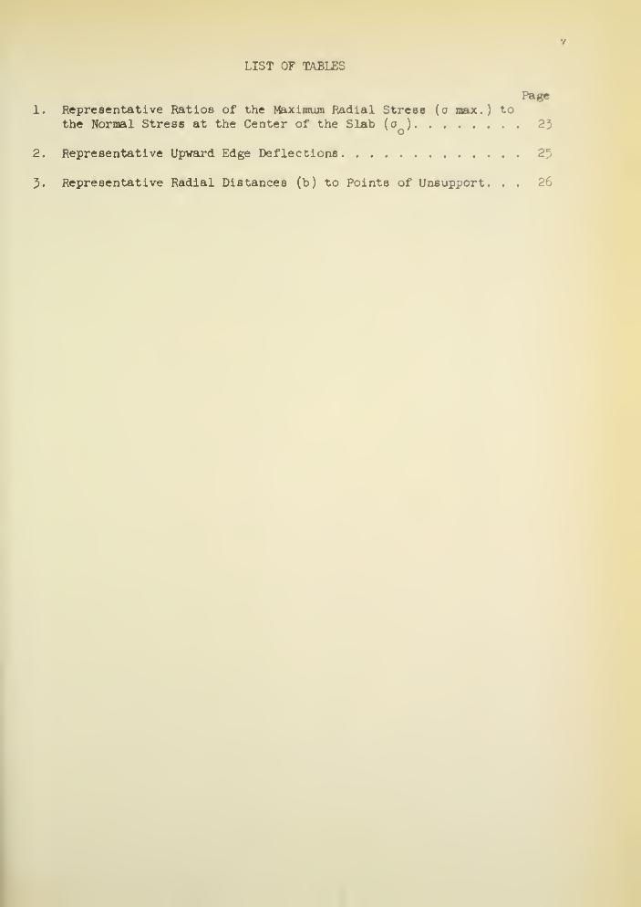
LIST OF TABLES
Page1. Representative Ratios of the Maximum Radial Stress (o max.) to
the Normal Stress at the Center of the Slab (o ) 23v o'
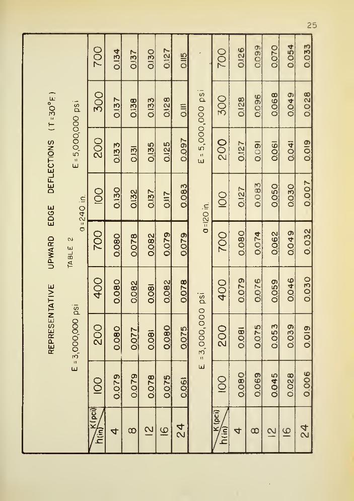
2. Representative Upward Edge Deflections 25
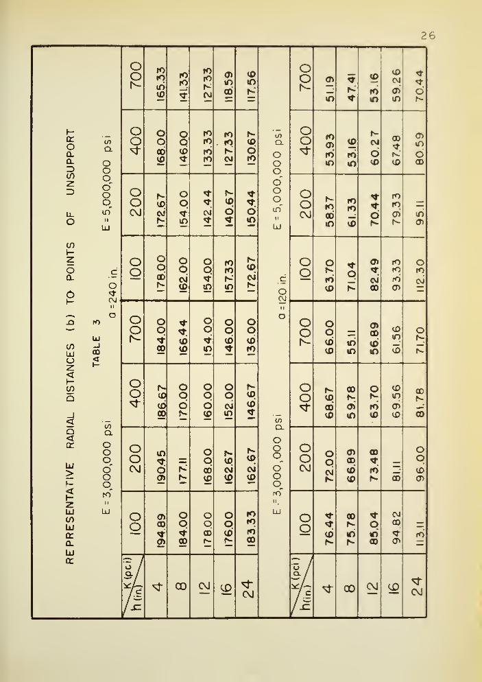
5. Representative Radial Distances (b) to Points of Unsupport. . . 26
vl
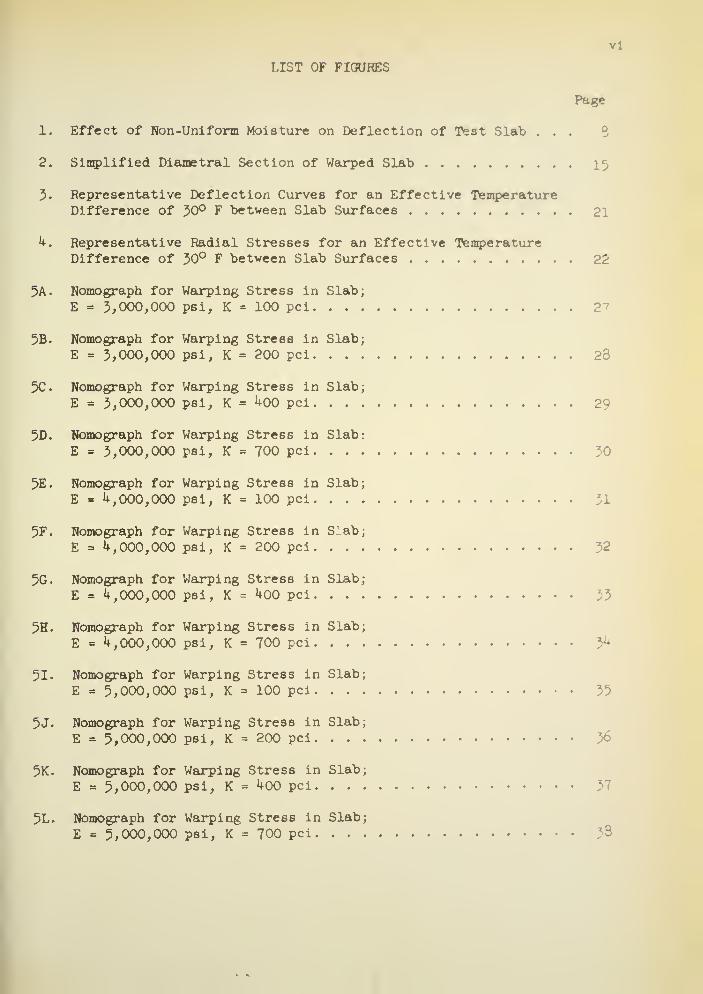
LIST OF FIGURES
Page
1. Effect of Non-Uniform Moisture on Deflection of Test Slab . . .
2. Simplified Diametral Section of Warped Slab 15
3. Representative Deflection Curves for an Effective TemperatureDifference of 30° F between Slab Surfaces 21
h. Representative Radial Stresses for an Effective TemperatureDifference of 30° F between Slab Surfaces 22
5A. Nomograph for Warping Stress in Slab;
E = 3/000,000 psi, K = 100 pci 27
5B. Nomograph for Warping Stress in Slab;
E = 3,000,000 psi, K = 200 pci 28
5C. Nomograph for Warping Stress in Slab;
E = 3,000,000 psi, K = ^00 pci 29
5D. Nomograph for Warping Stress in Slab:
E = 3,000,000 psi, K = 700 pci
5E. Nomograph for Warping Stress in Slab;
E = ^,000,000 psi, K = 100 pci
5F. Nomograph for Warping Stress in Slab;
E - k, 000,000 psi, K = 200 pci
5G. Nomograph for Warping Stress in Slab;
E = k, 000, 000 psi, K = J+00 pci 33
5H. Nomograph for Warping Stress in Slab;
E = k, 000,000 psi, K = 700 pci
51. Nomograph for Warping Stress in Slab;
E = 5,000,000 psi, K = 100 pci
5J. Nomograph for Warping Stress in Slab;
E » 5,000,000 psi, K = 200 pci
5K. Nomograph for Warping Stress in Slab;
E = 5,000,000 psi, K = ^00 pci
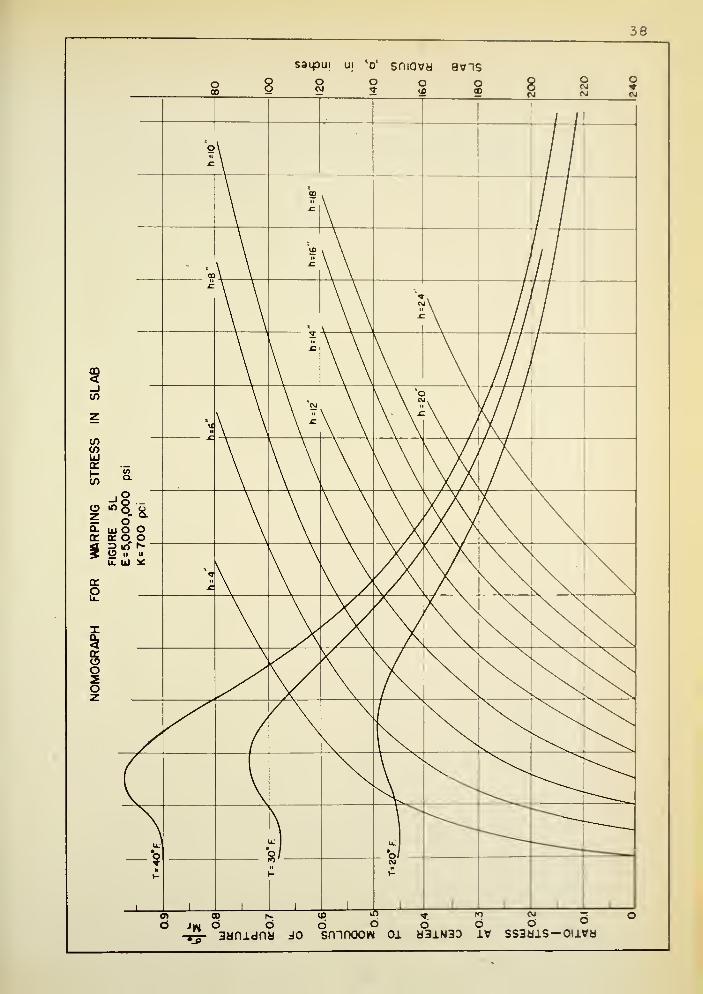
5L. Nomograph for Warping Stress in Slab;
E = 5,000,000 psi, K = 700 pci 38

vil
Page
6. Relationship between Modulus of Elasticity and Modulus ofRupture 39
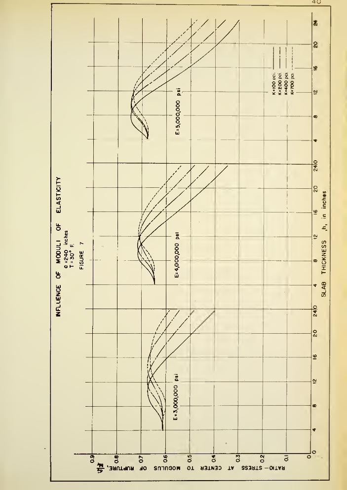
7. Influence of Moduli of Elasticity
8. Influence of Varying Effective Temperature Differences kl
9. Ratio of Normal Stress at Center of Circular Slab to NormalStress at Center of Long and Broad Slab for Conditions ofComplete Support U3
10. Comparison between Observed and Computed Deflections - Hatt . . U5
11. Comparison between Observed and Computed Deflections - PortlandCement Association ^7
12. Shrinkage vs. Water Content for Concrete Masonry Units 50
13. Flow Diagram of Main Program
l^A. Flow Diagram of Ber X 72
l^B. Flow Diagram of Bei X
l^C. Flow Diagram of Ber' X
ikB. Flow Diagram of Bel' X

V. .
ABSTRACT
Harr, Milton Edward. Ph. D., Purdue University, June 1958.
"Warping Stresses and Deflections in Concrete Slabs." Major Professor:
G. A. Leonards.
A theory has been developed whereby the stresses, deflections, and
degree of support of concrete slabs on ground, subject to ambient tempera-
ture and moisture gradients, can be computed for finite slab sizes.
Solutions to the resulting equations were programmed for the Datat
•
2C4 digital computer at Purdue University. As a part of the solution,
subroutines were developed for the Ber and Bei functions and their first
derivatives.
Nomographs are presented which give ratios of the critical stress to
the modulus of rupture for a wide range of environmental gradients , and
for various combinations of slab sizes and thicknesses. For slab size6
and equivalent temperature gradients that comply with Westergaard 's
assumptions of a fully supported slab, computed stresses and deflections
check those obtained by the Westergaard theory. However, the maximum
gradients for which the Westergaard theory was found to be applicable are
very much lower than those commonly encountered in practice. The new
theory is capable of accounting for the more critical conditions, which
develop when the slab is only partially supported.
Conclusive evidence regarding the reliability of the derived theory
is not available at this time. However, comparisons between computed
deflections and available measured deflections strongly indicate that the
theory is applicable to concrete highway pavements not subject to super-
imposed traffic loads
.

Although many factors, such as aggregates, water-cement ratios,
curing, carbonation, etc., affect the moisture content -volume change
relationship, the available data indicate that combined temperature and
moisture gradients encountered in practice are capable of producing
tensile stresses which exceed the modulus of rupture of concrete. In
the critical shrinkage range, a moisture gradient of one percent can
cause warping equivalent to a 20 degree F. difference in temperature
between 6lab surfaces. Accordingly, cracking may occur at small
temperature gradients if moisture differences between slab surfaces are
only a few percent.
The concepts developed in this study can provide the basis for the
solution of a number of problems involving warping of slabs; for example,
"slab on ground" construction for homes, icing of lakes, and the like.

INTRODUCTION
As of the end of the 1955 calendar year, approximately 100,000
miles of Portland cement concrete highways were in use in the United
States. In 1955, alone, almost 2100 miles of this type of surface
were constructed (^6)*. According to F. B. Farrel and H. R. Patrick (9),
expenditures for all types of surfacing on primary and secondary roads
have comprised about ^0 percent of the construction funds for highways
as compared to about 25 percent, each, for grading and structures.
These percentages are based on an estimate of total construction expen-
ditures from 191^ to 1952 in relation to prevailing prices of January 1,
1953.
The average expected service life to zero salvage for concrete
pavements has decreased from 27 years in 1911* to 25 years in 1955;
whereas, the service life of concrete highway structures has increased
from ^0 years to 52 years in the same period (^,9). In addition, a
great number of concrete pavements are resurfaced each year in an
attempt to halt deterioration and to restore their life. The life of
resurfacing is itself rather limited by "reflection cracks" from the
resurfaced slab (^, 53). Usually, such cracks appear in the resurfacing
during the first few years of service. According to Bone, Crump, and
Roggeveen (^ ), "Reflection cracking is a serious problem where
* Figures in parentheses refer to references in the Bibliography.

2
bituminous resurfacings are placed over old cement-concrete pavements.
The cracks detract from the appearance and riding qualities of the
surface and may be expected to shorten the effective life of the
resurfacing . . . there is no sure method of eliminating reflection
cracking. " The initial occurrence of pavement cracks is injurious
not primarily from the standpoint of driving comfort as pointed out
by Cashell and Teske ( 8 ), but rather from the danger of water penetra-
tion with subsequent pumping, loss of subgrade support and increased
pavement deterioration (5*0- That cracks are the result of excessive
tensile stresses in the concrete is well-known. However, the causes
of these excessive stresses have not been properly evaluated, for
obviously less than optimum performance has been obtained from concrete
pavements and the remedial measures designed for them.
In the past, deterioration of unsound concrete was a primary
cause of pavement failures; however, these difficiencies have been
largely eliminated. According to Friberg (ll), sound air entrained
concrete is equal to well over 50-years service in climates common to
the United States. Unsound aggregates have been largely eliminated.
Frost-heaving on concrete roads has been greatly reduced. To be sure,
unsatisfactory materials have been the cause of some pavement replace-
ments, but they appear to be of a localized nature. As reported by
W. van Breeman (6 ), "Almost all of the failures that have occurred
with concrete pavements in New Jersey have been of a structural nature,
as differentiated from failures attributable to weakness or disintegration
of the concrete itself. " This conclusion has also been shown in many

other investigations ( 1, 50, 8, 17, kl, i6 ) . The realization of
a longer service life, therefore, is not blocked by material limitations.
It should be noted that even material failures seem to be peculiarily
oriented near transverse cracks and Joints (1,50). This is due primarily
to the increased exposure of the concrete along these Joints and cracks.
In recent years, application of soil mechanics principles to
pavement design has largely eliminated poor subgrade support as a
primary cause of concrete pavement failures. Frost susceptible soils
have been isolated and effective remedial measures have become common
practice ( k, 26, 55, 55, 52, 51, 20, 17, 7 ). According to Friberg
(11), "Poor subgrades cannot be disregarded as a continuing deteriorating
influence. But, with the exception of localized frost heaves or unusual
disturbance of soil equilibrium, subgrade instability appears to be
serious exclusively at Joints and cracks. Even subgrade pumping, a
major sign of deterioration of the pavement, has not been of consequence
away from Joints [edges] and cracks."
The most common critical conditions in concrete pavements are
reflected by the cracks in existing roads. The occurrence of corner or
diagonal cracks, transverse cracks, and longitudinal cracks have been
recorded in many published surveys of concrete pavements (1, 50, 26, 59,
2, 25, 52, 50 )• In 1952, a crack survey was made under controlled
conditions on the Maryland Test Road (17). The data show a predominance
of transverse cracks. As a matter of fact, recent performance surveys
6how that it is rather unusual to find corner failures, in modern
concrete pavements, of the type analyzed by Westergaard (^7), Teller and
Sutherland (kl) , Spangler (56), and others.
On 900 miles of Louisiana 6-inch thickened pavement with k2 feet
average Joint spacing, Friberg (n) reports 86 percent of all cracks
were transverse. Corner cracks averaged less than one per mile. On
the Maryland Test Road (17), sections 1, 2, and 3, 98 percent of the
cracks were transverse cracks. In 1°A8, H. Allen and F. H. Jackaon
reported on a survey of the concrete pavement on the German autobahn
(20), "Transverse cracking was common and was not confined to any
particular part of the system. There seemed to be no relation between
transverse cracking, terrain or soil conditions." Similar data for
continuously reinforced concrete pavements have also been reported ( 8 ).
Longitudinal center cracks, common in pavements prior to 1925,
have been almost completely eliminated by center joint construction.
However, as noted by Friberg (ll), "Longitudinal cracks near the
outside pavement edge, extending for a short distance from transverse
joints, sometimes referred to as "infiltration cracks", appear to be
increasingly common ... on Road Test One-MD, section U on pumping
soil, subjected to heavy tandem-axle loading, a different type of
longitudinal cracking occurred. Here 11 percent of the cracks were
longitudinal and all originated at transverse Joints k to 5 feet
from the edge, and extended progressively further away, finally meeting
at mid-length of the ^0 ft. slabs. This longitudinal cracking is an
indication of critical transverse load stresses near transverse joints
in connection with loss of subgrade support.
"
The results of many investigations have shown that the critical
stresses in a concrete pavement slab, which are mirrored by structural
cracks of specific orientation, are primarily due to the combined
effects of traffic loads, pavement warping, and pavement pumping
(20, 11, 10, 17, kl, h& ). To use concrete pavements with maximum
economy and efficiency, it is necessary to predict, as accurately as
possible, the character and magnitude of the stresses induced in a
slab by continually changing environment and by the traffic loads to
which it is subsequently subjected.
Concrete expands or contracts as its temperature and moisture
content increases or decreases. Concrete pavements are exposed to the
elements and, consequently, are subject to diurnal and seasonal changes
in length. In addition, temperature and moisture differences between
the tops and bottoms of slabs result in their tendency to warp.
In the past, investigators have examined the effect of the position
and magnitude of the wheel loads on a pavement slab C*7,36), of the
presence of one wheel load near to another (37), of impact (5 ), and of
traffic frequency (38,31). All of these analyses have been based on
the assumption that the slab maintains contact with its support at all
points and at all times. Recent experimental studies (12), have clearly
demonstrated that this assumption may be seriously in error. Accordingly,
improved analytical procedures are predicated on the development of a
theory that allows for the possibility that warping may result in the
slab's being only partially supported when it receives traffic loads.
It is the object of this thesis to obtain by analytical means the
deflections, stresses, and degree of support of concrete slabs subject
to environmental temperature and moisture gradients
.
REVIEW OF LITERATURE
Part I
Warping of Concrete Pavements
In I879, Bauschinger ( 5 ) pioneered investigations into the
volume changes of Portland cement concrete induced by variations
of temperature and moisture. Following Bauschinger, many investigators
have measured the effect of a number of factors on volume changes in
concrete, among which are the effects of age of specimen, quality of
cement, kind of aggregate, richness of mix, duration of exposure, and
the like. An excellent discussion and bibliography of these early
investigations is given by Hatt (±k) .
With the advent of concrete pavements, highway engineers soon
became aware of the detrimental effects of volume changes. As early
as 1910, the Office of Public Roads (15) conducted a series of
laboratory and field tests to study the expansion and contraction of
concrete pavements. In 1922, tests conducted on the Bates Experimental
Road (29) led to the discovery that temperature differences between
pavement surfaces result in considerable warping of the slab. As
pointed out by Teller and Sutherland (!+l), "The early investigations
were of value, first, for the information that they developed, and
second, because each one served to arouse more wide -spread interest
in the subject among highway engineers."
In 1925, Hatt (ik) reported warping could be induced by a
corresponding moisture difference between the surfaces of the slab.
Hatt's studies are of special interest since they apparently represent
7
the only published data on the effects of moisture on concrete slabs
under controlled conditions. Hatt's observations were based on studies
of a concrete slab, 7 inches thick, 18 feet wide, and 25 feet long
(with a longitudinal doweled center Joint) on a 4 -inch coarse gravel
base. The slab wa6 covered and housed to control the distribution of
moisture and temperature. Among Hatt's conclusions is the following:
Concrete road slabs warp upward at the corners and atthe edges when the surface becomes dry, and also when thebottom absorbs moisture from the subgrade. Drying the topsurface of the slab under observation deflected the cornersupward 0.02 inches. When the bottom of the slab was saturatedfrom a water filled subgrade the upward corner deflectionreached 0.20 inches. This curling upward of the corners ofthe road slab presents a cantilever beam to the load of apassing truck. The results of the tests indicate the presenceof an initial stress in the surface of the road slab arisingfrom the warping.
Hatt recognized that portions of the slab could be unsupported.
In fact, in reference to some load tests, he states, "As the warping
of the slab increased, the point of support must have moved in,
increasing the deflection." Figure 1 is reproduced from Hatt's paper.
The curves clearly illustrate the degree of unsupport and the influence
of moisture. It should also be noted that the maximum downward deflec-
tion does not occur at the center of the slab. All measurements of
surface deformations of the slab were the result of moisture differences
alone since observations were taken at times when the temperatures were
constant throughout the slab.
Beginning in 1930 and continuing to their final report in 19*0,
the Public Road Administration, under the direction of L. W. Teller and
E. C. Sutherland (hi), conducted several extensive investigations to

8
III V-
rr <z> CD 1-
\- <</> ICE
o (/)£^
*5JC UJO t-
UJ
z 7o o*£ »-
U-ooUJ_1u.
H UJo QUJll
ll ^UJ o
UJ>or
o_ CO ro cl-
evis dO U31N3D
8 CO CD ^ CVJ o R 8 ao o b 6 o o o o o
S3HDNI Nl N0liD3"ld3a
develop a better understanding of the structural action of concrete
pavement slabs. The significant observations and conclusions
pertinent to the present study are as follows:
1) Warping has two important effects on the structuralaction of a pavement slab. In the first place, the distortionthat occurs alters the conditions of subgrade support and thusaffects the magnitude of the stress that will be produced by agiven wheel load. In the second place, because of the weightof the slab, the warping in itself causes important stresseswithin the slab structure. Both of these actions place limita-tions on the maximum wheel load that may be carried by thepavement, and, for this reason, any information concerningthem is of value.
2) In the early morning and in the afternoon when the maximumtemperature differentials occur, there is approximately astraight -line gradient in temperature between upper and lowersurfaces of the concrete. These are the two times of the daythat are most important in the determination of stress causedby warping. [Due to the lack of instrumentation it was notpossible to determine moisture gradients. Figure 28 of the
report indicates that there was relatively little differencein upward deflection between the free edge and the longitudinalJoint, and the free end and the transverse Joint.]
3) A comparison of the relative magnitudes of the stressescreated by warping at the center of the slab [10 x 20 feet] in
the transverse and longitudinal directions shows that the
stress in the direction of the 10 foot dimension is approximatelyone -third of that in the 20 foot dimension.
k) The actual temperature differential between upper and lower
surfaces of the slab is always greater for the thicker slab.
[The iwyimim positive temperature gradient (bottom temperature
greater than top) at the test site (Arlington, Virginia) was
approximately 1-1/2 degrees per inch. No information as to
moisture gradients was noted.
]
In summarizing their data, the authors state:
The data that have Just been presented clearly indicate
that the stresses arising from restrained temperature warping
equal in importance those caused by the heaviest wheel loads.
The stresses from this cause are actually large enough to cause
failure in concrete of low flexural strength, and since the
direction of the stresses is such that they become added to the
critical stresses caused by wheel loads, there is little doubt
but that warping stress is primarily responsible for much of the
cracking in concrete pavements.

10
More recent tests (1952), conducted in southern Maryland as a
part of "Road Test One-MD" ( 17), indicate that for corner loading the
stresses and deflections for severe downward-warped conditions are
only approximately one -third those for the critical upvard-warped
conditions. For the free-edge loading the effect of temperature
warping, although appreciable, was not as pronounced as for the case
of the corner loading.
In 19^, the California Division of Highways, reflecting the
concern of highway engineers throughout the United States, began
extensive field and laboratory studies to determine the cause of distress
at the joints of concrete pavements. The results of this study were
reported by F. N. Hveem (l8). Hveem's comments on subgrade support
follows
:
Engineers have paid much attention to subgrade support forconcrete pavements at or near the planned Joints in the pavement,but if it is recognized that for a considerable portion of timerigid pavements do not rest on the subgrade for several feeteither side of the joint, it seems pertinent to ask whetherWestergaard's K is a significant index for the design for suchpavements
.
In a recent paper, Hveem (Figure 38 of reference 19 ) presents a
view through a core hole in the pavement slab which shows approximately
l/k inch clearance between the slab bottom and the subbase. The slab
also shows a crack in this area. In reference to this illustration,
Hveem states, "The existence of this space 'sets the stage' for pumping.
There is reason to believe that the so-called pumping action could
never start if the slab were firmly in contact with the subgrade at all
times.
"

11Part II
Theories of Stresses and Deflections in Concrete Roads
Caused by Variations of T mperature
In the past, engineers have recognized the possibility of the loss
of subgrade support at the corner of a slab resulting from moisture and
temperature differentials. Older (29), in 192U, derived an equation for
the required thickness of a concrete slab assuming that the corner was
entirely unsupported. This "corner formula" was subsequently refined by
Westergaard (1*9), Kelley (23), Spangler (56), Bradbury (5 ), and Pickett
(31). However, as previously noted, there are few breaks of this type
currently found in highway pavements. According to Sutherland (ko)
,
this is not only true of modern pavements but also of older pavements
that are still in use.
In 1925, through the initiative of A. T. Goldbeck, then Chief of
the Division of Tests in the Bureau of Public Roads, H. M. Westergaard
was engaged to make theoretical studies of the structural action of
pavements due to various types of loading (U7). In 1927, Dr. Westergaard
supplemented his earlier work by analyzing the stresses and deflections
induced in slabs by temperature variations.
To obtain solutions, Westergaard made use of the following
simplifying assumptions:
1) The slab is a homogeneous, isotropic, elastic solid of uniformthickness.
2) The slab is of infinite length and finite width.
3) The subgrade provides full and continuous support to the
pavement at all points and all times.

12
M The reaction of the subgrade is vertical and proportional tothe deflections of the slab.
5) The temperature gradient increases linearly with the depth ofthe slab and remains constant on all planes parallel to theupper and lower slab surfaces.
In reference to Westergaard's analysis, Sutherland (*K)), in 1956,
writes
:
At the time that this analysis was made it was not realizedthat the temperature differentials that develop in concretepavements are as large as they are. After seeing some of thetemperature differential data obtained in the Arlington investi-gation (25), Mr. Westergaard expressed the opinion that hisanalysis might not be applicable for temperature differentialsof these magnitudes.
In 19^0, J. Thomlinson (*0), modified Westergaard's approach by
assuming a simple harmonic temperature variation at the top surface of
the slab, rather than a uniform temperature gradient in the slab. Applying
the laws of heat flow, Thomlinson arrived at a curved temperature
gradient throughthe depth of the slab which corresponds fairly closely
with the cyclic daily observations of Teller and Sutherland C+l), and
Lang(2U). However, as was previously noted, Teller and Sutherland
concluded that although the curved gradient represents the more usual
distribution of temperature, the straight line gradient defines the
most critical stress condition caused by warping. Thus, it is not
surprising that numerical values of the stresses computed by Thomlinson 's
analysis are less than those of Westergaard.
The analyses of Westergaard and Thomlinson represent the two major
theories that have been developed for the calculation of warping
stresses in concrete pavements due to temperature gradients. Both
theories are predicated on full and intimate subgrade support. As

13
recent field studies have shown that this assumption may be seriously
in error, the reliability of the stresses computed on this basis is
open to question.
In spite of this fact, Westergaard's approach still remains an
outstanding contribution to the problem of warping stresses in concrete
pavements. Further analytical work need only be concerned with
modifications of the simplifying assumptions to conform more closely to
observed behavior. The fulfillment of this objective is the primary
purpose of this thesis.
Ik
THEORY
Assumptions
1.) Slab is of circular shape, homogeneous and isotropic with a
free edge boundary.
2.) Slab is supported on a homogeneous foundation.
3.) Reaction between slab and support at any point of contact is
proportional to the deflection at that point.
k
.
) Slab obeys Hooke ' s law
.
5.) Deflections of the slab are small in comparison with its
thickness
.
6.) Only external forces acting on the slab are thoBe due to
gravity.
7.) Slab is subject to ambient changes in temperature and/or
moisture content which vary linearly with the depth of the
6lab but are constant on all planes parallel to the upper and
lower slab surfaces.
Formulation of Problem
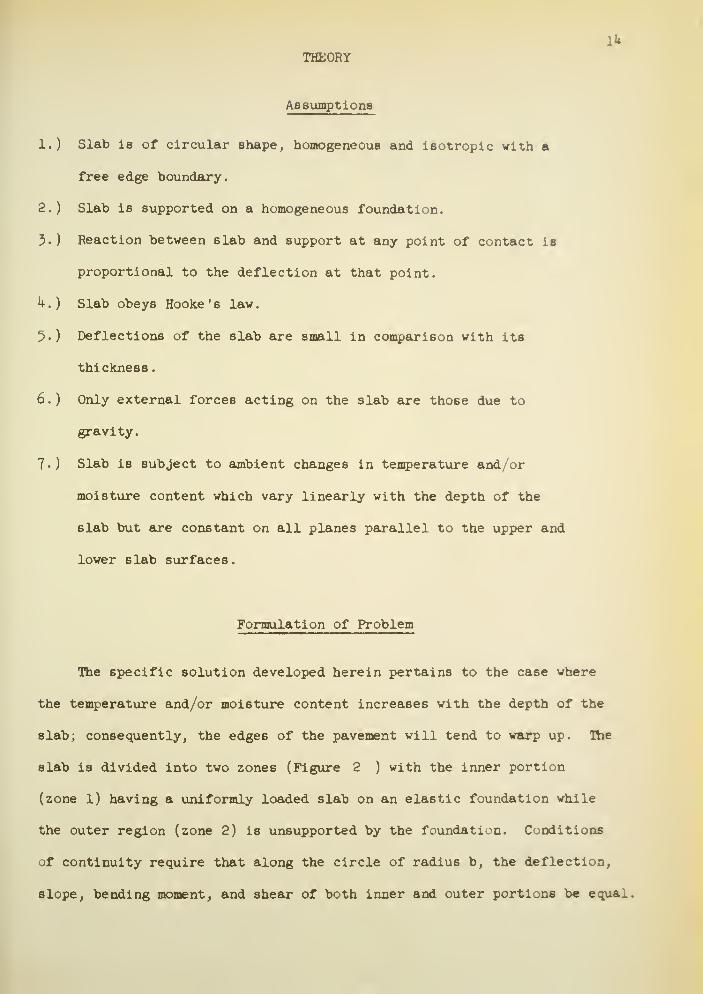
The specific solution developed herein pertains to the case where
the temperature and/or moisture content increases with the depth of the
slab; consequently, the edges of the pavement will tend to warp up. The
slab is divided into two zones (Figure 2 ) with the inner portion
(zone 1) having a uniformly loaded slab on an elastic foundation while
the outer region (zone 2) is unsupported by the foundation. Conditions
of continuity require that along the circle of radius b, the deflection,
slope, bending moment, and shear of both inner and outer portions be equal.


16
As the loading and reactive forces are symmetrically distributed
about an axis perpendicular to the slab through its center, both the
slope and the shear at the center of the slab must be zer
The assumptions, boundary conditions, and symmetry may be
summarized as follows (see nomenclature in Appendix I):
a) V(o) =
b ) vx
(0) =
c > wx(b) =
d • V2(a) =
e 1 Mg(a) =
f 1 v2(b) =
g » "^(b) = w2'(b)
h Mx(b) = Mg (b)
i, vx(b) = v
2(b)
Solution of Problem
Applying the conditions listed above to the governing differential
equations, the following equations for stresses and deflections in the
slab are obtained (see Appendix II for derivation):
For 0<r<b or < p < p,
a =
(l-n)Z '(p)
^- [ -S* {C,[Z2 (p)
-±] - C
2[Z (p) +
2(1-m2
) Kl2 X 2 p 2 X
Eh q(1-m)Z
2'(p)
])
+ a ( 1 + n ) i]
wx(p) = i (1 + C
1Z1(p) + C
2Z2 (p)}
(19)
(9)

17
For b < r < a,
2
r-^ tC
6(,-l)(-J--J>
Sg^, in i - ligji (.Z.r2)] (l8)
2 „ 2U
w2(r) = C
5C6
In r + Cf + CQr In r ^ (5)
where
i + c2z2 (p)
ci
=TTBl
—
( 10 >
C,(n-1) 2o ~- /, -v qa rt/..^, », . , ,,,„», . „*,..,i T^ + 2C
?(l+n) - 3g- [4(n+l)ln a + On)] + a(l+u) ± = (13)
c5.c
6i„b,c/-3^i.^,o (iM
C 2. 'S
4 +^ - %r < 21n b + 1} +i$d - kJ t c
izi'(P) + c
2z2 -(e)] = o (15)
C P P
4 (n-U + 2c7(i+n) - ^ [2(i+m) m b (>n)] 3^ (>m)
(l-n)Z/(e) (l-n)Z '(0)
- -\ (c1[z
2(p) J:
] - CglZ^ft) f ])-0 (16)
Z «(p) - Z.(e)[a2-b
2]
*
c2
= - l-2- 1 ?££). (17)
z2(p)z
2'(p) + z
1-(3)z
10)
An examination of these equations shows that a prohibitive amount of
work would be required to eliminate the constants and then obtain an

18explicit expression for either the stresses or deflections in terms of
the slab parameters. In the early stages of this study, form Bheets
were prepared and used to simplify the computations. Appendix III
contains a typical set of calculations as computed by hand calculator.
To evaluate the effects of various combinations of factors that are of
interest, it was estimated that these calculations would have to be
repeated several hundred times. Thus, it was decided that a high-
speed calculator was essential to obtain the desired information
within a reasonable period of time.
Digital Computer
The problem was programmed for the Datatron 20^ digital computer
at Purdue University. As a part of the solution, subroutines were
developed for the Ber (p) and Bei (p) functions and their first
derivatives (see Appendix V).
The main program (see Appendix IV ) was written with b, the radial
distance to the point of zero deflection, as the independent variable;
and T, the effective temperature difference between the slab surfaces,
as the dependent variable.
Initially, the program was set up such that by introducing a set
of parameters (a, K, E, h, etc.), the computer would solve for T
corresponding to the condition b = a, and then, print out the stresses
and deflections at equal radial increments across the slab. Repeating
the cycle with decrements in b, the stresses and deflections were com-
puted for a range of temperature differentials
.
It soon became apparent that it would be more advantageous if T
wa6 the independent variable. An examination of the equations showed

that it would be impractical to solve for b as a function of T.
However, by virtue of the speed of the computer, a modification was
written which effectively transformed the initial program to one with
T as the independent variable. If the stresses and deflections were
desired for a temperature differential of 30 , the computer would
choose b = a and solve for T as before. The resulting T would then
be compared with 30 . If the T value was less than 30 , the computer
would select a lower value of b and solve for the corresponding T.
The cycle would repeat until a T greater than 30 resulted. The computer
would then back-step a fraction of the decrement and recycle. By
repeating the procedure, T could be obtained to any degree of precision.
Having the corresponding b value, the stresses and deflections were
readily computed. On the average, ^5 seconds were required to obtain b
for any T; during this time, the computer recycled approximately 15 times,

20RESULTS
The derived equations were solved for deflections and (normal)
radial stresses for combinations of the following:*
E = 3 X 10 , h x 106
, 5 x 10⁶
psl
a = 80", 120", l60", 200", 220", 2Uo"
h = V, 6", 8", 10", 12", Ik", 16", 18", 20", 2U"
K = 100, 200, 400, 700 pci
T = 20°, 30°, k0° F
a = 6 x 10" inches per inch per F
n = 0.15
Typical deflection curves for an effective temperature difference
between slab surfaces of 30 F are shown in Figure 3- Corresponding
radial stresses as a function of the radial distance from the center of
the slab are shown in Figure k.
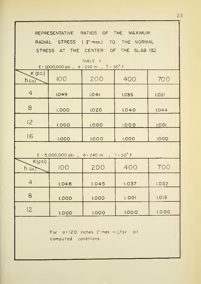
Ratios of the maximum radial stress (o max. ) to the stress at the
center of the slab (a ) were computed for combinations of the following
parameters
:
E = 3 x 10 , 5 x 10 psi
a = 120", 2^0"
K = 100, 200, 400, 700 pci
h = k", 8", 12", 16", 2k"
The results are presented in Table 1, which shows that for a = 2^0"
there is little loss in precision by assuming the central 6tress equivalent
to the maximum stress; for a = 120", the central stress is the maximum. As
*See page 59 for list of symbols

21
UJ
CO
8
MUJ CO
U_U-
,UJ CD
z
trou_
CO
zUJUJ
I-UJCO
CO u.-
ooto
cc
O
h^
U-O
UJ
UJu- trUJ UJ
u.
Q
EB
S§co p:UJ UJcc '
Q_UJ UJCC
oiI
fi£ l£ £ e r
240
200
lt.fi
120
Mi)
.Hi
0'
240
200
160
120
80
40
0'
radial
distance
,r,
in
inches
- - ]—
V)Q.
O//
0.
8« .
o" a-.S8§•1 £ J
8 o°. ou-> i-- \J Q. O »
ro r- tvj
11 ii ii
uj *:
// 1
UJ * D As .
/ / /
4^^
-tt>
i
VjC -e 4/-=
*£
/to
, 1 /or
CD
nO.
oO —
1.8in <m
y/\CL
EZ
3,000,00<
200
pci
240
in.
i it
Ui * UJ » O
^1 —
II
- 1 Vc\il p
.cj J
j
<»
s
M
nCL
o8 «Q. Q.o
//MQ.
OO°. E
O '
r//
/
y 1 ro o-r<T I'-
5/
'/
og'o«« S ~
' M • ii
UJ *ll ii
UJ * O
y
^^-^\^ /I< r cu <
2 CD <
*-> c
Sc
r c
iipui
\c
3 C
SN(
r °° *• * £) c
> = Q O Q O w<
)llD3"ld30
8 g

22
REPRESENTATIVE
RADIAL
STRESSES
FOR
AN
EFFECTIVE
TEMPERATURE
DIFFERENCE
OF
30°
F
BETWEEN
SLAB
SURFACES
e>1
II \
1 ' - 1
JO
90
60
30
d
240
210
180
150
120
90
60
30
240
2i0
180
130
120
90
M
30
1
RADIAL
DISTANCE
,
r,
in
inches
1 \cm\
II
X.
\L N
*\ \
•
V —
Vt
Q. ^- \. \
ooo.ooc
pci
>Oin.>v
1
oo _° HO °-.SgooO. o Vn N tu
ui X. o
1
m n biu it ||
Ul J£ O1
el
\ J= \ J\ \
\/ N\
* / " \/
c ^X.
\ ^ \
or
o I
u. \
-
cm \M v \
1
E=
5,000,000
psi ^""^-^
00,000
psi
pci
/ NSv\
OQ.
C2 6 pOo *CM CMit ii
X o
cK
ll
>. o ») CM CM
1 * O
1
e"vlc 1
sz
'5
cC
s
o.
oo _o ->
o8SIO N"M 1| II
O — c
8 go»HI If O .
i t xl\
S ° S cto CO O cin » * -
jSd
J Q o O cj <J UJ CD) CM _
ui avns jo BDvjans &3c
O ZCM <r
po c*
IdO J.V SS3U1S
2 o °
IVOWel
23
REPRESENTATIVE RATIOS OF THE MAXIMUM
RADIAL STRESS ( fmox.) TO THE NORMAL
STRESS AT THE CENTER OF THE SLAB ((E)
TABLE 1
E = 3,000,000 psi , a =240 in , T = 30° F.
^\K(pci)h(lnT\^ 100 200 400 700
4 1.049 1.041 1.035 1.031
8 1.000 1.020 1.040 1.044
12 1.000 1.000 1.000 1.001
161.000 1.00 1.000 1.000
E = 5,000,000 psi , a = 240 in. , T = 30° F
^K(pci)h (inT\^ 100 200 400 700
4 1.04 8 1.045 1.037 1.032
8 1.000 1.000 1.001 1.013
121.000 1.000 1.000 1.000
For a- 120 inches (T max = :'
c for all
computed conditions
2k
several minutes of computer time were required to calculate the maxlamn
stress, whereas the time required to obtain the stress at the center
could be measured in milliseconds, this latter stress was used in lieu
of the maximum stress in the analyses to follow. In no case is the
error greater than %.
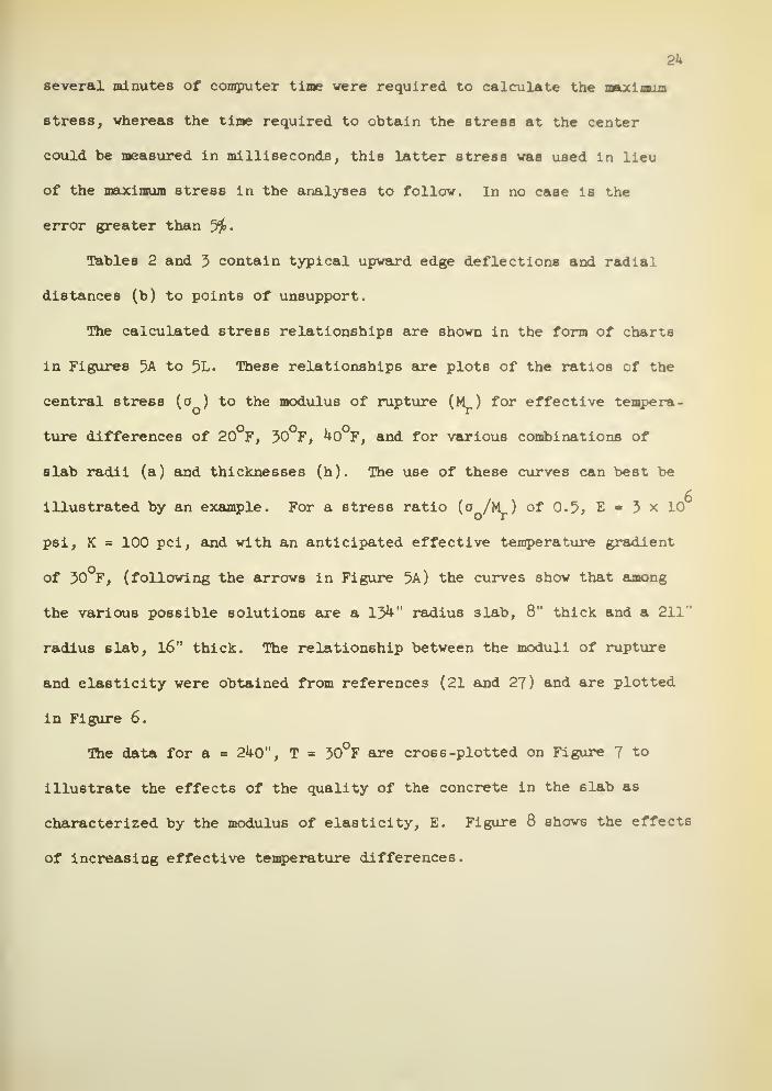
Tables 2 and 3 contain typical upward edge deflections and radial
distances (b) to points of unsupport.
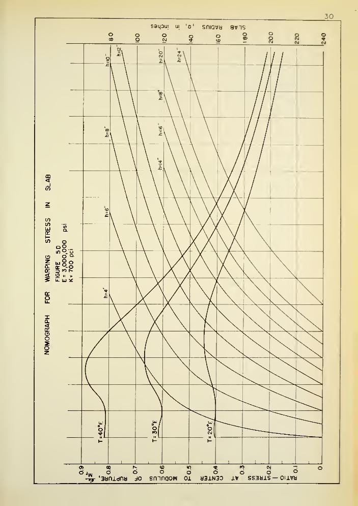
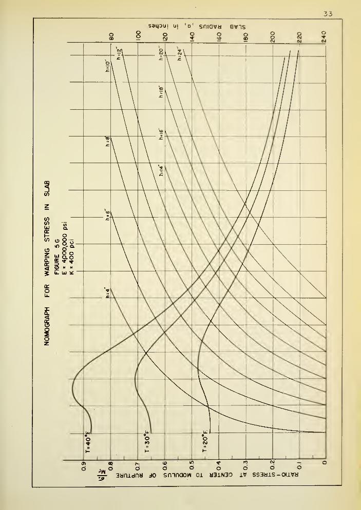
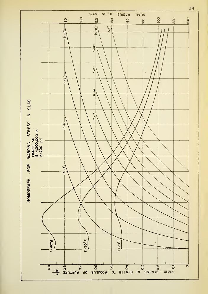
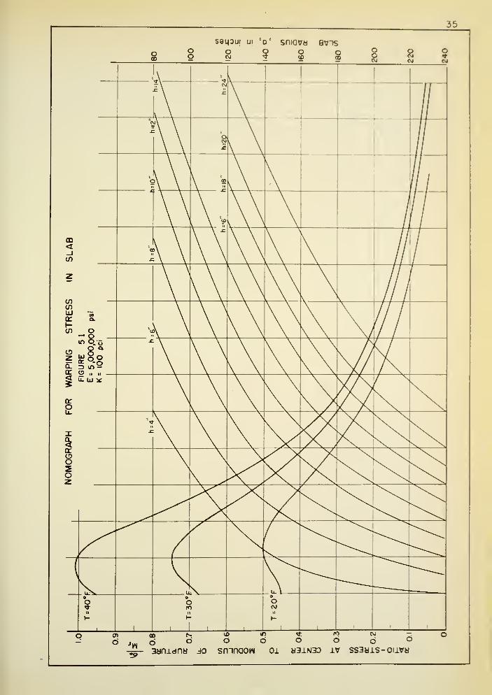
The calculated stress relationships are shown in the form of charts
in Figures 5A to 5L. These relationships are plots of the ratios of the
central stress (o ) to the modulus of rupture (M ) for effective tempera-
ture differences of 20°F, 30°F, ^0°F, and for various combinations of
slab radii (a) and thicknesses (h). The use of these curves can best be
illustrated by an example. For a stress ratio (o /M ) of 0.5, E 3 x 10
psi, K = 100 pel, and with an anticipated effective temperature gradient
of 30 F, (following the arrows in Figure 5A) the curves show that among
the various possible solutions are a 131*-" radius slab, 8" thick and a 211"
radius slab, l6" thick. The relationship between the moduli of rupture
and elasticity were obtained from references (21 and 27) and are plotted
in Figure 6.
The data for a = 2^0", T = 30°F are cross -plotted on Figure 7 to
illustrate the effects of the quality of the concrete in the slab as
characterized by the modulus of elasticity, E. Figure 8 shows the effects
of increasing effective temperature differences.
25
O t r^- o N O CD onCD
oin
roroo ro ro ro CM in o CM O o O O
r>- 6 d d d o r- d d d d O
Llooro
N- 00 ro 00 CL o 00CDCD
GOCD
0) 00CM
o toQ.
ro ro ro CM o o CM O O o Oii O O d d d o o
orO d d d d d
1- o""""'
'
oo"
oo
coZO
oo,IDII
oo(\J
roro
d!2
d
inro
d
mCM
d
CD
od
CD
in
LU
OoCvJ
CM
dod
(DOd
od
CD
Od
o UJ
_)U.LUQ
doo
oro
COro ro N
ro00O O
OCM
roGO
OotoO
oroO
oo
UJ O d O d o d g d d d d do t OoUJ
CO1
1
COII
o o o 00 CM CD CDo o o £ CM O) CM
roQCC<
CM
LUo 00
or-o
00o O r-
O o 00o
NO
CDO
<*
o O
COd d o d d d d d d d
QlO £
o o CM CM CO o o> CD CD CD oUJ o CD 00 GO 00 n O r- N- in ^ ro
>si- O O O o o • — o o o o O
h- d d d d o CL d o d d d
2 CL oo
LUCOUJa:Q_
O8o'
ooCO
o00o
r>-
oCD
oo00o
mo
ooo
OOOJ
00o
inNO
romO
CDrOO
CD
oUJor
oCO d d d d d o
ro"
d d d d dIffII
ii
LU LU
o cd OD mlo o o
00CDCD
m COCM
CDo
o o o o O o o o O o O od d d d d d d d d d
'5 /Q. / w /
a. /
7c si- oo C\J COsf(NJ
*/? sl- 00 CvJ (0CvJ
/jC Ac
26
OO1^-
rorO
inCO
roIO
rorO
CM
0)mCO
COm
OO <J>
in
CO
rom
COCVJ
cnm
70.44
h- o O O ro ro h- t/>O
ro0)
ro"
m
r--CO<*
CD
encco0.a.
10 o O o ro ro co Q. o CO CVI
Q.
Osj- CO
COco
5roro
r»"
CVJ
dro O
o<fr ro
in
dCO
oOD
idco
ID
Ooo"o
ooo<d
in
Ul
o ^ o <fr r^ * od
ro
LL
O
CO
z
q.inii
UJ
oCO
CO0J
oCO
cvi
<*
CO
d dm
oCvJ
r*-
roCOm
roro
co
ro
en mcn
o oo O O ro r*-
cp o oq
en rO Oo c o o O ro o r«- * ro roQ.
dO
00 cvi
co<*m in
cvi cOCM
roco
cvi
COrOcn
c\j
n ii
.Oo
fO o o * O O O O o o cnCO
"—
'
o o <frO O O o O — CD O
UJ_103
1^-<fr CO * cb CO r^ cb ih cb
lO N;
COUJ
CD CO l£> 5 ro CO m m CD r-
o <1-
<co
oo N O o O r*- o h- 00 O CO X
Q CO O o q cp o cp r- r- in
CO d d cvi cbsj- oo' cn ro cn
sftoQ.
CO N CO in ^Q.
CO m co CO C0
Q< oor
UJ>
Ooo
oo ^m
oo co
r^CO
o oo o
qen00
CO OO
o CO d s CO cvi cvi d CJcvi co ro
—™CD
o o> N CO CO co or«- CO r» CO cn
1— o ^^ oro rO
2 ii
UJCOUJ
UJ o 0) o o O ro UJ oo
* 00 * CVI
o oo o O O ro"fr K o CO ~
or <f <t 00 CO ro cb m m <fr mi
Q. en oo f- r^ 00 N h- CO cn —UJcr
o /Q. /
*3 /Q. /
/ c <fr 00 CO <j0CvJ 1 c sj- CO CvJ (0 CO
La /j£

27
saqoui ui ' o ' sniova 8VTS
8 8 8?
CD<CO
totoUJcc»-CO
O > O o2 o a
is ii* U. UJ *
oroLl.
Ia.<cctoo
X0> CD N- *D 5 t !•>
6 m d 6 b o o dva- aanidna jo smnoow oi w3j.n33 iv ssaais— ouva
6

28
saqoui ui 'd' sniava 9vnsoIX)
oCO
oo o
CVJo o
c oCO
CD<_lCO
COto
CO o5 S 8.8
oUjOOIT P.OD ro cvj
O ,.
u. uj *
cco
<
8O
oo
oCMcvj
oCVJ
en CO r^ ID m * n CVJ
o o O O o o o O-4|- ' aanidnu jo smnaow oi a3iN3o iv ssaais -oiivm

29
seipui Ull 0' sniova avis
oo o
CVJ
O o o00
CD<_lt/>
totoUJccH
ogooin X-q.
0.
< 35 u.
u goor °.O
ro *
orOLL.
XCL<CC
o
oeg
JW.
09
O O 6 b bro
beg
O^-'3anidnei jo smnooH oi eJ3iN30 iv sssais — o\ivu
10
oCD
oo
saipui ui 'd' smavaO Q oS! Z !*
aviso o? 8 8 5r
f
g
CM 1oMit
If\
\\
\ \
\
I
\\iff
a \ — III
\ - \ \ ///CD<_JCO
\ \ \ \ A /
\ \ [ \ \ / \I\ \ \ \ / A
/
1
z
UJ Q.ce
(/) o92- _
r\ /\ \ / \
'ARPING6URE
5
=
3,000,1
*
700
pc
\9 h. lu SC
DC
2
XQ.<or
N. N.
N^ N.
oozoz
\K
N. \.
|\ ^^"\ \^^
oj
U; /
o/IO
1-
i 1
1- t-
oc
CD
i jw 6-ij- '38fiidny
bJ0
«P "o «:o o o
smnaow oi msinso
If) CM
6 6IV SS3«i.S —
O °OHVb

saqoui in V sniava avis
GO<_J
enen -uj &or °-
C/5
o ', oir>0
S o ii ii
> u_ liJ K
g
I0-<croo
O) OD Is-
Qmi . 6 6^-'3ynidna do
(0 mo d
srnnaow oi
«t IO CM —o o d o
M31N3D IV SS3M1S — OllVM

32
saipui avis
-£- aanidna jo srnnaow 01 83J.N30 iv ss3hj.s - oiivh
33
saipui ui 'o' sniovd avis
enV)LUcr(-en
ozacr<
o
<5
^_ ^_ _0»
6cd i*. jj> if> ^ ro cy —ooooociooaynidnM x> smnoow oi 83iN30 iv ssaais-ouvH
34
oo
sai^u. U| '0' SfliaVM 8VHS
1 s soCM iCVI
d moo h>
cJ b3ynidny do
oto
dro CM -:
o o °srnnaom oj, M31N3D a.v ssaais -ouva
o
saipui ui 'd' sniovd 8vts
snnnaow
CM —6 ©
d3iN3D IV SS3aiS-OllVd

36
saipuj ui
•j>
(O lO ^ fO CVI
b b c> b b38nidny jo smnaouM 01 H31N3D iv sssais— oava

37
saijoui avis
6 jw
oo
d d d d oro
O d3anidny jo srnnaow oi 831N30 vt ssshis— ouvm
saipui ui 'o' sniava avis
oCO 8 8 o o o
CO8 9
_CD
d00 is. vp in ^- io cvj -r
b 6 o d o b °aanidna jo smnoow oi M31N30 iv ssaais-ouva

39
RELATIONSHIP BETWEEN MODULUS
OF ELASTICITY AND MODULUS OF
RUPTURE
FIGURE 6
6
.
/
(0
Q. /CO
O5
c
UJ
>4 /
ELASTIC
u.o
MODULUS
\
/
D 200 400 600 800 1000
MODULUS OF RUPTURE ,M r ,psi
FROM MARIN (27) AND JOINT COMMITTEE ON STANDARD
SPECI ICATIONS FOR CONCRETE 121 ).
40
8o«* 2— CM l*>2 ii
<" c
8zBdz
V/ / / X
//-^4
yy/
/
11 !
i
f/t
Hit» 1 ** * * * '
i
a. —
sITII
LU
\
V
(D
O/
' / s
'/,/ / n
^^CM
f
1^ «
-
^
oOOo.
o- ooItII
III
u.x\\*
' / ,/ /
// / / CM
J/(a v
ma.
o8
io"
u
(M
v|V /
\ 1
_ o
If)
V)MiZoI
IX)
bdoocJoc>c) c
2r 'sarudfiw jo snnnaoN ox h3in3d iv ssatas -ouvm
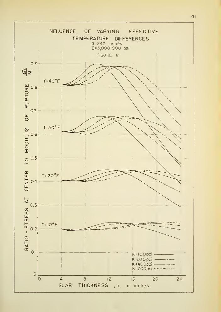
INFLUENCE OF VARYING EFFECTIVETEMPERATURE DIFFERENCES
a -240 inches
E = 3,000,000 psi
FIGURE 8
<
K = IOOP»Ci -K=20 0pci -
K=400pci -K =700pci-
8 12
SLAB THICKNESS ,h,
16 20
in inches
24

U2DISCUSSION OF RESULTS
Examination of Assumptions
In the derivation of the theory it was assumed that the 6 Lab had a
free edge boundary. This was believed to be Justifiable as the only
loads considered are those due to the weight of the slab; separate slabs
would be subjected to the 6ame effective gradient, thus resulting in
little shear or moment transfer. Actual field deflection measurements
reported by Hveem (l8) appear to substantiate this assumption.
Highway and airport pavement slabs are rectangular in shape rather
than circular. The circular shape was selected for study because
solutions could be obtained in closed form for finite slab sizes
.
Figure 9 represents a plot of the ratios of the normal stress at
the center of a circular slab to the normal stress at the center of an
infinitely long slab, as given by Westergaard, where the diameter of the
circular slab is equal to the width of the long slab. As noted earlier,
Westergaard' s solution was predicated on the assumption that the subgrade
provides full and continuous support to the pavement at all times; hence,
the stresses in the circular slabs were computed for full subgrade support,
Typical slab diameters corresponding to a W/J ratio of 8 are tabulated
below:*
K = 200 pci K - 700 pci
3 X 10g psi 0.15
3 x 10⁶ psi 0.153 x 10 psi 0.15
See page 59 for list of symbols
.
h W»2a T W=2a T
8"
10"12"
19.0'22. k'
25-7'
U.36°F4.87°F5.3^°F
13-9'16.U-18.3'
2.33°F2.6l°F2.85°F

43
I
2
3
4
5
6
7
8
9
10
11
1
213
14
15
16
17
18
19
RATIO
-SLAB
DIAMETER
(2a)
OR
WIDTH
OF
SLAB
TO
RADIUS
OF
RELATIVE
STIFFNESS
(J)
*
SLAB
5
STRIP
JPPORT
i
< z w1° -
a: y— V- »"~
1
£ »- ^° 2 Ou. o
cr 2uj
—I- u.2 U. OUJ o
* g^2^< z bUJ Q feiW O 2 §
to o oS8i = CO
a5 -
<o<TUJ —»-
COUJ5 -
o -K
» gCO u.
cr co Qi., 5
< k
fe ^ £o cr tO 2
ftTIO
N
IF
F1
cc h u
- -C5dc5b0d6c>0^oww»j3iS3« J* 0|±vy SS3dlSAH03H1 M3N J*

kk
Thus, for slab diameters larger than those corresponding to a
w/l ratio of 8, the shape of the slab does not appear to be of much
importance. The comparisons between computed and measured deflections
of warped slabs, to be reported below, lend further weight to the validity
of this observation.
Referring to the above tabulation, it is seen that the maximum
equivalent temperature difference for which the Westergaard theory is
applicable is very much lower than that commonly encountered in practice.
Comparisons with Available Measurements
Reference was made previously to measured slab deflections obtained
by Hatt (page 7). Curves 2 and k of Figure 1 are reproduced as solid
lines in Figure 10. Curve 2 represents the maximum position of the
slab during the drying cycle, whereas curve k depicts the maximum position
of the slab resulting from drying the slab completely and then introducing
water into the subbase and maintaining its level at the lower surface of
the slab. The deflection measurements were taken at times when the
temperatures were constant throughout the slab. No information was given
on the modulus of subgrade reaction of the foundation or on the modulus of
elasticity of the concrete. To compare the measured deflections with
those computed on the basis of the proposed theory, parameters thought to
be equivalent to those of Hatt were chosen.
As the modulus of elasticity of concrete is known to increase both
with the duration of wetting and age (^5), a modulus of elasticity of
3,500,000 psi was chosen for comparison with curve k, and 3,000,000 psi
for curve 2. The choice of appropriate moduli of subgrade reaction (K)
was made on the basis of the moisture condition of the base; thus, a K
of 50 pel was used for curve k and a K of 150 pci for curve 2.

45
COMPARSION BETWEEN OBSERVED AND
COMPUTED DEFLECTIONS— HATT
FIGURE 10
inIDIo
0.16-
0.12
0.08-
oo
Q
-0.04
0.04-
OBSERVEDAFTER HATT (14)
COMPUTEDE = 3,0O0,000f»*iK = 130 ?<<
a -. 185 IN.
h = 7 IN.
T =40 44°F
0.7 2.7 4.7 . 67 8.7 107 12.7
DISTANCE IN FEET ON CORNER DIAGONAL
OBSERVEDAFTER HATT (14)
COMPUTEDE»3,500,000piiK = 30 P"a = 185 IN.
h «7lN.T = 42 I3°F
0.7 2.7 4.7 67 87 107 12.7
DISTANCE IN FEET ON CORNER DIAGONAL

k6
The dotted curves in Figure 10 were obtained by substituting the
above parameters into the derived equations. Attention is directed to
computed effective temperature differences (T), shown in Figure 10, which
in this case reflect the effects of moisture gradients only.
No comparisons could be made with curve 3 of Figure 1, as the tempera-
ture and moisture gradients are zero. According to Hatt, the slight dis-
tortion is due to," the more pronounced contraction of the richer or
troweled surface than of the body of the slab."
The solid curve in Figure 11 represents the longitudinal deflection
curve of a rectangular (12 x 2k feet) slab, six inches thick, as
measured at the Portland Cement Association Laboratories, Skokie, Illinois.
This slab was subject to both temperature and moisture gradients.
Comparisons between theoretical and observed deflections for this slab
are of special interest, since both the modulus of subgrade reaction
(K = 80 pci) of the base and the dynamic modulus of elasticity (^,500,000
psi) of the concrete were determined. Reducing the dynamic modulus of
elasticity of concrete to an equivalent static modulus (^5), and using an
equivalent circular slab 2k feet in diameter, the dotted curve in
Figure 11 was obtained.
The correspondence between the computed and measured deflections,
as shown in Figures 10 and 11, offers substantial additional evidence
regarding the validity of the proposed theory and of the minor importance
of the shape of the slab on the critical stresses and deflections.

47
oa
< "•*•*.
Q O ****-^^^
LU z CL
t-3 g tr Q.
a. H- O2 < u. Ooo O
O<
ED
3,000,0
B0
pci
I44in.
6in.
30.5°
F
QCOCO
QUJz < > i~ n ii ii H ii
< orUJ ^ w *: o .c H
5QUJ>or
t- CO OzLU
( o1
1
UJ Ul _1
CO o 1
00
oUJor3
1 »
oz O
Z < u.
UJ _lUJ 1-
£ or
h- oUl a.
QQ1
COZ zo oCO \-or o<t UJ0. _i5 U_o Ulo Q
-8
§
8
oCM
to
oc
O-
OCM
O
s
s
oCM
o<H
Q
O
Oo
oo
o6
od
sd
00Od
o CMOd
od
S3M3UI in N0I1D3""133CI

U8Effective Gradients
The results of Figures 5A to 5L show that effective temperature
differences betveen slab surfaces of approximately ho degrees F. are
needed to produce tensile stresses which approach the modulus of
rupture of the slabs. It has been shown (5, ^1) that the temperature
gradient in highway pavement slabB is hardly likely to exceed 1-1/2
to 2 degrees F. per inch of slab thickness. Accordingly, critical warping
conditions can develop only if appreciable moisture gradients are also
present.
As demonstrated by Hatt (lb), moisture differences between the top
and bottom of slabs result in warping in much the same manner as tempera-
ture variations. However, very little is known of these moisture
gradients, due to the lack of suitable instrumentation capable of
measuring transient moisture gradients in concrete slabs.
Using fragments broken from specimen slabs and determining the
moisture content by drying in the laboratory, Teller and Sutherland C*l)
reported a seasonal variation of moisture content of 0.3 percent. However,
they state in their conclusions
:
There is a cyclic variation in slab length that is
entirely dissociated from temperature changes . The annualvariation in the length of the test sections from causesother than temperature changes is approximately equivalentto that caused by a temperature change of 30°F
., and the
maximum length occurs during the late winter when the ground
moisture content is greatest.
Hveem (l8) showed that changes in moisture content for 30 oven-dried
thin concrete discs (obtained from pavement cores), which were allowed
to soak for 7 days, evidenced a greater percent expansion for 2 3 of the
specimens than did a 90°F. increase in temperature. Hveem concluded that,
fc9
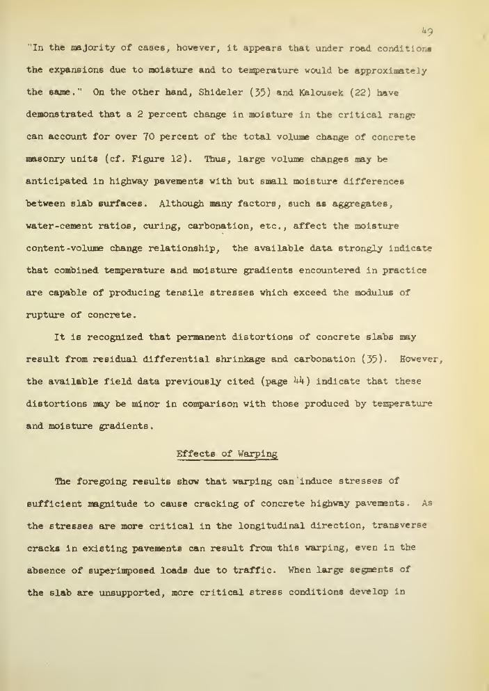
"In the majority of cases, however, It appears that under road conditlor.*
the expansions due to moisture and to temperature would be approximately
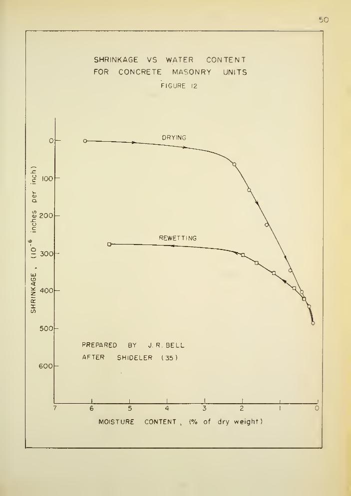
the same." On the other hand, Shideler (55) and Kalousek (22) have
demonstrated that a 2 percent change in moisture in the critical range
can account for over 70 percent of the total volume change of concrete
masonry units (cf. Figure 12). Hius, large volume changes may be
anticipated in highway pavements with but small moisture differences
between slab surfaces. Although many factors, such as aggregates,
water-cement ratios, curing, carbonation, etc., affect the moisture
content -volume change relationship, the available data strongly indicate
that combined temperature and moisture gradients encountered in practice
are capable of producing tensile stresses which exceed the modulus of
rupture of concrete.
It is recognized that permanent distortions of concrete slab6 may
result from residual differential shrinkage and carbonation (55)- However,
the available field data previously cited (page hk) indicate that these
distortions may be minor in comparison with those produced by temperature
and moisture gradients
.
Effects of Warping
Ihe foregoing results show that warping can induce stresses of
sufficient magnitude to cause cracking of concrete highway pavements. As
the stresses are more critical in the longitudinal direction, transverse
cracks in existing pavements can result from this warping, even in the
absence of superimposed loads due to traffic. When large segments of
the slab are unsupported, more critical stress conditions develop in
5C
SHRINKAGE VS WATER CONTENTFOR CONCRETE MASONRY UNITS
FIGURE 12
o _ DRYING
£ 100
Q.
CO _ _ _<u 200.c:oc
1
§ 300
REWETTING \n . , \
UJCD<* 400
5ito
500
PREPARED BY J. R. BELL
AFTER SHIDELER (35)600
1 ! !
7 6 5 4 3 2 1
MOISTURE CONTENT, (% of dry weight)
51
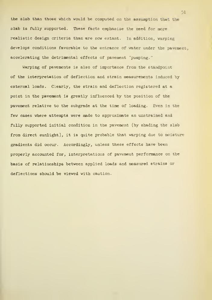
the slab than those which would be computed on the assumption that the
slab is fully supported. These facts emphasize the need for more
realistic design criteria than are now extant. In addition, warping
develops conditions favorable to the entrance of water under the pavement,
accelerating the detrimental effects of pavement pumping."
Warping of pavements is also of importance from the standpoint
of the interpretation of deflection and strain measurements induced by
external loads. Clearly, the strain and deflection registered at a
point in the pavement is greatly influenced by the position of the
pavement relative to the subgrade at the time of loading. Even in the
few cases where attempts were made to approximate an unstrained and
fully supported initial condition in the pavement (by shading the slab
from direct sunlight), it is quite probable that warping due to moisture
gradients did occur. Accordingly, unless these effects have been
properly accounted for, interpretations of pavement performance on the
basis of relationships between applied loads and measured strains or
deflections should be viewed with caution.
52
SUGGESTIONS FOR FURTHER RESEARCH
The results of this study indicate a vital need for a reliable and
accurate device to measure transient moisture gradients in hardened
concrete slabs.
An intensive search of the literature revealed the paucity of
reliable data on the warping of concrete slabs. Thus, conclusive evidence
regarding the reliability of vrarping theories is not available at this
time. The value of such a study, under field conditions, can hardly be
over-estimated. Advantage could be taken of recent knowledge and advances
in instrumentation to determine the absolute position of the pavement and
the pavement base at a sufficient number of locations to obtain at any
instant the contour of both the slab and its support. These data could
be correlated with the prevailing temperature and moisture gradients,
permitting valid comparisons between the theory and field performance.
The theory can readily be amplified to investigate the degree of
warping and pavement support induced by temperatures and/or moisture
contents which decrease with the depth of the slab. Extension of the
theory to account for effects of superimposed loads on the warped slab
would lead directly to improved design concepts for concrete highway
and airport pavements, and to design criteria for slab on ground
"
construction for homes
.
The development of mix designs that would materially reduce volume
changes in the hardened concrete due to moisture and temperature varia-
tions, and due to carbonation, would be a major contribution to improved
performance of concrete highway and airport pavements.

53
CONCLUSIONS
1. On the basis of the assumptions stated herein, a theory has been
developed whereby the stresses, deflections, and degree of support
of slabs, subject to warping caused by ambient temperature and/or
moisture gradients, can be computed for finite slab sizes.
2. Comparisons with available field data strongly indicate that the
theory is applicable to concrete pavements not subjected to super-
imposed loads. Under these circumstances, the following conclusions
are Justified:
a. Combined temperature and moisture gradients encountered
in practice are capable of producing tensile stresses
which exceed the modulus of rupture of concrete highway
slabs
.
b. Equivalent temperature gradients at which warped slab6
would maintain full contact with their support are very
much lower than those normally encountered in practice.
c. Warping due to temperature and/or moisture gradients
develops conditions favorable to the entrance of water
under the slab, accelerating the detrimental effects
of pavement "pumping." Warping is also a contributing
factor to the development of pavanent blowups.
d. Consideration of the effects of warping is a necessary
prerequisite to the interpretation of pavement perform-
ance on the basis of measured strains and, or deflections
of the slab.
e. In the critical shrinkage range, a moisture
gradient of one percent can cause warping
equivalent to a 20 degree F. temperature
gradient. Accordingly, cracking may occur
at small temperature gradients if moisture
differences between slab surfaces are only
a few percent.
f. A comprehensive investigation of warping in
highway pavement slabs, carried out under
field conditions with due consideration to
defining the initial position and the degree
of support , would contribute significantly
to the improvement of design concepts.
5» The concepts developed in this study can provide the basis for the
solution of a number of problems involving warping of slabs; for
example, "slab on ground" construction for homes, icing of lakes,
and the like.

BIBLIOGRAPHY

55
BIBLIOGRAPHY
1. Allen, C. W. and Barbee, J. F., "Pavement Performance Surveys,
"
Highway Research Board Proceedings , Vol. 26 (1946).
2. Anderson, F. P., "Investigational Concrete Pavement in Kentucky,Highway Research Board Proceedings , Vol. 20 (I9U0).
5. Bauschinger, J., "Tests of Different Portland Cements, Mi ttel lunge
n
Mechaniach-Technisches Laboratorium , Technischen Hochschule, Munich,1579, (In German).
k. Bone, A. J., Crump, L. W., and Roggeveen, V. J., "Control ofReflection Cracking in Bituminous Resurfacing Over Old CementConcrete Pavements," Highway Research Board Proceedings, Vol. 33(195M.
5. Bradbury, R. D., "Reinforced Concrete Pavements," Wire ReinforcementInstitute , Washington, D. C, (1938).
6. Breeman, W., "Current Design of Concrete Pavement in New Jersey,Highway Research Board Proceedings , Vol. 28 (1948).
7. Buchanan, S. J., and Khuri, F. I., "Elastic and Plastic Propertiesof Soils and Their Influence on the Continuous Support of RigidPavements, " U. S. Army Corps of Engineers , June, 1954.
8. Cashell, H. B. , and Teske, W. E., "Continuous Reinforcement inConcrete Pavements," Highway Research Board Proceedings , Vol. 34 (1955)
9. Farrel, F. B., and Patrick, H. R., "The Capital Investment inHighways, " Highway Research Board Proceedings , Vol. 32 (1953)
•
10. Friberg, B. F., "Frictional Resistance Under Concrete Pavements andRestraint Stresses in Long Reinforced Slabs," Highway Research BoardProceedings , Vol. 33 (195^)-
11. Friberg, B. F., "Pavement Research, Design, and Prestressed Concrete,
Highway Research Board Proceedings , Vol . 34 ( 1955 )
•
12. Geldmacher, R. C, Anderson, R. L. , Dunkin, J. W., Partridge, G. R.,
Harr, M. E., and Wood, L. E., "Subgrade Support Characteristics,
Experimental, Theoretical," Highway Research Board Proceedings ,
Vol. 36 (1957).
13. Goldbeck, A. T., and Jackson, F. H. , The Expansion and Contraction
of Concrete and Concrete Roads," Bulletin No. 532, U. S. Department
of Agriculture , (1917).
Ik. Hatt, W. K., 'The Effect of Moisture on Concrete," Transactions of
the American Society of Civil Engineers, Vol. 89 ( 1926 )
.

5615* Hetenyi, M. , "Beams on Elastic Foundation, " The University of
Michigan Press, Ann Arbor, Michigan, (1946).
16. Highway Research Board Research Reports , No. 3B, InvestigationalConcrete Pavements, Progress Reports of Cooperative ResearchProjects on Joint Spacing," (1945).
17- Highway Research Board Special Report 4 , "Road Test One-MD,' (1952).
18. Hveem, F. N., "Slab Warping Affects Pavement Joint Performance,Journal of the American Concrete Institute , Vol. 47 , pp. 797-808
(1951).
19- Hveem, F. N. , "Types and Causes of Failure in Highway Pavements,'Preprint of Paper Presented at 37th Annual Meeting of the HighwayResearch Board, Washington, D. C, January, 1958.
20. Jackson, F. H., and Allen, H., "Concrete Pavements on the GermanAutobahnen," Journal of the American Concrete Institute , Vol. 44,
pp. 933-976 (19W:
21. Joint Committee on Standard Specifications for Concrete andReinforced Concrete, "Recommended Practice and Standard Specificationsfor Concrete and Reinforced Concrete," American Concrete Institute,1947.
22. Kalousek, G. L., O'Heir, R. J., Ziems, K. L., and Saxer, E. L.,
"Relation of Shrinkage to Moisture Content in Concrete Block,
"
Proceedings of American Concrete Institute , Vol. 50, (1954).
23. Kelly, E. F., "Applications of the Results of Research to the
Structural Design of Concrete Pavements," Public Roads , Vol. 20
(1939).
24. Lang, F. C, 'Temperature and Moisture Variations in ConcretePavements," Highway Research Board Proceedings , Vol. 21, ( 1941 ).
25. Lang, F. C, "Investigational Concrete Pavement in Minnesota,"
Highway Research Board Proceedings , Vol. 20, (1940).
26. Lewis, D. W., "The Performance of Concrete Resurfacing in Indiana,'
Highway Research Board Proceedings , Vol. 30, (1950).
27. Marin, J., "Engineering Materials, " Prentice -Hall, Inc., N. Y.,
(1952).
28. Melan, E., and Parkus, H., "Warmespannungen," Springer -Verlag, Vienna,
(1953).
29. Older, C, "Highway Research in Illinois," Proceedings of American
Society of Civil Engineers, Vol. 50, pp. 175-217, (1924).

57
30. Paxeon, G. S., "Investigational Concrete Pavement In Oregon,Highway Research Board Proceedings , Vol. 21, (19^1).
30a. Phillippe, R. R., and Mellinger, F. M. , Structural Behavior ofHeavy-Duty-Concrete Airfield Pavements," Highway Research BoardProceedings , Vol. 31 (1952).
30b. Pickett, G. , and Janes, W. C, "Bending Under Lateral Load of aCircular Slab on an Elastic Solid Foundation, ' Proceedings of theFirst Midwestern Conference on Solid Mechanics , Urbana, Illinois (1953),
31. Portland Cement Association , "Concrete Pavement Design, Chicago, (1951)
,
32. Reagel, F. V., 'Investigational Concrete Pavement in Missouri,"Highway Research Board Proceedings , Vol. 21, (19AI).
33. Roberts, S. E., "Cracks in Asphalt Resurfacing Affected By Cracksin Rigid Base," Highway Research Board Proceedings , Vol. 33, (195M-
3^. Schleicher, F., "Kreisplatten auf elastischer Unterlage, " JuliusSpringer, Berlin, (1926).
35. Shideler, J. J., "Investigation of the Moisture -Volume Stabilityof Concrete Masonry Units," Bulletin D3 , Portland Cement Association
,
Chicago, (1955).
35a. Siess, C. P., and Newmark, N. M. , "Rational Analysis and Design ofTwo-Way Concrete Slabs," Proceedings of the American Concrete
Institute , Vol. 1*5 (19^9) •
36. Spangler, M. G., "Stresses in the Corner Region of Concrete Pavements,
Iowa Engineering Experiment Station , Bulletin 157 (19^2).
37. Sparkes, F. N., "Stresses in Concrete Road Slabs," Structural Engineer ,
Vol. 17, Part 2, pp. 98-II6, (1939).
38. Sparkes, F. N., and Smith, A. F., "Concrete Roads," Edward Arnold
and Company, London, (1952).
39. Stanton, T. E., "Investigational Concrete Pavement in California,"
Highway Research Report No. 3B , (19^5)-
ho. Sutherland, E. C, discussion to, "Thickness of Concrete Pavements
for Highways," by J. H. Moore, Transactions of American Society of
Civil Engineers , Vol. 121, ( 19567"!"
1*1. Teller, L. W., and Sutherland, E. C, "The Structural Design of
Concrete Pavements," Public Roads , October, 1935; November, 1935;
December, 1935; September, 193b; October, 1936; April-May-June, 19^3-
k2. Terzaghi, K. , "Evaluation of Coefficients of Subgrade Reaction,'
Geotechnique, Vol. V, December, 1955-

58
43. Thomlinson, J., "Temperature Variations and Consequent StressesProduced by Daily and Seasonal T mperature Cycles in Concrete Slabs,Concrete and Constructional Engineering ,
(19U0).
44. Timoshenko, S., "Theory of Plates and Shells," McGraw-Hill,New York, (19^0).
45. Troxell, G. E., and Davis, H. E., "Composition and Properties ofConcrete," McGraw-Hill, New York, (1956).
46. U. S. Department of Commerce, Bureau of Public Roads, HighwayStatistics - 1953," U. S. Government Printing Office, Washington,D. C, (195*0.
47. Westergaard, H. M. , "Stresses in Concrete Pavements Computed byTheoretical Analysis," Public Roads , April, 1926.
48. Westergaard, H. M., "Analysis of Stresses in Concrete Roads Causedby Variations of Temperature," Public Roads , May 1927.
49. Westergaard, H. M. , "What is Known of Stresses," Engineering News -
Record, January 7, 1937-
49a. Westergaard, H. M. , 'New Formulas for Stresses in Concrete Pavementsof Airfields , " Transactions of American Society of Civil Engineers
,
Vol. 113 (19^8).
50. White, L. V., and Peyton, R. L., "Condition of Concrete Pavementin Kansas as Affected by Coarse Aggregate," Highway Research BoardProceedings , Vol. 25 (1945).
51. Woods, K. B., and Shelburn, T. E., "Pumping of Rigid Pavements in
Indiana, " Highway Research Board Proceedings , Vol. 23 (19^3).
52. Woods, K. B., and Gregg, L. E., "Pavement Performance Related to
Soil Texture and Compaction, " Highway Research Board Proceedings ,
Vol. 24, (1944).
53- Woods, K. B., "Influence of Subgrades and Bases on Design of Rigid
Pavements, Reprint No. 59, Engineering Experiment Station, Purdue
University, July, 1950.
53a. Woods, K. B., Sweet, H. S., and Shelburne, T. E., Pavement Blowups
Correlated with Source of Coarse Aggregate," Highway Research Board
Proceedings , Vol. 25 (1945).
54. Yoder, E. J., "Pumping of Highway and Airfield Pavements," Highway
Research Board Proceedings, Vol. 36 (1957).

APPENDIX I
59
Nomenclature
Symbols In parentheses represent the dimensions of:
F forceL * lengtht temperature
v = deflection, positive in the downward direction, (L)
q = distributed load due to weight of slab (F/L2
)
K = modulus of subgrade reaction (F/L )
op = reaction of subgrade, p = Kw, (F/L )
h = slab thickness (L)
M = Poisson's ratio
E = Young's modulus
D = —^—=- = the flexural rigidity of the slab (FL)
12(l-H )
Wic = radius of relative stiffness (L)
a «B linear coefficient of thermal expansion (t )
T = temperature difference between upper and lower slab surfaces (t)
r = radial distance (L)
a = slab radius (L)
b = radial distance to point of zero deflection (L)
rp =
r
w'(r) = slope at point r
V(r) = shear at point r (F/L)
M(r) radial bending moment at point r (FL/L)
_2o(r) = radial normal stress at point r (FL )
_2c^j =» normal stress at center of slab (FL )

C. = coefficients
Z.(p) Bessel functions
Z '(p) = first derivative of Z (p)i
2l
V2 - (d
+X d
)
dr
In = natural logarithm

APPENDIX II

61
General Solution
The general differential equation for the deflection of a thin
circular plate resting on an elastic foundation is given (}4) as:
V'w = SgE. (1)
The solution of equation (l) was obtained by Schleicher (}4) in the
following form:
v -J (1 + C
1Z1(p) + C
2Z2(p) + C
5Z5(p) + C
uZu (p)J. (2)
where
zx ( P ) = \ [j
o(p^ ) + j
o(pV^ )]
z2 ( P ) --§ [j
o(pVTT ) - j
o ( p sTI )]
z3
( P ) = z1 ( P ) + | [y
o(p >£i ) - y
o(p VT )]
Z^(p) = z2 ( P ) + | [Y
Q (p</+T ) + y
o(p vTT )).
J (p) and Y (p) are Bessel functions of the first and second kind,
respectively, both of zero order. The Z functions, Z,(p) and Z~(p),
which are of particular interest in the present problem are the more
common Ber (p) and -Bei (p). Z,(p) and Z. (p) are related to the
Kei(p) and Ker(p) functions, respectively.
For the region where the plate is unsupported (Figure 2),
equation (l) reduces to
V*w =j.
[k
)
The solution of equation (4), as given by Timoshenko (44), is:
w = C.- + C,-ln r + C_r + Cgr In r + g«j . (5)
(3)

62
To obtain the particular solution of interest, the following
conditions must be satisfied:
aV [0) =
b1 v
l:o) =
c wl
'b) =
d V2 '
a) =
e ,M2
'a) =
f W2
'b) =
g V» = w2
(b)
h"l '» = M
2(b)
i IY1
1» = V2
(b).
(6)
The subscripts 1 and 2 refer to the supported and unsupported regions
of the plate, respectively (see Figure 2).
a) W;L '(0) = 0.
dwV =dF
=i<7
t cizi'
(p) + C2Z2,(p) + c
3Z3'<p) + <W (p)) •
As p approaches 0, Z '(p), Z '(p), and Z,'(p) approach and Z^'(p)
approaches infinity; therefore, C^ must equal 0.
b) v1(o) = 0.
The shear in a thin plate subject to a gradient T/h (28) is
V = D (*L [A + a(l + n) I ]} (7)
As the gradient is assumed to be independent of the radius, equation (7)
reduces to
V - D (^ ^w} (8)
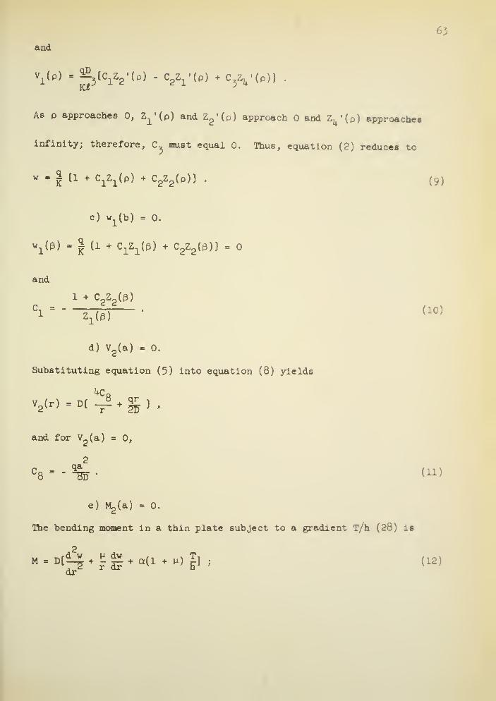
63
and
v1(p) - ^{C^'Cp) - (^(p) + C Z
4'(p)} .
As p approaches 0, Z^p) and Z2'(p) approach and Z
4'(p) approaches
infinity; therefore, C must equal 0. Thus, equation (2) reduce* to
w • i {1 + CjZ^p) + C2Z2 (p)}
.
( 9 )
c) w1(b) = 0.
wx(3) - | (i + c^e) + c
2z2 (^)}
= o
and
1 + C Z (p)ci " " z
l(p)•
< 10 »
d) V2(a) - 0.
Substituting equation (5) into equation (8) yields
and for V~(a) = 0,2 ,
2
^8dCa - - %T . (11)
e) M^a) = 0.
The bending moment in a thin plate subject to a gradient T/h (28) is
M-DCJj^g+oU + lOgli (12)
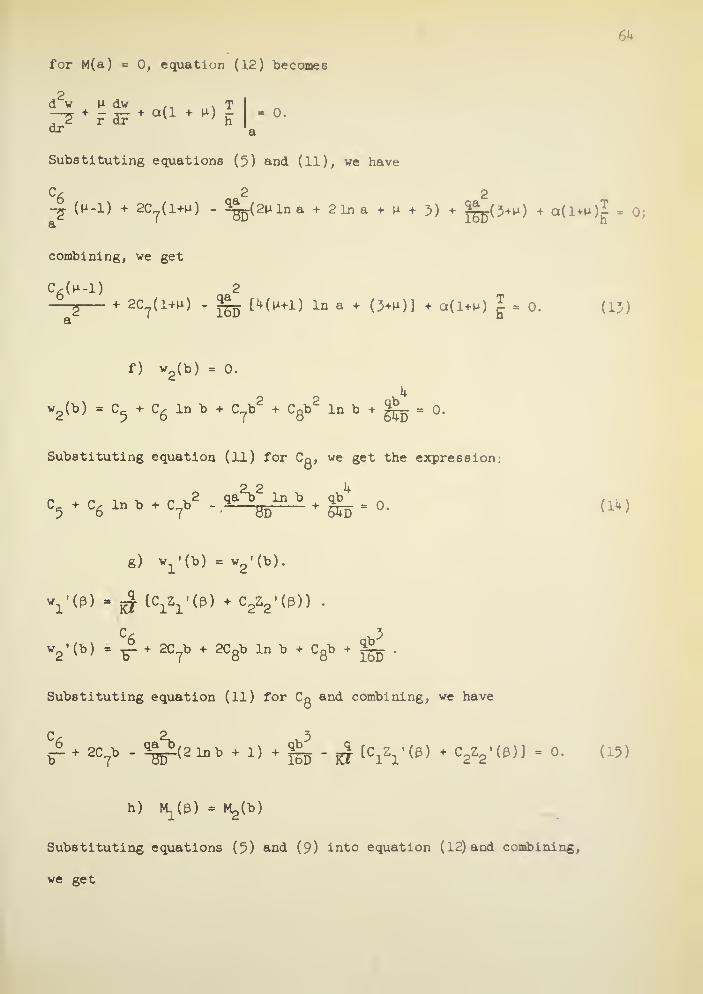
6k
for M(a) = 0, equation (12) becomes
2
7T +r dF
+ a(1 + •*>h " °-
dr '
a
Substituting equations (5) and (11), we have
C6
2 2-g. (n-1) + 2C
T(1+M) - 5a^(2nlna + 21na + n + 3) + ^pO^) a(l-Hi)I = 0;
combining, we get
C6(H-1) 2
2+ 2C
7(1+H) - g_ [4(u+l) In a + (3+u)] + a(l+n) | - 0. (15)
f) w2(b) = 0.
It
w2(b) = C
5+ C
6In b + C b
2+ C
Qb2
In b + 3JL. = 0.
Substituting equation (ll) for Cg, we get the expression:
g) w1'(b) = w
2'(b).
w1
,
(p) - £ (c^'O) + c2z2-(p)) .
w2'(b) = ^ + 2C
?b + 2Cgb In b + Cgb + g_ .
Substituting equation (11 ) for Cg and combining, we have
C 2. 3
tr+ac
7b -^2lBb + 1) + raj-CT Ic
izi,(p) + C
2V< P)] =0 - (i5)
h) ^((3) = M^b)
Substituting equations (5) and (9) into equation (12) and combining,
we get

65
C 2 2
-|(n-i) + 2c?(i+n) - 5^_ [2(i+n)inb+ (3+»i)] 3g_(3*0
-^ (c^O) - U-^i'l-), . c , z (t3) +
d-M)z2 '( P ) n . 0> (16)
i) v1(b) - v
2(b).
Substituting equations (5), (9), and (10) into equation (8) and combining,
we get
z2-(p) - z^eHa2^2
]^°2 = - {
z2 (e)
z2 '(a) +z
1 -(e) z^e)3
• (17)
Calculation of the Stress Equations
As previously noted, equation (12) expressed the radial bending
moment as
M(r). D [*-£+ ££«<!*) £] '
dr
TSolving for a(l+u) r- in equation (13) and substituting into equation (12)
we obtain
«£> . C6(,-l)(4 - 4) 4 (1+U ,ln t - , i*& (a* - r
2) .
r a
The radial stress in a thin plate (28) is
._Eh
, Hlri,
.
r2(1-P ) D

66
thus,
', " ,"774,lC6<-1 ><4 - 4> * ^-> * F -^ <—» • (18)
d\i-v ; r a
Equation (l8) is valid for the tensile stress at the upper surface of the
slab for b < r < a.
In a similar manner the stress at0<r<bor0<p<3 is found
to be
Fh n(l-H)Z '(p) (l-M)Z '(d)
°p - ^W [5> (ci[z2^) r— J - c
2 i zi(p>
+—r— ])
2(1-M ) Kl
+ a(i + u)I ) . (19)
At p = 0, equation (19) reduces to
C2q
° 2(1-^) 2KT[- — (1 + H) + a(l + H) ? ] . (20)

APPENDIX III
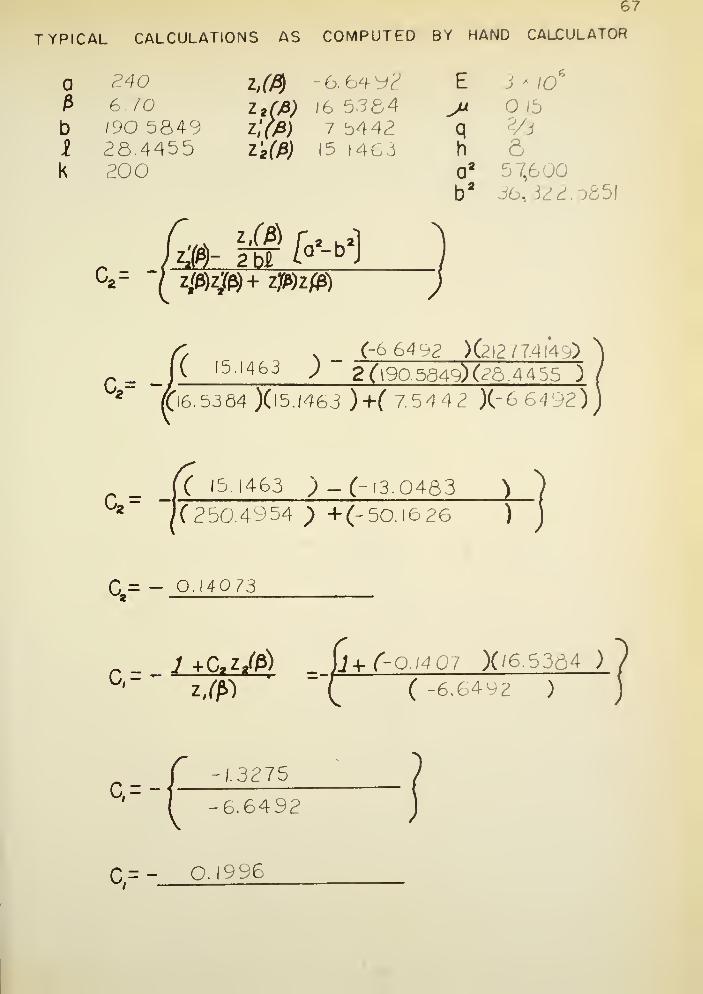
67
TYPICAL CALCULATIONS AS COMPUTED BY HAND CALCULATOR
240 z,(fy -6.6492 E i * io6
6.70 z 2 (jB) (6 5384 jx 6b i
rJO. 5849 Z,Y>9) 7 b442 q 2/3
i 28.4455 z'g (fi) 15 1463 h 6k 200 0* 57,6 ;
b* 351
v _ (-6 64 92 ) (212 77.414,015.1463 ^ 2 (l90. 5849) (28. 4 4 55 )
t'6.5364 )(l5./46J ) +( 7.5442 )(- 6 J492)
( '3.1463 ) -(-13.0483 )
'(250.4954 ) +(-50.1626 )
q = _ Q.I4Q 73
r _ 7 +CZ^) (j+f-Q/407 X/6.5364 )
°J ~ Z.0) T C -6.6492 )
Q=--1.3275
6.6492
C=- O.I996
68
q 'F*q
[C
.
r -C2 &]+^DK?2 C, r- Cj, S (3+//)+ 2(ln b)(H/)
;(3-/fl
r-z(A)-i^2zUft-(i633M- (JS^B^2r
/9v
' (6.70)
= (16.5384) -( 0. 95 71 ) - 15. 5813
g*Z,(g) + <'-^ZJ(P) = (- 66^) + (Q&5)(l5./46J)1
/3 ( 6. 70 )
= (-6.649?) + (/. 92/5 ) -47^77
C,y-(-Q/995)(/5.58/3)" -3.1054
C2S = (-O.I407)(-4/^77)= Q6652
C,iT-C 2 8 = 3.7 736
kF* 6.17S>4M06
» (Qgx-CtS)(--U-)= -2.33/8 ^/Q
5
a
G = ^- [(3^)4 2(1 +P )lneb] -
,|o ( 3+//
)
lnb= 5.2 5
b'= 36322.3659
G= ( 5.498+f3.I5M2.3)(5^]-j^^P15)' 21% Id22 «
Fj. I [(C,eT -C2 6) ^r] -
GJ= -<?.3318^0"
5+ 76.2522 »t0"
s
F= 75. 92Q4
69
C'= c =KT rQZ;((3)+cX(/3)]+J
2 f )
J-ft-te"*l)-ijy
C'= ^7578«W-a/996 X7-^442 )+(-OJ407 JI5.I46 3 )( + J
•fQ= |(/.7b7fl x/o
7
)j- 3.6 3
[
;69 Mazb _= 1047.9/77 MO
(2lnb I) = H.5
-§jy-(2 lnb + l) « 12051.0535 x \0
V--b
I6D3 30.4O75 * 10
J= 117Z.Q645»IQ"
C'= [(-6.39^9MO)+0l7^.O643'IO4
)J
C= 1/65.6717 MO-1

'0
ji-, 5b+0-^)C,,W„ )C
,-*
•£*- = |-[c'('^/, )-F:b?° -IO'3&9.2609H05
^^^^^6feS^3l - Br
H= 7 79 703- /
Q"4
_ MJ_ = f/.4962*/0J+ |"73.547N0^-f77.9703«/CF]
j^- = -2.9Z70 MQ"5
Dq
1 iDqi (IV) *

APPENDIX IV

oroo<ra.
z<5
1ri to
oujor
or
O
5 |in 2
2 zuj 50.
in
<n- OJ
Ma
Ol
M
a»
(VJ
Ml N1-< 01-1
^ N> •UJ ««.
t- O
«ii
>O CC2 O< z<T 2a- z
<2
_l —_l4
UJ
SB_l
§ °uj 9
g.°°.
1- ow
IIw £
, i
5 t-
at zz <J
DCa. jo
i
UJk-<3 H<>UJ
•te
"J Jfi- ™S sZJ OD
§ «UJ CD
E
jDO
UJ CO
w 6
11*uj a.
!§'
CM
UJ ISj
>- '
5 S_i -
UJ ^
?5.5°
Q ©
UI t- uo zz S o£ § «UJ UJ J$ 2.
a~ ° 2(/>(/>:2 2a. aUJ UJ
,
«J CD !
1CD >-
j-i
SfcB
teg
> ucuj a.
«v
MKl
UJ
fe< ^_l
rs|
>UJ "V.
B-
er\
2
<a.
©

APPENDIX V

72
<
< 3q: o
<Q
o
ei
c
t*^
1^
i
of
t~
~
1
Ul1- *~3 X£ <f>s ~o *
o1
UIT<0. t-LU —<r
x.
CL w—
GM
© o <i
- o /x tr /lu q. y
II
i
_ca.
fo \
a.c
—- \h-i
a-c
/IUJ /
1 /UJ ~Tf /»—3 _
lAj /a.
2 acoo
i
UJ
f
(^\
t
C
I
(W)
a.c
oFUl UJ c
i o«
«j
uj r^^1
»-i
=> c
2 5=O cO Cvj
1

73
0—
00
cc cc
2 O

74
O
<CD<
O
UJct=> oF
t*>^^X
C\J
If)
**t"
1 k
W -H •°~.
0.x
2 in CVJ
o wU |1
CVJ
v- <t- oX O
w %1
w \ ' /
1 \ ac /1
w\ W /
Aj
\
no ~o
o5Wt
c
J I
=w
•*
cUJ
t CM ©-o
J I
UJ
= ccl
SOo
CVJ

75
1
Q.C
UJ
0- f
1
cL«=
c

VITA

76
VITA
Milton Edward Harr was born Oct ,ber 19, 1925, at Chelsea,
Massachusetts, and received his early educati ^n in the Chelsea Scho 1
System.
In June, 19^3, after graduation fr .m Chelsea High School, he
enlisted in the United States Navy. After participating in the
Normandy Invasion, Mr. Harr was transferred to the United States
Marine Corps. He served with the Third Marine Division on Guam and
Iwo Jima. Mr. Harr has received the Order of the Purple Heart, the
Presidential Unit Citation, and the Navy Unit Commendation.
Upon separation from the service in August A 19^5, he entered
Northeastern University, receiving his B.S. in Civil Engineering in
June, 19^9 • During the summer of 19^+8^ he was employed as an Assistant
Resident Engineer by the Massachusetts Department of Public Works,
Highway Division. Upon graduation, he went to work for the Bureau of
Reclamation in Provo, Utah. In September, 19^9, he returned to the
Massachusetts Department of Public Works, where he participated in the
design and construction of several major highways
.
In 1953, he resigned his position and jjined the staff of Rutgers
University, receiving his M.S.C.E. in June, 1955. Upon graduation, he
went to work for Howard, Needles, Tammen, and Bergendoff as Area Engineer
on the widening of the New Jersey Turnpike. He resigned his position in
September, 1955, to join the staff of Purdue University as an Instructor
in Civil Engineering.
Mr. Harr is a member of Sigma Xi and Chi Epsilon. He is married
and has three children.