03 Options and Alternatives - TfL
37
[Type text] 03 Options and Alternatives Environmental Statement Volume I
-
Upload
khangminh22 -
Category
Documents
-
view
2 -
download
0
Transcript of 03 Options and Alternatives - TfL
[Type text]
03 Options and Alternatives
Environmental Statement
Volume I

03 Options and Alternatives
3-1
Introduction
3.1 This chapter of the Environmental Statement (ES) sets out the main alternatives to the Northern Line Extension (NLE) which have been considered by Transport for London (TfL) and the main reasons for the choices made, taking into account the environmental effects of those choices. This is in accordance with the requirements of Rule 11(2) of the Transport and Works (Applications and Objections Procedure) (England and Wales) Rules (Ref. 3-1) and the EIA Regulations (Ref. 3-2).
3.2 Applicants are advised under guidance issued by the Department for Transport (DfT) to interpret this requirement as applying to not just alternatives to the entire project that may have been considered, but also to any alternative site locations or route alignments that have been studied. In the light of this, a hierarchical approach has been adopted in order to document the options and alternatives considered during development of the NLE by TfL (and by the previous Promoter, Treasury Holdings UK Ltd (THUK)).
Structure of this Chapter
3.3 This chapter begins with a short historical overview of the NLE, noting the change of Promoter from a private developer to TfL. This is followed by the aims and objectives of the NLE, which have been used to inform the assessment of options and alternatives. It then describes how the NLE developed from initial concept to final design, identifying three ‘tiers’ of development, as follows:
• Tier 1 – Identifying the need for public transport intervention to enable the Vauxhall Nine Elms and Battersea (VNEB) Opportunity Area (OA) to be developed to an appropriate density, and identifying an extension of the Northern line as the preferred strategic option;
• Tier 2 – Considering a number of broad route and station options from Kennington to the Battersea Power Station (BPS) site, and selecting the proposed option; and
• Tier 3 – Investigating various project and site specific options and alternatives around construction methodologies (including worksites), locations and layouts of stations and shafts.
3.4 This chapter provides a summary of options and alternatives considered as part of the project development, including TfL’s scheme review which began in early 2012. Each tier includes information summarising how consultation was used to inform design development; additionally, an overall summary of the consultation activity is provided towards the end of the chapter.
3.5 Details of the policy context for the NLE are set out in Chapter 5: Planning Policy Context. A description of the works required for the proposed option is given in Chapter 4: Description of the NLE. The Design and Access Statement (DAS) (see ES Volume II: Appendix M) explains the rationale for the elements of the proposal from a design perspective.
Historical Overview
3.6 Until December 2011, THUK was the promoter of the NLE and the developer of the BPS site, acting as an agent for the site’s owner, Real Estate Opportunities (REO).
THUK’s role as promoter of the NLE arose as part of their work to unlock development capacity at the BPS site. Work undertaken by Steer Davies Gleave (SDG) identified the NLE as the preferred option and in developing the scheme detail, THUK worked closely with TfL in order to ensure both its strategic fit and that the design satisfied TfL’s requirements. The BPS Planning Permission then places a series of commitments on the developer to help bring forward the NLE project.
3.7 TfL took responsibility for the development and promotion of the NLE when REO went into administration in December 2011. On assuming this responsibility in January 2012, TfL reviewed the proposal and a number of changes – for example the deletion of the Claylands Road shaft – were made. The Battersea Power Station Development Company (BPSDC) is now the developer of the BPS site, and planning permission to develop the site (with the NLE) remains in place.
Statement of Aims
3.8 The primary aim of the NLE is to encourage economic growth in London and the wider UK economy by facilitating the sustainable regeneration and development of the VNEB OA. This includes the creation of a major new sustainable residential, business and leisure district in London’s Central Activities Zone (CAZ).
3.9 The London Plan (2011) designates VNEB as an OA with the potential for 16,000 new homes and 20,000-25,000 new jobs. This level of development cannot happen sustainably without the appropriate transport infrastructure to catalyse and support economic growth of this scale.
3.10 The NLE will achieve its primary aim by providing two new stations to improve access to the London Underground network in an area which is in part characterised by poor access to public transport, thereby benefiting both new and existing residential and business communities. In comparison with other parts of central London, the VNEB OA is currently poorly served in terms of public transport accessibility and also in absolute terms, as evidenced by its Public Transport Accessibility Levels (PTALs) which indicate the relative density of the public transport network at a given location. While most of central London achieves a PTAL of 6 (on a six-point scale), the central and western sections of VNEB have PTALs of 1 and 2, with Level 6 only at the eastern end around Vauxhall.
3.11 The primary aim of the NLE is consistent with a number of objectives set out in the National Planning Policy Framework (NPPF) (2012), the London Plan, the VNEB Opportunity Area Planning Framework (OAPF) (2012) and Borough planning policies.
Tier 1 - Modal Options and Alternatives
3.12 In February 2008, initial work was undertaken by SDG on behalf of THUK(Ref 3-3) into the feasibility of developing one of the key OA sites at BPS and it concluded that development here would require a step change in public transport accessibility only achievable by tram or tube schemes.
3.13 In parallel, the Greater London Authority (GLA) was preparing a draft OAPF for VNEB, setting out the potential scenarios for the scale and mix of development which could happen within the OA (see Table 3-1). Consultation on the draft OAPF was conducted from November 2009 and the final OAPF was formally adopted by the Mayor in March 2012.
03 Options and Alternatives
3-2
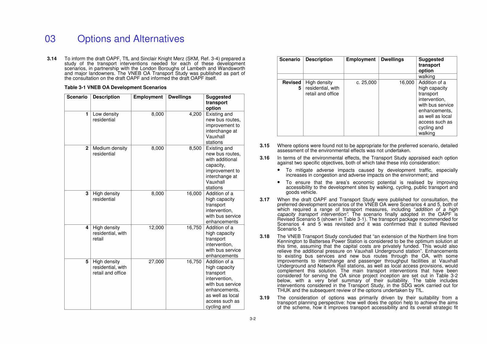
3.14 To inform the draft OAPF, TfL and Sinclair Knight Merz (SKM, Ref. 3-4) prepared a study of the transport interventions needed for each of these development scenarios, in partnership with the London Boroughs of Lambeth and Wandsworth and major landowners. The VNEB OA Transport Study was published as part of the consultation on the draft OAPF and informed the draft OAPF itself.
Table 3-1 VNEB OA Development Scenarios
Scenario Description Employment Dwellings Suggested transport option
1 Low density residential
8,000 4,200 Existing and new bus routes, improvement to interchange at Vauxhall stations
2 Medium density residential
8,000 8,500 Existing and new bus routes, with additional capacity, improvement to interchange at Vauxhall stations
3 High density residential
8,000 16,000 Addition of a high capacity transport intervention, with bus service enhancements
4 High density residential, with retail
12,000 16,750 Addition of a high capacity transport intervention, with bus service enhancements
5 High density residential, with retail and office
27,000 16,750 Addition of a high capacity transport intervention, with bus service enhancements, as well as local access such as cycling and
Scenario Description Employment Dwellings Suggested transport option walking
Revised 5
High density residential, with retail and office
c. 25,000 16,000 Addition of a high capacity transport intervention, with bus service enhancements, as well as local access such as cycling and walking
3.15 Where options were found not to be appropriate for the preferred scenario, detailed assessment of the environmental effects was not undertaken.
3.16 In terms of the environmental effects, the Transport Study appraised each option against two specific objectives, both of which take these into consideration:
• To mitigate adverse impacts caused by development traffic, especially increases in congestion and adverse impacts on the environment; and
• To ensure that the area’s economic potential is realised by improving accessibility to the development sites by walking, cycling, public transport and goods vehicle.
3.17 When the draft OAPF and Transport Study were published for consultation, the preferred development scenarios of the VNEB OA were Scenarios 4 and 5, both of which required a range of transport measures, including “addition of a high capacity transport intervention”. The scenario finally adopted in the OAPF is Revised Scenario 5 (shown in Table 3-1). The transport package recommended for Scenarios 4 and 5 was revisited and it was confirmed that it suited Revised Scenario 5.
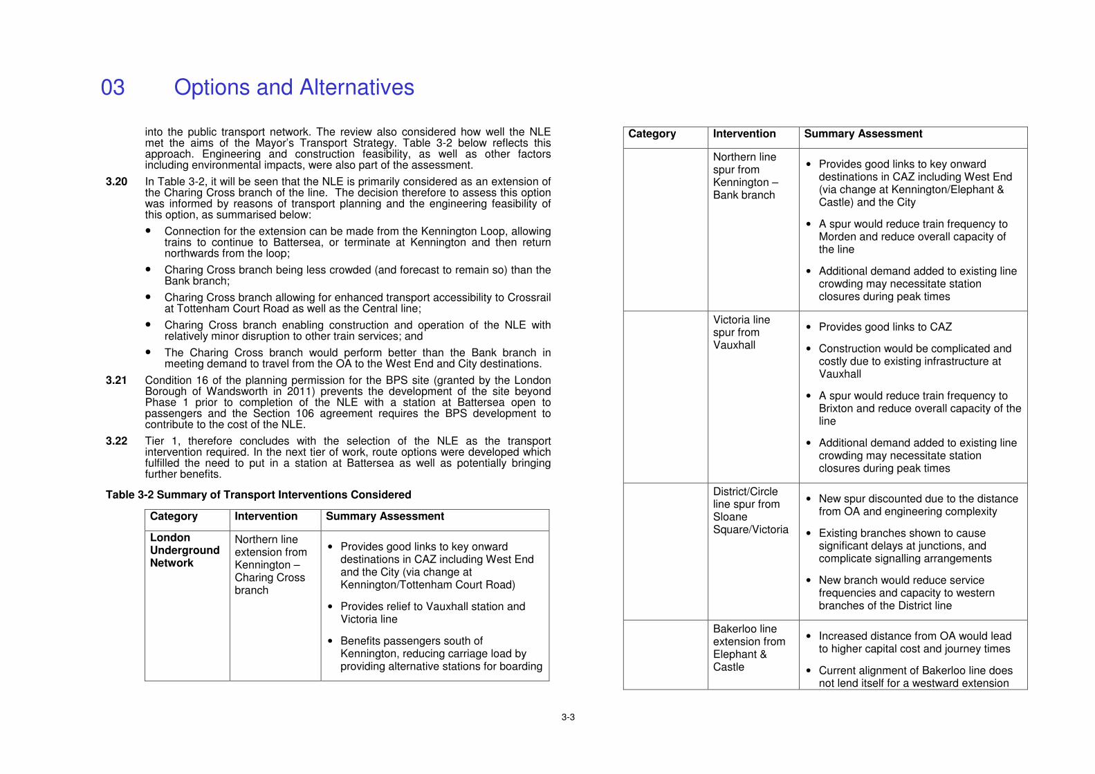
3.18 The VNEB Transport Study concluded that “an extension of the Northern line from Kennington to Battersea Power Station is considered to be the optimum solution at this time, assuming that the capital costs are privately funded. This would also relieve the additional pressure on Vauxhall Underground station”. Enhancements to existing bus services and new bus routes through the OA, with some improvements to interchange and passenger throughput facilities at Vauxhall Underground and Network Rail stations, as well as local access provisions, would complement this solution. The main transport interventions that have been considered for serving the OA since project inception are set out in Table 3-2 below, with a very brief summary of their suitability. The table includes interventions considered in the Transport Study, in the SDG work carried out for THUK and the subsequent review of the options undertaken by TfL.
3.19 The consideration of options was primarily driven by their suitability from a transport planning perspective: how well does the option help to achieve the aims of the scheme, how it improves transport accessibility and its overall strategic fit
03 Options and Alternatives
3-3
into the public transport network. The review also considered how well the NLE met the aims of the Mayor’s Transport Strategy. Table 3-2 below reflects this approach. Engineering and construction feasibility, as well as other factors including environmental impacts, were also part of the assessment.
3.20 In Table 3-2, it will be seen that the NLE is primarily considered as an extension of the Charing Cross branch of the line. The decision therefore to assess this option was informed by reasons of transport planning and the engineering feasibility of this option, as summarised below:
• Connection for the extension can be made from the Kennington Loop, allowing trains to continue to Battersea, or terminate at Kennington and then return northwards from the loop;
• Charing Cross branch being less crowded (and forecast to remain so) than the Bank branch;
• Charing Cross branch allowing for enhanced transport accessibility to Crossrail at Tottenham Court Road as well as the Central line;
• Charing Cross branch enabling construction and operation of the NLE with relatively minor disruption to other train services; and
• The Charing Cross branch would perform better than the Bank branch in meeting demand to travel from the OA to the West End and City destinations.
3.21 Condition 16 of the planning permission for the BPS site (granted by the London Borough of Wandsworth in 2011) prevents the development of the site beyond Phase 1 prior to completion of the NLE with a station at Battersea open to passengers and the Section 106 agreement requires the BPS development to contribute to the cost of the NLE.
3.22 Tier 1, therefore concludes with the selection of the NLE as the transport intervention required. In the next tier of work, route options were developed which fulfilled the need to put in a station at Battersea as well as potentially bringing further benefits.
Table 3-2 Summary of Transport Interventions Considered
Category Intervention Summary Assessment
London Underground Network
Northern line extension from Kennington – Charing Cross branch
• Provides good links to key onward destinations in CAZ including West End and the City (via change at Kennington/Tottenham Court Road)
• Provides relief to Vauxhall station and Victoria line
• Benefits passengers south of Kennington, reducing carriage load by providing alternative stations for boarding
Category Intervention Summary Assessment
Northern line spur from Kennington – Bank branch
• Provides good links to key onward destinations in CAZ including West End (via change at Kennington/Elephant & Castle) and the City
• A spur would reduce train frequency to Morden and reduce overall capacity of the line
• Additional demand added to existing line crowding may necessitate station closures during peak times
Victoria line spur from Vauxhall
• Provides good links to CAZ
• Construction would be complicated and costly due to existing infrastructure at Vauxhall
• A spur would reduce train frequency to Brixton and reduce overall capacity of the line
• Additional demand added to existing line crowding may necessitate station closures during peak times
District/Circle line spur from Sloane Square/Victoria
• New spur discounted due to the distance from OA and engineering complexity
• Existing branches shown to cause significant delays at junctions, and complicate signalling arrangements
• New branch would reduce service frequencies and capacity to western branches of the District line
Bakerloo line extension from Elephant & Castle
• Increased distance from OA would lead to higher capital cost and journey times
• Current alignment of Bakerloo line does not lend itself for a westward extension
03 Options and Alternatives
3-4
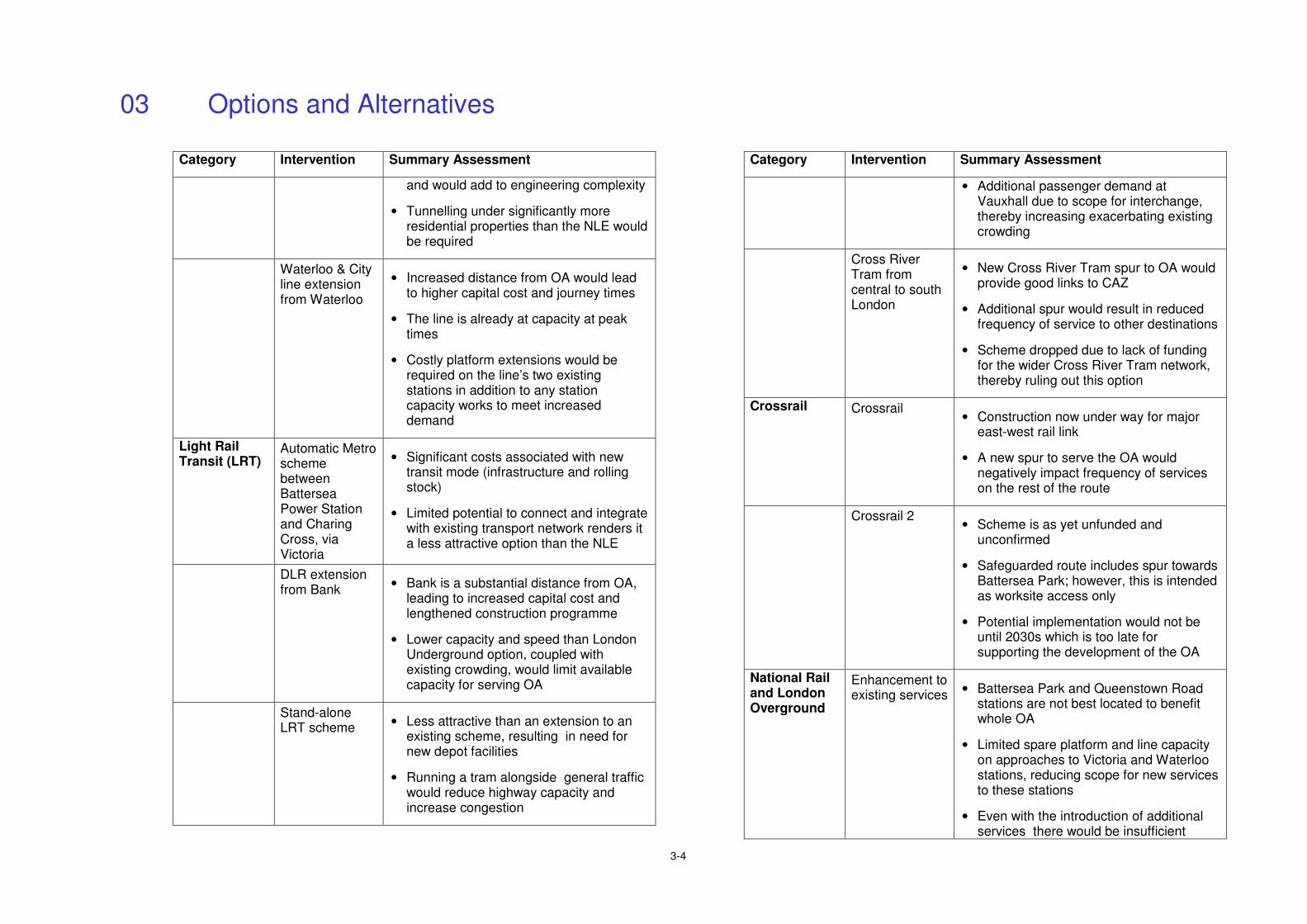
Category Intervention Summary Assessment
and would add to engineering complexity
• Tunnelling under significantly more residential properties than the NLE would be required
Waterloo & City line extension from Waterloo
• Increased distance from OA would lead to higher capital cost and journey times
• The line is already at capacity at peak times
• Costly platform extensions would be required on the line’s two existing stations in addition to any station capacity works to meet increased demand
Light Rail Transit (LRT)
Automatic Metro scheme between Battersea Power Station and Charing Cross, via Victoria
• Significant costs associated with new transit mode (infrastructure and rolling stock)
• Limited potential to connect and integrate with existing transport network renders it a less attractive option than the NLE
DLR extension from Bank
• Bank is a substantial distance from OA, leading to increased capital cost and lengthened construction programme
• Lower capacity and speed than London Underground option, coupled with existing crowding, would limit available capacity for serving OA
Stand-alone LRT scheme
• Less attractive than an extension to an existing scheme, resulting in need for new depot facilities
• Running a tram alongside general traffic would reduce highway capacity and increase congestion
Category Intervention Summary Assessment
• Additional passenger demand at Vauxhall due to scope for interchange, thereby increasing exacerbating existing crowding
Cross River Tram from central to south London
• New Cross River Tram spur to OA would provide good links to CAZ
• Additional spur would result in reduced frequency of service to other destinations
• Scheme dropped due to lack of funding for the wider Cross River Tram network, thereby ruling out this option
Crossrail Crossrail • Construction now under way for major
east-west rail link
• A new spur to serve the OA would negatively impact frequency of services on the rest of the route
Crossrail 2 • Scheme is as yet unfunded and
unconfirmed
• Safeguarded route includes spur towards Battersea Park; however, this is intended as worksite access only
• Potential implementation would not be until 2030s which is too late for supporting the development of the OA
National Rail and London Overground
Enhancement to existing services
• Battersea Park and Queenstown Road stations are not best located to benefit whole OA
• Limited spare platform and line capacity on approaches to Victoria and Waterloo stations, reducing scope for new services to these stations
• Even with the introduction of additional services there would be insufficient
03 Options and Alternatives
3-5
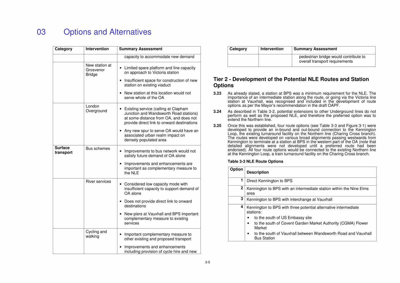
Category Intervention Summary Assessment
capacity to accommodate new demand
New station at Grosvenor Bridge
• Limited spare platform and line capacity on approach to Victoria station
• Insufficient space for construction of new station on existing viaduct
• New station at this location would not serve whole of the OA
London Overground
• Existing service (calling at Clapham Junction and Wandsworth Road stations) at some distance from OA, and does not provide direct link to onward destinations
• Any new spur to serve OA would have an associated urban realm impact on densely populated area
Surface transport
Bus schemes • Improvements to bus network would not
satisfy future demand of OA alone
• Improvements and enhancements are important as complementary measure to the NLE
River services
• Considered low capacity mode with insufficient capacity to support demand of OA alone
• Does not provide direct link to onward destinations
• New piers at Vauxhall and BPS important complementary measure to existing services
Cycling and walking
• Important complementary measure to other existing and proposed transport
• Improvements and enhancements including provision of cycle hire and new
Category Intervention Summary Assessment
pedestrian bridge would contribute to overall transport requirements
Tier 2 - Development of the Potential NLE Routes and Station Options
3.23 As already stated, a station at BPS was a minimum requirement for the NLE. The importance of an intermediate station along the route, or going via the Victoria line station at Vauxhall, was recognised and included in the development of route options, as per the Mayor’s recommendation in the draft OAPF.
3.24 As described in Table 3-2, potential extensions to other Underground lines do not perform as well as the proposed NLE, and therefore the preferred option was to extend the Northern line.
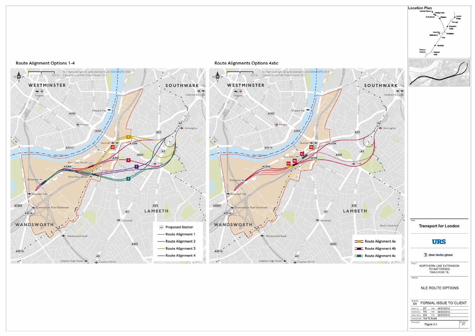
3.25 Once this was established, four route options (see Table 3-3 and Figure 3-1) were developed to provide an in-bound and out-bound connection to the Kennington Loop, the existing turnaround facility on the Northern line (Charing Cross branch). The routes were developed on various broad alignments passing westwards from Kennington to terminate at a station at BPS in the western part of the OA (note that detailed alignments were not developed until a preferred route had been endorsed). All four route options would be connected to the existing Northern line at the Kennington Loop, a train turnaround facility on the Charing Cross branch.
Table 3-3 NLE Route Options
Option Description
1 Direct Kennington to BPS
2 Kennington to BPS with an intermediate station within the Nine Elms area
3 Kennington to BPS with interchange at Vauxhall
4 Kennington to BPS with three potential alternative intermediate stations:
• to the south of US Embassy site
• to the south of Covent Garden Market Authority (CGMA) Flower Market
• to the south of Vauxhall between Wandsworth Road and Vauxhall Bus Station
03 Options and Alternatives
3-6
3.26 Although the selection of the NLE was formally acknowledged as the preferred modal option in the VNEB Transport Study, THUK had already considered that the NLE would be the likely optimal outcome. For this reason, in 2008 it appointed URS to undertake a Preliminary Environmental Assessment (PEA) (Ref. 3-5). This set out the key environmental issues brought about by the excavation, construction and operation of the NLE and provided a preliminary assessment of the anticipated environmental and socio-economic impacts of the three route options under consideration at that time. These impacts included:
• Noise & vibration;
• Air quality;
• Ground conditions & water resources;
• Waste;
• Ecology;
• Archaeology;
• Socio-economics; and
• Townscape & visual considerations.
3.27 The other main aim of the report was to highlight the likely differences between the environmental impacts of Route Options 1 to 3. Route Option 4 was developed at a later date; however, for the purpose of a high-level of comparison from an environmental perspective, this largely can be considered as a variation of Route Option 2, but placing the intermediate station to the north of the railway viaduct (see Figure 3-2).
3.28 This assessment complemented the engineering and transport feasibility work undertaken to determine the most appropriate route and led to the development of a preferred design for the NLE. The studies considered station and interchange options in addition to other necessary features such as ventilation intervention shafts.
3.29 Based on the information available at the time, the report concluded that:
• All options would provide significant socio-economic benefits such as employment generation and opportunities for local residents;
• A beneficial impact would arise from the removal of any contaminated material excavated during construction (e.g. station boxes, running tunnels, step plate junctions and ventilation and intervention shafts); and
• Slight beneficial impacts to air quality were anticipated due to the reduction in road traffic, although acknowledging that this would need to be investigated further to account for the major redevelopment of the VNEB OA.
3.30 Overall there would be a small number of localised, adverse residual effects arising as a result of the excavation, construction and operation of the any of the route options in terms of air quality, noise and vibration; ground conditions/water resources and archaeology.
3.31 The environmental impacts of Route Option 2 (and 4) were more beneficial due to the provision of an intermediate station. It was considered these options would offer a greater improvement in air quality due to a greater reduction in car and bus
trips as a result of modal shift than Route Options 1 and 3. By creating new stations (Route Options 2 and 4) there would be a greater opportunity to enhance the townscape around the intermediate station, and especially at the intermediate station location proposed for Route Option 2. More particularly, an intermediate station would significantly enhance the accessibility and regenerative benefits of the project by enabling the OA as a whole to benefit from enhanced infrastructure.
3.32 This environmental assessment, together with engineering, transport planning and other considerations informed an initial Route Options Appraisal carried out by SDG in 2010 (Ref 3-6). This concluded that Route Option 2 would be the best option to develop further.
3.33 TfL undertook an Updated Route Option Assessment in 2011 (Ref 3-7) as a ‘sense check’ on the earlier studies. The alternative routes were subject to review against TfL’s Strategic Assessment Framework and using the assessment framework provided by DfT’s Web Transport Analysis Guidance and New Approach to Appraisal (WebTAG and NATA). Route Option 2, with its intermediate station at Nine Elms (broadly at the corner of Wandsworth Road and Pascal Street) out-performed all other routes when assessed against a range of criteria. This option had the highest customer benefits (journey time and crowding) and policy compliance, and was also the most popular option at consultation.
3.34 Although Route Option 4 resembles Route Option 2 in some respects, by placing the intermediate station in the northern part of the OA it failed to confer the benefits of the NLE to the existing communities to the south and east of the OA to the same degree as Route Option 2. Route Option 4 has a less accessible location for its intermediate station than Route Option 2 and has lower journey time savings compared to Route Option 2.
3.35 Route Option 2 was expected to achieve the greatest patronage (and car transfer) and the greatest relief to crowding for existing users of the Underground. Additionally, Route Option 2 performed the strongest in terms of assessed transport benefits. Route Option 2 was also the most popular route with the public: in the public consultation of summer 2011 carried out jointly by THUK and TfL, Route Option 2 was chosen by 61% of respondents. It had also been the most popular option in the 2010 consultation undertaken by THUK.
3.36 Route Option 2 was also supported by the London Borough of Lambeth (LBL). An intermediate station in the Nine Elms vicinity had been considered to be a benefit to LBL during the preparation of the Transport Study. Route Option 2 was endorsed by the VNEB Strategy Board in October 2011, and was endorsed at the LBL Cabinet in January 2012.
3.37 As a result of this, Route Option 2 was carried forward to the next stage of development, where more detailed project and site specific aspects were considered.
Tier 3 – Project and Site Specific Options and Alternatives
3.38 In developing and reviewing the specific design for Route Option 2, a number of general assumptions and/or requirements had already been made, although as will be seen later in this chapter, some were subsequently revised. These included:
• two new stations, one at the BPS site and one at Nine Elms (broadly at the corner of Wandsworth Road and Pascal Street);
03 Options and Alternatives
3-7
• the broad alignment of the running tunnels;
• three permanent ventilation and intervention shafts required along the route (in addition to the provision within the stations themselves); and
• two temporary shafts in order to stabilise the ground and make the connection to the Kennington Loop.
3.39 To develop an optimal alignment, a number of aspects had to be considered, most importantly the feasibility of construction from an engineering perspective. The horizontal and vertical alignment of a running tunnel directly influences the quality of the train journey, and the most efficient route would be a straight line, which would be easier to construct and would also have operational advantages. However, the alignment did of course have to be developed in the context of existing conditions, such as piling from buildings, geological conditions and the existence of other infrastructure such as water pipes and other Underground tunnels, which limits the opportunities for straight lines, although these have been included where possible.
3.40 The following section summarises how the detail of these scheme aspects was developed in order to prepare a final scheme design. A notable aspect of this is the deletion of one of the proposed permanent shafts.
Station Alternatives
3.41 In developing the station designs, a number of general constraints and requirements must be satisfied, for example the need for the station boxes to accommodate certain train lengths. Cores are required to accommodate emergency escape provision to street level and are required at each end of the station together with ventilation for air conditioning and emergency smoke ventilation. From the start, both new stations for the NLE were developed to be step-free from street to train.
3.42 The need for appropriate temporary worksites and how best to manage the resultant potential adverse impacts, including environmental impacts, has been a consideration in developing options for the location of structures. A brief summary concerning the features at each site is provided in the sections below. Chapter 4: Description of the NLE describes the worksites in detail; the DAS (ES Volume II: Appendix M) sets out the reinstatement process, which will be done once the worksites are no longer needed.
Intermediate Station at Nine Elms
3.43 Several sites were considered in determining the final location and configuration of the station at Nine Elms. TfL’s Strategic Assessment Framework was applied to 11 locations in the Nine Elms area, resulting in four options being chosen for further investigation in a stage two assessment. All four of these options were situated on land just west of Wandsworth Road and north of Pascal Street. This area is divided into three adjoining plots of land occupied by Banham Security Ltd, CGMA and Sainsbury’s. The landowners and the local authority (LBL) were involved in these discussions and the development of the options.
3.44 The options for the form of the proposed station considered a number of physical constraints and opportunities, including:
• The station box must follow the east-west orientation of the proposed NLE alignment;
• The vertical alignment of the railway dictates a platform depth of approximately -18.5m OD (Ordnance Datum);
• The structure of the station box must include load-bearing provision for future over site development (OSD); and
• Proximity to Wandsworth Road (an ‘A’ Road with existing bus routes and stops) and the important CGMA access roads. Also considered was the station’s potential to accommodate and enhance the proposed public realm and access strategy for the area, including the provision of north-south pedestrian routes.
3.45 Also considered in appraising the options were: the pedestrian access points each option could provide; the location of ticket halls; and the potential lift and escalator configurations. There was very little difference between the options from an environmental perspective, although the number of items such as lifts, escalators and ticket halls clearly has an influence on energy usage. Potential construction and operational effects were considered in the selection of the proposed option (described in Chapter 4: Description of the NLE).
3.46 The evolution of the station design is described in the DAS (see ES Volume II: Appendix M) . It is worth noting here that the size of the station box increased from its original design to accommodate future train length, and also as result of the deletion of the Claylands Road shaft, which resulted in additional ventilation requirements at the station.
3.47 A number of options for the detailed configuration of the worksite in this area have been considered from the perspectives of engineering feasibility, environmental impact and others. It will prove necessary to relocate CGMA’s boiler house to accommodate the worksite and to take some of the space currently used for vehicle parking for this purpose; this has therefore been included in the Order as part of accommodation works and within the current limits of deviation. Further information about the worksite is provided in Chapter 4: Description of the NLE.
Terminus at Battersea Power Station
3.48 The location and design for the station within the BPS site considered the following constraints and opportunities:
• The adjacent main line railway to the west, Thames Water ring main to the east, and Battersea Park Road to the south;
• The east-west alignment of the incoming railway tunnels (from central London) and the outgoing overrun tunnels (towards Clapham Junction) limited the orientation of the station;
• Platform level would be at -13m OD - approximately 17m below street level;
• Proximity to sewer and UK Power Network tunnels;
• An operational requirement for a railway crossover box immediately outside the station;
• The structure of the station box must include load-bearing provision for the future OSD proposed as part of the BPS redevelopment; and
03 Options and Alternatives
3-8
• The need to integrate the station in order to optimise its relationship to the wider BPS Masterplan, as well as to serve adjacent areas.
3.49 The proposed station is described in Chapter 4: Description of the NLE. From an environmental perspective, the main issue of potential significance here is the energy usage impact from the number of lifts, escalators and ticket halls provided.
3.50 The station has been designed to function as a terminus and provide provision for any future extension.
3.51 As outlined above, Battersea station has from the start been located within the set parameters of the bigger BPS development, which places constraints on the worksite and how it fits with the other construction work in the vicinity. Excavated material from the site and tunnels (up to and beyond, but not including Nine Elms station) will be moved to the jetty at Battersea by conveyor belt and taken away by barge. In terms of environmental impact, this approach is preferred to using lorries. Additionally, TfL is liaising with other construction projects in the area to identify and capitalise on opportunities to minimise the overall impact by, for example, collaborating on materials removal or site sharing.
Permanent Shaft Alternatives
3.52 Permanent ventilation and intervention shafts are provided to ensure safety and comfort within tunnels once the underground railway is operating.
3.53 The ventilation shafts provide draught relief for the ‘piston effect’ of forced air flow in the tunnels from trains operating on the extension. The ventilation strategy is driven by the need to provide a safe system in the event of an incident in the running tunnels should there be a fire. The ventilation system whilst helping to maintain good air quality below ground also needs to provide the means to blow smoke away from passengers in the event of train evacuation. Ventilation and emergency access shafts are also provided within the stations.
3.54 The intervention strategy provides the means of access for the emergency services in the event of an emergency. Guidance concerning distance between shafts comes from the Office of Rail Regulation (ORR) Railway Safety Principles and Guidance (RSPG) Part 2a which indicates that an intervention and access point should usually be provided every kilometre along an underground railway. This guidance informed the development of an intermediate shaft in the vicinity of Claylands Road.
3.55 The shafts can also be used to connect the railway with a ground level traction power source for train operation if required. The location of the shaft for this purpose is dictated by the limited distance that a low voltage power supply can travel. An initial power supply simulation indicated that a sub-station could be required at a point between Kennington and the proposed Nine Elms intermediate station and provision for this has been made in the design.
Shafts Required for the NLE
3.56 The initial engineering design suggested that the following shafts (described from east to west) would be required to construct and service the new tunnels proposed for the NLE:
• Two (temporary) grouting shafts near the Kennington Loop;
• Two (permanent) intervention and ventilation shafts (in the Kennington Park and Kennington Green areas) which would also allow the dismantling and removal of the Tunnel Boring Machines (TBMs); and
• A combined intervention and ventilation shaft and traction substation where the running tunnels converge in the Claylands Road area (a permanent shaft).
Establishment of Preferred Shaft Sites
3.57 The function of the particular shafts drives the broad location of each shaft, and at each broad location a range of alternative sites were identified and appraised in terms of a number of criteria, to establish the preferred sites, including:
• Constructability and availability of a suitable worksite;
• Efficiency of ventilation and distance of the shaft from centre line of route alignment;
• Acceptability to the London Fire and Emergency Planning Authority (LFEPA) in terms of the distance between the above-ground access at the shafts to running tunnels;
• Amount of temporary or permanent land take and property acquisition;
• Amount of disruption to trees and ecology;
• Distance to the closest sensitive receptors (e.g. residential properties) to avoid construction and operational air quality and noise impacts;
• The presence of heritage and townscape constraints (e.g. Listed buildings and Conservation Areas); and
• Suitable parking space in proximity for maintenance and emergency vehicle parking.
3.58 Shafts need to be directly above, or very close to, the running tunnels. Each permanent shaft also requires an above-ground structure called a head house, either directly above the shaft or close by (linked to the shaft via a subsurface adit).
3.59 In the case of the shafts at Kennington Park and Kennington Green, these general locations are indicated by the need to place the shaft as close as practicable to the junction where the existing and new railway tunnels will meet.
3.60 The development and consideration of alternatives for the permanent and temporary shafts is summarised below. In all cases, a ‘long list’ of potential sites for each of the shaft types was drawn up (including a number of suggestions made by residents) and these were appraised against the criteria to establish an overall preference.
Northbound Permanent Shaft, Kennington Green
3.61 With these constraints in mind, and the need for the shaft to be above the northbound tunnel, several potential options were developed, all of which place the worksite on the Green. The nearby Beefeater gin distillery (which comprises buildings in a compound) was identified as a potential site for the head house, as was the Green itself. The potential configurations identified were:
03 Options and Alternatives
3-9
1. A below ground shaft structure located in the distillery forecourt, along with the head house above it;
2. A below ground shaft structure located on the Green with the head house above;
3. A below ground shaft structure located on the Green and access provision above, with ventilation provision in the distillery forecourt; and
4. A below ground shaft structure located on the Green with the head house in the distillery forecourt.
3.62 In terms of operational considerations, all reasonable potential operational issues associated with the two uses (the distillery and the head house) were taken into account and it was concluded that the head house had been designed in a manner that would manage and mitigate all likely and reasonably potential hazards, the risk of which was low.
3.63 A key consideration in appraising the sites was the anticipated environmental impacts. Dealing with each option in turn, the first configuration option located the shaft and head house entirely within the distillery, but was not located directly above the northbound running tunnel and any realignment would lead to a sub-optimal route alignment that would have a number of wide ranging environmental and operational constraints, such as increased operational noise and reduced train speeds.
3.64 The second option would result in the permanent loss of part of the Green and was anticipated to lead to substantial harm to the Conservation Area and its townscape value. The third option was also expected to result in similar effects and was also not considered appropriate.
3.65 The fourth option would avoid the permanent loss of any part of the Green and would allow the optimum route alignment to be retained, thereby minimising environmental impacts across the wider route during operation.
3.66 The public consultation in summer 2011 (Ref. 3-8) consulted on options two and four, both of which placed the shaft on the southern corner of the Green, with either the head house above or within the yard of the Distillery. Option four was highlighted as the most preferred (43% of respondents, with only 6% preferring the Green, and 38% having no preference). Option four was subsequently incorporated into the developing scheme design, and further engagement with local groups regarding the restoration of the Green was undertaken.
3.67 The proposed worksite comprises all of the Green. It has been developed to operate in a way that minimises the impact of the work on the best of the existing trees. The head house is not on the Green and, as described in Chapter 4: Description of the NLE and in the DAS (ES Volume II: Appendix M), reinstatement and improvement works are proposed which have been informed by public consultation and engagement with LB Lambeth, English Heritage and community and residents groups.
3.68 The impacts of the worksite on the local road network are set out in Chapter 6: Traffic and Transport. In terms of disruption to the distillery, while part of the distillery is within the construction site boundary, there will be no disruption in
terms of access to the distillery; the access gates will be moved a few metres northwards as part of preparatory works.
3.69 During TfL’s review of the scheme in 2012 and further engagement with stakeholders, including the distillery owners, potential further options for this shaft were considered, as follows:
• Shaft in south-western corner of the Green, head house at brownfield site to the northwest of the Green, and a variation with the shaft in north-western corner of the Green (worksite on the Green for both options);
• Shaft in south-western corner of the Green, head house in the car park of the Lycee apartment building opposite (worksite on the Green), and a variation which places both the shaft and the head house in the Lycee building car park (worksite also in the car park);
• Shaft at 379 Kennington Road (commercial premises) with surrounding buildings, head house and worksite at this location;
• Shaft and worksite in Green, and head house at site of extension to 356 Kennington Road;
• Shaft at 373 Kennington Road (commercial premises), with head house and shaft at this location;
• Shaft, head house and worksite in Green (which was consulted on as described above);
• Shaft, head house and worksite to the rear of Kennington station, requiring some surrounding residential property; and
• Shaft at telephone exchange on Kennington Park Road (opposite Kennington station), with intervention point at station.
3.70 These potential alternatives were considered from a range of perspectives, including their environmental impacts (such as noise impacts on residents), their effect on local businesses and their ability to meet the functional and locational requirements for a shaft. Temporary (construction phase) and operational effects were taken into account. The need to acquire property and the potential for the design of the new structure to preserve or enhance the existing situation were also considered. Taking each consideration into account it was concluded that each of these alternative options performed worse overall than the selected option and current proposal.
Southbound Permanent Shaft, Kennington Park
3.71 Three options were developed for the southbound ventilation shaft and corresponding head house. Due to the tunnel alignment – all three located the shaft in the north-eastern corner of Kennington Park (which is within a Conservation Area): The head house and ventilation options were as follows:
• Head house located immediately above the shaft;
• Escape and ventilation provision located in/alongside the adjacent Kennington Park Lodge; and
• Escape provision located immediately above the shaft and the ventilation provision located in/next to the adjacent Kennington Park Lodge.
03 Options and Alternatives
3-10
3.72 The second option would situate the shaft directly above the southbound running tunnel and avoid above ground construction in this location which would entail the permanent loss of amenity land from the historic Kennington Park. Although Kennington Park Lodge currently houses a community facility the head house could be constructed in such a way as to include a well-designed replacement facility, subject to the views of LBL and local amenity and resident groups (who have been engaged in the development of potential options). The environmental effects of construction would be similar under all options, with a dog walking area within the park requiring temporary relocation.
3.73 The first two Park options were included in the public consultation of summer 2011 and placing both the shaft and the head house in the Lodge was the preferred option (27% of respondents compared to 12% for the Park option (40% had no opinion). As for the Green, this preferred option was taken forward and local engagement on design and restoration was undertaken.
3.74 Here the worksite will encompass the site of the lodge and then extend parallel to Kennington Park Place, ending just before the junction with Kennington Park Road. Given the current use of the lodge as a community facility, the reinstatement work will seek to improve the facilities and enhance the local ecology and biodiversity through, for example, planting as part of the landscaping strategy (see DAS, ES Volume II: Appendix M).
3.75 A further development at this shaft has been the need to incorporate the traction substation. This is as a consequence of the deletion of the shaft at Claylands Road, which is described below.
3.76 During TfL’s review of the scheme in 2012 and further engagement with stakeholders including local residents, potential further options for this shaft were considered, as follows:
• Shaft, head house and worksite within the Veolia compound in Kennington Park;
• Shaft in the Park, head house and worksite within the Veolia compound;
• Shaft, head house and worksite at Kennington Station, requiring acquisition of some surrounding commercial and residential property (also considered as an alternative for Kennington Green);
• Shaft at Oval Green (traffic island opposite Oval station), head house and worksite in the Park;
• Shaft, head house and worksite in the Park (consulted on in 2011); and
• Shaft, head house and worksite in telephone exchange on Kennington Park Road, to the south of Kennington station.
3.77 In the case of locating the shaft, head house and worksite in the Veolia compound, this option had been considered earlier in scheme development and had not been pursued in the first instance due to the need to move the tunnel alignment and the difficulty of relocating the current functions of the site, and these and other factors mean that it continues to perform worse than the current proposal.
3.78 As was the case for the potential alternatives for the shaft at Kennington Green, all these potential alternatives were considered from a range of perspectives, including their environmental impacts (such as noise impacts on residents), their effect on local businesses and their ability to meet the functional and locational
requirements for a shaft. Temporary (construction phase) and operational effects were taken into account. The need to acquire property and the potential for the design of the new structure to preserve or enhance the existing situation were also considered. It was concluded that each of these options perform worse overall than the selected option and current proposal.
Claylands Road Intervention and Ventilation Shaft
3.79 As indicated above, the need for an intervention shaft in this broad location was indicated by guidance on the usual distance between intervention points. With this in mind, a number of potential sites for combined ventilation and intervention shaft options were considered in this area on the basis of their constructability, function/purpose, and potential environmental impacts.
3.80 Initially, the site in the centre of the main Green at Claylands Road with the associated head house and substation immediately above the top of the shaft was preferred as it would provide the simplest arrangement to accommodate all the necessary features of this facility and would offer the best means of access for the emergency services.
3.81 However, the public consultation of summer 2011 indicated a preference for the shaft to be located at the garages facing Cottingham Road, removing the need for a permanent structure within the centre of the Green (although the Green would remain as a worksite).
Deletion of Claylands Road Shaft
3.82 Following feedback from local residents and businesses who were concerned about the impact of a shaft at this location, TfL undertook work to determine whether it could be moved or deleted. This work eventually led to the removal of this shaft. This was enabled by the development of an alternative fire and evacuation operational strategy, which required an increase to the internal diameter of the running tunnels in order to accommodate a walkway. The other functions of this shaft would be achieved by modifications to the proposed permanent shafts at Kennington Park and Kennington Green, as well as at Nine Elms station.
Temporary Shafts
3.83 Temporary shafts are often required during the construction of an underground railway in order to allow work to stabilise the ground (through the injection of grout) in certain geological conditions and with certain construction methodologies.
3.84 The majority of the NLE running tunnels would be constructed using TBMs. This methodology involves installing precast concrete tunnel lining once the TBM has excavated material, which allows for effective ‘propping’ of the ground above and surrounding the tunnel (and reduced ground settlement). It is proposed that the two new running tunnels are connected to the Kennington Loop by means of step plate junctions.
3.85 A consideration of the engineering feasibility for this approach indicated that the TBM methodology would require ground stabilisation works in this area to minimise ground movement and the risk of settlement damage to properties, it was proposed that grouting work be carried out using two temporary shafts (one for the northbound tunnel, one for the southbound). The broad location of each shaft is
03 Options and Alternatives
3-11
determined by the maximum distance (radius) they can be placed from the connection. They are also needed to construct a TBM reception chamber i.e. a section of prebuilt tunnel larger than the TBM to enable the TBM to be dismantled for removal from the permanent shaft.
3.86 A potential other means of connecting the extension to the Kennington Loop was identified during the review of the scheme in 2012 which would not require temporary shafts. Instead, underground ‘gallery tunnels’ would be constructed in order to undertake the ground treatment works. At the time of submitting the TWAO application, TfL is not in a position to be able to make a decision with regard to the preferred approach and therefore both methods are included in the application.
Temporary Shaft Alternatives
3.87 As for the permanent shafts, a number of general constraints apply in determining the broad location of the temporary shafts (as described above), although for temporary shafts these impacts will be of limited duration once they have been constructed.
3.88 The location of the two temporary shafts was subject to consultation with local residents and businesses in autumn 2011. To prepare the consultation, a number of potential sites were identified for each of the ‘north’ and ‘south’ locations based on factors including proximity to the Loop, availability of suitable land and environmental impacts. Two further sites were added because they were suggested by residents during engagement prior to the start of the consultation: the White Bear pub garden and the Bishop’s House Children’s Centre. However, as was stated in the consultation leaflet, the eventual selection of a recommended site for each shaft would be informed by further technical work as well as the results of the consultation itself. For this local consultation, 2,500 questionnaires were distributed and 248 responses received.
3.89 Four northbound grouting shaft options were consulted on, as follows:
• Ravensdon Street;
• Stannary Street between Radcot Street and Kennington Park Road;
• Radcot Street; and
• White Bear pub garden.
3.90 Three southbound grouting shaft options were consulted on as follows:
• Bishops House Children’s centre;
• Harmsworth Street; and
• De Laune Street.
3.91 The results of the consultation indicated that for the northbound shaft, the White Bear pub garden was the most popular (43% of respondents) and for the southbound shaft, the Children’s Centre was the most popular (30% of respondents). These results were considered as part of an overall appraisal of the options, which TfL published in early 2012 (Ref. 3-9). The appraisal considered both ecological and environmental impacts including, for example, trees and noise and air quality.
3.92 As a result of this appraisal, the option at Radcot Street was recommended as the option to be taken forward, mainly because it would offer the best opportunity for construction of the grouting shafts without disrupting private land (the White Bear pub garden would, for example, be more disruptive). The Radcot Street site would entail the least disruption to the road network and services during construction. The temporary environmental effects would be similar for each option and, whilst disruptive during construction for aspects such as noise and air quality, those were considered to be controllable through good site practice. Some roadside car parking spaces would need to be temporarily taken out of use for the construction period.
3.93 For the southbound shaft, the appraisal identified the option at Harmsworth Street as the recommended site. This option would avoid the need for a direct intervention at the nursery school and avoid having construction activity there. It would be located between the gable ends of residential property rather than directly in front of windows and gardens, which would help to shield noise during construction in addition to those effects being controlled through good site practices. The site would also provide the least disruption to the road network, avoiding the need to take possession of De Laune Street itself that provides the main access into the residential area, although some roadside car parking spaces would need to be temporarily taken out of use for the construction period.
Consultation
3.94 Consultation with stakeholders (such as the London boroughs of Lambeth, Southwark and Wandsworth, statutory consultees, and major landowners), and the public has been critical in developing and assessing the options for and alternatives to the NLE.
3.95 The first phase of consultation led by THUK on the route options and sites for the project was held in 2010 and was subsequently re-run in 2011, this time jointly by TfL, the Mayor and THUK. This consultation sought views on the four route options and the potential location of permanent shafts. A further, more localised consultation was held in autumn 2011 regarding potential sites for the temporary shafts. Information on how these results informed the selection of preferred options has been set out in the relevant sections of this chapter.
3.96 In June 2012 a leaflet was delivered to addresses in the area of the proposed route. It comprised an update on the scheme’s progress and provided an opportunity to register for news and comment via email.
3.97 A further public consultation ran from 7 November to 30 December 2012, seeking views on the overall proposal as well as on specific aspects of the scheme such as head house design and restoration at the permanent shaft sites. TfL has published a report on this consultation on its website (Ref. 3-10).
How the NLE Fulfils the Aims of the Mayor’s Transport Strategy
3.98 In particular, the NLE is intended to meet a number of the goals for transport in London set out in the Mayor’s Transport Strategy (MTS) (2010). The MTS sets six goals; while the sixth is specific to the 2012 Games, the others are relevant as secondary aims of the NLE. Those goals are enumerated below:
• Support economic development and population growth;
03 Options and Alternatives
3-12
• Enhance the quality of life for all Londoners;
• Improve the safety and security of all Londoners;
• Improve transport opportunities for all Londoners; and
• Reduce transport’s contribution to climate change and improve its resilience.
3.99 A Concise Statement of Aims has been prepared by TfL and submitted as part of the TWAO application. In addition to stating the primary aim of the NLE, it sets out how the NLE will help to achieve the aims of the MTS. This is as follows:
• Support economic development and population growth - By enabling the sustainable regeneration and development of the VNEB OA, the NLE will catalyse the creation of 16,000 new homes and 20,000-25,000 new jobs. In addition, it will enhance access to employment for local people in the surrounding area and integrate the VNEB OA with the remainder of central London.
• Enhance the quality of life for all Londoners - As part of a wider package of transport and urban realm improvements, the NLE will bring economic and accessibility benefits to a wide area, including the existing and new communities around Nine Elms station.
• Improve the safety and security of all Londoners - The Underground is a safe and secure transport mode whilst stations provide safe and attractive meeting-points; the new stations at Battersea and Nine Elms will be modern, well-designed landmarks which will be integrated with high quality urban realm, benefiting new and existing communities in the area.
• Improve transport opportunities for all Londoners - The NLE will transform accessibility across the VNEB OA and deliver standards available elsewhere in central London, assisting and complementing London’s transport network. Both new stations will be step-free from street to train and will significantly enhance transport accessibility to all by creating new high quality access points to the Underground network.
• Reduce transport’s contribution to climate change and improve its resilience - The Underground is a sustainable transport mode and the NLE will be constructed to the most up-to-date design and environmental standards. The NLE will contribute to making the area more typical of central London in terms of providing alternatives to car travel. (Chapter 16: Climate Change Adaptation and Mitigation).
References
Ref. 3-1 DfT (2006); Transport and Works (Applications and Objections Procedure) (England and Wales) Rules
Ref. 3-2 Department for Communities and Local Government (DCLG) (2011); Town and Country Planning (Environmental Impact Assessment) Regulations (2011)
Ref. 3-3 Steer Davies Gleave (2008); Nine Elms and North East Battersea Outline Feasibility Studies and Business Case for Tram and Tube options, SDG on behalf of Treasury Holdings, February 2008
Ref. 3-4 Sinclair Knight Merz (2009); VNEB OA Transport Study Ref. 3-5 URS Corporation Limited (2008); Preliminary Environmental Assessment Ref. 3-6 SDG (2010); Initial Route Options Appraisal Ref. 3-7 TfL (2011); Updated Route Option Assessment Ref. 3-8 TfL (2011); Report on the Consultation and Update on the Proposal Ref. 3-9 TFL (2012); Report on Consultation and Initial Appraisal of Options [temporary
shaft sites] Ref. 3-10 TfL (2013); Report on Consultation [Nov-Dec 2012]

[Type text]
04 Description of the NLE
Environmental Statement
Volume I

04 Description of the Northern Line Extension
4-1
Introduction
4.1 As described in Chapter 3: Options and Alternatives, a broad range of strategic and project level options have been considered by Transport for London (TfL) in order to best serve the transport requirements of the regeneration of the Vauxhall, Nine Elms and Battersea Opportunity Area (VNEB OA). This chapter provides a description of the Northern Line Extension (NLE), and comprises:
• A scheme description overview;
• Construction Assumptions and Description of Works;
− A summary of the order of main construction activities, including the outline programme;
− Battersea station worksite activities;
− Nine Elms worksite activities (plus ancillary works);
− Construction of the running tunnels, cross passages and step plate junctions;
− Description of the two potential construction options at the eastern end;
− Activities associated with the permanent and temporary shafts and worksites under each construction options (plus ancillary works);
− Construction of Kennington station cross passages; and
− Overview of Code of Construction Practice (CoCP) and how materials are managed.
• A summary of the operational NLE once completed including;
− Battersea station and illustrative public realm;
− Nine Elms station and illustrative public realm;
− Above ground elements at the permanent shaft sites (e.g. head houses and illustrative public realm);
− Train operations; and
− Stations’ operations and ventilation overview.
4.2 This Environmental Impact Assessment (EIA) has been based on the most likely alignment of the NLE as would be permitted by the terms of the proposed Transport and Works Act Order (TWAO) and the Deposited Plans and Sections, but it has also taken into account the power in the draft Order to deviate laterally within the limits shown on the Deposited Plans and vertically within the limits shown on the Deposited Sections and in accordance with article 5 of the draft Order. This chapter provides a selection of plans and figures relating to the NLE, used for the purposes of assessing the potential significant environmental effects. A complete schedule of figures is provided at the beginning of this Environmental Statement (ES).
4.3 Further details on the temporary and permanent works, architectural drawings and design information is provided in the following documents, that accompany the TWAO application and application for the Planning Direction:
• Deposited Plans and Sections;
• Planning Direction Application including Drawings;
• Conservation Area Consent Application including Drawings; and
• Design and Access Statement (see ES Volume II: Appendix M).
4.4 The following documents associated with this chapter are appended in ES Volume II:
• Materials Management Strategy (see ES Volume II: Appendix B);
• Project Sustainability Appraisal Report (see ES Volume II: Appendix O); and
• Outline Energy Strategy (see ES Volume II: Appendix O).
4.5 The TWAO application will be accompanied by a request for a Planning Direction for deemed planning permission for all works that may be built under the Order. Some details, such as the scale and external appearance of stations, will be subsequently approved by the Local Planning Authorities though discharge of the relevant Planning Direction Conditions.
Scheme Description Overview
4.6 The NLE works comprise the construction of an underground railway to form an extension of the Northern line (Charing Cross branch) from Kennington to Battersea. It will diverge from the existing railway south of Kennington station from a section of track used by terminating trains (known as the Kennington Loop) and will comprise the following:
• Railway approximately 3,150 metres long northbound and approximately 3,250 metres long southbound including overrun / stabling tunnels west of the terminus at Battersea, a crossover east of the terminus and junctions serving each of the tunnels to link with the existing railway at the Kennington Loop;
• A terminus at a new station at Battersea located between Battersea Park Road and the Battersea Power Station (BPS) and an intermediate station at Nine Elms west of Wandsworth Road and north of Pascal Street, both providing step-free access from trains to street level;
• Intervention and ventilation shafts with head houses at Kennington Green and Kennington Park to provide emergency access, tunnel ventilation and smoke control; and
• Ancillary and mitigation works within the limits of deviation including (but not limited to) providing power supply, additional cross passages at platform level at Kennington station and works related to highways, footways and utilities.
4.7 The NLE works also include:
• Accommodation works for affected landowners / occupiers including, but not limited to:
− temporary facilities for Battersea Dogs and Cats Home and Covent Garden Market Authority (CGMA);
− temporary and permanent facilities for occupiers of the Park Lodge at Kennington Park; and
− the installation of a water tank and other accommodation works for the benefit of the Beefeater Gin Distillery.
04 Description of the Northern Line Extension
4-2
• Temporary works including worksites at the locations of the proposed stations and shafts / head houses, temporary shafts at Radcot Street and Harmsworth Street and a temporary conveyor and associated alterations to the jetty at the BPS to facilitate the transfer of material onto barges.
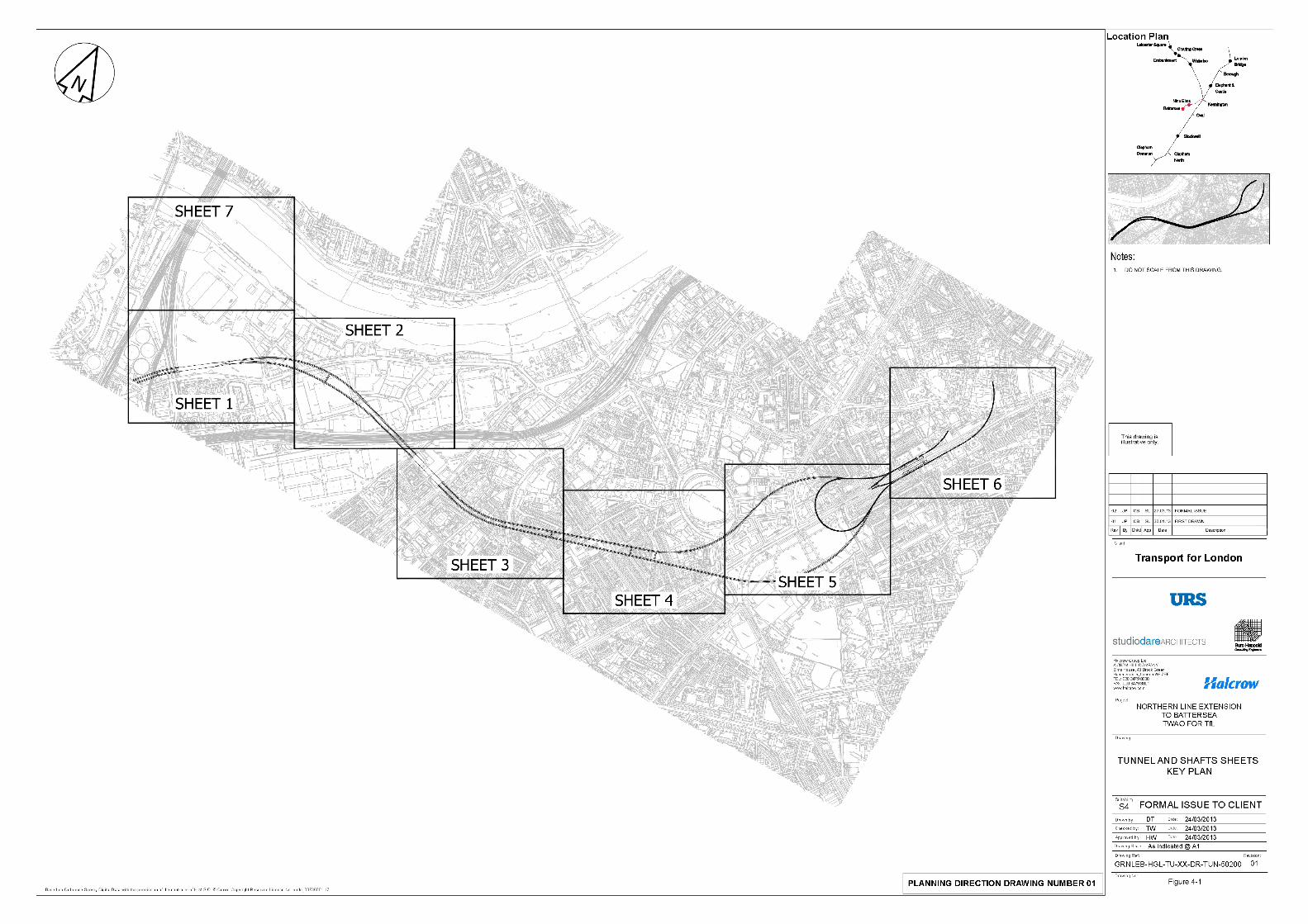
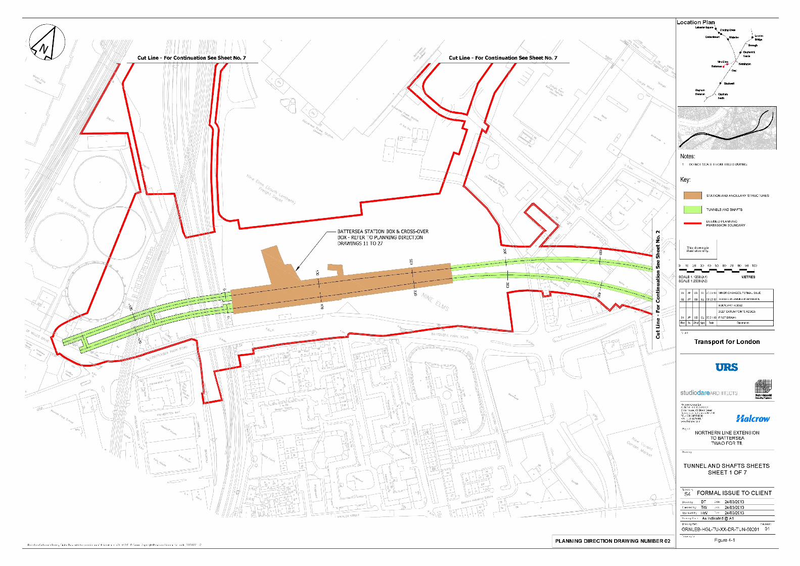
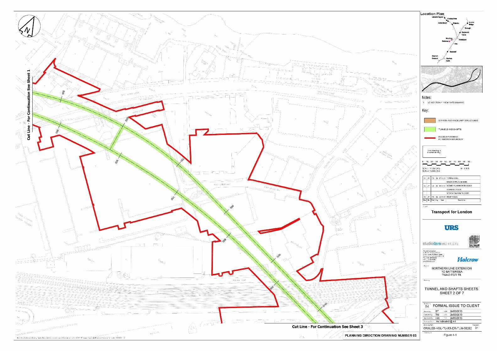
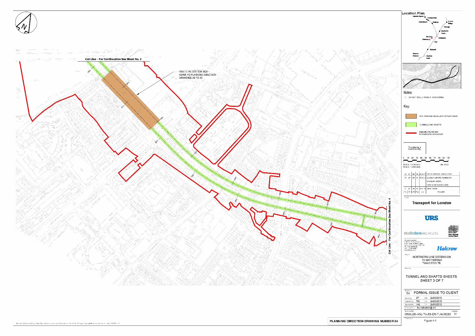
4.8 Figure 4-1 provides an overview plan of the route and the limits of deviation, within which the powers to construct and operate the NLE are proposed to apply.
Construction Assumptions
4.9 This section describes the approach to construction which has been assumed for the purposes of the EIA. The construction programme, layouts and working methods are illustrative and do not form part of the project for which consent is sought. The methods, order and timing of the construction works outlined herewith are illustrative, but representative of a practicable method to construct the works and are considered suitable for this assessment.
4.10 Although the programme, layouts and working methods described are illustrative, they represent what is considered to be the likely approach, given the existing site constraints, the adjacent land uses and the construction requirements. This section describes only the main activities with the focus on those that are relevant for the assessment of environmental effects.
4.11 Although being assessed in this ES, the timing of the works at the Beefeater Gin Distillery site (for the water tank), Kennington station cross passages, and at Nine Elms (the CGMA boiler house and new pedestrian walkway) are not connected with the main construction works and will involve only limited activities. They are expected to be constructed early in the overall construction programme and result in negligible levels of construction traffic and workers.
4.12 In addition, in some cases certain details, such as the scale and external appearance of stations and landscape, will be subsequently approved by the Local Planning Authorities through the discharge of relevant Planning Conditions. These elements are specified where appropriate, however this ES assesses the likely effects arising from them, meaning that a further EIA is not required once these details are finalised and planning permission has been sought.
4.13 The assumed construction programme is described first, followed by typical construction activities for each component of the project.
Indicative Construction Programme
4.14 The construction of the NLE is expected to be carried out in the following broad sequence of activities:
• Enabling works and excavation of two station boxes at the worksites of Battersea and Nine Elms stations;
• Launching of two tunnel boring machines (TBMs) from the Battersea worksite that will follow the proposed route, via Nine Elms to two ‘permanent shafts’ at Kennington Park and Kennington Green worksites;
• Here, two construction options are being considered, one of which will require the construction of ‘temporary shafts’ at Radcot Street and Harmsworth Street worksites in order to enable the safe construction of the step plate junctions to
connect with the existing Kennington Loop and build a reception chamber to enable the TBMs to be dismantled;
• At a similar time to this, further works will occur at the station and permanent shaft worksites that involve the construction of the above ground elements (i.e. stations and head houses); and
• The commissioning of the NLE will then occur, followed by commencement of passenger services.
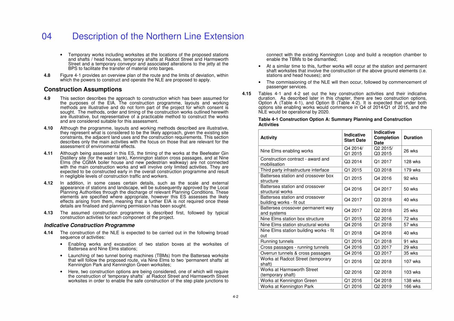
4.15 Tables 4-1 and 4-2 set out the key construction activities and their indicative duration. As described later in this chapter, there are two construction options, Option A (Table 4-1), and Option B (Table 4-2). It is expected that under both options site enabling works would commence in Q4 of 2014/Q1 of 2015, and the NLE would be operational by 2020.
Table 4-1 Construction Option A: Summary Planning and Construction Activities
Activity Indicative Start Date
Indicative Completion Date
Duration
Nine Elms enabling works Q4 2014/ Q1 2015
Q2 2015/ Q3 2015
26 wks
Construction contract - award and mobilisation
Q3 2014 Q1 2017 128 wks
Third party infrastructure interface Q1 2015 Q3 2018 179 wks
Battersea station and crossover box structure
Q1 2015 Q4 2016 92 wks
Battersea station and crossover structural works
Q4 2016 Q4 2017 50 wks
Battersea station and crossover building works - fit out
Q4 2017 Q3 2018 40 wks
Battersea crossover permanent way and systems
Q4 2017 Q2 2018 25 wks
Nine Elms station box structure Q1 2015 Q2 2016 72 wks
Nine Elms station structural works Q4 2016 Q1 2018 57 wks
Nine Elms station building works - fit out
Q1 2018 Q4 2018 40 wks
Running tunnels Q1 2016 Q1 2018 91 wks
Cross passages - running tunnels Q4 2016 Q3 2017 29 wks
Overrun tunnels & cross passages Q4 2016 Q3 2017 35 wks
Works at Radcot Street (temporary shaft)
Q1 2016 Q2 2018 107 wks
Works at Harmsworth Street (temporary shaft)
Q2 2016 Q2 2018 103 wks
Works at Kennington Green Q1 2016 Q4 2018 138 wks
Works at Kennington Park Q1 2016 Q2 2019 166 wks
04 Description of the Northern Line Extension
4-3
Activity Indicative Start Date
Indicative Completion Date
Duration
Step plate junction 1 northbound Q3 2016 Q4 2017 69 wks
Step plate junction 2 southbound Q3 2016 Q1 2018 66 wks
Running tunnels permanent way and systems
Q1 2018 Q3 2018 28 wks
Kennington Loop turnout 1 (step plate junction 1 northbound)
Q2 2018 Q3 2018 12 wks
Kennington Loop turnout 2 (step plate junction 2 southbound)
Q2 2018 Q3 2018 12 wks
Commissioning and handover Q2 2019 Q1 2021 88 wks
Commencement of passenger services Q1 2020 - -
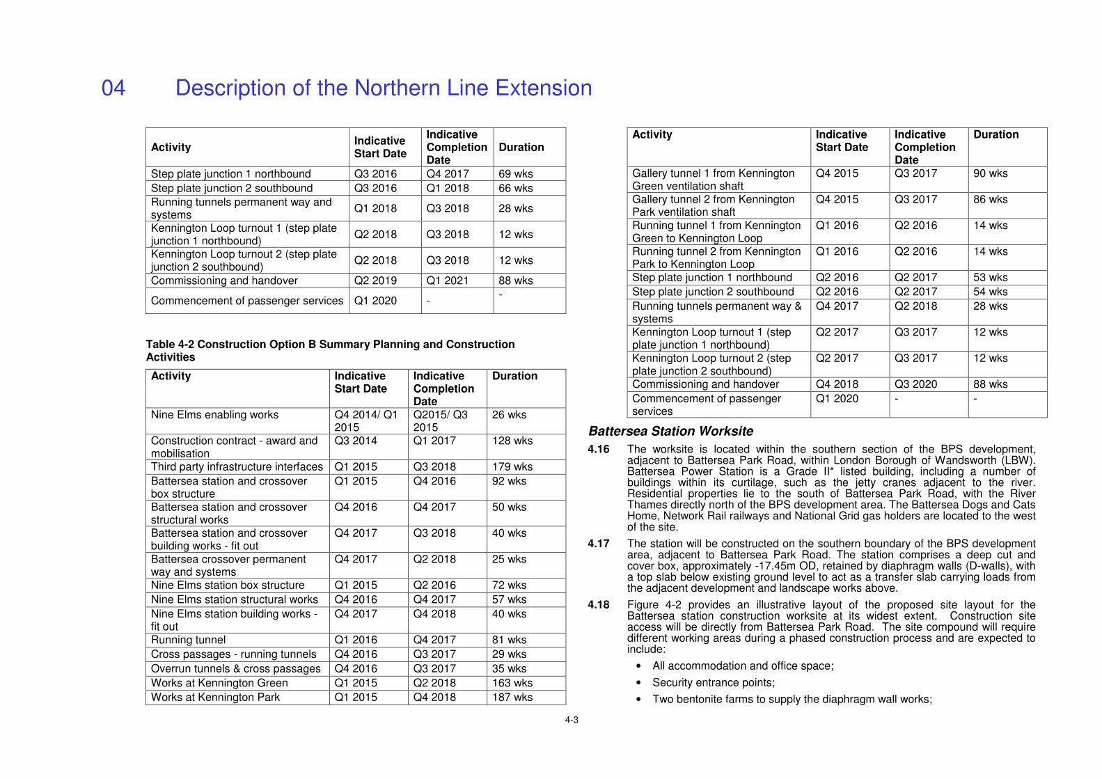
Table 4-2 Construction Option B Summary Planning and Construction Activities
Activity Indicative Start Date
Indicative Completion Date
Duration
Nine Elms enabling works Q4 2014/ Q1 2015
Q2015/ Q3 2015
26 wks
Construction contract - award and mobilisation
Q3 2014 Q1 2017 128 wks
Third party infrastructure interfaces Q1 2015 Q3 2018 179 wks
Battersea station and crossover box structure
Q1 2015 Q4 2016 92 wks
Battersea station and crossover structural works
Q4 2016 Q4 2017 50 wks
Battersea station and crossover building works - fit out
Q4 2017 Q3 2018 40 wks
Battersea crossover permanent way and systems
Q4 2017 Q2 2018 25 wks
Nine Elms station box structure Q1 2015 Q2 2016 72 wks
Nine Elms station structural works Q4 2016 Q4 2017 57 wks
Nine Elms station building works - fit out
Q4 2017 Q4 2018 40 wks
Running tunnel Q1 2016 Q4 2017 81 wks
Cross passages - running tunnels Q4 2016 Q3 2017 29 wks
Overrun tunnels & cross passages Q4 2016 Q3 2017 35 wks
Works at Kennington Green Q1 2015 Q2 2018 163 wks
Works at Kennington Park Q1 2015 Q4 2018 187 wks
Activity Indicative Start Date
Indicative Completion Date
Duration
Gallery tunnel 1 from Kennington Green ventilation shaft
Q4 2015 Q3 2017 90 wks
Gallery tunnel 2 from Kennington Park ventilation shaft
Q4 2015 Q3 2017 86 wks
Running tunnel 1 from Kennington Green to Kennington Loop
Q1 2016 Q2 2016 14 wks
Running tunnel 2 from Kennington Park to Kennington Loop
Q1 2016 Q2 2016 14 wks
Step plate junction 1 northbound Q2 2016 Q2 2017 53 wks
Step plate junction 2 southbound Q2 2016 Q2 2017 54 wks
Running tunnels permanent way & systems
Q4 2017 Q2 2018 28 wks
Kennington Loop turnout 1 (step plate junction 1 northbound)
Q2 2017 Q3 2017 12 wks
Kennington Loop turnout 2 (step plate junction 2 southbound)
Q2 2017 Q3 2017 12 wks
Commissioning and handover Q4 2018 Q3 2020 88 wks
Commencement of passenger services
Q1 2020 - -
Battersea Station Worksite
4.16 The worksite is located within the southern section of the BPS development, adjacent to Battersea Park Road, within London Borough of Wandsworth (LBW). Battersea Power Station is a Grade II* listed building, including a number of buildings within its curtilage, such as the jetty cranes adjacent to the river. Residential properties lie to the south of Battersea Park Road, with the River Thames directly north of the BPS development area. The Battersea Dogs and Cats Home, Network Rail railways and National Grid gas holders are located to the west of the site.
4.17 The station will be constructed on the southern boundary of the BPS development area, adjacent to Battersea Park Road. The station comprises a deep cut and cover box, approximately -17.45m OD, retained by diaphragm walls (D-walls), with a top slab below existing ground level to act as a transfer slab carrying loads from the adjacent development and landscape works above.
4.18 Figure 4-2 provides an illustrative layout of the proposed site layout for the Battersea station construction worksite at its widest extent. Construction site access will be directly from Battersea Park Road. The site compound will require different working areas during a phased construction process and are expected to include:
• All accommodation and office space;
• Security entrance points;
• Two bentonite farms to supply the diaphragm wall works;
04 Description of the Northern Line Extension
4-4
• Materials laydown area;
• Materials storage areas;
• Crawler cranes to support the diaphragm wall works;
• Tower cranes to support the in-situ concrete works;
• Hoist facilities to support the station fit-out works; and
• Adequate space for vehicle access/egress/turning as well as delivery offloading.
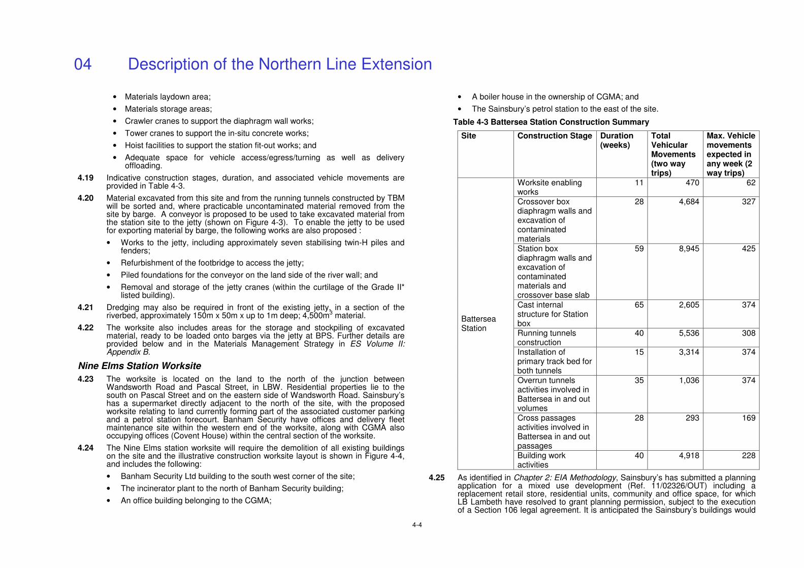
4.19 Indicative construction stages, duration, and associated vehicle movements are provided in Table 4-3.
4.20 Material excavated from this site and from the running tunnels constructed by TBM will be sorted and, where practicable uncontaminated material removed from the site by barge. A conveyor is proposed to be used to take excavated material from the station site to the jetty (shown on Figure 4-3). To enable the jetty to be used for exporting material by barge, the following works are also proposed :
• Works to the jetty, including approximately seven stabilising twin-H piles and fenders;
• Refurbishment of the footbridge to access the jetty;
• Piled foundations for the conveyor on the land side of the river wall; and
• Removal and storage of the jetty cranes (within the curtilage of the Grade II* listed building).
4.21 Dredging may also be required in front of the existing jetty, in a section of the riverbed, approximately 150m x 50m x up to 1m deep; 4,500m3 material.
4.22 The worksite also includes areas for the storage and stockpiling of excavated material, ready to be loaded onto barges via the jetty at BPS. Further details are provided below and in the Materials Management Strategy in ES Volume II: Appendix B.
Nine Elms Station Worksite
4.23 The worksite is located on the land to the north of the junction between Wandsworth Road and Pascal Street, in LBW. Residential properties lie to the south on Pascal Street and on the eastern side of Wandsworth Road. Sainsbury’s has a supermarket directly adjacent to the north of the site, with the proposed worksite relating to land currently forming part of the associated customer parking and a petrol station forecourt. Banham Security have offices and delivery fleet maintenance site within the western end of the worksite, along with CGMA also occupying offices (Covent House) within the central section of the worksite.
4.24 The Nine Elms station worksite will require the demolition of all existing buildings on the site and the illustrative construction worksite layout is shown in Figure 4-4, and includes the following:
• Banham Security Ltd building to the south west corner of the site;
• The incinerator plant to the north of Banham Security building;
• An office building belonging to the CGMA;
• A boiler house in the ownership of CGMA; and
• The Sainsbury’s petrol station to the east of the site.
Table 4-3 Battersea Station Construction Summary
Site Construction Stage Duration (weeks)
Total Vehicular Movements (two way trips)
Max. Vehicle movements expected in any week (2 way trips)
Worksite enabling works
11 470 62
Crossover box diaphragm walls and excavation of contaminated materials
28 4,684 327
Station box diaphragm walls and excavation of contaminated materials and crossover base slab
59 8,945 425
Cast internal structure for Station box
65 2,605 374
Running tunnels construction
40 5,536 308
Installation of primary track bed for both tunnels
15 3,314 374
Overrun tunnels activities involved in Battersea in and out volumes
35 1,036 374
Cross passages activities involved in Battersea in and out passages
28 293 169
Battersea Station
Building work activities
40 4,918 228
4.25 As identified in Chapter 2: EIA Methodology, Sainsbury’s has submitted a planning application for a mixed use development (Ref. 11/02326/OUT) including a replacement retail store, residential units, community and office space, for which LB Lambeth have resolved to grant planning permission, subject to the execution of a Section 106 legal agreement. It is anticipated the Sainsbury’s buildings would
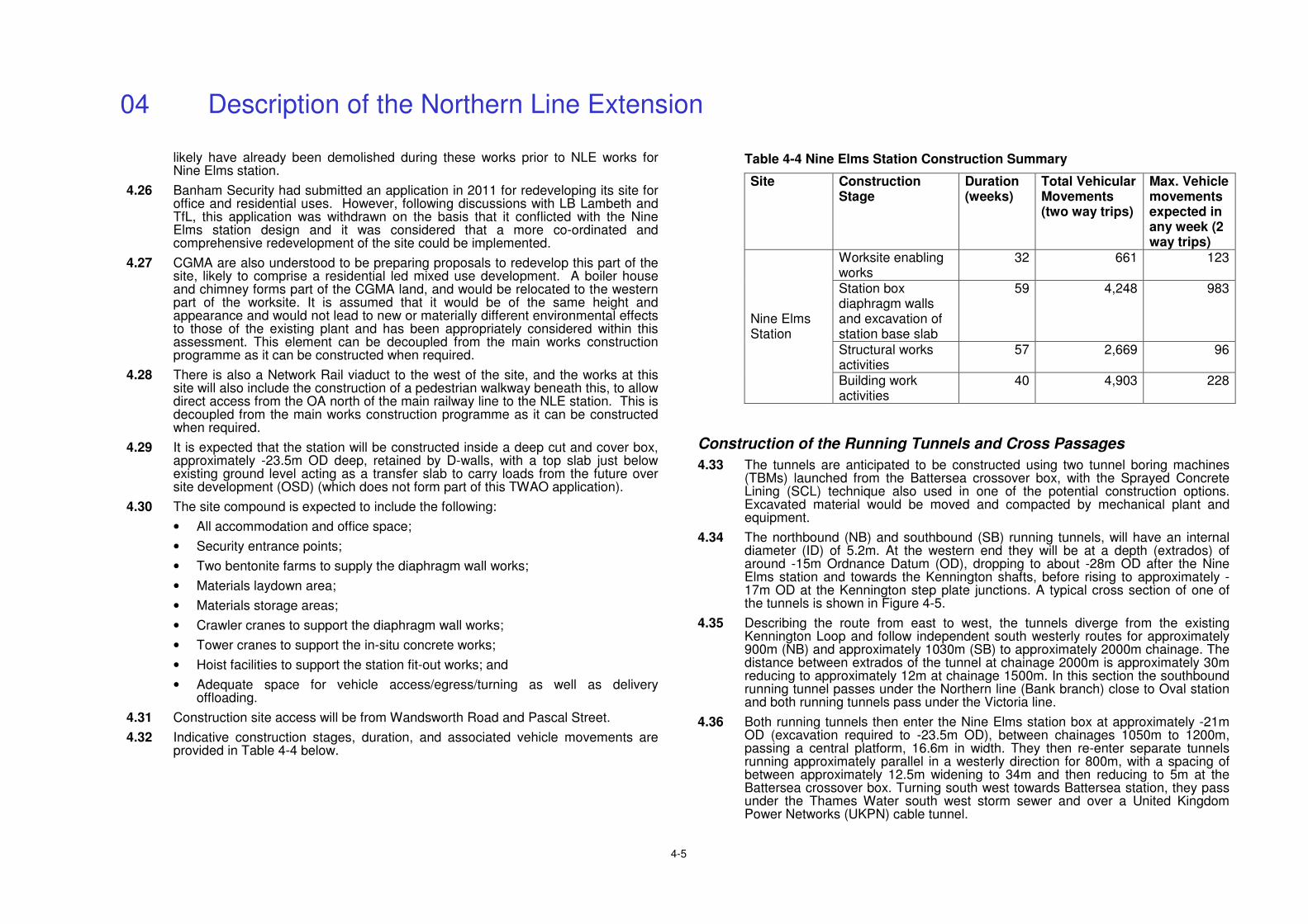
04 Description of the Northern Line Extension
4-5
likely have already been demolished during these works prior to NLE works for Nine Elms station.
4.26 Banham Security had submitted an application in 2011 for redeveloping its site for office and residential uses. However, following discussions with LB Lambeth and TfL, this application was withdrawn on the basis that it conflicted with the Nine Elms station design and it was considered that a more co-ordinated and comprehensive redevelopment of the site could be implemented.
4.27 CGMA are also understood to be preparing proposals to redevelop this part of the site, likely to comprise a residential led mixed use development. A boiler house and chimney forms part of the CGMA land, and would be relocated to the western part of the worksite. It is assumed that it would be of the same height and appearance and would not lead to new or materially different environmental effects to those of the existing plant and has been appropriately considered within this assessment. This element can be decoupled from the main works construction programme as it can be constructed when required.
4.28 There is also a Network Rail viaduct to the west of the site, and the works at this site will also include the construction of a pedestrian walkway beneath this, to allow direct access from the OA north of the main railway line to the NLE station. This is decoupled from the main works construction programme as it can be constructed when required.
4.29 It is expected that the station will be constructed inside a deep cut and cover box, approximately -23.5m OD deep, retained by D-walls, with a top slab just below existing ground level acting as a transfer slab to carry loads from the future over site development (OSD) (which does not form part of this TWAO application).
4.30 The site compound is expected to include the following:
• All accommodation and office space;
• Security entrance points;
• Two bentonite farms to supply the diaphragm wall works;
• Materials laydown area;
• Materials storage areas;
• Crawler cranes to support the diaphragm wall works;
• Tower cranes to support the in-situ concrete works;
• Hoist facilities to support the station fit-out works; and
• Adequate space for vehicle access/egress/turning as well as delivery offloading.
4.31 Construction site access will be from Wandsworth Road and Pascal Street.
4.32 Indicative construction stages, duration, and associated vehicle movements are provided in Table 4-4 below.
Table 4-4 Nine Elms Station Construction Summary
Site Construction Stage
Duration (weeks)
Total Vehicular Movements (two way trips)
Max. Vehicle movements expected in any week (2 way trips)
Worksite enabling works
32 661 123
Station box diaphragm walls and excavation of station base slab
59
4,248
983
Structural works activities
57 2,669 96
Nine Elms Station
Building work activities
40 4,903 228
Construction of the Running Tunnels and Cross Passages
4.33 The tunnels are anticipated to be constructed using two tunnel boring machines (TBMs) launched from the Battersea crossover box, with the Sprayed Concrete Lining (SCL) technique also used in one of the potential construction options. Excavated material would be moved and compacted by mechanical plant and equipment.
4.34 The northbound (NB) and southbound (SB) running tunnels, will have an internal diameter (ID) of 5.2m. At the western end they will be at a depth (extrados) of around -15m Ordnance Datum (OD), dropping to about -28m OD after the Nine Elms station and towards the Kennington shafts, before rising to approximately -17m OD at the Kennington step plate junctions. A typical cross section of one of the tunnels is shown in Figure 4-5.
4.35 Describing the route from east to west, the tunnels diverge from the existing Kennington Loop and follow independent south westerly routes for approximately 900m (NB) and approximately 1030m (SB) to approximately 2000m chainage. The distance between extrados of the tunnel at chainage 2000m is approximately 30m reducing to approximately 12m at chainage 1500m. In this section the southbound running tunnel passes under the Northern line (Bank branch) close to Oval station and both running tunnels pass under the Victoria line.
4.36 Both running tunnels then enter the Nine Elms station box at approximately -21m OD (excavation required to -23.5m OD), between chainages 1050m to 1200m, passing a central platform, 16.6m in width. They then re-enter separate tunnels running approximately parallel in a westerly direction for 800m, with a spacing of between approximately 12.5m widening to 34m and then reducing to 5m at the Battersea crossover box. Turning south west towards Battersea station, they pass under the Thames Water south west storm sewer and over a United Kingdom Power Networks (UKPN) cable tunnel.
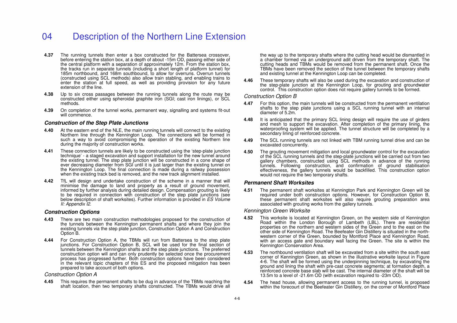
04 Description of the Northern Line Extension
4-6
4.37 The running tunnels then enter a box constructed for the Battersea crossover, before entering the station box, at a depth of about -15m OD, passing either side of the central platform with a separation of approximately 12m. From the station box, the tracks run in separate tunnels (including a short length of platform tunnel) for 185m northbound, and 168m southbound, to allow for overruns. Overrun tunnels (constructed using SCL methods) also allow train stabling, and enabling trains to enter the station at full speed, as well as providing provision for any future extension of the line.
4.38 Up to six cross passages between the running tunnels along the route may be constructed either using spheroidal graphite iron (SGI; cast iron linings), or SCL methods.
4.39 On completion of the tunnel works, permanent way, signalling and systems fit-out will commence.
Construction of the Step Plate Junctions
4.40 At the eastern end of the NLE, the main running tunnels will connect to the existing Northern line through the Kennington Loop. The connections will be formed in such a way to avoid compromising the operation of the existing Northern line during the majority of construction works.
4.41 These connection tunnels are likely to be constructed using the ‘step-plate junction technique’ - a staged excavation and support installation for the new tunnel around the existing tunnel. The step plate junction will be constructed in a cone shape of ever decreasing diameter from SGI until it is just larger than the existing tunnel on the Kennington Loop. The final connection is made during a railway possession when the existing track bed is removed, and the new track alignment installed.
4.42 TfL will design and undertake construction of the scheme in a manner that will minimise the damage to land and property as a result of ground movement, informed by further analysis during detailed design. Compensation grouting is likely to be required in connection with construction of the step plate junctions (see below description of shaft worksites). Further information is provided in ES Volume II: Appendix I2.
Construction Options
4.43 There are two main construction methodologies proposed for the construction of the tunnels between the Kennington permanent shafts and where they join the existing tunnels via the step plate junction, Construction Option A and Construction Option B.
4.44 For Construction Option A, the TBMs will run from Battersea to the step plate junctions. For Construction Option B, SCL will be used for the final section of tunnels between the Kennington shafts and the step plate junctions. The preferred construction option will and can only prudently be selected once the procurement process has progressed further. Both construction options have been considered in the relevant topic chapters of this ES and the proposed mitigation has been prepared to take account of both options.
Construction Option A
4.45 This requires the permanent shafts to be dug in advance of the TBMs reaching the shaft location, then two temporary shafts constructed. The TBMs would drive all
the way up to the temporary shafts where the cutting head would be dismantled in a chamber formed via an underground adit driven from the temporary shaft. The cutting heads and TBMs would be removed from the permanent shaft. Once the TBMs have been removed the section of the tunnel between the temporary shafts and existing tunnel at the Kennington Loop can be completed.
4.46 These temporary shafts will also be used during the excavation and construction of the step-plate junction at the Kennington Loop, for grouting and groundwater control. This construction option does not require gallery tunnels to be formed.
Construction Option B
4.47 For this option, the main tunnels will be constructed from the permanent ventilation shafts to the step plate junctions using a SCL running tunnel with an internal diameter of 5.2m.
4.48 It is anticipated that the primary SCL lining design will require the use of girders and mesh to support the excavation. After completion of the primary lining, the waterproofing system will be applied. The tunnel structure will be completed by a secondary lining of reinforced concrete.
4.49 The SCL running tunnels are not linked with TBM running tunnel drive and can be excavated concurrently.
4.50 The grouting movement mitigation and local groundwater control for the excavation of the SCL running tunnels and the step-plate junctions will be carried out from two gallery chambers, constructed using SCL methods in advance of the running tunnels. Following construction, and confirmation of ground stabilisation effectiveness, the gallery tunnels would be backfilled. This construction option would not require the two temporary shafts.
Permanent Shaft Worksites
4.51 The permanent shaft worksites at Kennington Park and Kennington Green will be required under both construction options. However, for Construction Option B, these permanent shaft worksites will also require grouting preparation area associated with grouting works from the gallery tunnels.
Kennington Green Worksite
4.52 This worksite is located at Kennington Green, on the western side of Kennington Road within the London Borough of Lambeth (LBL). There are residential properties on the northern and western sides of the Green and to the east on the other side of Kennington Road. The Beefeater Gin Distillery is situated in the north-western corner of the Green, bounded by Montford Place and Kennington Road, with an access gate and boundary wall facing the Green. The site is within the Kennington Conservation Area.
4.53 The northbound ventilation shaft will be excavated from a site within the south east corner of Kennington Green, as shown in the illustrative worksite layout in Figure 4-6. The shaft will be formed using the underpinning technique, by excavating the ground and lining the shaft with pre-cast concrete segments; at formation depth, a reinforced concrete base slab will be cast. The internal diameter of the shaft will be 13.5m to a level of -21.6m OD (with excavation required to -23m OD).
4.54 The head house, allowing permanent access to the running tunnel, is proposed within the forecourt of the Beefeater Gin Distillery, on the corner of Montford Place
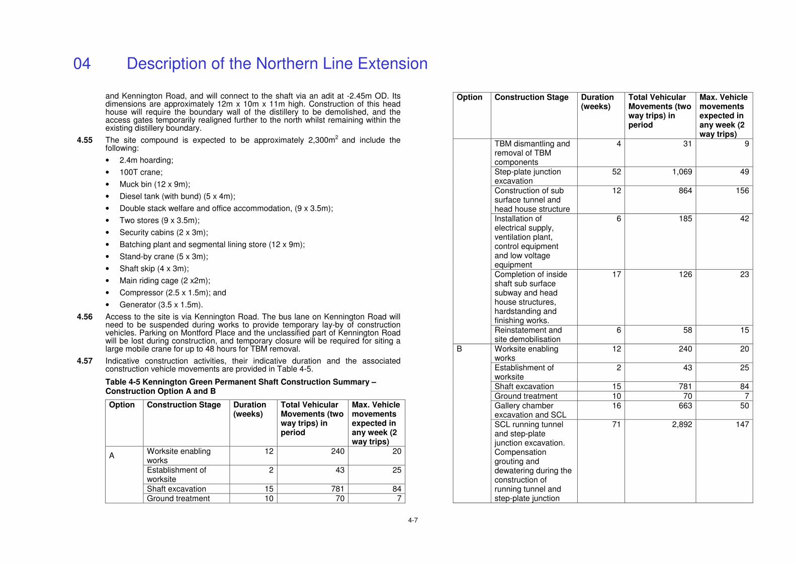
04 Description of the Northern Line Extension
4-7
and Kennington Road, and will connect to the shaft via an adit at -2.45m OD. Its dimensions are approximately 12m x 10m x 11m high. Construction of this head house will require the boundary wall of the distillery to be demolished, and the access gates temporarily realigned further to the north whilst remaining within the existing distillery boundary.
4.55 The site compound is expected to be approximately 2,300m2 and include the following:
• 2.4m hoarding;
• 100T crane;
• Muck bin (12 x 9m);
• Diesel tank (with bund) (5 x 4m);
• Double stack welfare and office accommodation, (9 x 3.5m);
• Two stores (9 x 3.5m);
• Security cabins (2 x 3m);
• Batching plant and segmental lining store (12 x 9m);
• Stand-by crane (5 x 3m);
• Shaft skip (4 x 3m);
• Main riding cage (2 x2m);
• Compressor (2.5 x 1.5m); and
• Generator (3.5 x 1.5m).
4.56 Access to the site is via Kennington Road. The bus lane on Kennington Road will need to be suspended during works to provide temporary lay-by of construction vehicles. Parking on Montford Place and the unclassified part of Kennington Road will be lost during construction, and temporary closure will be required for siting a large mobile crane for up to 48 hours for TBM removal.
4.57 Indicative construction activities, their indicative duration and the associated construction vehicle movements are provided in Table 4-5.
Table 4-5 Kennington Green Permanent Shaft Construction Summary – Construction Option A and B
Option Construction Stage Duration (weeks)
Total Vehicular Movements (two way trips) in period
Max. Vehicle movements expected in any week (2 way trips)
Worksite enabling works
12 240 20
Establishment of worksite
2 43 25
Shaft excavation 15 781 84
A
Ground treatment 10 70 7
Option Construction Stage Duration (weeks)
Total Vehicular Movements (two way trips) in period
Max. Vehicle movements expected in any week (2 way trips)
TBM dismantling and removal of TBM components
4 31 9
Step-plate junction excavation
52 1,069 49
Construction of sub surface tunnel and head house structure
12 864 156
Installation of electrical supply, ventilation plant, control equipment and low voltage equipment
6 185 42
Completion of inside shaft sub surface subway and head house structures, hardstanding and finishing works.
17 126 23
Reinstatement and site demobilisation
6 58 15
Worksite enabling works
12 240 20
Establishment of worksite
2 43 25
Shaft excavation 15 781 84
Ground treatment 10 70 7 Gallery chamber excavation and SCL
16 663 50
B
SCL running tunnel and step-plate junction excavation. Compensation grouting and dewatering during the construction of running tunnel and step-plate junction
71 2,892 147
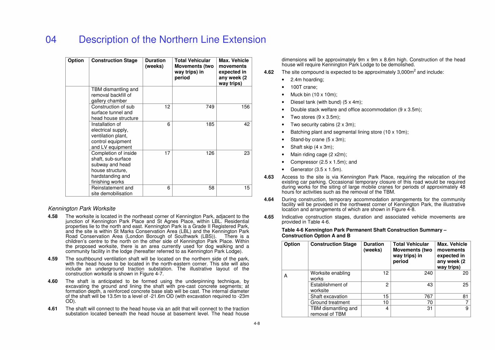
04 Description of the Northern Line Extension
4-8
Option Construction Stage Duration (weeks)
Total Vehicular Movements (two way trips) in period
Max. Vehicle movements expected in any week (2 way trips)
TBM dismantling and removal backfill of gallery chamber Construction of sub surface tunnel and head house structure
12 749 156
Installation of electrical supply, ventilation plant, control equipment and LV equipment
6 185 42
Completion of inside shaft, sub-surface subway and head house structure, hardstanding and finishing works
17 126 23
Reinstatement and site demobilisation
6 58
15
Kennington Park Worksite
4.58 The worksite is located in the northeast corner of Kennington Park, adjacent to the junction of Kennington Park Place and St Agnes Place, within LBL. Residential properties lie to the north and east. Kennington Park is a Grade II Registered Park, and the site is within St Marks Conservation Area (LBL) and the Kennington Park Road Conservation Area (London Borough of Southwark (LBS)). There is a children’s centre to the north on the other side of Kennington Park Place. Within the proposed worksite, there is an area currently used for dog walking and a community facility in the lodge (hereafter referred to as Kennington Park Lodge).
4.59 The southbound ventilation shaft will be located on the northern side of the park, with the head house to be located in the north-eastern corner. This site will also include an underground traction substation. The illustrative layout of the construction worksite is shown in Figure 4-7.
4.60 The shaft is anticipated to be formed using the underpinning technique, by excavating the ground and lining the shaft with pre-cast concrete segments; at formation depth, a reinforced concrete base slab will be cast. The internal diameter of the shaft will be 13.5m to a level of -21.6m OD (with excavation required to -23m OD).
4.61 The shaft will connect to the head house via an adit that will connect to the traction substation located beneath the head house at basement level. The head house
dimensions will be approximately 9m x 9m x 8.6m high. Construction of the head house will require Kennington Park Lodge to be demolished.
4.62 The site compound is expected to be approximately 3,000m2 and include:
• 2.4m hoarding;
• 100T crane;
• Muck bin (10 x 10m);
• Diesel tank (with bund) (5 x 4m);
• Double stack welfare and office accommodation (9 x 3.5m);
• Two stores (9 x 3.5m);
• Two security cabins (2 x 3m);
• Batching plant and segmental lining store (10 x 10m);
• Stand-by crane (5 x 3m);
• Shaft skip (4 x 3m);
• Main riding cage (2 x2m);
• Compressor (2.5 x 1.5m); and
• Generator (3.5 x 1.5m).
4.63 Access to the site is via Kennington Park Place, requiring the relocation of the existing car parking. Occasional temporary closure of this road would be required during works for the siting of large mobile cranes for periods of approximately 48 hours for activities such as the removal of the TBM.
4.64 During construction, temporary accommodation arrangements for the community facility will be provided in the northwest corner of Kennington Park, the illustrative location and arrangements of which are shown in Figure 4-8.
4.65 Indicative construction stages, duration and associated vehicle movements are provided in Table 4-6.
Table 4-6 Kennington Park Permanent Shaft Construction Summary – Construction Option A and B
Option Construction Stage Duration (weeks)
Total Vehicular Movements (two way trips) in period
Max. Vehicle movements expected in any week (2 way trips)
Worksite enabling works
12 240 20
Establishment of worksite
2 43 25
Shaft excavation 15 767 81 Ground treatment 10 70 7
A
TBM dismantling and removal of TBM
4 31 9
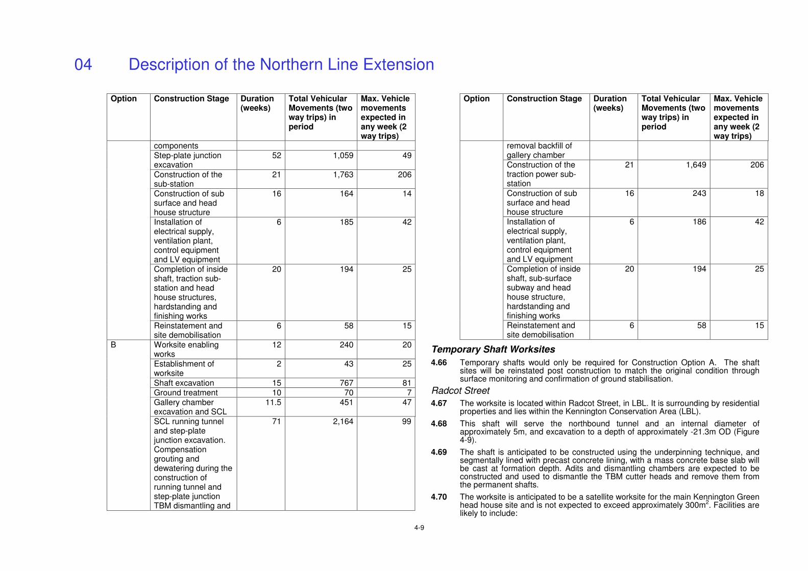
04 Description of the Northern Line Extension
4-9
Option Construction Stage Duration (weeks)
Total Vehicular Movements (two way trips) in period
Max. Vehicle movements expected in any week (2 way trips)
components Step-plate junction excavation
52 1,059 49
Construction of the sub-station
21 1,763 206
Construction of sub surface and head house structure
16 164 14
Installation of electrical supply, ventilation plant, control equipment and LV equipment
6 185 42
Completion of inside shaft, traction sub-station and head house structures, hardstanding and finishing works
20 194 25
Reinstatement and site demobilisation
6 58 15
Worksite enabling works
12 240 20
Establishment of worksite
2 43 25
Shaft excavation 15 767 81 Ground treatment 10 70 7 Gallery chamber excavation and SCL
11.5 451 47
B
SCL running tunnel and step-plate junction excavation. Compensation grouting and dewatering during the construction of running tunnel and step-plate junction TBM dismantling and
71 2,164 99
Option Construction Stage Duration (weeks)
Total Vehicular Movements (two way trips) in period
Max. Vehicle movements expected in any week (2 way trips)
removal backfill of gallery chamber Construction of the traction power sub-station
21 1,649 206
Construction of sub surface and head house structure
16 243 18
Installation of electrical supply, ventilation plant, control equipment and LV equipment
6 186 42
Completion of inside shaft, sub-surface subway and head house structure, hardstanding and finishing works
20 194 25
Reinstatement and site demobilisation
6 58 15
Temporary Shaft Worksites
4.66 Temporary shafts would only be required for Construction Option A. The shaft sites will be reinstated post construction to match the original condition through surface monitoring and confirmation of ground stabilisation.
Radcot Street
4.67 The worksite is located within Radcot Street, in LBL. It is surrounding by residential properties and lies within the Kennington Conservation Area (LBL).
4.68 This shaft will serve the northbound tunnel and an internal diameter of approximately 5m, and excavation to a depth of approximately -21.3m OD (Figure 4-9).
4.69 The shaft is anticipated to be constructed using the underpinning technique, and segmentally lined with precast concrete lining, with a mass concrete base slab will be cast at formation depth. Adits and dismantling chambers are expected to be constructed and used to dismantle the TBM cutter heads and remove them from the permanent shafts.
4.70 The worksite is anticipated to be a satellite worksite for the main Kennington Green head house site and is not expected to exceed approximately 300m2. Facilities are likely to include:
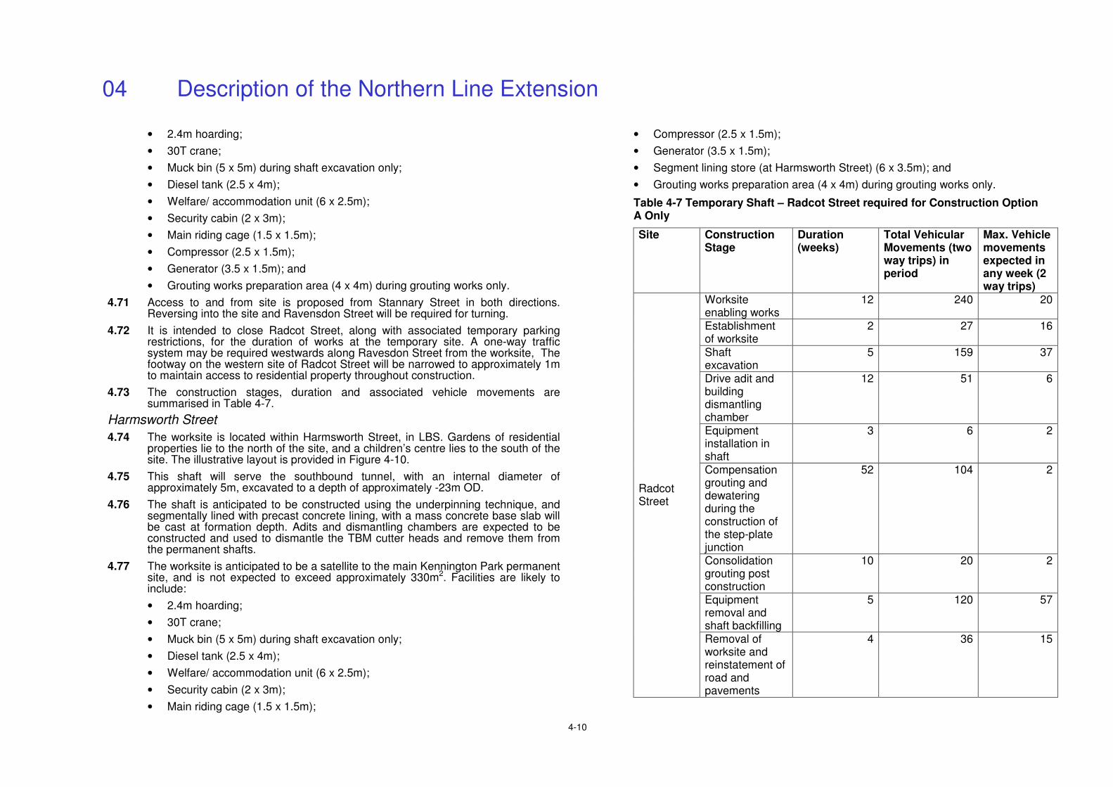
04 Description of the Northern Line Extension
4-10
• 2.4m hoarding;
• 30T crane;
• Muck bin (5 x 5m) during shaft excavation only;
• Diesel tank (2.5 x 4m);
• Welfare/ accommodation unit (6 x 2.5m);
• Security cabin (2 x 3m);
• Main riding cage (1.5 x 1.5m);
• Compressor (2.5 x 1.5m);
• Generator (3.5 x 1.5m); and
• Grouting works preparation area (4 x 4m) during grouting works only.
4.71 Access to and from site is proposed from Stannary Street in both directions. Reversing into the site and Ravensdon Street will be required for turning.
4.72 It is intended to close Radcot Street, along with associated temporary parking restrictions, for the duration of works at the temporary site. A one-way traffic system may be required westwards along Ravesdon Street from the worksite, The footway on the western site of Radcot Street will be narrowed to approximately 1m to maintain access to residential property throughout construction.
4.73 The construction stages, duration and associated vehicle movements are summarised in Table 4-7.
Harmsworth Street
4.74 The worksite is located within Harmsworth Street, in LBS. Gardens of residential properties lie to the north of the site, and a children’s centre lies to the south of the site. The illustrative layout is provided in Figure 4-10.
4.75 This shaft will serve the southbound tunnel, with an internal diameter of approximately 5m, excavated to a depth of approximately -23m OD.
4.76 The shaft is anticipated to be constructed using the underpinning technique, and segmentally lined with precast concrete lining, with a mass concrete base slab will be cast at formation depth. Adits and dismantling chambers are expected to be constructed and used to dismantle the TBM cutter heads and remove them from the permanent shafts.
4.77 The worksite is anticipated to be a satellite to the main Kennington Park permanent site, and is not expected to exceed approximately 330m2. Facilities are likely to include:
• 2.4m hoarding;
• 30T crane;
• Muck bin (5 x 5m) during shaft excavation only;
• Diesel tank (2.5 x 4m);
• Welfare/ accommodation unit (6 x 2.5m);
• Security cabin (2 x 3m);
• Main riding cage (1.5 x 1.5m);
• Compressor (2.5 x 1.5m);
• Generator (3.5 x 1.5m);
• Segment lining store (at Harmsworth Street) (6 x 3.5m); and
• Grouting works preparation area (4 x 4m) during grouting works only.
Table 4-7 Temporary Shaft – Radcot Street required for Construction Option A Only
Site Construction Stage
Duration (weeks)
Total Vehicular Movements (two way trips) in period
Max. Vehicle movements expected in any week (2 way trips)
Worksite enabling works
12 240 20
Establishment of worksite
2 27 16
Shaft excavation
5 159 37
Drive adit and building dismantling chamber
12 51 6
Equipment installation in shaft
3 6 2
Compensation grouting and dewatering during the construction of the step-plate junction
52 104 2
Consolidation grouting post construction
10 20 2
Equipment removal and shaft backfilling
5 120 57
Radcot Street
Removal of worksite and reinstatement of road and pavements
4 36 15
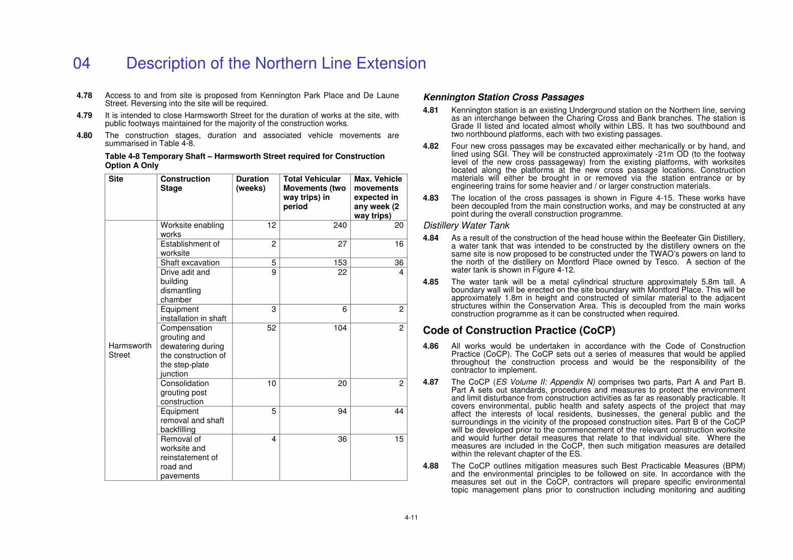
04 Description of the Northern Line Extension
4-11
4.78 Access to and from site is proposed from Kennington Park Place and De Laune Street. Reversing into the site will be required.
4.79 It is intended to close Harmsworth Street for the duration of works at the site, with public footways maintained for the majority of the construction works.
4.80 The construction stages, duration and associated vehicle movements are summarised in Table 4-8.
Table 4-8 Temporary Shaft – Harmsworth Street required for Construction Option A Only
Site Construction Stage
Duration (weeks)
Total Vehicular Movements (two way trips) in period
Max. Vehicle movements expected in any week (2 way trips)
Worksite enabling works
12 240 20
Establishment of worksite
2 27 16
Shaft excavation 5 153 36 Drive adit and building dismantling chamber
9 22 4
Equipment installation in shaft
3 6 2
Compensation grouting and dewatering during the construction of the step-plate junction
52 104 2
Consolidation grouting post construction
10 20 2
Equipment removal and shaft backfilling
5 94 44
Harmsworth Street
Removal of worksite and reinstatement of road and pavements
4 36 15
Kennington Station Cross Passages
4.81 Kennington station is an existing Underground station on the Northern line, serving as an interchange between the Charing Cross and Bank branches. The station is Grade II listed and located almost wholly within LBS. It has two southbound and two northbound platforms, each with two existing passages.
4.82 Four new cross passages may be excavated either mechanically or by hand, and lined using SGI. They will be constructed approximately -21m OD (to the footway level of the new cross passageway) from the existing platforms, with worksites located along the platforms at the new cross passage locations. Construction materials will either be brought in or removed via the station entrance or by engineering trains for some heavier and / or larger construction materials.
4.83 The location of the cross passages is shown in Figure 4-15. These works have been decoupled from the main construction works, and may be constructed at any point during the overall construction programme.
Distillery Water Tank
4.84 As a result of the construction of the head house within the Beefeater Gin Distillery, a water tank that was intended to be constructed by the distillery owners on the same site is now proposed to be constructed under the TWAO’s powers on land to the north of the distillery on Montford Place owned by Tesco. A section of the water tank is shown in Figure 4-12.
4.85 The water tank will be a metal cylindrical structure approximately 5.8m tall. A boundary wall will be erected on the site boundary with Montford Place. This will be approximately 1.8m in height and constructed of similar material to the adjacent structures within the Conservation Area. This is decoupled from the main works construction programme as it can be constructed when required.
Code of Construction Practice (CoCP)
4.86 All works would be undertaken in accordance with the Code of Construction Practice (CoCP). The CoCP sets out a series of measures that would be applied throughout the construction process and would be the responsibility of the contractor to implement.
4.87 The CoCP (ES Volume II: Appendix N) comprises two parts, Part A and Part B. Part A sets out standards, procedures and measures to protect the environment and limit disturbance from construction activities as far as reasonably practicable. It covers environmental, public health and safety aspects of the project that may affect the interests of local residents, businesses, the general public and the surroundings in the vicinity of the proposed construction sites. Part B of the CoCP will be developed prior to the commencement of the relevant construction worksite and would further detail measures that relate to that individual site. Where the measures are included in the CoCP, then such mitigation measures are detailed within the relevant chapter of the ES.
4.88 The CoCP outlines mitigation measures such Best Practicable Measures (BPM) and the environmental principles to be followed on site. In accordance with the measures set out in the CoCP, contractors will prepare specific environmental topic management plans prior to construction including monitoring and auditing
04 Description of the Northern Line Extension
4-12
regimes. Further procedures to be developed in line with contractor procurement and mobilisation include:
• Health, Safety, Quality and Environment Systems, including as a minimum an Environmental Management System (EMS);
• Contractor’s Environmental Management Plan;
• Site environmental management plan(s);
• Traffic management plan(s);
• Site waste management plans;
• Air quality and dust management plan;
• Water conservation plan;
• Green travel plan;
• Energy management plan;
• Ecology management plan; and
• Ecology reinstatement plan.
General Site Operations
4.89 Normal working hours are planned to be from 0800 to 1800 on weekdays (Mon-Fri excluding Bank Holidays) and 0800 to 1300 on Saturdays. Where feasible, operations likely to cause disturbance and/or disruption would be limited to within these hours. Start up and shut down activities such as maintenance, site briefings, meetings and training will take place for up to one hour before and after these times. Tunnelling activities which necessitate continuous working hours would be required over a period of up to 22 months. During these periods only those activities directly connected with the task would be permitted. However, it is noted that there would be periods of activity within this phase where continuous 24 hour working would not be required. These assumptions have been assessed in the ES.
4.90 The sites will be appropriately screened and secured, with site hoardings, lighting at the minimum luminosity necessary and signage.
4.91 Appropriate control systems will be in place at sites for the arrival and dispatch of construction vehicles, including holding areas, road cleanliness, and signage.
Groundwater Control
4.92 This will likely be required at the temporary shaft sites and station boxes during excavation until segmented linings and D-walls (respectively) have been constructed. Suitable discharge consents and licences will be sought prior to these activities commencing.
Materials Strategy Summary
4.93 As stated above, material from the excavation of Battersea station is anticipated to be stockpiled at the Battersea station worksite, along with excavated material from the running tunnels, having been transported from the cutting face by a temporary construction railway. A stockpile with capacity in the region of 10,000m3 is anticipated, although this is sized as a contingency to account for the necessary
contingency to take account of periods when barges may not be able to transport excavated material, such as times of poor weather conditions, river obstruction or closure of the Thames Barrier. Any contaminated material would be handled and sorted prior to it being stockpiled and in accordance with the measures set out in the CoCP.
4.94 Wherever practicable, any excavated material that is not contaminated will be loaded via an inclined conveyor into a hopper. Material will then be transported via a series of conveyors to the jetty to the north of the worksite, where it will be loaded into the barges. Under Option A and Option B an estimated 70% and 68% (by volume) respectively of material is expected to be removed by barge, with the remainder by road.
4.95 Two barges, likely dumb (non-motorised) 1,000 tonne barges, will be docked at the jetty for removal of excavated material during each high tide, allowing the barges to travel up river with the rising tide and down river with the ebb tide. Once loaded, the barges will travel to a transhipment facility, assumed to be at Northfleet, where the cargo will be loaded into motorised sea-going vessels, for transport to the receiving site, assumed at this point to be Wallasea Island in the Thames Estuary. This will be confirmed during the detailed design stage, in collaboration with other consented cumulative projects.
4.96 Excavated material from the other worksites will be sorted on-site, with the uncontaminated material being transported by road directly to the transhipment facility.
4.97 Any contaminated material discovered will be assessed in terms of its remediation potential, and treated/disposed of accordingly. The dredged material from the riverbed surrounding the jetty is likely to be contaminated and will be segregated and disposed of at a suitable site.
4.98 In accordance with the waste hierarchy, opportunities for the reduction and reuse of waste have been implemented. Waste from construction materials and other associated works will be segregated and removed to suitable disposal sites as appropriate. The most significant waste stream other than excavated spoil will be generated from SCL. This is considered to be non-hazardous, and will be segregated and disposed of accordingly. Tables 4-9 and 4-10 provided estimated materials streams and quantities.
4.99 Further details are provided in the Materials Management Strategy in ES Volume II: Appendix B.
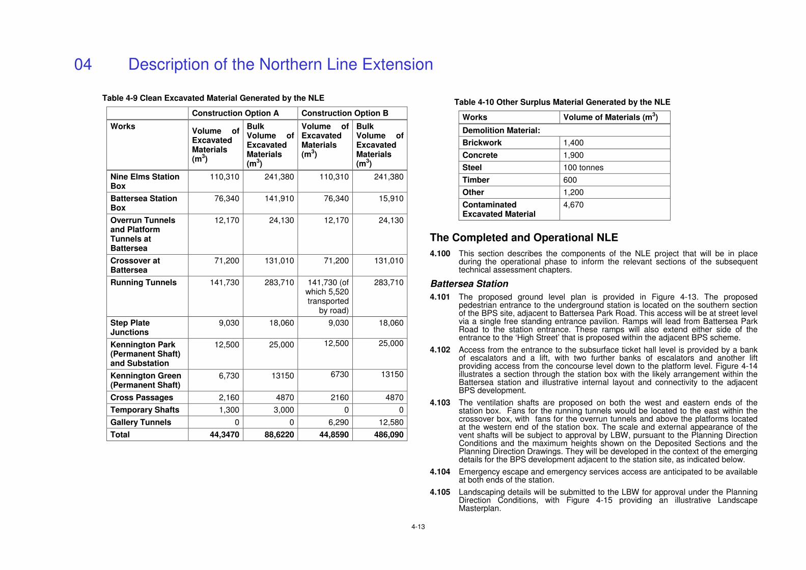
04 Description of the Northern Line Extension
4-13
Table 4-9 Clean Excavated Material Generated by the NLE
Construction Option A Construction Option B
Works Volume of Excavated Materials (m3)
Bulk Volume of Excavated Materials (m3)
Volume of Excavated Materials (m3)
Bulk Volume of Excavated Materials (m3)
Nine Elms Station Box
110,310 241,380 110,310 241,380
Battersea Station Box
76,340 141,910 76,340 15,910
Overrun Tunnels and Platform Tunnels at Battersea
12,170 24,130 12,170 24,130
Crossover at Battersea
71,200 131,010 71,200 131,010
Running Tunnels 141,730 283,710 141,730 (of which 5,520 transported
by road)
283,710
Step Plate Junctions
9,030 18,060 9,030 18,060
Kennington Park (Permanent Shaft) and Substation
12,500 25,000 12,500 25,000
Kennington Green (Permanent Shaft)
6,730 13150 6730 13150
Cross Passages 2,160 4870 2160 4870
Temporary Shafts 1,300 3,000 0 0
Gallery Tunnels 0 0 6,290 12,580
Total 44,3470 88,6220 44,8590 486,090
Table 4-10 Other Surplus Material Generated by the NLE
Works Volume of Materials (m3)
Demolition Material:
Brickwork 1,400
Concrete 1,900
Steel 100 tonnes
Timber 600
Other 1,200
Contaminated Excavated Material
4,670
The Completed and Operational NLE
4.100 This section describes the components of the NLE project that will be in place during the operational phase to inform the relevant sections of the subsequent technical assessment chapters.
Battersea Station
4.101 The proposed ground level plan is provided in Figure 4-13. The proposed pedestrian entrance to the underground station is located on the southern section of the BPS site, adjacent to Battersea Park Road. This access will be at street level via a single free standing entrance pavilion. Ramps will lead from Battersea Park Road to the station entrance. These ramps will also extend either side of the entrance to the ‘High Street’ that is proposed within the adjacent BPS scheme.
4.102 Access from the entrance to the subsurface ticket hall level is provided by a bank of escalators and a lift, with two further banks of escalators and another lift providing access from the concourse level down to the platform level. Figure 4-14 illustrates a section through the station box with the likely arrangement within the Battersea station and illustrative internal layout and connectivity to the adjacent BPS development.
4.103 The ventilation shafts are proposed on both the west and eastern ends of the station box. Fans for the running tunnels would be located to the east within the crossover box, with fans for the overrun tunnels and above the platforms located at the western end of the station box. The scale and external appearance of the vent shafts will be subject to approval by LBW, pursuant to the Planning Direction Conditions and the maximum heights shown on the Deposited Sections and the Planning Direction Drawings. They will be developed in the context of the emerging details for the BPS development adjacent to the station site, as indicated below.
4.104 Emergency escape and emergency services access are anticipated to be available at both ends of the station.
4.105 Landscaping details will be submitted to the LBW for approval under the Planning Direction Conditions, with Figure 4-15 providing an illustrative Landscape Masterplan.
04 Description of the Northern Line Extension
4-14
4.106 Battersea station is also described in the Design and Access Statement (see ES Volume II: Appendix M).
Adjacent Battersea Power Station Scheme
4.107 The BPS scheme was granted outline planning permission in 2011 (Planning Application Ref. 2009/3575). The BPS scheme will eventually provide approximately 3,500 homes with new shops, restaurants, cafes and bars, offices, hotel and conference facilities, community facilities and a new riverside park. In accordance with TfL’s proposed station siting, the BPS scheme assumes the station would be located at the southern end of the retail street, known as the ‘High Street’, set back from Battersea Park Road. The northern end of the High Street would be anchored by a new Town Square in front of the restored Power Station building.
4.108 The proposed layout of Battersea station takes account of a potential additional provision for two sets of escalators on either side of the main station escalators to enable access from street level to the lower level retail street to be provided by the developer. Whilst these escalators (and their associated plant) will be outside of TfL’s management and of the station box itself, they have been included in the plans to illustrate how they could be incorporated at a future date by the BPS developer.
4.109 A fire door at ticket hall level will isolate the BPS scheme’s escalators from the ticket hall in an emergency situation in either the retail element or the station itself.
Nine Elms Station
4.110 Nine Elms station is proposed to include a street level ticket hall facing Wandsworth Road, with entrances from Pascal Street and the pedestrianised street proposed as part of the Sainsbury’s scheme to the north. A bank of escalators and a lift provide access from the ticket hall to platform level.
4.111 The proposed ground level plan is shown in Figure 4-16, with a section provided in Figure 4-17.
4.112 Two ventilation shafts are proposed and anticipated to be located at both the western and eastern ends of the station box. Details of scale and external appearance of the shafts will be subject to approval by LBL, pursuant to the Planning Direction Conditions and the maximum heights shown on the Deposited sections and the Planning Direction Drawings. They will be developed in the context of any emerging proposals for the over site development above the station. Details of any interim arrangement will also be submitted and approved as necessary.
4.113 A Distribution Network Operator (DNO) substation is proposed to be located at basement level in the western core of the station, with a traction substation at basement level across the station box. Attenuators and plant rooms would be located within the station box. A fire water holding tank is located below platform level, with emergency escape and emergency services access is available at both ends of the station.
4.114 A new pedestrian walkway is proposed to the north of the station, beneath the existing railway viaduct, to provide access from Pascal Street to the emerging CGMA development and beyond. An illustrative landscape masterplan is provided
in Figure 4-18, with the public realm context (including the walkway) shown in Figure 4-19.
Kennington Station Cross Passages
4.115 New cross passageways between the two southbound and two northbound platforms are proposed, with each pair of platforms linked by two extra cross passageways to provide additional capacity for the existing cross platform interchange routes at Kennington station. They will increase station capacity necessary to accommodate the extra passengers resulting from the NLE.
Kennington Green Head House and Public Realm Improvements
4.116 The head house will provide approximately 270m2 of space for ventilation and intervention and maintenance access. In addition, the head house will provide at least 45m2 of external louvres to allow for main tunnel ventilation.
4.117 A ground level plan is provided in Figure 4-20 and a section through the shaft, adit, and head house is provided in Figure 4-21.
4.118 The materials have been selected to reflect the adjacent properties, with the proposed walls to comprise London Stock brick. The scale and massing of the structure relates to the proportions of the existing houses on the Green, with building of residential proportions, a smaller top storey and a set back roof.
4.119 The illustrative public realm landscape masterplan is shown in Figure 4-22.
Kennington Park Head House, Traction Substation, Community Facility and Public Realm Improvements
4.120 Kennington Park Lodge is proposed to be demolished, with the head house and traction substation and replacement community facility located on its current footprint. Outdoor garden space will also be re-provided for community uses.
4.121 The proposed head house provides accommodation for ventilation and intervention and maintenance access. In addition, the head house will provide at least 45m2 of external louvers to allow for main tunnel ventilation.
4.122 The ground and mezzanine levels of the head house and community facility are shown in Figure 4-23. Sections of the Kennington Park shaft, traction substation and head house are shown in Figure 4-24.
4.123 The illustrative Landscape Masterplan site is shown in Figure 4-25.
Train Operations
4.124 Trains from the Charing Cross branch will serve the NLE, with an initial operation service frequency that will provide 16 trains per hour (tph), increasing to up to 28 tph in each direction at peak times by 2031.
4.125 There will be a 5-6 minutes’ journey time between Kennington and Battersea stations.
Station Operations
4.126 The stations will each be controlled from a Station Supervisor’s Office with a largely glazed frontage to aid passive surveillance over the ticket hall. Full radio and closed circuit television coverage will be provided throughout, along with
04 Description of the Northern Line Extension
4-15
communications systems that are compatible with the existing Northern line, to ensure continuity of type and maximise reliability. The stations will be staffed with appropriate numbers necessary to ensure safe and efficient operation.
4.127 Permanent rights will be required to access the stations for operation and maintenance 24 hours per day, 365 days a year. Rights of escape to places of safety, as well as access to and from stations for travelling passengers, will also be required.
4.128 Hours of operation are anticipated to fit the usual LUL operational hours of c.05:00-01:00 Monday-Saturday and c.06:00-01:00 Sunday, though actual hours may extend beyond this or may be curtailed to suit ongoing operational plans and events as required. For the purposes of this assessment LUL’s stated intention to extend the hours of service on Friday and Saturday evenings by one hour have also been taken into account.
4.129 The stations will be designed in accordance with the LUL’s Station Planning standard in order to ensure crowding remains within acceptable levels of service. A range of passenger operated machines will be provided in order to enable the purchase of tickets.
4.130 For underground stations, security of power supply is very important. Therefore dual supplies from totally separate sources shall originate from LUL’s own independent power source (Power Service Contractor – Powerlink) and from the local DNO. The Outline Energy Strategy (see ES Volume II: Appendix O) provides further detail and assessment of the electrical load assessment schedule for the NLE.
4.131 The telecommunications facilities at both stations, including its control arrangements will allow for the safe evacuation of each station in an emergency. Equipment rooms, plant rooms, lift, and escalator machine rooms will have a means of communication with the station control room/point. Communications will be provided (audio and data) from all Line Control Centres to other Control Centres, and with emergency services and trains.
Ventilation Shaft Maintenance
4.132 Under normal operations, the NLE will be ventilated passively (i.e. without fans). However, they will be required for smoke control, or when underground temperatures become too high.
4.133 Ventilation fan motors and drive system operation will be controlled by computer. Performance, noise and vibration monitoring and fault reporting will be carried out by an automatic control system. There is expected to be no routine testing of this equipment.
4.134 Planned Preventive Maintenance (PPM) if required will be carried out in accordance with the equipment manufactures instructions. The fans are required to be tested for a limited period every week, during normal working hours. Access to the ventilation shafts for personnel, tools, test equipment and replacement items will be required during traffic and engineering hours.