
Synthesis of Cobalt Phosphides and Their Application as Anodes for Lithium Ion Batteries
7
Synthesis of Cobalt Phosphides and Their Application as Anodes for Lithium Ion Batteries Dan Yang, †,‡ Jixin Zhu, †,‡ Xianhong Rui, †,⊥ Huiteng Tan, † Ren Cai, ⊥ Harry E. Hoster, ‡ Denis Y. W. Yu, ‡,§ Huey Hoon Hng, † and Qingyu Yan* ,†,‡,§ † School of Materials Science and Engineering, Nanyang Technological University, Singapore 639798, Singapore ‡ TUM CREATE Research Centre@NTU, Nanyang Technological University, Singapore 637459, Singapore § Energy Research Institute@NTU, Nanyang Technological University, Singapore 637553, Singapore ⊥ School of Civil and Environmental Engineering, Nanyang Technological University, Singapore 639798, Singapore * S Supporting Information ABSTRACT: A facile thermal decomposing method has been developed for the fabrication of Co x P nanostructures with controlled size, phase, and shape (e.g., Co 2 P rod and spheres, CoP hollow and solid particles). An amorphous carbon layer could be introduced by the carbonization of organic surfactants from the precursors. The electrochemical performance of typical CoP and Co 2 P samples as anode materials has been investigated and the CoP hollow nanoparticle with carbon coating layer depicts good capacity retention and high rate capability (e.g., specific capacity of 630 mA h g −1 at 0.2 C after 100 cycles, and a reversible capacity of 256 mA h g −1 can be achieved at a high current rate of 5 C). KEYWORDS: hollow nanoparticles, nanorods, Li storage, cobalt phosphides, oil phase synthesis ■ INTRODUCTION Transition metal phosphides (MP x , where M = Fe, Co, Ni, etc.) are considered to be alternative anode materials for lithium ion battery (LIB) because of their high gravimetric and volumetric capacities (500−1800 mAh g −1 ). 1 However, one major drawback that limits their practical application is the drastic volume change generated during the Li + intercalation/ deintercalation process. 1−3 This volume change can cause pulverization of the initial crystal structure and loss of electrical contact between active materials and the current collector, which lead to poor capacity retention and short cycle life. Constructing materials into nanostructures with controlled morphologies (e.g., nanotubes, 4 nanorods, 5 and hollow spheres 6 ) is one attractive approach to address this problem. Such architectures can provide higher interfacial contact area as well as better accommodation for the volume expansion and are expected to lead to a better capability. 7−10 Another challenge for practical application of MP x is their intrinsically low electronic conductivity. Generally, hybridizing the electrode materials with carbonaceous materials, e.g. carbon shell/ network, can effectively enhance the kinetics of charge transfer and improve their lithium storage performance. 11,12 Moreover, the carbon layer can either buffer the strain caused by structural or volume changes, or prevent the agglomeration of active materials during cycling process. 13,14 Cobalt phosphides (e.g., orthorhombic Co 2 P and CoP phases) are expected to be promising anode materials for their relatively low charge−discharge potential, 15 metallic character and good thermal stability. 16 With the advances in recent nanotechnology, 17−19 various synthetic methods have been developed for the synthesis of Co 2 P and CoP nanoma- terials. 20−32 However, attractive lithium storage properties (e.g., stable cyclability and high rate capability) have not been achieved for Co 2 P/CoP anodes owing to the aforementioned issues yet. Herein, we report a solution-phase synthesis of different structured Co 2 P and CoP (e.g., particles, rods, hollow spheres, and solid spheres) by decomposing Co-TOP complex in a hot oleylamine (OAm) solution. The effects of synthesis parameters (e.g., injection rate of the precursors and reaction time) on the morphology and phase of the product are investigated in detail. Comparison of the Li storage properties for different nanostructures and phases has been systematically carried out. As shown in the results, control over the shape or microstructure of cobalt phosphides can lead to enhanced Li storage properties. Specifically, the CoP hollow nanoparticles delivered a discharge capacity of 630 mA h g −1 during the 100th cycle at a charge/discharge rate of 0.2 C. Even at a high rate of Received: November 28, 2012 Accepted: January 12, 2013 Published: January 12, 2013 Research Article www.acsami.org © 2013 American Chemical Society 1093 dx.doi.org/10.1021/am302877q | ACS Appl. Mater. Interfaces 2013, 5, 1093−1099
Transcript of Synthesis of Cobalt Phosphides and Their Application as Anodes for Lithium Ion Batteries

Synthesis of Cobalt Phosphides and Their Application as Anodes forLithium Ion BatteriesDan Yang,†,‡ Jixin Zhu,†,‡ Xianhong Rui,†,⊥ Huiteng Tan,† Ren Cai,⊥ Harry E. Hoster,‡ Denis Y. W. Yu,‡,§
Huey Hoon Hng,† and Qingyu Yan*,†,‡,§
†School of Materials Science and Engineering, Nanyang Technological University, Singapore 639798, Singapore‡TUM CREATE Research Centre@NTU, Nanyang Technological University, Singapore 637459, Singapore§Energy Research Institute@NTU, Nanyang Technological University, Singapore 637553, Singapore⊥School of Civil and Environmental Engineering, Nanyang Technological University, Singapore 639798, Singapore
*S Supporting Information
ABSTRACT: A facile thermal decomposing method has been developed forthe fabrication of CoxP nanostructures with controlled size, phase, and shape(e.g., Co2P rod and spheres, CoP hollow and solid particles). An amorphouscarbon layer could be introduced by the carbonization of organic surfactantsfrom the precursors. The electrochemical performance of typical CoP andCo2P samples as anode materials has been investigated and the CoP hollownanoparticle with carbon coating layer depicts good capacity retention andhigh rate capability (e.g., specific capacity of 630 mA h g−1 at 0.2 C after 100cycles, and a reversible capacity of 256 mA h g−1 can be achieved at a highcurrent rate of 5 C).
KEYWORDS: hollow nanoparticles, nanorods, Li storage, cobalt phosphides, oil phase synthesis
■ INTRODUCTION
Transition metal phosphides (MPx, where M = Fe, Co, Ni, etc.)are considered to be alternative anode materials for lithium ionbattery (LIB) because of their high gravimetric and volumetriccapacities (500−1800 mAh g−1).1 However, one majordrawback that limits their practical application is the drasticvolume change generated during the Li+ intercalation/deintercalation process.1−3 This volume change can causepulverization of the initial crystal structure and loss of electricalcontact between active materials and the current collector,which lead to poor capacity retention and short cycle life.Constructing materials into nanostructures with controlledmorphologies (e.g., nanotubes,4 nanorods,5 and hollowspheres6) is one attractive approach to address this problem.Such architectures can provide higher interfacial contact area aswell as better accommodation for the volume expansion and areexpected to lead to a better capability.7−10 Another challengefor practical application of MPx is their intrinsically lowelectronic conductivity. Generally, hybridizing the electrodematerials with carbonaceous materials, e.g. carbon shell/network, can effectively enhance the kinetics of charge transferand improve their lithium storage performance.11,12 Moreover,the carbon layer can either buffer the strain caused by structuralor volume changes, or prevent the agglomeration of activematerials during cycling process.13,14
Cobalt phosphides (e.g., orthorhombic Co2P and CoPphases) are expected to be promising anode materials fortheir relatively low charge−discharge potential,15 metalliccharacter and good thermal stability.16 With the advances inrecent nanotechnology,17−19 various synthetic methods havebeen developed for the synthesis of Co2P and CoP nanoma-terials.20−32 However, attractive lithium storage properties (e.g.,stable cyclability and high rate capability) have not beenachieved for Co2P/CoP anodes owing to the aforementionedissues yet. Herein, we report a solution-phase synthesis ofdifferent structured Co2P and CoP (e.g., particles, rods, hollowspheres, and solid spheres) by decomposing Co-TOP complexin a hot oleylamine (OAm) solution. The effects of synthesisparameters (e.g., injection rate of the precursors and reactiontime) on the morphology and phase of the product areinvestigated in detail. Comparison of the Li storage propertiesfor different nanostructures and phases has been systematicallycarried out. As shown in the results, control over the shape ormicrostructure of cobalt phosphides can lead to enhanced Listorage properties. Specifically, the CoP hollow nanoparticlesdelivered a discharge capacity of 630 mA h g−1 during the 100thcycle at a charge/discharge rate of 0.2 C. Even at a high rate of
Received: November 28, 2012Accepted: January 12, 2013Published: January 12, 2013
Research Article
www.acsami.org
© 2013 American Chemical Society 1093 dx.doi.org/10.1021/am302877q | ACS Appl. Mater. Interfaces 2013, 5, 1093−1099
5 C, a reversible discharge capacity of 256 mA h g−1 can beachieved.
■ EXPERIMENTAL SECTIONSynthesis. All reactions were carried out under an argon (Ar)
atmosphere using standard Schlenk line techniques. In a typicalsynthesis of Co2P nanorods, 10 mL oleylamine was heated to 100 °Cin a Schlenk flask with a reflux condenser by heating mantle. Theoleylamine solvent was degassed at 100 °C for 30 min by an oil pumpand then heated to 320 °C with a flowing Ar gas during all the process.In the meantime, 0.25 g of Co (acac)2 and 5 mL of TOP were mixedand heated to above 70 °C to yield a light violet Co-TOP complexsolution. This Co-TOP complex solution was then injected into theabove hot oleylamine solvent dropwisely, yielding a black solution andthis system was aged under 320 °C for 1 h. The samples were firstwashed by ethanol and then washed by the mixture of 3 mL of hexaneand 50 mL of ethanol for 3 times. Finally, the samples were driedunder vacuum and collected for characterization.Characterization Techniques. The morphologies of the samples
were characterized by a field emission scanning electron microscope(FESEM, JEOLJSM-7600F). The structures of the samples wereinvestigated using a transmission electron microscope (TEM, JEOL2010) operating at 200 kV. Crystal phases of the samples wereidentified using X-ray diffractometer (Shimadzu) with Cu KRirradiation. Raman spectra were obtained with a WITec CRM200confocal Raman microscopy system with a laser wavelength of 488 nmand a spot size of 0.5 mm. To calibrate the wavenumber, the Si peak at520 cm−1 was used as a reference.Electrochemical Characterization. The as-synthesized samples
were annealed in a tube furnace at 450 °C for 2 h under Ar
atmosphere before the electrochemical test. Then, 80 wt % activematerials, 10 wt % single-wall carbon nanotubes (SWNTs) and 10 wt% polyvinylidene fluorides (PVDF) were mixed into N-methyl-2-pyrrolidinone (NMP). The obtained slurry was cast onto a copper foiland dried in vacuum at 50 °C for 12 h to remove the solvent.Electrochemical measurements were carried out on the CR2032 (3 V)coin-type cells with lithium metal as the counter/reference electrode,Celgard 2400 membrane as the separator, and electrolyte solutionobtained by dissolving 1 M LiPF6 into a mixture of ethylene carbonate(EC) and dimethyl carbonate (DMC) (EC/DMC, 1: 1, v/v). The coincells were assembled in an Ar-filled glovebox with concentrations ofmoisture and oxygen below 1.0 ppm. The charge/discharge tests wereperformed with a NEWARE battery tester at a voltage window of0.005−3.0 V for CoxP samples. Cyclic voltammetry (0.005−3 V, 0.5mV s−1) was performed with an electrochemical workstation (CHI660C).
■ RESULTS AND DISCUSSION
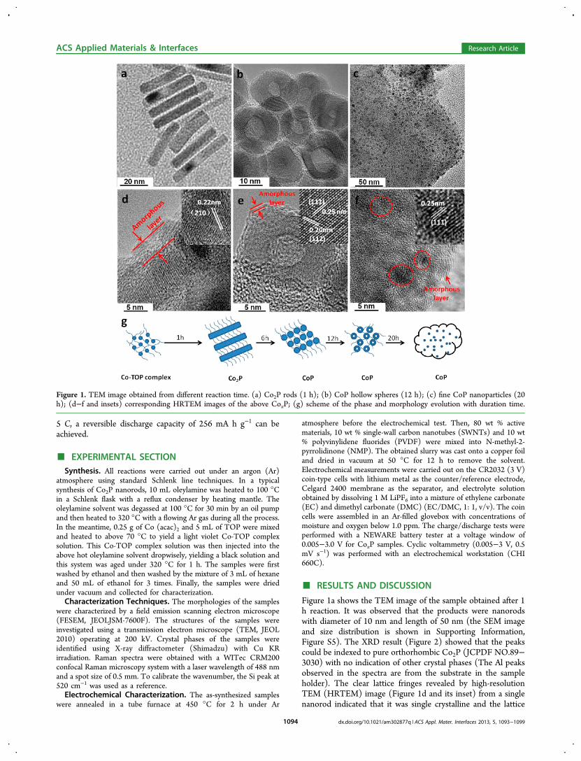
Figure 1a shows the TEM image of the sample obtained after 1h reaction. It was observed that the products were nanorodswith diameter of 10 nm and length of 50 nm (the SEM imageand size distribution is shown in Supporting Information,Figure S5). The XRD result (Figure 2) showed that the peakscould be indexed to pure orthorhombic Co2P (JCPDF NO.89−3030) with no indication of other crystal phases (The Al peaksobserved in the spectra are from the substrate in the sampleholder). The clear lattice fringes revealed by high-resolutionTEM (HRTEM) image (Figure 1d and its inset) from a singlenanorod indicated that it was single crystalline and the lattice
Figure 1. TEM image obtained from different reaction time. (a) Co2P rods (1 h); (b) CoP hollow spheres (12 h); (c) fine CoP nanoparticles (20h); (d−f and insets) corresponding HRTEM images of the above CoxP; (g) scheme of the phase and morphology evolution with duration time.
ACS Applied Materials & Interfaces Research Article
dx.doi.org/10.1021/am302877q | ACS Appl. Mater. Interfaces 2013, 5, 1093−10991094
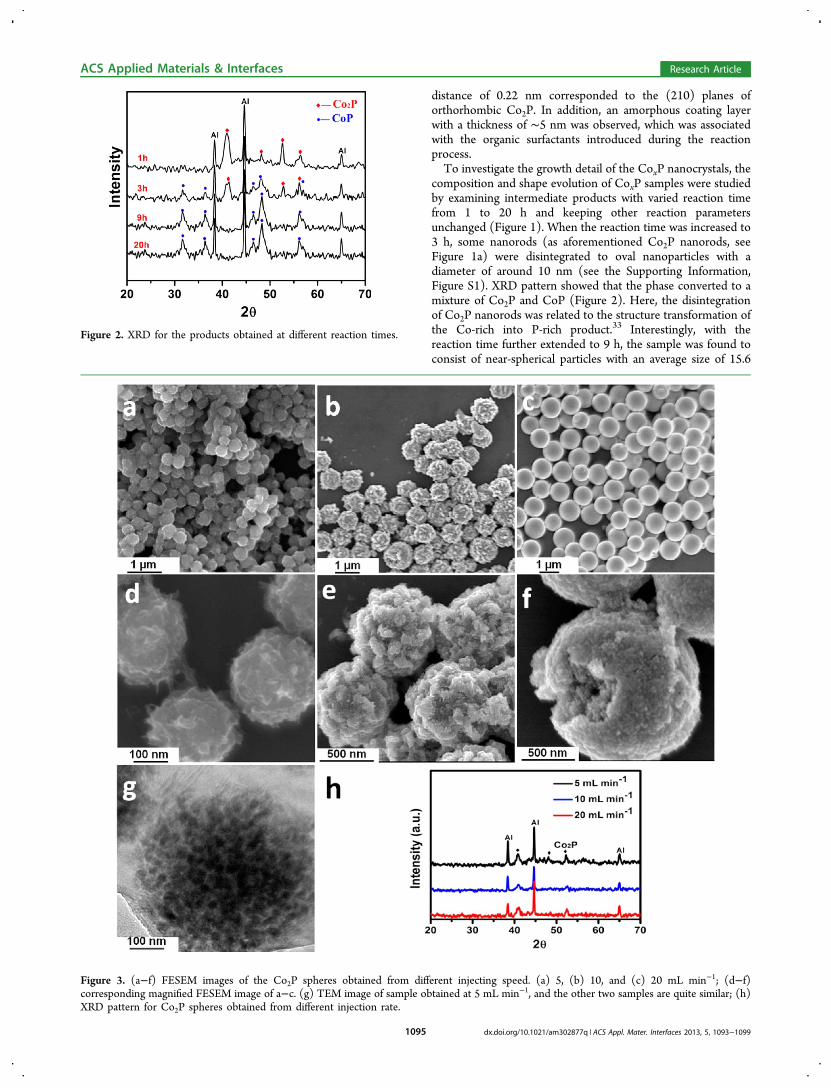
distance of 0.22 nm corresponded to the (210) planes oforthorhombic Co2P. In addition, an amorphous coating layerwith a thickness of ∼5 nm was observed, which was associatedwith the organic surfactants introduced during the reactionprocess.To investigate the growth detail of the CoxP nanocrystals, the
composition and shape evolution of CoxP samples were studiedby examining intermediate products with varied reaction timefrom 1 to 20 h and keeping other reaction parametersunchanged (Figure 1). When the reaction time was increased to3 h, some nanorods (as aforementioned Co2P nanorods, seeFigure 1a) were disintegrated to oval nanoparticles with adiameter of around 10 nm (see the Supporting Information,Figure S1). XRD pattern showed that the phase converted to amixture of Co2P and CoP (Figure 2). Here, the disintegrationof Co2P nanorods was related to the structure transformation ofthe Co-rich into P-rich product.33 Interestingly, with thereaction time further extended to 9 h, the sample was found toconsist of near-spherical particles with an average size of 15.6
Figure 2. XRD for the products obtained at different reaction times.
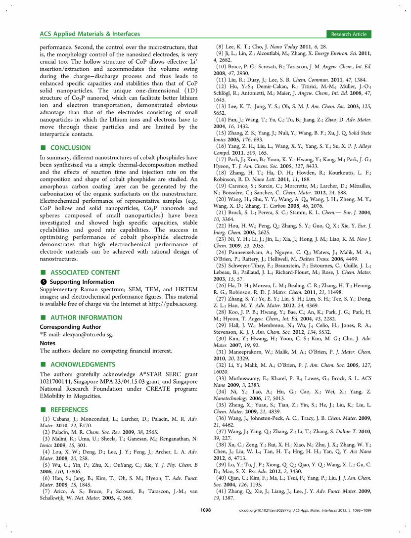
Figure 3. (a−f) FESEM images of the Co2P spheres obtained from different injecting speed. (a) 5, (b) 10, and (c) 20 mL min−1; (d−f)corresponding magnified FESEM image of a−c. (g) TEM image of sample obtained at 5 mL min−1, and the other two samples are quite similar; (h)XRD pattern for Co2P spheres obtained from different injection rate.
ACS Applied Materials & Interfaces Research Article
dx.doi.org/10.1021/am302877q | ACS Appl. Mater. Interfaces 2013, 5, 1093−10991095

nm (Figure 1b and Figure S6 in the Supporting Information forsize distribution). Most of these particles were hollowstructures with the wall thickness of ∼5 nm. XRD resultshowed that these hollow particles were pure orthorhombicCoP (JCPDF No. 65−1474) without any detectable impurityphases (Figure 2). It appeared that the hollow CoP particlesevolved from solid particles (see the Supporting Information,Figure S1) through the nanoscale Kirkendall effect, in whichthe diffusion of Co in the core crossing the preformed CoPlayer was faster than that of P atoms formed by thedecomposition of TOP near the interface at enough hightemperature.34−36 The regular lattice fringe displayed inHRTEM image (Figure 1e) indicated that these hollowparticles were single crystalline and the observed inter latticespacings of 0.25 and 0.20 nm correspond to the (111) and(112) planes of CoP, respectively. It also showed in HRTEMthat these hollow nanoparticles were encapsulated into anamorphous layer (thickness of around 1−2 nm) similar as thatobserved for the Co2P nanorods. To convert this coating layerinto carbon, these CoP nanoparticles were annealed at 450 °Cunder Ar for 2 h. The structure and the amorphous layer ofCoP hollow particles retained after annealing (see theSupporting Information, Figure S2). To verify the nature ofthis amorphous layer, Raman characterization was carried out(see the Supporting Information, Figure S4). The signatures ofG band (e.g., ∼1580 cm−1) and a D1 band (e.g., ∼1340 cm−1)indicated the existence of carbon, which was poorly crystallizedand was similar as that reported for carbon formed bycarbonization of organic surfactants.37,38 Interestingly, whenthe reaction time was further increased to 20 h, the hollowparticles disappeared and smaller nanoparticles with diameterof ∼4 nm formed (see Figure S8 in the Supporting
Information). These fine nanoparticles were embedded in anamorphous framework (Figure 1c, the red circles indicate grainsof nanoparticle). The XRD pattern (Figure 2) was still indexedto orthorhombic CoP phase (JCPDF No. 65−1474). HRTEMimage (Figure 1e) showed that they are single crystalline, andthe lattice spacing between the adjacent planes is 0.25 nm,corresponding to the (111) planes of CoP. The overalldescription of the shape and phase evolution at differentreaction times is illustrated in Figure 1g.Except for the reaction time, the injection rate in the thermal-
decomposition method also played a critical role in affecting thenucleation and growth process of nanocrystal and would finallylead to different composition and morphologies.17,32,39,40 Asmentioned before, uniform Co2P nanorods formed when theCo-TOP complex was added dropwisely (the injection rate was1 mL/min) into the hot oleylamine solution (Figure 1a). Whenslightly increasing the injection rate to 5 mL min−1, we foundthat spheres with diameter around 200 nm were generated(Figure 3a). From the high-magnification SEM and TEMimages, it was observed that these Co2P spheres were mainlycomposed of ∼25 nm nanoparticles (Figure 3d, g). Thediameter of as-formed spheres increased to around 500 nm(Figure 3b, e) and 1 μm (Figure 3c, f) when the injecting speedwas accelerated to 10 and 20 mL min−1, respectively. The XRDpatterns (Figure 3h) revealed that these spheres obtained atdifferent injection rates with reaction time of 1 h were Co2P(JCPDF NO.89−3030). A formation mechanism for thesespheres was proposed.41,42 When the Co-TOP complex wasinjected very fast, large amount of nuclei formed in the solution,reaching the critical point of nucleation promptly. Some of thenucleated particles needed to aggregate further in order toreduce the oversaturated nuclei concentration in a short time.
Figure 4. (a) Cyclic voltammograms (CVs) of the first three cycles of typical CoP hollow particles obtained between 0.005 and 3.0 V at a scan rateof 0.5 mv s−1. (b) The charge/discharge voltage profiles of hollow CoP nanoparticles between 0.005 and 3 V (vs Li+/Li) at a current density of 0.2 C;(c) cycling performance of CoP hollow and solid nanoparticles between 0.005 and 3 V (vs Li+/Li) at 0.2 C; (d) comparison of charge and dischargecapacities of the two electrodes at various current rates.
ACS Applied Materials & Interfaces Research Article
dx.doi.org/10.1021/am302877q | ACS Appl. Mater. Interfaces 2013, 5, 1093−10991096

Besides, as most of TOP was consumed during the nucleationprocess, their capping effect to direct growth of one-dimensional (1D) structure may become less significant inthe later growth process. Instead, weakly adsorbed oleylamineplayed a dominant role and smooth spheres composed ofuniform nanoparticles were formed.For electrochemical characterization, we first investigated the
Li storage property of CoP hollow nanoparticles. Forcomparison purpose, solid CoP nanoparticles, prepared bytuning the volume ratio of TOP to oleylamine (see theSupporting Information, Figure S3 and S7, for detailedprocedure and characterization results), were also examined.The electrochemical characterization of the samples wasconducted based on a Swagelok-type cell with Li metal as thecounter electrode.43 For electrode preparation, both CoPsamples were annealed at 450 °C for 2 h under Ar atmosphereto get similar carbon coated nanostructures shown in theSupporting Information Figure S3c.A representative cyclic voltammograms (CV) of the hollow
CoP nanoparticle electrodes were obtained (Figure 4a) at ascan rate of 0.5 mV s−1 between 0.005−3.0 V (vs Li+/Li) forthe first three discharge/charge cycles. During the first cycledischarge, a sharp peak at around 1.0 V is related to theconversion reaction: CoP + 3 Li+ + 3 e− → Co + Li3P.
44 Inaddition, a small peak at 0.6 V is observed, which correspondsto the reaction of CoP + Li+ + e− → LiP + Co.44 The broadpeak appeared at 0.5 V is attributed to some irreversiblereaction including the formation of solid electrolyte interphase(SEI) layer,45,46 which is missing in subsequent charge/discharge cycles. The oxidation peaks, located at about 2.7and 1.5 V, can be attributed to the decomposition of SEI layerand Li3P (Li3P → LiP + 2 Li+ + 2e−), respectively. Theelectrochemical process extended to further cycles can becharacterized as a redox reaction between Li3P and LiP: Li3P↔LiP + 2 Li+ + 2e−.47 The second and third cycles manifestidentical behavior with position and area of cathodic and anodicpeaks remaining almost unchanged, indicating good reversi-bility and high Coulombic efficiency. The charge−dischargevoltage profiles of the first three cycles were examined (Figure4b) between 0.005 and 3 V at a current density of 89 mA g−1
(0.2 C, and 1 C equals to 890 mA g−1). The first dischargecapacity for hollow CoP particles was 1556 mA h g−1 and thecorresponding charge capacity was 759 mA h g−1. Compared tothe theoretical capacity of CoP (894 mA h g−1), these extracapacities were mainly resulted from the formation of a SEIlayer during the first discharging process, as reported in theliteratures.39,46 This irreversible capacity loss has been widelyreported for the metal phosphide electrodes, which isassociated with the formation of an SEI layer.19,48,49 Duringthe second cycle, the CoP hollow particle electrode delivered adischarge capacity of 780 mA h g−1 and a charge capacity of 707mA h g−1, corresponding to a high Coulombic efficiency of90.6%.Stable cyclic performance of electrode is also important for
practical application of LIB. Figure 4c shows the charge/discharge cycling response of CoP hollow particles at a charge/discharge rate of 0.2 C. The hollow CoP particles depict adischarge capacity of 630 mA h g−1 during the 100th cycle,which is 83.3% of the second-cycle discharge capacity. For thesolid CoP electrode, a discharge capacity of only 480 mA h g−1
was delivered during the 100th cycle. The cycling performanceof CoP electrodes at different charge/discharge rates isevaluated (Figure 4d). With increased C rates, the discharge
capacity for all samples decreased gradually, indicating thediffusion-controlled kinetic process. More specifically, the CoPhollow electrode depicts ninth-cycle discharge capacities of 525,440, 352, 314, 256 mA h g−1 at 0.3, 0.5, 1, 3, and 5 C,respectively. After the charge/discharge rate was reduced to 0.3C, the discharge capacity could recover back to 510 mA h g−1.For CoP solid particle elctrode, it depicts ninth-cycle dischargecapacities of only 549, 396, 294, 252, and 208 mA h g−1 at 0.3,0.5, 1, 3, and 5 C, respectively, which is much lower than that ofhollow particles.We also compared the Li storage properties of annealed
Co2P nanorods (shown in Figure 1a) and nanospherescomposed of small nanoparticles (shown in Figure 3a). Thecyclic voltammogram (CV) of Co2P nanorods is plotted (seethe Supporting Information, Figure S9). During the first cycledischarge, the reduction peak locates at 1.1 V, whichcorresponds to the reaction of Co2P + 3 Li+ + 3 e− → 2 Co+ Li3P.
44 The broad peak at 0.5 V is attributed to someirreversible reaction including the formation of solid electrolyteinterphase (SEI) layer.45,46 The oxidation peaks located ataround 2.7 and 1.5 V, which are attributed to thedecomposition of SEI and Li3P (Li3P → LiP + 2 Li+ + 2e−),respectively. The charge−discharge voltage profiles of the firstthree cycles for Co2P nanorods and spheres (see Figures S10and S11 in the Supporting Information) tested between 0.005and 3 V at a current density of 54 mA g−1 (0.2 C, and 1 Cequals to 540 mA g−1) showed quite similar behavior. For Co2Pnanorods, the first discharge capacity was 1300 mA h g−1 andthe corresponding charge capacity was 600 mA h g−1. Duringthe second cycle, the electrode delivered a discharge capacity of660 mA h g−1 and a charge capacity of 591 mAh g−1,corresponding to a high Coulombic efficiency of 89.5%. Thecharge/discharge cycling performance of Co2P electrodes wasalso evaluated (see the Supporting Information, Figure S12).The Co2P nanorods depict a discharge capacity of 527 mA hg−1 during the 100th-cycle, which is 89.1% of the second-cycledischarge capacity. For the Co2P spheres, a discharge capacityof only 323 mA h g−1 is delivered during the 100th cycle. Whencycling the Co2P electrodes at different charge/discharge rates(see the Supporting Information, Figure S13), the Co2Pnanorods depict ninth-cycle discharge capacities of 490, 385,300, 250, and 204 mA h g−1 at 0.3, 0.5, 1, 3, and 5 C,respectively. After the charge/discharge rate was reduced to 0.3C, the discharge capacity could recover back to 410 mA h g−1.The Co2P spheres depict ninth-cycle discharge capacities ofonly 320, 270, 200, 198, 140 mA h g−1 at 0.3, 0.5, 1, 3, 5 C,respectively, which are lower than that of nanorods.Samples fabricated in this work showed considerable Li
storage property, especially for the CoP hollow particles, whichshowed better performance than that of CoxP electrodesreported in literatures.44,45 For example, for the CoP preparedby ball milling process,44 the capacity retained after the initialcycle was around 500 mA h g−1, but this value rapidly droppedto around 350 mA h g−1 within the first 10 cycles. Moresignificantly, when the Co−P electrode cycled at large currentdensity (e.g., 1000 mA g−1, around 3 C), only a capacity of 240mA h g−1 can be achieved in literature,50 lower than the 310mA h g−1 obtained from hollow CoP.Such considerable optimization in Li storage performance
mainly comes from two aspects. First, as we mentioned before,the carbon shell or network obtained after annealing processcan largely increase the electrical conductivity and effectivelybuffer the volume change, leading to highly stable cycling
ACS Applied Materials & Interfaces Research Article
dx.doi.org/10.1021/am302877q | ACS Appl. Mater. Interfaces 2013, 5, 1093−10991097
performance. Second, the control over the microstructure, thatis, the morphology control of the nanosized electrodes, is verycrucial too. The hollow structure of CoP allows effective Li+
insertion/extraction and accommodates the volume swingduring the charge−discharge process and thus leads toenhanced specific capacities and stabilities than that of CoPsolid nanoparticles. The unique one-dimensional (1D)structure of Co2P nanorod, which can facilitate better lithiumion and electron transportation, demonstrated obviousadvantage than that of the electrodes consisting of smallnanoparticles in which the lithium ions and electrons have tomove through these particles and are limited by theinterparticle contacts.
■ CONCLUSIONIn summary, different nanostructures of cobalt phosphides havebeen synthesized via a simple thermal-decomposition methodand the effects of reaction time and injection rate on thecomposition and shape of cobalt phosphides are studied. Anamorphous carbon coating layer can be generated by thecarbonization of the organic surfactants on the nanostructure.Electrochemical performance of representative samples (e.g.,CoP hollow and solid nanoparticles, Co2P nanorods andspheres composed of small nanoparticles) have beeninvestigated and showed high specific capacities, stablecyclabilities and good rate capabilities. The success inoptimizing performance of cobalt phosphide electrodedemonstrates that high electrochemical performance ofelectrode materials can be achieved with rational design ofnanostructures.
■ ASSOCIATED CONTENT*S Supporting InformationSupplementary Raman spectrum; SEM, TEM, and HRTEMimages; and electrochemical performance figures. This materialis available free of charge via the Internet at http://pubs.acs.org.
■ AUTHOR INFORMATIONCorresponding Author*E-mail: [email protected] authors declare no competing financial interest.
■ ACKNOWLEDGMENTSThe authors gratefully acknowledge A*STAR SERC grant1021700144, Singapore MPA 23/04.15.03 grant, and SingaporeNational Research Foundation under CREATE program:EMobility in Megacities.
■ REFERENCES(1) Cabana, J.; Monconduit, L.; Larcher, D.; Palacín, M. R. Adv.Mater. 2010, 22, E170.(2) Palacın, M. R. Chem. Soc. Rev. 2009, 38, 2565.(3) Malini, R.; Uma, U.; Sheela, T.; Ganesan, M.; Renganathan, N.Ionics 2009, 15, 301.(4) Lou, X. W.; Deng, D.; Lee, J. Y.; Feng, J.; Archer, L. A. Adv.Mater. 2008, 20, 258.(5) Wu, C.; Yin, P.; Zhu, X.; OuYang, C.; Xie, Y. J. Phy. Chem. B2006, 110, 17806.(6) Han, S.; Jang, B.; Kim, T.; Oh, S. M.; Hyeon, T. Adv. Funct.Mater. 2005, 15, 1845.(7) Arico, A. S.; Bruce, P.; Scrosati, B.; Tarascon, J.-M.; vanSchalkwijk, W. Nat. Mater. 2005, 4, 366.
(8) Lee, K. T.; Cho, J. Nano Today 2011, 6, 28.(9) Ji, L.; Lin, Z.; Alcoutlabi, M.; Zhang, X. Energy Environ. Sci. 2011,4, 2682.(10) Bruce, P. G.; Scrosati, B.; Tarascon, J.-M. Angew. Chem., Int. Ed.2008, 47, 2930.(11) Liu, R.; Duay, J.; Lee, S. B. Chem. Commun. 2011, 47, 1384.(12) Hu, Y.-S.; Demir-Cakan, R.; Titirici, M.-M.; Muller, J.-O.;Schlogl, R.; Antonietti, M.; Maier, J. Angew. Chem., Int. Ed. 2008, 47,1645.(13) Lee, K. T.; Jung, Y. S.; Oh, S. M. J. Am. Chem. Soc. 2003, 125,5652.(14) Fan, J.; Wang, T.; Yu, C.; Tu, B.; Jiang, Z.; Zhao, D. Adv. Mater.2004, 16, 1432.(15) Zhang, Z. S.; Yang, J.; Nuli, Y.; Wang, B. F.; Xu, J. Q. Solid StateIonics 2005, 176, 693.(16) Yang, Z. H.; Liu, L.; Wang, X. Y.; Yang, S. Y.; Su, X. P. J. AlloysCompd. 2011, 509, 165.(17) Park, J.; Koo, B.; Yoon, K. Y.; Hwang, Y.; Kang, M.; Park, J. G.;Hyeon, T. J. Am. Chem. Soc. 2005, 127, 8433.(18) Zhang, H. T.; Ha, D. H.; Hovden, R.; Kourkoutis, L. F.;Robinson, R. D. Nano Lett. 2011, 11, 188.(19) Carenco, S.; Surcin, C.; Morcrette, M.; Larcher, D.; Mezailles,N.; Boissiere, C.; Sanchez, C. Chem. Mater. 2012, 24, 688.(20) Wang, H.; Shu, Y. Y.; Wang, A. Q.; Wang, J. H.; Zheng, M. Y.;Wang, X. D.; Zhang, T. Carbon 2008, 46, 2076.(21) Brock, S. L.; Perera, S. C.; Stamm, K. L. Chem. Eur. J. 2004,10, 3364.(22) Hou, H. W.; Peng, Q.; Zhang, S. Y.; Guo, Q. X.; Xie, Y. Eur. J.Inorg. Chem. 2005, 2625.(23) Ni, Y. H.; Li, J.; Jin, L.; Xia, J.; Hong, J. M.; Liao, K. M. New J.Chem. 2009, 33, 2055.(24) Panneerselvam, A.; Nguyen, C. Q.; Waters, J.; Malik, M. A.;O’Brien, P.; Raftery, J.; Helliwell, M. Dalton Trans. 2008, 4499.(25) Schweyer-Tihay, F.; Braunstein, P.; Estournes, C.; Guille, J. L.;Lebeau, B.; Paillaud, J. L.; Richard-Plouet, M.; Rose, J. Chem. Mater.2003, 15, 57.(26) Ha, D. H.; Moreau, L. M.; Bealing, C. R.; Zhang, H. T.; Hennig,R. G.; Robinson, R. D. J. Mater. Chem. 2011, 21, 11498.(27) Zhang, S. Y.; Ye, E. Y.; Liu, S. H.; Lim, S. H.; Tee, S. Y.; Dong,Z. L.; Han, M. Y. Adv. Mater. 2012, 24, 4369.(28) Koo, J. P. B.; Hwang, Y.; Bae, C.; An, K.; Park, J. G.; Park, H.M.; Hyeon, T. Angew. Chem., Int. Ed. 2004, 43, 2282.(29) Hall, J. W.; Membreno, N.; Wu, J.; Celio, H.; Jones, R. A.;Stevenson, K. J. J. Am. Chem. Soc. 2012, 134, 5532.(30) Kim, Y.; Hwang, H.; Yoon, C. S.; Kim, M. G.; Cho, J. Adv.Mater. 2007, 19, 92.(31) Maneeprakorn, W.; Malik, M. A.; O’Brien, P. J. Mater. Chem.2010, 20, 2329.(32) Li, Y.; Malik, M. A.; O’Brien, P. J. Am. Chem. Soc. 2005, 127,16020.(33) Muthuswamy, E.; Kharel, P. R.; Lawes, G.; Brock, S. L. ACSNano 2009, 3, 2383.(34) Ni, Y.; Tao, A.; Hu, G.; Cao, X.; Wei, X.; Yang, Z.Nanotechnology 2006, 17, 5013.(35) Zheng, X.; Yuan, S.; Tian, Z.; Yin, S.; He, J.; Liu, K.; Liu, L.Chem. Mater. 2009, 21, 4839.(36) Wang, J.; Johnston-Peck, A. C.; Tracy, J. B. Chem. Mater. 2009,21, 4462.(37) Wang, J.; Yang, Q.; Zhang, Z.; Li, T.; Zhang, S. Dalton T. 2010,39, 227.(38) Xu, C.; Zeng, Y.; Rui, X. H.; Xiao, N.; Zhu, J. X.; Zhang, W. Y.;Chen, J.; Liu, W. L.; Tan, H. T.; Hng, H. H.; Yan, Q. Y. Acs Nano2012, 6, 4713.(39) Lu, Y.; Tu, J. P.; Xiong, Q. Q.; Qiao, Y. Q.; Wang, X. L.; Gu, C.D.; Mao, S. X. Rsc Adv. 2012, 2, 3430.(40) Qian, C.; Kim, F.; Ma, L.; Tsui, F.; Yang, P.; Liu, J. J. Am. Chem.Soc. 2004, 126, 1195.(41) Zhang, Q.; Xie, J.; Liang, J.; Lee, J. Y. Adv. Funct. Mater. 2009,19, 1387.
ACS Applied Materials & Interfaces Research Article
dx.doi.org/10.1021/am302877q | ACS Appl. Mater. Interfaces 2013, 5, 1093−10991098
(42) Park, J.; Joo, J.; Kwon, S. G.; Jang, Y.; Hyeon, T. Angew. Chem.,Int. Ed. 2007, 46, 4630.(43) Lu, Z. Y.; Zhu, J. X.; Sim, D. H.; Zhou, W. W.; Ship, W. H.;Hng, H. H.; Yan, Q. Y. Chem. Mater. 2011, 23, 5293.(44) Zhang, Z.; Yang, J.; Nuli, Y.; Wang, B.; Xu, J. Solid State Ionics2005, 176, 693.(45) Lopez, M. C.; Ortiz, G. F.; Tirado, J. L. J. Electrochem. Soc. 2012,159, A1253.(46) Lu, Y.; Tu, J. P.; Xiang, J. Y.; Wang, X. L.; Zhang, J.; Mai, Y. J.;Mao, S. X. J. Phy. Chem. C 2011, 115, 23760.(47) Lucas, I.; Perez, L.; Aroca, C.; Sanchez, P.; Lopez, E.; Sanchez,M. C. J. Magn. Magn. Mater. 2005, 290−291 (Part 2), 1513.(48) Boyanov, S.; Zitoun, D.; Menetrier, M.; Jumas, J. C.; Womes,M.; Monconduit, L. J. Phy. Chem. C 2009, 113, 21441.(49) Pralong, V.; Souza, D. C. S.; Leung, K. T.; Nazar, L. F.Electrochem. Commun. 2002, 4, 516.(50) Cao, Y.; Zhou, W.; Li, X.; Ai, X.; Gao, X.; Yang, H. Electrochim.Acta 2006, 51, 4285.
ACS Applied Materials & Interfaces Research Article
dx.doi.org/10.1021/am302877q | ACS Appl. Mater. Interfaces 2013, 5, 1093−10991099