The Data Vortex Optical Packet Switched Interconnection Network
Upload
khangminh22Category
view
1download
0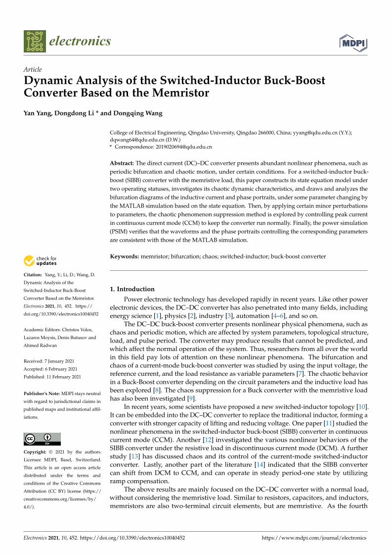
electronics
Article
Dynamic Analysis of the Switched-Inductor Buck-BoostConverter Based on the Memristor
Yan Yang, Dongdong Li * and Dongqing Wang
Citation: Yang, Y.; Li, D.; Wang, D.
Dynamic Analysis of the
Switched-Inductor Buck-Boost
Converter Based on the Memristor.
Electronics 2021, 10, 452. https://
doi.org/10.3390/electronics10040452
Academic Editors: Christos Volos,
Lazaros Moysis, Denis Butusov and
Ahmed Radwan
Received: 7 January 2021
Accepted: 6 February 2021
Published: 11 February 2021
Publisher’s Note: MDPI stays neutral
with regard to jurisdictional claims in
published maps and institutional affil-
iations.
Copyright: © 2021 by the authors.
Licensee MDPI, Basel, Switzerland.
This article is an open access article
distributed under the terms and
conditions of the Creative Commons
Attribution (CC BY) license (https://
creativecommons.org/licenses/by/
4.0/).
College of Electrical Engineering, Qingdao University, Qingdao 266000, China; [email protected] (Y.Y.);[email protected] (D.W.)* Correspondence: [email protected]
Abstract: The direct current (DC)–DC converter presents abundant nonlinear phenomena, such asperiodic bifurcation and chaotic motion, under certain conditions. For a switched-inductor buck-boost (SIBB) converter with the memristive load, this paper constructs its state equation model undertwo operating statuses, investigates its chaotic dynamic characteristics, and draws and analyzes thebifurcation diagrams of the inductive current and phase portraits, under some parameter changing bythe MATLAB simulation based on the state equation. Then, by applying certain minor perturbationsto parameters, the chaotic phenomenon suppression method is explored by controlling peak currentin continuous current mode (CCM) to keep the converter run normally. Finally, the power simulation(PSIM) verifies that the waveforms and the phase portraits controlling the corresponding parametersare consistent with those of the MATLAB simulation.
Keywords: memristor; bifurcation; chaos; switched-inductor; buck-boost converter
1. Introduction
Power electronic technology has developed rapidly in recent years. Like other powerelectronic devices, the DC–DC converter has also penetrated into many fields, includingenergy science [1], physics [2], industry [3], automation [4–6], and so on.
The DC–DC buck-boost converter presents nonlinear physical phenomena, such aschaos and periodic motion, which are affected by system parameters, topological structure,load, and pulse period. The converter may produce results that cannot be predicted, andwhich affect the normal operation of the system. Thus, researchers from all over the worldin this field pay lots of attention on these nonlinear phenomena. The bifurcation andchaos of a current-mode buck-boost converter was studied by using the input voltage, thereference current, and the load resistance as variable parameters [7]. The chaotic behaviorin a Buck-Boost converter depending on the circuit parameters and the inductive load hasbeen explored [8]. The chaos suppression for a Buck converter with the memristive loadhas also been investigated [9].
In recent years, some scientists have proposed a new switched-inductor topology [10].It can be embedded into the DC–DC converter to replace the traditional inductor, forming aconverter with stronger capacity of lifting and reducing voltage. One paper [11] studied thenonlinear phenomena in the switched-inductor buck-boost (SIBB) converter in continuouscurrent mode (CCM). Another [12] investigated the various nonlinear behaviors of theSIBB converter under the resistive load in discontinuous current mode (DCM). A furtherstudy [13] has discussed chaos and its control of the current-mode switched-inductorconverter. Lastly, another part of the literature [14] indicated that the SIBB convertercan shift from DCM to CCM, and can operate in steady period-one state by utilizingramp compensation.
The above results are mainly focused on the DC–DC converter with a normal load,without considering the memristive load. Similar to resistors, capacitors, and inductors,memristors are also two-terminal circuit elements, but are memristive. As the fourth
Electronics 2021, 10, 452. https://doi.org/10.3390/electronics10040452 https://www.mdpi.com/journal/electronics

Electronics 2021, 10, 452 2 of 10
circuit element, the memristor has become an important research field, due to its wideapplication, such as in the fields of memory [15–18], artificial intelligence computers [19,20],and electronic engineering [21–32]. In the electronic engineering field, memristor has beenused in logic-based digital operations [21,22] and analog circuits [23–26]; memristors alsohave been used in reconfigurable analog circuits as programmable elements [27,28], as filterelements for signal processing [29,30], and in power converters as memristive loads [31,32].
Recently, replacing the traditional load in boost and buck-boost converters with thememristors, and analyzing the nonlinear dynamic characteristics of converters, has becomea hot topic [33]. However, few researchers consider the dynamic characteristics of theSIBB converter with the memristive load. The purpose of this paper is to investigate thebifurcation and chaotic behavior of the SIBB converter with the memristive load whenthe peak current changes. Furthermore, the harmful bifurcation and chaotic behavior aresuppressed by controlling the peak current.
2. Working Principle of the Converter and the Memristor
Terminology description is given as follows.
SIBB Switched-inductor buck-boostCCM Continuous current modeDCM Discontinuous current modeDC Direct currentPSIM Power simulationMATLAB Matrix laboratoryPV PhotovoltaicBAM Bidirectional associative memoryAMS Analog mixed signalCNN Cellular nonlinear/neural networkCT Continuous-timeFIR Finite impulse response
2.1. Working Principle of the Converter
The current-mode-controlled SIBB converter is a kind of DC–DC converter controlledby the inductive current. It is formed by applying a switched-inductor structure to thetraditional converter. Its basic circuit is shown in Figure 1.
Figure 1. The switched-inductor buck-boost (SIBB) converter under peak current mode.
The feedback loop consists of an RS flip-flop and a comparator. An RS flip-flop hasa reset input R and a set input S, as well as an output Q. The output Q directly controlsthe state of the switch S. The set input S comes from the clock, while the reset input Rcomes from the comparison of the reference current Ire f and the inductive current i1 in thecomparator. This converter has two operating modes: continuous current mode (CCM)and discontinuous current mode (DCM). This paper studies the dynamic characteristics ofthe converter in CCM. In this mode, the circuit has two statuses, as shown in Figure 2.

Electronics 2021, 10, 452 3 of 10
Figure 2. Circuit statuses in continuous current mode (CCM). (a) Switch S is ON. (b) Switch S is OFF.
To make the analysis easier, let two inductors of the switched-inductor L1 = L2 and i1is approximately equal to i2, and the inductive current i2 can be written as i1. Thus, thesystem with the resistive load can be simplified to a second-order model, and its stateequations are as follows .
x = A1x + B1Vin S is ON.x = A2x + B2Vin S is OFF
(1)
where x = [ i1 u] T is the state vector, Vin is the input voltage, and the coefficient matricesare
A1 =
[0 00 − 1
RC
], B1 =
[1L10
], A2 =
[0 − 1
2L11C − 1
RC
], B2 =
[00
]
2.2. The Simulation Model of the Memristor
About 50 years ago, professor Cai theoretically predicted that the existence of anonlinear, passive, two-terminal electronic element that could describe the relationshipbetween charge and flux, and called it a memristor [34]. Cai also generated the concept ofa generalized memristor. In 2008, the feasibility of memristors was reported in Nature. Thisreport shocked the international electrical and electronic world, and made the theoreticalbasis of circuits more perfect. The memristor was finally unveiled in 2009 after a flurry ofresearch by many scientists. Its symbol is shown in Figure 3.
Figure 3. Symbol of the memristor.
Memristors are similar to resistors, capacitors, and inductors as a nonlinear, passive,two-terminal electronic element. It has two forms: the charge-controlled memristor andthe magnetron-controlled memristor. The relationship between its magnetic flux andaccumulated charge is
M(q) =dϕ(q)
dq(2)
W(ϕ) =dq(ϕ)
dϕ(3)
where M(q) is called memristance and W(ϕ) is called memductance [34].A simulator of the magnetron-controlled memristor is designed by using circuit
elements, as shown in Figure 4.
Electronics 2021, 10, 452 4 of 10
Figure 4. The simulator of the magnetron-controlled memristive load.
Referring to [33], the simulation circuit consists of two operational amplifiers, U1and U2; three resistors, R1, R2, and R0; a capacitor C0; and a multiplier M, which isg = −0.1. In addition, u and i0 are expressed as the input voltage and input current of thesimulation circuit, respectively. According to the volt–ampere relationship of the memristor,u(t) = M(q)i(t) and i(t) = W(ϕ)u(t). The mathematical model of the memristor simulatorcan be obtained as follows:
i0 =1
R0(1 − gv0)u (4)
dv0
dt= − 1
R1C0u − 1
R2C0v0 (5)
3. The Modeling and Simulation3.1. The Modeling of the SIBB Converter with the Memristive Load
We have described the operating principle of the SIBB converter and obtained itsstate equations under the resistive load. Now we have replaced the resistive load with thememristive load.
In CCM, the SIBB converter with its memristive load still has two statuses: switch S ison, D0 is off; and switch S is off, D0 is on, as shown in Figure 2. At this time, the voltage onthe capacitor C is the input voltage of the simulation circuit, and i0 is the input current ofthe simulation circuit. The state equations of the system with the memristive load can beobtained as follows: .
x = A1x + B1Vin + Cy S is ON.x = A2x + B2Vin + Cy S is OFF
(6)
where x = [ i1 u v0]T is the state vector; Vin is the input voltage; and y is the product
of two state variables, such that y = uv0. The coefficient matrices are
A1 =
0 0 00 − 1
R0C 0
0 1R1C0
− 1R2C0
, B1 =
1L100
,
C =
0g
R0C
0
, A2 =
0 − 1
2L10
1C − 1
R0C 0
0 1R1C0
− 1R2C0
, B2 =
000
3.2. The Simulation of the SIBB Converter with the Memristive Load
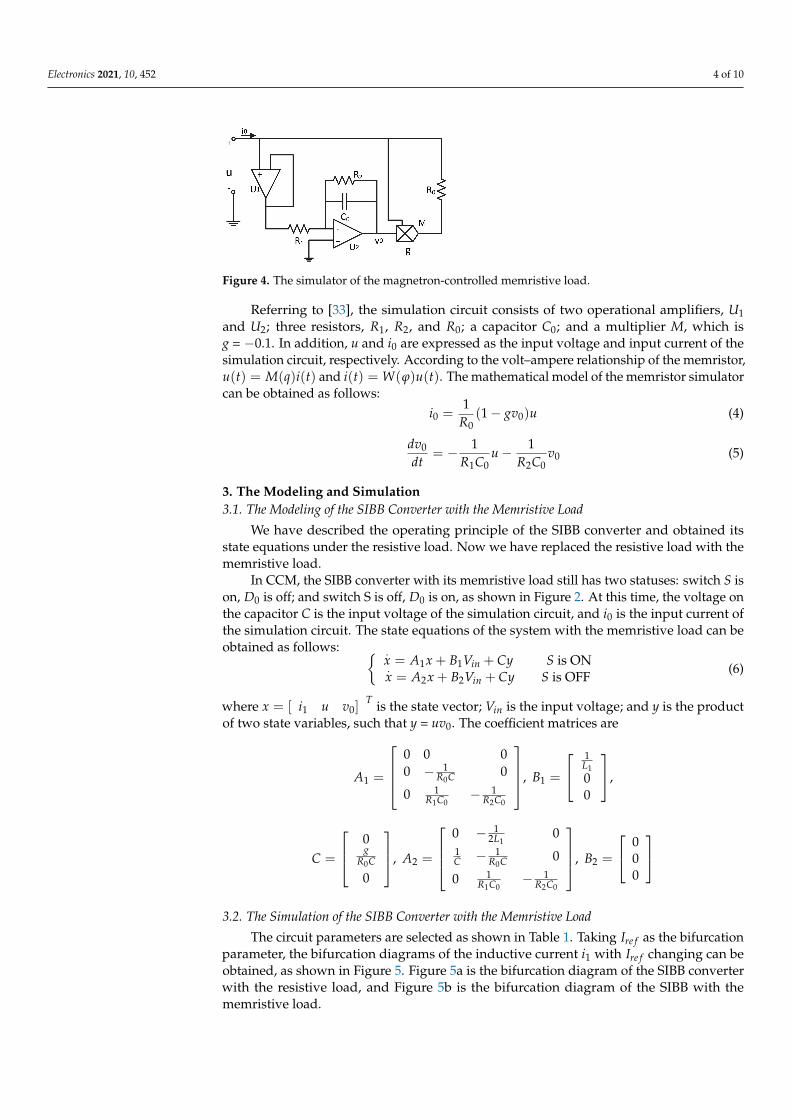
The circuit parameters are selected as shown in Table 1. Taking Ire f as the bifurcationparameter, the bifurcation diagrams of the inductive current i1 with Ire f changing can beobtained, as shown in Figure 5. Figure 5a is the bifurcation diagram of the SIBB converterwith the resistive load, and Figure 5b is the bifurcation diagram of the SIBB with thememristive load.
Electronics 2021, 10, 452 5 of 10
Table 1. The circuit element parameters.
Elements Parameters Values
Voltage Vin 5 VInductor L1, L2 0.1 mHCapacitor C 10 µFCapacitor C0 20 nFResistor R1, R2 1 kΩResistor R, R0 5 Ω
Frequency f 20 kHzMultiplier g −0.1
Figure 5. The bifurcation diagram of inductive current i1 controlled by the reference current Ire f .(a) With the resistive load, (b) With the memristive load.
According to the comparison of the bifurcation diagrams, we can see that the memris-tive load does not affect the bifurcation structure. Both of them have chaos and bifurcationof two-period, four-period, eight-period, etc., but the bifurcation point of the period dou-bling can be moved. The results are listed as follows:
(1) The two-period bifurcation of the converter with the resistive load occurs whenIre f = 3 A, while two-period bifurcation of the converter with the memristive loadoccurs when Ire f = 3.85 A. Therefore the normal working area of the system is widenedunder the memristive load.
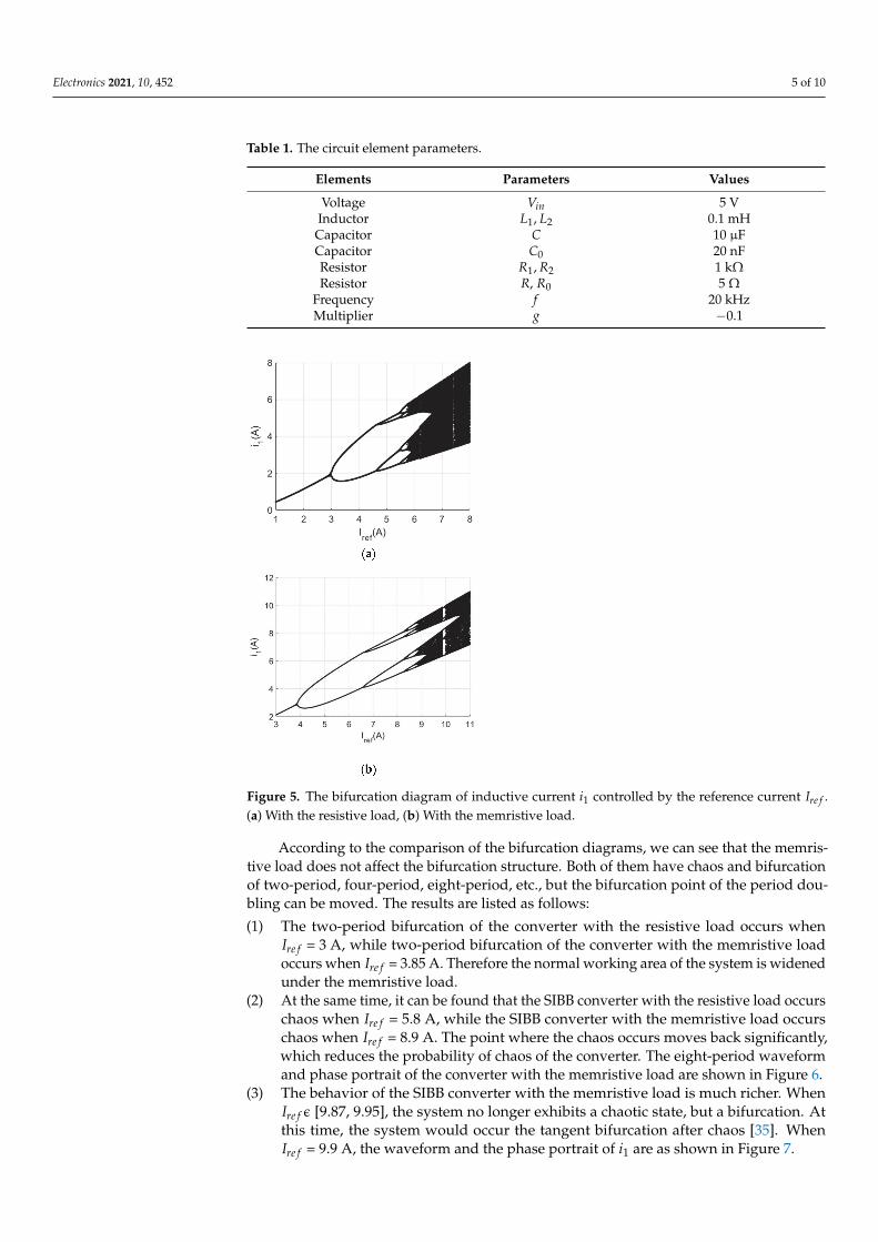
(2) At the same time, it can be found that the SIBB converter with the resistive load occurschaos when Ire f = 5.8 A, while the SIBB converter with the memristive load occurschaos when Ire f = 8.9 A. The point where the chaos occurs moves back significantly,which reduces the probability of chaos of the converter. The eight-period waveformand phase portrait of the converter with the memristive load are shown in Figure 6.
(3) The behavior of the SIBB converter with the memristive load is much richer. WhenIre fε [9.87, 9.95], the system no longer exhibits a chaotic state, but a bifurcation. Atthis time, the system would occur the tangent bifurcation after chaos [35]. WhenIre f = 9.9 A, the waveform and the phase portrait of i1 are as shown in Figure 7.
Electronics 2021, 10, 452 6 of 10
Electronics 2021, 10, x FOR PEER REVIEW 6 of 11
According to the comparison of the bifurcation diagrams, we can see that the memristive load does not affect the bifurcation structure. Both of them have chaos and bifurcation of two-period, four-period, eight-period, etc., but the bifurcation point of the period doubling can be moved. The results are listed as follows:
(1) The two-period bifurcation of the converter with the resistive load occurs when 𝐼 = 3 A, while two-period bifurcation of the converter with the memristive load occurs when 𝐼 = 3.85 A. Therefore the normal working area of the system is widened under the memristive load.
(2) At the same time, it can be found that the SIBB converter with the resistive load occurs chaos when 𝐼 = 5.8 A, while the SIBB converter with the memristive load occurs chaos when 𝐼 = 8.9 A. The point where the chaos occurs moves back significantly, which reduces the probability of chaos of the converter. The eight-period waveform and phase portrait of the converter with the memristive load are shown in Figure 6.
(a) (b)
Figure 6. The waveform and phase portrait of 𝑖 (𝐼 = 8.6 A). (a) The waveform of 𝑖 , (b) The phase portrait of 𝑢 − 𝑖 .
(3) The behavior of the SIBB converter with the memristive load is much richer. When 𝐼 ϵ [9.87, 9.95], the system no longer exhibits a chaotic state, but a bifurcation. At this time, the system would occur the tangent bifurcation after chaos [35]. When 𝐼 = 9.9 A, the waveform and the phase portrait of 𝑖 are as shown in Figure 7.
(a) (b)
Figure 7. The waveform and phase portrait of 𝑖 (𝐼 = 9.9 A). (a) The waveform of 𝑖 , (b) The phase portrait of 𝑢 − 𝑖 .
The bifurcation diagrams of the SIBB converter with the resistive load and memristive load were obtained by MATLAB simulation. Next, the PSIM software was used for simulation to verify the accuracy of the bifurcation and chaotic behavior of the converter with the memristive load.
4. Verification by the PSIM Simulation The PSIM software is used for simulation to verify the accuracy of the bifurcation
and chaotic behavior of the converter with the memristive load. According to the schematic diagram shown in Figure 1, this section builds the simulation model of the system in the PSIM circuit software, as shown in Figure 8. The reference current 𝐼 is selected as the variable, and the parameters of each circuit element are the same as those
Figure 6. The waveform and phase portrait of i1 (Ire f = 8.6 A). (a) The waveform of i1, (b) The phaseportrait of u − i1.
Electronics 2021, 10, x FOR PEER REVIEW 6 of 11
According to the comparison of the bifurcation diagrams, we can see that the memristive load does not affect the bifurcation structure. Both of them have chaos and bifurcation of two-period, four-period, eight-period, etc., but the bifurcation point of the period doubling can be moved. The results are listed as follows:
(1) The two-period bifurcation of the converter with the resistive load occurs when 𝐼 = 3 A, while two-period bifurcation of the converter with the memristive load occurs when 𝐼 = 3.85 A. Therefore the normal working area of the system is widened under the memristive load.
(2) At the same time, it can be found that the SIBB converter with the resistive load occurs chaos when 𝐼 = 5.8 A, while the SIBB converter with the memristive load occurs chaos when 𝐼 = 8.9 A. The point where the chaos occurs moves back significantly, which reduces the probability of chaos of the converter. The eight-period waveform and phase portrait of the converter with the memristive load are shown in Figure 6.
(a) (b)
Figure 6. The waveform and phase portrait of 𝑖 (𝐼 = 8.6 A). (a) The waveform of 𝑖 , (b) The phase portrait of 𝑢 − 𝑖 .
(3) The behavior of the SIBB converter with the memristive load is much richer. When 𝐼 ϵ [9.87, 9.95], the system no longer exhibits a chaotic state, but a bifurcation. At this time, the system would occur the tangent bifurcation after chaos [35]. When 𝐼 = 9.9 A, the waveform and the phase portrait of 𝑖 are as shown in Figure 7.
(a) (b)
Figure 7. The waveform and phase portrait of 𝑖 (𝐼 = 9.9 A). (a) The waveform of 𝑖 , (b) The phase portrait of 𝑢 − 𝑖 .
The bifurcation diagrams of the SIBB converter with the resistive load and memristive load were obtained by MATLAB simulation. Next, the PSIM software was used for simulation to verify the accuracy of the bifurcation and chaotic behavior of the converter with the memristive load.
4. Verification by the PSIM Simulation The PSIM software is used for simulation to verify the accuracy of the bifurcation
and chaotic behavior of the converter with the memristive load. According to the schematic diagram shown in Figure 1, this section builds the simulation model of the system in the PSIM circuit software, as shown in Figure 8. The reference current 𝐼 is selected as the variable, and the parameters of each circuit element are the same as those
Figure 7. The waveform and phase portrait of i1 (Ire f = 9.9 A). (a) The waveform of i1, (b) The phaseportrait of u − i1.
The bifurcation diagrams of the SIBB converter with the resistive load and memristiveload were obtained by MATLAB simulation. Next, the PSIM software was used forsimulation to verify the accuracy of the bifurcation and chaotic behavior of the converterwith the memristive load.
4. Verification by the PSIM Simulation
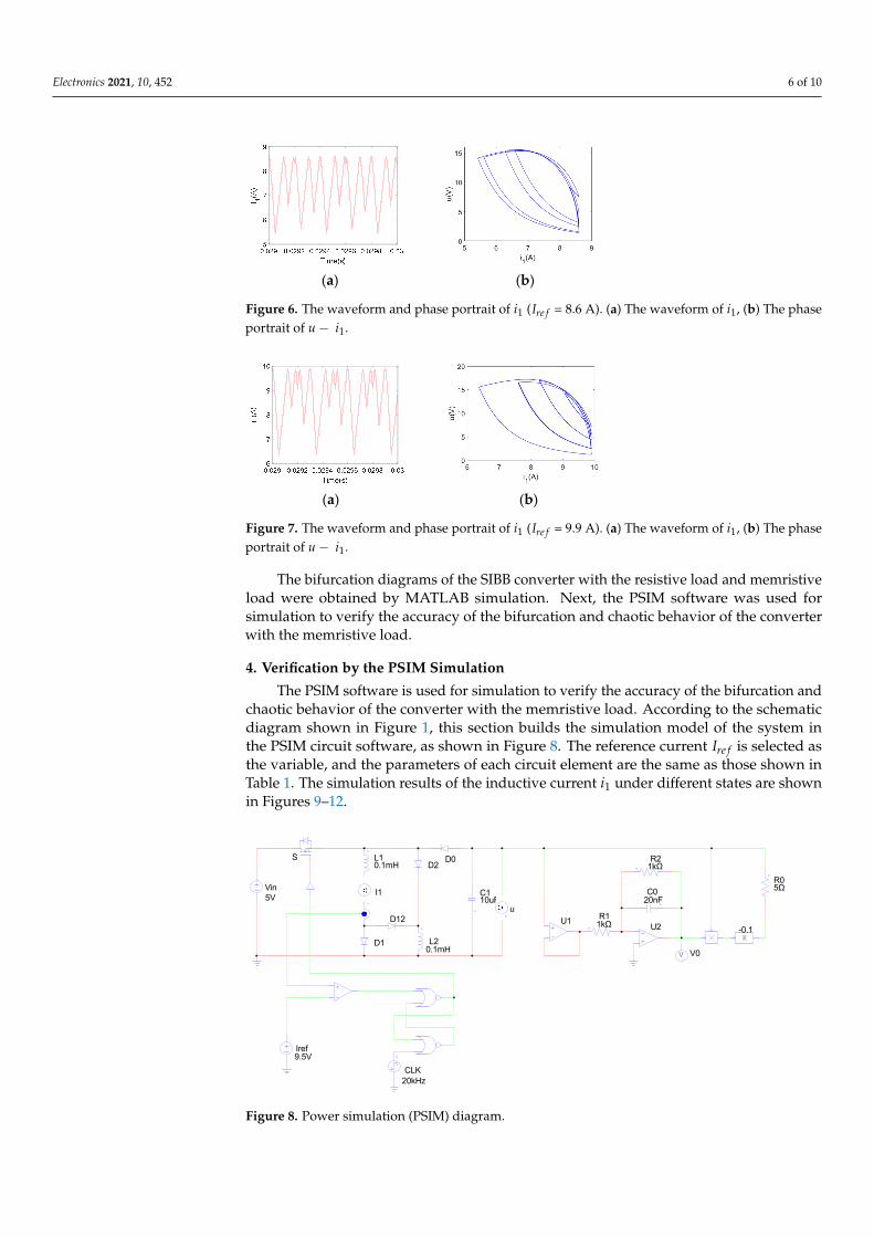
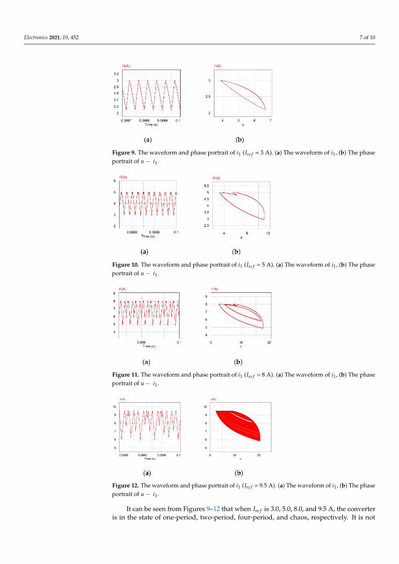
The PSIM software is used for simulation to verify the accuracy of the bifurcation andchaotic behavior of the converter with the memristive load. According to the schematicdiagram shown in Figure 1, this section builds the simulation model of the system inthe PSIM circuit software, as shown in Figure 8. The reference current Ire f is selected asthe variable, and the parameters of each circuit element are the same as those shown inTable 1. The simulation results of the inductive current i1 under different states are shownin Figures 9–12.
Electronics 2021, 10, x FOR PEER REVIEW 7 of 11
shown in Table 1. The simulation results of the inductive current 𝑖 under different states are shown in Figures 9–12.
It can be seen from Figures 9–12 that when 𝐼 is 3.0, 5.0, 8.0, and 9.5 A, the converter is in the state of one-period, two-period, four-period, and chaos, respectively. It is not difficult to see that the simulation results of this PSIM circuit are consistent with those of the MATLAB simulation.
Figure 8. Power simulation (PSIM) diagram.
(a) (b)
Figure 9. The waveform and phase portrait of 𝑖 (𝐼 = 3 A). (a) The waveform of 𝑖 , (b) The phase portrait of 𝑢 − 𝑖 .
(a) (b)
Figure 10. The waveform and phase portrait of 𝑖 (𝐼 = 5 A). (a) The waveform of 𝑖 , (b) The phase portrait of 𝑢 − 𝑖 .
5VVin
0.1mHL1
0.1mHL2
D12
D2
C110uF
S D0
I1
D1
u
Iref9.5V
CLK20kHz
R11kΩ
1kΩR2
C020nF
V V0
K-0.1
5ΩR0
U2U1
Figure 8. Power simulation (PSIM) diagram.
Electronics 2021, 10, 452 7 of 10
Figure 9. The waveform and phase portrait of i1 (Ire f = 3 A). (a) The waveform of i1, (b) The phaseportrait of u − i1.
Figure 10. The waveform and phase portrait of i1 (Ire f = 5 A). (a) The waveform of i1, (b) The phaseportrait of u − i1.
Figure 11. The waveform and phase portrait of i1 (Ire f = 8 A). (a) The waveform of i1, (b) The phaseportrait of u − i1.
Figure 12. The waveform and phase portrait of i1 (Ire f = 9.5 A). (a) The waveform of i1, (b) The phaseportrait of u − i1.
It can be seen from Figures 9–12 that when Ire f is 3.0, 5.0, 8.0, and 9.5 A, the converteris in the state of one-period, two-period, four-period, and chaos, respectively. It is not

Electronics 2021, 10, 452 8 of 10
difficult to see that the simulation results of this PSIM circuit are consistent with those ofthe MATLAB simulation.
5. Suppression of the Chaos
The resonant parametric perturbation method takes advantage of the characteristicsthat the chaotic state is very sensitive to—the minor perturbation of the parameters. Byapplying certain minor perturbation to the parameters, the system can be controlled fromthe chaotic state to the stable one-period state.
According to the above results of the PSIM simulation, the SIBB converter with thememristive load is in a chaotic state when Ire f = 9.5 A. The resonant parametric perturbationmethod is used to control the chaos of the SIBB converter on this condition.
It is relatively simple that Ire f is used as the control parameter. Using Ire f 2 = Ire f + Ire f 1to replace Ire f , according to this method, where Ire f 1 = Asin(2π f t + ϕ) and f is theswitching frequency (f = 20 kHz). Referring to [13], let A equal 0.3 and ϕ = 1.2 rad. Aminor perturbation is added when t = 0.05 s. The circuit diagram of the controller isshown in Figure 13b, compared with the original simple controller in Figure 13a. Then, thewaveform of u and i1, as well as the phase portrait of u − i1 under the minor perturbation,are obtained, as shown in Figure 14.
Electronics 2021, 10, x FOR PEER REVIEW 8 of 11
(a) (b)
Figure 11. The waveform and phase portrait of 𝑖 (𝐼 = 8 A). (a) The waveform of 𝑖 , (b) The phase portrait of 𝑢 − 𝑖 .
(a) (b)
Figure 12. The waveform and phase portrait of 𝑖 (𝐼 = 9.5 A). (a) The waveform of 𝑖 , (b) The phase portrait of 𝑢 − 𝑖 .
5. Suppression of the Chaos The resonant parametric perturbation method takes advantage of the characteristics
that the chaotic state is very sensitive to—the minor perturbation of the parameters. By applying certain minor perturbation to the parameters, the system can be controlled from the chaotic state to the stable one-period state.
According to the above results of the PSIM simulation, the SIBB converter with the memristive load is in a chaotic state when 𝐼 = 9.5 A. The resonant parametric perturbation method is used to control the chaos of the SIBB converter on this condition.
It is relatively simple that 𝐼 is used as the control parameter. Using 𝐼 = 𝐼 +𝐼 to replace 𝐼 , according to this method, where 𝐼 = 𝐴𝑠𝑖𝑛(2𝜋𝑓𝑡 + 𝜑) and 𝑓 is the switching frequency (f = 20 kHz). Referring to [13], let A equal 0.3 and 𝜑 = 1.2 rad. A minor perturbation is added when t = 0.05 s. The circuit diagram of the controller is shown in Figure 13b, compared with the original simple controller in Figure 13a. Then, the waveform of u and 𝑖 , as well as the phase portrait of 𝑢 − 𝑖 under the minor perturbation, are obtained, as shown in Figure 14.
(a) (b)
Figure 13. The circuit diagram of the controller. (a) Without perturbation, as in Figure 8, (b) Adding perturbation.
Iref
i1RS
Iref
Iref1
contorller
Iref2
i1RS
Figure 13. The circuit diagram of the controller. (a) Without perturbation, as in Figure 8, (b) Addingperturbation.
Figure 14. The waveform of u and i1, as well as the phase portrait of u − i1 under the minorperturbation. (a) The waveform of i1, (b) The waveform of u, (c) The phase portrait of u − i1.
Electronics 2021, 10, 452 9 of 10
6. Conclusions
In this paper, the nonlinear behavior of the SIBB converter in CCM is observed byusing the memristive load instead of the resistive load. In order to study the dynamiceffect of the SIBB converter with the memristive load, this paper investigates the workingprinciple of the converter by using the simulation circuit, and obtains the bifurcationdiagrams, waveforms, and phase portraits of the inductive current i1 by controlling thepeak current. The results are listed as follows:
(1) It was found that the system has abundant dynamic behavior, including periodicmotion, period-doubling motion, and chaotic motion;
(2) The memristive load does not affect the bifurcation structure, but expands the normalworking area of the system and suppresses the occurrence of chaos;
(3) At the same time, the SIBB converter with the memristive load has richer behaviors,and appears to demonstrate the behavior of the tangent bifurcation;
(4) The simulation results of PSIM are consistent with the numerical results of MATLAB.It is also easy to see that the converter has been working in CCM from the waveformsof i1;
(5) The resonant parametric perturbation method has a good effect on suppressingchaotic phenomenon. The system can be controlled from the chaotic state to the stableone-period state by this method.
In further research, we would extend the memristor model as a nonlinear part intoblock-oriented nonlinear systems [36–38], to explore the system’s performance.
Author Contributions: Conceptualization, methodology, software, validation, formal analysis, in-vestigation, resources, Y.Y., D.L. and D.W.; data curation, D.L.; writing—original draft preparation,writing—review and editing, Y.Y., D.L. and D.W.; supervision, Y.Y. and D.W.; project administra-tion, D.W.; funding acquisition, D.W. All authors have read and agreed to the published version ofthe manuscript.
Funding: This work was funded by the National Natural Science Foundation of China (no. 61873138),and in part by the Taishan Scholar Project Fund of Shandong Province of China.
Conflicts of Interest: The authors claim that there are no conflicts of interest involved in publishingthis article.
References1. Raghavendra, K.V.G.; Zeb, K.; Muthusamy, A.; Krishna, T.N.V.; Kumar, S.V.S.V.P.; Kim, D.; Kim, M.; Cho, H.; Kim, H. A
Comprehensive Review of DC–DC Converter Topologies and Modulation Strategies with Recent Advances in Solar PhotovoltaicSystems. Electronics 2019, 9, 31. [CrossRef]
2. Singha, A.K.; Kapat, S.; Banerjee, S.; Pal, J. Nonlinear analysis of discretization effects in a digital current mode conrolled boostconverter. IEEE J. Emerg. Sel. Top. Circuits Syst. 2015, 5, 336–344. [CrossRef]
3. Moghaddam, A.F.; van den Bossche, A. Direct Usage of Photovoltaic Solar Panels to Supply a Freezer Motor with Variable DCInput Voltage. Electronics 2020, 9, 167. [CrossRef]
4. Lee, M.; Kim, J.; Lai, J. Single inductor dual buck-boost inverter based on half-cycle PWM scheme with active clamping devices.IET Power Electron. 2019, 12, 1011–1020. [CrossRef]
5. Saman, A.G.; Mostaan, A.; My, H.T.; Ektesabi, M. Non-isolated buck–boost dc–dc converter with quadratic voltage gain ratio. IETPower Electron. 2019, 12, 1425–1433.
6. Ajami, A.; Ardi, H.; Farakhor, A. Design, analysis and implementation of a buck–boost DC/DC converter. IET Power Electron.2014, 7, 2902–2913. [CrossRef]
7. Yin, P.; Xia, Z.; Shao, S. Bifurcation and Chaos of Current-Mode Buck-Boost DC-DC Converter. J. Univ. Shanghai Sci. Technol. 2013,35, 299–301+306.
8. Demirbas, S.; Fidanboy, H.; Kurt, E. Exploration of the chaotic behaviour in a Buck-Boost converter depending on the converterand load elements. J. Electron. Mater. 2016, 45, 3889–3899. [CrossRef]
9. Zhu, B.; Fan, Q.; Li, G.; Wang, D. Chaos suppression for a Buck converter with the memristive load. Analog Int. Circuits SignalProcess. 2021. [CrossRef]
10. Axelrod, B.; Berkovich, Y.; Ioinovici, A. Switched-Capacitor/Switched-Inductor Structures for Getting Transformerless HybridDC–DC PWM Converters. IEEE Trans. Circuits Syst. I 2008, 55, 687–696. [CrossRef]
Electronics 2021, 10, 452 10 of 10
11. Liu, H.; Yang, S.; Feki, M. Study on Nonlinear Phenomena in Buck-Boost Converter with Switched-Inductor Structure. Math.Probl. Eng. 2013, 2013, 1–9. [CrossRef]
12. Sun, L.; Yang, S.; Liu, H. Bifurcation in discontinuous current-programmed Buck-Boost converter with switched-inductorstructure. J. Harbin Inst. Technol. 2015, 47, 55–61.
13. Tian, L.; Wang, L.; Tao, C. Research on chaos and its control in current-mode switched-inductor converter. Electr. Drive Locomot.2017, 4, 36–40.
14. Tian, L.; Qiang, Q.; Tao, C.; Wang, L. Chaos analysis and ramp compensation of switched-inductor buck-boost converter operatingin discontinuous conduction mode. Int. J. Electr. Eng. 2019, 26, 119–126.
15. Wang, N.; Zhang, G.; Bao, H. Bursting oscillations and coexisting attractors in a simple memristor-capacitor-based chaotic circuit.Nonlinear Dyn. 2019, 97, 1477–1494. [CrossRef]
16. Levy, Y.; Bruck, J.; Cassuto, Y.; Friedman, E.G.; Kolodny, A.; Yaakobi, E.; Kvatinsky, S. Logic operations in memory using amemristive Akers array. Microelectron. J. 2014, 45, 1429–1437. [CrossRef]
17. Li, B.; Zhao, Y.; Shi, G. A Novel Design of Memristor-based Bidirectional Associative Memory Circuits Using Verilog-AMS.Neurocomputing 2018, 330, 437–448. [CrossRef]
18. Zhang, P.; Li, C.; Huang, T.; Chen, L.; Chen, Y. Forgetting memristor based neuromorphic system for pattern training andrecognition. Neurocomputing 2017, 222, 47–53. [CrossRef]
19. Duan, S.; Hu, X.; Dong, Z.; Wang, L.; Pinaki, M. Memristor-based cellular nonlinear/neural network: Design, analysis, andapplications. IEEE Trans. Neural Netw. Learn. Syst. 2015, 26, 1202–1213. [CrossRef]
20. Kim, S.J.; Kim, S.B.; Jang, H.W. Competing memristors for brain-inspired computing. iScience 2020, 24, 101889.21. Owlia, H.; Keshavarzi, P.; Rezai, A. A novel digital logic implementation approach on nanocrossbar arrays using memristor-based
multiplexers. Microelectron. J. 2014, 45, 597–603. [CrossRef]22. Vourkas, I.; Sirakoulis, G.C. Memristor-based combinational circuits: A design methodology for encoders/decoders. Microelectron.
J. 2014, 45, 59–70. [CrossRef]23. Bao, H.; Wang, N.; Bao, B.; Chen, M.; Jin, P.; Wang, G. Initial condition-dependent dynamics and transient period in memristor-
based hypogenetic jerk system with four line equilibria. Commun. Nonlinear Sci. Numer. Simul. 2018, 57, 264–275. [CrossRef]24. Bao, B.; Wang, N.; Xu, Q.; Wu, H.; Hu, Y. A simple third-order memristive band pass filter chaotic circuit. IEEE Trans. Circuits
Syst. II: Express Briefs 2017, 64, 977–981. [CrossRef]25. Dou, G.; Duan, H.; Yang, W.; Yang, H.; Guo, M.; Li, Y. Effects of Initial Conditions and Circuit Parameters on the SBT-Memristor-
Based Chaotic Circuit. Int. J. Bifurc. Chaos 2019, 29, 17. [CrossRef]26. Guo, M.; Gao, Z.; Xue, Y.; Dou, G.; Li, Y. Dynamics of a physical SBT memristor-based Wien-bridge circuit. Nonlinear Dyn. 2018,
93, 1681–1693. [CrossRef]27. Shin, S.; Kim, K.; Kang, S. Memristor applications for programmable analog ICs. IEEE Trans. Nano-Technol. 2011, 10, 266–274.
[CrossRef]28. Zidan, M.A.; Jeong, Y.; Shin, J.H.; Du, C.; Zhang, Z.; Lu, W.D. Field-Programmable Crossbar Array (FPCA) for Reconfigurable
Computing. IEEE Trans. Multi-Scale Comput. Syst. 2018, 4, 698–710. [CrossRef]29. Hong, Y.; Lian, Y. A memristor-based continuous-time digital FIR filter for biomedical signal processing. IEEE Trans. Circuits Syst.
I: Regul. Pap. 2015, 62, 1392–1401. [CrossRef]30. Yu, Y.; Yang, N.; Yang, C.; Tashi, N. Memristor bridge-based low pass filter for image processing. J. Syst. Eng. Electron. 2019, 30,
448–455. [CrossRef]31. Hua, M.; Yang, S.; Xu, Q.; Chen, M.; Wu, H.; Bao, B. Forward and reverse asymmetric memristor-based jerk circuits. AEUE Int. J.
Electron. Commun. 2020, 123, 153294. [CrossRef]32. Zhang, R.; Wu, A.; Zhang, S.; Wang, Z.; Cang, S. Dynamical analysis and circuit implementation of a DC/DC single-stage boost
converter with memristance load. Nonlinear Dyn. 2018, 93, 1741–1755. [CrossRef]33. Bao, B.; Zhang, X.; Bao, H.; Wu, P.; Wu, Z.; Chen, M. Dynamical effects of memristive load on peak current mode buck-boost
switching converter. Chaos Solitons Fractals 2019, 122, 69–79. [CrossRef]34. Bao, B. An Introduction to Chaotic Circuits; Science Press: Beijing, China, 2013.35. Zhou, Y.; Chen, J. Tangent bifurcation and intermittent chaos in current-mode controlled BOOST converter. Chin. J. Electr. Eng.
2005, 25, 26–29.36. Wang, D.; Zhang, S.; Gan, M.; Qiu, J. A novel EM identification method for Hammerstein systems with missing output data. IEEE
Trans. Ind. Inform. 2020, 16, 2500–2508. [CrossRef]37. Wang, D.; Li, L.; Ji, Y.; Yan, Y. Model recovery for Hammerstein systems using the auxiliary model based orthogonal matching
pursuit method. Appl. Math. Model. 2018, 54, 537–550. [CrossRef]38. Wang, D.; Yan, Y.; Liu, Y.; Ding, J. Model recovery for Hammerstein systems using the hierarchical orthogonal matching pursuit
method. J. Comput. Appl. Math. 2019, 345, 135–145. [CrossRef]
Copyright © 2022 FDOKUMEN