Distribution of Stress Beneath a Rigid Foundation - ISSMGE
8
INTERNATIONAL SOCIETY FOR SOIL MECHANICS AND GEOTECHNICAL ENGINEERING This paper was downloaded from the Online Library of the International Society for Soil Mechanics and Geotechnical Engineering (ISSMGE). The library is available here: https://www.issmge.org/publications/online-library This is an open-access database that archives thousands of papers published under the Auspices of the ISSMGE and maintained by the Innovation and Development Committee of ISSMGE.
-
Upload
khangminh22 -
Category
Documents
-
view
4 -
download
0
Transcript of Distribution of Stress Beneath a Rigid Foundation - ISSMGE
INTERNATIONAL SOCIETY FOR
SOIL MECHANICS AND
GEOTECHNICAL ENGINEERING
This paper was downloaded from the Online Library of the International Society for Soil Mechanics and Geotechnical Engineering (ISSMGE). The library is available here:
https://www.issmge.org/publications/online-library
This is an open-access database that archives thousands of papers published under the Auspices of the ISSMGE and maintained by the Innovation and Development Committee of ISSMGE.

3A/41
Distribution of Stress Beneath a Rigid Foundation
Distribution réelle des contraintes sous une fondation rigide
by Edgar S c h u l t z e , Professor Dr.-Ing, Technische Hochschule Aachen, Germany
Summary
The distribution of contact pressure for an axially loaded rigid foundation for the elastic isotropic half space can be calculated by the Boussinesq method. Using this method, the stresses at the edges become infinite, but this does not occur in practice because of plastic flow. Stress calculated according to Boussinesq is combined with plastic flow along the edges, which can be calculated by the equations for shear failure under foundations derived by Prandtl and Buisman, an improved distribution of pressure is obtained. For this elastic-plastic state, the equation for the contact pressure distribution is derived. The pressure distribution thus obtained varies with the factor of safety against shear failure under the structure and may have in the limiting case (factor of safety equal to 1) a full parabolic form. According to the theory, for the usual factors of safety which lie roughly between 2 and 3, the concave parabolic form is predominat.
Measurements of the distribution of contact pressure under structures are carried out for rigid foundations such as piers, for which measuring conditions are particularly favourable. Eleven case records from Germany and other countries are available, where the contact pressure distribution has been measured by several load gauges, particularly under piers, but also under columns, weirs and other structures on strata of gravel, sand, silt and boulder clay. The results of these measurements are presented in uniform cross-sections and plans in order to be able to make a comparison with the theoretical considerations. Eight eases show a concave parabolic distribution.
A completely parabolic distribution of stress was found for only three structures on cohesive soils. It is thus reasonable to conclude that the assumptions on which determination of pressure distribution are based, agree closely with practical experience.
1. Theory.
1.1. Elastic state : Concave parabolic distribution— By adop ting the B oussinesq m ethod, the follow ing equation for d is tribu tion o f contac t pressure for any axial loading on a rigid foundation has been developed :
P 1P ,(x ) = — • - — (1)
™ \ / l - ( x / a ) 2where a = 5/2.
T he distribu tion is independent o f the m odulus o f com pressibility E and is valid for the surface loading. The influence o f the depth o f foundation on the d is tribu tion is no t exam ined,
Sommaire
Pour des fondations rigides, supportant une charge centrale, la distribution des pressions sous la semelle peut se calculer, comme on le sait, d’après Boussinesq, si l’on prend comme base un état élastique. Des pressions infiniment grandes apparaissent alors au bord, lesquelles ne peuvent se produire par suite de phénomènes plastiques. Si l’on combine l'état de contrainte selon Boussinesq avec un état plastique dans les zones marginales, qui peut être calculé d’après les équations de rupture du sol de Prandtl et Buisman, il en résulte une distribution des pressions sous la semelle qui se rapproche le plus de la réalité. L’équation de la distribution des pressions sur la semelle se déduit pour cet état plastico-élastique. La pression sur le sol alors obtenue varie avec le coefficient de sécurité à la rupture du sol sous l’ouvrage et, dans le cas limite (sécurité, à la rupture du sol = 1) cette pression peut prendre une forme parabolique convexe. Cependant, en ce qui concerne les sécurités à la rupture du sol, habituellement trouvées, et qui sont comprises entre deux et trois, c’est la forme parabolique concave qui prédomine d’après la théorie.
La plupart des mesures de distribution des pressions sur la semelle sous des ouvrages proviennent de piliers rigides, là, où les conditions de mesure sont particulièrement favorables. D ’Allemagne et de l’étranger on a pu recueillir 11 cas pour lesquels, grâce à un nombre suffisant d’appareils de mesure la distribution des pressions sur la semelle a été mesurée, principalement sous des piles de ponts, mais également sous des poteaux, des ouvrages de soutènement, des barrages et d’autres ouvrages construits sur du gravier, du sable, du limon et des marnes à blocaux. Les résultats de ces mesures sont tous représentés par des schémas en coupe et en plan afin de pouvoir faire une comparaison avec les considérations théoriques. Il se trouve que dans 8 cas on a affaire à une distribution parabolique concave.3 ouvrages seulement, construits sur des sols cohérents, généralement d ’âge assez ancien, présentent une distribution parabolique convexe. C’est pourquoi on est amené à conclure que les hypothèses qui ont servi de base au calcul de la distribution des pressions sur la semelle pour l’état plastico-élastique, correspondent bien à la réalité.
bu t is com paratively sm all. In o ther respects the theoretical p icture d isturbes because the stresses a t the edge o f the foundation are infinite : no subsoil can successfully w ith stand such stresses. The elastic state is therefore obviously useless w ithout m odifications, even for sm all loads, and a different d is tribu tion o f pressure will therefore apply.
1.2. Plastic state: Full parabolic distribution— If the load on the rigid strip is steadily increased, it reaches a m axim um value at w hich the soil fails. The u ltim ate bearing resistance provides a con tac t pressure d is tribu tion which
807

consists o f rectangles and triangles. T he equation reads (Fig. 1) :
p s(x) = cN c + y 1Mq-D + 4a-y2Ny[ 1 —
. . . . (2)
Fig. 1 Change in contact pressure distribution under a stiff foundation strip according to Boussinesq, with the emergence of plastic zones at the edge.
Modification de la répartition des pressions sous une fondation rigide d'après Boussinesq du fait des phénomènes plastiques marginaux.
= p a rt o f the apparen t cohesion c o f the soil (rectangular) + p a rt o f the foundation dep th D (rectangular) + p a rt o f the w idth B = la o f the strip (triangular/roof-shaped).
T he factors N depend upon the angle o f in ternal friction o f the soil, the assum ed friction betw een foundation and subsoil, and the shape o f the sliding planes w hich is m ost likely to indicate failure.
The contac t pressure d is tribu tion now gives finite edge stresses which are com patib le w ith the strength o f the subsoil, bu t w hich in o ther respects are o f exactly the opposite form to those under which the elastic sta te applies. Such pressure d is tribu tion is valid only for the u ltim ate failure load , so it is no t alw ays practicable and therefore does n o t p rov ide a so lu tion for the general case o f a load o f any value less than the failure value, as usually occurs in foundations.
1.3. Elastic-plastic state : M ixed distribution— O bviously we approach closer to reality by com bining the elastic sta te according to B oussinesq w ith the plastic state accord ing to P randtl.
W e sta rt w ith the assum ption th a t in the m iddle regions under the stiff strip , B oussinesq’s d is tribu tion is valid, bu t th a t a t the edge the bearing capacity can never be exceeded (F ig . 1).
As the area o f the pressure diagram m ust rem ain constan t for a given foundation load, the pressure is displaced tow ards the centre. The distance x 1 from the cen tre line gives the po in t o f transition from the elastic to the plastic state. There the stresses o f Boussinesq (E qua tion 1) and those o f P randtl- B uism an (E qua tion 2) m ust be the sam e. By m eans o f Boussinesq’s d istribu tion a p a rt o f the load P {> P is supported at the center o f the strip.
By equating the stresses a t the p o in t o f transition , we get :
M ..
Ti a
1
v / i - ( * i / « ) 2
= cN c + Y iD N a + 4 a y 2AfY(l - x j a )
(3)
Fig. 2 Contact pressure distribution under a stiff foundation strip taking into account the plastic zone at the edge for varying factors of safety F and D /5 = 0-5 ; y = 1 -6 t/m 3.
(a) non cohesive soil : tp = 30° ; c = 0.(b) cohesive soil : = 15°; c = 1 t/m 2.
Distribution des pressions sous une fondation rigide compte tenu des phénomènes plastiques marginaux pour des coefficients de sécurité divers : F t t D/B = 0-5 ; y = 1-6 t/m 3.
(a) sol non cohérent : cp = 30° c = 0 ;(b) sol cohérent : cp = 15°; c = 1 t/m 2.
808

M oreover, the area o f the shaded surface to the righ t o f the centre line o f Fig. 1 m ust be equal to P/2
x i
P P, C dx- / - : = + a{cNc + Y lD N a) (1 - x j a ) +
2 ™ J \ J 1 - ( x / a )20
+ 2a*y2N r( l - x 1/a)2 (4)
T here are thus tw o equations for the two unknow n quantities P1 and jcj. The solu tion to the integral in equation (4)
x iis a arc sin — .a
A ccording to Professor D r.-Ing . L ohm an (T .H . A achen) the given quantities are best sum m arised as two constan ts :
C x = a(cNc + -{lD N Q) (5)
C2 = 2 a2y 2Nr (6)
M oreover we can w rite :
i; = x/a and ^ = x,Ja (7)
W e then get :
■ [Cl + 2C2(1 - ^ ) ] (8)n
^ = — • arc sin ^ + Cx( 1 - ^ ) + C2(l - ^ ) 2 (9)Z TC
Substitu ting from equation 8 in equation 9 we get :
j = c i W 1 ~ £ 2i ' arc sin h + 0 - 5 i ) l +
C2 [2 • v71 — £2i ' arc sin h ■ (1 - ^ ) + (1 - ^ ) 2]. . . . (10)
| = C1 -/c 1 (51) + Ca-/c2 (Q (11)
The values o f the two functions o f ^ can be read from the table w hich has been prepared fo r this purpose.
Table
Numerical values /ci(5i) and / c 2($i) as a function of (5j)
/ci(5i) = v/l - £2i ' arc sin + (1 —
/cs(5i) = 2 ■ v/l - 52i • arc sin £,(1 - Q + (1 - ^ ) 2
5i fc & à /c,(5i)
0,0 1,00000 1,000000,1 0,99966 0,989390,2 0,99727 0,95563
0,3 0,99068 0,896950,4 0,97716 0,812590,5 0,95345 0,70345
0,6 0,91479 0,571830,7 0,85375 0,422250,8 0,75638 0,26255
0,9 0,58810 0,107621,0 0,00000 0,00000
E quation (11) can be solved by trial and e rro r by substitu ting various values o f E,v The quan tity P1 is then determ ined using equation (8).
D istribu tion o f con tac t pressure ob tained in this w ay has been calculated as an exam ple o f a non-cohesive soil and o f a cohesive soil for various factors o f safety F o f the u ltim ate resistance (Fig. 2). “ N orm al d is tribu tion” can be regarded as th a t acting w ith a factor o f safety betw een 2 and 3 on u ltim ate bearing capacity .
These tw o values do n o t differ significantly from each o ther and , bo th for sand and for clay, m ainly show a concave parabo la w ith a slight-lateral decline in stress a t the edges w ith the depths o f foundations no rm ally used.
2. Pressure measurements beneath buildings.
T he p ro o f o f a contac t pressure d istribu tion , as show n in Fig. 2d and 2e, is prov ided by the results o f con tac t pressure m easurem ents under com pleted buildings, w here a certain dep th of founda tion is alw ays present. U nfo rtunate ly , only few such m easurem ents have been published. A ll available records were collected and set ou t schem atically (Figs. 3-13). F u rther m aterial is urgently needed, particu larly in this field, in o rder to check the correctness o f the theoretical considera tions.
11,50- - - - - - - - 1
f p s d A < P because of lateral w all friction
d/ b =i.o
Fig. 3 Contact pressure distribution measured under a caisson of the Rhine bridge in Ludwigshafen 1932. D/B = 1-0.
Distribution des pressions mesurées sous une pile du pont sur le Rhin à Ludwigshafen fondée par caisson pneumatique en 1932. D/B = 10.
After : B u r g e r (1932). Der B a u der neuen Rheinbrücke bei Ludwigshafen (Rhein) - Mannheim. Baut. 10, p. 595.
809

Psm'**)5 kg/cm2♦ 9.91
'4 ì W a \^ I :
GW *1,75
sand(diluvial)
sand(tertiary)
Psrn75 Wem?
sa nd a nd gra vel
1f4 kg/cm
d / b = U
Fig. 6
Fig. 4 Contact pressure distribution measured under the east caisson of the Niederfinow ship-lift 1934. D/B = 1-5
Distribution des pressions mesurées sous le caisson d ’est du monte-charge des bateaux Niederfinow 1934. DIB = 1-5.
After : D e t i g ( 1 9 3 4 ) . Die Zwischenpfeiler der K analbrücke des Schiffshebewerks Niederfinow, Baut. 12, p. 522.
Fig. 5 Contact pressure distribution measured under a river pier of the Süderelbebrücke H am burg-Harburg 1936. D/B = 1-4.
Distribution des pressions mesurées sous une pile de pont sur le bras Sud de l’Elbe à Hamburg-Harburg 1936. DIB = 1-4.
After : Prospectus Fa. M a i h a k , Hamburg.
A - A
D/B = 1 ',4
Fig. 6 Contact pressure distribution measured under the test caisson for highway suspension bridge near Hamburg 1938. D/B = 1-4.
Distribution des pressions mesurées sous le caisson d’essai pour un pont suspendu de l’autostrade à Hamburg- H arburg 1936. D/B = 1-4.
After : S i e d e k (1948). Belastungsversuch in einem Senkkasten. Abh. Bodenmechanik und Grundbau, p. 88. Bielefeld.
Fig. 5
Ps kglem
810

Fig. 7
Fig. 8
Fig. 9
ci fl —
A — A
B‘- B>
B - B
Fig. 7
ü /ß = 2 ,.
Contact pressure distribution measured under a caisson of the railway bridge in Kehl 1956. D/B = 2-4.
D istribution des pressions mesurées sous une pile fondée avec caisson pneumatique du pont de chemin de fer à Kehl 1956. D/B = 2-4.
After : Bundesanstalt für Wasserbau, Karlsruhe.
Contact pressure distribution measured under the mushroom building in Berlin 1941. D/B = 1-6.
D istribution des pressions mesurées sous une construction en champignon à Berlin (1941). D/B = 1-6.
A fte r : M u h s (1948). Durchführung und Ergebnis einer grossen Probebelastung Abh. Bodenrnech. u. Grimdb., p. 97, Bielefeld.
E b e r t (1948). Messung der Druckverteilung im Baugrund mit Druckkissen, ibidem, p. 114.
Contact pressure distribution measured under a square footing of the extension to the University of Glasgows, 1957.
D istribution des pressions mesurées sous une fondation superficielle de l’édifice élargi de l’université Glasgow, 1957.
After S u t h e r l a n d (1957). Diskussion IVth I.C.S.M .F.E. London, vol. I l l , p. 167.
2.71.
T0.76
L
¡*¿0751
--------1
' 1
II
.X . I I
. L .
3.05
811
Ps ksl
crri
l
ps kg !cm2
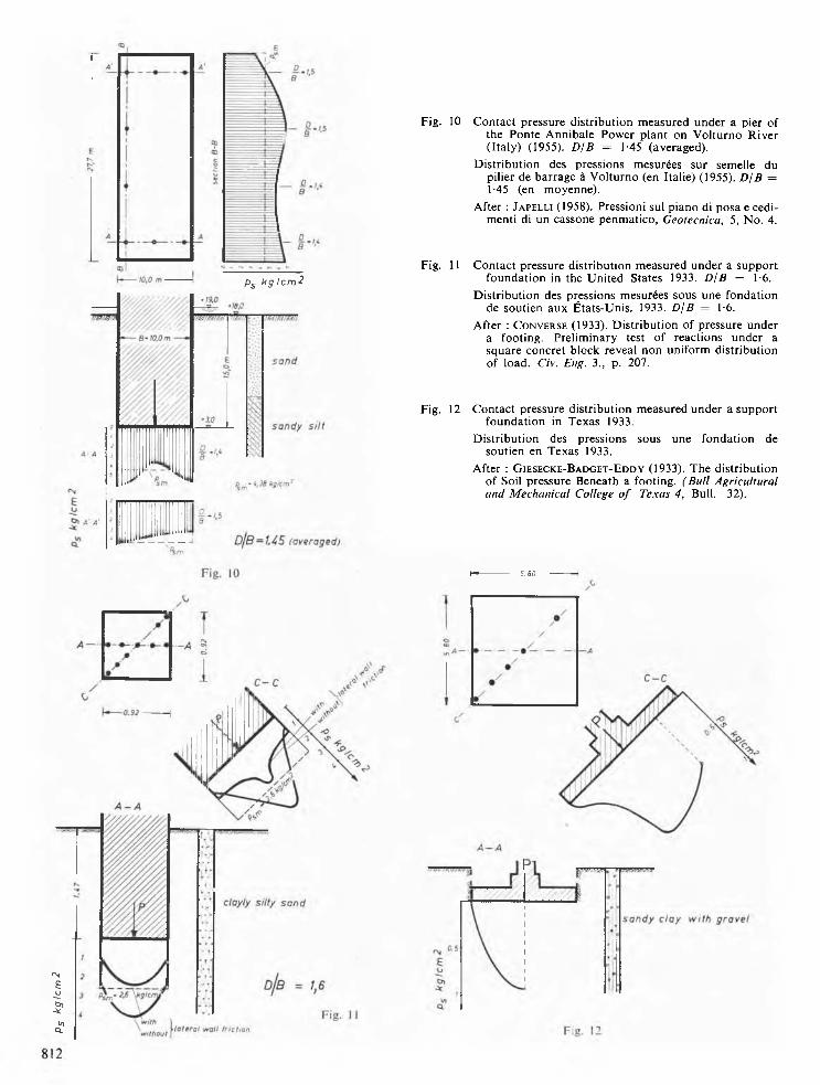
Fig. 10 Contact pressure distribution measured under a pier of the Ponte Annibale Power plant on Volturno River (Italy) (1955). D/B = 1 -45 (averaged).
D istribution des pressions mesurées sur semelle du pilier de barrage à Volturno (en Italie) (1955). DIB =1 -45 (en moyenne).
After : J a p e l l i (1958). Pressioni sul piano di posa e cedimenti di un cassone penmatico, Geotecnica, 5, No. 4.
Fig. 11 Contact pressure distribution measured under a support foundation in the United States 1933. D/B = 1-6.
D istribution des pressions mesurées sous une fondation de soutien aux États-Unis. 1933. DIB = 1-6.
After : C o n v e r s e (1933). D istribution of pressure under a footing. Preliminary test of reactions under a square concret block reveal non uniform distribution of load. Civ. Eng. 3., p. 207.
Fig. 12 Contact pressure distribution measured under a support foundation in Texas 1933.
Distribution des pressions sous une fondation de soutien en Texas 1933.
After : G i e s e c k e -B a d g e t - E d d y (1933). The distribution of Soil pressure Beneath a footing. (Bull Agricultural and Mechanical College o f Texas 4, B u ll. 32).
h »- - - - - - - - 5. 80
Caissons are particu larly suitable fo r the installation o f pressure gauges.
M easurem ents beneath the foundations o f buildings m ust be accepted w ith great cau tion , because the in stalla tion of pressure gauges is generally very difficult. In draw ing graphs o f results, the au thors has rejected several m easurem ents.
2.1. M ainly concave parabolic distribution— O ut o f eleven case records eight show an accum ulation of pressure a t the edges (Figs. 3-10). M ost o f these foundations rest on sand a t a great depth , bu t results a re also available o f a struc tu re on boulder clay (Fig. 8) w here a concave p a ra bo la was also m easured. The concrete block having a d iam eter o f 11-3 m was set up solely for the purpose o f test loading and was provided w ith adequate m easuring instrum ents. In o rder to elim inate la tera l friction, the structure was su rroun ded by a well, w hich rem oved the la teral earth pressure. The m easured d istribu tion o f pressure agrees closely w ith th a t indicated by theroy.
2.2. Full parabolic distribution—There are, how ever, o ther observations m ade o n finished structures w hich show
a fu ll parabolic d istribu tion o f pressure. T hey all apply to clay soils (Figs. 11-13).
T he au th o r considers th a t these a re the only published cases in which pressure d istribu tion is fully parabolic. M oreover, these cases depend on earlier m easurem ents m ade a t a tim e when very little experience o f pressure gauges was available. T hus, w ith the exception o f (Fig. 8) there is a dearth o f reliable observations on cohesive soils. In view o f the divergence in the m easurem ents w ith Berlin boulder clay (Fig. 8) it w ould be prem atu re if, w ithout fu rther aid, we were to seek an exp lanation fo r these variations. It is possible however th a t w ith soft clays m ust assum e a predom inantly plastic flow even w ith allow ance for a generous factor o f safety. T h a t w ould m ean th a t the ground creeps beneath the structure , w hich is generally th e case w ith clay. On the o ther hand, w ith very firm boulder clay a m uch brittle failure is likely to occur.
T herefore, one reaches the conclusion th a t the assum ption on w hich the determ ination o f the con tac t pressure d istribution in the elastic-plastic sta te is based, is in close agreem ent w ith practical experience.
B - B
kglcm^
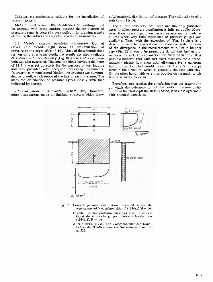
Fig. 13 Contact pressure distribution measured under the west-caisson of Niederfinowship-lift (1934).D/B = 1-6.
D istribution des pressions mesurées sous le caisson Ouest du monte-charge pour bateaux Niederfinow (1934). DIB = 1-6.
After : D e t i g (1934). Die Zwischenpfeiler der K analbrücke des Schiffshebewerkes Niederfinow. Baut. 12, p. 522.
813