
Internal Integrity Management of Rigid Flowlines
70
MainTech AS Org.no: 942 335 229 Granåsvegen 15A, N-7069 Trondheim, Norway Phone: +47 73 95 67 50 / [email protected] Internal Integrity Management of Rigid Flowlines Revision Date Reason for Issue Prepared by: Verified by: Approved by: 3 21.01.22 Issue for Use Jan Erik Salomonsen Øystein Sævik Håvard Wilson Jorunn S. Mæland Stein Valen Grethe Selboe 2 14.01.22 Issue for Use Jan Erik Salomonsen Øystein Sævik Håvard Wilson Jorunn S. Mæland Stein Valen Grethe Selboe 1 06.12.21 Issue for Review Jan Erik Salomonsen Øystein Sævik Håvard Wilson Jorunn S. Mæland Stein Valen Grethe Selboe Project number: P1922 Document number: 00404
-
Upload
khangminh22 -
Category
Documents
-
view
1 -
download
0
Transcript of Internal Integrity Management of Rigid Flowlines

MainTech AS
Org.no: 942 335 229 Granåsvegen 15A, N-7069 Trondheim, Norway
Phone: +47 73 95 67 50 / [email protected]
Internal Integrity Management of Rigid Flowlines
Revision Date Reason for Issue Prepared by: Verified by: Approved by: 3 21.01.22 Issue for Use Jan Erik Salomonsen
Øystein Sævik Håvard Wilson Jorunn S. Mæland
Stein Valen Grethe Selboe
2 14.01.22 Issue for Use Jan Erik Salomonsen Øystein Sævik Håvard Wilson Jorunn S. Mæland
Stein Valen Grethe Selboe
1 06.12.21 Issue for Review Jan Erik Salomonsen Øystein Sævik Håvard Wilson Jorunn S. Mæland
Stein Valen Grethe Selboe
Project number: P1922 Document number: 00404

Title: Internal Integrity Management of Rigid Flowlines Revision: 3 Doc. No.: 00404 Date: 21.01.2022 ____________________________________________________________________________________________________
Page 2 of 69
TABLE OF CONTENTS
1 EXECUTIVE SUMMARY .................................................................................................................... 4
2 INTRODUCTION / BACKGROUND ................................................................................................... 5
2.1 Scope of document .................................................................................................................... 5
2.2 Definition: Rigid flowline ............................................................................................................. 5
2.3 Abbreviations.............................................................................................................................. 6 3 RELEVANT STANDARDS FOR INTERNAL INTEGRITY OF RIGID FLOWLINES .......................... 8
4 ADVANCES IN INTERNAL INTEGRITY MANAGEMENT OF RIGID FLOWLINES OVER THE LAST 30 YEARS ................................................................................................................................ 9
4.1 Introduction ................................................................................................................................. 9
4.2 The first petroleum law of 1985 .................................................................................................. 9
4.3 The Piper Alpha disaster .......................................................................................................... 10 4.4 North Sea Offshore Authorities Forum ..................................................................................... 11
4.5 Norsk Sokkels Konkurranseposisjon (NORSOK) .................................................................... 11
4.6 Samarbeid for sikkerhet ........................................................................................................... 11
4.7 Advances in standards and recommended practices .............................................................. 14 4.7.1 Pipeline design ............................................................................................................. 14 4.7.2 Pipeline remaining strength of corroded pipelines - Defect sizing ............................... 14 4.7.3 Integrity management .................................................................................................. 14
4.8 Advances in prediction models ................................................................................................ 14
4.9 Advances in materials selection for rigid flowlines ................................................................... 14
4.10 Technical advances in monitoring equipment and software .................................................... 16
4.11 Data driven corrosion management and integrated operations ............................................... 17
5 INTERNAL INTEGRITY EVALUATIONS ......................................................................................... 18 5.1 Material selection for rigid flowlines ......................................................................................... 18
5.2 Internal threats for rigid flowlines ............................................................................................. 18 5.2.1 CO2 corrosion .............................................................................................................. 20 5.2.2 General H2S corrosion ................................................................................................. 20 5.2.3 Injected acid corrosion ................................................................................................. 20 5.2.4 Top of line corrosion .................................................................................................... 21 5.2.5 Under deposits corrosion ............................................................................................. 21 5.2.6 Microbiologically induced corrosion ............................................................................. 21 5.2.7 Erosion-corrosion ......................................................................................................... 22 5.2.8 Galvanic corrosion ....................................................................................................... 22 5.2.9 Preferential weld corrosion .......................................................................................... 22 5.2.10 Elemental sulphur ........................................................................................................ 22 5.2.11 Carry-over of glycol ...................................................................................................... 23 5.2.12 O2 corrosion ................................................................................................................. 23 5.2.13 Cracking mechanisms ................................................................................................. 23 5.2.14 Liquid metal embrittlement and amalgamation ............................................................ 24 5.2.15 Internal erosion ............................................................................................................ 24
5.3 Monitoring equipment ............................................................................................................... 25 5.3.1 Multiphase flowmeters ................................................................................................. 25 5.3.2 Erosion monitoring ....................................................................................................... 25 5.3.3 Sand monitoring ........................................................................................................... 25 5.3.4 Sensors ........................................................................................................................ 25

Title: Internal Integrity Management of Rigid Flowlines Revision: 3 Doc. No.: 00404 Date: 21.01.2022 ____________________________________________________________________________________________________
Page 3 of 69
5.3.5 Corrosion and erosion probes and coupons ................................................................ 25
5.4 Corrosion models - Prediction of corrosion rates ..................................................................... 27
5.5 Predictive techniques applied for flowline asset integrity management................................... 29 5.5.1 General ........................................................................................................................ 29 5.5.2 Prediction and analysis - Integrity operation window................................................... 29 5.5.3 Machine Learning applied for flowline asset integrity management ............................ 30 5.5.4 Seven steps to deploy machine learning in flowline asset integrity management ...... 31
5.6 Inspection methods for internal integrity .................................................................................. 36 5.6.1 General ........................................................................................................................ 36 5.6.2 MFL – Magnetic flux leakage ....................................................................................... 37 5.6.3 UT – Ultrasound technology ........................................................................................ 37 5.6.4 ART – Acoustic resonance technology ........................................................................ 38 5.6.5 EC – Eddy current........................................................................................................ 38 5.6.6 EMAT - Electromagnetic acoustic transducer ............................................................. 38 5.6.7 Combined ILI tools ....................................................................................................... 39 5.6.8 External inspection of internal integrity ........................................................................ 39 5.6.9 Spool/equipment retrieval ............................................................................................ 39 5.6.10 Selection of inspection method for internal defects in flowlines .................................. 39
5.7 Workflow for integrity management ......................................................................................... 41 5.7.1 Regulatory requirements ............................................................................................. 41 5.7.2 Risk Assessment and IM Planning .............................................................................. 43 5.7.3 Inspection, Monitoring & Testing ................................................................................. 49 5.7.4 Integrity Assessment.................................................................................................... 49 5.7.5 Mitigation Intervention & Repair ................................................................................... 50 5.7.6 Review and update risk assessment and plans .......................................................... 50
6 FUTURE IN FLOWLINE INTEGRITY MANAGEMENT.................................................................... 51
6.1 The unknown unknowns .......................................................................................................... 51 6.2 Turning data into wisdom ......................................................................................................... 53
6.3 Collective mindfulness ............................................................................................................. 54
6.4 How to meet the future ............................................................................................................. 55
7 REFERENCES ................................................................................................................................. 56
8 APPENDIX ....................................................................................................................................... 58
8.1 Appendix 1 – Relevant standards ............................................................................................ 58 8.2 Appendix 2 - CO2 corrosion models – update from IFE ........................................................... 62
8.3 Appendix 3 – Relevant monitoring parameters ........................................................................ 66

Title: Internal Integrity Management of Rigid Flowlines Revision: 3 Doc. No.: 00404 Date: 21.01.2022 ____________________________________________________________________________________________________
Page 4 of 69
1 EXECUTIVE SUMMARY The Petroleum Safety authority (PSA) commissioned MainTech AS to establish the status on integrity management for rigid flowlines in the Norwegian oil and gas operations. This document aims to constitute a high-level reference for understanding the present practices and requirement related to integrity management. Further the report aims to be “thought provocative” in discussing what are the success factors for ensuring future continuous improvement in rigid flowline integrity management. The work is based on MainTech internal knowledge, publicly available information, and specifically prepared studies. The report summarises the most important relevant standards that affects integrity management of rigid flowlines (Section 3). Further the report summarises the positive development in integrity management during the last 30 years of operation on the Norwegian sector, including advances in; governance, cooperation, standards, management processes, materials, condition monitoring- methods and equipment (Section 4). Relevant threats and their mechanisms are discussed as well as available methods and equipment for monitoring relevant parameters. An overview of available corrosion prediction models is also presented. Relevant combined predictive techniques applied for flowline integrity management is discussed, including data driven models e.g., Machine Learning. Different risk-based integrity management approaches are discussed (Section 5). Our thoughts on the future development in risk management of rigid flowlines are discussed, where we emphasise the importance and challenges of closing the double circuit PDCA improvement loop. Further, how to gain more wisdom to ensure continuous improvement of integrity management in the future is discussed as a concluding chapter (Section 6). The development in integrity management of rigid flowlines at the Norwegian shelf has shown a positive trend throughout the last 30 years, with a resulting very few incidents and leakages. Much of this positive development must be credited to the change in governance as introduced with the new petroleum act in 1985. Advances has been made in integrity management work processes, standardisation, corrosion models, materials, and monitoring. Challenges and failures have however been experienced related to the introduction of novel technology, where failure mechanisms have not been fully understood prior to application. As the oil and gas industry has matured, knowledge has indeed been shared. Sharing in the form of collaboration, research reports, investigation reports, standards and recommended practices, has contributed to the overall reduction of risk in the industry. The report presents references to relevant standards and recommended practices. Key to integrity management of rigid flowlines is to apply subject matter expertise for the understanding of threats in the context of risk. The report presents a detailed overview of the threats encountered related to materials degradation. The report also presents an overview made by IFE of the status of available corrosion prediction models and where they can be procured. Risk based inspection and verification approaches are applied to focus on identifying, estimating, and quantifying the important threats in flowline management. This report thus presents different ways of applying; predictive methods, inspection methods, and continuously improving workflows for integrity management Future integrity management for flowlines is expected to be more data driven as increased interconnectivity allows for more sensor applications and time-series data to be harvested. Novel methods as machine learning have the potential to enable an automated analysis of sensor data. It is the authors strong belief that this data driven development has the potential to increase the pace of knowledge extraction and give valuable decision support in future flowline integrity management. In parallel with implementing new data driven methods it is the authors recommendations to the industry to continue the established improvement loops, perform more research and maintain international arenas for collaboration, standardisation, and sharing knowledge.

Title: Internal Integrity Management of Rigid Flowlines Revision: 3 Doc. No.: 00404 Date: 21.01.2022 ____________________________________________________________________________________________________
Page 5 of 69
2 INTRODUCTION / BACKGROUND
2.1 Scope of document MainTech AS was commissioned by the Petroleum Safety Authority Norway (PSA) to establish a guideline for internal integrity management for infield rigid flowlines to prevent hydrocarbon leakages. Authors MainTech AS:
- Jorunn Snøan Mæland, M.Sc. - Håvard Wilson, Ph.D. - Øystein Sævik, Ph.D. - Jan Erik Salomonsen, M.Sc.
2.2 Definition: Rigid flowline A seamless or welded pipeline, single or bundled, including connectors, under internal pressure, made from metallic materials transporting unprocessed production fluids from wellhead facilities to tie-ins or risers to process facilities.
Figure 2-1. Rigid flowlines (Subsea 7).

Title: Internal Integrity Management of Rigid Flowlines Revision: 3 Doc. No.: 00404 Date: 21.01.2022 ____________________________________________________________________________________________________
Page 6 of 69
2.3 Abbreviations AC Alternating Current AI Artificial Intelligence AISI American Iron and Steel Institute ALARP As Low As Reasonable Practical (safety philosophy principle) AMS Asset Management System API American Petroleum Institute ASME American Society of Mechanical Engineers ART Acoustic Resonance Technology (Ultrasonic exited standing waves) ASTM American Society of Testing Materials BFDW Before Dewatering BuBi Butting Bimetal (Clad pipe) COABIS Component Oriented Anomaly Based Inspection System CEN Comité Européen de Normalisation (European Standardisation Committee) CMMS Computerised Maintenance Management System CoF Consequence of Failure CR Corrosion Rate CRA Corrosion Resistant Alloys CS Carbon Steel CT Computer Tomography CVI Close Visual Inspection DFI Dossier For Installation DIKW Data, Information, Knowledge and Wisdom DNV Det Norske Veritas DSHA Defined Situations of Hazards and Accident DSS Duplex Stainless Steel (22Cr) ECN Electrochemical Noise EC Eddie Current ECT Eddie Current Technology EMAT Electro Magnetic Acoustic Transducer (electromagnetic exited sound waves) ER Electrical Resistance ERP Enterprise Resource Planning ESDV Emergency Shut Down Valve FMEA Failure Mode and Effect Analysis FSM Field Signature Method GVI General Visual Inspection HAZ Heat Affected Zone HAZOP Hazard and Operability Analysis (method) HAZID Hazard Identification (method) HCR Hydrocarbon Releases HIC Hydrogen Induced Cracking HISC Hydrogen Induced Stress Cracking (external) HSE Health and Safety Executive IFE Institute For Energy Technology IIoT Industrial Internet of Things ILI In-Line Inspection (intelligent pigging) ID Internal Diameter IM Integrity Management IO Integrated Operations IoT Internet of Things IOW Integrity Operating Window ISO International Standardisation Organisation IWP Integrity Work Plan JIP Joint Industry Project LPR Linear Polarisation Resistance MAOP Maximum Allowable Operating Pressure MFL Magnetic Flux Leakage

Title: Internal Integrity Management of Rigid Flowlines Revision: 3 Doc. No.: 00404 Date: 21.01.2022 ____________________________________________________________________________________________________
Page 7 of 69
MIC Microbiological Induced Corrosion ML Machine Learning MPM Multiphase Meters NACE National Association of Corrosion Engineers NCS Norwegian Continental Shelf NDE Non-Destructive Examination NORSOK The Norwegian shelf competitive position NPD Norwegian Petroleum Directorate NSOAF North Sea Authorities Forum OCTG Oil Country Tubular Goods OD Outer Diameter PARLOC Pipeline and Riser Loss of Containment PAUT Phased Array Ultrasonic Testing PDCA Plan Do Check Act (improvement circle process) PE Pulsed Echo shear wave technology (ultrasonic technique) PSA Petroleum Safety Authority Norway (Petroleumstilsynet) PoD Probability of Detection PoF Probability of Failure PT Present Time RBI Risk Based Inspection RCM Reliability Centred Maintenance RNNP Risiko Nivå I Norsk Petroleum (Risk database) ROV Remotely Operated Vehicle RP Recommended Practice SCC Stress Corrosion Cracking SDSS Super Duplex Stainless Steel (25Cr) SMSS Super Martensitic Stainless Steel (13Cr) SS Stainless Steel SSC Sulfide Stress Cracking TFM Total Focusing Method (ultrasonic array technique) TOFD Time of Flight Diffraction (Ultrasonic technique) TOL Top Of Line TSA Thermally Sprayed Aluminium (external coating) UT Ultrasound Technology WOAD World Offshore Accident Database

Title: Internal Integrity Management of Rigid Flowlines Revision: 3 Doc. No.: 00404 Date: 21.01.2022 ____________________________________________________________________________________________________
Page 8 of 69
3 RELEVANT STANDARDS FOR INTERNAL INTEGRITY OF RIGID FLOWLINES NORSOK, International Organization for Standardization (ISO), Det Norske Veritas (DNV), American Society for Testing and Materials (ASTM) and American Petroleum Institute (API) have developed standards and recommended practices to ensure the integrity of pipelines, from design to operation. The most important standards and recommended practices to manage internal threats are listed in Table 3-1, while other relevant standards can be found in chapter 8.1. Table 3-1 Key standards for managing internal threats for production pipelines on NCS.
Standard ID Rev. Name Year Description NORSOK M-001 5 Materials
selection 2014
Provides guidance for: material selection, corrosion protection and corrosion control, design limitations for specific materials and qualification requirements for new materials or new applications.
NORSOK Z-008 4 Risk based maintenance and consequence classification
2017 Provides guidelines for maintenance management of technical barrier elements
NORSOK M-506 3 CO2 corrosion rate calculation model
2017 Provides a recommended practice for calculation of corrosion rates in hydrocarbon production and process systems where the corrosive agent is CO2
DNV-RP-F116 Integrity Management of Submarine Pipeline Systems
2019 Provides guidance on how to establish an Integrity Management System, including: threat identification, risk assessment, planning, inspection, monitoring, testing, integrity assessment, mitigation, intervention, and repair.
DNVGL-ST-F101 (Previously OS-F101)
Submarine Pipeline Design
2017
Provides recommendations on concept development, design, construction, operation and abandonment of Submarine Pipeline Systems
Title: Internal Integrity Management of Rigid Flowlines Revision: 3 Doc. No.: 00404 Date: 21.01.2022 ____________________________________________________________________________________________________
Page 9 of 69
4 ADVANCES IN INTERNAL INTEGRITY MANAGEMENT OF RIGID FLOWLINES OVER THE LAST 30 YEARS
4.1 Introduction The development of integrity management of rigid subsea pipelines on the Norwegian shelf from 1990 and on, was strongly influenced by the turning point in governance by the new petroleum act and law of internal control of 1985. This new regime together with important events gave a strong focus to integrity management: - The Piper Alpha disaster in the UK sector - North Sea Offshore Authorities Forum (NSOAF) - cooperation for safety - The Norwegian introduction of the NORSOK standards and tripartite cooperation between
operators, government, and work organisations. - Technical and managerial advances
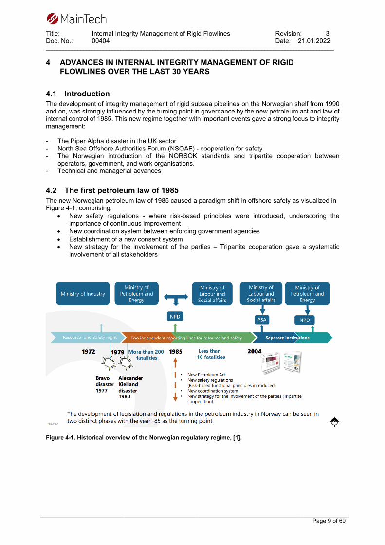
4.2 The first petroleum law of 1985 The new Norwegian petroleum law of 1985 caused a paradigm shift in offshore safety as visualized in Figure 4-1, comprising:
• New safety regulations - where risk-based principles were introduced, underscoring the importance of continuous improvement
• New coordination system between enforcing government agencies • Establishment of a new consent system • New strategy for the involvement of the parties – Tripartite cooperation gave a systematic
involvement of all stakeholders
Figure 4-1. Historical overview of the Norwegian regulatory regime, [1].

Title: Internal Integrity Management of Rigid Flowlines Revision: 3 Doc. No.: 00404 Date: 21.01.2022 ____________________________________________________________________________________________________
Page 10 of 69
4.3 The Piper Alpha disaster On July 6th. 1988, the Piper Alpha North Sea oil platform suffered a massive leakage of gas condensate, killing 167 people, only 62 survived. This disaster initiated a change in asset integrity management in the UK oil and gas industry. The final report (Lord Cullen report) was published in November 1990, [2]. The report included 106 directions, which were all accepted by the industry. As a result of the report, the Offshore Installations Safety Case Regulations came into force in 1992 by the UK Offshore safety act. By the following year, a safety case for every installation had been submitted to the HSE. By November 1995, each of these had been accepted by the HSE. In 2000, the British government unveiled a 10-year strategy for improving safety in the oil and gas industry. This included targets for the sector such as a 10 percent reduction in the rate of fatalities and major injuries. Magne Ognedal at PSA was a key witness in the Lord Cullen investigation where he explained the new Norwegian model of governance and internal control of 1990, replacing the regulations of 1981. Changing from fixed quantitative requirements to guidelines where the operator is required to take an active role in defining and establish criteria. The new British safety standards that arose from the Cullen report was strongly influenced by the new Norwegian model. A fundamental principle of the Norwegian safety regime is that since the operator controls his business, the operator therefore should control the safety aspect of his operations. This principle of internal control was formally given in 28th of June 1985 for the petroleum activities, and later became the law of safety management in all industries in Norway in 1996. A rationale to this change in legislation is given by Magne Ognedal as a comment to the Lord Cullen report.
“Safety cannot be inspected into a platform” – In Norway it has had a tendency to create a situation where people do what they are told by these inspections and then wait more or less for the next inspection to come along and tell them what to do then. “We found that where we had identified a number of things on a platform requiring attention, and had notified the operator of these, the operator would tend to react only on the matters drawn to this attention. We asked operators whether they were evaluating our comments on individual platforms across their platforms and fields and examining their systems in the light of the specific matters we were drawing to their attention. It appeared from the responses we received that this was not being done. We considered how we could focus on these issues with a view to motivating companies to do this themselves”.
Quote; Magne Ognedal at the Cullen investigation Ch.21, [2]. The legislative recommendations arising from the Cullen report, affected a change in flowline integrity management:
A safety case prepared by the operator for all installations where the potential major hazards of the installation and risk to personnel thereon have been identified, and appropriate controls provided. Drawn on quality assurance principles e.g., ISO 9000 (continuous improvement). A demonstration as far as reasonably practical that identified hazards has been minimised. The update of the safety case every 3 years, maximum 5.

Title: Internal Integrity Management of Rigid Flowlines Revision: 3 Doc. No.: 00404 Date: 21.01.2022 ____________________________________________________________________________________________________
Page 11 of 69
4.4 North Sea Offshore Authorities Forum North Sea Offshore Authorities Forum (NSOAF) was established in 1989 and comprises all nations with oil and gas operations in the North Sea. The organisation was established to ensure a continuous improvement of health environment and safety in the North Sea operations. The new directions in the UK shelf thus implicated learnings to the other nations in the cooperation. In Norway a gas leakage reduction initiative was started (OLF “GaLeRe project”) with the aim to reduce hydrocarbon leakages by 50% to less than 20 per year within 2005. This aim was met by 18 leakages in 2005 and the project was continued with new 50% targets for 2008, this target was met in 2007, [3].
4.5 Norsk Sokkels Konkurranseposisjon (NORSOK) In 1993 the government initiated a project called Norsk Sokkels Konkurranseposisjon (the Norwegian shelf competitive position) with the aim to reduce field development costs on the Norwegian shelf. This project led to the NORSOK standardisation work that presented common standards for the oil and gas industry. The standards have been developed on basis of best practices to ensure adequate safety, value adding and cost effectiveness for petroleum industry developments and operations. Furthermore, NORSOK standards are as far as possible intended to replace individual oil company specifications and serve as references in the authorities’ regulations. The standards are based on 40 years of experience from the industry. The initiative has been a success and NORSOK standards have been adapted by other nations regulations. Currently there are 79 active standards within NORSOK. The NORSOK standards forms basis for standardised materials selections, valve configurations, gaskets etc. and hence, support a more unified integrity management across companies operating on the Norwegian continental shelf.
4.6 Samarbeid for sikkerhet Primo year 2001 a cooperation was established in Norway called “Samarbeid for Sikkerhet” (cooperation for safety), a voluntary tripartite cooperation with participants from employers' organisations, employee unions and the government. Participants from the industry are experts from the operators, suppliers, service companies, the Petroleum Safety Authority and the maritime industry, and the sharing of experience and expertise leads to best practice in the form of standards. The Sector Board Petroleum Industry ensures overall standardization in the industry through coordination of international standardization work in ISO and CEN and the industry standardization work of NORSOK. Defined Situations of Hazard and Accident (DSHAs) are a key part of the data that is entered in the PSA database to control and visualise the Risk Level in Norwegian Petroleum Activities (RNNP). Figure 4-2 presents the number of incidents without normalisation against exposure data (working hours).

Title: Internal Integrity Management of Rigid Flowlines Revision: 3 Doc. No.: 00404 Date: 21.01.2022 ____________________________________________________________________________________________________
Page 12 of 69
Figure 4-2. Development in defined hazard and accident conditions with a potential for causing major accidents, [4] * within the safety zone The general number of leakages in the industry has steadily been reduced from a maximum of 43 in year 2000 to 5 in 2020, [4]. The weighed major accident potential has similarly been reduced in accordance with Figure 4-3.
Figure 4-3. Risk exposure from leakages weighed from risk potential [4]. As can be seen from the Figure 4-2 and Figure 4-3, there is a clear trend of continuous improvement in risk reduction from leakages on the Norwegian petroleum activities. It should be noted that the number of installations has increased in the period, showing a double positive effect, and indicating that the integrity efforts are indeed working.

Title: Internal Integrity Management of Rigid Flowlines Revision: 3 Doc. No.: 00404 Date: 21.01.2022 ____________________________________________________________________________________________________
Page 13 of 69
Figure 4-4. DSHA-9 leakages in subsea installations flowlines and risers within safety zone - extract from RNNP, [4]. Figure 4-4 shows that there are very few incidents comprising DSHA-9, leakages in subsea installations, flowlines and risers relevant for this report. The number of leaks has been reduced to a level of no leaks the last three years. One of the major leaks on the Norwegian shelf outside the safety zone was the Shell Draugen Garn West flowline rupture in 2003. The failure mechanism was externally initiated HISC on a 25Cr duplex hub. Further overview of subsea leakages and incidents in the period is given in table 3.1. of reference [5].

Title: Internal Integrity Management of Rigid Flowlines Revision: 3 Doc. No.: 00404 Date: 21.01.2022 ____________________________________________________________________________________________________
Page 14 of 69
4.7 Advances in standards and recommended practices In the last 30 years, the following standards, and their development, have affected the integrity management of rigid flowlines:
4.7.1 Pipeline design − DNV OS F101 Submarine Pipeline systems (1. Ed. 1996 Introducing LRF Design) − ASME B31.4 Liquids pipelines (non-compressible) − ASME B31.8 Gas and distribution pipelines (compressible fluids = more stringent stress
analysis)
4.7.2 Pipeline remaining strength of corroded pipelines - Defect sizing − ASME/ANSI B31G Criterion (Battelle 1984) − Shell-92 (Failure Pressure of corroded pipeline – 1992) − RSTRENG (Modified - less conservative B31G criterion computer based- 1996) − DNV RP-F101 Corroded pipelines (1. Ed. 1999)
4.7.3 Integrity management − API 580 Risk Based Inspection (1. Ed. 2002) − API RP 581 Risk Based Inspection Technology (1. Ed. 2000) − DNV RP F116 Integrity Management Submarine Pipeline (1. Ed. 2009)
4.8 Advances in prediction models See chapters 5.4 and 5.5.
4.9 Advances in materials selection for rigid flowlines The workhorse of flowlines in the Norwegian sector is OCTG carbon steel, seamless linepipe according to API 5A, grades; X52, X60 and X65 with or without modifications for weldability. In 1988, 22Cr duplex (DSS) was introduced at the Norwegian shelf for the Tommeliten-Edda field, ten years after the first installation by NAM for the NL Groningen field. DSS gained more interest throughout the 1990ties for a number of field developments. 25Cr Duplex (SDSS) was also employed for a few flowlines, but the application was not without problems as HISC caused rupture both at the UK Foinaven field in 1996, and at the Norwegian Draugen Garn West field in 2003. As a result of investigations and laboratory testing, a recommended practice was issued by DNV in 2008, [6]. The quest for cost reductions and efficient reeling installation inspired the development of weldable low carbon 13Cr super martensitic stainless steels with more than 2% Molybdenum (13Cr SMSS) for flowline applications. Statoil carried out a test programs in 1995 to 1997 which resulted in a use of 13Cr SMSS, first at the Gullfaks satellite developments that started operation late 1998. The following year, the material was applied for flowlines at the Statoil Åsgard field. The 13Cr SMSS flowlines installed at the Åsgard field suffered from internal pitting corrosion due to accidental filling with seawater during installation, [7]. Prior to start-up at Statoil’s Åsgard field early in 2002, leaks were detected during pressure testing in two of the 13Cr SMSS flowlines. The leaks were caused by circumferential cracking close to 316L anode pads welded onto the pipelines. The pads serve as connectors for the cathodic protection system. The cracks were located at the SDSS fillet weld toe and initiated in the 13Cr SMSS heat affected zone (HAZ). The initiation mechanism was assumed to be Hydrogen Induced Stress Cracking (HISC) which was attributed to hydrogen charging from the cathodic protection system (i.e., the sacrificial anodes) due to sea water entrance and crevices in the field joint coating adjacent to the anode attachments. Further

Title: Internal Integrity Management of Rigid Flowlines Revision: 3 Doc. No.: 00404 Date: 21.01.2022 ____________________________________________________________________________________________________
Page 15 of 69
crack growth and propagation into the base metal pipe wall is associated with fatigue loading by vibrational pipe bending [8], [9]. One of the pipelines were re-inspected by a tethered ILI ultrasonic Pulse echo & TOFD crack detection tool in September 2014 and 10 crack like indications were detected by PE related to the 176 anode pads of the pipeline. The indications were further analysed and sized by the TOFD technique. 7 of the 10 were verified as crack like features, where the deepest were sized with a depth of 2,6mm and a length of 15mm. The remaining 3 identified by PE were assumed to be below the threshold of 1mm for the TOFD method. In 2001, 13Cr SMSS was introduced for the Hydro Tune project, this application was not a success as the pipelines already in the commissioning phase suffered from hydrogen induced leakages that originated from welding and cathodic protection (external HISC), [10]. The flowlines were never put in production and were replaced by carbon steel the following year, 2002. Statoil (that merged with Hydro in 2007) pursued to gain control of the HISC failure mode as well as welding issues, and later years, 13Cr SMSS was installed with success for several field developments. The 13Cr SMSS limits to applications of up to 140°C relates to SCC in H2S environments. The development in SMSS tends towards 17Cr compositions that approach an operating temperature up to 200°C. Current alternatives are DSS or clad. Metallurgically bonded clad pipes consisting of a load carrying outer pipe with a thin inner layer of stainless steel, have always been an option for flowlines. However, high fabrication costs and restrictions in materials combinations, related to heat-treatment, have restricted the use. In the 1990ties the company Butting GmbH developed a cost efficient mechanically bonded clad pipe called BuBi (Butting Bimetal), allowing for several materials combinations, based on a seam welded outer pipe. This solution gained interest since the 2000s to PT e.g., the installation at the present Aasta Hansteen project. In the application of stainless and clad solutions, corrosion management had to change to include other relevant failure modes than for carbon steel. E.g., pre-operations water management/ deoxidization in the installation process before commissioning has a much higher focus in stainless steel and clad flowlines to prevent pitting corrosion.

Title: Internal Integrity Management of Rigid Flowlines Revision: 3 Doc. No.: 00404 Date: 21.01.2022 ____________________________________________________________________________________________________
Page 16 of 69
4.10 Technical advances in monitoring equipment and software The development of integrity management in the last 30 years is strongly related to the field developments in the period, the emerging new NORSOK standards and novel technical developments in inspection tools, software, management, and monitoring solutions e.g.:
- Development of inline inspection tools o Transverse MFL, Eddy current, Ultrasonic, shear wave, EMAT, ART, PAUT, TFM,
Laser + - Development of point monitoring tools
o Field signature method (FSM), Subsea high sensitivity ER probes, clamp on ultrasonics, Ultrasonic array mats, Ultramonit SEC +
- Development of microprocessor loggers o MultiCorr CorrOcean 1989
- Development of ROV carried inspection tools, see section 5.6.8. - Development of analytic multiphase flowmeters - Development in Flow assurance simulation
o LedaFlow, OLGA/PIPESIM, SYNERGI o HYSYS
- Development in corrosion models o See chapter 5.4.
- Development of sand and/or erosion monitoring system o ER principle, ultrasonic principle
- Development of asset integrity management software o SYNERGI, BiCycle, IMS PLSS (Hydrocor integrated) +
- Development of standardised solutions o NORSOK +
- Time series databases and visualisation o ABB System o PI System
- Development and introduction of new materials for flowlilnes o 22Cr duplex, 13Cr martensitic, clad, mechanically lined pipes BuBi
Field signature method FSM is a trademark for Emerson LedaFlow is a trademark for Kongsberg Digital OLGA/PIPESIM are trademarks for Schlumberger HYSYS is a trademark of Aspentech SYNERGI is a trademark for Det norske Veritas ClampOn is a trademark for ClampOn AS BiCycle is a trademark of BiCycle BV PI System is a trademark of AVEVA OSIsoft IMS PLSS is a trademark of Cenosco UltraMonit SEC is a trademark of Sensorlink
As an example: The development of subsea Field Signature Monitoring (FSM) non-intrusive point monitoring tool by the Norwegian company CorrOcean in the 1990-ties, was supported with a corrosion estimation model, combined with a pH model and OLGA multiphase wet gas flow simulation water wetting model, where uncertainties in the input parameters were handled by Montecarlo simulation. The models were employed together to define the optimum point in a pipeline where the point monitoring tool should be placed to give representative corrosion rate measurements [11]. This calculation tool is further developed by Force Technology with the current trade name CorPos-ADTM. The FSM solution for monitoring was selected as basis for asset integrity monitoring for several field developments on the Norwegian shelf. Sadly, some of the installations failed, leaving the operator with no possibility for indirect verification. Throughout the 1990-ies, corrosion and erosion monitoring equipment were developed and deployed in flowlines. However, these installations were often made by the instrument discipline and presented locally to the operators of field control rooms. In many instances the data from these sensors stopped

Title: Internal Integrity Management of Rigid Flowlines Revision: 3 Doc. No.: 00404 Date: 21.01.2022 ____________________________________________________________________________________________________
Page 17 of 69
there, thus not included in an overall inspection and analytic corrosion management work process. The maturity of implementing corrosion management processes however increased throughout the late 2000 years. An initiative from SINTEF called Smart pipe with support from several service providers and oil companies were launched in 2006. The project idea is to install distributed sensors along the flowline to provide a self-monitoring pipeline. Only a pilot demonstrator installation has been made. At the present, the trend is to apply non-intrusive point monitoring equipment subsea and intrusive equipment topside, see section 5.3 and 5.6.
4.11 Data driven corrosion management and integrated operations Throughout year 2000 and on, advances were made in data connectivity, fibreoptic cables, transport protocols, wireless sensors, analytics, and visualisation. Time series sensor data that previously had only been available at the facility control room were made available for the corrosion engineers, and it was possible to define integrity dashboards with defined integrity operating windows related to internal corrosion and other failure modes and deterioration mechanisms. The idea of integrated operations where experts from various disciplines could view and analyse data at centralised operations centres emerged from the mid-2000 and IO rooms were established at several operators where operations could be monitored and analysed in detail by onshore domain experts. This data driven trend is still emerging and more advanced statistical mathematical and AI simulators will be developed in the years to come. One example in the present application of simulation/digital twin used for simulation of water removal from flowlines is the company Billington Process Technology AS (BPT) that utilises OLGA and HYSYS together to simulate internal pig runs for water removal. A current problem with IO Centres is that the large number of data, monitoring applications and trends require a lot of manhours to handle. In many cases the operators are not able to close the continuous improvement loop by analysing and acting on all data. Advances are made to automate the evaluations and analysis by use of artificial intelligence and expert systems logic.

Title: Internal Integrity Management of Rigid Flowlines Revision: 3 Doc. No.: 00404 Date: 21.01.2022 ____________________________________________________________________________________________________
Page 18 of 69
5 INTERNAL INTEGRITY EVALUATIONS 5.1 Material selection for rigid flowlines NORSOK M-001 [12] gives recommendations to materials selection and corrosion evaluations for subsea pipelines and flowlines. The latest revision of NORSOK M-001 generally refers to ISO21457 [13], which was written based on NORSOK M-001. Typical materials for flowlines in hydrocarbon production service (well stream) conditions as recommended by NORSOK M-001 and ISO21457 are:
• Carbon steel with or without chemical treatment • Carbon steel, internally cladded/lined with type 316, alloy 825 or alloy 625 • 22Cr duplex stainless steel • 13Cr martensitic stainless steel with low carbon content (13Cr SMSS)
5.2 Internal threats for rigid flowlines A corrosion evaluation should be carried out to determine the general corrosivity of the internal fluids for the materials under consideration. NORSOK M-001 and ISO21457 give recommendations on relevant corrosion mechanisms and the specified process design parameters that should be considered. Parameters considered should be:
• CO2 • H2S • Temperature • Organic acids • Oil/gas properties and water content • Oxygen • Elemental sulphur • Mercury • Production chemicals
The internal threats to the integrity of rigid flowlines are described shortly in this chapter and summarized in Table 5-1. Table 5-1 Adjusted and expanded from [14] Internal threat
Initiator Flow conditions
Relevant materials
Relative corrosion rate2
Morphology Control measures
CS CRA1
CO2-corrosion CO2 + free water
Water wetting X - Medium
General / pitting / mesa
NDE /ILI/ IOW
Top of line corrosion
CO2 + condensed water
Gas phase + Stratified flow
X - High
Localized ILI /IOW/GVI
Preferential weld corrosion
CO2 + free water
Water wetting X - Medium
Localized NDE / ILI / Design
General H2S-corrosion
H2S + free water
Water wetting X X Low
General / pitting /
NDE /ILI/ IOW
Sulfide stress cracking (SSC)
H2S + free water + tensile stress
Water wetting X X Abrupt Crack IOW / Design
Hydrogen induced cracking (e.g., HIC)
H2S + free water
Water wetting X - Abrupt Crack IOW / Design
Microbiologically influenced corrosion (MIC)
Microorganism + free water + organic
Slow or stagnant flow
X X High
Localized ILI / IOW

Title: Internal Integrity Management of Rigid Flowlines Revision: 3 Doc. No.: 00404 Date: 21.01.2022 ____________________________________________________________________________________________________
Page 19 of 69
Internal threat
Initiator Flow conditions
Relevant materials
Relative corrosion rate2
Morphology Control measures
CS CRA1
matter often combined with deposits
Erosion-corrosion
Produced sand + O2/CO2 + free water
High flow velocity
X X High
General / localized /
ILI /IOW
Under deposit corrosion
O2/CO2 + trapped water + debris/ scaling
Slow or stagnant flow
X - Medium
Localized ILI /IOW
Galvanic corrosion
O2/CO2 + different material + free water
Water wetting X - Medium
Localized NDE / ILI / Design
Elemental sulphur
H2S + O2 + free water/ S + free water
Water wetting X High
Pitting ILI /IOW
Carry-over of glycol
H2S +O2 + free water/ CO2 + free water
Low
NDE / ILI / IOW
(Injected) acid corrosion
Acid wetting X X Low / Medium
NDE / ILI / IOW
Liquid metal embrittlement
Liquid metal (Hg)
Metal wetting - - Abrupt Crack IOW
Erosion Produced sand High flow velocities
X X High Localized ILI / IOW
O2-corrosion3 O2 + free water
Water wetting X X Low
General NDE /ILI/ IOW
Stress corrosion cracking3
H2S + Cl/oxidant + free water + tensile stress
Water wetting - X Abrupt Crack IOW
Notes 1CRA includes the corrosion resistance alloys commonly used for subsea flowlines 13Cr (SMSS) SS316L/Alloy 825/Alloy 625 (clad liner) 22Cr Duplex (DSS) 25Cr Super Duplex (SDSS) 2 Relative corrosion rates provide a guideline for the relative corrosion rate that is typical for the corrosion threat, ranking the threats as either Low, Medium, High or Abrupt. Typically, corrosion threats with High have a higher corrosion rate than Medium or Low etc. Abrupt are time independent threats. 3Oxygen is not inherently available in the flowlines transporting fluids directly from the wells, and these threats are therefore unlikely to occur.

Title: Internal Integrity Management of Rigid Flowlines Revision: 3 Doc. No.: 00404 Date: 21.01.2022 ____________________________________________________________________________________________________
Page 20 of 69
5.2.1 CO2 corrosion CO2 corrosion, commonly called sweet corrosion, requires CO2 and free water to occur and is one of the most common internal corrosion threats for flowlines [15]. CO2 dissolves in the water phase and forms a weak carbonic acid (H+ + HCO3-) which is corrosive to carbon and low alloyed steel. CO2 corrosion can reach corrosion rates of several mm per year. The morphology of CO2 corrosion attack varies and can include uniform corrosion or more localized forms like pitting corrosion (not to be confused with localized corrosion on stainless steels) and mesa attack. The reason for the different corrosion morphologies is the formation of iron carbonate on the internal pipe surface which can protect the pipeline from corrosion where formed. If this iron carbonate scale is unable to form, uniform corrosion is expected, but if a scale is formed and damaged locally, corrosion can initiate resulting in e.g., mesa attack. CO2 corrosion rate increases linearly with increasing pressure and CO2 content and with decreasing pH, however the relationship with temperature is more complex. At lower temperatures higher corrosion rates is expected than for intermediate temperatures because the iron carbonate scale formed at low temperature is easily removed by the flow, while a more protective scale can form and reduce the corrosion rate at intermediate temperatures. Organic acids, turbulent flow and oxygen can dissolve or damage the scale and thus greatly increased the corrosion rate. CO2 corrosion models and relevant parameters are described in more detail in chapter 5.4.
5.2.2 General H2S corrosion H2S corrosion, commonly called sour corrosion (not to be confused with sour service, see section 5.2.13.1), requires H2S and free water to occur. H2S similarly to CO2, dissolves in the water phase, forms a weak acid (H+ + HS−) that adds to corrosion of the flowline. Iron sulfide scale can form as a corrosion product and slow the corrosion rate ( [15]. As with CO2 corrosion, the formation of scale causes the corrosion morphology to vary between uniform corrosion and more localized attacks [16]. Due to the formation of protective iron sulfide scale the effect of temperature, H2S partial pressure and pH on the corrosion rate is complex. The corrosion rate can be higher at low and high temperature than at intermediate temperature, while the opposite can be the case for partial pressure H2S with the highest rates at intermediate partial pressure. The presence of H2S in combination with CO2 can lead to localized attacks of corrosion resistant alloys (CRA). The critical parameters are temperature, chloride content, pH and partial pressure of H2S. There are no generally accepted limits, and the limits vary with type of CRA [13]. A reaction step in the cathodic reaction involves atomic hydrogen which can diffuse into the material and cause embrittlement, see chapter 5.2.13 for details.
5.2.3 Injected acid corrosion In addition to weak acids from CO2 and H2S, several other organic acids can be found in produced oil. If a water phase is present, some acids will dissolve in the water and this in general increases the corrosivity. Low molecular weight acids are more corrosive than higher weight organic acids. Organic acids can also origin from back production of acids used for well completion. These are typically acetic- and formic acid. The acidity is measured by chemical sampling and characterisation of their salts; acetate and formate. Acetic acid is the most common acid to cause organic acid corrosion [16]. Organic acids can destabilize the protective layers formed during CO2 corrosion and increase pitting corrosion [16, p. 129]. Generally organic acid corrosion increases with temperature and decreased pH. Corrosion can also be caused by other acids, introduced either by chemical injection (e.g., scale removal) or by acid mixes used for reservoir/well stimulation during operations. The corrosivity of the acid, dependent on the type of acid, exposure time and frequency for injection, should be assessed in a case-by-case basis.

Title: Internal Integrity Management of Rigid Flowlines Revision: 3 Doc. No.: 00404 Date: 21.01.2022 ____________________________________________________________________________________________________
Page 21 of 69
Special consideration should be made to ensure that the acids does not reduce the pH in the flowline to values that can make the material subjected to cracking, see chapter 5.2.13 for more information.
5.2.4 Top of line corrosion Top of line corrosion is a special case of CO2 corrosion for flowlines with stratified- or stratified wavy flow with a gas phase containing saturated water vapor. The location of the corrosion attack gives the corrosion threat its name which is caused by corrosive water condensing in the gas phase in the top of the line [17]. Corrosive species like CO2, organic acids and H2S dissolves in the water making it acidic and corrosive because the freshly condensed water does not contain any salts to buffer the pH (so called “hungry water”). The condensed water will with time become saturated with iron ions and precipitation of protective iron carbonate becomes more favourable. High condensation rates will delay the saturation of iron ions; therefore, the top of line corrosion rate is largely determined by the condensation rate [17]. The rate of water condensation is largely determined by the heat transfer rate from the medium to the external environment. Large differences in temperature and areas of damaged coating and insulation (so called “cold spots”) can result in high condensation rates and corresponding high corrosion rates. To reduce condensation rates, flowlines are often coated with an external thermal coating. Inspection for TOL corrosion is thus GVI, focusing to check for coating damages at the external surface of the flowline, especially at field joints and areas of external activity as anchor handling, trawling and fisheries. As the condensation rate reduces with temperature, the TOL inspection also focus on submerged flowline sections with fluid temperatures exceeding 30 oC, [18]. There are several prediction models for TOL corrosion. An overview of the main factors that cause TOL corrosion and how these are modelled are summarized by M. Seiersten et. al [19] as part of the ongoing JIP on TOL corrosion rate model at IFE. Liquid droplets entrained in the gas may deposit top of line and contribute to the chemistry of the aqueous phase. Models for TOL corrosion must thus not only predict the composition of the condensing phases but also the mass transfer to be able to estimate the corrosion rate.
5.2.5 Under deposits corrosion Silt, sand, corrosion products, asphaltenes and wax can deposit on the pipeline wall, creating a barrier against the remaining well fluid. A unique water chemistry can develop underneath the deposits and a difference in electrochemical potential can develop between the covered and uncovered parts of the pipeline, which can result in increased corrosion of the covered areas. Additionally, deposits may prevent corrosion inhibitors protecting the pipeline and facilitate microbiological induced corrosion (MIC) [20].
5.2.6 Microbiologically induced corrosion MIC from sulphate-reducing bacteria, or other bacteria such as acid-producing bacteria and nitrate-reducing bacteria, can lead to high local corrosion rates. MIC is associated with the water phase, and so is likely to be located where water can drop into dead legs or other areas of stagnant flow. Flow velocities below 3.5 m/s [16, p. 205] increase the likelihood of MIC because bacteria living in biofilms on the pipeline wall are the main cause of MIC rather than planktonic bacteria [21]. Several MIC mechanisms has been proposed but a clear understanding of the initiation of MIC is lacking. It is clear, however, that biofilms can form where organic life can be sustained and no effective biocides are used, creating a local and corrosive environment that can lead to high corrosion rates. The corrosion attacks from MIC in carbon steel often has the form of pits in pits that can penetrate to leakages very fast at a corrosion rate in the range of up to 5 mm/year. MIC damages in flowlines has occurred from poor water inhibiting control during installation before dewatering. MIC may also be introduced from back-production of untreated injection water for secondary production recovery, where SRB feeds on sulphur from H2S corrosion.

Title: Internal Integrity Management of Rigid Flowlines Revision: 3 Doc. No.: 00404 Date: 21.01.2022 ____________________________________________________________________________________________________
Page 22 of 69
5.2.7 Erosion-corrosion Erosion-corrosion is a synergetic effect of flow induced mechanical removal (erosion) and chemical removal (corrosion) of the pipeline material. Even though the isolated effect from both erosion and corrosion can be small the combined corrosion and erosion can be significant. The most common erosion-corrosion is combination is produced sand and CO2 corrosion, however at high fluid velocities droplets, gas bubbles and turbulent flow at can also lead to erosion [16]. Erosion removes the protective scale revealing fresh metal to be corroded immediately resulting in higher removal rates than expected from erosion and corrosion combined. For systems where erosion from sand is expected and erosion-prediction modelling show acceptable erosion rates, the synergetic effect of erosion-corrosion should also be considered [13]. CRA materials may also be subject to erosion-corrosion, here the passive layer preventing corrosion is mechanically removed. Additionally, erosion-corrosion can prevent inhibition to properly work as the proactive inhibition films can be disturbed by erosion [16]. See chapter 0 for more information about CO2 corrosion and chapter 5.2.15 for information about internal erosion.
5.2.8 Galvanic corrosion Galvanic corrosion occurs when dissimilar metals with different electrochemical potential is electrically connected in the same electrolyte. Galvanic corrosion results in accelerated corrosion for the metal with the most negative potential [22]. Galvanic corrosion is usually only a consideration for carbon steel connected to CRA in hydrocarbon systems, where area ratios CRA/CS are high. For spec. breaks between CS and CRA, NORSOK M-001 specify electrically insulating spools (difficult to obtain in practice). Alternatively, installing a non-metallic lined distance spool between the dissimilar metals, so that they will be separated by at least 10 pipe diameters from each other. Further NORSOK recommends that these solutions are avoided in hydrocarbon carrying systems. In systems that involve anaerobic corrosive fluids in which the cathodic process is not driven by dissolved oxygen, galvanic corrosion is generally not a concern [13].
5.2.9 Preferential weld corrosion Preferential weld corrosion is a special case of corrosion that materializes as accelerated corrosion of either the weld metal, the heat affected zone, or the parent metal close a weld. Preferential weld corrosion is a galvanic effected caused by a small potential difference between the weld zones due to a difference in metallurgically formed during the welding process [16]. Corrosion of the weld metal is typically dependent on the chemical composition of the filler metal. Matching the filler metal to the parent metal gives good resistance of preferential weld corrosion, while additives of Ni and Si is detrimental [16]. Preferential corrosion of the heat affected zone and parent metal is caused by the difference in microstructure. Typically, hardened microstructures suffer increased corrosion rates and post weld heat-treatment has been found to reduce preferential weld corrosion [16].
5.2.10 Elemental sulphur Elemental sulphur can cause localized corrosion in pipeline containing fluid from sulphur-bearing gas wells, or in sour systems with oxygen ingress. The pitting corrosion rates can be severe, resulting in penetration of the pipeline wall in 3-12 months in some cases [16]. Elemental sulphur is mainly an issue in gas systems without oil or condensate because condensate or oil can dissolve and remove the sulphur. The worst case seems to be water with high chloride content and sulphur, where field experience shows pitting corrosion rates 10x the general corrosion rate in the system.

Title: Internal Integrity Management of Rigid Flowlines Revision: 3 Doc. No.: 00404 Date: 21.01.2022 ____________________________________________________________________________________________________
Page 23 of 69
5.2.11 Carry-over of glycol Carry over of glycol is relevant for dry gas export pipelines from gas drying processing facilities, (not for rigid flowlines carrying unprocessed fluids). The failure mode as defined in Table 5-1 relates to a slow-moving layer of glycol that may travel at the 6 o-clock position of horizontal pipelines. This glycol layer has an affinity to water and can entrain this as a semi-corrosive phase. As a rule of thumb, corrosivity is approximated as 1/10 of uninhibited CO2 corrosion rate.
5.2.12 O2 corrosion Traditionally, O2 corrosion was not considered a relevant corrosion threat for production flowlines, as there is no inherent oxygen source from the reservoir. For carbon steel, small amounts of O2 are not considered important as this causes a low general corrosion rate, distributed over the wetted internal surface, and handled within a general corrosion allowance. However, the application of stainless steel in flowlines makes localised weld pitting corrosion as well as crevice corrosion more feasible threats. Advances in methods for increased production and process optimisation may cause oxygen ingress to the process stream. Injection of chemicals to the process streams, use of fresh water for desalting oil, and the use of water for improved transport of heavy oil, are examples of how oxygen may be introduced. Also, operation in vacuum or negative differential pressure may cause ingress. Small amounts of oxygen may thus be a challenge for stainless steel material selections and should be addressed to avoid localised corrosion problems [23].
5.2.13 Cracking mechanisms Certain materials can be susceptible to cracking under corrosive conditions. The required tensile stress for cracking to occur can come from external sources, or from internal residual stresses caused by welding, machining, and heat treatment [22]. Other cracking mechanisms relates to fatigue from stress and vibration e.g., from free-spans, template sinking, external damage, trawl and anchoring and buckling. These are considered externally related failure mechanisms and not scope of this report.
5.2.13.1 Sulfide stress cracking Sulfide stress cracking (SSC) can crack the pipeline perpendicular to the pipeline wall and is caused by atomic hydrogen diffusing into the metal, causing embrittlement and cracking. The source of the atomic hydrogen is the iron sulfide film formed during H2S corrosion, where fresh atomic hydrogen will form at the pipeline / film interface even if the general H2S corrosion rate is low. However, if the corrosion rate is stopped entirely the hydrogen will diffuse out of the pipeline material and ductility will largely be regained [16]. Free water and water wetting is required for sulfide stress cracking to occur, and in general the threat of cracking increases with increased partial pressure of H2S and decreased pH. Hard alloys and phases are more susceptible and special attention should be given welds to prevent hardened phases in the heat affected zone. ISO 15156 [24] set criteria for partial pressure of H2S that defines sour service as well as limits for hardness for various weld profiles. CRAs, especially austenitic types, are more resistant to SSC than carbon steels but may be susceptible at elevated temperatures and especially if chlorides are present [16]. The mechanism of cracking for CRAs in H2S-containing environment is not embrittlement as it is for carbon steel but a SCC mechanism [16]. SSC have been a particular concern for 13Cr SMSS flowlines, especially in systems with low pH, high chloride content at elevated temperatures [7]. Limits related to temperature, H2S partial pressure, pH and chloride content for different CRAs can be found in ISO 15156-3 [25]. Souring with H2S formation of reservoirs is common in relation to back-production of untreated injection water. Often this comes as a surprise for operators where materials were not initially selected to be H2S resistant. Materials application limits for sour service is given by NACE MR0175/ISO 15156 [26]

Title: Internal Integrity Management of Rigid Flowlines Revision: 3 Doc. No.: 00404 Date: 21.01.2022 ____________________________________________________________________________________________________
Page 24 of 69
5.2.13.2 Hydrogen induced cracking (HIC) Carbon steel with high hardness, or high levels of impurity, can be susceptible to HIC. Hydrogen diffuses into the steel (like SSC), but there is not enough external tensile stress for SSC to occur. The hydrogen will then accumulate at trapping sites in the lattice structure and pressurize the sites, leading to cracks parallel to the flowline wall. Trap sites can be inclusions and interstitial sites in anomalous microstructures [16, p. 316]. The severity of HIC depends on the alloying elements in the steel and increases with decreasing pH [16].
5.2.13.3 Stress corrosion cracking (SSC) Stress corrosion cracking may occur in stainless steel under tensile stress in the presence of oxygen, chloride ions, and high temperature [13]. Welds can be more sensitive to cracking, and special care should be made to follow proper welding procedures [25]. Oxygen is typically not present in production streams, see chapter 5.2.12, and stress corrosion cracking is thus not typically an internal threat for production pipelines, but related to external hot SS surfaces exposed to marine atmosphere and/or under insulation. Intergranular stress corrosion cracking of 13Cr SMSS can however be a feasible threat, where welds are of particular concern. Cracking of 13Cr SMSS has been reported in corrosion tests from 110 °C and upwards. Post-weld heat treatment reduces the risk of intergranular stress corrosion for 13 Cr SMSS [27].
5.2.14 Liquid metal embrittlement and amalgamation Trace amounts of liquid mercury can be produced from certain reservoirs. Liquid metal can embrittle metallic materials and cause cracking, even without any external tensile stress. Common pipeline materials are typically not susceptible to embrittlement due to liquid mercury [28]. Liquid mercury may cause amalgamation on some materials as gold, tin, and aluminium. Care should be taken in materials selection for special exposed intrusive instrumentation as flowmeters etc.
5.2.15 Internal erosion Erosion is flow induced mechanical removal (erosion) of pipeline material. Erosion is commonly caused by produced sand, however at high fluid velocities droplets, cavitation, gas bubbles and turbulent flow can also lead to erosion [16]. Erosion is most likely to occur where there is a sudden change in flow direction (sharp bends) or restrictions (valves or reducers), where there is a sudden increase in flow velocity. Flowlines are normally designed with 5D bends to enable pigging and are therefore not very prone to erosion. Type and size of particles, particle concentration, flow rate, material and flowline geometry are relevant parameters for erosion. Typically, erosion rates will increase with increasing particle size, hardness, particles concentration and flow rates [29]. Limitations and recommendations for flow rates to avoid erosion exist [30]. If limiting erosion entire is not feasible, the erosion rates can be calculated using erosion models. Examples of erosion models are described in the following standards / recommended practices
- DNV-RP-O501 – Managing sand production and erosion [29]. - API 14E – Offshore Production Platform Piping Systems [31]

Title: Internal Integrity Management of Rigid Flowlines Revision: 3 Doc. No.: 00404 Date: 21.01.2022 ____________________________________________________________________________________________________
Page 25 of 69
5.3 Monitoring equipment 5.3.1 Multiphase flowmeters Multiphase flowmeters are used to continuously measure the individual phases without the need for separation. It is a method for estimating oil, gas and water flowrates produced from wells, and gives thus an important input to the corrosion models and integrity evaluations for the pipelines. The flowmeters can also be used as a verification of the multiphase simulation models: E.g.: OLGA, Leda Flow, HYSYS, Multiscale, Pipesim and SYNERGI. Examples of manufacturers of multiphase flowmeters are:
• OneSubsea Vx Omni subsea multiphase flowmeters • Roxar 2600 multiphase flowmeters • TechnipFMC Multiphase Meters (MPM)
5.3.2 Erosion monitoring ER (Electric resistance) monitoring is an intrusive method which provide a basic measurement of metal loss. The metal loss is registered on-line while the probe is exposed to the process stream. The ER principle applied for erosion monitoring is to utilise non-corroding alloy elements facing the flow, then measure the increase of electrical resistance as the conducting cross section is reduced by particle erosion. A reference element is shielded from the flow.
5.3.3 Sand monitoring Sand monitoring are used for monitoring and prediction of erosion in pipeline systems. This is normally performed by acoustic devices designed to measure sand in a flowing system. Sand production is determined by using the integrated value of measured noise generated by collisions of sand particles on the pipe wall. These detectors are non-intrusive and can easily be retrofit to already installed facilities / flowlines.
5.3.4 Sensors Sensors can be used for process control of relevant parameters which needs to be monitored for the subsea flowlines. These sensors can also often be used as valuable input for integrity monitoring. Sensors for process control includes multiphase flowmeters and transmitters for flow, temperature, and pressure. Relevant parameters to monitor are given in Table 8-6 in appendix. During the 1990’ies a number of integrity monitoring sensor systems were available for permanent installation subsea e.g.:
• AEA Technology Fleximat US-array • 1 FSM electric field gradient principle • 1 Subsea ER probes for corrosion and erosion monitoring (Intrusive)
Today many of the solutions for such permanent subsea installations are discontinued and obsolete, however some of the old installed equipment is still alive. Suppliers that currently provides sensors for subsea as well as topside applications are e.g.:
• Sensorlink with their UltramonitTM erosion and corrosion monitoring solution based on non-intrusive US Pulsed Echo technique
• ClampOn with their non-intrusive erosion and corrosion monitoring solution based on UT principles
• GE Rightrax US-array (topside only) • Rosemount Permasense US principles for erosion and corrosion (topside only)
5.3.5 Corrosion and erosion probes and coupons Corrosion and erosion probes are intrusive probes installed in the pipelines or subsea equipment. The most common used corrosion and erosion probes in the Norwegian petroleum industry are the Electrical
1 Developed by CorrOcean ASA merged with, Roxar/Rosemount within the Emerson group of companies

Title: Internal Integrity Management of Rigid Flowlines Revision: 3 Doc. No.: 00404 Date: 21.01.2022 ____________________________________________________________________________________________________
Page 26 of 69
Resistance (ER) probes. In the ER probes, the Electrical Resistance principle utilises a linear increase in electrical resistance in a corroding element as the element cross section corrodes. The linear polarisation resistance (LPR) probes are seldom used in the Norwegian petroleum industry. The LPR principle is applied in aqueous environments. A potential is applied to a freely corroding sensor element, and the resulting (linear) current response is measured to establish a linear relationship of potential and current. The current needed to maintain a specific voltage shift is directly related to the corrosion on the surface of the electrode, and the corrosion rate can be calculated. Corrosion coupons are simply coupons in a material representative for the flowline material that are intrusively exposed to the stream. The coupons are weighed before immersion and retrieved for weighing at periodic intervals. Corrosion rate is calculated assuming uniform corrosion over the entire surface of the coupon accordance with the NACE RP0775 standard. Corrosion coupons are commonly not used for subsea pipelines due to the challenges and logistics in changing the probes subsea. Other types of probes seldom used for subsea flowlines are:
• Galvanic probes • Electrochemical probes
o AC impedance o Electrochemical noise ECN

Title: Internal Integrity Management of Rigid Flowlines Revision: 3 Doc. No.: 00404 Date: 21.01.2022 ____________________________________________________________________________________________________
Page 27 of 69
5.4 Corrosion models - Prediction of corrosion rates Several CO2 corrosion prediction models have been developed for oil and gas production systems. IFE has prepared a short update for this report, attached in Appendix 2, with a summary of status and development for some of the models that has taken place since 2009. The update is based on an IFE report from 2009 and a publication from 2010, [32], [33]. A summary of the IFE update with development, availability, and differences of the models most widely used in the oil and gas industry is given below in Table 5-2. The models differ considerably in how they predict the effect of protective corrosion films and the effect of oil wetting on CO2 corrosion, and these two factors account for the most pronounced differences between the various models. Prediction models may be categorised as either mechanistic or empirical. In a mechanistic model the chemical, electrochemical and transport processes are considered, while the empirical model uses empirical correlations, i.e., only supported by experimental data. Both "types" use data from laboratory testing and field data for calibration. Table 5-2. Availability and development of CO2 corrosion models
Model Company Update Availability Models included NORSOK M-506 IFE 2017 Openly
available CO2 with effect of protective films. Effect of pH and organic acids included. No effect of oil wetting.
HYDROCOR Shell Continuously Proprietary model / IMS PLSS2
CO2 with effect of protective films, TOL, H2S and organic acid. Fluid flow model. pH and Fe precipitation models. Oil wetting effect
Corplus / PreCorr Total 2017 Proprietary CO2 pH calculation Effect of H2S, flow and oil wetting
MULTICORP / FREECORP
Ohio University
FREECORP 2.0 (2018)
Proprietary / Freeware
CO2 Flow model Effect of oil wetting, organic acid, H2S and precipitation of Fe and sulfide TOL
ECE / Larkton model Larkton Updated recent years
Available on request
CO2 TOL pH module Oil wetting effect
Cassandra BP Latest 2009 CO2 with or without effect of protective films. Effect of pH included. No effect of oil wetting
de Waard Shell Latest 1995 CO2, limited effect of protective films. Oil wetting
IFE TLC model IFE 2007, Ongoing JIP
Open, [18] TOL Effect of water condensation rate and Fe solubility
Typical input parameters in the NORSOK CO2 model are given in Table 5-3.
2 Available as part of IMS PLSS software developed by Cenosco in collaboration with Shell

Title: Internal Integrity Management of Rigid Flowlines Revision: 3 Doc. No.: 00404 Date: 21.01.2022 ____________________________________________________________________________________________________
Page 28 of 69
Table 5-3. Input parameters in NORSOK M-506 CO2 model, [34].
Parameter Range Comment Temperature 5-150 °C Total pressure 1-1000 bar Total mass flow 10-3 – 106 kmole/h Only relevant when CO2 is given in kmole/h.
CO2 fugacity3 in the gas phase
0 – 10 bar Variable Mole% Variable Kmole/h
The CO2 partial pressure shall be less than the total pressure. The allowed ranges of mole% and kmole/h CO2 are dependent on the total pressure.
Wall shear stress 1 – 150 Pa pH 3.5 – 6.5 Glycol concentration 0 – 100 wt% Total alkalinity 0-20000 mg/l Used for pH calculation Acetic acid + acetate 0-20000 mg/l Used for pH calculation Ionic strength / salinity 0 – 175 g/l Used for pH calculation
3 Fugacity – thermodynamical term for partial pressure in non-ideal system. Gases are not ideal at high pressures. To compensate for this, the partial pressure of a gas is multiplied by a fugacity constant to get the fugacity used in the CO2 model.

Title: Internal Integrity Management of Rigid Flowlines Revision: 3 Doc. No.: 00404 Date: 21.01.2022 ____________________________________________________________________________________________________
Page 29 of 69
5.5 Predictive techniques applied for flowline asset integrity management
5.5.1 General Predictions to the integrity, condition and remaining life of a flowline may be derived from a combination of techniques. Figure 5-1 gives an overview of predictive techniques applicable for flowline integrity management: Knowledge based models RBI, RCM, FMEA, FMSA, failure mechanisms Historical reliability statistics Databases e.g., PARLOC or OREDA Model based
Physical-, chemical-, and biological models, e.g. corrosion rate-, flow simulation -, crack development models etc.
Stressor based models in combination with observation Fatigue models, free spans,
e.g., Miner rule in combination with stress/vibration sensors Data based models Machine learning – supervised and unsupervised
Figure 5-1. Overview of prediction techniques (W Tiddens)
5.5.2 Prediction and analysis - Integrity operation window As shown in Table 5-1 some corrosion mechanisms are best handled through monitoring, while others benefit from a combination of monitoring and inspection. The reason monitoring is necessary for integrity management is that some threats are abrupt related to environmental or physical threshold values, and not time dependent. It is therefore best to ensure that the threat is handled by ensuring operation within safe limits by monitoring the relevant parameters. The safe limits are identified as the Integrity Operating Window (IOW) The most relevant parameters to monitor for the different threats, the main reason for monitor them and some drawbacks to the measurement are listed in Table 8-6. Many monitoring parameters have the drawback of being indirect measurements that individually will not provide an accurate picture of the

Title: Internal Integrity Management of Rigid Flowlines Revision: 3 Doc. No.: 00404 Date: 21.01.2022 ____________________________________________________________________________________________________
Page 30 of 69
condition of the flowline. However, together the parameters paint a picture of the overall situation and can be used to monitor the potential corrosion threats and to track any changes in the system. MIC, for example, is difficult to directly monitor because the corrosion is localized to areas with biofilm. However, monitoring indirect parameters can still be useful to predict the conditional risk of MIC. For example, if the flow rate is high and the pipeline is regularly cleaned by pigging, the likelihood of a biofilm forming is low and the risk of MIC is low. Additionally, monitoring planktonic bacteria, even though sessile bacteria are involved in MIC, can give input to the effectiveness of a biocide program. The relevant monitoring parameters for CO2-corrosion include corrosion probes / coupons and parameters that can be used for corrosion modelling, see section 5.4. Perfect control of these parameters does not guarantee control of the pipeline condition, however used in combination with ILI, the condition of the pipeline can be estimated.
5.5.3 Machine Learning applied for flowline asset integrity management In the later years more and more operators and service providers are investigating the possibilities of applying artificial intelligence to obtain more control and insight of their process facilities. Advances in the application of machine learning are made at a rapid scale as the method gains maturity. A recent comprehensive study on the application of machine learning in pipeline integrity management over the last 10 years is presented by A Rachman et.al [35]. Machine Leaning (ML) may constitute a powerful tool for providing analytic insight and automated anomaly detection from flowline inspection- or operating data. ML offers a variety of statistical algorithms that also offers the possibility to provide artificial intelligence in automatic monitoring and alarm handling of flowline systems as shown in Table 5-4. Table 5-4. Machine Learning Methods applicable for integrity management of flowlines
Method Application Anomaly detection (clustering &classification)
- Automated risk classification based on written inspection reports - Feature extraction processing of large amounts of ILI data - Real time automated process control - Leak detection based on monitoring process parameter patterns
Regression - Regression trend corrosion prediction based on process parameters - Fatigue crack development predictions
Image recognition (Machine vision)
- Automated failure identification in e.g., AUV video inspections
Fronting complexity, to understand, we tend to try to reduce it to physical, chemical, or biological variables and constants. To understand and make models within human imagination, we estimate which parameters that are involved and keep variables constant whilst changing one parameter at the time, presenting results in a 2D or 3D presentation. This research approach has given us our physical or chemical engineering formulas that we used for e.g., corrosion assessments. A.I. by machine Learning offers an extended possibility to handle models and patterns in hyperspace models, beyond what we can logically imagine. ML techniques can identify patterns and rank importance of parameters that our intuition failed to identify. Machine learning can be applied for:
A. Automated online anomaly identification and alarm B. Interpretation and feature extraction of large datasets of in-line inspection data C. Realtime simulations, e.g., Present, and accumulated corrosion rate, e.g., Flow model
combined with corrosion model for determination of areas with corrosion and simulated corrosion rate calculations.

Title: Internal Integrity Management of Rigid Flowlines Revision: 3 Doc. No.: 00404 Date: 21.01.2022 ____________________________________________________________________________________________________
Page 31 of 69
5.5.4 Seven steps to deploy machine learning in flowline asset integrity management 1. Change work processes to implement ML in flowline integrity management 2. Contextualisation - Understand and define the context of the operational domain
a. (Failure mechanisms and symptoms/anomalies, IOW, physics, chemistry, and biology – use subject matter expertise)
3. Get the data 4. Ensure data quality
a. Explore, clean, and enrich the data 5. Get predictive
a. Supervised i. Use labelled data for training the algorithms in feature extraction
b. Unsupervised i. Detect Novelty ii. Detect Outliers
6. Visualise a. Clustering b. Trending
7. Deploy, maintain, and iterate a. Drift, governance and need for retraining of ML models
Change work processes A major problem in the industry is ensuring the operators ability to close the loop in a learning work process, to continuously improve asset management [36]. Analytics require skilled resources that can handle the increasingly large amount of data from the assets. To do so, one can hire analysts, outsource, or seek to automate alarm handlings and communication between systems. ML in combination with an inference expert system as such, offers a possibility for automatic analyse with an application interface to an ERP or maintenance management system. To handle the implementation of AI in asset integrity management it is therefore important to set the work processes and organisational requirements to handle the implementation, reporting and government of the ML process. Contextualisation = expected behaviour or pattern The context of the data is provided by domain expertise. A simple example is related to temperature: For ambient temperature on the surface of the earth the “operating window” is -88 in Antarctica to +58 oC in the Libyan desert, whilst in Bergen the temperature operating window is: within - 5 to +28 oC with a median temperature of 9 oC.
Figure 5-2. Temperature context data for one year in Bergen (YR) As can be seen from Figure 5-2 we can contextualise on expected minimum and maximum temperatures in Bergen for different seasons. For subsea flowlines in the North Sea, the ambient temperature operating window may typically be in the range of 0 to 3 oC. As can be seen from the above example; an outlier or feature is defined when compared with the contextualised operating window. An ambient

Title: Internal Integrity Management of Rigid Flowlines Revision: 3 Doc. No.: 00404 Date: 21.01.2022 ____________________________________________________________________________________________________
Page 32 of 69
temperature reading of 10oC is an outlier subsea, however not in Bergen. An ambient temperature reading in the Libyan desert exceeding 60oC will be an outlier. Another simple example on contextualisation is pressure: A flowline at 300 m depth has an ambient seabed pressure of 31 bara. The alarm setting should thus be set at a sudden change to 31 bara for inferring flowline rupture. If we have physical, chemical, or biological models describing influencing factors, contextualisation can be assisted from parameter studies (Physically guided ML). Get the data The application of sensor data to a real time online ML analytic tool requires that time synchronised data at the right sampling rate is made available via a common communication protocol, e.g., OPC-UA MIMOSA. The right sampling rate is determined by the speed of the change to be monitored, e.g., vibration fatigue data require sub-milliseconds sampling (according to the Nyquist criterion) to identify each stress cycle, whilst corrosion is a slow process that may only require daily, weekly, or monthly samples. Ensure data quality Basis for applying machine learning is quality time series data. The challenge is to provide reliable consistent and continuous data for analytics: Industrial systems produce data from different sensors that varies immensely - different levels of noise, quality, accuracy, drift, frequency of measurement. The noise in data often tends to be similar to the anomalies of interest, which again may require different filtering techniques. Hence, it is critical to distinguish between the two and remove any problematic data that could produce false positives. Typically, the time consumption in applying successful ML a 2/3 of the time is spent on exploring, enriching, and cleaning data. Much time for data handling can be saved if data quality is addressed in the setup and installation of sensor systems. Get predictive Labelled data – supervised- vs. unlabelled data - unsupervised models (Data based) In an ideal world, you have a sufficient amount of labelled data from which you begin: You enrich your datasets with information on which records represent anomalies and which are normal. If possible, starting with data you know is either anomalous or normal is the preferred way to begin building an anomaly detection system, because it will be the simplest path forward, allowing for supervised methods with classification (as opposed to unsupervised anomaly detection methods). Labelled failure data is however difficult to obtain for subsea flowlines since the population is low and failure rates are sparse. Labelled data sources may be databases as:
− EU MARS (Major Accident Reporting System) − EPA Star database − Pipeline and Riser Loss of Containment - PARLOC 2001 to 2012 − SYNERGI (DNV) − Common Pipeline Database / IRIS (Shell) − Pipe-RRM (Shell) − COABIS (Aker/AIZE) − OREDA or reports from inspection records. − IOGP – International Association of Oil & Gas Producers
(www.iogp.org/bookstore/product/riskassessment-data-directory-major-accidents/) − WOAD – World Offshore Accident Database − PSA – Norwegian Petroleum Safety Authority Incident Database “Hendelsesdatabasen”,
CoDam database and Incident Summary Reports − HCR – The Hydrocarbon Releases Database System by Health and Safety Executive (HSE) − CSB - Chemical Safety Board (www.csb.gov/investigations) − BSSE – Bureau of Safety and Environmental Enforcement by US Department of the Interior
(www.bsee.gov) − Sureflex JIP − Sintef – Ageing and life extension for offshore facilities in general and for specific systems [37]
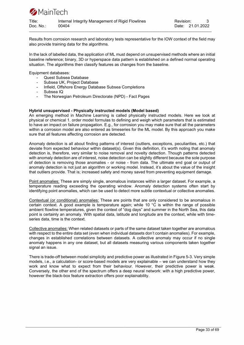
Title: Internal Integrity Management of Rigid Flowlines Revision: 3 Doc. No.: 00404 Date: 21.01.2022 ____________________________________________________________________________________________________
Page 33 of 69
Results from corrosion research and laboratory tests representative for the IOW context of the field may also provide training data for the algorithms. In the lack of labelled data, the application of ML must depend on unsupervised methods where an initial baseline reference; binary, 3D or hyperspace data pattern is established on a defined normal operating situation. The algorithms then classify features as changes from the baseline.
Equipment databases: - Quest Subsea Database - Subsea UK, Project Database - Infield, Offshore Energy Database Subsea Completions - Subsea IQ - The Norwegian Petroleum Directorate (NPD) - Fact Pages
Hybrid unsupervised - Physically instructed models (Model based) An emerging method in Machine Learning is called physically instructed models. Here we look at physical or chemical 1. order model formulas to defining and weigh which parameters that is estimated to have an impact on failure propagation. E.g., for corrosion you may make sure that all the parameters within a corrosion model are also entered as timeseries for the ML model. By this approach you make sure that all features affecting corrosion are detected. Anomaly detection is all about finding patterns of interest (outliers, exceptions, peculiarities, etc.) that deviate from expected behaviour within dataset(s). Given this definition, it’s worth noting that anomaly detection is, therefore, very similar to noise removal and novelty detection. Though patterns detected with anomaly detection are of interest, noise detection can be slightly different because the sole purpose of detection is removing those anomalies - or noise - from data. The ultimate end goal or output of anomaly detection is not just an algorithm or working model. Instead, it’s about the value of the insight that outliers provide. That is; increased safety and money saved from preventing equipment damage. Point anomalies: These are simply single, anomalous instances within a larger dataset. For example, a temperature reading exceeding the operating window. Anomaly detection systems often start by identifying point anomalies, which can be used to detect more subtle contextual or collective anomalies. Contextual (or conditional) anomalies: These are points that are only considered to be anomalous in certain context. A good example is temperature again; while 10 °C is within the range of possible ambient flowline temperatures, given the context of “dog days” and summer in the North Sea, this data point is certainly an anomaly. With spatial data, latitude and longitude are the context, while with time-series data, time is the context. Collective anomalies: When related datasets or parts of the same dataset taken together are anomalous with respect to the entire data set (even when individual datasets don’t contain anomalies). For example, changes in established correlations between datasets. A collective anomaly may occur if no single anomaly happens in any one dataset, but all datasets measuring various components taken together signal an issue. There is trade-off between model simplicity and predictive power as illustrated in Figure 5-3. Very simple models, i.e., a calculation- or score-based models are very explainable – we can understand how they work and know what to expect from their behaviour. However, their predictive power is weak. Conversely, the other end of the spectrum offers a deep neural network: with a high predictive power, however the black-box feature extraction offers poor explainability.

Title: Internal Integrity Management of Rigid Flowlines Revision: 3 Doc. No.: 00404 Date: 21.01.2022 ____________________________________________________________________________________________________
Page 34 of 69
Figure 5-3 Trade-off between model simplicity and predictive power (Matlab) Visualise The analytic of results must be communicated via dashboards or automated via application Interfaces to an ERP or CMMS system. Features, residuals, and trends as well as correlations must be communicated as decision support for flowline asset integrity management. The primary parameters that have the strongest influence on deterioration should be identified and highlighted as they are the ones to focus on in the preventive mitigation efforts. Figure 5-4 and Figure 5-5 show clustering in a binary presentation between two parameters. Note that ML algorithms can handle multivariate correlation in a hyperspace, this is one of the great strengths of the ML method.
Figure 5-4 2D presentation of clustering feature extraction (Matlab)

Title: Internal Integrity Management of Rigid Flowlines Revision: 3 Doc. No.: 00404 Date: 21.01.2022 ____________________________________________________________________________________________________
Page 35 of 69
Deploy maintain and iterate Data input may change from drift or step changes, e.g., if a sensor is replaced a step change may occur. This may alter residuals in the model and create false positive anomalies. The solution is to re-train the ML model in relevant intervals when maintenance work has been made or sensor drift is detected. Hence a process connection between the ML model governance and the maintenance management system must be made. Application of ML for flowlines on the Norwegian shelf A study has been made in a M.Sc. Thesis at the University of Stavanger on Machine Learning based on ILI data from inspection of the Ula to Ekofisk pipeline, based on 2010 ILI data from a 20” ultrasonic inspection tool [38]. Here the student has sought to demonstrate how various types of classification algorithms is used to identify and classify anomalies from ILI inspection data and compare them to the criteria of DNV RP-F101 “corroded pipelines”, to determine structural integrity.
Figure 5-5 Feature correlation matrix from [38].

Title: Internal Integrity Management of Rigid Flowlines Revision: 3 Doc. No.: 00404 Date: 21.01.2022 ____________________________________________________________________________________________________
Page 36 of 69
5.6 Inspection methods for internal integrity
5.6.1 General Flowlines can be inspected from both the external side and internal side. We differ from volumetric and surface inspections. Volumetric inspections are limited to Magnetic Flux Leakage (MFL), Ultrasound Technology (UT), X-ray and tomography methods. Surface inspections relates to Eddie Current (EC), optical and direct measurement techniques. Reference standards for In-line inspection (ILI) are presented in Table 5-5. Table 5-5: Standards for In-line inspection
Standard ID Rev. Name Year Description API STD 1163 [39]
3 In-line Inspection Systems Qualification
2021
This standard covers the qualification, selection, reporting, verification, validation, and use of in-line inspection (ILI) systems for onshore and offshore steel gas and hazardous liquid pipelines. This includes, but is not limited to, tethered, self-propelled, or free-flowing systems for detecting metal loss, cracks, mechanical damage, pipeline geometries, and pipeline location or mapping. The standard applies to both existing and developing technologies.
NACE SP0102
In-Line Inspection of pipelines
2017 This standard provides recommendations to the pipeline operator based on successful, industry-proven practices in ILI.
NACE SP0106 Control of Internal Corrosion in Steel Pipelines and Piping Systems
2018 This standard presents recommended practices for the control of internal corrosion in steel pipelines and piping systems used to gather, transport, or distribute crude oil, petroleum products, or gas. It is meant to serve as a guide for establishing minimum requirements for control of internal corrosion in crude oil gathering and flow lines, crude oil transmission, hydrocarbon products, gas gathering and flow lines, gas transmission, and gas distribution.
Inspection of a pipeline system to monitor the internal condition requires wall thickness measurements. For volumetric inspections, In-Line inspection (ILI) using intelligent pigs are the most common method used. ILI involves the use of instrumented tools to help determine the general condition of the pipeline and to locate areas with potential problems. It is important to keep in mind that ILI has limitations, and it is important to integrate the method with other data sources to verify the pipelines integrity. It is recommended to perform a risk assessment to assist in selecting the preferred integrity methods to assess the identified integrity threats to the pipeline system considered. Several North Sea ILI vendors that provide specialised services for In-Line Inspection of flowlines using different solutions and combination of solutions based on the available technologies described in the below sections e.g.: Baker Hughes, Dacon Inspection, NDE Global, ROSEN, TDW, TSC Subsea. These vendors have different solutions and combinations of solutions based on the following three basic sensing technologies in combination with odometers:
- Magnetic Flux Leakage (MFL) - Ultrasonic technology (UT) - Eddy Current (EC)

Title: Internal Integrity Management of Rigid Flowlines Revision: 3 Doc. No.: 00404 Date: 21.01.2022 ____________________________________________________________________________________________________
Page 37 of 69
The above technologies are often combined, and measurements can be enhanced by: - Calliper direct measuring geometry fingers - Laser profilers - EMAT - Etc.
For difficult to inspect pipelines, bidirectional and tethered ILI tools can be used where it is not possible to run the tool through the flowline from end to end. ILI often entails large operations that require pre-cleaning and handling of large volumes of pumping media. Often these practical issues have not been taken into consideration during engineering and thus constitutes problems for the successful implementation of the inspection. Where ILI cannot be used, external inspection by ROV carried equipment can be employed for volumetric inspection from the external side, either by point techniques or crawlers. These are typical based on UT or CT principles. 5.6.2 MFL – Magnetic flux leakage MFL is the most common technology used to inspect for volumetric metal loss in flowlines. The technology is based on magnetization of the pipe wall in the axial direction and measuring the (change in) magnetic field direction over a metal loss defect (i.e., corrosion) in the pipe wall. Applicability:
− MFL can only be used to inspect ferromagnetic materials only and is therefore not suitable for austenitic corrosion resistant alloys (CRA)
− Diameter range 3" to 56" − Up to velocities of 5 m/s, but preferably between 0.5 and 3 m/s − A rule of thumb states: Wall thickness t[mm] < 1.5 x OD [inch] with an absolute maximum of 40
mm. − Detects both internal- and external metal loss corrosion − Medium: All types (gas, liquid, multi-phase) − Accuracy in the range from 5-10% of wall thickness − Pipeline needs to have a properly cleaned internal surface
5.6.3 UT – Ultrasound technology Ultrasound technology (UT) is used as an ILI tool to measure the absolute thickness of the wall. It operates with a liquid coupling film between the sensors and the wall and is therefore mostly used in pipelines transporting fluids. To inspect gas pipelines, the UT tool must be carried in a liquid plug. The UT-tool requires that the steel surface has been properly cleaned to obtain reliable measurements. The method is restricted by wall thickness and speed. The method also detects cracks. Applicability:
− All pipeline materials − Diameter range 6" to 52” − Velocities up to 2 m/s (preferably between 0.5 and 1 m/s). Higher velocities possible on request
or with lower axial resolution − Nominal Wall thickness typically > 5 mm. Theoretically no maximum wall thickness limit − Minimum detectable remaining wall thickness ≥ 2 mm − Detects both internal- and external metal loss corrosion − Medium: single phase and homogeneous liquid − Gas and multiphase lines can be inspected by running the tool in a batch of liquid − Pipeline needs to have a properly cleaned internal surface

Title: Internal Integrity Management of Rigid Flowlines Revision: 3 Doc. No.: 00404 Date: 21.01.2022 ____________________________________________________________________________________________________
Page 38 of 69
5.6.4 ART – Acoustic resonance technology ART uses a transducer shooting a broadband (multiple frequency) sound signal toward a target such as a pipe wall. The signal duration is sufficiently long to generate oscillations in the target. As the oscillating target continues to be struck by the sound signal, the resonance greatly amplifies the oscillations. The resonating frequencies (frequency domain) are characteristic of the thickness and material of the target and makes it possible to calculate corrosion rates. Applicability:
− Applicable for all materials, including flexibles − Diameter range 10" to 48” − Velocities up to 5 m/s − Nominal Wall thickness up to 75 mm − Depth size accuracy: ±0.4 mm − Medium: gas/ liquid − Can inspect through external coating and internal wax as it does not require contact with the
pipe wall.
5.6.5 EC – Eddy current EC tools have Eddy current sensors that measure lift-off between a probe and the pipe wall. In many cases it is a combination of a mechanical arm (for large area ID variations) and an eddy current sensor at the end (for local ID variations). These tools have been developed as combination tools for the detection and sizing of shallow internal corrosion in heavy walled gas, or multiphase pipelines where MFL and UT face limitations. Applicability:
− Applicable for all materials − Detection and sizing of internal corrosion only, no detection or sizing of external defects − No limitation on wall thickness − Diameter range 6" to 48" − Advised maximum velocity 5 m/s, however no practical limit based on technology, − Medium: All types (gas, liquid, multi-phase) − Defects can be detected and sized (within limits) through a wax or debris layer
5.6.6 EMAT - Electromagnetic acoustic transducer EMAT, or Electromagnetic acoustic transducer, is an Ultrasonic technique (UT) that generates the sound waves in the part inspected, instead of in a transducer. This enables inspection without a fluid coupler between the sensor and pipe wall. It is a non-contact ILI method. The EMAT sensor cannot measure the distance between itself and the pipe surface, meaning that this technology must be combined with other technologies to size defects. EMAT is thus applicable for combined tools. Opportunities and limitations:
− Applicable for all metallic materials − Detection and sizing of internal corrosion only, no detection or sizing of external defects − Wall thickness range 6-18 mm − Diameter range 16" to 48" − Velocity up to 1.5 m/s − Medium: All types (gas, liquid, multi-phase). Non-contact − Defects can be detected through a wax or debris layer − EMAT is mainly used for Stress Corrosion Cracking (SCC) in gas pipelines and coating
disbonding

Title: Internal Integrity Management of Rigid Flowlines Revision: 3 Doc. No.: 00404 Date: 21.01.2022 ____________________________________________________________________________________________________
Page 39 of 69
5.6.7 Combined ILI tools ILI tools usually utilise combined techniques to enhance the feature characterisation and quality of the inspection. The conventional combination ILI tool (geometry and metal loss) allows the detection of geometry features and metal loss in one single ILI run, which is a more economical alternative compared to running the tools in two operations. Unconventional combination tools can include two or more metal loss modules. There are many possible combinations and a description of all will exceed the scope of this report. Basically, the combination must be selected related to the character of the flowline and its operation as well as geometrical and operational constraints. An ILI always require a thorough engineering and planning prior to inspection.
5.6.8 External inspection of internal integrity Verification by external inspection is often very cost efficient in comparison with ILI. However, as these methods only provide information to a small portion of the flowline, care must be taken to place the tool on a thought representative “worst case” section of the flowline. External tools for local inspection of flowlines have emerged over the latest decades and some fine equipment’s are now available for this purpose e.g.: ARTEMIS ® is a subsea external pipeline inspection system using Acoustic Resonance Technology (ART) remotely deployed by ROV. The method can detect both internal and external wall loss without the need for coating removal, which simplifies inspections and reduces cost. Limitations to the technology is related to access to the whole circumference of the pipeline and the inspection speed, meaning that it is mainly suitable for spot checks of unburied pipelines. Statoil research on computer tomography (CT) during the 1990-ties resulted in a ROV carried tool for pipeline inspection. This service is provided by the company Tracerco Ltd with a tool called Tracerco DiscoveryTM. This was first tested in Bergen in April 2013. The advantages are that it inspects through coating, and it is also possible to inspect pipe in pipe bundled flowlines. InnospectionTM has developed a pipeline crawler that combines EC and UT methods. This technology has successfully been employed for subsea flowline inspections.
5.6.9 Spool/equipment retrieval On some occasions it is possible to retrieve a piece of pipe or a tie-in spool. Such items can be of great interest for the inspection engineer to examine and verify the internal condition and corrosion rates. Especially since the actual measurements provides true verification (in opposite to ILI methods where verification is indirect via algorithms). The results are used for evaluation of the field corrosivity.
5.6.10 Selection of inspection method for internal defects in flowlines As can be deducted from the above chapters, the selection of method relates on many parameters and evaluations. Selection of the most appropriate inspection technology for a given application is important. Collection of pipeline data and a clear understanding of inspection objectives are required in the selection process. Pipeline design, operating information and integrity threats need to be carefully reviewed before selecting the ILI or external inspection technology. Table 5-6 below presents an overview of common In-Line inspection tools and their capabilities, whereas Table 5-7 presents which tools are applicable to detect the different types of internal defects relevant for pipelines. The detection / sizing of defects mentioned in Table 5-7 are strongly related to the accuracy of the method used. As an example, if you select to use MFL for inspecting a pipeline with wall-thickness 35mm, then a +/-10% MFL accuracy translates to a minimum detectability of 3,5mm. At an expected corrosion rate in the range of 0,1mm/y this mean that any ILI run within the next 35 years may be

Title: Internal Integrity Management of Rigid Flowlines Revision: 3 Doc. No.: 00404 Date: 21.01.2022 ____________________________________________________________________________________________________
Page 40 of 69
inconclusive related to verifying the expected corrosion rate. Thus, a more accurate method or more verifying activities must be selected for proper integrity management. Table 5-6: Common In-Line inspection tools and capabilities.
Internal defects / Corrosion Material Carbon steel Stainless steel Medium Single Phase liquid Gas/ Multiphase Single
Phase liquid Gas/
Multiphase Wall thickness
WT (mm) < 1,5*OD
(inch) and max 40 mm
WT (mm) >1,5*OD
(inch) or > 40 mm
WT (mm) < 1,5*OD
(inch) and max 40 mm
WT (mm) >1,5*OD
(inch) or > 40 mm
Any WT Any WT
Technique / tool
MFL UT
ART EC
UT ART EC
MFL UT* ART EC
UT* ART EC
UT ART EC
UT* ART EC
Coating ART EC
ART EC
ART EC
ART EC
ART EC
ART EC
*) Must be run in a batch of liquid Table 5-7: Types of ILI tools and inspection purposes for internal integrity issues [40].
Integrity assessment
MFL Tools UT EMAT EC ART
Internal general corrosion
Detection / Sizing
Detection / Sizing
Detection Detection / Sizing
Detection / Sizing
Internal erosion Detection / Sizing
Detection / Sizing
Detection Detection / Sizing
Detection / Sizing
Pitting / Localised
Detection / Sizing
Detection / Sizing
Detection Detection / Sizing
Detection / Sizing
Cracking No detection No detection Detection Detection There are currently three solutions used for ILI pipeline inspections:
1) Free swimming tools where the tool is pumped through the pipeline either by utilising the flow in the pipeline where possible or by applying flow where the pipeline does not have sufficient flow to run the intelligent pig. The advantage of the free-swimming tools is the range and the speed of the inspection.
2) Tethered tools are tools where a cable or tether is used for data transfer and/ or energy supply. The tethered solution has a limitation when it comes to length of the pipeline and the complexity of the pipeline profile. Tethered tools are normally used for pipelines that are difficult to inspect. The pipeline normally cannot be inspected during operation.
3) Robotic tools utilise its own drive unit. The limitation for the robotic tools is related to the length of the pipeline caused by the battery capacity to the tool. The inspection speed of robotic tools is quite slow compared to the free-swimming tools. The pipeline normally cannot be inspected during operation.

Title: Internal Integrity Management of Rigid Flowlines Revision: 3 Doc. No.: 00404 Date: 21.01.2022 ____________________________________________________________________________________________________
Page 41 of 69
5.7 Workflow for integrity management
5.7.1 Regulatory requirements The Activities Regulations from the Norwegian Petroleum Safety Authorities (PSA), paragraphs 45-50, describes how facilities and equipment shall be maintained and classified with regards to health, safety, and environmental consequences of potential functional failures [41]. The different failure modes with failure causes and mechanisms shall be identified, and the probability of failure shall be predicted. The classification shall be used as basis in choosing maintenance activities, and thereunder inspection activities. NORSOK Z-008 Risk based maintenance and consequence classification [42] is the recognised standard described in the guideline of §46 in the activities regulations to be used to fulfil the regulatory requirements. Proposed recommended practices for integrity management of subsea pipeline systems in NORSOK Z-008 (chapter 4.3) is DNVGL-RP-F116 Integrity management of submarine pipeline systems [14]. The linkage between regulatory requirements, NORSOK Z-008 and the DNV RPs is illustrated in Figure 5-6.
Figure 5-6. Regulatory requirements for risk-based inspection planning for subsea pipelines. The recommended practice DNV-RP-F116 provides guidelines, based on requirements as given in DNV-ST-F101, for managing the integrity of submarine rigid steel pipeline systems, and its associated pipeline components during the entire service life. The main focus is on the integrity management process, as presented in Figure 5-7 and Table 5-8; i.e. the combined process of threat identification, risk assessment, planning, inspection, monitoring, testing, integrity assessment, mitigation, intervention, and repair. The whole process should follow a PDCA4 cycle with regular evaluation of results and continuous improvement of the integrity management system.
4 Plan Do Check Act philosophy.

Title: Internal Integrity Management of Rigid Flowlines Revision: 3 Doc. No.: 00404 Date: 21.01.2022 ____________________________________________________________________________________________________
Page 42 of 69
Figure 5-7. Integrity management process [14]. Table 5-8. Integrity management in a PDCA process.
Stage Main stage Sub stage
Plan
Risk Assessment and IM Planning
Data and asset information collection Identify threats for each component Identify one or more barriers for each threat including tasks to verify the barrier Assess probability of failure (PoF) for each component Assess consequence of failure (CoF) for each component Decide risk or criticality for each component including confidence rating Develop integrity management program / work plan IWP (inspection, monitoring, testing, assessment activities)
Do Inspection Monitoring &
Testing Performing inspection, monitoring, testing activities according to plan
Che
ck
Integrity Assessment Regular / yearly evaluation of monitoring, testing and inspection results. Anomalies or un-planned events to be included in assessment with appropriate actions defined
Act
Mitigation Intervention & Repair Initiate mitigation or repair activities if needed.
Review and update risk assessment and plans Continuous improvement of IM system

Title: Internal Integrity Management of Rigid Flowlines Revision: 3 Doc. No.: 00404 Date: 21.01.2022 ____________________________________________________________________________________________________
Page 43 of 69
5.7.2 Risk Assessment and IM Planning To ensure that the risk assessment is done consistently, the risk approach should be documented in strategies and procedures. This is very important when it comes to communication of risk. Such risk documents typically also define risk matrices to be applied and include
• risk categories and interpretation of these including requirements for risk reporting, accountability, and response time guidelines
• acceptable risk level • probability of failure categories and interpretation of these • consequence of failure categories and interpretation of these
General guidance to a risk assessment procedure is presented in DNV RP F116 [14]. Risk matrices varies from company to company. An example is shown in Table 5-9 with five risk categories. The probability categories are ranked from 1 to 5 where 1 relates to the lowest probability of failure. The consequence categories are ranked from A to E where A relates to the lowest consequence of failure. Table 5-9. Example of a risk matrix.
5.7.2.1 Information gathering and threat identification The initial step in a risk assessment is to get an overview of all equipment and components in the pipeline system to be analysed. Then the relevant documents and data should be collected and reviewed to identify applicable threats. Relevant documents are as built documents, material selection reports, DFI resumé, risk analysis (HAZOP/HAZID), drawings, material data sheets, corrosion assessment reports, basis for design, monitoring and testing reports, etc. Relevant corrosion threats depend on the flowline components materials, fluid corrosivity and efficiency of options for corrosion mitigation. The internal corrosion threats applicable for rigid flowlines are discussed in section 5.2. Identification of relevant corrosion threats will already take place during the conceptual design phase as part of the preliminary materials selection and determination of the pipe wall thickness. The need for internal corrosion control and provisions for inspection and monitoring will in that respect also be assessed. The risk assessment and integrity management planning activity should therefore be initiated during the conceptual design and followed up in the subsequent design phases and provide input to the DFI resumes with regards to corrosion threats and provisions for corrosion mitigation and corrosion monitoring.

Title: Internal Integrity Management of Rigid Flowlines Revision: 3 Doc. No.: 00404 Date: 21.01.2022 ____________________________________________________________________________________________________
Page 44 of 69
5.7.2.2 Barrier identification It is recommended that for each of the identified degradation mechanisms (threats), one or more barriers should be in place that allow management of the threat to ALARP. A barrier is defined as a risk control/prevention or a recovery measure. Barriers provide the means of preventing an event or incident, or of mitigating the consequences. A barrier can be an item of equipment or a human intervention and can also be a control on an escalation factor. Barrier categories may be defined as:
1. Material selection or design detailing (e.g., corrosion allowance, resistant material, slope, no crevice)
2. Coating, lining or liner (e.g., non-metallic liner, external coating, TSA) 3. Process control (e.g., dewpoint, flow, temperature, solids) 4. Chemical treatment (e.g., inhibitor injection, BFW oxygen scavenger) 5. Cathodic protection (only relevant externally) 6. Other (e.g., non-return valve) 7. Not Mitigated
Barriers of the mechanical design type (1 and 2) should be managed through maintenance and field inspection (ILI, NDE, etc). Barriers of the process design type (3 and 4) should be managed by process control at operational level and verification of that control by support staff (monitoring). Cathodic protection (5) should be managed through monitoring and condition-based maintenance. For other barriers, the barrier should be closely defined:
- What constitutes the barrier (which equipment does it protect)? - How should the barrier be verified (inspection, measurement, replacement)? - What should be the monitoring frequency?
Each threat should have at least one effective primary barrier and a way to control the barrier. Parameters (i.e., corrosion allowance, corrosion rate, temperature limits, dewpoint, inhibitor concentration) required to monitor and control the barriers within the acceptable limits should be captured and scheduled in an integrity work plan (IWP).

Title: Internal Integrity Management of Rigid Flowlines Revision: 3 Doc. No.: 00404 Date: 21.01.2022 ____________________________________________________________________________________________________
Page 45 of 69
5.7.2.3 Probability of failure assessment The probability of failure (PoF) due to internal corrosion threats depends on the combination of pipeline material and type of fluid transported. The PoF should be considered for each threat and component according to procedure established by the operator. The PoF is by some companies decided based on expected corrosion rates defined by available corrosion models (see section 5.4). If the corrosion rate is found to be same or lower than the design corrosion rate, a low or negligible PoF may be selected as shown in Table 5-10. Table 5-10. Probability of failure categorisation depending on corrosion rate. The actual or expected corrosion rate should be compared to the design corrosion rate, [43].
Probability class Description High > 4 x design CR Actual corrosion rate is very high Medium > 1 – 4 x design CR Actual corrosion rate is high Low 0.5 – 1 x design CR Actual corrosion rate is acceptable/low Negligible < 0.5 x design CR Actual corrosion rate is very low
The level-1 flow chart assessment from DNV-RP-F116 shown in Figure 5-8 is another method for PoF decision, which considers the time since last ILI inspection combined with corrosion control and monitoring data program.
Figure 5-8. Probability of failure decision flow chart for internal corrosion gas export [14].

Title: Internal Integrity Management of Rigid Flowlines Revision: 3 Doc. No.: 00404 Date: 21.01.2022 ____________________________________________________________________________________________________
Page 46 of 69
5.7.2.4 Consequence of failure assessment The consequence of failure (CoF) should be considered for each threat and component according to procedure established by the operator. The consequence categories and qualitative ranking scales normally considered for flowlines are given in Table 5-11 and Table 5-12, respectively. Table 5-11. CoF categories normally considered in the risk assessment.
Category Description Asset Economic consequences resulting from loss of primary containment mainly related
to deferred or reduced production and costs related to unanticipated intervention, mitigations, and repairs.
Safety Health and safety consequences resulting from loss of primary containment and based on the average number of personnel present in the area of concern.
Environment Environmental consequences after release of production fluids (oil, gas) resulting from loss of primary containment.
Reputation Reputational consequences of an incident.
Table 5-12. CoF ranking scales, example.
Rank Safety Assets Environment Reputation
1/A/L Insignificant Insignificant Insignificant Insignificant
2/B/M Slight/minor injury Slight/minor damage Slight/minor effect Slight/minor impact
3/C/H Major injury Local damage Local effect Considerable impact 4/D/VH Single fatality Major damage Major effect Major impact
5/E/EH Multiple fatalities Extensive damage Massive effect Major international impact
DNV-RP-F116 provides guidance and ideas to different CoF assessment levels as shown in Table 5-13. These can be used as input to develop risk assessment methods to be included in company governing documentation. More simple qualitative assessments may be used and are generally considered to be sufficient in the context of submarine pipeline integrity management. Table 5-13. CoF assessment levels modelling presented in DNV RP F116.
CoF Assessment level Comment Level 1 Aggregated
option - Easy assessment, less flexible. - Uses Safety Class model according to DNVGL-ST-F101. - One consequence category is used to represent the safety,
environmental and economic consequences. Segregated option
- More detailed assessment, more flexible. - Safety, environmental and economy consequence is addressed
separately. Level 2 Combination of the two options in level1; safety class, personnel,
environmental and economic consequences

Title: Internal Integrity Management of Rigid Flowlines Revision: 3 Doc. No.: 00404 Date: 21.01.2022 ____________________________________________________________________________________________________
Page 47 of 69
5.7.2.5 Risk decision and integrity work plan development The risk or criticality is the product of PoF and CoF as shown in the example risk matrix in Table 5-9. The inspection programs are developed based on the results from the risk assessment. The recommended inspection intervals based on the risk location in the risk matrix should be defined by the operator. Table 5-14 gives an example of inspection intervals based on the risk matrix in Table 5-9, where N/A corresponds to a Not Acceptable risk. Table 5-14. Example of inspection intervals based on a risk matrix, [14].
In the risk-based methodology developed by Shell the inspection interval is calculated based on remnant life and an interval factor as shown in Figure 5-9, [43]. The interval factor is a function of criticality/risk level and confidence rating. The resulting total confidence score increases or decreases the interval factor which determines the inspection interval. The confidence rating reflects how much the inspector and the materials corrosion engineer trust in the predicted corrosion rates. A high confidence would yield longer inspection intervals. The suggested confidence rating includes an evaluation on:
• stability and predictability of the degradation mechanisms. • number and quality of inspections carried out. • if reliable process (integrity operating window) monitoring is carried out.

Title: Internal Integrity Management of Rigid Flowlines Revision: 3 Doc. No.: 00404 Date: 21.01.2022 ____________________________________________________________________________________________________
Page 48 of 69
Figure 5-9. Inspection interval determination based on criticality, confidence and remnant life as developed by Shell Global Solutions [43]. The applicable inspection methods are discussed in section 5.6. Inline inspection pigging with a combination of tools (MFL, ET, UT) is normally selected for pipeline inspections. However, external NDE methods could also serve as valuable and cost-effective monitoring of the internal condition. An integrity work plan (IWP) should be developed which includes the risk-based inspection activities (ILI or NDE inspection) as well as condition monitoring, testing, assessment activities. Condition monitoring activities should be carried out to collect operational data and other type of information indicating the condition of a component. The monitoring activities should be linked to threats and barriers (see section 5.7.2.2) to clarify the reason for why the activity needs to be done. Also, acceptable limits should be defined to initiate mitigating actions if the monitoring parameters show values outside critical limits.

Title: Internal Integrity Management of Rigid Flowlines Revision: 3 Doc. No.: 00404 Date: 21.01.2022 ____________________________________________________________________________________________________
Page 49 of 69
Examples of condition monitoring activities to be included in the IWP: - Sampling and analysis of fluid composition (e.g., CO2, H2S, organic acids, O2, cations as Fe-ions,
anions (Chlorides), water content, alkalinity, pH, water dew point (online)) - Process parameters (flow, pressure, temperature, water cut) - Sand monitoring (erosion probes, acoustic sand sensors) - Corrosion monitoring
o Monitoring the fluid corrosivity corrosion tests electrical resistance (ER) probes weight loss coupons linear polarisation resistance (LPR) probes hydrogen probes
- Corrosion inhibitor monitoring. o Controlling corrosion inhibitor concentration (residual and active components) o Checking the injection rate and tank volume (running of pumps, tank level indicator, flow
rate) - Bacteria sampling and analysis - Biocide treatment More information about condition monitoring can be found in Table 8-6.
5.7.3 Inspection, Monitoring & Testing This is the execution part of the integrity management system. The inspection, monitoring, testing activities should be performed according to the risk assessment and integrity work plan (IWP) established in section 5.7.2.5 above. The results should be documented.
5.7.4 Integrity Assessment Integrity assessment should be done on regular basis, minimum yearly. Then an evaluation of all results from monitoring, testing and inspection should be performed: - Have the condition monitoring parameters been within acceptable limits? - Re-run corrosion models with updated input values (CO2, H2S, flow, pressure, temperature, water
content, sand, etc). The calculated corrosion rate would be input to updated PoF and inspection due date.
- Assess corrosion monitoring probes and corrosion test results - Evaluate inspection results related to the method Probability of Detection (PoD)
o External ROV inspection if relevant for internal conditions (coating damages, TOL corrosion)
o Any ILI, if performed o NDE on subsea sections, if performed o Any CVI or NDE inspections performed topside relevant for the pipeline.
- Any impact from maintenance activities, modification, or repairs? - Any changes in operation or process conditions? - Anomalies or un-planned events to be included in assessment with appropriate actions defined The integrity assessment should be properly documented to ensure traceability for later assessment or life extensions. Good communication lines and collaboration between different disciplines in the topside and subsea organisation is important for a successful integrity management of the pipeline.

Title: Internal Integrity Management of Rigid Flowlines Revision: 3 Doc. No.: 00404 Date: 21.01.2022 ____________________________________________________________________________________________________
Page 50 of 69
5.7.5 Mitigation Intervention & Repair Mitigation or repair activities should be initiated if needed. The flowline operator has a set of measures to act on keeping deterioration and risk within acceptable limits:
- Adjusting parameters (flow, temperature, pressure (MAOP)) - Chemical treatment (pH, corrosion inhibitor, glycol, scale, etc.) - Removing water by physical pigging - Removing deposits by physical pigging - Removing water and deposits with dynamic5 pigging - Increasing insulation (burial) - Removing acids - Etc.
5.7.5.1 Corrosion tolerance and de-rating The allowable defect standards as; B31G [44], RSTRENG [45] and DNV RP F101 [46] in combination with inspection results can be utilised to determine a corrosion tolerance that exceeds a given design general corrosion allowance of the flowline. If the nature of the corrosion attack is verified or expected to be local, formed as a pit or a groove, this will not affect the hoop stress pressure capacity of the flowline as much as if it was a general thinning of the circumference of the pipe wall. By utilising this principle, a lower risk can be demonstrated for ageing flowlines. Another possibility to lower risk is to formally derate the flowline MAOP. This is often possible for aging flowlines, as reservoir pressure reduces over time.
5.7.6 Review and update risk assessment and plans As part of the yearly integrity assessment the risk assessment program and integrity work plan should be reviewed and updated as required. The evaluation of historical inspection and process data, learnings from root cause investigations and new knowledge from research activities and standardisation is key elements for continuous improvement of the integrity management system.
5 Dynamic pigging - pulsation of flow to sweep out liquids and deposits at low point areas.

Title: Internal Integrity Management of Rigid Flowlines Revision: 3 Doc. No.: 00404 Date: 21.01.2022 ____________________________________________________________________________________________________
Page 51 of 69
6 FUTURE IN FLOWLINE INTEGRITY MANAGEMENT
6.1 The unknown unknowns In general, all our wisdom as interpretations of reality, assumptions, and decisions, are based on harvested knowledge and experience. The unknown threats lurk in the areas where we are not aware that we lack information or knowledge, or where we believe that the facts that we base our decisions on are true when they are not – the unknown unknowns. These events cover:
− The unknown unknowns – events that are unknown to all − Unknown knowns – events that we failed to include in our risk assessment or design − Knowns, but with assumed negligible probability of occurrence
The process of knowing changes the unknown facts into the fact known. What is regarded as “proven facts” often changes by time as their adequacies are challenged by new and better methods and equipment, as well as new experience. One example being CRA corrosion tests in the 1980ties where the importance of controlling oxygen to ppb level was not yet understood. Referring to some of these or older tests today is thus not always adequate as new and revised knowledge to oxygen freeing and expected results from current tests gives other conclusions and revised updated knowledge and “proven facts”. It is the corrosion engineer “subject matter expertise” to know when old research is not valid. (However, the old research results with now wrong conclusions are still available to be wrongfully applied by non-subject matter experts). Twenty years from now the present facts is likely to have changed further, as they are constantly challenged, and new experience has been reflected upon.
All of human knowledge consists of actions and products of acts in which men and women participate with other human beings, with animals and plants, as well as objects of all types, in any environment. Men and women have, are, and will present their acts of knowing and known in language. Generic people, and specific men and women, are known to be vulnerable to error. Consequently, all knowledge (knowing and known) whether commonsensical or scientific; past, present, or future; is subject to further inquiry, examination, review, and revision.
Quote: Knowing and the known, John Dewey 1949 To improve our knowledge and wisdom in flowline integrity management, we constantly need to ask ourselves three questions in the following order:
1. Are we doing integrity management things? 2. Are we doing the integrity management things right? 3. Are we doing the right integrity management things?
Doing things right involves establishing a two circuit continuously improving learning process to challenge and revise our activities related to improving knowledge as described in chapter 5.7. Failure happens as surprises (black swans) when experience, engineering operating practice and monitoring observation fails to scope out and identify development of failure mechanisms. A black swan is a highly improbable event with three principal characteristics: It is unpredictable; it carries a massive consequential impact; and, after it has occurred; we concoct an explanation that makes it appear less random, and more predictable, than it was. Why do we not acknowledge the phenomenon of black swans until after they occur? Part of the answer, according to Taleb [47], is that humans are hardwired to learn specifics when they should be focused on generalities. We concentrate on things we already know, and time and time again fail to take into consideration what we don't know. We are, therefore, unable to truly estimate opportunities, too vulnerable to the impulse to simplify, narrate, and categorize, and not open enough to rewarding those who can imagine the impossible [47].

Title: Internal Integrity Management of Rigid Flowlines Revision: 3 Doc. No.: 00404 Date: 21.01.2022 ____________________________________________________________________________________________________
Page 52 of 69
At low oil and gas prices, operators tend to cut costs and regroup their activities. At such times it may be tempting to reduce activities not directly contributing to short term financial results, or in investments that cannot be proven in terms of financial return e.g.:
− Reduction in inspection budgets − Reduction in maintenance budgets − Reduction in work training − Reduction in research
Cost savings in integrity management activities simply means that the company now accepts a higher level of uncertainty and corresponding risk. This may increase the exposure to losses, near misses, and the occasionally black swan. Example of an unknown unknown: The Pertamina Tunu gas field in Thailand came on stream in 1978. The field has two wet-gas flowlines that crosses the Mahakam River at different locations. The flowlines were treated with corrosion inhibitor and the corrosion probes show insignificant corrosion rates at both ends of the flowline. However, during an in-line inspection of the flowlines, it was discovered severe top of line corrosion attacks at locations where the flowlines crossed the river. A root cause analysis revealed that the flowlines had been unburied and directly exposed to the fast-flowing water in the river. This cooled the flowlines and resulted in high condensation rates, and corresponding high local top of line corrosion rates [48]. The severe top of line corrosion was unforeseen from design because knowledge about top of line corrosion had not developed far in the late 1970ties, and the pipeline was not supposed to be exposed to the river water. During operations top of line corrosion was not detected because the corrosion management strategy of using corrosion inhibitor and monitoring corrosion rates at the pipeline ends was not effective to detect top of line corrosion. Top of line corrosion was experienced as early as 1960 (Lacq sour gas field in France), however this knowledge was not shared until 1981, [49]. The experiences from the Pertamina Tunu field were shared with the oil and gas industry through scientific papers given at conferences and has together with research at e.g., IFE contributed to the present subject knowledge applied to flowlines at the Norwegian shelf. Today TOL corrosion is a known threat that has focus within engineering design. This shows the importance of international knowledge sharing in the industry, as well as research, to collectively improve on safety. One learning from the last 30 years of operation of flowlines on the Norwegian shelf is that risk taking by application of new technology sometimes fail, because all aspects of the novel application was not fully known and understood at the time of application. Examples are: − HISC and weld cracks experienced in the application of novel materials 25Cr SDSS, / 13Cr SMSS − Failure in dependent subsea sensor systems
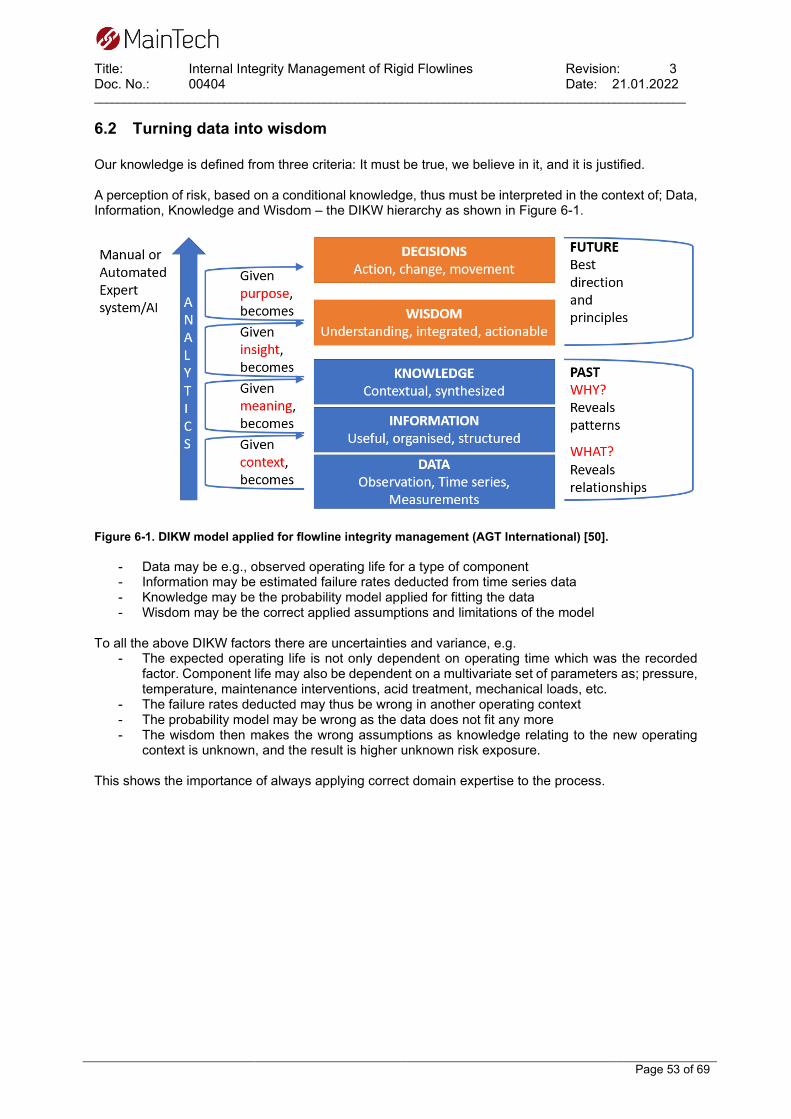
Title: Internal Integrity Management of Rigid Flowlines Revision: 3 Doc. No.: 00404 Date: 21.01.2022 ____________________________________________________________________________________________________
Page 53 of 69
6.2 Turning data into wisdom Our knowledge is defined from three criteria: It must be true, we believe in it, and it is justified. A perception of risk, based on a conditional knowledge, thus must be interpreted in the context of; Data, Information, Knowledge and Wisdom – the DIKW hierarchy as shown in Figure 6-1.
Figure 6-1. DIKW model applied for flowline integrity management (AGT International) [50].
- Data may be e.g., observed operating life for a type of component - Information may be estimated failure rates deducted from time series data - Knowledge may be the probability model applied for fitting the data - Wisdom may be the correct applied assumptions and limitations of the model
To all the above DIKW factors there are uncertainties and variance, e.g.
- The expected operating life is not only dependent on operating time which was the recorded factor. Component life may also be dependent on a multivariate set of parameters as; pressure, temperature, maintenance interventions, acid treatment, mechanical loads, etc.
- The failure rates deducted may thus be wrong in another operating context - The probability model may be wrong as the data does not fit any more - The wisdom then makes the wrong assumptions as knowledge relating to the new operating
context is unknown, and the result is higher unknown risk exposure. This shows the importance of always applying correct domain expertise to the process.

Title: Internal Integrity Management of Rigid Flowlines Revision: 3 Doc. No.: 00404 Date: 21.01.2022 ____________________________________________________________________________________________________
Page 54 of 69
6.3 Collective mindfulness Handling the black swans and unknown calls for a collective mindful organisation and work processes. Organisational mindfulness is described as the extent to which an organisation can assess threats that may emerge and capture such detail, so they are able to respond quickly and reliably to prevent incidents or system failures. Collective mindfulness is manifest in organisations by the workforce being sensitive to changes in the environment, continuously updating the way staff think and perceive things and by appreciating the importance of context. The five principles of collective mindfulness as defined by Weick & Sutcliffe - Managing the unexpected: [51]
− Preoccupation with failure > Seek to understand failure − Reluctance to simplify > Manage variation and signs of the unexpected − Sensitivity to operations > Maintain skilled operators with high awareness − Commitment to resilience > Maintain responsiveness to incidents − Deference to expertise > Have experts available and apply them when needed
The five principles do not operate in isolation nor are stand-alone elements. They must be enhanced through a complex systems-thinking lens focused on understanding that social-network interactions and building collective-mindful relationships is required to enable critical co-occurrences to be managed.

Title: Internal Integrity Management of Rigid Flowlines Revision: 3 Doc. No.: 00404 Date: 21.01.2022 ____________________________________________________________________________________________________
Page 55 of 69
6.4 How to meet the future So how should we then proceed in future integrity management and technology development, without being over conservative relating only to established solutions? We must first look back to look ahead for the future. We have learned that the following activities are indeed working:
− Tripartite cooperation, government, operator, unions − Two circuit continuously improvement learning processes for integrity management − Sharing knowledge in JIP’s, conferences, and papers − Standardisation − Maintaining and expanding domain knowledge − Performing research to improve on knowledge − Conducting Root Cause Analysis to learn from failure − Registrations of quality data in shared databases − Being conservative – use proven solutions − See the big picture; engineering, installation, operation, and maintenance when selecting
solutions In the future we must establish a driving momentum in the continuation of these processes. The path to more wisdom always lies in analysing more data to gain more knowledge as shown in fig. 6.1. The new enhanced interconnectivity and big-data analytic methods present an opportunity to escalate the learning process and allows us to learn and analyse from much larger amounts of data. This path will generate more knowledge to give more accurate wisdom, for us to make better decisions in the future. The enablers are:
− Harvesting more data in general − Harvesting time series data from physical- chemical sensors applying IIoT − Contextualising data to integrity operational window or physical domain − Sharing data and knowledge − Machine Learning big data analytics − Physical and chemical guided Machine Learning predictions − More thorough engineering – systems engineering approach − Failure mode and effect analysis − Failure mode and symptoms analysis − Physical- chemical models, flow, corrosion, erosion, heat transfer etc. − digital twin simulations − Expert system logics for diagnostics − Make sure knowledge is harvested, revised, shared and not forgotten

Title: Internal Integrity Management of Rigid Flowlines Revision: 3 Doc. No.: 00404 Date: 21.01.2022 ____________________________________________________________________________________________________
Page 56 of 69
7 REFERENCES [1] P. Bang, “The development of the current regime, historical review,” PSA, 2019. [2] The Hon. Lord Cullen, “The Public Inquiry into the Piper Alpha Disaster,” Department of Energy,
1990. [3] J. Vinnem, “On the analysis of hydrocarbon leaks in the Norwegian offshore industry,” UiS,
Stavanger, 2012. [4] Petroleumstilsynet (PSA), “Risikonivå i petroleumsvirksomheten Hovedrapport, utviklingstrekk
2020, norsk sokkel,” PSA, 2021. [5] T. Garten, J. Picksley, I. MacLeod, J003108-01-IM-REP-001, “Subsea Integrity Management -
Wellhead to Topside ESDV,” Wood. commissioned by PSA, 2020. [6] DNV-RP-F112, “DESIGN OF DUPLEX STAINLESS STEEL SUBSEA EQUIPMENT EXPOSED
TO CATHODIC PROTECTION,” DNV, 2008. [7] T. Rogne and et al, “Corrosion performance for 13Cr stainless steel,” Corrosion, p. 00152, 2000. [8] T. H. G. R. P. K. T. H. a. O. Ø. I. Grytdal, “Examination of 13% Cr flowlines in service: HISC
sensitivity and NDT techniques for inspection of flowlines in service,” Pipeline Technology Conference Ostend, Paper 2009-103, 2009.
[9] H. W. H. P. B. G. W. Thor-Ståle Kristiansen, “Combined Ultrasonic Tethered Tool for Inspection of Weld Cracks in Offshore Pipelines: Tool Qualification and First Inspection Results from Offshore Inspection,” Pipeline Technology Conference 2015, 2015.
[10] R. Mollan, “Experince with 13Cr supermartensitic stainless steel in the Tune submarine flowlines,” NACE International, Corrosion Paper no 05092, 2005.
[11] P. O. Gartland and J. E. Salomonsen, “A Pipeline Integrity Management Strategy Based on Multiphase Fluid Flow & Corrosion Modelling,” NACE CORROSION 99, paper no 99622, 1999.
[12] NORSOK M-001, Ed. 5, “Materials selection,” Standards Norway, 2014. [13] ISO 21457, Materials selection and corrosion control for oil and gas production systems,
International Organization for Standardization, 2010. [14] DNVGL-RP-F116, Integrity management of submarine pipeline systems, 2017: DNVGL. [15] Y. Bai and Q. Bai, Subsea Pipeline Integrity and Risk Management, Elsevier, 2014. [16] A. M. El-Sherik, Trends in Oil and Gas Corrosion Research and Technologies, Elsevier, 2017. [17] A. H. Obot and B. Al-MoubarakiI, “Top of the line corrosion: causes, mechanisms,and mitigation
using corrosion inhibitors,” Arabian Journal of Chemistry, p. 103116, 2021. [18] R.Nyborg and A. Dugstad, CORROSION paper no 07555, “Top of Line Corrosion and Water
Condensation Rates in Wet Gas Pipelines,” NACE International, 2007. [19] M. Seiersten, A. Dugstad, J. Nossen and O. Sendstad, IFE, “Top of line corrosion in gas-
condensate pipelines,” COTech & OGTech 2021, 2021. [20] M. Sliem and al et, “Monitoring of under deposit corrosion for the oil and gas industry: A review,”
Journal of Petroleum Science and Engineering, p. 108752, 2021. [21] R. Jiaa and et al, “Microbiologically influenced corrosion and current mitigation strategies: A state
of the art review,” International Biodeterioration & Biodegradation, pp. 42-48, 2019. [22] B. N. Popov, Corrosion Engineering - Principles and Solved Problems, Elsevier, 2015. [23] H. Husby and et al, “Corrosion of 22%Cr and 25%Cr duplex stainless steel in produced water
with small amounts of oxygen,” 16th Nordic Corrosion Congress, Stavanger, 2015. [24] ISO 15156-1, “Materials for use in H2S-containing environments in oil and gas production — Part
1: General principles for selection of cracking-resistant materials,” ISO, 2020. [25] ISO 15156-3, Materials for use in H2S-containing environments in oil and gas production — Part
3: Cracking-resistant CRAs and other alloys, International Organization for Standardization, 2020.
[26] ISO 15156-2, “Materials for use in H2S-containing environments in oil and gas production — Part 2: Cracking-resistant carbon and low-alloy steels, and the use of cast irons,” ISO, 2020.

Title: Internal Integrity Management of Rigid Flowlines Revision: 3 Doc. No.: 00404 Date: 21.01.2022 ____________________________________________________________________________________________________
Page 57 of 69
[27] J. Enerhaug and et al, “Robustnes of supermartensitic stainless steel girth welds - Experience from the Kristin field development project,” Corrosion, p. 05097, 2005.
[28] R. Case and D. R. McIntyre, “Mercury Liquid Metal Embrittlement Of Alloys For Oil And Gas Production And Processing,” CORROSION , pp. NACE-10294, 2010.
[29] DNVGL-RP-O501, Managing sand production and erosion, DNVGL, 2015. [30] NORSOK P-002, Process system design, Standard Norge, 2014. [31] API 14E, Offshore Production Platform Piping Systems, API, 2020. [32] IFE/KR/E - 2009/003 (Nyborg, Dugstad), “Guidelines for prediction of CO2 corrosion in oil and
gas production systems,” IFE, 2009. [33] NACE paper 10371; R. Nyborg, “CO2 CORROSION MODELS FOR OIL AND GAS
PRODUCTION SYSTEMS,” NACE International, 2010. [34] NORSOK M-506, ed. 3, “CO2 corrosion rate calculation model,” Standards Norway, 2017. [35] A. Rachman et. al, “Applications of machine learning in pipeline integrity management: A state-
of-the-art-review,” International Journal of Pressure Vessel and Piping, 2021. [36] K.Øyen, P.Schølberg et al. rapport A8222, “Vedlikehold som virkemiddel for å hindre
storulykker,” SINTEF and PSA, 2008. [37] SINTEF A 15322; P. Hokstad, S. Håbrekke, R. Johnsen, S. Sangesland, “Ageing and life
extension for offshore facilities in general and for specific systems,” SINTEF/PSA, 2010. [38] P. Sandmark (M.Sc. thesis), “Use of Machine Learning Techniques for Risk Based Inspection
and IntegrityManagement of Pipeline Systems,” University in Stavanger, 2019. [39] API STD 1163, In-Line Inspection Systems Qualifiction, API, 2021. [40] NACE SP0102, In-Line Inspection of Pipelines, 2017. [41] The activities regulations, “Regulations relating to conducting petroleum activities,” 2020.
[Online]. Available: https://www.ptil.no/contentassets/f18375b7184d4cd68fc1c733b318b3dc/aktivitetsforskriften_e-21.pdf.
[42] NORSOK Z-008, Risk based maintenance and consequence classification, Standard Norge, 2017.
[43] M. Festen, Shell Global Solutions, “DOKUMENTS,” 2002. [Online]. Available: https://vdocuments.mx/shell-rbi-methodology.html.
[44] B31G, “Manual for Determining the Remaining Strength of Corroded Pipelines,” ASME, 2012. [45] PRCI RSTRENG® corrosion assessment tool, “Technical Toolboxes, distribution,” [Online].
Available: https://technicaltoolboxes.com/rstreng/. [46] DNV-RP-F101, “Corroded pipeline,” DNV, 2021. [47] N. N. Taleb, “The Black Swan - The Impact of the Highly Improbable,” ISBN: 9780812973815,
2010, 2nd edition. [48] Y. M. Gunaltun and D. Supriyatman, “Top of the Line Corrosion in Multiphase Gas Lines: A Case
History,” Corrosion 99, pp. NACE-99036, 1999. [49] M. Estavoyer, “Corrosion problems at Lacq sour gas field, H2S corrosion in oil & gas production,”
NACE International, 1981. [50] “The DIKW model for knowledge management and data value extraction,” [Online]. Available:
https://www.i-scoop.eu/big-data-action-value-context/dikw-model/. [51] W. K. &. Sutcliffe, Managing the Unexpected: Sustained Performance in a Complex World, 3rd
edn., John Wiley & Sons Inc, New Jersey, 2015.

Title: Internal Integrity Management of Rigid Flowlines Revision: 3 Doc. No.: 00404 Date: 21.01.2022 ____________________________________________________________________________________________________
Page 58 of 69
8 APPENDIX
8.1 Appendix 1 – Relevant standards Table 8-1 Relevant NORSOK Standards Standard ID Rev. Name Year Main points / description NORSOK U-009
1 Lifetime extension for subsea systems
2011 Provides general principles for assessing an extension of service life beyond the original service life of subsea systems
NORSOK Y-002
2 Lifetime extension for transportation systems
2021 Provides guidance and requirements for assuring technical integrity of the transportation system beyond the original service life
NORSOK M-001
5 Material selection 2014 Provides guidance and requirements for material selection and corrosion protection for hydrocarbon production, including subsea production systems.
NORSOK M-506
3 CO2 corrosion rate calculation model
2017 Provides a recommended practice for calculation of corrosion rates in hydrocarbon production and process systems where the corrosive agent is CO2
NORSOK P-002
1 PROCESS SYSTEM DESIGN
2014 Provides guidelines on flow velocity limitation to avoid erosion, water-hammer pressure surges, noise, vibration and reaction forces.
Table 8-2 Relevant DNV recommended practices
ID. Rev. Name Year Main points / description DNVGL-RP-0002
Integrity Management of Subsea Production System
2019 Provides recommendations for managing the integrity of subsea production systems including: threat identification, risk assessment, inspection, monitoring and testing activities, testing and mitigation, intervention and repair.
DNVGL-ST-F101 (Previously OS-F101)
Submarine Pipeline Design
2017
Provides recommendations on concept development, design, construction, operation and abandonment of Submarine Pipeline Systems
DNV-RP-O501
Managing sand production and erosion
2021 Provides guidance on how to manage the consequences of sand production and erosion of oil and gas production facilities.
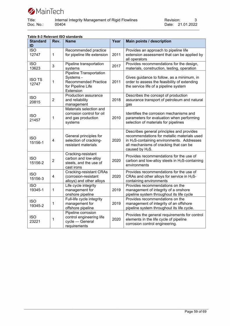
Title: Internal Integrity Management of Rigid Flowlines Revision: 3 Doc. No.: 00404 Date: 21.01.2022 ____________________________________________________________________________________________________
Page 59 of 69
Table 8-3 Relevant ISO standards Standard ID
Rev. Name Year Main points / description
ISO 12747
1 Recommended practice for pipeline life extension
2011 Provides an approach to pipeline life extension assessment that can be applied by all operators
ISO 13623 3 Pipeline transportation
systems 2017 Provides recommendations for the design, materials, construction, testing, operation
ISO TS 12747 1
Pipeline Transportation Systems - Recommended Practice for Pipeline Life Extension
2011 Gives guidance to follow, as a minimum, in order to assess the feasibility of extending the service life of a pipeline system
ISO 20815 2
Production assurance and reliability management
2018 Describes the concept of production assurance transport of petroleum and natural gas
ISO 21457 1
Materials selection and corrosion control for oil and gas production systems
2010 Identifies the corrosion mechanisms and parameters for evaluation when performing selection of materials for pipelines
ISO 15156-1 4
General principles for selection of cracking-resistant materials
2020
Describes general principles and provides recommendations for metallic materials used in H2S-containing environments. Addresses all mechanisms of cracking that can be caused by H2S.
ISO 15156-2 2
Cracking-resistant carbon and low-alloy steels, and the use of cast irons
2020 Provides recommendations for the use of carbon and low-alloy steels in H2S-containing environments
ISO 15156-3 4
Cracking-resistant CRAs (corrosion-resistant alloys) and other alloys
2020 Provides recommendations for the use of CRAs and other alloys for service in H2S-containing environments
ISO 19345-1
1 Life cycle integrity management for onshore pipeline
2019 Provides recommendations on the management of integrity of a onshore pipeline system throughout its life cycle
ISO 19345-2 1
Full-life cycle integrity management for offshore pipeline
2019 Provides recommendations on the management of integrity of an offshore pipeline system throughout its life cycle.
ISO 23221 1
Pipeline corrosion control engineering life cycle — General requirements
2020 Provides the general requirements for control elements in the life cycle of pipeline corrosion control engineering.
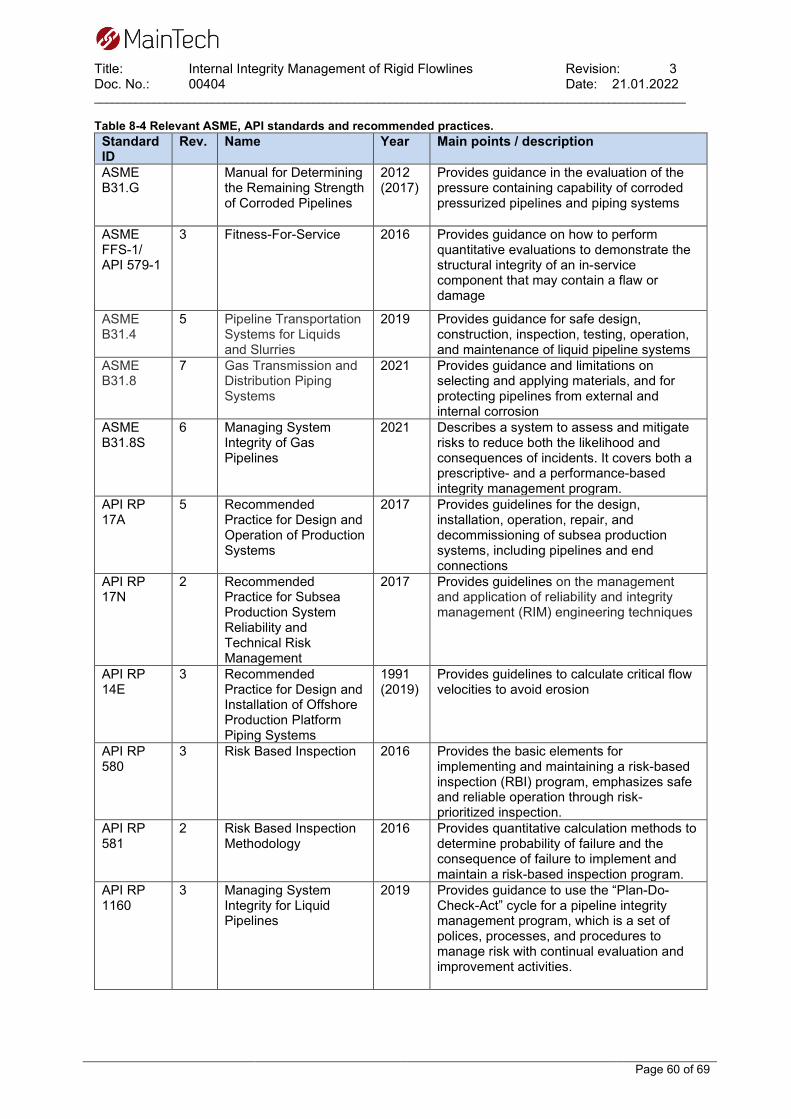
Title: Internal Integrity Management of Rigid Flowlines Revision: 3 Doc. No.: 00404 Date: 21.01.2022 ____________________________________________________________________________________________________
Page 60 of 69
Table 8-4 Relevant ASME, API standards and recommended practices. Standard ID
Rev. Name Year Main points / description
ASME B31.G
Manual for Determining the Remaining Strength of Corroded Pipelines
2012 (2017)
Provides guidance in the evaluation of the pressure containing capability of corroded pressurized pipelines and piping systems
ASME FFS-1/ API 579-1
3 Fitness-For-Service 2016 Provides guidance on how to perform quantitative evaluations to demonstrate the structural integrity of an in-service component that may contain a flaw or damage
ASME B31.4
5 Pipeline Transportation Systems for Liquids and Slurries
2019 Provides guidance for safe design, construction, inspection, testing, operation, and maintenance of liquid pipeline systems
ASME B31.8
7 Gas Transmission and Distribution Piping Systems
2021 Provides guidance and limitations on selecting and applying materials, and for protecting pipelines from external and internal corrosion
ASME B31.8S
6 Managing System Integrity of Gas Pipelines
2021 Describes a system to assess and mitigate risks to reduce both the likelihood and consequences of incidents. It covers both a prescriptive- and a performance-based integrity management program.
API RP 17A
5 Recommended Practice for Design and Operation of Production Systems
2017 Provides guidelines for the design, installation, operation, repair, and decommissioning of subsea production systems, including pipelines and end connections
API RP 17N
2 Recommended Practice for Subsea Production System Reliability and Technical Risk Management
2017 Provides guidelines on the management and application of reliability and integrity management (RIM) engineering techniques
API RP 14E
3 Recommended Practice for Design and Installation of Offshore Production Platform Piping Systems
1991 (2019)
Provides guidelines to calculate critical flow velocities to avoid erosion
API RP 580
3 Risk Based Inspection 2016 Provides the basic elements for implementing and maintaining a risk-based inspection (RBI) program, emphasizes safe and reliable operation through risk-prioritized inspection.
API RP 581
2 Risk Based Inspection Methodology
2016 Provides quantitative calculation methods to determine probability of failure and the consequence of failure to implement and maintain a risk-based inspection program.
API RP 1160
3 Managing System Integrity for Liquid Pipelines
2019 Provides guidance to use the “Plan-Do-Check-Act” cycle for a pipeline integrity management program, which is a set of polices, processes, and procedures to manage risk with continual evaluation and improvement activities.

Title: Internal Integrity Management of Rigid Flowlines Revision: 3 Doc. No.: 00404 Date: 21.01.2022 ____________________________________________________________________________________________________
Page 61 of 69
Table 8-5 Relevant UK legislation Standard ID Name Year Main points / description STATUTORY INSTRUMENTS 2015 No. 483
The Control of Major Accident Hazards Regulations 2015
2015 Provides regulations to prevent major accidents that are required to be followed in Great Britain
STATUTORY INSTRUMENTS 2015 No. 1393
The Control of Major Accident Hazards (Amendment) Regulations 2015
2015 Provides regulations to prevent major accidents that are required to be followed in Great Britain
STATUTORY INSTRUMENTS 1996 No. 825
The Pipelines Safety Regulations 1996
1996 Provides regulations regarding the design and operation of pipelines that are required to be followed in Great Britain
STATUTORY INSTRUMENTS 2015 No. 398
The Offshore Installations (Offshore Safety Directive) (Safety Case etc.) Regulations 2015
2015 Provides regulations regarding the operation of pipelines that are required to be followed in Great Britain
Title: Internal Integrity Management of Rigid Flowlines Revision: 3 Doc. No.: 00404 Date: 21.01.2022 ____________________________________________________________________________________________________
Page 62 of 69
8.2 Appendix 2 - CO2 corrosion models – update from IFE
Memo Corrosion – 36/2021 To: Maintech From: Rolf Nyborg, IFE Date: 2021-11-24
CO2 corrosion prediction models for oil and gas pipelines Scope of work Maintech has asked IFE to prepare a chapter on corrosion models for a report on integrity management of pipelines. The memo/chapter should include a short summary of status for corrosion models currently in use, e.g. de Waard, NORSOK, Hydrocor etc. It is referred to the IFE report IFE/KR/E – 2009/003. The memo should describe current status of the most widely used CO2 corrosion models, the development that has taken place since 2009 and which models that are openly available for both bottom-of-line and top-of-line corrosion. CO2 corrosion models Several CO2 corrosion prediction models have been developed for oil and gas production systems. An overview of the models most widely used in the oil and gas industry is given below. This is based on an IFE report from 2009 and a publication from 2010 (1,2). For some of the models development that has taken place since 2009 is described. The models differ considerably in how they predict the effect of protective corrosion films and the effect of oil wetting on CO2 corrosion, and these two factors account for the most pronounced differences between the various models. de Waard The model developed by de Waard and coworkers was the most widely used CO2 corrosion model until around year 2000, but has been less used in more recent years as other models have become available. The first version was published in 1975, and the most recent version was published in 1995 (3). This version represents a best fit to a large number of corrosion flow loop data generated at IFE. The model takes relatively little account for the effect of protective corrosion scales, especially at high temperature or high pH. The model was calibrated against laboratory data up to 80 - 90 °C, and the model does not give much account for formation of corrosion films with good protective properties above this temperature. NORSOK M-506 The NORSOK M-506 model was developed by the Norwegian oil companies Statoil, Norsk Hydro and Saga Petroleum together with IFE. The model is fitted to much of the same IFE lab data as the de Waard model, but includes in addition more recent lab data at 100 to 150 °C. The model takes larger account for the effect of protective corrosion films at high temperature and high pH than the de Waard model and several of the other models. The model is considerably more sensitive to variation in pH than the de Waard model. The latest revision to the model was done in 2017 (4). In this revision the effect of organic acids on pH calculation was included and some minor revisions done, but the basic corrosion model has not been changed. The model is issued as a standard for the Norwegian oil industry and is therefore widely used on the Norwegian continental shelf. This and the fact that the model is openly available from Standards Norway has resulted that the model is widely used also internationally.

Title: Internal Integrity Management of Rigid Flowlines Revision: 3 Doc. No.: 00404 Date: 21.01.2022 ____________________________________________________________________________________________________
Page 63 of 69
HYDROCOR The HYDROCOR model was developed by Shell to combine corrosion and fluid flow modeling. CO2 corrosion models are coupled to models for multiphase flow, pH calculation and iron carbonate precipitation (5). A scale factor is applied for condensed water cases, but not for formation water cases. The scale factor gives relatively weak protection from corrosion product films. Prediction of top-of-line corrosion is also included as well as models for H2S corrosion and organic acid corrosion. The program includes a fluid flow model which calculates pressure, temperature and flow profiles along a pipeline. This is then used for predictions of corrosion rate along the pipeline. The pH calculation takes account for production of iron and bicarbonate due to corrosion and to iron carbonate precipitation, giving an increase in pH along the pipeline. HYDROCOR has been continuously improved over the last decade. HYDROCOR is a proprietary model normally only available to Shell and companies working for Shell. Cassandra Cassandra was BP’s implementation of the de Waard model, including company experience in using this model (6). In this model a pH calculation module is included, where the pH value is calculated from the CO2 content, temperature and full water chemistry. The effect of protective corrosion films can be included or excluded by the user by choosing the scaling temperature. Above the scaling temperature the corrosion rate is considered constant instead of reduced with increasing temperature as in de Waard. The model thereby gives less credit for protective films at high temperature. Acetate in the water analysis is assumed to be present as acetic acid, giving a lower pH value when acetate is present. Oil wetting effects are not included in this model. Cassandra has not been maintained or supported for many years. The status for this model is essentially the same as when the 2009 report was prepared. MULTICORP / FREECORP The MULTICORP model is developed by Ohio University. This model was originally based on the IFE KSCModel using mechanistic modeling of the chemical, electrochemical and transport processes occurring during CO2 corrosion. This has been developed further at Ohio University by including modeling of multiphase flow, precipitation of iron carbonate films and effects of oil wetting, organic acids and H2S (7). The model is based on detailed mechanistic modeling of the chemical reactions in the bulk and electrochemical reactions at the steel surface and transport of species between the bulk solution and the steel surface and through a porous corrosion product layer. Iron carbonate and iron sulfide precipitation and development of localized attack is also modeled. The model is correlated against a large amount of laboratory data and some field data. MULTICORP is a proprietary model available to participants in Ohio University JIPs. Ohio University has also issued a freeware version based on the same principles, FREECORP (8). ECE / Larkton model The ECE model (Electronic Corrosion Engineer) was developed by Intetech (now Larkton) and is based on the de Waard model, but includes calculation of pH, a new oil wetting correlation and effects of small amounts of H2S and organic acids (9). It was developed for wells and flowlines. The model includes a module for calculation of pH from the water chemistry and bicarbonate produced by corrosion. The way of accounting for bicarbonate produced by corrosion can result in higher calculated pH than many other models. It is possible to override this and calculate the pH without bicarbonate produced by corrosion, but the calculated corrosion rates are not very sensitive to pH. The model includes H2S effects, effect of acetic acid and calculation of top of line corrosion. Small amounts of H2S can give a considerable decrease in the predicted corrosion rate due to protection by iron sulfide films. The model has been developed further in recent years by Larkton and is now called Larkton CM. It is commercially available from Larkton Ltd.

Title: Internal Integrity Management of Rigid Flowlines Revision: 3 Doc. No.: 00404 Date: 21.01.2022 ____________________________________________________________________________________________________
Page 64 of 69
Corplus / PreCorr This Corplus model was developed by Total and was a result of a merger of the Cormed tool developed by Elf and the Lipucor model developed by Total (10). The model has been developed further by TotalEnergies and is now called PreCorr. The most recent version was issued in 2017. The model is based on detailed analysis of the water chemistry including effects of CO2, organic acids and calcium, and a large amount of corrosion field data, particularly for wells. Free acetic acid and pH are identified as key parameters for corrosion prediction. Corplus predicted a potential corrosivity without any protection from corrosion films or oil wetting, and then included a water wetting factor typically giving low corrosion rates for liquid velocities above a critical velocity around 0.5 m/s. In addition to the numerical values for corrosion rate the model gives a CO2 corrosiveness in categories from Very low to Very high. This includes additional qualitative criteria determined from an extensive review of Total field experience. The model was further developed as PreCorr in 2014-2017. During this development the pH calculation at high pressure, temperature and salinity was improved, the flow and wetting model from MULTICORP was included, and major changes in the CO2 and H2S corrosion prediction were performed. Precorr can be made available to partners or contractors that work with TotalEnergies. IFE TLC model The models described above can be used for predicting bottom of line corrosion in pipelines, some of them can also be used for top of line corrosion. In addition to the models discussed above, Institute for Energy Technology has developed a dedicated top-of-line corrosion model which is dependent on the water condensation rate and the amount of iron which can be dissolved in the condensing water (11). The model uses a simple equation but requires that the water condensation rate is estimated by fluid flow simulation and that the iron solubility is calculated by a chemistry model. An ongoing Joint Industry Project at IFE is aiming on developing an improved model for top-of-line corrosion accounting for effects of organic acids and glycol and multiphase flow effects. Top-of-Line Corrosion A key parameter to prediction of top-of-line corrosion in pipelines with stratified flow is estimation of the water condensation rate, which requires a detailed fluid flow simulation including heat transfer through the pipe walls. The condensing water is unbuffered with low pH, but can become rapidly saturated or supersaturated with corrosion products, giving rise to increased pH and possibility for iron carbonate film formation. The top-of-line corrosion rate then becomes dependent on the water condensation rate and the amount of iron which can be dissolved in the condensing water. Top-of-line corrosion is now included in several of the corrosion models, and they all build on this principle. Of the models described above, top-of-line corrosion is included in de Waard, HYDROCOR, MULTICORP/FREECORP, ECE/Larkton and the IFE TLC model. Top-of-line corrosion is primarily a concern in the first few kilometers of wet gas pipelines with relatively high inlet temperatures, as the water condensation rate is rapidly reduced when the temperature decreases. The presence of organic acid in the gas may increase the top-of-line corrosion rate considerably, as it increases the amount of iron which can be dissolved in the condensing water before protective corrosion films are formed.

Title: Internal Integrity Management of Rigid Flowlines Revision: 3 Doc. No.: 00404 Date: 21.01.2022 ____________________________________________________________________________________________________
Page 65 of 69
References
1. R. Nyborg, "Guidelines for prediction of CO2 corrosion in oil and gas production systems", IFE/KR/E-2009/003, Institute for Energy Technology, 2009.
2. R. Nyborg: "CO2 Corrosion Models for Oil and Gas Production Systems", CORROSION/2010, Paper No. 10371, NACE International, 2010.
3. C. de Waard, U. Lotz, A. Dugstad, "Influence of Liquid Flow Velocity on CO2 Corrosion: A Semi -Empirical Model", CORROSION/95, Paper No. 128, NACE International, 1995.
4. NORSOK standard M-506: 2017, "CO2 corrosion rate calculation model", https://www.standard.no/en/sectors/energi-og-klima/petroleum/norsok-standard-categories/m-material/m-5062/, Standards Norway, 2017.
5. B. F. M. Pots, S. D. Kapusta, "Prediction of Corrosion Rates of the Main Corrosion Mechanisms in Upstream applications", CORROSION/2005, Paper No. 05550, NACE International, 2005.
6. B. Hedges, R. Chapman, D. Harrop, I. Mohammed, Y. Sun, "A Prophetic CO2 Corrosion Tool - But When is it to be Believed?", CORROSION/2005, Paper No. 05552, NACE International, 2005.
7. S. Nesic, S. Wang, H. Fang, W. Sun, J. K.-L. Lee, "A New Updated Model of CO2/H2S Corrosion in Multiphase Flow", CORROSION/2008, paper no. 08535, NACE International, 2008.
8. S. Nesic, H. Li, J. Huang and D. Sormaz, “A Free Open Source Mechanistic Model for CO2 / H2S Corrosion of Carbon Steel”, CORROSION/2009, Paper no. 572, NACE International, 2009.
9. L. Smith, C. de Waard, "Corrosion Prediction and Materials Selection for Oil and Gas Producing Environments", CORROSION/2005, Paper no. 05648, NACE International, 2005.
10. T. C. Chevrot, M. Bonis, M. Stroe, "Corrosion Assessment Methodology for an Existing Pipeline Network", CORROSION/2009, Paper no. 09113, NACE International, 2009.
11. R. Nyborg, A. Dugstad, "Top of Line Corrosion and Water Condensation Rates in Wet Gas Pipelines", CORROSION/2007, Paper no. 07555, NACE International, 2007.

Title: Internal Integrity Management of Rigid Flowlines Revision: 3 Doc. No.: 00404 Date: 21.01.2022 ___________________________________________________________________________________________________
Page 66 of 69
8.3 Appendix 3 – Relevant monitoring parameters Table 8-6 Relevant monitoring parameters
Threat Relevant parameters
Typical location Typical frequency
Purpose for monitoring Limitations to measurements
CO2-corrosion / General H2S corrosion
Corrosion rate [mm/year]
Topside corrosion probe / coupons. Subsea corrosion monitoring
Continuous / Quarterly
Estimates corrosion rates. Topside measurements unlikely to represent pipeline conditions. Subsea monitoring equipment expensive and historically unreliable.
Corrosion rate [mm/year]
Topside sampling, corrosion testing with field samples
Yearly Provides insights in and tracks the corrosivity of the fluid
Time consuming and expensive, does not necessary reflect pipeline conditions.
CO2-corrosion / General H2S corrosion / Top of line corrosion
CO2 content [mole %]
Online monitoring Topside sampling /
Continuous / Monthly
Provides insights in and tracks the corrosivity of the fluid
Indirect measurement, does not provide great insight on its own
H2S content [ppm]
Topside sampling Monthly
Provides insights in and tracks the corrosivity of the fluid
Indirect measurement, does not provide great insight on its own
Water cut [%]
Topside sampling Multiphase meters
Continuous / Monthly
Provides insights in and tracks the likelihood of water wetting.
Indirect measurement.
Organic acids [ppm]
Topside sampling Monthly
Provides insights in and tracks the corrosivity of the fluid
Indirect measurement, does not provide great insight on its own
Temperature [°C]
X-mas tree / manifolds/ topside temperature sensors
Continuous Provides insights in and tracks the corrosivity of the fluid
Indirect measurement, does not provide great insight on its own
Pressure [bar]
X-mas tree /manifolds/ topside sensors
Continuous Provides insights in and tracks the corrosivity of the fluid
Indirect measurement, does not provide great insight on its own
Iron content [ppm]
Topside sampling Monthly
Track changes in the corrosivity of the fluid
Indirect measurement, does not provide great insight on its own
pH Topside sampling Monthly
Provides insights in the corrosivity of the fluid
Indirect measurement, does not provide great insight on its own

Title: Internal Integrity Management of Rigid Flowlines Revision: 3 Doc. No.: 00404 Date: 21.01.2022 ____________________________________________________________________________________________________
Page 67 of 69
Threat Relevant parameters
Typical location Typical frequency
Purpose for monitoring Limitations to measurements
Microbiologically influenced corrosion
Flow rate [m/s]
Flow meter / Multiphase meters
Continuous Slow flowing and stagnant flow favourable for MIC
Indirect measurement, does not give input directly on MIC rate
Water cut [%]
Topside sampling Multiphase meters
Quarterly Continuous
MIC is associated with the water phase and therefore needs free water.
Indirect measurement, does not give input directly on MIC rate
Biocide concentration [ppm]
Biocide injection site Continuous Verifies that the biocide program is followed
Indirect measurement, does not give input directly on MIC rate
Biocide availability [%]
Biocide injection site Continuous Verifies that the biocide program is followed
Indirect measurement, does not give input directly on MIC rate
Bacteria concentration
Topside bio-probe Quarterly
Provides insight into the MIC threat and efficiency of the biocide program
Difficult to predict locations of biofilms, bioprobe might not be representative for pipeline
Bacteria sampling
Topside sampling Monthly
Provides insight into the efficiency of the biocide program
Indirect measurement, planktonic bacteria not commonly associate with MIC
No. of cleaning pigs
Topside Continuous Cleans the pipeline, removing biofilms.
Pipeline must be designed for pigging. Expensive operation.
Sulfide stress cracking / Hydrogen induced cracking
H2S concentration [ppm]
Topside sampling / online sensor
Monthly / Continuous
Verify that material is within sour service design philosophy
Must be used combination with pressure to determine partial pressure.
Pressure [bar]
X-mas tree / topside sensors
Continuous Verify that material is within sour service design philosophy
Bust be used in combination with H2S concentration to determine partial pressure.
Temperature [°C]
X-mas tree / topside temperature sensors
Continuous Verify that material is within sour service design philosophy
Must be used in combination H2S partial pressure
pH Topside sampling Monthly Verify that material is within sour service design philosophy
Indirect measurement, must be used in combination H2S partial pressure
Chloride concentration [mg/l]
Topside sampling Monthly Verify that material is within sour service design philosophy
Indirect measurement, must be used in combination H2S partial pressure

Title: Internal Integrity Management of Rigid Flowlines Revision: 3 Doc. No.: 00404 Date: 21.01.2022 ____________________________________________________________________________________________________
Page 68 of 69
Threat Relevant parameters
Typical location Typical frequency
Purpose for monitoring Limitations to measurements
Erosion-corrosion / Erosion
Corrosion / erosion rate [mm/year]
Topside corrosion probe / coupons. Subsea FSM
Quarterly / Continuous
Estimates corrosion rates. Topside measurements unlikely to represent pipeline conditions. Subsea monitoring equipment expensive and historically unreliable.
Flow rate [m/s]
Flow meter / Multiphase meters
Continuous Provides insight into the erosion potential of the system
Indirect measurement, must be used in context with sand production
Sand production [kg/hour]
Acoustic sand detection
Continuous Provides insight into the erosion potential of the system
Indirect measurement. Sand production estimated from acoustic signal
See also: CO2-corrosion / General H2S corrosion
See also: CO2-corrosion / General H2S corrosion
See also: CO2-corrosion / General H2S corrosion
Provides insight into the corrosivity of the system.
See also: CO2-corrosion / General H2S corrosion
Under deposit corrosion
Flow rate [m/s]
Flow meter / Multiphase meters
Continuous Provides insight into the potential of solids settling in the pipeline
Indirect measurement, low flow rates does not automatically result in deposits.
Sand production [kg/hour]
Acoustic sand detection
Continuous Provides insight into the potential of solids in the pipeline
Indirect measurement Sand production estimated from acoustic signal.
No. of cleaning pigs
Topside Continuous Cleans the pipeline, removing deposits.
Pipeline must be designed for pigging. Expensive operation.
O2-corrosion Corrosion rate [mm/year]
Topside corrosion probe / coupons. Subsea monitoring
Quarterly / Continuous
Can estimate corrosion rates. Topside measurements unlikely to represent pipeline conditions. Subsea monitoring equipment expensive and historically unreliable. Monitoring equipment must be carefully placed to provide accurate data.
O2 content [ppb]
Chemicals for injection Continuous / before injection
O2-concentrations above limits in injected chemical can increases probability of O2-corrosion
Indirect measurement

Title: Internal Integrity Management of Rigid Flowlines Revision: 3 Doc. No.: 00404 Date: 21.01.2022 ____________________________________________________________________________________________________
Page 69 of 69
Threat Relevant parameters
Typical location Typical frequency
Purpose for monitoring Limitations to measurements
Pressure [Bar] X-mas tree Continuous Probability of O2-ingress increases with vacuum
Indirect measurement. Unable to detect small leaks. Vacuum does not automatically mean ingress.
Acoustic leak detection
Subsea template Continuous Probability of O2-ingress increases with vacuum
Unable to detect small leaks / ingress.
Stress corrosion cracking
O2-content See O2-corrosion See O2-corrosion
See O2-corrosion See O2-corrosion
Chloride content [ppm]
Topside sampling Monthly Chlorides needed for stress corrosion cracking
pH Topside sampling Monthly Verify that the material is within the pH limits
Temperature [°C]
X-mas tree / topside temperature sensors
Continuous Verify that the material is within the temperature limits.