
RIGID PAVEMENT - Roads and Maritime Services
26
Pe n Ta b l e Po t Dr v e r : Fe Pa t h : Pr i n t e d by 12 21 40 PM a t 28 / 05 / 2015 on PAV_ BL ACK_ GREY. t b PAV_ PDF_ mod e d . p lt c f g O:\ Pa v e me n t s \ P1707 - Rg d Pa v e me n t Ma n t e n a n ce St a nd a r d Dr a wng s- J RCP\ MD. M10 . MJ _01 . dgn t e tl e r ob CJ CC CP RELATED CONCRETE PAVEMENT DRAWINGS CONSTRUCTION MAINTENANCE DRAWING VOLUME BASE TYPE PCP MP CRCP MC JRCP MJ © COPYRIGHT ROADS AND MARITIME SERVICES SHEET No No OF SHEETS 26 ISSUE ED 2 REV 1 MJ 01 REGISTRATION No OF PLANS VOLUME PAVEMENT STANDARD DRAWINGS RIGID PAVEMENT Volume MJ - Jointed Reinforced Concrete Pavement DATE STANDARD DETAILS - MAINTENANCE MD.M10.MJ DS2013/001890 ASSET MAINTENANCE DIVISION ENGINEERING SERVICES BRANCH PAVEMENTS UNIT PREPARED BY: REGISTRATION No OF PLANS SUPERSEDED MD.M10.MJ SIGNED DATE APPROVED FOR USE G. VOROBIEFF PAVEMENTS AND GEOTECHNICAL PRINCIPAL ENGINEER, G. VOROBIEFF 28/05/2015 28/05/2015
-
Upload
khangminh22 -
Category
Documents
-
view
1 -
download
0
Transcript of RIGID PAVEMENT - Roads and Maritime Services

PenTable :
PlotDriver :
FilePath :
Printe
d b
y
12:2
1:4
0 P
Mat
28/0
5/2
015
on
PA
V_
BL
AC
K_
GR
EY.tbl
PA
V_P
DF_
modifie
d.pltcfg
O:\Pave
ments\P
1707 - Rigid P
ave
ment
Mainte
nance Sta
ndard Dra
win
gs - J
RC
P\M
D.M
10.M
J_01.d
gn
tetlero
b
CJ
CC
CP
RELATED CONCRETE PAVEMENT DRAWINGS
CONSTRUCTION MAINTENANCE
DRAWING VOLUMEBASE TYPE
PCP MP
CRCP MC
JRCP MJ
© COPYRIGHT ROADS AND MARITIME SERVICES
SHEET No
No OF SHEETS
26
ISSUE
ED 2 REV 1 MJ
01
REGISTRATION No OF PLANS
VOLUME
PAVEMENT STANDARD DRAWINGS
RIGID PAVEMENT
Volume MJ - Jointed Reinforced Concrete Pavement
DATE
STANDARD DETAILS - MAINTENANCE MD.M10.MJ
DS2013/001890
ASSET MAINTENANCE DIVISION
ENGINEERING SERVICES BRANCH
PAVEMENTS UNIT
PREPARED BY:REGISTRATION No OF PLANS
SUPERSEDED
MD.M10.MJ
SIGNED DATE
APPROVED FOR USE
G. VOROBIEFF
PAVEMENTS AND GEOTECHNICAL
PRINCIPAL ENGINEER,
G. VOROBIEFF 28/05/2015 28/05/2015

02
REVISION REGISTER AND SHEET INDEX
PenTable :
PlotDriver :
FilePath :
Printe
d b
y
12:2
1:4
1 P
Mat
28/0
5/2
015
on
PA
V_
BL
AC
K_
GR
EY.tbl
PA
V_P
DF_
modifie
d.pltcfg
O:\Pave
ments\P
1707 - Rigid P
ave
ment
Mainte
nance Sta
ndard Dra
win
gs - J
RC
P\M
D.M
10.M
J_02.d
gn
tetlero
b
SHEET No
No OF SHEETS
© COPYRIGHT ROADS AND MARITIME SERVICESTHIS SHEET MAY BE PREPARED USING COLOUR AND MAY BE INCOMPLETE IF COPIED
FOR AMENDMENTS REFER TO SHEET No 02
A3 ORIGINAL REGISTRATION No OF PLANS
26
ISSUE
ED 2 REV 1 MJ
VOLUME
SCALES: NOT TO SCALE, OR AS NOTED.
DATEJOINTED REINFORCED CONCRETE PAVEMENT (JRCP)
STANDARD DETAILS - MAINTENANCE MD.M10.MJ
RIGID PAVEMENT
PAVEMENT STANDARD DRAWINGS
DS2013/001890ASSET MAINTENANCE DIVISION
ENGINEERING SERVICES BRANCH
PREPARED BY: PAVEMENTS UNIT
APPROVED FOR USE
PAVEMENTS AND GEOTECHNICAL
PRINCIPAL ENGINEER,G. VOROBIEFF
28/05/2015
28/05/2015
REVISION REGISTER
ED/REV DATE SHEET AMENDMENT DESCRIPTION AUTHORISED
1/0 30/04/2001 ALL Initial issue
2/0 ALL
GM, RNIC
*PEPM&G
SHEET INDEX
SHEET No
COVER SHEET
DRAWING CONTENT
REVISION REGISTER AND SHEET INDEX
LEGEND
INDEX OF SHEETS
MJ01
MJ02
MJ03
MJ04
JOINT CATALOGUE
MJ11
JOINT RESEALING
MJ22-MJ23
JOINT SPALL REPAIRS MJ24-MJ25
MJ26
ROUTING AND SEALING OF CRACKS AND JOINTS
ANCHOR DEFECT REPAIRS
SLAB REPLACEMENT
MJ18
KERBS AND BARRIER
CROSS STITCHING OF CRACKS AND JOINTS - COMPROMISE PRACTICE
(See also MJ04)
MJ05-MJ10
MJ19-MJ21
MJ12-MJ17
Comprehensive revision14/03/2014
2/1 ALL Comprehensive revision PEP&G **
*** PRINCIPAL ENGINEER, PAVEMENTS AND GEOTECHNICAL
PRINCIPAL ENGINEER PAVEMENTS, MATERIALS AND GEOTECHNICAL
28/05/2015

03
LEGEND
PenTable :
PlotDriver :
FilePath :
Printe
d b
y
12:2
1:4
2 P
Mat
28/0
5/2
015
on
PA
V_
BL
AC
K_
GR
EY.tbl
PA
V_P
DF_
modifie
d.pltcfg
O:\Pave
ments\P
1707 - Rigid P
ave
ment
Mainte
nance Sta
ndard Dra
win
gs - J
RC
P\M
D.M
10.M
J_03.d
gn
tetlero
b
SHEET No
No OF SHEETS
© COPYRIGHT ROADS AND MARITIME SERVICESTHIS SHEET MAY BE PREPARED USING COLOUR AND MAY BE INCOMPLETE IF COPIED
FOR AMENDMENTS REFER TO SHEET No 02
A3 ORIGINAL REGISTRATION No OF PLANS
26
ISSUE
ED 2 REV 1 MJ
VOLUME
SCALES: NOT TO SCALE, OR AS NOTED.
DATEJOINTED REINFORCED CONCRETE PAVEMENT (JRCP)
STANDARD DETAILS - MAINTENANCE MD.M10.MJ
RIGID PAVEMENT
PAVEMENT STANDARD DRAWINGS
DS2013/001890ASSET MAINTENANCE DIVISION
ENGINEERING SERVICES BRANCH
PREPARED BY: PAVEMENTS UNIT
APPROVED FOR USE
PAVEMENTS AND GEOTECHNICAL
PRINCIPAL ENGINEER,G. VOROBIEFF
28/05/2015
28/05/2015
DESCRIPTIONTYPE
J18
J17
J16
J15
J14
J12
J10d
J10
J9
J7
J7d
J6
J5
J4
J3
J2d
J2
J1
J16d
Expansion: dowelled
Longitudinal: edge
Expansion: drill-dowelled
Isolation: without subgrade beam
Longitudinal: tied and sawn
Longitudinal: tied and formed
Longitudinal: drill-tied and formed
Longitudinal: tied and ribboned
Longitudinal: untied and formed
Longitudinal: untied and sawn
Transverse contraction: formed and dowelled
Transverse contraction: formed and drill-dowelled
Transverse contraction: knifed and dowelled
Hinge: tied and sawn
The suffix "d" relates to "drilled" tiebars or dowels.(b)
TABLE 3.2: JOINT TYPE NUMBERS AND DESCRIPTIONS
Table 3.2 Notes:
Transverse construction: tied and formed
Transverse construction: drill-tied and formed
Transverse contraction: sawn and dowelled
Longitudinal: edge and beamed
Isolation: with subgrade beam
Table 3.5 Notes:
LCS
1.0
1.5
TRAFFICKED (a) UN-TRAFFICKED (a) TRAFFICKED (a) UN-TRAFFICKED (a) TRAFFICKED (a) UN-TRAFFICKED (a)
SFCP SFCP - R
TABLE 3.5: GENERAL SLAB DIMENSIONAL LIMITS
3.5
84° 80° (75°)
3.5
4.3 (4.5)
1.0 0.6
0.80 (0.76)
6.0
2.5
4.3 (4.5)
1.0
NA
NA
75° (70°) 70° (65°)
6.0 (6.5)
2.5
4.3 (4.5)
0.3
NA
NA
75° (70°) 70° (65°)
2.5 2.5
4.3 (4.5) 4.5 (4.7)
0.6 0.3
NA
NA
NA
NA
W min
Shape Factor R = L / W
L max
W max
R max
L min
R min
Minimum Corner Angles (b)
(metres)
Slab Length L (c)
(metres)
Slab Width W (d)
JRCP
8.0 (10.0) 8.0 (10.0)
4.4 (4.6)
8.0 (10.0) 13.3 (16.7)
0.81 (0.78)
TABLE 3.1: PRACTICE NOTES
1. Scope
2. Dimensions
All dimensions are in millimetres (mm) unless noted otherwise.
3. Classification of maintenance practices
Definitions of terms is contained in the Specification.
reinforcing steel.
replacements, jointing, spall repairs, crack repairs, spacings of tiebars, and other
staff. Project-specific drawings must show precise details for items such as slab
reproduced in project-specific drawings for interpretation and/or application by site
spacings) they are intended solely as a guide to those designers and must not be
project designers. Where design tables are provided (for example, Table 9.1 for tiebar
These Drawings represent "Model" or "Standard" details which are intended for use by
must be adopted unless otherwise approved in writing by the Principal.
Best Practice repairs are the preferred option for repair of concrete pavements and
repairs are further classified according to Best Practice or Compromise Practice.
either fully or partially restores the load carrying capacity of the pavement. Structural
whether they are structural or non-structural repairs. A structural repair is one which
The maintenance practices shown in these drawings are classified according to
measure on curved slabs.
Width is the largest square measure between longitudinal edges or joints, or the largest radial(d)
on curved slabs.
Length is the largest edge measure between transverse contraction joints, or the longest chord(c)
Corner angles should be maximised wherever possible.(b)
See Note 1 in Table 3.1(a)
6.0 6.0 (6.5)
TABLE 3.6 REFERENCED DOCUMENTS
R83 Concrete Pavement Base
R15 Kerbs and Gutters
M258 Slab Replacement (Concrete Pavement)
3204 Preformed Joint Fillers for Concrete Road Pavements and Structures
T380 Field Adhesion of Joint Sealant to Concrete
T379 Cleanliness of Sawn Concrete Pavement Joints
T366 Dowel Pull-out Test
Australian/New Zealand Standards
AS/NZS 4671 Steel Reinforcing Materials
AS 3600 Concrete Structures
AS 1379 Specification and Supply of Concrete
Other Documents
D
TABLE 3.4: SYMBOLS
Joint type: 'D'
SYMBOL DESCRIPTION
Tiebars
TABLE 3.3: ABBREVIATIONS
Continuously Reinforced Concrete PavementCRCP
Lean-Mix Concrete SubbaseLCS
PCP-R
Dowelled Plain Concrete PavementPCP-D
Steel Fibre Reinforced Concrete PavementSFCP
SMZ
PCP Plain Concrete Pavement
Jointed Reinforced Concrete PavementJRCP
SFCP-R
TABLE A.B
Remove And ReplaceR & R
SYMBOL DESCRIPTION
ACRS
Selected Material Zone
Reinforced Plain Concrete Pavement (Discrete Slabs)
(Discrete Slabs)
Steel Fibre Reinforced Concrete Pavement with mesh added
Sheet A, Table A.B
MAX
MIN
NTS
NOM
TYP Typical
Nominal
Not To Scale
S A.B Sheet A, Schedule A.B
FIGURE A.B Sheet A, Figure A.B
Minimum
Maximum
Australian Certification Authority for Reinforcing Steels
or routing (MJ22 and MJ23).
sheets which show remedial activities such as joint resealing (MJ19-MJ21)
replacement work. They should not be confused with joint details on other
encountered in existing pavements and those which will be used in slab
Details shown on MJ05 and MJ06 are indicative of joints which will be(a)
for trafficked criteria.
Where an un-trafficked slab is likely to become trafficked within 20 years, it must be designed(f)
unavoidable. They must not be adopted by field staff without design review and approval.
Values in brackets show compromise limits for exclusive use by designers where their use is(e)
NA Not Applicable
70°
Roads and Maritime Services Specifications
Roads and Maritime Services Test Methods
Other Roads and Maritime Services Documents
Austroads Guide to Pavement Technology Part 2: Pavement Structural Design
Pavement Structural Design
RMS Austroads Guide Supplements - Austroads Guide to Pavement Technology Part 2:
Applications Single Sided Sections and Profiles
Standard Drawing MD.R132.D08.A.1 Type ‘F’ Concrete Safety Barrier Cast-in-situ
Standard Pavement Subsurface Drainage Details - Volume 5 - Rigid Pavement Details
Specification Guide NR83 Guide to QA Specification R83
Specification Guide NR82 Guide to QA Specification R82
Volume CP - Plain Concrete Pavement
Pavement Standard Drawings Rigid Pavement Standard Details - Construction
Volume CC - Continuously Reinforced Concrete Pavement
Pavement Standard Drawings Rigid Pavement Standard Details - Construction

04
INDEX OF SHEETS
PenTable :
PlotDriver :
FilePath :
Printe
d b
y
12:2
1:4
4 P
Mat
28/0
5/2
015
on
PA
V_
BL
AC
K_
GR
EY.tbl
PA
V_P
DF_
modifie
d.pltcfg
O:\Pave
ments\P
1707 - Rigid P
ave
ment
Mainte
nance Sta
ndard Dra
win
gs - J
RC
P\M
D.M
10.M
J_04.d
gn
tetlero
b
SHEET No
No OF SHEETS
© COPYRIGHT ROADS AND MARITIME SERVICESTHIS SHEET MAY BE PREPARED USING COLOUR AND MAY BE INCOMPLETE IF COPIED
FOR AMENDMENTS REFER TO SHEET No 02
A3 ORIGINAL REGISTRATION No OF PLANS
26
ISSUE
ED 2 REV 1 MJ
VOLUME
SCALES: NOT TO SCALE, OR AS NOTED.
DATEJOINTED REINFORCED CONCRETE PAVEMENT (JRCP)
STANDARD DETAILS - MAINTENANCE MD.M10.MJ
RIGID PAVEMENT
PAVEMENT STANDARD DRAWINGS
DS2013/001890ASSET MAINTENANCE DIVISION
ENGINEERING SERVICES BRANCH
PREPARED BY: PAVEMENTS UNIT
APPROVED FOR USE
PAVEMENTS AND GEOTECHNICAL
PRINCIPAL ENGINEER,G. VOROBIEFF
28/05/2015
28/05/2015
A
A
J10
J9
OR
J2
J1
J2
J10
OR
J6
J2
J1
J2
J6
J10
J9
OR
ANCHOR
Anchor rotation●
Anchor slab cracking●
ANCHOR DEFECT REPAIRSKERBS AND BARRIER
JOINT RESEALING
JOINT SPALL REPAIRS
ROUTING AND SEALING CROSS STITCHING
SHEET TITLE
MJ26 MJ11
Sheet Nos
KEY
MJ18MJ22, MJ23MJ24, MJ25MJ19 - MJ21
Kerb and barrier details●
Issues covered●
Compromise practice●
Longitudinal crack stitching●
Longitudinal joint stitching●
Treatment of arris faults●
Unplanned crack routing and sealing●
Joint routing and resealing●
Partial-depth repairs●Treatment of arris faults●
Joint resealing●
Joint resawing●
JOINT CATALOGUE
MJ05 - MJ10Edge details●
Dowel details●
Design of tiebars and drill-ties●
Sealant design●
Treatment of exposed joints (corrugated, keyed, and butt)●
Joint types and section details●
SLAB REPLACEMENT
Schedule of R & R activities●
Full and part-slab R & R●
MJ12 - MJ17
J9
J7d J9
J2d
J9 J7d

05
JOINT CATALOGUE
PenTable :
PlotDriver :
FilePath :
Printe
d b
y
12:2
1:4
5 P
Mat
28/0
5/2
015
on
PA
V_
BL
AC
K_
GR
EY.tbl
PA
V_P
DF_
modifie
d.pltcfg
O:\Pave
ments\P
1707 - Rigid P
ave
ment
Mainte
nance Sta
ndard Dra
win
gs - J
RC
P\M
D.M
10.M
J_05.d
gn
tetlero
b
SHEET No
No OF SHEETS
© COPYRIGHT ROADS AND MARITIME SERVICESTHIS SHEET MAY BE PREPARED USING COLOUR AND MAY BE INCOMPLETE IF COPIED
FOR AMENDMENTS REFER TO SHEET No 02
A3 ORIGINAL REGISTRATION No OF PLANS
26
ISSUE
ED 2 REV 1 MJ
VOLUME
SCALES: NOT TO SCALE, OR AS NOTED.
DATEJOINTED REINFORCED CONCRETE PAVEMENT (JRCP)
STANDARD DETAILS - MAINTENANCE MD.M10.MJ
RIGID PAVEMENT
PAVEMENT STANDARD DRAWINGS
DS2013/001890ASSET MAINTENANCE DIVISION
ENGINEERING SERVICES BRANCH
PREPARED BY: PAVEMENTS UNIT
APPROVED FOR USE
PAVEMENTS AND GEOTECHNICAL
PRINCIPAL ENGINEER,G. VOROBIEFF
28/05/2015
28/05/2015
DEVELOPMENT OF SAWCUT AND SILICONE SEAL JOINT
2 - TEMPORARY SEALING
DETAIL SECTIONS
1 - PRELIMINARY SEALING 3 - PERMANENT SEALING
SAWCUT
3 ± 1
SILICONE SEALANT
D/3
010
+ –
D/3
010
+ –
SILICONE SEALANT
WIDENING SAWCUT
SEE TABLE 8.1
JOINT DIMENSIONS;
BACKER ROD
FIRST SAWCUT
3 ± 1
35 ± 5
SAWCUT
WIDENING
SILICONE SEALANT
SEE NOTE 2 (S7.1)
SEAL FULL FACES;
A
-
DETAIL
B
-
DETAIL
5 ± 3
8 ± 2
D/4
010
+ –
3 ± 1
DS
RS
W S
MIN
15
FIRST SAWCUT
W S W S
SEE TABLE 8.1
JOINT DIMENSIONS;
(TYP)
BACKER ROD
POLYETHYLENE
CLOSED-CELL
(TYP)
BACKER ROD
POLYETHYLENE
CLOSED-CELL
BACKER ROD (TYP)
POLYETHYLENE
CLOSED-CELL
BACKER ROD (TYP)
POLYETHYLENE
CLOSED-CELL
BACKER ROD (TYP)
POLYETHYLENE
CLOSED-CELL BACKER ROD (TYP)
POLYETHYLENE
CLOSED-CELL
BACKER ROD (TYP)
POLYETHYLENE
CLOSED-CELL
C
-
DETAIL
DS
RS
D/3 MIN
D/3 MIND
EP
TH O
F B
AS
E
DE
PT
H O
F B
AS
E
D/3 MIN
D/3 MIN
SCABBLED/BUTT
KEYED
CORRUGATIONS
TIED AND SAWN
LONGITUDINAL:
JOINT TYPE
TIED AND FORMED
LONGITUDINAL:
JOINT TYPE
-
A
UNTIED AND FORMED
LONGITUDINAL:
JOINT TYPE
J1
: SEE FIGURE 17.1
: SEE FIGURE 16.3
: SEE TABLE 10.2
J2
J3
J4 J5
D
500 ± 35
D
500 ± 35
D/3 MIN
D/3 MIN
SEE NOTE 2 (S7.2)
TIEBAR FIXING :
SCABBLED/BUTT
KEYED
CORRUGATIONS
J2d
DRILL-TIED AND FORMED
LONGITUDINAL:
JOINT TYPE
DE
PT
H O
F B
AS
E
D
D
DE
PT
H O
F B
AS
E
D
DE
PT
H O
F B
AS
E
-
B
DE
PT
H O
F B
AS
E
D/3 MIN
D/3 MIN
D
J7
AT SPACING 500 C/C
E7-N12
D/3 MIN
D/3 MIN
SEE NOTE 2 (S7.2)
TIEBAR FIXING :
SCABBLED/BUTT
KEYED
CORRUGATIONS
AT SPACING 500 C/C
E8-N12
J7d
FORMED AND TIED
TRANSVERSE CONSTRUCTION:
JOINT TYPE
FORMED AND DRILL-TIED
TRANSVERSE CONSTRUCTION:
JOINT TYPE
UNTIED AND SAWN
LONGITUDINAL:
JOINT TYPE
SEE TABLE 10.1
MESH
SEE TABLE 10.1
MESH
SEE TABLE 10.1
MESH
SEE TABLE 10.1
MESH
SEE TABLE 10.1
MESH
SEE TABLE 10.1
MESH
SEE TABLE 10.1
MESH
MIN
COVER 30
SHOWN IN TABLE 9.1
AT SPACING AS
E1-N12
AT SPACING AS SHOWN IN TABLE 9.1
E1-N12
AT SPACING AS SHOWN IN TABLE 9.1
E4-N12
250 MIN
RIBBON INDUCER
06
G
DE
PT
H O
F B
AS
E
LCS
JRCP
LONGITUDINAL: EDGE
JOINT TYPE
EXISTING WHERE GREATER
50 MINIMUM OR MATCH
J6
J
06
AS SHOWN IN TABLE 10.2
CORRUGATIONS
250 MIN
(CORRUGATIONS AS SHOWN IN TABLE 10.2)
BUTT EDGE OR CORRUGATED EDGE TO MATCH EXISTING
SCHEMATIC TIED AND RIBBONED
LONGITUDINAL:
JOINT TYPE
: SEE FIGURE 17.1
: SEE FIGURE 16.3
: SEE TABLE 10.2
: SEE FIGURE 17.1
: SEE FIGURE 16.3
: SEE TABLE 10.2
500 ± 35
D
CONSTRUCTION OR MAINTENANCE WORK
THIS JOINT TYPE IS NOT TO BE USED FOR NEWNOTE:

06
JOINT CATALOGUE
PenTable :
PlotDriver :
FilePath :
Printe
d b
y
12:2
1:4
6 P
Mat
28/0
5/2
015
on
PA
V_
BL
AC
K_
GR
EY.tbl
PA
V_P
DF_
modifie
d.pltcfg
O:\Pave
ments\P
1707 - Rigid P
ave
ment
Mainte
nance Sta
ndard Dra
win
gs - J
RC
P\M
D.M
10.M
J_06.d
gn
tetlero
b
SHEET No
No OF SHEETS
© COPYRIGHT ROADS AND MARITIME SERVICESTHIS SHEET MAY BE PREPARED USING COLOUR AND MAY BE INCOMPLETE IF COPIED
FOR AMENDMENTS REFER TO SHEET No 02
A3 ORIGINAL REGISTRATION No OF PLANS
26
ISSUE
ED 2 REV 1 MJ
VOLUME
SCALES: NOT TO SCALE, OR AS NOTED.
DATEJOINTED REINFORCED CONCRETE PAVEMENT (JRCP)
STANDARD DETAILS - MAINTENANCE MD.M10.MJ
RIGID PAVEMENT
PAVEMENT STANDARD DRAWINGS
DS2013/001890ASSET MAINTENANCE DIVISION
ENGINEERING SERVICES BRANCH
PREPARED BY: PAVEMENTS UNIT
APPROVED FOR USE
PAVEMENTS AND GEOTECHNICAL
PRINCIPAL ENGINEER,G. VOROBIEFF
28/05/2015
28/05/2015
D/4
010
+ –
SILICONE SEALANT
WIDENING SAWCUT
SILICONE SEALANT
DEBONDING STRIP
JOINT FILLER
SILICONE SEALANT
CONSTRUCTION OPTIONS
SEE NOTE 2 (S7.3) FOR
SILICONE SEALANT
CONSTRUCTION OPTIONS
SEE NOTE 2 (S7.3) FOR
SEE TABLE 8.1
JOINT DIMENSIONS;
SEE TABLE 8.1
JOINT DIMENSIONS;
DETAIL SECTIONS
SW
DS
RS
W S
DJ
DS
RS
BACKER ROD (TYP)
POLYETHYLENE
CLOSED-CELL
BACKER ROD (TYP)
POLYETHYLENE
CLOSED-CELL
BACKER ROD (TYP)
POLYETHYLENE
CLOSED-CELL
G
-
DETAIL
F
-
DETAIL
E
-
DETAIL
D
-
DETAIL
D/4
010
+ –
INITIAL CRACK INDUCER
STAGE 1 STAGE 2
OF THE BASE
TOP SURFACE
THE FINISHED
SQUARE (± 6°) TO
INDUCER PLACED
INITIAL CRACK
SAWCUT
3 ± 1
010+–
SILICONE SEALANT
5 ± 3
8 ± 2
BACKER ROD (TYP)
POLYETHYLENE
CLOSED-CELL
D/4
TRANSVERSE
DS
RS
SEE TABLE 8.1
JOINT DIMENSIONS;SW
DJ
SEE TABLE 8.1
JOINT DIMENSIONS;W S
DJ
DS
RS
H
-
DETAIL
AND
200
D/3 MIN
80 ± 20
SAWN AND DOWELLED
TRANSVERSE CONTRACTION:
JOINT TYPE
FORMED AND DOWELLED
TRANSVERSE CONTRACTION:
JOINT TYPE
FORMED AND DRILL-DOWELLED
TRANSVERSE CONTRACTION:
JOINT TYPE
KNIFED AND DOWELLED
TRANSVERSE CONTRACTION:
JOINT TYPE
HINGE: TIED AND SAWN
JOINT TYPE
SUBGRADE BEAM
SUBBASE
SEE NOTE 6 (S7.2)
DOWEL CAP
GEOTEXTILE
SUBBASE
SUBBASE-
D/2 ± 25
MINIMUM 275
DEBONDING AGENT
MINIMUM 275
DEBONDING AGENT
MINIMUM 275
DEBONDING AGENT
MINIMUM 275
DEBONDING AGENT
MINIMUM 275
DEBONDING AGENT
JOINT TYPE
EXPANSION: DOWELLED / DRILL-DOWELLED
D/2 ± 25
D/2 ± 25
WITH SUBGRADE BEAM
ISOLATION:
JOINT TYPE WITHOUT SUBGRADE BEAM
ISOLATION:
JOINT TYPE
LONGITUDINAL: EDGE AND BEAMED
JOINT TYPE
J9 J10
BASE
EXISTING
J10dSEE TABLE S7.3 FOR DIAMETER
DRILLED AND FIXED
DOWELS 450 LONG @ 300 C/C
J12
J14
J15
J16 J16d
SEE NOTE 2 (S7.2)
(J16d ONLY)
FIXING
BASE
J17 J18
DE
PT
H O
F B
AS
E
D
BUTT JOINT
DE
PT
H O
F B
AS
E
D
SEE TABLE S7.3 FOR DIAMETER
DOWELS 450 LONG @ 300 C/C
600
D
DE
PT
H O
F B
AS
E
300 D
DE
PT
H O
F B
AS
E
BASE
D
DE
PT
H O
F B
AS
E
DE
PT
H O
F B
AS
E
D
SUBBASE
SEE TABLE 10.1
MESH
DE
PT
H O
F B
AS
E
D/2 ± 25
SEE TABLE 10.1
MESH
D/2 ± 25
DE
PT
H O
F B
AS
E SEE TABLE 10.1
MESH
SEE TABLE 10.1
MESHSEE TABLE 10.1
MESH
80 ± 20
SEE TABLE 10.1
MESH
SEE TABLE 10.1
MESH CONTINUOUS ACROSS JOINT
L8TM
OR
SL92 MESH
LOW SIDE / EDGE DETAILS HIGH SIDE EDGE DETAILS/
D
D/4300+
–
CROSSFALL
EDGE OF CONCRETE EDGE OF CONCRETEBASE
VERGE OR APPROACH PAVEMENT
APPROACH PAVEMENT
VERGE OR
SUBBASE
60 ± 30
OF B
AS
E
DE
PT
H
J6 J18 J6 J18
J1
-
DETAIL
J2
-
DETAIL
J
-
DETAIL
EDGE DETAILS
05
C
-
F
-
F
-
D-
E
-
E
SEE TABLE S7.3 FOR DIAMETER
DOWELS 450 LONG @ 300 C/C
-
E
H
SEE NOTE 7 (S7.1)
COVER 80 ± 20
SEE NOTE 7 (S7.1)
30 MIN COVER -
J
SEE TABLE 10.1
MESH
MESH SEE TABLE 10.1
80 ± 20
SUBGRADE BEAM
L8TM
OR
SL92 MESH
EXISTING WHERE GREATER
50 MINIMUM OR MATCH
200
600
80 ± 20
D
D
DETAILS VOLUME 5
SUBSURFACE DRAINAGE
STANDARD PAVEMENT
AND MARITIME SERVICES
ACCORDANCE WITH ROADS
EDGE DRAIN IN
DRAINAGE DETAILS VOLUME 5
STANDARD PAVEMENT SUBSURFACE
ROADS AND MARITIME SERVICES
GEOTEXTILE IN ACCORDANCE WITH
SEE TABLE 7.3 FOR DIAMETER
DOWELS 450 LONG @ 300 C/C
SEE TABLE 7.3 FOR DIAMETER
DOWELS 450 LONG @ 300 C/C

07
JOINT CATALOGUE
PenTable :
PlotDriver :
FilePath :
Printe
d b
y
12:2
1:4
7 P
Mat
28/0
5/2
015
on
PA
V_
BL
AC
K_
GR
EY.tbl
PA
V_P
DF_
modifie
d.pltcfg
O:\Pave
ments\P
1707 - Rigid P
ave
ment
Mainte
nance Sta
ndard Dra
win
gs - J
RC
P\M
D.M
10.M
J_07.d
gn
tetlero
b
SHEET No
No OF SHEETS
© COPYRIGHT ROADS AND MARITIME SERVICESTHIS SHEET MAY BE PREPARED USING COLOUR AND MAY BE INCOMPLETE IF COPIED
FOR AMENDMENTS REFER TO SHEET No 02
A3 ORIGINAL REGISTRATION No OF PLANS
26
ISSUE
ED 2 REV 1 MJ
VOLUME
SCALES: NOT TO SCALE, OR AS NOTED.
DATEJOINTED REINFORCED CONCRETE PAVEMENT (JRCP)
STANDARD DETAILS - MAINTENANCE MD.M10.MJ
RIGID PAVEMENT
PAVEMENT STANDARD DRAWINGS
DS2013/001890ASSET MAINTENANCE DIVISION
ENGINEERING SERVICES BRANCH
PREPARED BY: PAVEMENTS UNIT
APPROVED FOR USE
PAVEMENTS AND GEOTECHNICAL
PRINCIPAL ENGINEER,G. VOROBIEFF
28/05/2015
28/05/2015
SCHEDULE 7.1 (S7.1)
NOTES
Scope
1.
Sealing of joint ends
2.
3.
Formed joint faces
4.
Joint debonding
5.
6.
Subgrade beams
7.
Mesh cover
8.
Anchors
9.
Kerbs
Edge drains
10.
SCHEDULE 7.3 (S7.3)
1.
PROCEDURES
2.
using dry oil-free compressed air through a probe inserted into the hole.
Drill holes (for tiebar and dowel fixing) must be thoroughly cleaned of dust
See MJ23
see Figure 17.1scabbled:(c)
see Figure 16.3keyed:(b)
see Table 10.2corrugated:(a)
Details of formed joints are shown as follows:
Reserved.
Positive debonding is therefore required, as follows:
must be prevented because it causes joint spalling, particularly at arrises.
Hence, whilst aggregate interlock is beneficial, intimate microtexture bond
All pavement joints are required to hinge to relieve curling stresses.
runs (in the case of formed joints).
material (in the case of outer edges) and mortar from subsequent paving
This is required to prevent the ingress of incompressibles such as verge
extend down the vertical faces of the joint and down any underlying crack.
Where joints "daylight" at outer edges and formed joints, the sealant must
SCHEDULE 7.2 (S7.2)
1.
2.
Fixing of tiebars and dowels
(a)
(b)
(c)
3.
Tiebars and drill-ties
and be placed:
In longitudinal joints, tiebars must be designed in accordance with Table 9.1
4.
5.The following practices apply to drill-ties:
6.
Dowels
Dowels must be installed ahead of paving and must:
7.The alignment tolerance of individual dowels is:
MATERIALS AND NOTES
(d)
delivery system.
or polyester setting system (resin) which is thoroughly mixed within the injection
Drilled tiebars and dowels must be fixed using a suitable two-component epoxy
completely fills the hole when the tiebar is inserted.
A nozzle must be used which reaches the end of the hole to ensure the resin
Steel grade and supply and fabrication of reinforcement
to facilitate fixing.
strength of the bar. Tiebars may be drilled at an inclination of up to 10°
For tiebars, it must provide an anchorage strength of at least 85% of the yield
'N' according to the diameter, for example, N12, N16, N20.
steel of grade 500 MPa (that is, D500N) which is notated in these drawings as
Bar reinforcement (including tiebars) must be deformed ribbed, normal ductility(a)
Steel must comply with AS/NZS 4671, as follows:
'SL' (square mesh).
500 MPa, which is notated in these drawings as 'RL' (rectangular mesh) or
Mesh reinforcement must be round or deformed, low ductility steel of grade(b)
R32.
notated in these drawings as 'R' according to the diameter, for example, R24,
Dowels must be round (plain) normal ductility steel of grade 250 MPa, which is(c)
reinforcement material.
The reinforcement fabricator must be certified by ACRS for fabrication of(e)
reinforcement material.
The reinforcement material suppler must be certified by ACRS for the supply of(d)
fills the hole once the tiebar is inserted.
the volume of the chemical anchor should be determined so that the resin just(a)
be 450 mm long and of diameter in accordance with Table 7.3.(a)
burrs and protrusions).
be straight and free of irregularities which could hinder their movement (such as(b)
be fully galvanised.(c)
which lies within the second-placed slab.
0.75 ± 0.25 mm. At formed joints, the debonding must be on the section
be coated at one end with a tough, durable debonding agent of thickness(d)
be supported so that no part of the assembly, except the dowel, crosses the joint.(f)
of ± 25 mm.
be equally positioned about the line of the intended joint within a tolerance(g)
both the tiebar and the concrete.
the tiebar must be rotated in the hole to maximise bond between the resin and(b)
movement equal to the width of the joint plus 15 ± 5 mm.
at expansion joints, have the debonded end capped to provide a clearance for(j)
with tolerances as given below.
parallel to the pavement surface and parallel with the local relevant control line,
unless otherwise shown on the Drawings, be placed at mid-depth (± 25 mm),(e)
be placed not closer than 150 mm to a longitudinal joint.(h)
in the finished slab: ± 2 mm.(b)
or isolation joint).
not closer than 300 mm to a transverse untied joint (for example, a contraction(a)
integrally with the adjoining concrete.
adjoining concrete is placed. The repair material must not be placed
honeycombing and re-entrant angles. Defects must be repaired before
The first-placed face must be dense and fully compacted and be free of(a)
the end of the hole to ensure that no dust remains in the hole.
oil-free compressed air. In both cases, a nozzle must be used which reaches
debris must be cleaned out of the holes using an industrial vacuum cleaner or
Cleanliness is critical to achieving good pull-out strength. Drilling dust and other
or sawcut.
to ensure a minimum vertical clearance of 30 mm to any proposed crack inducer(c)
before placing concrete: ± 2 mm.(a)
TABLE 7.3: DOWEL DIAMETER
THICKNESS (mm)
BASE SLAB
DIA (mm)
DOWEL
150 < D ≤ 175 24
175 < D ≤ 200 28
32
36
200 < D ≤ 260
D > 260
MARK DIA SHAPE LOCATION / DESCRIPTION LENGTH (m) SPACING (mm)
E1 N12 1 1.0 See jointing plan and Table 9.1
E2 N12 7 1.0 See jointing plan and Table 9.1
E4 N12 1 or 22 Drilled tiebars in longitudinal joints 0.75 See jointing plan and Table 9.1
E7 N12 1 1.0
E8 N12 0.75 5001 or 22
J1 N12 21 1.0 1 000 ± 50
J2 N12 1 1.0 1 000 ± 50
J3 N12 5 0.5
- - -
Table 7.1 Notes:
longitudinal joints
Kerb types SE and SL
Kerb types SF and SM
(a)
N12J4 9 0.325
drill-ties into an existing base slab.
Kerb types SF and SM when installed as
(b)
500 MAX; See MJ11
500 MAX; See MJ11
longitudinal joints. See Note (c).
Kerb types SA, SB, SO and SK
E2 is acceptable alternative in J1 joints
Tiebars in longitudinal joints
alternative to E1 for J1 joints
Tiebars in longitudinal joints
Tiebars in J7 joints
Drilled-ties in J7d joints
MESH -
or routing (MJ22 and MJ23).
sheets which show remedial activities such as joint resealing (MJ19-MJ21)
replacement work. They should not be confused with joint details on other
encountered in existing pavements, and those which will be used in slab
Details shown on MJ05 and MJ06 are indicative of joints which will be
Tiebars must not be sprayed with the debonding agent.(c)
Beams must be of Grade N32 concrete and have a steel-float surface finish.
Maximum of three layers of mesh at any one point.(c)
30 mm cover under sawcuts. Bottom cover must not be less than D/3.
Mesh top cover must be increased to the extent necessary to achieve(b)
80 ± 20 mm.- top and bottom cover:
80 ± 20 mm.- to joints and edges:
otherwise shown:
Mesh must be placed to provide the following cover unless(a)
on MJ06.
provided on the high side to minimise ingress of fines as shown in Detail J
Edge drains are normally only provided on the lower side. A geotextile is
sealing by sawing in accordance with MJ19-MJ21.
first-placed face. Where a filler is used, the joint must be prepared for
sawcutting or (in the case of formed joints) by fixing a temporary filler to the
In Details F and G on MJ06, the sealant reservoir may be created by
not closer than 150 mm to a transverse tied joint.(b)
Tiebars in kerbs (Shape 21) must be bent to satisfy cover requirements. They may be bent insitu.(c)
See Table 7.2.(b)
E2 tiebars must be securely fixed against rotation during paving.(a)
NOT TO SCALE
MESH
S2
S1
(a) S1 S2=
MESH
S2
S1
(b) S1 S2<
FIGURE 7.1: LAPPED SPLICE FOR WELDED MESH
(ADAPTED FROM FIGURE 13.2.3 AS 3600)
THE MINIMUM LENGTH OF OVERLAP = 100 mm
OVERLAP THE TWO OUTERMOST CROSS-BARS AS SHOWN IN FIGURE 7.1
adjoining base. See MJ11.
Fixtures such as kerbs and islands must be structurally compatible with the
for drill-ties) and be placed not closer than 150 mm to a longitudinal joint or slab edge.
In transverse tied construction joints, tiebars must be provided at 500 c/c (and 500 c/c
JRCP. See Figure 7.1. See Table 10.1.
500
TABLE 7.1: REINFORCEMENT SCHEDULE AND BAR SPACING
compound as the debonding agent in accordance with M258.
The first-placed face must be sprayed with wax emulsion curing(b)
not more than 0.15 MPa.
when tested in accordance with T366, have an average pull-out bond stress(i)
150
50
300300
50
150
500 ± 75500 ± 75
JOINTC
SEE NOTE (d)
30 MIN
L
L/2 L/2 L/3 2L/3
175
100 *( ) SEE NOTE (c)
2(b) S7.2SEE NOTE
10° MAX
175
SEE NOTE 2 S7.2
TABLE 7.2: BAR REINFORCEMENT SHAPES
Table 7.2 Notes:
*
Or as required to meet cover requirements under the sawcut.(d)
20 for SO and SK kerbs.
8 for SA and SB kerbs.( ) =(c)
All dimensions are to intersections of straight portions at outside of bends.(b)
Bending pin diameter to be 5 times bar diameter.(a)
1 2122
5 7
9
300
300

08
JOINT CATALOGUE
PenTable :
PlotDriver :
FilePath :
Printe
d b
y
12:2
1:4
8 P
Mat
28/0
5/2
015
on
PA
V_
BL
AC
K_
GR
EY.tbl
PA
V_P
DF_
modifie
d.pltcfg
O:\Pave
ments\P
1707 - Rigid P
ave
ment
Mainte
nance Sta
ndard Dra
win
gs - J
RC
P\M
D.M
10.M
J_08.d
gn
tetlero
b
SHEET No
No OF SHEETS
© COPYRIGHT ROADS AND MARITIME SERVICESTHIS SHEET MAY BE PREPARED USING COLOUR AND MAY BE INCOMPLETE IF COPIED
FOR AMENDMENTS REFER TO SHEET No 02
A3 ORIGINAL REGISTRATION No OF PLANS
26
ISSUE
ED 2 REV 1 MJ
VOLUME
SCALES: NOT TO SCALE, OR AS NOTED.
DATEJOINTED REINFORCED CONCRETE PAVEMENT (JRCP)
STANDARD DETAILS - MAINTENANCE MD.M10.MJ
RIGID PAVEMENT
PAVEMENT STANDARD DRAWINGS
DS2013/001890ASSET MAINTENANCE DIVISION
ENGINEERING SERVICES BRANCH
PREPARED BY: PAVEMENTS UNIT
APPROVED FOR USE
PAVEMENTS AND GEOTECHNICAL
PRINCIPAL ENGINEER,G. VOROBIEFF
28/05/2015
28/05/2015
TABLE 8.1: UNTIED JOINTS - SILICONE SEALANT DIMENSIONS
1 2 3 4 5 6 7
O (mm)
Opening
Design Joint
W (mm)
Width
expansions
Isolations and D (mm)
Joint depth
slabs
Bridge approach
longitudinal
> 18
4.6 < L ≤ 6.5
6.5 < L ≤ 8.0
8.0 < L ≤ 9.5
≤ 4.6 2.1
9.5 < L ≤ 11.5
11.5 < L ≤ 13.0
13.0 < L ≤ 15.0
2.9
3.5
4.0
4.4
4.8
6.0
7 (+3, -0)
9 (+3, -0)
10 (+3, -0)
11 (+3, -0)
12 (+4, -0)
14 (+4, -0)
17 (+5, -0)
See Note (h)
14 (+4, -0)
11 (+4, -0)
10 (+4, -0)
9 (+3, -0)
8 (+3, -0)
8 (+3, -0)
7 (+3, -0)
14 (+4, -0)
5 ± 3
5 ± 3
6 ± 3
6 ± 3
7 ± 3
8 ± 4
10 ± 4
8 ± 2
8 ± 2
8 ± 2
8 ± 2
10 ± 4
10 ± 4
12 ± 4
10 ± 4 12 ± 4 50 ± 5
50 ± 5
45 ± 5
45 ± 5
45 ± 5
40 ± 5
35 ± 5
35 ± 5
1
TABLE 8.2: TIED JOINTS - SILICONE SEALANT DIMENSIONS
2 3 4
D (mm)
Joint depth
3 < W ≤ 6 7 (+3, -0) 5 ± 3 30 ± 5
7 (+3, -0) 5 ± 3 35 ± 5
8 (+3, -0) 6 ± 3 40 ± 5
7 ± 3 50 ± 5
7 ± 3 60 ± 5
7 ± 3 65 ± 5transverse
6 < W ≤ 10
10 < W ≤ 15
15 < W ≤ 18
18 < W ≤ 22
> 22
transverse
longitudinal
longitudinal
10 (+4, -0)
12 (+4, -0)
14 (+4, -0)
Table 8.1 Notes:
(a)
Table 8.2 Notes:
(a)
(b)
(d)
(e)
(f) See Table 8.3 for calculation of effective slab length L and width W .
(g) The backer rod diameter should typically be about 25% larger than the joint width W .
(h)
(j)
The difference is as follows:
and the risk (in hot weather) of the sealant being ejected.
The recess varies according to joint type because of the relative potential for joint closure,
vary substantially between different sites.
There are many factors which will influence the magnitude of joint closure and so it may
will be damaged by traffic. The values listed in Column 6 are intended as guidelines only.
width. If the recess is inadequate, this will squeeze the sealant above the surface, where it
In isolation and expansion joints, the joint can close up to significantly less than its original
induced crack at the time of sealant installation.
regain contact. Hence, the risk of sealant ejection is low, being related to the width of the
In contraction and butt joints, the joint cannot close beyond the point at which the faces
(c)
It is important that the upward pressure on the sealant (in hot weather) is minimised.
such as the depth of the backer rod after lateral compression into the joint.
Values given for the depth of joint D are indicative only. Allowance must be made for factors
(b)
(c)
D is dominated by issues such as durability and penetration resistance (against stones etc).
Following from (b), sealant shape factor is less important than in untied joints. Hence, design of depth
(d)
(e)
(f)
(g) The backer rod diameter should typically be about 25% larger than the joint width W .
(h)
Allowance must be made for factors such as the depth of the backer rod after lateral compression into the joint.
However, tooling is still necessary to enhance the bond. Values given for the depth of joint D are indicative only.
input to Table 8.1 Column 1
length L or width W for
Calculation of effective slab
TABLE 8.3: SEALANT WIDTH CALCULATIONS
design
Sealant underComments
L =L + L
2W
L =L + L
2W
W =W + W
2W
W
W For tied joints, refer to Table 8.2.
W =W + W
2
Table 8.3 Notes:
(a)
(b) Refer to Figure 8.1 for key to dimensions L, W and W .
(e)
e
e
(f)
(b)
(d)
(b) (d) (e)
(f)
(f)
(f)
(f)
e e
e
e
e(a)
(a)
e e
e
(m)
Width W
or
Slab Length L
Refer to Figure 8.2 for key to dimensions W , D , R , and D .
Refer to Figure 8.2 for key to dimensions W , D , R , and D .
recess may need to be increased.
anchors. If experience at a particular location indicates a high degree of movement, the
Closure of bridge approach joints will normally be minimised by adjacent pavement terminal
hence expulsion of the sealant is unlikely.
The recess R can be reduced (relative to untied joints) because there is little chance of the joint closing,
(b(2)) (b(1))
(1)
(2)
Width O refers to the maximum winter opening, that is, maximum extension of the sealant.
(c)
A similar joint separating a ramp from the through-carriageway would be deemed to be "longitudinal".
parallel with the through-carriageway within a median crossing is still "transverse" relative to traffic movements.
The terms "transverse" and "longitudinal" relate to the direction of trafficking. Hence, an isolation joint which runs
and butt
Contractions
SILICONE SEALANT
D
W
D
R
AN
D M
IN
10 N
OM
SEE TABLE 8.2 FOR TIED JOINTS
SEE TABLE 8.1 FOR UNTIED JOINTS
S
S
J
S
FIGURE 8.2: SEALANT DIMENSIONS
joints and is independent of the J7 tied joint.
Note that the length L is measured between contraction
Untied joints and outer edges constitute "relief edges".
Tied kerbs must be included.
edge, independent of tied joints.
W , W , W and W are measured to the nearest relief
FIGURE 8.1: TYPICAL JOINT TYPES
KERB (TIED)
J2
J2
J9
W
W S3
J4
J10
J9
OR
J2
J2
J2
J2
J7
J1
J9
J14 J15OR
W S1
WS5
WS5
LLLL3 4 1 2
2
43
S S
S
JD
(c)
S S S J
S
S
S
S
S
J
D
S
S S S J
S
S
S
S
S
S S S J
1 2S1
1
3 4S2
1 2S3
S4
1 2 3 4
S5
3 4
S
S2
1
W S4
W (mm)
Width
D (mm)
Depth
R (mm)
Recess
D (mm)
Depth R (mm)
Recess
For larger widths, treat in accordance with MJ24 and MJ25.
in transverse joints: 24 mm (guide only)
in longitudinal joints: 18 mm
The width of silicone sealants is restricted as follows:
will open by the same amount.
two slabs each 4.2 m
two slabs 3.8 m and 4.6 m, and
length of adjacent slabs. Hence, joints between:
The magnitude of joint opening is proportional to the mean
25 ± 4
BACKER ROD (TYP)
POLYETHYLENE
CLOSED-CELL
Use a polyurethane sealant
Use a polyurethane sealant
For details of tied joints, refer to Table 8.2.
for interpretation of "longitudinal".
The width of longitudinal silicone joints is limited to 18 mm maximum. See Table 8.2 Note (f)
For untied joints, refer to Table 8.1.
OR J10
which are largely free of spalling; see MJ19-MJ21 for further details.
installation. In the case of resawing (for sealing), the width is dominated by the need to provide clean faces
Width W is therefore not affected by slab dimensions but is dictated by other issues such as ease of sealant
In tied joints, hingeing is the only cause of sealant extension and hence its magnitude will typically be small.
KERB (TIED)
J2
WW
WW

09
JOINT CATALOGUE
PenTable :
PlotDriver :
FilePath :
Printe
d b
y
12:2
1:5
0 P
Mat
28/0
5/2
015
on
PA
V_
BL
AC
K_
GR
EY.tbl
PA
V_P
DF_
modifie
d.pltcfg
O:\Pave
ments\P
1707 - Rigid P
ave
ment
Mainte
nance Sta
ndard Dra
win
gs - J
RC
P\M
D.M
10.M
J_09.d
gn
tetlero
b
SHEET No
No OF SHEETS
© COPYRIGHT ROADS AND MARITIME SERVICESTHIS SHEET MAY BE PREPARED USING COLOUR AND MAY BE INCOMPLETE IF COPIED
FOR AMENDMENTS REFER TO SHEET No 02
A3 ORIGINAL REGISTRATION No OF PLANS
26
ISSUE
ED 2 REV 1 MJ
VOLUME
SCALES: NOT TO SCALE, OR AS NOTED.
DATEJOINTED REINFORCED CONCRETE PAVEMENT (JRCP)
STANDARD DETAILS - MAINTENANCE MD.M10.MJ
RIGID PAVEMENT
PAVEMENT STANDARD DRAWINGS
DS2013/001890ASSET MAINTENANCE DIVISION
ENGINEERING SERVICES BRANCH
PREPARED BY: PAVEMENTS UNIT
APPROVED FOR USE
PAVEMENTS AND GEOTECHNICAL
PRINCIPAL ENGINEER,G. VOROBIEFF
28/05/2015
28/05/2015
Table 9.1 Notes:
(mm)
Transverse Joint
Cover to
S ≥ 700 300 ≤ S/2 < 1 000
550 425
450 625
400 600
350 675
(a)
(b)
(c)
(d)
(e)
(f)
Tiebar spacing based on 12 mm deformed 500N steel and a value of interlayer friction µ = 1.5.
Base Thickness = Concrete base + asphalt surfacing.
EXAMPLES OF SUGGESTED LAYOUTS(mm)
Tiebar Spacing
ActualBASE THICKNESS 'D' (mm)
< 3.1
180 200 220 240
3.1 - 3.5
3.6 - 4.0
4.1 - 4.5
4.6 - 5.0
5.1 - 5.5
5.6 - 6.0
6.1 - 6.5
6.6 - 7.0
7.1 - 7.5
7.6 - 8.0
250
6
6
7
7
8
890 9
800 10
730 11
730 11
665 12
615 13
6
7
7
8
890 9
800 10
730 11
665 12
615 13
615 13
570 14
6
7
8
890 9
800 10
730 11
665 12
615 13
570 14
530 15
500 16
7
8
890 9
800 10
730 11
665 12
615 13
570 14
530 15
500 16
470 17
7
8
890 9
800 10
730 11
665 12
615 13
570 14
530 15
470 17
445 18
(a)
RED (m)
Distance
Relief-edge
13 14 16 17 18
14 16 17 19 20
15 17 18 20
16 18
8.1 - 8.5
8.6 - 9.0
9.1 - 9.5
9.6 - 10.0
615
570
530
500
570
500
470
445
500
470
445
420
470
420
400
445
400
19
TABLE 9.1: PROVISION OF TIEBARS
Average tiebar spacing (mm) and number of tiebars per 8.0 m slab
(b)
17 18470 445 400 20
17 19470 420
≥ 11.1
10.1 - 10.5
10.6 - 11.0
6.1 - 6.5
6.6 - 7.0
7.1 - 7.5
7.6 - 8.0
8.1 - 8.5
8.6 - 9.0
9.1 - 9.5
9.6 - 10.0
≥ 11.1
10.1 - 10.5
10.6 - 11.0
Bar size
890 9
1000 8
890 9
800 10
890 9
890 9
800 10
9 9 10 11
9 10 11 11
9 9 10 11 12
9 10 12 12
890
890
890
890
890
800
890
800
800
730
800
730
730
665
730
730
665
66511
9 10 12 13890 800 730 665 61511
10 11 13 14800 730 665 615 57012
6
7
8
1000 8
800 10
800 10
730 11
665 12
615 13
570 14
530 15
15
17
18
530
470
445
445 18
420 19
400 20
1000 8
9
9
10
890
890
800
800 10
730 11
730 11
210
6
7
1000 8
890 9
800 10
730 11
665 12
615 13
570 14
530 15
500 16
16
18
19
20
500
420
400
890 9
890 9
10
10
11
11
800
800
730
730
12665
12665
230 260
7
8
890 9
730 11
665 12
615 13
570 14
530 15
500 16
470 17
445 18
18
20
445
400
1000 8
890 9
800 10
800 10
11
12
12
13
730
665
665
615
14570
14570
270
7
9
800 10
730 11
665 12
615 13
570 14
530 15
470 17
445 18
420 19
19420
890 9
890 9
800 10
730 11
11
12
13
13
730
665
615
615
14570
14570
280
8
9
800 10
730 11
615 13
570 14
530 15
500 16
470 17
420 19
400 20
20400
890 9
800 10
800 10
730 11
12
12
13
14
665
665
615
570
14570
15530
N12
N16
Specialist advice is required
Specialist advice is required
Use N16 tiebars
Use N12 tiebars
1300
1300
1140
1140
1000
1300
1140
1140
1300
1140
1000
1000
1300
1140
1000
1300
1140
445
1140
1000
1140
1000
1140
1000
1140
890
1000
890
14
16
18
20
Example tiebar layout for 8.0 m slab
(g)
Tiebars must be placed at the spacing shown, with a tolerance of ± 20% on individual bars subject to the provision of the specified number of bars per slab.
contributors such as connected kerbs and for future widening.
Relief-edge distance (RED) is measured from the joint (or section) under design to the nearest relief edge. The value for RED must make allowances for stress
Space the remaining tiebars evenly in between.
Provide 300 mm to 1000 mm clearance from the end of the tiebar to transverse contraction joints.
Actual tiebar spacing determined as follows:
Maximum tiebar spacing is 1400 mm.
Tiebars
Number of
(h) It is necessary to check that the selected mesh provides adequate transverse steel to cater for the actual tied width, as shown in Table 10.1.
Round up number of tiebars to next whole number. Adjust offset to joints in accordance with Figure 9.1 and tiebar spacing similar to that shown.
Proportion number of tiebars for slabs that are not 8.0 m long. Average tiebar spacing is not to be less than the tabulated value for an 8.0 m slab.
675675
19 SPACES AT 350 C/C
20 TIEBARS 675675
600600
17 SPACES AT 400 C/C
18 TIEBARS600600
625625
15 SPACES AT 450 C/C
16 TIEBARS 625625
425425
13 SPACES AT 550 C/C
14 TIEBARS 425425
S/2S/2SSSS/2S/2
TIEBARS
MIN
300
MIN
150
MIN
150
NTS
MINIMUM TIEBAR OFFSETS FROM JOINTS
J6
J7
J1
J2
J6
J9 OR J10
FIGURE 9.1
MIN
150

10
JOINT CATALOGUE
PenTable :
PlotDriver :
FilePath :
Printe
d b
y
12:2
1:5
1 P
Mat
28/0
5/2
015
on
PA
V_
BL
AC
K_
GR
EY.tbl
PA
V_P
DF_
modifie
d.pltcfg
O:\Pave
ments\P
1707 - Rigid P
ave
ment
Mainte
nance Sta
ndard Dra
win
gs - J
RC
P\M
D.M
10.M
J_10.d
gn
tetlero
b
SHEET No
No OF SHEETS
© COPYRIGHT ROADS AND MARITIME SERVICESTHIS SHEET MAY BE PREPARED USING COLOUR AND MAY BE INCOMPLETE IF COPIED
FOR AMENDMENTS REFER TO SHEET No 02
A3 ORIGINAL REGISTRATION No OF PLANS
26
ISSUE
ED 2 REV 1 MJ
VOLUME
SCALES: NOT TO SCALE, OR AS NOTED.
DATEJOINTED REINFORCED CONCRETE PAVEMENT (JRCP)
STANDARD DETAILS - MAINTENANCE MD.M10.MJ
RIGID PAVEMENT
PAVEMENT STANDARD DRAWINGS
DS2013/001890ASSET MAINTENANCE DIVISION
ENGINEERING SERVICES BRANCH
PREPARED BY: PAVEMENTS UNIT
APPROVED FOR USE
PAVEMENTS AND GEOTECHNICAL
PRINCIPAL ENGINEER,G. VOROBIEFF
28/05/2015
28/05/2015
(m)
Slab length
Mesh size (and Limiting RED )(a)
≤ 150 155 - 165 170 - 190 195 - 205 210 - 240 245 - 255
≤ 7.5
8
10
12
15
20
(c)(7.0)
(c)(6.5)
(c)(6.5)
(c)(6.5)
(c)(5.5)
(c)(5.0)
(c)(7.0)
(c)(7.0)
(c)(7.0)
(8.0)
(10.0)
(c)(6.5)
(c)(6.5)
(c)(6.5)
(8.0)
(8.0)SL718
(c)(6.5)
(c)(6.5)
(6.5)
(9.0)
(6.5)SL718
(c)(6.5)
(6.5)
(6.5)
(9.0)
(6.5)SL818
(5.5)
(5.5)
(6.5)
(5.5)SL718
(5.5)SL818
(5.0)
(6.5)
(6.5)
(5.0)SL718
(5.0)SL918
(b)
SL82
SL82
SL82
SL82
SL82
SL92
SL82
SL82
SL82
SL82
SL82
SL82
SL82
SL82
SL82
SL92
SL82
SL82
SL82
SL82
SL92
SL82
SL82
SL82
SL92
SL82
SL82
SL92
SL92
TABLE 10.1: MESH REINFORCEMENT
Table 10.1 Notes:
BASE THICKNESS 'D' (mm)
Roads and Maritime Services projects.
In the indicated cases, mesh SL72 is theoretically suitable (for base slab length, but not necessarily for large RED) but SL82 has been adopted for(c)
Tied kerbs must be included in the calculation of RED.
exceeding 10.0 m, the central lanes require increased transverse steel. (SL718 would be adequate in the outer lanes where the RED is lower.)
For a base slab 250 mm thick with SL718, the transverse steel (for example, 8 mm @ 200 c/c) is inadequate for RED > 5.0 m. Hence for tied widths(b)
transverse steel to contain unplanned longitudinal cracking, hence a design check is required. See example in Note (b).
The values in brackets indicates the upper limit for relief-edge distance (RED) for the indicated mesh size. At larger distances, there is inadequate(a)
FL
AT
g
BA
SE
D
THIC
KN
ES
S
FL
AT
g
HEIGHT
CORRUGATION
h
VERTICAL FACE
v
VERTICAL FACE
v
CORRUGATION DEPTH
d
DEPTH 'd'
CORRUGATION
HEIGHT 'h'
CORRUGATION
MINIMUM
FLAT 'g'
MINIMUM
20 10
12
< 200 3
CORRUGATIONS
NUMBER OF
'D'
THICKNESS
BASE
200 - 240
> 240
3 or 4
3 or 4
10 ± 3
12 ± 3
25
30 15
45
50
50
'v'
VERTICAL
MINIMUM
9 ± 3
It is not necessary to match the corrugation type of existing slabs during full or part slab replacement.(c)
Two alternative form profiles are shown, one suited to slipforming and the other suited to fixed-form work.(b)
The top and bottom corrugations must be concave in the first-placed face (ie convex on the form).(a)
TABLE 10.2: JOINT CORRUGATION DESIGN
Table 10.2 Notes:
CURVED PROFILE
REPLACED BY
FLATS MAY BE
TYPICAL FORM SECTION

11
KERBS AND BARRIER
At least one tie must be placed in any discrete section bounded by joints (for example, at kerb noses).
Notes:
they are also tied). Other kerb types (for example, SF) may be extruded.
Such kerbs are deemed to satisfy the "with shoulder" criteria for pavement thickness design purposes (as long as
in accordance with AS 1379 and must be either slipformed or fixed-formed (that is, they must not be extruded).
Unless otherwise allowed in the Specification, kerb types SA, SB, SC, SE, SK and SL must be strength grade N32
"with shoulder" criteria.
An integral slab widening may be required in order to comply with Austroads Guide to Pavement Technology Part 2
See Detail J on MJ06 and Schedule S7.1 for further details.
A geotextile fulfills an important function in keeping granular material from entering the base/subbase interface.
Edge drains fulfill an important function in draining the water which commonly runs along the base/subbase interface.
must be such as to prevent the occurrence of re-entrant angles in the base.
excluding mounted kerbs such as types SF, SG, SM) the angle of intersection must be 90° ± 6°, and the intersection
used as a control for the location of adjacent joints. Where a base joint intersects the nose of an adjoining kerb (that is,
The location of base joints relative to the extremities of islands and kerbs is critical. The dimensions so specified must be
Base joints must be extended into the adjoining kerb/median in like type.
(a)
(b)
(c)
(d)
(e)
(f)
(g)
Otherwise, kerb joints must be aligned at 90° ± 6° to the kerb line.
Where the kerb is placed on top of base pavement, the kerb joint must be aligned with the underlying joint.
Joints in kerbs (etc.) must be located to coincide with joints in the adjoining base, in accordance with R15.
PenTable :
PlotDriver :
FilePath :
Printe
d b
y
12:2
1:5
2 P
Mat
28/0
5/2
015
on
PA
V_
BL
AC
K_
GR
EY.tbl
PA
V_P
DF_
modifie
d.pltcfg
O:\Pave
ments\P
1707 - Rigid P
ave
ment
Mainte
nance Sta
ndard Dra
win
gs - J
RC
P\M
D.M
10.M
J_11.d
gn
tetlero
b
SHEET No
No OF SHEETS
© COPYRIGHT ROADS AND MARITIME SERVICESTHIS SHEET MAY BE PREPARED USING COLOUR AND MAY BE INCOMPLETE IF COPIED
FOR AMENDMENTS REFER TO SHEET No 02
A3 ORIGINAL REGISTRATION No OF PLANS
26
ISSUE
ED 2 REV 1 MJ
VOLUME
SCALES: NOT TO SCALE, OR AS NOTED.
DATEJOINTED REINFORCED CONCRETE PAVEMENT (JRCP)
STANDARD DETAILS - MAINTENANCE MD.M10.MJ
RIGID PAVEMENT
PAVEMENT STANDARD DRAWINGS
DS2013/001890ASSET MAINTENANCE DIVISION
ENGINEERING SERVICES BRANCH
PREPARED BY: PAVEMENTS UNIT
APPROVED FOR USE
PAVEMENTS AND GEOTECHNICAL
PRINCIPAL ENGINEER,G. VOROBIEFF
28/05/2015
28/05/2015
DETAIL
SCALE 1:20
K3
-
TYPE SB, SO AND SK
DETAIL
SCALE 1:20
K4
-
DETAIL
SCALE 1:20
K2
-
TYPE SE AND SL
DETAIL
SCALE 1:20
K1
-
TYPE SA
D/3 MIN
D/3 MIN
J1-N12-1000-1000
D
D/3 MIN
D/3 MIN
DMIN
50
D/3 MIN
D/3 MIN
D
SL SE
35 ± 1
0
D
SE & SL
80 ± 20
MIN
50
MIN
50
500 ± 50
500 ± 50
SF & SM
80 ± 20
SM
SF
MIN
50
BASE
SUBBASE
BASE
SUBBASE
MODIFIED TYPE SF AND SM
BASE
SUBBASE
J4-N12 @ 500 C/C IN ACCORDANCE WITH TABLE 7.1 WHEN INSTALLED AS DRILL-TIES INTO AN EXISTING BASE SLAB. ALSO SEE NOTE (d).
J3-N12 @ 500 C/C IN ACCORDANCE WITH TABLE 7.1 WHEN INSTALLED INTEGRALLY WITH BASE SLAB. ALSO SEE NOTE (d).
SEE NOTE (b)
500 MIN
DETAIL
SCALE 1:20
K6
-
BASE
SUBBASE
BASE
MAXIMUM 3 300
TIEBARS
TYPE F BARRIER
REFER TO ROADS AND MARITIME SERVICES STANDARD DRAWING MD.R132.D08.A.1
TYPE 'F' BARRIER (NOM 500 mm WIDE)
REFER TO ROADS AND MARITIME SERVICES STANDARD DRAWING MD.R132.D08.A.1
PROVIDE DOWEL
IN DETERMINING SLAB DIMENSIONS AND TIEBAR SPACINGS.
ALLOWANCE MUST BE MADE FOR THE KERB WEIGHT
REFER TO TABLE 3.5 GENERAL SLAB DIMENSIONAL LIMITS.
0.6 m MIN
DETAIL
SCALE 1:20
K5
-
INTEGRAL KERB/BASE
1.0 m MIN
J2
J7
J2
JOINT OMITTED IN THIS SLAB
J2
(WHERE SLAB WIDTH < 1.0m)
MESH (SEE TABLE 10.1)
J2-N12-1000-1000
MESH (SEE TABLE 10.1)
J1-N12-1000-1000
MESH (SEE TABLE 10.1)MESH (SEE TABLE 10.1)
MESH (SEE TABLE 10.1)
REINFORCEMENT NOT SHOWN FOR CLARITY
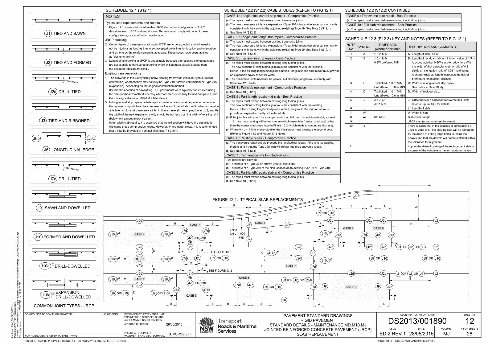
the desirable "design cracking".
are susceptible to transverse cracking which will be more closely spaced than
Longitudinal cracking in JRCP is undesirable because the resulting elongated slabs3.
as "design cracking".
and as long as the reinforcement is adequate. These cases have been labelled
not be injurious as long as they meet accepted guidelines for location and orientation,
Certain types of transverse cracking in JRCP are to be expected and will usually2.
Typical slab replacements and repairs
JRCP cracking
Existing transverse joints
NOTES
No
NOTESYMBOL
(where applicable)
DIMENSIONDESCRIPTION AND COMMENTS
1 A 1.5 m MIN
2 B
0.8W preferred MIN
1.5 m MIN
3 C
Untrafficked: 0.6 m MIN
Trafficked: 1.0 m MIN
See notes to Case Study.
Width of a longitudinal strip repair.C:
4 D
Untrafficked: 0.6 m MIN
Trafficked: 1.0 m MIN Width of residual slab.D:
5 J
J > 1.5 m
J = 0, or
refer to Figure 13.2 for details.
Offset between adjacent transverse tied joint;J:
6 L Length of slabL:
7 W Width of slabW:
8 84° MIN Slab corner angle
9 JRCP slab (or part-slab) replacement
CASE 7 : Termination of a longitudinal joint
premature longitudinal cracking.
A shorter residual length increases the risk of
yields an elongation ratio of 1.25 (maximum).
the width of that particular slab. A ratio of 0.8
is acceptable but 0.8W is preferred, where W is
Length of residual slab. A minimum value of 1.5 mB:
SLAB REPLACEMENT
Length of slab R & RA:
CASE 1 : Longitudinal central strip repair - Compromise Practice
CASE 2 : Longitudinal edge strip repair - Compromise Practice
CASE 3 : Transverse strip repair - Best Practice
CASE 4 : Full-slab replacement - Compromise Practice
CASE 6 : Multiple repair - Compromise Practice
CASE 8 : Part-length repair; slab end - Compromise Practice
CASE 5 : Part-length repair; mid-slab - Best Practice
Schedule 12.3 limits.
The transverse joints need not be parallel but all corner angles must comply with(b)
an expansion cavity of similar width.
Hence, if the existing longitudinal joint is untied, the joint in the strip repair must provide
The new sections of longitudinal joint must be consistent with the existing.
The repair must extend between existing longitudinal joints.(a)
Terminate at a Type J10 at the plan location of an existing Type J9 or Type J10.(b)
Terminate at a Type J7 as shown (that is, mid-slab).(a)
Two options are allowed:
10 #
that a filler be provided of nominal thickness 7 ± 3 mm.
withstand these compressive forces. However, where doubt exists, it is recommended
In full-width slab repairs, it is assumed that the full section will have the capacity to
(below any sawcut and/or sealant).
the width of the new expansion cavity should be not less than the width of existing joint
acts later to close all transverse joints. In these cases (for example, Cases 1, 2, and 6),
the repaired strip will bear the compressive forces of the full slab width when expansion
In longitudinal strip repairs, a full-depth expansion cavity must be provided otherwise5.
the missing slabs were infilled at a later date.)
the "chequerboard" method whereby alternate slabs were fully formed and paved, and
(Before the adoption of sawcutting, JRC pavements were typically constructed using
(expansion), depending on the original construction method.
contraction) whereas they may actually be Type J10 (formed contraction) or Type J16
The drawings in this Set typically show existing transverse joints as Type J9 (sawn4.
See Note 10 (S12.3)(a)
See Note 10 (S12.3)(b)
there is a risk that the Type J2d joint will reflect into the transverse repair.
The transverse repair should precede the longitudinal repair. If the reverse applies,(a)
See Note 10 (S12.3)(b)
The repair must extend between existing longitudinal joints.(a)
the tolerance for alignment.
dowels and that the dowels will not be installed within
by the action of drilling large holes to install the
J10d or J16d joint, the existing slab will be damaged
There is a risk that in the process of constructing a
11
a corner of the concrete in the format dd-mm-yyyy.
Imprint the date of casting of the replacement slab in
The repair must extend between existing longitudinal joints.(a)
The repair must extend between existing longitudinal joints.(a)
CASE 9 : Transverse joint repair - Best Practice
CASE 10 : Full-slab replacement - Best Practice
12
SCHEDULE 12.1 (S12.1)
configurations, or a conforming combination.
describes each JRCP slab repair case. Repairs must comply with one of these
Figure 12.1 shows various allowable JRCP slab repair configurations. S12.21.
SCHEDULE 12.2 (S12.2) CONTINUED
SCHEDULE 12.3 (S12.3) KEY AND NOTES (REFER TO FIG 12.1)
SCHEDULE 12.2 (S12.2) CASE STUDIES (REFER TO FIG 12.1)
See Note 10 (S12.3)(c)
consistent with the cavity in the adjoining (existing) Type J9. See Note 5 (S12.1)
The new transverse joints are expansions (Type J16d) to provide an expansion cavity(b)
The repair must extend between existing transverse joints.(a)
See Note 10 (S12.3)(c)
consistent with the cavity in the adjoining (existing) Type J9. See Note 5 (S12.1)
The new transverse joints are expansions (Type J16d) to provide an expansion cavity(b)
The repair must extend between existing transverse joints.(a)
(Refer to Figure 13.2 and Figure 13.2 Notes)
Where 0 < J < 1.5 m is unavoidable, the initial pour must overlap the second pour.(c)
than the corner cracking shown in Figure 13.2 (which leads to secondary distress).
1.5 m so that cracking will be transverse (which resembles 'design cracking') rather
If the joint layout cannot be arranged such that J=0 then J should preferably exceed(b)
provide an expansion cavity of similar width.
Hence, if the existing longitudinal joint is untied, the joint in the strip repair must
The new sections of longitudinal joint must be consistent with the existing.
The repair must extend between existing longitudinal joints.(a)
PenTable :
PlotDriver :
FilePath :
Printe
d b
y
12:2
1:5
3 P
Mat
28/0
5/2
015
on
PA
V_
BL
AC
K_
GR
EY.tbl
PA
V_P
DF_
modifie
d.pltcfg
O:\Pave
ments\P
1707 - Rigid P
ave
ment
Mainte
nance Sta
ndard Dra
win
gs - J
RC
P\M
D.M
10.M
J_12.d
gn
tetlero
b
SHEET No
No OF SHEETS
© COPYRIGHT ROADS AND MARITIME SERVICESTHIS SHEET MAY BE PREPARED USING COLOUR AND MAY BE INCOMPLETE IF COPIED
FOR AMENDMENTS REFER TO SHEET No 02
A3 ORIGINAL REGISTRATION No OF PLANS
26
ISSUE
ED 2 REV 1 MJ
VOLUME
SCALES: NOT TO SCALE, OR AS NOTED.
DATEJOINTED REINFORCED CONCRETE PAVEMENT (JRCP)
STANDARD DETAILS - MAINTENANCE MD.M10.MJ
RIGID PAVEMENT
PAVEMENT STANDARD DRAWINGS
DS2013/001890ASSET MAINTENANCE DIVISION
ENGINEERING SERVICES BRANCH
PREPARED BY: PAVEMENTS UNIT
APPROVED FOR USE
PAVEMENTS AND GEOTECHNICAL
PRINCIPAL ENGINEER,G. VOROBIEFF
28/05/2015
28/05/2015
TIED AND SAWN
J2 TIED AND FORMED
J6b J6c
J6
J7d
DRILL-TIED
LONGITUDINAL EDGE
DRILL-TIED
DRILL-DOWELLED
J1
J2d
J10d
J3 TIED AND RIBBONED
J9 SAWN AND DOWELLED
J10 FORMED AND DOWELLED
#
J16dDRILL-DOWELLED
EXPANSION:#
COMMON JOINT TYPES - JRCP
CASE 4
CASE 9CASE 8
CASE 10
CASE 6
CASE 5
CASE 5
CASE 2
CASE 1
FIGURE 12.1: TYPICAL SLAB REPLACEMENTS
J10d J10d
J2d
J2d
J2d
J2d
J2d
J2d
J16d J16d
J16d J16d
J9
J1
J2
OR
J7d
J7dJ7d
J7d J7d J7d
J7dJ9 J10
J9
J9 J9
J9
J9
J9
J2
J2
J2
J2
J2
J2
J2
J10 J10 J10
J2d
J2d
J2d
J2d
J2d J2d
J2d J2d
J2d
J7
J7
J7J16d
J10d
J10d
J1
J1
J1
J2
J3
J3
J6
J7d
OR OR
OR
OR
OR
OR OR
D
C
D
D
C
OR
D
C
B
A
J J
J
A
A
AABA
B
B
MIN
1 000MAX
4 300
OR
# #
# #
# #
J10OR J9 J10OR
J7d
J2dOR
J7d J7d
B
J7d
J1
OR
J2 J2dOR
CASE 7
J2d
J7d J7d
CASE 3
#
#
#
OR J2d
J9 J10OR
A
W
L
BABB
SEE FIGURE 13.2
SEE FIGURE 13.2
AB
B

No
NOTESYMBOL
(where applicable)
DIMENSIONDESCRIPTION AND COMMENTS
2 B
0.8W preferred MIN
1.5 m MIN
3 E
4 F
6 L Length of slabL:
7 W Width of slabW:
premature longitudinal cracking.
A shorter residual length increases the risk of
yields an elongation ratio of 1.25 (maximum).
the width of that particular slab. A ratio of 0.8
is acceptable but 0.8W is preferred, where W is
Length of residual slab. A minimum value of 1.5 mB:
CASE 1 : Kerb replacement
CASE 2: Single detector loop; slab-end
CASE 3: Single detector loop; mid-slab
CASE 4: Double detector loop
reconstructed as shown in details K5 to provide adequate shoulder support.
joints as shown, the side of the JRCP slab and abutting kerb should desirably be
Where trapezoidal shaped JRCP slabs develop corner cracks near intersecting J7(a)
SLAB REPLACEMENT - MISCELLANEOUS WORK
6.0 m MAX
4.8 m MIN
1.0 m MAX
0.15 m MIN
length of SFCP patch for a single detector loop.E:
edge distance to detector sawcuts in SFCP.F:
J9 J7d J7d J9
POUR B
J J
POUR A
BAB
Pour B follows Pour A.Scenario 1:
hinge deflections at the transverse joints of Pour A.
The risks are magnified by early trafficking because heavy vehicles will induce
There is a risk of reflection cracking in Pour B (as shown) within days of casting.
Scenario 2: Pour A follows Pour B.
Reflection cracking will not occur if the initial pour overlaps the second pour.
1 A 1.5 m MIN Length of slab R & RA:
5 J
J > 1.5 m
J = 0, or
refer to Figure 13.2 for details.
Offset between adjacent transverse tied joint;J:
CRACKING
REFLECTION
8 JRCP slab (or part-slab) replacement
FIGURE 13.2: MISMATCH OF TRANSVERSE JOINTS
omit tiebars from the longitudinal joint within the overlap length "J".
4-N12 1200 long 200 spacing trimmer bars across the potential crack path, and
Where 0 < J < 1.5 m is unavoidable, provide ancilliary reinforcement in the form of
9 #
10
a corner of the concrete in the format dd-mm-yyyy.
Imprint the date of casting of the replacement slab in
tolerance for alignment.
that the dowels will not be installed within the
action of drilling large holes to install the dowels and
J10d joint, the existing slab will be damaged by the
There is a risk that in the process of constructing a
than corner cracking (which leads to secondary distress).
1.5m so that cracking will be transverse (which resembles "design cracking") rather
If the joint layout cannot be arranged such that J=0 then J should preferably exceed
mesh or bar reinforcement in detector slabs.
Replace existing part-slab with SFCP. Seek specialist advice regarding the use of(a)
mesh or bar reinforcement in detector slabs.
Replace existing part-slab with SFCP. Seek specialist advice regarding the use of(a)
mesh or bar reinforcement in detector slabs.
Replace existing part-slab with SFCP. Seek specialist advice regarding the use of(a)
SCHEDULE 13.1 (S13.1) CASE STUDIES (REFER TO FIGURE 13.1)
(REFER TO FIGURES 13.1 AND 13.2)
SCHEDULE 13.2 (S13.2) KEY AND NOTES
Figure 13.2 Notes:
13
PenTable :
PlotDriver :
FilePath :
Printe
d b
y
12:2
1:5
6 P
Mat
28/0
5/2
015
on
PA
V_
BL
AC
K_
GR
EY.tbl
PA
V_P
DF_
modifie
d.pltcfg
O:\Pave
ments\P
1707 - Rigid P
ave
ment
Mainte
nance Sta
ndard Dra
win
gs - J
RC
P\M
D.M
10.M
J_13.d
gn
tetlero
b
SHEET No
No OF SHEETS
© COPYRIGHT ROADS AND MARITIME SERVICESTHIS SHEET MAY BE PREPARED USING COLOUR AND MAY BE INCOMPLETE IF COPIED
FOR AMENDMENTS REFER TO SHEET No 02
A3 ORIGINAL REGISTRATION No OF PLANS
26
ISSUE
ED 2 REV 1 MJ
VOLUME
SCALES: NOT TO SCALE, OR AS NOTED.
DATEJOINTED REINFORCED CONCRETE PAVEMENT (JRCP)
STANDARD DETAILS - MAINTENANCE MD.M10.MJ
RIGID PAVEMENT
PAVEMENT STANDARD DRAWINGS
DS2013/001890ASSET MAINTENANCE DIVISION
ENGINEERING SERVICES BRANCH
PREPARED BY: PAVEMENTS UNIT
APPROVED FOR USE
PAVEMENTS AND GEOTECHNICAL
PRINCIPAL ENGINEER,G. VOROBIEFF
28/05/2015
28/05/2015
J16dDRILL-DOWELLED
EXPANSION:
TIED AND SAWN
J2 TIED AND FORMED
J6b J6c
J6
J7d
DRILL-TIED
LONGITUDINAL EDGE
DRILL-TIED
J1
J2d
J3 TIED AND RIBBONED
J9 SAWN AND DOWELLED
J10 FORMED AND DOWELLED
HINGE: TIED AND SAWN
COMMON JOINT TYPES - JRCP
DRILL-DOWELLEDJ10d #
J17F
J9
J2
J2
J10
J7
J1 J3
J6
OR OR
OR
J7dCASE 1
CORNER CRACK
1 000 MIN
L
W
J10d J17F
J7d J10d
J2 J2
J9 J10d
DETECTORS
SIGNAL
TRAFFIC
F
FJ2
J2d J2J2
J7d J7d J10
J7d J10
RELIEF EDGE
BEB
F
F
4.5 ± 0.1 m 1.0 ± 0.1 m
CASE 2
CASE 3
CASE 4
KERB LIP LINE
J2d
#
#
#
B E
FIGURE 13.1: MISCELLANEOUS WORK
SEE FIG 13.2
SEE FIG 13.2
B 4.5 ± 0.1 m F

SLAB REPLACEMENT (UNACCEPTABLE PRACTICES)
14
PenTable :
PlotDriver :
FilePath :
Printe
d b
y
12:2
1:5
7 P
Mat
28/0
5/2
015
on
PA
V_
BL
AC
K_
GR
EY.tbl
PA
V_P
DF_
modifie
d.pltcfg
O:\Pave
ments\P
1707 - Rigid P
ave
ment
Mainte
nance Sta
ndard Dra
win
gs - J
RC
P\M
D.M
10.M
J_14.d
gn
tetlero
b
SHEET No
No OF SHEETS
© COPYRIGHT ROADS AND MARITIME SERVICESTHIS SHEET MAY BE PREPARED USING COLOUR AND MAY BE INCOMPLETE IF COPIED
FOR AMENDMENTS REFER TO SHEET No 02
A3 ORIGINAL REGISTRATION No OF PLANS
26
ISSUE
ED 2 REV 1 MJ
VOLUME
SCALES: NOT TO SCALE, OR AS NOTED.
DATEJOINTED REINFORCED CONCRETE PAVEMENT (JRCP)
STANDARD DETAILS - MAINTENANCE MD.M10.MJ
RIGID PAVEMENT
PAVEMENT STANDARD DRAWINGS
DS2013/001890ASSET MAINTENANCE DIVISION
ENGINEERING SERVICES BRANCH
PREPARED BY: PAVEMENTS UNIT
APPROVED FOR USE
PAVEMENTS AND GEOTECHNICAL
PRINCIPAL ENGINEER,G. VOROBIEFF
28/05/2015
28/05/2015
CASE 1: Skewed trench - crossing a transverse contraction joint
corrosion and possibly also to yield failure.
limited benefit. Large crack deflections (and openings) expose the reinforcement to rapid
Because of the high deflections within corner cracks, mesh and/or bar reinforcement provides(b)
Skewed cracking produces acute corners which are then prone to secondary cracking.
The slab cut-out is located in an area of high stress and so creates a risk of corner cracking.(a)
CASE 6: Service pit - slab end
CASE 8: Patch repair - corner or part-width or part-length
Comments under Case 7 also apply.(b)
the residual slab.
A Type J17 joint would increase the risk of block cracking because it would reduce the size of(a)
CASE 9: Service pit - mid slab, circular
case.
distance of the pit from the slab centroid. The design of the isolation joint must cater for the worst
The relative contraction movements between the pit and the slab will increase with increasing(c)
intersections at the pit.
A Type J17 joint is desirable to produce a controlled crack which would reduce the risk of acute(b)
CASE 10: Patch repair or utility- mid slab, rectangular
case.
distance of the pit from the slab centroid. The design of the isolation joint must cater for the worst
The relative contraction movements between the pit and the slab will increase with increasing(b)
risk that the cracking will be skewed.
joint there is an increased risk of longitudinal cracking (resulting in block cracking). There is a high
The cut-out is certain to generate cracking. If the crack runs square to the adjacent longitudinal(a)
CASE 11: Patch repair or utility - edge
CASE 12: Longitudinal trench
CASE 13: Mismatched transverse construction joint
CASE 14: Detector loop sawcutting
to detect the presence of vehicles.
The presence of reinforcing mesh within the slab can significantly reduce the sensitivity of the loop(c)
mechanism, and stress levels vary widely in different zones of the slab.
It is difficult to establish safe limits for sawcut depth because fatigue is a highly variable distress(b)
Sawcuts act as crack initiators, particularly under flexural fatigue loading.(a)
to the slab centroid. The design of the isolation joint must cater for the worst case.
There will be large contraction movements of the slab relative to the pit because of the distance(b)
failure.
deflections (and openings) expose the reinforcement to rapid corrosion and possibly also to yield
Consistent with Case 3, mesh and/or bar reinforcement provides limited benefit. Large crack(a)
CASE 2: Skewed trench - mid-slab
CASE 3: Drainage pit - slab corner
CASE 4: Drainage pit - mid-slab
CASE 5: Service pit - slab corner
with increasing distance of the pit from the slab centroid.
also to yield failure. The relative contraction movements between the pit and the slab will increase
Large crack deflections (and openings) expose the reinforcement to rapid corrosion and possibly
Consistent with Cases 3 and 5, mesh and/or bar reinforcement provides limited benefit.(a)
CASE 7: Patch repair - corner
This is similar to Cases 7 and 8.(a)
(resulting in block cracking). If the crack intersects at a skew then secondary distress is inevitable.
joint then further distress may occur because of the increased risk of longitudinal cracking
The cut-out is certain to generate cracking. If the crack runs square to the adjacent longitudinal(a)
Comments under Case 7 also apply.(b)
are observed.
Trenching will produce elongated slabs which will lead to reduced life unless dimensional limits(a)
"design cracking".
transverse crack which is unlikely to cause distress because it effectively constitutes
A circular pit located within the central third (length-wise) of the slab is likely to generate a single(a)
SCHEDULE 14.1 (S14.1) CONTINUEDSCHEDULE 14.1 (S14.1) CASE STUDIES UNACCEPTABLE PRACTICES
reinstated across the new trench slab, unplanned cracking will result (regardless of reinforcement).
All contraction joints must be continuous between free edges. If the contraction joint is not(b)
This applies both to the residual (original) slabs and to the new trench slab.
Corner angles more acute than 80°-85° are at risk of corner cracking and/or spalling.(a)
This applies to both the original slab and to the replacement slab.
Consistent with Case 1, corner angles more acute than 80°-85° are at risk of corner cracking.(a)
cracking (resulting in block cracking).
However, the existence of two close-spaced parallel cracks increases the risk of longitudinal(b)
distress unless they intersect joints (or cracks) at skew angles less than 80°-85°.
The transverse cracks induced by the pit resemble "design cracking" and so are unlikely to cause(a)
The comments for Case 10 apply.(a)
KERB AND G
UTTER
CASE 14
CASE 12
CASE 10
CASE 11
CASE 13
U
U
U
U
FIGURE 14.1: UNACCEPTABLE WORK PRACTICES
SLAB REPLACEMENT OR UTILITY
CONSEQUENTIAL UNPLANNED CRACKINGTRAFFIC SIGNAL DETECTORS
CRACKING
DESIGN
SCHEMATIC
CRACKING
DESIGN
SCHEMATIC CRACKING
DESIGN
SCHEMATIC
CRACKING
DESIGN
SCHEMATIC
CASE 1
CASE 2
CASE 3
CASE 4
CASE 6
CASE 7
CASE 8
CASE 9
SEE SCHEDULE 14.1 FOR EXPLANATORY NOTES
CASE 5

15
SLAB REPLACEMENT
PenTable :
PlotDriver :
FilePath :
Printe
d b
y
12:2
1:5
8 P
Mat
28/0
5/2
015
on
PA
V_
BL
AC
K_
GR
EY.tbl
PA
V_P
DF_
modifie
d.pltcfg
O:\Pave
ments\P
1707 - Rigid P
ave
ment
Mainte
nance Sta
ndard Dra
win
gs - J
RC
P\M
D.M
10.M
J_15.d
gn
tetlero
b
SHEET No
No OF SHEETS
© COPYRIGHT ROADS AND MARITIME SERVICESTHIS SHEET MAY BE PREPARED USING COLOUR AND MAY BE INCOMPLETE IF COPIED
FOR AMENDMENTS REFER TO SHEET No 02
A3 ORIGINAL REGISTRATION No OF PLANS
26
ISSUE
ED 2 REV 1 MJ
VOLUME
SCALES: NOT TO SCALE, OR AS NOTED.
DATEJOINTED REINFORCED CONCRETE PAVEMENT (JRCP)
STANDARD DETAILS - MAINTENANCE MD.M10.MJ
RIGID PAVEMENT
PAVEMENT STANDARD DRAWINGS
DS2013/001890ASSET MAINTENANCE DIVISION
ENGINEERING SERVICES BRANCH
PREPARED BY: PAVEMENTS UNIT
APPROVED FOR USE
PAVEMENTS AND GEOTECHNICAL
PRINCIPAL ENGINEER,G. VOROBIEFF
28/05/2015
28/05/2015
ACTIVITY METHOD
in the slabs which are to remain.
Every effort must be made to prevent sawcutting slurry from entering joints or cracks5.
removal
Concrete2.
spall the edges of the abutting slabs).
The perimeter strip is then removed manually using jack-picks (taking great care not to(b)
Internal sawcuts are used to break the slab into smaller pieces for removal.(a)
Excavator removal1.
There are two common methods of slab removal:
ACTIVITY METHOD
of tiebars
Reinstatement4.
All other tiebar details must be in accordance with Schedule 7.2.2.
Dowels5.
minimise early stress on the fresh concrete).
At formed joints the dowel length within the second-placed slab must be debonded (to2.
Dowels must be provided in accordance with Schedule 7.2.1.
repairs
Subbase6.
ACTIVITY METHOD
the repair
Cleaning out7.
debonding
Subbase8.
and sealing
debonding
Joint9. 1.
2.
Reinforcement
10.
design
11. Concrete mix
13. Jointing
traffic
14. Opening to
joint faces
of exposed
Preparation3.Sawcutting1.
line), in which case it may be a butt joint.
located 0.5 m or more outside a trafficked lane (for example ≥ 0.5 m outside an edge
All other longitudinal joints must be corrugated, keyed, or scabbled unless the joint is(b)
dowelled joints●
any untied joint●
The following joints may be butt joints:(a)
Longitudinal joints2.
removal with a minimum of damage to adjacent slabs / joints and to the subbase.
Internal cuts within the slab to break it in to manageable pieces to facilitate(b)
correct defects in the joints or adjacent slabs.●
reduce the risk of edge and arris damage on the slabs which are to remain.●
assist in slab removal.●
Perimeter cuts along existing joints (or with a minor offset) to:(a)
Two types of sawcuts are typically required:1.
Faces
Joints and cracks
strength development needed to suit trafficking requirements.(c)
construction logistics.(b)
structural and thickness design requirements.(a)
The concrete mix must be designed with consideration of:1.
not extend beyond the limits of removal.
longitudinal joint must not extend beyond the limits of removal. Transverse sawcuts must
250 mm beyond the limits of removal. Longitudinal sawcuts which are offset from an existing
Longitudinal sawcuts which precisely follow an existing longitudinal joint may extend up to4.
(S15.1): CONTINUED
arris rounding may require treatment in accordance with Figure 25.1.
In addition to those defects listed in Schedule 16.1 (and related Detail drawings) minor(e)
material.
and re-entrant angles. Minor defects may be corrected by plastering with an appropriate
The exposed face must be dense and fully compacted, and be free of honeycombing(d)
additional spalling).
itself may be best deferred until after the slab R & R (because the R & R may cause
be easier if carried out before removal of the failed slab. However, the defect repair
Where remedial sawing is required (to correct defects in adjoining joint faces), it may(c)
Spall repairs must be completed in accordance with MJ24 and MJ25.
be placed integrally with the adjoining concrete).
independently of the placement of adjoining concrete (that is, the repair material must not
Where remedial treatment (such as spall repair) is needed, it must be completed(b)
Exposed faces must be assessed and treated in accordance with Schedule 16.1.(a)
General1.
to the form to minimise edge damage during recovery.
first-placed slab for later straightening before the second pour. They need be placed close
single-lane R & R, tiebar drilling can be avoided by placing L-shaped tiebars into the
Where two adjoining slabs (joined by a common longitudinal joint) are to be replaced by3.
SCHEDULE 15.1 (S15.1): FULL AND PART-SLAB R & R (S15.1): CONTINUED
cleaned and then treated with a debonding agent in accordance with Schedule 7.1.
Before the replacement base is placed, the full face of all joints must be thoroughly
uneven bedding under the adjacent slab when the direction of curling reverses).
with a silicone sealant where it exceeds about 0.5 mm. (Ingress of grout will create
The exposed horizontal gap between the subbase and the base should also be sealed(b)
a silicone sealant to prevent ingress of mortar.
All corners, joints and any underlying cracks in the exposed slabs must be sealed with(a)
Mesh must be placed to provide cover as specified in Note 7 Schedule 7.1.2.
Replacement slabs must be reinforced with mesh as shown in Table 10.1.1.
new concrete
12. Placing of
New joints must be designed and constructed in accordance with MJ05-MJ09.
of these cylinders will provide the best guidance for timing of access to the repair area.
should be cast and cured alongside the slab and in a similar manner. Progressive testing
In order to monitor the rate of strength gain actually achieved on site, additional cylinders2.
materials and work processes may be used for guidance.
In cases where the requirements of Note 14.2 are not practicable, experience with particular3.
Note:
(a)
to trafficking strength.
Notes in this Schedule are referred to by both Activity and Method number. For example, Note 14.1 relates
8 m long, 4 m wide, 230 mm thick JRCP slabs typically have a mass of 18 t.●
Skewing of the slab often jams it in place and damages adjoining edges and arrisses.●
Subbase bond/suction can exceed 50 t per slab (for an 8 m long x 4 m wide slab);●
This method can be difficult because:(d)
The perimeter strip is then removed manually, in accordance with Note 2.1.(c)
using chemical anchors. They must be designed by a Chartered Professional Engineer.
The lifting hooks should be eye bolts which are resin-grouted into the top of the slab(b)
The slab (within the full-depth cuts) is lifted in a single piece.(a)
Crane lift2.
with Schedule 16.1.
the face will be smooth as a result of sawing and hence must be treated in accordance
All other transverse joints must be corrugated, keyed, or scabbled. In many cases,(b)
dowelled joints●
any untied joint●
The following joints may be butt joints:(a)
Transverse joints3.
design spacings in accordance with Table 9.1.longitudinal joints:●
at 500 c/ctransverse construction joints:●
must be as follows:
Drill-ties must be provided to replace or supplement existing tiebars. The final tiebar spacing1.
high interlayer bonding, which may initiate unplanned base cracking.(b)
reflection of subbase cracks into the new base.(a)
widths. The major risks associated with such defects are:
Cracks in the subbase should be examined for spalls, stepping, and for excessive crack2.
Seek specialist advice for assessment and repair of subbase.1.
200 mm from joints, but may be varied to suit individual conditions.
If existing tiebars are to be replaced by drill-ties, sawcuts would typically be about(b)
for welded splices.
and 400 mm for N16 bars. Shorter lengths are allowed (in accordance with AS3600)
To save tiebars, sawcuts must be located to provide lap lengths of 300 mm for N12 bars(a)
or cut.
a concrete subbase. Their location will depend on whether existing tiebars are to be saved
Internal cuts are typically just less than full-depth, but should not be deep enough to touch2.
minor corrections) rather than replacing them with a scabbled face.
Where existing corrugations are conforming, it is preferable to retain them (perhaps with
whether the existing corrugations or keyways are to be saved; see also Activity 3.(c)
rounding).
whether defects in the exposed face need to be corrected (for example spalling and/or(b)
whether tiebars are to be saved or cut.(a)
joint needs consideration. Factors include:
Perimeter cuts may be either full-depth or part-depth, and their precise location relative to the3.
All waste material resulting from the above operations must be removed.
compressive strength of 20 MPa.
The pavement should not be opened to traffic until the concrete has attained insitu1.
sheeting on the subbase in accordance with M258.
vehicles. An alternative method of debonding the subbase and base is to place polyethylene
A cover aggregate may be warranted to facilitate access by workers and construction
For granular subbases (including rolled concrete), a bitumen emulsion must be used.
The typical debonding treatment on LCS is wax emulsion applied at a rate of 0.5 litre/m².
Debonding must conform with M258.2.
very low friction can result in poor induction of joints.●
strong bonding may initiate unplanned base cracking.●
layers, for the following reasons:
It is important to achieve a suitable level of debonding between the subbase and base1.
● protection● curing● texturing● compaction● paving
cover issues such as:
Placing of concrete must also accord with the principles detailed in NR82 and NR83, which2.
Work must be in accordance with M258.1.

16
SLAB REPLACEMENT
PenTable :
PlotDriver :
FilePath :
Printe
d b
y
12:2
2:0
0 P
Mat
28/0
5/2
015
on
PA
V_
BL
AC
K_
GR
EY.tbl
PA
V_P
DF_
modifie
d.pltcfg
O:\Pave
ments\P
1707 - Rigid P
ave
ment
Mainte
nance Sta
ndard Dra
win
gs - J
RC
P\M
D.M
10.M
J_16.d
gn
tetlero
b
SHEET No
No OF SHEETS
© COPYRIGHT ROADS AND MARITIME SERVICESTHIS SHEET MAY BE PREPARED USING COLOUR AND MAY BE INCOMPLETE IF COPIED
FOR AMENDMENTS REFER TO SHEET No 02
A3 ORIGINAL REGISTRATION No OF PLANS
26
ISSUE
ED 2 REV 1 MJ
VOLUME
SCALES: NOT TO SCALE, OR AS NOTED.
DATEJOINTED REINFORCED CONCRETE PAVEMENT (JRCP)
STANDARD DETAILS - MAINTENANCE MD.M10.MJ
RIGID PAVEMENT
PAVEMENT STANDARD DRAWINGS
DS2013/001890ASSET MAINTENANCE DIVISION
ENGINEERING SERVICES BRANCH
PREPARED BY: PAVEMENTS UNIT
APPROVED FOR USE
PAVEMENTS AND GEOTECHNICAL
PRINCIPAL ENGINEER,G. VOROBIEFF
28/05/2015
28/05/2015
FIGURE 16.2: CORRUGATED JOINTS
which were common in NSW until the mid-1980s.
This shows typical dimensions for keyed joints,(a)
superseded in the mid-1980s by corrugated faces.)
successfully. (For these reasons, they were
(as shown) and were very difficult to slipform
They were susceptible to failure of the concave arris(b)
surface mortar.
be in the first-placed slab, which can be identified by
assume, following from (c), that the concave side will
in the absence of clear evidence), it is reasonable to
In trying to identify the orientation of the keyway (and(d)
with Figure 17.1.
otherwise), scabble the face in accordance
If the key is totally removed (by mistake, or(c)
with Figure 17.1.
otherwise), scabble the face in accordance
If the key is totally removed (by mistake, or(c)
material removed from the exposed faces.
the resulting face after treatment.
cracking in the new slab.
Scabble to remove any lip which might cause
1
MIN
3
attaching extra moulds to the form).
it is also easier to construct in this orientation (by
stress from the adjoining slab. In fixed-form paving,
so that it gains strength before being subjected to
typically require that the concave side be placed first,
concrete shear strength is low. Hence, specifications
can occur within days of construction while the
by load deflections and slab curling. Microcracking
side to the high arris stresses which are generated
The concave side is more sensitive than the convex(c)
25 60
30TIEBAR
15 ± 5NEW SLAB
15 ± 5NEW SLAB
NEW SLAB
D/3 TYP
CRACK
INDUCED
REMOVE LIP
NEW SLAB
VERTICAL FACE 45 MIN
NEW SLAB
VERTICAL FACE 45 MIN
POTENTIAL SPALL
SCABBLE
EXISTING JOINT RECESS
FIGURE 16.1:
16.1 AND 16.2
KEY TO FIGURES
(a)TYPE
JOINT
EXPOSED
DESCRIPTION NOTES
The joint effectively converts to a Type J2, scabbled.(b)
in the new slab.
Remove any lip to minimise the risk of crack initiation(a)
Refer to Figure 16.1.
corrugated
J2
J2, keyedRefer to Figure 16.3.
Refer to Figure 17.1.J2, butt
J3
J4
New tied joints
New untied joints
Design a sealant in accordance with Table 8.1.(f)
Carry out spall repairs in accordance with MJ24 and MJ25.(e)
and so do not need to be scabbled.
Untied joints are not expected to transfer shear loads(d)
sawn
J5,
ribboned
J5
J6
for remedial treatments on rounded/spalled edges.
according to the new joint type. See MJ24 and MJ25
Where widening is required at a Type J6, treat the edge
corrugated
J7
tied
construction:
Transverse
J7, keyed
Refer to Figure 16.3.
tied
construction:
Transverse
Refer to Figure 17.1.
tied
construction:
Transverse
J7, butt
where a spall repair has been carried out.
to minimise the stress on the abutting arrises, particularly
(sealed) joint cavity may be desirable in some situations
Formed tied joints normally do not require sealing, but a(b)
Treat in accordance with Cases 2-7.(a)
Refer to Figure 17.2.
tied and sawn
Longitudinal:
tied and formed
Longitudinal:
tied and formed
Longitudinal:
tied and formed
Longitudinal:
The alternatives are as follows.
will depend on whether the new joint will be tied or untied.
Where an existing J4 face is exposed, the required treatment
ribboned
untied and
Longitudinal:
edge
Longitudinal:
OF JOINTS EXPOSED DURING R & R
SCHEDULE 16.1 (S16.1): TREATMENT
Design a sealant in accordance with MJ08.(b)
Treat in accordance with Cases 2-7.(a)
Refer to Figure 17.2.
ribboned
tied and
Longitudinal:
sawn
untied and
Longitudinal:
FIGURE 16.3: KEYED JOINTS
Case 2: Exposed convex face
Case 2: Exposed convex face
J1
J8
sawn
construction:
Transverse Not valid.
J9
J10
J11
J12
J13
J14
Design a filler and sealant in accordance with MJ08.(c)
Carry out spall repairs in accordance with MJ24 and MJ25.(b)
Scabbling is not required.(a)
J15
J16
J17
The joint effectively converts to a Type J2, scabbled.(b)
initiation in the new slab.
Remove any lip (by scabbling) to minimise the risk of crack(a)
Refer to Figure 16.1.
J18 according to the new joint type.
Where widening is required at a Type J18, treat the edge
gains its design strength.)
with the new concrete will cause distress before the patch
the embedded length is also debonded because any bond
Debond all exposed dowels. (This applies even where(d)
Design a sealant in accordance with MJ08.(c)
Carry out spall repairs in accordance with MJ24 and MJ25.(b)
Untied joints do not need to be scabbled.(a)
gains its design strength.)
the new concrete will cause distress before the patch
embedded length is also debonded because any bond with
Debond all exposed dowels. (This applies even where the(d)
Design a sealant in accordance with MJ08.(c)
Carry out spall repairs in accordance with MJ24 and MJ25.(b)
Untied joints do not need to be scabbled.(a)
dowelled
sawn and
contraction:
Transverse
dowelled
formed and
contraction:
Transverse
knifed
contraction:
Transverse
dowelled
knifed and
contraction:
Transverse
formed
contraction:
Transverse
beam
with subgrade
Isolation:
beam
subgrade
without
Isolation:
dowelled
Expansion:
tied and sawn
Hinge:
(S16.1): CONTINUED
DESCRIPTION
TYPE
JOINT
EXPOSED
(a)NOTES
joint type.
Treatments are based on the joint types encountered in the field, not the intended
Not valid.
Not valid.
of the convex side.
is warranted in conjunction with replacement
than about 45 mm) and so preventive work
(particularly if the top vertical face is less
side remains at risk of future failure
However, the top section on the concave
carry the same risk as with the concave slab.
Replacement of the convex slab does not(a)
(a)
SAWCUT
SAWCUT
SAWCUTSAWCUT
scabbling, after removal of the failed slab.(ii)
to assist with the slab removal), or
(as shown above, possibly arranged
sawcutting before slab removal(i)
This could be done by:
to 15 mm ± 5.
arris, the convex key should be reduced
To minimise stresses on the new concave(b)
minimum vertical face dimension.
Sawcut (if necessary) to provide the specified
spall repairs.
lengths. They are also beneficial to minimise stresses on
should be sealed to maintain consistency with adjacent joint
Formed tied joints normally do not require sealing, but they
Design a sealant in accordance with Table 8.2.(c)
MJ24 and MJ25.
Carry out any spall repairs in accordance with(b)
scabbling in accordance with Schedule 15.1 Activity 3.
If the exposed face is smooth, assess the warrant for(a)
Design a sealant in accordance with MJ08.(b)
MJ24 and MJ25.
Carry out any spall repairs in accordance with(a)
Shading indicates the following:
provided on MJ05-MJ09.
corrugations if they depart substantially from the advice
Further remedial treatment may be required on the underlying
Refer to Figure 16.2.
formed
untied and
Longitudinal:
Treat in accordance with Type J10.
Treat in accordance with Type J14.
Design a filler and sealant in accordance with MJ08.(b)
Treat in accordance with Type J10.(a)
Note:
D/3+10 from the top (as shown in Figure 17.1).
Scabble the sawn section which is more than
Sawcut to the bottom of the top corrugation.
Option 2:
prevent future spalling on the concave side).
the specified minimum vertical face (to
Sawcut and scabble as shown to provide
Option 1:
FAILURE MODE
COMMON
Case 1: Typical keyed joint
Case 1: Exposed concave face
Case 3: Exposed concave face
replacing or repairing keyed slabs.
hence special care is warranted when
could also occur in replacement slabs,
The type of failure described under Case 1(a)
assist in slab removal.(ii)
and/or
remove arris spalling (or rounding),(i)
desirable in order to:
The sawcut (as shown) may also be(b)
provided in Table 10.2.
corrugations if they depart substantially from the advice
Further remedial treatment may be required on the underlying
Refer to Figure 16.2.
beamed
edge and
Longitudinal:

17
SLAB REPLACEMENT
PenTable :
PlotDriver :
FilePath :
Printe
d b
y
12:2
2:0
1 P
Mat
28/0
5/2
015
on
PA
V_
BL
AC
K_
GR
EY.tbl
PA
V_P
DF_
modifie
d.pltcfg
O:\Pave
ments\P
1707 - Rigid P
ave
ment
Mainte
nance Sta
ndard Dra
win
gs - J
RC
P\M
D.M
10.M
J_17.d
gn
tetlero
b
SHEET No
No OF SHEETS
© COPYRIGHT ROADS AND MARITIME SERVICESTHIS SHEET MAY BE PREPARED USING COLOUR AND MAY BE INCOMPLETE IF COPIED
FOR AMENDMENTS REFER TO SHEET No 02
A3 ORIGINAL REGISTRATION No OF PLANS
26
ISSUE
ED 2 REV 1 MJ
VOLUME
SCALES: NOT TO SCALE, OR AS NOTED.
DATEJOINTED REINFORCED CONCRETE PAVEMENT (JRCP)
STANDARD DETAILS - MAINTENANCE MD.M10.MJ
RIGID PAVEMENT
PAVEMENT STANDARD DRAWINGS
DS2013/001890ASSET MAINTENANCE DIVISION
ENGINEERING SERVICES BRANCH
PREPARED BY: PAVEMENTS UNIT
APPROVED FOR USE
PAVEMENTS AND GEOTECHNICAL
PRINCIPAL ENGINEER,G. VOROBIEFF
28/05/2015
28/05/2015
Sawcut and scabble.
Option 1:
vertical face dimension.
Locate the sawcut to achieve the required
on the underlying face.
vertical face dimension, and the limiting slope
Locate the sawcut to achieve the required
Sawcut and scabble.
Option 1:
MJ24 and MJ25.
Carry out a spall repair as shown on
Option 2:
MIN
3
NEW SLAB
VERTICAL FACE 45 MIN
POTENTIAL SPALL
RIBBON
VERTICAL FACE
SCABBLE TO NEAR
NEW SLAB
RIBBON
FOR REMOVAL
SECTION
SCABBLE
NEW SLAB NEW SLAB NEW SLAB
VERTICAL FACE 45 MIN VERTICAL FACE 45 MIN VERTICAL FACE 45 MIN
OPTION 1 OPTION 2
CONCAVE ARRIS
REMOVE
RIBBON
CONCAVE ARRIS
REMOVE
MIN
3
1
RIBBONRIBBON
1
MIN
3
FOR REMOVAL
SECTIONREPAIR
SPALL
RIBBON
FACES
SCABBLED
INDUCED CRACK
RIBBON
sawing for joint resealing.
Frequent lateral deflections will complicate future
(which are likely to initiate unplanned cracking).
nonconforming because they create joint mismatches
plan alignment of the joint. Stepped offsets are
Consideration also needs to be given to the resulting(e)
length may be impractical over longer lengths.
A technique which is suitable for an isolated short
according to the length of nonconformity.
The selected method of repair is likely to vary(d)
accordance with Cases 2-7.
Where the ribbon is curled and/or inclined, treat in(c)
(apart from debonding) before concrete placement.
will leave a face which requires little or no treatment
Where the ribbon was well installed, joint exposure(b)
curled and/or inclined.
variable and they will often be found deeper and/or
shown here. However, their accuracy was highly
Specifications required that ribbons be placed as(a)
MJ24 and MJ25.
Carry out a spall repair as shown on
Option 2:
PERIMETER GROOVE 15
= 90° ± 5°
D/3
010
+ –
NEW SLAB
FIGURE 17.2: RIBBONED JOINTS
Case 1: Model ribboned joint Case 2: Curled and vertical Case 3: Curled and inclined
Case 5: Curled and vertical Case 6: Curled and inclined Case 7: Curled and inclined
SAWCUTSAWCUT
SAWCUTSAWCUT
SAWCUT
SAWCUT
D
D/3+10 MAX45 MINNEW SLAB
25 ± 15
SCABBLED FACE
FIGURE 17.1: BUTT AND SCABBLED FACES
than 1 in 3.
underlying face at a slope not greater
minimum) and the need to transition the
the vertical face dimension (of 45 mm
The location of the sawcut is dictated by(a)
material removed from the exposed faces.
the resulting face after treatment.
Shading indicates the following:3.
Where the new joint will be tied, a sealant will not be required in most cases. Where the new joint will be untied, a sealant must be designed in accordance with MJ08.2.
Ribboned joints are no longer used for new construction or maintenance work.1.
The face must be debonded in accordance with Activity 9 (S15.1).(d)
the new slab.
surface with indentations 4-6 mm deep that will provide a key for
over a large proportion of the scabbled face and to achieve a rough
Scabbling must be thorough enough to expose coarse aggregate(c)
damage from scabbling and to minimise arris spalling.
The top and bottom sections must be left smooth to prevent(b)
The warrant for scabbling is detailed under Activity 3 (S15.1).(a)
Figure 17.2 Notes:
from the top (as shown in Figure 17.1).
be scabbled below the line D/3+10 mm
Where deep sawing is used, the face must(b)
sawing and scabbling, or by deeper sawing.
Remove the ribbon by a combination of(a)
sawcut
1 ± 1
1
VERTICAL FACE 45 MIN
1
MIN
3
OPTION 1 OPTION 2
NEW SLAB
VERTICAL FACE 45 MIN
RIBBON
SCABBLE
NEW SLAB
RIBBON
REPAIR
SPALL
FACES
SCABBLED
PERIMETER GROOVE 15
Case 4: Curled and inclined
SAWCUT
SAWCUT

18
CROSS STITCHING OF CRACKS AND JOINTS - COMPROMISE PRACTICE
PenTable :
PlotDriver :
FilePath :
Printe
d b
y
12:2
2:0
3 P
Mat
28/0
5/2
015
on
PA
V_
BL
AC
K_
GR
EY.tbl
PA
V_P
DF_
modifie
d.pltcfg
O:\Pave
ments\P
1707 - Rigid P
ave
ment
Mainte
nance Sta
ndard Dra
win
gs - J
RC
P\M
D.M
10.M
J_18.d
gn
tetlero
b
SHEET No
No OF SHEETS
© COPYRIGHT ROADS AND MARITIME SERVICESTHIS SHEET MAY BE PREPARED USING COLOUR AND MAY BE INCOMPLETE IF COPIED
FOR AMENDMENTS REFER TO SHEET No 02
A3 ORIGINAL REGISTRATION No OF PLANS
26
ISSUE
ED 2 REV 1 MJ
VOLUME
SCALES: NOT TO SCALE, OR AS NOTED.
DATEJOINTED REINFORCED CONCRETE PAVEMENT (JRCP)
STANDARD DETAILS - MAINTENANCE MD.M10.MJ
RIGID PAVEMENT
PAVEMENT STANDARD DRAWINGS
DS2013/001890ASSET MAINTENANCE DIVISION
ENGINEERING SERVICES BRANCH
PREPARED BY: PAVEMENTS UNIT
APPROVED FOR USE
PAVEMENTS AND GEOTECHNICAL
PRINCIPAL ENGINEER,G. VOROBIEFF
28/05/2015
28/05/2015
TABLE 18.2: STITCHING LENGTHS
FIGURE 18.2: STITCH-BAR PROTECTION
CASE 12
SCHEDULE 18.2 (S18.2)
SCHEDULE 18.1 (S18.1)
Table 18.2 Notes:
TRANSVERSE AND CORNER CRACKS
STITCH-BAR SPACINGS FOR
TABLE 18.4:
A A
NOT TO SCALE
p
b/2
SUBBASE
L
==
L
t
D
t
L
L
FIXING COMPOUND
h
b
c
NOTES
L (mm)
hole to crack
Offset: drill
215
210
200
190
180
175
165
(mm)
D
Base thickness
c
250
240
230
220
210
200
190
250
300
Corner cracks 300
500Transverse cracks
L (mm)
protection
Length of
pL (mm)
stitch-bar
Length of
L (mm)
hole
Length of drill
bh
400450
380430
360410
340390
320370
300350
280330
CASE 10 : Longitudinal tied joint
CASE 9 : Late sawcut cracking
CASE 8 : Late sawcut cracking
CASE 7 : End-slab transverse cracking
CASE 6 : Multiple cracking
CASE 5 : Small corner cracks
CASE 4 : Large corner cracks
CASE 3 : Transverse mid-slab cracking
CASE 2 : Skewed longitudinal cracking
CASE 12 : Anchor Slabs
CASE 11 : Kerbs
CASE 1 : Longitudinal cracking
1
5
7
Not suitable for stitching. Similar to Case 8.(a)
success because secondary cracking is likely.
In unreinforced anchor slabs (that is, superseded design) stitching has had only moderate(b)
Stitching is not required or warranted in reinforced anchor slabs.(a)
See Fig 18.2 for protection details(b)
To suit drill angle = 30° and cover t = 25 mm(a)
Table 18.3 Notes:
(a,b)
7.1 - 7.5
(mm)
A
Joint offset
260240220200180
> 8
7.6 - 8.0
6.6 - 7.0
6.1 - 6.5
5.6 - 6.0
5.1 - 5.5
4.6 - 5.0
4.1 - 4.5
3.6 - 4.0
3.1 - 3.5
< 3.1
RED (m)
distance
edge
Relief-
(c) Base thickness D (mm)
MIN
300 mm
but
½C (± 200)
280
These dimensions apply for all slab sizes.1.
MAX
Spacing B (mm)
(TYP AND MIN)
Joint offset A (mm)
METHOD
L
CAPPING
FIGURE 18.1: TYPICAL CROSS-STITCHING APPLICATIONS
Spacing C (mm)
Check the total tied width.(i)
DENOTES RELIEF-EDGE DISTANCE*
BASE
*RED
KE
RB (
TIE
D)
J6
J1
J2
J3
OR
OR
J1
J2
J3
OR
OR
J6
J9
J2
J9 J10OR
BA
d1
CASE 1
CA
CASE 2C
A
*
d4
B
4
CASE 4
CASE 5
RED*
AC
d
d
5
5
CASE 3
CASE 6
dd
33
BBA A
d7
CA
CASE 7
CASE 10
CASE 8
RED*
CASE 11
CASE 9
LONGITUDINAL CRACKS AND JOINTS
STITCH-BAR SPACINGS FOR
TABLE 18.3:
ANCHOR
Cracking could be due to an inactive shoulder joint which may need sawing and/or deepening.(c)
Success is improved for d greater than 1 m.(b)
May be suitable for stitching.(a)
Secondary corner cracking is likely if β is less than 70°.(b)
a slab edge.
May be suitable for stitching if completed before the crack reaches another longitudinal joint or(a)
3
Do not stitch joints which are intended to be untied.(b)
May be suitable for stitching (to supplement tiebars).(a)
For convenience, insert all stitch-bars from the pavement side.(b)
May be suitable for stitching.(a)
400450450500600
400
450
450
500
500
600
700
700
900
400
450
500
500
600
600
700
700
900
450
500
500
600
600
700
700
900
1200
500
500
600
600
700
700
900
1200
500
600
600
700
700
900
1200
1200
400
400
450
450
450
500
600
600
700
900
900 900 900
900 900
900 900
900
Cross stitching may only be used with the written approval of the Principal.2.
weather (or during the middle of the day) when the crack is most tightly closed.
For the same reason, stitch-bars are best fixed (that is, epoxied) during warmer
avoid the need for routing and sealing.(d)
keep out incompressibles and water, hence:(c)
significantly reduce the chances of secondary slab cracking;(b)
maximise load transfer between slabs, hence:(a)
before they widen. Early stitching will:
formation of the crack, before it widens. Poorly tied joints should also be stitched
Crack stitching will be most successful if it is completed very soon after5.
RED
A
TABLE 18.1: STITCHING NOTES
are necessary.
service life of a slab before more extensive repairs such as slab replacement
Cross Stitching Compromise Practice is a technique which may extend the1.
routed. See Note 2 S12.1.
opening (that is, are stable) should not be stitched and may also not need to be
corroded mesh reinforcement or tiebars (as applicable). Cracks that are not
cracks/tied joints open up beyond 0.5 mm, due to causes such as inadequate or
Cross stitching of JRCP cracks or tied joints is only needed where the3.
previous success under similar conditions.(c)
intensity of heavy vehicle traffic.(b)
such as arris spalling, surface abrasion, condition of adjacent slabs).
the quality of the concrete (as indicated by distress additional to cracking,(a)
should take into consideration factors such as:
The decision to stitch (in preference to alternatives such as slab replacement)6.
thickness of 0.2 to 0.5 mm.
than 0.5 mm. Suitable protection is provided by bituminous paint with a
Protection must be provided in accordance with Figure 18.2 if the crack is wider7.
and joints only.
Use compressible self expanding polyurethane resin (foam) to seal wider cracks8.
It must include tied kerbs.
or crack being stitched to the nearest relief edge.
Relief-edge distance (RED) is measured from the joint(c)
Spacings may be varied by ±10% to suit site conditions.(b)
the underside of base and on the use of N12 stitch-bars.
This table is based on a coefficient of friction of 1.5 at(a)
N12 DEFORMED BAR
STITCH-BAR
SEE NOTE 7 (S18.1)
See Note 2 S12.1.(c)
Success is improved for d greater than 1.5 m.(b)
May be suitable for stitching.(a)
4
4For d less than 0.6 m (approximately), refer to Case 5.(c)
could indicate low strength concrete.
Success is reduced if other distress such as advanced arris spalling is present because this(b)
May be suitable for stitching where d is greater than 0.6 m and concrete is sound.(a)
Not suitable for stitching. Ongoing deterioration is likely.(a)
Treat According to Case 9 shown on MJ12 (or Case 8 if approved).(c)
This crack is effectively operating as the contraction joint and so stitching would lock up the joint.(b)
Not suitable for stitching.(a)
9 shown on MJ12 (or Case 8 if approved).
Not suitable for stitching where d is less than 0.6 m (approximately). Treat according to Case(a)
secondary cracking. Treat according to Case 9 shown on MJ12 (or Case 8 if approved).
Not suitable for stitching where d is less than 1.0 m (approximately) because of the risk of(a)
Table 18.4 Note:
After the capping material has set, open to traffic.11.
If the capping material is different from the resin, top off with the capping material after the resin has set.10.
to approximately 25 mm below the surface.b)
to the surface if the resin is the capping material, ora)
Inject further resin if required:9.
Insert the stitch-bar while gently oscillating the bar. Push the bar to the required depth.8.
Inject the resin/epoxy to the manufacturer's instructions to fill approximately 1/3 depth of the hole.7.
Thoroughly clean holes using a vacuum cleaner.6.
16 mm diameter drill bit and ensure that a clean concrete face results.
Where sealing has been undertaken, ream the hole after the self expanding resin (foam) has set using a5.
(foam) to prevent escape of the epoxy.
Where the crack width exceeds 1 to 2 mm, seal it (at the level of the stitch-bar) with self expanding resin4.
diameter must be less than the final hole diameter of 16 mm.
Drill holes (drill hole vertically for the first 10 mm to start). If crack sealing is required, the initial hole3.
Mark hole locations.2.
Investigate base thickness, determine the required length of stitch-bar, and offset of drill holes.1.
where base thickness is less than 180 mm.(c)
the concrete has low strength (less than 25 MPa), or(b)
the slab has two or more cracks, or(a)
Stitching is unlikely to be effective where:4.β
d
A
CA

19
JOINT RESEALING
PenTable :
PlotDriver :
FilePath :
Printe
d b
y
12:2
2:0
5 P
Mat
28/0
5/2
015
on
PA
V_
BL
AC
K_
GR
EY.tbl
PA
V_P
DF_
modifie
d.pltcfg
O:\Pave
ments\P
1707 - Rigid P
ave
ment
Mainte
nance Sta
ndard Dra
win
gs - J
RC
P\M
D.M
10.M
J_19.d
gn
tetlero
b
SHEET No
No OF SHEETS
© COPYRIGHT ROADS AND MARITIME SERVICESTHIS SHEET MAY BE PREPARED USING COLOUR AND MAY BE INCOMPLETE IF COPIED
FOR AMENDMENTS REFER TO SHEET No 02
A3 ORIGINAL REGISTRATION No OF PLANS
26
ISSUE
ED 2 REV 1 MJ
VOLUME
SCALES: NOT TO SCALE, OR AS NOTED.
DATEJOINTED REINFORCED CONCRETE PAVEMENT (JRCP)
STANDARD DETAILS - MAINTENANCE MD.M10.MJ
RIGID PAVEMENT
PAVEMENT STANDARD DRAWINGS
DS2013/001890ASSET MAINTENANCE DIVISION
ENGINEERING SERVICES BRANCH
PREPARED BY: PAVEMENTS UNIT
APPROVED FOR USE
PAVEMENTS AND GEOTECHNICAL
PRINCIPAL ENGINEER,G. VOROBIEFF
28/05/2015
28/05/2015
D
W
D
R
e
J
S
D
1
e
e(e)
JS
D
(g)
(c)S
(b)
6
6.0
4.8
4.4
4.0
3.5
2.9
74
2.1
32 5
slabs
Bridge approach25 ± 4 14 (+ 4,- 0) 10 ± 4 12 ± 4 50 ± 5
longitudinal
> 18
13.0 < L ≤ 15.0
11.5 < L ≤ 13.0
9.5 < L ≤ 11.5
8.0 < L ≤ 9.5
6.5 < L ≤ 8.0
4.6 < L ≤ 6.5
≤ 4.6 7 (+ 3,- 0)
9 (+ 3,- 0)
10 (+ 3,- 0)
11 (+ 3,- 0)
12 (+ 4,- 0)
14 (+ 4,- 0)
17 (+ 5,- 0)
7 (+ 3,- 0)
8 (+ 3,- 0)
8 (+ 3,- 0)
9 (+ 3,- 0)
10 (+ 4,- 0)
11 (+ 4,- 0)
14 (+ 4,- 0)
O (mm)
Opening
Design Joint
SW' (mm)
Width
D' (mm)
Depth
(etc)
Contractions
(f) (f)expansions
Isolations and
D' (mm)
depth
Joint
Width (W ) (m)
or
Slab Length (L )
Table 19.1 Notes:
e
METHOD
DESIGNNOTES
SCHEDULE 19.1 (S19.1) SCHEDULE 19.2 (S19.2)
SCHEDULE 19.3 (S19.3)
S
e e
S
S
S
S
FIGURE 19.2: JOINT DIMENSIONS
W'
R'
D'
D'
ORIGINAL JOINT
RESAWN JOINT
S
SS
J
SS
J
S
AN
D M
IN
10 N
OM
AN
D M
IN
10 N
OM
Recess R' (mm)
silicone sealant width.
See Table 8.3 Note (a) regarding maximum desirable
SEALANT
SILICONE
SEALANT
SILICONE
J6
J6
J4
J5
J10
J10
J14
J10
J10
J12
J16
J9
J7
J9
J9
J1
J2
J3
OR
OR
J2
OR
J6
J2
J6J2
J2
KE
RB (
TIE
D)
SEE FIG 21.1
SEE FIG 21.2
SEE FIG 20.1
SEE FIG 20.4
SEE FIG 21.3
SEE FIG 21.2
SEE FIG 21.3
FIGURE 19.1: TYPICAL JOINT RESEALING APPLICATIONS
BACKER ROD
POLYETHYLENE
CLOSED-CELL
BACKER ROD
POLYETHYLENE
CLOSED-CELL
In Table 19.2, select the row corresponding to the nominated W' .(b)
or the width required to remove the desired amount of spalling.
Select a (re)sawing width W' which only just exceeds (by 1 or 2 mm) the existing width,(a)
For tied joints:3.
exceeds the current width. Adopt the values in that row for the (re)sawing.
If the existing joint width exceeds W' , move down Column 3 to the smallest value which(d)
If W' exceeds the existing joint width, adopt the values in that row for the (re)sawing.(c)
W or L .
From Table 19.1, read the design joint width W' which corresponds to the calculated(b)
Determine the effective slab length (or width) using the method shown on Figure 8.1.(a)
For untied joints:2.
might be one of the reasons for the sealant's failure.)
(It is also possible that the existing joint width was incorrectly designed and/or sawed, which
existing width to ensure the complete removal of sealant and to produce fresh concrete faces.
Measure typical existing joint widths. The selected (re)sawing width should just exceed the1.
Allow trafficking only after the sealant has become tack free.9.
required recess. Extend the sealant down all edges in accordance with Note 7 Schedule 19.1.
instructions (including a primer, where required). Tool it to enhance the bond and to provide the
Place the sealant in accordance with the specification and in accordance with manufacturer's8.
Depress the temporary seal to provide the required sealant thickness.7.
Trafficking may be necessary before sealing. Any damaged backer rod must be replaced.6.
Install closed-cell polyethylene backer rod or temporary seal as soon as possible after cleaning.5.
to remove all debris.
Immediately after sawing, clean joints and pavement surfaces with high pressure air or water4.
Install sedimentation controls around drainage pits for saw slurry and debris.3.
Refer to Figure 19.1 for typical joint resealing applications.2.
including "Wet Road" signs where water will flow across traffic lanes.
Establish traffic control and job safety in accordance with Safe Work Method Statements (SWMS),1.
TABLE 19.1: UNTIED JOINTS - SILICONE SEALANT DIMENSIONS
Refer to Figure 19.2 for key to joint dimensions.(h)
Width O refers to the maximum winter opening, that is, maximum extension of the sealant.(g)
The distinction between joint types is explained in Table 8.1.(f)
upward pressure on the sealant (in hot weather) is minimised.
such as the depth of the backer rod after lateral compression into the joint. It is important that the
Values given for the depth of joint D' are indicative only. Allowance must be made for factors(e)
The backer rod diameter should typically be about 25% larger than the joint width W' .(d)
Tooling is necessary to force the sealant against the faces, thereby enhancing its bond.(c)
See Table 8.3 for calculation of effective slab length L and width W .(b)
For tied joints, refer to Table 19.2.(a)
S
J
Table 19.2 Notes:
4321
18 < W' ≤ 22
> 22
S
transverse
longitudinal
(e)
(e)
transverse(e)
(e)longitudinal
(b)
SW' (mm)
Width
SD' (mm)
Depth (c)
SR' (mm)
Recess (d)
JD' (mm)
Joint depth
S
S
S
S3 < W' ≤ 6
6 < W' ≤ 10
10 < W' ≤ 15
15 < W' ≤ 18
5 (+ 4,- 0)
6 (+ 4,- 0)
8 (+ 4,- 0)
10 (+ 5,- 0)
12 (+ 5,- 0)
14 (+ 5,- 0)
5 ± 3
5 ± 3
6 ± 3
7 ± 3
7 ± 3
7 ± 3
30 ± 5
35 ± 5
40 ± 5
50 ± 5
60 ± 5
65 ± 5
Use a polyurethane sealant
Use a polyurethane sealant
TIED JOINTS - SILICONE SEALANT DIMENSIONS
TABLE 19.2:
the joint width W' .
The backer rod diameter should typically be about 25% larger than(f)
ramp from the through-carriageway would be deemed "longitudinal".
"transverse" relative to traffic movements. A similar joint separating a
with the through-carriageway within a median crossing is still
direction of trafficking. Hence, an isolation joint which runs parallel
In this context, the terms "transverse" and "longitudinal" relate to the(e)
lateral compression into the joint.
must be made for factors such as the depth of the backer rod after
Values given for the depth of joint D' are indicative only. Allowance(d)
enhancing its bond.
Tooling is necessary to force the sealant against the faces, thereby(c)
Refer to MJ08 for further details of the original joint design.(b)
For untied joints, refer to Table 19.1.(a)
EXISTING JOINT RESAWN JOINT
SEE FIG 20.2
SEE FIG 20.3
Specialist advice should be sought in this situation.
In untied joints, polyurethane (alone) is unlikely to have adequate extension capacity.(b)
In tied joints, polyurethane sealant can be used for greater widths.(a)
A limit of 18 mm has been imposed on longitudinal silicone seals (see Table 19.1, for example).9.
guidance on treatment of joint spalls.
R83 contains suitable criteria. If wider spalling is present, refer to Table 24.1 for
minor spalling (3-6 mm) is unavoidable and does not usually affect the performance of silicone sealants.
In selecting the width of (re)sawing, it is not necessary to remove all spalling. Even in new construction,8.
transverse joints during subsequent paving runs.
material into the joint. At longitudinal joints, the edge sealant must prevent the ingress of concrete into the
Sealants must extend down the full vertical face of joints at all edges to prevent the ingress of verge7.
the manufacturer's written instructions.
The permanent sealant must be an insitu cast silicone sealant, stored and installed in accordance with6.
longitudinal isolation joints should be continuous, with priority over contraction joints.(b)
transverse contraction joints must be continuous across longitudinal tied joints.(a)
priority must be given to the joint which will undergo the greatest movement. For example:
Sealants and their backer rods should be continuous between longitudinal joints. At joint junctions,5.
side of the pavement towards the low side.
In order to maximise the progressive flushing of sawcutting debris, cutting should proceed from the high
the reservoir should be thoroughly flushed out with high pressure air or water during the cleaning process.
old sawcut below the reservoir, it should not be disturbed. Where no spline is found, the sawcut below
Ingress of solids into existing joints (and underlying cracks) should be minimised. If there is a spline in the4.
dust, in which case the joint must be thoroughly recleaned before sealing.
Grit blasting should not be required if wet cleaning has been satisfactory. Grit blasting may create further3.
tested in accordance with T380.
is when Grade 1 (None) visual rating category is achieved. The adhesion of the sealant must be
The cleanliness of the joint faces must be tested in accordance with T379. An acceptable result(e)
loose debris (such as dust from sawn concrete) and any other material which may reduce the bond.
at the time of sealing, the reservoir must be thoroughly clean and dry, and must be free from all(d)
dries) to minimise adherence of fines to the joint faces.
cleaning (preferably by washing) should be undertaken immediately after sawing (before the slurry(c)
compressed air must be oil-free and should be at a pressure of about 610 kPa.(b)
the old sealant must be fully removed because it may be incompatible with the new one.(a)
Sealant performance is critically affected by the adhesion with the concrete, hence:2.
minimise arris spalling, to minimise water ingress and to protect tiebars against corrosion.)
joints; longitudinal formed tied joints; kerb joints. (Some of the reasons for sawing these joints are to
sealing of joints which were previously unsawn and/or unsealed. Examples are: transverse construction
for cracks; see MJ22 and MJ23 for routing and sealing of cracks.) It is also suitable for sawing and
This procedure is suitable for the resealing of transverse and longitudinal joints in JRCP. (It is not suitable1.
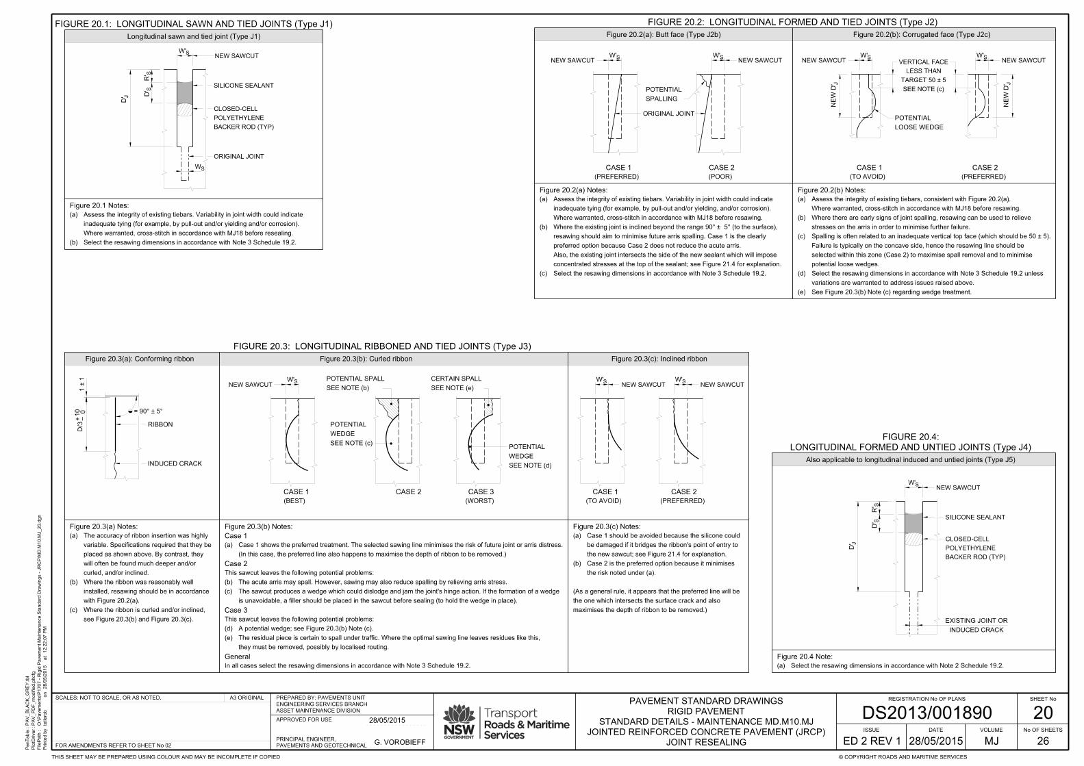
20
JOINT RESEALING
PenTable :
PlotDriver :
FilePath :
Printe
d b
y
12:2
2:0
7 P
Mat
28/0
5/2
015
on
PA
V_
BL
AC
K_
GR
EY.tbl
PA
V_P
DF_
modifie
d.pltcfg
O:\Pave
ments\P
1707 - Rigid P
ave
ment
Mainte
nance Sta
ndard Dra
win
gs - J
RC
P\M
D.M
10.M
J_20.d
gn
tetlero
b
SHEET No
No OF SHEETS
© COPYRIGHT ROADS AND MARITIME SERVICESTHIS SHEET MAY BE PREPARED USING COLOUR AND MAY BE INCOMPLETE IF COPIED
FOR AMENDMENTS REFER TO SHEET No 02
A3 ORIGINAL REGISTRATION No OF PLANS
26
ISSUE
ED 2 REV 1 MJ
VOLUME
SCALES: NOT TO SCALE, OR AS NOTED.
DATEJOINTED REINFORCED CONCRETE PAVEMENT (JRCP)
STANDARD DETAILS - MAINTENANCE MD.M10.MJ
RIGID PAVEMENT
PAVEMENT STANDARD DRAWINGS
DS2013/001890ASSET MAINTENANCE DIVISION
ENGINEERING SERVICES BRANCH
PREPARED BY: PAVEMENTS UNIT
APPROVED FOR USE
PAVEMENTS AND GEOTECHNICAL
PRINCIPAL ENGINEER,G. VOROBIEFF
28/05/2015
28/05/2015
Figure 20.3(a): Conforming ribbon Figure 20.3(b): Curled ribbon Figure 20.3(c): Inclined ribbon
Figure 20.1 Notes:
Figure 20.4 Note:
Figure 20.2(a) Notes: Figure 20.2(b) Notes:
concentrated stresses at the top of the sealant; see Figure 21.4 for explanation.
Also, the existing joint intersects the side of the new sealant which will impose
preferred option because Case 2 does not reduce the acute arris.
resawing should aim to minimise future arris spalling. Case 1 is the clearly
Where the existing joint is inclined beyond the range 90° ± 5° (to the surface),(b)
Select the resawing dimensions in accordance with Note 3 Schedule 19.2.(c)
stresses on the arris in order to minimise further failure.
Where there are early signs of joint spalling, resawing can be used to relieve(b)
potential loose wedges.
selected within this zone (Case 2) to maximise spall removal and to minimise
Failure is typically on the concave side, hence the resawing line should be
Spalling is often related to an inadequate vertical top face (which should be 50 ± 5).(c)
variations are warranted to address issues raised above.
Select the resawing dimensions in accordance with Note 3 Schedule 19.2 unless(d)
See Figure 20.3(b) Note (c) regarding wedge treatment.(e)
Figure 20.3(a) Notes:
curled, and/or inclined.
will often be found much deeper and/or
placed as shown above. By contrast, they
variable. Specifications required that they be
The accuracy of ribbon insertion was highly(a)
with Figure 20.2(a).
installed, resawing should be in accordance
Where the ribbon was reasonably well(b)
see Figure 20.3(b) and Figure 20.3(c).
Where the ribbon is curled and/or inclined,(c)
Figure 20.3(b) Notes:
Case 1
Case 2
Case 3
General
In all cases select the resawing dimensions in accordance with Note 3 Schedule 19.2.
Figure 20.3(c) Notes:
maximises the depth of ribbon to be removed.)
the one which intersects the surface crack and also
(As a general rule, it appears that the preferred line will be
Select the resawing dimensions in accordance with Note 2 Schedule 19.2.(a)
SILICONE SEALANT
W'S
S
ORIGINAL JOINT
= 90° ± 5°
D/3
010
+ –
INDUCED CRACK
SILICONE SEALANT
W'S
CASE 1
(PREFERRED)
W'S
CASE 2
(POOR)
W'S
CASE 1
(BEST)
CASE 2 CASE 3
(WORST)
W'S
CASE 1
(TO AVOID)
W'S
CASE 2
(PREFERRED)
(In this case, the preferred line also happens to maximise the depth of ribbon to be removed.)
Case 1 shows the preferred treatment. The selected sawing line minimises the risk of future joint or arris distress.(a)
ORIGINAL JOINT
SEE NOTE (b)
POTENTIAL SPALL
SEE NOTE (e)
CERTAIN SPALL
RIBBON
SPALLING
POTENTIAL
SEE NOTE (c)
WEDGE
POTENTIAL
SEE NOTE (d)
WEDGE
POTENTIAL
INDUCED CRACK
EXISTING JOINT OR
Figure 20.2(a): Butt face (Type J2b) Figure 20.2(b): Corrugated face (Type J2c)
FIGURE 20.3: LONGITUDINAL RIBBONED AND TIED JOINTS (Type J3)
LONGITUDINAL FORMED AND UNTIED JOINTS (Type J4)
FIGURE 20.4:
Also applicable to longitudinal induced and untied joints (Type J5)
NEW SAWCUT
NEW SAWCUT
NEW SAWCUT
the risk noted under (a).
Case 2 is the preferred option because it minimises(b)
the new sawcut; see Figure 21.4 for explanation.
be damaged if it bridges the ribbon's point of entry to
Case 1 should be avoided because the silicone could(a)
they must be removed, possibly by localised routing.
The residual piece is certain to spall under traffic. Where the optimal sawing line leaves residues like this,(e)
A potential wedge; see Figure 20.3(b) Note (c).(d)
This sawcut leaves the following potential problems:
NEW SAWCUTNEW SAWCUT
NEW SAWCUTNEW SAWCUT
is unavoidable, a filler should be placed in the sawcut before sealing (to hold the wedge in place).
The sawcut produces a wedge which could dislodge and jam the joint's hinge action. If the formation of a wedge(c)
The acute arris may spall. However, sawing may also reduce spalling by relieving arris stress.(b)
This sawcut leaves the following potential problems:
BACKER ROD (TYP)
POLYETHYLENE
CLOSED-CELL
BACKER ROD (TYP)
POLYETHYLENE
CLOSED-CELL
Longitudinal sawn and tied joint (Type J1)
Select the resawing dimensions in accordance with Note 3 Schedule 19.2.(b)
Where warranted, cross-stitch in accordance with MJ18 before resealing.
inadequate tying (for example, by pull-out and/or yielding and/or corrosion).
Assess the integrity of existing tiebars. Variability in joint width could indicate(a)Where warranted, cross-stitch in accordance with MJ18 before resawing.
inadequate tying (for example, by pull-out and/or yielding, and/or corrosion).
Assess the integrity of existing tiebars. Variability in joint width could indicate(a)
Where warranted, cross-stitch in accordance with MJ18 before resawing.
Assess the integrity of existing tiebars, consistent with Figure 20.2(a).(a)
W'S
CASE 1
(TO AVOID)
J
W'S
CASE 2
(PREFERRED)
LOOSE WEDGE
POTENTIAL
NEW SAWCUTNEW SAWCUT
SEE NOTE (c)
TARGET 50 ± 5
LESS THAN
VERTICAL FACE
NE
W D'J
N
EW D'
JD'
SR'
SD'
W'S
JD'
SR'
SD'
FIGURE 20.1: LONGITUDINAL SAWN AND TIED JOINTS (Type J1) FIGURE 20.2: LONGITUDINAL FORMED AND TIED JOINTS (Type J2)
W
1 ± 1

21
JOINT RESEALING
PenTable :
PlotDriver :
FilePath :
Printe
d b
y
12:2
2:0
8 P
Mat
28/0
5/2
015
on
PA
V_
BL
AC
K_
GR
EY.tbl
PA
V_P
DF_
modifie
d.pltcfg
O:\Pave
ments\P
1707 - Rigid P
ave
ment
Mainte
nance Sta
ndard Dra
win
gs - J
RC
P\M
D.M
10.M
J_21.d
gn
tetlero
b
SHEET No
No OF SHEETS
© COPYRIGHT ROADS AND MARITIME SERVICESTHIS SHEET MAY BE PREPARED USING COLOUR AND MAY BE INCOMPLETE IF COPIED
FOR AMENDMENTS REFER TO SHEET No 02
A3 ORIGINAL REGISTRATION No OF PLANS
26
ISSUE
ED 2 REV 1 MJ
VOLUME
SCALES: NOT TO SCALE, OR AS NOTED.
DATEJOINTED REINFORCED CONCRETE PAVEMENT (JRCP)
STANDARD DETAILS - MAINTENANCE MD.M10.MJ
RIGID PAVEMENT
PAVEMENT STANDARD DRAWINGS
DS2013/001890ASSET MAINTENANCE DIVISION
ENGINEERING SERVICES BRANCH
PREPARED BY: PAVEMENTS UNIT
APPROVED FOR USE
PAVEMENTS AND GEOTECHNICAL
PRINCIPAL ENGINEER,G. VOROBIEFF
28/05/2015
28/05/2015
TRANSVERSE SAWN CONTRACTION JOINTS (Type J9)
FIGURE 21.2:
ISOLATION JOINTS (Type J14)
FIGURE 21.3:
FIGURE 21.4: SEALANT RESERVOIR FAULTS FIGURE 21.5: SEALANT INSTALLATION - GENERAL
Figure 21.1(a): Butt face Figure 21.1(b): Corrugated face
Figure 21.5(a): Good practice Figure 21.5(b) : Poor practiceFigure 21.4(a): Ineffective reseal Figure 21.4(b): Short lived reseal
Figure 21.1(a) Notes: Figure 21.1(b) Notes:
Figure 21.2 Notes:
Select the resawing dimensions in accordance with Note 2 Schedule 19.2.(a)
W'S
JD'
ORIGINAL JOINT
NEW JOINT
W S
D
J
Figure 21.3 Notes:
See Figure 20.3(b) Note (c) regarding wedge treatment.(d)
unless variations are warranted to address issues raised in (a).
Select the resawing dimensions in accordance with Note 3 Schedule 19.2(c)
to minimise potential loose wedges.
should be selected within this zone (Case 2) to maximise spall removal and
50 ± 5). Failure is typically on the concave side, hence the resawing line
Spalling is often related to an inadequate vertical top face (which should be(b)
stresses on the arris to minimise further failure.
Where there are early signs of joint spalling, resawing can be used to relieve(a)
Figure 21.4(a) Notes:
the sealant will be dormant and the joint remains unsealed.
The reseal shown here actually misses the joint, hence(b)
so selection of the resawing line is important.
The sealant must bridge the moving joint and(a)
(as shown), the sealant will either tear or debond.
If the moving joint intersects the side of the sealant(a)
Figure 21.4(c) Notes:
compression movements are spread evenly throughout the sealant.
Good sealant design and installation ensures that expansion and(a)
concentrated strain at the joint will tear the sealant.
If the sealant is bonded along the bottom face, the
Hence, it is preferable that they be pushed towards the sawcut.
Care is required to prevent the fragments falling into the joint.(b)
as shown.
One possible remedy is to break off the wedge of concrete(a)
SLAB CONTRACTION SLAB CONTRACTIONINDUCER
RIBBON TYPICAL SEALANT DESIGN TYPICAL DESIGN FOR ROUTING UNSATISFACTORY DESIGN
BONDED FACES
Select the resawing dimensions in accordance with Note 3 Schedule 19.2.(b)
will impose concentrated stresses on it; see Figure 21.4 for explanation.
acute arris. Also, the existing joint intersects the side of the new sealant which
Case 1 is the clearly preferred option because Case 2 does not reduce the
resawing should aim to minimise future arris spalling.
Where the existing joint is inclined beyond the range 90° ± 5° (to the surface),(a)
WEDGE
WEAK
WEDGE
WEAK
CASE 1 CASE 2
RESAWN AND RESEALED ROUTED AND RESEALED
Also applicable to Types J15 and J16
FIGURE 21.1: TRANSVERSE FORMED AND TIED JOINTS (Type J7)
NEW SAWCUTNEW SAWCUT
SILICONE SEALANT
BACKER ROD (TYP)
POLYETHYLENE
CLOSED-CELL
JOINT FILLER
EXISTING JOINT
JD'
SD'
SR'
SW'
(TYP)
BACKER ROD
POLYETHYLENE
CLOSED-CELL
(TYP)
BACKER ROD
POLYETHYLENE
CLOSED-CELL
W'S
CASE 1
(PREFERRED)
W'S
CASE 2
(POOR)
ORIGINAL JOINT
NEW SAWCUT NEW SAWCUTW'S
CASE 1
(TO AVOID)
J
W'S
CASE 2
(PREFERRED)
LOOSE WEDGE
POTENTIAL
NEW SAWCUT
SEE NOTE (b)
TARGET 50 ± 5
LESS THAN
VERTICAL FACE
NE
W D'J
N
EW D'
NEW SAWCUT
Also applicable to Types J10, J12, and J17.
existing joint width (and hence will admit incompressible material).
it is permanently compressed to a width significantly less than the●
there are signs of deterioration, or●
Replace the joint filler if:(c)
Select the resawing dimensions in accordance with Note 2 Schedule 19.2.(b)
This detail is applicable to longitudinal and transverse J14, J15, and J16.(a)
Figure 21.4(b) Note:
Figure 21.5(a) Note: Figure 21.5(b) Note:
SEE NOTE (a)
POTENTIAL SPALL
INDUCER
RIBBON
Figure 21.4(c): Effective reseal

22
ROUTING AND SEALING OF CRACKS AND JOINTS
PenTable :
PlotDriver :
FilePath :
Printe
d b
y
12:2
2:0
9 P
Mat
28/0
5/2
015
on
PA
V_
BL
AC
K_
GR
EY.tbl
PA
V_P
DF_
modifie
d.pltcfg
O:\Pave
ments\P
1707 - Rigid P
ave
ment
Mainte
nance Sta
ndard Dra
win
gs - J
RC
P\M
D.M
10.M
J_22.d
gn
tetlero
b
SHEET No
No OF SHEETS
© COPYRIGHT ROADS AND MARITIME SERVICESTHIS SHEET MAY BE PREPARED USING COLOUR AND MAY BE INCOMPLETE IF COPIED
FOR AMENDMENTS REFER TO SHEET No 02
A3 ORIGINAL REGISTRATION No OF PLANS
26
ISSUE
ED 2 REV 1 MJ
VOLUME
SCALES: NOT TO SCALE, OR AS NOTED.
DATEJOINTED REINFORCED CONCRETE PAVEMENT (JRCP)
STANDARD DETAILS - MAINTENANCE MD.M10.MJ
RIGID PAVEMENT
PAVEMENT STANDARD DRAWINGS
DS2013/001890ASSET MAINTENANCE DIVISION
ENGINEERING SERVICES BRANCH
PREPARED BY: PAVEMENTS UNIT
APPROVED FOR USE
PAVEMENTS AND GEOTECHNICAL
PRINCIPAL ENGINEER,G. VOROBIEFF
28/05/2015
28/05/2015
NOTES
SCHEDULE 22.1 (S22.1)
METHOD
SCHEDULE 22.2 (S22.2)
R 85
Table 22.2 Notes:
SYMBOL DESCRIPTION
W C
W
W
W
W
W
W
SP
R1
R2
85
S
U
Width of silicone sealant
Width of crack (without spalling)
Width of crack plus spalling
Width of rout - 1st pass
Width of rout - 2nd pass
85% spalled width. (b)
TABLE 22.2: NOMENCLATURE
TABLE 22.1: ROUT DIMENSIONS - TIED AND STITCHED CASES
Table 22.1 Notes:
R R B SW
(mm)
Rout width
(H = 5 mm)
15 mm cut to ½ round
B
(H )
and size
Backer rod shape
B
B
(H = 15 mm)
30 mm cut to ½ round
(H = 14 mm)
of height 14 mm
50 mm, slit segment
15 ± 3
30 ± 5
50 ± 7
(b)
type
Sealant
D
(mm)
Rout depth
15 (+ 5, - 0)
30 (+ 7, - 0)
30 (+ 7, - 0)
10 (+ 5, - 0)
11 (+ 5, - 0)
7 (+ 3, - 0)
R
(mm)
Sealant recess
D
(mm)
Sealant thickness
4 (+ 2, - 0)
3 (+ 2, - 0)
3 (+ 2, - 0)
RS
SD
BH
RD
W R
W or WU S
Polyurethane
Silicone or
Polyurethane
Polyurethane
Width of polyurethane sealant
Refer to Note (b) Schedule 23.1 for commentary.(b)
Refer to Details T-X, MJ23 for applicability.(a)
increase friction values.
Where a polyurethane is used in a longitudinal joint, its surface must be blinded with sand to11.
that joint so that the polyurethane is discontinuous.
Where a polyurethane sealant will cross an untied joint, a joint filler must be placed within10.
section, including any underlying cracks.
At slab edges and formed joints, sealants must extend down the vertical face of the routed9.
actions of wind or sealant installation.
held in place by a suitable flexible adhesive such that the rod will not be dislodged with the
of the reservoir so as to seal the exposed crack/joint. If necessary, the backer rod must be
accurately slit in a jig to the required shape. The backer rod is to be depressed to the bottom
The backer rod shown in Table 22.1 must be continuous closed-cell polyethylene. It must be8.
accordance with T380.
(None) visual rating category is achieved. The adhesion of the sealant must be tested in
joint faces must be tested in accordance with T379. An acceptable result is when Grade 1
concrete faces have been prepared in accordance with the guidelines. The cleanliness of the
deleterious to the adhesion of the sealant. Grit blasting is not required when the routed
free from all loose debris, pulverised concrete dust, and other material which may be
At the time of sealant installation, side walls of the reservoir must be thoroughly clean and7.
other times due to contraction and curling.
Crack widths should be assessed in the warmer part of the day because they will increase at6.
will be different to those in untied joints because of the differing magnitude of movement.
the required operating parameters of the sealant. The design of sealants in tied joints(b)
the width of spalling.(a)
The resawing/routing width is typically governed by two criteria:5.
will rarely be feasible for cracks.
For (re)sealing of joints, sawing should be considered in preference to routing, but sawing4.
before routing/sawing (to reduce the stress on sealants).
Wherever possible, cracks should be stitched; see MJ18. Stitching should be completed3.
to clean the faces to maximise sealant adhesion.(b)
to produce a reservoir shape with vertical sides and which is suitable for sealing.(a)
The purpose of routing and resawing is:2.
routing cut for the sawcut.
treatments detailed in MJ19-MJ21 are equally applicable to routing by substitution of a
where resawing is unsuitable. Where the joint to be routed is inclined and/or curled, the
This procedure is mainly applicable to treatment of cracks but may also be used for joints1.
Allow trafficking only after sealant has become tack free.9.
For polyurethanes, apply sand to the surface.
In sawcuts, install sealant in accordance with MJ19-MJ21.
In routings, install sealant in accordance with Table 22.1.8.
Install backer rod to provide the required sealant depth.7.
Inspect to ensure effective removal of all loose debris.6.
done immediately after sawing/routing and before the residue dries.
Clean out joints/cracks with high pressure water. This must be5.
Schedule 23.5 as applicable.
Repair joints and cracks in accordance with Schedule 23.1 to4.
Determine required rout width, W > W .3.
Mark areas to be treated.2.
Work Method Statements (SWMS).
Establish traffic control and work safety in accordance with Safe1.
S
of 50 ± 7 mm should only be varied after careful consideration and after suitable trialling.
suggested for logistical purposes only and may be varied if deemed desirable. However, the maximum width
Routing widths listed in Table 22.1 are limited to 3 categories. The values (and the number of 3) are(c)
In tied joints, polyurethane is preferable to silicone where distillate fuels are likely to be in concentration.(b)
than 18 mm and that all dimensions satisfy criteria in accordance with Table 19.1.
For untied/unstitched cases, this table may be used on the condition that the sealant is silicone of width less(a)
NOT TO SCALE
FIGURE 22.1: TYPICAL ROUTING APPLICATIONS
KE
RB (
TIE
D)
KE
RB (
TIE
D)
J1
J2
J3
OR
ORJ2
J9
J9
J2
J2J2J2
J7 J7
J14
UN
TIE
D J
OIN
T
(EG
J14
J15
J4
),
,
V
23OR
X
23
W
23
X
23
W
23
U
23
T
23
T
23
X
23
T
23OR
U
23
X
23
SEE MJ18
STITCHING
J9J10OR
J9 J10OR
OR
J10
J9 J10OR

23
ROUTING AND SEALING OF CRACKS AND JOINTS
PenTable :
PlotDriver :
FilePath :
Printe
d b
y
12:2
2:1
1 P
Mat
28/0
5/2
015
on
PA
V_
BL
AC
K_
GR
EY.tbl
PA
V_P
DF_
modifie
d.pltcfg
O:\Pave
ments\P
1707 - Rigid P
ave
ment
Mainte
nance Sta
ndard Dra
win
gs - J
RC
P\M
D.M
10.M
J_23.d
gn
tetlero
b
SHEET No
No OF SHEETS
© COPYRIGHT ROADS AND MARITIME SERVICESTHIS SHEET MAY BE PREPARED USING COLOUR AND MAY BE INCOMPLETE IF COPIED
FOR AMENDMENTS REFER TO SHEET No 02
A3 ORIGINAL REGISTRATION No OF PLANS
26
ISSUE
ED 2 REV 1 MJ
VOLUME
SCALES: NOT TO SCALE, OR AS NOTED.
DATEJOINTED REINFORCED CONCRETE PAVEMENT (JRCP)
STANDARD DETAILS - MAINTENANCE MD.M10.MJ
RIGID PAVEMENT
PAVEMENT STANDARD DRAWINGS
DS2013/001890ASSET MAINTENANCE DIVISION
ENGINEERING SERVICES BRANCH
PREPARED BY: PAVEMENTS UNIT
APPROVED FOR USE
PAVEMENTS AND GEOTECHNICAL
PRINCIPAL ENGINEER,G. VOROBIEFF
28/05/2015
28/05/2015
SCHEDULE 23.1 (S23.1)
85
the economics of doing a single rout versus multiple passes.(ii)
of the capacity of the router to follow its path.
the curvature (or "crookedness") of the spalled crack, in terms(i)
depending on factors such as:
selection criteria for the rout width may differ between sites,
which is abbreviated to "85% spalled width" or W . However,
section. This is referred to as the "85th percentile spalled width",
about 85% of the total length of spalled crack within a selected
The width of rout should generally be such that it will impact on(b)
SCHEDULE 23.2 (S23.2)
R
R
C
85
SCHEDULE 23.3 (S23.3)
R
R
SCHEDULE 23.4 (S23.4)
S
T
-
DETAIL
PLAN
U
-
DETAIL
PLAN
V
-
DETAIL
PLAN
W
-
DETAIL
PLAN
W1
-
SECTION
X1
-
SECTION
SP
C
R1
R2
S R
SP
R
S UW OR W
W
SP
W1
-
W1
-
R
ORIGINAL JOINT OR CRACK
W OR W WU S R
R
SP
X1
-
X1
-
FILLER
U US
R
W
ROUT WIDTH
W
W
W
WWW
18/22 # MAX
W
SILICONE OR POLYURETHANE AS APPLICABLE
POLYURETHANE
CLOSED-CELL POLYETHYLENE BACKER ROD (TYP)
CLOSED-CELL POLYETHYLENE BACKER ROD (TYP)
where structural spall repairs are not required.
cases. It is applicable only to tied and/or stitched applications
is not feasible. It is applicable to both longitudinal and transverse
This procedure is applicable to joints and cracks where sawcutting(a)
Typical Routing Procedure DETAIL T
the 85% spalled width W < 5 mm (NOM).(ii)
the crack width W < 0.5 mm.(i)
Routing will generally not be warranted where:(c)
Tied Longitudinal Joint Routing Procedure DETAIL U
W > 18 mm: Seal with polyurethane
W ≤ 18 mm: Seal with silicone(e)
For saw and seal dimensions: see MJ19-MJ21.
For rout and seal dimensions: see Table 22.1.(d)
economics of doing a single cut versus multiple passes.
may differ between sites depending on factors such as the
spalled joint within a selected section. However, the width
be such that it will impact on about 85% of the total length of
The cutting width (either sawn or routed) should generally(c)
Sawcutting should always be considered before routing.(b)
stitched, and have only minor spalling.
This procedure is applicable to longitudinal joints which are tied or(a)
Tied Transverse Joint Routing Procedure DETAIL V
W > 22 mm: Seal with polyurethane
W ≤ 22 mm: Seal with silicone(e)
For saw and seal dimensions: see MJ19-MJ21.
For rout and seal dimensions: see Table 22.1.(d)
doing a single cut versus multiple passes.
between sites depending on factors such as the economics of
joint within a selected section. However, the width may differ
such that it will impact on about 85% of the total length of spalled
The cutting width (either sawn or routed) should generally be(c)
Sawcutting should always be considered before routing.(b)
and/or stitched and which have only minor spalling.
This procedure is applicable to transverse joints which are tied(a)
ACCORDANCE WITH MJ24 AND MJ25
USE A STRUCTURAL REPAIR IN
LOCALISED WIDE SPALL
DETAIL T, U, OR V AS APPLICABLE
TREAT IN ACCORDANCE WITH
X
-
DETAIL
PLAN
S
IN ACCORDANCE WITH MJ19-MJ21
RESAW AND RESEAL
IN ACCORDANCE WITH MJ19-MJ21
SILICONE SEALANT
SCHEDULE 23.5 (S23.5)
R
R
R
S
Untied Joint Routing Procedure DETAIL X
Detail T, U, or V as applicable.
Install the sealant over the full length of routed crack plus repair, in accordance with(iv)
Repair the wide spall in accordance with MJ24 and MJ25.(iii)
Insert a temporary filler to width W .(ii)
a later date may damage the repair).
Rout (or sawcut) the length of crack (or joint) adjoining the wide spall. (Routing or sawing at(i)
The suggested sequence of operations is as follows:(b)
structural repair is needed. It is applicable only to tied or stitched joints and cracks.
This procedure is applicable to multiple spalling types where a combination of routing and(a)
Combined Routing and Repairing Procedure DETAIL W
Install silicone sealant over the full length of joint in accordance with MJ19-MJ21.(iv)
Sawcut (or rout) the length of spalled joint (excluding the repair) in preparation for sealing.(iii)
Prepare and repair the wide spall in accordance with MJ24 and MJ25. Allow adequate curing time.(ii)
Insert a temporary filler to width W .(i)
The suggested sequence of operations (following routing) is as follows:(d)
22 mm in transverse joints
18 mm in longitudinal joints# adopt :
: treat in accordance with MJ24 and MJ25.For W > 57 mm
: treat in accordance with Detail XFor 18/22 # mm < W = 57
: resaw and seal in accordance with MJ19-MJ21For W = 18/22 # mm(c)
(of width designed in accordance with MJ19-MJ21).
Because of the magnitude of cyclic movement, at least part of the repair width must be a silicone(b)
expansion, untied butt) and which contain sections of substantial spalling.
This procedure is applicable to untied joints, either longitudinal or transverse (such as isolation,(a)
IN ACCORDANCE WITH MJ24 AND MJ25
USE A STRUCTURAL REPAIR
SPALLED WIDTH
W
CRACK WIDTH
W
ROUT No.1
W
ROUT No.2
W
W AND W
W
W = 18/22 # MAX

24
JOINT SPALL REPAIRS
PenTable :
PlotDriver :
FilePath :
Printe
d b
y
12:2
2:1
3 P
Mat
28/0
5/2
015
on
PA
V_
BL
AC
K_
GR
EY.tbl
PA
V_P
DF_
modifie
d.pltcfg
O:\Pave
ments\P
1707 - Rigid P
ave
ment
Mainte
nance Sta
ndard Dra
win
gs - J
RC
P\M
D.M
10.M
J_24.d
gn
tetlero
b
SHEET No
No OF SHEETS
© COPYRIGHT ROADS AND MARITIME SERVICESTHIS SHEET MAY BE PREPARED USING COLOUR AND MAY BE INCOMPLETE IF COPIED
FOR AMENDMENTS REFER TO SHEET No 02
A3 ORIGINAL REGISTRATION No OF PLANS
26
ISSUE
ED 2 REV 1 MJ
VOLUME
SCALES: NOT TO SCALE, OR AS NOTED.
DATEJOINTED REINFORCED CONCRETE PAVEMENT (JRCP)
STANDARD DETAILS - MAINTENANCE MD.M10.MJ
RIGID PAVEMENT
PAVEMENT STANDARD DRAWINGS
DS2013/001890ASSET MAINTENANCE DIVISION
ENGINEERING SERVICES BRANCH
PREPARED BY: PAVEMENTS UNIT
APPROVED FOR USE
PAVEMENTS AND GEOTECHNICAL
PRINCIPAL ENGINEER,G. VOROBIEFF
28/05/2015
28/05/2015
TABLE 24.1: CLASSIFICATION OF SPALLS AND SELECTION OF REPAIR METHOD FIGURE 24.1
FIGURE 24.2: TYPE SD - SHALLOW DISCRETE SPALLS FIGURE 24.3: TYPE SC - SHALLOW CONTINUOUS SPALLING
(a)Type Dimensions Treatment
AR
Arris rounding
(no limit on depth)
W < 30 mmSee Figure 25.1 for options
See Figure 24.1(a)
Minor spall M
See Figure 24.1(b)
- Discrete SD
Shallow spall
See Figure 24.1(c)
- Continuous SC
Shallow spall
(no limit on depth)
W ≤ 50 mm
H ≤ D/2
W > 50 mm
See Figure 24.3
Thin bonded repairs
Deep spall DH > D/2
W > 50 mm
D = Thickness of baseH = Depth of SpallW = Width of Spall(a)
Figure 24.2(a): Plan view
Figure 24.2(b): Stage 1 (Section view)
Figure 24.2(c): Stage 2 (Section view)
Figure 24.2(a) Notes:
Remove any existing sealant to a minimum of 100 mm beyond the patch perimeter.(b)
100 mm and be at least 20 mm beyond all unsound concrete.
Mark out the square or rectangular perimeter area to be replaced. This area must have minimum dimensions of(a)
Figure 24.2(b) Notes:
scabbling tool is suitable for this removal.
Remove the concrete within the perimeter groove to produce a reasonably even surface. A single or multi-head(e)
shattered aggregate or concrete.
is recommended for minimising ingress of grit into joints and cracks. The compressed air is intended to remove any
Clean out the patch using a vacuum cleaner and/or oil-free compressed air (plus wire-brush if required). The vacuum(f)
Figure 24.2(c) Notes:
the patch material is not sucked dry). Maintain the faces in a moist condition until the next stage.
For cementitious patches, saturate all patch faces with water (or wet rags) for at least 10 hours (to ensure that
For epoxy resin patches, prime the exposed surfaces in accordance with the manufacturer's recommendations.(h)
Immediately before placing the patch material, remove all free water (using oil-free compressed air and/or rags).(j)
Prime all surfaces by brushing with cement grout or other notified bonding agent.(k)
the primer must be protected against drying.
Place the repair material into the patch within the time limit specified by the manufacturer. Where a delay occurs,(l)
edges, and corners. Provide a timber-float or textured surface.
Thoroughly compact the material using a vibrating hammer, taking special care to work fine material into all faces,(m)
reaches the low-sheen condition.
Cementitious repairs must be cured with hydrocarbon resin curing compound. It must be applied as soon as the mix(n)
texture. Secure all edges of the sheeting to prevent drying.
Cover the patch with moist hessian and then polythene sheeting as soon as possible without marking the surface(o)
Figure 24.1(a): Minor (M) Figure 24.1(b): Shallow Discrete (SD) Figure 24.1(c): Shallow Continuous (SC)
Figure 24.3 Notes:
EXISTING SLAB JOINT
SAWCUTS
DEFINED WITH STRAIGHT
PERIMETER OF REPAIR
CONCRETE PATCH
THIN BONDED
SEALANT
SEALANT REMOVED
-
-
JOINT FORMER
PERIMETER GROOVE
DOWN TO SOUND CONCRETE
REMOVE FAILED AREA
OR EXPANSION JOINT, OR
EXISTING ISOLATION
FORMING GROOVE
SPALL PROFILE
S
GROOVE
PERIMETER
W
PATCH REPAIR PATCH REPAIR
JOINT SEALANT
NEW JOINT FILLER
DEBONDING STRIP
1
2
EDGE OF SPALLING
GROOVES
PERIMETER
OR CRACK
CONSTRUCTION JOINT
CONTRACTION OR
SPALL PROFILE
> 50
> 50
> 50
20 MIN100 MIN
100 MIN20 MIN
MIN
100
MIN
100
MIN
100 5 THICK JOINT FORMER
UNIFORM DEPTH
30 MIN
FORMING GROOVE10 MIN
MIN WIDTH OF REPAIR = 200
100 MIN
100 MIN 20 MIN
15 MIN20 MIN
15 MIN
10 MIN
24.2(b)
24.2(c)
20 MIN
PERIMETER GROOVE
15 MIN
MARK OUT OF PERIMETER
Table 24.1 Note:
See MJ12-MJ17
Full-depth repairs
Rout and seal; see MJ22 and MJ23:At Cracks
or Rout and seal; see MJ22 and MJ23
Resaw and seal; see MJ19-MJ21:At Joints
> 50
5 - 10 mm (TYP) wide.for tied construction joints:●
9 - 12 mm (TYP) wide.for PCP contraction joints:●
20 - 30 mm (TYP) wide.for isolation and expansion joints:●
be of a width suitable for the specific joint type, and desirably 2 to 5 mm wider than the existing joint, hence:●
extend at least 100 mm beyond each end of the patch perimeter.●
be at least 10 mm deeper than the deeper patch (where 2-sided).●
The forming groove must:
four slab corners, a former must be placed along each joint.
Saw or rout a joint forming groove along the line of the joint (to hold the joint former). For repairs at the junction of(c)
be rough; see Note 2 Schedule 25.2.
a single-head scabbling tool or a router and template. This must form vertical edges to the patch. All edges must
Chase out a perimeter groove around the other three sides, to a minimum depth of 15 mm. This should be done with(d)
paths and gaps where repair material could escape or contact adjoining slabs. See Notes 3 and 4 Schedule 25.2.
Fix a joint former securely into the forming groove so that the top is flush with the finished surface level. Caulk all(g)
can be roughened with an angle-grinder to maximise sealant bond.
resawing and sealing of joints is to follow, joint cleaning will be achieved during that program. Otherwise, the faces
Clean and seal the joint in accordance with MJ19-MJ21, and after removing the joint former. Where a program of(q)
Curing and protection should be maintained for a minimum of 24 hours, but preferably three days.(p)
See Figure 24.2
Thin bonded repairs
SPALLS
CONTINUOUS
DISCRETE SPALLS
CRACK
FULL-DEPTH
CRACK
FULL-DEPTH(INCLUDE JOINT)
< 50
< 50
< 50
CRACK
FULL-DEPTH
Chase this sawcut with a router to roughen the vertical faces. See also Note 2 Schedule 25.2.(c)
Initiate the perimeter groove by sawcutting.(b)
The minimum depth of patch must be 30 mm.(a)
Follow the procedure in accordance with Figure 24.2, except:

25
JOINT SPALL REPAIRS
PenTable :
PlotDriver :
FilePath :
Printe
d b
y
12:2
2:1
5 P
Mat
28/0
5/2
015
on
PA
V_
BL
AC
K_
GR
EY.tbl
PA
V_P
DF_
modifie
d.pltcfg
O:\Pave
ments\P
1707 - Rigid P
ave
ment
Mainte
nance Sta
ndard Dra
win
gs - J
RC
P\M
D.M
10.M
J_25.d
gn
tetlero
b
SHEET No
No OF SHEETS
© COPYRIGHT ROADS AND MARITIME SERVICESTHIS SHEET MAY BE PREPARED USING COLOUR AND MAY BE INCOMPLETE IF COPIED
FOR AMENDMENTS REFER TO SHEET No 02
A3 ORIGINAL REGISTRATION No OF PLANS
26
ISSUE
ED 2 REV 1 MJ
VOLUME
SCALES: NOT TO SCALE, OR AS NOTED.
DATEJOINTED REINFORCED CONCRETE PAVEMENT (JRCP)
STANDARD DETAILS - MAINTENANCE MD.M10.MJ
RIGID PAVEMENT
PAVEMENT STANDARD DRAWINGS
DS2013/001890ASSET MAINTENANCE DIVISION
ENGINEERING SERVICES BRANCH
PREPARED BY: PAVEMENTS UNIT
APPROVED FOR USE
PAVEMENTS AND GEOTECHNICAL
PRINCIPAL ENGINEER,G. VOROBIEFF
28/05/2015
28/05/2015
FIGURE 25.1: TREATMENT OF MINOR ARRIS ROUNDING
Figure 25.1(a): Option 1 Figure 25.1(b): Option 2 Figure 25.1(c): Option 3
Figure 25.1(a) Notes: Figure 25.1(b) Notes: Figure 25.1(c) Notes:
S
SCHEDULE 25.1 (S25.1) SCHEDULE 25.2 (S25.2)
NOTES METHOD
Scope
Workmanship
Spall types
Minimum repair depth
Workmanship
Patch preparation
Joint formers
S SS S S
50 M
AX
20 M
IN
FILLER
EXISTING FACE
ROUNDING ON
JOINT FACE
EXPOSED
W'
EXISTING SLAB
DEBONDING STRIP
OR BACKER ROD
RESIDUAL FILLER
EXISTING SLAB
EPOXY PATCH
NEW FILLER
FACE
EXPOSED
EXISTING SLAB
REMOVAL
SECTION FOR
EXISTING SLAB
SEALANT
S
STRIP
DEBONDING DEBONDING STRIP
R' S
D' S
SECTION FOR REMOVAL
S
D' S
NEW MATERIAL
S
NEW MATERIAL
of seals to view the extent of cracking.
Simple investigation techniques include tapping around the failure with a steel rod, and removal�
of deep spalling may look similar to shallow spalling.
It is desirable to determine the extent of failure before commencing repairs. The early stages�
Each spall type is treated differently; see Table 24.1.�
Joint spall repairs are typically classified as shown in Table 24.1.3.
to scabble without causing further spalling.
unacceptable. It is therefore preferable that failed concrete be chased out rather than sawn. Sawn faces are difficult
All bonded faces (both vertical and horizontal) must be rough to maximise bond strength. Sawn or smooth faces are2.
Thickness D' should be 7 mm minimum and the shape ratio W : D should be between 3 : 1 and 5 : 1.
For this application, the width may be varied between suggested limits of 18 mm and 60 mm.
(Routing is not required here.)
Table 22.1 provides guidelines for polyurethanes but gives only two options to suit routing widths.
In tied joints, a polyurethane can be used in lieu of the silicone, in which case higher width limits apply.(d)
18 mm maximum in longitudinal joints.
The controlling factor for the use of this option is likely to be the limit on silicone width, namely,(c)
resin patch.
This method is the same as Figure 25.1(b) except that it removes the step of placing an epoxy(b)
for the silicone option in Figure 25.1(a).
This option is suitable where the rounding and/or spalling exceeds the recommended operating range(a)
For the sealant design, refer to Figure 25.1(a).(d)
A polyurethane may be used in lieu of the epoxy resin.(c)
advanced than in MJ24.
This treatment is generally consistent with MJ24 but assumes the spalling and/or rounding is much less(b)
and/or dimensions) for the silicone option in Figure 25.1(a)
This option is suitable where the rounding and/or spalling exceeds the recommended operating range (in shape(a)
STAGE 1 STAGE 2
PLACE SEALANT.
PLACE NEW MATERIAL.
THE EXPOSED FACE.
FIX A SUITABLE FILLER TO
STAGE 1 STAGE 2 STAGE 3
CONCRETE AS SHOWN.
BY SAWCUTTING AND REMOVING
PROVIDE SQUARED RESERVOIR PLACE SEALANT.
EPOXY REPAIR.
FIX A SUITABLE FILLER AND PLACE
REMOVE FAILED MATERIAL.
STAGE 1 STAGE 2
NEED NOT BE INCREASED.
INCREASED AS SHOWN, BUT DEPTH
THE EFFECTIVE SEALANT WIDTH IS
PLACE SEALANT.
FIX A SUITABLE FILLER AND PLACE NEW MATERIAL.
SAWCUTTING AND REMOVING CONCRETE AS SHOWN.
PROVIDE SQUARED RESERVOIR BY
can be used in conjunction with slab removal (as shown on MJ12-MJ17) with only minor adaptation.
not involve full-depth slab removal. However, they are intended to cover many applications and so
This method applies to joints, cracks, and edges. The diagrams show repairs in situations which do1.
unless close attention to detail is given to every aspect. Also refer to Schedule 25.2.
Spall repairs are very sensitive to standards of workmanship and will yield a low success rate2.
so scabbling should be limited to the extent necessary to remove all unsound concrete.
Beyond these thicknesses, there is no value in making the repair deeper than necessary and
30 mm for cementitious repairs.●
10 mm for epoxy resin repairs.●
The practical minimum depth is:4.
the microtexture of scabbled faces and into corners and edges.
It is critical that a thorough bond be achieved over all patch faces. This requires that mortar be worked into
protection against early stress.●
curing.●
concrete/mortar compaction.●
bond strength.●
roughness and cleanliness of the parent concrete.●
The critical factors for success include:1.
without damaging the patch, it must be debonded and also preferably collapsible.
against the patch that is bonded to flexible material against adjacent slabs. To facilitate the removal of the filler
transferring stress into the patch. Some situations may require a composite former/filler comprising stiffer material
Any temporary joint formers or fillers must be flexible and compressible enough to absorb movement without4.
intersection of four slab corners, a former must be placed in each joint.
adjoining slabs and must not bridge across joints (including tied joints, which hinge due to curling). For repairs at the
It is critical that the repair not be stressed before it achieves adequate strength. It must be totally isolated from3.
For widths > 18 mm: not feasible, assess alternatives. Seek specialist advice.●
For design widths ≤ 18 mm, use a silicone in accordance with Table 19.1.●
For untied longitudinal joints:(iii)
Use a silicone in accordance with Table 19.1.
For untied transverse:(ii)
Use a silicone designed in accordance with Table 19.2. Adopt W' as low as feasible.
For tied joints, transverse or longitudinal:(i)
Recommendations are as follows:
The sealant type and width must be designed in accordance with MJ19-MJ21.(d)
This should be the key issue in assessing the suitability of this option.
The silicone is most likely to fail by adhesion failure (debonding) at the arris rounding.(c)
This method is suitable for both longitudinal and transverse joints, either tied or untied.(b)
rounding will result in spalling of the new edge.
This option is suitable where the rounding is only minor, but placement of concrete against that(a)
W'
NEW MATERIALNEW MATERIAL
W'
NEW MATERIAL
R'
W'
D'
W'

26
ANCHOR DEFECT REPAIRS
PenTable :
PlotDriver :
FilePath :
Printe
d b
y
12:2
2:1
6 P
Mat
28/0
5/2
015
on
PA
V_
BL
AC
K_
GR
EY.tbl
PA
V_P
DF_
modifie
d.pltcfg
O:\Pave
ments\P
1707 - Rigid P
ave
ment
Mainte
nance Sta
ndard Dra
win
gs - J
RC
P\M
D.M
10.M
J_26.d
gn
tetlero
b
SHEET No
No OF SHEETS
© COPYRIGHT ROADS AND MARITIME SERVICESTHIS SHEET MAY BE PREPARED USING COLOUR AND MAY BE INCOMPLETE IF COPIED
FOR AMENDMENTS REFER TO SHEET No 02
A3 ORIGINAL REGISTRATION No OF PLANS
26
ISSUE
ED 2 REV 1 MJ
VOLUME
SCALES: NOT TO SCALE, OR AS NOTED.
DATEJOINTED REINFORCED CONCRETE PAVEMENT (JRCP)
STANDARD DETAILS - MAINTENANCE MD.M10.MJ
RIGID PAVEMENT
PAVEMENT STANDARD DRAWINGS
DS2013/001890ASSET MAINTENANCE DIVISION
ENGINEERING SERVICES BRANCH
PREPARED BY: PAVEMENTS UNIT
APPROVED FOR USE
PAVEMENTS AND GEOTECHNICAL
PRINCIPAL ENGINEER,G. VOROBIEFF
28/05/2015
28/05/2015
CASE 6
KE
RB (
TIE
D)
OR
OR
CASE 4
CASE 5CASE 3
CASE 2 CASE 7
CASE 1
FIGURE 26.1: TYPICAL JPCP TERMINAL ANCHOR DEFECTS
JRCP JRCP JRCP
J2
OR
OR
J9 OR J10
J14
(REINFORCED)
SLAB
APPROACH
BRIDGE
ANCHORA
NOT TO SCALE
J7
J6
J1 J1
J2
J3 J3
J2
JRCP
JRCP JRCP
CASE 1: Shrinkage cracking over anchors
CASE 2: Transverse joint spalls
CASE 3: Corner cracking
CASE 4: Anchor rotation / sliding
CASE 5: Tranverse cracking
CASE 6: Longitudinal cracking
CASE 7: Longitudinal joint spalls
NOTES
Anchors
SCHEDULE 26.1 (S26.1)
of various anchor designs.
Refer to Volume CJ Jointed Reinforced Concrete Pavement for standard details1.
only and is adjusted to suit grade and drainage requirements.
is deleted and the subbase is extended to the anchor. The depth of the drain is nominal
anchor falls towards the anchor. Where the grade falls away from the anchor, the drain
Anchor drains are constructed only where the longitudinal grade on that side of the3.
JRCP ANCHOR DEFECT CASES
SCHEDULE 26.2 (S26.2)
Due to the serious repercussions of this defect, seek specialist advice.
and/or SFCP-R terminal slabs and/or bridge abutment/deck damage.
at the J14 or F7 and/or F4 joints. It may also lead to buckling of the JRCP
of the JRCP and/or SFRP-R terminal slabs and/or bridge approach slab
This defect usually manifests itself in the form of faulting and/or crushing(a)
JRCP terminal slabs constructed before 2003, this dimension was 4500 ± 500.2.
Rout and seal cracks in accordance with MJ22 and MJ23 if warranted.(a)
Repair in accordance with MJ24 and MJ25 if warranted.(a)
if approved) if secondary cracking occurs.
Repair in accordance with Case 9 shown on MJ12 (or Case 8(a)
Rout and seal cracks in accordance with MJ22 and MJ23 if warranted.(a)
Rout and seal cracks in accordance with MJ22 and MJ23 if warranted.(a)
Repair in accordance with MJ24 and MJ25 if warranted.(a)
SUBGRADE BEAM
(TY
PE 1
2)
1 2
00
MIN
600
LCSLCS
JRCP
BA
SE
D
MIN
600
LCS
JRCP
BA
SE
D
D
+– 0
2001100
CONSTRUCTION JOINT
AND BOTTOM)
MESH (TOP
JOINT
CONSTRUCTION
SU
BB
AS
E
MESH (TOP ONLY)
FOR ROAD SKEW ≥ 84°
FIGURE 26.2: SCHEMATIC TERMINAL DESIGN AT BRIDGES
TY
PE 1
2 : 1
200
MESH (TOP ONLY)
J14
JRCP
J9
SU
BB
AS
E
2
LENGTH OF SLABMAX
SEE NOTE 1 (S26.1)
JRCP
MAX2
LENGTH OF SLAB
MESH (TOP AND BOTTOM)
MESH (TOP ONLY)
SEE NOTE 2 S26.1
SEE NOTE 1 (S26.1)
JRCP
J10OR
J9 J10OR
SUBSURFACE DRAIN
FILLER
POSSIBLE THICKENING
SEE NOTE 3, S26.1
ANCHOR DRAIN
SEE NOTE 3, S26.1
ANCHOR DRAIN
POSSIBLE THICKENING
FIGURE 26.3: SCHEMATIC TERMINAL DESIGN AT FLEXIBLE PAVEMENT
BRIDGE
APPROACH SLAB
BRIDGE TERMINAL SLAB
4 000 MIN
12 000 MAX
1 500 MIN
2
PAVEMENT
FLEXIBLETERMINAL SLAB
1 500 MIN
2