Statewide Airfield Pavement Management Program Airport ...
154
Ormond Beach Municipal Airport (OMN) Reliever Airport District 5 Statewide Airfield Pavement Management Program Airport Pavement Evaluation Report November 2019 FLORIDA DEPARTMENT OF TRANSPORTATION AVIATION AND SPACEPORTS OFFICE
-
Upload
khangminh22 -
Category
Documents
-
view
2 -
download
0
Transcript of Statewide Airfield Pavement Management Program Airport ...

Ormond BeachMunicipal Airport (OMN)Reliever AirportDistrict 5
Statewide Airfield PavementManagement Program
Airport PavementEvaluation ReportNovember 2019
F L O R I D A D E PA RT M E N T O F T R A N S P O RTAT I O NAV I AT I O N A N D S PA C E P O R T S O F F I C E
Ormond Beach Municipal
Airport (OMN)
Florida Department of Transportation
Prepared by: FDOT Aviation and Spaceports Office 605 Suwannee Street Tallahassee, Florida 32399-0450

Executive Summary ................................................................................................................10
Program Background ..........................................................................................................10
Summary of Results ............................................................................................................11 Pavement Condition Index (Latest Inspection) ................................................................................ 11 Forecasted Pavement Condition Index 2020-2029 ......................................................................... 12 Major Rehabilitation Planning 2020-2029 ....................................................................................... 13
Summary of Ormond Beach Municipal Airport .................................................................14
Chapter 1 – Introduction .........................................................................................................16
1.1 Background ...................................................................................................................16
1.2 Statewide Airfield Pavement Management Program (SAPMP) Update 2018-2019 ....16
1.3 Organization...................................................................................................................18 1.3.1 Florida Department of Transportation Aviation and Spaceports Office Program Manager ....... 18 1.3.2 Participating Florida Public-Use and Publicly Owned Airports ................................................ 18 1.3.3 Florida Department of Transportation District Offices ............................................................. 18 1.3.4 Consultant ............................................................................................................................. 18
1.4 Purpose of Airport Pavement Evaluation Report ........................................................20
1.5 History of the Program ..................................................................................................20
1.6 Federal Aviation Administration (FAA) ........................................................................22
1.7 FDOT SAPMP Objectives and Components ................................................................22 1.7.1 Program Objectives ............................................................................................................... 22 1.7.2 Program Components ........................................................................................................... 22
1.8 References .....................................................................................................................26
Chapter 2 – Methodology .......................................................................................................28
2.1 Airfield Pavement Database ..........................................................................................28
2.2 Airfield Pavement System Inventory ............................................................................28 2.2.1 Pavement Management Program Network Definition Terminology ......................................... 29
2.3 Airfield Pavement Structure ..........................................................................................31 2.3.1 Pavement Structure Types .................................................................................................... 31
2.4 Airfield Pavement Work History ...................................................................................33 2.4.1 Airfield Pavement Record Keeping ........................................................................................ 33
2.5 Airfield Pavement Traffic...............................................................................................33
2.6 Airfield Pavement Condition Index (PCI) Survey .........................................................33 2.6.1 PCI Survey Methodology ....................................................................................................... 33 2.6.2 Pavement Distress Types ...................................................................................................... 35

2.6.3 PCI Survey Inspection Procedures ........................................................................................ 39 2.6.4 Updates to the ASTM D5340-12 ............................................................................................ 40
Chapter 3 – Airfield Pavement System Inventory .................................................................43
3.1 Airfield Pavement Network Information .......................................................................43 3.1.1 Previous and/or Anticipated Airfield Pavement Construction .................................................. 43 3.1.2 Estimated Pavement Age ...................................................................................................... 45 3.1.3 Functional Use Classification ................................................................................................. 47 3.1.4 Pavement Surface Type ........................................................................................................ 48 3.1.5 Pavement System Inventory Details ...................................................................................... 49
Chapter 4 – Airfield Pavement Condition ..............................................................................54
4.1 Airfield Pavement Condition Index (Latest Inspection) ..............................................54 4.1.1 Network-Level Analysis ......................................................................................................... 54 4.1.2 Branch-Level Analysis ........................................................................................................... 54 4.1.3 Section-Level Analysis .......................................................................................................... 56
4.2 Summary of Pavement Condition Evaluation Results ................................................59 4.2.1 Network-Level Observations.................................................................................................. 59 4.2.2 Branch-Level Observations ................................................................................................... 59
4.3 Forecasted Pavement Conditions ................................................................................61 4.3.1 Performance Models and Prediction Curves .......................................................................... 61 4.3.2 Branch-Level Pavement Condition Forecast .......................................................................... 61 4.3.3 Section-Level Pavement Condition Forecast ......................................................................... 63 4.3.4 Forecasted PCI Considerations ............................................................................................. 66
Chapter 5 – Localized Maintenance and Repair Planning ....................................................68
5.1 Localized Maintenance and Repair ..............................................................................68
5.2 Localized Maintenance and Repair Policy ...................................................................69
5.3 Localized Maintenance and Repair Analysis and Recommendations .......................73
Chapter 6 – Major Rehabilitation Planning ............................................................................77
6.1 Major Rehabilitation ......................................................................................................77 6.1.1 Critical PCI ............................................................................................................................ 79 6.1.2 FDOT Recommended Minimum Service-Level PCI ............................................................... 79
6.2 Major Rehabilitation Policy ...........................................................................................80 6.2.1 Major Rehabilitation Pavement Section Development ............................................................ 80 6.2.2 Major Rehabilitation Planning-Level Unit Costs ...................................................................... 82
6.3 Major Rehabilitation Needs ...........................................................................................82 6.3.1 10-Year Unconstrained Budget Major Rehabilitation Needs ................................................... 82
Chapter 7 – Conclusion ..........................................................................................................86
7.1 Recommendations.........................................................................................................86 7.1.1 Continued PCI Survey Inspections ........................................................................................ 86 7.1.2 Localized Maintenance and Repair ........................................................................................ 86

7.1.3 Major Rehabilitation............................................................................................................... 86 7.1.4 Pavement Management System ............................................................................................ 86
7.2 Supporting Documents .................................................................................................87 001 – Airfield Pavement Network Definition Exhibit ........................................................................ 87 002 – Airfield Pavement System Inventory Exhibit .......................................................................... 87 003 – Airfield Pavement Condition Index Exhibit............................................................................. 87 004 – Airfield Pavement Major Rehabilitation Exhibit ...................................................................... 87 Inspection Photograph Documentation ........................................................................................... 87
7.3 Conclusion .....................................................................................................................88

Appendix A Airfield Pavement Analysis Tables
Appendix B Airfield Pavement Localized Maintenance and Repair and Major Rehabilitation
Appendix C Technical Exhibits
Appendix D Inspection Photograph Documentation
Appendix E Inspection Distress Details

Figure E-4 Major Rehabilitation Planning Annual Budget 2020-2029 ..................................13
Figure 1.2 Florida Aviation System (Facilities with Pavement) and FDOT Districts ...........17
Figure 1.7.2 (a) Typical Pavement Condition Life Cycle .......................................................23
Figure 1.7.2 (b) General Pavement Treatments by Condition Range ..................................24
Figures 1.7.2 (c) Flexible Asphalt Concrete ..........................................................................25
Figures 1.7.2 (d) Rigid Portland Cement Concrete ...............................................................25
Figure 3.1.1 (a) 2019 Airfield Pavement Network Definition Exhibit ....................................44
Figure 3.1.1 (b) 2019 Airfield Pavement System Inventory Exhibit ......................................45
Figure 3.1.2 Average Age of Pavements at Inspection .........................................................46
Figure 3.1.3 Airfield Pavement Functional Classification Use by Area ...............................47
Figure 3.1.4 (a) Pavement Surface Type by Area (SF) ..........................................................48
Figure 3.1.4 (b) Pavement Surface Type by Area (%) ...........................................................49
Figure 4.1.1 Latest Condition – Overall Network ..................................................................54
Figure 4.1.2 (a) Latest Condition – Runway Pavements .......................................................55
Figure 4.1.2 (b) Latest Condition – Taxiway Pavements ......................................................55
Figure 4.1.2 (c) Latest Condition – Apron Pavements ..........................................................56
Figure 4.1.3 2019 Airfield Pavement Condition Index Exhibit ..............................................58
Figure 4.2.2 Pavement Condition Summary by Facility Use ................................................60
Figure 4.3.2 (a) Forecasted Runway Pavement Performance ..............................................61
Figure 4.3.2 (b) Forecasted Taxiway Pavement Performance ..............................................62
Figure 4.3.2 (c) Forecasted Apron Pavement Performance .................................................62
Figures 6.1 (a) Major Rehabilitation Planning Decision Diagram, PCI ≤ Critical PCI ..........77
Figures 6.1 (b) Major Rehabilitation Planning Decision Diagram, PCI > Critical PCI .........78
Figure 6.3.1 (a) 10-Year Major Rehabilitation Needs by Program Year ...............................84
Figure 6.3.1 (b) 10-Year Major Rehabilitation Needs by Program Year Exhibit...................84

Table E-1 Pavement Condition Index Summary (Last Inspection) – Section Level ............11
Table E-2 Pavement Condition Index Forecast 2020-2029 ...................................................12
Table E-3 Major Rehabilitation Planning 2020-2029 .............................................................13
Table 2.2.1 Airfield Pavement Database Network Definition Terminology ..........................30
Table 2.6.2 (a) Pavement Distress Types – Flexible Asphalt Concrete-Surfaced Airfields 35
Table 2.6.2 (b) Pavement Distresses Possible Causes – Flexible Asphalt Concrete-
Surfaced Airfields ...................................................................................................................36
Table 2.6.2 (c) Pavement Distresses Possible Effects – Flexible Asphalt Concrete-
Surfaced Airfields ...................................................................................................................36
Table 2.6.2 (d) Pavement Distresses – Rigid Portland Cement Concrete-Surfaced Airfields
.................................................................................................................................................37
Table 2.6.2 (e) Pavement Distresses Possible Causes – Rigid Portland Cement Concrete-
Surfaced Airfields ...................................................................................................................38
Table 2.6.2 (f) Pavement Distresses Possible Effects – Rigid Portland Cement Concrete-
Surfaced Airfields ...................................................................................................................38
Table 2.6.3 (a) Recommended Sample Rate Schedule for Flexible Asphalt Concrete .......39
Table 2.6.3 (b) Recommended Sample Rate Schedule for Rigid Portland Cement Concrete
.................................................................................................................................................39
Table 2.6.4 Summary of Updates to ASTM D5340-12 ...........................................................41
Table 3.1.1 Previous and/or Anticipated Airfield Pavement Construction ..........................43
Table 3.1.5 Pavement System Inventory Details ...................................................................50
Table 4.1.3 Latest Pavement Condition Index Summary ......................................................57
Table 4.3.3 Forecasted PCI 2020-2029 ...................................................................................64
Table 5.2 (a) Localized Maintenance and Repair – Flexible Asphalt Concrete ...................69
Table 5.2 (b) Localized Maintenance and Repair – Rigid Portland Cement Concrete ........70
Table 5.2 (c) Localized Repair Planning-Level Unit Costs – Flexible Asphalt Concrete ....72

Table 5.2 (d) Localized M&R Planning-Level Unit Costs – Rigid Portland Cement Concrete
.................................................................................................................................................72
Table 5.3 (a) Summary of Airport Localized M&R Planning Cost and Quantity at Network
Level ........................................................................................................................................73
Table 5.3 (b) Summary of Airport Localized M&R Planning Cost and Quantity at Section
Level ........................................................................................................................................74
Table 5.3 (c) Summary of Localized Maintenance ................................................................75
Table 6.1.2 FDOT Recommended Minimum Service-Level PCI............................................79
Table 6.2.1 (a) Conceptual Pavement Section for Major Rehabilitation – Flexible Asphalt
Concrete ..................................................................................................................................80
Table 6.2.1 (b) Conceptual Pavement Section for Major Rehabilitation – Rigid Portland
Cement Concrete ....................................................................................................................81
Table 6.2.2 Reliever (RL) Major Rehabilitation Planning-Level Unit Cost by Pavement
Type .........................................................................................................................................82
Table 6.3.1 10-Year Major Rehabilitation Needs ...................................................................83

Executive Summary

Executive Summary | 10
Ormond Beach Municipal
Airport (OMN)
Executive Summary
Program Background
Airport airfield pavement infrastructure facilities represent a large capital investment in the
Florida Airport System. Timely and appropriate maintenance and strategic rehabilitation are
essential as repair costs increase significantly in proportion to deterioration. Airport pavement
distresses can also contribute to the development of loose debris and decreased ride quality,
which can be a safety concern for aircraft operations.
In 2016, the Florida Department of Transportation (FDOT) Aviation and Spaceports Office
(ASO) selected Kimley-Horn and Associates, Inc. with subconsultants Airfield Pavement
Management Systems, LLC and AVCON, Inc. to provide professional services in support of
FDOT in the continued efforts of performing a system update to the Statewide Airfield Pavement
Management Program (SAPMP). This work is to be completed from fiscal year 2016 through
fiscal year 2019. The SAPMP has 95 public use airport facilities throughout the seven FDOT
Districts that participate in the system update. The results of this system update for this specific
airport are presented in this report and can be utilized by FDOT and the Federal Aviation
Administration (FAA) to identify, prioritize, and schedule pavement maintenance, repair, and
major rehabilitation projects.
Pavement condition was assessed utilizing the pavement condition index (PCI) methodology as
defined in the FAA Advisory Circular 150/5380-7B “Airport Pavement Management
Program (PMP)” using the documented procedures set forth by ASTM D5340-12 “Standard
Test Method for Airport Pavement Condition Index Surveys.”
Pavement deterioration, in accordance with the ASTM D5340-12, was characterized in terms of
distinct distress types, severity level of distress, and quantity of distress. This information is
utilized to calculate a PCI numeric that represents the overall condition of the pavement in a
numeric index that ranges from 0 (a condition category of FAILED) to 100 (GOOD). The PCI
methodology analyzes an overall measure of the pavement condition and provides an indication
of the degree of maintenance, repair, or rehabilitation efforts that will be required to sustain
functional pavement.
The tasks required for the system update at each participating airport consist of the following:
• Obtain recent and anticipated airfield pavement construction work data.
• Update airport airfield pavement system inventory records (construction history,
identification, geometry, and facility classification).
• Perform PCI Survey Inspections at each participating airport.
• Update the FDOT SAPMP PAVERTM database system.
• Update the FDOT SAPMP GIS Airfield Navigation GPS enabled Maps.
• Update airfield pavement performance models and pavement condition forecasting.
• Identification of planning-level maintenance, repair, and major rehabilitation to address
pavement needs based on functional PCI analysis.
• Development of planning-level opinion of probable construction costs for pavement
rehabilitation.
Executive Summary | 11
Ormond Beach Municipal
Airport (OMN)
Summary of Results
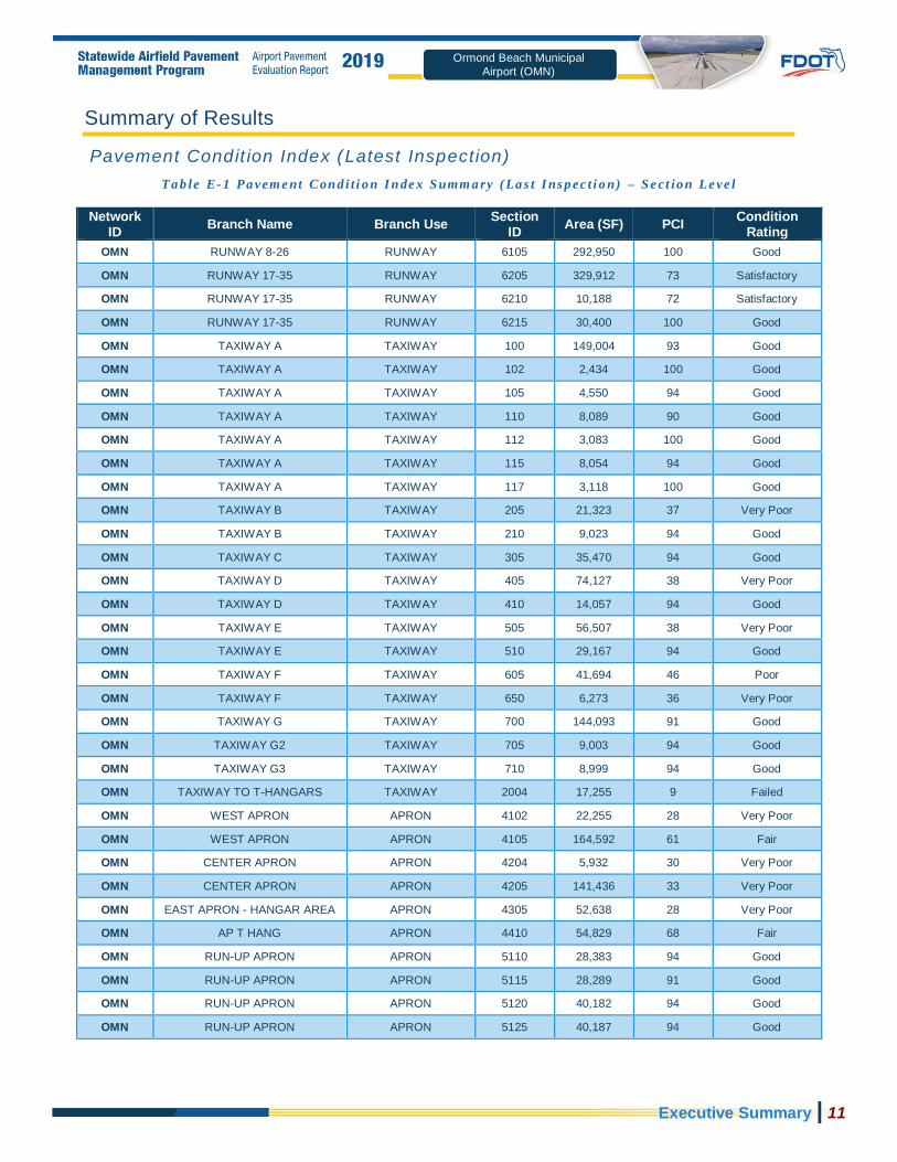
Pavement Condit ion Index (Latest Inspection)
Ta b le E- 1 Pa vem e nt Con d i t i o n I n de x S umm a ry ( La s t I ns p ec t i o n) – S e c t io n Le ve l
Network ID
Branch Name Branch Use Section
ID Area (SF) PCI
Condition Rating
OMN RUNWAY 8-26 RUNWAY 6105 292,950 100 Good
OMN RUNWAY 17-35 RUNWAY 6205 329,912 73 Satisfactory
OMN RUNWAY 17-35 RUNWAY 6210 10,188 72 Satisfactory
OMN RUNWAY 17-35 RUNWAY 6215 30,400 100 Good
OMN TAXIWAY A TAXIWAY 100 149,004 93 Good
OMN TAXIWAY A TAXIWAY 102 2,434 100 Good
OMN TAXIWAY A TAXIWAY 105 4,550 94 Good
OMN TAXIWAY A TAXIWAY 110 8,089 90 Good
OMN TAXIWAY A TAXIWAY 112 3,083 100 Good
OMN TAXIWAY A TAXIWAY 115 8,054 94 Good
OMN TAXIWAY A TAXIWAY 117 3,118 100 Good
OMN TAXIWAY B TAXIWAY 205 21,323 37 Very Poor
OMN TAXIWAY B TAXIWAY 210 9,023 94 Good
OMN TAXIWAY C TAXIWAY 305 35,470 94 Good
OMN TAXIWAY D TAXIWAY 405 74,127 38 Very Poor
OMN TAXIWAY D TAXIWAY 410 14,057 94 Good
OMN TAXIWAY E TAXIWAY 505 56,507 38 Very Poor
OMN TAXIWAY E TAXIWAY 510 29,167 94 Good
OMN TAXIWAY F TAXIWAY 605 41,694 46 Poor
OMN TAXIWAY F TAXIWAY 650 6,273 36 Very Poor
OMN TAXIWAY G TAXIWAY 700 144,093 91 Good
OMN TAXIWAY G2 TAXIWAY 705 9,003 94 Good
OMN TAXIWAY G3 TAXIWAY 710 8,999 94 Good
OMN TAXIWAY TO T-HANGARS TAXIWAY 2004 17,255 9 Failed
OMN WEST APRON APRON 4102 22,255 28 Very Poor
OMN WEST APRON APRON 4105 164,592 61 Fair
OMN CENTER APRON APRON 4204 5,932 30 Very Poor
OMN CENTER APRON APRON 4205 141,436 33 Very Poor
OMN EAST APRON - HANGAR AREA APRON 4305 52,638 28 Very Poor
OMN AP T HANG APRON 4410 54,829 68 Fair
OMN RUN-UP APRON APRON 5110 28,383 94 Good
OMN RUN-UP APRON APRON 5115 28,289 91 Good
OMN RUN-UP APRON APRON 5120 40,182 94 Good
OMN RUN-UP APRON APRON 5125 40,187 94 Good

Executive Summary | 12
Ormond Beach Municipal
Airport (OMN)
Forecasted Pavement Condit ion Index 2020-2029
Ta b le E- 2 Pa vem e nt Con d i t i o n I n de x Fo re c as t 2 020 - 2 02 9
Network ID
Branch ID Section
ID Last PCI
Forecasted PCI
2020 2021 2022 2023 2024 2025 2026 2027 2028 2029
OMN AP CENTER 4204 30 29 29 29 28 28 28 27 27 27 26
OMN AP CENTER 4205 33 30 28 26 24 22 20 17 15 13 11
OMN AP E 4305 28 27 27 26 26 26 25 25 25 24 24
OMN AP RU 5110 94 91 89 87 85 82 80 78 76 74 73
OMN AP RU 5115 91 88 86 84 82 80 78 76 74 72 70
OMN AP RU 5120 94 91 89 87 85 82 80 78 76 74 73
OMN AP RU 5125 94 91 89 87 85 82 80 78 76 74 73
OMN AP T HANG 4410 68 66 65 64 63 62 61 60 59 58 57
OMN AP W 4102 28 27 27 26 26 26 25 25 25 24 24
OMN AP W 4105 61 60 59 58 57 56 56 55 54 54 53
OMN RW 17-35 6205 73 71 70 69 68 67 66 65 65 64 63
OMN RW 17-35 6210 72 70 69 68 67 66 66 65 64 63 62
OMN RW 17-35 6215 100 98 96 93 91 89 87 85 82 81 79
OMN RW 8-26 6105 100 98 96 93 91 89 87 85 82 81 79
OMN TW A 100 93 91 89 88 86 85 83 82 80 79 77
OMN TW A 102 100 98 96 94 93 91 89 88 86 85 83
OMN TW A 105 94 91 89 87 85 84 82 80 79 77 76
OMN TW A 110 90 88 86 85 83 82 80 79 77 76 75
OMN TW A 112 100 98 96 94 93 91 89 88 86 85 83
OMN TW A 115 94 92 90 89 87 86 84 83 81 80 78
OMN TW A 117 100 98 96 94 93 91 89 88 86 85 83
OMN TW B 205 37 35 33 31 29 27 25 23 21 19 17
OMN TW B 210 94 92 90 89 87 86 84 83 81 80 78
OMN TW C 305 94 92 90 89 87 86 84 83 81 80 78
OMN TW D 405 38 36 34 32 30 28 26 24 22 20 18
OMN TW D 410 94 92 90 89 87 86 84 83 81 80 78
OMN TW E 505 38 36 34 32 30 28 26 24 22 20 18
OMN TW E 510 94 92 90 89 87 86 84 83 81 80 78
OMN TW F 605 46 45 44 43 43 42 41 41 40 40 39
OMN TW F 650 36 35 35 35 34 34 34 34 34 33 33
OMN TW G 700 91 89 87 86 84 83 81 80 78 77 76
OMN TW G2 705 94 92 90 89 87 86 84 83 81 80 78
OMN TW G3 710 94 92 90 89 87 86 84 83 81 80 78
OMN TW T-HANG 2004 9 7 6 5 4 3 2 1 0 0 0

Executive Summary | 13
Ormond Beach Municipal
Airport (OMN)
Major Rehabil itat ion Planning 2020-2029
Ta b le E- 3 M aj or Re h a bi l i t a t i on Pl a n ni n g 20 2 0- 2 02 9
Program Year
Network ID
Branch ID Section
ID Surface
Area (SF)
PCI Before
Rehabilitation Type
Planning Cost
2020 OMN AP CENTER 4204 AC 5,932 29 AC Reconstruction $ 75,000.00
2020 OMN AP CENTER 4205 AAC 141,436 30 AC Reconstruction $ 1,768,000.00
2020 OMN AP E 4305 AC 52,638 27 AC Reconstruction $ 658,000.00
2020 OMN AP W 4102 AC 22,255 27 AC Reconstruction $ 279,000.00
2020 OMN AP W 4105 AC 164,592 60 AC Restoration $ 1,564,000.00
2020 OMN TW B 205 AAC 21,323 35 AC Reconstruction $ 267,000.00
2020 OMN TW D 405 AAC 74,127 36 AC Reconstruction $ 927,000.00
2020 OMN TW E 505 AAC 56,507 36 AC Reconstruction $ 707,000.00
2020 OMN TW F 605 AC 41,694 45 AC Restoration $ 455,000.00
2020 OMN TW F 650 AC 6,273 35 AC Reconstruction $ 79,000.00
2020 OMN TW T-HANG 2004 PCC 17,255 7 PCC Reconstruction $ 346,000.00
2022 OMN AP T HANG 4410 AC 54,829 64 AC Restoration $ 521,000.00
2027 OMN RW 17-35 6210 AAC 10,188 64 AC Restoration $ 97,000.00
2028 OMN RW 17-35 6205 AAC 329,912 64 AC Restoration $ 3,135,000.00
*All planning cost values have been rounded to the nearest thousand-dollar.
Fi g u re E- 4 Ma jo r Re h ab i l i t a t io n Pl a nn i ng An nu a l Bu d ge t 2 02 0 -2 0 2 9
$7,125,000
$-
$521,000
$- $- $- $- $97,000
$3,135,000
$- $-
$1,000,000
$2,000,000
$3,000,000
$4,000,000
$5,000,000
$6,000,000
$7,000,000
$8,000,000
2020 2021 2022 2023 2024 2025 2026 2027 2028 2029
Major Rehabilitation Needs by Program Year

Executive Summary | 14
Ormond Beach Municipal
Airport (OMN)
Summary of Ormond Beach Municipal Airport
Ormond Beach Municipal Airport was inspected in January of 2019 – the overall weighted PCI
value was 73, a condition rating of Satisfactory. The results of the maintenance, repair, and
major rehabilitation analysis identified $1,115,890 in localized M&R needs based on current
conditions and a 10-Year major rehabilitation need of $10,878,000 based on forecasted
conditions. The current major rehabilitation needs based on the latest inspection consist of
$7,125,000 for pavements below critical condition.
Localized maintenance and repair identified within this report are categorized as preventive or
stopgap; the FDOT SAPMP has defined maintenance policies based on FAA recommendations.
Major rehabilitation is identified within the FDOT SAPMP as major construction activity that
would result in an improvement or resetting of the pavement section’s PCI to a value of 100.
Such activities could include: mill and hot-mix asphalt overlay, rigid pavement repair and slab
replacement, and full-depth reconstruction. It is recommended that the airport use this as a
planning tool for future project development and prioritization – all localized maintenance and
repair and major rehabilitation recommendations should be considered as planning-level only.
All final localized maintenance, repair, and major rehabilitation is subject to change based on
airport prioritization and further design-level evaluation.

Chapter 1

Chapter 1 – Introduction | 16
Ormond Beach Municipal
Airport (OMN)
Chapter 1 – Introduction
1.1 Background
The State of Florida has 128 public airports of which 100 public-use airports are recognized as
part of the Federal Aviation Administration’s (FAA) National Plan of Integrated Airport Systems
(NPIAS) that are vital to the Florida economy as well as the economy of the United States. The
Florida Aviation System (FAS) provides opportunities for the State to capitalize on an
increasingly global marketplace. Florida’s system of commercial service and general aviation
(GA) airports are important to businesses throughout the entire State. Air travel is essential to
tourism, Florida’s number one industry.
There are millions of square feet of pavement infrastructure that consists of runways, taxiways,
aprons, ramps, and other areas of airports that are vital to the support and safety of aircraft
operations. Timely pavement maintenance, repair and major rehabilitation of these pavements
will support the airport in operating safely, efficiently, economically and without excessive down
time.
In general, adherence to the FAA Advisory Circulars are mandatory for all projects funded with
federal grant monies through the Airport Improvement Program (AIP) and with revenue from the
Passenger Facilities Charges (PFC) Program. Further information is detailed in FAA Grant
Assurance No. 11 “Pavement Maintenance,” No. 34 “Policies, Standards, and Specifications,”
and PFC Assurance No. 9 “Standards and Specifications.” The Florida Department of
Transportation (FDOT) performs the Statewide Airfield Pavement Management Program
(SAPMP) System Updates for the benefit of participating public-use and publicly owned airports
through the Aviation and Spaceports Office (ASO).
The SAPMP addresses the requirements of maintaining an effective pavement management
program for the participating airports at the network level. Network-level management of
pavement assets provides insight for short-term and long-term budget needs, understanding of
the overall condition of the network (current and future), and pavement facilities that are subject
for project consideration. A network-level evaluation can be supportive in the identification of
maintenance, repair, and major rehabilitation needs and budgetary planning-level opinions of
probable construction costs.
1.2 Statewide Airfield Pavement Management Program (SAPMP) Update
2018-2019
In 1992, the FDOT established the Statewide Airfield Pavement Management Program
(SAPMP) to provide program managers, District Aviation and Spaceport Offices, and airport
operators a system to proactively manage airport airfield pavement infrastructure within the
Florida Aviation System. The SAPMP performs network-level Pavement Condition Index (PCI)
survey inspections for airport facilities that are categorized as General Aviation (GA), Reliever
(RL), and Commercial (PR). Currently, the program consists of 95 actively participating public-
use airports with pavement facilities and provides users with comprehensive data to better
manage pavement assets.
Chapter 1 – Introduction | 17
Ormond Beach Municipal
Airport (OMN)
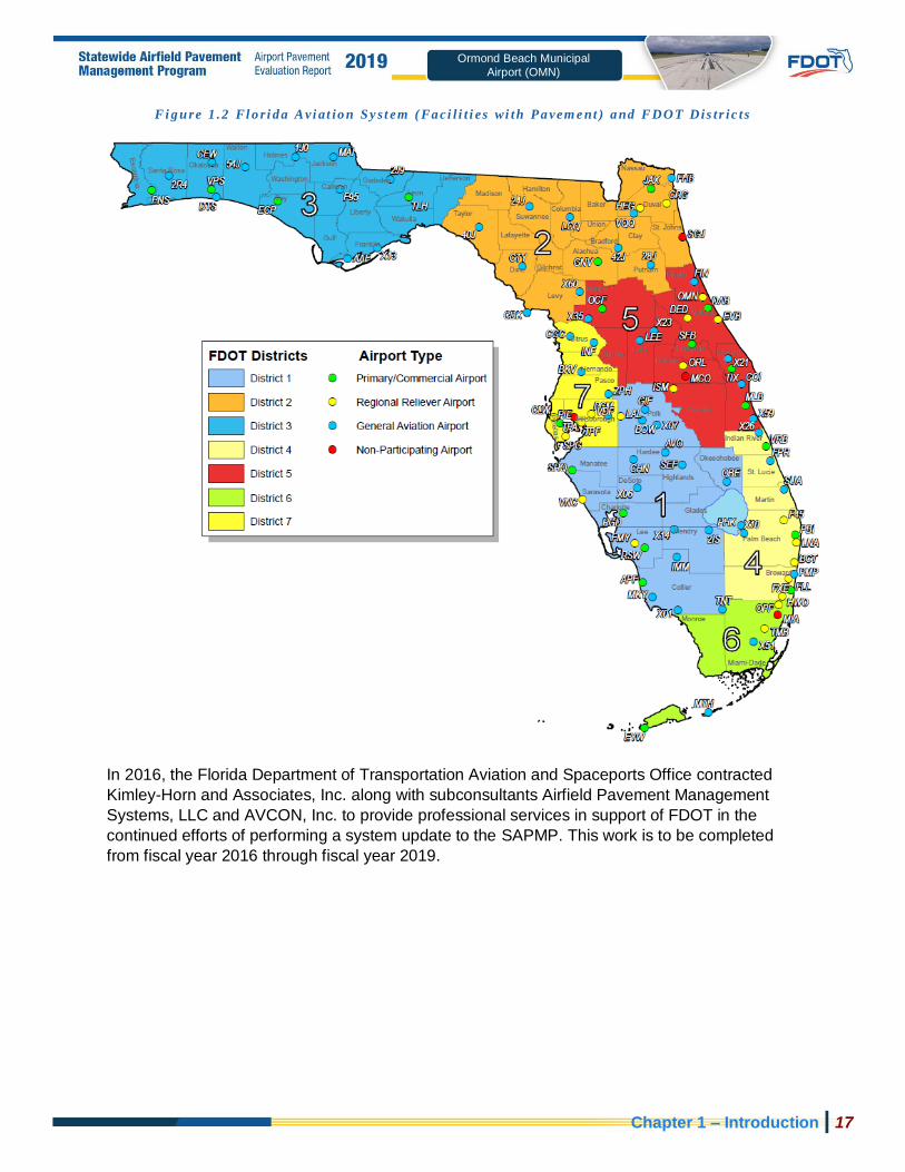
Fi g u re 1 .2 Fl o r i d a Avi at io n S y s t em ( Fa ci l i t i es wi th Pa vem e nt ) a nd FDOT Dis t r i c t s
In 2016, the Florida Department of Transportation Aviation and Spaceports Office contracted
Kimley-Horn and Associates, Inc. along with subconsultants Airfield Pavement Management
Systems, LLC and AVCON, Inc. to provide professional services in support of FDOT in the
continued efforts of performing a system update to the SAPMP. This work is to be completed
from fiscal year 2016 through fiscal year 2019.

Chapter 1 – Introduction | 18
Ormond Beach Municipal
Airport (OMN)
1.3 Organization
1.3.1 Florida Department of Transportation Aviat ion and Spaceports
Office Program Manager
The FDOT Aviation and Spaceports Office (ASO) Aviation Engineering Manager serves as the
Program Manager (ASO-PM) for the SAPMP. The ASO-PM monitors the work performed by the
designated Consultant for the program. The ASO-PM has review and approval authority for
each program task and manages the program’s day-to-day details and pertinent updates.
The ASO-PM reports updates and milestones to the FDOT State Aviation and Spaceports
Manager and Development Administrator.
1.3.2 Part ic ipat ing Flor ida Publ ic -Use and Publ ic ly Owned Airports
The airports are the end-user and beneficiary of the SAPMP. The SAPMP provides a specific
Airport Pavement Evaluation Report that meets the requirements of the FAA Advisory Circular
150/5380-7B “Airport Pavement Management Program (PMP) .” Individual participating
airports will be provided a final Airport Pavement Evaluation Report by the designated
Consultant that is specific to each airport’s airfield pavement condition index survey. The ASO-
PM has full authority and final approval of each report prior to finalization. In advance of each
PCI survey and prior to completion of each Airport Pavement Evaluation Report, participating
airports are asked to provide the necessary record documentation for the proper analysis
efforts. Relevant record documentation artifacts may consist of but are not limited to: Airport
Layout Plans (ALP), Construction Bid Tabulations, As-Built Construction Drawings, Engineer’s
Reports, and/or field pavement inspection reports.
1.3.3 Florida Department of Transporta tion Distr ict Off ices
The seven (7) FDOT District Offices, specifically the Aviation representatives (currently the
Freight and Logistics personnel), provide essential support to the SAPMP update and the ASO-
PM. Each District supports the SAPMP’s on-going efforts by providing local construction cost
information throughout the State. The construction cost information, typically consisting of plans
and bid tabulations, are used as the basis of the development maintenance, repair, and major
rehabilitation opinions of probable construction costs for planning purposes. Each District Office
receives copies of individual Airport Pavement Evaluation Reports for the participating airport
facilities located within their respective Districts.
1.3.4 Consultant
The Consultant, Kimley-Horn and Associates, Inc., provides technical and administrative
support to the ASO-PM for the SAPMP update. The support consists of airfield pavement
system inventory updates, performance of PCI Surveys in accordance with ASTM D5340-12
“Standard Test Method for Airport Pavement Condition Index Surveys,” evaluation and
reporting of the pavement condition in accordance with the FAA Advisory Circular 150/5380-7B
“Airport Pavement Management Program (PMP) .”
The Consultant Team consists of Kimley-Horn, Airfield Pavement Management Systems, LLC.,
and AVCON, Inc.

Chapter 1 – Introduction | 19
Ormond Beach Municipal
Airport (OMN)
A brief description of the general scope of work undertaken to update the SAPMP includes but
is not limited to:
Research and evaluation of existing record documentation was performed to
identify construction projects that have taken place since the most recent major update
of the SAPMP. This data is used to update the pavement inventory and network
definition.
An update to the existing Network Definition Map was made to reflect geometric
changes, pavement composition updates, and section characterization. Furthermore, an
update to the PCI Survey sample units were made to reflect the field investigation
efforts.
A functional pavement evaluation with PCI Survey inspections was completed on all
airfield pavements maintained by the Airport. The PCI Survey procedure, as defined by
ASTM D5340-12, was used as the basis of the functional pavement evaluation. For this
specific evaluation, the sample units defined by prior studies were inspected as to better
develop performance models for prediction curves. Pavement subject to construction or
anticipated construction during scheduled PCI Survey inspection or within 2 years were
omitted from inspection based on confirmation of airport personnel.
Condition Analysis was performed based on the distress data observed, rated,
measured, and recorded in accordance with the ASTM D5340-12 for the calculation of
PCI values and ratings. The results of the current condition analysis were used in
concert with the historic PCI Survey data and construction work history to develop
performance models to forecast future PCI values for each section for a 10-year study
duration.
Maintenance, Repair, and Rehabilitation Planning was performed predicated on the
results of the condition analysis with updated policies and planning-level unit costs. The
policies, or M&R policies, have been updated to reflect standard practices for
maintenance, repair, and major rehabilitation as defined by the FAA AC 150/5380-6C
“Guidelines and Procedures for Maintenance of Airport Pavements.” Planning-
level unit costs were developed based on representative construction bid tabulations
provided by participating airports. The bid tabulations consisted of limited airfield
pavement construction projects that took place between 2009 and 2015 at participating
airports.

Chapter 1 – Introduction | 20
Ormond Beach Municipal
Airport (OMN)
1.4 Purpose of Airport Pavement Evaluation Report
The individual airport airfield pavement evaluation report discusses the work performed, a
summary of findings, condition analysis results, and recommendations for maintenance, repair,
and major rehabilitation (M&R) planning associated with the SAPMP system update. It also
briefly describes the procedures used to ensure that the appropriate engineering and scientific
standards of care, quality, budget, schedules, and safety requirements were implemented
during the performance of this work.
The purpose of this Airfield Pavement Evaluation Report is to achieve the following:
• Describe the goals, procedures, and purpose of the SAPMP
• Provide a brief technical explanation of the pavement management methodology,
standard practices, and objectives
• Analyze pavement distresses data for the determination of pavement conditions and for
identification of airfield pavement maintenance, repair, and major rehabilitation needs
based on functional PCI trends
The identification of rehabilitation needs has been determined at the planning level.
Design-level investigation is recommended prior to developing construction-level design
documents and budgets.
In compliance with FAA Grant Assurances 11 and 19; the FDOT SAPMP provides airports with
airfield pavement evaluation reports in accordance with FAA AC 150/5380-7B Airport
Pavement Management Program (PMP) and AC 150/5380-6C Guidelines and Procedures
for Maintenance of Airport Pavements. The application of the results of a PCI survey are for
planning purposes and are limited to the visual observation of deteriorated pavements in limited
sampling; design-level investigation is recommended in accordance with the FAA procedures
defined in AC 5320-6F Airport Pavement Design and Evaluation and AC 150/5370-11B Use
of Nondestructive Testing in the Evaluation of Airport Pavements. The aforementioned
ACs provide the design-level material properties of in-situ pavement and subgrade layers for the
determination of appropriate rehabilitation actions. The FDOT Statewide Airfield Pavement
Management Program is organized to provide airports with planning-level data and does not
intend to preclude the responsible engineer in performing the appropriate level of investigation
and analysis in determining the appropriate design details of a pavement rehabilitation. It would
not be advisable to solely base design-level rehabilitation without the appropriate level of
investigation and determination of pavement deterioration beyond that of a visual functional
condition assessment.
1.5 History of the Program
In 1992, the FDOT implemented the SAPMP to understand the pavement conditions at public
airports in the FAS, systematically update pavement infrastructure information, and assist
airport operators with recommendations of pavement maintenance, repair, and major
rehabilitation needs. The 1992 SAPMP implementation provided the FDOT and the participating
airports valuable information for establishing and performing timely and appropriate pavement
rehabilitation.

Chapter 1 – Introduction | 21
Ormond Beach Municipal
Airport (OMN)
During the 1992-1993 implementation and again during the 1998-1999 updates; the SAPMP
performed the development with proprietary software for pavement management system
analysis. This development allowed for the creation of pavement management database file
system populated with airport attributes and condition data. The pavement management
database was used to establish maintenance, repair, and rehabilitation policies; consider
planning-level unit costs; and develop recommendations for performing pavement maintenance.
This system, known as AIRPAV, was initially developed during the 1992-1993 SAPMP
implementation for the analysis of distress data. The AIRPAV system was used again in the
1998-1999 SAPMP update.
In 2004, the SAPMP system update included the review of the AIRPAV software compared to
other industry available non-proprietary software packages. As a result of this review,
MicroPAVERTM (currently known as PAVERTM) was selected for implementation of the system
update. MicroPAVERTM was developed by the U.S. Army Corps of Engineers Construction
Engineering Research Laboratory for pavement management. Data from the 1998-1999 FDOT
SAPMP update, which was built upon the initial 1992-1993 implementation of AIRPAV, was
reviewed and converted to be compatible with the MicroPAVERTM system. This data conversion
included all documented pavement facilities, classifications, types, histories, geometries, PCI
condition data and pertinent attributes gathered from airport feedback at the time. This
information was used to develop the inventory of each participating airport’s pavement facilities
in a consistent format. This was the development of Airfield Pavement Network Definition
Exhibits. These inventory exhibits visually depicted the branch, section, and sample units that
were based upon the pavement construction history and composition information provided by
each airport.
In the 2006-2008 system update, the SAPMP was updated again with continued use of the
MicroPAVERTM system. Based on the distress data collected, a maintenance repair and major
rehabilitation planning program was developed for each airport. As part of this SAPMP update,
the procedures for the inspection and the collection of the pavement distress data were
documented, and an interactive website (http://www.dot.state.fl.us/aviation/pavement.shtm) was
established for input of data.
In the 2010-2012 system update, the SAPMP was updated using new global positioning system
(GPS) integrated technology to digitally collect pavement distress data. Interactive geographic
information system (GIS) map files were developed from updated Airfield Pavement Network
Definition Exhibits to aid pavement condition inspectors in the collection of sample distress data.
The data collected was utilized to develop pavement performance models to predict future
pavement PCI values and make recommendations for major rehabilitation.
In the 2013-2015 system update, the SAPMP integrated PAVERTM and FieldInspectorTM with the
use of GPS and GIS capable field tablets. Furthermore, the update included continued
adherence to the ASTM D5340-12 “Standard Test Method for Airport Pavement
Condition Index Surveys.” The ASTM update consisted of refinement of distress definition
types and deduction values for select asphalt concrete and Portland Cement Concrete
distresses.

Chapter 1 – Introduction | 22
Ormond Beach Municipal
Airport (OMN)
1.6 Federal Aviation Administration (FAA)
Currently, airports participating in the Airport Improvement Program (AIP) Grant Program are
required by the FAA to develop and implement a pavement maintenance program to be eligible
for funding (FAA Advisory Circular 150/5380-6C “Guidelines and Procedures for
Maintenance of Airport Pavements” and 150/5380-7B “Airport Pavement Management
Program (PMP)”). This program requires detailed inspection of airfield pavement conditions by
trained personnel. The inspections are required to be performed at least once a year using the
PASER method or every three years if the pavement is inspected as defined by the PCI survey
procedure in accordance with the ASTM D5340-12 “Standard Test Method for Airport
Pavement Condition Index Surveys.”
In general, adherence to the Advisory Circulars are mandatory for all projects funded with
federal grant monies through the AIP program and with revenue from the Passenger Facilities
Charges (PFC) Program. Further information is detailed in FAA Grant Assurance No. 11
“Pavement Maintenance,” No. 34 “Policies, Standards, and Specifications,” and PFC Assurance
No. 9 “Standards and Specifications.”
1.7 FDOT SAPMP Objectives and Components
The FDOT SAPMP is a program that provides the FAS support in implementing and/or
maintaining a network-level Pavement Management Program in a consistent and regularly
scheduled manner.
In accordance with FAA AC150/5380-7B “Airport Pavement Management Program
(PMP)” an effective Pavement Management Program consists of a system that achieves
specific objectives. The FDOT SAPMP objectives are as follows:
1.7.1 Program Object ives
1 A systematic means for collecting and storing information regarding existing pavement
structure and condition.
2 An objective and repeatable system for evaluating pavement condition.
3 Procedures for predicting future pavement condition.
4 Procedures for modeling both past and future pavement performance conditions.
5 Procedures to determine the budget requirements to meet management objectives, such as
the maintenance, repair, and major rehabilitation budget required to keep a pavement at a
specified PCI level or the budget required to improve to target PCI level.
6 Procedures for formulating and prioritizing maintenance, repair, and major rehabilitation
projects.
The objectives are accomplished by the following components:
1.7.2 Program Components
A. Database
B. Pavement Inventory
C. Pavement Structure
D. Pavement Work History
E. Pavement Condition Data

Chapter 1 – Introduction | 23
Ormond Beach Municipal
Airport (OMN)
F. Pavement Performance Modeling for the Prediction/Forecast of PCI
G. Maintenance, Repair, and Major Rehabilitation Policies and Budget Simulation
A well-maintained network-level pavement management program may provide airport staff a
better understanding of the airfield pavement performance for developing and planning for
specific maintenance, repair, and major rehabilitation projects. The understanding of specific
distress types and severities will assist the airport in addressing pavement maintenance and
repair with the appropriate treatments as defined by the FAA Advisory Circular 150/5380-6C
“Guidelines and Procedures for Maintenance of Airport Pavements.” The development
of projects with an understanding of system inventory, deterioration details, and pavement
condition forecasts may assist airport staff in developing practical rehabilitation actions and
budgets. Furthermore, the understanding of pavements’ past performance and forecasted
condition may assist airport staff in addressing pavement rehabilitation in a timely and cost-
effective manner. Figure 1.7.2 (a) Typical Pavement Condition Life Cycle, which is based on
the FAA Advisory Circular 150/5380-7B “Airport Pavement Management Program
(PMP).” Figure 1.7.2 (a) Typical Pavement Condition Life Cycle, depicts a general duration
of a pavement section and identifies the ideal condition to perform rehabilitative treatments at an
optimal cost rather than allowing significant increase in rate of deterioration that would result in
increased costs.
Fi g u re 1 .7 . 2 ( a ) Typ ic a l Pav em e nt Co n di t i o n Li fe Cy c le
*Figure is for conceptual purposes only – unit costs are not specific to airfield pavements (AC vs PCC).
Figure 1.7.2 (b) General Pavement Treatments by Condition Range depicts generic flexible
asphalt concrete (AC) pavement treatments that are effective at specific condition ranges. This
graphic is a general concept and will vary based on pavement surface type and overall

Chapter 1 – Introduction | 24
Ormond Beach Municipal
Airport (OMN)
composition. The intent is to convey various treatment types that would be effective based on
the condition of the pavement along the deterioration model.
Fi g u re 1 .7 . 2 ( b ) Ge ne r al Pa vem e nt Tr e atm e nt s by Co n d i t io n Ra n g e
Pavement maintenance, repair, and major rehabilitation would be quite anticipatory if all
pavements behaved as depicted in Figures 1.7.2 (a) and 1.7.2 (b), however pavement
condition performance vary significantly based on several factors. Factors that contribute to a
pavement section’s condition and deterioration performance may include: functional design life,
material type, material construction quality, climatic conditions, aircraft loading type and
frequency, non-aircraft loading type and frequency, maintenance history, subgrade conditions,
and other infrastructure in the vicinity. The list of factors is not all-inclusive of all factors that may
contribute to a pavement’s life cycle, it is intended to clarify that unique conditions certainly will
affect a pavement’s deterioration.
Figures 1.7.2 (c) and 1.7.2 (d), depict visual conditions of pavement facilities, for both AC and
PCC respectively, with approximated PCI ranges and corresponding repair and rehabilitation
measures.

Chapter 1 – Introduction | 25
Ormond Beach Municipal
Airport (OMN)
Fi g u re s 1 . 7 . 2 ( c) Fl ex i bl e Asp h al t Co nc r e t e
Fi g u re s 1 . 7 . 2 ( d) Ri gi d Po r t l a n d Cem en t Co nc r e t e

Chapter 1 – Introduction | 26
Ormond Beach Municipal
Airport (OMN)
1.8 References
The following reference documents were referenced as specific guidelines and procedures for
maintaining airport pavements; establishing an effective pavement maintenance program; and
identifying specific pavement distresses, probable causes of distresses, inspection guidelines,
and recommended methods of repair:
• ASTM D5340-12 “Standard Test Method for Airport Pavement Condition Index Surveys.”
• FAA Advisory Circular 150/5380-7B “Airport Pavement Management Program.”
• FAA Advisory Circular 150/5380-6C “Guidelines and Procedures for Maintenance of
Airport Pavements.”
• FAA Advisory Circular 150/5320-6F “Airport Pavement Design and Evaluation.”
• Department of the Air Force, Air Force Civil Engineer Center “Engineering Technical
Letter (ETL) 14-3: Preventive Maintenance Plan (PMP) for Airfield Pavements.”
• Unified Facilities Criteria (UFC) 3-260-16FA 16 “Airfield Pavement Condition Survey
Procedures Pavements.”
• Unified Facilities Criteria (UFC) 3-260-03 “Airfield Pavement Evaluation.”
• Pavement Management for Airports, Roads, and Parking Lots 2nd Edition, M.Y. Shahin.

Chapter 2

Chapter 2 – Methodology | 28
Ormond Beach Municipal
Airport (OMN)
Chapter 2 – Methodology An effective pavement management program incorporates the regular collection of pavement
condition information and communication of information to appropriate sponsors. This chapter of
the report defines the specific methods utilized as part of the SAPMP System Update to meet
the requirements of an effective pavement management system as defined by the FAA Advisory
Circular 150/5380-7B “Airport Pavement Management Program (PMP).”
2.1 Airfield Pavement Database
The SAPMP program has historically utilized PAVERTM (formerly MicroPAVERTM); the current
update has maintained the use of the PAVERTM 7.0 version of the software. The PAVERTM
software application was developed by the U.S. Army Construction Engineering Research
Laboratory sponsored by the FAA, Federal Highway Administration, U.S. Army, U.S. Air Force,
and the U.S. Navy to meet the objectives of an effective pavement management system. The
SAPMP consists of a network-level database of the airport’s airfield pavement facilities that are
part of the program. PAVERTM can achieve the following pavement management objectives: a
manageable inventory system, the analysis of the current condition of pavements in accordance
with the ASTM D5340, the development of pavement performance models to forecast
conditions, and the development of maintenance, repair, and major rehabilitation
recommendations based on budgetary scenarios.
PAVERTM inventory management is based on a tiered organizational structure that consists of
networks, branches, and sections, with the section being the smallest unit of management.
Critical elements of an effective pavement management program are maintained within the
network-level PAVERTM database. These elements typically consist of pavement inventory
characteristics, pavement structure, work history, historic condition records, and analytical
customization.
The SAPMP System Update consisted of the conversion of the previous database from a
PAVERTM version 6.5 to a version 7.0.
2.2 Airfield Pavement System Inventory
An airfield pavement system inventory typically maintains the location of all runways, taxiways,
and aprons; geometric characteristics; type of pavement structure, year of construction and/or
last major rehabilitation; and general composition details of the pavement.
The pavement inventory for an airport’s airfield is an assembly of pavement infrastructure
information that builds an inventory of branches and sections that codifies the airport’s airfield
pavement network. General geometry characteristics, estimated length, width, functional
classification, pavement surface type, and operational function are among the characteristics
identified at this initial phase in the pavement management process. The development of a
pavement inventory that reasonably reflects the airport’s airfield pavement facilities that are
maintained by the airport provides a defined scope of the inspection and analysis efforts. As in
the past, the SAPMP scope of work is specific to the airport-maintained airfield pavements as
defined in the field network definition exhibits presented to current airport personnel.

Chapter 2 – Methodology | 29
Ormond Beach Municipal
Airport (OMN)
A critical input to the pavement system inventory and network definition in the development of
the SAPMP update is the date of last major rehabilitation/construction performed on the
pavement assets that would set the asset at a PCI of 100 and a condition rating of Good. The
airport provided a limited combination of record drawings, reports, and staff input that was
pertinent information in developing the construction history of the airport’s pavements from
inception. Major rehabilitation/construction activities performed in the last 24-months or
anticipated in the next 24-months are assumed to restore the PCI to 100. These activities
include; pavement overlay, mill and replace, mill and overlay, new construction, and/or complete
reconstruction.
Aerial imagery was obtained through the FDOT Surveying & Mapping Office’s Aerial Photo Look
Up System (APLUS). This spatially projected imagery was utilized with computer-aided drafting
software (AutoCAD) in concert with geographical information system software (ArcGIS) to
develop a planning-level representative model that reasonably reflects the pavement assets at
the airport.
2.2.1 Pavement Management Program Network Def in it ion Terminology
There are several terms that are common in the communication of the results of the SAPMP
System Update, these terms are defined as follows:
Pavement Network
A pavement network is a logical unit for organizing pavements into a structure for pavement
management. A network will typically consist of one or more pavement branches, which are
typically comprised of one or many pavement sections. The network is the starting point of the
hierarchy of pavement management organization. For example, a network can be all the
pavements within an airport’s airfield or all the pavements in a statewide program. For the
FDOT SAPMP, a network represents an individual airport’s airfield pavement facilities
maintained by the airport.
The SAPMP System Update consists of research and evaluation of existing record
documentation for the participating airports’ airfield facilities. The pavement network is typically
limited to the pavement facilities subject to aircraft use that is also maintained by the airport
owner and eligible for public funding.
Pavement Branch
A pavement branch, also known as a facility, is a logical unit of generally identifiable pavement
of a network with distinct functional classification. For example, within an airfield each runway,
taxiway, or apron is considered a branch. A branch must consist of at least one section.
Pavement Section
A pavement section, also known as a feature, is the most specific management unit when
considering the application and selection of maintenance, repair, and/or major rehabilitation
treatments on an area of pavement within a branch. Each branch consists of at least one
section, but may consist of more if pavement feature characteristics are distinct throughout the
branch. Characteristics considered when subdividing branches into sections include, but are not
limited to: pavement structure, type, age, condition, and function; traffic composition and
frequency (current and future); geometric location; construction history; and other related

Chapter 2 – Methodology | 30
Ormond Beach Municipal
Airport (OMN)
infrastructure features (e.g. drainage). A pavement section is defined as a subordinate of a
pavement branch, which is a subordinate of a “parent” pavement network.
Pavement Sample Unit
A pavement sample unit is a subdivision of a pavement section that has a standard size range:
twenty (20) continuous slabs (±8 slabs) for Portland Cement Concrete (PCC) pavement and
5,000 contiguous square feet (±2,000 ft2) for flexible asphalt concrete (AC) or porous friction
course pavements.
Ta b le 2 . 2 . 1 A ir f i e l d Pa vem e nt Da t ab a se Ne t wor k De f in i t io n Te rm in ol o g y
PMS Network Level Common Definition Airport Example
Network Overall pavement assets maintained by the Airport
“Tallahassee International Airport – Airfield Pavements”
Branch Name Commonly defined asset name as established by Airport and by use
“Runway 18-36”
Branch ID Codified shorthand name for commonly defined asset established for database identification
“RW 18-36”
RW, Branch Use, “Runway”
18-36, Runway Facility
Section ID
Codified identification for pavement asset that is distinct by the following:
• Pavement Composition
• Construction Work History
• Aircraft Traffic
• Condition Records
“6105”
Sample Unit
A numeric identification of an area of pavement (5,000±2,000 SF of AC or 20±8 slabs of PCC) that has been
inspected in accordance with ASTM D5340-12.
“300”

Chapter 2 – Methodology | 31
Ormond Beach Municipal
Airport (OMN)
2.3 Airfield Pavement Structure
2.3.1 Pavement Structure Types
Airport airfield pavements are constructed to provide adequate support for the loads imposed by
aircraft and produce a firm, stable, smooth, all-year, all-weather surface free of debris or other
particles that may be blown or dislocated by propeller wash or jet blast. Typical pavement
planning and design requires coordination of factors that include but are not limited to; subgrade
conditions, material layer types, aircraft fleet mix (type, frequency, and traffic growth), and
functional use. A pavement structure is composed of constructed layers that consist of
subgrade, subbase, base course, structural courses, and surfaces courses. For the FDOT
SAPMP, two major pavement structure types are classified for evaluation and analysis: Flexible
Asphalt Concrete Surface and Rigid Portland Cement Concrete Surface. Additionally,
Composite Structures known as Whitetopping Pavements are also present at limited airports
within the Florida Airports System; these unique pavement structures are evaluated separately.
Flexible Asphalt Concrete Surface
A pavement comprised of aggregate mixture with an asphalt cement binder. The FDOT SAPMP
consists of three (3) asphalt concrete surface types: Asphalt Concrete (AC), Asphalt Concrete
Overlaid on Asphalt Concrete (AAC), and Asphalt Concrete Overlaid on Portland Cement
Concrete (APC).
Asphalt Concrete (AC)
A flexible pavement section consisting of aggregate mixture with asphalt cement binder
layered on engineered base course material that is layered on subbase and subgrade
soil material.
Asphalt Concrete Overlaid on Asphalt Concrete (AAC)
A flexible pavement section consisting of aggregate mixture with asphalt cement binder
layered on an existing flexible AC pavement section. Flexible airfield pavement sections
are AAC when a pavement rehabilitation consists of a pavement milling operation and a
resurfacing of asphalt layers; or a direct overlay of asphalt concrete without surface
preparation.
Asphalt Concrete Overlaid on Portland Cement Concrete (APC)
A flexible pavement section consisting of aggregate mixture with asphalt cement binder
layered on an existing Rigid PCC pavement section. This unique pavement composition
may result in distinct pavement distress manifestations known as reflective joint
cracking.

Chapter 2 – Methodology | 32
Ormond Beach Municipal
Airport (OMN)
Rigid Portland Cement Concrete Surface
A pavement comprised of aggregate mixture with a Portland Cement binder. The FDOT SAPMP
recognizes Portland Cement Concrete (PCC) as the primary rigid pavement section.
Portland Cement Concrete (PCC)
A rigid pavement section composed of Portland cement concrete placed on a granular or
treated base course that is supported on a compacted subgrade. The concrete surface
must provide a texture of nonskid qualities, prevent the infiltration of surface water into
the subgrade, and provide structural support to the airplanes. Rigid pavement
construction requires the layout of appropriately designed joint spacing.
Composite Structure – Whitetopping Pavement
A composite pavement comprised of relatively thin Portland Cement Concrete overlaid on an
existing flexible asphalt concrete pavement structure. There are three (3) types of Whitetopping
Pavements; Conventional (WHT), Thin (TWT), and Ultra-Thin (UTW).
Conventional Whitetopping (WHT)
A composite pavement structure consisting of a modified PCC overlaid on an existing
flexible AC pavement section area. The modified PCC layer is typically greater than 8
inches in thickness.
Thin Whitetopping (TWT)
A composite pavement structure consisting of a modified PCC overlaid on an existing
flexible asphalt concrete pavement section. The modified PCC layer is typically between
4 and 8 inches in thickness.
Ultra-Thin Whitetopping (UTW)
A composite pavement structure consisting of a modified PCC overlaid on an existing
flexible asphalt concrete pavement section. The Portland Cement Concrete layer is
typically between 2 and 4 inches in thickness.

Chapter 2 – Methodology | 33
Ormond Beach Municipal
Airport (OMN)
2.4 Airfield Pavement Work History
2.4.1 Airf ield Pavement Record Keeping
It is strongly recommended that airports maintain records of all airfield construction and
maintenance related to the pavement facilities. A history of all maintenance and repair
performed and its associated costs (construction and soft costs) can provide valuable
information on the effectiveness of various treatments on pavements. An airport should maintain
detailed records of maintenance (routine, emergency, and proactive) activities. The records
should consist of the following:
1. Location and Limits of Work.
2. Types and Severity of Distresses Repaired.
3. Type of Work.
4. Cost of Work.
5. Supporting Documents (contract documents, construction drawings, specifications, bid
tabulations, repair product, photograph records, etc.).
2.5 Airfield Pavement Traffic
A pavement section is typically designed to meet the needs of the user (airlines, air cargo,
general aviation, and/or military) in providing a safe, smooth, operational surface. Pavement
deterioration generally occurs gradually through increased roughness and/or fatigue cracking
caused by successive and heavy aircraft traffic.
This study does not consist of a study or analysis of each individual airport’s airfield aircraft fleet
mix or traffic operations. However, it is strongly recommended that airports incorporate the
requirements of FAA Advisory Circular 150/5320-6F Airport Pavement Design and
Evaluation when developing design-level rehabilitation activities. The AC provides guidance on
incorporation of aircraft traffic fleet mix data.
2.6 Airfield Pavement Condition Index (PCI) Survey
2.6.1 PCI Survey Methodology
In adherence to the FAA Advisory Circular 150/5380-7B “Airport Pavement Management
Program (PMP),” the FDOT SAPMP utilizes the PCI Survey Method of inspection to collect
pavement distress data and analyze the condition. The PCI Survey Inspection procedure is a
visual statistical sampling of pavements for recording primary distress types (e.g. cracking and
deformation), associated severities, and quantities as defined by the ASTM D5340-12. This
effort is the primary means of obtaining and recording pavement distress data. The survey
inspection consists primarily of visual inspection of pavement surfaces for signs of distress and
deterioration resulting from loading (aircraft) and environmental influences.
A visual pavement condition survey provides an indication of the cause and rate of deterioration
of a pavement section from a functional point of view and can be an indicator of structural
distress. The functional condition analysis assesses the rating of the operational surface. A
visual PCI Survey Inspection does not predict the remaining structural life of a pavement
section, or its ability to support loads. The functional condition determined by the PCI method

Chapter 2 – Methodology | 34
Ormond Beach Municipal
Airport (OMN)
can provide a cost-effective means to plan for pavement rehabilitation projects. The timely
application of pavement rehabilitation may lead to the extension of functional life of individual
pavement sections. This method varies from structural evaluation; functional condition is limited
to visually observed distresses and indicative modes of pavement deterioration. A formal
structural evaluation analyzes subsurface conditions, material characteristics, and qualitative
pavement structure attributes. A structural evaluation may consist of; subsurface geotechnical
exploration, falling weight deflectometer testing, petrographic testing, material coring, and/or
flexural testing.

Chapter 2 – Methodology | 35
Ormond Beach Municipal
Airport (OMN)
2.6.2 Pavement Distress Types
For each section, the severity and quantity of defined distresses are recorded and then
analyzed in accordance with the ASTM D5340-12 standard. The standard identifies 17 distinct
flexible asphalt concrete distress types and 16 distinct rigid Portland Cement Concrete distress
types.
Ta b le 2 . 6 . 2 (a ) Pa vem e nt Di s t re s s Ty p es – Fl e xi ble Asp h al t Co nc r e t e - S ur f ac e d A ir f i e l ds
Distress Common Distress Mechanisms
Alligator Cracking Load / Fatigue
Bleeding Construction Quality/ Mix Design
Block Cracking Climate / Age
Corrugation Load / Construction Quality
Depression Load / Subsurface
Jet Blast Aircraft
Joint Reflection - Cracking Climate / Subsurface Pavement / Traffic
Load
Longitudinal/Transverse Cracking Climate / Construction Quality
Oil Spillage Aircraft / Vehicle
Patching Utility / Pavement Repair / Age
Polished Aggregate Repeated Traffic Loading
Raveling Climate / Age
Rutting Load / Fatigue
Shoving PCC Pavement Growth / Movement
Slippage Cracking Load / Pavement Bond / Mix Design
Swelling Climate / Subsurface
Weathering Climate / Age

Chapter 2 – Methodology | 36
Ormond Beach Municipal
Airport (OMN)
Ta b le 2 . 6 . 2 (b ) Pa vem e nt Di s t re s se s Pos s i b le Ca u se s – Fl e xi bl e Asp h al t Co n cr e t e - S u rf ac e d
A i r f i e l ds
Classification by Possible Causes
Load Climate / Durability Moisture / Drainage Others
• Alligator Cracking
• Corrugation
• Depression
• Patching of Load-based
distress
• Polished Aggregate
• Rutting
• Slippage Cracking
• Bleeding
• Block Cracking
• Joint Reflection Cracking
• L/T Cracking
• Patching of climate / durability-caused distresses
• Shoving from PCC
• Raveling
• Weathering
• Swelling
• Alligator Cracking
• Depression
• Patching of moisture / drainage caused distress
• Swelling
• Raveling
• Weathering
• Oil Spillage
• Jet Blast Erosion
• Polished Aggregate
Ta b le 2 . 6 . 2 (c ) Pav em e nt Di s t re ss e s Pos s i bl e Ef f ec t s – F le xi b le As p ha l t Co n c re te - Su rf a c ed
A i r f i e l ds
Classification by Possible Effects
Roughness Skid / Hydroplaning
Potential FOD Potential
Rate of Deterioration and Maintenance Requirements
• Corrugation
• Depression
• Rutting
• Shoving of asphalt pavement
• Swelling
• Raveling
• Weathering
• Bleeding
• Depression
• Polished Aggregate
• Rutting
• Block Cracking
• Joint Reflection Cracking
• L/T Cracking
• Slippage Cracking
• All Distresses

Chapter 2 – Methodology | 37
Ormond Beach Municipal
Airport (OMN)
Ta b le 2 . 6 . 2 (d ) Pa vem e nt Di s t re s se s – R ig i d Por t la n d Cem e nt Con c re te - S ur fa c ed Ai r f i e ld s
Distress Common Distress Mechanisms
Blowup Climate / ASR
Corner Break Load Repetition / Curling Stresses
Linear Cracking Load Repetition / Curling Stresses /
Shrinkage Stresses
Durability Cracking Freeze-Thaw Cycling
Joint Seal Damage Material Deterioration / Construction
Quality / Age
Small Patch Pavement Repair
Large Patch/Utility Cut Utility / Pavement Repair
Popout Freeze-Thaw Cycling / ASR / Material
Quality
Pumping Load Repetition / Poor Joint Sealant
Scaling Construction Quality / Freeze-Thaw
Cycling
Faulting Subgrade Quality / ASR / Inadequate
Load Transfer
Shattered Slab Overloading
Shrinkage Cracking Construction Quality / Climate
Joint Spalling
Load Repetition / Infiltration of
Incompressible Material / Deterioration of Dowel (Load Transfer) Bars
Corner Spalling Load Repetition / Infiltration of
Incompressible Material / Deterioration of
Dowel (Load Transfer) Bars
Alkali-Silica Reaction (ASR) Construction Quality / Climate / Chemical
Reaction

Chapter 2 – Methodology | 38
Ormond Beach Municipal
Airport (OMN)
Ta b le 2 . 6 . 2 (e ) Pav em e nt Di s t re ss e s Pos s i bl e Ca u se s – Ri gi d Po r t l a n d Cem e nt Co n cr e t e -
S u r f ac e d Ai r f i e l ds
Classification by Possible Causes
Load Climate / Durability Moisture / Drainage Others
• Corner Break
• Shattered Slab
• L/T/D Cracking
• Pumping
• Patching of Load-associated distress
• Spalling
• Blowup
• “D” Cracking
• Joint Seal Damage
• Popouts
• Scaling
• Patch of Climate/Durability-associated distress
• Shrinkage Cracking
• Spalling
• L/T/D Cracking
• Corner Break
• Shattered Slab
• Pumping
• Patching of Moisture/Drainage-associated distress
• Settlement / Faulting
Ta b le 2 . 6 . 2 ( f ) Pav em e nt Dis t r e ss e s Pos s i bl e Ef f e c t s – R i gi d Por t l a n d Cem en t Co nc r e t e -
S u r f ac e d Ai r f i e l ds
Classification by Possible Effects
Roughness Skid / Hydroplaning
Potential FOD Potential
Rate of Deterioration and Maintenance Requirements
• Blowup
• Corner Break
• L/T/D Cracking
• Shattered Slab
• Settlement / Faulting
• Spalling
• Settlement / Faulting
• Spalling
• Corner Break
• L/T/D Cracking
• “D” Cracking
• Joint Seal Damage
• Shattered Slab
• Popouts
• Scaling
• All distresses

Chapter 2 – Methodology | 39
Ormond Beach Municipal
Airport (OMN)
2.6.3 PCI Survey Inspect ion Procedures
Inspection Sampling Rate
The FDOT SAPMP performs PCI Survey Inspections on sample units defined in the previous
update. The sample units are subject to change at the discretion of the inspection personnel
and/or to major pavement rehabilitation treatments. Furthermore, access to the sample units
based on accessibility or impacts to operations may affect the overall sampling rate effort at
each airport. The following Tables 2.6.3 (a) and (b) define the sampling criteria used by the
FDOT SAPMP. A higher sampling rate may be utilized to achieve a greater statistical
confidence should the airport have the available resources to perform PCI Survey Inspections
independent of the FDOT SAPMP.
Ta b le 2 . 6 . 3 (a ) Re com m en d ed S am p le Ra te Sc h ed ul e f or Fl ex i bl e Asp h al t Co nc r e t e
Number of Total Sample Units in
Section
Sample Units to Inspect
Runways Taxiways, Aprons, and Others
1 - 4 1 1
5 - 10 2 1
11 - 15 3 2
16 - 30 5 3
31 - 40 7 4
41 - 50 8 5
51 or more 20% but ≤20 10% but ≤10
Ta b le 2 . 6 . 3 (b ) Re com m en d ed S am p le Ra te Sc h ed ul e f or Ri gi d Po r t l a n d Cem en t Co nc r e t e
Number of Total Sample Units in
Section
Sample Units to Inspect
Runways Taxiways, Aprons, and Others
1 - 3 1 1
4 - 6 2 1
7 - 10 3 2
11 - 15 4 2
16 - 20 5 3
21 - 30 7 3
31 - 40 8 4
41 - 50 10 5
51 or more 20% but ≤20 10% but ≤10

Chapter 2 – Methodology | 40
Ormond Beach Municipal
Airport (OMN)
2.6.4 Updates to the ASTM D5340-12
Airfield pavement distresses and conditions were surveyed in accordance with the methods
outlined in FAA Advisory Circular 150/5380-6C and ASTM D5340-12. These procedures define
distress type, severity, and quantity for sampling areas within each defined pavement section
area to analyze and determine the PCI value and condition rating. During the 2013-2015
System Update, the incorporation of the significant changes to the ASTM D5340 (version
D5340-12) resulted in adjusted pavement condition indices on pavement sections subject to the
distress types updated. Furthermore, the revision of the PCI deduction curves and the
separation of distress types from the original, such as Weathering and Raveling, have in select
cases increased the PCI value of the section without any rehabilitation performed.
Flexible Asphalt Concrete Pavement Distress Updates
The previous methodology which featured “(52) Weathering and Raveling” distress has been
separated into two distresses “(52) Raveling” and “(57) Weathering.” Previously, areas that were
recorded as “Weathering and Raveling” were considered as one distress with a high deduction.
Based on the updated methodology, in certain situations where “Weathering” only exists and
does not meet the definition of “Raveling,” the PCI deduction is not as high as the former
“Weathering and Raveling.” Therefore, areas identified only as “(57) Weathering” based on
current ASTM standards, which were previously identified as “(52) Weathering and Raveling,”
may be subject to an improvement in PCI. In instances where pavement PCI has increased due
to this update, it is not due to an improvement in actual condition, however indicative of the
adjusted distress deterioration effects.
Rigid Portland Cement Concrete Pavement Distress Updates
The previous methodology defined “(70) Scaling” as a distress that consisted of surface
deterioration caused by construction defects, material defects, and environmental factors. The
distress included Alkali-Silica Reaction, also known as ASR. The current methodology has
separated Alkali-Silica Reaction as a distress identified as “(76) Alkali-Silica Reaction / ASR.” As
a result, the previous “(70) Scaling” numerical deduction contribution to the PCI has been
reduced. Previous inspections that recorded “(70) Scaling,” and currently do not exhibit “(76)
Alkali-Silica Reactivity / ASR” may potentially see an increase in PCI. Additionally, “(73)
Shrinkage Cracks” has been redefined as “(73) Shrinkage Cracking”. Shrinkage Cracking is
characterized in two forms; drying shrinkage and plastic shrinkage. Drying shrinkage occurs
over time as moisture leaves the pavement, it develops when hardened pavement continues to
shrink as excess water not needed for cement hydration evaporates. It forms when subsurface
resistance to the shrinkage is present and may extend through the entire depth of the slab.
Plastic shrinkage can be caused by both atmospheric conditions and construction. Plastic
shrinkage caused by atmospheric conditions develops when there is rapid loss of water in the
surface of recently placed pavement. High winds or low humidity are contributing factors to
evaporation. These shrinkage cracks can appear as a series of parallel cracks, usually 1 to 3
feet apart and do not extend very deep into the pavement’s surface. Plastic shrinkage caused
by construction can form from over finishing/overworking of the pavement during construction.
These shrinkage cracks appear as a series of inter-connected hairline cracks, or pattern
cracking, and are often observed throughout the majority of the slab surface. This condition is
also referred to as map cracking or crazing.

Chapter 2 – Methodology | 41
Ormond Beach Municipal
Airport (OMN)
Ta b le 2 . 6 . 4 S umm a ry o f Up da t es t o AS TM D5 3 4 0 -1 2
Distress Updates to Reflect ASTM 5340-12
Use and Surface Type
Updated Distress Former Distress in Prior to 5340-10
Deduction Curve
Potential Effect
AC/AAC/APC Airfield
(52) Raveling - Low (52) Weathering and Raveling - Low
No Change N/A
(52) Raveling - Medium (52) Weathering and Raveling - Medium
No Change N/A
(52) Raveling - High (52) Weathering and Raveling - High
No Change N/A
(57) Weathering - Low N/A – was part of ‘Weathering and Raveling’
New Increase in PCI with no maintenance
(57) Weathering - Medium N/A – was part of ‘Weathering and Raveling’
New Increase in PCI with no maintenance
(57) Weathering - High N/A – was part of ‘Weathering and Raveling’
New Increase in PCI with no maintenance
PCC Airfield
(70) Scaling - Low (70) Scaling, Map Cracking, and Crazing - Low
New Increase in PCI with no maintenance
(70) Scaling - Medium (70) Scaling, Map Cracking, and Crazing - Medium
New Increase in PCI with no maintenance
(70) Scaling - High (70) Scaling, Map Cracking, and Crazing - High
New Increase in PCI with no maintenance
(76) Alkali Silica Reaction – Low
N/A – was part of ‘Scaling, Map Cracking, and Crazing’
New Increase in PCI with no maintenance
(76) Alkali Silica Reaction – Medium
N/A – was part of ‘Scaling, Map Cracking, and Crazing’
New Increase in PCI with no maintenance
(76) Alkali Silica Reaction – High
N/A – was part of ‘Scaling, Map Cracking, and Crazing’
New Increase in PCI with no maintenance
(73) Shrinkage Cracking (73) Shrinkage Cracking No Change Prior distress types identified as ‘Scaling, Map Cracking, and Crazing’ may now be identified as ‘Shrinkage Cracking’

Chapter 3

Chapter 3 – Airfield Pavement System Inventory | 43
Ormond Beach Municipal
Airport (OMN)
Chapter 3 – Airfield Pavement System
Inventory A significant element of an effective airfield pavement management system is the appropriate
record keeping of changes due to construction or operational use of the pavement facilities. This
chapter discusses the inventory data collected from the airport and summarizes network-level
characteristics of the airport’s airfield pavements. At the start of each FDOT SAPMP System
Update, all airports are asked to review the existing Airfield Pavement Network Definition exhibit
for accuracy. Furthermore, participating airports are asked to provide documentation for any
recent or anticipated construction related to their airfield pavements.
3.1 Airfield Pavement Network Information
3.1.1 Previous and/or Ant ic ipated Airf ield Pavement Construct ion
Based on information provided by the airport, the following Table 3.1.1 summarizes the airfield
pavement construction projects that have been incorporated into the SAPMP database system
since the 2013-2015 System Update. Figure 3.1.1 (a) and Figure 3.1.1 (b) provides an inset
view of the 2019 Airfield Pavement Network Definition Exhibit and the 2019 Airfield Pavement
System Inventory Exhibits that depict the updated network details for the airport reflected in the
PAVER Database. Large format exhibits are referenced in Appendix C Technical Exhibits.
Ta b le 3 . 1 . 1 Pre v i o u s a nd /o r An t i c i p at ed Ai r f i e l d Pa v em e nt Co n st ru ct i on
Year General Work Description
2013
AP RU, TW A, TW D, TW E - New Construction: 4" P-401, 6" P-211, 12" P-152
TW B - Reconstruction
TW C - Reconstruction: 2" P-401, 6" P-211, 12" P-152
2016
AP RU - New Construction: 2" P-401, 6" P-219, 6" P-154, 12" P-152
TW A - Mill and Overlay: 2" Mill, P-401 Overlay
TW G, TW G2, TW G3 - New Construction: 4" P-401, 6" P-219, 6" P-154, 12" P-152
2019 RW 17-35, RW 8-26, TW A - Reconstruction
The airport provided a limited combination of record drawings, reports, and staff input that was
pertinent information in developing the construction history of the airport’s pavements from
inception. Major rehabilitation/construction activities performed in the last 24-months or
anticipated in the next 24-months are assumed to restore the PCI to 100. These activities
include: pavement overlay, mill and replace, mill and overlay, new construction, and/or complete
reconstruction. These pavements were not formally subject to a PCI Survey and actual
conditions may vary. Furthermore, any localized maintenance or repair performed that would
improve the PCI will be considered in the condition analysis, if performed within inspection
areas.

Chapter 3 – Airfield Pavement System Inventory | 44
Ormond Beach Municipal
Airport (OMN)
Fi g u re 3 .1 . 1 ( a ) 2 01 9 A ir f i e l d Pa vem e n t Net wor k De f in i t io n Ex h ib i t
The Airfield Pavement Network Definition Exhibit provides details to the PCI Survey inspection
efforts. The exhibit identifies the pavement facilities, surface type, section definition, and sample
unit delineation.

Chapter 3 – Airfield Pavement System Inventory | 45
Ormond Beach Municipal
Airport (OMN)
Fi g u re 3 .1 . 1 ( b ) 2 01 9 A ir f i e l d Pa vem e n t Sy s t em In v e nt o ry Exh i bi t
The Airfield Pavement System Inventory Exhibit provides details to the work history updates
communicated by the Airport. The Exhibit provides the approximate limits of recent and/or
anticipated construction on the airfield pavement facilities. The limits are based on
documentation provided by the Airport and, if constructed, observed in the field.
3.1.2 Est imated Pavement Age
Standard pavement design practice considers a design life of a 20-year period. Design inputs
typically require subgrade soil conditions, pavement section layer material characteristics, and
anticipated loading (aircraft fleet mix) for the design-life period. Based on the review of the
historic airfield pavement construction, Figure 3.1.2 summarizes the average age of the
pavement sections at the time of the PCI survey inspection. Age is determined to be the number
of years since any major construction activity has occurred. This is intended to be a rough
estimate based on interpretation of the limited data available at the time of report.
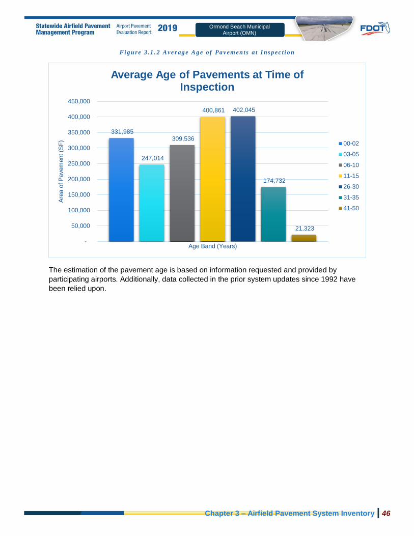
Chapter 3 – Airfield Pavement System Inventory | 46
Ormond Beach Municipal
Airport (OMN)
Fi g u re 3 .1 . 2 Ave r ag e Ag e of Pa v em en ts a t I ns p ec t i o n
The estimation of the pavement age is based on information requested and provided by
participating airports. Additionally, data collected in the prior system updates since 1992 have
been relied upon.
331,985
247,014
309,536
400,861 402,045
174,732
21,323
-
50,000
100,000
150,000
200,000
250,000
300,000
350,000
400,000
450,000
Are
a o
f P
avem
ent (S
F)
Age Band (Years)
Average Age of Pavements at Time of Inspection
00-02
03-05
06-10
11-15
26-30
31-35
41-50

Chapter 3 – Airfield Pavement System Inventory | 47
Ormond Beach Municipal
Airport (OMN)
3.1.3 Functional Use Classif icat ion
Pavements are subject to varying aircraft loading patterns based on utilization and overall
operations. For this SAPMP Update, the following categories of airfield functional use have
been identified and associated with the following possible pavement branch facilities: Apron,
Runway, Taxiway, and Taxilane. Figure 3.1.3 summarizes the identified pavements’ functional
use by area in square feet. The pavement areas reviewed exclude shoulder pavement facilities.
Fi g u re 3 .1 . 3 Ai r f i e l d Pav em e nt Fu n ct io n al Cl a ss i f i c at io n Us e b y Are a
578,723
663,450
645,323
520,000
540,000
560,000
580,000
600,000
620,000
640,000
660,000
680,000
APRON RUNWAY TAXIWAY
Are
a (
Square
Feet)
Functional Branch Use Classification
Airfield Pavement Functional Classification Use by Area

Chapter 3 – Airfield Pavement System Inventory | 48
Ormond Beach Municipal
Airport (OMN)
3.1.4 Pavement Surface Type
The airfield pavement facility surface types within the SAPMP include four common types of
pavement: Portland cement concrete (PCC), asphalt concrete (AC), asphalt concrete overlaid
on asphalt concrete (AAC), and asphalt concrete overlaid on Portland cement concrete (APC).
Based on the record documentation incorporated within the SAPMP database throughout the
years, the pavement surface types have been assigned to the various pavement sections in
accordance to its work history composition. The following Figures 3.1.4 (a) and (b) summarize
the applicable pavement types observed at this specific airport’s airfield.
Fi g u re 3 .1 . 4 ( a ) Pav em e nt S u rf a ce Ty p e by Ar e a (S F)
638,043
1,232,198
17,255
-
200,000
400,000
600,000
800,000
1,000,000
1,200,000
1,400,000
AAC - Asphalt ConcreteOverlaid on AC
AC - Asphalt Concrete PCC - Portland CementConcrete
Are
a (
Square
Feet)
Pavement Surface Type
Airfield Pavement Surface Type by Area (SF)

Chapter 3 – Airfield Pavement System Inventory | 49
Ormond Beach Municipal
Airport (OMN)
Fi g u re 3 .1 . 4 ( b ) Pav em e nt S u rf a ce Ty p e by Ar e a (%)
3.1.5 Pavement System Inventory Details
The following Table 3.1.5 displays the section-level details assembled as part of this update.
The section-level details are based on the record documentation provided by the airports to
FDOT and from SAPMP System Updates. The details assembled rely on the accuracy and the
adequacy of data provided; however, it should be noted that characteristics such as pavement
areas may be based on aerial interpretation of spatially projected imagery. The accuracy of data
is presented with the intention of a network planning-level document; should the airport elect to
perform rehabilitation work, it is recommended that further investigation be performed at the
project level for construction purposes.
In summary, the scope of the pavement inventory update resulted in the updating of select
existing pavement geometry and the development of an AutoCAD model with spatial projection
for use within GIS. Appendix A includes the Airfield Pavement Network Definition Exhibit and
the Airfield Pavement System Inventory Exhibit which visually summarize the results of the
Airfield Pavement System Inventory analysis and reporting.
34%
65%
1%
Pavement Surface Type by Area (%)
AAC - Asphalt Concrete Overlaid onAC
AC - Asphalt Concrete
PCC - Portland Cement Concrete

Chapter 3 – Airfield Pavement System Inventory | 50
Ormond Beach Municipal
Airport (OMN)
Ta b le 3 . 1 . 5 Pav em e nt S y s t em I nv e nt o ry De ta i l s
Network ID
Branch Name Branch ID Branch Use Section
ID Length
(FT) Width (FT)
Area (SF) Surface
Type
Est. Last Construction
Date
OMN CENTER APRON AP CENTER APRON 4204 285 22 5,932 AC 7/31/2008
OMN CENTER APRON AP CENTER APRON 4205 600 218 141,436 AAC 1/1/1992
OMN EAST APRON - HANGAR AREA AP E APRON 4305 342 150 52,638 AC 1/1/1984
OMN RUN-UP APRON AP RU APRON 5110 300 100 28,383 AC 1/1/2013
OMN RUN-UP APRON AP RU APRON 5115 300 100 28,289 AC 1/1/2013
OMN RUN-UP APRON AP RU APRON 5120 385 105 40,182 AC 1/1/2016
OMN RUN-UP APRON AP RU APRON 5125 385 105 40,187 AC 1/1/2016
OMN AP T HANG AP T HANG APRON 4410 2,000 25 54,829 AC 1/1/2005
OMN WEST APRON AP W APRON 4102 670 34 22,255 AC 1/1/1992
OMN WEST APRON AP W APRON 4105 835 180 164,592 AC 1/1/1992
OMN RUNWAY 17-35 RW 17-35 RUNWAY 6205 3,300 100 329,912 AAC 1/1/2008
OMN RUNWAY 17-35 RW 17-35 RUNWAY 6210 100 100 10,188 AAC 1/1/2008
OMN RUNWAY 17-35 RW 17-35 RUNWAY 6215 300 100 30,400 AC 1/1/2019
OMN RUNWAY 8-26 RW 8-26 RUNWAY 6105 4,000 75 292,950 AC 1/1/2019
OMN TAXIWAY A TW A TAXIWAY 100 4,250 35 149,004 AC 1/1/2013
OMN TAXIWAY A TW A TAXIWAY 102 51 48 2,434 AC 1/1/2019
OMN TAXIWAY A TW A TAXIWAY 105 130 35 4,550 AAC 1/1/2016
OMN TAXIWAY A TW A TAXIWAY 110 194 40 8,089 AC 1/1/2013
OMN TAXIWAY A TW A TAXIWAY 112 51 60 3,083 AC 1/1/2019
OMN TAXIWAY A TW A TAXIWAY 115 193 40 8,054 AC 1/1/2013
OMN TAXIWAY A TW A TAXIWAY 117 52 60 3,118 AC 1/1/2019
OMN TAXIWAY B TW B TAXIWAY 205 495 40 21,323 AAC 1/1/1977
OMN TAXIWAY B TW B TAXIWAY 210 143 120 9,023 AC 1/1/2013
OMN TAXIWAY C TW C TAXIWAY 305 1,160 50 35,470 AC 1/1/2013
OMN TAXIWAY D TW D TAXIWAY 405 2,160 45 74,127 AAC 1/1/1984

Chapter 3 – Airfield Pavement System Inventory | 51
Ormond Beach Municipal
Airport (OMN)
Network ID
Branch Name Branch ID Branch Use Section
ID Length
(FT) Width (FT)
Area (SF) Surface
Type
Est. Last Construction
Date
OMN TAXIWAY D TW D TAXIWAY 410 200 40 14,057 AC 1/1/2013
OMN TAXIWAY E TW E TAXIWAY 505 2,060 35 56,507 AAC 1/1/1990
OMN TAXIWAY E TW E TAXIWAY 510 800 35 29,167 AC 1/1/2013
OMN TAXIWAY F TW F TAXIWAY 605 1,040 40 41,694 AC 1/1/1984
OMN TAXIWAY F TW F TAXIWAY 650 130 40 6,273 AC 1/1/1984
OMN TAXIWAY G TW G TAXIWAY 700 4,190 35 144,093 AC 1/1/2016
OMN TAXIWAY G2 TW G2 TAXIWAY 705 230 35 9,003 AC 1/1/2016
OMN TAXIWAY G3 TW G3 TAXIWAY 710 230 35 8,999 AC 1/1/2016
OMN TAXIWAY TO T-HANGARS TW T-HANG TAXIWAY 2004 640 22 17,255 PCC 1/1/1992

Chapter 3 – Airfield Pavement System Inventory | 52
Ormond Beach Municipal
Airport (OMN)
PAGE INTENTIONALLY LEFT BLANK

Chapter 4
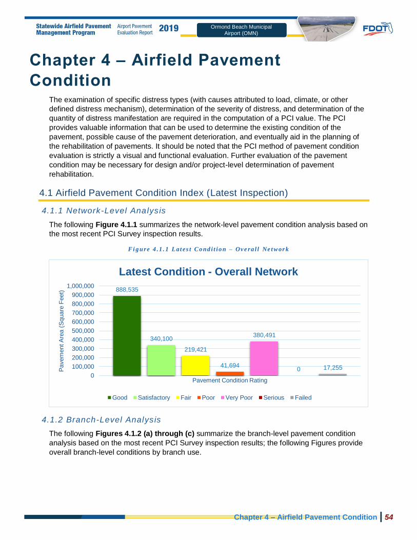
Chapter 4 – Airfield Pavement Condition | 54
AIKEN MUNICIPAL AIRPORT (AIK)
Ormond Beach Municipal
Airport (OMN)
Chapter 4 – Airfield Pavement
Condition The examination of specific distress types (with causes attributed to load, climate, or other
defined distress mechanism), determination of the severity of distress, and determination of the
quantity of distress manifestation are required in the computation of a PCI value. The PCI
provides valuable information that can be used to determine the existing condition of the
pavement, possible cause of the pavement deterioration, and eventually aid in the planning of
the rehabilitation of pavements. It should be noted that the PCI method of pavement condition
evaluation is strictly a visual and functional evaluation. Further evaluation of the pavement
condition may be necessary for design and/or project-level determination of pavement
rehabilitation.
4.1 Airfield Pavement Condition Index (Latest Inspection)
4.1.1 Network-Level Analysis
The following Figure 4.1.1 summarizes the network-level pavement condition analysis based on
the most recent PCI Survey inspection results.
Fi g u re 4 .1 . 1 Lat es t Co nd i t io n – Ov e ra l l Ne t wor k
4.1.2 Branch-Level Analysis
The following Figures 4.1.2 (a) through (c) summarize the branch-level pavement condition
analysis based on the most recent PCI Survey inspection results; the following Figures provide
overall branch-level conditions by branch use.
888,535
340,100
219,421
41,694
380,491
0 17,255
0
100,000
200,000
300,000
400,000
500,000
600,000
700,000
800,000
900,000
1,000,000
Pavem
ent A
rea (
Square
Feet)
Pavement Condition Rating
Latest Condition - Overall Network
Good Satisfactory Fair Poor Very Poor Serious Failed

Chapter 4 – Airfield Pavement Condition | 55
AIKEN MUNICIPAL AIRPORT (AIK)
Ormond Beach Municipal
Airport (OMN)
Fi g u re 4 .1 . 2 ( a ) Lat es t Co n di t io n – Ru n wa y Pa vem e nt s
Fi g u re 4 .1 . 2 ( b ) Lat es t Co n di t io n – Ta x i wa y Pa vem e nt s
323,350340,100
0 0 0 0 00
50,000
100,000
150,000
200,000
250,000
300,000
350,000
400,000
Pavem
ent A
rea (
Square
Feet)
Pavement Condition Rating
Latest Condition - Runway Pavements
Good Satisfactory Fair Poor Very Poor Serious Failed
428,144
0 0
41,694
158,230
017,255
0
50,000
100,000
150,000
200,000
250,000
300,000
350,000
400,000
450,000
Pavem
ent A
rea (
Square
Feet)
Pavement Condition Rating
Latest Condition - Taxiway Pavements
Good Satisfactory Fair Poor Very Poor Serious Failed

Chapter 4 – Airfield Pavement Condition | 56
AIKEN MUNICIPAL AIRPORT (AIK)
Ormond Beach Municipal
Airport (OMN)
Fi g u re 4 .1 . 2 ( c ) Lat es t Co nd i t io n – Ap r o n Pav em en t s
4.1.3 Sect ion-Level Analysis
The following Table 4.1.3 provides details for each pavement section of its area-weighted
average PCI and the percent of distress which is related to load, climate, or other factors. The
amount of distress attributed to the various causes provides insight into maintenance, repair,
and rehabilitation needs. Load-related distress indicates that pavements are reaching the end of
their structural design life, and for those pavements exhibiting a significant amount of these
distress types, rehabilitation should be planned to strengthen or reconstruct the pavement.
Appendix C Technical Exhibits provides a technical exhibit that graphically depicts the PCI
values and ratings determined from this SAPMP System Update.
Any pavement facilities subject to pavement construction within the past 2 years or anticipated
for construction within the next year may have been omitted from inspection. Pavement subject
to major rehabilitation will be set to a PCI of 100.
137,041
0
219,421
0
222,261
0 00
50,000
100,000
150,000
200,000
250,000
Pavem
ent A
rea (
Square
Feet)
Pavement Condition Rating
Latest Condition - Apron Pavements
Good Satisfactory Fair Poor Very Poor Serious Failed

Chapter 4 – Airfield Pavement Condition | 57
Ormond Beach Municipal Airport (OMN)
Ta b le 4 . 1 . 3 Lat es t Pa vem e nt Co n di t i o n I nd e x S umm ar y
Network ID Branch ID Branch Name Branch Use Section ID Area (SF) Surface PCI PCI Rating PCI % Climate PCI % Load PCI % Other Sample Units
Inspected Total Sample Units
in Section
OMN AP CENTER CENTER APRON APRON 4204 5,932 AC 30 Very Poor 100% 0% 0% 1 2
OMN AP CENTER CENTER APRON APRON 4205 141,436 AAC 33 Very Poor 81% 18% 1% 4 26
OMN AP E EAST APRON - HANGAR AREA APRON 4305 52,638 AC 28 Very Poor 56% 37% 7% 3 11
OMN AP RU RUN-UP APRON APRON 5110 28,383 AC 94 Good 100% 0% 0% 1 5
OMN AP RU RUN-UP APRON APRON 5115 28,289 AC 91 Good 100% 0% 0% 1 6
OMN AP RU RUN-UP APRON APRON 5120 40,182 AC 94 Good 100% 0% 0% 1 8
OMN AP RU RUN-UP APRON APRON 5125 40,187 AC 94 Good 100% 0% 0% 1 8
OMN AP T HANG AP T HANG APRON 4410 54,829 AC 68 Fair 59% 29% 12% 2 11
OMN AP W WEST APRON APRON 4102 22,255 AC 28 Very Poor 72% 0% 28% 1 7
OMN AP W WEST APRON APRON 4105 164,592 AC 61 Fair 96% 0% 4% 4 39
OMN RW 17-35 RUNWAY 17-35 RUNWAY 6205 329,912 AAC 73 Satisfactory 86% 0% 14% 14 66
OMN RW 17-35 RUNWAY 17-35 RUNWAY 6210 10,188 AAC 72 Satisfactory 77% 0% 23% 1 2
OMN RW 17-35 RUNWAY 17-35 RUNWAY 6215 30,400 AC 100 Good 0% 0% 0% 0 0
OMN RW 8-26 RUNWAY 8-26 RUNWAY 6105 292,950 AC 100 Good 0% 0% 0% 0 0
OMN TW A TAXIWAY A TAXIWAY 100 149,004 AC 93 Good 100% 0% 0% 5 41
OMN TW A TAXIWAY A TAXIWAY 102 2,434 AC 100 Good 0% 0% 0% 0 0
OMN TW A TAXIWAY A TAXIWAY 105 4,550 AAC 94 Good 100% 0% 0% 1 1
OMN TW A TAXIWAY A TAXIWAY 110 8,089 AC 90 Good 100% 0% 0% 1 2
OMN TW A TAXIWAY A TAXIWAY 112 3,083 AC 100 Good 0% 0% 0% 0 0
OMN TW A TAXIWAY A TAXIWAY 115 8,054 AC 94 Good 100% 0% 0% 1 2
OMN TW A TAXIWAY A TAXIWAY 117 3,118 AC 100 Good 0% 0% 0% 0 0
OMN TW B TAXIWAY B TAXIWAY 205 21,323 AAC 37 Very Poor 86% 0% 14% 2 5
OMN TW B TAXIWAY B TAXIWAY 210 9,023 AC 94 Good 100% 0% 0% 1 2
OMN TW C TAXIWAY C TAXIWAY 305 35,470 AC 94 Good 100% 0% 0% 2 9
OMN TW D TAXIWAY D TAXIWAY 405 74,127 AAC 38 Very Poor 79% 0% 21% 5 16
OMN TW D TAXIWAY D TAXIWAY 410 14,057 AC 94 Good 100% 0% 0% 1 3
OMN TW E TAXIWAY E TAXIWAY 505 56,507 AAC 38 Very Poor 97% 0% 3% 3 16
OMN TW E TAXIWAY E TAXIWAY 510 29,167 AC 94 Good 100% 0% 0% 1 8
OMN TW F TAXIWAY F TAXIWAY 605 41,694 AC 46 Poor 97% 0% 3% 2 10
OMN TW F TAXIWAY F TAXIWAY 650 6,273 AC 36 Very Poor 87% 0% 13% 1 1
OMN TW G TAXIWAY G TAXIWAY 700 144,093 AC 91 Good 59% 0% 41% 4 39
OMN TW G2 TAXIWAY G2 TAXIWAY 705 9,003 AC 94 Good 100% 0% 0% 1 2
OMN TW G3 TAXIWAY G3 TAXIWAY 710 8,999 AC 94 Good 100% 0% 0% 1 2
OMN TW T-HANG TAXIWAY TO T-HANGARS TAXIWAY 2004 17,255 PCC 9 Failed 10% 86% 4% 1 3

Chapter 4 – Airfield Pavement Condition | 58
Ormond Beach Municipal
Airport (OMN)
Figure 4.1.3 is an inset view of the 2019 Airfield Pavement Condition Index Exhibit that visually
represents the results of the latest PCI Survey inspection. A large format exhibit is located in
Appendix C Technical Exhibits.
Fi g u re 4 .1 . 3 20 1 9 A ir f i e l d Pa vem e nt Con d i t i o n I nd e x Ex h ib i t

Chapter 4 – Airfield Pavement Condition | 59
Ormond Beach Municipal
Airport (OMN)
4.2 Summary of Pavement Condition Evaluation Results
4.2.1 Network-Level Observat ions
The field PCI Survey performed at Ormond Beach Municipal Airport (OMN) was completed in
January 2019.The resulting overall area-weighted average PCI value was 73 representing a
condition rating of Satisfactory. Ormond Beach Municipal Airport is serviced by two runways;
Runway 8-26 is 75-ft wide and 4,005-ft long and Runway 17-35 is 100-ft wide and 3,704-ft long.
Runway 8-26, portions of the connecting taxiways, and a portion of runway 17-35 were not
inspected due to recent construction. The PCI for these areas has been set to 100, a condition
rating of Good.
Based on the FAA 5010 Report as of 09/12/2019 the Airport has reported 127,000 operations
for 12 months ending 02/08/2018.
4.2.2 Branch-Level Observat ions
The following branch-level observations are intended to be an overall summary of select
pavement facilities identified during the PCI Survey; further detail at the section and sample-
level may be referenced for all pavements assessed as part of this System Update. The branch-
level observations discussed are limited to select branches based on use and condition.
Runway 17-35
Runway 17-35 consists of 3 sections constructed of AC and AAC. The last construction years
range from 2008 to 2019. The area-weighted average PCI for Runway 17-35 is 75 representing
a Satisfactory condition rating. The pavement distresses observed were related to Climate and
Other distress classifications. Distresses observed on Runway 17-35 consist of Longitudinal &
Transverse Cracking, Raveling, Swelling, and Weathering.
Taxiway B
Taxiway B consists of 2 sections constructed of AC and AAC. The last construction years range
from 1977 to 2013. The area-weighted average PCI for Taxiway B is 51 representing a Poor
condition rating. The pavement distresses observed were related to Climate and Other distress
classifications. Distresses observed on Taxiway B consist of Block Cracking, Depression,
Raveling, Swelling, and Weathering.
Taxiway D
Taxiway D consists of 2 sections constructed of AC and AAC. The last construction years range
from 1984 to 2013. The area-weighted average PCI for Taxiway D is 46 representing a Poor
condition rating. The pavement distresses observed were related to Climate and Other distress
classifications. Distresses observed on Taxiway D consist of Block Cracking, Depression,
Longitudinal & Transverse Cracking, Patching, Raveling, Shoving, Swelling, and Weathering.

Chapter 4 – Airfield Pavement Condition | 60
Ormond Beach Municipal
Airport (OMN)
Taxiway E
Taxiway E consists of 2 sections constructed of AC and AAC. The last construction years range
from 1990 to 2013. The area-weighted average PCI for Taxiway E is 57 representing a Fair
condition rating. The pavement distresses observed were related to Climate and Other distress
classifications. Distresses observed on Taxiway E consist of Block Cracking, Patching,
Raveling, Swelling, and Weathering.
Taxiway F
Taxiway F consists of 2 sections constructed of AC. The last construction year for Taxiway F
was 1984. The area-weighted average PCI for Taxiway F is 44 representing a Poor condition
rating. The pavement distresses observed were related to Climate and Other distress
classifications. Distresses observed on Taxiway F consist of Block Cracking, Longitudinal &
Transverse Cracking, Patching, Raveling, and Swelling.
Center Apron
The Center Apron consists of 2 sections constructed of AC and AAC. The last construction
years range from 1992 to 2008. The area-weighted average PCI for the Center Apron is 32
representing a Very Poor condition rating. The pavement distresses observed were related to
Climate, Load, and Other distress classifications. Distresses observed on the Center Apron
consist of Alligator Cracking, Block Cracking, Depression, Longitudinal & Transverse Cracking,
Patching, and Raveling.
West Apron
The West Apron consists of 2 sections constructed of AC. The last construction year for West
Apron was 1992. The area-weighted average PCI for the West Apron is 57 representing a Fair
condition rating. The pavement distresses observed were related to Climate and Other distress
classifications. Distresses observed on the West Apron consist of Block Cracking, Longitudinal
& Transverse Cracking, Oil Spillage, Patching, Raveling, Swelling, and Weathering.
Fi g u re 4 . 2 . 2 Pav em e nt Co n di t i o n S umm ar y b y Faci l i t y Us e
Facility Use Area-Weighted Average PCI Condition Rating
Runway 86 Good
Taxiway 73 Satisfactory
Apron 57 Fair

Chapter 4 – Airfield Pavement Condition | 61
Ormond Beach Municipal
Airport (OMN)
4.3 Forecasted Pavement Conditions
4.3.1 Performance Models and Predict ion Curves
Pavement Performance Models are developed from the distress data and historic construction
records collected for the SAPMP. This data is consolidated in a database and organized by
inspection/construction date, pavement type, age, and pavement use. The pavement
Performance Models are used to develop broad Prediction Curves, alternatively known as
deterioration curves or family curves. These Prediction Curves are utilized to developed
forecasted PCI values based on historic trends and statistical models.
4.3.2 Branch-Level Pavement Condit ion Forecast
The following Figures 4.3.2 (a) through (c) depict the branch-level pavement condition forecast
by Branch Use (Runway, Taxiway, and/or Apron). The forecasted conditions are for a 10-year
duration starting in January 2020 through January 2029.
Fi g u re 4 . 3 . 2 ( a ) For e ca s t e d Ru n way Pa v em en t Perf o rm a nc e
84 83 81 79 78 76 75 73 72 71
0
10
20
30
40
50
60
70
80
90
100
2019 2021 2023 2025 2027 2029 2031
Fore
caste
d P
CI
(Bra
nch A
rea A
vera
ge)
Program Year
Forecasted Average Pavement Performance -Runway Pavements
Recommended Min. RW PCI 75 Forecasted RW PCI

Chapter 4 – Airfield Pavement Condition | 62
Ormond Beach Municipal
Airport (OMN)
Fi g u re 4 . 3 . 2 ( b ) For e ca s t e d Ta xi way Pa v em en t Per f orm a n ce
Fi g u re 4 . 3 . 2 ( c ) For e ca s t e d Apr o n Pa vem e nt Pe rfo rm a n ce
56 54 53 5250 49
4746 45 44
0
10
20
30
40
50
60
70
80
90
100
2019 2021 2023 2025 2027 2029 2031
Fore
caste
d P
CI
(Bra
nch A
rea A
vera
ge)
Program Year
Forecasted Average Pavement Performance -Apron Pavements
Recommended Min. AP PCI 60 Forecasted AP PCI
72 70 69 67 66 64 6361 60 58
0
10
20
30
40
50
60
70
80
90
100
2019 2021 2023 2025 2027 2029 2031
Fore
caste
d P
CI
(Bra
nch A
rea A
vera
ge)
Program Year
Forecasted Average Pavement Performance -Taxiway Pavements
Recommended Min. TW PCI 65 Forecasted TW PCI

Chapter 4 – Airfield Pavement Condition | 63
Ormond Beach Municipal
Airport (OMN)
4.3.3 Sect ion-Level Pavement Condit ion Forecast
The following Table 4.3.3 provides detail to the forecasted PCI values for each section
inspected. Please note the forecasted Branch- and Section-Level PCI’s are for planning
purposes and are subject to the sensitivities in changes in traffic and maintenance frequency.
Airport staff should perform annual visual condition assessments to maintain recent
understanding of pavement conditions.

Chapter 4 – Airfield Pavement Condition | 64
AIKEN MUNICIPAL AIRPORT (AIK) Ormond Beach Municipal
Airport (OMN)
Ta b le 4 . 3 . 3 Fo re c as te d PCI 2 02 0 -2 0 2 9
Network ID
Branch ID Section
ID Last PCI
Forecasted PCI
2020 2021 2022 2023 2024 2025 2026 2027 2028 2029
OMN AP CENTER 4204 30 29 29 29 28 28 28 27 27 27 26
OMN AP CENTER 4205 33 30 28 26 24 22 20 17 15 13 11
OMN AP E 4305 28 27 27 26 26 26 25 25 25 24 24
OMN AP RU 5110 94 91 89 87 85 82 80 78 76 74 73
OMN AP RU 5115 91 88 86 84 82 80 78 76 74 72 70
OMN AP RU 5120 94 91 89 87 85 82 80 78 76 74 73
OMN AP RU 5125 94 91 89 87 85 82 80 78 76 74 73
OMN AP T HANG 4410 68 66 65 64 63 62 61 60 59 58 57
OMN AP W 4102 28 27 27 26 26 26 25 25 25 24 24
OMN AP W 4105 61 60 59 58 57 56 56 55 54 54 53
OMN RW 17-35 6205 73 71 70 69 68 67 66 65 65 64 63
OMN RW 17-35 6210 72 70 69 68 67 66 66 65 64 63 62
OMN RW 17-35 6215 100 98 96 93 91 89 87 85 82 81 79
OMN RW 8-26 6105 100 98 96 93 91 89 87 85 82 81 79
OMN TW A 100 93 91 89 88 86 85 83 82 80 79 77
OMN TW A 102 100 98 96 94 93 91 89 88 86 85 83
OMN TW A 105 94 91 89 87 85 84 82 80 79 77 76
OMN TW A 110 90 88 86 85 83 82 80 79 77 76 75
OMN TW A 112 100 98 96 94 93 91 89 88 86 85 83
OMN TW A 115 94 92 90 89 87 86 84 83 81 80 78
OMN TW A 117 100 98 96 94 93 91 89 88 86 85 83
OMN TW B 205 37 35 33 31 29 27 25 23 21 19 17
OMN TW B 210 94 92 90 89 87 86 84 83 81 80 78
OMN TW C 305 94 92 90 89 87 86 84 83 81 80 78
OMN TW D 405 38 36 34 32 30 28 26 24 22 20 18

Chapter 4 – Airfield Pavement Condition | 65
AIKEN MUNICIPAL AIRPORT (AIK) Ormond Beach Municipal
Airport (OMN)
Network ID
Branch ID Section
ID Last PCI
Forecasted PCI
2020 2021 2022 2023 2024 2025 2026 2027 2028 2029
OMN TW D 410 94 92 90 89 87 86 84 83 81 80 78
OMN TW E 505 38 36 34 32 30 28 26 24 22 20 18
OMN TW E 510 94 92 90 89 87 86 84 83 81 80 78
OMN TW F 605 46 45 44 43 43 42 41 41 40 40 39
OMN TW F 650 36 35 35 35 34 34 34 34 34 33 33
OMN TW G 700 91 89 87 86 84 83 81 80 78 77 76
OMN TW G2 705 94 92 90 89 87 86 84 83 81 80 78
OMN TW G3 710 94 92 90 89 87 86 84 83 81 80 78
OMN TW T-HANG 2004 9 7 6 5 4 3 2 1 0 0 0

Chapter 4 – Airfield Pavement Condition | 66
AIKEN MUNICIPAL AIRPORT (AIK)
Ormond Beach Municipal
Airport (OMN)
4.3.4 Forecasted PCI Considerat ions
As FDOT continues to update the SAPMP with future PCI Survey inspections and assembly of
airfield pavement construction work history, the performance models will be further refined. With
the refinement of additional PCI and work history data points, the forecasting of pavement
conditions will continue to better reflect the performance trends of airfield pavements in the
Florida Airports System. Forecasted or predicted pavement conditions for the airport are
intended for planning purposes only. Design-level recommendations for pavement rehabilitation
and/or reconstruction will require the appropriate application of the procedures defined in FAA
AC 150/5320-6F Airport Pavement Design and Evaluation and AC 150/5370-11B Use of
Nondestructive Testing in the Evaluation of Airport Pavements to determine structural
and/or functional conditions at the time of project.

Chapter 5

Chapter 5 – Localized Maintenance and Repair Planning | 68
Ormond Beach Municipal
Airport (OMN)
Chapter 5 – Localized Maintenance and
Repair Planning General Maintenance and Rehabilitation (M&R) methods are characterized under three broad
categories: localized maintenance and repair, global treatments, and major rehabilitation.
➢ Localized Maintenance and Repair includes patching and crack sealing.
➢ Global Treatments include surface seals and rejuvenators for flexible pavements.
➢ Major Rehabilitation includes overlays, significant slab replacement, and
reconstruction.
This chapter discusses the FDOT SAPMP Localized Maintenance and Repair Planning
approach. Proactive localized maintenance and repair, specifically preservation, is highly
recommended to the airports. However, it is certainly recognized that once pavements have
deteriorated below a certain condition, the facility would benefit from a more substantial
rehabilitation in lieu of localized efforts. Chapter 6 Major Rehabilitation Planning discusses the
addressing of pavements through timely rehabilitation once it has deteriorated below a critical
PCI where localized repairs may not be as cost effective.
5.1 Localized Maintenance and Repair
Localized maintenance and repair is best applied as a conservation measure and is oftentimes
applied to slow the rate of deterioration of distressed pavements; however, may be applied as a
temporary corrective measure in isolated areas. Localized maintenance and repair can be
applied either as a safety (“stopgap”) measure or preventive measure. Example distress types
subject to localized preventive maintenance and repair may consist of low-severity longitudinal
and transverse cracking and low-severity weathering. In many cases however, localized
stopgap repair is applied as a safety measure to address high-severity distress manifestations
when major rehabilitation is not funded for a given section with a PCI value below critical PCI.
Some agencies may elect to define both types; preventative and stopgap, as localized
maintenance.
Localized Stopgap/Safety Maintenance and Repair
Localized Stopgap or Safety Maintenance and Repair is defined as the localized distress repair
needed to keep pavements operational in a safe condition. These activities are typically applied
to high-severity distresses or distresses affecting operational activities. Typical pavement
section PCIs will range from 0 to 65.
Localized Preventive Maintenance and Repair
Localized Preventive Maintenance and Repair is defined as distress maintenance activities
performed with the primary objective of slowing the rate of deterioration. These activities
typically include crack sealing and patching. Typical pavement section PCIs will be above 65.

Chapter 5 – Localized Maintenance and Repair Planning | 69
Ormond Beach Municipal
Airport (OMN)
5.2 Localized Maintenance and Repair Policy
The resulting Localized Maintenance and Repair recommendations are identified based on the
policy defined in Table 5.2 (a) and Table 5.2 (b), for flexible asphalt concrete and rigid Portland
cement concrete pavements, respectively. The activities identified were based on the research
of practical pavement treatments in consideration of the FAA AC 150/5380-6C “Guidelines
and Procedures for Maintenance of Airport Pavements” and the FDOT Airfield
Pavement Distress Repair Manual. Additionally, the Engineering Technical Letter (ETL)
14-3: Preventive Maintenance Plan (PMP) for Airfield Pavements was referenced for
conservative application of pavement treatments. The Localized Maintenance and Repair
Policy and associated planning-level unit costs were developed in consideration of a
network-level analysis – it is strictly intended to provide a glimpse of the condition of the
airport pavements with a limited PCI survey effort.
The developed Localized Maintenance and Repair Policy and associated planning-level unit
costs were based on a statewide consideration of pavement treatments and review of state
construction costs for both Airfield Pavements and from the FDOT Historical Cost
Information archives. Furthermore, a consideration of limited repair quantities was factored
in the determination of conservative planning-level unit costs. The identified Localized
maintenance activities for both preventive and stopgap activities are based on a statewide
network approach; project-specific evaluation and maintenance quantities should be
developed prior to any construction.
Ta b le 5 . 2 (a ) Loc a l i ze d Ma i nt e na n c e an d Re p ai r – F le x ib le As p h al t Co nc re te
Distress Severity Description Code Work Type Work Unit
41 Low ALLIGATOR CR FDOT-PA-AF FDOT - PATCHING - AC FULL DEPTH SqFt
41 Medium ALLIGATOR CR FDOT-PA-AF FDOT - PATCHING - AC FULL DEPTH SqFt
41 High ALLIGATOR CR FDOT-PA-AF FDOT - PATCHING - AC FULL DEPTH SqFt
42 N/A BLEEDING FDOT-MO-PV FDOT - MONITOR N/A
43 Low BLOCK CR FDOT-MO-PV FDOT - MONITOR N/A
43 Medium BLOCK CR FDOT-CS-AC FDOT - CRACK SEALING - AC Ft
43 High BLOCK CR FDOT-PA-AP FDOT - PATCHING - AC PARTIAL DEPTH SqFt
44 Low CORRUGATION FDOT-ML-AC FDOT - MILLING - AC SqFt
44 Medium CORRUGATION FDOT-ML-AC FDOT - MILLING - AC SqFt
44 High CORRUGATION FDOT-PA-AF FDOT - PATCHING - AC FULL DEPTH SqFt
45 Low DEPRESSION FDOT-PA-AF FDOT - PATCHING - AC FULL DEPTH SqFt
45 Medium DEPRESSION FDOT-PA-AF FDOT - PATCHING - AC FULL DEPTH SqFt
45 High DEPRESSION FDOT-PA-AF FDOT - PATCHING - AC FULL DEPTH SqFt
46 N/A JET BLAST FDOT-PA-AP FDOT - PATCHING - AC PARTIAL DEPTH SqFt
47 Low JT REF. CR FDOT-MO-PV FDOT - MONITOR N/A
47 Medium JT REF. CR FDOT-CS-AC FDOT - CRACK SEALING - AC Ft
47 High JT REF. CR FDOT-CS-AC FDOT - CRACK SEALING - AC Ft

Chapter 5 – Localized Maintenance and Repair Planning | 70
Ormond Beach Municipal
Airport (OMN)
Distress Severity Description Code Work Type Work Unit
48 Low L & T CR FDOT-MO-PV FDOT - MONITOR N/A
48 Medium L & T CR FDOT-CS-AC FDOT - CRACK SEALING - AC Ft
48 High L & T CR FDOT-CS-AC FDOT - CRACK SEALING - AC Ft
49 N/A OIL SPILLAGE FDOT-PA-AP FDOT - PATCHING - AC PARTIAL DEPTH SqFt
50 Low PATCHING FDOT-MO-PV FDOT - MONITOR N/A
50 Medium PATCHING FDOT-PA-AF FDOT - PATCHING - AC FULL DEPTH SqFt
50 High PATCHING FDOT-PA-AF FDOT - PATCHING - AC FULL DEPTH SqFt
51 N/A POLISHED AG FDOT-SS-LO FDOT - SURFACE SEAL SqFt
52 Low RAVELING FDOT-SS-LO FDOT - SURFACE SEAL SqFt
52 Medium RAVELING FDOT-PA-AP FDOT - PATCHING - AC PARTIAL DEPTH SqFt
52 High RAVELING FDOT-PA-AP FDOT - PATCHING - AC PARTIAL DEPTH SqFt
53 Low RUTTING FDOT-MO-PV FDOT - MONITOR N/A
53 Medium RUTTING FDOT-PA-AF FDOT - PATCHING - AC FULL DEPTH SqFt
53 High RUTTING FDOT-PA-AF FDOT - PATCHING - AC FULL DEPTH SqFt
54 Low SHOVING FDOT-MO-PV FDOT - MONITOR N/A
54 Medium SHOVING FDOT-ML-AC FDOT - MILLING - AC SqFt
54 High SHOVING FDOT-PA-AF FDOT - PATCHING - AC FULL DEPTH SqFt
55 N/A SLIPPAGE CR FDOT-PA-AP FDOT - PATCHING - AC PARTIAL DEPTH SqFt
56 Low SWELLING FDOT-MO-PV FDOT - MONITOR N/A
56 Medium SWELLING FDOT-PA-AF FDOT - PATCHING - AC FULL DEPTH SqFt
56 High SWELLING FDOT-PA-AF FDOT - PATCHING - AC FULL DEPTH SqFt
57 Low WEATHERING FDOT-MO-PV FDOT - MONITOR N/A
57 Medium WEATHERING FDOT-SS-LO FDOT - SURFACE SEAL SqFt
57 High WEATHERING FDOT-PA-AP FDOT - PATCHING - AC PARTIAL DEPTH SqFt
Ta b le 5 . 2 (b ) Loc a l i ze d Ma i nt e na n c e an d Re p ai r – R i gi d Por t l a nd Cem en t Co nc re te
Distress Severity Description Code Work Type Work Unit
61 Low BLOW-UP FDOT-PA-PP FDOT - PATCHING - PCC PARTIAL DEPTH SqFt
61 Medium BLOW-UP FDOT-PA-PF FDOT - PATCHING - PCC FULL DEPTH SqFt
61 High BLOW-UP FDOT-SL-PC FDOT - SLAB REPLACEMENT - PCC SqFt
62 Low CORNER BREAK FDOT-CS-PC FDOT - CRACK SEALING - PCC Ft
62 Medium CORNER BREAK FDOT-PA-PF FDOT - PATCHING - PCC FULL DEPTH SqFt
62 High CORNER BREAK FDOT-PA-PF FDOT - PATCHING - PCC FULL DEPTH SqFt
63 Low LINEAR CR FDOT-MO-PV FDOT - MONITOR N/A
63 Medium LINEAR CR FDOT-CS-PC FDOT - CRACK SEALING - PCC Ft
63 High LINEAR CR FDOT-PA-PP FDOT - PATCHING - PCC PARTIAL DEPTH SqFt

Chapter 5 – Localized Maintenance and Repair Planning | 71
Ormond Beach Municipal
Airport (OMN)
Distress Severity Description Code Work Type Work Unit
64 Low DURABIL. CR FDOT-MO-PV FDOT - MONITOR N/A
64 Medium DURABIL. CR FDOT-PA-PF FDOT - PATCHING - PCC FULL DEPTH SqFt
64 High DURABIL. CR FDOT-SL-PC FDOT - SLAB REPLACEMENT - PCC SqFt
65 Low JT SEAL DMG FDOT-JS-PC FDOT - JOINT SEAL - PCC Ft
65 Medium JT SEAL DMG FDOT-JS-PC FDOT - JOINT SEAL - PCC Ft
65 High JT SEAL DMG FDOT-JS-PC FDOT - JOINT SEAL - PCC Ft
66 Low SMALL PATCH FDOT-MO-PV FDOT - MONITOR N/A
66 Medium SMALL PATCH FDOT-PA-PP FDOT - PATCHING - PCC PARTIAL DEPTH SqFt
66 High SMALL PATCH FDOT-PA-PP FDOT - PATCHING - PCC PARTIAL DEPTH SqFt
67 Low LARGE PATCH FDOT-MO-PV FDOT - MONITOR N/A
67 Medium LARGE PATCH FDOT-PA-PF FDOT - PATCHING - PCC FULL DEPTH SqFt
67 High LARGE PATCH FDOT-PA-PF FDOT - PATCHING - PCC FULL DEPTH SqFt
68 N/A POPOUTS FDOT-PO-FL FDOT - POPOUT FILLER SqFt
69 N/A PUMPING FDOT-SB-PC FDOT – SLAB STABILIZATION - PCC SqFt
70 Low SCALING FDOT-MO-PV FDOT - MONITOR N/A
70 Medium SCALING FDOT-PA-PP FDOT - PATCHING - PCC PARTIAL DEPTH SqFt
70 High SCALING FDOT-SL-PC FDOT - SLAB REPLACEMENT - PCC SqFt
71 Low FAULTING FDOT-MO-PV FDOT - MONITOR N/A
71 Medium FAULTING FDOT-GR-PP FDOT - GRINDING (LOCALIZED) Ft
71 High FAULTING FDOT-GR-PP FDOT - GRINDING (LOCALIZED) Ft
72 Low SHAT. SLAB FDOT-CS-PC FDOT - CRACK SEALING - PCC Ft
72 Medium SHAT. SLAB FDOT-SL-PC FDOT - SLAB REPLACEMENT - PCC SqFt
72 High SHAT. SLAB FDOT-SL-PC FDOT - SLAB REPLACEMENT - PCC SqFt
73 N/A SHRINKAGE CR FDOT-MO-PV FDOT - MONITOR N/A
74 Low JOINT SPALL FDOT-CS-PC FDOT - CRACK SEALING - PCC Ft
74 Medium JOINT SPALL FDOT-PA-PP FDOT - PATCHING - PCC PARTIAL DEPTH SqFt
74 High JOINT SPALL FDOT-PA-PP FDOT - PATCHING - PCC PARTIAL DEPTH SqFt
75 Low CORNER SPALL FDOT-CS-PC FDOT - CRACK SEALING - PCC Ft
75 Medium CORNER SPALL FDOT-PA-PP FDOT - PATCHING - PCC PARTIAL DEPTH SqFt
75 High CORNER SPALL FDOT-PA-PP FDOT - PATCHING - PCC PARTIAL DEPTH SqFt
76 Low ASR FDOT-MO-PV FDOT - MONITOR N/A
76 Medium ASR FDOT-PA-PF FDOT - PATCHING - PCC FULL DEPTH SqFt
76 High ASR FDOT-SL-PC FDOT - SLAB REPLACEMENT - PCC SqFt

Chapter 5 – Localized Maintenance and Repair Planning | 72
Ormond Beach Municipal
Airport (OMN)
Ta b le 5 . 2 (c ) Loc al i ze d Re pa ir Pl a n ni n g- Lev el Uni t Co s t s – Fl e xi bl e As p ha l t Co n cr e t e
Code Name Cost Units
FDOT-SS-LO FDOT - SURFACE SEAL $0.55 SqFt
FDOT-ML-AC FDOT - MILLING - AC $2.00 SqFt
FDOT-GR-PP FDOT - GRINDING (LOCALIZED) $2.00 Ft
FDOT-CS-AC FDOT - CRACK SEALING - AC $3.00 Ft
FDOT-MO-PV FDOT - MONITOR $0.00 SqFt
FDOT-PA-AF FDOT - PATCHING - AC FULL DEPTH $9.00 SqFt
FDOT-PA-AP FDOT - PATCHING - AC PARTIAL DEPTH $4.00 SqFt
Ta b le 5 . 2 (d ) Loc a l i ze d M& R P la n ni n g -Le ve l Uni t Co s t s – R ig i d Por t l a nd Cem e nt Con c re te
Code Name Cost Units
FDOT-PA-PF FDOT - PATCHING - PCC FULL DEPTH $150.00 SqFt
FDOT-SL-PC FDOT - SLAB REPLACEMENT - PCC $30.00 SqFt
FDOT-SB-PC FDOT - SLAB STABILIZATION - PCC $30.00 SqFt
FDOT-PA-PP FDOT - PATCHING - PCC PARTIAL DEPTH $72.00 SqFt
FDOT-PO-FL FDOT - POPOUT FILLER $0.05 SqFt
FDOT-GR-PP FDOT - GRINDING (LOCALIZED) $2.00 Ft
FDOT-CS-PC FDOT - CRACK SEALING - PCC $4.25 Ft
FDOT-MO-PV FDOT - MONITOR $0.00 N/A
FDOT-JS-PC FDOT - JOINT SEAL - PCC $2.75 Ft
*PCC Patching (Full Depth and Partial Depth) consider high-early-strength and high-performing repair material.

Chapter 5 – Localized Maintenance and Repair Planning | 73
Ormond Beach Municipal
Airport (OMN)
5.3 Localized Maintenance and Repair Analysis and Recommendations
The SAPMP provides a planning-level estimation of Localized Maintenance and Repair based
on the results of the latest PCI Survey Inspection performed at the airport. Based on the limited
sample units inspected, a statistical extrapolation of distresses at the section level is used to
estimate the quantities of recommended repair activities based on the policies defined in 5.2
Localized M&R Policy. The PCI Survey Inspections did not consist of 100% inspection of all
sample units; therefore, the section-level distress quantities used to estimate the Localized
Maintenance and Repair needs are for conceptual planning purposes. The accuracy of the
extrapolated distresses, and therefore work quantities, is subject to the amount of sample units
inspected and the concentration of distress types observed in sample units. Appendix B
provides the estimated Localized Maintenance and Repair based on this SAPMP’s PCI Survey
Inspection efforts. Localized Preventive Maintenance and Repair is typically applied to
pavements that are in a condition at or above the Critical PCI of 65. Localized Stopgap
Maintenance and Repair is typically applied to pavements that are below the Critical PCI of 65.
It is recommended that airport staff evaluate the application of Localized Maintenance and
Repair in concert with the planning of Major Rehabilitation efforts identified in Chapter 6 Major
Rehabilitation Planning. Pavements with Stopgap recommendations that are subject to near-
term Major Rehabilitation efforts may remove the need to perform localized maintenance efforts.
The following Table 5.3 (a) summarizes the anticipated Localized Maintenance and Repair
efforts based on the PCI Survey Inspection efforts performed at this airport as part of this
SAPMP System Update. The following table depicts planning-level costs rounded to the nearest
ten dollars.
Ta b le 5 . 3 (a ) S umm a ry o f A ir p or t Loc al i z e d M& R P l a n ni n g Cos t a n d Qu a nt i t y a t Net wo r k Le v el
Work Description Work
Category
Rough Estimate of
Work Quantity Work Units Planning Material Cost
FDOT - PATCHING - AC FULL DEPTH PREVENTIVE 1,730 SqFt $ 15,560.00
FDOT - PATCHING - AC PARTIAL DEPTH PREVENTIVE 235 SqFt $ 930.00
FDOT - SURFACE SEAL PREVENTIVE 141,710 SqFt $ 77,950.00
FDOT - SLAB REPLACEMENT - PCC STOPGAP 10,560 SqFt $ 316,800.00
FDOT - CRACK SEALING - AC STOPGAP 72,080 Ft $ 216,240.00
FDOT - PATCHING - AC FULL DEPTH STOPGAP 17,290 SqFt $ 155,580.00
FDOT - SURFACE SEAL STOPGAP 404,880 SqFt $ 222,690.00
FDOT - PATCHING - AC PARTIAL DEPTH STOPGAP 26,395 SqFt $ 105,580.00
FDOT - JOINT SEAL - PCC STOPGAP 685 Ft $ 1,880.00
FDOT - CRACK SEALING - PCC STOPGAP 630 Ft $ 2,680.00

Chapter 5 – Localized Maintenance and Repair Planning | 74
Ormond Beach Municipal
Airport (OMN)
The following Table 5.3 (b) provides further breakdown of the anticipated planning-level cost at
the section level for the pavements exhibiting distresses that would benefit from Localized M&R.
The table shows the approximate improved “End Condition” of the section after the application
of Localized M&R. The following table depicts planning-level costs rounded to the nearest ten
dollars.
Ta b le 5 . 3 (b ) S umm a ry o f A ir p or t Loc al i z e d M& R P l a n ni n g Cos t a n d Qu a nt i t y a t S ec t i o n Lev el
Network ID
Branch ID Section
ID Area (SF)
Start Condition
End Condition
Cost
OMN AP CENTER 4204 5,932 30 59 $ 6,180.00
OMN AP CENTER 4205 141,436 33 65 $ 272,320.00
OMN AP E 4305 52,638 28 61 $ 103,950.00
OMN AP RU 5110 28,383 94 94 $ -
OMN AP RU 5115 28,289 91 91 $ -
OMN AP RU 5120 40,182 94 94 $ -
OMN AP RU 5125 40,187 94 94 $ -
OMN AP T HANG 4410 54,829 68 92 $ 25,370.00
OMN AP W 4102 22,255 28 55 $ 27,270.00
OMN AP W 4105 164,592 61 71 $ 50,330.00
OMN RW 17-35 6205 329,912 73 87 $ 58,740.00
OMN RW 17-35 6210 10,188 72 83 $ 1,090.00
OMN RW 17-35 6215 30,400 100 100 $ -
OMN RW 8-26 6105 292,950 100 100 $ -
OMN TW A 100 149,004 93 93 $ -
OMN TW A 102 2,434 100 100 $ -
OMN TW A 105 4,550 94 94 $ -
OMN TW A 110 8,089 90 94 $ 90.00
OMN TW A 112 3,083 100 100 $ -
OMN TW A 115 8,054 94 94 $ -
OMN TW A 117 3,118 100 100 $ -
OMN TW B 205 21,323 37 59 $ 31,160.00
OMN TW B 210 9,023 94 94 $ -
OMN TW C 305 35,470 94 94 $ -
OMN TW D 405 74,127 38 63 $ 87,010.00
OMN TW D 410 14,057 94 94 $ -
OMN TW E 505 56,507 38 61 $ 82,410.00
OMN TW E 510 29,167 94 94 $ -
OMN TW F 605 41,694 46 63 $ 34,100.00
OMN TW F 650 6,273 36 55 $ 5,600.00
OMN TW G 700 144,093 91 92 $ 9,180.00
OMN TW G2 705 9,003 94 94 $ -

Chapter 5 – Localized Maintenance and Repair Planning | 75
Ormond Beach Municipal
Airport (OMN)
Network ID
Branch ID Section
ID Area (SF)
Start Condition
End Condition
Cost
OMN TW G3 710 8,999 94 94 $ -
OMN TW T-HANG 2004 17,255 9 58 $ 321,360.00
The following Table 5.3 (c) provides a summary of the anticipated planning-level costs for
Localized Preventive Maintenance and Repair and Localized Stopgap Maintenance and Repair.
The following table depicts planning-level costs rounded to the nearest ten dollars.
Ta b le 5 . 3 (c ) S umm ar y o f Loc al i z e d Ma i nt e na n ce
Work Category Cost
Preventive $ 94,440.00
Stopgap $ 1,021,450.00
Planning-Level Localized M&R Needs = $ 1,115,890.00

Chapter 6

Chapter 6 – Major Rehabilitation Planning | 77
Ormond Beach Municipal
Airport (OMN)
Chapter 6 – Major Rehabilitation
Planning
6.1 Major Rehabilitation
Major rehabilitation is recommended to correct or improve structural deficiencies and/or
functional deterioration for pavement sections within a network. Often, when pavements are
subject to significant changes in the aircraft fleet mix (frequency and type), major rehabilitation
is required to provide a pavement section to meet the traffic demand. Major rehabilitation is
recommended when a pavement section falls below the Critical PCI value that is defined during
the system customization or if a pavement section has a significant observation of load-related
distress. Observation of any load-related distress potentially indicates that the section may be
structurally deficient or that the aircraft loads being applied to the pavement section are different
than what the section was designed for. Figures 6.1 (a) and 6.1 (b) depict the decision process
for major rehabilitation project identification with the assumption of available funds. Should
funding be unavailable for pavement sections in need of major rehabilitation, the airport may
elect to apply the appropriate localized stopgap repair.
Fi g u re s 6 . 1 ( a) M aj or Re h a bi l i t a t i o n Pl a n ni n g Dec i s i o n Dia g ram , PCI ≤ Cr i t i ca l PCI

Chapter 6 – Major Rehabilitation Planning | 78
Ormond Beach Municipal
Airport (OMN)
Fi g u re s 6 . 1 ( b ) M aj or Re h a bi l i t a t i o n Pl a n ni n g Dec i s i o n Dia g ram , PCI > Cr i t i c a l PCI

Chapter 6 – Major Rehabilitation Planning | 79
Ormond Beach Municipal
Airport (OMN)
6.1.1 Crit ical PCI
For the FDOT SAPMP the development of a major rehabilitation program is based on the
Critical PCI concept. The Critical PCI concept assumes that it is more cost-effective to maintain
pavements above, rather than below their critical PCI. It is assumed that once a pavement
section deteriorates to the Critical PCI value that it is more cost-effective to complete a major
rehabilitation project rather than continuing to apply preventive maintenance. This method
includes defining the Critical PCI and introducing major rehabilitation work types.
Identification of annual and long-range Major Rehabilitation work plans are typically based on
the Critical PCI concept. The Critical PCI is defined as the PCI value at which the rate of loss
(deterioration) increases with time, or the cost of applying localized maintenance and repair
increases or is not effective. A Critical PCI is usually within a range of 55 and 70; the following
procedure is standard approach in developing a specific Critical PCI:
1. Develop a pavement performance model and refine a prediction model for the
pavements considered.
2. Select a localized maintenance and repair policy to be used in developing a work
plan.
3. Apply the selected localized policy to the pavement sections for a range of PCI.
4. Compute the unit cost per area for each PCI range.
5. Plot the cost versus the PCI.
6. Determine the Critical PCI based on the point where the cost is insignificant.
The FDOT SAPMP defines the Critical PCI at 65 – this is based on the historic trends in
pavement performance and Statewide planning efforts.
6.1.2 FDOT Recommended Minimum Service-Level PCI
The FDOT has recommended Minimum Service-Level PCI for airports’ airfield pavements
based on the following characteristics; airport type within FDOT SAPMP, branch use, and
expected aircraft operations. For the purposes of Major Rehabilitation, the Critical PCI is
typically the threshold condition that triggers major construction, however it is recommended
that the airports maintain the Minimum Service-Level PCI with a combination of Localized
Maintenance and Repair and timely Major Rehabilitation. Table 6.1.2 summarizes the FDOT
Recommended Minimum Service-Level PCI.
Ta b le 6 . 1 . 2 FDOT Re c omm en d e d M i nim um S e rv ice - Lev el PCI
Branch Use FDOT Recommended PCI Additional Consideration
Runway 75 Aircraft Fleet Mix Changes
Primary Runway
Taxiway / Taxilane 65 Aircraft Fleet Mix Changes
Expected Operations
Aprons / Run-Ups / Ramps 65 Ground Service Equipment
Non-Aircraft Operations (e.g. fueling)

Chapter 6 – Major Rehabilitation Planning | 80
Ormond Beach Municipal
Airport (OMN)
6.2 Major Rehabilitation Policy
6.2.1 Major Rehabil itat ion Pavement Section Development
The review of the existing as-built record documentation within the participating airports’
archives was used as the basis of the conceptual pavement design sections. Refinement of the
pavement section layers was performed in consideration of the FAA AC 150/ 5320-6F “Airport
Pavement Design and Evaluation.” It should be noted that no subsurface geotechnical
investigation, ALTA/ACSM Survey, topographic survey, utilities survey, environmental, or site
specific air traffic study(s) have been utilized in the development of the design criteria. No
warranty or assurance is implied in this document for final design nor construction for any
airfield pavements discussed within this report. The following Tables 6.2.1 (a) and (b) provide
details on the conceptual pavement sections developed for this study.
Major rehabilitation is divided into two policy categories as part of this program: Full-Depth
Reconstruction (Reconstruction) and Intermediate-Level Major Rehabilitation (Restoration).
Based on the pavement type, the general categories are defined as AC Reconstruction and AC
Restoration for AC, AAC, and APC flexible pavement types and PCC Reconstruction and PCC
Restoration for PCC rigid pavement types. The pavement sections have been based on the
average RL Airport Type requirements; no pavement design has been performed in accordance
with AC 150/5320-6F for the determined conceptual sections.
Ta b le 6 . 2 . 1 (a ) Co n ce pt u al Pa v em en t S ec t i o n f o r M aj o r Re ha b i l i t a t i o n – Fl ex i bl e Asp h al t
Co n c re t e
Rehabilitation Type Reliever (RL) Airport
AC Restoration
Combination of asphalt pavement milling and overlay with 25% of the areas subject to full-depth reconstruction.
PCI = 41 to 65
75% Mill and Overlay P-101 AC Milling (3”) P-603 Bituminous Tack P-401 (HMA) (3”)
25% AC Reconstruction P-101 Pavement Removal P-152 Subgrade (12”) P-211 Base (8”) P-602 Bituminous Prime P-603 Bituminous Tack P-401 HMA (4”) Excludes any paved shoulder features.
AC Reconstruction
Full-depth asphalt pavement section reconstruction.
PCI = 40 or less
P-101 Pavement Removal P-152 Subgrade (12”) P-211 Base (8”) P-602 Bituminous Prime P-603 Bituminous Tack P-401 HMA (4”) Excludes any paved shoulder features.

Chapter 6 – Major Rehabilitation Planning | 81
Ormond Beach Municipal
Airport (OMN)
Ta b le 6 . 2 . 1 (b ) Co n ce pt u al Pa v em en t S ec t i o n f o r M aj o r Re ha b i l i t a t i o n – Ri gi d Por t l a n d Cem en t
Co n c re t e
Rehabilitation Type Reliever (RL) Airport
PCC Restoration
Restoration of PCC pavement with a combination of crack sealing, joint seal replacement, and replacement of 25% of slab panels. PCI = 41 to 65
P-101 Pavement Removal P-605 Joint Seal Repair P-152 Subgrade (12”) P-211 Base (if needed, typical) (6”) P-501 Rigid PCC (15”) *Select Slabs (25%) **Crack Seal and Limited Patching
PCC Reconstruction
Full-depth rigid pavement section reconstruction.
PCI = 40 or less
P-101 Pavement Removal P-605 Joint Seal Repair P-152 Subgrade (12”) P-211 Base (6”) P-501 Rigid PCC (14”)
The identification of rehabilitation needs and conceptual pavement sections have been
determined at the planning level. Design-level investigation is recommended prior to
developing construction-level design documents and budgets.
In compliance with FAA Grant Assurances 11 and 19, the FDOT SAPMP provides airports with
airfield pavement evaluation reports in accordance with FAA AC 150/5380-7B Airport
Pavement Management Program (PMP) and AC 150/5380-6C Guidelines and Procedures
for Maintenance of Airport Pavements. The application of the results of a PCI survey are for
planning purposes and are limited to the visual observation of deteriorated pavements in limited
sampling; design-level investigation is recommended in accordance with the FAA procedures
defined in AC 5320-6F Airport Pavement Design and Evaluation and AC 150/5370-11B Use
of Nondestructive Testing in the Evaluation of Airport Pavements. The aforementioned
ACs provide the design-level material properties of in-situ pavement and subgrade layers for the
determination of appropriate rehabilitation actions. The FDOT SAPMP is organized to provide
airports with planning-level data and does not intend to preclude the responsible engineer in
performing the appropriate level of investigation and analysis in determining the appropriate
design details of a pavement rehabilitation. It would not be advisable to solely base design-level
rehabilitation without the appropriate level of investigation and determination of pavement
deterioration beyond that of a visual functional condition assessment.
The recommendations identified in the Major Rehabilitation Needs consider the FAA AC
150/5370-10H Standard Specifications for Construction of Airports when determining the
appropriate materials and methods implemented for construction projects, such as pavement
rehabilitation, on airports. It should be noted that the AC 150/5370-10H Standard
Specifications for Construction of Airports was updated in December of 2018. Design-level
determination of project specific specifications based on the AC should be developed by the
Airport when performing applicable construction projects.

Chapter 6 – Major Rehabilitation Planning | 82
Ormond Beach Municipal
Airport (OMN)
6.2.2 Major Rehabil itat ion Planning-Level Unit Costs
Planning-level opinion of probable construction unit costs developed for this System Update
was based on archived bid tabulations and records from airfield pavement projects provided by
participating airports. A review of cost trends and cost factors have been incorporated to assist
airports in planning for project budgets. Neither FDOT nor the Consultant Team has control over
the cost of labor, materials, equipment, or over the Contractor's methods of determining prices
or over competitive bidding or market conditions. Opinions of probable construction costs
provided herein are based on the information known to FDOT at this time and represent only the
Consultant Team’s judgment as a design professional familiar with the construction industry.
This report cannot and does not guarantee that proposals, bids, or actual construction costs will
not vary from its opinions of probable construction costs.
Ta b le 6 . 2 . 2 Rel i e v er ( RL) M aj o r Re ha bi l i ta t i o n P la n n i ng - Le v el Un i t Co s t by Pa v em en t Typ e
Rehabilitation Type PCI Range Flexible Asphalt
Concrete Cost Per SF Rigid Portland Cement Concrete Cost per SF
Restoration 41 to 65 $ 9.50 $ 13.50
Reconstruction 0 to 40 $ 12.50 $ 20.00
Planning-level opinion of probable construction unit costs consider factors for non-pavement improvements, QA/QC testing, and
administrative costs.
6.3 Major Rehabilitation Needs
The objective of the major pavement rehabilitation needs analysis is to provide planning-level
projects within an airport’s airfield pavement network. Major rehabilitation activities are
recommended when a pavement section has deteriorated below the Critical PCI value, a point
at which localized maintenance and repair activities may not be the most cost-effective solution.
In addition, major rehabilitation is also recommended when the Section PCI is at or above the
Critical PCI but the section has significant load-related PCI distresses. Identification of
rehabilitation needs is done at the Airfield Pavement Network Definition’s section level. This
however does not limit the airport from further refining limits of project planning areas.
Major rehabilitation is identified within the FDOT SAPMP as major construction activity that
would result in an improvement or resetting of the pavement section’s PCI to a value of 100.
Major rehabilitation recommendations (AC Restoration, AC Reconstruction, PCC Restoration,
and PCC Reconstruction) should be considered as planning-level only. Additional design-level
investigation in accordance to the FAA Advisory Circulars will be required. Recommendations
identified within this planning document do not imply final design.
6.3.1 10-Year Unconstra ined Budget Major Rehabil itat ion Needs
An unconstrained budget (unlimited budget) is performed for a 10-year duration to identify
pavement rehabilitation needs based on current or forecasted PCI values deteriorating below
the Critical PCI. FDOT recognizes airports are constrained by budgets and does not intend to
convey an unrealistic approach of addressing pavement rehabilitation. The intent of the 10-Year
Major Rehabilitation Needs analysis is to identify pavements that will warrant rehabilitation. It is
highly recommended that airport staff utilize this information in support of the development of a
practical Capital Improvement Program based on priorities, further design/project-level

Chapter 6 – Major Rehabilitation Planning | 83
Ormond Beach Municipal
Airport (OMN)
investigation, and budgetary constraints. The following Table 6.3.1 summarizes all identified
section-level major rehabilitation needs forecasted for the next 10-year period. It should be
noted that the following table depicts planning-level costs and have been rounded for planning
purposes.
Ta b le 6 . 3 . 1 1 0-Y ea r Ma j or Re h a bi l i t a t i on Nee d s
Program Year
Network ID
Branch ID Section
ID Surface
Area (SF)
PCI Before
Rehabilitation Type
Planning Cost
2020 OMN AP CENTER 4204 AC 5,932 29 AC Reconstruction $ 75,000.00
2020 OMN AP CENTER 4205 AAC 141,436 30 AC Reconstruction $ 1,768,000.00
2020 OMN AP E 4305 AC 52,638 27 AC Reconstruction $ 658,000.00
2020 OMN AP W 4102 AC 22,255 27 AC Reconstruction $ 279,000.00
2020 OMN AP W 4105 AC 164,592 60 AC Restoration $ 1,564,000.00
2020 OMN TW B 205 AAC 21,323 35 AC Reconstruction $ 267,000.00
2020 OMN TW D 405 AAC 74,127 36 AC Reconstruction $ 927,000.00
2020 OMN TW E 505 AAC 56,507 36 AC Reconstruction $ 707,000.00
2020 OMN TW F 605 AC 41,694 45 AC Restoration $ 455,000.00
2020 OMN TW F 650 AC 6,273 35 AC Reconstruction $ 79,000.00
2020 OMN TW T-HANG 2004 PCC 17,255 7 PCC Reconstruction $ 346,000.00
2022 OMN AP T HANG 4410 AC 54,829 64 AC Restoration $ 521,000.00
2027 OMN RW 17-35 6210 AAC 10,188 64 AC Restoration $ 97,000.00
2028 OMN RW 17-35 6205 AAC 329,912 64 AC Restoration $ 3,135,000.00
*All values have been rounded to the nearest thousand-dollar.
The following Figure 6.3.1 (a) summarizes the section-level major rehabilitation needs for a 10-
year period between 2020 and 2029. Figure 6.3.1 (b) provides an inset view of Airfield
Pavement Major Rehabilitation Exhibit, a large format exhibit is located in Appendix C
Technical Exhibits. The exhibit graphically depicts the Major Rehabilitation Needs with
rounded costs.

Chapter 6 – Major Rehabilitation Planning | 84
Ormond Beach Municipal
Airport (OMN)
Fi g u re 6 .3 . 1 ( a ) 1 0-Y ea r Ma j or Re h ab i l i t a t io n Nee d s b y Pro g ram Y ea r
Fi g u re 6 .3 . 1 ( b ) 1 0-Y ea r Ma j or Re h ab i l i t a t io n Nee d s b y Pro g ram Y ea r Ex hi bi t
$7,125,000
$-
$521,000
$- $- $- $- $97,000
$3,135,000
$- $-
$1,000,000
$2,000,000
$3,000,000
$4,000,000
$5,000,000
$6,000,000
$7,000,000
$8,000,000
2020 2021 2022 2023 2024 2025 2026 2027 2028 2029
Major Rehabilitation Needs by Program Year

Chapter 7

Chapter 7 – Conclusion | 86
Ormond Beach Municipal
Airport (OMN)
Chapter 7 – Conclusion
7.1 Recommendations
7.1.1 Cont inued PCI Survey Inspect ions
It is recommended that the airport continue to perform regularly scheduled PCI Survey
inspections in accordance with the ASTM D5340-12 (or latest edition) to monitor the condition of
the airfield pavement facilities.
A high priority should be considered for continuous maintenance record keeping and re-
inspection of all the airport’s maintained pavement facilities to ensure continued safe aircraft
operations. A series of scheduled periodic inspections must be carried out for an effective
maintenance program. Re-inspection of pavements should be scheduled in a timely manner to
ensure that all areas, particularly those that may not come under day-to-day observation, are
thoroughly evaluated and reported.
7.1.2 Local ized Maintenance and Repair
While deterioration of the pavements due to usage and exposure to the environment cannot be
completely prevented, applying timely and effective maintenance efforts can slow the
anticipated rate of deterioration. Lack of adequate and timely maintenance is the significant
factor in pavement deterioration.
It is recommended that airport sponsors coordinate with their respective Airport Maintenance
staff and Airport Engineer when developing project-level maintenance and repair efforts.
7.1.3 Major Rehabil itat ion
Chapter 6 – Major Rehabilitation Planning identified major pavement rehabilitation project needs
from 2020-2029. The identification of the rehabilitation needs was performed at the section level
for manageable project areas with the assumption of an unconstrained budget scenario. Given
the uncertainty in the airport-specific budget information and prioritization goals, the
unconstrained budget scenario was performed to evaluate the worst-case scenario and identify
all the inspected pavements’ needs in a 10-year period. Certainly, it is understood that most
airports are faced with constrained budgets; further evaluation of projects based on
prioritization, operational criticality, funding availability, and practicality is recommended.
7.1.4 Pavement Management System
The following recommendations are made to fully implement an effective pavement
management program for the airport:
Develop a detailed preventive maintenance program for the airport.
Further refine and implement the identified 10-year major rehabilitation needs.
Maintain detailed records on pavement maintenance, construction, and inspection.
Maintain records on major pavement construction projects (year, scope, cost, and
construction documents).

Chapter 7 – Conclusion | 87
Ormond Beach Municipal
Airport (OMN)
7.2 Supporting Documents
001 – Airf ield Pavement Network Def in it ion Exhibit
The Airfield Pavement Network Definition Exhibit is located in Appendix C Technical Exhibits.
The exhibit depicts the airfield layout in a manner that defines the airfield pavement
infrastructure as branches, sections, and sample units in accordance with the ASTM D5340-12.
The exhibit is intended for planning purposes only – further detail on facilities can be found on
the Airport’s adopted Airport Layout Plan. Detailed characteristics are tabulated in Appendix A
Pavement Analysis Tables.
002 – Airf ield Pavement System Inventory Exhibit
The Airfield Pavement System Inventory Exhibit in is located in Appendix C Technical
Exhibits. The exhibit depicts any recent and/or anticipated construction activity within the
airfield pavement facilities reported by airport staff. The exhibit is intended to schematically
identify the pavement limits of works and general work description. The information reported on
the Airport Response Form provided by each participating airport was used as the basis of the
changes; furthermore, changes are confirmed at the airport with airport staff during the in-brief
and debrief meeting.
003 – Airf ield Pavement Condit ion Index Exhibit
The Airfield Pavement Condition Index Exhibit is located in Appendix C Technical Exhibits.
The exhibit is a visual summary of the latest conditions calculated from the results of the PCI
Survey performed at the airport. The analysis of the distresses surveyed in accordance with the
ASTM D5340-12 (referenced in Appendix E Inspection Distress Details) were analyzed using
PAVERTM software to determine PCI values. The PCI values are identified in the exhibit and
graphically represented using the standard ASTM D5340-12 colors for condition rating
categories.
004 – Airf ield Pavement Major Rehabil i tation Exhibit
The Airfield Pavement Major Rehabilitation Exhibit is located in Appendix C Technical
Exhibits. The exhibit has been prepared based on the section condition analysis, pavement
condition forecasts, and major rehabilitation needs analysis. The exhibit graphically depicts the
inventory with the associated rehabilitation type activity, program year, and the planning-level
costs. The area limits, rehabilitation type, and planning-level costs should not be considered a
design-level recommendation. A tabulation of the 10-Year Major Rehabilitation is located in
Appendix B Airfield Pavement Localized Maintenance and Repair and Major
Rehabilitation.
Inspect ion Photograph Documentat ion
Representative field conditions from the PCI Survey are documented with digital photographs
located in Appendix D Inspection Photograph Documentation. Select photographs are
provided with limited caption on the distresses observed – the Appendix does not contain
photographs for every sample unit.

Chapter 7 – Conclusion | 88
Ormond Beach Municipal
Airport (OMN)
7.3 Conclusion
The FDOT SAPMP Update Phase 2 2018-2019 was completed for the airport on behalf of the
FDOT ASO in accordance with the Advisory Circulars 150/5380-7B “Airport Pavement
Management Program (PMP)” and 150/5380-6C “Guidelines and Procedures for
Maintenance of Airport Pavements.” FDOT’s implementation of the SAPMP has assisted
public airports with this requirement in performing PCI survey inspections and analysis in
accordance with the ASTM D5340-12 “Standard Test Method for Airport Pavement
Condition Index Surveys.”

Appendix AAirfield Pavement Analysis Tables

Appendix A | A-1
Ormond Beach Municipal
Airport (OMN)
Ta b le A- 1 Pa vem e nt Sy s t em I n ve nt o ry Det ai l s
Network ID
Branch Name Branch ID Branch
Use Section
ID Length
(FT) Width (FT)
Area (SF)
Surface Type
Est. Last Construction
Date
OMN CENTER APRON AP CENTER APRON 4204 285 22 5,932 AC 7/31/2008
OMN CENTER APRON AP CENTER APRON 4205 600 218 141,436 AAC 1/1/1992
OMN EAST APRON - HANGAR AREA AP E APRON 4305 342 150 52,638 AC 1/1/1984
OMN RUN-UP APRON AP RU APRON 5110 300 100 28,383 AC 1/1/2013
OMN RUN-UP APRON AP RU APRON 5115 300 100 28,289 AC 1/1/2013
OMN RUN-UP APRON AP RU APRON 5120 385 105 40,182 AC 1/1/2016
OMN RUN-UP APRON AP RU APRON 5125 385 105 40,187 AC 1/1/2016
OMN AP T HANG AP T HANG APRON 4410 2,000 25 54,829 AC 1/1/2005
OMN WEST APRON AP W APRON 4102 670 34 22,255 AC 1/1/1992
OMN WEST APRON AP W APRON 4105 835 180 164,592 AC 1/1/1992
OMN RUNWAY 17-35 RW 17-35 RUNWAY 6205 3,300 100 329,912 AAC 1/1/2008
OMN RUNWAY 17-35 RW 17-35 RUNWAY 6210 100 100 10,188 AAC 1/1/2008
OMN RUNWAY 17-35 RW 17-35 RUNWAY 6215 300 100 30,400 AC 1/1/2019
OMN RUNWAY 8-26 RW 8-26 RUNWAY 6105 4,000 75 292,950 AC 1/1/2019
OMN TAXIWAY A TW A TAXIWAY 100 4,250 35 149,004 AC 1/1/2013
OMN TAXIWAY A TW A TAXIWAY 102 51 48 2,434 AC 1/1/2019
OMN TAXIWAY A TW A TAXIWAY 105 130 35 4,550 AAC 1/1/2016
OMN TAXIWAY A TW A TAXIWAY 110 194 40 8,089 AC 1/1/2013
OMN TAXIWAY A TW A TAXIWAY 112 51 60 3,083 AC 1/1/2019
OMN TAXIWAY A TW A TAXIWAY 115 193 40 8,054 AC 1/1/2013
OMN TAXIWAY A TW A TAXIWAY 117 52 60 3,118 AC 1/1/2019
OMN TAXIWAY B TW B TAXIWAY 205 495 40 21,323 AAC 1/1/1977
OMN TAXIWAY B TW B TAXIWAY 210 143 120 9,023 AC 1/1/2013
OMN TAXIWAY C TW C TAXIWAY 305 1,160 50 35,470 AC 1/1/2013
OMN TAXIWAY D TW D TAXIWAY 405 2,160 45 74,127 AAC 1/1/1984
OMN TAXIWAY D TW D TAXIWAY 410 200 40 14,057 AC 1/1/2013
OMN TAXIWAY E TW E TAXIWAY 505 2,060 35 56,507 AAC 1/1/1990
OMN TAXIWAY E TW E TAXIWAY 510 800 35 29,167 AC 1/1/2013
OMN TAXIWAY F TW F TAXIWAY 605 1,040 40 41,694 AC 1/1/1984
OMN TAXIWAY F TW F TAXIWAY 650 130 40 6,273 AC 1/1/1984
OMN TAXIWAY G TW G TAXIWAY 700 4,190 35 144,093 AC 1/1/2016
OMN TAXIWAY G2 TW G2 TAXIWAY 705 230 35 9,003 AC 1/1/2016
OMN TAXIWAY G3 TW G3 TAXIWAY 710 230 35 8,999 AC 1/1/2016
OMN TAXIWAY TO T-HANGARS TW T-HANG TAXIWAY 2004 640 22 17,255 PCC 1/1/1992

Appendix A | A-2
Ormond Beach Municipal
Airport (OMN)
Ta b le A- 2 Pa vem e nt Con d i t i o n I n de x S umm a ry ( La s t I ns p ec t i o n) – S e c t io n Le ve l
Network ID
Branch Name Branch Use Section
ID Area (SF) PCI
Condition Rating
OMN RUNWAY 8-26 RUNWAY 6105 292,950 100 Good
OMN RUNWAY 17-35 RUNWAY 6205 329,912 73 Satisfactory
OMN RUNWAY 17-35 RUNWAY 6210 10,188 72 Satisfactory
OMN RUNWAY 17-35 RUNWAY 6215 30,400 100 Good
OMN TAXIWAY A TAXIWAY 100 149,004 93 Good
OMN TAXIWAY A TAXIWAY 102 2,434 100 Good
OMN TAXIWAY A TAXIWAY 105 4,550 94 Good
OMN TAXIWAY A TAXIWAY 110 8,089 90 Good
OMN TAXIWAY A TAXIWAY 112 3,083 100 Good
OMN TAXIWAY A TAXIWAY 115 8,054 94 Good
OMN TAXIWAY A TAXIWAY 117 3,118 100 Good
OMN TAXIWAY B TAXIWAY 205 21,323 37 Very Poor
OMN TAXIWAY B TAXIWAY 210 9,023 94 Good
OMN TAXIWAY C TAXIWAY 305 35,470 94 Good
OMN TAXIWAY D TAXIWAY 405 74,127 38 Very Poor
OMN TAXIWAY D TAXIWAY 410 14,057 94 Good
OMN TAXIWAY E TAXIWAY 505 56,507 38 Very Poor
OMN TAXIWAY E TAXIWAY 510 29,167 94 Good
OMN TAXIWAY F TAXIWAY 605 41,694 46 Poor
OMN TAXIWAY F TAXIWAY 650 6,273 36 Very Poor
OMN TAXIWAY G TAXIWAY 700 144,093 91 Good
OMN TAXIWAY G2 TAXIWAY 705 9,003 94 Good
OMN TAXIWAY G3 TAXIWAY 710 8,999 94 Good
OMN TAXIWAY TO T-HANGARS TAXIWAY 2004 17,255 9 Failed
OMN WEST APRON APRON 4102 22,255 28 Very Poor
OMN WEST APRON APRON 4105 164,592 61 Fair
OMN CENTER APRON APRON 4204 5,932 30 Very Poor
OMN CENTER APRON APRON 4205 141,436 33 Very Poor
OMN EAST APRON - HANGAR AREA APRON 4305 52,638 28 Very Poor
OMN AP T HANG APRON 4410 54,829 68 Fair
OMN RUN-UP APRON APRON 5110 28,383 94 Good
OMN RUN-UP APRON APRON 5115 28,289 91 Good
OMN RUN-UP APRON APRON 5120 40,182 94 Good
OMN RUN-UP APRON APRON 5125 40,187 94 Good

Appendix A | A-3
Ormond Beach Municipal
Airport (OMN)
Ta b le A- 3 Fo re c as te d PCI 2 0 20 - 20 2 9
Network ID
Branch ID Section
ID Last PCI
Forecasted PCI
2020 2021 2022 2023 2024 2025 2026 2027 2028 2029
OMN AP CENTER 4204 30 29 29 29 28 28 28 27 27 27 26
OMN AP CENTER 4205 33 30 28 26 24 22 20 17 15 13 11
OMN AP E 4305 28 27 27 26 26 26 25 25 25 24 24
OMN AP RU 5110 94 91 89 87 85 82 80 78 76 74 73
OMN AP RU 5115 91 88 86 84 82 80 78 76 74 72 70
OMN AP RU 5120 94 91 89 87 85 82 80 78 76 74 73
OMN AP RU 5125 94 91 89 87 85 82 80 78 76 74 73
OMN AP T HANG 4410 68 66 65 64 63 62 61 60 59 58 57
OMN AP W 4102 28 27 27 26 26 26 25 25 25 24 24
OMN AP W 4105 61 60 59 58 57 56 56 55 54 54 53
OMN RW 17-35 6205 73 71 70 69 68 67 66 65 65 64 63
OMN RW 17-35 6210 72 70 69 68 67 66 66 65 64 63 62
OMN RW 17-35 6215 100 98 96 93 91 89 87 85 82 81 79
OMN RW 8-26 6105 100 98 96 93 91 89 87 85 82 81 79
OMN TW A 100 93 91 89 88 86 85 83 82 80 79 77
OMN TW A 102 100 98 96 94 93 91 89 88 86 85 83
OMN TW A 105 94 91 89 87 85 84 82 80 79 77 76
OMN TW A 110 90 88 86 85 83 82 80 79 77 76 75
OMN TW A 112 100 98 96 94 93 91 89 88 86 85 83
OMN TW A 115 94 92 90 89 87 86 84 83 81 80 78
OMN TW A 117 100 98 96 94 93 91 89 88 86 85 83
OMN TW B 205 37 35 33 31 29 27 25 23 21 19 17
OMN TW B 210 94 92 90 89 87 86 84 83 81 80 78
OMN TW C 305 94 92 90 89 87 86 84 83 81 80 78
OMN TW D 405 38 36 34 32 30 28 26 24 22 20 18
OMN TW D 410 94 92 90 89 87 86 84 83 81 80 78
OMN TW E 505 38 36 34 32 30 28 26 24 22 20 18
OMN TW E 510 94 92 90 89 87 86 84 83 81 80 78
OMN TW F 605 46 45 44 43 43 42 41 41 40 40 39
OMN TW F 650 36 35 35 35 34 34 34 34 34 33 33
OMN TW G 700 91 89 87 86 84 83 81 80 78 77 76
OMN TW G2 705 94 92 90 89 87 86 84 83 81 80 78
OMN TW G3 710 94 92 90 89 87 86 84 83 81 80 78
OMN TW T-HANG 2004 9 7 6 5 4 3 2 1 0 0 0

Pavement Database:
Work History Report
FDOT
Page 1 of 710/4/2019
Work DateWorkCode
CostThickness
(in)MajorM&R
Network: ORMOND BEACH Branch: Section:AP CENTER CENTER APRON 4204 Surface:AC
L.C.D. 7/31/2008 Use: APRON Rank: T Length: 285.00 Width: 22.00 True Area: 5932.000001
CommentsWork Description
(SqFt (Ft) (Ft)
7/31/2008 XNU-IN New Construction - Initial 0.00 0.00
Work DateWorkCode
CostThickness
(in)MajorM&R
Network: ORMOND BEACH Branch: Section:AP CENTER CENTER APRON 4205 Surface:AAC
L.C.D. 1/1/1992 Use: APRON Rank: T Length: 600.00 Width: 218.00 True Area: 141436.0000
CommentsWork Description
(SqFt (Ft) (Ft)
1992: AC OVERLAY1/1/1992 XIMPORTED
OVERLAY 0.00 0.00
1979: 1" TYPE S1 AC OVERLAYPLACED ON EXISTING AC ON BA
1/1/1979 XIMPORTED
BUILT 0.00 1.00
Work DateWorkCode
CostThickness
(in)MajorM&R
Network: ORMOND BEACH Branch: Section:AP E EAST APRON - H 4305 Surface:AC
L.C.D. 1/1/1984 Use: APRON Rank: P Length: 342.00 Width: 150.00 True Area: 52638.00001
CommentsWork Description
(SqFt (Ft) (Ft)
ESTIMATE 1984 AC PAVEMENT.SOIL: SP.
1/1/1984 XIMPORTED
BUILT 0.00 0.00
Work DateWorkCode
CostThickness
(in)MajorM&R
Network: ORMOND BEACH Branch: Section:AP RU RUN-UP APRON 5110 Surface:AC
L.C.D. 1/1/2013 Use: APRON Rank: P Length: 300.00 Width: 100.00 True Area: 28383.00000
CommentsWork Description
(SqFt (Ft) (Ft)
4" P401, 6" P211, 12" P1521/1/2013 XNU-IN New Construction - Initial 0.00 0.00
Work DateWorkCode
CostThickness
(in)MajorM&R
Network: ORMOND BEACH Branch: Section:AP RU RUN-UP APRON 5115 Surface:AC
L.C.D. 1/1/2013 Use: APRON Rank: P Length: 300.00 Width: 100.00 True Area: 28289.00000
CommentsWork Description
(SqFt (Ft) (Ft)
4" P401, 6" P211, 12" P1521/1/2013 XNU-IN New Construction - Initial 0.00 0.00
Work DateWorkCode
CostThickness
(in)MajorM&R
Network: ORMOND BEACH Branch: Section:AP RU RUN-UP APRON 5120 Surface:AC
L.C.D. 1/1/2016 Use: APRON Rank: P Length: 385.00 Width: 105.00 True Area: 40182.00001
CommentsWork Description
(SqFt (Ft) (Ft)
1/1/2016 XNC-AC New Construction - AC
Work DateWorkCode
CostThickness
(in)MajorM&R
Network: ORMOND BEACH Branch: Section:AP RU RUN-UP APRON 5125 Surface:AC
L.C.D. 1/1/2016 Use: APRON Rank: P Length: 385.00 Width: 105.00 True Area: 40187.00001
CommentsWork Description
(SqFt (Ft) (Ft)
1/1/2016 XNC-AC New Construction - AC
Pavement Management System PAVER 7.0 ™

Pavement Database:
Work History Report
FDOT
Page 2 of 710/4/2019
Work DateWorkCode
CostThickness
(in)MajorM&R
Network: ORMOND BEACH Branch: Section:AP T HANG AP T HANG 4410 Surface:AC
L.C.D. 1/1/2005 Use: APRON Rank: P Length: 2,000.00 Width: 25.00 True Area: 54829.00001
CommentsWork Description
(SqFt (Ft) (Ft)
1/1/2005 XNC-AC New Construction - AC 0.00 0.00
Work DateWorkCode
CostThickness
(in)MajorM&R
Network: ORMOND BEACH Branch: Section:AP W WEST APRON 4102 Surface:AC
L.C.D. 1/1/1992 Use: APRON Rank: P Length: 670.00 Width: 34.00 True Area: 22255.00000
CommentsWork Description
(SqFt (Ft) (Ft)
1992: 2" P-401 ON 6" RECLAIMEDPAVEMENT BASE. SOIL: SP.
1/1/1992 XIMPORTED
BUILT 0.00 2.00
Work DateWorkCode
CostThickness
(in)MajorM&R
Network: ORMOND BEACH Branch: Section:AP W WEST APRON 4105 Surface:AC
L.C.D. 1/1/1992 Use: APRON Rank: T Length: 835.00 Width: 180.00 True Area: 164592.0000
CommentsWork Description
(SqFt (Ft) (Ft)
1992: SEAL ON 2" P-401 ON 6"RECLAIMED PAVEMENT BASE. S
1/1/1992 XIMPORTED
BUILT 0.00 2.00
Work DateWorkCode
CostThickness
(in)MajorM&R
Network: ORMOND BEACH Branch: Section:RW 17-35 RUNWAY 17-35 6205 Surface:AAC
L.C.D. 1/1/2008 Use: RUNWAY Rank: P Length: 3,300.00 Width: 100.00 True Area: 329912.0001
CommentsWork Description
(SqFt (Ft) (Ft)
1/1/2008 XML-OL Mill and Overlay 0.00 0.00
1983: 2.5" P-401 ON 1" - 3.5"LEVELING COURSE
1/1/1983 XIMPORTED
OVERLAY 0.00 2.50
1943: 1" DOUBLE BITUMINOUSSURFACE ON 6" LIME ROCK BAS
1/1/1943 XIMPORTED
BUILT 0.00 1.00
Work DateWorkCode
CostThickness
(in)MajorM&R
Network: ORMOND BEACH Branch: Section:RW 17-35 RUNWAY 17-35 6210 Surface:AAC
L.C.D. 1/1/2008 Use: RUNWAY Rank: P Length: 100.00 Width: 100.00 True Area: 10188.00000
CommentsWork Description
(SqFt (Ft) (Ft)
1/1/2008 XML-OL Mill and Overlay 0.00 0.00
ASSUME: 1973 AC OVERLAY1/1/1973 XIMPORTED
OVERLAY 0.00 0.00
1943: 1" DOUBLE BITUMINOUSSURFACE ON 6" LIME ROCK BAS
1/1/1943 XIMPORTED
BUILT 0.00 1.00
Work DateWorkCode
CostThickness
(in)MajorM&R
Network: ORMOND BEACH Branch: Section:RW 17-35 RUNWAY 17-35 6215 Surface:AC
L.C.D. 1/1/2019 Use: RUNWAY Rank: P Length: 300.00 Width: 100.00 True Area: 30400.00000
CommentsWork Description
(SqFt (Ft) (Ft)
1/1/2019 XCR-AC Complete Reconstruction - AC 0.00 0.00
1/1/2008 XML-OL Mill and Overlay 0.00 0.00
ASSUME: 1973 AC OVERLAY1/1/1973 XIMPORTED
OVERLAY 0.00 0.00
1943: 1" DOUBLE BITUMINOUSSURFACE ON 6" LIME ROCK BAS
1/1/1943 XIMPORTED
BUILT 0.00 1.00
Pavement Management System PAVER 7.0 ™

Pavement Database:
Work History Report
FDOT
Page 3 of 710/4/2019
Work DateWorkCode
CostThickness
(in)MajorM&R
Network: ORMOND BEACH Branch: Section:RW 8-26 RUNWAY 8-26 6105 Surface:AC
L.C.D. 1/1/2019 Use: RUNWAY Rank: S Length: 4,000.00 Width: 75.00 True Area: 292950.0000
CommentsWork Description
(SqFt (Ft) (Ft)
1/1/2019 XCR-AC Complete Reconstruction - AC 0.00 0.00
1977: VARIABLE THICKNESSTYPE 1 ASPHALT CONCRETE
1/1/1977 XIMPORTED
OVERLAY 0.00 0.00
1943: 1" DOUBLE BITUMINOUSSURFACE ON 6" LIME ROCK BAS
1/1/1943 XIMPORTED
BUILT 0.00 1.00
Work DateWorkCode
CostThickness
(in)MajorM&R
Network: ORMOND BEACH Branch: Section:TW A TAXIWAY A 100 Surface:AC
L.C.D. 1/1/2013 Use: TAXIWAY Rank: P Length: 4,250.00 Width: 35.00 True Area: 149004.0000
CommentsWork Description
(SqFt (Ft) (Ft)
4" P401, 6" P211, 12" P1521/1/2013 XNU-IN New Construction - Initial 0.00 0.00
Work DateWorkCode
CostThickness
(in)MajorM&R
Network: ORMOND BEACH Branch: Section:TW A TAXIWAY A 102 Surface:AC
L.C.D. 1/1/2019 Use: TAXIWAY Rank: P Length: 51.00 Width: 48.00 True Area: 2434.000000
CommentsWork Description
(SqFt (Ft) (Ft)
1/1/2019 XCR-AC Complete Reconstruction - AC 0.00 0.00
4" P401, 6" P211, 12" P1521/1/2013 XNU-IN New Construction - Initial 0.00 0.00
Work DateWorkCode
CostThickness
(in)MajorM&R
Network: ORMOND BEACH Branch: Section:TW A TAXIWAY A 105 Surface:AAC
L.C.D. 1/1/2016 Use: TAXIWAY Rank: P Length: 130.00 Width: 35.00 True Area: 4550.000001
CommentsWork Description
(SqFt (Ft) (Ft)
2" MILL, P-401 OVERLAY1/1/2016 XML-OV MILL and OVERLAY 0.00 0.00
4" P401, 6" P211, 12" P1521/1/2013 XNU-IN New Construction - Initial 0.00 0.00
Work DateWorkCode
CostThickness
(in)MajorM&R
Network: ORMOND BEACH Branch: Section:TW A TAXIWAY A 110 Surface:AC
L.C.D. 1/1/2013 Use: TAXIWAY Rank: P Length: 194.00 Width: 40.00 True Area: 8089.000002
CommentsWork Description
(SqFt (Ft) (Ft)
4" P401, 6" P211, 12" P1521/1/2013 XNU-IN New Construction - Initial 0.00 0.00
Work DateWorkCode
CostThickness
(in)MajorM&R
Network: ORMOND BEACH Branch: Section:TW A TAXIWAY A 112 Surface:AC
L.C.D. 1/1/2019 Use: TAXIWAY Rank: P Length: 51.00 Width: 60.00 True Area: 3083.000000
CommentsWork Description
(SqFt (Ft) (Ft)
1/1/2019 XCR-AC Complete Reconstruction - AC 0.00 0.00
4" P401, 6" P211, 12" P1521/1/2013 XNU-IN New Construction - Initial 0.00 0.00
Work DateWorkCode
CostThickness
(in)MajorM&R
Network: ORMOND BEACH Branch: Section:TW A TAXIWAY A 115 Surface:AC
L.C.D. 1/1/2013 Use: TAXIWAY Rank: P Length: 193.00 Width: 40.00 True Area: 8054.000002
CommentsWork Description
(SqFt (Ft) (Ft)
4" P401, 6" P211, 12" P1521/1/2013 XNU-IN New Construction - Initial 0.00 0.00
Pavement Management System PAVER 7.0 ™

Pavement Database:
Work History Report
FDOT
Page 4 of 710/4/2019
Work DateWorkCode
CostThickness
(in)MajorM&R
Network: ORMOND BEACH Branch: Section:TW A TAXIWAY A 117 Surface:AC
L.C.D. 1/1/2019 Use: TAXIWAY Rank: P Length: 52.00 Width: 60.00 True Area: 3118.000000
CommentsWork Description
(SqFt (Ft) (Ft)
1/1/2019 XCR-AC Complete Reconstruction - AC 0.00 0.00
4" P401, 6" P211, 12" P1521/1/2013 XNU-IN New Construction - Initial 0.00 0.00
Work DateWorkCode
CostThickness
(in)MajorM&R
Network: ORMOND BEACH Branch: Section:TW B TAXIWAY B 205 Surface:AAC
L.C.D. 1/1/1977 Use: TAXIWAY Rank: P Length: 495.00 Width: 40.00 True Area: 21323.00000
CommentsWork Description
(SqFt (Ft) (Ft)
1977: TYPE 1 ASPHALTCONCRETE (NO THICNESS INFO).
1/1/1977 XIMPORTED
OVERLAY 0.00 0.00
1943: 1" DOUBLE BITUMINOUSSURFACE ON 6" LIME ROCK BAS
1/1/1943 XIMPORTED
BUILT 0.00 1.00
Work DateWorkCode
CostThickness
(in)MajorM&R
Network: ORMOND BEACH Branch: Section:TW B TAXIWAY B 210 Surface:AC
L.C.D. 1/1/2013 Use: TAXIWAY Rank: P Length: 143.00 Width: 120.00 True Area: 9023.000002
CommentsWork Description
(SqFt (Ft) (Ft)
1/1/2013 XCR-AC Complete Reconstruction - AC 0.00 0.00
1977: AC OVERLAY (NOTHICKNESS INFO)
1/1/1977 XIMPORTED
OVERLAY 0.00 0.00
1943: 1" AC SURFACE ON 6" LIMEROCK BASE
1/1/1943 XIMPORTED
BUILT 0.00 1.00
Work DateWorkCode
CostThickness
(in)MajorM&R
Network: ORMOND BEACH Branch: Section:TW C TAXIWAY C 305 Surface:AC
L.C.D. 1/1/2013 Use: TAXIWAY Rank: P Length: 1,160.00 Width: 50.00 True Area: 35470.00001
CommentsWork Description
(SqFt (Ft) (Ft)
2" P401, 6" P211, 12" P1521/1/2013 XCR-AC Complete Reconstruction - AC 0.00 0.00
1/2/1990 XOL-AS Overlay - AC Structural 0.00 0.00
1990: 2" P-401 OVERLAY PLACEDON EXISTING 6" AC ON 6" CRUSH
1/1/1990 XIMPORTED
BUILT 0.00 2.00
Work DateWorkCode
CostThickness
(in)MajorM&R
Network: ORMOND BEACH Branch: Section:TW D TAXIWAY D 405 Surface:AAC
L.C.D. 1/1/1984 Use: TAXIWAY Rank: P Length: 2,160.00 Width: 45.00 True Area: 74127.00002
CommentsWork Description
(SqFt (Ft) (Ft)
1984: 3" RECYCLED HOT MIX AC.SOIL SP.
1/1/1984 XIMPORTED
OVERLAY 0.00 3.00
1943: 1" BITUMINOUS SURFACEON 6" LIME ROCK BASE
1/1/1943 XIMPORTED
BUILT 0.00 1.00
Work DateWorkCode
CostThickness
(in)MajorM&R
Network: ORMOND BEACH Branch: Section:TW D TAXIWAY D 410 Surface:AC
L.C.D. 1/1/2013 Use: TAXIWAY Rank: P Length: 200.00 Width: 40.00 True Area: 14057.00000
CommentsWork Description
(SqFt (Ft) (Ft)
4" P401, 6" P211, 12" P1521/1/2013 XNU-IN New Construction - Initial 0.00 0.00
Pavement Management System PAVER 7.0 ™

Pavement Database:
Work History Report
FDOT
Page 5 of 710/4/2019
Work DateWorkCode
CostThickness
(in)MajorM&R
Network: ORMOND BEACH Branch: Section:TW E TAXIWAY E 505 Surface:AAC
L.C.D. 1/1/1990 Use: TAXIWAY Rank: P Length: 2,060.00 Width: 35.00 True Area: 56507.00001
CommentsWork Description
(SqFt (Ft) (Ft)
1990: 2" P-401 OVERLAY. SOIL: SP.1/1/1990 XIMPORTED
OVERLAY 0.00 2.00
1943: 4.5" AC ON 5" TAN SHELLON 6" DARK GREY SAND
1/1/1943 XIMPORTED
BUILT 0.00 4.50
Work DateWorkCode
CostThickness
(in)MajorM&R
Network: ORMOND BEACH Branch: Section:TW E TAXIWAY E 510 Surface:AC
L.C.D. 1/1/2013 Use: TAXIWAY Rank: P Length: 800.00 Width: 35.00 True Area: 29167.00000
CommentsWork Description
(SqFt (Ft) (Ft)
4" P401, 6" P211, 12" P1521/1/2013 XNU-IN New Construction - Initial 0.00 0.00
Work DateWorkCode
CostThickness
(in)MajorM&R
Network: ORMOND BEACH Branch: Section:TW F TAXIWAY F 605 Surface:AC
L.C.D. 1/1/1984 Use: TAXIWAY Rank: P Length: 1,040.00 Width: 40.00 True Area: 41694.00001
CommentsWork Description
(SqFt (Ft) (Ft)
1984: 2" RECYCLED HOT MIX ON6" LIME ROCK BASE ON 2" WORK
1/1/1984 XIMPORTED
BUILT 0.00 2.00
Work DateWorkCode
CostThickness
(in)MajorM&R
Network: ORMOND BEACH Branch: Section:TW F TAXIWAY F 650 Surface:AC
L.C.D. 1/1/1984 Use: TAXIWAY Rank: P Length: 130.00 Width: 40.00 True Area: 6273.000001
CommentsWork Description
(SqFt (Ft) (Ft)
1984: 2" RECYCLED HOT MIX ON6" LIME ROCK BASE ON 2" WORK
1/1/1984 XIMPORTED
BUILT 0.00 2.00
Work DateWorkCode
CostThickness
(in)MajorM&R
Network: ORMOND BEACH Branch: Section:TW G2 TAXIWAY G2 705 Surface:AC
L.C.D. 1/1/2016 Use: TAXIWAY Rank: P Length: 230.00 Width: 35.00 True Area: 9003.000002
CommentsWork Description
(SqFt (Ft) (Ft)
1/1/2016 XNC-AC New Construction - AC
Work DateWorkCode
CostThickness
(in)MajorM&R
Network: ORMOND BEACH Branch: Section:TW G3 TAXIWAY G3 710 Surface:AC
L.C.D. 1/1/2016 Use: TAXIWAY Rank: P Length: 230.00 Width: 35.00 True Area: 8999.000002
CommentsWork Description
(SqFt (Ft) (Ft)
1/1/2016 XNC-AC New Construction - AC
Work DateWorkCode
CostThickness
(in)MajorM&R
Network: ORMOND BEACH Branch: Section:TW G TAXIWAY G 700 Surface:AC
L.C.D. 1/1/2016 Use: TAXIWAY Rank: P Length: 4,190.00 Width: 35.00 True Area: 144093.0000
CommentsWork Description
(SqFt (Ft) (Ft)
1/1/2016 XNC-AC New Construction - AC
Pavement Management System PAVER 7.0 ™

Pavement Database:
Work History Report
FDOT
Page 6 of 710/4/2019
Work DateWorkCode
CostThickness
(in)MajorM&R
Network: ORMOND BEACH Branch: Section:TW T-HANG TAXIWAY TO T- 2004 Surface:PCC
L.C.D. 1/1/1992 Use: TAXIWAY Rank: P Length: 640.00 Width: 22.00 True Area: 17255.00000
CommentsWork Description
(SqFt (Ft) (Ft)
1/1/1992 XNU-IN New Construction - Initial 0.00 0.00
Pavement Management System PAVER 7.0 ™

Thickness STD (in)Thickness Avg
(in)Area Total (SqFt)
SectionCount
Work Description
Summary:
Pavement Database:
Work History Report
FDOT
Page 7 of 710/4/2019
0.981.501,288,788.0015BUILT
0.000.00376,478.007Complete Reconstruction - AC
0.000.00375,050.004Mill and Overlay
0.000.00297,293.006New Construction - AC
0.000.00301,415.0013New Construction - Initial
1.200.83965,866.009OVERLAY
0.000.0035,470.001Overlay - AC Structural
Pavement Management System PAVER 7.0 ™
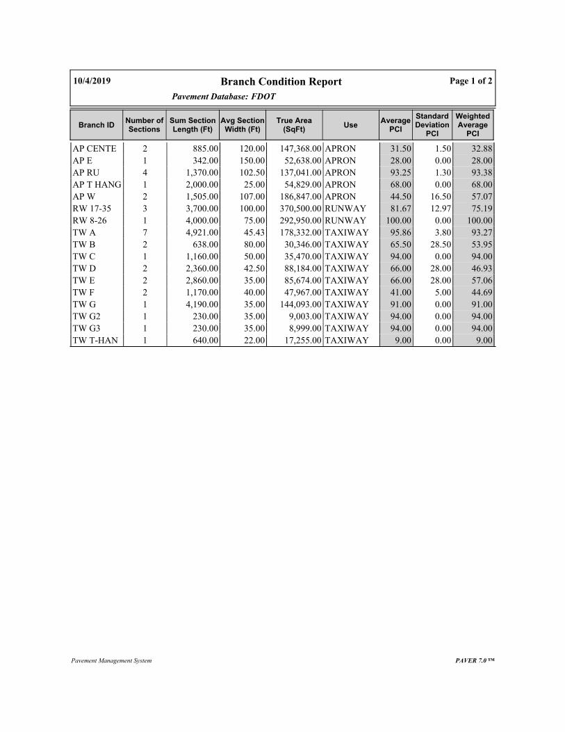
Pavement Database:
Branch Condition Report
FDOT
Page 1 of 210/4/2019
WeightedAverage
PCI
StandardDeviation
PCI
AveragePCI
UseTrue Area
(SqFt)Avg Section
Width (Ft)Sum SectionLength (Ft)
Number ofSections
Branch ID
32.881.5031.50APRON147,368.00120.00885.002AP CENTE
28.000.0028.00APRON52,638.00150.00342.001AP E
93.381.3093.25APRON137,041.00102.501,370.004AP RU
68.000.0068.00APRON54,829.0025.002,000.001AP T HANG
57.0716.5044.50APRON186,847.00107.001,505.002AP W
75.1912.9781.67RUNWAY370,500.00100.003,700.003RW 17-35
100.000.00100.00RUNWAY292,950.0075.004,000.001RW 8-26
93.273.8095.86TAXIWAY178,332.0045.434,921.007TW A
53.9528.5065.50TAXIWAY30,346.0080.00638.002TW B
94.000.0094.00TAXIWAY35,470.0050.001,160.001TW C
46.9328.0066.00TAXIWAY88,184.0042.502,360.002TW D
57.0628.0066.00TAXIWAY85,674.0035.002,860.002TW E
44.695.0041.00TAXIWAY47,967.0040.001,170.002TW F
91.000.0091.00TAXIWAY144,093.0035.004,190.001TW G
94.000.0094.00TAXIWAY9,003.0035.00230.001TW G2
94.000.0094.00TAXIWAY8,999.0035.00230.001TW G3
9.000.009.00TAXIWAY17,255.0022.00640.001TW T-HAN
Pavement Management System PAVER 7.0 ™

Pavement Database:
Branch Condition Report
FDOT
Page 2 of 210/4/2019
WeightedAverage PCI
Average STDPCI
ArithmeticAverage PCI
Total Area (SqFt)Number ofSections
Use Category
57.9028.5162.10578,723.0010APRON
86.1413.7586.25663,450.004RUNWAY
73.9728.6676.50645,323.0020TAXIWAY
73.3228.4173.411,887,496.0034ALL
Pavement Management System PAVER 7.0 ™

Section Condition Report10/4/2019 Page 1 of 2
PCIAge AtInspec
tion
LastInspection
Date
True Area(SqFt)
LanesRankUseSurfaceLast Const.
DateSection IDBranch ID
FDOT NetworkId: OMNPavement Database:
30111/28/20195,932.000TAPRONAC7/31/20084204AP CENTER
33271/28/2019141,436.000TAPRONAAC1/1/19924205AP CENTER
28351/28/201952,638.000PAPRONAC1/1/19844305AP E
9461/28/201928,383.000PAPRONAC1/1/20135110AP RU
9161/28/201928,289.000PAPRONAC1/1/20135115AP RU
9431/28/201940,182.000PAPRONAC1/1/20165120AP RU
9431/28/201940,187.000PAPRONAC1/1/20165125AP RU
68141/28/201954,829.000PAPRONAC1/1/20054410AP T HANG
28271/28/201922,255.000PAPRONAC1/1/19924102AP W
61271/28/2019164,592.000TAPRONAC1/1/19924105AP W
73111/28/2019329,912.000PRUNWAYAAC1/1/20086205RW 17-35
72111/28/201910,188.000PRUNWAYAAC1/1/20086210RW 17-35
10001/1/201930,400.000PRUNWAYAC1/1/20196215RW 17-35
10001/1/2019292,950.000SRUNWAYAC1/1/20196105RW 8-26
9361/28/2019149,004.000PTAXIWAYAC1/1/2013100TW A
10001/1/20192,434.000PTAXIWAYAC1/1/2019102TW A
9431/28/20194,550.000PTAXIWAYAAC1/1/2016105TW A
9061/28/20198,089.000PTAXIWAYAC1/1/2013110TW A
10001/1/20193,083.000PTAXIWAYAC1/1/2019112TW A
9461/28/20198,054.000PTAXIWAYAC1/1/2013115TW A
10001/1/20193,118.000PTAXIWAYAC1/1/2019117TW A
37421/28/201921,323.000PTAXIWAYAAC1/1/1977205TW B
9461/28/20199,023.000PTAXIWAYAC1/1/2013210TW B
9461/28/201935,470.000PTAXIWAYAC1/1/2013305TW C
38351/28/201974,127.000PTAXIWAYAAC1/1/1984405TW D
9461/28/201914,057.000PTAXIWAYAC1/1/2013410TW D
38291/28/201956,507.000PTAXIWAYAAC1/1/1990505TW E
9461/28/201929,167.000PTAXIWAYAC1/1/2013510TW E
46351/28/201941,694.000PTAXIWAYAC1/1/1984605TW F
36351/28/20196,273.000PTAXIWAYAC1/1/1984650TW F
9131/28/2019144,093.000PTAXIWAYAC1/1/2016700TW G
9431/28/20199,003.000PTAXIWAYAC1/1/2016705TW G2
9431/28/20198,999.000PTAXIWAYAC1/1/2016710TW G3
9271/28/201917,255.000PTAXIWAYPCC1/1/19922004TW T-HANG
PAVER 7.0 ™Pavement Management System

Section Condition Report (Summary)
WeightedAverage PCI
StandardDeviation PCI
ArithmeticAverage PCI
Number ofSections
Total Area (SqFt)Average Age at
InspectionAge Category
10/4/2019
FDOTPavement Database:
Page 2 of 2
100.000.00100.005331,985.0000-02
92.251.1293.506247,014.00303-05
93.141.4593.119309,536.00606-10
71.6517.8560.754400,861.001211-15
43.8616.7733.805402,045.002726-30
36.826.4037.004174,732.003531-35
37.000.0037.00121,323.004241-50
73.3228.4173.41341,887,496.0013ALL
PAVER 7.0 ™Pavement Management System

Appendix BAirfield Pavement Localized Maintenance and Repair and
Major Rehabilitation

Appendix B | B-1
Ormond Beach Municipal Airport (OMN)
Ta b le B- 1 Lo ca l i z ed M ai nt e n a nc e a n d Rep ai r Ne ed s b a se d o n Cu r re nt Con d i t i o n
Network ID
Branch ID Section ID Distress Code Description Severity Distress Qty Distress Unit Percent Distress Work Description Work Qty Work Unit Unit Cost Work Cost
OMN AP CENTER 4204 48 L & T CR Medium 808.92 Ft 13.6% FDOT - CRACK SEALING - AC 809.1 Ft $ 3.00 $ 2,430.00
OMN AP CENTER 4204 52 RAVELING Low 5527.59 SqFt 93.2% FDOT - SURFACE SEAL 5527.3 SqFt $ 0.55 $ 3,050.00
OMN AP CENTER 4204 52 RAVELING High 172.55 SqFt 2.9% FDOT - PATCHING - AC PARTIAL DEPTH 172.2 SqFt $ 4.00 $ 700.00
OMN AP CENTER 4205 41 ALLIGATOR CR Medium 3470.39 SqFt 2.5% FDOT - PATCHING - AC FULL DEPTH 3711.4 SqFt $ 9.00 $ 33,410.00
OMN AP CENTER 4205 43 BLOCK CR Medium 27176.94 SqFt 19.2% FDOT - CRACK SEALING - AC 8283.5 Ft $ 3.00 $ 24,860.00
OMN AP CENTER 4205 45 DEPRESSION Low 526.79 SqFt 0.4% FDOT - PATCHING - AC FULL DEPTH 623.2 SqFt $ 9.00 $ 5,610.00
OMN AP CENTER 4205 48 L & T CR Medium 3075.26 Ft 2.2% FDOT - CRACK SEALING - AC 3075.1 Ft $ 3.00 $ 9,230.00
OMN AP CENTER 4205 50 PATCHING Medium 2857.93 SqFt 2.0% FDOT - PATCHING - AC FULL DEPTH 3077.4 SqFt $ 9.00 $ 27,700.00
OMN AP CENTER 4205 50 PATCHING High 1646.34 SqFt 1.2% FDOT - PATCHING - AC FULL DEPTH 1813.7 SqFt $ 9.00 $ 16,330.00
OMN AP CENTER 4205 52 RAVELING Low 97822.53 SqFt 69.2% FDOT - SURFACE SEAL 97822.4 SqFt $ 0.55 $ 53,810.00
OMN AP CENTER 4205 52 RAVELING Medium 25188.2 SqFt 17.8% FDOT - PATCHING - AC PARTIAL DEPTH 25188.6 SqFt $ 4.00 $ 100,760.00
OMN AP CENTER 4205 52 RAVELING High 151.45 SqFt 0.1% FDOT - PATCHING - AC PARTIAL DEPTH 151.8 SqFt $ 4.00 $ 610.00
OMN AP E 4305 41 ALLIGATOR CR Low 163.83 SqFt 0.3% FDOT - PATCHING - AC FULL DEPTH 219.6 SqFt $ 9.00 $ 1,980.00
OMN AP E 4305 41 ALLIGATOR CR Medium 3021.32 SqFt 5.7% FDOT - PATCHING - AC FULL DEPTH 3246.4 SqFt $ 9.00 $ 29,220.00
OMN AP E 4305 41 ALLIGATOR CR High 29.28 SqFt 0.1% FDOT - PATCHING - AC FULL DEPTH 54.9 SqFt $ 9.00 $ 500.00
OMN AP E 4305 43 BLOCK CR Medium 28531.57 SqFt 54.2% FDOT - CRACK SEALING - AC 8696.5 Ft $ 3.00 $ 26,090.00
OMN AP E 4305 45 DEPRESSION Low 573.29 SqFt 1.1% FDOT - PATCHING - AC FULL DEPTH 673.8 SqFt $ 9.00 $ 6,070.00
OMN AP E 4305 45 DEPRESSION Medium 152.09 SqFt 0.3% FDOT - PATCHING - AC FULL DEPTH 205.6 SqFt $ 9.00 $ 1,860.00
OMN AP E 4305 50 PATCHING Medium 1181.66 SqFt 2.2% FDOT - PATCHING - AC FULL DEPTH 1324 SqFt $ 9.00 $ 11,920.00
OMN AP E 4305 52 RAVELING Low 47823.73 SqFt 90.9% FDOT - SURFACE SEAL 47824.1 SqFt $ 0.55 $ 26,310.00
OMN AP T HANG 4410 41 ALLIGATOR CR High 55.11 SqFt 0.1% FDOT - PATCHING - AC FULL DEPTH 89.3 SqFt $ 9.00 $ 810.00
OMN AP T HANG 4410 45 DEPRESSION Low 523.99 SqFt 1.0% FDOT - PATCHING - AC FULL DEPTH 620 SqFt $ 9.00 $ 5,590.00
OMN AP T HANG 4410 52 RAVELING Low 32794.84 SqFt 59.8% FDOT - SURFACE SEAL 32794.4 SqFt $ 0.55 $ 18,040.00
OMN AP T HANG 4410 52 RAVELING Medium 231.64 SqFt 0.4% FDOT - PATCHING - AC PARTIAL DEPTH 231.4 SqFt $ 4.00 $ 930.00
OMN AP W 4102 43 BLOCK CR Medium 22255.03 SqFt 100.0% FDOT - CRACK SEALING - AC 6783.5 Ft $ 3.00 $ 20,350.00
OMN AP W 4102 49 OIL SPILLAGE N/A 231.42 SqFt 1.0% FDOT - PATCHING - AC PARTIAL DEPTH 297.1 SqFt $ 4.00 $ 1,190.00
OMN AP W 4102 52 RAVELING Low 9917.54 SqFt 44.6% FDOT - SURFACE SEAL 9917.9 SqFt $ 0.55 $ 5,460.00
OMN AP W 4102 52 RAVELING Medium 66.09 SqFt 0.3% FDOT - PATCHING - AC PARTIAL DEPTH 65.7 SqFt $ 4.00 $ 270.00
OMN AP W 4105 48 L & T CR Medium 5349.25 Ft 3.3% FDOT - CRACK SEALING - AC 5349.1 Ft $ 3.00 $ 16,050.00
OMN AP W 4105 49 OIL SPILLAGE N/A 365.76 SqFt 0.2% FDOT - PATCHING - AC PARTIAL DEPTH 446.7 SqFt $ 4.00 $ 1,790.00
OMN AP W 4105 52 RAVELING Low 58521.55 SqFt 35.6% FDOT - SURFACE SEAL 58521.2 SqFt $ 0.55 $ 32,190.00
OMN AP W 4105 52 RAVELING Medium 73.19 SqFt 0.0% FDOT - PATCHING - AC PARTIAL DEPTH 73.2 SqFt $ 4.00 $ 300.00
OMN RW 17-35 6205 52 RAVELING Low 106787.79 SqFt 32.4% FDOT - SURFACE SEAL 106787.7 SqFt $ 0.55 $ 58,740.00
OMN RW 17-35 6210 52 RAVELING Low 1964.09 SqFt 19.3% FDOT - SURFACE SEAL 1964.4 SqFt $ 0.55 $ 1,090.00
OMN TW A 110 52 RAVELING Low 162.21 SqFt 2.0% FDOT - SURFACE SEAL 162.5 SqFt $ 0.55 $ 90.00
OMN TW B 205 43 BLOCK CR Medium 20714.61 SqFt 97.2% FDOT - CRACK SEALING - AC 6314 Ft $ 3.00 $ 18,950.00
OMN TW B 205 45 DEPRESSION Low 27.45 SqFt 0.1% FDOT - PATCHING - AC FULL DEPTH 52.7 SqFt $ 9.00 $ 480.00

Appendix B | B-2
Ormond Beach Municipal Airport (OMN)
Network ID
Branch ID Section ID Distress Code Description Severity Distress Qty Distress Unit Percent Distress Work Description Work Qty Work Unit Unit Cost Work Cost
OMN TW B 205 52 RAVELING Low 21322.98 SqFt 100.0% FDOT - SURFACE SEAL 21323.3 SqFt $ 0.55 $ 11,730.00
OMN TW D 405 43 BLOCK CR Medium 19641.98 SqFt 26.5% FDOT - CRACK SEALING - AC 5986.9 Ft $ 3.00 $ 17,970.00
OMN TW D 405 45 DEPRESSION Low 352.52 SqFt 0.5% FDOT - PATCHING - AC FULL DEPTH 431.6 SqFt $ 9.00 $ 3,890.00
OMN TW D 405 48 L & T CR Medium 5070.28 Ft 6.8% FDOT - CRACK SEALING - AC 5070.2 Ft $ 3.00 $ 15,220.00
OMN TW D 405 50 PATCHING Medium 836.79 SqFt 1.1% FDOT - PATCHING - AC FULL DEPTH 956.9 SqFt $ 9.00 $ 8,620.00
OMN TW D 405 52 RAVELING Low 61459.56 SqFt 82.9% FDOT - SURFACE SEAL 61459.8 SqFt $ 0.55 $ 33,810.00
OMN TW D 405 54 SHOVING High 82.34 SqFt 0.1% FDOT - PATCHING - AC FULL DEPTH 122.7 SqFt $ 9.00 $ 1,110.00
OMN TW D 405 56 SWELLING Medium 606.22 SqFt 0.8% FDOT - PATCHING - AC FULL DEPTH 709.3 SqFt $ 9.00 $ 6,390.00
OMN TW E 505 43 BLOCK CR Medium 56274.69 SqFt 99.6% FDOT - CRACK SEALING - AC 17152.6 Ft $ 3.00 $ 51,460.00
OMN TW E 505 52 RAVELING Low 56269.31 SqFt 99.6% FDOT - SURFACE SEAL 56269.4 SqFt $ 0.55 $ 30,950.00
OMN TW F 605 43 BLOCK CR Medium 8469.04 SqFt 20.3% FDOT - CRACK SEALING - AC 2581.4 Ft $ 3.00 $ 7,750.00
OMN TW F 605 48 L & T CR Medium 1136.15 Ft 2.7% FDOT - CRACK SEALING - AC 1136.2 Ft $ 3.00 $ 3,410.00
OMN TW F 605 52 RAVELING Low 41694.01 SqFt 100.0% FDOT - SURFACE SEAL 41694 SqFt $ 0.55 $ 22,940.00
OMN TW F 650 43 BLOCK CR Medium 2672.03 SqFt 42.6% FDOT - CRACK SEALING - AC 814.3 Ft $ 3.00 $ 2,450.00
OMN TW F 650 48 L & T CR Medium 27 Ft 0.4% FDOT - CRACK SEALING - AC 26.9 Ft $ 3.00 $ 90.00
OMN TW F 650 52 RAVELING Low 4519.98 SqFt 72.1% FDOT - SURFACE SEAL 4519.8 SqFt $ 0.55 $ 2,490.00
OMN TW F 650 56 SWELLING Medium 34.98 SqFt 0.6% FDOT - PATCHING - AC FULL DEPTH 62.4 SqFt $ 9.00 $ 570.00
OMN TW G 700 45 DEPRESSION Low 895.13 SqFt 0.6% FDOT - PATCHING - AC FULL DEPTH 1019.3 SqFt $ 9.00 $ 9,180.00
OMN TW T-HANG 2004 65 JT SEAL DMG High 39 Slabs 100.0% FDOT - JOINT SEAL - PCC 682.1 Ft $ 2.75 $ 1,880.00
OMN TW T-HANG 2004 72 SHAT. SLAB Low 15 Slabs 38.5% FDOT - CRACK SEALING - PCC 629.9 Ft $ 4.25 $ 2,680.00
OMN TW T-HANG 2004 72 SHAT. SLAB Medium 24 Slabs 61.5% FDOT - SLAB REPLACEMENT - PCC 10560.5 SqFt $ 30.00 $ 316,800.00

Appendix B | B-3
Ormond Beach Municipal
Airport (OMN)
Ta b le B- 2 1 0-Y e ar M aj or Reh a bi l i ta t i o n Pl a n ni n g Ne e d s at S e c t io n Le ve l
Program Year
Network ID
Branch ID Section
ID Surface
Area (SF)
PCI Before
Rehabilitation Type
Planning Cost
2020 OMN AP CENTER 4204 AC 5,932 29 AC Reconstruction $ 75,000.00
2020 OMN AP CENTER 4205 AAC 141,436 30 AC Reconstruction $ 1,768,000.00
2020 OMN AP E 4305 AC 52,638 27 AC Reconstruction $ 658,000.00
2020 OMN AP W 4102 AC 22,255 27 AC Reconstruction $ 279,000.00
2020 OMN AP W 4105 AC 164,592 60 AC Restoration $ 1,564,000.00
2020 OMN TW B 205 AAC 21,323 35 AC Reconstruction $ 267,000.00
2020 OMN TW D 405 AAC 74,127 36 AC Reconstruction $ 927,000.00
2020 OMN TW E 505 AAC 56,507 36 AC Reconstruction $ 707,000.00
2020 OMN TW F 605 AC 41,694 45 AC Restoration $ 455,000.00
2020 OMN TW F 650 AC 6,273 35 AC Reconstruction $ 79,000.00
2020 OMN TW T-HANG 2004 PCC 17,255 7 PCC Reconstruction $ 346,000.00
2022 OMN AP T HANG 4410 AC 54,829 64 AC Restoration $ 521,000.00
2027 OMN RW 17-35 6210 AAC 10,188 64 AC Restoration $ 97,000.00
2028 OMN RW 17-35 6205 AAC 329,912 64 AC Restoration $ 3,135,000.00

Appendix CTechnical Exhibits
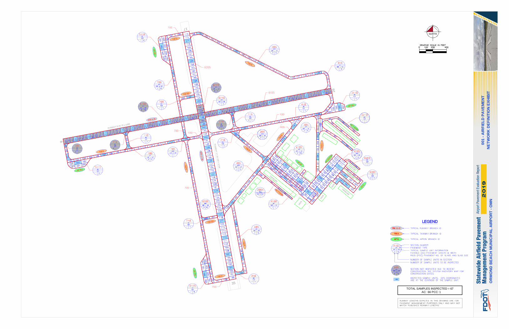
35
8
17
26
HAN
GAR
HAN
GAR
HAN
GAR
HG
R.
HG
R.
HG
R.
RUNWAY 8-26 75' x 4,005'
RU
NW
AY
17
-35
100' x
3,7
04'
TWE
TWB
TWT-H
ANG
TW
D
TW
C
TW
F
TW A
AP
CENTER
APW
AP RU
AP RU
RW
17-3
5
RW 8-26
APT
HANG
AP
RU
AP
RU
TW
G
TW G
TW G2
TW G3
TW G
HAN
GAR
HAN
GAR
AP
E
NORTH
TOTAL SAMPLES INSPECTED = 67AC: 66 PCC: 1
OR
MO
ND
BE
AC
HM
UN
ICIP
AL
AIR
PO
RT
-O
MN
NE
TW
OR
KD
EF
INIT
ION
EX
HIB
IT
001
-A
IRF
IEL
DP
AV
EM
EN
T

35
8
17
26
HAN
GAR
HAN
GAR
HAN
GAR
HG
R.
HG
R.
HG
R.
RUNWAY 8-26 75' x 4,005'
RU
NW
AY
17
-35
100' x
3,7
04'
TWE
TWB
TWT-H
ANG
TW
D
TW
C
TW
F
TW A
AP
CENTER
APW
AP RU
AP RU
RW
17-3
5
RW 8-26
APT
HANG
AP
RU
AP
RU
TW
G
TW G
TW G2
TW G3
TW G
HAN
GAR
HAN
GAR
AP
E
LEGEND
NORTH
OR
MO
ND
BE
AC
HM
UN
ICIP
AL
AIR
PO
RT
-O
MN
SY
ST
EM
INV
EN
TO
RY
EX
HIB
IT
002
-A
IRF
IEL
DP
AV
EM
EN
T
CONSTRUCTION SINCE LAST INSPECTION& ANTICIPATED CONSTRUCTION ACTIVITY

35
8
17
26
HAN
GAR
HAN
GAR
HAN
GAR
HG
R.
HG
R.
HG
R.
RUNWAY 8-26 75' x 4,005'
RU
NW
AY
17
-35
100' x
3,7
04'
TWE
TWB
TWT-H
ANG
TW
D
TW
C
TW
F
TW A
AP
CENTER
APW
AP RU
AP RU
RW
17-3
5
RW 8-26
APT
HANG
AP
RU
AP
RU
TW
G
TW G
TW G2
TW G3
TW G
HAN
GAR
HAN
GAR
AP
E
LEGEND
TW A
AP S
RW 13-31
"SECTION NO."
"PCI NO."
NORTH
OR
MO
ND
BE
AC
HM
UN
ICIP
AL
AIR
PO
RT
-O
MN
CO
ND
ITIO
NIN
DE
XE
XH
IBIT
003
-A
IRF
IEL
DP
AV
EM
EN
T
605
PCI = 46
2004
PCI = 9
6215
PCI = 100
6105
PCI = 100
117
PCI = 100
102
PCI = 100
112
PCI = 100
5125
PCI = 94
5120
PCI = 94
5110PCI = 94
105PCI = 94
115
PCI = 94
210PCI = 94
305
PCI = 94
410
PCI = 94
510
PCI = 94
705
PCI = 94
710
PCI = 94
100
PCI = 93
5115
PCI = 91
700
PCI = 91
110
PCI = 90
6205
PCI = 73
6210
PCI = 72
4410
PCI = 68
4105
PCI = 61
405
PCI = 38
505
PCI = 38
650
PCI = 36
205
PCI = 37
4205
PCI = 33
4204
PCI = 30
4305
PCI = 28
4102
PCI = 28

35
8
17
26
HAN
GAR
HAN
GAR
HAN
GAR
HG
R.
HG
R.
HG
R.
RUNWAY 8-26 75' x 4,005'
RU
NW
AY
17
-35
100' x
3,7
04'
TWE
TWB
TWT-H
ANG
TW
D
TW
C
TW
F
TW A
AP
CENTER
APW
AP RU
AP RU
RW
17-3
5
RW 8-26
APT
HANG
AP
RU
AP
RU
TW
G
TW G
TW G2
TW G3
TW G
HAN
GAR
HAN
GAR
AP
E
LEGEND
PROGRAM YEAR
"PROGRAM YEAR"
"BRANCH":"SECTION"
"REHAB ACTIVITY"
"EST. COST"
TW A
AP S
RW 13-31
NORTH
OR
MO
ND
BE
AC
HM
UN
ICIP
AL
AIR
PO
RT
-O
MN
MA
JO
RR
EH
AB
ILIT
AT
ION
EX
HIB
IT
004
-A
IRF
IEL
DP
AV
EM
EN
T
FY 2020
AP E: 4305
AC RECONSTRUCTION
$0.66 M
FY 2020AP W: 4102
AC RECONSTRUCTION
$0.28 M
FY 2020AP W: 4105
AC RESTORATION
$1.56 M
FY 2020
TW B: 205
AC RECONSTRUCTION
$0.27 M
FY 2020
TW D: 405
AC RECONSTRUCTION
$0.93 M
FY 2020
TW E: 505
AC RECONSTRUCTION
$0.71 M
FY 2020
TW F: 605
AC RESTORATION
$0.46 M
FY 2020
TW F: 650
AC RECONSTRUCTION
$0.08 M
FY 2020
TW T-HANG: 2004
PCC RECONSTRUCTION
$0.35 M
FY 2020
AP CENTER: 4205
AC RECONSTRUCTION
$1.77 M
FY 2020
AP CENTER: 4204
AC RECONSTRUCTION
$0.08 M
FY 2022
AP T HANG: 4410
AC RESTORATION
$0.52 M
FY 2027RW 17-35: 6210
AC RESTORATION
$0.1 M
FY 2028
RW 17-35: 6205
AC RESTORATION
$3.14 M

Appendix DInspection Photograph Documentation

Appendix D | D-1
Ormond Beach Municipal Airport (OMN)
RW 17-35, Section 6205, Sample Unit 159 - Low Severity (48) Longitudinal & Transverse Cracking, Low Severity (52) Raveling, Low Severity (56) Swelling, and Low Severity (57) Weathering
RW 17-35, Section 6205, Sample Unit 165 - Low Severity (52) Raveling, Low Severity (56) Swelling, and Low Severity (57) Weathering

Appendix D | D-2
Ormond Beach Municipal Airport (OMN)
TW A, Section 100, Sample Unit 107 - Low Severity (57) Weathering
TW G, Section 700, Sample Unit 115 - Low Severity (45) Depression and Low Severity (57) Weathering

Appendix D | D-3
Ormond Beach Municipal Airport (OMN)
TW D, Section 405, Sample Unit 101 - Medium Severity (43) Block Cracking and Low Severity (52) Raveling
TW E, Section 505, Sample Unit 107 - Medium Severity (43) Block Cracking and Low Severity (52) Raveling

Appendix D | D-4
Ormond Beach Municipal Airport (OMN)
TW T-HANG, Section 2004, Sample Unit 602 - High Severity (65) Joint Seal Damage and Low Severity (72) Shattered Slab
AP CENTER, Section 4205, Sample Unit 111 - Low Severity (48) Longitudinal & Transverse Cracking, Low Severity (50) Patching,
Low Severity (52) Raveling, and Medium Severity (52) Raveling

Appendix D | D-5
Ormond Beach Municipal Airport (OMN)
AP E, Section 4305, Sample Unit 101 - Medium Severity (41) Alligator Cracking, High Severity (41) Alligator Cracking, and Low Severity (52) Raveling

Appendix EInspection Distress Details
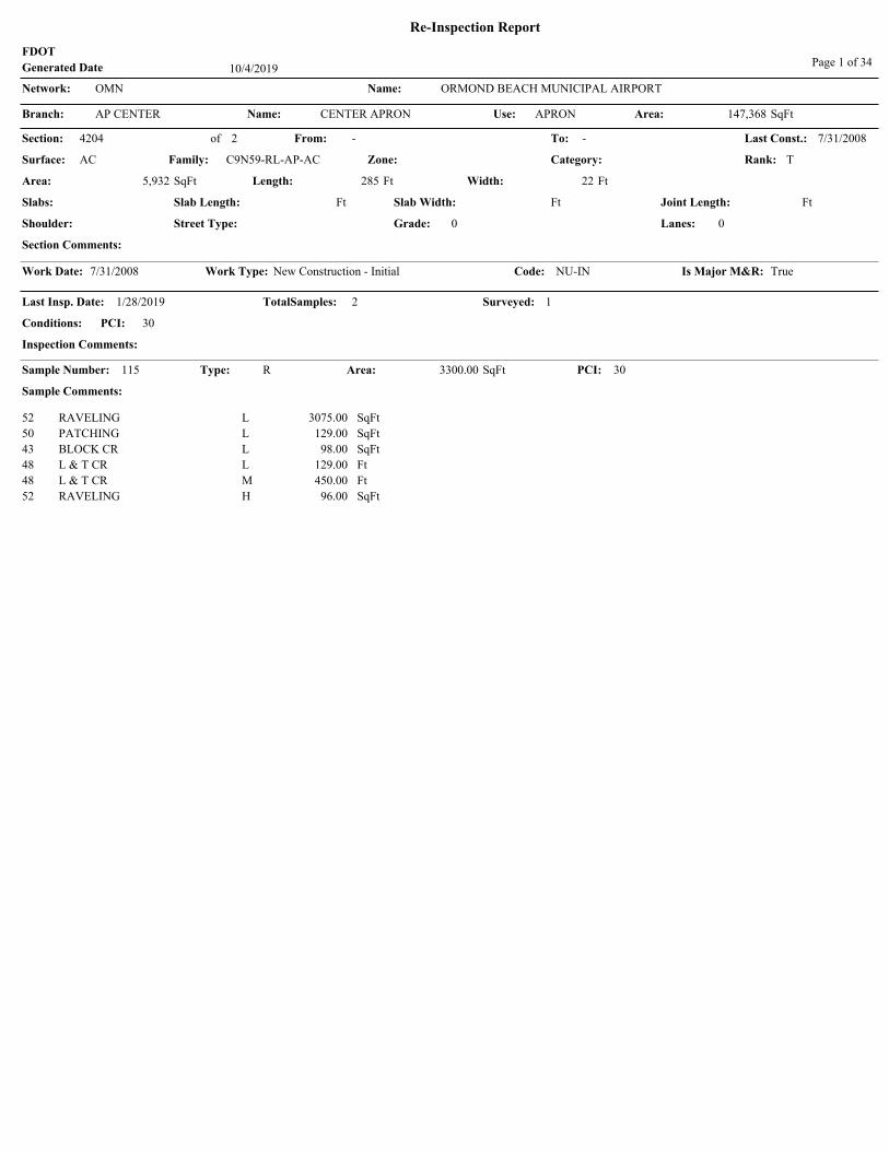
FDOT
Re-Inspection Report
10/4/2019Generated Date Page 1 of 34
OMNNetwork: Name: ORMOND BEACH MUNICIPAL AIRPORT
Name: CENTER APRONAP CENTERBranch: Use: Area: SqFtAPRON 147,368
Section: To: Last Const.:
Length: 285
C9N59-RL-AP-AC
SqFt
Surface: AC
4204 of From:
Ft
Category:Zone: TRank:
Area: 22
Slabs:
Ft5,932 Width:
Ft FtSlab Length: Joint Length:
Street Type: Lanes: 0Shoulder:
7/31/20082
Family:
- -
Grade:
Slab Width: Ft
0
Section Comments:
Work Date: Is Major M&R:Code:Work Type:7/31/2008 New Construction - Initial NU-IN True
1/28/2019
PCI:
Last Insp. Date: TotalSamples: 2
Inspection Comments:
30
Surveyed:
Conditions:
1
115 Area:Sample Number: Type: R 3300.00
Sample Comments:
PCI:SqFt 30
52 RAVELING L 3075.00 SqFt
50 PATCHING L 129.00 SqFt
43 BLOCK CR L 98.00 SqFt
48 L & T CR L 129.00 Ft
48 L & T CR M 450.00 Ft
52 RAVELING H 96.00 SqFt

OMNNetwork: Name: ORMOND BEACH MUNICIPAL AIRPORT
Name: CENTER APRONAP CENTERBranch: Use: Area: SqFtAPRON 147,368
Section: To: Last Const.:
Length: 600
C9N59-RL-AP-AAC-APC
SqFt
Surface: AAC
4205 of From:
Ft
Category:Zone: TRank:
Area: 218
Slabs:
Ft141,436 Width:
Ft FtSlab Length: Joint Length:
Street Type: Lanes: 0Shoulder:
1/1/19922
Family:
- -
Grade:
Slab Width: Ft
0
Section Comments:
Work Date: Is Major M&R:Code:Work Type:1/1/1979 BUILT IMPORTED True
Work Date: Is Major M&R:Code:Work Type:1/1/1992 OVERLAY IMPORTED True
1/28/2019
PCI:
Last Insp. Date: TotalSamples: 26
Inspection Comments:
33
Surveyed:
Conditions:
4
102 Area:Sample Number: Type: R 5452.00
Sample Comments:
PCI:SqFt 42
52 RAVELING L 5161.00 SqFt
50 PATCHING H 250.00 SqFt
52 RAVELING H 17.00 SqFt
52 RAVELING M 24.00 SqFt
48 L & T CR L 283.00 Ft
48 L & T CR M 250.00 Ft
111 Area:Sample Number: Type: R 6024.00
Sample Comments:
PCI:SqFt 17
43 BLOCK CR L 660.00 SqFt
41 ALLIGATOR CR M 527.00 SqFt
50 PATCHING L 452.00 SqFt
52 RAVELING L 2400.00 SqFt
48 L & T CR L 50.00 Ft
45 DEPRESSION L 80.00 SqFt
52 RAVELING M 1600.00 SqFt
43 BLOCK CR M 2621.00 SqFt
205 Area:Sample Number: Type: R 5001.00
Sample Comments:
PCI:SqFt 42
52 RAVELING H 6.00 SqFt
50 PATCHING L 67.00 SqFt
48 L & T CR M 217.00 Ft
50 PATCHING M 434.00 SqFt
43 BLOCK CR M 256.00 SqFt
52 RAVELING L 4494.00 SqFt
48 L & T CR L 80.00 Ft
209 Area:Sample Number: Type: R 5001.00
Sample Comments:
PCI:SqFt 32
52 RAVELING L 2800.00 SqFt
43 BLOCK CR L 3751.00 SqFt
52 RAVELING M 2201.00 SqFt
43 BLOCK CR M 1250.00 SqFt

OMNNetwork: Name: ORMOND BEACH MUNICIPAL AIRPORT
Name: EAST APRON - HANGARAREA
AP EBranch: Use: Area: SqFtAPRON 52,638
Section: To: Last Const.:
Length: 342
C9N59-RL-AP-AC
SqFt
Surface: AC
4305 of From:
Ft
Category:Zone: PRank:
Area: 150
Slabs:
Ft52,638 Width:
Ft FtSlab Length: Joint Length:
Street Type: Lanes: 0Shoulder:
1/1/19841
Family:
- -
Grade:
Slab Width: Ft
0
Section Comments:
Work Date: Is Major M&R:Code:Work Type:1/1/1984 BUILT IMPORTED True
1/28/2019
PCI:
Last Insp. Date: TotalSamples: 11
Inspection Comments:
28
Surveyed:
Conditions:
3
101 Area:Sample Number: Type: R 6927.00
Sample Comments:
PCI:SqFt 17
43 BLOCK CR M 4254.00 SqFt
45 DEPRESSION L 50.00 SqFt
50 PATCHING M 400.00 SqFt
52 RAVELING L 5297.00 SqFt
50 PATCHING L 1230.00 SqFt
41 ALLIGATOR CR H 10.00 SqFt
41 ALLIGATOR CR M 1033.00 SqFt
45 DEPRESSION M 52.00 SqFt
102 Area:Sample Number: Type: R 6156.00
Sample Comments:
PCI:SqFt 32
50 PATCHING M 4.00 SqFt
43 BLOCK CR L 3050.00 SqFt
43 BLOCK CR M 3050.00 SqFt
45 DEPRESSION L 130.00 SqFt
52 RAVELING L 6152.00 SqFt
41 ALLIGATOR CR L 56.00 SqFt
201 Area:Sample Number: Type: R 4914.00
Sample Comments:
PCI:SqFt 38
52 RAVELING L 4902.00 SqFt
43 BLOCK CR M 2451.00 SqFt
43 BLOCK CR L 2451.00 SqFt
50 PATCHING L 12.00 SqFt
45 DEPRESSION L 16.00 SqFt

OMNNetwork: Name: ORMOND BEACH MUNICIPAL AIRPORT
Name: RUN-UP APRONAP RUBranch: Use: Area: SqFtAPRON 137,041
Section: To: Last Const.:
Length: 300
C9N59-RL-AP-AC
SqFt
Surface: AC
5110 of From:
Ft
Category:Zone: PRank:
Area: 100
Slabs:
Ft28,383 Width:
Ft FtSlab Length: Joint Length:
Street Type: Lanes: 0Shoulder:
1/1/20134
Family:
- -
Grade:
Slab Width: Ft
0
Section Comments:
Work Date: Is Major M&R:Code:Work Type:1/1/2013 New Construction - Initial NU-IN True
1/28/2019
PCI:
Last Insp. Date: TotalSamples: 5
Inspection Comments:
94
Surveyed:
Conditions:
1
501 Area:Sample Number: Type: R 6227.00
Sample Comments:
PCI:SqFt 94
57 WEATHERING L 6227.00 SqFt

OMNNetwork: Name: ORMOND BEACH MUNICIPAL AIRPORT
Name: RUN-UP APRONAP RUBranch: Use: Area: SqFtAPRON 137,041
Section: To: Last Const.:
Length: 300
C9N59-RL-AP-AC
SqFt
Surface: AC
5115 of From:
Ft
Category:Zone: PRank:
Area: 100
Slabs:
Ft28,289 Width:
Ft FtSlab Length: Joint Length:
Street Type: Lanes: 0Shoulder:
1/1/20134
Family:
- -
Grade:
Slab Width: Ft
0
Section Comments:
Work Date: Is Major M&R:Code:Work Type:1/1/2013 New Construction - Initial NU-IN True
1/28/2019
PCI:
Last Insp. Date: TotalSamples: 6
Inspection Comments:
91
Surveyed:
Conditions:
1
501 Area:Sample Number: Type: R 5000.00
Sample Comments:
PCI:SqFt 91
57 WEATHERING L 5000.00 SqFt
48 L & T CR L 7.00 Ft

OMNNetwork: Name: ORMOND BEACH MUNICIPAL AIRPORT
Name: RUN-UP APRONAP RUBranch: Use: Area: SqFtAPRON 137,041
Section: To: Last Const.:
Length: 385
C9N59-RL-AP-AC
SqFt
Surface: AC
5120 of From:
Ft
Category:Zone: PRank:
Area: 105
Slabs:
Ft40,182 Width:
Ft FtSlab Length: Joint Length:
Street Type: Lanes: 0Shoulder:
1/1/20164
Family:
- -
Grade:
Slab Width: Ft
0
Section Comments:
Work Date: Is Major M&R:Code:Work Type:1/1/2016 New Construction - AC NC-AC True
1/28/2019
PCI:
Last Insp. Date: TotalSamples: 8
Inspection Comments:
94
Surveyed:
Conditions:
1
502 Area:Sample Number: Type: R 5500.00
Sample Comments:
PCI:SqFt 94
57 WEATHERING L 5500.00 SqFt

OMNNetwork: Name: ORMOND BEACH MUNICIPAL AIRPORT
Name: RUN-UP APRONAP RUBranch: Use: Area: SqFtAPRON 137,041
Section: To: Last Const.:
Length: 385
C9N59-RL-AP-AC
SqFt
Surface: AC
5125 of From:
Ft
Category:Zone: PRank:
Area: 105
Slabs:
Ft40,187 Width:
Ft FtSlab Length: Joint Length:
Street Type: Lanes: 0Shoulder:
1/1/20164
Family:
- -
Grade:
Slab Width: Ft
0
Section Comments:
Work Date: Is Major M&R:Code:Work Type:1/1/2016 New Construction - AC NC-AC True
1/28/2019
PCI:
Last Insp. Date: TotalSamples: 8
Inspection Comments:
94
Surveyed:
Conditions:
1
505 Area:Sample Number: Type: R 5500.00
Sample Comments:
PCI:SqFt 94
57 WEATHERING L 5500.00 SqFt

OMNNetwork: Name: ORMOND BEACH MUNICIPAL AIRPORT
Name: AP T HANGAP T HANGBranch: Use: Area: SqFtAPRON 54,829
Section: To: Last Const.:
Length: 2,000
C9N59-RL-AP-AC
SqFt
Surface: AC
4410 of From:
Ft
Category:Zone: PRank:
Area: 25
Slabs:
Ft54,829 Width:
Ft FtSlab Length: Joint Length:
Street Type: Lanes: 0Shoulder:
1/1/20051
Family:
- -
Grade:
Slab Width: Ft
0
Section Comments:
Work Date: Is Major M&R:Code:Work Type:1/1/2005 New Construction - AC NC-AC True
1/28/2019
PCI:
Last Insp. Date: TotalSamples: 11
Inspection Comments:
68
Surveyed:
Conditions:
2
102 Area:Sample Number: Type: R 4941.00
Sample Comments:
PCI:SqFt 82
52 RAVELING L 988.00 SqFt
48 L & T CR L 21.00 Ft
303 Area:Sample Number: Type: R 5000.00
Sample Comments:
PCI:SqFt 54
41 ALLIGATOR CR H 10.00 SqFt
45 DEPRESSION L 95.00 SqFt
52 RAVELING L 4958.00 SqFt
48 L & T CR L 63.00 Ft
52 RAVELING M 42.00 SqFt

OMNNetwork: Name: ORMOND BEACH MUNICIPAL AIRPORT
Name: WEST APRONAP WBranch: Use: Area: SqFtAPRON 186,847
Section: To: Last Const.:
Length: 670
C9N59-RL-AP-AC
SqFt
Surface: AC
4102 of From:
Ft
Category:Zone: PRank:
Area: 34
Slabs:
Ft22,255 Width:
Ft FtSlab Length: Joint Length:
Street Type: Lanes: 0Shoulder:
1/1/19922
Family:
- -
Grade:
Slab Width: Ft
0
Section Comments:
Work Date: Is Major M&R:Code:Work Type:1/1/1992 BUILT IMPORTED True
1/28/2019
PCI:
Last Insp. Date: TotalSamples: 7
Inspection Comments:
28
Surveyed:
Conditions:
1
101 Area:Sample Number: Type: R 3366.00
Sample Comments:
PCI:SqFt 28
52 RAVELING L 1500.00 SqFt
49 OIL SPILLAGE N 35.00 SqFt
43 BLOCK CR M 3366.00 SqFt
52 RAVELING M 10.00 SqFt
56 SWELLING L 815.00 SqFt

OMNNetwork: Name: ORMOND BEACH MUNICIPAL AIRPORT
Name: WEST APRONAP WBranch: Use: Area: SqFtAPRON 186,847
Section: To: Last Const.:
Length: 835
C9N59-RL-AP-AC
SqFt
Surface: AC
4105 of From:
Ft
Category:Zone: TRank:
Area: 180
Slabs:
Ft164,592 Width:
Ft FtSlab Length: Joint Length:
Street Type: Lanes: 0Shoulder:
1/1/19922
Family:
- -
Grade:
Slab Width: Ft
0
Section Comments:
Work Date: Is Major M&R:Code:Work Type:1/1/1992 BUILT IMPORTED True
1/28/2019
PCI:
Last Insp. Date: TotalSamples: 39
Inspection Comments:
61
Surveyed:
Conditions:
4
102 Area:Sample Number: Type: R 5000.00
Sample Comments:
PCI:SqFt 64
57 WEATHERING L 3400.00 SqFt
52 RAVELING L 1600.00 SqFt
48 L & T CR L 395.00 Ft
48 L & T CR M 130.00 Ft
205 Area:Sample Number: Type: R 5000.00
Sample Comments:
PCI:SqFt 63
52 RAVELING M 8.00 SqFt
49 OIL SPILLAGE N 24.00 SqFt
48 L & T CR M 144.00 Ft
48 L & T CR L 300.00 Ft
52 RAVELING L 1492.00 SqFt
307 Area:Sample Number: Type: R 5000.00
Sample Comments:
PCI:SqFt 57
52 RAVELING L 1458.00 SqFt
50 PATCHING L 42.00 SqFt
48 L & T CR L 401.00 Ft
48 L & T CR M 181.00 Ft
49 OIL SPILLAGE N 16.00 SqFt
57 WEATHERING L 3500.00 SqFt
403 Area:Sample Number: Type: R 3000.00
Sample Comments:
PCI:SqFt 59
48 L & T CR L 195.00 Ft
57 WEATHERING L 1150.00 SqFt
48 L & T CR M 130.00 Ft
52 RAVELING L 1850.00 SqFt

OMNNetwork: Name: ORMOND BEACH MUNICIPAL AIRPORT
Name: RUNWAY 17-35RW 17-35Branch: Use: Area: SqFtRUNWAY 370,500
Section: To: Last Const.:
Length: 3,300
C9N59-RL-RW-AAC-APC
SqFt
Surface: AAC
6205 of From:
Ft
Category:Zone: PRank:
Area: 100
Slabs:
Ft329,912 Width:
Ft FtSlab Length: Joint Length:
Street Type: Lanes: 0Shoulder:
1/1/20083
Family:
- -
Grade:
Slab Width: Ft
0
Section Comments:
Work Date: Is Major M&R:Code:Work Type:1/1/1943 BUILT IMPORTED True
Work Date: Is Major M&R:Code:Work Type:1/1/1983 OVERLAY IMPORTED True
Work Date: Is Major M&R:Code:Work Type:1/1/2008 Mill and Overlay ML-OL True
1/28/2019
PCI:
Last Insp. Date: TotalSamples: 66
Inspection Comments:
73
Surveyed:
Conditions:
14
103 Area:Sample Number: Type: R 5000.00
Sample Comments:
PCI:SqFt 78
57 WEATHERING L 3300.00 SqFt
52 RAVELING L 1700.00 SqFt
107 Area:Sample Number: Type: R 5000.00
Sample Comments:
PCI:SqFt 74
57 WEATHERING L 3400.00 SqFt
48 L & T CR L 36.00 Ft
52 RAVELING L 1600.00 SqFt
112 Area:Sample Number: Type: R 5000.00
Sample Comments:
PCI:SqFt 76
52 RAVELING L 1100.00 SqFt
48 L & T CR L 112.00 Ft
57 WEATHERING L 3900.00 SqFt
117 Area:Sample Number: Type: R 5000.00
Sample Comments:
PCI:SqFt 73
52 RAVELING L 1600.00 SqFt
48 L & T CR L 95.00 Ft
57 WEATHERING L 3400.00 SqFt
119 Area:Sample Number: Type: R 5000.00
Sample Comments:
PCI:SqFt 73
57 WEATHERING L 3400.00 SqFt
52 RAVELING L 1600.00 SqFt
48 L & T CR L 88.00 Ft
126 Area:Sample Number: Type: R 5000.00
Sample Comments:
PCI:SqFt 73
52 RAVELING L 1600.00 SqFt
48 L & T CR L 71.00 Ft
57 WEATHERING L 3400.00 SqFt
131 Area:Sample Number: Type: R 5000.00
Sample Comments:
PCI:SqFt 77
48 L & T CR L 17.00 Ft
52 RAVELING L 1100.00 SqFt
57 WEATHERING L 3900.00 SqFt
135 Area:Sample Number: Type: R 5000.00
Sample Comments:
PCI:SqFt 73
57 WEATHERING L 3400.00 SqFt

48 L & T CR L 55.00 Ft
52 RAVELING L 1600.00 SqFt
139 Area:Sample Number: Type: R 5000.00
Sample Comments:
PCI:SqFt 73
48 L & T CR L 64.00 Ft
57 WEATHERING L 3400.00 SqFt
52 RAVELING L 1600.00 SqFt
142 Area:Sample Number: Type: R 5000.00
Sample Comments:
PCI:SqFt 72
48 L & T CR L 42.00 Ft
56 SWELLING L 16.00 SqFt
57 WEATHERING L 3400.00 SqFt
52 RAVELING L 1600.00 SqFt
153 Area:Sample Number: Type: R 5000.00
Sample Comments:
PCI:SqFt 70
56 SWELLING L 45.00 SqFt
57 WEATHERING L 3042.00 SqFt
48 L & T CR L 14.00 Ft
52 RAVELING L 1958.00 SqFt
159 Area:Sample Number: Type: R 5000.00
Sample Comments:
PCI:SqFt 68
48 L & T CR L 65.00 Ft
56 SWELLING L 375.00 SqFt
52 RAVELING L 1600.00 SqFt
57 WEATHERING L 3400.00 SqFt
165 Area:Sample Number: Type: R 5000.00
Sample Comments:
PCI:SqFt 67
48 L & T CR L 21.00 Ft
52 RAVELING L 2100.00 SqFt
57 WEATHERING L 2900.00 SqFt
56 SWELLING L 625.00 SqFt
171 Area:Sample Number: Type: R 5000.00
Sample Comments:
PCI:SqFt 72
57 WEATHERING L 3100.00 SqFt
56 SWELLING L 130.00 SqFt
52 RAVELING L 1900.00 SqFt

OMNNetwork: Name: ORMOND BEACH MUNICIPAL AIRPORT
Name: RUNWAY 17-35RW 17-35Branch: Use: Area: SqFtRUNWAY 370,500
Section: To: Last Const.:
Length: 100
C9N59-RL-RW-AAC-APC
SqFt
Surface: AAC
6210 of From:
Ft
Category:Zone: PRank:
Area: 100
Slabs:
Ft10,188 Width:
Ft FtSlab Length: Joint Length:
Street Type: Lanes: 0Shoulder:
1/1/20083
Family:
- -
Grade:
Slab Width: Ft
0
Section Comments:
Work Date: Is Major M&R:Code:Work Type:1/1/1943 BUILT IMPORTED True
Work Date: Is Major M&R:Code:Work Type:1/1/1973 OVERLAY IMPORTED True
Work Date: Is Major M&R:Code:Work Type:1/1/2008 Mill and Overlay ML-OL True
1/28/2019
PCI:
Last Insp. Date: TotalSamples: 2
Inspection Comments:
72
Surveyed:
Conditions:
1
145 Area:Sample Number: Type: R 5187.00
Sample Comments:
PCI:SqFt 72
56 SWELLING L 150.00 SqFt
48 L & T CR L 58.00 Ft
52 RAVELING L 1000.00 SqFt
57 WEATHERING L 4000.00 SqFt

OMNNetwork: Name: ORMOND BEACH MUNICIPAL AIRPORT
Name: RUNWAY 17-35RW 17-35Branch: Use: Area: SqFtRUNWAY 370,500
Section: To: Last Const.:
Length: 300
C9N59-RL-RW-AC
SqFt
Surface: AC
6215 of From:
Ft
Category:Zone: PRank:
Area: 100
Slabs:
Ft30,400 Width:
Ft FtSlab Length: Joint Length:
Street Type: Lanes: 0Shoulder:
1/1/20193
Family:
- -
Grade:
Slab Width: Ft
0
Section Comments:
Work Date: Is Major M&R:Code:Work Type:1/1/1943 BUILT IMPORTED True
Work Date: Is Major M&R:Code:Work Type:1/1/1973 OVERLAY IMPORTED True
Work Date: Is Major M&R:Code:Work Type:1/1/2008 Mill and Overlay ML-OL True
Work Date: Is Major M&R:Code:Work Type:1/1/2019 Complete Reconstruction - AC CR-AC True
12/4/2014
PCI:
Last Insp. Date: TotalSamples: 6
Inspection Comments:
74
Surveyed:
Conditions:
2
NOTE: *** Pre-Construction PCI ***
146 Area:Sample Number: Type: R 5000.00
Sample Comments:
PCI:SqFt 76
57 WEATHERING L 3500.00 SqFt
48 LONGITUDINAL/TRANSVERSECRACKING
L 4.00 Ft
52 RAVELING L 1500.00 SqFt
148 Area:Sample Number: Type: R 5000.00
Sample Comments:
PCI:SqFt 72
56 SWELLING L 22.00 SqFt
57 WEATHERING L 3500.00 SqFt
52 RAVELING L 1500.00 SqFt
48 LONGITUDINAL/TRANSVERSECRACKING
L 88.00 Ft

OMNNetwork: Name: ORMOND BEACH MUNICIPAL AIRPORT
Name: RUNWAY 8-26RW 8-26Branch: Use: Area: SqFtRUNWAY 292,950
Section: To: Last Const.:
Length: 4,000
C9N59-RL-RW-AC
SqFt
Surface: AC
6105 of From:
Ft
Category:Zone: SRank:
Area: 75
Slabs:
Ft292,950 Width:
Ft FtSlab Length: Joint Length:
Street Type: Lanes: 0Shoulder:
1/1/20191
Family:
- -
Grade:
Slab Width: Ft
0
Section Comments:
Work Date: Is Major M&R:Code:Work Type:1/1/1943 BUILT IMPORTED True
Work Date: Is Major M&R:Code:Work Type:1/1/1977 OVERLAY IMPORTED True
Work Date: Is Major M&R:Code:Work Type:1/1/2019 Complete Reconstruction - AC CR-AC True
12/4/2014
PCI:
Last Insp. Date: TotalSamples: 78
Inspection Comments:
67
Surveyed:
Conditions:
16
NOTE: *** Pre-Construction PCI ***
103 Area:Sample Number: Type: R 3750.00
Sample Comments:
PCI:SqFt 69
48 LONGITUDINAL/TRANSVERSECRACKING
L 307.00 Ft
52 RAVELING L 3750.00 SqFt
107 Area:Sample Number: Type: R 3750.00
Sample Comments:
PCI:SqFt 69
48 LONGITUDINAL/TRANSVERSECRACKING
L 182.00 Ft
52 RAVELING L 3750.00 SqFt
112 Area:Sample Number: Type: R 3750.00
Sample Comments:
PCI:SqFt 64
48 LONGITUDINAL/TRANSVERSECRACKING
L 138.00 Ft
52 RAVELING L 3750.00 SqFt
48 LONGITUDINAL/TRANSVERSECRACKING
M 15.00 Ft
117 Area:Sample Number: Type: R 3750.00
Sample Comments:
PCI:SqFt 69
52 RAVELING L 3750.00 SqFt
48 LONGITUDINAL/TRANSVERSECRACKING
L 169.00 Ft
120 Area:Sample Number: Type: R 3750.00
Sample Comments:
PCI:SqFt 69
52 RAVELING L 3750.00 SqFt
48 LONGITUDINAL/TRANSVERSECRACKING
L 222.00 Ft
124 Area:Sample Number: Type: R 3750.00
Sample Comments:
PCI:SqFt 64
52 RAVELING L 3750.00 SqFt
48 LONGITUDINAL/TRANSVERSECRACKING
L 182.00 Ft
48 LONGITUDINAL/TRANSVERSECRACKING
M 11.00 Ft
128 Area:Sample Number: Type: R 3750.00
Sample Comments:
PCI:SqFt 67
52 RAVELING L 3750.00 SqFt
48 LONGITUDINAL/TRANSVERSECRACKING
L 229.00 Ft
56 SWELLING L 22.00 SqFt

131 Area:Sample Number: Type: R 3750.00
Sample Comments:
PCI:SqFt 69
48 LONGITUDINAL/TRANSVERSECRACKING
L 58.00 Ft
48 LONGITUDINAL/TRANSVERSECRACKING
L 100.00 Ft
52 RAVELING L 3750.00 SqFt
136 Area:Sample Number: Type: R 3750.00
Sample Comments:
PCI:SqFt 69
52 RAVELING L 3750.00 SqFt
48 LONGITUDINAL/TRANSVERSECRACKING
L 21.00 Ft
48 LONGITUDINAL/TRANSVERSECRACKING
L 250.00 Ft
146 Area:Sample Number: Type: R 3750.00
Sample Comments:
PCI:SqFt 69
48 LONGITUDINAL/TRANSVERSECRACKING
L 168.00 Ft
52 RAVELING L 3750.00 SqFt
151 Area:Sample Number: Type: R 3750.00
Sample Comments:
PCI:SqFt 69
48 LONGITUDINAL/TRANSVERSECRACKING
L 177.00 Ft
52 RAVELING L 3750.00 SqFt
155 Area:Sample Number: Type: R 3750.00
Sample Comments:
PCI:SqFt 69
48 LONGITUDINAL/TRANSVERSECRACKING
L 124.00 Ft
52 RAVELING L 3750.00 SqFt
48 LONGITUDINAL/TRANSVERSECRACKING
L 100.00 Ft
161 Area:Sample Number: Type: R 3750.00
Sample Comments:
PCI:SqFt 67
48 LONGITUDINAL/TRANSVERSECRACKING
L 209.00 Ft
56 SWELLING L 8.00 SqFt
52 RAVELING L 3750.00 SqFt
166 Area:Sample Number: Type: R 3750.00
Sample Comments:
PCI:SqFt 64
52 RAVELING L 3750.00 SqFt
48 LONGITUDINAL/TRANSVERSECRACKING
L 92.00 Ft
48 LONGITUDINAL/TRANSVERSECRACKING
M 20.00 Ft
172 Area:Sample Number: Type: R 3750.00
Sample Comments:
PCI:SqFt 69
52 RAVELING L 3750.00 SqFt
48 LONGITUDINAL/TRANSVERSECRACKING
L 187.00 Ft
177 Area:Sample Number: Type: R 3750.00
Sample Comments:
PCI:SqFt 69
48 LONGITUDINAL/TRANSVERSECRACKING
L 218.00 Ft
52 RAVELING L 3750.00 SqFt

OMNNetwork: Name: ORMOND BEACH MUNICIPAL AIRPORT
Name: TAXIWAY ATW ABranch: Use: Area: SqFtTAXIWAY 178,332
Section: To: Last Const.:
Length: 4,250
C9N59-RL-TW-AC
SqFt
Surface: AC
100 of From:
Ft
Category:Zone: PRank:
Area: 35
Slabs:
Ft149,004 Width:
Ft FtSlab Length: Joint Length:
Street Type: Lanes: 0Shoulder:
1/1/20137
Family:
- -
Grade:
Slab Width: Ft
0
Section Comments:
Work Date: Is Major M&R:Code:Work Type:1/1/2013 New Construction - Initial NU-IN True
1/28/2019
PCI:
Last Insp. Date: TotalSamples: 41
Inspection Comments:
93
Surveyed:
Conditions:
5
101 Area:Sample Number: Type: R 3939.00
Sample Comments:
PCI:SqFt 90
48 L & T CR L 18.00 Ft
57 WEATHERING L 3939.00 SqFt
107 Area:Sample Number: Type: R 3500.00
Sample Comments:
PCI:SqFt 94
57 WEATHERING L 3500.00 SqFt
117 Area:Sample Number: Type: R 3500.00
Sample Comments:
PCI:SqFt 94
57 WEATHERING L 3500.00 SqFt
127 Area:Sample Number: Type: R 3500.00
Sample Comments:
PCI:SqFt 94
57 WEATHERING L 3500.00 SqFt
138 Area:Sample Number: Type: R 3500.00
Sample Comments:
PCI:SqFt 94
57 WEATHERING L 3500.00 SqFt

OMNNetwork: Name: ORMOND BEACH MUNICIPAL AIRPORT
Name: TAXIWAY ATW ABranch: Use: Area: SqFtTAXIWAY 178,332
Section: To: Last Const.:
Length: 130
C9N59-RL-TW-AAC-APC
SqFt
Surface: AAC
105 of From:
Ft
Category:Zone: PRank:
Area: 35
Slabs:
Ft4,550 Width:
Ft FtSlab Length: Joint Length:
Street Type: Lanes: 0Shoulder:
1/1/20167
Family:
- -
Grade:
Slab Width: Ft
0
Section Comments:
Work Date: Is Major M&R:Code:Work Type:1/1/2013 New Construction - Initial NU-IN True
Work Date: Is Major M&R:Code:Work Type:1/1/2016 MILL and OVERLAY ML-OV True
1/28/2019
PCI:
Last Insp. Date: TotalSamples: 1
Inspection Comments:
94
Surveyed:
Conditions:
1
119 Area:Sample Number: Type: R 4550.00
Sample Comments:
PCI:SqFt 94
57 WEATHERING L 4550.00 SqFt

OMNNetwork: Name: ORMOND BEACH MUNICIPAL AIRPORT
Name: TAXIWAY ATW ABranch: Use: Area: SqFtTAXIWAY 178,332
Section: To: Last Const.:
Length: 194
C9N59-RL-TW-AC
SqFt
Surface: AC
110 of From:
Ft
Category:Zone: PRank:
Area: 40
Slabs:
Ft8,089 Width:
Ft FtSlab Length: Joint Length:
Street Type: Lanes: 0Shoulder:
1/1/20137
Family:
- -
Grade:
Slab Width: Ft
0
Section Comments:
Work Date: Is Major M&R:Code:Work Type:1/1/2013 New Construction - Initial NU-IN True
1/28/2019
PCI:
Last Insp. Date: TotalSamples: 2
Inspection Comments:
90
Surveyed:
Conditions:
1
201 Area:Sample Number: Type: R 4588.00
Sample Comments:
PCI:SqFt 90
52 RAVELING L 92.00 SqFt
57 WEATHERING L 4496.00 SqFt

OMNNetwork: Name: ORMOND BEACH MUNICIPAL AIRPORT
Name: TAXIWAY ATW ABranch: Use: Area: SqFtTAXIWAY 178,332
Section: To: Last Const.:
Length: 193
C9N59-RL-TW-AC
SqFt
Surface: AC
115 of From:
Ft
Category:Zone: PRank:
Area: 40
Slabs:
Ft8,054 Width:
Ft FtSlab Length: Joint Length:
Street Type: Lanes: 0Shoulder:
1/1/20137
Family:
- -
Grade:
Slab Width: Ft
0
Section Comments:
Work Date: Is Major M&R:Code:Work Type:1/1/2013 New Construction - Initial NU-IN True
1/28/2019
PCI:
Last Insp. Date: TotalSamples: 2
Inspection Comments:
94
Surveyed:
Conditions:
1
200 Area:Sample Number: Type: R 3500.00
Sample Comments:
PCI:SqFt 94
57 WEATHERING L 3500.00 SqFt

OMNNetwork: Name: ORMOND BEACH MUNICIPAL AIRPORT
Name: TAXIWAY BTW BBranch: Use: Area: SqFtTAXIWAY 30,346
Section: To: Last Const.:
Length: 495
C9N59-RL-TW-AAC-APC
SqFt
Surface: AAC
205 of From:
Ft
Category:Zone: PRank:
Area: 40
Slabs:
Ft21,323 Width:
Ft FtSlab Length: Joint Length:
Street Type: Lanes: 0Shoulder:
1/1/19772
Family:
- -
Grade:
Slab Width: Ft
0
Section Comments:
Work Date: Is Major M&R:Code:Work Type:1/1/1943 BUILT IMPORTED True
Work Date: Is Major M&R:Code:Work Type:1/1/1977 OVERLAY IMPORTED True
1/28/2019
PCI:
Last Insp. Date: TotalSamples: 5
Inspection Comments:
37
Surveyed:
Conditions:
2
101 Area:Sample Number: Type: R 5323.00
Sample Comments:
PCI:SqFt 37
43 BLOCK CR M 5057.00 SqFt
56 SWELLING L 275.00 SqFt
45 DEPRESSION L 12.00 SqFt
52 RAVELING L 5323.00 SqFt
105 Area:Sample Number: Type: R 4000.00
Sample Comments:
PCI:SqFt 37
56 SWELLING L 350.00 SqFt
52 RAVELING L 4000.00 SqFt
43 BLOCK CR M 4000.00 SqFt

OMNNetwork: Name: ORMOND BEACH MUNICIPAL AIRPORT
Name: TAXIWAY BTW BBranch: Use: Area: SqFtTAXIWAY 30,346
Section: To: Last Const.:
Length: 143
C9N59-RL-TW-AC
SqFt
Surface: AC
210 of From:
Ft
Category:Zone: PRank:
Area: 120
Slabs:
Ft9,023 Width:
Ft FtSlab Length: Joint Length:
Street Type: Lanes: 0Shoulder:
1/1/20132
Family:
- -
Grade:
Slab Width: Ft
0
Section Comments:
Work Date: Is Major M&R:Code:Work Type:1/1/1943 BUILT IMPORTED True
Work Date: Is Major M&R:Code:Work Type:1/1/1977 OVERLAY IMPORTED True
Work Date: Is Major M&R:Code:Work Type:1/1/2013 Complete Reconstruction - AC CR-AC True
1/28/2019
PCI:
Last Insp. Date: TotalSamples: 2
Inspection Comments:
94
Surveyed:
Conditions:
1
106 Area:Sample Number: Type: R 5678.00
Sample Comments:
PCI:SqFt 94
57 WEATHERING L 5678.00 SqFt

OMNNetwork: Name: ORMOND BEACH MUNICIPAL AIRPORT
Name: TAXIWAY CTW CBranch: Use: Area: SqFtTAXIWAY 35,470
Section: To: Last Const.:
Length: 1,160
C9N59-RL-TW-AC
SqFt
Surface: AC
305 of From:
Ft
Category:Zone: PRank:
Area: 50
Slabs:
Ft35,470 Width:
Ft FtSlab Length: Joint Length:
Street Type: Lanes: 0Shoulder:
1/1/20131
Family:
- -
Grade:
Slab Width: Ft
0
Section Comments:
Work Date: Is Major M&R:Code:Work Type:1/1/1990 BUILT IMPORTED True
Work Date: Is Major M&R:Code:Work Type:1/2/1990 Overlay - AC Structural OL-AS True
Work Date: Is Major M&R:Code:Work Type:1/1/2013 Complete Reconstruction - AC CR-AC True
1/28/2019
PCI:
Last Insp. Date: TotalSamples: 9
Inspection Comments:
94
Surveyed:
Conditions:
2
103 Area:Sample Number: Type: R 3593.00
Sample Comments:
PCI:SqFt 94
57 WEATHERING L 3593.00 SqFt
106 Area:Sample Number: Type: R 3667.00
Sample Comments:
PCI:SqFt 94
57 WEATHERING L 3667.00 SqFt

OMNNetwork: Name: ORMOND BEACH MUNICIPAL AIRPORT
Name: TAXIWAY DTW DBranch: Use: Area: SqFtTAXIWAY 88,184
Section: To: Last Const.:
Length: 2,160
C9N59-RL-TW-AAC-APC
SqFt
Surface: AAC
405 of From:
Ft
Category:Zone: PRank:
Area: 45
Slabs:
Ft74,127 Width:
Ft FtSlab Length: Joint Length:
Street Type: Lanes: 0Shoulder:
1/1/19842
Family:
- -
Grade:
Slab Width: Ft
0
Section Comments:
Work Date: Is Major M&R:Code:Work Type:1/1/1943 BUILT IMPORTED True
Work Date: Is Major M&R:Code:Work Type:1/1/1984 OVERLAY IMPORTED True
1/28/2019
PCI:
Last Insp. Date: TotalSamples: 16
Inspection Comments:
38
Surveyed:
Conditions:
5
101 Area:Sample Number: Type: R 4500.00
Sample Comments:
PCI:SqFt 43
56 SWELLING L 11.00 SqFt
43 BLOCK CR M 800.00 SqFt
52 RAVELING L 4500.00 SqFt
45 DEPRESSION L 21.00 SqFt
48 L & T CR M 250.00 Ft
56 SWELLING M 5.00 SqFt
48 L & T CR L 11.00 Ft
103 Area:Sample Number: Type: R 4500.00
Sample Comments:
PCI:SqFt 38
43 BLOCK CR M 700.00 SqFt
52 RAVELING L 4500.00 SqFt
48 L & T CR L 16.00 Ft
48 L & T CR M 440.00 Ft
43 BLOCK CR L 100.00 SqFt
56 SWELLING L 21.00 SqFt
56 SWELLING M 1.00 SqFt
107 Area:Sample Number: Type: R 4500.00
Sample Comments:
PCI:SqFt 34
50 PATCHING L 50.00 SqFt
56 SWELLING L 47.00 SqFt
52 RAVELING L 875.00 SqFt
50 PATCHING M 74.00 SqFt
48 L & T CR M 381.00 Ft
43 BLOCK CR M 800.00 SqFt
57 WEATHERING L 3501.00 SqFt
48 L & T CR L 50.00 Ft
54 SHOVING H 25.00 SqFt
45 DEPRESSION L 76.00 SqFt
109 Area:Sample Number: Type: R 4500.00
Sample Comments:
PCI:SqFt 38
48 L & T CR L 33.00 Ft
48 L & T CR M 218.00 Ft
43 BLOCK CR M 2062.00 SqFt
56 SWELLING L 71.00 SqFt
52 RAVELING L 4500.00 SqFt
56 SWELLING M 160.00 SqFt
45 DEPRESSION L 10.00 SqFt
113 Area:Sample Number: Type: R 4500.00
Sample Comments:
PCI:SqFt 36
56 SWELLING L 40.00 SqFt
56 SWELLING M 18.00 SqFt

48 L & T CR M 250.00 Ft
50 PATCHING M 180.00 SqFt
50 PATCHING L 40.00 SqFt
52 RAVELING L 4280.00 SqFt
43 BLOCK CR M 1600.00 SqFt

OMNNetwork: Name: ORMOND BEACH MUNICIPAL AIRPORT
Name: TAXIWAY DTW DBranch: Use: Area: SqFtTAXIWAY 88,184
Section: To: Last Const.:
Length: 200
C9N59-RL-TW-AC
SqFt
Surface: AC
410 of From:
Ft
Category:Zone: PRank:
Area: 40
Slabs:
Ft14,057 Width:
Ft FtSlab Length: Joint Length:
Street Type: Lanes: 0Shoulder:
1/1/20132
Family:
- -
Grade:
Slab Width: Ft
0
Section Comments:
Work Date: Is Major M&R:Code:Work Type:1/1/2013 New Construction - Initial NU-IN True
1/28/2019
PCI:
Last Insp. Date: TotalSamples: 3
Inspection Comments:
94
Surveyed:
Conditions:
1
115 Area:Sample Number: Type: R 4292.00
Sample Comments:
PCI:SqFt 94
57 WEATHERING L 4292.00 SqFt

OMNNetwork: Name: ORMOND BEACH MUNICIPAL AIRPORT
Name: TAXIWAY ETW EBranch: Use: Area: SqFtTAXIWAY 85,674
Section: To: Last Const.:
Length: 2,060
C9N59-RL-TW-AAC-APC
SqFt
Surface: AAC
505 of From:
Ft
Category:Zone: PRank:
Area: 35
Slabs:
Ft56,507 Width:
Ft FtSlab Length: Joint Length:
Street Type: Lanes: 0Shoulder:
1/1/19902
Family:
- -
Grade:
Slab Width: Ft
0
Section Comments:
Work Date: Is Major M&R:Code:Work Type:1/1/1943 BUILT IMPORTED True
Work Date: Is Major M&R:Code:Work Type:1/1/1990 OVERLAY IMPORTED True
1/28/2019
PCI:
Last Insp. Date: TotalSamples: 16
Inspection Comments:
38
Surveyed:
Conditions:
3
101 Area:Sample Number: Type: R 3459.00
Sample Comments:
PCI:SqFt 40
43 BLOCK CR M 3459.00 SqFt
52 RAVELING L 3459.00 SqFt
56 SWELLING L 21.00 SqFt
107 Area:Sample Number: Type: R 3501.00
Sample Comments:
PCI:SqFt 40
52 RAVELING L 3500.00 SqFt
56 SWELLING L 10.00 SqFt
43 BLOCK CR M 3501.00 SqFt
111 Area:Sample Number: Type: R 3501.00
Sample Comments:
PCI:SqFt 34
56 SWELLING L 50.00 SqFt
50 PATCHING L 42.00 SqFt
43 BLOCK CR M 3458.00 SqFt
52 RAVELING L 3458.00 SqFt

OMNNetwork: Name: ORMOND BEACH MUNICIPAL AIRPORT
Name: TAXIWAY ETW EBranch: Use: Area: SqFtTAXIWAY 85,674
Section: To: Last Const.:
Length: 800
C9N59-RL-TW-AC
SqFt
Surface: AC
510 of From:
Ft
Category:Zone: PRank:
Area: 35
Slabs:
Ft29,167 Width:
Ft FtSlab Length: Joint Length:
Street Type: Lanes: 0Shoulder:
1/1/20132
Family:
- -
Grade:
Slab Width: Ft
0
Section Comments:
Work Date: Is Major M&R:Code:Work Type:1/1/2013 New Construction - Initial NU-IN True
1/28/2019
PCI:
Last Insp. Date: TotalSamples: 8
Inspection Comments:
94
Surveyed:
Conditions:
1
120 Area:Sample Number: Type: R 3500.00
Sample Comments:
PCI:SqFt 94
57 WEATHERING L 3500.00 SqFt

OMNNetwork: Name: ORMOND BEACH MUNICIPAL AIRPORT
Name: TAXIWAY FTW FBranch: Use: Area: SqFtTAXIWAY 47,967
Section: To: Last Const.:
Length: 1,040
C9N59-RL-TW-AC
SqFt
Surface: AC
605 of From:
Ft
Category:Zone: PRank:
Area: 40
Slabs:
Ft41,694 Width:
Ft FtSlab Length: Joint Length:
Street Type: Lanes: 0Shoulder:
1/1/19842
Family:
- -
Grade:
Slab Width: Ft
0
Section Comments:
Work Date: Is Major M&R:Code:Work Type:1/1/1984 BUILT IMPORTED True
1/28/2019
PCI:
Last Insp. Date: TotalSamples: 10
Inspection Comments:
46
Surveyed:
Conditions:
2
103 Area:Sample Number: Type: R 4000.00
Sample Comments:
PCI:SqFt 37
48 L & T CR L 30.00 Ft
56 SWELLING L 75.00 SqFt
43 BLOCK CR L 1625.00 SqFt
43 BLOCK CR M 1625.00 SqFt
52 RAVELING L 4000.00 SqFt
48 L & T CR M 30.00 Ft
108 Area:Sample Number: Type: R 4000.00
Sample Comments:
PCI:SqFt 55
48 L & T CR L 207.00 Ft
48 L & T CR M 188.00 Ft
56 SWELLING L 20.00 SqFt
43 BLOCK CR L 230.00 SqFt
52 RAVELING L 4000.00 SqFt

OMNNetwork: Name: ORMOND BEACH MUNICIPAL AIRPORT
Name: TAXIWAY FTW FBranch: Use: Area: SqFtTAXIWAY 47,967
Section: To: Last Const.:
Length: 130
C9N59-RL-TW-AC
SqFt
Surface: AC
650 of From:
Ft
Category:Zone: PRank:
Area: 40
Slabs:
Ft6,273 Width:
Ft FtSlab Length: Joint Length:
Street Type: Lanes: 0Shoulder:
1/1/19842
Family:
- -
Grade:
Slab Width: Ft
0
Section Comments:
Work Date: Is Major M&R:Code:Work Type:1/1/1984 BUILT IMPORTED True
1/28/2019
PCI:
Last Insp. Date: TotalSamples: 1
Inspection Comments:
36
Surveyed:
Conditions:
1
100 Area:Sample Number: Type: R 6273.00
Sample Comments:
PCI:SqFt 36
56 SWELLING L 116.00 SqFt
43 BLOCK CR L 1145.00 SqFt
48 L & T CR L 22.00 Ft
48 L & T CR M 27.00 Ft
50 PATCHING L 1753.00 SqFt
43 BLOCK CR M 2672.00 SqFt
56 SWELLING M 35.00 SqFt
52 RAVELING L 4520.00 SqFt

OMNNetwork: Name: ORMOND BEACH MUNICIPAL AIRPORT
Name: TAXIWAY GTW GBranch: Use: Area: SqFtTAXIWAY 144,093
Section: To: Last Const.:
Length: 4,190
C9N59-RL-TW-AC
SqFt
Surface: AC
700 of From:
Ft
Category:Zone: PRank:
Area: 35
Slabs:
Ft144,093 Width:
Ft FtSlab Length: Joint Length:
Street Type: Lanes: 0Shoulder:
1/1/20161
Family:
- -
Grade:
Slab Width: Ft
0
Section Comments:
Work Date: Is Major M&R:Code:Work Type:1/1/2016 New Construction - AC NC-AC True
1/28/2019
PCI:
Last Insp. Date: TotalSamples: 39
Inspection Comments:
91
Surveyed:
Conditions:
4
107 Area:Sample Number: Type: R 3500.00
Sample Comments:
PCI:SqFt 94
57 WEATHERING L 3500.00 SqFt
115 Area:Sample Number: Type: R 5275.00
Sample Comments:
PCI:SqFt 84
57 WEATHERING L 5275.00 SqFt
45 DEPRESSION L 98.00 SqFt
120 Area:Sample Number: Type: R 3500.00
Sample Comments:
PCI:SqFt 94
57 WEATHERING L 3500.00 SqFt
134 Area:Sample Number: Type: R 3500.00
Sample Comments:
PCI:SqFt 94
57 WEATHERING L 3500.00 SqFt

OMNNetwork: Name: ORMOND BEACH MUNICIPAL AIRPORT
Name: TAXIWAY G2TW G2Branch: Use: Area: SqFtTAXIWAY 9,003
Section: To: Last Const.:
Length: 230
C9N59-RL-TW-AC
SqFt
Surface: AC
705 of From:
Ft
Category:Zone: PRank:
Area: 35
Slabs:
Ft9,003 Width:
Ft FtSlab Length: Joint Length:
Street Type: Lanes: 0Shoulder:
1/1/20161
Family:
- -
Grade:
Slab Width: Ft
0
Section Comments:
Work Date: Is Major M&R:Code:Work Type:1/1/2016 New Construction - AC NC-AC True
1/28/2019
PCI:
Last Insp. Date: TotalSamples: 2
Inspection Comments:
94
Surveyed:
Conditions:
1
201 Area:Sample Number: Type: R 4078.00
Sample Comments:
PCI:SqFt 94
57 WEATHERING L 4078.00 SqFt

OMNNetwork: Name: ORMOND BEACH MUNICIPAL AIRPORT
Name: TAXIWAY G3TW G3Branch: Use: Area: SqFtTAXIWAY 8,999
Section: To: Last Const.:
Length: 230
C9N59-RL-TW-AC
SqFt
Surface: AC
710 of From:
Ft
Category:Zone: PRank:
Area: 35
Slabs:
Ft8,999 Width:
Ft FtSlab Length: Joint Length:
Street Type: Lanes: 0Shoulder:
1/1/20161
Family:
- -
Grade:
Slab Width: Ft
0
Section Comments:
Work Date: Is Major M&R:Code:Work Type:1/1/2016 New Construction - AC NC-AC True
1/28/2019
PCI:
Last Insp. Date: TotalSamples: 2
Inspection Comments:
94
Surveyed:
Conditions:
1
300 Area:Sample Number: Type: R 4924.00
Sample Comments:
PCI:SqFt 94
57 WEATHERING L 4924.00 SqFt

OMNNetwork: Name: ORMOND BEACH MUNICIPAL AIRPORT
Name: TAXIWAY TO T-HANGARSTW T-HANGBranch: Use: Area: SqFtTAXIWAY 17,255
Section: To: Last Const.:
Length: 640
C9N59-RL-TW-PCC
SqFt
Surface: PCC
2004 of From:
Ft
Category:Zone: PRank:
Area: 22
Slabs:
Ft17,255 Width:
Ft Ft2022Slab Length: Joint Length:
Street Type: Lanes: 0Shoulder:
682
1/1/19921
39
Family:
- -
Grade:
Slab Width: Ft
0
Section Comments:
Work Date: Is Major M&R:Code:Work Type:1/1/1992 New Construction - Initial NU-IN True
1/28/2019
PCI:
Last Insp. Date: TotalSamples: 3
Inspection Comments:
9
Surveyed:
Conditions:
1
602 Area:Sample Number: Type: R 13.00
Sample Comments:
PCI:Slabs 9
73 SHRINKAGE CR N 5.00 Slabs
65 JT SEAL DMG H 13.00 Slabs
72 SHAT. SLAB L 5.00 Slabs
72 SHAT. SLAB M 8.00 Slabs