AIRFIELD MARKING HANDBOOK - ICAO
149
An IPRF Research Report Innovative Pavement Research Foundation Airport Concrete Pavement Technology Program REPORT IPRF 01-G-002-05-1 AIRFIELD MARKING HANDBOOK Photograph courtesy of NASA Program Management Office 5420 Old Orchard Road Skokie, IL 60077 September 2008
-
Upload
khangminh22 -
Category
Documents
-
view
0 -
download
0
Transcript of AIRFIELD MARKING HANDBOOK - ICAO
An IPRF Research Report Innovative Pavement Research Foundation Airport Concrete Pavement Technology Program REPORT IPRF 01-G-002-05-1 AIRFIELD MARKING
HANDBOOK
Photograph courtesy of NASA
Program Management Office 5420 Old Orchard Road Skokie, IL 60077 September 2008


An IPRF Research Report Innovative Pavement Research Foundation Airport Concrete Pavement Technology Program REPORT IPRF 01-G-002-05-1 AIRFIELD MARKING HANDBOOK
Principal Investigator
Donna J. Speidel, President, Sightline, LC, Airfield Marking Consultants
Research Team
Michael W. Speidel, Sightline, LC, Airfield Marking Consultants
Cynthia Randazzo, Scientist, Rohm and Haas, Inc. H. Gene Hawkins, Jr., Ph.D., P.E., Hawkins Engineering
Stephen M. Quilty, A.A.E., Bowling Green State University Charles D. Carneal, President, Safety Coatings, Inc.
Fred C. Peil, Vice President, Business Development, FOL Tape, LLC
Program Management Office 5420 Old Orchard Road Skokie, IL 60077 September 2008

Airfield Marking Handbook September 2008 iv
This report has been prepared by the Innovative Pavement Research Foundation (IPRF) under the Airport Concrete Pavement Technology Program. Funding is provided by the Federal Aviation Administration (FAA) under Cooperative Agreement Number 01-G-002. Dr. Satish Agrawal is the Manager of the FAA Airport Technology R&D Branch and the Technical Manager of the Cooperative Agreement. Mr. Jim Lafrenz is the IPRF Cooperative Agreement Program Manager. The IPRF and the FAA thank the Technical Panel that willingly gave of their expertise and time for the development of this report. They were responsible for the oversight and the technical direction. The names of those individuals on the Technical Panel follow. Mr. Michael Ates Air Force Civil Engineering Support Agency (AFCESA) Mr. Gilbert Rushton Maryland State Highway Administration (MDSHA) Mr. Jeffrey Rapol Federal Aviation Administration (FAA) Ms. Holly Cyrus Federal Aviation Administration (FAA) Mr. Ron Boeger Flex-O-Lite, a Division of PQ Corporation Mr. Mark Jansen, P.E. The LPA Group, Incorporated The contents of this report reflect the views of the authors, who are responsible for the facts and the accuracy of the data presented within. The contents do not necessarily reflect the official views and policies of the Federal Aviation Administration. This report does not constitute a standard, specification, or regulation.

Airfield Marking Handbook September 2008 v
ACKNOWLEDGMENTS The following project team members prepared the handbook: Principal Investigator: Donna J. Speidel, President, Sightline, LC, Airport Marking Consultants Contributing Authors (listed alphabetically): Charles D. Carneal, President, Safety Coatings, Inc. H. Gene Hawkins, Jr., Ph.D., P.E., President, Hawkins Engineering Betsy A. Hudson, Airport Sales, Flex-O-Lite Rob Krommendyk, E-Z Liner Industries Stephen Quilty, A.A.E., Associate Professor, Bowling Green State University Cynthia Randazzo, Scientist, Traffic Markings Technical Service, Rohm and Haas Donald Schall, Distinguished Scientist, Rohm and Haas Michael W. Speidel, Marketing Manager, Sightline, LC The project team would like to acknowledge and thank the following contributors: • The staff of the many airports visited during the course of the research, and the
cooperation of their personnel and that of all contractor personnel involved in projects observed.
• The participants of the Roundtable Discussion held in June 2006, including the engineers, airport managers, airport maintenance and training directors, contractors, material manufacturers, FAA personnel, scientists, military personnel. (The results gathered from industry representatives formed the basis for the research conducted under this project.)
• The staff of the following airport marking contractors: Hi-Lite Markings, Inc. Speidel Construction Inc. Apply-A-Line, Inc. Ostrom Painting & Sandblasting, Inc. Roads and Runways, Inc. American Striping, Inc. Sir Lines-A-Lot, LLC


Airfield Marking Handbook September 2008 vii
TABLE OF CONTENTS ACKNOWLEDGMENTS ...............................................................................................................v
LIST OF FIGURES ..................................................................................................................... xiv
LIST OF TABLES....................................................................................................................... xix
1 INTRODUCTION ........................................................................................................................1
1.1 Purpose of the Research Project ....................................................................................1 1.2 Scope of the Research Project........................................................................................2 1.3 Disclaimer ......................................................................................................................2 1.4 Quality in Construction and Maintenance Projects .......................................................2 1.5 Summary of Handbook Organization ............................................................................2
2 SPECIFICATION DEVELOPMENT FOR CONSTRUCTION AND MAINTENANCE ACTIVITIES....................................................................................................................................4
2.1 Standard Specifications..................................................................................................5
2.1.1 Domestic Construction Specifications............................................................5 2.1.2 Military Construction Specifications ..............................................................5
2.2 Airfield Marking Elements ............................................................................................6
2.3 Design Activities............................................................................................................6
2.3.1 Pre-Bid Meeting..............................................................................................6 2.3.2 Pre-Construction Conference..........................................................................6 2.3.3 Material Selection, Certification, and Testing ................................................7 2.3.4 Quality Control Plan (QCP)............................................................................7 2.3.5 Safety Plan ......................................................................................................7
2.4 Installation of New Markings or Maintenance of Existing Markings ...........................7
2.4.1 Designing a Construction Project Involving New Airfield Markings ..................................................................................................................8 2.4.2 Designing a Project for the Maintenance of Existing Markings ..................................................................................................................8
3 MATERIALS..............................................................................................................................12
2.4.2.1 Evaluation of Existing Markings ……………………………….8 2.4.2.2 Evaluate Pavement Conditions Under the Existing Marking ……10 2.4.2.3 Define the Scope of Work ……………………………………11

Airfield Marking Handbook September 2008 viii
3.1 Materials Commonly Used ..........................................................................................12
3.1.1 Water-Borne Paint, TT-P-1952, Type I, II or III ..........................................13
3.1.2 Glass Beads...................................................................................................14
3.2 Other Approved Materials ...........................................................................................20
3.2.1 Solvent-Borne Paint (A-A2886A, Type I or II)............................................21 3.2.2 Durable Marking Materials...........................................................................21
3.3 Compatibility of Materials...........................................................................................22 3.4 Temporary Marking Materials.....................................................................................23 3.5 Matching Material to Airport Environment.................................................................23 3.6 Material Testing ...........................................................................................................24
4 SURFACE PREPARATION......................................................................................................25
4.1 Definition of Surface Preparation ................................................................................25 4.2 Contaminants to be Removed ......................................................................................28
4.2.1 Curing Compound.........................................................................................28 4.2.2 Rubber Deposits............................................................................................29 4.2.3 Loose and Flaking Marking Material ...........................................................29 4.2.4 Algae .............................................................................................................30 4.2.5 Rust Discoloration ........................................................................................32 4.2.6 Oil, Jet Blast Residue, and Similar Substances.............................................34 4.2.7 Dirt and Loose Rocks....................................................................................35
4.3 Equipment ....................................................................................................................36
3.1.1.1 Historical Perspective of Pavement Marking Paints ……………13 3.1.1.2 Benefits and Limitations of Water-Borne Paints: ……………13
3.1.2.1 Type I Low Index Beads (1.5 IOR) ……………………………17 3.1.2.2 Type II Beads ……………………………………………………17 3.1.2.3 Type III High Index Beads (1.9 IOR) ……………………………17 3.1.2.4 Type IV Low Index Beads (1.5 IOR), Type A and B ……………18 3.1.2.5 Coatings or “Coupling Agents” for Glass Beads ……………20
3.2.2.1 Epoxy ……………………………………………………………21 3.2.2.2 Methyl Methacrylate ……………………………………………21 3.2.2.3 Thermoplastic (Hot Melt) ……………………………………22

Airfield Marking Handbook September 2008 ix
4.3.1 Waterblasters…………………………………………………………. 36
4.3.2 Shotblasters ...................................................................................................37 4.3.3 Grinders.........................................................................................................37 4.3.4 Sandblasters ..................................................................................................38 4.3.5 Brooms, Vacuum Equipment/Air Compressors ...........................................38
4.4 Quality Control ............................................................................................................38
4.4.1 Well-Defined Specifications.........................................................................38 4.4.2 Measurable Criteria.......................................................................................38
4.4.3 When is “good enough” adequate? ...............................................................40
5 PAVEMENT MARKING REMOVAL......................................................................................41
5.1 Definition .....................................................................................................................41 5.2 Degrees of Removal.....................................................................................................42
5.2.1 100 Percent Removal or Complete Eradication............................................43 5.2.2 90 – 95 Percent Removal ..............................................................................43 5.2.3 80-85 Percent Removal.................................................................................43 5.2.4 85-100 Percent Removal...............................................................................43
5.3 Types of Marking Removal .........................................................................................43
5.3.1 Obsolete Markings and Changing Marking Patterns ....................................44 5.3.2 Marking Over Non-Compatible Materials....................................................44 5.3.3 Remove Marking Build Up (i.e., Excessive Layers) ....................................45 5.3.4 Seal Coat or Other Surface Treatment ..........................................................46
5.4 Equipment ....................................................................................................................46
4.3.1.1 Pressure Washers ……………………………………………36 4.3.1.2 Low-Pressure Waterblasters ……………………………………36 4.3.1.3 High-Pressure Waterblasters ……………………………………37 4.3.1.4 Ultra High Pressure Waterblasters ……………………………37
4.4.2.1 Curing Compound Removal ……………………………………38 4.4.2.2 Rubber Deposits ……………………………………………39 4.4.2.3 Loose and poorly bonded materials ……………………………39 4.4.2.4 Algae ……………………………………………………………39 4.4.2.5 Rust Discoloration ……………………………………………40 4.4.2.6 Oils, Jet Blast, and other similar contaminants ……………40

Airfield Marking Handbook September 2008 x
5.4.1 Grinding/Milling/“Rotopeen” .......................................................................47 5.4.2 Sandblasting..................................................................................................48 5.4.3 Shotblasting...................................................................................................48 5.4.4 Waterblasting ................................................................................................51
5.4.5 Chemicals......................................................................................................53
5.5 Defining “Damage” to Pavement, Lights, Joints, Etc..................................................53
5.5.1 Scarring .........................................................................................................54 5.5.2 Pre-Existing Pavement Damage ...................................................................54 5.5.3 Removal of Durable Markings......................................................................55
5.5.4 Different Types of Pavement and Condition ................................................56
5.5.5 Test Strips .....................................................................................................60 5.5.6 Quality Control .............................................................................................61 5.5.7 Hazardous or Non-Hazardous Waste............................................................61
6 APPLICATION PROCEDURES ...............................................................................................62
6.1 New Markings..............................................................................................................63
6.1.1 Surface Preparation: Curing Compound or Construction Debris Removal .....................................................................................................63
5.4.4.1 Low-Pressure Waterblasting ……………………………………51 5.4.4.2 High-Pressure Waterblasting ……………………………………52 5.4.4.3 Ultra-High-Pressure Waterblasting ……………………………52
5.5.3.1 Thermoplastic ……………………………………………………55 5.5.3.2 Epoxy ……………………………………………………………56 5.5.3.3 Methyl Methacrylate ……………………………………………56 5.5.3.4 Polyester ……………………………………………………56 5.5.3.5 Permanent Tape ……………………………………………56
5.5.4.1 New Asphalt ……………………………………………………57 5.5.4.2 Asphalt That is 1 to 5 Years Old ……………………………57 5.5.4.3 Asphalt That is Aged ……………………………………………57 5.5.4.4 Preparing the Surface of Pavement After Paint Removal ……58 5.5.4.5 New Portland Cement Concrete (PCC) Pavement ……………58 5.5.4.6 Portland Cement Concrete (PCC) That is 1 to 5 Years Old ……59 5.5.4.7 PCC That is Aged ……………………………………………59 5.5.4.8 Crack Sealing on Pavement ……………………………………59 5.5.4.9 Joint Sealant ……………………………………………………59

Airfield Marking Handbook September 2008 xi
6.1.2 Layout of Markings.......................................................................................64 6.1.3 Application of Markings on Grooved Surfaces ............................................64 6.1.4 Application of Markings on Porous Friction Course (PFC) .........................65 6.1.5 Coverage Rates .............................................................................................65
6.2 Repaint Existing Markings ..........................................................................................65
6.2.1 Surface Preparation.......................................................................................66 6.2.2 Application on Different Pavement Types ...................................................66
6.3 Striated Markings.........................................................................................................68 6.4 Temporary Markings ...................................................................................................70
6.4.1 Coating Thickness (Film Thickness) of Temporary Markings.....................70 6.4.2 Application of Markings Under Adverse (Cold) Weather Conditions ..............................................................................................................71 6.4.3 Glass Beads...................................................................................................71
6.5 Marking Equipment .....................................................................................................71
6.5.1 General Characteristics of Pavement Marking Equipment:..........................71
6.5.2 Airless Equipment.........................................................................................72
6.5.3 Pneumatic or Air-Atomized Striping Systems..............................................75 6.5.4 Pressurized Glass Bead System ....................................................................76 6.5.5 Gravity-Drop Glass Bead System.................................................................76 6.5.6 Hand-Applied Method ..................................................................................77
6.6 Hand Machines ............................................................................................................78
6.2.2.1 Concrete ……………………………………………………66 6.2.2.2 Asphalt ……………………………………………………66 6.2.2.3 Seal Coat ……………………………………………………67 6.2.2.4 Pavement Rejuvenator ……………………………………68 6.2.2.5 Crack Sealant ……………………………………………………68
6.5.1.1 Heated Systems ……………………………………………71 6.5.1.2 Housekeeping of the Equipment ……………………………72
6.5.2.1 Skid-Mounted Equipment ……………………………………73 6.5.2.2 Permanently Truck-Mounted Equipment ……………………74 6.5.2.3 Other Long-Line Machines ……………………………………74

Airfield Marking Handbook September 2008 xii
6.6.1 Airless Hand Machines .................................................................................78 6.6.2 Pneumatic (Air-Atomized Equipment) .........................................................78 6.6.3 Hand Machines and Glass Bead Application................................................79
6.7 Compliance with Equipment Specifications................................................................80
6.7.1 Airless and Pneumatic (Air-Atomized) Striping Systems ............................80 6.7.2 Uniform Film Thickness and Cross-Section.................................................81
6.7.3 Width of Line in Single Pass ........................................................................83 6.7.4 Glass Beads...................................................................................................84 6.7.5 Straightness Tolerance ..................................................................................85
6.8 Equipment Compatibility.............................................................................................86 6.9 Housekeeping...............................................................................................................86
6.9.1 Clean Up of Excess Materials or Spills ........................................................87 6.9.2 Check for FOD, Dropped Tools, Materials, Etc. ..........................................87 6.9.3 Environmental Issues ....................................................................................88
6.10 Quality Control by Applicator ...................................................................................89
6.10.1 Quantify Completed Work..........................................................................89 6.10.2 Calculate Material Usage............................................................................89 6.10.3 Documentation............................................................................................90 6.10.4 Quality Control Tool Kit.............................................................................90
6.7.2.1 Material Fluid Tips Are Worn ……………………………81 6.7.2.2 Material Guns have Line Width Limitations ……………………82 6.7.2.3 Equipment Moves Too Fast ……………………………………83
6.9.3.1 Hazardous Materials ……………………………………………88 6.9.3.2 Hazardous Waste ……………………………………………88 6.9.3.3 Non-Hazardous Waste ……………………………………89 6.9.3.4 Material and Waste Containers ……………………………89

Airfield Marking Handbook September 2008 xiii
7 INSPECTION .............................................................................................................................96
7.1 Surface Preparation Inspection ....................................................................................96 7.2 Paint Removal Inspection ............................................................................................97
7.2.1 Degree of Paint Removal ..............................................................................97 7.2.2 Pavement Scarring and Pavement Damage ..................................................97
7.3 Marking Application Inspection ..................................................................................97
7.3.1 Location ........................................................................................................98 7.3.2 Dimension .....................................................................................................98 7.3.3 Uniform Film Thickness ...............................................................................98 7.3.4 Glass Bead Distribution and Population .......................................................98 7.3.5 Glass Bead Embedment ................................................................................99 7.3.6 Material Coverage Rates.............................................................................100 7.3.7 Color ...........................................................................................................100
BIBLIOGRAPHY. ……………………………………………………………………………..102 APPENDIX A: FAA AC 150/5370-10C .....................................................................................104
APPENDIX B: Description of Standard Specifications ..............................................................104
APPENDIX C: Airfield Marking Elements ....................................................................................116
APPENDIX D: Criteria for Maintenance ....................................................................................121
APPENDIX E: Checklist for Inspectors..…..…………..…….…………………………….125 Checklist for Designers…………………………………………………….127
6.10.4.1 Calibration Bucket ……………………………………………90 6.10.4.2 Wet Film Gauge ……………………………………………91 6.10.4.3 Magnifying Glass ……………………………………………91 6.10.4.4 Flashlight ……………………………………………………92 6.10.4.5 Metal Coupons and Duct Tape ……………………………92 6.10.4.6 Retro-reflectivity Measurement ……………………………93 6.10.4.7 Color Measurement ……………………………………………94 6.10.4.8 Grid for Determining Compliance with Degree of Paint Removal ……………………………………………………………………95

Airfield Marking Handbook September 2008 xiv
LIST OF FIGURES Figure Page Figure 2-1. Peeling paint layers……………………………………………………………….….8 Figure 2-2. Measure existing markings to determine compliance with AC 150-5340-1………...9 Figure 2-3. Marking dimension is out of tolerance……………………………………………....9 Figure 2-4. Marking is out of alignment ……………………………………………………….. 9 Figure 2-5. A pre-existing condition of poor asphalt pavement………………………………..10 Figure 2-6. Results of waterblasting removal on poor asphalt seen in figure 2-5………………10 Figure 3-1. 30 meter geometry………………………………………………………………….15 Figure 3-2. Illustration of incident light into glass bead and return to source………………….15 Figure 3-3. Size comparison of three types of glass beads for airports…………….…………..16 Figure 3-4. Poor Type I bead distribution; readings averaged only 135 mcd/m²/lux………….16 Figure 3-5. Good Type I bead distribution; readings averaged 300 mcd/m²/lux……………….16 Figure 3-6. Demonstrates the greater return of light from the 1.9 IOR (Type III glass beads)
when compared to the 1.5 IOR (Type I or Type IV glass beads)…………………………..17 Figure 3-7. Poor bead distribution of Type III beads……………………………………………18 Figure 3-8. Excellent bead distribution of Type III beads…...………………………………….18 Figure 3-9. Non-functional marking due to poor reflectivity…………………………………...19 Figure 3-10. Type IV bead distribution is excellent on both edges, but poor in the middle…….19 Figure 3-11. Poor Type IV bead embedment……………………………………………………19 Figure 3-12. Glass bead embedment in both wet and dry paint film……………………………20 Figure 4-1. Before cleaning loose and poorly bonded paint…………………………………….26 Figure 4-2. After cleaning loose and poorly bonded paint by water blasting …………………..26 Figure 4-3. Repeated painting on concrete leads to FOD…………………………………….…26 Figure 4-4. Repeated painting on asphalt results in paint build up, and cracking of paint and
pavement……………………………………………………………………………………27 Figure 4-5. Magnified photo of figure 4-4 shows cracked asphalt where water invades……….27 Figure 4-6. This marking is 30 months old and cracked………………………………………...28 Figure 4-7. Many layers of paint on asphalt…………………………………………………….28 Figure 4-8. Example of poor removal of curing compound…………………………………….28 Figure 4-9. Before rubber removal……………………………………………………………...29 Figure 4-10. After rubber removal………………………………………………………………29 Figure 4-11. Paint cracks when applied too thickly……………………………………………..29 Figure 4-12. Paint bonds better to asphalt than asphalt does to itself…………………………...29 Figure 4-13. Markings are obscured by algae…………………………………………………...30 Figure 4-14. Water from the airport’s fire truck, with 150 psi, rinsed the sideline……………..30 Figure 4-15. The same sideline and threshold marking eighteen months later…………………30 Figure 4-16. Before waterblasting: algae obscure marking…………………………………….31 Figure 4-17. After waterblasting, but before painting…………………………………………..31 Figure 4-18. Paint used was standard TT-P-1952E……………………………………………..31 Figure 4-19. Paint formulated to resist algae……………………………………………………31 Figure 4-20. Same markings as in figures 4-18 and 4-19, after thirty months………………….31 Figure 4-21. Magnified paint sample from figure 4-18…………………………………………32 Figure 4-22. Magnified paint sample from figure 4-19…………………………………………32 Figure 4-23. Stained leading edge of the marking from iron contaminants…………………….32

Airfield Marking Handbook September 2008 xv
Figure 4-24. Stained leading edge and low area along joint where water flows………………..32 Figure 4-25. Grooved surface makes stain less noticeable……...………………………………33 Figure 4-26. White centerline looks yellow……………………………………………………..33 Figure 4-27. Evidence of rust contamination from substrate……………………………………33 Figure 4-28. The same sideline in figure 4-27 two years later………………………………….33 Figure 4-29. Repainting without cleaning the stain results in bleed-through…………………...33 Figure 4-30. Rust remover whitens stained marking where “TLINE” was printed………..……34 Figure 4-31. Rust remover damaged glass beads, making them ineffective……………………34 Figure 4-32. The oily stain will prevent new coating from bonding……………………………34 Figure 4-33. Another view of the oil-stained marking in figure 4-32…………………………..34 Figure 4-34. The process used to remove oil stain……………………………………………...35 Figure 4-35. The same area three and one-half years later……...………………………………35 Figure 4-36. Taxiway shoulder marking was contaminated with oily jet blast………………....35 Figure 4-37. Compressed air removes fine residue after paint removal operation……………...35 Figure 4-38. Low-pressure waterblaster………………………………………………………...36 Figure 4-39. Leaf blower cleans loose residue after surface preparation……………………….38 Figure 4-40. Heavy rubber deposits were removed from this centerline marking with ultra
high-pressure waterblasting………………………………………………………………...39 Figure 4-41. Pull test…………………………………………………………………………….39 Figure 4-42. Loose paint found after surface preparation. Paint removal was needed…………39 Figure 4-43. Rust stain bled through new coating………………………………………………40 Figure 5-1. Blacked-out non-movement boundary line is visible at night……………………...44 Figure 5-2. Black paint wears off, and the underlying coating shows through…………………44 Figure 5-3. Cracked and peeling markings – remove 85 percent……………………………….45 Figure 5-4. Cracked markings with deteriorated asphalt underneath is a pre-existing
condition……………………………………………………………………………………45 Figure 5-5. Magnification of cracked markings and asphalt from figure 5-4…………………..45 Figure 5-6. Heavy paint build up on concrete…………………………………………………..45 Figure 5-7. Paint is peeling off of rejuvenator applied over old markings……………………...46 Figure 5-8. Minimal grinder scars on asphalt after removing 90 percent of the old marking..…48 Figure 5-9. On concrete, care was exercised to avoid damage……………………………….…48 Figure 5-10. Before paint removal………………………………………………………………49 Figure 5-11. After paint removal with a shotblaster on grooved asphalt………………………..49 Figure 5-12. After removal of the markings on grooved pavement with shotblasting………….50 Figure 5-13. Shotblaster with a 10-inch cut……………………………………………………..50 Figure 5-14. Used for removal on non-grooved surfaces, shotblasting can be a best practice….50 Figure 5-15. A close-up of figure 5-14 shows rust areas where shot remained…………………50 Figure 5-16. Before shotblasting………………………………………………………………...50 Figure 5-17. After ten years of shotblasting to remove rubber deposits………………………...50 Figure 5-18. High-pressure waterblasting is effective for cleaning loose and poorly bonded paint
(surface preparation)…………………………………………………………………….….52 Figure 5-19. Removal done one year earlier; the dark scar has oxidized and faded…………...54 Figure 5-20. A scar from ultrahigh waterblasting on good asphalt……………………………..54 Figure 5-21. Close up of scar in figure 5-20…………………………………………………….54 Figure 5-22. Marking before (bottom) and after (top) removal…………………………………55 Figure 5-23. Evidence of both paint and asphalt cracking indicates pre-existing condition……55

Airfield Marking Handbook September 2008 xvi
Figure 5-24. Pre-existing condition caused by oil spill on asphalt……………………………...55 Figure 5-25. Removal of markings from new asphalt results in exposed aggregate (scarring)…56 Figure 5-26. The scar is the dark portion of the asphalt that was shielded from UV…………...57 Figure 5-27. Before paint removal………………………………………………………………57 Figure 5-28. After paint removal………………………………………………………………..57 Figure 5-29. Cracked paint indicates pre-existing pavement deterioration……………………..58 Figure 5-30. Removal of multiple layers on deteriorated asphalt……………………………….58 Figure 5-31. Cleaning the removal scar before application of new markings…………………..58 Figure 5-32. A blast of high pressure water removes debris from scar………………….……...58 Figure 5-33. The visible scar is cleaned pavement……….……………………………………..59 Figure 5-34. Metal strips in joints protect joint material during paint removal operation………60 Figure 5-35. Test strip…………………………………………………………………………...60 Figure 6-1. Curing compound was properly removed from new concrete…………………...…63 Figure 6-2. Construction dirt that must be cleaned……………………………………………...63 Figure 6-3. Layout with chalk lines ensures proper placement and alignment…………………63 Figure 6-4. Layout with paint spots to straighten existing markings……………………………64 Figure 6-5. The unpainted side of the grooves is not noticeable from a distance……………….64 Figure 6-6. Under magnification, the unpainted side of the groove is noticeable………………64 Figure 6-7. Multiple layers of paint fill the grooves…………………………………………….64 Figure 6-8. Too much paint was applied in outlined area……………………………………….65 Figure 6-9. Thick coating cracked, causing pavement to crack as well………………………...65 Figure 6-10. Old solvent paint curled, cracking the asphalt to which it was bonded………..…67 Figure 6-11. Enlarged portion of cracked asphalt……………………………………………….67 Figure 6-12. The heavier paint in the overlap area caused the paint and the asphalt to crack…..67 Figure 6-13. Joint material discolors the white paint……………………………………………68 Figure 6-14. 4-inch striations……………………………………………………………………68 Figure 6-15. 6-inch striations……………………………………………………………………68 Figure 6-16. Layered striations on the sideline were scraped off by snowplows……………….69 Figure 6-17. Striated markings are not as visible as solid markings; and when beads are poorly
applied, they are difficult to see during low-visibility……………………………………...69 Figure 6-18. Airless spray tip……………………………………………………………………72 Figure 6-19. Airless fan with tip………………………………………………………………...72 Figure 6-20. Airless paint guns and glass bead guns mounted to truck on carriage…………….73 Figure 6-21. Airless paint guns and bead guns applying material to pavement………………...73 Figure 6-22. Skid-mounted paint rig applied black background for taxiway centerline in figure
6-23…………………………………………………………………………………………73 Figure 6-23. Three paint guns and four bead guns applied the yellow pattern in one pass.…….73 Figure 6-24. Truck-mounted airport striping equipment………………………………………..74 Figure 6-25. Truck-mounted striping equipment with large material tanks…………………….74 Figure 6-26. Large material tote………………………………………………………………...74 Figure 6-27. Other long line striping equipment…..……………………………………………75 Figure 6-28. Four pneumatic (atomized) paint guns applying a 3-foot wide pattern…………...75 Figure 6-29. Pneumatic truck-mounted system ……………………………………………...…75 Figure 6-30. Atomized material gun air nozzle and fluid nozzle……………………………….75 Figure 6-31. Pressurized bead application in foreground, gravity-drop in background…..…….76 Figure 6-32. Metal screen reduces bead displacement by air turbulence from paint guns…...…76

Airfield Marking Handbook September 2008 xvii
Figure 6-33. Hand-thrown glass bead application is uneven, poorly distributed, and poorly embedded…………………...………………………………………………………………77
Figure 6-34. New holding position marking where beads were hand-thrown…………………..77 Figure 6-35. Six-month old holding position marking where beads were hand-thrown……......77 Figure 6-36. Fertilizer spreader was modified to apply glass beads……..……………………..77 Figure 6-37. Border was applied with hand-machine and beads were hand-thrown……………78 Figure 6-38. The same marking as in figure 6-37 during daylight…………………………...…78 Figure 6-39. An airless machine with a motorized “sulky” applies marking with automatic glass
bead guns.…………………………………………………………………………..………78 Figure 6-40. Glass bead dispenser has been modified with a cardboard windscreen………… ..79 Figure 6-41. Glass bead dispenser on an atomized hand machine……………………………...79 Figure 6-42. The edges of an atomized line are less sharp than an airless line………………....80 Figure 6-43. Airless lines have sharper edges…...……………………………………………...80 Figure 6-44. Over spray caused by wind or thinned paint, or both………………..……………81 Figure 6-45. Close up of over spray in figure 6-44……………………………………………..81 Figure 6-46. Uneven material distribution, light on the edges of each paint gun……………….82 Figure 6-47. Glass bead dispensers adjusted too high…………………………………………..82 Figure 6-48. Irregular film thickness across the line performs poorly………………………….83 Figure 6-49. Visibility of the “R” is poor at night………………………………………………84 Figure 6-50. The “R” is visible in the early morning light……………………………………...84 Figure 6-51. Daytime visibility is excellent……………………………………………………..85 Figure 6-52. Nighttime visibility of figure 6-51 is excellent……………………………………85 Figure 6-53. Laser pointer……………………………………………………………………….85 Figure 6-54. Mechanical pointer…………………………………………………………...……85 Figure 6-55 Pointer with mirror ………………….……………………………………………..86 Figure 6-56 Portable laser pointer……………………………………………………………….86 Figure 6-57 Test area for equipment set up……………………………………………………..87 Figure 6-58 Test lines on tar paper………………………………………………………...……87 Figure 6-59 Calibration bucket for glass beads…………………………………………….…...90 Figure 6-60 Calibration of glass bead guns………………………………………………..…….90 Figure 6-61 Wet film gauge……………………………………………………………….…….91 Figure 6-62 Use of wet film gauge……………………………………………………….……..91 Figure 6-63 Magnifying glass…………………………………………………………….……..91 Figure 6-64 Excessive wicking of paint over beads…………………………………….………92 Figure 6-65 Wicking material over bead……………………………………………….……….92 Figure 6-66 Use of magnifying glass to detect coating problems…………………….………...92 Figure 6-67 Wet film gauge on a metal coupon…………………………………….…………..92 Figure 6-68 Use duct tape to measure wet film thickness of marking …………………………93 Figure 6-69 Pull test…………………………………………………………………………….93 Figure 6-70 Retrometer………..………………………………………………………………...93 Figure 6-71 Colorimeter………………………………………………………………………..94 Figure 6-72 Red color chip compared to red marking………………………………………….94 Figure 6-73 Yellow color chip compared to yellow marking…………………………………..94 Figure 6-74 Grid for compliance with degree of paint removal………………………………..95 Figure 7-1. 6-inch grid…………………………………………………………………………..97 Figure 7-2. 12-inch grid…………………………………………………………………………97

Airfield Marking Handbook September 2008 xviii
Figure 7-3. Good bead distribution and good bead population…………………………………98 Figure 7-4. Poor bead population, but even distribution………………………………………..98 Figure 7-5. Poor bead distribution………………………………………………………………99 Figure 7-6. Poor bead distribution………………………………………………………………99 Figure 7-7. Poor bead embedment: beads are under-embedded….………………………….....99 Figure 7-8. Poor bead embedment: beads are over-embedded…...………………………….....99 Figure 7-9. Optimum bead embedment.……………………………………………………….100 Figure 7-10. Use of magnifying glass…………………………………………………………..100 Figure 7-11. Federal Standard 595B Colors for airfield markings …………………………….101
Airfield Marking Handbook September 2008 xix
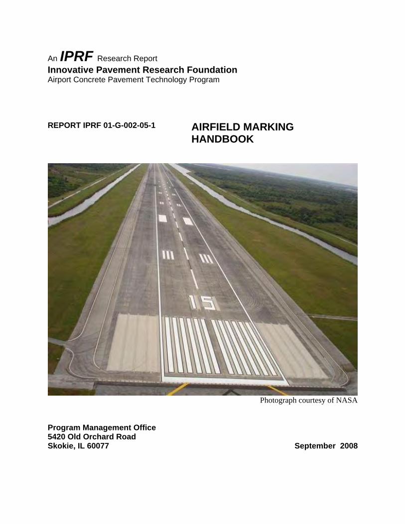
LIST OF TABLES Table Page ABBREVIATIONS ...................................................................................................................... xx Table 1-1. Summary of How Chapter Contents May Benefit Users ............................................. 3 Table 2-1. Chapter Contents May Benefit………………………………………………………..4 Table 2-2. Best Practices for Specifying Construction and Maintenance of Airfield Markings…4 Table 2-3. Runway Marking Elements .......................................................................................... 6 Table 3-1. Chapter Contents May Benefit……………………………………………………....12 Table 3-2. Best Practices for Materials........................................................................................ 12 Table 3-3. Material Compatibility Index ..................................................................................... 22 Table 4-1. Chapter Contents May Benefit………………………………………………………25 Table 4-2. Best Practices for Surface Preparation ....................................................................... 25 Table 4-3. Waterblasting Equipment ........................................................................................... 36 Table 5-1. Chapter Contents May Benefit………………………………………………………41 Table 5-2. Best Practices for Paint Removal ............................................................................... 41 Table 5-3. Paint Removal Versus Surface Preparation................................................................ 42 Table 5-4. Types and Degrees of Marking Removal................................................................... 42 Table 5-5. Recommended Marking Removal Equipment on Different Types of Pavement under
Varied Conditions ................................................................................................................. 47 Table 5-6. Waterblasting Equipment Descriptions for Paint Removal........................................ 51 Table 6-1. Chapter Contents May Benefit………………………………………………………62 Table 6-2. Best Practices for Application Procedures ................................................................. 62 Table 7-1. Chapter Contents May Benefit………………………………………………………96 Table 7-2. Best Practices for Inspection………………………………………………………... 96

Airfield Marking Handbook September 2008 xx
ABBREVIATIONS AC Advisory Circular ACC Asphaltic Cement Concrete ASTM American Society of Testing and Materials DOD Department of Defense EPA Environmental Protection Agency FAA Federal Aviation Administration FHWA Federal Highway Administration FOD Foreign Object Debris FOG Foreign Object Generator ICAO International Civil Aviation Organization IOR Index of Refraction OSHA Occupational Health and Safety Administration PCC Portland Cement Concrete PFC Porous Friction Course QCP Quality Control Plan USA United States Army USAF United States Air Force USMC United States Marine Corps USN United States Navy UV Ultraviolet VOC Volatile Organic Compounds

Airfield Marking Handbook September 2008 xxi
EXECUTIVE SUMMARY The focus on runway safety incorporates many initiatives to reduce runway incursions. Among such initiatives, airfield markings are being enhanced to increase visibility for those who need them: the pilots and others who operate on airfield surfaces. “Reducing the risk of runway incursions is one of the FAA's top priorities, as runway mishaps can prove catastrophic.”1 Although new marking schemes are intended to increase situational awareness for pilots and others operating on airfield surfaces, unless those markings are installed correctly, the efforts may not help. Airfield markings for runways, taxiways, and apron areas can be expected to provide excellent performance for several years under a range of operational and site conditions. The practice of remarking the pavements once, twice, or more often each year can be revised to maintain as necessary, based upon criteria discussed herein. When best practices are employed initially and during each maintenance cycle, airports can reduce both the frequency of remarking and the life cycle costs of the markings, and enhance safety. Airfield markings are a small component of a large construction project; often they are incidental to the overall job. And as a maintenance item on an airport manager’s to-do list, markings are often either over or under maintained. A common misconception about the marking process is that it is easy and little can go wrong. As with anything worth doing, for markings, details must be monitored, procedures must be followed, results must be inspected, and most important, specifications must be enforced. When the process is done well, the markings can perform effectively for up to five years or more. When the process is done poorly, the markings can fail within weeks or months. So although markings may be an incidental item in a large airfield project, they can pose as a significant problem when performance is shortened and safety is compromised. The added cost to the airport’s budget to maintain the markings more often than necessary could be redistributed to other, more pressing needs. The information presented here is a compendium of practices that, when used, result in longer-performing pavement markings. Good markings are the result of quality materials installed by appropriate equipment that comply with basic application requirements. The quality of newly installed airfield markings is a direct reflection of both quality workmanship and materials.
There are cost implications related to employing the best practices of marking application, because qualified personnel and appropriate equipment may not be readily available. Airport owners, design engineers, and contractors must work together to achieve the proper balance between project cost and expected performance.
1 Nicole Nelson. Enhancing Runway Safety. in Centerlines Magazine, Airports Council International - North America), January 2008, page 32.

Airfield Marking Handbook September 2008 1
1 INTRODUCTION Since roads were put in use, efforts have been made to delineate paths for travel. The ancient Romans used recessed bricks to delineate the center of the road for the drivers of chariots. Light colored rocks were embedded in the center of roads in Mexico. In the early 1900s, Edward Hines, a Michigan road commissioner, used the first road striping in the United States. In the late 1930s the idea of using glass beads became widely known when the Canadian Engineer published “Luminous Markings for Highways.” Its author stated that the “good visibility obtained and also the high abrasion resistance of the final product, made use of glass spheres advantageous.” Then during World War II, the use of beaded lines on airfields helped permit planes to land during imposed blackouts. Afterward, the use of glass beads to provide nighttime delineation became widespread. In the late 1990s many state transportation departments initiated performance programs to improve pavement markings for motorists. Some airports have adopted highway standards, but most lag behind the improved performance levels utilized in highway applications. Airport pavements are different than highway pavements, although both are composed of the same raw materials. Airport markings include the same type of materials as highway markings, but they are susceptible to different wear, weathering, exposure, stresses, and traffic.
Airfield marking maintenance, although recognized as an item on the manager’s to-do list, often is met with the attitude that it is just painting the pavement. The truth is that it is not difficult to apply markings, but it can be difficult to apply them well. There are good methods and bad methods for applying airfield markings. 1.1 PURPOSE OF THIS HANDBOOK Airport environments do present challenges for markings. Some of the challenges are similar among airports; others are specific to the environment. The advantages and disadvantages of various application processes (noting environmental conditions, pavement surfaces, and material types) are the bases for this report. Given the element of safety that good airfield markings provide, the major objective is to define the best practices. These practices will indicate the following: 1. The procedures that work and those that do not work.
2. The materials that are effective.
3. The comparison of a good marking versus a poor one. Markings on airfield pavements can be applied efficiently and effectively so that they function as a safety enhancement for those operating on airfield pavements.

Airfield Marking Handbook September 2008 2
1.2 SCOPE OF THIS HANDBOOK This handbook presents practices that when used will produce quality airfield markings. Specifically, this handbook includes the following: 1. Discussion of standard specifications set forth by the Federal Aviation Administration
(FAA) and Department of Defense (DOD) (US Air Force, US Navy, US Army, US Marine Corps and US Coast Guard).
2. Documentation of construction techniques and practices that result in quality products,
(i.e., longer lasting airfield markings). 3. Discussion of advantages and disadvantages of techniques or practices when more than
one method is available. 4. Identification of practices that result in early aging, premature failures, and poor long-
term performance of airfield markings. 5. Commonly encountered problems in meeting project specifications. 1.3 DISCLAIMER This handbook is not a construction specification guide; it does not provide detailed instructions on conducting specific airfield marking activities. It does not constitute a standard, specification, or regulation. This handbook should not be used in lieu of a project specification. The specific requirements of plans and specifications for a project take precedence. 1.4 QUALITY IN CONSTRUCTION AND MAINTENANCE PROJECTS A fundamental assumption is that quality airfield markings perform well. To attain quality markings, it is imperative for all involved (from manager to crewmember to inspector) to pay specific attention to surface preparation, quality materials, application, and inspection. Good materials and good application practices are required to obtain quality, long-lasting airfield markings. Markings installed well will require less maintenance and have an extended life cycle. Construction and maintenance requirements and specifications must be well defined. Thus, it is important that each project is designed specifically for the needs of the airport and that the specifications be tailored to each project. 1.5 SUMMARY OF HANDBOOK ORGANIZATION This handbook is organized into seven chapters, as described below. Each chapter addresses a major aspect towards attaining airfield marking quality, and can be read independently of the others. • Chapter 1-Introduction: This chapter introduces the handbook and its organization.

Airfield Marking Handbook September 2008 3
• Chapter 2–Specifications for Construction and Maintenance Activities: This chapter
addresses the specifications of markings, the construction/installation of markings, and the maintenance of markings. Key elements in the chapter include selecting proper specifications, evaluating existing conditions appropriately, and defining the scope of work based on the existing conditions.
• Chapter 3–Materials: This chapter identifies various materials that are used in airfield
markings, including both binder and beads. It provides guidelines for the proper selection of materials under specific circumstances. Selecting the correct materials for a given airfield is important in establishing good marking performance.
• Chapter 4-Surface Preparation: This chapter describes the processes that can be used to
prepare a surface for the application of airfield markings. Surface preparation includes either cleaning or removing anything that would reduce the bond between a newly applied material and the surface. Surface preparation is necessary any time markings are applied.
• Chapter 5–Pavement Marking Removal: This chapter identifies various practices that can
be used to remove airfield markings from the pavement surface. Many factors determine which removal method is the best for a specific set of conditions. The proper removal method helps to minimize pavement scarring; removing the appropriate amount of marking can optimize the life of the new marking application and minimize confusion.
• Chapter 6–Application Procedures: This chapter describes the processes used to apply
markings to an airfield pavement surface. Many factors that can have an impact on the quality of the installation and the performance of the marking are reviewed.
• Chapter 7-Inspection: This chapter describes ways to inspect various aspects of airfield
marking application. Throughout the handbook, best practices are identified by bold text (a best practice) within a chapter, and these are summarized in a table at the beginning of each chapter. The airports that adopt these practices will not only improve their marking program by providing longer-lasting, more-effective airfield markings, they will also save valuable maintenance funds. Tables at the beginning of each chapter identify who will benefit from that specific chapter. Table 1-1 summarizes the tables from all chapters.
TABLE 1-1. SUMMARY OF HOW CHAPTER CONTENTS MAY BENEFIT USERS

Airfield Marking Handbook September 2008 4
TABLE 2-1. CHAPTER CONTENTS MAY BENEFIT:
2 DESIGN AND SPECIFICATION DEVELOPMENT FOR CONSTRUCTION AND MAINTENANCE ACTIVITIES Many factors should be considered in the design and development of specifications for airfield markings, either as part of a larger construction project or for marking maintenance. Guidance literature for the prevailing jurisdiction (i.e., FAA, DOD, ICAO) are guides and they should not be copied and pasted into project specifications without due consideration of the specific conditions that exist at a particular airfield. The section that contains specifications pertaining to airfield markings should be based on the needs of a specific project, which is a best practice. For both new construction and for maintenance of existing markings, the engineer or other official should consider many different factors when evaluating, planning, and enforcing the project. There are three aspects of marking projects: (1) designing and developing specifications, (2) planning activities, and (3) developing project plans. The factors described in this chapter take place well in advance of the installation of the markings. Table 2-1 indicates the users who will benefit the most from the material in this chapter. Where used, the term best practice is highlighted in bold. Table 2-2 summarizes the best practices presented in this chapter.
When designing a project that either (a) includes airfield markings as part of the overall project or (b) is for the maintenance of airfield markings, the engineer must consider certain aspects of the work. Thus, the design of an airfield marking project, like other construction activities, includes: 1. Identify owner/user, (i.e., FAA jurisdiction or a branch of the DOD).
TABLE 2-2. BEST PRACTICES FOR SPECIFYING CONSTRUCTION AND MAINTENANCE OF AIRFIELD MARKINGS

Airfield Marking Handbook September 2008 5
2. Describe the project objectives.
3. Define the scope of work.
4. Specify methods, equipment, and materials in accordance with standards and per the needs of the airport.
5. Develop plans or blueprints.
2.1 STANDARD SPECIFICATIONS
Specifications for the application of airfield markings are maintained by different agencies. Additionally, some agencies support specifications for paint removal, rubber removal, and other related activities often associated with airfield markings. 2.1.1 Domestic Construction Specifications Most domestic airport marking work in the United States is performed in accordance with the provisions of FAA Advisory Circular 150/5340-1: Standards for Airfield Markings. This advisory circular describes the different marking elements, their placement, color, and conspicuity (visibility). Advisory Circular, AC 150/5370-10, Standards for Specifying Construction of Airports, Item P-620, describes methods for the preparation of existing surfaces, and the installation of the markings. This handbook presents the methods to employ to meet the requirements of project specifications. 2.1.2 Military Construction Specifications Each DOD agency maintains its own specification for the design and installation of airfield markings. Efforts to adopt a single standard for all military installations to provide a uniform, standard marking system, (both in design and installation) are ongoing. However, each agency maintains separate specifications.

Airfield Marking Handbook September 2008 6
2.2 AIRFIELD MARKING ELEMENTS A marking “element” is defined as a specific marking with a prescribed location, dimension, and purpose, including those on runways, taxiways, and aprons. Contained in each agency’s guidance literature are descriptions of each element, its location on the airfield surface, the dimensions of the marking, its color, and other characteristics. Table 2-3 describes the markings required for visual, non-precision, and precision runways. Appendix C contains descriptions and pictures of most of the elements for both runways and taxiways. However, the following are key points to remember:
TABLE 2-3. RUNWAY MARKING ELEMENTS
Precision, non-precision and visual (basic) runway markings are associated with approach visibility requirements and navigational aid accuracy for a particular runway end. 2.3 DESIGN ACTIVITIES Various phases associated with all construction or maintenance projects apply to an airfield marking project, whether the marking portion is (a) new construction, where the markings are considered an “incidental” part or (b) the maintenance of existing markings. 2.3.1 Pre-Bid Meeting Pre-bid meetings, although not mandatory, can benefit all stakeholders. They provide a forum where questions can be asked about expected methods, schedules, and other aspects of the project. Pre-bid meetings are a best practice. 2.3.2 Pre-Construction Conference

Airfield Marking Handbook September 2008 7
A pre-construction conference is often the first occasion for the owner/designer to meet with the contractor, and it is often the first time any subcontractors see the project. Here, all stakeholders discuss project expectations and precautions. All submittal documentation has been or is submitted at the time of this meeting. 2.3.3 Material Selection, Certification, and Testing Materials usually must be certified and/or tested before work can begin. If material certificates are an acceptable means of approval, they should be available when material is delivered to the job site, or earlier if they were delivered to another facility. When the material arrives, the inspector should verify that the documentation matches the unopened containers, and the quantity of material delivered: these are best practices. 2.3.4 Quality Control Plan (QCP) Each airport is unique, and each marking project is different from others. Accordingly, a quality control plan should be planned to parallel the different stages of work: surface preparation, layout (if necessary), and proper application rates of materials to the areas that will be marked. If markings will be removed, the expectations for the final product should be defined in the QCP. The inspector should observe test strips to establish criteria for acceptance of the work to be performed. However, a test strip is only a “snapshot” of the finished work, and it should not be regarded as a measure of what will be done throughout the job. The quality control measures discussed in the sections to follow should be employed by the quality assurance person, whether the inspector or the applicator. 2.3.5 Safety Plan A safety plan should be developed to address the requirements of 14 CFR Part 139, FAA AC 150/5370-2, Operational Safety on Airports during Construction, OSHA, EPA, local, and state regulations. 2.4 INSTALLATION OF NEW MARKINGS OR MAINTENANCE OF EXISTING
MARKINGS Airport engineers design projects that involve pavements, lighting, signage, markings, and many other aspects of airport construction. When designing a project that includes the application of airfield markings, one of two types will be involved. • Installation of new markings as all or part of a new construction project.
• Maintenance of existing markings and/or changes to existing markings.

Airfield Marking Handbook September 2008 8
2.4.1 Designing a Construction Project Involving New Airfield Markings • Describe the overall project.
• Describe the type of pavement being constructed, (i.e, bituminous asphaltic concrete or portland cement concrete), or describe the surface condition.
• Identify requirements for any changes to existing markings.
• Identify the need for any paint removal.
• Schedule phasing of markings for a time of year when weather is conducive to application of marking materials.
2.4.2 Designing a Project for the Maintenance of Existing Markings Airfield markings deteriorate over time from traffic wear, ultraviolet light, wind, rain, snowplowing, and sweeping, etc. The Development of Methods for Determining Airport Pavement Marking Effectiveness2 was part of an effort to provide quantitative criteria for inspectors and airport operators to objectively determine the need for maintenance of airfield markings. Excerpts from this study are contained in Appendix D. Certain criteria should be evaluated to determine when markings require maintenance because they do not necessarily need to be remarked each year. Some of those criteria are: 1. Faded colors or appearance.
2. Poor nighttime visibility or retro-reflectivity. 3. Existing markings are worn 50 percent
or more. 4. Existing markings are covered with
contaminants. 2.4.2.1 Evaluation of Existing Markings Take photographs to document what is observed to establish conditions “before” work begins, and include the photographs in the project specifications to better inform contractors. As a best practice, evaluate existing markings for the following conditions: 2 Development of Methods for Determining Airport Pavement Marking Effectiveness, Holly M. Cyrus, Report DOT/FAA/AR-TN03/22, Federal Aviation Administration, William J. Hughes Technical Center, Atlantic City, NJ., March 2003.
FIGURE 2-1. PEELING PAINT LAYERS

Airfield Marking Handbook September 2008 9
a. Layers of paint from older markings, figure 2-1. b. Rust discoloration. c. Algae growth.
d. UV-damage.
e. The position and dimension of existing markings.
Existing markings should be measured to verify compliance with the appropriate element. The designation marking shown in figure 2-2 should measure 5-feet wide on the “stroke,” but due to repeated remarking, it measures 6-feet, 4-inches, seen in figure 2-3. Because the dimension tolerance is 1-inch on a marking over 36-inches wide, this marking is out of tolerance per FAA AC 150/5370-10.
f. Evaluate the alignment of existing markings
for compliance with standards.
FIGURE 2-2. MEASURE EXISTING MARKINGS TO DETERMINE
COMPLIANCE WITH AC 150-5340-1.
FIGURE 2-3. MARKING DIMENSION IS OUT OF TOLERANCE.
FIGURE 2-4. MARKING IS OUT OF ALIGNMENT

Airfield Marking Handbook September 2008 10
FIGURE 2-6. RESULTS OF WATERBLASTING REMOVAL ON
POOR ASPHALT SEEN IN FIGURE 2-5.
FIGURE 2-5. A PRE-EXISTING CONDITION OF POOR ASPHALT PAVEMENT.
All specifications state that markings shall not deviate from a straight line more than ½ -inch in 50 feet. If the markings are being repainted, the applicators should perform layout (see figure 2-4) and possibly remove the marking prior to repainting. Quantify the amount of layout and/or removal to be done to comply with alignment standards: a best practice.
g. Material compatibility.
Determine the composition of existing material/coatings and verify compatibility with specified materials. Information can be found in documentation from previous marking projects. Otherwise, a lab analysis of the existing coating may be necessary to characterize it.
2.4.2.2 Evaluate Pavement Conditions Under the Existing Markings When planning for maintenance of airfield markings, it is a best practice to evaluate the condition of the pavement, whether asphalt, concrete, seal coat, rejuvenated asphalt, patched pavement, crack-sealed pavement, or other material. The integrity of pavement surfaces will affect the longevity of the new airfield markings, and this should dictate appropriate methods of surface preparation, paint removal, and/or types of material to be applied. Aged, cracked asphalt, for example, may not withstand certain methods of preparation or removal of markings, and in such cases a combination of methods may be appropriate.
Even though pavement adjacent to the markings can be in good condition, pavement under the markings is often cracked, as seen in figure 2-5. If this condition is observed, the deteriorated pavement is considered a pre-existing condition. Figure 2-6 shows scarring that can be expected after waterblasting when the existing markings are cracked. The condition of the pavement under existing markings is a gauge of how well a new marking application will last.

Airfield Marking Handbook September 2008 11
2.4.2.3 Define the Scope of Work By focusing on the conditions described previously, the designer can better define the work that needs to be done, thus minimizing confusion, surprises, and claims: a best practice. a. Quantify surface preparation and prescribe the method: a best practice. All
specifications contain wording about “surface preparation.” Methods such as sweeping, blowing with compressed air, or rinsing with water are prescribed. Airfield markings involve large areas of material that are exposed to sunlight, rain, snowplows, chemicals, etc. Some of the markings that are out of the traffic flow receive little wear. Evaluate the condition of existing markings and specify which markings need what type of surface preparation. Sweeping and blowing with compressed air should be used after a prescribed method of surface preparation. This will provide the airport with a good product, the installer with clear expectations, and the inspector with enforceable criteria.
b. Quantify amount of any paint removal, degrees, and method(s) to be used – a best practice. Obsolete markings should be completely removed. From a safety standpoint, blacked-out markings can be misleading, particularly on a wet surface at night. From maintenance standpoint, as the black paint wears off, the old marking reappears, resulting in more maintenance for the same marking. Accurately (a) quantify and describe the markings that need to be removed, (b) describe the condition of the pavement under the marking, and (c) provide any other details that will help the contractor determine the difficulty of the paint removal.
c. Select appropriate materials relative to airport pavements, pre-existing conditions, and environment. A list of approved materials is found in the guidance literature for each agency, and each one has benefits and limitations. Specifying the right material based on the needs of the airport is a best practice.
d. Specify that materials arrive on the job in sealed, unopened containers to verify initial
quantities planned for the project. This is a best practice. If the beginning inventory is known, both the contractor and inspector can verify material usage and coverage rates achieved during the course of the work.

Airfield Marking Handbook September 2008 12
TABLE 3-1. CHAPTER CONTENTS MAY BENEFIT:
3 MATERIALS Many different marking materials are used for airfield markings. At the simplest level, airfield markings consist of a combination of a binder and glass beads. Selecting the right materials for the job is important. The airport environment, amount of traffic, safety issues, schedules of operations, types of pavement, and existing marking materials should be considered when determining which materials to use. Choosing the optimal materials may increase initial costs, but over the long term this should be more cost effective; and, it can provide an added measure of safety. Chapter 3 addresses the material used for airfield markings. This includes different types of both binders and glass beads. This chapter also provides information about the performance and compatibility of various material combinations. Table 3-1 indicates the users who can gain the greatest benefit from the content of this chapter, and table 3-2 summarizes the best practices presented in this chapter.
TABLE 3-2. BEST PRACTICES FOR MATERIALS
Materials refer to the types of binders and glass beads selected for the project. Choices of binders include water-borne (Type I, II, or III), solvent-borne, epoxy, and methyl methacrylate. Choices of glass beads include TT-B-1325, Type I, III or IV. 3.1 MATERIALS COMMONLY USED Water-borne paint (TT-P-1952, Type I, II, or III) and glass beads (TT-B-1325, Type I, III or IV) are used in 95 percent of airports, both DOD and domestic. A description of other approved materials is presented in Section 3.2.

Airfield Marking Handbook September 2008 13
3.1.1 Water-Borne Paint, TT-P-1952, Type I, II or III The majority of airports in the United States use water-borne paint conforming to Federal Specification TT-P-1952. Water-borne traffic paint is the coating of choice for airports, because it has good environmental characteristics, has a fast dry time, is easy to clean up and does not generate hazardous waste. 3.1.1.1 Historical Perspective of Pavement Marking Paints Pavement marking paints typically have been categorized into two types: solvent-borne and water-borne. Before the 1980s, solvent-borne paints were the most frequently used coatings. Currently in the United States, the use of water-borne paint far exceeds the use of solvent-borne paints. The initial driver for this conversion was the passage of environmental air quality regulations limiting the Volatile Organic Compounds (VOC) content in traffic markings. Typically solvent-borne paints were not in compliance with these new, low VOC limits. As the conversion from solvent to water-borne continued, more retro-reflectivity retention data was collected, and water-borne paints became the preferred choice. Continual improvements in the chemistry of the acrylic polymer used as the “glue” in the water-borne paint only added to this preference. As paint technology continued to advance, water-borne pavement markings have been modified to fill the needs of the users while retaining their environmentally friendly status; high build paints, and other durable paints provide new levels of performance, some of which can be applied at temperatures as low as 35 F. 3.1.1.2 Benefits and Limitations of Water-Borne Paints: • Benefits of using water-borne paints include ease of use and clean up. Water is sufficient
for all clean up, and no toxic chemicals are needed. Because the material is non-hazardous, it is safe to handle the material, and empty containers can be crushed and disposed of at a landfill. Fast-dry water-borne paints can be installed quickly and new markings can be driven over soon after installation.
• Limitations of using water-borne paints are weather related. TT-P-1952, Type I dries
slowly when the humidity is high; it may take up to 30 to 45 minutes to dry. Type II is a faster drying material, and under humid conditions, drying can take up to 20-30 minutes. Type III, a high-build acrylic and a more durable product, is comparable to the Type II formulation; it contains special fast-dry polymer binders that hasten the drying process.
The “glue” in water-borne paints is the dispersion of tiny (~0.2 micron) polymer particles that cure by physical rather than chemical processes. Initially, water-borne paints achieve a no-track condition after some of the water is evaporated from the applied marking. At the no-track stage, the marking is dry to the touch and resists tracking onto the pavement surface by vehicle tires. However, at this point, the markings are soft and will not withstand wear or rain. After more

Airfield Marking Handbook September 2008 14
water has evaporated, the water-borne paints become dry through. At this point, the marking will withstand light wear and rain. After all the water evaporates, the water-borne paint continues to cure and harden (by coalescence of the polymer binder particles) to achieve full-wear resistance. Because water-borne paint cures through a combination of evaporation and coalescence, the curing time for paints depends on the following: • Paint temperature–the higher the temperature, the faster the paint will cure.
• Pavement temperature–the higher the temperature, the faster the paint will cure.
• Humidity–the more humidity, the slower the paint will cure.
• Wind speed–the higher the wind speed, the faster the paint will cure.
• Paint thickness–the thicker the paint, the slower it will cure. 3.1.2 Glass Beads The ability to see a pavement marking at night is based on the retro-reflective characteristics of the marking. “Retro-reflectivity” is the technical term that defines how much light is reflected from a light source back to a specific measurement or vantage point. The retro-reflective characteristics of a marking are associated with the glass beads applied to the marking material, the manner in which the beads are applied, and the characteristics of the marking binder. Glass beads are round spheres of either recycled or virgin glass that provide retro-reflective properties when embedded into pavement markings. Embedment is the partial submersion of the glass bead in the marking material (binder). As the binder is applied to the pavement, the glass beads (about the size of a grain of sand) are dropped onto the binder. Ideally, they become submerged part way into the binder and are suspended as the binder dries (cures) around them. If the beads are over-embedded or under-embedded, the marking becomes less retro-reflective. But when the beads are embedded properly, the marking provides visual guidance during darkness or other low visibility conditions, thus making the pavement marking functional 24 hours a day. The amount of light retro-reflected to the source is typically greatest along the illumination axis (the line from the light source to the marking). As the observer moves away from the light source, the amount of retro-reflected light decreases. Pavement marking retro-reflectivity is normally measured in units of millicandelas per meter squared per lux (mcd/m²/lux) using a standard 30 meter measurement geometry.3
3 1 candela equals 1 lumen/steradian; 1000 millicandelas equals 1 candela. Lumens are units of Luminous Flux and they measure how much light actually falls on a surface. The Luminous Flux (lumens) from a light source is equal to the Luminous Intensity (candelas) multiplied by the solid angle over which the light is emitted, taking into account the varying intensities in different directions. Source: http://www.superbrightleds.com/led_info.htm

Airfield Marking Handbook September 2008 15
The 30 meter measurement geometry established a standard arrangement for the light source, the marking, and the observer when measuring retro-reflectivity of the marking. It is based on the typical dimensions of a small European passenger car located 30 meters (98.4 ft) from a marking. For the 30 meter geometry, the entrance angle is 88.76° and the observation angle is 1.05°. Figure 3-1 illustrates the 30 meter geometry. Figure 3-2 illustrates how glass beads retro-reflect a light beam from a source, generally a headlight on a vehicle or aircraft, back to the source. The light beam bends when it enters and leaves the bead due to the difference in the index of refraction (IOR), also called the refractive index (RI), between the bead and the air outside the bead. The higher the IOR, the more efficient a bead is at retro-reflecting light.
Three types of glass beads are approved by the FAA: TT-B-1325; Type I, Type III and IV. Type I and IV have the same IOR and both are made from recycled glass (or the direct melt process). Type III glass beads are made from virgin materials and have a higher IOR.
FIGURE 3-1. 30-METER GEOMETRY
FIGURE 3-2. ILLUSTRATION OF INCIDENT LIGHT INTO GLASS BEAD AND RETURN TO SOURCE.
Airfield Marking Handbook September 2008 16
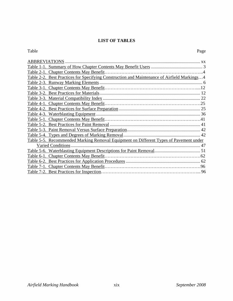
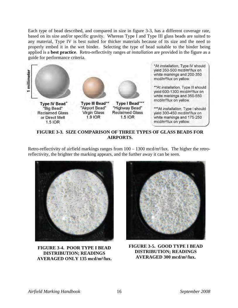
FIGURE 3-3. SIZE COMPARISON OF THREE TYPES OF GLASS BEADS FOR AIRPORTS.
Each type of bead described, and compared in size in figure 3-3, has a different coverage rate, based on its size and/or specific gravity. Whereas Type I and Type III glass beads are suited to any material, Type IV is best suited for thicker materials because of its size and the need to properly embed it in the wet binder. Selecting the type of bead suitable to the binder being applied is a best practice. Retro-reflectivity ranges at installation are provided in the figure as a guide for performance criteria.
Retro-reflectivity of airfield markings ranges from 100 – 1300 mcd/m²/lux. The higher the retro-reflectivity, the brighter the marking appears, and the further away it can be seen.
FIGURE 3-4. POOR TYPE I BEAD DISTRIBUTION; READINGS
AVERAGED ONLY 135 mcd/m²/lux.
FIGURE 3-5. GOOD TYPE I BEAD DISTRIBUTION; READINGS AVERAGED 300 mcd/m²/lux.

Airfield Marking Handbook September 2008 17
3.1.2.1 Type I Low Index Beads (1.5 IOR) The TT-B-1325, Type I low index beads have been used on highways for decades, and they were adopted by the FAA and USAF in the mid 1990s for use on airports. Made from recycled glass, Type I beads have the smallest diameter compared to the other approved beads. Type I glass beads have a coverage rate of seven pounds per gallon of water-borne or solvent-borne paint. At installation, Type I, applied properly in a white binder, should yield retro-reflectivity readings ranging from 300–450 mcd/m²/lux. Figure 3-4 shows an example of poor Type I bead distribution, and figure 3-5 demonstrates good Type I bead distribution. Excellent bead distribution should yield up to 450 mcd/m²/lux at installation. 3.1.2.2 Type II Beads Type II beads are no longer included in the specification and should not be used in airfield markings. 3.1.2.3 Type III High Index Beads (1.9 IOR) TT-B-1325, Type III high index glass beads are made from virgin materials that provide a higher IOR; this results in a concentrated beam of returned light, (see figure 3-6). In comparison, Type I or Type IV beads return a diffused light beam. When installed in white paint, Type III beads should yield reflectivity values between 600–1300 mcd/m²/lux at installation, and they represent the highest potential reflective values of any of the specified glass beads. Type III beads are recommended when long-term performance is desired. When higher retro-reflectivity readings are achieved at installation, and the beads are well anchored and embedded, the marking will remain effective for a longer period.
FIGURE 3-6. DEMONSTRATES THE GREATER RETURN OF LIGHT FROM THE 1.9 IOR (TYPE III GLASS BEADS) WHEN
COMPARED TO THE 1.5 IOR (TYPE I OR TYPE IV GLASS BEADS).

Airfield Marking Handbook September 2008 18
Type III beads are the densest of the glass beads, and require distribution of ten pounds per gallon due to their high specific gravity. Although more expensive than either Type I or Type IV, Type III beads are expected to provide 1) better initial retro-reflectivity and 2) if applied properly, better long-term performance. For example, if markings have initial readings of 800–900 mcd/m²/lux, it will take longer for the markings to lose their effectiveness, resulting in less maintenance. Conversely, if the low index beads are installed properly with initial readings of 300–500 mcd/m²/lux, reflectivity will drop below acceptable levels more quickly, thus requiring more frequent maintenance, more paint build up, etc. Figure 3-7 shows poor distribution, figure 3-8 shows excellent distribution. Studies conducted by FHWA and other agencies have concluded that, “minimum retro-reflectivity values are speed dependent. Preview or visibility distance is the distance that the delineation provides the driver to see changes in roadway alignment. Preview distance is important, especially at higher speeds [that occur during landings and take-offs of aircraft]. When drivers [or pilots] are provided with higher reflectivity values, longer preview distances are achieved, which is desirable from an information acquisition, information processing, and safety point of view”. 4 3.1.2.4 Type IV Low Index Beads (1.5 IOR), Type A and B TT-B-1325, Type IV “big beads” were approved for use by the airport industry in 2005. Also made from recycled glass or by direct melt, they are larger than any of the specified glass beads. When applied in standard white water-borne paint, the reflectivity readings should range between 350–500 mcd/m²/lux at installation.
4 Transportation Research Board, NCHRP Synthesis 306, Long-Term Pavement Marking Practices, 2002, Project 20-5, Chapter 3, Driver Needs, Retroreflectivity Requirements, and Information Through Word and Symbol Markings, page 14. ,James Migletz and Jerry Graham, consultants.
FIGURE 3-7. POOR BEAD DISTRIBUTION OF TYPE III BEADS.
FIGURE 3-8. EXCELLENT BEAD DISTRIBUTION OF TYPE III BEADS.

Airfield Marking Handbook September 2008 19
FIGURE 3-9. NON-FUNCTIONAL MARKING
DUE TO POOR REFLECTIVTY.
FIGURE 3-10. TYPE IV BEAD DISTRIBUTION IS EXCELLENT ON BOTH EDGES, BUT POOR IN THE
MIDDLE.
FIGURE 3-11. POOR TYPE IV BEAD EMBEDMENT.
However, given the size of the glass bead (0.84– 1.68 mm for Type A, and 0.59–1.19 mm for Type B), they are best suited for use in the high build acrylic binder with a specified wet film thickness of at least 25–30 mils (TT-P-1952, Type III). In contrast, TT-P-1952, Type I or II binder should only be applied between 12 and 16 mils to avoid cracking of the dry film and premature failure. When Type IV glass beads are applied to standard water-borne traffic paint at 15 mils wet film thickness, results are poor (see figures 3-9 through 3-11). Type IV glass beads are applied at the rate of eight pounds per gallon of water-borne or solvent-borne paint. After only six months of service, the markings in figure 3-9 are no longer functional at night. When the markings were applied, the coating thickness was insufficient to anchor the large glass beads, and normal traffic dislodged them.
Figure 3-10 shows what happens when glass bead guns do not uniformly cover the marking being applied. Figure 3-11 is a magnified illustration of poor embedment of beads in an insufficient coating thickness. The beads in figure 3-11 are barely anchored in the binder, and they will dislodge with very little traffic, as seen in figure 3-9. Although bead distribution was good in figures 3-10 and 3-11, reflectivity readings were only 125 mcd/m²/lux on the yellow marking. The readings would increase to a range of 200-350 mcd/m²/lux for yellow markings if the beads were properly embedded in the paint.

Airfield Marking Handbook September 2008 20
3.1.2.5 Coatings or “Coupling Agents” for Glass Beads Coatings improve performance of glass beads and are recommended by the FAA in AC 150-5370-10, Section 620, Paragraph 2-3. Reflective Media: “Glass bead treatments are specifically designed to enhance the performance characteristics of the pavement markings in the binder systems approved for use on airfields.” • Adhesion coatings improve the overall durability of the painted marking by promoting
adhesion of the glass to the specified paint. • Flotation coatings aid proper embedment of the beads in the marking material. Research
has shown that beads embedded between 50 and 60 percent (figure 3-12) in the wet marking material will provide the optimal (brightest) retro-reflective values. The marking material “behind” the bead acts as a mirror. If there is too little or too much embedment, not enough light will reach the back of the bead and return to the observer. Additionally, beads that are not embedded deeply enough will dislodge from the marking, reducing the effectiveness of the marking during darkness and other low-visibility conditions, when they are needed most (figure 3-9, seen previously).
• Moisture resistance coatings repel moisture; they assist with flow properties and inhibit
clumping or agglomeration of glass beads. • Dual coatings, often recommended for water-borne paint, help promote both adhesion
and flotation of beads.
3.2 OTHER APPROVED MATERIALS Other marking materials are approved in most guidance literature. Although water-borne paints are used predominantly on domestic, private, and military airports, some circumstances warrant the use of other approved materials.
FIGURE 3-12. GLASS BEAD EMBEDMENT IN BOTH WET AND DRY PAINT FILM.

Airfield Marking Handbook September 2008 21
3.2.1 Solvent-Borne Paint (A-A2886A, Type I or II) Solvent-borne (oil-based) paint is a single-component paint containing alkyd resins, acrylic resins, chlorinated polyolefins, or chlorinated rubber. It typically contains volatile organic compounds (VOC) such as toluene, heptanes, VM&P (Varnish Makers & Painters) naphtha, and MEK (methyl ethyl ketone), all of which exceed the EPA limits for VOCs. The use of the solvent-borne paint may be warranted in cool, humid environments, because in such environments, application restrictions are not as critical as with water-borne paints. 3.2.2 Durable Marking Materials Three marking materials are commonly classified as durable, (i.e., their life expectancy is longer than that of water-borne or solvent-borne paints): epoxy, methyl methacrylate, and thermoplastic. Used predominantly on highways, durable markings are effective on airfield pavements that are subjected to constant traffic and wear. Two warnings should be heeded about using durable materials on airfield pavements: (1) they are difficult to remove if they become obsolete, and (2) if subjected to snowplows, the glass beads may shear, causing the marking to lose reflectivity and effectiveness during darkness and other low-visibility conditions. This is a difficult problem to repair because of the durability of the material and the cost to remove and/or reapply it.
3.2.2.1 Epoxy Epoxy is a durable, two-component system consisting of a pigmented resin base and a hardener. During installation, both components are mixed at a ratio of 2 parts resin to 1 part hardener, and the material is applied with specialized equipment. This material is sprayed onto the surface at approximately 1200 psi with an airless system. Airless pumps can be set to deliver the two components at the correct ratio. Epoxy striping material is classified as 100 percent solids; this means that evaporation (of solvents or water) is not used to cure the material. Thus, without this evaporation process, a typical application rate at 60 square feet per gallon yields 30 mils wet and dries to 30 mils. Epoxy striping material is cured via a chemical reaction, and it can be applied at temperatures as low as 35 F. It can be applied over other epoxy materials, but only once. After a second application, the old material must be removed. For epoxy, Type I glass beads should be applied at 14 pounds per gallon, Type IV glass beads at 15 pounds per gallon, and Type III beads at 20 pounds per gallon. 3.2.2.2 Methyl Methacrylate Methyl methacrylate is a two-component system; it is 100 percent solid material and chemically reactive, containing no volatile solvents. The components consist of a pigmented material (the
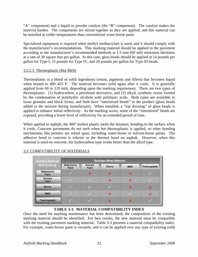
Airfield Marking Handbook September 2008 22
“A” component) and a liquid or powder catalyst (the “B” component). The catalyst makes the material harden. The components are mixed together as they are applied, and this material can be installed at colder temperatures than conventional water-borne paint. Specialized equipment is required when methyl methacrylate is used, and it should comply with the manufacturer’s recommendations. This marking material should be applied to the pavement according to the manufacturer’s recommended methods at 1.5 mm (60 mil) minimum thickness at a rate of 30 square feet per gallon. In this case, glass beads should be applied at 14 pounds per gallon for Type I, 15 pounds for Type IV, and 20 pounds per gallon for Type III beads. 3.2.2.3 Thermoplastic (Hot Melt) Thermoplastic is a blend of solid ingredients (resins, pigments and fillers) that becomes liquid when heated to 400–425 F. The material becomes solid again after it cools. It is generally applied from 60 to 120 mils, depending upon the marking requirement. There are two types of thermoplastic: (1) hydrocarbon, a petroleum derivative, and (2) alkyd, synthetic resins formed by the condensation of polyhydric alcohols with polybasic acids. Both types are available in loose granular and block forms, and both have “intermixed beads” in the product (glass beads added to the mixture during manufacture). When installed, a “top dressing” of glass beads is applied to enhance initial reflectivity. As the marking wears, some of the “intermixed” beads are exposed, providing a lower level of reflectivity for an extended period of time. When applied to asphalt, the 400º molten plastic melts the bitumen, bonding to the surface when it cools. Concrete pavements do not melt when hot thermoplastic is applied, so other bonding mechanisms like primers are relied upon, including water-borne or solvent-borne paints. The adhesive bond to concrete is inferior to the thermal bond on asphalt. However, when this material is used on concrete, the hydrocarbon type works better than the alkyd type. 3.3 COMPATIBILITY OF MATERIALS
TABLE 3-3. MATERIAL COMPATIBILITY INDEX Once the need for marking maintenance has been determined, the composition of the existing marking material should be identified. For best results, the new material must be compatible with the existing pavement marking material. Table 3-3 presents a material compatibility index. For example, water-borne paint is versatile, and it can be applied over any type of existing (old)
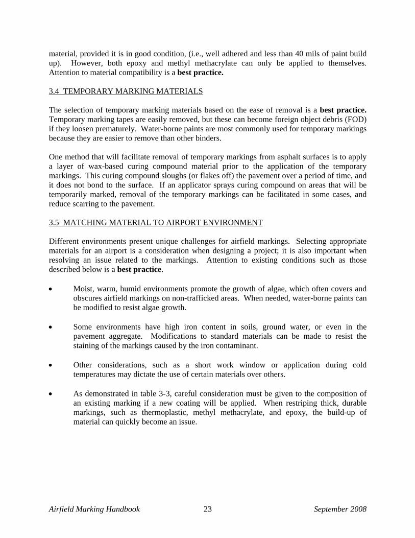
Airfield Marking Handbook September 2008 23
material, provided it is in good condition, (i.e., well adhered and less than 40 mils of paint build up). However, both epoxy and methyl methacrylate can only be applied to themselves. Attention to material compatibility is a best practice. 3.4 TEMPORARY MARKING MATERIALS The selection of temporary marking materials based on the ease of removal is a best practice. Temporary marking tapes are easily removed, but these can become foreign object debris (FOD) if they loosen prematurely. Water-borne paints are most commonly used for temporary markings because they are easier to remove than other binders. One method that will facilitate removal of temporary markings from asphalt surfaces is to apply a layer of wax-based curing compound material prior to the application of the temporary markings. This curing compound sloughs (or flakes off) the pavement over a period of time, and it does not bond to the surface. If an applicator sprays curing compound on areas that will be temporarily marked, removal of the temporary markings can be facilitated in some cases, and reduce scarring to the pavement. 3.5 MATCHING MATERIAL TO AIRPORT ENVIRONMENT Different environments present unique challenges for airfield markings. Selecting appropriate materials for an airport is a consideration when designing a project; it is also important when resolving an issue related to the markings. Attention to existing conditions such as those described below is a best practice. • Moist, warm, humid environments promote the growth of algae, which often covers and
obscures airfield markings on non-trafficked areas. When needed, water-borne paints can be modified to resist algae growth.
• Some environments have high iron content in soils, ground water, or even in the
pavement aggregate. Modifications to standard materials can be made to resist the staining of the markings caused by the iron contaminant.
• Other considerations, such as a short work window or application during cold
temperatures may dictate the use of certain materials over others. • As demonstrated in table 3-3, careful consideration must be given to the composition of
an existing marking if a new coating will be applied. When restriping thick, durable markings, such as thermoplastic, methyl methacrylate, and epoxy, the build-up of material can quickly become an issue.

Airfield Marking Handbook September 2008 24
3.6 MATERIAL TESTING Material testing is performed at the option of the Engineer (per FAA AC 150/5370-10). Manufacturers’ material certifications for each batch or lot are an accepted practice for verification of compliance. Military guidelines ETL 97-18 (USAF) and UFGS 32 01 11.51 (Navy, Army, Marines) specify that when materials are delivered to the job site, they must be sampled by the contractor in the presence of the inspector, labeled, and sent to an independent laboratory for analysis and verification of compliance. Enforcement of this specification is inconsistent, but when it is required, the testing is both time-consuming and expensive. Each material specification contains testing requirements (i.e., TT-P-1952E or TT-B-1325D). Investigation has shown that some applicators thin the paint when loading it into the machines, thus causing the material to be out of compliance when applied. Sampling the material directly from the containers does not detect this problem.

Airfield Marking Handbook September 2008 25
TABLE 4-1. CHAPTER CONTENTS MAY BENEFIT:
4 SURFACE PREPARATION To perform as expected, pavement markings must adhere to the pavement surface. Thus, the pavement surface must be prepared properly prior to applying markings. Surface preparation and paint removal are two separate procedures. Surface preparation involves the cleaning of a variety of contaminants such as curing compound, rubber, loose and flaking material/paint, algae, rust, oil, dirt, and other substances. A range of practices can be used to clean (prepare) surfaces, depending on the specific requirements of a project. Chapter 4 addresses the activities and methods associated with surface preparation prior to applying markings to airfield pavement. The types of contaminants that may need to be cleaned off and the methods that can be used to clean them are discussed. Chapter 4 addresses cleaning (preparing) markings to improve the bond between the surface and the new marking. Chapter 5 addresses removing markings when the markings are no longer applicable or for other reasons. Table 4-1 indicates the personnel who will gain the most benefit from the material in this chapter. Table 4-2 summarizes the best practices presented in this chapter.
TABLE 4-2. BEST PRACTICES FOR SURFACE PREPARATION
4.1 DEFINITION OF SURFACE PREPARATION Surface preparation is the cleaning and removal of anything that would reduce the bond between a newly applied material and the surface. All current guide specifications convey the intent to adequately prepare the surface, but the process is generally overlooked.
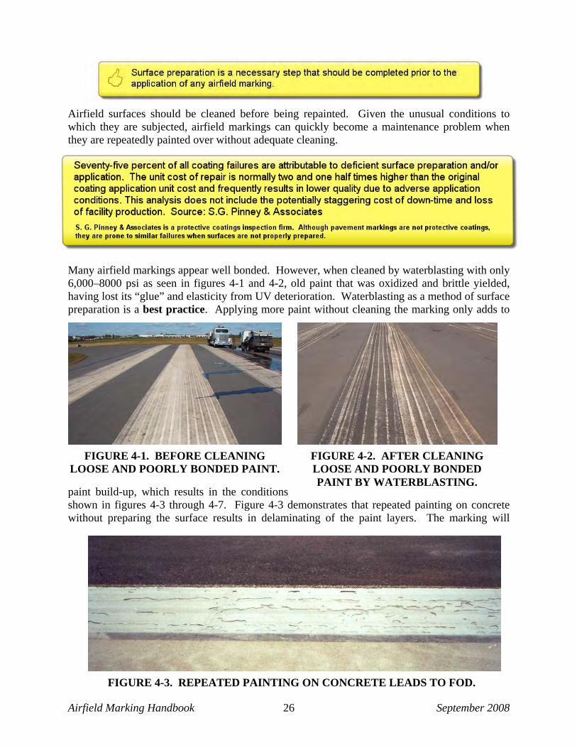
Airfield Marking Handbook September 2008 26
Airfield surfaces should be cleaned before being repainted. Given the unusual conditions to which they are subjected, airfield markings can quickly become a maintenance problem when they are repeatedly painted over without adequate cleaning.
Many airfield markings appear well bonded. However, when cleaned by waterblasting with only 6,000–8000 psi as seen in figures 4-1 and 4-2, old paint that was oxidized and brittle yielded, having lost its “glue” and elasticity from UV deterioration. Waterblasting as a method of surface preparation is a best practice. Applying more paint without cleaning the marking only adds to
paint build-up, which results in the conditions shown in figures 4-3 through 4-7. Figure 4-3 demonstrates that repeated painting on concrete without preparing the surface results in delaminating of the paint layers. The marking will
FIGURE 4-1. BEFORE CLEANING LOOSE AND POORLY BONDED PAINT.
FIGURE 4-2. AFTER CLEANING LOOSE AND POORLY BONDED PAINT BY WATERBLASTING.
FIGURE 4-3. REPEATED PAINTING ON CONCRETE LEADS TO FOD.

Airfield Marking Handbook September 2008 27
require paint removal before repainting. When asphalt is repainted without cleaning the surface, the multiple layers of paint can crack, causing premature deterioration of the asphalt, seen in figures 4-4 and 4-5. New coatings are designed to bond well to the pavement. However, if they are applied on top of old layers, and if the old layers are weak, the fresh coating will cause the old layers to crack and pull apart. The asphalt will crack as well, because the paint bonds better to the asphalt than the asphalt does to itself, evident in figure 4-5. Water penetrates into the pavement and erodes the asphalt. The freeze-thaw cycle worsens the problem, and soon the asphalt surface qualifies as a pre-existing, damaged condition.
The benefits of preparing the surface before painting it are obvious, but it takes time and money. Busy airports give applicators limited time, mostly overnight, to maintain the markings. It is not unusual for them to reapply all of the markings three or more times per year. Some of the reasons for not performing proper surface preparation include the following: 1. A lack of equipment.
2. Difficulty in coordinating surface preparation operations and marking schedules. 3. The amount of time required to prepare the surface.
4. Interruption to airport operations. Figure 4-6 shows a marking with a single coat of paint that is 30-months old, and the coating is cracked. It would benefit from cleaning prior to repainting. The life of the pavement under thick paint is much shorter than the life of an unpainted surface next to it (figure 4-7). When the markings are not cleaned before the application of more paint, the accumulating layers turn into chunks of paint, beads, and asphalt, which break apart and become FOD. The voids (missing pieces of the centerline marking) were chunks of paint, glass beads, and asphalt that dislodged and were loose on the runway.
FIGURE 4-4. REPEATED PAINTING ON ASPHALT RESULTS IN PAINT
BUILD UP, AND CRACKING OF PAINT AND PAVEMENT.
FIGURE 4-5. MAGNIFIED PHOTO OF FIGURE 4-4 SHOWS CRACKED
ASPHALT WHERE WATER INVADES.

Airfield Marking Handbook September 2008 28
The old saying goes: “If you always do what you always did, you’ll always get what you always got.” Changing practices to include surface preparation will provide longer-lasting markings, reduce build up of markings, and reduce the potential for FOD. Consistently performing surface preparation is a best practice. Whatever can be done in the time allotted should be done well. 4.2 CONTAMINANTS TO BE REMOVED The term “contaminants” is used to describe surface conditions that should be corrected before applying marking materials to the pavement. Whether on a brand new surface or over existing markings, the surface must be prepared appropriately to ensure a good bond of the new markings to the pavement. 4.2.1 Curing Compound A curing compound is sprayed on new concrete to produce a moisture-resistant membrane. The membrane generally wears off the concrete during the course of one year, depending upon traffic. If markings are to be applied, the best practice is to remove the membrane first. If paint is applied on top of the curing compound, it will flake off as the membrane sloughs off, as seen in figure 4-8. Most specifications state that all new concrete pavements shall be free of any curing compound before markings are applied. Pavement marking contractors are normally hired by a general contractor to apply markings on newly constructed pavement. Although the marking contractor’s work should include the removal of the curing compound on new concrete pavement, this is sometimes done poorly or not at all. If this happens, the markings eventually flake off.
FIGURE 4-6. THIS MARKING IS 30 MONTHS OLD AND CRACKED.
FIGURE 4-7. MANY LAYERS OF PAINT ON ASPHALT.
FIGURE 4-8. EXAMPLE OF POOR REMOVAL OF
CURING COMPOUND.
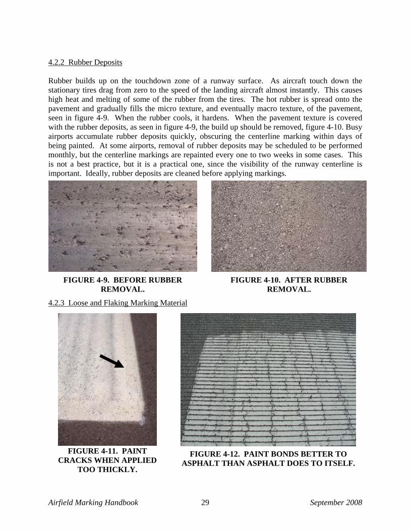
Airfield Marking Handbook September 2008 29
4.2.2 Rubber Deposits Rubber builds up on the touchdown zone of a runway surface. As aircraft touch down the stationary tires drag from zero to the speed of the landing aircraft almost instantly. This causes high heat and melting of some of the rubber from the tires. The hot rubber is spread onto the pavement and gradually fills the micro texture, and eventually macro texture, of the pavement, seen in figure 4-9. When the rubber cools, it hardens. When the pavement texture is covered with the rubber deposits, as seen in figure 4-9, the build up should be removed, figure 4-10. Busy airports accumulate rubber deposits quickly, obscuring the centerline marking within days of being painted. At some airports, removal of rubber deposits may be scheduled to be performed monthly, but the centerline markings are repainted every one to two weeks in some cases. This is not a best practice, but it is a practical one, since the visibility of the runway centerline is important. Ideally, rubber deposits are cleaned before applying markings.
4.2.3 Loose and Flaking Marking Material
FIGURE 4-9. BEFORE RUBBER REMOVAL.
FIGURE 4-10. AFTER RUBBER REMOVAL.
FIGURE 4-11. PAINT CRACKS WHEN APPLIED
TOO THICKLY.
FIGURE 4-12. PAINT BONDS BETTER TO ASPHALT THAN ASPHALT DOES TO ITSELF.

Airfield Marking Handbook September 2008 30
FIGURE 4-14. WATER FROM THE AIRPORT'S FIRE TRUCK, WITH 150
PSI, RINSED THE SIDELINE.
FIGURE 4-15. THE SAME SIDELINE AND
THRESHOLD MARKING EIGHTEEN MONTHS
LATER.
Loose, flaking and poorly bonded material from previous marking applications is the most common condition dictating surface preparation. UV deterioration, jet blast, and freeze/thaw cycles affect markings and pavements, but the markings react differently compared to the pavement. Figure 4-11 resulted when paint was applied non-uniformly, heavier in the middle of the line, lighter on the edges. The thick paint in the middle cracked. If the stressed and damaged material is not removed through preparation of the surface, repeated coatings cause asphalt pavement to deteriorate prematurely. Most markings (coatings) absorb moisture and expand/contract differently than the pavement, contributing to the cracking seen in figure 4-12. 4.2.4 Algae Algae grow in warm, humid environments, particularly on surfaces that have light traffic. Airport pavements out of the traffic path are susceptible to algae growth. Algae invade everything in their path, covering airfield markings and the pavement. When the markings become “gray” or “black” with the contaminant, they become obscured, as observed in figure 4-13. Although the markings may appear faded or gone, they are merely covered with algae. If new markings are applied over the algae-covered surface, the bond will be poor, and the algae that become sandwiched between the layers of paint will thrive when moist. There are two methods that can be used to distinguish microbial (fungal and algal) growth from dirt on airport markings: (1) Wearing gloves and eye protection, spray household bleach on a portion of the area, where the airport markings have become darkened. If this discoloration turns lighter after the bleach has been applied, there is microbial growth. If the discoloration does not change color, it is dirt. (2) Spraying water on a darkened surface may eventually result in blooming effects such as a greenish tinge. If this occurs, algae are present. Figures 4-14 and 4-15 were taken 18 months apart. The markings were washed off with water from the airport’s
FIGURE 4-13. MARKINGS ARE OBSCURED BY ALGAE.

Airfield Marking Handbook September 2008 31
FIGURE 4-20. SAME MARKINGS AS IN FIGURES 4-18 AND 4-19,
AFTER THIRTY MONTHS. FIGURE 4-19. PAINT
FORMULATED TO RESIST ALGAE.
FIGURE 4-18. PAINT USED WAS STANDARD
TT-P-1952E.
Untreated paint, algae
growing after 18 months
fire truck prior to being painted by the contractor. As an expedient and cost-conscious measure, rinsing the algae-coated markings was better than doing nothing, but within a short time, algae covered the markings again, perpetuating the cycle. On another project, the algae-covered surface was prepared with high-pressure waterblasting equipment before repainting. The “before and after” pictures in figures 4-16 and 4-17 demonstrate the value of thorough preparation. Not only was the algae washed off, so was all loose and poorly bonded paint: a best practice. On the same airport project, eighteen months after repainting most of the runway with an algae-resistant formulation, the “treated" threshold markings seen in figure 4-19 were free of algae,
whereas the untreated markings shown in figure 4-18 supported new algae growth. Figure 4-20 shows the same threshold markings 30 months after they were painted. The algae growth is beginning to cover the untreated marking (on the left in figure 4-20). Figures 4-21 and 4-22 provide close-up photographs of the treated and untreated markings in figures 4-18 and 4-19 respectively, indicating the lack of algae growth on the treated markings and the presence of algae on the untreated markings.
FIGURE 4-16. BEFORE WATERBLASTING: ALGAE
OBSCURE MARKING.
FIGURE 4-17. AFTER WATERBLASTING, BUT BEFORE
PAINTING.
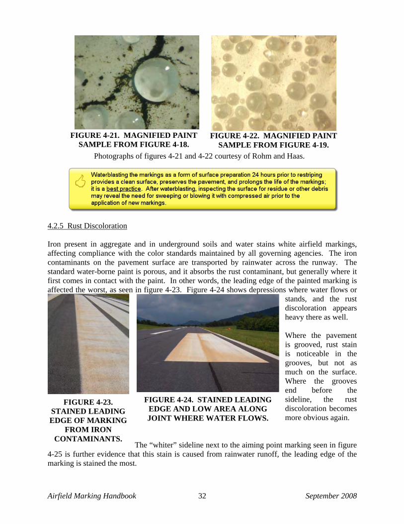
Airfield Marking Handbook September 2008 32
4.2.5 Rust Discoloration Iron present in aggregate and in underground soils and water stains white airfield markings, affecting compliance with the color standards maintained by all governing agencies. The iron contaminants on the pavement surface are transported by rainwater across the runway. The standard water-borne paint is porous, and it absorbs the rust contaminant, but generally where it first comes in contact with the paint. In other words, the leading edge of the painted marking is affected the worst, as seen in figure 4-23. Figure 4-24 shows depressions where water flows or
stands, and the rust discoloration appears heavy there as well. Where the pavement is grooved, rust stain is noticeable in the grooves, but not as much on the surface. Where the grooves end before the sideline, the rust discoloration becomes more obvious again.
The “whiter” sideline next to the aiming point marking seen in figure
4-25 is further evidence that this stain is caused from rainwater runoff, the leading edge of the marking is stained the most.
FIGURE 4-22. MAGNIFIED PAINT SAMPLE FROM FIGURE 4-19.
FIGURE 4-21. MAGNIFIED PAINT SAMPLE FROM FIGURE 4-18.
Photographs of figures 4-21 and 4-22 courtesy of Rohm and Haas.
FIGURE 4-23. STAINED LEADING EDGE OF MARKING
FROM IRON CONTAMINANTS.
FIGURE 4-24. STAINED LEADING EDGE AND LOW AREA ALONG JOINT WHERE WATER FLOWS.

Airfield Marking Handbook September 2008 33
FIGURE 4-27. EVIDENCE OF RUST CONTAMINATION
FROM SUBSTRATE.
FIGURE 4-28. THE SAME SIDELINE IN FIGURE 4-27 TWO
YEARS LATER.
FIGURE 4-26. WHITE CENTERLINE LOOKS YELLOW.
This centerline should be
white.
This centerline should be yellow.
In some instances the rust discoloration enters the markings from the bottom up, and the entire marking is discolored, as seen in figure 4-26. Figures 4-27 and 4-28 illustrate a more obvious example of contaminated ground water affecting the surface marking by seeping up through a crack in the pavement. Figure 4-28 was taken two years after figure 4-27, demonstrating the advantage of using a modified formulation of TT-P-1952 to resist the rust staining. When remarking rust-discolored markings, cleaning them to remove as much of the rust deposits as possible is a best practice. Figure 4-29 is an example of a stained marking that
was not cleaned before it was repainted. Within a few months, the stain bled through and the marking became discolored again. A commercial rust remover was tested on severely rust-discolored markings. As seen in figures 4-30 and 4-31, the chemical agent that removed the rust also damaged the glass beads, making them ineffective during darkness.
FIGURE 4-25. GROOVED SURFACE MAKES STAIN LESS NOTICEABLE.
FIGURE 4-29. REPAINTING WITHOUT CLEANING THE STAIN RESULTS IN BLEED-THROUGH.
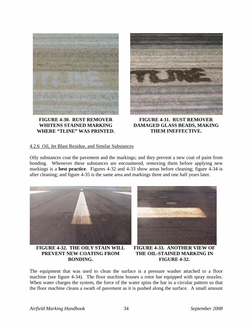
Airfield Marking Handbook September 2008 34
4.2.6 Oil, Jet Blast Residue, and Similar Substances Oily substances coat the pavement and the markings; and they prevent a new coat of paint from bonding. Whenever these substances are encountered, removing them before applying new markings is a best practice. Figures 4-32 and 4-33 show areas before cleaning; figure 4-34 is after cleaning; and figure 4-35 is the same area and markings three and one half years later.
The equipment that was used to clean the surface is a pressure washer attached to a floor machine (see figure 4-34). The floor machine houses a rotor bar equipped with spray nozzles. When water charges the system, the force of the water spins the bar in a circular pattern so that the floor machine cleans a swath of pavement as it is pushed along the surface. A small amount
FIGURE 4-30. RUST REMOVER WHITENS STAINED MARKING
WHERE “TLINE” WAS PRINTED.
FIGURE 4-31. RUST REMOVER DAMAGED GLASS BEADS, MAKING
THEM INEFFECTIVE.
FIGURE 4-32. THE OILY STAIN WILL PREVENT NEW COATING FROM
BONDING.
FIGURE 4-33. ANOTHER VIEW OFTHE OIL-STAINED MARKING IN
FIGURE 4-32.

Airfield Marking Handbook September 2008 35
of detergent added to the water helps break down the oils both on the surface and in depressions in the pavement. A vacuum attachment recovers the oily wastewater for proper disposal.
Jet blast residue is another contaminant that accumulates at thresholds and in areas where aircraft test their engines. Figure 4-36 shows the difference between pavement with jet blast residue and pavement where the residue has been cleaned by waterblasting. It is a best practice to clean off jet blast residue before applying more material to the marking.
4.2.7 Dirt and Loose Rocks Loose materials are more obvious and are generally cleaned before markings are applied. Figure 4-37 shows how a paint-removal process leaves dust that must be blown off, and then vacuumed before the new markings can be painted. The surface to be marked should be free of anything that would prevent the marking material from bonding to the surface.
FIGURE 4-34. THE PROCESS USED TO REMOVE OIL STAIN.
FIGURE 4-35. THE SAME AREA THREE AND ONE-HALF YEARS LATER.
FIGURE 4-36. TAXIWAY SHOULDER MARKING WAS CONTAMINATED WITH
OILY JET BLAST.
FIGURE 4-37. COMPRESSED AIR REMOVES FINE RESIDUE AFTER PAINT REMOVAL OPERATION.

Airfield Marking Handbook September 2008 36
4.3 EQUIPMENT Different types of equipment can be used to prepare surfaces prior to applying markings. The method of cleaning should be selected based on the conditions. In all cases, the experience and skill of the equipment operator can affect how well the surface preparation is performed. 4.3.1 Waterblasters Several kinds of waterblasting equipment are appropriate for surface preparation. Which one to select will depend on the amount and extent of cleaning needed and the time that is allotted to do the work. Table 4-3 is a matrix of the various types of waterblasting equipment. Waterblasting equipment is differentiated by the pressure attained and the volume of water used in the operation. All waterblasters, from pressure washers to ultra-high machines, use pressurized water to do the work.
TABLE 4-3. WATERBLASTING EQUIPMENT
The following sections provide a brief description of each type of waterblaster with general capabilities, but all types represent a best practice for preparing surfaces when followed by sweeping or vacuuming. 4.3.1.1 Pressure Washers A pressure washer is a type of waterblaster by definition. Good for small areas they attain pressures up to 3,500 psi. Pressure-washing systems can use floor machines (seen in figure 4-34), can add detergents to the water tank, or can be used with a hand wand. By taking enough time, pressure washers can remove most contaminants, except for rubber deposits and curing compound. 4.3.1.2 Low-Pressure Waterblasters Low-pressure waterblasters can reach pressures up to 10,000 psi and they are sometimes available at equipment-rental establishments. Good for surface preparation, this system can be truck mounted, using a straight bar with a series of tips (seen in
FIGURE 4-38. LOW-PRESSURE WATERBLASTER.

Airfield Marking Handbook September 2008 37
figure 4-38) or used with a hand wand or weighted floor machine, similar to the one seen in figure 4-34. 4.3.1.3 High-Pressure Waterblasters High-pressure waterblasters reach pressures up to 20,000 psi, and they are good for surface preparation of curing compound, rubber removal, and can remove paint from sound pavement surfaces. This system uses a high volume of water, up to 25 gpm, delivering water with hydraulic force to penetrate, lift, and clean contaminants from the surface. 4.3.1.4 Ultra High-Pressure Waterblasters Ultra high-pressure waterblasters attain pressures up to 50,000 psi, and they work well for removing contaminants on any surface. When used for surface preparation, ultra-high-pressure units can operate at half capacity (or 25,000 psi) and they move faster than they would during a paint removal operation. These systems often include an integrated vacuum system to collect the water and debris during the cleaning process. 4.3.2 Shotblasters Shotblasters propel steel shot, walnut shells, or other abrasive material onto the surface to remove paint and prepare surfaces. Grooved pavements (cut into runways to prevent hydroplaning) can present some issues for shotblasters since the shot escapes the vacuum system and some will remain on the surface where it will rust. An integrated vacuum system must be functioning properly to recover the shot to reduce the likelihood of it becoming FOD. If the surface is uneven, a magnetized bar should be used to sweep the prepared surface, picking up most of the remaining shot. 4.3.3 Grinders Grinders can be used for surface preparation. They are equipped with rotating drums that spin vertically, horizontally, or both ways. Each drum is fitted with a series of steel tips, tungsten carbide steel tips, leather tabs with steel tips, or other abrasive material that, when lowered to the ground, cuts into the coating. They scarify a pavement marking, and if this is done lightly, it can be used for surface preparation to remove loose and poorly bonded material. The surface must be flat for the grinders to strike all of the marking that will be prepared. Thorough clean up after grinding is advisable, such as rinsing the affected pavement with water or blowing with compressed air to remove any residue. The use of grinders to remove algae is not effective, because the paint would be removed in the process. The same is true of rust discoloration. However, for removing loose and poorly bonded paint, a light pass with a grinder can be effective.

Airfield Marking Handbook September 2008 38
4.3.4 Sandblasters Sandblasters have been used for many years to prepare surfaces and remove existing coatings. This method, although potentially messy because of broadcasting sand around the work area, is effective and useful. Sandblasting equipment is available for rent from most locales, and it comes equipped with the personal protective equipment that is necessary for safe operation, since the silica in the sand is a health hazard for the workers. There are substitutes for sand, such as “black beauty” or other blasting media, which does not contain silica. 4.3.5 Brooms, Vacuum Equipment/Air Compressors Brooms and vacuum sweepers are used to remove loose debris, dirt, and other material from surfaces. A best practice is to use them after other methods of surface preparation to remove the residue from those operations. Air compressors or leaf blowers (figure 4-39) also can be used to remove the loose particulate from areas that have been cleaned before they are marked. 4.4 QUALITY CONTROL Quality control is important during the surface preparation process to ensure that pavement, fixtures, and joints are not damaged. The process must effectively remove contaminants that would prevent the new coatings from bonding to the surface. 4.4.1 Well Defined Specifications Specifications that are well defined are necessary to communicate expectations to the applicator. They also provide the inspector with the criteria to enforce compliance. Include surface preparation as a separate line item; this alerts the contractor of project expectations and is a best practice. 4.4.2 Measurable Criteria Measurable criteria should be used to evaluate the effectiveness of the surface preparation. The result of cleaning the contaminants, discussed previously, can be monitored for the following specific results. 4.4.2.1 Curing Compound Removal Current specifications call for the removal of all visible curing compound material from the pavement. New concrete appears white when the curing compound is present. When it is
FIGURE 4-39. LEAF BLOWER CLEANS LOOSE RESIDUE AFTER
SURFACE PREPARATION.

Airfield Marking Handbook September 2008 39
properly removed, the concrete appears gray or tan. If there is still evidence of the “white” curing compound, have the equipment operator run another pass over the area to see if more can come up. If the white stain resists a second attempt, the membrane is unlikely to cause a problem. 4.4.2.2 Rubber Deposits Although considered a surface contaminant, rubber accepts a coating of water-borne paint well. During operations to remove rubber, seen in figure 4-40, any coatings applied on top of the rubber will be removed during the rubber-removal process. 4.4.2.3 Loose and poorly bonded materials A pull test, seen in figure 4-41, is a means of checking for loose materials, such as dirt or debris, generated by a surface preparation or paint-removal process. Using a piece of duct
tape that is pressed onto the surface, pull up to expose any remaining grit or debris that should be cleaned, swept, or blown off before applying markings. A scraper can also be used to spot check areas that have been prepared to see if any areas larger than a 1-inch square of old marking material can be pulled up (see figure 4-42). 4.4.2.4 Algae Algae can almost completely obscure the markings. Thorough brooming can remove the algae growing on the surface. However, if the paint is also peeling up,
FIGURE 4-40. HEAVY RUBBER DEPOSITS WERE REMOVED FROM
THIS CENTERLINE MARKING WITH ULTRA HIGH-PRESSURE
WATERBLASTING.
FIGURE 4-41. PULL TEST.
FIGURE 4-42. LOOSE PAINT FOUND AFTER SURFACE PREPARATION. PAINT REMOVAL IS REQUIRED.
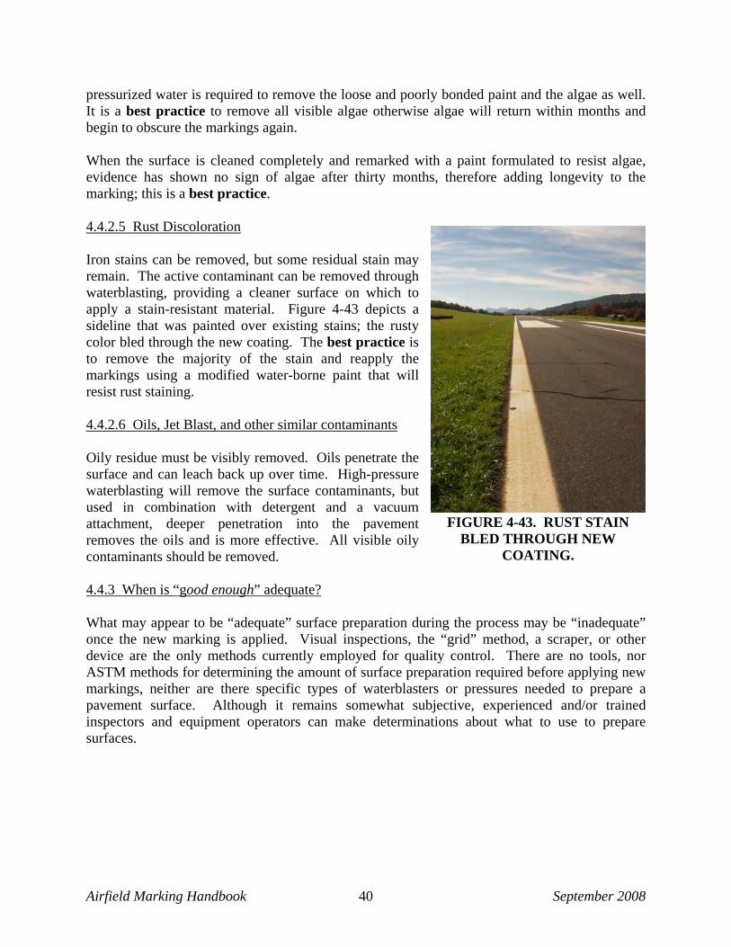
Airfield Marking Handbook September 2008 40
pressurized water is required to remove the loose and poorly bonded paint and the algae as well. It is a best practice to remove all visible algae otherwise algae will return within months and begin to obscure the markings again. When the surface is cleaned completely and remarked with a paint formulated to resist algae, evidence has shown no sign of algae after thirty months, therefore adding longevity to the marking; this is a best practice. 4.4.2.5 Rust Discoloration Iron stains can be removed, but some residual stain may remain. The active contaminant can be removed through waterblasting, providing a cleaner surface on which to apply a stain-resistant material. Figure 4-43 depicts a sideline that was painted over existing stains; the rusty color bled through the new coating. The best practice is to remove the majority of the stain and reapply the markings using a modified water-borne paint that will resist rust staining. 4.4.2.6 Oils, Jet Blast, and other similar contaminants Oily residue must be visibly removed. Oils penetrate the surface and can leach back up over time. High-pressure waterblasting will remove the surface contaminants, but used in combination with detergent and a vacuum attachment, deeper penetration into the pavement removes the oils and is more effective. All visible oily contaminants should be removed. 4.4.3 When is “good enough” adequate? What may appear to be “adequate” surface preparation during the process may be “inadequate” once the new marking is applied. Visual inspections, the “grid” method, a scraper, or other device are the only methods currently employed for quality control. There are no tools, nor ASTM methods for determining the amount of surface preparation required before applying new markings, neither are there specific types of waterblasters or pressures needed to prepare a pavement surface. Although it remains somewhat subjective, experienced and/or trained inspectors and equipment operators can make determinations about what to use to prepare surfaces.
FIGURE 4-43. RUST STAIN BLED THROUGH NEW
COATING.
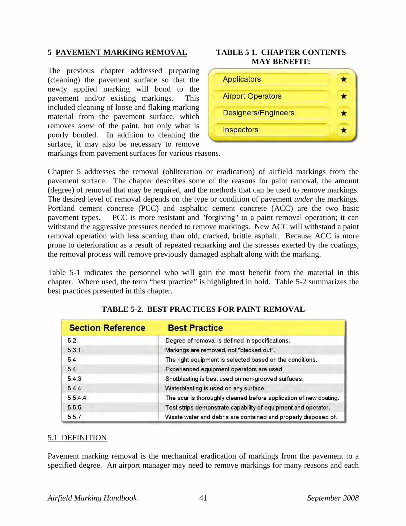
Airfield Marking Handbook September 2008 41
5 PAVEMENT MARKING REMOVAL The previous chapter addressed preparing (cleaning) the pavement surface so that the newly applied marking will bond to the pavement and/or existing markings. This included cleaning of loose and flaking marking material from the pavement surface, which removes some of the paint, but only what is poorly bonded. In addition to cleaning the surface, it may also be necessary to remove markings from pavement surfaces for various reasons. Chapter 5 addresses the removal (obliteration or eradication) of airfield markings from the pavement surface. The chapter describes some of the reasons for paint removal, the amount (degree) of removal that may be required, and the methods that can be used to remove markings. The desired level of removal depends on the type or condition of pavement under the markings. Portland cement concrete (PCC) and asphaltic cement concrete (ACC) are the two basic pavement types. PCC is more resistant and "forgiving" to a paint removal operation; it can withstand the aggressive pressures needed to remove markings. New ACC will withstand a paint removal operation with less scarring than old, cracked, brittle asphalt. Because ACC is more prone to deterioration as a result of repeated remarking and the stresses exerted by the coatings, the removal process will remove previously damaged asphalt along with the marking. Table 5-1 indicates the personnel who will gain the most benefit from the material in this chapter. Where used, the term “best practice” is highlighted in bold. Table 5-2 summarizes the best practices presented in this chapter.
TABLE 5-2. BEST PRACTICES FOR PAINT REMOVAL
5.1 DEFINITION Pavement marking removal is the mechanical eradication of markings from the pavement to a specified degree. An airport manager may need to remove markings for many reasons and each
TABLE 5 1. CHAPTER CONTENTS MAY BENEFIT:

Airfield Marking Handbook September 2008 42
reason will dictate the degree of eradication. Table 5-3 illustrates the differences between paint removal and surface preparation; it shows the benefits that can be realized through regular preparation.
TABLE 5-3. PAINT REMOVAL VERSUS SURFACE PREPARATION
5.2 DEGREES OF REMOVAL Different types of marking removal and degrees of removal can be specified. Not all of removal situations require 100 percent, 95, or even 85 percent removal of the markings. Two key factors are included in a successful removal operation: (1) specifying in the construction documents/specifications what process is expected and (2) explaining exactly where and how much of the markings will be removed. If marking removal is needed in more than one area and for more than one reason, the degree of removal should be clearly defined for each area. This information prepares the contractor, provides expectations for the owner, enables the inspector to validate results, and is a best practice. The degree of removal is dictated by the reason for conducting the paint removal. Different types are defined in Table 5-4 along with the recommended degree of paint removal.
TABLE 5-4. TYPES AND DEGREES OF MARKING REMOVAL

Airfield Marking Handbook September 2008 43
5.2.1 100 Percent Removal or Complete Eradication In 100 percent removal, all of the marking is removed. Depending upon the condition of the pavement under the marking, 100 percent removal has the potential of causing the most scarring. If the underlying pavement can sustain the forces of the removal operation and complete eradication is specified, then 100 percent removal should be achieved. If pavement damage begins to occur with one method, the process should stop and the engineer/inspector should consider other methods or combinations of methods that may achieve the desired result without causing damage to the underlying pavement. 5.2.2 90 – 95 Percent Removal After 90 to 95 percent of an existing marking is removed, a small amount of marking material will remain after the removal operation is complete. In contrast to 100 percent removal, 90–95 percent removal of markings can spare the pavement from damage. Between 90–95 percent removal is recommended when changing marking colors, and between 85–90 percent removal is appropriate to remove excessive marking build up. 5.2.3 80-85 Percent Removal Removing 80 to 85 percent of existing markings is required prior to the application of a seal coat per FAA AC 150/5370-10C, Section 626-4.4. Leaving 15 to 20 percent of an existing marking will expose enough pavement so that a seal coat or other surface treatment will bond to the underlying pavement. 5.2.4 85-100 Percent Removal When an incompatible material is applied over different and existing markings, the degree of removal depends on the new coating. For example, if epoxy markings are being applied over anything except epoxy, 100 percent of the existing marking must be removed. However, if solvent-borne paint is being applied over water-borne paint, removing 85 percent of the existing coating would be acceptable. 5.3 TYPES OF MARKING REMOVAL Different reasons exist for removing markings from pavement, including the following: 1. A new pattern or configuration will make older markings obsolete. The old markings must
be completely obliterated to prevent confusion. 2. Markings should be removed prior to overlaying asphalt or applying a seal coat. Leaving the
markings may prevent a good bond of asphalt or sealant to the painted surface. Removal of some but not all of the existing marking would ensure a better bond.
3. Similar reasons for removing markings are outlined next, and the recommended degrees of removal are given for each instance.
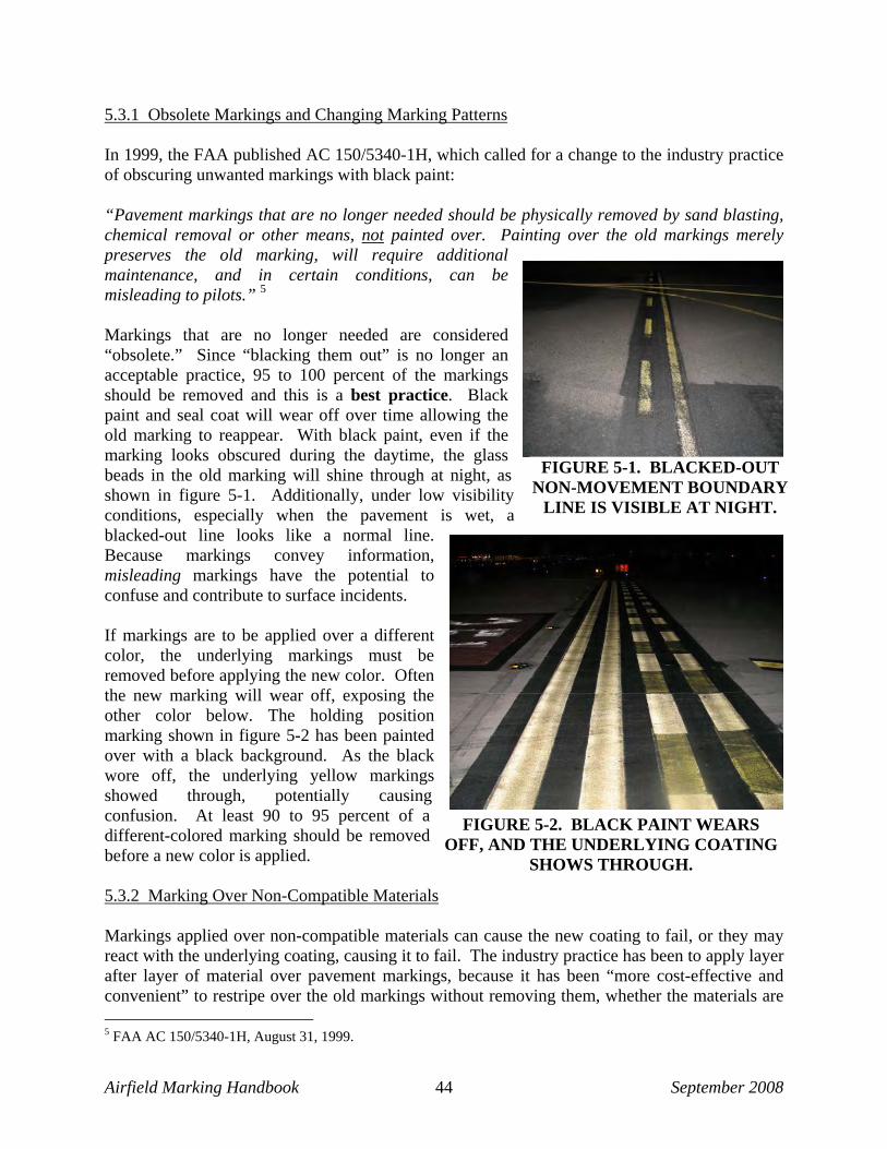
Airfield Marking Handbook September 2008 44
5.3.1 Obsolete Markings and Changing Marking Patterns In 1999, the FAA published AC 150/5340-1H, which called for a change to the industry practice of obscuring unwanted markings with black paint: “Pavement markings that are no longer needed should be physically removed by sand blasting, chemical removal or other means, not painted over. Painting over the old markings merely preserves the old marking, will require additional maintenance, and in certain conditions, can be misleading to pilots.” 5 Markings that are no longer needed are considered “obsolete.” Since “blacking them out” is no longer an acceptable practice, 95 to 100 percent of the markings should be removed and this is a best practice. Black paint and seal coat will wear off over time allowing the old marking to reappear. With black paint, even if the marking looks obscured during the daytime, the glass beads in the old marking will shine through at night, as shown in figure 5-1. Additionally, under low visibility conditions, especially when the pavement is wet, a blacked-out line looks like a normal line. Because markings convey information, misleading markings have the potential to confuse and contribute to surface incidents. If markings are to be applied over a different color, the underlying markings must be removed before applying the new color. Often the new marking will wear off, exposing the other color below. The holding position marking shown in figure 5-2 has been painted over with a black background. As the black wore off, the underlying yellow markings showed through, potentially causing confusion. At least 90 to 95 percent of a different-colored marking should be removed before a new color is applied. 5.3.2 Marking Over Non-Compatible Materials Markings applied over non-compatible materials can cause the new coating to fail, or they may react with the underlying coating, causing it to fail. The industry practice has been to apply layer after layer of material over pavement markings, because it has been “more cost-effective and convenient” to restripe over the old markings without removing them, whether the materials are 5 FAA AC 150/5340-1H, August 31, 1999.
FIGURE 5-1. BLACKED-OUT NON-MOVEMENT BOUNDARY
LINE IS VISIBLE AT NIGHT.
FIGURE 5-2. BLACK PAINT WEARS OFF, AND THE UNDERLYING COATING
SHOWS THROUGH.

Airfield Marking Handbook September 2008 45
compatible or not. Good adhesion can be obtained if like materials are applied to each other. If the existing coatings are incompatible with the specified new material, the best practice is to remove 85 to 100 percent of the old marking. 5.3.3 Remove Marking Build Up (i.e., Excessive Layers) When more than two coatings of markings have been applied to asphalt without surface preparation, the layers can start to curl, split, spall, or crack, as seen in figure 5-3. In this case, at least 85 percent of the marking should be removed before remarking to reduce reflective cracking and continued build up. Cracks become channels for water to penetrate the asphalt. The water erodes the pavement under the marking, resulting in premature deterioration. Coatings are designed to bond to a specific substrate, like asphalt, and often they bond better to the asphalt than the asphalt does to itself, as seen in figures 5-4 and 5-5.
Portland cement concrete is less susceptible to erosion from moisture through cracks in the marking. However, moisture will accumulate between the concrete surface and the initial layer of paint. Layer after layer of paint exerts tension over the marking. Once the initial layer of paint loosens from the surface, chunks start to break up, and the markings become a foreign object generator (FOG), seen in figure 5-6.
FIGURE 5-3. CRACKED AND PEELING MARKINGS – REMOVE 85 PERCENT.
FIGURE 5-6. HEAVY PAINT BUILD UP ON CONCRETE.
FIGURE 5-4. CRACKED MARKINGS WITH DETERIORATED ASPHALT
UNDERNEATH IS A PRE-EXISTING CONDITION.
FIGURE 5-5. MAGNIFICATION OF CRACKED MARKINGS AND ASPHALT
FROM FIGURE 5-4.

Airfield Marking Handbook September 2008 46
Operations for removing paint build up could be eliminated if the surface is adequately prepared before more marking materials are applied. 5.3.4 Seal Coat or Other Surface Treatment AC 150/5370-10C states, “Any painted stripes or markings on the surface of the runways or taxiways to be treated, shall be removed.” 6 This means that markings must be removed before applying a seal coat or other surface treatment. Removing 80 – 85 percent of the markings exposes pavement, providing a better surface for the sealant to bond. A seal coat is generally used to preserve and extend the life of pavement. Removing more than 80 to 85 percent of the markings may cause damage to pavement that is already in fair to poor condition. Applying a seal coat over old, scaling paint will cause the layers to pull apart, as seen in figure 5-7. 5.4 EQUIPMENT Equipment designed to remove markings is available by purchase, lease, or contract, depending upon an airport’s locale and budget. Selecting the right equipment is a best practice, and is based on many factors, including: 1. Amount (quantity) of removal.
2. Type of pavement.
3. Condition of pavement.
4. Thickness and condition of material being removed.
5. Type of material being removed. Different types of equipment are listed in table 5-5. As with surface preparation, the skill and experience of the equipment operator determines the quality of the removal product. A best practice is getting references from the paint removal equipment operator or contractor to ensure the capability of the operator.
6 AC 150/5370-10C, Section 626-4.4
FIGURE 5-7. PAINT IS PEELING OFF OF REJUVENATOR APPLIED OVER
OLD MARKINGS.

Airfield Marking Handbook September 2008 47
TABLE 5-5. RECOMMENDED MARKING REMOVAL EQUIPMENT ON DIFFERENT TYPES OF PAVEMENT UNDER VARIED CONDITIONS
Marking removal equipment is similar, if not identical, to equipment that is used for surface preparation. However, a few important differences exist: 1. A slower speed is needed to remove the marking.
2. Higher pressures are required when using water.
3. Special care must be taken to avoid damage to the underlying pavement.
Marking removal will leave a visible scar. Depending upon the integrity of the pavement under the paint, pre-existing conditions can compound damage to the pavement. All markings that will be removed must be carefully evaluated, which will indicate the method of removal, degree of the removal, and the expectations for the project.
5.4.1 Grinding/Milling/“Rotopeen” Grinding, milling, or rotopeen machines are drum units that can be hand operated or mounted on a skid steer or other motorized vehicles. Figures 5-8 and 5-9 indicate acceptable scarring from grinding on asphalt and concrete. Scarring left on asphalt from the impressions of the grinding blades fade over time. Some of the characteristics of grinding as a method of paint removal follow: • Effective on asphalt, especially if aged and cracked. Effective on concrete, although the
scars are permanent. • Scrapes and cuts the surface to remove paint.
• Can be manually operated.

Airfield Marking Handbook September 2008 48
• Is a slow process – 500 SF per hour typically, depending on thickness and type of material.
• Is not recommended for grooved surfaces.
5.4.2 Sandblasting Sandblasting combines compressed air, sand or other abrasive material which is propelled toward the surface. A relatively slow process for removing airfield markings it can be used for small areas when other equipment is difficult to acquire. Some of the characteristics of sandblasting as a method of paint removal are as follows: • Suitable for removing paint on any surface.
• Precise maneuvering and control of wand is beneficial.
• Is a relatively slow process.
• Protective gear is required.
• Considerable clean up is required. 5.4.3 Shotblasting Shotblasters propels steel shot, walnut shells, or other abrasive material onto a surface at a high rate of speed. The shot pulverizes the markings and an integrated vacuum system picks up most of the shot and debris. The shot is separated from the debris and recycled into a hopper. Figures 5-10 and 5-11 show before and after pictures of a grooved asphalt surface where the markings were being removed. The process of using the shotblaster eroded the grooves in the asphalt, as shown in figure 5-12. However, the pavement under the markings was already deteriorated, and
FIGURE 5-8. MINIMAL GRINDER SCARS ON ASPHALT AFTER REMOVING 90
PERCENT. FIGURE 5-9. ON CONCRETE, CARE
WAS EXERCISED TO AVOID DAMAGE.

Airfield Marking Handbook September 2008 49
any paint removal operation would have rounded off the grooves. The paint was bonded to the asphalt, and the asphalt was cracked and damaged. When the paint was removed, the damaged asphalt was removed as well. Some of the characteristics of shotblasting as a method of paint removal follow: • Best used on a non-grooved surface; this is a best practice.
• Cuts (width) range from 6-inches to 6-feet, depending on the size of the machine. Figure 5-13 shows a shotblaster with a 10-inch cut. Figure 5-14 shows the scar on both ungrooved asphalt and concrete after markings were removed with a shotblaster.
• Captures the majority of shot and dust as the removal proceeds.
• May lose some of the shot which can be a FOD issue, especially on grooved surfaces. • Can remove paint at 1000 to 3000 SF per hour.
• Leaves surface dry, although rinsing with water before applying new markings is advisable to remove residual grit.
• Recovers most of the stray shot with a bar equipped with a magnet. • Can be a source of rust spots on a new marking if stray shot remains. Evidence of
residual shot is seen in figure 5-15 where it has already stained the pavement.
FIGURE 5-10. BEFORE PAINT REMOVAL.
FIGURE 5-11. AFTER PAINT REMOVAL WITH A SHOTBLASTER ON
GROOVED ASPHALT.

Airfield Marking Handbook September 2008 50
Shotblasting used for rubber removal causes cumulative damage to the grooves in the pavement as seen in figures 5-16 and 5-17. Each rubber removal
FIGURE 5-12. AFTER REMOVAL OF THE MARKINGS ON GROOVED
PAVEMENT WITH SHOTBLASTING.
FIGURE 5-13. SHOTBLASTER WITH A 10-INCH CUT.
FIGURE 5-14. USED FOR REMOVAL ON NON-GROOVED SURFACES, SHOTBLASTING CAN BE A BEST
PRACTICE.
FIGURE 5-15. A CLOSE-UP OF FIGURE 5-14 SHOWS RUST AREAS WHERE
SHOT REMAINED.
FIGURE 5-16. BEFORE SHOTBLASTING
FIGURE 5-17. AFTER TEN YEARS OF SHOTBLASTING TO REMOVE RUBBER DEPOSITS.

Airfield Marking Handbook September 2008 51
operation eroded a few millimeters of the concrete, not noticeable after each operation. But over 10 years of repeated rubber removal operations, the damage is apparent. 5.4.4 Waterblasting Waterblasting can be categorized by pressure and water volume as compared in table 5-6. Each type of equipment has its advantages and disadvantages, but waterblasting represents a best practice for removing markings from airfield surfaces. All waterblasting systems offer the following advantages: • No airborne dust particles, lead, or other toxic substances. • Clean surface when followed by vacuum sweeper. • Economical; only water is used.
TABLE 5-6. WATERBLASTING EQUIPMENT DESCRIPTIONS FOR PAINT REMOVAL
The disadvantage of waterblasting is that it leaves a damp or wet surface after the work has been completed. The surface must dry before new markings can be applied. 5.4.4.1 Low-Pressure Waterblasting Low-pressure waterblasting is normally a trailer-mounted system, and occasionally it is available at equipment rental facilities. Equipped with a hand wand, the operator can direct the pressurized stream of water more precisely at the marking. When the operator uses a straight bar or weighted “floor” machine, the removal can proceed faster. Characteristics of low-pressure waterblasting follow: • Yields pressures up to 10,000 psi.
• Uses 15-20 gpm of water.
• Can remove a light coating of paint.
• Can remove up to 1000 SF per hour.

Airfield Marking Handbook September 2008 52
5.4.4.2 High-Pressure Waterblasting High-pressure waterblasting is normally truck-mounted, and it is available through a contractor. However, this equipment is not as readily available in the industry as the ultra high-pressure system. Characteristics of high-pressure waterblasting follow. • Uses pressures beginning at 15-16,000 psi, depending upon the thickness of the coating
and condition of the surface. • Capable of pressures up to 20,000 psi. • Uses approximately 15 to 25 gpm of water. • Results in a hydraulic effect from the force of water. • Recovers debris and water through a separate follow-behind vacuum system. • Uses either a rotary system or straight bar mounted on the truck. • Maneuvers around fixtures to avoid damage (silicone joint materials are susceptible to
damage). • Is excellent for removing rubber
deposits and preparing surfaces prior to applying paint, seen in figure 5-18.
• Removes markings on smooth or
grooved concrete. • Removes markings on asphalt in
sound condition. • Can remove existing markings up to
1000 SF per hour, depending upon the thickness and type of material.
5.4.4.3 Ultra High-Pressure Waterblasting Ultra high-pressure waterblasting is the predominant system used by contractors today. The system’s pumps supply water to a spray apparatus, which can be mounted to a truck, a skid steer, a weighted “floor machine,” or a hand-held wand. The main differences between the high-pressure method and the ultra high method are the pressures used and the volume of water consumed. For ultra high-pressure waterblasting, the pressure is so high and the volume of water so low that the removal process is similar to milling. The machine shaves off the coating and a few millimeters of the surface during the removal process. This system is generally equipped
FIGURE 5-18. HIGH-PRESSURE WATERBLASTING IS EFFECTIVE FOR
CLEANING LOOSE AND POORLY BONDED PAINT (SURFACE
PREPARATION).

Airfield Marking Handbook September 2008 53
with an integrated vacuum, so that the water and debris can be picked up simultaneously, leaving a clean but damp surface. Characteristics of ultra high-pressure waterblasting follow. • Uses pressures beginning at 30 to 35,000 psi, and can be rated to 50,000 psi. • Can remove markings from concrete or asphalt surfaces; the level of scarring depends on
pre-existing conditions. • Uses approximately 8 gpm. • Removes up to 1000 SF per hour, depending upon the thickness and type of material. • Is good on grooved or uneven surfaces. 5.4.5 Chemicals Chemicals designed to remove paint are a viable option, but these are generally restricted to be used in small areas. Characteristics of chemical-removal follow. • Can be caustic and thus must be contained. Read the label. • Can be environmentally safe, but slow to react, and remove one layer at a time. • Tend to be expensive. • Is a slow process. • Leaves a residue that can be cleaned up with pressure washing. Both chemicals and the
water must be contained, tested, and disposed of.
• Is good on most surfaces. 5.5 DEFINING “DAMAGE” TO PAVEMENT, LIGHTS, JOINTS, ETC. Scarring will occur when paint is removed from the pavement surface. Scarring is when some of the texture is removed and portions of the aggregate are exposed. Damage occurs when more than 25 percent of the nominal aggregate diameter is exposed in the vertical dimension in a uniform manner, such that the aggregate could loosen. Scarring is not damage.

Airfield Marking Handbook September 2008 54
In any marking removal operation, aggregate will be exposed because the paint is bonded to the material around the aggregate. As the coating is removed, the pavement binder, either portland cement or bitumen that surrounds the aggregate, will erode. Some degree of scarring will occur depending upon: (1) the thickness of the markings being removed, (2) the pavement condition under those markings, and (3) the composition of those markings,. Paint should be removed without exposing more than 25 percent of the depth (vertical dimension) of the nominal-size aggregate diameter uniformly across the pavement, and without loosening the aggregate. 5.5.1 Scarring Scarring will always result from marking removal; the objective is to keep it to a minimum. Scars on asphalt will fade over time as ultra violet light oxidizes the pavement, blending it in with the adjacent surface; this is evident in figure 5-19. Figures 5-20 and 5-21 shows scarring with some of the aggregate exposed.
5.5.2 Pre-Existing Pavement Damage When there is cracking of both markings and pavement, any method of removal will remove pavement along with the marking. Figure 5-22 depicts before and after conditions; the section on the top was already removed with ultra high-pressure waterblasting. Figure 5-23 shows evidence of both paint and asphalt cracking, indicating a pre-existing condition. When the paint is removed, the deteriorated asphalt will be removed in the process.
FIGURE 5-20. A SCAR FROM ULTRA-HIGH-PRESSURE WATERBLASTING
ON GOOD ASPHALT.
FIGURE 5-21. CLOSE UP OF SCAR IN FIGURE 5-20.
FIGURE 5-19. REMOVAL DONE ONE YEAR EARLIER; THE DARK SCAR HAS
OXIDIZED AND FADED.

Airfield Marking Handbook September 2008 55
Asphalt that has softened as a result of oil or fuel spills can be further damaged during marking removal. Such damage is not always noticeable upon inspection, but when subjected to removal equipment, the pavement breaks apart, as seen in figure 5-24. Figure 5-24 is a section of runway centerline where the old, thick markings were being removed. When the ultra high-pressure waterblaster removed paint in these areas, asphalt came up in large chunks, leaving a two-inch hole. The softness of the asphalt around the hole indicated that a fuel spill had damaged the asphalt. This is a pre-existing condition. 5.5.3 Removal of Durable Markings Durable markings are by definition designed to last at least three years. Removal of durable markings from asphalt should be avoided on runway pavements. Durable markings, described below, should be designed into an airfield project only if they are applied on concrete, or areas that are unlikely to change, (e.g., sidelines). 5.5.3.1 Thermoplastic Thermoplastic is used primarily on asphalt, and, although it is not often used on airfields, it can be used on taxiways or ramp areas. This plastic material becomes a viscous liquid when heated to 400 F and melts the bitumen on the asphalt surface when it is applied. As the plastic cools, it bonds to the surface. Any thermoplastic removal process on asphalt will remove both the
FIGURE 5-22. MARKING BEFORE (BOTTOM) AND AFTER (TOP)
REMOVAL.
FIGURE 5-23. EVIDENCE OF BOTH PAINT AND ASPHALT CRACKING
INDICATES PRE-EXISTING CONDITION.
FIGURE 5-24. PRE-EXISTING CONDITION CAUSED BY OIL SPILL ON
ASPHALT.

Airfield Marking Handbook September 2008 56
marking and the asphalt to which it bonded. Grinders are the best method to remove thermoplastic because they prevent erosion of surrounding pavement. 5.5.3.2 Epoxy Epoxy is a durable material that hardens and is difficult to remove. Grinders or milling machines are recommended for removing epoxy markings. Other removal methods may deflect or bounce off the hard epoxy marking and erode the surrounding pavement instead. 5.5.3.3 Methyl Methacrylate Methyl methacrylate, similar to epoxy in its durability, would be best removed with grinders. 5.5.3.4 Polyester Any method of removing polyester coatings from concrete is acceptable. If polyester markings are being removed from asphalt, grinding is the best method to use. In the durable marking category, polyester marking paints are two-component, field-reactive formulations with >99 percent paint solids. 5.5.3.5 Permanent Tape Permanent tape is usually applied with an adhesive, making its removal difficult, depending upon length of time it has been in place, the kind of traffic to which it has been subjected, and the type of surface it is on. Grinding or heating and scraping would be the best methods of removal. Permanent tape should not be used on movement areas where the potential for it to loosen and become FOD exists. 5.5.4 Different Types of Pavement and Condition There are two basic pavement types: portland cement concrete (PCC) and asphaltic cement concrete (ACC). PCC is more resistant and "forgiving" to a paint removal operation, it can withstand the aggressive pressures needed to remove markings. New ACC will withstand a paint removal operation with less scarring than old, cracked, and brittle asphalt. Because ACC is more prone to deterioration due to continual layering of new coatings on the markings, the removal process will remove the damaged asphalt along with the marking. The following paragraphs describe what
FIGURE 5-25. REMOVAL OF MARKINGS FROM NEW ASPHALT RESULTS IN EXPOSED
AGGREGATE (SCARRING).

Airfield Marking Handbook September 2008 57
can be expected during paint-removal operations for both PCC and ACC at different ages and in different conditions. 5.5.4.1 New Asphalt New asphalt (seen in figure 5-25) should withstand a paint removal operation well. Aggregate will be slightly exposed; all methods will leave a scar. 5.5.4.2 Asphalt That is 1 to 5 Years Old Asphalt that is 1 to 5 years old, as in figure 5-26, has faded to gray. If the markings have no more than two coats of paint, the paint should come up with minimal scarring. The newly exposed pavement will be black in comparison to the surrounding pavement, because it has been shielded from ultraviolet light by the marking. 5.5.4.3 Asphalt That is Aged Asphalt showing severe cracking and exposed aggregate (as seen in figures 5-27, 5-28, 5-29, and 5-30) is an example of pre-existing pavement damage, and it is the most difficult surface to assess for marking removal. In figure 5-27, the aiming point marking was on new asphalt and was a single coat of paint, whereas the sideline was on old asphalt with multiple layers of paint. Figure 5-29 and 5-30 are
close-ups of the sideline, before and after removal. The thickness of the paint and how well it is adhered to the pavement should indicate the method(s) of removal as well as the degree of removal that can be used before the pavement is damaged. Removal of the paint will include removal of the deteriorated, underlying asphalt, a pre-existing condition that can result in damage.
FIGURE 5-26. THE SCAR IS THE DARK PORTION OF THE
ASPHALT THAT WAS SHIELDED FROM UV.
Aiming Point Marking “before” paint removal
Sideline “before” paint removal
Aiming Point Marking “after” paint removal.
FIGURE 5-28. AFTER PAINT REMOVAL.FIGURE 5-27. BEFORE PAINT REMOVAL.
Sideline before paint
removal
Aiming point marking before paint removal.
Aiming point
marking after paint
removal.
Sideline after paint removal

Airfield Marking Handbook September 2008 58
5.5.4.4 Preparing the Surface of Pavement After Paint Removal Paint removal operations leave residue, grit, or other surface contaminants in the scars. A heavy stream of water is an effective method to remove the debris. The water lifts and blows the debris out of the scar, and the sweeper moves any lingering water away so debris does not float back onto the area, seen in figures 5-31 and 5-32. This is a best practice.
5.5.4.5 New Portland Cement Concrete (PCC) Pavement New PCC pavement is susceptible to more scarring than older PCC surfaces. If paint or curing compound must be removed from new concrete, care should be taken to use lower water pressures to prevent gouging of the surface. For new concrete, material manufacturers
FIGURE 5-29. CRACKED PAINT INDICATES PRE-EXISTING PAVEMENT
DETERIORATION.
FIGURE 5-30. REMOVAL OF MULTIPLE LAYERS ON
DETERIORATED ASPHALT.
FIGURE 5-31. CLEANING THE REMOVAL SCAR BEFORE
APPLICATION OF NEW MARKINGS.
FIGURE 5-32. A BLAST OF HIGH-PRESSURE WATER REMOVES DEBRIS
FROM SCAR.

Airfield Marking Handbook September 2008 59
FIGURE 5-33. THE VISIBLE SCAR IS CLEANED PAVEMENT. Picture courtesy of NASA.
recommend that 8 to 12 weeks elapse before markings are applied. The curing compound should be removed prior to installing markings, so it is best to remove the curing compound after the suggested 8 to 12 weeks. If the pavement must be used before this time, temporarily mark the pavement over the curing compound with a light coat (230 SF /gallon) of water-borne paint. After sufficient time has elapsed, remove the temporary markings as well as the curing compound. Thoroughly rinse the area again before applying the permanent markings if any residual debris is observed. 5.5.4.6 Portland Cement Concrete (PCC) That is 1 to 5 Years Old PCC that is 1 to 5 years old is the best surface from which to remove markings. At that age, the concrete is fully cured and “more forgiving.” Aside from the different color of the pavement seen in figure 5-33, there should be little evidence of removal. 5.5.4.7 PCC That is Aged PCC that is cracked and/or crumbling is susceptible to damage from a paint-removal operation. Depending upon the purpose of the paint removal, some methods may be better than others, but the surface will give way along with the markings. 5.5.4.8 Crack Sealing on Pavement Repair of cracked pavement with crack seal is a sign of pavement stress. The removal of more than two or three layers of paint from cracked surfaces must be done with care; this may take more time, and it may require more than one removal method. For example, grinding around the cracks to avoid disturbing the seal combined with waterblasting or sandblasting is advisable. If the old pavement is grooved, however, grinding would erode the grooves. Several types of materials, ASTM D3405, ASTM D3581, and silicone sealants are used to seal cracks. All sealants are susceptible to being damaged or removed during a paint-removal process. 5.5.4.9 Joint Sealant Joint sealant in concrete pavement is susceptible to damage during a marking-removal operation. Damage is defined as any rupture of the sealant from the edge of the pavement. In all cases, the inspector and contractor should evaluate existing conditions prior to beginning the removal operation. Covering the joints with re-bar or metal strips can protect them; however, it is

Airfield Marking Handbook September 2008 60
imperative to retrieve all re-bar or metal strips to prevent FOD. The primary types of joint sealant found on airfields include: epoxy, silicone, bitumen, and compression. • Federal Spec. SS-S-200–Sealing Compounds, Two Component, Elastomeric Polymer
Type, Jet-Fuel-Resistant, Cold Applied. The epoxy sealant maintains ductility, and it would be susceptible to being scored or damaged during a paint-removal operation. Care should be taken to protect the joints.
• Silicone joint sealant–Silicone joint
sealant is the most susceptible to damage during a marking-removal operation. Waterblasting will score it, but this process also may tear it. If the markings being removed are thick, damage is likely. Placing re-bar or metal strips in the joints will help protect them from the blasting process, as seen in figures 5-34.
• ASTM D 3406–This is a hot poured,
elastomeric type joint sealant installed in prepared joints with underlying backerod to fill the cavity. When it is new, it is elastic; as it ages, it becomes brittle and cracks, and is susceptible to damage during a marking-removal process. This sealant material often bulges above the surface, making the use of re-bar or metal strips difficult. If the joint material is not recessed, being able to protect it from damage during a paint- removal operation is unlikely.
• Compression seals–Compression seals are not easily damaged during the removal of
markings. Quite durable and secure in the joint, they withstand the highest water pressure without damage. Shotblasting will embed shot into the joint material, and it makes the shot difficult to recover. Grinding should not damage the joint material if it is recessed from the surface of the pavement.
5.5.5 Test Strips A test strip, as seen in figure 5-35, is a best practice, and should always be performed on the area(s) to be removed in order to determine: • The degree of paint removal that will be satisfactory. • The ability of the equipment to do the work. • The ability of the operator to run the equipment. • The extent of scarring that will occur.
FIGURE 5-35. TEST STRIP.
FIGURE 5-34. METAL STRIPS IN JOINTS PROTECT JOINT MATERIAL
DURING PAINT REMOVAL OPERATION.

Airfield Marking Handbook September 2008 61
5.5.6 Quality Control Quality control during a paint-removal operation must be continuous. The operator and the inspector must monitor the process. This ensures the work is being performed in accordance with the agreed standards that were determined during the test strip stage. It is also important to monitor the scarring and cease operations if damage occurs. 5.5.7 Hazardous or Non-Hazardous Waste Hazardous waste can be generated from any operation, and this should be factored into any removal project. The materials removed during a paint-removal operation are generally considered “hazardous” until a laboratory analysis proves otherwise. However, whether hazardous or non-hazardous, it is a best practice to collect and contain the waste in accordance with local and federal regulations.

Airfield Marking Handbook September 2008 62
6 APPLICATION PROCEDURES The successful application of airfield markings requires knowledge and experience in a wide range of areas, including standards, specifications, equipment, materials, procedures, and quality control. Each of these areas can have a significant impact on the overall quality of the final markings. Chapter 6 addresses the process of applying markings to an airfield pavement surface. The factors described in this chapter relate directly to the application of markings by a contractor, airport personnel, or others. Table 6-1 indicates the personnel who can gain the greatest benefit from the material in this chapter. Where used, the term “best practice” is highlighted in bold. Table 6-2 summarizes the best practices presented in this chapter.
TABLE 6-2. BEST PRACTICES FOR APPLICATION PROCEDURES
Of all of the techniques used to prepare and apply markings, the best are those where close attention is paid to details, where data is recorded and documented, and where quality materials are used. The following paragraphs will highlight the important details of applying airfield markings.
TABLE 6-1. CHAPTER CONTENTS MAY BENEFIT:

Airfield Marking Handbook September 2008 63
FIGURE 6-1. CURING COMPOUND PROPERLY REMOVED FROM NEW
CONCRETE.
There are two scenarios for applying airfield markings: • Installing new markings on a new surface. • Maintaining existing markings. 6.1 NEW MARKINGS Installation of new markings involves procedures that are not used in the remarking process. 6.1.1 Surface Preparation: Curing Compound or Construction Debris Removal
If the new pavement is portland cement concrete, removing the curing compound is vital to ensure a proper bond of the marking material to the pavement (figure 6-1). Material manufacturers recommend a wait period of 8 to 12 weeks before applying markings to new concrete to avoid gas bubbles erupting through the paint. Other contractors working on the project may deposit contaminants that should be removed to ensure the
bond of the markings to the pavement. Caked mud, for example, evident crossing the laid-out runway centerline in figure 6-2, will dissolve over time, leaving some spots unpainted where mud had been. Dried slurry from a grooving operation on the edge of the pavement may be in the path of the sideline or other markings. From a contractual standpoint, cleaning these contaminants would be the responsibility of the general contractor, because surface preparation of new asphalt would not be anticipated in the original bid. However, if the new surface is portland cement concrete, removing the curing compound also will remove other contaminants.
FIGURE 6-2. CONSTRUCTION DIRT
MUST BE CLEANED.
Layout marks for new
centerline
FIGURE 6-3. LAYOUT WITH CHALK LINES ENSURES PROPER PLACEMENT AND ALIGNMENT.
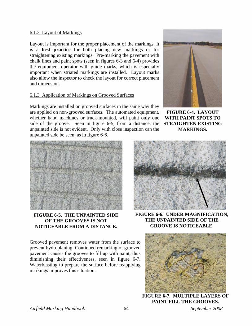
Airfield Marking Handbook September 2008 64
FIGURE 6-7. MULTIPLE LAYERS OF PAINT FILL THE GROOVES.
6.1.2 Layout of Markings Layout is important for the proper placement of the markings. It is a best practice for both placing new markings or for straightening existing markings. Pre-marking the pavement with chalk lines and paint spots (seen in figures 6-3 and 6-4) provides the equipment operator with guide marks, which is especially important when striated markings are installed. Layout marks also allow the inspector to check the layout for correct placement and dimension. 6.1.3 Application of Markings on Grooved Surfaces Markings are installed on grooved surfaces in the same way they are applied on non-grooved surfaces. The automated equipment, whether hand machines or truck-mounted, will paint only one side of the groove. Seen in figure 6-5, from a distance, the unpainted side is not evident. Only with close inspection can the unpainted side be seen, as in figure 6-6.
Grooved pavement removes water from the surface to prevent hydroplaning. Continued remarking of grooved pavement causes the grooves to fill up with paint, thus diminishing their effectiveness, seen in figure 6-7. Waterblasting to prepare the surface before reapplying markings improves this situation.
FIGURE 6-4. LAYOUT WITH PAINT SPOTS TO STRAIGHTEN EXISTING
MARKINGS.
FIGURE 6-5. THE UNPAINTED SIDE OF THE GROOVES IS NOT
NOTICEABLE FROM A DISTANCE.
FIGURE 6-6. UNDER MAGNIFICATION, THE UNPAINTED SIDE OF THE
GROOVE IS NOTICEABLE.

Airfield Marking Handbook September 2008 65
6.1.4 Application of Markings on Porous Friction Course (PFC) Installing markings on PFC is generally done in two passes, one in each direction, in order to coat all sides of the larger aggregate designed in the PFC asphalt mix. An initial coat applied in one direction at half rate without glass beads, followed by a second coat in the other direction applied at full rate with glass beads, coats all sides of the aggregate in the asphalt. Additionally, the first coat acts as a primer, which is a best practice. It seals the oils in the asphalt, keeping the white paint from turning brown. 6.1.5 Coverage Rates Coverage rates (film thickness or bead distribution) of the material are important. Most manufacturers recommend coverage rates expected from a gallon of material or a pound of beads. Local government agencies occasionally specify their own coverage rates, which can differ from those recommended either by the manufacturer or the guidance literature. A project designer should be wary of specifying different coverage rates than those recommended by the manufacturer or the guidance literature. In most cases, either more or less than recommended is not advisable. Coverage rates can be greatly affected by the speed of the equipment. If the speed is too fast, the film thickness will be too thin to anchor glass beads, and the coating will wear too quickly. If the equipment moves too slowly, the resulting heavy film may cause the coating to crack or not cure properly, as seen in figures 6-8 and 6-9. Close attention to proper coverage rates is a best practice.
6.2 REPAINT EXISTING MARKINGS “Repaint” means painting over existing markings after cleaning the surface. In this case, layout for the markings being applied will be minimal, unless the preparation obscured their location. If more than 10 percent of the markings require layout to straighten those out of alignment, this should be stated in the plans and/or specifications for the applicator to plan to make time to do it.
FIGURE 6-8. TOO MUCH PAINT WAS APPLIED IN OUTLINED AREA.
FIGURE 6-9. THICK COATING CRACKED, CAUSING PAVEMENT TO
CRACK AS WELL.

Airfield Marking Handbook September 2008 66
6.2.1 Surface Preparation The most overlooked condition requiring surface preparation is the condition before repainting markings. Airfield markings are exposed to all of the worst elements: rain, heat, extreme cold, chemicals, heavy loads and/or infrequent use, ultra violet light, algae, and other stresses. Each element can individually stress the markings on the pavement; but in combination, they can result in the marking materials becoming aged, faded, brittle, cracked, and worn. Removing the existing layers affected by such elements gives the new coating a better surface on which to bond, and this is a best practice. Many airports repaint their markings at least once per year. Some only do “high-maintenance” markings, such as the runway and taxiway centerlines, but in most cases very little if any surface preparation is performed. The results are varied, but all perpetuate the maintenance cycle.
6.2.2 Application on Different Pavement Types Airport pavements are made up of two basic types: portland cement concrete (PCC) and asphaltic cement concrete (ACC). As the pavements wear, other surface treatments are applied, all of which accept the application of markings, but some react differently than others. The following paragraphs describe some of the different surfaces encountered and the observed performance of markings on them. 6.2.2.1 Concrete If concrete is new or unmarked, epoxy performs well and is very durable. Solvent and water-borne paints perform well. Water-borne paints have been improved: better polymers have been developed that improve the bond of the material to the pavement and provide greater flexibility and elasticity of the marking. As long as the water-borne marking is installed correctly, its life expectancy should be two years or longer, depending on the volume of traffic. 6.2.2.2 Asphalt Most materials bond well to asphalt, but asphalt is more susceptible to damage due to different stresses of the coatings on the surface. For highways, thermoplastic is a popular material because it melts the asphalt and bonds to it as both the surface and the marking cool. But for airfields, current thermoplastic formulations are confined to narrow markings, (i.e., vehicle roadways, taxiway lines, or apron markings). Currently no agency lists thermoplastic as an approved material for airfield markings.

Airfield Marking Handbook September 2008 67
Solvent paints (TT-P-115 and TT-P-85) were a government standard until the mid 1980s when the water-borne paints were introduced in response to environmental concerns. Solvent paints caused severe cracking of both paint and asphalt, as seen in figures 6-10 and 6-11.
6.2.2.3 Seal Coat Water-borne paints are the best material to use on seal coats, due to their lack of “reactivity.” In some locales where rust discoloration is an issue, the application of a seal coat inhibits the rust discoloration on white markings. Coating the asphalt aggregate keeps the contaminants sealed, preventing the iron from affecting the markings. Water-borne paints can cause the asphalt to lift or crack next to the marking edge due to stresses created during the curing of the paint. This usually occurs when the asphalt is freshly applied or when the water-borne paint is applied too thickly. Figure 6-12 shows a one-year-old marking applied when the asphalt was new. Cracking is evident where paint guns overlapped.
FIGURE 6-11. ENLARGED PORTION OF CRACKED
ASPHALT.
FIGURE 6-10. OLD SOLVENT PAINT CURLED, CRACKING THE ASPHALT TO WHICH IT WAS
BONDED.
FIGURE 6-12. THE HEAVIER PAINT IN THE OVERLAP AREA CAUSED THE
PAINT AND THE ASPHALT TO CRACK.

Airfield Marking Handbook September 2008 68
6.2.2.4 Pavement Rejuvenator Rejuvenator is generally applied around markings, not over them, because neither one will bond well to the other. Pavement rejuvenator is designed to penetrate into asphalt, restoring life to the pavement. Any paint coating will present a barrier to the rejuvenating products, so it must either be 80 to 85 percent removed, or circumvented. 6.2.2.5 Crack Sealant Crack sealant is made of bituminous material, and paints do not bond well to it. Additionally, crack sealant discolors the white paint, as oils are still present in it, evident in figure 6-13. 6.3 STRIATED MARKINGS Striated markings are stripes of even width separated by spaces of even width within the area of a standard runway marking. The theory of the striated marking is that the space exposes pavement that absorbs heat from the sun more quickly than the white marking. In areas of the country where frozen precipitation is common, the exposed pavement hastens the melting of the ice or snow, helping to prevent “frost-heave” of the pavement. There is not a specific stripe width for the striations, but they can range between 4 to 6 inches wide. With a 6-inch striation, a 36-inch wide centerline marking becomes 42 inches, because the edges of the marking must begin and end with a stripe: 4 stripes, 3 spaces (4 lines + 3 spaces) × 6 inches = 42 inches. However, a 4-inch striation would be applied exactly 36-inches wide with five stripes and four spaces: (5 lines + 4 spaces) × 4 inches = 36 inches. Seen in figures 6-14 and 6-15, when a striated marking is remarked, the existing striations are often not matched exactly. Eventually, no pavement is exposed, which negates the reason for the striations.
FIGURE 6-13. JOINT MATERIAL DISCOLORS THE WHITE PAINT.
FIGURE 6-15. 6-INCH STRIATIONS. FIGURE 6-14. 4-INCH
STRIATIONS.

Airfield Marking Handbook September 2008 69
Striated markings are less visible, particularly at night, because half the standard marking dimension is bare pavement. For this reason, the FAA states that more frequent maintenance is required to keep this marking effective.
“More frequent maintenance” means more paint applications, which leads to paint build up. The striations become ridges, susceptible to being scraped off by snowplows. As the markings are scraped off during the course of the winter, they become even less visible during either day or night, resulting in the loss of the markings as an effective navaid. As seen in figure 6-16, the leading edge of the marking has been virtually removed by the snowplow. “More frequent maintenance” should include surface preparation to remove loose and poorly bonded paint. In more severe cases, where paint has been allowed to build up, paint removal should be required. From a pilot’s perspective, the “acquisition” of a runway with striated markings, on a clear night without the benefit of runway centerline lights, happens within the last 100 feet of elevation. The markings seen from the ground (figure 6-17) are poor, reducing nighttime visibility.
FIGURE 6-17. STRIATED MARKINGS ARE NOT AS VISIBLE AS SOLID MARKINGS; AND WHEN
BEADS ARE POORLY APPLIED, THEY ARE DIFFICULT TO SEE DURING LOW-VISIBILITY.
FIGURE 6-16. LAYERED STRIATIONS ON THE
SIDELINE WERE SCRAPED OFF BY SNOWPLOWS.

Airfield Marking Handbook September 2008 70
6.4 TEMPORARY MARKINGS Temporary markings are by definition being applied for a limited period of time. The coverage rate and choice of materials depend on several factors.
• The length of time the markings will be needed.
• The kind of traffic or wear they will sustain.
• Prevailing weather conditions.
• Whether or not they will be removed.
• Whether it is a thin “temporary” (primer) coat in the permanent location. Most temporary airfield markings are installed using the standard water-borne traffic paint, TT-P-1952. Thinning the paint is not recommended. Applying it at half the coverage rate is standard for temporary markings, (i.e., 230 square feet per gallon versus the full rate of 115 square feet per gallon). 6.4.1 Coating Thickness (Film Thickness) of Temporary Markings The coverage rate and film thickness of temporary markings will be based on the length of time the markings must be in place. If the temporary markings must be visible at night, glass beads may be needed, and a 12–15 mil wet film thickness is required for anchorage of the spheres, assuming TT-B-1325, Type I or III glass beads is used. Coating thickness can be altered by increasing the speed of application, changing the gun tip sizes, changing the pressure on the pump or tank, or a combination of these methods. The thinner the coating, the easier it is to remove in most cases. Much depends upon the coarseness of the pavement, or how absorbent it was when the marking was applied. A coarse or rough pavement will have peaks and valleys. Wet coatings will gravitate toward the valleys, leaving the peaks with thinner coatings. New asphalt is absorbent, and coatings soak into the fresh pavement. A primer (temporary) coat at half thickness without glass beads will seal the pavement, and is a best practice. One method to facilitate removing temporary markings is to apply a layer of curing compound on the pavement before the temporary markings are installed, whether the pavement is concrete or asphalt. The wax-based curing compound acts as a “temporary bond” to the pavement, and until it flakes off or is intentionally removed, the paint will adhere to it. If the temporary marking is subjected to heavy traffic, the marking may have to be reapplied if it flakes off prematurely.

Airfield Marking Handbook September 2008 71
6.4.2 Application of Markings Under Adverse (Cold) Weather Conditions There will always be situations when markings must be applied to open an airfield surface to traffic to comply with a schedule or safety requirement. If the markings are applied under adverse, (e.g., cold or wet conditions), a best practice is to install the markings with a temporary coating; then when weather conditions are better, the permanent markings can be applied. If the temporary coating is not well bonded, remove the peeling portions before applying the permanent coating. 6.4.3 Glass Beads Glass beads usually are not used on temporary markings. However, if traffic will use the area during darkness or low-visibility conditions, consideration should be given to applying a full coat with glass beads to enhance visibility and situational awareness. 6.5 MARKING EQUIPMENT Equipment for applying pavement markings falls into two general categories: (1) airless systems and (2) pneumatic or air-atomized systems. Either type can be mounted on trucks; skids that can be loaded and unloaded onto pickups or flatbed trucks; small tractors or vehicles; and hand push machines. The airless and air spray categories include features such as hydraulic-powered airless, air-powered airless, pumper-style air spray, and pressurized-tank air spray. 6.5.1 General Characteristics of Pavement Marking Equipment: Whether pneumatic or airless, striping equipment has similar characteristics and challenges. 6.5.1.1 Heated Systems The permanently configured striping truck can be equipped with heat exchangers. Heat exchangers warm the material to approximately 100–120 F. Heating the paint accelerates the “dry to no track” time to approximately one minute, preventing other construction traffic from tracking the markings. However, since the “no track” condition happens faster, the glass beads must be applied simultaneously with the paint application to ensure the beads will anchor and not bounce off the dry film. Paint viscosity thins when heated, flowing more uniformly. When the material is cold, it thickens, resulting in changed line widths and restricted paint flow. Heating the paint does not alter the requirements of either the air or the surface temperatures. If the outside temperature is below 50 F, application of the standard water-borne or solvent-borne paints is not advisable, regardless of the temperature of the material. When the heated material contacts cold pavement, the paint quickly cools to the pavement surface temperature, which if below 50 F, compromises the durability of the marking.

Airfield Marking Handbook September 2008 72
FIGURE 6-19. AIRLESS FAN WITH TIP.
FIGURE 6-18. AIRLESS SPRAY TIP.
6.5.1.2 Housekeeping of the Equipment Good housekeeping is vital for the efficient operation of striping equipment. Water-borne paint should not remain in the tanks, pumps, or lines for longer than 3 to 4 hours, especially when they are partially filled and exposed to high heat, because doing so may cause the paint to harden, resulting in considerable clean out before the equipment can be used again. Using in-line filters or strainers is important to keep the paint free of debris that can clog the paint guns or lines, restricting flow. On an airless system, the most critical location for a Y-strainer is at the inlet of the high-pressure paint pump. For an atomized system, the strainer should be placed before the material manifold leading to the guns. Different binders should not be mixed together. If a solvent paint is in the system, water-borne paint should not be added until the tanks and lines are thoroughly cleaned. Traffic paint manufacturers often recommend a multiple-step procedure involving a series of compatible flushing liquids to perform this switchover. A very small amount of all-purpose cleaner in the clean-out (water) tank helps remove water-borne paint from the tanks and lines, thus preventing a build up of paint film, which can restrict the flow of the material through the system. 6.5.2 Airless Equipment The term “airless” refers to a pumping system that applies paint at approximately 1500–3300 psi without “atomizing air” to disperse the paint particles in a line. An airless gun has a small tip, as seen in figures 6-18 and 6-19. The tips are identified with a three-digit code, (e.g., 421). The “4” represents half of the maximum line width expected from the tip, or 8 inches. However, it is advisable to multiply that number by one and one-half for the recommended line width (6 inches), because striving for 8-inches results in a thinner paint film on the edges of the line. The second two digits (“21”) represent the size of the aperture of the tip in thousandths of an inch. The greater the size of the tip the higher the paint volume and conversely, the smaller the size the lower the paint volume. In addition to the tip size, the speed of the machine installing the marking as well as the pump pressure will affect the volume of material flow and the film thickness of the line. If multiple

Airfield Marking Handbook September 2008 73
FIGURE 6-21. AIRLESS PAINT GUNS AND BEAD GUNS APPLYING MATERIAL TO PAVEMENT.
FIGURE 6-20. AIRLESS PAINT GUNS AND GLASS BEAD GUNS MOUNTED
TO TRUCK ON CARRIAGE.
guns are set up to paint wider markings, the film thickness where the guns overlap must be uniform with the rest of the marking. On truck-mounted units, glass bead guns are arranged to apply the beads onto the wet paint simultaneously, pictured in figures 6-20 and 6-21.
6.5.2.1 Skid-Mounted Equipment Some skid-mounted equipment can be moved on and off a truck. This equipment is capable of applying two colors simultaneously, making it quite attractive to the airport maintenance crew responsible for outlining yellow taxiway markings with black for contrast, figure 6-22. The equipment also can be set up with skip-mechanisms, allowing the operators to dial in a marking pattern that will activate the paint and glass bead guns automatically when the truck begins to move. This is useful for airports that must maintain non-movement boundary markings with the 3-foot dash patterns, or the enhanced taxiway centerlines with the 9-foot dashes and 3-foot spaces seen in figure 6-23.
FIGURE 6-23. THREE PAINT GUNS AND FOUR BEAD GUNS
APPLIED THE YELLOW PATTERN IN ONE PASS.
FIGURE 6-22. SKID MOUNTED PAINT RIG APPLIED BLACK
BACKGROUND FOR TAXIWAY CENTERLINE IN FIGURE 6-23.

Airfield Marking Handbook September 2008 74
FIGURE 6-26. LARGE MATERIAL TOTE.
FIGURE 6-25. TRUCK MOUNTED STRIPING EQUIPMENT WITH
LARGE MATERIAL TANKS.
6.5.2.2 Permanently Truck-Mounted Equipment Truck-mounted equipment (seen in figure 6-24) is more expensive for airports to own, because it is specialized and can only be used for one purpose. However, at busy airports the equipment is used frequently, and not having to reconnect equipment to the truck each time is helpful. Pavement-marking contractors usually have truck-mounted systems, which hold a larger volume of material, making the equipment more productive. Like the skid-mounted unit, this equipment can apply multiple colors simultaneously with or without glass beads. Generally the truck-mounted equipment has a movable carriage, and the operator can steer around radii on the taxiways, turning onto other taxiways and runways. For both the skid-mounted large truck and the permanent truck-mounted equipment seen in figure 6-25, larger supplies of material can be loaded onto the truck, allowing more production time before stopping to “re-load” or fill with more material. Trucks can load from “totes,” seen in figure 6-26, or large paint storage tanks to reduce the amount of waste resulting from 55-gallon drums. Drums are not cost-effective to recycle, and they must be disposed of at landfills. Totes can be recycled with the manufacturer several times, contributing to conservation. However, it is difficult to quantify amounts of material in the totes, so verifying material usage can be a problem. 6.5.2.3 Other Long-Line Machines Equipment manufacturers have developed smaller units (as shown in figure 6-27), which are suitable for most applications, depending upon the skill of the operator. However, the shorter the striping unit, and the closer the carriage, is to the front of the vehicle the more difficult it is to
FIGURE 6-24. TRUCK-MOUNTED AIRPORT STRIPING EQUIPMENT.

Airfield Marking Handbook September 2008 75
FIGURE 6-28. FOUR PNEUMATIC (ATOMIZED) PAINT GUNS APPLYING A
3-FOOT WIDE PATTERN.
keep lines straight. Speed also becomes more variable unless a device is installed to regulate it. Speed affects coverage rates. 6.5.3 Pneumatic or Air-Atomized Striping Systems Pneumatic or air-atomized striping systems use (1) air compressor(s) that pressurize tanks, pushing the material through supply lines and down to the gun(s), figure 6-28, or (2) pumper-style units. According to one equipment manufacturer, the pumper unit can integrate a material-monitoring system, utilizing stroke counters to provide gallon readings. One advantage of the pumper-style units is the zero-pressure material tanks, which are not as heavy as pressure pots. Pumper systems use the diaphragm-loading pumps, seen in figure 6-29, to pressurize the paint lines leading to the guns on the carriage. At the gun, atomized air is introduced at the tip, just past the fluid nozzle where the material enters a chamber. Air breaks up the paint particles, forcing them through the gun tip in a fan pattern, (seen in figure 6-28).
Pneumatic systems are suitable for water-borne and solvent paints. Using the waterborne paint (TT-P-1952) requires the use of stainless steel tanks and compatible paint lines to prevent the paint from reacting with the metal tanks, hoses, or other plumbing. Not as susceptible to clogged paint guns and tips as with airless systems, the pneumatic system has larger orifices through which the material is sprayed (figure 6-30). The volume of material sprayed through an air-atomized gun can be controlled by pressure on the paint tank and it can be fine tuned by increasing or
FIGURE 6-27. OTHER LONG-LINE STRIPING EQUIPMENT.
FIGURE 6-29. PNEUMATIC TRUCK-MOUNTED SYSTEM.
FIGURE 6-30. ATOMIZED MATERIAL GUN AIR NOZZLE AND FLUID NOZZLE.

Airfield Marking Handbook September 2008 76
FIGURE 6-31. PRESSURIZED BEAD APPLICATION IN
FOREGROUND, GRAVITY-DROP IN BACKGROUND.
FIGURE 6-32. METAL SCREEN REDUCES BEAD DISPLACEMENT BY AIR
TURBULENCE FROM PAINT GUNS.
decreasing the atomized air. An increase in atomized air will restrict the flow of material; a decrease in air will increase the flow. When marking with multiple guns in an airless unit, it is sometimes difficult to get a uniform film thickness across the marking. With an air-atomized system, fine-tuning the flow of each gun makes this less of an issue. 6.5.4 Pressurized Glass Bead System
Pressurized guns deliver the most uniform flow of beads to the marking, are automatically triggered when the paint guns are activated (a best practice), and achieve the best distribution and embedment (as seen in figure 6-31). The marking in the upper portion of figure 6-31 was applied using gravity-drop bead guns. The marking in the lower portion of the picture was applied using pressurized bead guns. The pressurized method is more uniform, and is a best practice.
Pressurized glass beads are susceptible to moisture, which accumulates in the bead tank. Water vapor collects from humidity in the air or from the warm, compressed air as it expands in the bead tank. Glass beads are very susceptible to moisture and will clump when damp, making bead flow problematic. A series of water traps throughout the pressurized air system will help keep the air free of moisture. A remedy is to put a “pinch” of cornstarch in the tank of beads as they are being loaded. The cornstarch migrates, covering the beads and helping to prevent them from adhering when damp. 6.5.5 Gravity-Drop Glass Bead System A gravity-drop glass bead system can be effective on any striping equipment if the glass bead guns are activated simultaneously with the paint guns, which is a best practice. However, as seen in figure 6-31, the circular-
type bead guns in a gravity-drop system do not always provide the best results. Modifications to improve distribution include tilting the guns or installing screens to help break up the circular pattern, as seen in figure 6-32. Gravity-drop glass beads are applied to the wet marking within seconds of the material being applied. The glass beads, not under pressure, are not as susceptible to becoming damp, but they will be prone to wind displacement and turbulence from the painting operation just in front of it. The metal screen between the paint and bead guns (seen in figure 6-32) prevents the air turbulence from displacing the beads. The bead guns are activated by air, allowing
Metal screen

Airfield Marking Handbook September 2008 77
FIGURE 6-35. SIX-MONTH OLD HOLDING POSITION MARKING
WHERE BEADS WERE HAND-THROWN.
FIGURE 6-34. NEW HOLDING POSITION MARKING WHERE
BEADS WERE HAND-THROWN.
FIGURE 6-36. FERTILIZER SPREADER WAS MODIFIED TO
APPLY GLASS BEADS.
the beads to drop onto the line. When the air stops, the guns close. The bead guns can be adjusted to delay opening or closing, thus timing them to cover all of the marking. 6.5.6 Hand-Applied Method The hand-applied method of applying glass beads must be used in some cases. However, hand-throwing glass beads, demonstrated in figure 6-33, should be avoided as much as possible. (1) They are seldom “thrown” evenly, (2) they are often thrown after the paint has already “filmed over,” preventing proper embedment, and (3) the glass beads are broadcast on the surrounding pavement, increasing the clean up that will be needed, as well as creating a potential risk of someone slipping. The holding position marking in figure 6-34 is new, yet hand-thrown beads appear uneven. Only some of the hand-thrown beads remain (as shown in figure 6-35), after just six months of wear. Resourceful airport personnel and contractors have developed “low-tech” methods for applying beads. Using a modified fertilizer spreader, seen in figure 6-36, is difficult to judge coverage rate; and bead embedment is still an issue. Because it is mounted on wheels, the applicator must exercise caution when moving this equipment over wet paint.
FIGURE 6-33. HAND-THROWN GLASS BEAD APPLICATION IS UNEVEN,
POORLY DISTRIBUTED, AND POORLY EMBEDDED.

Airfield Marking Handbook September 2008 78
FIGURE 6-38. THE SAME MARKING AS IN FIGURE 6-37 DURING DAYLIGHT.
FIGURE 6-37. BORDER WAS APPLIED WITH HAND-MACHINE
AND BEADS WERE HAND-THROWN.
6.6 HAND MACHINES Hand machines are used for detail markings, such as surface-painted signs, holding position markings, and sometimes runway designation numerals. Some airports use these small
machines, (either push-type or self-propelled) to border larger markings that are then filled in with a larger paint truck, evident in figure 6-37. Figure 6-38 is the same marking seen in daylight. The difference in application of the border with hand-thrown beads is evident at night. 6.6.1 Airless Hand Machines Airless hand machines, similar to the truck- mounted systems, can be pushed or self-propelled. When equipped with large pumps, these machines can paint a line up to 12-inches wide or they can paint two 6-inch lines simultaneously. Lines that are applied wider than 12 inches in a single pass must be carefully monitored for uniform film thickness across the entire line. A “sulky” or motorized cart attached to the machine converts it to a self-propelled unit, seen in figure 6-39. Very maneuverable, a two-gun airless machine can work quickly. This equipment, traveling at an appropriate speed and applying materials at the right coverage rate is effective, especially when equipped with glass bead guns that automatically dispense the beads in the paint, a best practice. 6.6.2 Pneumatic (Air-Atomized Equipment) Air-atomized push equipment, which functions like the truck-mounted systems, is generally equipped with a single material gun. A larger compressor is necessary to operate two paint guns,
FIGURE 6-39. AN AIRLESS MACHINE WITH A MOTORIZED
“SULKY” APPLIES MARKING WITH AUTOMATIC GLASS BEAD GUNS.

Airfield Marking Handbook September 2008 79
making the machine bigger and heavier. It is able to paint detail work that truck-mounted systems cannot do as effectively. Automatic glass bead dispensers are integral to the air-atomized hand machine, a best practice, because the air supply needed to activate the bead gun is part of the system. 6.6.3 Hand Machines and Glass Bead Application Glass bead systems for hand machines generally fall into two categories: gravity fed or hand-thrown. However, at least one equipment manufacturer supplies a pressurized system requiring a compressor and pressurized bead tank, making the machine heavy. Gravity-fed systems use either cable or air activation to trigger the beads. Bead dispensers for airless systems can be included, but the operators often disable these when the apparatus malfunctions. A bicycle brake cable is normally used to activate the bead gun at the same time the paint gun goes on. As dirt, paint, dust, oil, and other substances accumulate on the cable, the trigger begins to slip, failing to activate the bead gun. A considerable percentage of airport personnel using airless hand machines disable the bead dispensers, and use watering cans, fertilizer spreaders, or their hands to throw the beads on the markings, a poor practice. Figure 6-40 depicts an airless machine with a 12-inch bead dispenser that opens automatically when the paint gun comes on. Notice the hand-built windscreen (shroud) around the bead dispenser that blocks the wind from displacing the beads, a best practice. Pneumatic or air-atomized machines generally have a 5 to 10-gallon paint tank and an integrated glass bead hopper with a bead dispenser. The beads are activated by compressed air that triggers the bead gun, shown in figure 6-41, and they can be delayed to go on and off with the turn of a valve. A gravity-fed system is usually used for both airless and pneumatic small paint machines; a much larger compressor would be needed to pressurize a tank. Weight is a main consideration when equipment is pushed and maneuvered by hand.
FIGURE 6-40. GLASS BEAD DISPENSER HAS BEEN MODIFIED
WITH A CARDBOARD WINDSCREEN.
FIGURE 6-41. GLASS BEAD DISPENSER ON AN ATOMIZED HAND
MACHINE.
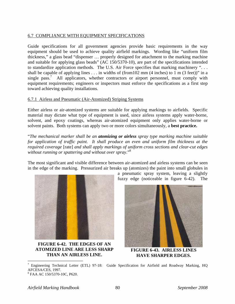
Airfield Marking Handbook September 2008 80
6.7 COMPLIANCE WITH EQUIPMENT SPECIFICATIONS Guide specifications for all government agencies provide basic requirements in the way equipment should be used to achieve quality airfield markings. Wording like “uniform film thickness,” a glass bead “dispenser … properly designed for attachment to the marking machine and suitable for applying glass beads” (AC 150/5370-10), are part of the specifications intended to standardize application methods. The U.S. Air Force specifies that marking machinery “. . . shall be capable of applying lines . . . in widths of (from102 mm (4 inches) to 1 m (3 feet))” in a single pass.7 All applicators, whether contractors or airport personnel, must comply with equipment requirements; engineers or inspectors must enforce the specifications as a first step toward achieving quality installations. 6.7.1 Airless and Pneumatic (Air-Atomized) Striping Systems Either airless or air-atomized systems are suitable for applying markings to airfields. Specific material may dictate what type of equipment is used, since airless systems apply water-borne, solvent, and epoxy coatings, whereas air-atomized equipment only applies water-borne or solvent paints. Both systems can apply two or more colors simultaneously, a best practice. “The mechanical marker shall be an atomizing or airless spray type marking machine suitable for application of traffic paint. It shall produce an even and uniform film thickness at the required coverage [rate] and shall apply markings of uniform cross sections and clear-cut edges without running or spattering and without over spray.”8 The most significant and visible difference between air-atomized and airless systems can be seen in the edge of the marking. Pressurized air breaks up (atomizes) the paint into small globules in
a pneumatic spray system, leaving a slightly fuzzy edge (noticeable in figure 6-42). The
7 Engineering Technical Letter (ETL) 97-18: Guide Specification for Airfield and Roadway Marking, HQ AFCESA/CES, 1997. 8 FAA AC 150/5370-10C, P620.
FIGURE 6-42. THE EDGES OF AN ATOMIZED LINE ARE LESS SHARP
THAN AN AIRLESS LINE. FIGURE 6-43. AIRLESS LINES
HAVE SHARPER EDGES.

Airfield Marking Handbook September 2008 81
airless spray uses higher pressure and smaller orifices to break the paint into smaller globules and lays the marking down like a ribbon of paint with sharper edges (seen in figure 6-43). From a distance, the edges of the air-atomized markings appear fairly sharp. The “fuzzy” edge is made of thin drops of paint, just a “dusting,” that will wear off quickly. The measured width of an atomized line should not include the “fuzzy” edge. Over spray: The “fuzziness” of the air-atomized system does not constitute over spray. Over spray occurs when conditions are windy and the striping machine does not have adequate shrouds to keep the materials from being displaced. The yellow haze to the left of the taxiway edge line in figures 6-44 and 6-45 is an example of over spray. Another cause of over spray can be from thinning the paint. Specifications as well as material suppliers state that the “paint shall not be thinned” since it changes the composition of the material, resulting in longer dry time and coverage (dry film thickness), as well as under-embedment of the glass beads.
6.7.2 Uniform Film Thickness and Cross-Section Guidance literature recommends using between 100 to 121 square feet per gallon of both the water-borne and solvent paints. That coverage rate computes to a 12 to 16 mil wet film. A wet film thickness gauge can be used to measure the wet coating without glass beads. Each paint gun must be calibrated to apply the proper coverage rate, and is a best practice. This process will help to achieve uniform film thickness across the entire marking, which is also a best practice. In many cases, markings can be applied using the right coverage rates in terms of square feet per gallon, but the markings, from six inches to thirty feet wide, may not exhibit a uniform film thickness. The following factors contribute to this issue. 6.7.2.1 Material Fluid Tips Are Worn Material flowing through a tip or fluid nozzle is abrasive. The orifice begins to wear after many gallons of material pass through, and it should be monitored closely for signs of wear. Also, when cleaning out the material lines and guns, remove the tips first, because the water flow will contribute to faster wear. Though new tips are expensive, replacing them regularly improves the
FIGURE 6-45. CLOSE UP OF OVER SPRAY IN FIGURE 6-44.
FIGURE 6-44. OVER SPRAY CAUSED BY WIND OR THINNED PAINT, OR
BOTH.

Airfield Marking Handbook September 2008 82
quality of the markings. Worn airless tips can exhibit an unevenness of the line, (either heavy material in the middle and lighter material on the edges, or lighter in the middle and heavier on one or more edges). Worn pneumatic tips result in “fuzzier” edges with heavier material in the middle or edges of the line. When the wet film thickness is not uniform across the entire width of the line, the marking wears unevenly. The thinner areas will wear off faster, and if glass beads are used, proper embedment will only occur on the areas of the line with proper film thickness. 6.7.2.2 Material Guns have Line Width Limitations In many instances, striping machines are set up to apply the widest marking possible out of a single gun, and the result is that the line does not produce a uniform film thickness. Local highway marking contractors are often hired to maintain airfield markings. Their equipment is designed to apply four- to six-inch road lines, not the wider airfield markings. Observed in figures 6-46 and 6-47, this equipment is equipped with two airless paint guns on the left carriage. In figure 6-46, two paint guns are raised to paint a 19-inch line. Only in the middle of each sprayed line is the paint of sufficient film thickness. The use of more material guns, will improve the likelihood of uniform film thickness across the entire marking; this is a best practice. A larger tip size in an airless system also will increase the amount of material flow, as does increasing the pump pressure. Naturally, the speed of the machine can affect the film thickness too. The glass bead guns in figure 6-47 are raised and spray upward and backward from the paint spray to achieve a wider spray of beads. Wind easily displaces the light glass beads; occasionally they miss the marking entirely. Glass beads cannot embed in an insufficient film thickness; thus the thinner markings will be compromised for nighttime visibility soon after application. FIGURE 6-46. UNEVEN MATERIAL
DISTRIBUTION, LIGHT ON THE EDGES OF EACH PAINT GUN.
FIGURE 6-47. GLASS BEAD DISPENSERS ADJUSTED TOO
HIGH.

Airfield Marking Handbook September 2008 83
Figure 6-48 shows two raised paint guns (far left); the graphic demonstrates what a cross section of figure 6-46 would look like (far right). In an air-atomized system, different-sized fluid nozzles will yield a greater or lesser volume of material, as will adjusting the needle setting, increasing the material tank pressure, adjusting the proportion of atomization air to the paint, or just slowing down the machine. 6.7.2.3 Equipment Moves Too Fast The normal tendency is to drive or walk too fast, resulting in a wet film thickness too thin to support the glass beads being dropped onto it, and the marking wears prematurely. One of the more common reasons for repeated maintenance is excessive speed during application, which causes inadequate film thickness and poor bead distribution and embedment. High speed also causes glass beads to hit and roll, coating them with wet paint, thus reducing retro-reflectivity by preventing light from entering the glass sphere and returning to the source.
6.7.3 Width of Line in Single Pass The U.S. Air Force ETL 97-18 prescribes the striping equipment shall be capable of applying a marking from four to thirty-six inches in width in a single pass. This is a best practice and should be adopted in all specifications for the following reasons: • On a precision-marked runway, more than half of the markings are three-feet wide, and
can be painted in a single pass. • The markings appear to be more uniform with fewer “retracing” deviations.
FIGURE 6-48. IRREGULAR FILM THICKNESS ACROSS THE LINE PERFORMS POORLY.

Airfield Marking Handbook September 2008 84
FIGURE 6-49. VISIBILITY OF THE “R” IS POOR AT NIGHT.
FIGURE 6-50. THE “R” IS VISIBLE IN THE EARLY
MORNING LIGHT.
• A wider spray pattern equates to less time on the airfield, reducing the amount of “down time” for operations.
• There is better use of time and resources for airport personnel who apply their own
markings. • Caution should be exercised if fewer than four material guns are being used for a 36-inch
wide marking. Monitor for the material being applied at the specified film thickness and uniformity. Speed also will affect the film thickness of the material.
6.7.4 Glass Beads The specified and proper application of glass beads by all applicators will serve the pilot or others operating on the airfield surface during darkness or low visibility conditions. In the daytime, markings appear uniform and convey information to the pilot or airfield operator. At night, only properly applied glass beads will give the surface operators the same information.
Figure 6-49 demonstrates markings that are barely visible at night but visible during daylight (figure 6-50). When the application of the markings is done poorly, their life expectancy is short, and visibility to the pilot is greatly reduced at night. Hand-thrown beads are a poor practice. Seen in figure 6-49 and 6-50, the “R” was hand-sprayed, the paint gun moved too quickly, and proper wet film thickness was not achieved. The beads were hand-thrown unevenly and were not embedded well in the thin coating. The paint forms a dry “no track” film quickly, preventing hand-thrown glass beads from

Airfield Marking Handbook September 2008 85
FIGURE 6-52. NIGHTTIME VISIBILITY OF FIGURE 6-51 IS EXCELLENT.
FIGURE 6-51. DAYTIME VISIBILITY IS EXCELLENT.
FIGURE 6-53. LASER POINTER.
Laser pointer
FIGURE 6-54. MECHANICAL POINTER.
anchoring or embedding properly. Frequent remarking becomes necessary due to reduced performance, resulting in paint build up, traffic interruptions, extra labor, and increased material usage, as well as poor nighttime visibility, and compromised safety. The “4” seen in figures 6-51 and 6-52, is visible both during daylight and darkness. The numeral was applied with an air-atomized truck, spraying a 3-foot pass with automatic, pressurized bead dispensers: all best practices.
6.7.5 Straightness Tolerance Painting markings straight or in compliance with specification standards generally can be attributed to the existing markings or layout being straight. However, it can also be a function of the skill of the driver/operator as well as the effectiveness of a pointer system, which can be seen in figures 6-53, 6-54, 6-55 and 6-56. Effective pointer systems are a best practice.
Pointer systems help the driver or equipment operator keep the marking within the specified straightness tolerance (no deviation greater than ½-inch in 50 feet). Laser pointers can follow an adjacent line to create one that is parallel, and mechanical pointers can be suspended either from

Airfield Marking Handbook September 2008 86
Mirror and pointer
FIGURE 6-55. POINTER WITH MIRROR. FIGURE 6-56. PORTABLE LASER
POINTER.
a truck or track on a wheel extended in front of a truck. Mechanical pointers are mounted on a part of the equipment within view of the driver. In all cases, pointers are essential equipment that assist in good alignment and are a best practice. Other types of guidance systems include closed-circuit projection of the carriage in the cab of the truck for the driver to follow. Figure 6-55 demonstrates the use of a mirror in front of the material guns to guide the driver. The portable laser pointer shown in figure 6-56 was observed being used on a motorized airless machine; it was then moved to the side-view mirror frame on the paint truck. It is battery powered and projects a green laser beam onto the pavement to help the operator track the line. 6.8 EQUIPMENT COMPATIBILITY Specific equipment is needed to properly apply different materials. Airless equipment is used for water-borne paint, solvent paint, and epoxy. Also, for epoxy, calibrated pumps mix the two components during the airless application process. Water-borne paint (U.S. Federal Specification TT-P-1952) is the predominant material used on all U.S. airports, both domestic and military. The paint requires the use of stainless steel tanks, plumbing, and Teflon®-coated material lines. This paint reacts with regular steel, brass, and galvanized metals. Allowing paint to remain in the tanks or lines causes it to thicken or harden; this is especially true in hot temperatures and when lines or tanks are partially filled. Good housekeeping prevents problems on the job. 6.9 HOUSEKEEPING Housekeeping is a necessary chore with any operation. Developing a discipline of good habits, from keeping the work area clean to cleaning out equipment, leads to better production and is a best practice.

Airfield Marking Handbook September 2008 87
6.9.1 Clean Up of Excess Materials or Spills Clean up of excess materials or spills is a good practice for any industry. When working in an airfield environment, it is especially important to remain focused on such details. At least one airport incident involved the ingestion of glass beads into jet engines, precipitating a lengthy debate and great expense to determine if the engines were damaged. Although no significant engine damage was detected, the incident raised the awareness of the need for clean up after an airfield marking project. Additionally, preventing spills of paint or other materials prevents an unsightly mess. Some airport personnel who apply their own airfield markings have a designated test striping area for setting guns and marking patterns, checking glass bead distribution, and overall quality of the markings. Resembling a modern work of art (seen in figure 6-57), the test pavement area is a great asset for the installers and is a best practice. Contractors seldom have the luxury of applying test lines to the pavement, and often they have issues as to where to set up the material guns. One contractor was observed using tar paper to run test lines and adjust both paint and bead guns (seen in figure 6-58). This method prevented unwanted markings and drips from getting on the pavement. Although beads have fallen onto the pavement, they can be swept up, and the area can be blown clean of any material. This is a best practice. 6.9.2 Check for FOD, Dropped Tools, Materials, Etc. Attention should be paid to any object that does not belong on airfield pavements, whether it came from the marking operation or not. Hand tools, in particular, should be routinely returned to a specific place (on the truck or in the toolbox) to make certain they are not left on the pavement. Sometimes boards, roofing shingles, light covers, or other materials are used at the ends of markings or to cover lights to prevent unwanted material from getting on surfaces. Metal strips, rebar, or other materials used to protect concrete joints during cleaning or removal operations
FIGURE 6-57. TEST AREA FOR EQUIPMENT SET UP.
FIGURE 6-58 TEST LINES ON TAR PAPER.

Airfield Marking Handbook September 2008 88
must be collected to prevent FOD. Checking and double-checking to make certain all of these materials and supplies are picked up at the end of the work shift is extremely important. 6.9.3 Environmental Issues Attention to the details of compliance with environmental regulations is recommended. It is incumbent upon all to comply with the standards established by federal and local governments, including airports. Although water-borne paint is “environmentally friendly,” in liquid form it can pose a health issue due to its methanol and ammonia content. Careful handling of all materials is important. 6.9.3.1 Hazardous Materials Hazardous materials, such as solvent, epoxy, and methyl methacrylate paints require special handling and care. In the material storage area and when loading or cleaning out equipment, precautions must be taken to contain and mitigate spills or unintended contact with skin or eyes. Additionally, clean up of those materials requires the use of toluene, MEK, naphtha, or other solvents; all of these are hazardous and require personal protective equipment to avoid contact with skin and eyes. These toxic materials become hazardous waste, and they must be contained and disposed of properly. One of the benefits of using water-borne paint is that it is non-hazardous, although there is a “Health” factor of 1 on the label because it includes methanol and ammonia solvents. Once dry, those solvents have evaporated, and the coating is environmentally safe. Clean up of equipment is accomplished with water. Containment of the wastewater is generally required, even though it is considered non-hazardous. 6.9.3.2 Hazardous Waste Hazardous waste generated from an airfield-marking project adds to the cost of the job. However, if a durable marking like epoxy is specified, the additional cost of dealing with both the hazardous material and waste will be included in the planned expenses for the project. Another form of hazardous waste may originate from debris resulting from a paint-removal operation. Most coatings on airfields are lead-free water-borne paint. However, occasionally airfield markings may still contain lead-based paint. All paint removal debris should be tested through a TCLP analysis. This “Toxicity Characteristic Leaching Procedure (TCLP) is designed to determine the mobility of both organic and inorganic analytes present in liquid, solid, and multiphasic wastes. If a ‘solid waste’ fails the test for one or more of these compounds, the waste is considered to be a characteristic hazardous waste – unless an exemption applies. Bear in mind that a characteristic waste may also be a ‘listed’ hazardous waste.”9 During the process of removing the markings, some of the pavement surface, dirt, and other debris can mix with the old paint, thus diluting the debris, and reducing the likelihood of it being 9 http://www.ehso.com/cssepa/TCLP.htm

Airfield Marking Handbook September 2008 89
characterized as hazardous. Although generally not considered hazardous, the majority of water runoff from waterblasting operations for rubber removal, surface preparation, or paint removal should be collected and contained along with other debris. The waste hauler will require a profile of the debris to be removed; profile information will be listed on the manifest. This profile is created from the TCLP analysis. 6.9.3.3 Non-Hazardous Waste Non-hazardous waste falls below the toxicity thresholds for the 40 listed contaminants. Most waste disposal companies require a TCLP analysis to identify the waste before they will move any container. Even if it tests as non-hazardous, some landfills may require special treatment because it is “paint” or because it came from an airport environment. 6.9.3.4 Material and Waste Containers Material containers, whether material totes, drums, or paper bags should be contained and properly disposed of. Totes are often available from paint manufacturers and can be recycled. Additionally, dumpsters, roll-off containers, drums, pails, etc., are often required to be covered at all times, and secondary containment systems may need to be put in place. 6.10 QUALITY CONTROL BY APPLICATOR Quality control in the application of airfield markings is an important aspect of a marking project. Writing good specifications specific to the airport project is beneficial to the airport. All airports are unique; they have different environments, pavements, requirements, and related issues. Verifying that the specified material is being used, applying it at the correct coverage rates, and checking the alignment and position of the markings are elements of good quality control. If these steps are practiced and specifications are enforced, the probability of achieving a quality marking application is greatly increased. 6.10.1 Quantify Completed Work Quantify completed work on a daily basis. The total amount of footage applied should be recorded, including which markings were applied, the amount of material used, and any associated issues. Such documentation will serve the airport well in the event of any incident where the markings are scrutinized. 6.10.2 Calculate Material Usage To calculate material usage, first count all material at the beginning of the work shift. Determine the remaining amount of material at the end of the work shift. The difference will be what was used. Materials in the tanks at the beginning and end of the work shift also should be calculated into the quantities. Record the completed work after a material tank is completely emptied, and/or at the end of the day. With the known amount of square footage installed, divide by the amount of material used,

Airfield Marking Handbook September 2008 90
and compare it to the specified coverage rate. Then divide the amount of glass beads used by the volume of paint or other coating used, and compare this to the specified coverage rate for that type of glass beads. (1) square footage ÷ gallons = paint coverage rate, (2) pounds ÷ gallons = bead coverage rate. If the coverage rates are off, adjustments should be made to pressures, material guns, and/or the speed of the equipment. This monitoring of material usage and coverage rates should be continuous throughout the project, and it is a best practice. 6.10.3 Documentation Documentation is an important detail that many airports do not maintain. Keeping daily records of what was done, who did it, with what equipment, and how much material was used is an indication of being diligent about this important element of airfield safety, and it is a best practice. 6.10.4 Quality Control Tool Kit There are tools and devices that help in maintaining quality control and enforcing standards. 6.10.4.1 Calibration Bucket Calibration is a means of ensuring the correct material flow based on the speed of the machine applying the markings. Both paint and glass bead guns can be measured for the volume of material that flows through each gun in a 10-second interval, and this is a best practice. The amount collected in the container seen in figure 6-59 is compared to an integrated chart. If the amount collected is too little, the gun should be adjusted to allow more material to flow; if the amount is too great, the gun should be adjusted to reduce material flow. Each gun should be tested in this manner. It is assumed that each gun is positioned to apply the same width line as the others. Figure 6-60 shows the calibration bucket being used to check material flow from each bead gun. Close attention must be paid to the speed of the vehicle throughout the course of the work because even a slight increase in speed will affect material coverage rates. Clogs of paper, clumped beads, or other debris may restrict material flow during marking activities.
FIGURE 6-59. CALIBRATION BUCKET FOR GLASS BEADS.
FIGURE 6-60. CALIBRATION OF GLASS BEAD GUNS.

Airfield Marking Handbook September 2008 91
Close monitoring of the markings during application is essential, and is a best practice. 6.10.4.2 Wet Film Gauge A wet film gauge (figure 6-61), although not exact, is a tool used to check the wet film thickness of the paint. This should be done on a relatively smooth surface, such as a metal plate or duct tape applied to the pavement when the test lines are being applied. It should be measured without glass beads. Instructions are found on the gauge. To determine the wet film thickness being applied, the gauge is pressed into the coating at a 90° angle, figure 6-62. If the desired film thickness is 15 mils, the side reading “14, 16, 18, through 30” is used. If the desired film thickness is 60 mils, the side reading 35, 40, 45 through 80” is used. For 15 mils, the coating should cover the “14” tab, but not the “16” tab. If multiple guns are being used, each paint gun should be checked, and if one gun is applying a line greater than 8-inches, the entire line width should be checked for uniformity.
6.10.4.3 Magnifying Glass A magnifying glass is used to check for correct glass bead embedment. If the material film is too thin, the glass beads may not embed properly, and they will dislodge from traffic or other mechanical wear. If the material film is too thick, the glass beads may over-embed, and the reflectivity values will drop because the light cannot enter the bead and return effectively.
FIGURE 6-61. WET FILM GAUGE. FIGURE 6-62. USE OF WET FILM GAUGE.
FIGURE 6-63. MAGNIFYING GLASS.

Airfield Marking Handbook September 2008 92
FIGURE 6-64. EXCESSIVE WICKING OF PAINT OVER BEADS.
FIGURE 6-65. WICKING MATERIAL OVER BEAD.
In figure 6-63, a magnifying glass is used to check glass bead distribution and embedment. In this case, there is poor glass bead distribution and embedment. A magnifying glass detects other problems, such as excessive “wicking” of the paint over the bead (figures 6-64 and 6-65). Paint gathers up around the bead, giving it a “tree trunk” effect; this reduces reflectivity by covering the glass sphere and preventing light from entering it. This problem can be caused by the absence of a suitable bead coating or the paint formulation.
A magnifying glass can help in diagnosing other issues, such as poor performance of marking materials. In figure 6-66, the paint film disintegrated after only having been in place for 24 hours. 6.10.4.4 Flashlight A flashlight is always useful to keep in the toolbox, because many marking projects are done and inspected at night.
6.10.4.5 Metal Coupons and Duct Tape
FIGURE 6-66. USE MAGNIFYING GLASS TO DETECT COATING
PROBLEMS.
FIGURE 6-67. WET FILM GAUGE ON A METAL COUPON.

Airfield Marking Handbook September 2008 93
FIGURE 6-70. RETROMETER.
FIGURE 6-68. USE DUCT TAPE TO MEASURE WET FILM THICKNESS OF MARKING.
Duct tape placed in the path of the paint machine captures a sample of the painted line which can be checked for proper film thickness.
Metal coupons and duct tape are useful in gauging film thickness of material. Place a metal coupon (as in figure 6-67) in the path of the material guns. Immediately after the material is applied, insert the mil gauge vertically in the wet coating. Different materials have different coverage rates; therefore, they have
greater or lesser wet film thickness requirements. Duct tape also can be used to check film thickness, seen in figure 6-68, although it is not as reliable as the metal coupons. Also, surfaces that have been prepared or had paint removed may need additional sweeping or vacuuming before being remarked. Spread a strip of tape across a cleaned area, press into the pavement (see figure 6-69 – top), then pull the tape up and inspect the underside for signs of grit or other debris, as seen in figure 6-69 (bottom). 6.10.4.6 Retro-reflectivity Measurement Airfield marking retro-reflectivity is measured with a calibrated instrument known as a retro-reflectometer, as seen in figure 6-70. Originally retro-reflectometers were developed for highway use and measure marking retro-reflectivity using a 30-meter viewing geometry. This geometry represents how the driver of a small passenger car would see a pavement marking located 30 meters (98.4 ft) in front of the vehicle. Although the geometry is not the same for aircraft, the device still serves as a relative measure that conveys the effectiveness of an airfield marking for nighttime visibility. It is advisable to take readings at least 24 – 48 hours after installation of the markings. Beads that are partially adhered or not adhered can be detected. Waiting for one or two days to take readings gives water-borne paints enough time to cure so that loose beads can be brushed
FIGURE 6-69. PULL TEST.

Airfield Marking Handbook September 2008 94
off the marking prior to taking readings without damaging the film. A new, cured marking lightly swept typically yields higher readings. 6.10.4.7 Color Measurement A colorimeter is a device that measures chromaticity. “The International Commission of Illumination (CIE) has developed the methodology for describing and tabulating colors in a numerical system that is based upon a standard observer. The standard observer is defined by small groups of individuals (about 15–20) that have normal human color vision.”10 The coordinates recorded by the colorimeter in figure 6-71 correspond to a chart designed by the CIE and adopted by the FAA. Recorded readings are plotted on the chart to determine compatibility with the color standards. Color ranges at installation for those normally used on airfields (e.g., white, yellow, red, and green) vary almost imperceptibly. Colors for airports are different than those required for highways. At installation, the markings must fall within the tolerances adopted by the FAA. Another method for comparing colors without expensive equipment and plotting of readings to a chart is the use of color chips. Seen in figure 6-72, three color chips are compared to a red marking; the marking is compared visually for compliance. There are three shades of red; the lightest is on the top of the panel, the exact match is in the middle, and the darkest is on the bottom.
10 Development of Methods for Determining Airport Marking Effectiveness, Holly M. Cyrus, DOT/FAA/AR-TN03/22, March 2003.
FIGURE 6-71. COLORIMETER
FIGURE 6-73. YELLOW COLOR CHIP COMPARED TO YELLOW MARKING. FIGURE 6-72. RED COLOR CHIP
COMPARED TO RED MARKING.

Airfield Marking Handbook September 2008 95
Figure 6-73 displays a yellow marking that, when compared to the color chip, is out of tolerance. The three color chips are more apparent in the yellow coupon; the lightest is on the left, the exact match is in the middle, and the darkest is on the right of the coupon. 6.10.4.8 Grid for Determining Compliance with Degree of Paint Removal A grid with 100 equal squares can be used to measure the degree of paint removal that has been accomplished. If 85 percent paint removal has been specified, only 15 squares or less should contain any of the old coating. In the remaining squares the old coating should have been removed. The grid shown in figure 6-74 is an example of one that can be used for this purpose.
FIGURE 6-74. GRID FOR COMPLIANCE WITH DEGREE OF PAINT REMOVAL.

Airfield Marking Handbook September 2008 96
TABLE 7-1. CHAPTER CONTENTS MAY BENEFIT:
7 INSPECTION Observing test lines at the outset of a marking project, and knowing material quantities, does not ensure that the markings are applied correctly. Inspection plays an essential role in the successful application of airfield markings. Inspection is necessary to ensure that (1) the proper markings are applied, (2) the markings are applied at the correct location, (3) the proper materials are used, and (4) the quality of the marking application meets the appropriate criteria. Chapter 7 describes visual inspection guidelines for monitoring airfield markings. These guidelines identify activities that inspectors should perform as contractors or airport marking personnel apply markings. Table 7-1 indicates the personnel who will gain the greatest benefit from the material in this chapter. Where used, the term “best practice” is highlighted in bold. Table 7-2 summarizes the best practices presented in this chapter.
TABLE 7-2. BEST PRACTICES FOR INSPECTION
7.1 SURFACE PREPARATION INSPECTION The surface must be clean and free of loose materials, including old flaking paint, dirt, rocks, oils, etc. It is a best practice to inspect prepared surfaces prior to a marking application. A visual inspection coupled with a pull test (duct tape or other adhesive material will detect loose materials) or other contaminants that may prevent the new coating from bonding to the surface. If removing curing compound from a new concrete surface, all visible curing material should be removed prior to applying the permanent coat of paint. If paint has been removed and new markings are being applied over the scarred pavement, carefully inspect the area, because residue from the removal operation tends to settle in the scar. A burst of air and/or a pull test with duct tape in several areas should indicate if the surface is clean enough.

Airfield Marking Handbook September 2008 97
7.2 PAINT REMOVAL INSPECTION Inspectors should consider two factors when inspecting paint removal: the degree of removal and the pavement scarring associated with the removal. 7.2.1 Degree of Paint Removal The degree of paint removal specified can be verified by the grid method. The grid used to measure a 6-inch marking is shown in figure 7-1; 12-inch and larger is shown in figure 7-2. The grid contains 100 one-inch squares.
Once the removal has been completed, place the appropriate sized grid on a random area on the scar. Count the number of squares containing any remnants of the old marking. If the percentage of removal is 85 percent, only 15 squares should contain old paint; for 90 percent, 10 squares should contain old paint; for 100 percent, no squares should contain old paint. 7.2.2 Pavement Scarring and Pavement Damage Evaluation of the markings to be removed will indicate if there is pre-existing pavement damage. This is a best practice. If there is no pre-existing pavement damage, there will be some level of scarring of the underlying pavement. Scarring is removal of some of the pavement texture while exposing some aggregate. Pavement damage is removal of the pavement texture where more than 25 percent of the vertical depth of the nominal size aggregate is exposed, and some aggregate could loosen. 7.3 MARKING APPLICATION INSPECTION Correct marking application involves several criteria, all of which contribute to an effective marking.
FIGURE 7-1. 6-INCH GRID. FIGURE 7-2. 12-INCH GRID.

Airfield Marking Handbook September 2008 98
FIGURE 7-3. GOOD BEAD DISTRIBUTION AND GOOD BEAD POPULATION.
7.3.1 Location The location of the markings should be compared with plans and/or the governing jurisdiction’s marking standard (e.g., FAA 150/5340-1, U.S. Air Force ETL 97-18). Check the marking location to verify compliance prior to painting, a best practice. Permitted tolerances or waivers due to special circumstances may allow deviation from the standard. 7.3.2 Dimension Markings must be of the specified length and width within the dimension tolerances contained in the prevailing guide specifications. Check the marking dimension to verify compliance prior to painting, a best practice. 7.3.3 Uniform Film Thickness When the material guns are being set up, metal coupons or duct tape placed in the path of the equipment captures a test line without glass beads. To use a wet film gauge, press the gauge into the wet coating at a 90-degree angle (vertically). Withdraw the gauge straight up and note the longest tooth having paint on it and the next longest tooth that is not coated with paint. The true wet film thickness lies between these two readings. The entire width of the marking should be of even thickness, without excessive puddling in the center or at the edges of the line. Each paint gun should be checked in this fashion; it is a best practice. 7.3.4 Glass Bead Distribution and Population Glass beads should cover the entire marking (population) and be evenly distributed, as shown in figure 7-3. Calibrating each glass bead gun to ensure the correct and even flow of beads is a best practice and should be conducted by the applicator and observed by the inspector prior to painting. An insufficient bead population is shown in figure 7-4. A malfunctioning bead gun can cause the conditions illustrated in figure 7-5 and 7-6. All four figures represent a view from directly above the marking.
FIGURE 7-4. POOR BEAD POPULATION, BUT EVEN
DISTRIBUTION.

Airfield Marking Handbook September 2008 99
FIGURE 7-7. POOR BEAD EMBEDMENT: BEADS ARE UNDER-EMBEDDED.
FIGURE 7-8. POOR BEAD EMBEDMENT: BEADS ARE OVER-EMBEDDED.
7.3.5 Glass Bead Embedment Beads should be embedded into the marking material at 50–60 percent of their diameters. A marking that fails the visual inspection for glass bead embedment exhibits one of the following conditions:
• Most or all of the beads are buried in the marking material.
• Beads are insufficiently embedded and are predominantly on the surface of the coating.
• Beads have missed the marking material due to wind displacement or other issues.
• The material film thickness is too thin in figure 7-7. This results in under-embedment or when less than 50–60 percent of the bead diameter is exposed.
• The material film thickness is
too thick in figure 7-8. This results in over-embedment of the beads, or when more than 50–60 percent of their diameter is submerged in the binder.
FIGURE 7-5. POOR BEAD DISTRIBUTION
FIGURE 7-6. POOR BEAD DISTRIBUTION

Airfield Marking Handbook September 2008 100
FIGURE 7-9. OPTIMUM BEAD EMBEDMENT.
• Figure 7-9 depicts
optimum bead embedment, or when 50 – 60 percent of their diameter is submerged in the binder.
A magnifying glass should be used to inspect both distribution and embedment of the glass beads once they have been applied to the marking, a best practice. The inspection requires the viewer to kneel on the ground and hold the magnifying glass at a 45-degree angle to the marking with the sun or other light source in front of the viewer. The glass beads seen in figure 7-10 indicate even distribution, but poor population and embedment. 7.3.6 Material Coverage Rates Inspectors and applicators should continuously monitor material usage, a best practice. To determine material usage, calculate the amount of material at the beginning of each day’s application. Identify the material used each time the machine is refilled with paint and glass beads and compare the quantities used with the amount of work completed with that material. If materials are light, the applicators should adjust paint guns, bead guns, tank pressures, etc. At the end of the day, calculate the remaining material. The difference between the beginning and ending amounts should equal the usage recorded during the course of the day. Take into account materials remaining in the equipment at the beginning and end of each day as well. Under no circumstances should material arrive to the project already loaded in the equipment tanks. 7.3.7 Color Using a color chip, a best practice, can serve to visually check color. At installation, the color must be within one∆ΔΕ, a measurement of color variance, of the Federal Standard 595B color. The color chips shown in figures 7-11 represent the five color standards predominantly used at
FIGURE 7-10. USE OF MAGNIFYING GLASS.

Airfield Marking Handbook September 2008 101
airports. Ultra violet light will degrade organic pigments used in water-borne paints, causing the colors to fade. But at installation, the colors should match the color chips.
31136 33655 33538
3792537038
FIGURE 7-11. FEDERAL STANDARD 595B COLORS FOR AIRFIELD MARKINGS

Airfield Marking Handbook September 2008 102
BIBLIOGRAPHY The documents used in the preparation of the manual are listed below. The information from these documents was incorporated with the project team’s field observations and other experiences as well as feedback received from several reviewers of the manual.
Source Title Date Federal Aviation Administration
Standards for Airport Markings, AC 150-5340-1
April 29, 2005 Updated, March 31, 2008
Federal Aviation Administration
Standards for Specifying Construction of Airports – AC 150-5370-10, Item P-620
September 29, 2007
Federal Aviation Administration
Operational Safety on Airports During Construction – AC 150-5370-2E
January 17, 2003
Federal Aviation Administration
DOT/FAA/AR-TN03/22 – Development of Methods for Determining Airport Marking Effectiveness – Holly M. Cyrus
March 2003
Department of the Air Force
Standard Airfield Marking Schemes – Engineering Technical Letter (ETL) 04-2
July 19, 2004
Department of the Air Force
Guide Specification – Paint and Rubber Removal from Roadway and Airfield Pavements – ETL 97-17
December 1, 1997
Department of the Air Force
Guide Specification for Airfield and Roadway Marking – ETL 97-18
December 5, 1997
Department of the Air Force
Standards for Marking Airfields - Air Force Instruction (AFI) 32-1042
October 27, 2005
Department of the Army Marking of Army Airfield-Heliport Operational and Maintenance Facilities – TM 5-823-4
July 1987
U.S. Army Corps of Engineers
Unified Facilities Guide Specifications – Section 32 17 24.00 10 – Pavement Markings
April 2006
U.S. Army Corps of Engineers
Unified Facilities Guide Specifications – Section 32 01 11.51 – Rubber and Paint Removal from Airfield Pavements
April 2006
Transportation Research Board
NCHRP Project 20-5 – Long-Term Pavement Marking Practices. Driver Needs, Retro-reflectivity Requirements, and Information Through word and Symbol Markings. James Migletz and Jerry Graham
2002
Transportation Research Board
Record No. 1692, Traffic signing, Visibility, and Rail-Highway Grade Crossings. Driver Preview Distances at Night Based on Driver Eye Scanning Recordings as a Function of Pavement Marking Retro-reflectivities. Thomas Schnell, Helmut T. Zwahlen
January 30, 2007

Airfield Marking Handbook September 2008 103
Texas Department of Transportation
Texas Transportation Institute, Pavement Marking Handbook, H. Gene Hawkins, Jr., Timothy J Gates, Elizabeth R. Rose
August 2004
State DOTs (e.g. Virginia, Missouri, Maryland, Texas)
Pavement Marking Manuals Various
Safety Coatings, Inc., The Sherwin Williams Company, Aexcel, Inc., Flex-O-Lite, an affiliate of PQ Corp., Rohm and Haas Company, S. G. Pinney and Associates
Technical product information, and company websites.
Various

Airfield Marking Handbook September 2008 104
P-620-1 APPENDIX A: FAA AC 150/5370-10C
The following guide specification is a modified version of Item P-620 that incorporates the recommendations included in the handbook.
Italicized sections are recommended changes to the AC.
ITEM P-620 RUNWAY AND TAXIWAY PAINTING DESCRIPTION
620-1.1 This item shall consist of the preparation and painting of numbers, markings, and stripes on the surface of runways, taxiways, and aprons, in accordance with these specifications and at the locations shown on the plans, or as directed by the Engineer.
This guide specification for designing an airfield marking project should be modified to specifically address the needs of the airport, its environment, its operational requirements, and the desires of the owner.
MATERIALS
620-2.1 MATERIALS ACCEPTANCE. The Contractor shall furnish manufacturer's certified test reports for materials shipped to the project. The certified test reports shall include a statement that the materials meet the specification requirements. The reports can be used for material acceptance or the Engineer may perform verification testing. The reports shall not be interpreted as a basis for payment. The Contractor shall notify the Engineer upon arrival of a shipment of materials to the site. All material shall arrive in sealed containers for inspection by the Engineer. Material shall not be loaded into the equipment until inspected by the Engineer.
620-2.2 PAINT. Paint shall be [Waterborne, Epoxy, Methacrylate, or Solvent-base] in accordance with the requirements of paragraph 620-2.2 [___]. Paint shall be furnished in [___] in accordance with Federal Standard No 595.
* * * * * * * * * * * * * * * * * * * * * * * * * * * * * * * * * * * * * * * * * * * * * * * * * * * * * * * * *
The Engineer shall specify paint type(s) and appropriate paragraph number(s). The Engineer shall insert the colors to be used on a project from the following list:
White -37925 Red -31136 Yellow - 33538 or 33655 Black - 37038
Pink - 1 part Red -31136 to 2 parts White -37925
Waterborne or solvent base black paint should be used to outline a border at least 6 inches(150 mm) wide around markings on all light colored pavements.
For TT-P-1952E and A-A-2886A paints, the Engineer shall specify the type required. Type I is intended for those locations where slower tracking is not a problem. Type II is intended for striping locations where faster curing is desirable. Type III requires the use of a cross linking resin that will produce a thicker, more durable coating.
* * * * * * * * * * * * * * * * * * * * * * * * * * * * * * * * * * * * * * * * * * * * * * * * * * * * * * * * *
a. WATERBORNE. Paint shall meet the requirements of Federal Specification TT-P-1952E, [Type I, Type II or Type III]

Airfield Marking Handbook September 2008 105
P-620-2
b. EPOXY. Paint shall be a two component, minimum 99 percent solids type system conforming to the following:
(1) Pigments. Component A. Percent by weight.
(a) White: Titanium Dioxide, ASTM D 476, type II shall be 18 percent minimum (16.5 percent minimum at 100 percent purity).
(b) Yellow and Colors:
Titanium Dioxide, ASTM D 476, type II shall be 14 to 17 percent. Organic yellow, other colors, and tinting as required to meet color standard. Epoxy resin shall be 75 to 79 percent.
(2) Epoxy Content. Component A. The weight per epoxy equivalent, when tested in accordance with ASTM D 1652 shall be the manufacturer's target plus or minus 50.
(3) Amine Number. Component B. When tested in accordance with ASTM D 2074 shall be the manufacturer's target plus or minus 50.
(4) Prohibited Materials. The manufacturer shall certify that the product does not contain
mercury, lead, hexavalent chromium, halogenated solvents, nor any carcinogen, as defined in 29 CFR 1910.1200. (5) Daylight Directional Reflectance:
(a) White: The daylight directional reflectance of the white paint shall not be less than 75
percent (relative to magnesium oxide), when tested in accordance with Federal Test Method Standard No. 141D/GEN, Method 6121.
(b) Yellow: The daylight directional reflectance of the yellow paint shall not be less than 38 percent (relative to magnesium oxide), when tested in accordance with Federal Test Method Standard No. 141D/GEN. The x and y values shall be consistent with the Federal Hegman yellow color standard chart for traffic yellow standard 33538, or shall be consistent with the tolerance listed below:
x .462 x .470 x .479 x .501 y .438 y .455 y .428 y .452
(6) Accelerated Weathering.
(a) Sample Preparation. Apply the paint at a wet film thickness of 0.013 inch (0.33 mm) to four 3 by 6 inch (8 by 15 cm) aluminum panels prepared as described in Federal Test Method Standard No. 141D/GEN, Method 2013. Air dry the sample 48 hours under standard conditions.
(b) Testing Conditions. Test in accordance with ASTM G 15453 using both Ultra Violet (UV-B) Light and condensate exposure, 72 hours total, alternating 4 hour UV exposure at 60 degree C, and 4 hours condensate exposure at 40 degrees C.
(c) Evaluation. Remove the samples and condition for 24 hours under standard
conditions. Determine the directional reflectance and color match using the procedures in paragraph 620-2.2b(5) above. Evaluate for conformance with the color requirements.
(7) Volatile Organic Content. Determine the volatile organic content in accordance with 40 CFR
Part 60 Appendix A, Method 24.

Airfield Marking Handbook September 2008 106
P-620-3 (8) Dry Opacity. Use Procedure B, Method B of Method 4121 of Federal Test Method Standard
No. 141D/GEN. The wet film thickness shall be 0.015 inch (0.12 mm). The minimum opacity for white and colors shall be 0.92.
(9) Abrasion Resistance. Subject the panels prepared in paragraph 620-2.2b(6) to the abrasion
test in accordance with ASTM D 968, Method A, except that the inside diameter of the metal guide tube shall be from 0.747 to 0.750 inch (18.97 to 19.05 mm). Five liters of unused sand shall be used for each test panel. The test shall be run on two test panels. [Note: five liters of sand weighs 17.5 lb. (7.94 kg).] Both baked and weathered paint films shall require not less than 150 liters of sand for the removal of the paint films.
(10) Hardness, Shore. Hardness shall be at least 80 when tested in accordance with ASTM D 2240.
c. METHACRYLATE. Paint shall be a two component, minimum 99 percent solids-type system conforming to the following:
(1) Pigments. Component A. Percent by weight.
(a) White: Titanium Dioxide, ASTM D 476, type II shall be 6 percent minimum. Methacrylate resin shall be 18 percent minimum.
(b) Yellow and Colors: Titanium Dioxide, ASTM D 476, type II shall be 6 percent minimum. Organic yellow, other colors, and tinting as required to meet color standard. Methacrylate resin shall be 18 percent minimum.
(2) Prohibited Materials. The manufacturer shall certify that the product does not contain mercury, lead, hexavalent chromium, halogenated solvents, nor any carcinogen, as defined in 29 CFR 1910.1200.
(3) Daylight Directional Reflectance:
(a) White: The daylight directional reflectance of the white paint shall not be less than 80
percent (relative to magnesium oxide), when tested in accordance with Federal Test Method Standard No. 141D/GEN, Method 6121.
(b) Yellow: The daylight directional reflectance of the yellow paint shall not be less than 55
percent (relative to magnesium oxide), when tested in accordance with Federal Test Method Standard No. 141D/GEN. The x and y values shall be consistent with the Federal Hegman yellow color standard chart for traffic yellow standard 33538, or shall be consistent with the tolerance listed below:
x .462 x .470 x .479 x .501 y .438 y .455 y .428 y .452
(4) Accelerated Weathering.
(a) Sample Preparation. Apply the paint at a wet film thickness of 0.013 inch (0.33 mm) to four 3 by 6 inch (8 by 15 cm) aluminum panels prepared as described in Method 2013 of Federal Test Method Standard No. 141D/GEN. Air dry the sample 48 hours under standard conditions.
(b) Testing Conditions: Test in accordance with ASTM G 53 154 using both Ultra Violet
(UV-B) Light and condensate exposure, 72 hours total, alternating 4 hour UV exposure at 60 degree C, and 4 hours condensate exposure at 40 degrees C.

Airfield Marking Handbook September 2008 107
P-620-4
(c) Evaluation. Remove the samples and condition for 24 hours under standard conditions. Determine the directional reflectance and color match using the procedures in paragraph 620-2.2c(3) above. Evaluate for conformance with the color requirements.
(5) Volatile Organic Content. Determine the volatile organic content in accordance with 40 CFR Part
60 Appendix A, Method 24. (6) Dry Opacity. Use Procedure B, Method B of Method 4121 of Federal Test Method Standard No.
141D/GEN. The wet film thickness shall be 0.015 inch (0.12 mm). The minimum opacity for white and colors shall be 0.92.
(7) Abrasion Resistance. Subject the panels prepared in paragraph 620-2.2c(4) to the abrasion test in accordance with ASTM D 968, Method A, except that the inside diameter of the metal guide tube shall be from 0.747 to 0.750 inch (18.97 to 19.05 mm). Five liters of unused sand shall be used for each test panel. The test shall be run on two test panels. [Note: five liters of sand weighs 17.5 lb. (7.94 kg).] Both baked and weathered paint films shall require not less than 150 liters of sand for the removal of the paint films.
(8) Hardness, Shore. Hardness shall be at least 80 when tested in accordance with ASTM D 2240.
d. SOLVENT-BASE. Paint shall meet the requirements of Federal Specification [A-A-2886A Type I or II].
* * * * * * * * * * * * * * * * * * * * * * * * * * * * * * * * * * * * * * * * * * * * * * * * * * * * * * * * *
TT-P-85 or TT-P-110 should not be used on bituminous pavement.
* * * * * * * * * * * * * * * * * * * * * * * * * * * * * * * * * * * * * * * * * * * * * * * * * * * * * * * * *
620-2.3 REFLECTIVE MEDIA. Glass beads shall meet the requirements for TT-B-1325D. Glass beads shall be treated with all compatible coupling agents recommended by the manufacturers of the paint and reflective media to ensure adhesion and embedment.
* * * * * * * * * * * * * * * * * * * * * * * * * * * * * * * * * * * * * * * * * * * * * * * * * * * * * * * * * The Engineer should insert all that will be used in the project. When more than one bead type is specified, the plans should indicate the bead type for each marking.
Federal Specification. TT-B-1325D, Type I, gradation A shall be used when remarking on a frequent basis (at least every six months); and should yield at least 300 mcd/m²/lux on white markings at installation and at least 175 mcd/m²/lux on yellow markings at installation.
Federal Specification. TT-B-1325D, Type III, gradation A shall be used when a higher reflective value is desired. The high index glass bead, when applied properly, should provide three to four times the longevity of the marking than the Type I bead. Initial readings should yield at least 600 mcd/m²/lux on white markings and at least 300 mcd/m²/lux on yellow markings at installation.
Federal Specification. TT-B-1325D, Type IV, gradation A shall be used with TT-P-1952E, Type III paint. The glass beads are larger than either Type I or Type III, thus requiring more of the coating material to properly anchor. When applied properly in 25-30 mils wet film thickness (wft) of the high build acrylic waterborne material, reflective readings should yield at least 400 mcd/m²/lux on white markings and at least 225 mdc/m²/lux on yellow markings at installation.
The Engineer should consult with the paint and bead manufacturer on the use of adhesion, flow promoting, and/or flotation additives.

Airfield Marking Handbook September 2008 108
P-620-5
CONSTRUCTION METHODS
620-3.1 WEATHER LIMITATIONS. The painting shall be performed only when the surface is dry and when the surface temperature is at least 45°F (7°C) and rising and the pavement surface temperature is at least 5°F (2.7°C) above the dew point. [Painting operations shall be discontinued when the surface temperature exceeds [___] degrees F ([___] degrees C.) Markings shall not be applied when the pavement temperature is greater than 130°F. Markings shall not be applied when the wind speed exceeds 10 knots unless windscreens are used to shroud the material guns.
* * * * * * * * * * * * * * * * * * * * * * * * * * * * * * * * * * * * * * * * * * * * * * * * * * * * *
The Engineer may specify minimum and maximum surface temperatures based on paint manufacturer's recommendations.
* * * * * * * * * * * * * * * * * * * * * * * * * * * * * * * * * * * * * * * * * * * * * * * * * * * * *
620-3.2 EQUIPMENT. Equipment shall include the apparatus necessary to properly clean the existing surface, a mechanical marking machine, a bead dispensing machine, and such auxiliary hand-painting equipment as may be necessary to satisfactorily complete the job.
The mechanical marker shall be an atomizing spray-type or airless type marking machine suitable for application of traffic paint. It shall produce an even and uniform film thickness at the required coverage and shall apply markings of uniform cross sections and clear-cut edges without running or spattering and without over spray.
620-3.3 PREPARATION OF SURFACE. Immediately before application of the paint, the surface shall be dry and free from dirt, grease, oil, laitance, or other foreign material that would reduce the bond between the paint and the pavement. The area to be painted shall be cleaned by waterblasting, shotblasting, grinding or sandblasting as required to remove all contaminants without damage to the pavement surface. Use of any chemical or impact abrasives during surface preparation shall be approved in advance by the Engineer. After the cleaning operations, sweeping, blowing, or rinsing with pressurized water shall be performed to ensure the surface is clean and free of grit or other debris left from the cleaning process.
[Paint shall not be applied to Portland cement concrete pavement until the areas to be painted are clean of curing material. Sandblasting, shotblasting, or high-pressure water shall be used to remove curing materials.] [Note: Shotblasting is not recommended on grooved surfaces.]
* * * * * * * * * * * * * * * * * * * * * * * * * * * * * * * * * * * * * * * * * * * * * * * * * * * * * * *
The Engineer should specify any additional surface preparation required and should specify the type of surface preparation to be used when existing markings interfere with or would cause adhesion problems with new markings.
* * * * * * * * * * * * * * * * * * * * * * * * * * * * * * * * * * * * * * * * * * * * * * * * * * * * * * * 620-3.4 LAYOUT OF MARKINGS. The proposed markings shall be laid out in advance of the paint application. The locations of markings to receive glass beads shall be shown on the plans. [The locations of markings to receive silica sand shall be shown on the plans.]
* * * * * * * * * * * * * * * * * * * * * * * * * * * * * * * * * * * * * * * * * * * * * * * * * * * * * * *
Glass beads improve conspicuity and the friction characteristics of markings. When markings are part of an AIP or PFC funded project, at a minimum, the Engineer shall indicate the following locations to receive glass beads:

Airfield Marking Handbook September 2008 109
P-620-6
1 All runway and taxiway holding position markings. 2 Runway threshold marking. 3 Runway threshold bar. 4 Runway aiming point marking. 5 Runway designation marking. 6 Runway touchdown zone markings. 7 Runway centerline marking. 8 Taxiway centerline marking. 9 Geographical position marking. 10 Surface painted signs.
In addition to the minimum list above, the following locations are recommended to receive glass beads:
1 Runway side stripes, 2 Taxiway edge markings, 3 Non-movement Area boundary markings, 4 Displaced threshold markings, and 5 Demarcation bar.
* * * * * * * * * * * * * * * * * * * * * * * * * * * * * * * * * * * * * * * * * * * * * * * * * * * * * * *
620-3.5 APPLICATION. Paint shall be applied at the locations and to the dimensions and spacing shown on the plans. Paint shall not be applied until the layout and condition of the surface has been approved by the Engineer. The edges of the markings shall not vary from a straight line more than 1/2 inch (12 mm) in 50 feet (15 m) and marking dimensions and spacings shall be within the following tolerances:
The paint shall be mixed in accordance with the manufacturer's instructions and applied to the pavement with a marking machine at the rate(s) shown in Table 1. The addition of thinner will not be permitted. A period of [ ] shall elapse between placement of a bituminous surface course or seal coat and application of the paint.
Dimension and Spacing Tolerance36 inches (910 mm) or less ±1/2 inch (12 mm)greater than 36 inches to 6 feet (910 mm to 1.85 m) ± 1 inch (25 mm)greater than 6 feet to 60 feet (1.85 m to 18.3 m) ± 2 inches (51 mm)greater than 60 feet (18.3 m) ± 3 inches (76 mm)

Airfield Marking Handbook September 2008 110
P-620-7 TABLE 1. APPLICATION RATES FOR PAINT AND GLASS BEADS
* * * * * * * * * * * * * * * * * * * * * * * * * * * * * * * * * * * * * * * * * * * * * * * The Engineer shall specify the application rates for paint and glass beads from the following table.
Paint Type
Paint Square feet per gallon, ft2/gal (Square
meters per liter, m2/l)
Glass Beads, Type I, Gradation A,
Pounds per gallon of paint -- lb./gal.
(Kilogram per liter of paint -- kg/l)
Glass Beads, Type III, Pounds per
gallon of paint -- lb./gal. (Kilogram per liter of paint --
kg/l)
Glass Beads, Type IV Pounds per
gallon of paint -- lb./gal. (Kilogram per liter of paint --
kg/l)
Waterborne Type I or II
115 ft2/gal. maximum (2.8 m2/l)
7lb/gal. minimum (0.85 kg/l)
10 lb./gal. minimum (1.2 kg/l)
Waterborne Type III
90 ft2/gal. maximum (2.2 m2/l)
10 lb./gal. minimum (1.2 kg/l)
Waterborne Type III
55 ft2/gal. maximum (1.4 m2/l)
5 lb./gal. minimum (1.0 kg/l)
Solvent Base115 ft2/gal. maximum (2.8 m2/l)
7lb/gal. minimum (0.85 kg/l)
10 lb./gal. minimum (1.2 kg/l)
Solvent Base55 ft2/gal. maximum (1.4 m2/l)
5 lb./gal. minimum (1.0 kg/l)
Epoxy90 ft2/gal. maximum (2.2 m2/l)
15 lb./gal. minimum (1.8 kg/l)
20 lb./gal. minimum (2.4 kg/l)
16 lb./gal. minimum (1.9 kg/l)
Methacrylate45 ft2/gal. maximum (1.1 m2/l)
15 lb./gal. minimum (1.8 kg/l)
20 lb./gal. minimum (2.4 kg/l)
16 lb./gal. minimum (1.9 kg/l)
APPLICATION RATES FOR PAINT AND GLASS BEADS FOR TABLE 1
* * * * * * * * * * * * * * * * * * * * * * * * * * * * * * * * * * * * * * * * * * * * * * * * * * * * * * * * *
The Engineer shall specify the time period in order to allow adequate curing of the pavement surface. The Engineer should contact the paint manufacturer to determine the wait period.
Due to the increased surface area to cover, the following should be substituted when painting P-402 Porous Friction Course with waterborne or solvent based paints: “The paint shall be mixed in accordance with the manufacturer’s instructions and applied to the pavement with a marking machine from two directions: at 50 percent with no glass beads in the first direction, and 100 percent with glass beads or sand in the other direction.”
Markings may be required before paving operations are complete. The Engineer may wish to specify
waterborne or solvent-based materials for temporary markings at 30-50 percent of the specified application rates (e.g. rate/0.50). No glass beads are required for temporary markings. TT-P-1952E, Type II or A-A-2886A, Type III may be used for temporary markings when reflectorized temporary markings are desired. * * * * * * * * * * * * * * * * * * * * * * * * * * * * * * * * * * * * * * * * * * * * * * * * * * * * * * * *

Airfield Marking Handbook September 2008 111
P-620-8
It is recommended when using waterborne paints on previously unmarked asphalt or sealcoat, that a primer coat be applied for white markings to reduce the discoloration that occurs. The primer coat should be applied at 50% of the permanent coverage rates.
New concrete pavements should be allowed to cure for eight to twelve weeks before removing the curing compound and installing permanent markings. * * * * * * * * * * * * * * * * * * * * * * * * * * * * * * * * * * * * * * * * * * * * * * * * * * * * * * *
Glass beads shall be distributed upon the marked areas at the locations shown on the plans to receive glass beads immediately after application of the paint. A dispenser shall be furnished which is properly designed for attachment to the marking machine and suitable for dispensing glass beads. Glass beads shall be applied at the rate(s) shown in Table 1. Glass beads shall not be applied to black paint. Glass beads shall adhere to the cured paint or all marking operations shall cease until corrections are made. Regular monitoring of glass bead embedment should be performed. All emptied containers shall be returned to the paint storage area for checking by the Engineer. The containers shall not be removed from the airport or destroyed until authorized by the Engineer.
A 24 to 30 day waiting period is recommended for all types of paints to be used for pavement marking. If the airport operations require pavement marking prior to the recommended waiting period, the paint may be applied in a temporary light coat application. Appropriate modifications to paragraph 3.5 should be included to specify a 30 to 50% application rate for temporary markings. Glass beads are not required for temporary markings. The final application should occur after the waiting period has passed. The final marking application must be at full coverage rate in order to adequately set the glass beads.
620-3.6 PROTECTION AND CLEANUP. After application of the paint, all markings shall be protected from damage until the paint is dry. All surfaces shall be protected from excess moisture and/or rain and from disfiguration by spatter, splashes, spillage, or drippings of paint. The Contractor shall remove from the site all debris, waste, loose or unadhered reflective media, and by-products generated by the surface preparation and application operations to the satisfaction of the Engineer. The Contractor shall dispose of these wastes in strict compliance with all applicable state, local, and Federal environmental statutes and regulations.
METHOD OF MEASUREMENT
620-4.1 The quantity of runway and taxiway markings to be paid for shall be [the number of square feet (square meters) of painting, the number of pounds (kilograms) of reflective media] [one complete item in place] [and the number of square feet (square meters) of surface preparation performed][one complete item performed], in accordance with the specifications and accepted by the Engineer.

Airfield Marking Handbook September 2008 112
P-620-9 BASIS OF PAYMENT
620-5.1 Payment shall be made at the respective contract [price per square foot (square meter)] [lump sum price] for runway and taxiway painting to include the cost for reflective media if used; and for the unit (square foot, square meter, lump sum price) of surface preparation performed. This price shall be full compensation for furnishing all materials and for all labor, equipment, tools, and incidentals necessary to complete the item.
Payment will be made under:
Item P-620-5.1-1 Runway and Taxiway Painting, reflectorized [per square foot (square meter)] [lump sum]
Item P-620-5.1-2 Runway and Taxiway Painting, non-reflectorized [per square foot (square meter)][lump sum]
Item P-620-5.1-3 Surface Preparation [per square foot (square meter)][lump sum] * * * * * * * * * * * * * * * * * * * * * * * * * * * * * * * * * * * * * * * * * * * * * * * *
The Engineer should include a pay item for each paint and bead type material specified.
* * * * * * * * * * * * * * * * * * * * * * * * * * * * * * * * * * * * * * * * * * * * * * * *
TESTING REQUIREMENTS ASTM C 136 Sieve Analysis of Fine and Coarse Aggregates
ASTM C 146 Chemical Analysis of Glass Sand
ASTM C 371 Wire-Cloth Sieve Analysis of Non-plastic Ceramic Powders
ASTM D 92 Test Method for Flash and Fire Points by Cleveland Open Cup
ASTM D 711 No-Pick-Up Time of Traffic Paint
ASTM D 968 Standard Test Methods for Abrasion Resistance of Organic Coatings by Falling Abrasive
ASTM D 1213-54(1975) Test Method for Crushing Resistance of Glass Spheres
ASTM D 1652 Test Method for Epoxy Content of Epoxy Resins
ASTM D 2074 Test Method for Total Primary, Secondary, and Tertiary Amine Values of Fatty Amines by Alternative Indicator Method
ASTM D 2240 Test Method for Rubber Products-Durometer Hardness
ASTM G 15453 Operating Light and Water-Exposure Apparatus (Fluorescent Light Apparatus UV- Condensation Type) for Exposure of Nonmetallic Materials.
Federal Test Method Standard No. 141D/GEN
Paint, Varnish, Lacquer and Related Materials; Methods of Inspection, Sampling and Testing
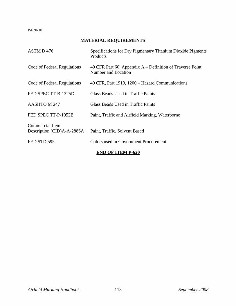
Airfield Marking Handbook September 2008 113
P-620-10 MATERIAL REQUIREMENTS
ASTM D 476 Specifications for Dry Pigmentary Titanium Dioxide Pigments
Products Code of Federal Regulations 40 CFR Part 60, Appendix A – Definition of Traverse Point
Number and Location Code of Federal Regulations 40 CFR, Part 1910, 1200 – Hazard Communications FED SPEC TT-B-1325D Glass Beads Used in Traffic Paints AASHTO M 247 Glass Beads Used in Traffic Paints FED SPEC TT-P-1952E Paint, Traffic and Airfield Marking, Waterborne Commercial Item Description (CID)A-A-2886A Paint, Traffic, Solvent Based FED STD 595 Colors used in Government Procurement
END OF ITEM P-620

Airfield Marking Handbook September 2008 114
APPENDIX B: Description of Standard Specifications STANDARD SPECIFICATIONS Civil (FAA or ICAO) Construction specifications for airfield markings are governed by the Federal Aviation Administration through the use of Advisory Circulars, Signs and Marking Supplements (SAMs), and occasionally via the local jurisdiction’s preferences due to experience and other considerations. [http://www.faa.gov/airports_airtraffic/airports/airport_safety/signs_marking/supplement/] FAA AC 150-5340-1J, published April 29, 2005 (Change 1 published 3/31/08) This document describes the different marking elements on a commercial or general aviation airport. Detailing the dimensions, placement, colors, function, and other criteria for the markings, this circular serves as a guide for both design engineers and airfield marking applicators. Most of the markings are mandatory for use on FAA-Part 139 Certificated airports, that receive AIP or PFC funding, as outlined in grant assurances. Some design changes are permitted under special conditions when approved by the local FAA Regional or Area District Office in the form of a written waiver. FAA AC 150-5370-10C, Part 2 (Item P-620) This guide specification provides instruction for the design engineer, the applicator, and inspection team as to the types of materials that can be used, coverage rates, straightness, and dimension tolerances, as well as equipment approved for use. MILITARY CONSTRUCTION SPECIFICATIONS There are efforts to adopt a single standard for all military installations to provide a uniform, standard marking system, both in design and installation. However, at the present time, criteria vary from one branch of the service to the other; and identifying the correct specifications for the owner is essential. U. S. Air Force is governed by several specifications: Engineering Technical Letter (ETL) 04-2 was implemented in February 2004 and is sponsored by the Air Force Civil Engineering Support Agency. Similar to FAA AC 150-5340-1J, the ETL describes the different marking elements, their size, color, function, and position on the airfield, among other criteria. The document is to be used by designers when developing plans for airfield markings on USAF installations. ETL 97-18–provides guidance to the designer in specifying the proper material requirements, testing and submittal requirements, surface preparation methods, equipment to be used, and application methods for USAF installations.

Airfield Marking Handbook September 2008 115
ETL 97-17–provides guidance to the designer in specifying the proper method for removing either rubber or paint or both from airfield surfaces, including compliance criteria. ETL 97-16–provides guidance to the designer in specifying application of airfield markings under low temperature conditions, specifically with the use of Methyl-Methacrylate. It was developed initially by the Air Force for application on expeditionary airfields in cold conditions. Air Force Instructions (AFI) 32-1042 dated 27 October 2005 provide specific guidance on changes that need to be implemented without reconstructing the entire ETL. Comments and other information also are made in the form of Engineering Briefs published and distributed to U.S. Air Force engineers throughout the system. UFC 3-260-01 prescribes dimensional and geometric layout criteria for safe standards for airfields, landing zones, heliports, helipads, related permanent facilities, as well as the navigational air space surrounding these facilities. Sponsored by the USAF and AFCESA, it serves all military facilities in establishing uniform standards for operation. The U. S. Navy uses several specifications to describe its airfield marking standards: UFGS 32 17 24.00 10–is a new Unified Facilities Guide Specification sponsored by the U.S. Navy to combine common practices of Navy, Air Force, and Army in identifying marking elements, dimension, and location of the markings on military installations. Similar in purpose to FAA AC 150/5340-1J and USAF ETL 04-2, this document provides guidance when designing airfield marking projects for military installations. UFGS 32 01 11.51–provides guidance to the design engineer in specifying the proper material requirements, testing and submittal requirements, surface preparation methods, and application methods for U.S. Navy installations. This document is similar to FAA AC 150/5370-10C and USAF ETL 97-18. The Navair Manual, sponsored by the U.S. Navy, provides guidance to the designer of marking standards specific to the Navy, (e.g., simulated carrier decks for fixed wing and rotary wing aircraft). The U.S,. Army uses USACE TM 5-823-4, which describes the different marking elements, dimensions and locations of the markings that are installed on U.S. Army airfields. Projects on U.S. Marine installations generally utilize the Unified Facilities Guide Specifications sponsored by the U.S. Navy and Army Corps of Engineers.

Airfield Marking Handbook September 2008 116
Threshold Bar
Threshold Markings
Larger threshold markings were removed, exposing clean pavement.
Picture courtesy of NASA
Threshold Bar
APPENDIX C: Airfield Marking Elements Runway Designation Numerals represent the “whole number nearest one-tenth of the magnetic azimuth when viewed from the direction of approach.” (FAA AC 150/5340-1J) In other words, the runway numbers represent degrees on a compass closest to the orientation of the line of travel. In the picture shown of Runway 36R, the letter “R” has been added indicating a parallel runway, because both runways have the same compass coordinates. In order to distinguish parallel runways, a letter is added to indicate a “right” (R), “left” (L), or “center” (C), layout on the airfield. Runway Centerline markings designate the center of the runway. The centerline bars are measured from both ends toward the center; any irregularity in measurement is absorbed in the center of the runway, where it will be less noticeable. Runway Threshold markings designate the beginning and end of the runway. The number of threshold marking bars depends on the width of the runway; as the width of the runway decreases, the outer bars are eliminated; as the width increases, outer bars are added. In the picture below, an old threshold marking configuration was removed, and the new pattern was installed. Even though the pavement is 300-feet wide, the owner wanted to restrict the usable runway pavement to 150-feet wide.
Runway Threshold Bar: Seen in the picture, “the threshold bar delineates the beginning of the runway that is available for landing when there is pavement aligned with the runway on the approach side of the threshold.” (FAA AC 150/5340-1J, page 6) All measurements for the aiming point and touchdown zone markings begin at the base of the threshold markings, not the threshold bar or edge of pavement.

Airfield Marking Handbook September 2008 117
The aiming point markings are conspicuous targets for pilots.
Picture courtesy of NASA
Touchdown Zone
Aiming Point
Markings
Picture courtesy of NASASide Stripes
delineate the area intended to be used as
the runway surface; more
often grass abuts the side
stripe that then serves to
differentiate runway from surrounding
terrain..
Picture courtesy of NASA
Runway Aiming Point markings serve as a visual aiming point for landing operations. These large rectangular blocks are very conspicuous to the pilot approaching a runway for landing. The width of these markings varies depending upon the width of the runway. Runway Touchdown Zone markings identify the touchdown zone for landing operations. Consisting of groups of one, two, and three rectangular bars symmetrically arranged about the runway centerline, they are used on precision-marked runways to provide distance information to the pilot, and they are spaced every 500 feet in the touchdown area. Runway Side Stripe markings provide a visual contrast between the runway and the surrounding terrain and delineate the width of the paved area that is intended to be used as a runway. The stripes meet the threshold bar, if one exists, or they extend to the base of the threshold markings if not.
Arrows and Arrowheads “are used to identify a displaced threshold area and are useful for centerline guidance for takeoffs and/or rollouts.” (FAA AC 150/5340-1J, page 7) They are used in permanently displaced thresholds in advance of the threshold bar, further highlighting the beginning of a runway. When the arrows and arrowheads are white in conjunction with a white side stripe, they denote that the surface can be used for takeoffs or rollouts; but the landing area is restricted to beyond the threshold bar. However, when the arrows are yellow, the pavement prior to the threshold is not available for takeoff or rollout. There are other uses of arrows and arrowheads that can be found in the FAA

Airfield Marking Handbook September 2008 118
AC 150/5340-1J, figures 6 and 8 (pages 25 and 27 of that document) that convey other information to pilots and surface operators. Chevrons identify pavement areas unusable for landing, takeoff, and taxiing. They are located on pavement areas that are aligned with and contiguous to the runway; they are yellow and generally non-reflective.
Demarcation Bar is a 3-foot wide, yellow bar that extends across the width of the blast pad, stop way, or taxiway. Located on the blast pad, stop way, or taxiway at the point of intersection with the runway, the marking delineates a runway with a displaced threshold that precedes the runway.
Taxiways:
Next is a brief description and picture of some of the elements found on taxiways per the FAA.
Holding Position Markings are positions on or at the movement area where the pilot or surface operator must to stop before getting clearance from Air Traffic Control (ATC) to proceed.
Holding Position Markings on Taxiways indicate where an aircraft is to stop before gaining clearance from Air Traffic Control (ATC) to cross or enter the runway. The FAA and other industry specialists have worked to improve the conspicuity of these markings by making them wider and enhancing them with black borders, in order to improve situational awareness and prevent runway incursions.
Intermediate Holding Position Marking is a “taxiway/taxiway” hold marking, designed to provide a place on a taxiway for a pilot to wait for another aircraft taxiing on an
What appear to be black chevrons were old ones, removed since they conflicted with the new layout. Ultraviolet light will soon fade the unexposed, black asphalt to gray.
Pictures courtesy of NASA

Airfield Marking Handbook September 2008 119
Twelve-inch taxiway centerline is painted over runway markings when it designates a SMGCS route.
Non-movement boundary line
intersecting taxiway. They are to be outlined in black on light colored pavements, and are 1-foot wide by 3-foot long dashes and spaces. The taxiway centerline should be spaced 6-12 inches from the intermediate holding position marking. Holding Position Markings on Runways are installed on a runway where an aircraft is to stop when the runway is normally used as a taxiway or used for Land and Hold Short Operations (LAHSO). They are the standard design and size of the holding position marking; however, they take precedence over any runway markings with which they intersect.
Non-Movement Boundary Line is the point at which a surface operator or pilot has specific authorization to enter the movement area of the airfield. Free movement is permitted without specific authorization or clearance from the ATC within the gate area, inside the boundary line. The movement area of the airfield is any area regulated by ATC. The non-movement area is not regulated by the ATC.
Taxiway centerlines are six- or twelve-inches wide and designate the center of the taxiway. Serving the pilot in maneuvering between the apron or gate area and the runway, the taxiway centerline is one of the most critical markings on an airfield. Outlined in black on light colored pavement, the maneuvering aid is quite conspicuous. The line is always yellow and is reflectorized for nighttime visibility. On airports with designated Surface Movement Guidance Control Systems (SMGCS) routes, the taxiway centerlines are twelve-inches wide and take precedence over runway markings.

Airfield Marking Handbook September 2008 120
• The sign with the black background and yellow lettering is a location sign.
• The red and white sign is a surface
painted holding position marking sign.
Taxiway side lines, if used, denote the edge of usable pavement on the taxiway. If solid, the line should not be crossed; if dashed, as along a parking apron, the line can be crossed. Dashed lines are permissive, solid lines are restrictive.
Surface Painted Signs are among other markings appearing on taxiways to augment vertical and lighted signs that are positioned along the taxiway edge. Surface painted signs aid the pilot and other drivers during low visibility conditions when the signs may be difficult to see, or when a taxiway exceeds certain widths; they can provide guidance information to an operator.
The arrow within the direction sign with the
yellow background and black lettering indicates the direction of Taxiway W8.
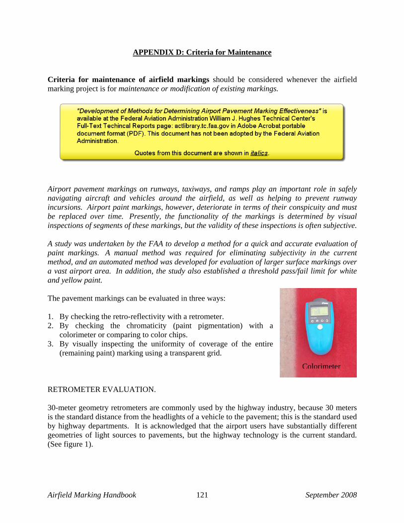
Airfield Marking Handbook September 2008 121
Colorimeter
APPENDIX D: Criteria for Maintenance Criteria for maintenance of airfield markings should be considered whenever the airfield marking project is for maintenance or modification of existing markings.
Airport pavement markings on runways, taxiways, and ramps play an important role in safely navigating aircraft and vehicles around the airfield, as well as helping to prevent runway incursions. Airport paint markings, however, deteriorate in terms of their conspicuity and must be replaced over time. Presently, the functionality of the markings is determined by visual inspections of segments of these markings, but the validity of these inspections is often subjective. A study was undertaken by the FAA to develop a method for a quick and accurate evaluation of paint markings. A manual method was required for eliminating subjectivity in the current method, and an automated method was developed for evaluation of larger surface markings over a vast airport area. In addition, the study also established a threshold pass/fail limit for white and yellow paint. The pavement markings can be evaluated in three ways: 1. By checking the retro-reflectivity with a retrometer. 2. By checking the chromaticity (paint pigmentation) with a
colorimeter or comparing to color chips. 3. By visually inspecting the uniformity of coverage of the entire
(remaining paint) marking using a transparent grid. RETROMETER EVALUATION. 30-meter geometry retrometers are commonly used by the highway industry, because 30 meters is the standard distance from the headlights of a vehicle to the pavement; this is the standard used by highway departments. It is acknowledged that the airport users have substantially different geometries of light sources to pavements, but the highway technology is the current standard. (See figure 1).

Airfield Marking Handbook September 2008 122
MANUAL METHOD
FIGURE 1 - Thirty-meter geometry measurement for retro-reflectivity evaluation. A retrometer is shown in the picture below and is measuring the retro-reflectivity of the white airfield marking. By establishing performance criteria that include target reflectivity values at installation, inspectors can record readings to ensure compliance. When this measure is used, nighttime visibility will be enhanced.
Although most airports might not invest in this equipment, many airport operators can detect substandard retro-reflectivity by observing airfield markings during a nighttime inspection. Uniform reflectivity of a marking is the goal, as seen in the picture to the right.
CHROMATICITY Measuring or comparing the color of markings to standards (maintained by all government agencies) will indicate if the marking pigments have degraded (i.e. faded, paled, etc.) The colorimeter pictured on the previous page provides coordinates that can be plotted on the grid shown as Figure A-1 and A-2 in the FAA report. Figure A-1 and A-2 show the color ranges that are acceptable for non-reflective and reflective markings respectively. Outside of that range is unacceptable. The use of color chips corresponding to the Federal standards can be used to
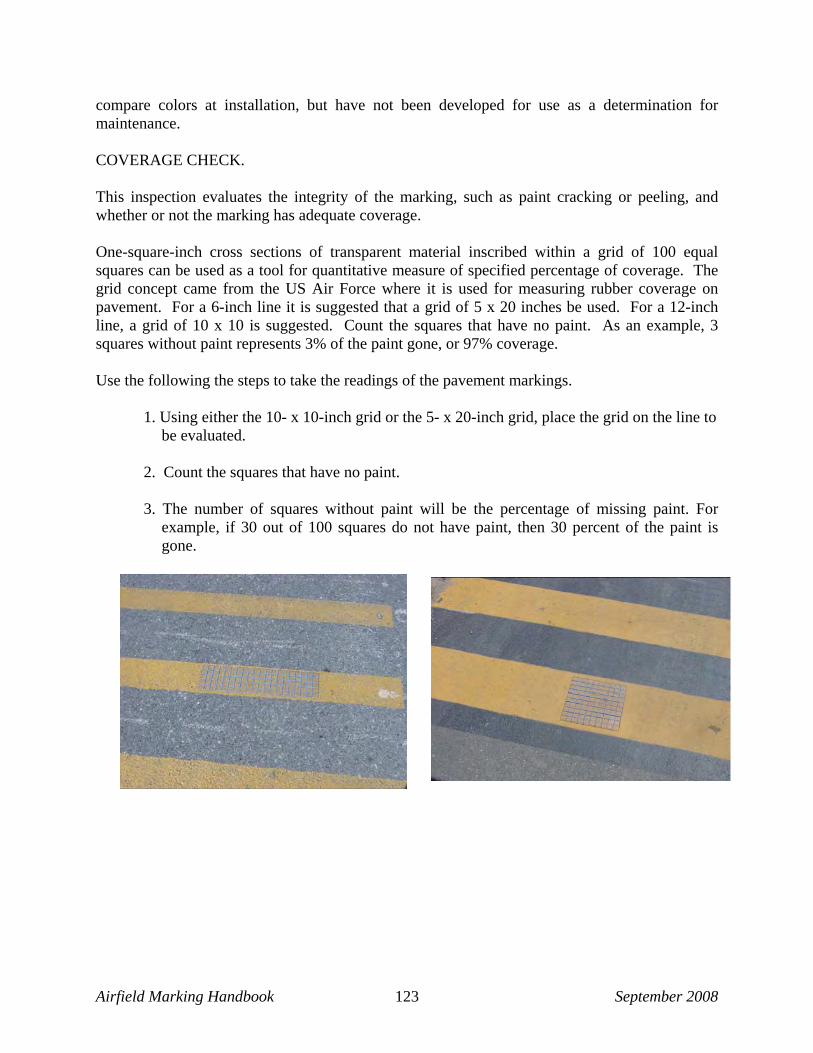
Airfield Marking Handbook September 2008 123
compare colors at installation, but have not been developed for use as a determination for maintenance. COVERAGE CHECK. This inspection evaluates the integrity of the marking, such as paint cracking or peeling, and whether or not the marking has adequate coverage. One-square-inch cross sections of transparent material inscribed within a grid of 100 equal squares can be used as a tool for quantitative measure of specified percentage of coverage. The grid concept came from the US Air Force where it is used for measuring rubber coverage on pavement. For a 6-inch line it is suggested that a grid of 5 x 20 inches be used. For a 12-inch line, a grid of 10 x 10 is suggested. Count the squares that have no paint. As an example, 3 squares without paint represents 3% of the paint gone, or 97% coverage. Use the following the steps to take the readings of the pavement markings. 1. Using either the 10- x 10-inch grid or the 5- x 20-inch grid, place the grid on the line to
be evaluated. 2. Count the squares that have no paint. 3. The number of squares without paint will be the percentage of missing paint. For
example, if 30 out of 100 squares do not have paint, then 30 percent of the paint is gone.

Airfield Marking Handbook September 2008 124
By using these three evaluations, one can determine whether or not the paint marking passes or fails. If the readings for any one of the three tests (the chromaticity, retro-reflectivity, or percentage of coverage) fail, the pavement marking automatically fails. AUTOMATED METHOD—VAN-MOUNTED RETRO-REFLECTIVE CHECK. The automated method for determining reflectivity values is faster, more advanced, and expensive; it requires little “downtime” on the airfield surfaces. However, the van-mounted retro-reflectometer has an accuracy of ±15 percent, whereas the manual retrometer has an accuracy of ±5 percent. The automated inspection system increases the speed and sample size. The automated inspection system has the following objectives:
• Evaluate entire painted marking configuration (i.e., inspection of the full length of runway centerline markings).
• Accomplish the evaluation within a limited timeframe (i.e., minimal runway downtime). • Take contrast of runway with adjacent surfaces (i.e., concrete, asphalt, or black paint)
into account. • Discriminate between reflective, beaded surfaces and non-reflective, non-beaded surfaces.

Airfield Marking Handbook September 2008 125
APPENDIX E: Checklists Checklist for Inspecting an Airfield Marking Project
� Provide an experienced inspection/quality control individual to monitor all aspects of the
airfield marking project. � Monitor surface preparation activities to ensure adequate cleaning of the surfaces to receive
new markings. � Calibrate equipment and/or have crew do test strips of the various activities. � Ensure all marking removal personnel are experienced in the operation of the equipment
being used. � Ensure that all environmental considerations have been addressed, that containment of
debris and other effluents is done. Check waste containment areas to insure compliance with local, state, and federal laws.
� Check all layout for proper alignment, position, and dimension of markings. � Check material upon delivery to the jobsite to ensure proper quantity and type. � Closely monitor material usage to ensure compliance with coverage rates.
Count initial material inventory. Compute quantity (square footage) of material applied. Divide square footage by amount (gallons) of paint (or other binder) applied. For
example, 11,500 square feet were applied; 100 gallons of paint were used; coverage rate was 115 square feet per gallon.
Divide amount of glass beads (pounds) applied by amount of paint (binder) applied. For example, assuming 700 pounds of Type I beads were used; 100 gallons of paint were used; coverage rate was 7 pounds of Type I glass beads per gallon.
� Periodically check wet film thickness of material being applied. � Periodically check for correct glass bead population, distribution and embedment. � Calculate quantity of markings applied and compare to amount of materials used. � Ensure that any paint removal or surface preparation process has left the surface clean and
free from FOD. If markings are being reapplied in the same location, make certain all debris and grit are removed from the scarred pavement before applying new markings.
� During marking operations, make certain good alignment is maintained.
Airfield Marking Handbook September 2008 126
� Require documentation of each day’s activities and recording the following. The daily reports should be assembled as a journal, supplemented with digital photos, and provided to the owner at the project end.
Quantity of work completed satisfactorily, Location of completed work, Amount of materials used, Personnel hours, Equipment used, and Any other details that should be noted. If there are any discrepancies or unsatisfactory work, those areas should be
noted and scheduled for rework. Weather conditions.

Airfield Marking Handbook September 2008 127
Checklist for Designing an Airfield Marking Project
Determine user agency and funding jurisdiction.
Visit the airfield to assess and evaluate the scope of work.
Identify markings that are being changed. Note conditions of markings to be removed. Note condition of pavement under markings to be removed. Determine percentage of removal based on situation. Take photographs of markings to be removed. Provide airport personnel as well as potential contractors with clear expectations of
results, noting that all marking removal causes some scarring of pavements. The definition of pavement damage should be defined.
Identify types of removal equipment to be specified, taking into account pavement conditions, thickness and types of material to be removed, and the time of year or environment the work will be done.
Identify composition of existing marking materials.
Determine quantity of markings to be repainted without removal.
Note condition of markings to be repainted (take pictures). • Check existing markings for surface contaminants:
o Algae growth o Oil substances o Dirt, grass o Curing compound o Rubber deposits o Rust deposits/discoloration
• Check the adhesion of the existing markings: o Note the number of layers of marking material. o Perform an adhesion test on representative areas to be repainted. o Determine the condition of the pavement under the markings. o Consider the environment and level of UV deterioration.
• Check for proper alignment of existing markings (if out of alignment, is removal required? If so, layout may also be required, and should be stated in the job description.)
• Check for proper position and dimension of markings. (If incorrect, is removal required? If so, layout may also be required, and should be stated in the job description.)
Determine quantity of markings requiring surface preparation, distinguishing between the
areas needing different types of preparation. Identify methods of surface preparation to be employed.

Airfield Marking Handbook September 2008 128
Establish total quantity of markings to be repainted:
Reflective and non-reflective markings. Different color quantities.
Select a marking material that is compatible with existing materials unless they are being
removed.
Select materials appropriate to the needs of the airport environment. Are the markings stained with rust contamination? Are the markings affected by algae growth? Are there night operations that would warrant the use of high index glass beads? Are there areas that may benefit from a durable marking material?
Determine the type of equipment to be used.
If there are short work windows, truck-mounted equipment capable of applying 3-foot wide markings is desirable to reduce the amount of time operations will be disturbed.
Automatic glass bead dispensers should be used to provide optimum embedment of glass beads to the marking and to enable calibration and correct coverage rates.
Schedule the work for a time of year, based on the environment, conducive to the application
of the selected materials.
Specify that materials should arrive in unopened containers, along with paperwork to match the batch numbers. (Equipment shall not be pre-loaded with materials.)
If layout will be required, provide a description and magnitude of what is expected.
Specify that the material be applied in accordance with manufacturer’s recommendations,
including coverage rates, temperatures, etc.; and state that equipment shall be calibrated and/or test strips shall be performed.
Specify that material shall be applied in a uniform manner with an even cross section of paint
and a uniform distribution of glass beads with proper embedment.
Specify all other requirements from the prevailing guidance literature pertinent to the project.