Procedure Design ConsideraWons - ICAO
46
Procedure Design Considera0ons 1 Lead Instructor: Walter.White@AirTraffic.Biz
-
Upload
khangminh22 -
Category
Documents
-
view
1 -
download
0
Transcript of Procedure Design ConsideraWons - ICAO

Learning Objec0ves
✈ By the end of this presenta0on you should understand: ✈ Procedure design considera0ons including: ✈ Path Terminators
✈ Waypoint Types
✈ Factors affec0ng turn radius
2

Assump0ons >> Design
3
✱ When agreeing on assump0ons, Airspace Design Team determines what’s available in terms of ..
Ø Air Traffic
Ø Runways Ø C Ø N Ø S Ø ATM System
✱ The Airspace Design Team should design its airspace based on realis'c assump0ons i.e. by relying on what does exist or what will exist at implementa0on date (rather than on what one would wish to exist).

Conceptual Design: What Next?
4

Procedure Design Considera0ons RNAV Path Types
5

6
Why PBN

Slide 7
PBN Route Using Waypoints
Waypoints

Path Terminators
8
Terminator Path
C A
D F I
M R
Altitude
Distance
DME distance
Next leg
Manual termination
Radial termination
Fix F
Constant DME arc
Course to
Direct Track Course from a fix to Holding pattern
Initial Constant radius
Track between
Heading to
C D
H
R
A
I
V T

Path Terminators
✈ Track to Fix -‐ TF ✈ Direct to Fix -‐ DF ✈ Course to Fix -‐ CF ✈ Fix to Al0tude -‐ FA ✈ Course to Al0tude -‐ CA ✈ Heading to Al0tude -‐ VA ✈ Radius to Fix -‐ RF ✈ Fix to Manual Termina0on – FM/VM
9

Track to Fix
10
TF Leg
A
B
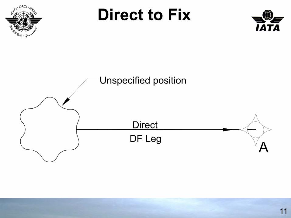
Direct to Fix
11
Direct DF Leg
Unspecified position
A

Course to Fix
12
CF Leg 080
A
0

Fix to Altitude
13
A Unspecified
Position
8000'
FA Leg
080 0

Course to Altitude
14
Unspecified Position
CA Leg 090 0

Unspecified Position
VA Leg 090 0
8000'
Heading to Altitude
15

Radius to Fix
16
Prev
ious
Se
gmen
t Arc Centre
A
C
B
RF Leg

Fix to Manual Termination
17
110° VM Leg
Radar Vectors

Track Distances Between Turns
18
Ya Yb
αa αb
Legdist
Fly-‐by WP
Fly-‐by WP
ra
r b
Ya
αa
Legdist
Fly-‐by WP
Fly-‐over WP
ra
αa
Legdist
Fly-‐over WP
ra1 Yb
αb
Fly-‐by WP
αa
Legdist
Fly-‐over WP
Fly-‐over WP ra1

19
Impact of Turn Performance Fly-‐By vs Fly-‐Over
Fly-By Fly-Over

Q2*t95-(43r/2)
20
Impact of Turn Performance Fly-‐By
DTA D
TA
MinimumSegment Length= DTA1+DTA2 X-y2/(-9/43z)
Q2*t95-(43r/2) J<>(t%w +(12#d-p4))
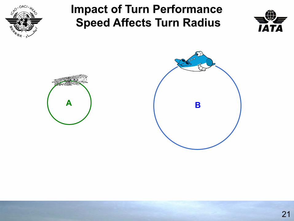
21
Impact of Turn Performance Speed Affects Turn Radius
A B

22
Impact of Turn Performance Bank Angle Affects Turn Radius
A B
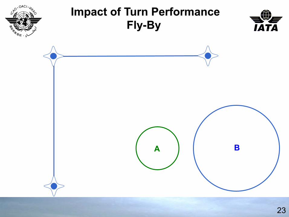
23
Impact of Turn Performance Fly-By
B A

24
Impact of Turn Performance
A
B
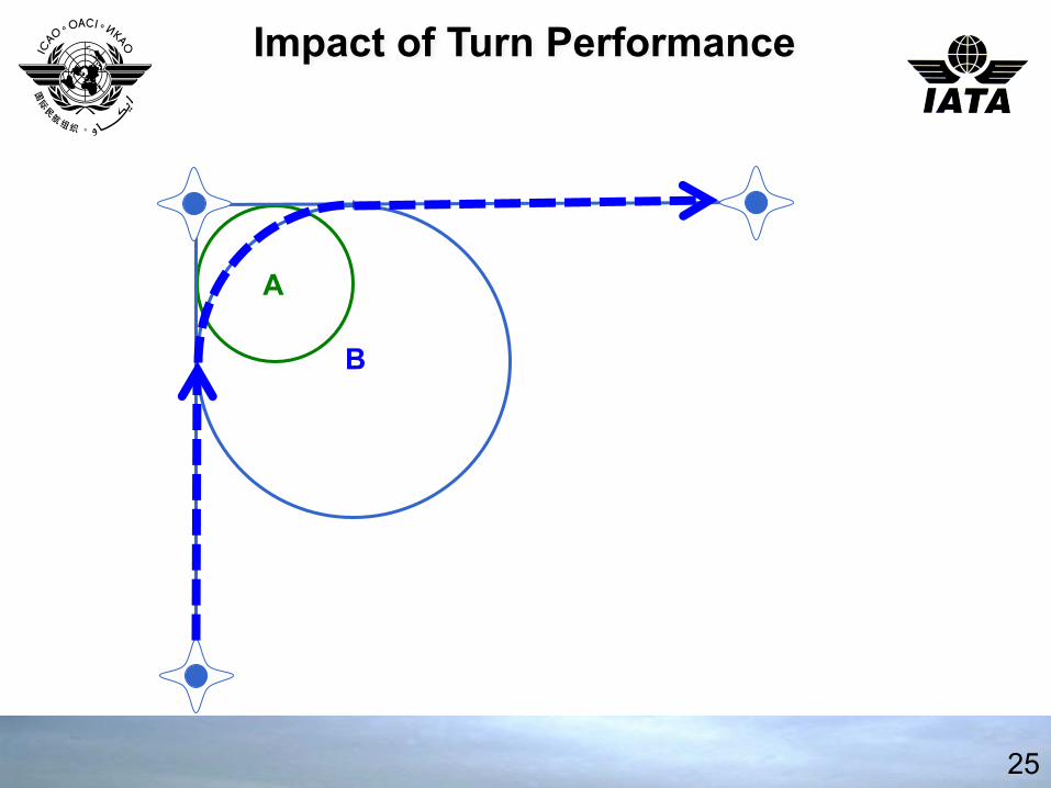
25
Impact of Turn Performance
A
B

26
Impact of Turn Performance
Turn Start Point ->
Turn Start Point ->

27
Impact of Turn Performance
A
B

28
Impact of Turn Performance
A
B

29
Impact of Turn Performance
A
B

30
Impact of Turn Angle

31
Impact of Turn Angle
A B

32
Impact of Turn Angle
A B
A B
33
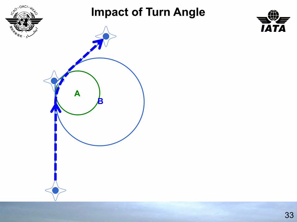
Impact of Turn Angle

34
Impact of Turn Angle
35
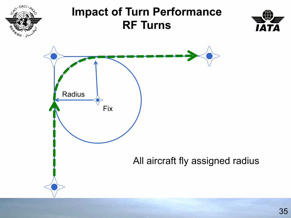
Impact of Turn Performance RF Turns
Fix
Radius
All aircraft fly assigned radius

ATC Design Considera0ons
✈ Turns of more than 90 degrees may result in significant track variaFon.
✈ Turns of 60 to 90 degrees create more manageable track variaFons.
✈ Turns of 60 or less result in liIle track variaFon.
✈ RF turns result in liIle track variaFon.
36

37
Impact of Turn Performance Controlling Angles & Speed

Speed and Al0tude Constraints
✈ Speed constraints allow Fghter turns and can assist ATC funcFon.
✈ AlFtude constraints can provide separaFon from obstacles and other aircraO.
38
Procedure Design Considera0ons
RNAV Approach Types
{ RNAV (GNSS) vs RNAV(RNP) }
39

PBN
40
ICAO State LeIer SP 65/4-‐13/24
Proposes amendments to: • PANS-‐OPS, Volume I • PAN-‐OPS Volume II • Annex 4 • Annex 6, Parts I, II and III • Annex 14, Volume II • Annex 15 • PANS-‐ABC
Applicable on 13 November 2014

RNAV (GNSS) Approaches
41
IAF
IAF IAF IF
FAF
MA pt
IF/IAF
FAF
MA pt
IAF IAF
T Bar Y Bar
70 o 90 o
FAF
With RF*
RF
MA pt
IAF
*PANS-OPS 2.4.1.4 13 NOV 2014
45 o
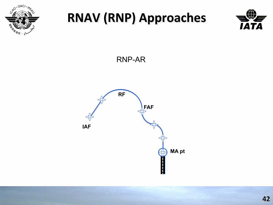
RNAV (RNP) Approaches
42
FAF
RNP-AR
RF
MA pt
IAF

RNAV (GNSS and RNP)
✈ RNAV(GNSS) is an RNP approach
✈ RNAV(RNP) is an RNP-‐AR approach
✈ LeIers in parenthesis are not said in clearance
✈ RNAV(GNSS) RWY22 and RNAV(RNP)RWY22 are both cleared as RNAV RWY22 approach.
43

RNAV (GNSS and RNP)
• State Letter SP 65/4-13/24 effective 13 NOV 2014 • A one-step eight-year transition period, starting 13 November 2014, is
being proposed to allow States sufficient time to develop a transition plan and to convert the existing RNAV approach procedures to RNP by 2022.
• ICAO will issue a new circular (Circ 336 — Circular on Conversion of RNAV to RNP Approach Chart Depiction)
• From 1 December 2022: • charts depicting procedures that meet the RNP APCH navigation
specification criteria shall include the term RNP in the identification (e.g. RNP RWY 23).
• charts depicting procedures that meet the RNP AR APCH navigation specification shall include the term RNP in the identification with a parenthetical suffix (AR). (e.g. RNP RWY 23 (AR)).
44

Reminder Steps so far!
✈ What is the Intended Purpose – as per Airspace Concept ✈ Which Operators and AircraO Types – as per traffic sample (assump3ons) ✈ What is the Navaid Coverage – as per infrastructure assump3ons ✈ What are the Environment Constraints – determined by Airspace Design Team ✈ What other Constraints, incl. obstacles? ✈ Design the Procedure
45

Thank You
46