1999_044.pdf - ISSMGE
7
INTERNATIONAL SOCIETY FOR SOIL MECHANICS AND GEOTECHNICAL ENGINEERING This paper was downloaded from the Online Library of the International Society for Soil Mechanics and Geotechnical Engineering (ISSMGE). The library is available here: https://www.issmge.org/publications/online-library This is an open-access database that archives thousands of papers published under the Auspices of the ISSMGE and maintained by the Innovation and Development Committee of ISSMGE.
-
Upload
khangminh22 -
Category
Documents
-
view
0 -
download
0
Transcript of 1999_044.pdf - ISSMGE

INTERNATIONAL SOCIETY FOR
SOIL MECHANICS AND
GEOTECHNICAL ENGINEERING
This paper was downloaded from the Online Library of the International Society for Soil Mechanics and Geotechnical Engineering (ISSMGE). The library is available here:
https://www.issmge.org/publications/online-library
This is an open-access database that archives thousands of papers published under the Auspices of the ISSMGE and maintained by the Innovation and Development Committee of ISSMGE.

Geotechnical Aspects of Underground Construction in Soft Ground, Kusakabe, Fujita & Miyazaki (eds)© 2000 Balkema, Rotterdam, ISBN 90 5809 1 066
The Westerschelde tunnel: New shield technologies in Europe
H.-J. S ager
Philipp Holzmann AG, Diisseldorjf Germany
M. HerrenknechtHerrenknecht AG, Schwanau, Germany
ABSTRACT: The ‘Westerschelde Tunnel’ underpasses the estuary of the Schelde in the Netherlands. Thetunnel will consist of two tubes which are driven by two hydroshields (slurryshields). The tunnels will eachhave a length of approx. 6.6 km and a bore-diameter of 11.33 m. Demanding ground conditions had to be considered during the design of the shield machines. Loose sands, extensive clay formations and high groundwater pressures of up to 6.5 bar will be encountered during the tunnel drive. As a result the shield machinesare among the rnost sophisticated tunnelling equipment available today. Further developments in Europeanshield technology include a Sonic Soft Ground Probing System with which a three-dimensional picture ofdiscontiuities ahead of the shield machine can be achieved.
1 INTRODUCTION
In 1996 a contract was signed with the KombinatieMiddelplaat Westerschelde Consortium (KMW) todesign and construct two tunnels which underpassthe Westerschelde in the south of the Netherlands as
well as the necessary infrastructure to operate the J ii iftunnel and to connect it to the existing road system. i H EThe consortium consists of six partners: BAM In- 1 _4Qfrabouw BV, Heijmans NV, Voormolen Bouw BV(all Dutch), Franki BV (Belgian), Philipp HolzmannAG and Wayss & Freytag AG (both German). Thetunnelling activities are scheduled to take place between the middle of l999 and the end of 2001.
The tunnels will then be equipped and should beready for operation in March 2003. The overall project value is 1.6 billion Dutch guilders (approximately S 850 million).
cable tunnel_filled soil .Figure l. Cross-section of the Westerschelde tunnel.
A prefabricated cable canal/duct Will be placedbeneath the road level. The cable canal/duct will
2 CROSS-SECTION
The Westerschelde tunnel consists of two tubes with
a length of 6.6 km, each will contain a two-laneroad. Figure l shows the cross-section of the tumrel.
The intemal tunnel diameter, including the associated clearance, will be l0.l0 m. A segment thicknessof 45 cm and a 16.5 cm layer of injected cementgrout (armular gap injection) results in an externalshield diameter of l 1.33 m. The segment width shallbe 2.0 m. The 53.000 segments needed for the tumiellining are manufactured in a segment plant that hasbeen specially constructed on site.
hold utilities that are needed for safety and for theoperation of the tunnel. Maintenance Work can becarried out by using specialised small vehicles whichare able to travel in the cable canal.
The two main tubes will be connected with 26
cross-passages that are spaced at 250 m.
3 GEOLOGICAL CONDITIONS
The geology along the tunnels is made up by different sand and clay formations. Figure 2 shows thegeology and a longitudinal section of the tunnel.
287

PAS VAN TERNEUZEN EVERINGEN 0QUAETANAR
ca. eeoo m ....,
YSAND V10m
10m
30m
40m
50m
6CIr’n
Figure 2. Geology and longitudinal section of the Westerschelde tunnel.
The uppermost 20 to 30 m consist mostly ofmeditun to fine grained sands. The sands on the northern side of the Westerschelde have an underlyinglayer of tertiary, glauconitic sands.
‘Boomse clays‘, overconsolidated stiff to firm tertiary clays are situated beneath the sands. These layers have a thickness of between 10 m to 30 m. The
‘Boomse clays’ are located at a greater depth in thenorth than in the south. According to their clay content and their mechanical properties the ‘Boomseclays’ can be divided into two layers: The ‘upperBoomse clay’ with an average clay traction of 60%and the ‘lower Boomse clay’ with a clay fraction ofroughly 40%.
Both clays can be expected to show sticky behaviour, demanding a consequent optimisation of excavation and handling of spoil material. The ‘lowerlayer of Boomse clay’ frequently shows sand bandswith a thickness varying from several decimetres upto 1,8 m.
Tertiary, glauconitic sands are found beneath the‘Boomse c1ays’. The perched groundwater table inthese sands corresponds with the sea level.
The Westerschelde has a width of approximately5500 m at the tunnel location. The tunnel drives de
scend from the south side at a gradient of 4.5% towards the deepest point of the tumiel, which is located at the ‘Strait of Terneuzen’. At this point thetunnel crown is up to 50 m and the estuary bed up to35 m below sea level. Depending on tidal changesthe necessary slurry pressure in the crown for thesupport of the turmel face will amount up to 6.5 bar.Thus the slurry pressure in the invert of the shield'sexcavation chambers will be up to 8 bar. Underpassing the Strait of Terneuzen is therefore considered to be one of the special technical challenges ofthis project.
Thereafter the turmel drive underpasses an extensive sand bank. After that the tunnel passes under thestrait of Everingen in a depth of 40 m below sealevel. Finally the tunnel ascends towards the receivershaft, passing through different sands.
288
4 TUNNEL BORING EQUIPMENT
The construction schedule allows for a period of nomore than 27 months for the tunnel drive. In order to
meet this tight schedule two slurry shields will beimplemented simultaneously, one for each tube. Dueto organisational reasons the second shield will startroughly 3 months after the first. A further consequence of the limited construction time is that allnecessary equipment for the construction of the fillbeneath the road has to be included on the backuptrain.
The high level of support pressure and the extensive clay formations had to be considered carefullyduring the design of the shield machines. Figure 3shows a section through the shield machine.
The fundamental decision of implementing eitherslurry shields, earth pressure balance shields or convertible machines (switching from slurry- to EPBmode) was decided in favour of the hydro shield(slurry shield). The hydro shield features a submerged wall with an opening at the bottom separating the excavation chamber from the work chamberwhere the suction inlet is located. The support pressure in the slurry is controlled with a bubble of compressed air in the upper half of the work chamber.The following main aspects had to be carefully analysed in the process of choosing the best suitableshield:
l. Controlling large ground water pressure2. Access to the excavation chamber under high
pressure by using divers3. Minimisation of wear
4. Consequent optimisation of the flow of materialat the cutterhead and in the excavation chamber
5. Optimisation of the logistical systems
e4. l Excavkztion
The open cutterhead, as seen in Fig. 4, has sixspokes with a peripheral rim. The shape of thespokes has been optimised to enhance the flow Of

Figure 3. Section through the shield machine for the Westerschelde tunnel. F VHIVHVIIIIIIVIWVA
I
Figure 4. Shield machine in the workshop.
excavated material. Two plows on the backside ofthe cutterhead will shove the spoil towards theopening of the submerged wall and the suction inlet.
The cutting plane of the excavation tools lies 200mm in front of the steel body of the spokes. Claychtmks that are cut during the tunnel drive are supposed to be isolated rapidly in the support fluid instead of adhering to each other and to the structureof the cutterhead. The material of the cutting tools,their geometry and their equipment with teeth ofhardened steel are designed to ensure lasting performance.
The centre of the main cutterhead is equipped witha separate centre cutter of 2.5 m diameter (see Fig.5). It is able to tum with or against the direction ofthe main cutterhead while rotating approximatelythree times as fast. The centre cutter is equippedwith its own slurry feeding system feeding freshsuspension and extracting the spoil loaded slurry. Itis also equipped with high pressure water jets forclearing clogged soil.
289
Figure 5. Detail of the centre cutter.
Behind the submerged wall in front of the suctioninlet a rotary cylinder crusher and two fast-runningagitators are installed (see Fig. 6). A crusher of thistype has been installed although it is unlikely thatlarge stones will be encountered along the givengeological situation. The advantages of the crusherare its ability to reduce large chips of firm clay tosmall pumpable pieces as well as its supporting action for the suction inlet because of its cylinderrotation.
The chosen combination of rotary crusher andagitators guarantees that slurry flow blockagescaused by static obstacles, as known from othertypes of crushers, will not occur. The strongturbulences created by the rotary crusher andagitators willrprevent spoil from settling in front ofthe suction inlet.
This means that less suspension has to be injectedthrough nozzles in front of the suction inlet in orderto create strong liquid jets to keep excavated spoilfrom settling.

2
Figure 6. Submerged wall opening with agitators,stone crushers and suction inlet.
A new concept for the distribution of the Eeshsuspension in the excavation and working chamberhas been developed. It has substantial improvementscompared to older hydro shields and enables the feedflow to be directed to numerous points in bothchambers:
l. the centre of the main cutterhead
2. the independent centre cutter3. the peripheral area and central area of the
excavation chamber
4. the area in front of the submerged wall opening5. the area in front of the suction inlet
In addition a recirculation pump is integrated inthe shield, drawing suspension nom the work chamber and re-injecting it at the top section of the excavation chamber. The overall circulation through thetwo chambers is thus increased by up to 30 %.
A large number of valves and pumps are requiredfor the above described multiple-inlet-feed in orderto control the suspension flow. The valves will beswitched in groups following a number of scenarioswhich have previously been programmed in order toallow the tbm operator to continously supervise allof them. The program will allow the operator to direct the feed flow in front or behind the submergedwall or to divide it between both areas in several
steps.
4.2 Maintenance under high pressure
The tunnel drive will incorporate long sectionswhere maintenance works under compressed air willnot be possible because of the high support pressuresand because of unacceptable chances of blowouts. Inthese sections the excavation chamber will beentered by off-shore divers. These men have beentrained to do maintenance on the cutterhead while
diving in the bentonite suspension. The requiredpersonnel from off-shore diving contractors will be
integrated in the ttumelling crews and therefore willalways be on site.
4.3 Machine data
The recorded and visualised data of the shield machines is supplemented by data that can be related tothe development of clay clogging in different areasof the shield. All relevant data will be monitored and
analysed regularly during the tunnelling process.This allows the detection of clogging at an earlystage where countermeasures can still be undertaken.
The cutterhead pressure and cutterhead torque aswell as the pressures in different areas of both chambers will be some of the available data that will bemonitored.
4.4 Tail skin seal
The seal of the shield tail consists of four rows ofwire brushes in order to cope with the high groundand water pressures. The four rows of brushes provide for three chambers to be filled with tail skinsealing compound. The pressure in the sealing compound is monitored directly along the circumferenceof all three chambers. Local irregularities, such asleakage’s in the wire brushes can thus be detected atan early stage.
4.5 Annular grout injection
Four double-piston pumps are used to inject groutthrough eight grout lines, in the tail skin, into theannular gap around the segment lining. lin the claysections of the tunnel the mortar could have difficul
ties to consolidate by dissipating filtrate water to thesurrounding ground due to the high impenneabilityof the clay. Therefore, a fast build-up of an effectivebedding of the tunnel might be impaired. Should thisbe the case, incompatible deformations of the segments rings could result. However the joint venturewill be able to use results of a research program, thatwas carried out by Philipp Holzmann AG and Herrenknecht GmbH, in order to prevent this.
In this program, large scale tests were conductedwith a new system that quickly improves the properties of the injected mortar. A large test rig was builtfor these tests, simulating a continuously developinggap of realistic dimensions that could be injectedunder pressures of up to 3 bar. An additive that enhances the stiffness within a few minutes is added to
the mortar just in front of the tail skin.
This isfan effective countermeasure against mortarflow within the annular gap, and therefore alsominimises tunnel displacements. The test rig made itpossible to visualise the spreading of the grout, inthe annular gap, through the injection of differentcoloured mortars. Further, valuable information were
290
to shield
from shield _ _dewotenng sieve
_ if 0.5mmcoarse sieve# 4mm 1 P
feed purf pump- _ 1 ._conveyer machinery conveyer machineryA L
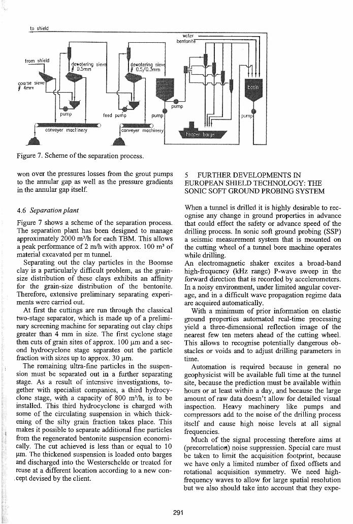
Figure 7. Scheme of the separation process.
won over the pressures losses from the grout pumpsto the annular gap as well as the pressure gradientsin the annular gap itself
4.6 Separation plant
Figure 7 shows a scheme of the separation process.The separation plant has been designed to manageapproximately 2000 m3/h for each TBM. This allowsa peak performance of 2 m/h with approx. 100 m3 ofmaterial excavated per m tunnel.
Separating out the clay particles in the Boomseclay is a particularly difficult problem, as the grainsize distribution of these clays exhibits an affinityfor the grain-size distribution of the bentonite.Therefore, extensive preliminary separating experiments were carried out.
At first the cuttings are run through the classicaltwo-stage separator, which is made up of a preliminary screening machine for separating out clay chipsgreater than 4 mm in size. The first cyclone stagethen cuts of grain sites of approx. 100 um and a second hydrocyclone stage separates out the particlefraction with sizes up to approx. 30 um.
The remaining ultra-fine particles in the suspension must be separated out in a further separatingstage. As a result of intensive investigations, together with specialist companies, a third hydrocyclone stage, with a capacity of 800 m3/h, is to beinstalled. This third hydrocyclone is charged withsome of the circulating suspension in which thickening of the silty grain fraction takes place. Thismakes it possible to separate additional fine particles
from the regenerated bentonite suspension economically. The cut achieved is less than or equal to 10um. The thickened suspension is loaded onto bargesand discharged into the Westerschelde or treated forreuse at a different location according to a new concept devised bythe client.
water ' .bentonite
""'\J""\~./
1 l_" T
5 FURTHER DEVELOPMENTS INEUROPEAN SHIELD TECHNOLOGY: THESONIC SOFT GROUND PROBING SYSTEM
Vlfhen a tunnel is drilled it is highly desirable to recognise any change in ground properties in advancethat could effect the safety or advance speed of thedrilling process. In sonic soft ground probing (SSP)a seismic measurement system that is mounted onthe cutting wheel of a trurnel bore machine operateswhile drilling.An electromagnetic shaker excites a broad-bandhigh-frequency (kHz range) P-wave sweep in theforward direction that is recorded by accelerometers.In a noisy environment, under limited angular coverage, and in a difficult wave propagation regime dataare acquired automatically.
With a minimum of prior information on elasticground properties automated real-time processingyield a three-dimensional reflection image of thenearest few ten meters ahead of the cutting wheel.This allows to recognise potentially dangerous obstacles or voids and to adjust drilling parameters intime.
Automation is required because in general nogeophysicist will be available full time at the tunnelsite, because the prediction must be available withinhours or at least within a day, and because the largeamount of raw data doesn’t allow for detailed visual
inspection. Heavy machinery like pumps andcompressors add to the noise of the drilling process
itself and cause high noise levels at all signalHequencies.
Much of the signal processing therefore aims at(precorrelation) noise suppression. Special care mustbe taken to limit the acquisition footprint, becausewe have only a limited number of fixed offsets androtational acquisition symmetry. We need highfrequency waves to allow for large spatial resolutionbut we also should take into account that they expe

transmitter
boulder receiver 1/ receiver 2
TBM steeringcabin
dun?
y /cutter signalwheel transferPlanar cables
discontinuity
recordingunit
Figure 8. Measurement principle Sonic Soft Grotmd Probing system (SSP).
Figure 9. Image of an injection block before andafter the simulation of the advance.
rience considerable attenuation in less consolidated
rock or ground. Since a large amount of data must beprocessed in real time efficient implementations areessential. Migration velocity field and other processing parameters are extracted automatically fromthe seismic data. An interactive graphics tool assists
the civil engineers in the interpretation of the final 3D model. Figure 2 shows the final reflection imageof an injection body before (lower) and after simulation ofthe advance (upper).
Sonic soft ground probing (SSP) is a novel seismic system that is mounted on the cutting wheel of atunnel bore machine and records seismic energy excited by a high-frequency electromagnetic vibroseisshaker. Unfavourable conditions imply on the one
292
hand the need for powerful processing tools and onthe other hand call for simple and robust methods.Acquisition and processing are fully automated andyield a 3-D image of reflection energy ahead of thetunnel face in real time.
The SSP system has been developed in cooperation by Amberg Messtechnik AG (Switzerland),Herrenknecht AG, Philipp Holzmann AG and ZtiblinAG (all from Germany).
6 CLOSING REMARK
The technical standard of shield tunnelling equipment has made some remarkable progress with thelast several years. This progress has been boosted bysuch challenging tunnel project such as the Westerschelde tunnel.
Building the Westerschelde tunnel is an extraordinary assignment for of those involved in the projectand is setting new standards as for mastering geotechnical challenges.