Moment–rotation–temperature curves for semi-rigid joints
23
Journal of Constructional Steel Research 61 (2005) 281–303 www.elsevier.com/locate/jcsr Moment–rotation–temperature curves for semi-rigid joints K.S. Al-Jabri a,∗ , I.W. Burgess b , T. Lennon c , R.J. Plank d a Department of Civil and Architectural Engineering, College of Engineering, Sultan Qaboos University, P.O. Box 33, 123 Al Khod, Oman b Department of Civil and Structural Engineering, University of Sheffield, Sheffield, UK c Building Research Establishment Ltd, Watford, UK d Department of Architectural Studies, University of Sheffield, Sheffield, UK Received 20 July 2004; accepted 23 September 2004 Abstract Although connections are known to have a very significant effect on the behaviour of steel and composite framed buildings in the event of fire, the cost of high temperature tests on the broad range of connections used in practice means that their influence is not well detailed in current design codes. The paucity of data also limits the effective use of numerical models developed to simulate the behaviour of complete structures at elevated temperature. This research describes a series of elevated temperature tests conducted on beam-to-column connections. This paper presents moment–rotation–temperature curves for a variety of connections. © 2004 Elsevier Ltd. All rights reserved. Keywords: Bare-steel; Composite; Connections; Joints; Elevated-temperature; Moment–rotation curves; Fire 1. Introduction Traditionally the design of steel framed structures assumes that the actual behaviour between the beam and the column is either rigid (implying complete rotational continuity) ∗ Corresponding author. Tel.: +968 24415 335; fax: +968 24413 416. E-mail address: [email protected] (K.S. Al-Jabri). 0143-974X/$ - see front matter © 2004 Elsevier Ltd. All rights reserved. doi:10.1016/j.jcsr.2004.09.001
-
Upload
independent -
Category
Documents
-
view
0 -
download
0
Transcript of Moment–rotation–temperature curves for semi-rigid joints

Journal of Constructional Steel Research 61 (2005) 281–303
www.elsevier.com/locate/jcsr
Moment–rotation–temperature curves forsemi-rigid joints
K.S. Al-Jabria,∗, I.W. Burgessb, T. Lennonc, R.J. Plankd
aDepartment of Civil and Architectural Engineering, College of Engineering, Sultan Qaboos University,P.O. Box 33, 123 Al Khod, Oman
bDepartment of Civil and Structural Engineering, University of Sheffield, Sheffield, UKcBuilding Research Establishment Ltd, Watford, UK
dDepartment of Architectural Studies, University of Sheffield, Sheffield, UK
Received 20 July 2004; accepted 23 September 2004
Abstract
Although connections are known to have a very significant effect on the behaviour of steel andcomposite framed buildings in the event of fire, the cost of high temperature tests on the broadrange of connections used in practice means that their influence is not well detailed in currentdesign codes. The paucity of data also limits the effective use of numerical models developed tosimulate the behaviour of complete structures at elevated temperature. This research describes aseries of elevated temperature tests conducted on beam-to-column connections. This paper presentsmoment–rotation–temperature curves for a variety of connections.© 2004 Elsevier Ltd. All rights reserved.
Keywords: Bare-steel; Composite; Connections; Joints; Elevated-temperature; Moment–rotation curves; Fire
1. Introduction
Traditionally the design of steel framed structures assumes that the actual behaviourbetween the beam and the column is either rigid (implying complete rotational continuity)
∗ Corresponding author. Tel.: +968 24415 335; fax: +968 24413 416.E-mail address: [email protected] (K.S. Al-Jabri).
0143-974X/$ - see front matter © 2004 Elsevier Ltd. All rights reserved.doi:10.1016/j.jcsr.2004.09.001

282 K.S. Al-Jabri et al. / Journal of Constructional Steel Research 61 (2005) 281–303
Nomenclature
L distance from the connection centreline to thepoint where deflection isdetermined.
u deflection of the point along the beam
M level of moment
A temperature dependentparameter representing connection’s stiffness
B temperature dependentparameter representing connection’s strength
n temperature dependent parameter defining curve sharpness
M1 moment corresponding withφ1
A1 temperature dependent constants for stage two of response representingconnection’s stiffness
B1 temperature dependent constants for stage two of response representingconnection’s strength
n1 temperature dependent constants for stage two of response defining curvesharpness
φ connection’s rotation
φ1 rotation at which the beam flange comes into with the column
or pinned [1]. However actual connection behaviourexhibits characteristics over a widespectrum between these two limits; connectionsregarded as pinned generally possess somerotational stiffness whilst rigid connections display some flexibility. Design procedures for‘semi-rigid’ frames have been developed but to simplify both design and construction,steel beams in multi-storey buildings are normally considered as simply supported with notransfer of moment to the columns. However, observations from fire damaged structures [2]and the fire tests on the Cardington full-scale frame [3] have demonstrated that even simpleconnections can resist significant moments, albeit at large deformations. This improves thesurvival time of the structure.
The traditional method for fire protecting structural steelwork is to use a suitableapplied protection material. However this can increase the overall cost of the structure byup to 30% [4], and extend the time for construction, offsetting some of the advantagesassociated with steel-framed construction. In order to minimise reliance on protectionmaterials there has been increased interest in developing a fundamental understanding ofstructural behaviour under fire conditions, considering memberseither in isolation or as apart of a more complete structure. Some research has focused on studying the influence oftemperature on the connection response. Most recent work has shown the importance ofmodelling appropriate structural assemblies – beams, columns and slabs – rather than justisolated members. If this is done properly the characteristics of the connections need alsoto be included, but this has been hampered by a lack of experimental data on the behaviourof steel and composite connections in fire.

K.S. Al-Jabri et al. / Journal of Constructional Steel Research 61 (2005) 281–303 283
Table 1Summary of experimental tests conducted on connections
Reference Connectiontype
Beam size Column size Bolt size &number
End-platethickness(mm)
Orientation &arrangement
(2) extendedbare
305×165×40UB (S275)
203×203×52UC (S275)
6 M20 12 Majorbeam–column
(2) flush bare 305×165×40UB (S275)
203×203×52UC (S275)
6 M20 12 Majorbeam–column
(1) webcleatbare
305×165×40UB (S275)
203×203×52UC (S275)
6 M20 12 Majorbeam–column
(1) flush bare 305×165×40UB (S275)
203×203×52UC (S275)
6 M20 12 Minorbeam–column
Lawson [7] (1) flushbare 305×165×40UB (S275)
6 M20 12 Minorbeam–beam
(1) webcleatbare
305×165×40UB (S275)
6 M20 12 Minorbeam–beam
(1) flushcomposite
305×165×40UB (S275)
203×203×52UC (S275)
6 M20 12 Majorbeam–column
(1) webcleatcomposite
305×165×40UB (S275)
203×203×52UC (S275)
6 M20 12 Majorbeam–column
(1) flushcomposite
305×165×40UB (S275)
6 M20 12 Minorbeam–beam
Leston-Jones [8] (5) flushbare 254×102×22UB (S275)
152×152×23UC (S275)
6 M16 12 Majorbeam–column
(2) flushcomposite
254×102×22UB (S275)
152×152×23UC (S275)
6 M16 12 Majorbeam–column
(*)—number of tests conducted.
A number of fire tests on connections were conducted by CTICM [5] in 1976 withthe primary purpose of investigating the performance of high strength bolts at elevatedtemperatures, and British Steel [6] carried out two indicative tests in 1982 on a momentresisting connection. Tests to study the behaviour of beam-to-column connections atelevated temperatures have been carried out by Lawson [7] and Leston-Jones [8]. Theseprovided useful data, but for a limited range of details, using relatively small section sizes.Table 1summarises some of the experimental tests conducted on connections at elevatedtemperature.
The aim of the work described here was to provide moment–rotation–temperature datafor a variety of practical shear-resisting connections. This was achieved through a seriesof tests conducted on a variety of full-scale beam-to-column connections using a portablefurnace. Both flush end-plate and flexible end-plate connections were studied.
2. Test arrangement and instrumentation
In all cases the test specimens consisted of a symmetric cruciform arrangement of a sin-gle column 2.7 m high with two cantilever beams 1.9 m long connected either side to the

284 K.S. Al-Jabri et al. / Journal of Constructional Steel Research 61 (2005) 281–303
Fig. 1. Elevated temperature testing arrangement.
column flanges as shown inFig. 1. All specimens were major axis connections i.e. beamsconnected to the column flanges with mild steel end-plates in Grade S275. All bolts weretightened to160 N m by a torque wrench to ensure consistency. The cruciform test ar-rangement requires a less extensive test rigthan the corresponding cantilever arrangement.It also provides an indication of the variability of the nominally identical connections oneither side of the column. Tests were performed in a gas-fired portable furnace lined withceramic fibre specially designed for testing connections. A linear temperature ramp (at arate of about 10◦C per minute) achieving 900◦C in 90 min was adopted.
The instrumentation included clinometers formeasuring rotations, displacement trans-ducers, load cells and thermocouples. Both analogue and digital output devices were mon-itored through an Orion Delta data logger. A full description of the instrumentation posi-tions, testing procedure and failure mode of the connections can be found elsewhere [9,10].
3. Connection details
In total twenty tests were conducted on five different connection details. The test groupsare described below:
Group 1 (FB1) The test specimens in this group comprised two 254× 102UB22 beamsconnected to a 152× 152UC23 column by 8 mm thick flush end-plates, with sixM16 Grade 8.8 bolts as shown inFig. 2. Four tests were conducted at load levelscorresponding to connection moments of 4 kN m, 8 kN m, 13 kN m and 17 kN m,which represent0.2, 0.4, 0.6 and 0.8 of the calculated moment capacity of theconnection(Mcc) as shown inTable 2.

K.S. Al-Jabri et al. / Journal of Constructional Steel Research 61 (2005) 281–303 285
Fig. 2. Group 1 (FB1) connection detail.
Group 2 (FB2) The test specimens in this group comprised a pair of 356× 171UB51beams connected to a 254× 254UC89 column by 10 mm thick flush end-plateswith eight M20 Grade 8.8 bolts (Fig. 3). This detail was adopted to study theinfluence of member size on the high temperature connection behaviour. Thecalculated moment capacity ofthis connection was140 kN m.Table 2shows thelevel of loading for each test in this group.
Group 3 (FLB3) The test specimens in this group comprised a pair of 356× 171UB51beams connected to a 254× 254UC89 column by 8 mm thick flexible end-plateswith eight M20 Grade 8.8 bolts (Fig. 4). This detail was chosen as typical ofthe connections used in the Cardington full-scale test frame. Load levels werebased on the connection response observed by Boreman et al. [11] as presented inTable 2.
Group 4 (FLC4) The composite connection shown inFig. 5 was the sameas Group 3.Five tests were conducted under this Group: one at ambient temperature and fourat elevated temperature as shown inTable 2.
Group 5 (FLC5) Fig. 6 shows thedetail of Group 5 composite connection in which610× 229UB101(Grade S275) beams were connected to a 305× 305UC137(Grade 355) column by 10 mm thick flexible end-plates with fourteen M20Grade 8.8. In total four tests were tested: one at ambient temperature and threeelevated temperature tests. Levels of loading for different tests were based on theexperimental ambient temperature connections test as presented inTable 2.
The form of the composite slab was a PMF COMFLOR C70 decking with 130 mmoverall slab depth using lightweight concrete of Grade C35 with A142 mesh reinforcement.

286 K.S. Al-Jabri et al. / Journal of Constructional Steel Research 61 (2005) 281–303
Table 2Level of loading for connection tests
Test Moment(M) Applied M Average recordedM Commentslevel (kN m) (kN m)
Group 1 FB11 0.2Mcc 4 4.40 Group 1, Test 1FB12 0.4Mcc 8 8.20 Group 1, Test 2FB13 0.6Mcc 13 13.12 Group 1, Test 3FB14 0.8Mcc 17 17.10 Group 1, Test 4
Group 2 FB21 0.2Mcc 27 27.4 Group 2, Test 1FB22 0.4Mcc 56 54.8 Group 2, Test 2FB23 0.6Mcc 82 82.1 Group 2, Test 3FB24 0.8Mcc 110 110 Group 2, Test 4
Group 3 FLB31 0.1Mcc 8 8.2 Group 3, Test 1FLB32 0.2Mcc 16 16.5 Group 3, Test 2FLB33 0.5Mcc 40 41.1 Group 3, Test 3
Group 4 FLC4AMB 1.0Mcc Full range 101.6 Ambient temperatureFLC41 0.32Mcc 34 34.3 Group 4, Test 1FLC42 0.46Mcc 46 47.5 Group 4, Test 2FLC43 0.59Mcc 62 61.4 Group 4, Test 3FLC44 0.78Mcc 82 82 Group 4, Test 4
Group 5 FLC5AMB 1.0Mcc Full range 101.6 Ambient temperatureFLC51 0.27Mcc 47 47 Group 5, Test 1FLC52 0.46Mcc 80 80.7 Group 5, Test 2FLC53 0.77Mcc 134 133 Group 5, Test 3
Mcc = Momentcapacity of the connection.
Slab dimensions were restricted due to the confinement of working within the furnace.The length of continuous slab across the connection was 1400 mm and its width was1200 mm. The length of the slab was enough to allow two 100 mm by 19 mm shear studs at300mm centres on each cantilever beam. Insulation material was attached to the top of theconcrete slab in order to prevent it from beingheated on this surface,thereby simulatingthe condition in a real fire.
For all specimens, ambient-temperature material properties were measured usingstandard tensile coupon tests and cross-sectional dimensions were recorded prior to testingin the furnace. Results are summarised inTable 3. The characteristic strength of theconcrete used in the construction of the composite slab at 28 days was designed tobe 35 N/mm2 with a workability correspondingto a slump of 75 mm. The averagecompressive concrete strength was 54.8 N/mm2 considerably higher than specified. Thecross-sectional area of the reinforcing mesh was consistent with the nominal value, withan area of approximately 28.82 mm2. However the yield strength of the reinforcement wasfound to be 6% greater than the nominal value. A summary of the mechanical propertiesfor the reinforcement and concrete are detailed elsewhere [12].
One of the main characteristics of some types of flexible end-plate joints is that theresponse has two stages: stage one: the unobstructed rotation of the connection and stagetwo: the beam lower flange bears against the column with further rotation. Therefore,during the testing of flexible end-plate connections (i.e. Groups 3 and 4) there was

K.S. Al-Jabri et al. / Journal of Constructional Steel Research 61 (2005) 281–303 287
Fig. 3. Group 2 (FB2) connection detail.
Table 3Material properties of steel sections used in the tests
Material Ultimate stress(N/mm2) Yield stress(N/mm2) Modulus of elasticity(kN/mm2)
S275 454 322 197S355 545 412 195
a problem of large rotation at low moments which prevented testing the specimen upto failure. This was because the specimen beams came into contact with the furnacedoors. For low load levels it was not possible to test the specimen to failure, and thetests were terminated when both the beams rested on the furnace doors. To resolve thisproblem for high load levels the specimen was initially loaded to the desired level atambient temperature. The loads were removed, and the furnace and instrumentation werereadjusted. The specimen was re-loaded to therequired level and the elevated temperaturetest started. This method allowed the specimen to be tested up to failure, over a completerotation range. Therefore the connection is assumed failed when either:
• Both beams rest on the furnace doors, or
• The connection is unable to sustain the applied load level due to failure of one or moreelements of the connection

288 K.S. Al-Jabri et al. / Journal of Constructional Steel Research 61 (2005) 281–303
Fig. 4. Group 3 (FLB3) connection detail.
Fig. 5. Group 4 (FLC4) connection detail.
Unlike ambient-temperature connection tests where a single test is sufficient todetermine the moment–rotation characteristics, a series of tests has to be conducted in order

K.S. Al-Jabri et al. / Journal of Constructional Steel Research 61 (2005) 281–303 289
Fig. 6. Group 5 (FLC5) connection detail.
to establish the corresponding relationships for elevated temperature. As a direct resultof such tests a family of moment–rotation curves at elevated temperatures for differentconnections may be generated. For this purpose, the connection tests were conducted bykeeping the specimen at a constant load level and increasing the furnace temperature untilfailure. This method has been shown to provide reliable results and yield adequate dataregarding the temperature distribution across the connection depth. Moreover, adopting aconstant load with increasing temperature regime reflects the situation in real building fires.Since the scope of the programme was restricted by the resources available and the numberof tests required to establish the elevated-temperature connection characteristics, it wasnotpossible to conduct ambient-temperature tests for bare-steel connections.
4. Temperature distribution across the connections
Temperature distribution across the depth of bare-steel and composite connectionsis shown inTables 4and 5 respectively. The temperature distribution is presented innon-dimensional form with respect to the exposed beam bottom flange temperature (thereference for the data logging). The average relative temperature profile was determinedbased on the average thermocouple readings of connection elements for the East andWestsides, after ensuring that the readings are consistent. Then, the relative temperatureprofile for each element is obtained by dividing the element temperatures by the referencetemperature (beam bottom flange). It may be seen fromFig. 4 that there is a uniformtemperature distribution across the depth of all bare-steel connections with no appreciabledifference in the temperature of the connection elements. The only exception was the

290K
.S.Al-Jabrietal./Journal
ofConstructional
SteelR
esearch61
(2005)281–303
Table 4Average relative temperature profile for bare-steels connections
TestGroup 1 tests Group 2 tests Group 3 tests
Element FB11 FB12 FB13 FB14 Av.b FB21 FB22 FB23 FB24 Av.b FLB31 FLB32 FLB33 Av.b
Beam bottom flange 1.00 1.00 1.00 1.00 1.00 1.00 1.00 1.00 1.00 1.00 1.00 1.00 1.00 1.00Beam web 1.04 1.03 1.06 1.10 1.06 1.06 1.04 1.10 1.02 1.06 1.10 1.03 1.04 1.06Beam top flange 1.02 1.02 1.02 1.01 1.02 1.03 1.00 1.01 1.02 1.02 1.04 1.04 1.01 1.03Beam top flangea 0.43 0.37 0.35 0.37 0.38 0.47 0.38 0.36 0.43 0.41 0.41 0.37 0.43 0.40Beam bottom flangea 0.39 0.37 0.40 0.37 0.38 0.45 0.37 0.36 0.42 0.40 0.41 0.37 0.41 0.40Top bolt 1.04 1.01 1.07 1.05 1.04 1.06 0.97 1.04 0.99 1.02 1.02 0.93 0.93 0.962nd row bolts 1.02 1.01 1.03 1.05 1.03 1.03 0.96 1.05 0.96 1.00 1.03 0.93 0.96 0.973rd row bolts N/A N/A N/A N/A N/A 1.08 0.97 1.04 0.95 1.01 1.01 0.92 0.95 0.96Bottom bolt 1.02 0.98 1.01 1.02 1.01 0.97 0.94 0.97 0.91 0.95 0.97 0.93 0.95 0.95Column web 1.10 1.14 1.14 1.16 1.14 1.15 1.20 1.27 1.23 1.21 1.20 1.08 1.08 1.12Column flange 1.00 1.03 1.04 1.03 1.03 0.90 0.97 1.00 1.03 0.98 1.01 0.94 0.93 0.96Column flangea 0.52 0.47 0.44 0.43 0.47 0.38 0.34 0.36 0.37 0.36 0.38 0.31 0.33 0.34End-plate 1.03 1.00 1.04 1.03 1.03 1.00 0.99 1.01 0.99 1.00 1.02 0.91 0.94 0.96Clinometer – 0.09 0.10 0.10 0.10 0.11 0.09 0.09 0.14 0.11 0.11 0.13 0.10 0.11Furnace atmosphere – 1.43 1.37 1.35 1.38 1.64 1.61 1.68 1.71 1.66 1.55 1.64 1.69 1.62
aIdentifies insulated thermocouple locations.bAverage temperature distribution.

K.S. Al-Jabri et al. / Journal of Constructional Steel Research 61 (2005) 281–303 291
Table 5Average relative temperature profile for composite connections
TestGroup 4 tests Group 5 tests
Element FLC41 FLC42 FLC43 FLC44 Av.b FLC51 FLC52 FLC53 Av.b
Beam bottom flange 1.00 1.00 1.00 1.00 1.00 1.00 1.00 1.00 1.00Beam web 1.01 1.04 1.09 0.99 1.03 1.11 1.06 1.15 1.11Beam top flange 0.58 0.72 0.70 0.72 0.68 0.84 0.82 0.77 0.81Beam bottom flangea 0.39 0.44 0.33 0.44 0.40 0.62 0.78 0.44 0.61Topbolt 0.72 0.83 0.77 0.75 0.77 0.93 0.89 0.94 0.922nd row bolts 0.86 0.87 0.91 0.84 0.87 – – – –Middle bolts – – – – – 1.01 0.95 1.03 1.003rd row bolts 0.85 0.88 0.94 0.88 0.89 – – – –Bottom bolt 0.92 0.92 0.92 0.91 0.92 1.00 0.99 1.01 1.00Column web 1.07 1.06 1.14 1.06 1.08 1.20 1.20 1.38 1.26Column flange 0.93 0.98 1.07 0.94 0.98 1.25 0.90 0.97 1.04Column flangea 0.33 0.35 0.40 0.37 0.36 0.39 0.26 0.29 0.31End-plate 0.98 0.86 0.89 0.85 0.90 1.00 0.95 1.03 0.99Concrete surface 0.09 0.14 0.13 0.17 0.13 0.18 0.13 0.13 0.15Clinometer box 0.08 0.09 0.09 0.11 0.09 N/A N/A N/A N/AFurnace atmosphere 1.35 1.35 1.59 1.58 1.47 1.63 1.67 N/A 1.65
aIdentifies insulated thermocouple locations.bAverage temperature distribution.
column web where the temperature difference in some tests reached up to 23% higherthan the reference temperature.
Table 5shows the average temperature profile across the composite connections, withthe beam bottom flangebeing chosen as the reference. It may be seen that there wassome degree of variation in temperature distribution across the depth of the connection,especially at the beam top flange due to the presence of the composite slab. The presenceof the composite slab above the connection caused a reduction of 19%–30% in the beam topflange temperature in both connections. This is due to the insulation and heat sink effect ofthe concrete slab and enhances the connection performanceat elevated temperatures. Onceagain, the highest temperature—about 8% and 26% higher than the beam lower flangetemperature—in the connection components was observed to be in the column web. Thetemperature maintained by the top surface of the concrete slab was approximately 13%and 15% of the beam lower flange temperature due to the protection of the fibre blanketfor Groups 4 and 5 respectively.
5. Measurements of connection’s rotation
Two devices: clinometers and displacement transducers were used to measure therotation of connections on either side of the arrangement (designated by East and Westconnections). The displacement transducers were basically used to measure the verticaldeflection at different locations along the beam. However, they can also be used as anindirect way to calculate the connection’s rotation. The connection’s rotation,φ, based

292 K.S. Al-Jabri et al. / Journal of Constructional Steel Research 61 (2005) 281–303
Fig. 7. Rotation of the connection.
on displacement transducer readings, canbe calculated from the following equation(Fig. 7):
φ = tan−1(u/L) (1)
where,u: deflection of the point along the beam;L: distance from the connection centreline to the point where deflection is determined.
In almost all the tests there was a good agreement between rotations recorded byclinometers and calculated from the displacement transducer readings for both the East andWest connections. This agreement is clearly shown inFig. 8(a) and (b) for test FB24 basedon clinometers and displacement transducers respectively. Also, the average rotationsof the connection based on clinometers anddisplacement transducers are compared inFig. 9(a) and (b) for tests FB13 and FLB33 respectively. It may be seen that there wasclose correlation between rotations recordedby clinometers and displacement transducerreadings, confirming the reliability of both devices in describing the connection response.Therefore, rotations calculated based on the displacement transducers were adopted in thetests where clinometers burned during some tests.
6. Temperature–rotation response of connections
It is possible to derive moment–rotation curves of connection at increasing temperature,by defining the temperature–rotation response of that connection at a number of load levels.The temperature–rotation response of connections generated from fire tests at differentlevels of loading is shown inFigs. 10–12 for bare-steel connections in Groups 1, 2 and 3respectively. It may be seen that the temperature–rotation curves of the connections are

K.S. Al-Jabri et al. / Journal of Constructional Steel Research 61 (2005) 281–303 293
(a) Clinometer response. (b) Displacement response.
Fig. 8. Comparison between East and West rotations for test FB24 recorded by clinometers and calculated fromdisplacement transducer readings.
characterised by three regions. Initiallythere is an approximately linear response withincreasing temperatures, until the onsetof yielding in one or more of the connectioncomponents. There is then a curved-knee identifying yielding of the connection. Finallyas the connection failure becomes imminent, therotation rate increases rapidly causing analmost flat plateau in the connection response. As the load level increases the connectionfailure temperature decreases.Figs. 10–12 also show a progressive degradation in thestrength and stiffness of the connection with increasing temperature and load.
In tests FLB31 and FLB32 (Fig. 12), the experiment was terminated prematurely dueto the restrictions imposed by the furnace doors. In fact the specimens were capable ofwithstanding higher temperatures. Testing the third specimen FLB33 over the completerotation range necessitated testing the specimen in two intervals. First the connectionwas loaded at ambient temperature for the desired load level. Then the furnace andinstrumentation were re-adjusted and fire test started. This allowed the connection to betested up to failure. As a result conducting three elevated temperature tests under constantload with increasing temperature seems to be insufficient to define accurately the flexibleend-plate response since the behaviour is complicated by two stages of rotation. Thereforetesting was concentrated towards establishing the elevated temperature characteristicsof the first stage of rotation (i.e. where the beam comes into contact with the columnflange).

294 K.S. Al-Jabri et al. / Journal of Constructional Steel Research 61 (2005) 281–303
(a) For test FB13. (b) For test FLB33.
Fig. 9. Comparison between average rotations recorded by clinometers and calculated from displacementtransducer readings for two tests FB13 and FLB33.
Temperature–rotation response for all four tests conducted under Group 4 (FLC4) isshown inFig. 13. Tests FLC41 andFLC42 were terminated prematurely when the beamscame into contact with the furnace doors. However for the other two tests (FLC43 andFLC44), with high levels of loading, the connection was tested in two stages in order toenable testing the specimen up to failure. It may be seen fromFig. 13 that the connectionloses both strength and stiffness with increasing temperature and loading. Yielding ofthe connection is identified by curved-knee shape in the temperature–rotation curve. Atrotation of approximately 65 mrad the beam comes into contact with the column flangedue to end-plate causing further enhancement in the moment capacity of the connectionwith increase in the rotation. This contact is occurring at lower temperature as the level ofloading increases. Generally all tests under Group 4 were performed satisfactorily.
Although three tests were conducted in Group 5 at elevated temperature, only two testswere performed satisfactorily. Test FLC51 was conducted at low moment of approximately47 kN m. Due to the low load level applied and the large size of the specimen it wasexpected that the connection would withstand very high temperatures possibly in excessof 800 ◦C. The test was completed without achieving any significant rotation as theburneroperating system failed to deliver sufficient heat. The target time (90 min) wasreached without achieving the required temperature (900◦C). This was mainly due tothe high concentration of thermal mass within the furnace withrelatively little oxygen

K.S. Al-Jabri et al. / Journal of Constructional Steel Research 61 (2005) 281–303 295
Fig. 10. Temperature–rotation response of Group 1 tests.
Fig. 11. Temperature–rotation response of Group 2 tests.

296 K.S. Al-Jabri et al. / Journal of Constructional Steel Research 61 (2005) 281–303
Fig. 12. Temperature–rotation response of Group 3 tests.
Fig. 13. Temperature–rotation response of Group 4 tests.

K.S. Al-Jabri et al. / Journal of Constructional Steel Research 61 (2005) 281–303 297
Fig. 14. Temperature–rotation response of Group 5 tests.
available. The test was terminated at a control temperature of approximately 665◦C aftermore than 90 min had elapsed. It was possible to modify the heating regime to achievehigher temperature for subsequent tests, but this was felt to be unnecessary as at high loadlevels the connection would fail at lower temperatures. Rotations in both connections werealmost negligible and as a result the connection response at this load level could not beestablished. The temperature–rotation response for the other two tests is shown inFig. 14.For these tests it was necessary to base rotations on displacement readings, due to thefailure of the clinometer devices in fire. It can be seen fromFig. 14 that the connectioncapacity decreases with increasing temperatures and load levels. Despite the similarity inthe failure modes between the connectionsutilised in Groups 4 and5, the response of theconnections is quite different. For Group 4 flexible end-plate there was large end-platedeformation until the beam bears against the column resulting in an enhanced connectioncapacity with further rotation whereas for Group 5 connection failure occurs before thecontact.
7. Derivation of moment–rotation curves of connections at elevated temperature
Simplified mathematical expressions were developed in order to enable the utilisationof ambient temperature connection characteristics obtained from laboratory experimentaltests within the numerical models. Such expressions should be capable of describingthe connection behaviour over the entire range of rotation. Early modelling of ambienttemperature connection characteristics was largely based on the assumption that the

298 K.S. Al-Jabri et al. / Journal of Constructional Steel Research 61 (2005) 281–303
behaviour is linear-elastic over the entire moment–rotation range, thus making the overallstructural response elastic [13,14].
However, due to the complicated nature of connections, the moment–rotationrelationships are generally non-linear. Such behaviour can be represented in a number ofdifferent ways with various levels of complexity. Therefore various forms of representationhave been suggested such as bi-linear approximations [15,16], tri-linear and multi-linearforms of curve fit as proposed by Moncarz and Gerstle [17] and Poggi and Zandonini [18].Polynomial expressions were suggested by Sommer [19] and Fry and Morris [20].An improved form least-squares curve-fitting procedure was developed by Richard andAbbott [21] where only four parameters are required to establish the moment–rotationcharacteristics of a particular connection. Ang and Morris [22] proposed an alternativeexpression following the same procedure while utilising the Ramberg–Osgood [23]function which was originally developed to define the non-linear response of stress–straincharacteristics.
More complicated forms of expression to represent the response of the connection weredeveloped as the use of computers in analysing the behaviours of steel framed structuresbecame popular. Jones et al. [24] suggested a cubic-B-Spline technique from which theconnection rotation is divided into a finite number of smaller ranges. A cubic functionis fitted within each range, with first and second derivative continuity maintained betweenranges. Chen and Liu [25,26] proposed an exponential model which provides a comparablerepresentation. However, the model requires four or more constants to describe effectivelythe moment–rotation characteristics. The Chen–Liu exponential model was further refinedby Kishi and Chen [27] to accommodate linear components and deal with both loading andunloading for the full range of rotation.
Under fire conditions the structural membersundergo a considerable deformation far inexcess of that normally occurring at ambient temperature and thus the adjacent connectionsexperience high levels of rotation. When modelling the connection characteristics for fireconditions, it is very important to select the form of curve-fit that represents accuratelythe actual connection response throughout the entire range of rotation and temperature.Selecting simple forms of curve-fitting expression will yield conservative representation ofthe actual connection behaviour.
In order to represent the elevated temperature connection test data in a form suitablefor incorporation in numerical modelling, the moment–rotation–temperature data obtainedfrom the connection tests were fitted using a modified Ramberg–Osgood expression [23,28] of the following form:
φ = M
A+ 0.01
(M
B
)n
(2)
where,φ, M = connection rotation and the corresponding level of moment respectively;A, B andn = temperature dependent parameters.The parametersA andB represent the connection’s stiffness and strength respectively
whereasn defines the curve sharpness.Each test at a constant moment (load level) provides a set of temperature–rotation data.
The complete data set therefore relates moment, temperature and rotation, and this can be

K.S. Al-Jabri et al. / Journal of Constructional Steel Research 61 (2005) 281–303 299
Fig. 15. Moment–rotation–temperature curves for flush end-plate bare-steel connections.
used to fit a series of Ramberg–Osgood equations, each representing a moment–rotationcurve for a particular temperature. The above equation is only valid for connectionswith single moment–rotation curves. However, for connections such as flexible end-platesconnections (i.e. Group 4) possessing two stages of moment–rotation behaviour (beforeand after contact of the beam flange with column flange), two separate moment–rotationexpressions are necessary in order to represent the response of the connection accurately.The first moment–rotation curve can be represented by Eq. (2). A second Ramberg–Osgoodcurve is created at an artificially defined origin (φ1, M1) coinciding with the location atwhich the beam bears againstthe column. Due to the movement of the centre of rotationwith increasing temperatures, it is expected that there will be slight movement of theoriginal rotation and therefore with increasing temperatures the value ofφ1 is assumedto increase, with theM1 being the moment at which the curve defining stage one ofthe response interceptsφ1. The moment–rotation expression for the second stage may bedefined as:
φ = φ1 + (M − M1)
A1+ 0.01
[(M − M1)
B1
]n1
(3)
where,φ1 = rotation at which the beam flange comes into with the column;M1 = moment corresponding withφ1;A1, B1 andn1 = temperature dependent constants for stage two of response.
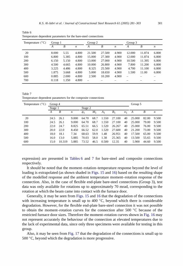
The resulting moment–rotation–temperature curves are shown inFigs. 15 and 16for both the flush and flexible end-plate bare-steel connections whilstFig. 17 showsthe elevated temperature response of composite connections for Groups 4 and 5. Theassociated temperature dependent parameters (A, B and n in the Ramberg–Osgood

300 K.S. Al-Jabri et al. / Journal of Constructional Steel Research 61 (2005) 281–303
Fig. 16. Moment–rotation–temperature curves for flexible end-plate bare-steel connection.
Fig. 17. Moment–rotation–temperature curves for flexible end-plate composite connections.
K.S. Al-Jabri et al. / Journal of Constructional Steel Research 61 (2005) 281–303 301
Table 6Temperature dependent parameters for thebare-steel connections
Temperature(◦C) Group 1 Group 2 Group 3A B n A B n A B n
20 8.000 5.55 4.800 21.500 27.500 4.900 12.000 11.874 6.800100 6.800 5.385 4.800 15.000 27.300 4.900 12.000 11.874 6.800200 6.150 5.150 4.800 13.000 27.000 4.900 10.500 11.395 6.800300 4.500 4.665 4.800 10.000 26.800 4.900 7.800 11.200 6.800400 3.225 4.486 4.800 8.325 25.500 4.900 4.700 11.100 6.800500 1.875 3.668 4.800 5.000 18.650 4.900 1.500 11.00 6.800600 0.885 2.000 4.800 2.500 10.200 4.900 – – –700 0.118 1.350 4.800 – – – – – –
Table 7Temperature dependent parametersfor the composite connections
Temperature(◦C) Group 4 Group 5Stage 1 Stage 2A B n φ1 M1 A1 B1 n1 A B n
20 24.5 26.1 9.000 64.70 68.7 1.550 27.100 40 25.000 82.00 9.500100 24.5 26.1 9.000 64.70 68.7 1.550 27.100 40 25.000 79.00 9.500200 22.0 24.7 8.825 65.51 66.5 1.520 26.267 40 25.000 76.00 9.500300 20.0 22.0 8.450 66.52 62.0 1.520 27.600 40 21.200 73.00 9.500400 18.0 18.1 7.34 68.63 59.9 1.48 26.951 40 17.500 65.00 9.500500 16.0 13.0 5.885 70.03 58.0 1.38 25.365 40 13.500 55.65 9.500600 15.0 10.319 5.885 73.52 46.5 0.500 12.35 40 5.900 44.60 9.500
expression) are presented inTables 6and 7 for bare-steel and composite connectionsrespectively.
It should be noted that the moment–rotation–temperature response beyond the level ofloading is extrapolated (as shown shaded inFigs. 15and16) based on the resulting shapeof the modelled response and the ambient temperature moment–rotation response of theconnection. Also, in the case of flexible end-plate bare-steel connections (Group 3), testdata was only available for rotations up to approximately 70 mrad, corresponding to therotation at which the beam came into contact with the furnace door.
Generally, it may be seen fromFigs. 15and16 that the degradation of the connectionswith increasing temperature is small up to 400◦C, beyond which there is considerabledegradation. However, for the flexible end-plate bare-steel connection it was not possibleto obtain the moment–rotation curves for the connection after 500◦C because of therestricted furnace door sizes. Therefore the moment–rotation curves shown inFig. 16maynot represent accurately the behaviour of the connection at elevated temperatures due tothe lack of experimental data, since only three specimens were available for testing in thisgroup.
Also, it may be seen fromFig. 17 that the degradation of the connections is small up to500◦C, beyond which the degradation is more progressive.

302 K.S. Al-Jabri et al. / Journal of Constructional Steel Research 61 (2005) 281–303
8. Conclusions
Five series of tests were conducted in order to investigate the behaviour ofsemi-rigid joints at elevated temperature. From the experimental results a family ofmoment–rotation–temperature curves was derived for these connections. It is anticipatedthat these results will be beneficial for other researchers studying the behaviour ofconnections in fire since such data are not available due to the scarcity of experimentaldatain this field.
Acknowledgments
The research was partially sponsored by the Department of the Environment undera Partners in Technology Award. Sultan Qaboos University is gratefully thanked forproviding sponsorship for the Author. CORUS is also acknowledged for supplying andfabricating the test specimens.
References
[1] Jones SW, Kirby PA, Nethercot DA. The analysis of frames with semi-rigid connections—a state-of-the-artreport. Department of Civil andStructural Engineering, University of Sheffield, UK; 1981.
[2] Investigation of Broadgate phase 8 fire. Structural fire engineering. UK: Steel Construction Institute; 1991.[3] Robinson J. New thinking on multi-storey building fires: the Cardington fire test programme—initial
conclusions. Fire Saf Eng 1997;4(6):25–6.[4] Lennon T. Personal correspondence. Watford, UK: Building Research Establishment Ltd (BRE); 1996.[5] Kruppa J. Resistance on feu des assemblage par boulous. CTICM Report, Document No. 1013-1, Centre
Technique Industrial de la Construction Metallique. France: St. Remy Chevzuese; 1976 [English translationavailable entitled Fire resistance of joints with high strength bolts].
[6] The performance of beam/column/beam connections in the BS 5950: part 8 fire test. ReportsT/RS/1380/33/82D and T/RS/1380/34/82D, British Steel (Swindon labs), Rotherham; 1982.
[7] Lawson RM. Behaviour of steel beam-to-columnconnections in fire. Struct Eng 1990;68(14):263–71.[8] Leston-Jones LC. The influence of semi-rigid connections on the performance of steel framed structures
in fire. Ph.D. Thesis, University of Sheffield; 1997.[9] Al-Jabri KS, Lennon T, Burgess IW, Plank RJ. Behaviour of steel and composite beam–column connections
in fire. J Constr Steel Res 1998;46(1–3): Paper No. 180.[10] Al-Jabri KS. The behaviour of steel and compositebeam-to-column connections in fire. Ph.D. Thesis,
University of Sheffield; 1999.[11] Boreman J, Kirby PA, Davison JB. Cardington steelframe building: tests on nine additional isolated bare
steel connections. Preliminary Report to BRE, Department of Civil and Structural Engineering, Universityof Sheffield, UK; 1995.
[12] Al-Jabri KS, Burgess IW, Plank RJ. Material andgeometrical properties for elevated-temperaturebeam–column connection tests. Research Report DCSE/98/F/5, Department ofCivil and StructuralEngineering, University of Sheffield, UK; 1998.
[13] Baker JF. Second report. steel structures research committee. Department of Scientific and IndustrialResearch, HMSO, London; 1934.
[14] Rathburn J. Elastic properties of riveted connections. Trans Amer Soc Civil Eng 1936;101:524–63.[15] Lionberger SR, Weever W. Dynamic response of frames with non-rigid connections. J Eng Mech Div ASCE
1969;95(EM1):95–114.[16] Romstad KM, Subramanian CV. Analysis of frames with partial connection rigidity. J Struct Div ASCE
1970;96(ST11):2283–300.

K.S. Al-Jabri et al. / Journal of Constructional Steel Research 61 (2005) 281–303 303
[17] Moncarz PD, Gerstle KH. Steel frames with non-linear connections. J Struct Div, ASCE 1981;107(8):1427–41.
[18] Poggi C, Zandonini R. Behaviour and strength of steel frames with semi-rigid connections. In: Chen WF,editor. Connection flexibility and steel frames. Proc. ASCE; 1985. p. 57–76.
[19] Sommer WH. Behaviour of welded header plate connection. MS Thesis, University of Toronto, Canada;1969.
[20] Fry MJ, Morris GA. Analysis of flexibly connected frames. Can J Civ Eng 1975;2(3):280–91.[21] Richard RM, Abbott BJ. Versatile elastic–plasticstress–strain formula. J Eng Mech Div, ASCE 1975;101(4):
511–5.[22] Ang KM, Morris GA. Analysis of three-dimensional frames with flexible beam–column connections. Can J
Civ Eng 1984;11(2):245–54.[23] Ramberg W, Osgood WR. Description of stress–strain curves by 3 parameters. Technical Report 902,
National Advisory Committee for Aeronautics; 1943.[24] Jones SW, Kirby PA, Nethercot DA. The analysis offrames with semi-rigid connections—a state-of-the-art
report. J Constr Steel Res 1983;3(2):2–13.[25] Chen WG, Lui EM. Column with end restraint and bending in load and resistance factor design. AISC J
1985:105–32.[26] Lui EM, Chen WG. Analysis and behaviour of flexibly jointed frames. Eng Struct 1986;8(2):107–18.[27] Kishi N, Chen WF. Database of steel beam-to-columnconnection. Structural engineering report no. CE-
STR-86-26, School of Civ. Engrg., Purdue University, West Lafayette, Ind.; 1986.[28] El-Rimawi JA. The behaviour of flexural members under fire conditions. Ph.D. Thesis, University of
Sheffield; 1989.