Balancing of rigid rotors _Integrated course - ISET Gafsa
48
Higher Institute of Technological Studies of Gafsa-Tunisia Department of Mechanical Engineering Professional Master in Mechanics of Mining Industry Systems Course & Tutorials: Balancing of rigid rotors Prepared by: Rached Nciri Technologist, Doctor Engineer Level 2- Professional Master in Mechanics of Mining Industry Systems Academic year: 2020-2021
-
Upload
khangminh22 -
Category
Documents
-
view
4 -
download
0
Transcript of Balancing of rigid rotors _Integrated course - ISET Gafsa
Higher Institute of Technological Studies of Gafsa-Tunisia
Department of Mechanical Engineering
Professional Master in Mechanics of Mining Industry Systems
Course & Tutorials: Balancing of rigid rotors
Prepared by: Rached Nciri
Technologist, Doctor Engineer
Level 2- Professional Master in Mechanics of Mining Industry Systems
Academic year: 2020-2021

Foreword
The content of this material consists of a course and some tutorials about
the balancing of rigid rotors. It is addressed to the students preparing the
professional master in Mechanics of Mining Industry Systems, taught in the
Department of Mechanical Engineering of the Higher Institute of Technological
Studies of Gafsa-Tunisia. More globally, all students who receive a
technological education in mechanical engineering can benefit from this
material. This is a first version that can be improved and updated whenever
required.

BALANCING OF RIGID ROTORS
COURSE & TUTORIALS
• Domain : Mechanical Engineering
• Level : M2-MSIM-S3
• Prerequisites: Applied License in Mechanical Engineering.
• Number of hours: 21 hours.
• Goals :
- Understanding the different types of unbalances that may
occur on rotors.
- Understanding the different types of balancing that permit to
correct unbalances on rotors.
- Knowing the specific equipment for rotor balancing.
- Understanding the principal rules associated to the balancing
of rigid rotors (Standards ISO 21940-11:2016).
- Master the application of static balancing.
- Master the application of dynamic balancing.

Table of contents
CHAPTER 1. ROTORS UNBALANCES AND BALANCING: TECHNOLOGICAL
OVERVIEW. 5
1. Context............................................................................................................................... 5
2. Principle ............................................................................................................................. 5
3. Types of unbalance ............................................................................................................ 5
3.1. Static unbalance .......................................................................................................... 5
3.2. Couple unbalance ........................................................................................................ 6
3.3. Quasi-static unbalance ................................................................................................ 6
3.4. Dynamic unbalance ..................................................................................................... 7
4. Types of balancing ............................................................................................................. 8
5. References ......................................................................................................................... 9
CHAPTER 2. STATIC BALANCING (SINGLE PLANE BALANCING). ............... 10
1. Static balancing setup ...................................................................................................... 10
2. Static balancing methodology ......................................................................................... 10
3. Static balancing techniques ............................................................................................. 11
4. References ....................................................................................................................... 14
CHAPTER 3. DYNAMIC BALANCING (TWO PLANES BALANCING). .............. 15
1. Dynamic balancing setup ................................................................................................. 15
2. Static balancing methodology ......................................................................................... 15
3. Dynamic balancing techniques ........................................................................................ 17
4. References ....................................................................................................................... 18
CHAPTER 4. SPECIFIC EQUIPMENT FOR ROTOR BALANCING. .................... 19
1. Balancing methods .......................................................................................................... 19
1.1. Balancing in workshop ............................................................................................. 19
1.2. In-situ balancing........................................................................................................ 20
2. Devices for balancing setup ............................................................................................. 20
3. References ....................................................................................................................... 23

CHAPTER 5. USEFUL STANDARDS FOR THE BALANCING OF RIGID
ROTORS. 25
1. ISO balancing grades ....................................................................................................... 25
2. Permissible Residual Unbalance ..................................................................................... 26
3. Maximum Residual Mass and Trial mass........................................................................ 29
4. Mass and phase correction ............................................................................................... 29
5. Admissible residual vibration .......................................................................................... 29
6. References ....................................................................................................................... 30
CHAPTER 6. STATIC BALANCING TUTORIAL. .................................................... 31
1. Problem statement ........................................................................................................... 31
2. Technological answers .................................................................................................... 37
CHAPTER 7. DYNAMIC BALANCING TUTORIAL. ............................................... 42
1. Problem statement ........................................................................................................... 42
2. Technological answers .................................................................................................... 43
Higher Institute of Technological Studies_Gafsa-Tunisia Balancing of rigid rotors
Department of Mechanical Engineering Rotors unbalances and balancing: Technological overview
5 Rached Nciri; Technologist, D. Eng.
Chapter 1. Rotors unbalances and balancing: Technological overview.
1. Context
The balancing aims to correct a mass unbalance in a rotor of rotating machines (rotor of
electric machines, rotor of turbines, rotor of propeller, rotor of pumps…etc.). This allows the
vibration levels to be reduced at the rotational speed of the rotor. The vibration level is an
important indicator reflecting the condition of the machine in terms of condition-based
maintenance. The high vibration level accelerates the wear of the rotor, decreases the life of
the bearings, generates an annoying noise and makes the work conditions unsafe. In this
context, the balancing of rotating machines takes on all its interest [1.1-1.4]
2. Principle
The rotor of a rotating machine naturally has a mass distribution that is not perfectly
homogeneous in its volume. This non-homogeneity is called unbalance. The axis of rotation is
then not coincident with the axis of inertia. This unbalance is equivalent to a point unbalance
mass, located at a given distance from the axis of rotation, and it generates a rotating force,
under the form of a centrifugal force [1.5]:
{ ( )
[ ][ ]
[ ][ ]s/rd
mR
kgm
NF
tmRF
centrifuge
lcentrifuga
locity Angular ve :
radius Unbalance:
mass punctual Unbalance:
force lCentrifuga :
withsin2
unbalance Rotating
ω
ωω=
3. Types of unbalance
Four types of unbalance are distinguished [1.6]: static unbalance, couple unbalance, quasi-
static unbalance and dynamic unbalance.
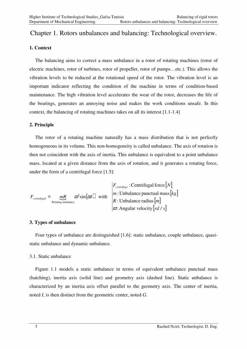
3.1. Static unbalance
Figure 1.1 models a static unbalance in terms of equivalent unbalance punctual mass
(hatching), inertia axis (solid line) and geometry axis (dashed line). Static unbalance is
characterized by an inertia axis offset parallel to the geometry axis. The center of inertia,
noted I, is then distinct from the geometric center, noted G.

Higher Institute of Technological Studies_Gafsa-Tunisia Balancing of rigid rotors
Department of Mechanical Engineering Rotors unbalances and balancing: Technological overview
6 Rached Nciri; Technologist, D. Eng.
3.2. Couple unbalance
Figure 1.2 models a couple unbalance in terms of equivalent unbalance punctual mass
(hatching), inertia axis (solid line) and geometry axis (dashed line). Couple unbalance is
characterized by an inertia axis secant to the geometry axis at the geometric center. The center
of inertia, noted I, and the geometric center, noted G, are then merged.
Figure 1.1. Static unbalance model.
Figure 1.2. Couple unbalance model.
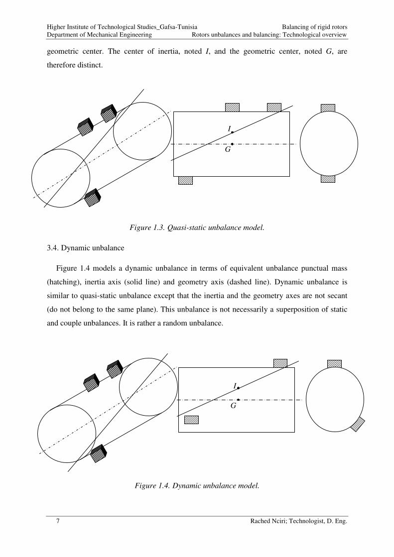
3.3. Quasi-static unbalance
Figure 1.3 models a quasi-static unbalance in terms of equivalent unbalance punctual mass
(hatching), inertia axis (solid line) and geometry axis (dashed line). Quasi-static unbalance
represents the superposition of static and couple unbalances. This type of unbalance is
characterized by an inertia axis secant to the geometry axis at a point different from the
G
I
I
G
Higher Institute of Technological Studies_Gafsa-Tunisia Balancing of rigid rotors
Department of Mechanical Engineering Rotors unbalances and balancing: Technological overview
7 Rached Nciri; Technologist, D. Eng.
geometric center. The center of inertia, noted I, and the geometric center, noted G, are
therefore distinct.
Figure 1.3. Quasi-static unbalance model.
3.4. Dynamic unbalance
Figure 1.4 models a dynamic unbalance in terms of equivalent unbalance punctual mass
(hatching), inertia axis (solid line) and geometry axis (dashed line). Dynamic unbalance is
similar to quasi-static unbalance except that the inertia and the geometry axes are not secant
(do not belong to the same plane). This unbalance is not necessarily a superposition of static
and couple unbalances. It is rather a random unbalance.
Figure 1.4. Dynamic unbalance model.
I
G
I
G

Higher Institute of Technological Studies_Gafsa-Tunisia Balancing of rigid rotors
Department of Mechanical Engineering Rotors unbalances and balancing: Technological overview
8 Rached Nciri; Technologist, D. Eng.
4. Types of balancing
Balancing makes it possible to reduce or even cancel the centrifugal force, by acting on the
reduction of unbalance. For rigid rotors, there are 2 types of balancing [1.7]:
• Static balancing (single plane): It consists in bringing the center of inertia of the
rotor back to the axis of rotation. Therefore, gravity will not move the rotor regardless
of its angular position. The rotor is said, then, to be statically balanced. Chapter 2 will
be devoted to static balancing. The technical procedure and technological details of
such balancing will be provided.
• Dynamic balancing (two planes): It consists in making one of the main inertia axes
of the rotor coincide with the axis of rotation. This is possible by a well-studied
addition or removal of material. Chapter 3 will be devoted to dynamic balancing. The
technical procedure and technological details of such balancing will be provided.
The choice of the correct balancing: static or dynamic depends mainly on two parameters:
the size and the rotational speed of the rotor (Figure 1.5 and Table 1.1) [1.8]
Table 1.1.
Figure 1.5. Rotor size.
Table 1.1. Choice of balancing type for rigid rotors.
Size Rotational speed Balancing type
5.0≤D
L
rpm 1000≤N Static (Single plane)
rpm 1000>N Dynamic (Two plane)
5.0>D
L
rpm 150≤N Static(Single plane)
rpm 150>N Dynamic (Two plane)
L
D

Higher Institute of Technological Studies_Gafsa-Tunisia Balancing of rigid rotors
Department of Mechanical Engineering Rotors unbalances and balancing: Technological overview
9 Rached Nciri; Technologist, D. Eng.
5. References
[1.1] Derek Norfield, Practical Balancing of Rotating Machinery, Elsevier Science 2005,
ISBN 978-1-85617-465-7, https://doi.org/10.1016/B978-1-85617-465-7.X5000-1
[1.2] Michael I. Friswell, John E. T. Penny, Seamus D. Garvey
and Arthur W. Lees, Dynamics of Rotating Machines, Cambridge University Press 2010,
ISBN: 9780511780509, https://doi.org/10.1017/CBO9780511780509
[1.3] Robert B. and McMillan, Rotating Machinery: Practical Solutions to Unbalance and
Misalignment, River Publishers 1st Ed. 2003, ISBN: 9780824750527
[1.4] J B Wilcox, Dynamic Balancing of Rotating Machinery, Pitman 1967, ISBN-13: 978-
0273429593
[1.5] Djaidir Benrabeh, Ahmed Hafaifa and Kouzou Abdellah, Faults detection in gas turbine
rotor using vibration analysis under varying conditions, Journal of Theoretical and Applied
Mechanics 55(02) (2017) 393-406, https://doi.org/10.15632/jtam-pl.55.2.393
[1.6] Balancing: Static, Coupled and Dynamic,
https://community.sw.siemens.com/s/article/balancing-static-coupled-and-dynamic, Access
date: December, 16 2020 14:27 GMT
[1.7] John Vaughan, Static and Dynamic balancing, Bruel & Kjaer application notes, 2nd
Ed.
https://pearl-
hifi.com/06_Lit_Archive/15_Mfrs_Publications/10_Bruel_Kjaer/04_App_Notes/Static_and_
Dynamic_Balancing_2nd_Edn.pdf, Access date: December, 16 2020 14:50 GMT
[1.8] Jaafar Alsalaet, Dynamic Balancing and Shaft Alignment, College of Engineering-
University of Basrah 1st
Ed. 2015

Higher Institute of Technological Studies_Gafsa-Tunisia Balancing of rigid rotors
Department of Mechanical Engineering Static balancing (single plane balancing)
10 Rached Nciri; Technologist, D. Eng.
Chapter 2. Static balancing (single plane balancing).
1. Static balancing setup
The static balancing setup [2.1] permits to measure the amplitude V and the phase φ of the
vibration on a rotor bearing. Figure 2.1 depicts the main devices connected on this setup.
Figure 2.1. Static balancing setup.
2. Static balancing methodology
The static balancing (single plane balancing) procedure [2.2] can be presented by detailing
the general balancing process:
Establishment of the initial conditions of the
unbalance (V0 and φ0)
Calculation, application of the trial mass and
establishment of the conditions for
{unbalance + trial mass Mt}
Place the accelerometer sensor on the
vibrating bearing in order to get the
sinusoidal function of the vibration
(amplitude V0)
Place the rotation sensor and get the pulse
function of the rotation
Determine the angular phase shift φ0 between
the vibration function and the rotation
Place the accelerometer sensor on the
vibrating bearing and get the sinusoidal
function of the vibration (amplitude V1)
Place the rotation sensor and get the pulse
function of the rotation.
Determine the angular phase shift φ1 between
the vibration function and the rotation
Calculate [2.3] and apply the trial mass Mt on
the balancing plane on an arbitrary radial
position Rt.
Accelerometer
sensor
Rotation
sensor
Amplitude-phase
analyzer
Rotor
V ; φ
Higher Institute of Technological Studies_Gafsa-Tunisia Balancing of rigid rotors
Department of Mechanical Engineering Static balancing (single plane balancing)
11 Rached Nciri; Technologist, D. Eng.
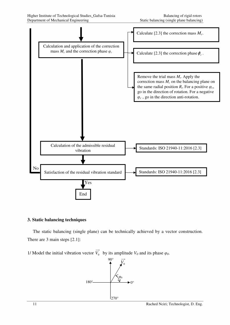
3. Static balancing techniques
The static balancing (single plane) can be technically achieved by a vector construction.
There are 3 main steps [2.1]:
1/ Model the initial vibration vector 0V by its amplitude V0 and its phase φ0.
Calculation and application of the correction
mass Mc and the correction phase φc
Remove the trial mass Mt. Apply the
correction mass Mc on the balancing plane on
the same radial position Rt. For a positive φc, go in the direction of rotation. For a negative
φc , go in the direction anti-rotation.
Calculation of the admissible residual
vibration
Satisfaction of the residual vibration standard
Yes
End
No
Calculate [2.3] the correction mass Mc.
Calculate [2.3] the correction phase cϕ .
Standards: ISO 21940-11:2016 [2.3]
0°
90° 0V
φ0
Standards: ISO 21940-11:2016 [2.3]
180°
270°
Higher Institute of Technological Studies_Gafsa-Tunisia Balancing of rigid rotors
Department of Mechanical Engineering Static balancing (single plane balancing)
12 Rached Nciri; Technologist, D. Eng.
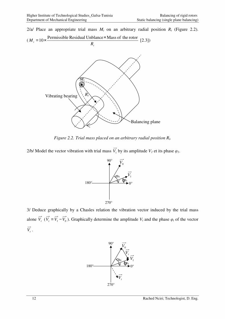
2/a/ Place an appropriate trial mass Mt on an arbitrary radial position Rt (Figure 2.2).
(t
tR
Mrotor theof Mass UnblanceResidual ePermissibl
10××= [2.3])
Figure 2.2. Trial mass placed on an arbitrary radial position Rt.
2/b/ Model the vector vibration with trial mass 1V by its amplitude V1 et its phase φ1.
3/ Deduce graphically by a Chasles relation the vibration vector induced by the trial mass
alone tV ( 01 VVVt −= ). Graphically determine the amplitude Vt and the phase φt of the vector
tV .
0°
90° 0V
φ0
φ1
0°
90° 0V
φ0
φ1
tV
1V
tV
1V
Mt
Rt Vibrating bearing
Balancing plane
180°
270°
180°
270°

Higher Institute of Technological Studies_Gafsa-Tunisia Balancing of rigid rotors
Department of Mechanical Engineering Static balancing (single plane balancing)
13 Rached Nciri; Technologist, D. Eng.
3/a/ Knowing the value of φ0 and φt, deduce the angular position φc of the correction mass Mc
in relation to the angular position of the trial mass Mt. ( tc ϕϕϕ −+= 1800 [2.3]).
3/b/ Knowing the value of the trial mass Mt, the amplitude of the initial vibration V0 and the
amplitude of the vibration vector induced by the trial mass alone Vt, deduce the value of the
correction mass Mc. (t
tcV
VMM 0= [2.3]).
3/c/ Remove the trial mass Mt. Place the correction mass Mc on the radial position Rt and its
angular position φc. The angular position φc is counted from the angular position of the
removed trial mass as it is depicted by Figure 2.3. For a positive φc, go in the direction of the
rotation of the rotor. For a negative φc, go in the direction anti-rotation of the rotor.
Figure 2.3. Appropriate radial and angular positions of a correction mass.
0°
90° 0V
φ0
φ1
tV
tV
1V
cV
φc
Mt
Rt
Mc
Rc=Rt
φc
Removed trial mass
180°
270°

Higher Institute of Technological Studies_Gafsa-Tunisia Balancing of rigid rotors
Department of Mechanical Engineering Static balancing (single plane balancing)
14 Rached Nciri; Technologist, D. Eng.
4. References
[2.1] John Vaughan, Static and Dynamic balancing, Bruel & Kjaer application notes, 2nd
Ed.
https://pearl-
hifi.com/06_Lit_Archive/15_Mfrs_Publications/10_Bruel_Kjaer/04_App_Notes/Static_and_
Dynamic_Balancing_2nd_Edn.pdf, Access date: December, 16 2020 02:50 GMT
[2.2] VibroMetra System, Application note: Basics of balancing,
https://www.mmf.de/pdf/an31e-vm-bal.pdf, Access date: December, 23 2020 11:04 GMT
[2.3] International Organization for Standardization, ISO 21940-11:2016, Mechanical
vibration — Rotor balancing — Part 11: Procedures and tolerances for rotors with rigid
behaviour, September 2016
Higher Institute of Technological Studies_Gafsa-Tunisia Balancing of rigid rotors
Department of Mechanical Engineering Dynamic balancing (Two planes balancing)
15 Rached Nciri; Technologist, D. Eng.
Chapter 3. Dynamic balancing (Two planes balancing).
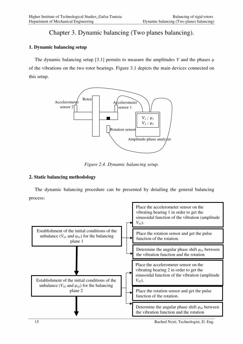
1. Dynamic balancing setup
The dynamic balancing setup [3.1] permits to measure the amplitudes V and the phases φ
of the vibrations on the two rotor bearings. Figure 3.1 depicts the main devices connected on
this setup.
Figure 2.4. Dynamic balancing setup.
2. Static balancing methodology
The dynamic balancing procedure can be presented by detailing the general balancing
process:
Establishment of the initial conditions of the
unbalance (V01 and φ01) for the balancing
plane 1
Place the accelerometer sensor on the
vibrating bearing 1 in order to get the
sinusoidal function of the vibration (amplitude
V01).
Place the rotation sensor and get the pulse
function of the rotation.
Determine the angular phase shift φ01 between
the vibration function and the rotation
Establishment of the initial conditions of the
unbalance (V02 and φ02) for the balancing
plane 2
Place the accelerometer sensor on the
vibrating bearing 2 in order to get the
sinusoidal function of the vibration (amplitude
V02).
Place the rotation sensor and get the pulse
function of the rotation.
Determine the angular phase shift φ02 between
the vibration function and the rotation
Accelerometer
sensor 1
Rotation sensor
Amplitude-phase analyzer
Rotor
V1 ; φ1
V2 ; φ2
Accelerometer
sensor 2

Higher Institute of Technological Studies_Gafsa-Tunisia Balancing of rigid rotors
Department of Mechanical Engineering Dynamic balancing (Two planes balancing)
16 Rached Nciri; Technologist, D. Eng.
Calculation, application of the trial mass and
establishment of the conditions for
{unbalance + trial mass Mt} for the balancing
plane 1
Place the accelerometer sensor on the
vibrating bearing 1 and get the sinusoidal
function of the vibration (amplitude V11)
Place the rotation sensor and get the pulse
function of the rotation.
Determine the angular phase shift φ11 between
the vibration function and the rotation
Calculate [3.2] and apply the trial mass Mt on
the balancing plane 1 on an arbitrary radial
position Rt.
Place the accelerometer sensor on the
vibrating bearing 2 and get the sinusoidal
function of the vibration (amplitude V21)
Place the rotation sensor and get the pulse
function of the rotation.
Determine the angular phase shift φ21 between
the vibration function and the rotation
Calculation, application of the trial mass and
establishment of the conditions for
{unbalance + trial mass Mt} for the balancing
plane 2
Place the accelerometer sensor on the
vibrating bearing 1 and get the sinusoidal
function of the vibration (amplitude V12)
Place the rotation sensor and get the pulse
function of the rotation.
Determine the angular phase shift φ12 between
the vibration function and the rotation
Remove the trial mass Mt from the balancing
plane 1 and apply it on the balancing plane 2
on the same arbitrary radial position Rt.
Place the accelerometer sensor on the
vibrating bearing 2 and get the sinusoidal
function of the vibration (amplitude V22)
Place the rotation sensor and get the pulse
function of the rotation.
Determine the angular phase shift φ22 between
the vibration function and the rotation

Higher Institute of Technological Studies_Gafsa-Tunisia Balancing of rigid rotors
Department of Mechanical Engineering Dynamic balancing (Two planes balancing)
17 Rached Nciri; Technologist, D. Eng.
3. Dynamic balancing techniques
The principle of the dynamic balancing [3.3] technique is based on the application of the
static balancing technique on the two balancing planes. However, we must take into account
the effect of the unbalance of the plane 1 on the vibration of the bearing 2, and the unbalance
of the plane 2 on the vibration of the bearing 1. The calculation is then more complicated.
(For more details, see Tutorial 2_Dynamic balancing).
Removing of the trial mass Mt, calculation
and application of the correction mass Mc1
and Mc2 and the correction phase φc1 and φc2
on the balancing planes 1 and 2 respectively.
Adjust the correction radius.
Measurement of the residual vibration Vr
Calculation of the admissible residual
vibration admrV ,
Satisfaction of the residual vibration
standards
Yes
End
No
Standards [3.2]
Standards [3.2]
Standards [3.2]
Higher Institute of Technological Studies_Gafsa-Tunisia Balancing of rigid rotors
Department of Mechanical Engineering Dynamic balancing (Two planes balancing)
18 Rached Nciri; Technologist, D. Eng.
4. References
[3.1] John Vaughan, Static and Dynamic balancing, Bruel & Kjaer application notes, 2nd
Ed.
https://pearl-
hifi.com/06_Lit_Archive/15_Mfrs_Publications/10_Bruel_Kjaer/04_App_Notes/Static_and_
Dynamic_Balancing_2nd_Edn.pdf, Access date: December, 16 2020 02:50 GMT
[3.2] International Organization for Standardization, ISO 21940-11:2016, Mechanical
vibration — Rotor balancing — Part 11: Procedures and tolerances for rotors with rigid
behaviour, September 2016
[3.3] VibroMetra System, Application note: Basics of balancing,
https://www.mmf.de/pdf/an31e-vm-bal.pdf, Access date: December, 23 2020 11:04 GMT
Higher Institute of Technological Studies_Gafsa-Tunisia Balancing of rigid rotors
Department of Mechanical Engineering Specific equipment for rotor balancing
19 Rached Nciri; Technologist, D. Eng.
Chapter 4. Specific equipment for rotor balancing.
1. Balancing methods
There are two balancing methods: in workshop and in-situ (known also as field balancing)
[4.1].
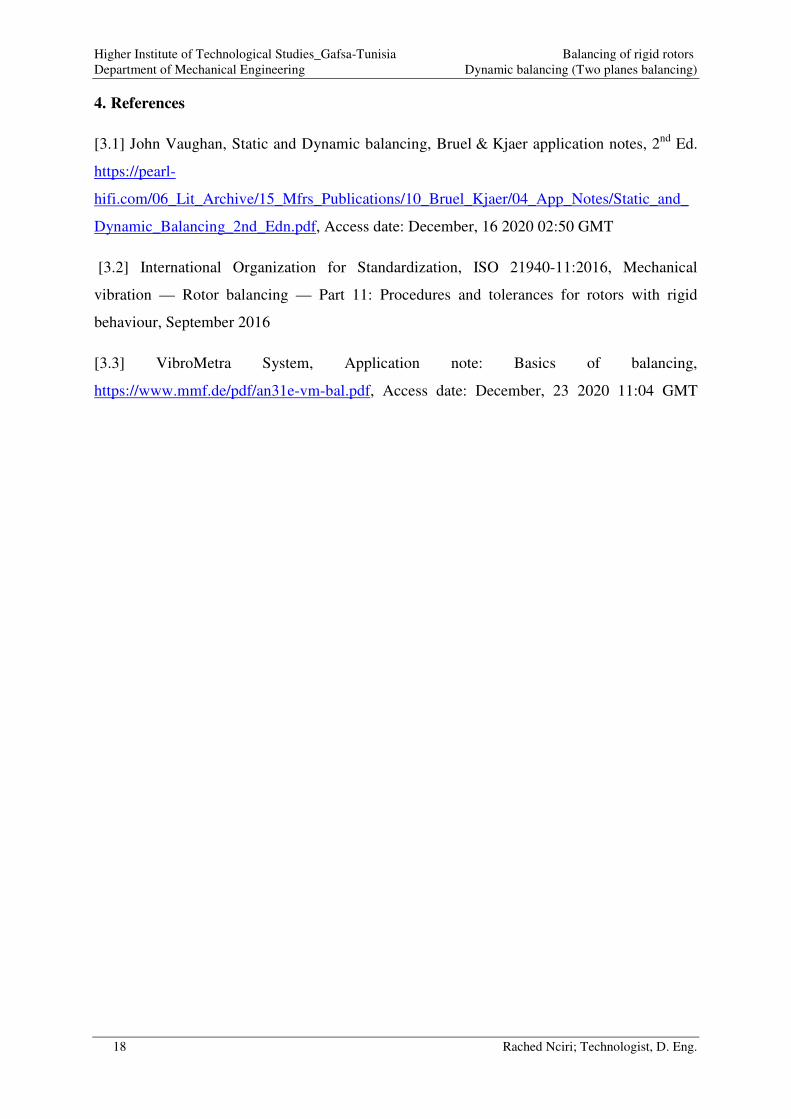
1.1. Balancing in workshop
The rotor is dismantled and then installed on a balancing machine located in a workshop.
This balancing method is well suited to serial work (serial balancing of rotors). Figure 4.1
shows a balancing machine with an axial drive. Figure 4.2 shows a balancing machine with a
radial drive.
Figure 3.1. Balancing machine with axial drive [4.2].
Figure 3.2. Balancing machine with radial drive [4.3].

Higher Institute of Technological Studies_Gafsa-Tunisia Balancing of rigid rotors
Department of Mechanical Engineering Specific equipment for rotor balancing
20 Rached Nciri; Technologist, D. Eng.
1.2. In-situ balancing
In-situ balancing consists of balancing the rotor without dismantling it (while remaining on
its own bearings). This in-situ balancing is the most widely practiced since it essentially
allows:
• Take into account the actual operating conditions of the rotor to be balanced (speed,
load, gap, etc…).
• Avoid dismantling, reassembly and realignment of the rotors to be balanced.
Figure 4.3 shows an in-situ balancing.
Figure 3.3. In-situ balancing [4.4].
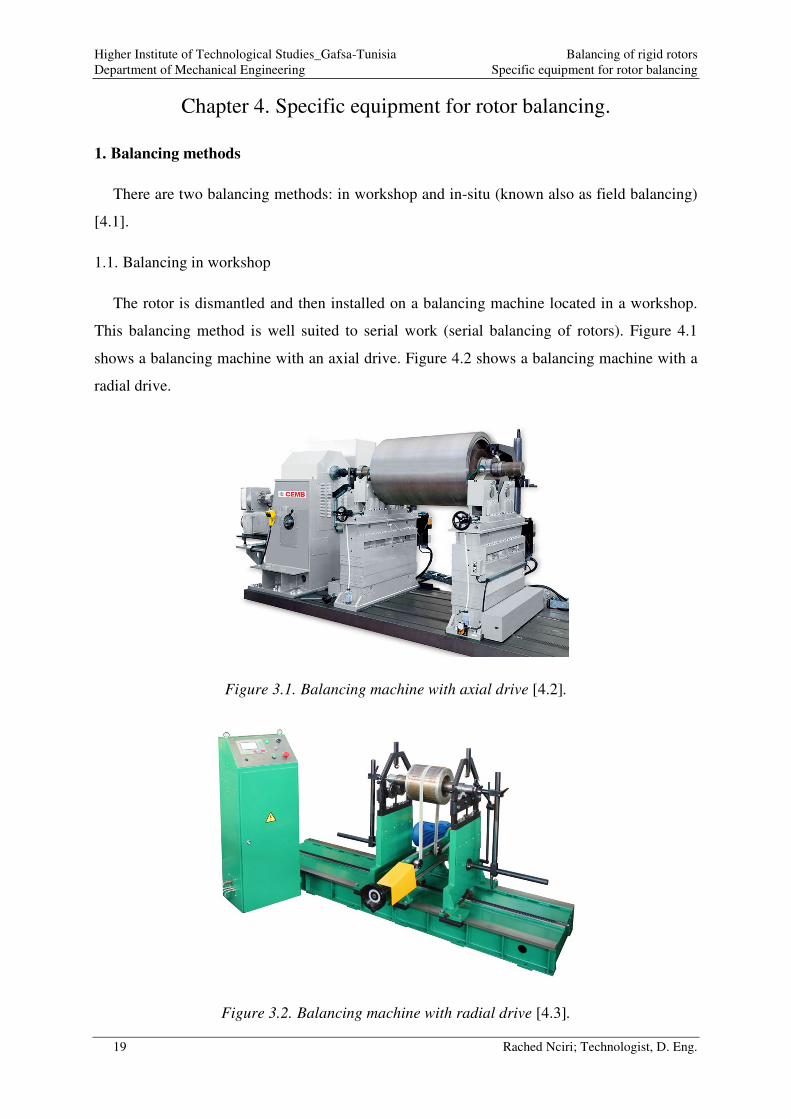
2. Devices for balancing setup
Static or dynamic balancing is carried out using a set of specific devices connected as
shown in Figure 4.4 and Figure 4.5.
Higher Institute of Technological Studies_Gafsa-Tunisia Balancing of rigid rotors
Department of Mechanical Engineering Specific equipment for rotor balancing
21 Rached Nciri; Technologist, D. Eng.
Figure 3.4. Static balancing equipment [4.5].
Figure 3.5. Dynamic balancing equipment [4.6].
Shaft
Accelerometer
sensor
Rotation
sensor
Balancing
software
Balancing plane
Rotation sensor
Accelerometer
sensors

Higher Institute of Technological Studies_Gafsa-Tunisia Balancing of rigid rotors
Department of Mechanical Engineering Specific equipment for rotor balancing
22 Rached Nciri; Technologist, D. Eng.
• Accelerometer sensor: to measure the vibration function (Figure 4.6).
Figure 3.6. Accelerometer sensor [4.7].
• Rotation sensor : to measure the rotation function
Figure 3.7. Rotation sensor [4.8].
Higher Institute of Technological Studies_Gafsa-Tunisia Balancing of rigid rotors
Department of Mechanical Engineering Specific equipment for rotor balancing
23 Rached Nciri; Technologist, D. Eng.
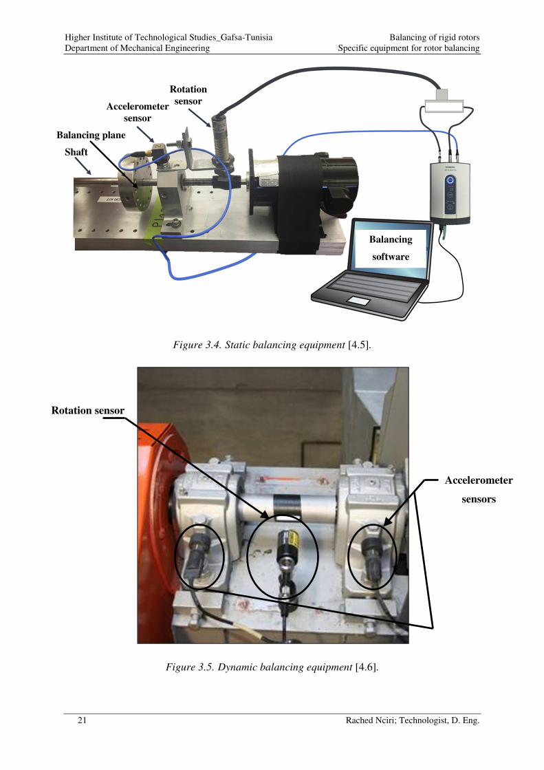
• Amplitude-phase analyzer: to analyze the data sent by the accelerometer and the
rotation sensors and then determine the vibration amplitude and calculate the phase
shift between the vibration function and the rotation function.
Figure 3.8. Amplitude-phase analyzer [4.9].
3. References
[4.1] Jaafar Alsalaet, Dynamic Balancing and Shaft Alignment, College of Engineering-
University of Basrah 1st
Ed. 2015
[4.2] CEMB, Horizontal balancing machine Z50000-G-GV,
https://www.directindustry.fr/prod/cemb/product-7363-439463.html, Access date: December,
23 2020 17:54 GMT
[4.3] Vneshtorg--Micron ltd., Horizontal balancing machine 9K716,
https://www.directindustry.com/prod/vneshtorg-micron-ltd/product-63357-1575868.html,
Access date: December, 23 2020 18:09 GMT
[4.4] PRUFTECHNIK, Equilibrage sur site,
https://www.usinenouvelle.com/expo/equilibrage-sur-site-p79071553.html, Access date:
December, 23 2020 18:28 GMT

Higher Institute of Technological Studies_Gafsa-Tunisia Balancing of rigid rotors
Department of Mechanical Engineering Specific equipment for rotor balancing
24 Rached Nciri; Technologist, D. Eng.
[4.5] SIEMENS, Physical setup for single plane balancing,
https://community.sw.siemens.com/s/article/single-plane-balancing-in-
simcenter-testlab, Access date: December, 23 2020 18:36 GMT
[4.6] Spectrum, https://spectrumscientific.com.ph/product/rpm-sensors-keyphasers/, Access
date: December, 24 2020 08:06 GMT
[4.7] Starmeter, Vibration Meter VM-6360, http://www.starmeter.cn/Vibration-Meter-VM-
6360-pd6672544.html, Access date: December, 24 2020 08:46 GMT
[4.8]NEXUS AUTOMECH, Cylindrical photoelectric Sensor / LASER / IP67 / IP69K –
S186ELD Plastic barrel LASER emitter,
https://www.nexusautomech.com/product/cylindrical-photoelectric-sensor-laser-ip67-ip69k-
s186eld-plastic-barrel-laser-emitter/, Access date: December, 24 2020 09:20 GMT
[4.9] CEMB, Predictive maintenance vibration analyzer N600,
https://www.directindustry.com/prod/cemb/product-7363-1533891.html, Access date:
December, 24 2020 09:31 GMT
Higher Institute of Technological Studies_Gafsa-Tunisia Balancing of rigid rotors
Department of Mechanical Engineering Useful Standards for the balancing of rigid rotors
25 Rached Nciri; Technologist, D. Eng.
Chapter 5. Useful standards for the balancing of rigid rotors.
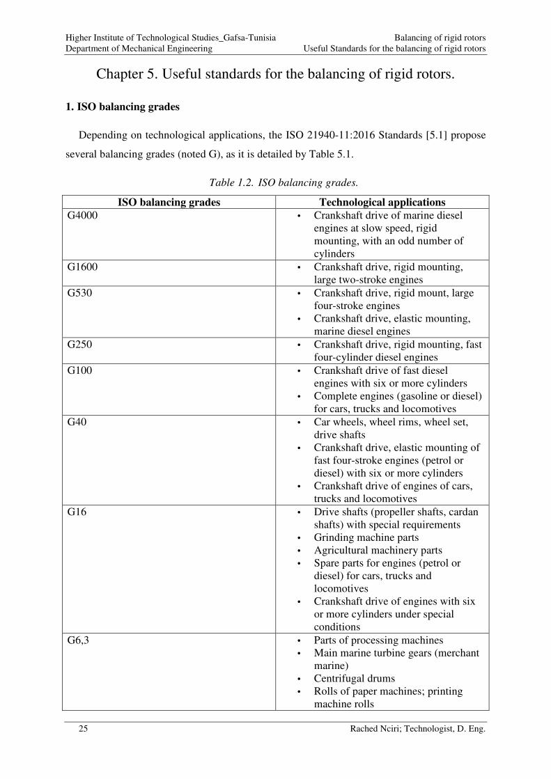
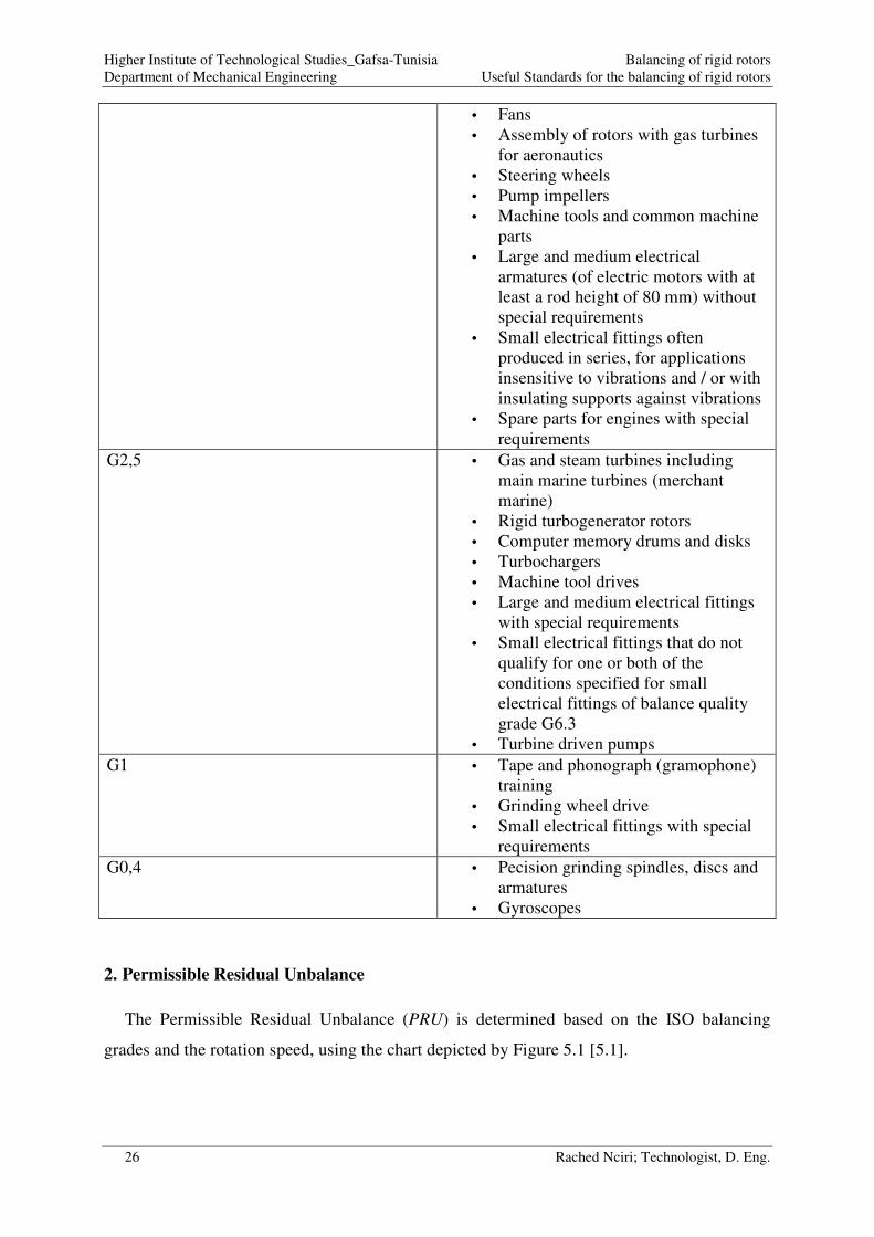
1. ISO balancing grades
Depending on technological applications, the ISO 21940-11:2016 Standards [5.1] propose
several balancing grades (noted G), as it is detailed by Table 5.1.
Table 1.2. ISO balancing grades.
ISO balancing grades Technological applications
G4000 • Crankshaft drive of marine diesel
engines at slow speed, rigid
mounting, with an odd number of
cylinders
G1600 • Crankshaft drive, rigid mounting,
large two-stroke engines
G530 • Crankshaft drive, rigid mount, large
four-stroke engines
• Crankshaft drive, elastic mounting,
marine diesel engines
G250 • Crankshaft drive, rigid mounting, fast
four-cylinder diesel engines
G100 • Crankshaft drive of fast diesel
engines with six or more cylinders
• Complete engines (gasoline or diesel)
for cars, trucks and locomotives
G40 • Car wheels, wheel rims, wheel set,
drive shafts
• Crankshaft drive, elastic mounting of
fast four-stroke engines (petrol or
diesel) with six or more cylinders
• Crankshaft drive of engines of cars,
trucks and locomotives
G16 • Drive shafts (propeller shafts, cardan
shafts) with special requirements
• Grinding machine parts
• Agricultural machinery parts
• Spare parts for engines (petrol or
diesel) for cars, trucks and
locomotives
• Crankshaft drive of engines with six
or more cylinders under special
conditions
G6,3 • Parts of processing machines
• Main marine turbine gears (merchant
marine)
• Centrifugal drums
• Rolls of paper machines; printing
machine rolls
Higher Institute of Technological Studies_Gafsa-Tunisia Balancing of rigid rotors
Department of Mechanical Engineering Useful Standards for the balancing of rigid rotors
26 Rached Nciri; Technologist, D. Eng.
• Fans
• Assembly of rotors with gas turbines
for aeronautics
• Steering wheels
• Pump impellers
• Machine tools and common machine
parts
• Large and medium electrical
armatures (of electric motors with at
least a rod height of 80 mm) without
special requirements
• Small electrical fittings often
produced in series, for applications
insensitive to vibrations and / or with
insulating supports against vibrations
• Spare parts for engines with special
requirements
G2,5 • Gas and steam turbines including
main marine turbines (merchant
marine)
• Rigid turbogenerator rotors
• Computer memory drums and disks
• Turbochargers
• Machine tool drives
• Large and medium electrical fittings
with special requirements
• Small electrical fittings that do not
qualify for one or both of the
conditions specified for small
electrical fittings of balance quality
grade G6.3
• Turbine driven pumps
G1 • Tape and phonograph (gramophone)
training
• Grinding wheel drive
• Small electrical fittings with special
requirements
G0,4 • Pecision grinding spindles, discs and
armatures
• Gyroscopes
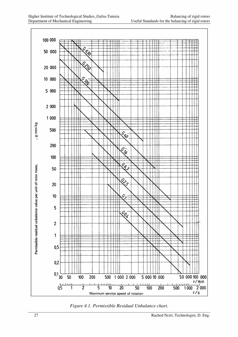
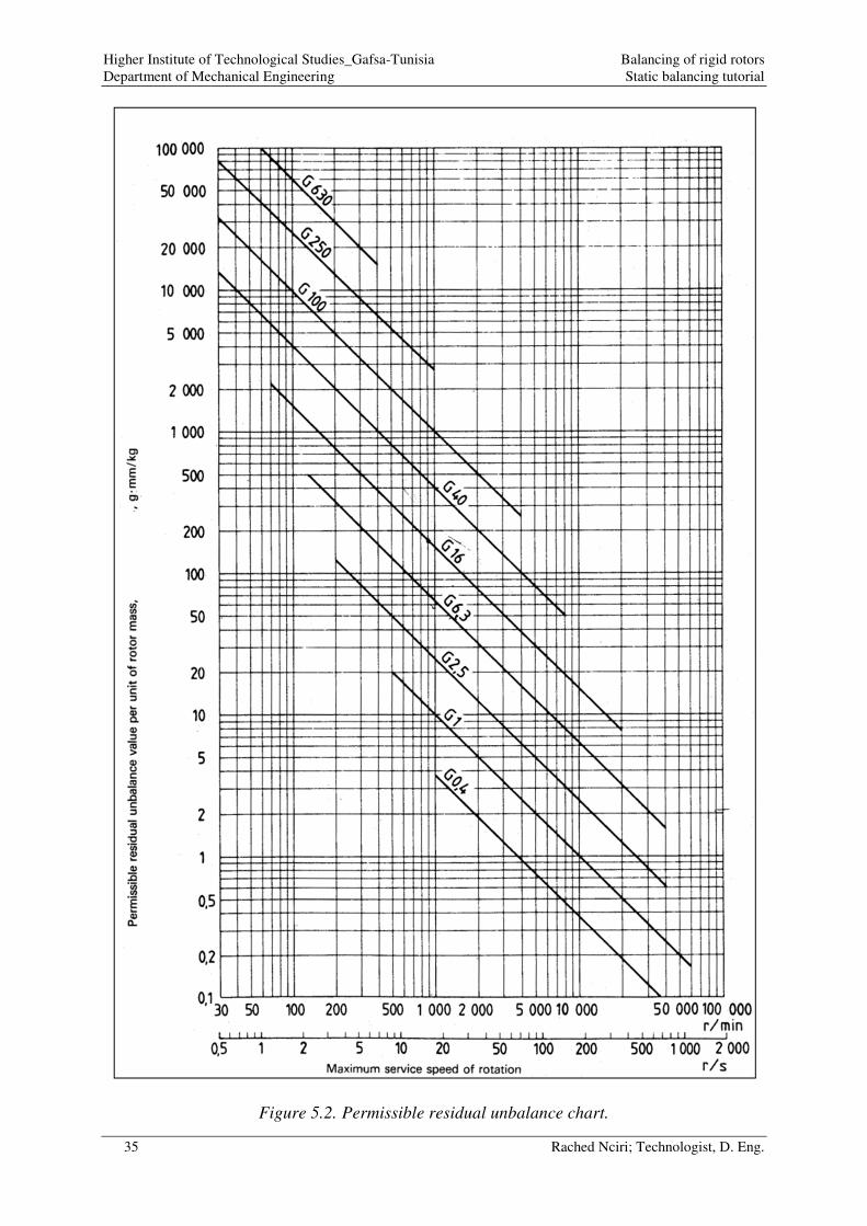
2. Permissible Residual Unbalance
The Permissible Residual Unbalance (PRU) is determined based on the ISO balancing
grades and the rotation speed, using the chart depicted by Figure 5.1 [5.1].
Higher Institute of Technological Studies_Gafsa-Tunisia Balancing of rigid rotors
Department of Mechanical Engineering Useful Standards for the balancing of rigid rotors
27 Rached Nciri; Technologist, D. Eng.
Figure 4.1. Permissible Residual Unbalance chart.

Higher Institute of Technological Studies_Gafsa-Tunisia Balancing of rigid rotors
Department of Mechanical Engineering Useful Standards for the balancing of rigid rotors
28 Rached Nciri; Technologist, D. Eng.
Application example
A propeller driveshaft (G16) rotating at 1000 rpm will have a Permissible Residual
Unbalance (PRU) in the order of PRU=150 g.mm/kg as it is depicted by Figure 5.2.
Figure 4.2. Determination of Permissible Residual Unbalance.
Higher Institute of Technological Studies_Gafsa-Tunisia Balancing of rigid rotors
Department of Mechanical Engineering Useful Standards for the balancing of rigid rotors
29 Rached Nciri; Technologist, D. Eng.
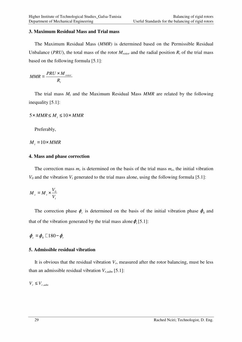
3. Maximum Residual Mass and Trial mass
The Maximum Residual Mass (MMR) is determined based on the Permissible Residual
Unbalance (PRU), the total mass of the rotor Mrotor and the radial position Rt of the trial mass
based on the following formula [5.1]:
t
rotor
R
MPRUMMR
×=
The trial mass Mt and the Maximum Residual Mass MMR are related by the following
inequality [5.1]:
MMRMMMR t ×≤≤× 105
Preferably,
MMRM t ×=10
4. Mass and phase correction
The correction mass mc is determined on the basis of the trial mass me, the initial vibration
V0 and the vibration Vt generated to the trial mass alone, using the following formula [5.1]:
t
tcV
VMM 0×=
The correction phase cϕ is determined on the basis of the initial vibration phase 0ϕ and
that of the vibration generated by the trial mass alone tϕ [5.1]:
tc ϕϕϕ −+= 1800
5. Admissible residual vibration
It is obvious that the residual vibration Vr, measured after the rotor balancing, must be less
than an admissible residual vibration Vr,adm [5.1]:
admrr VV ,≤
Higher Institute of Technological Studies_Gafsa-Tunisia Balancing of rigid rotors
Department of Mechanical Engineering Useful Standards for the balancing of rigid rotors
30 Rached Nciri; Technologist, D. Eng.
The admissible residual vibration Vr,adm is determined as a function of the vibration
generated by the trial mass alone Vt, the Maximum Residual Mass MMR and the trial mass Mt
[5.1]:
t
tadmrM
MMRVV ×=,
Since it is preferably that [5.1]:
MMRM t ×=10
The admissible residual vibration Vr,adm becomes [5.1]:
tadmr VV ×= 1.0,
6. References
[5.1] International Organization for Standardization, ISO 21940-11:2016, Mechanical
vibration — Rotor balancing — Part 11: Procedures and tolerances for rotors with rigid
behaviour, September 2016
Higher Institute of Technological Studies_Gafsa-Tunisia Balancing of rigid rotors
Department of Mechanical Engineering Static balancing tutorial
31 Rached Nciri; Technologist, D. Eng.
Chapter 6. Static balancing tutorial.
1. Problem statement
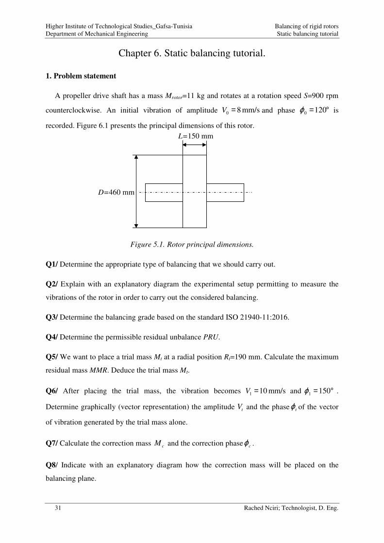
A propeller drive shaft has a mass Mrotor=11 kg and rotates at a rotation speed S=900 rpm
counterclockwise. An initial vibration of amplitude mm/s 80 =V and phase °=1200ϕ is
recorded. Figure 6.1 presents the principal dimensions of this rotor.
Figure 5.1. Rotor principal dimensions.
Q1/ Determine the appropriate type of balancing that we should carry out.
Q2/ Explain with an explanatory diagram the experimental setup permitting to measure the
vibrations of the rotor in order to carry out the considered balancing.
Q3/ Determine the balancing grade based on the standard ISO 21940-11:2016.
Q4/ Determine the permissible residual unbalance PRU.
Q5/ We want to place a trial mass Mt at a radial position Rt=190 mm. Calculate the maximum
residual mass MMR. Deduce the trial mass Mt.
Q6/ After placing the trial mass, the vibration becomes mm/s 101 =V and °= 1501ϕ .
Determine graphically (vector representation) the amplitude tV and the phase tϕ of the vector
of vibration generated by the trial mass alone.
Q7/ Calculate the correction mass cM and the correction phase cϕ .
Q8/ Indicate with an explanatory diagram how the correction mass will be placed on the
balancing plane.
L=150 mm
D=460 mm
Higher Institute of Technological Studies_Gafsa-Tunisia Balancing of rigid rotors
Department of Mechanical Engineering Static balancing tutorial
32 Rached Nciri; Technologist, D. Eng.
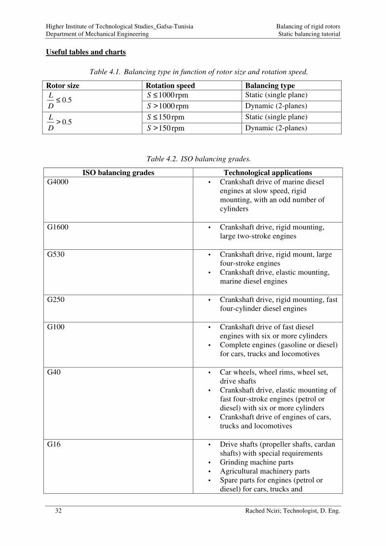
Useful tables and charts
Table 4.1. Balancing type in function of rotor size and rotation speed.
Rotor size Rotation speed Balancing type
5.0≤D
L
rpm 1000≤S Static (single plane)
rpm 1000>S Dynamic (2-planes)
5.0>D
L
rpm 150≤S Static (single plane)
rpm 150>S Dynamic (2-planes)
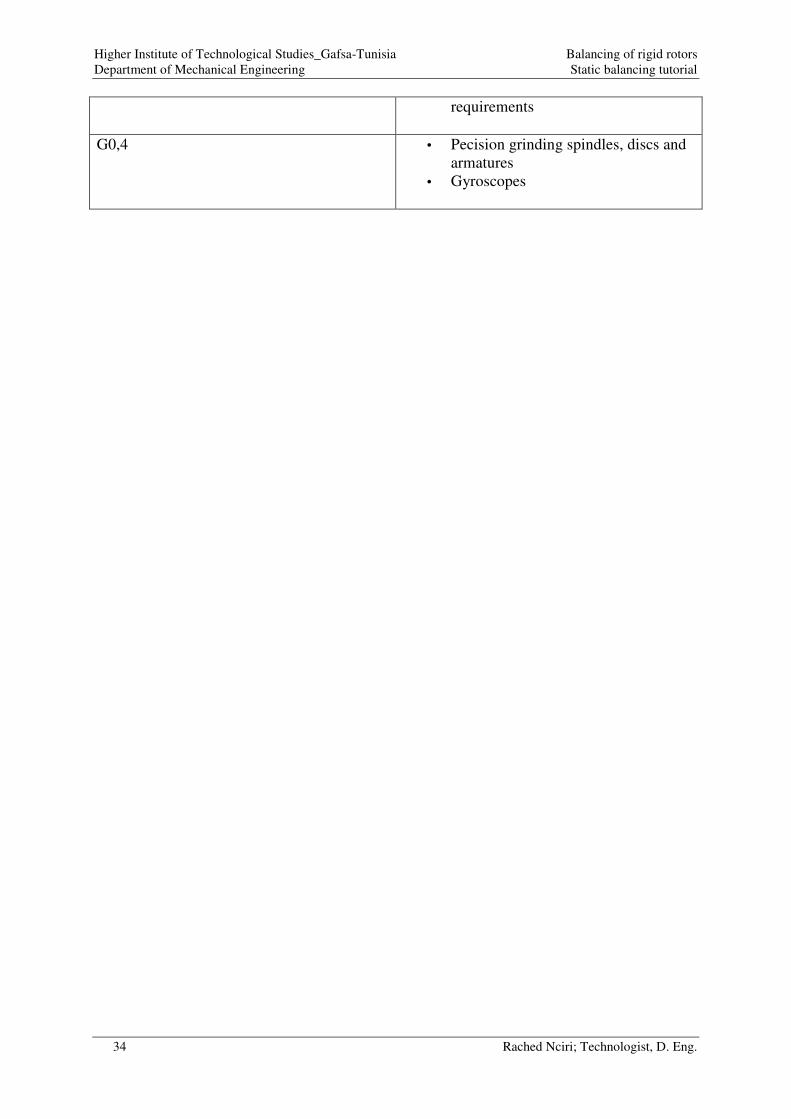
Table 4.2. ISO balancing grades.
ISO balancing grades Technological applications
G4000 • Crankshaft drive of marine diesel
engines at slow speed, rigid
mounting, with an odd number of
cylinders
G1600 • Crankshaft drive, rigid mounting,
large two-stroke engines
G530 • Crankshaft drive, rigid mount, large
four-stroke engines
• Crankshaft drive, elastic mounting,
marine diesel engines
G250 • Crankshaft drive, rigid mounting, fast
four-cylinder diesel engines
G100 • Crankshaft drive of fast diesel
engines with six or more cylinders
• Complete engines (gasoline or diesel)
for cars, trucks and locomotives
G40 • Car wheels, wheel rims, wheel set,
drive shafts
• Crankshaft drive, elastic mounting of
fast four-stroke engines (petrol or
diesel) with six or more cylinders
• Crankshaft drive of engines of cars,
trucks and locomotives
G16 • Drive shafts (propeller shafts, cardan
shafts) with special requirements
• Grinding machine parts
• Agricultural machinery parts
• Spare parts for engines (petrol or
diesel) for cars, trucks and

Higher Institute of Technological Studies_Gafsa-Tunisia Balancing of rigid rotors
Department of Mechanical Engineering Static balancing tutorial
33 Rached Nciri; Technologist, D. Eng.
locomotives
• Crankshaft drive of engines with six
or more cylinders under special
conditions
G6,3 • Parts of processing machines
• Main marine turbine gears (merchant
marine)
• Centrifugal drums
• Rolls of paper machines; printing
machine rolls
• Fans
• Assembly of rotors with gas turbines
for aeronautics
• Steering wheels
• Pump impellers
• Machine tools and common machine
parts
• Large and medium electrical
armatures (of electric motors with at
least a rod height of 80 mm) without
special requirements
• Small electrical fittings often
produced in series, for applications
insensitive to vibrations and / or with
insulating supports against vibrations
• Spare parts for engines with special
requirements
G2,5 • Gas and steam turbines including
main marine turbines (merchant
marine)
• Rigid turbogenerator rotors
• Computer memory drums and disks
• Turbochargers
• Machine tool drives
• Large and medium electrical fittings
with special requirements
• Small electrical fittings that do not
qualify for one or both of the
conditions specified for small
electrical fittings of balance quality
grade G6.3
• Turbine driven pumps
G1 • Tape and phonograph (gramophone)
training
• Grinding wheel drive
• Small electrical fittings with special
Higher Institute of Technological Studies_Gafsa-Tunisia Balancing of rigid rotors
Department of Mechanical Engineering Static balancing tutorial
34 Rached Nciri; Technologist, D. Eng.
requirements
G0,4 • Pecision grinding spindles, discs and
armatures
• Gyroscopes
Higher Institute of Technological Studies_Gafsa-Tunisia Balancing of rigid rotors
Department of Mechanical Engineering Static balancing tutorial
35 Rached Nciri; Technologist, D. Eng.
Figure 5.2. Permissible residual unbalance chart.
Higher Institute of Technological Studies_Gafsa-Tunisia Balancing of rigid rotors
Department of Mechanical Engineering Static balancing tutorial
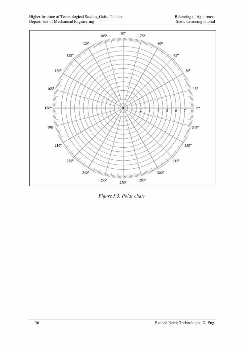
36 Rached Nciri; Technologist, D. Eng.
Figure 5.3. Polar chart.

Higher Institute of Technological Studies_Gafsa-Tunisia Balancing of rigid rotors
Department of Mechanical Engineering Static balancing tutorial
37 Rached Nciri; Technologist, D. Eng.
2. Technological answers
A1/ The appropriate type of balancing is determined based on the following methodology:
A2/ The explanatory diagram, depicted by Figure 6.4, depicts the experimental setup
permitting to measure the vibrations of the rotor in order to carry out a static balancing.
Figure 5.4. Static balancing setup.
A3/ The balancing grade is determined based on the Standard ISO 21940-11:2016 (depending
on the technological application). Our rotor is a propeller drive shaft. Based on the Table 1.1,
the grade of quality must be G16 (Drive shafts: propeller shafts, cardan shafts with special
requirements).
A4/ The permissible residual unbalance PRU is determined according to the rotation speed of
the propeller shaft, the balancing grade and based on the permissible residual unbalance chart
(Figure 6.5):
Rotor size Rotation speed Balancing type
5.0≤D
L
rpm 1000≤S Static (single plane)
rpm 1000>S Dynamic (2-planes)
5.0>D
L
rpm 150≤S Static (single plane)
rpm 150>S Dynamic (2-planes)
=
==
rpm 900
330460
150
S
.D
L
ϕ V

Higher Institute of Technological Studies_Gafsa-Tunisia Balancing of rigid rotors
Department of Mechanical Engineering Static balancing tutorial
38 Rached Nciri; Technologist, D. Eng.
Figure 5.5. Determination of the permissible residual unbalance.
180

Higher Institute of Technological Studies_Gafsa-Tunisia Balancing of rigid rotors
Department of Mechanical Engineering Static balancing tutorial
39 Rached Nciri; Technologist, D. Eng.
According to the chart, a propeller drive shaft (balancing grade G16) rotating at 900 rpm
will have a PRU in the order of 180 g.mm/kg.
A5/ The maximum residual mass MMR is calculated using the following formula:
g 42.10190
11180 =×=×= MMRR
MPRUMMR
t
rotor
Or,
MMRMMMR t ×≤≤× 105
Preferably,
g 2.10410 =×= tt MMMRM
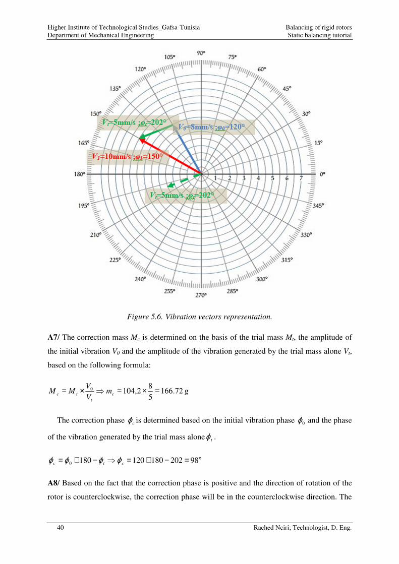
A6/ The following vibration vectors are represented on the polar chart (Figure 6.6):
• The initial vibration vector:
°==
=120
mm/s 8
0
0
0 ϕV
V
• The vibration with trial mass vector:
°==
=150
mm/s 10
1
1
1 ϕV
V
Then, we can graphically deduce the amplitude tV and the phase tϕ of the vibration vector
generated by the trial mass alone.
0101 VVVVVV tt −=+=
Based on the vector representation:
°==
=202
mm/s 5
t
t
t
VV
ϕ
Higher Institute of Technological Studies_Gafsa-Tunisia Balancing of rigid rotors
Department of Mechanical Engineering Static balancing tutorial
40 Rached Nciri; Technologist, D. Eng.
Figure 5.6. Vibration vectors representation.
A7/ The correction mass Mc is determined on the basis of the trial mass Mt, the amplitude of
the initial vibration V0 and the amplitude of the vibration generated by the trial mass alone Vt,
based on the following formula:
g 72.1665
82,1040 =×=×= c
t
tc mV
VMM
The correction phase cϕ is determined based on the initial vibration phase 0ϕ and the phase
of the vibration generated by the trial mass alone tϕ .
°=−+=−+= 982021801201800 ctc ϕϕϕϕ
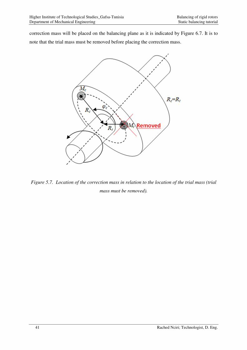
A8/ Based on the fact that the correction phase is positive and the direction of rotation of the
rotor is counterclockwise, the correction phase will be in the counterclockwise direction. The
Higher Institute of Technological Studies_Gafsa-Tunisia Balancing of rigid rotors
Department of Mechanical Engineering Static balancing tutorial
41 Rached Nciri; Technologist, D. Eng.
correction mass will be placed on the balancing plane as it is indicated by Figure 6.7. It is to
note that the trial mass must be removed before placing the correction mass.
Figure 5.7. Location of the correction mass in relation to the location of the trial mass (trial
mass must be removed).
Higher Institute of Technological Studies_Gafsa-Tunisia Balancing of rigid rotors
Department of Mechanical Engineering Dynamic balancing tutorial
42 Rached Nciri; Technologist, D. Eng.
Chapter 7. Dynamic balancing tutorial.
1. Problem statement
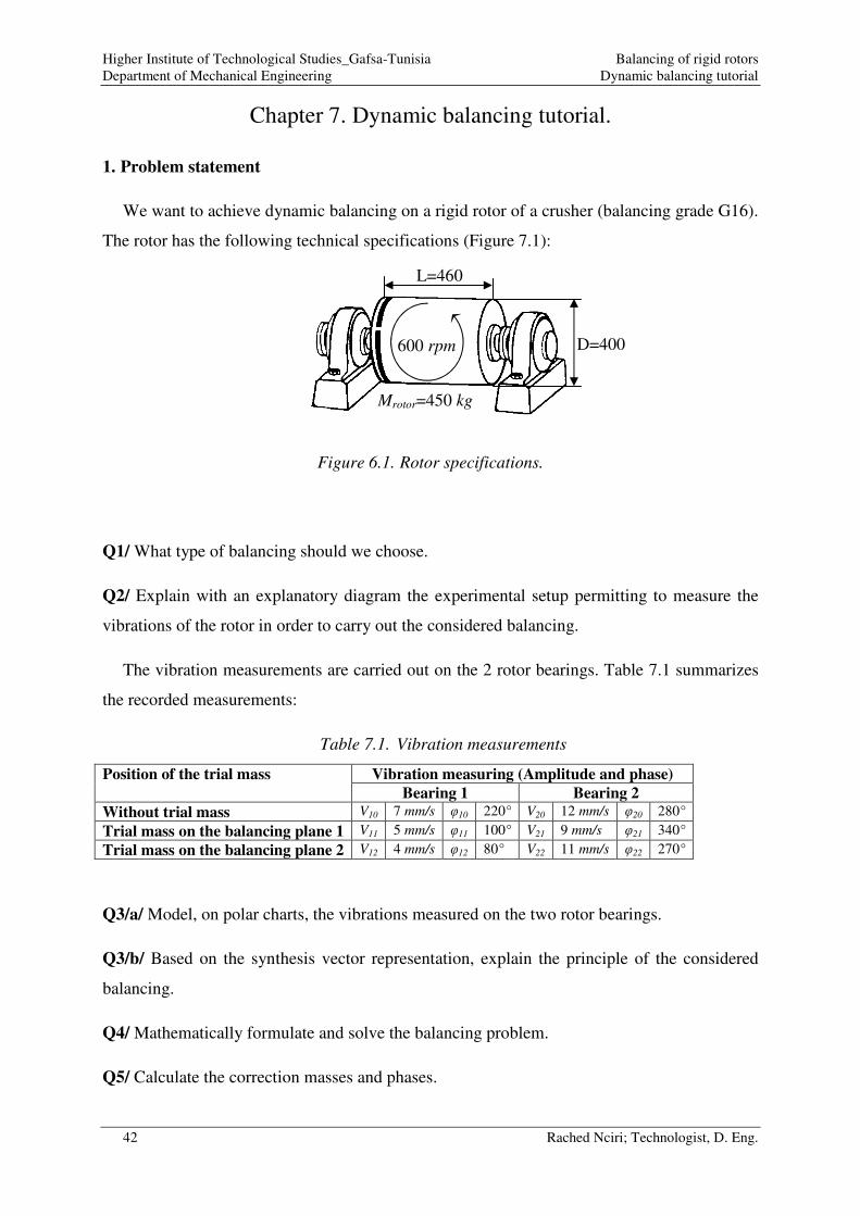
We want to achieve dynamic balancing on a rigid rotor of a crusher (balancing grade G16).
The rotor has the following technical specifications (Figure 7.1):
Figure 6.1. Rotor specifications.
Q1/ What type of balancing should we choose.
Q2/ Explain with an explanatory diagram the experimental setup permitting to measure the
vibrations of the rotor in order to carry out the considered balancing.
The vibration measurements are carried out on the 2 rotor bearings. Table 7.1 summarizes
the recorded measurements:
Table 7.1. Vibration measurements
Position of the trial mass Vibration measuring (Amplitude and phase)
Bearing 1 Bearing 2
Without trial mass V10 7 mm/s φ10 220° V20 12 mm/s φ20 280°
Trial mass on the balancing plane 1 V11 5 mm/s φ11 100° V21 9 mm/s φ21 340°
Trial mass on the balancing plane 2 V12 4 mm/s φ12 80° V22 11 mm/s φ22 270°
Q3/a/ Model, on polar charts, the vibrations measured on the two rotor bearings.
Q3/b/ Based on the synthesis vector representation, explain the principle of the considered
balancing.
Q4/ Mathematically formulate and solve the balancing problem.
Q5/ Calculate the correction masses and phases.
L=460
D=400 600 rpm
Mrotor=450 kg
Higher Institute of Technological Studies_Gafsa-Tunisia Balancing of rigid rotors
Department of Mechanical Engineering Dynamic balancing tutorial
43 Rached Nciri; Technologist, D. Eng.
2. Technological answers
A1/ The dimensional specifications give a ratio 5.015.1 >=D
L
The rotor rotates at a rotational speed rpmS 600= .
Based on the table 7.2, we opt for a dynamic balancing.
Table 7.2. Balancing type in function of rotor size and rotation speed.
Rotor size Rotation speed Balancing type
5.0≤D
L
rpm 1000≤S Static (single plane)
rpm 1000>S Dynamic (2-planes)
5.0>D
L
rpm 150≤S Static (single plane)
rpm 150>S Dynamic (2-planes)
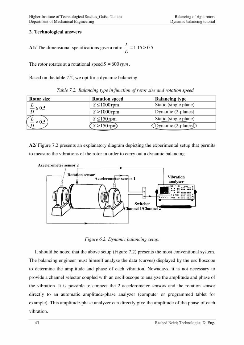
A2/ Figure 7.2 presents an explanatory diagram depicting the experimental setup that permits
to measure the vibrations of the rotor in order to carry out a dynamic balancing.
Figure 6.2. Dynamic balancing setup.
It should be noted that the above setup (Figure 7.2) presents the most conventional system.
The balancing engineer must himself analyze the data (curves) displayed by the oscilloscope
to determine the amplitude and phase of each vibration. Nowadays, it is not necessary to
provide a channel selector coupled with an oscilloscope to analyze the amplitude and phase of
the vibration. It is possible to connect the 2 accelerometer sensors and the rotation sensor
directly to an automatic amplitude-phase analyzer (computer or programmed tablet for
example). This amplitude-phase analyzer can directly give the amplitude of the phase of each
vibration.
Accelerometer sensor 2
Rotation sensor
Switcher
Channel 1/Channel 2
Vibration
analyser Accelerometer sensor 1

Higher Institute of Technological Studies_Gafsa-Tunisia Balancing of rigid rotors
Department of Mechanical Engineering Dynamic balancing tutorial
44 Rached Nciri; Technologist, D. Eng.
A3/a/ The vibrations measured on the two rotor bearings are modeled on polar charts as it is
depicted by Figure 7.3.
Bearing 1
Bearing 2
Figure 6.3. Vibrations representation on polar charts.
A3/b/ The basic idea of dynamic balancing consists in opposing the initial vibration on each
vibrating bearing by a combination of the two vibrations generated by the trial mass alone
(installed separately on the balancing planes 1 and 2). This will make it possible to neutralize
the initial vibrations.
10Vuur
11Vuur
11 10V V−uur uur
10Vuur
12Vuur
10Vuur
1mm/s 1mm/s 1mm/s
20Vuur
20Vuur
20Vuur
21Vuur
22Vuur
21 20V V−uur uur
22 20V V−uur uur
21 20V V−uur uur
22 20V V−uur uur
2mm/s 2mm/s
2mm/s
1012 VV −
11 10V V−uur uur
1012 VV −
Trial mass on the balancing plane 1 Trial mass on the balancing plane 2 Synthesis
Trial mass on the balancing plane 1 Trial mass on the balancing plane 2 Synthesis
Higher Institute of Technological Studies_Gafsa-Tunisia Balancing of rigid rotors
Department of Mechanical Engineering Dynamic balancing tutorial
45 Rached Nciri; Technologist, D. Eng.
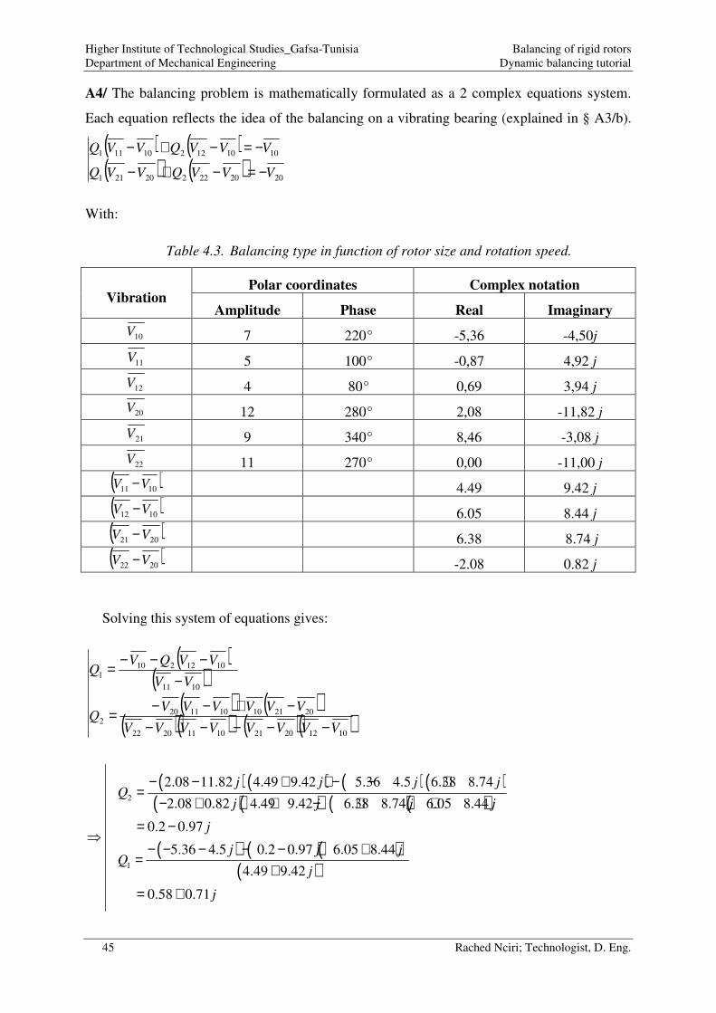
A4/ The balancing problem is mathematically formulated as a 2 complex equations system.
Each equation reflects the idea of the balancing on a vibrating bearing (explained in § A3/b).
( ) ( )( ) ( ) 202022220211
101012210111
VVVQVVQ
VVVQVVQ
−=−+−
−=−+−
With:
Table 4.3. Balancing type in function of rotor size and rotation speed.
Vibration Polar coordinates Complex notation
Amplitude Phase Real Imaginary
10V 7 220° -5,36 -4,50j
11V 5 100° -0,87 4,92 j
12V 4 80° 0,69 3,94 j
20V 12 280° 2,08 -11,82 j
21V 9 340° 8,46 -3,08 j
22V 11 270° 0,00 -11,00 j
( )1011 VV − 4.49 9.42 j
( )1012 VV − 6.05 8.44 j
( )2021 VV − 6.38 8.74 j
( )2022 VV − -2.08 0.82 j
Solving this system of equations gives:
( )( )
( ) ( )( )( ) ( )( )
1012202110112022
2021101011202
1011
10122101
VVVVVVVV
VVVVVVQ
VV
VVQVQ
−−−−−−+−−=
−−−−=
( )( ) ( )( )( )( ) ( )( )
( ) ( )( )( )
2
1
2.08 11.82 4.49 9.42 5.36 4.5 6.38 8.74
2.08 0.82 4.49 9.42 6.38 8.74 6.05 8.44
0.2 0.97
5.36 4.5 0.2 0.97 6.05 8.44
4.49 9.42
0.58 0.71
j j j jQ
j j j j
j
j j jQ
j
j
− − + + − − +=
− + + − + += −
− − − − − +=
+= +

Higher Institute of Technological Studies_Gafsa-Tunisia Balancing of rigid rotors
Department of Mechanical Engineering Dynamic balancing tutorial
46 Rached Nciri; Technologist, D. Eng.
A5/ The correction masses are calculated as follows:
tc
tc
mQm
mQm
×=
×=
22
11
However, the trial mass tm is linked to the Maximum residual mass MMR as follows:
MMRmMMR t ×≤≤× 105
Preferably:
MMRmt ×=10
The maximum residual mass MMR is calculated as follows:
t
rotor
R
MPRUMMR
×=
With;
PRU: Permissible Residual Unbalance, determined as depicted by Figure 7.4:
MMR=280gmm/kg
Rt: Arbitrary radial position of the trial mass tm on balancing planes. We choose Rt=150 mm.
kgm gMMR t 840084010840150
450280 =×==×=
( ) gmQm
gmQm
tc
tc
8319840097.02.0
7701840071.058.0
22
212
22
11
=×−+=×=
=×+=×=
The correction phases are calculated as follows:
( )
( ) °−=
−==
°=
==
35.782.0
97.0
75.5058.0
71.0
22
11
ArctgQArg
ArctgQArg
c
c
ϕ
ϕ
It should be noted that these correction masses will be placed on the same radial position
used previously for the trial mass.

Higher Institute of Technological Studies_Gafsa-Tunisia Balancing of rigid rotors
Department of Mechanical Engineering Dynamic balancing tutorial
47 Rached Nciri; Technologist, D. Eng.
Figure 6.4. Determination of permissible residual unbalance.
280