vertical vibration analysis of rigid footings
92
.."iSBH VERTICAL VIBRATION ANALYSIS OF RIGID FOOTINGS ON A SOIL LAYER WITH A RIGID BASE by MEHMET S. ASIK, B.S., M.S. A DISSERTATION IN CIVIL ENGINEERING Submitted to the Graduate Faculty of Texas Tech University in Partial Fulfillment of the Requirements for the Degree of DOCTOR OF PHILOSOPHY Approved Chairperson df the Committee Accepted Dean of the Graduate School December, 1993
-
Upload
khangminh22 -
Category
Documents
-
view
0 -
download
0
Transcript of vertical vibration analysis of rigid footings

.."iSBH
VERTICAL VIBRATION ANALYSIS OF RIGID FOOTINGS
ON A SOIL LAYER WITH A RIGID BASE
by
MEHMET S. ASIK, B.S., M.S.
A DISSERTATION
IN
CIVIL ENGINEERING
Submitted to the Graduate Faculty of Texas Tech University in
Partial Fulfillment of the Requirements for
the Degree of
DOCTOR OF PHILOSOPHY
Approved
Chairperson df the Committee
Accepted
Dean of the Graduate School
December, 1993

- ifSjl
^^^^ d ACKNOWLEDGEMENTS /UD, //O
I am deeply indebted to Dr. C.V.Girija Vallabhan, my
dissertation committee chairman, for his suggestion of the
topic and for his excellent guidance throughout this work
and Y.C Das for the valuable discussions at the beginning of
my thesis work. Also, I am grateful to the members of
my committee, Dr. Atila Ertas, Dr. William P. Vann,
Dr. Priyantha W. Jayawickrama, Dr. Partha P. Sarkar for
serving as committee members.
I would like to extend my special thanks to Dr. Jose M.
Roesset for the valuable discussion that we had in the Civil
Engineering Department at University of Texas at Austin.
I am grateful to my wife Serap Turut Asik for her
editorial comments, and her patience throughout this work.
My special thanks go to Mustafa Ulutas for allowing me
to modify his Effective Simple Numerical Integration Code
for my research.
1 1
m^M

CONTENTS
ACKNOWLEDGEMENTS ii
ABSTRACT v
LIST OF FIGURES vi
NOMENCLATURE viii
CHAPTER
I. INTRODUCTION 1
General 1
History of Studies 3
General 3
Dynamic Winkler Model 5
Wave Propagation Models: Analytical, Semi-Analytical and Numerical 11
Scope of Present Study 18
II. STRIP FOOTING ON LAYERED SOIL 21
Introduction 21
Strip Footing on a Layer 21
Formulation 21
Solution of Field Equations Given in Eq. (2.7) 26
Displacement (Compliance) Functions /j and /j 28
Forced Response of Rigid Footings 34
Numerical Results 37
An Illustrative Example of a Vibrating Strip Footing 44
Solution 46
m
^a^m-}

^ f l l T * r"'"" '"FMHlHiiiii
Strip Footing on a Non-Homogeneous Soil Medium
with Linearly Varying Modulus 4 7
Formulation and Numerical Results 4 7
III. CIRCULAR FOOTING ON LAYERED SOIL 54
Introduction 54
Circular Footing on a Layer 54
Formulation 54
Solution of Field Equations for a Circular Footing 59
Displacement (Compliance) Functions /j and /j 61
Forced Response of Rigid Circular Footings 63
Numerical Results 64
An Illustrative Example of a Vibrating
Circular Footing 70
Solution 70
Circular Footing on a Non-Homogeneous Soil
Medium with a Linearly Varying Modulus 72
IV. SUMMARY, CONCLUSIONS, AND RECOMMENDATIONS 74
Summary 74
Conclusions 75
Recommendations 77
REFERENCES 7 9
IV
MiHiii i i iHii^

••^~ - 5 « « a « B
ABSTRACT
A simple semi-analytical method is developed to compute
the response of a rigid footing subjected to a harmonic
excitation and resting on a layered soil deposit with a non-
compliant rock or rock-like material at the base. The method
is based on variational principles and minimization of
energy using Hamilton's principle. Nondimensional equations
are developed for a rigid strip and circular footings
resting on a layered soil media with constant or variable
modulus lying on a rigid rock at the base. The method is
relatively simple to use and has the ability to provide
variable elastic modulus of the soil with depth. Dynamic
response characteristics are plotted using nondimensional
parameters.
iadf^l

•'iMMPP—ii^—ii——^y- - - '-''^^mammmm
LIST OF FIGURES
1.1 Winkler Model 6
1.2 Winkler-Voigt Model 9
2.1 Soil-Footing System With Constant Shear
Modulus 22
2.2 Physical Interpretation of Foundation Impedance 2 9
2.3 Soil Reactions and Spring-Dashpot
Equivalence 31
2.4 Soil-Footing System and Soil Reactions 33
2.5 Forces and Reactions on the Soil Footing
System 36 2.6 Comparison of Results for Different Mass
Ratios 38
2.7 Vertical Decay Function (j) for Different y Values 4 0
2.8 Effect of Damping Ratio on the Response of Strip Footing 42
2.9 Effect of H/B Ratio on the Response of Strip Footing 43
2.10 Effect of Poisson's Ratio on the Response of Strip Footing 45
2.11 Soil-Footing System with Variable Shear Modulus 4 9
2.12 Vertical Decay Function (J) for Varying Shear Modulus 51
2.13 Effect of Variable Modulus on the Response of
Strip Footing 53
3.1 Soil-Circular Footing System 55
3.2 Comparison of Resonant Frequencies 65
V I
•MJiMI

3.3 Comparison of Results for Different Mass Ratios 67
3.4 Effect of Damping Ratio on the Response of Circular Footing 68
3.5 Effect of Poisson's Ratio on the Response of Circular Footing 69
3.6 Effect of Variable Modulus on the Response of Circular Footing 73
V I 1
AriMttMHtfHf^l

s^^-'^mmm^
NOMENCLATURE
dr.
a Qm
B
b
= Nondimensional frequency
= Nondimensional resonant frequency
= Half length of the footing in the x direction
= Length of the footing in the y direction (=1)
= Nondimensional mass ratio
= M](GU)Y'^^±'
H ^(t) = ^i^)^'^^ dz
e
/l,/2
F
Giz)
'H
H
h
H ji^^dz u
= Modulus of elasticity of footing
= Radius of the eccentricity
= Reissner's displacement functions
= W" 1-1
= Shear modulus of elasticity of soil
Go H
= Shear modulus of elasticity of soil at the surface
= Shear modulus of elasticity of soil at the bottom
= Depth of the soil
= Height of the footing
Vlll
ii^l

-- v^ [• mmm >/W-«V..v^V>
^b
K
K.
= Moment of inertia of footing about y-axis
= Impedance of the soil
= Static stiffness of the soil
M
H 2 ( l - v ) p /jf(|) ]Gi^fdz
i dz (l-2v)J
= Dimensionless mass r a t i o
m 2(1-V)
(l-2v)_J JGW^dx
m
H
= Jp^^^z
m.
N
= Unbalanced mass (on machine)
= Shear force at the edge
n
D O
G(^f^ ax
Pit)
Po
q(x,t)
q(x,t)
R(t)
Ro
R
T
2t
V
= Harmonic force on the footing
= Amplitude of harmonic force on the footing
= Vertical traction on the soil surface
= External applied force
= Total soil reaction
= Amplitude of total soil reaction
= Radius of the circular footing
= Kinetic energy in the soil-footing system
H
= JG<l)'rfz
= Potential energy in the soil-footing system
I X
MOUHMli?]

"l^-^^^^'^flKm^ •^m.
w
w w
a
= Shear wave velocity of soil
= Vertical displacement at a point in the soil
= Surface disturbance
= Amplitude of the displacement under footing
'2(1-v)c, 1 - f l n
{l-2v) c,{H/Bf '
Material damping
= Variational notation
= Normal strain in the x direction
= Normal strain in the z direction
= Vertical decay function
1-2VA 2(1-V) B
a l + 2a
•fln
Y^ = Shear strain
V = Poisson's ratio
p^ = Mass density of footing
p = Mass density of soil
o = Normal stress in the x direction
a = Normal stress in the z direction
T = Shear stress
Q = Operational frequency of machine
X
iMMMHliit^

" ' • " • '•*•-*
CHAPTER I
INTRODUCTION
General
The design of foundations to resist dynamic loading,
either from supporting machinery or external sources, has
been a major topic of research and study for the last thirty
years. In particular, the dynamic analysis of machine
foundations is made to study the vibration of a soil-
foundation system subjected to some frequencies and
amplitudes such that operating machines supported by the
foundation or machines in the immediate vicinity of the
foundation are not subjected to severe amplitudes of
vibrations during their normal operations and, besides,
people around these machines are not disturbed. Then, the
determination of amplitudes and frequencies for performance
criteria related to performance of foundations is an
important step. A design engineer can only accomplish this
by choosing an appropriate analysis technique to be applied,
if it is available. Even though numerous analysis techniques
have been developed for such machine foundation systems, the
design engineer is still confronted with a complicated
design procedure, where he has to deal with oversimplified
soil parameters.
Sij-j^a,i^tmmititm ^M^uidMidiHBMiii»;^^^^^^^^^^MBd^^^BS

smiMKJi.i .- i-i-iwi'mw,'"?i^^
If examined, one can easily understand what a complex
phenomenon the vibration of a footing on a soil medium is.
The dynamic analysis of the system needs wide knowledge of
soil and structural dynamics, wave propagation and soil
properties, which are separate disciplines in engineering
that need to be combined.
Soil-foundation systems can be classified according to
the material and geometric characteristics of the footing
and the soil underneath. Therefore, a soil-foundation system
can be identified by its shape such as strip, circular,
rectangular or arbitrary; amount of embedment such as on the
surface, embedded or placed deep into the soil; the type of
soil profile such as layered medium on rock, layered medium
on a half space or a deep uniform medium; and the footing
flexural rigidity such as flexible or rigid footing. To
analyze the vibration of the footing, an analysis method
based on material and geometric characteristics of the soil-
foundation system should be selected.
The most important problem in the analysis of footings
is to predict the frequency of the footing by determining
impedance and inertia characteristics of the overall medium
and the amplitude of the footing by determining damping
characteristics (geometric and material damping) of the soil
medium. The Raleigh waves carry away 67% of the energy
(Fung, 1965). Then these types of surface waves cause the
radiation damping which plays an important role in the
mtmmmmtm

amplitude of the footing, especially with regard to layered
soil on rock.
History of Studies
General
Before any method of analysis was developed, machine
foundations were designed by the rule of thumb. For example,
to be sure about the safe design, one had to build a massive
foundation. In this case, the total weight of foundation was
equal to three to five times the weight of the supported
machine. By doing this, the resonant frequency of the system
was being decreased due to the increase in mass of the
foundation.
In the 1930's, as a result of tests done by German
DEGEBO (Richart et al. , 1970), valuable information was
obtained to develop some empirical analysis procedures.
These procedures were used until the 1950's. The important
aspect in these methods was the attempt of the researchers
to find the resonant frequency of the system by defining
"in-phase mass" and "reduced natural frequency" concepts.
In the "in-phase mass" concept, some empirical soil mass
was being added to the footing mass to more closely get the
resonant frequency of the system. Actually, this added "in-
phase mass" represents the inertia of the soil, since the
inertia forces developed in the soil have an effect on the
ttmrnm

mm lM^'^f:^i
resonant frequency through dynamic interaction. Of course,
this was not what the researchers had in mind.
The other method, which is called the "reduced natural
frequency" method was developed for the same purpose as the
"in-phase mass" method. Because of the inertia of the soil,
the natural frequency of the footing decreases. The early
researchers thought that the natural frequency of the system
was a function of or was affected by the contact area,
contact pressure and the properties of the underlying
medium. They tried to incorporate the above effects by
multiplying the natural frequency of the system with the
square-root of the average vertical contact pressure. This
method is also known as the Tschebotarioff's "reduced
natural frequency" method (Gazetas, 1983).
The early methods, stated above, were only concerned
with the resonant frequency of the system. They were not
able to predict the amplitude of vibration at the operating
or resonant frequency.
If one looks at the historical development of the
methods of analysis for footing vibrations, it can be
observed that there are two main schools of thought which
were developed parallel to, but at the same time almost
independent of each other until recent years. One replaces
the effect of the underlying medium or soil with a spring or
a bed of springs without considering dynamic interaction and
this concept originated from the classical Winkler model
HMMMHIiltf^

iiMimmi.ui....ii!,.... L, 4
used for the analysis of elastic foundations. The Winkler
method developed in 18 67 is also known as "elastic subgrade
hypothesis" (see Fig. 1.1). The other is the wave
propagation modeling that inherently considers a dynamic
interaction between the footing and the soil, and originated
from the study of the vibration of an elastic semi-infinite
medium (half-space) by Lamb (1904) for vertical harmonic
line loading. Each school of thought will be discussed under
a separate heading.
Dynamic Winkler Model
The Winkler Model is a very popular method to model
footings resting on a semi-infinite medium. Winkler first
introduced this method in 18 67 in the analysis of rail-road
tracks resting on soil as a static problem. He was very
successful because of the physical appropriateness of the
problem. His model replaces the soil medium by vertical
independent springs which only represent elastic behavior of
soil or stiffness of the soil as a more specific term. In
the equilibrium of forces in the vertical direction, inertia
forces can be easily introduced to solve the problem
dynamically. This is known as the Dynamic Winkler Model. The
most important simulation failures of this model are: lack
of the representation of continuity of the medium, ignoring
the damping of the medium because of geometry, and lack of
B -m • i t i i ia i i i ia i l l l l i i i i iMl^

Bf •PPPmiiPPVMi>«">"*""'^>*>wK>*«iaM
P(t)
k< k< k < k<: k< k<: k< k < k
Fig. 1.1 Winkler Model
irli^iMliiilMiiii*»r

ff^ffl
consideration of dynamic interaction between the soil and
the footing. Despite its inherent inadequacies, it is still
in use among many engineers for the analysis of both static
and dynamic problems. Its attractiveness arises from the
very simple form of the equations. Also, the value of the
spring constant, k, is being determined more accurately
because of the availability of reliable data from field
experiments done with the sophisticated instruments
available at present.
During the 1960s, Barkan (1962) conducted some plate
bearing tests in the field to get the spring constant k.
From these tests, he has prepared tables and empirical
formulae to easily estimate design values of the subgrade
reaction for several types of soil for each possible mode of
vibration. The Winkler model with k from plate bearing tests
can give reasonable information about the response of a
foundation in the low-frequency range. By ignoring geometric
damping, the results obtained by this method around the
resonant frequency may not be accurate. But this model was
the one which was used for the design of machine foundations
in India and it was incorporated as a design procedure into
the 197 0 "Indian Standard Code of Practice for Design of
Machine Foundations" (Prakash, 1981). There is no doubt that
results are conservative and provide reasonable estimation
of the resonant frequency. But the designer has to notice
that in case of high damping, the resonant frequency of the
aaaiifadta mmgmmtfiig^

•gi—ggBW . • ..jj^^^gwawjtf*^ '"^'^'^^^^^''"""^""^'"^^^ff^^^gB^^^S ??r<rrt*s^' -•;—
8
system will be importantly affected and amplitudes will
drastically decrease. Therefore, for some modes of
vibration, the designer may end up with highly conservative
results. For the rotational modes of vibration, the designer
can even end up with unsafe designs (Gazetas, 1983).
Amplitudes of vibrations are directly related to the
dissipation of the energy from the system. To simulate this
energy dissipation, viscous dampers can be added to the
system parallel to the elastic springs (see Fig. 1.2). This
procedure is called the "Winkler-Voigt" model and the 1971
USSR machine foundation code is based on this model (Barkan
and Ilyichev, 1977). Dynamic tests are made to determine the
dashpot constant. From these tests, it is observed that
there is a discrepancy between the spring constants obtained
from dynamic and static repeated loading tests. Barkan
introduced an in-phase soil mass to polish this discrepancy
regarding the size of foundation, properties of the medium,
mode of vibration, etc.
The Winkler and Winkler-Voigt models are both completely
empirical. In static analysis, the Winkler model is known as
a one-parameter model regarding the spring constant, k.
Developments have been made by many researchers to improve
the Winkler model by adding one more parameter to describe
the soil. But these developments were limited to static
analysis only. In 1954, Pasternak developed a two-parameter
model regarding a parameter, s, for the shear layer in
mm

•pi^^Hm^^^^—".—™^^"^^liW»^«llBijJi«i«iil I i.,.~,v.
P(t)
7777
cLiJ k CL±i
7777
Fig. 1.2 Winkler-Voigt Model
ifliiiiiMMilfl

fS""^
10
addition to the spring constant, k. Vlasov and Leont'ev
(1966) derived formulae which relate Pasternak parameters to
the subgrade displacement profile by recoursing to a virtual
work principle. Vallabhan and Das (1991) developed a new
model that is mathematically consistent in determining the
so-called "y" parameter and named their model the "Modified
Vlasov Model." All of their studies are about static
analysis (Vallabhan and Das, 1988a, 1988b, 1991). For
dynamic analysis, Baranov (1967) developed a model by
utilizing the wave propagation concept to define the
behavior of the system. He utilized wave equation solutions
for simplified conditions. His improvement was the
integration of an internal coupling mechanism by connecting
the vertical thin soil strips with horizontal springs which
work horizontally and vertically because of the displacement
differences in adjacent strips. Nogami (198 9) utilized the
two-parameter model concept. He improved the Pasternak model
by adding more shear layers which are connected to each
other by vertical springs. In his derivation of related
equations, he used the energy principle. In another study,
Nogami and Leung, (1990) improved Baranov's approach, which
is based on a Winkler approximation.
IMHUMlilPI

11
Wave Propagation Models: Analytical. Semi-Analytical and Numerical
The reason for calling the following models "wave
propagation models" is that they consider the propagation of
stress waves in a semi-infinite or even finite soil medium,
and the dependence of the stress wave propagation on the
solution of the dynamic behavior of the footing. The
origination of this model should be credited to the
classical solution by Lamb (1904).
Since Lamb's work is the cornerstone for the development
of these wave propagation models, any student studying the
theory should start from his solution. Lamb first studied
the response of the elastic half space subjected to
oscillating vertical forces acting along a line. Thus, he
solved the two-dimensional wave propagation problem. He
repeated his work for horizontal forces and forces inside or
on the surface of the medium. Later he solved the three-
dimensional case in which a single concentrated dynamic load
is acting on the surface of a body, and the problem was
called the "Dynamic Boussinesq Problem." This solution
formed the basis for the study of oscillation of footings
resting on a surface of half-space (Reissner, 1936; Sung,
1953; Quinlan, 1953; Richart et al., 1970).
In 1936, Reissner (1936) developed the first analytical
solution for the vertically loaded cylindrical disk on an
elastic half-space. His solution is considered to be the
first engineering model. He reached a solution by

^^^^^^n •••"'• ' ^ " ' ^
12
integrating Lamb's solution over a circular area for the
center displacement, ZQ;
^ Pr,Exp(i(£i) , ^
Gi 0
where,
Po= amplitude of the vertical force,
G= shear modulus of the medium,
ro= radius of the circular disk,
f\Si~ Reissner's displacement functions.
His solution was approximate because he assumed a state
of uniform stress under the footing which provided
mathematical simplicity in the solution of the problem. His
important contribution is that his work shed light on
radiation damping that had not been realized until then.
During the dynamic interaction, stress waves originating
from the contact surface propagate through the medium as
body and surface waves. These waves carry energy away from
the footing and this causes a significant drop in the
amplitude of vibration as a result of energy dissipation.
This reduction was realized as "geometric damping" in later
years.
The assumption of a uniform stress distribution is
unrealistic for many foundations. During the mid-1950s,
Quinlan (1953) derived equations for parabolic, uniform and
rigid base stress distributions. He introduced the solution
for only rigid base stress distribution. In the same year
^^^^^m\

wm VHP ii^gH^^S^.
13
Sung (1953) also set up equations for three different stress
distributions and presented solutions for all cases. The
studies of Quinlan and Sung were an extension of Reissner's
solution. The approximated stress distributions used by Sung
(1953) under the footing are as follows:
(1) Uniform approximation:
a. = P^Expiiayt)
7cr'
0 = 0
for r <r^
for /')ro;
(2) Parabolic approximation:
G. = PoExpiioyt)
nr^
a =0
for r<r.
for r)rQ;
(3) Rigid base approximation:
a, = P^ExpiiCiyt)
2nro4ro ' r'
a.=0
for r<j'r
for r>/o
In these solutions, the displacement is described at the
center of the circular disk. The parabolic and uniform
stress distributions produce larger displacements at the
center than at the edge, which correspond to the
displacement pattern of the flexible footings. The rigid
base stress distribution produces a uniform displacement
pattern under the footing. Quinlan's and Sung's results are
valid both for circular and rectangular footings lying on an
elastic half space.
^SSiSSS^mBaaM^

' fl^fTPsn^l mmmk^'^^-^F^
14
Other approximate solutions were found by Arnold,
Bycroft and Warburton who assumed a static stress
distribution under the footing. Arnold (Arnold et al., 1955)
studied the vibration of circular footings for four modes of
vibration, which are horizontal, vertical, rocking, and
rotational. Bycroft (1956) and Warburton (1957) presented
similar studies. Bycroft was the first who presented the
solution for vibration of a footing on a layered medium.
Most of the researchers who deal with this problem today
know that the stress distribution under the footing changes
with the frequency of vibration. With a static stress
distribution the resonant frequency obtained becomes higher
than the actual resonant frequency.
The aforementioned solutions depend on the assumption of
the stress distribution under the footing. In reality, the
problem is a mixed boundary-value problem, which means the
described pattern of the displacement is imposed under the
footing and zero stresses on the rest of the area. By
considering the above boundary conditions and ignoring
secondary contact stresses (relaxed boundary) under the
footing for the sake of simplicity, researchers started to
solve the footing vibration problems in a more realistic
way. Awojobi and Grootenhuis (1965) presented a solution for
strip and circular footings on an elastic half space. In
1965, in his doctoral thesis, Lysmer (1965) studied the
vertical vibration of circular footings by discretizing the
•MM m^.

circular area into concentric rings, each having a frequency
dependent uniform stress distribution. His model was
consistent with the boundary conditions. By modifying
Reissner's solution, Hsieh (1962) was the first who showed
that a footing lying on an elastic medium can be represented
as a single degree of freedom system. Later, Lysmer
introduced a frequency independent stiffness coefficient,
K^, and dashpot coefficient, C^, for the medium vibrating in
the low frequency range. For low frequencies, the footing
resting on a semi-infinite medium is treated as a single
degree of freedom mass-spring-dashpot system, which is known
as Lysmer's analog. As a result of his studies, K^ and C^
are defined for low frequencies as follows:
K,= AGR l-\)
and C„ = 3AR^ 1-0)
V ^ where G is the shear modulus of soil, R is the radius of the
circular footing, V is Poisson's ratio of the half-space,
and p is the soil density.
After Lysmer, similar studies were done by Hall (1967)
and Richart and Withman (1967) for other modes of vibration.
In their studies, they could not find good agreement between
the resonant frequency of the actual system and the simple
Lysmer mass-spring-dashpot system. Thus they suggested that
a fictitious soil mass be added to the foundation mass for
each mode as shown in Table 1.1
•..:AI UUdftdiyi l i^

m am q m ^^^s^^^sm
16 Table 1.1 Equivalent lumped parameters for analysis of
circular foundations on elastic half space
S t i f f n e s s K
Mass r a t i o m
Damping r a t i o
F i c t i t i o u s a d d e d mass
Mode V e r t i c a l
4GR
1-1)
m( l - 'u )
4pR'
0.425
0.27m
m
H o r i z o n t a l
8G/?
2-1)
m(2-D)
8p/?'
0.29
0.095m
m
R o c k i n g
8Gi?'
3(1-D)
3 / , ( l -D)
8pi?'
0.15
(l + m)m'^^
0.247,
Tn
T o r s i o n
16GR'
3
7.
0.5
H-2m
0.247,
m
1^,1, = mass moment of inertia around a horizontal and vertical axis,
respectively; Damping ratio =C/C^ where C^=2(/s:w)'" or C^=2{Kiy" for
transiational or rotational modes of vibration, with / = / or 7 for
rocking or torsion, respectively.
In addition to the aforementioned studies, Luco and
Westman (1971), Karasudhi et al. 1968 and Veletsos and Wei
(1971) spent considerable effort to obtain impedance
functions for strip, circular and rectangular footings on a
half space by considering the problem as a mixed boundary
value problem. During the mid seventies, Luco (1974) and
Gazetas (1975) developed analytical solutions for the same
type of footings on the surface of a layered medium with
rigid rock as the last layer or a layered medium lying on a
half space. Further, they continued studies on the vibration
of footings (Gazetas and Roesset, 1976, 1979). These results
were not only about extreme cases of a layer on rigid rock
m

ne ^^mamm^^--
17
and half space, but also about a layer on rock with a finite
rigidity. Gazetas and Dobry (Gazetas et al., 1991a, 1987a,
1987b, 1985, and Dobry et al., 1984a, 1984b, 1985) have done
more work on the stiffness and damping of arbitrarily shaped
foundation. They have published many useful charts, tables
and graphs that assist engineers to design practical
footings subjected to vibration.
As has been happening in all areas of engineering, the
use of digital computers with large storage memory has
boosted different approaches in footing vibration research.
The derivation of dynamic finite element formulations and
the introduction of viscous and consisting boundaries made
it possible to simulate infinite media reasonably and to
analyze any kind of foundation (on the surface, embedded or
having arbitrary shape, etc.). Some problems, which formerly
could not possibly to be solved analytically because of
complex geometry, have been handled easily by this method.
It helped to verify and calibrate analytical solutions. In
spite of its versatility, the finite element method is too
complex and requires too much memory and computation time on
the computer in solving three-dimensional problems.
Researchers have used the finite element method effectively
to solve two-dimensional problems in plane strain and in
axisymmetric cases even with nonlinear properties of the
medium.
— — ' " " • ' " " miM

lfE5!! TSSTf-nTS
During the last two decades, a new method called the
Boundary Element Method (BEM) has been employed for a wide
class of engineering problems. The most important advantage
of this method is that it is possible to reduce the
dimensionality of the problem by one, and it requires
discretization only on the boundary instead of the whole
domain. This technique allows a considerable saving of
memory on the computer. First, Dominguez and Roesset (1978)
solved the dynamic response of rigid foundation by the BEM
in the frequency domain. After that, the BEM was used by
Spyrakos and Beskos (198 6a, 198 6b) to solve the dynamic
field equations for two-dimensional rigid and flexible
foundations and to find the compliance functions for a rigid
strip footing on a viscoelastic soil, etc. In the paper
written by Ismail and Ahmad (1989), the dynamic response of
rigid strip foundations on a viscoelastic soil subjected to
vertical excitation was investigated in detail for three
types of soil profiles, namely, a homogeneous half space, a
stratum-over-half space and a stratum-over-bed rock.
Scope of the Present Study
Previous studies had done little on the vibration of the
surface strip and circular footings on layered media. In
this study, a very simple new model is introduced to solve
the problem of vibration of footings on layered media. The
Medium can be a single soil layer with constant modulus
^ ^ iBSB^i^tiiy^l

'J.._iJlU-!«
iim-nwiM -as i:i.iti±fir3L---w..5»*.-J5fca*t-»'
19
along the depth or a layer with a variable modulus along the
depth as an approximation to a multi-layered medium.
Chapter II is devoted to strip footings resting on an
elastic soil layer, with constant or variable modulus, which
in turn rests on the rigid rock or rock-like material. The
soil is infinite (i.e., there is an open boundary) in the
horizontal direction. The governing differential equations
are derived using variational principles and Hamilton's
approach, and these equations are in coupled form. An
iterative numerical procedure is applied to solve these
coupled equations. In the variable modulus case, due to the
complexity of the differential equation for a decay
function, (j), in the vertical direction, the finite
difference method is employed to solve the related
differential equation. Also, a tri-diagonal matrix solver is
employed to take advantage of lesser storage. Even very
small PC's can be used to solve the above problem by the
computer program written for the new model. Results are
compared with the available published data to verify the
present results for rigid strip footings resting on a layer
underlain by rigid rock.
Equations for a circular footing resting on a layer with
constant modulus and on a layer with a variable modulus are
derived in Chapter III. The procedure used for the strip
footing is followed for the circular footing, too. The
solution to the differential equation of a surface
^a ms^^mtim

•II f l - - ^
20
disturbance for circular footing is a Modified Bessel
Function and numerical values of the Bessel Function are
included in the program. An iterative procedure is applied
to determine the parameters which depend on the
nondimensional frequency, a^. In order to achieve
verification of the model, a comparison is done with the
available published data for a rigid circular footing
resting on a layer underlain by rigid rock.
-•aH^BBBBBi tf^l

^S^^^^^^^V* - .a w?aW5Kfv7^*«jrB»p g^UJfflMUIiWWWIillil Ill I I iiiiiiiillli IIIMIIilll
CHAPTER II
STRIP FOOTING ON LAYERED SOIL
Introduction
As it is known, footings are generally placed on a semi-
infinite soil medium which is layered, and they are usually
embedded and resting on a rigid base. But, in this study
footings placed on the surface are studied. For small
deformations, the soil can be assumed as elastic and linear.
If the soil is stratified, the modulus of elasticity of the
soil is variable. Such a problem is too complicated and
engineers use an approximation for the continuum using an
average modulus of elasticity for the soil. An idealization
of this type of continuum can be represented as shown in
Fig. 2.1. In the model developed here, it is possible to
incorporate a variable modulus of elasticity of the soil
with respect to depth. The modification required for this
analysis will be discussed later in this chapter.
Strip Footing on a Layer
Formulation
To derive the governing differential equations for the
present model, Hamilton's principle is the perfect
mathematical tool. The principle is
b\'\T-V)dt = 0 (2.1)
21
^

ip^^ m^^mmn^mmK
22
_ ^
Surface
2B \1 \
V S o i l
Medium Ps . G , V
//////// v/////////////////////////////y Rigid Bedrock
>x
77777
F i g . 2 . 1 S o i l - F o o t i n g System wi th Constant Shear Modulus

mgm» i|u .^L^iim^itygggEggs.
23
where, T is the kinetic energy of the footing and soil, and
V is the potential energy of the footing and soil. By
assuming that the footing and soil experience only vertical
vibration (i.e., M(x,j,z,r) = 0 in the soil), the kinetic energy
in the system can be written as follows;
=irj:M<?» -ii>j> (?) ^ ' (2.2)
where.
W{x,z,t)= vertical displacement of a point {x,z) in the soil,
W{x,0,t)-W{x,t)= vertical displacement of the footing,
p = density of the footing,
p = density of the soil,
jb= width of the footing (=1 in plain strain case) ,
B= half length of the footing (in the x direction),
h= height of the footing (in the z direction),
H= depth of the soil layer.
The total potential energy, V, in the soil and footing is
written as follows;
V = V -\-V . ^ ^bending ~ ^soil
av. H
- e e O
= \\\E,z\—Yfdzdx^^\\{a^z,+QX,+i:^Udzdx -BO ^^
B
-bjqix,t)W{x,t)dx
( 2 . 3 )
-B
where, E^= the modulus of e l a s t i c i t y of the footing.
ttlUMi^
mmfi'^f^ -JS-iSi
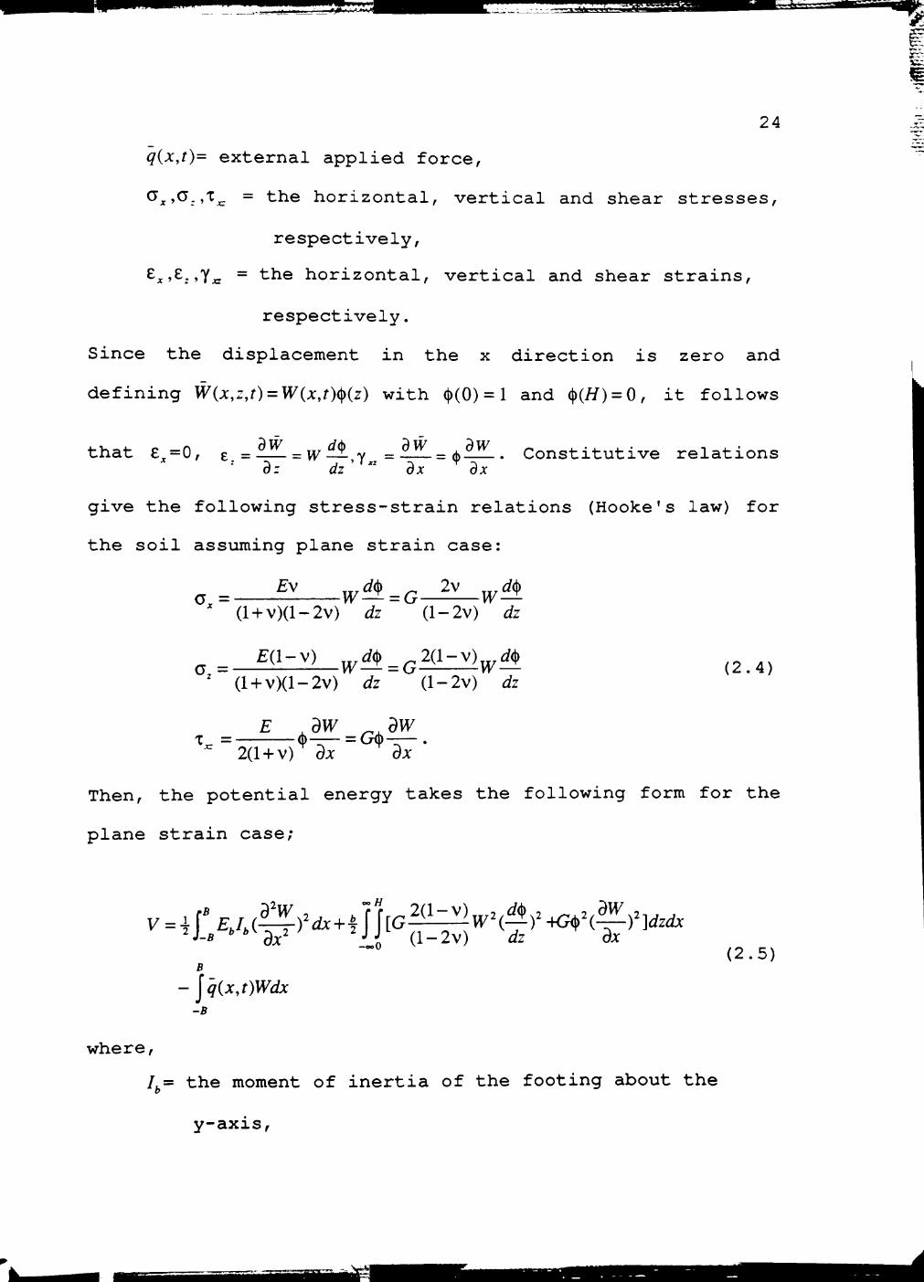
24
q{x,t)= external applied force,
^x^^:^'^xz - the horizontal, vertical and shear stresses,
respectively,
;t' 2'Y« ~ "th® horizontal, vertical and shear strains,
respectively.
Since the displacement in the x direction is zero and
defining W{x,z,t) = W{x,t)(^{z) with (|)(0) = 1 and (1)(77) = 0, it follows
that e^=0, ^ = ^ = w^ y =il^=(t)^. Constitutive relations
give the following stress-strain relations (Hooke's law) for
the soil assuming plane strain case:
' (l + v)(l-2v) dz (l-2v) dz
^ ^ Eil-v) ^^,#_^2(l-v)^^,#
' (l + v)(l-2v) dz (l-2v) dz (2.4)
(j)-_ = G(j)— '" 2(1 +V)' dx
Then, the potential energy takes the following form for the
plane strain case;
V = dw
B
- jq{x,t)Wdx -B
where.
(2.5)
1= the moment of inertia of the footing about the
y-axis,

-.-^*lii >.v.iM.w.:..V^ ^ - .11. 1 ilj J.l*MUiU^a
25
G= the modulus of elasticity of the soil,
v= Poisson's ratio of the soil.
Equation (2.5) is applicable to a footing which can have
some flexibility, such as bending in x-z plane. But in this
study, the footing is assumed to be rigid and thus, the
first term in equation is equal to zero. And the derivatives
of W under the footing with respect to x are zero.
After applying variational principle in Eqs. (2.1), (2.2)
and (2.5) and taking the variation in W and (}), the
following field equations and boundary conditions are
obtained:
1. For -B<x<B (soil surface under the footing) with bW^O
{pj.h + m)W+kW = q
with boundary conditions,
2t-z—^W = 0 ; dx -^
2. For x<-B&x>B (soil surface outside the footing)
mW-2t^ + kW=0 dx^
with boundary conditions,
2,^61^-^=0 and 2r^6l^|>0; a : - dx *
3. For 0<z<H (inside the soil) and ^^0
dz^ H
with boundary conditions.
(2.6)
(2.7)
(2.8)
%~s.Mi-

f^WBPKW- l-U IJW.' 4JUI1 I. .!•-;• g x j ^ j ^ . l
S B •J'.'V.«JIH,<.(..VS. .VMUHU '-tvr^^v^t"'i~
m—6(j) dz
H
= 0 ;
where.
//
m = jp>^^z = p 77c,
(l-2v)J dz (l-2v)77
w 2r = jG(l)'^z = G77c,
where c^ and c, a r e r ede f ined as
and
c.=//}(J)Vz , c,=-ifj<t,^& 0 J
26
m = 2(1-V)
(l-2v)
OO
^GW^dx
n=]G{^fdx •' dx
H m
Solution of Field Equations Given in Eq.(2.7)
Equation (2.7) is a homogeneous equation. If the system
is linear and the footing is subjected to a harmonic force
with a frequency Q, the response of the system is also

^ ^ • ^ -ffWS^ffWBWI^Hroffrtifriioriiiniiii • IIIr • I. Min' n
27
harmonic with the same frequency in a steady state
condition. It is assumed that,
W{x,t) = wix)e'''' and 1 =-QV(A-)e'"'.
Then equation (2.7) takes the following form:
aV k-mQ.^^ —i--( 1 )w=0. dx' 2t
(2.9)
The solution to this differential equation is a
X w{x) = C,e * +C2^^
.a.2 k-mQ^ where, (—) = . Applying the boundary condition at .x = oo,
B 2t
for a finite value of displacement, C2 = 0 and at x = B, for
the rigid body displacement of the footing Vr = Ho (at the
surface of the soil under the footing), C^^W^e^^. Then, for the vibration of the surface of the soil outside the
footing, the solution is as follows:
B<X<oo
-oo<X<-B .
--(x-B) .„
W{x,t) = W.e^ e'""
-{x+B) ._,,
W{x,t) = W^e^ e'"' (2.10)
Similarly, the differential equation (2.8) has the
following solution after application of the boundary
conditions (t)(z) = l at z = 0 and <j)(z) = 0 at z = 77;
(j>(z) = 1
l-e 2Y
1-z -^z (2.11)
^11 iipi^if 11 II' ^ssssam^^i

•J.S."KI.V..'.ai5;V Mfajmy.ijtrT
28
Displacement (Compliance) Functions / and /.
Although the topic of this section is displacement
(compliance) functions, it is better to start with the word
"impedance" as the physical interpretation of impedance is
easy, and the displacement function (compliance) and
impedance (stiffness) function are reciprocal to each other.
Figure 2.2 introduces the physical interpretation of the
impedance function. Impedance is defined as the ratio
between the force R{t) and the steady-state displacement W
at the centroid of the base of the massless foundation and
is a function of frequency (Gazetas, 1987b) . Then the
vertical impedance is defined by
Wit)
and, therefore the compliance function is
(2.12)
(2.13)
As may be seen in Equations (2.12) and (2.13), the impedance
and compliance functions are both complex functions since
the energy given into the system is not conserved. Part of
the energy dissipates through the relative motion between
soil particles and pore fluid (viscous nature) or the
irreversible sliding between soil particles (hysteretic
nature) or both, which is called material damping (Kausel,
1974). Energy also dissipates through the infinite medium as
the elastic stress waves propagate to infinity. This loss of
abyfiiiMiiiiiMBiliHaHp

.-™-iAaaaancis::^- i9r<3.v.«w.w.:.V\ I' MK^MJi' \.ifm.'.i JJKAsmim
29
t R(t)
Rigid and massless
W=-R(t)
Fig. 2.2 Physical Interpretation of Foundation Impedance
BiBifiiMi&

Eli...,J*.^J.UWI •j^sm^B^Biam f " t,™- T ! I ' ^ | W»MttaK'H*v.
30
energy is called geometric damping or radiation damping
(Gazetas, 1987b). In Equation (2.13), /j represents energy
conserved in the system (or the recoverable component of the
deformation) and f^ represents energy dissipated in the
system.
For a massless rigid footing, the displacement under the
footing at time t is W = WQ which is a constant. Thus, Eq.
(2.6) takes the following form:
mW+kW = q (2.14)
where, W stands for the second derivative of W with
respect to time and q is the vertical traction on the soil
surface. Figure 2.3 is a mathematical model in which the
soil medium is replaced by forces and edge reactions. Using
Fig. 2.3, the equilibrium of forces can be written as:
2Bq + 2N = Rit) (2.15)
where R = RQe'^ is a line harmonic force per unit length of
the strip footing and R^ is the amplitude of this force. In
Eq. (2.15), N represents the effect of the continuous
medium on both edges of the footing. As a result of the
variational formulation,
N = 2t dw dx
( 2 . 1 6 ) t=±fi
dw 1 dw and in wave p r o p a g a t i o n , we know t h a t ~^~ = ~~^ (Lysmer and
ox V^ ot
Kuhlemeyer, 1969; Gazetas, 1987b), where V^ is the shear
ma

mtmmtmmmi
31
y \ A A A A A A A A A A A A A A A A
N
R(t)
N
Above figure is equivalent to following
R(t)
/TTZ /Tzr
Fig.2.3 Soil Reactions and Spring-Dashpot Equivalence

ill,..^u.^..>, ..-^'-^ ^ ^ s ^ ^ ^ ^
wave velocity. Substituting dw ~d^
32
and 2t in equation (2.16), A'
takes the following form:
N = iG{H IB)c,a,W,e"" = N.e'"" (2.17)
I f ? 2 where c, = — J ^ dz and flp = V.
is the nondimensional
frequency. In Fig. 2.4, N^ is the lumped form of all the
shear stresses along the depth at x=B at time t. It is
assumed that these stresses are taking energy away from the
system. Therefore, A represents a shear force which will be
propagated out to infinity because of the geometry of the
problem which causes geometric damping or radiation, as
mentioned before. In Fig. 2.3, dashpots at the edges
represent geometric damping mechanisms in the system. By
combining Equations (2.14), (2.15) and (2.17), the following
nondimensional force-displacement relationship for a
massless rigid footing without material damping in the soil
is obtained:
2(l-v) c, (l-2v)(H/B)
-2(H/B)c,al+i2(H/B)c,a, \ W.G
0^ _
R. = 1 (2.18)
H # ,
where c,=H\(—)^dz. i dz 0
Material damping is not included in Eq. (2.18). There
are two ways to introduce material damping: one is to use a
complex modulus; the other is to resort to the
iSmMSA

5ij
33
/ / / / / / / / / / / / / / / / / / / / / / / / / / / /
\
\
\
\
[3
Above figure is equivalent to following:
/ r"7nfr7FirT~?rT~?
N
±.
R(t)
N
Fig. 2.4 Soil-Footing System and Soil Reactions
jommtmM

34
correspondence principle of viscoelasticity (Dobry and
Gazetas, 1985) . Both ways have been reported to give the
same results. The author also obtained almost the same
results using from the two ways. Here, for the
correspondence principle, the following equations are
written. If P is defined as material damping ratio and, k
and c are defined as frequency independent dynamic
stiffness and damping coefficients, respectively, then the
impedance can be written as follows (Gazetas, 1983) :
K = K^{k + ica^){l-¥2i^) (2.19)
where K^ is the static stiffness coefficient with <2o=0. The
displacement functions are
F = [KY and /i=Re[F], /2 = Im[F] (2.20)
where both /, and f^ are functions of the dimensionless
frequency, a^, the soil depth to footing half-length ratio,
H/B, and Poisson's ratio, v. Then, to incorporate the
effect of material damping, Eq. (2.18) is multiplied by
(H-2/p) (Gazetas, 1983; Kausel, 1974) .
Forced Response of Rigid Footings
Since rigid foundations are often subjected to harmonic
forces which are produced by vibratory machines, the force
acting on the footing can be assumed to be a harmonic force
as follows:
P = Poe iQt (2.21)
HMM

sSa^X ;?:' ""-' '' ' Miffltiiirn
35
where Q. is the operational frequency of the machine and PQ
is the amplitude of the force. In general, P^ can be assumed
to be a constant or equal to m^eQ.^ which is created by the
vibratory machine, where m^ is the unbalanced mass and e is
the radius of eccentricity.
For a harmonic excitation, the reaction R(t) from the
soil as shown in Fig. 2.5 will also be harmonic, i.e.,
R(t) = RQe' '. The dynamic equilibrium equation for the footing
can be written as follows:
MW+R{t) = Pit) (2.22)
where M is the total mass of the foundation and the
machine(s) on this foundation. Following Reissner(1936),
Quinlan(1953) or Sung(1953), the uniform harmonic
displacement under the footing can now be written in terms
of the soil reaction and displacement functions, / and f^:
JClt W = ^if,+if,)e'-. (2.23)
The physical meaning of the functions /j and f^ is
discussed later. By combining Equations (2.21), (2.22) and
(2.23), the following nondimensional amplitude of vibration
is obtained:
W,G_ / > / . ^ V^
2 /• x2
a-bXAr+{bXf2) j ( 2 . 2 4 )

rmrt •• hi iM « t t f n u25S .. - -.--r , i>Atea;
R ( t )
S o i l Layer
Rigid bedrock
36
R(t) W(t)
±.
Fig. 2.5 Forces and Reactions on the Soil-Footing System

"'""- "".'• •' •'- '— "T.Tr-^KMJW.'JWiuuwj iiii iHiiw iiJMft . •' Ti THr n n r rnMWMti i rMHTin ^"—"*" eB8SaSB B HtSi ^ = =
37
where \ is a dimensionless mass ratio, br,= and <3n is a
,. . , ^ 05 05 dimensionless frequency, cL-—r—=- .
It is convenient to define a nondimensional displacement
parameter as
W G W ^ o = - ^ - (2.25)
Po
This parameter is a function of c^, c,, H/B, v and a^.
Numerical Results
After setting up the mathematical model and related
equations, the first thing to be done is to check or verify
the model by comparing it with the available solutions. This
comparison is shown in Fig. 2.6. A series of curves is
plotted to compare the results from the new model with those
obtained from the wave propagation model of Gazetas (1983) .
This figure shows the nondimensional amplitude of vibration
WQ versus the nondimensional frequency a^ for different mass
ratios b^ with fixed parameters p = 5%, v = 0.4 and 77/5 = 2. It
is observed that, for mass ratios greater than five, the
resonant frequencies of the two solutions are very close and
the absolute error percentage changes from 0 to 8. But the
error percentage for the amplitude is high: it changes from
19 to 35- The reasons for the occurrence of this important
jt^M»>».»«»r'.'..^iini,ii • I I.I'•'•»•--..'^if

TMrriiiiiiiiiiiiiiiiiii ii ^iiiiiiiibflUMiiTNiTr
38
1.40 -1
1.20 -
§
•g 1.00 3
• Q .
E jO 0.80 CO c o
"co S 0.60
c o 0.40 -
0.20 -
0.00
0.00
Dashed Lines --> Gazetas Model
Solid Lines - > New Model
P = 5%
v = 0.4
H/B = 2
0.50 1.00 1.50 2.00
Non-dimensional frequency, ^Q
2.50
Fig. 2.6 Comparison of Results for Different Mass Ratios
isssaas

39
difference are that different assumptions are made in the
two models. In the current model, the horizontal
displacement u is assumed to be zero in the entire soil
medium. However, in Gazetas' solution, the horizontal
displacement is assumed to be zero only along the interface,
just under the footing. Assumption of the u displacement
equal to be zero in the entire soil region makes the system
stiffer than the wave propagation model of Gazetas (1983).
Also, the equations for the current model are derived by
using variational and Hamilton's concepts. It is known that
variational formulation with an assumed displacement
function makes the system stiffer, too. If a system is
stiffer, it gives higher resonant frequencies and smaller
amplitudes than the actual system.
The current model creates a shape of the vertical decay
function (|) (Fig. 2.7) which is similar to the shape of the
vertical decay function created by Raleigh waves. It is
interesting to observe that the behavior of the function ^
along depth for different y values depends on the
nondimensional frequency, a^.
The assumption of zero displacement in the horizontal
direction causes more geometric damping for the vertical
vibration. It is assumed that only shear stresses at the
edges of the footing along the depth are taking away energy
Ml Hill H ^ W ^ " ^ *

-J^ •*-*• ""ilffn^ffTr?f#IF'^g?™^«^ffl>'ffag»Ba
40
0.8 -
c o "o 0.6 c
^
> . CO o 0
• D
1 0.4 CD
>
0.2 -
0.2 0.4 0.6
Non-dimensional soil depth, Z/H
0.8
Fig. 2.7 Vertical Decay Function (j) for Different y Values
dtf

^af i iBBSaBfi fanf i^ais
41
which affects the amplitude of the vertical vibration.
However, part of the energy is actually being taken away by
the stresses in the horizontal direction, which affects the
amplitudes of the horizontal motion. This causes a decrease
in the energy which creates vertical vibration. This can
only be accomplished by introducing displacements in the
horizontal direction in addition to the displacements in the
vertical direction in the current model.
Figure 2.8 is a classical plot in vibration problems. It
shows the effect of the material damping ratio p. As is
known, the amplitude of vibration decreases when the
material damping ratio increases. The resonant frequency of
the system is not affected very much by the damping ratio.
The geometry of the system has an important effect on
the resonant frequency of the system. Figure 2.9 shows the
effect of the ratio of the soil depth to the half-length of
the footing, H/B on the behavior of the system. This ratio
has an especially strong effect on the resonant frequency.
As the H/B ratio increases, the resonant frecjuency of the
system decreases. The amplitude of the vibration is not
affected very much by the H/B ratio in a shallow layer. For
high H/B ratios, (deep soils), such as H/B equal to 10 or
more, the nondimensional amplitude versus the nondimensional
frecjuency curves show the behavior of half space response
curves as expected.
^ ^ ^ ^

iMiiiyiiywiiiiBfiifiiin n irmrTniitiTTTTinrifiiiiiiir
42
1.2 n
'5^ 1 -
0 • D
J 0.8 Q. E CO
CO c .g
'co c 0 E I
C
o
0.6 -
0.4 -
0.2 -
1 r
0.5 1 1.5 2
Non-dimensional frequency, aQ
2.5
Fig. 2.8 Effect of Damping Ratio on the Response of Strip Footing
HBM x\K\%.w.Kr.: ,.v-*svv / Y^.^i.S^~'A}^ -^'JTv^

w«l^ ' 4^
43 -x:
1 -1
0.2 -
I §°0.8
0" T3 D
• ^
Q. E 0.6 CO
nal
0 "(0
1 0.4
-di
c 0 Z
X
/ ^ s
» / /
/ ,y
/ ^
..'-'
* \
\ \ / \ « A
H/B=2
H/B=3
H/B=4
H/B=5
H/B=10
P = 5%
v = 0.4
bo=4
\
\
—1 1 1 r
0.5 1 1.5 2
Non-dimensional frequency, a^
2.5
Fig. 2.9 Effect of H/B Ratio on the Response of Strip Footing
i^i^iii±jii^i±i^&sisees&^

3 3 j B i ^ — P W ^ Biim iiT^TinniTfirnir I - IVi ' . ' . ' -
44
Figure 2.10 shows the effect of Poisson's ratio of the
soil on the behavior of the system. It is observed from the
curves that Poisson's ratio affects both the amplitude and
the resonant frequency of vibration. The amplitude of
vibration decreases as Poisson's ratio increases, but the
resonant frecjuency increases as Poisson's ratio increases.
An Illustrative Example of
a Vibrating Strip Footing
The strip footing in Fig. 2.1 has a width, 2B=3.6
meters, a thickness, h=2.25 meters and unit mass,
p, = 2403 kg/m^. An engine operating with frequency of 865 cpm
has a total weight of 90 kN and an amplitude, P = 45 kN. The
soil depth H is 3.6 meters. The soil layer is lying on rigid
rock. The properties of the soil are as follows:
ps = ll50 kg fm^; G = 20100 kN Im^; and V = 0.4. The Material
damping ratio, p = 5%. Here the problem is to determine:
(a) the amplitude of the vertical displacement at the
operating frecjuency.
(b) the resonant frequency for the footing-soil system.
_^^

^•^^mSBSSSB^^^SS^SI^SSiM
45
1.2 -1
1 -'sr
0
J 0.8 Q. E CO
"co
.2 °- "co c 0 E
c o z
0.4 -
0.2 -
/ \
/
/ • '
/ W • ; w \ • .
y / / \ \ A \
- - v=0.25
•-v=0.3
-•v=0.35
• • v = 0 . 4
— v=0.45
P = 5%
H/B = 2
bo=5
—I 1 1 r
0.5 1 1.5 2
Non-dimensional frequency,aQ
2.5
Fig. 2.10 Effect of Poisson's Ratio on the Response of Strip Footing

II I Hill IHI i i ig i i i i i i
46
Solution
(a) First, the mass ratio has to be determined as
follows:
6>o = IT, where M is the total mass which is equal to the
mass of the footing plus the mass of the machinery operating
on it. Then,
M=(3.6) (2.25) (1.0) (2403)+90000/9.81=28638.61 kg.
M bo =—-^=5
9sB
and
a^ = _ Q B _ 60
2nf^ 1 ^ ^ 1 . 8 60
" ^[GJVS K 108.76 = 1.4992 = 1.5
From F i g . 2 . 6 f o r H /B=3 .6 /1 .8=2
WnG H Q =—^i— = 0.0933 from the curve for the new model
^0
WnG VFQ = — ^ ^ = 0.1333 from the curve for the Gazetas
^0
solution.
Then,
W Q =0.0203 cm (obtained from the new model)
W^0= 0-028 cm (obtained from the Gazetas solution)

•-nmz^f
47
(b) From the same figure, the nondimensional resonant
frequencies are
^0 = 0.978 for the new model
ao=0.91 for the Gazetas solution.
Then,
^^ r. ^oK (0.978)(108.76) ,^ ^^ <3o =-|T-=^ i = — — = = 59.09 rev Is (from the new model)
^^ r^ ^o^s (0.91)(108.76) , , ^„ flo =-r—=> ^ =-^^-^ = ^ - = 5A.9%rev s ( f rom t h e G a z e t a s
V, B 1.8
solution).
Strip Footing on a Non-Homogeneous Soil
Medium with Linearly Varying Modulus
Formulation and Numerical Results
In practical problems, engineers are mostly faced with
layered soils with material properties varying with depth.
Even with one type of soil, such as a sandy soil, the
elastic modulus can increase with depth; for example, the
effect of confinement due to an overburden pressure will
easily increase the stiffness of the soil. Realistic
modeling of this kind of medium can only be accomplished by
considering a variable modulus along the depth. For
practical purposes, to simulate the elastic modulus
realistically, empirical formulas have been developed which
relate the modulus or shear wave velocity to the z-

^^'mmrmmnrrrrwmiirr Wimm UTiMTBfifi ijeBH^S£is&;±&dBS
48
coordinate along the depth for different soil types. For
heterogeneous deposits, the wave velocity changes with depth
in proportion to (l + azY (Gazetas, 1982), where a is a
positive constant and represents the rate of heterogeneity,
and s depends on the soil category. Then, a more general
form of this relation in soil mechanics can be written as:
G(z) = G,(l+azy. (2.26)
In the current model, it is assumed that the shear modulus
of the soil varies linearly with depth. This is similar to
_(G^/Go-l) assuming a= H
and s=\f then a shear modulus that is
linearly varying with depth is:
G{z) = Go 1 + (^_1)± Go 77
(2.27)
where G^ is the shear modulus at the soil surface (z=0) and
Gu is the shear modulus at z = 77 (Fig. 2.11). By recoursing
to a variational formulation with a variable shear modulus,
ec^uations are derived for the inhomogeneous soil. Most of
the equations are the same as the ones which are derived for
the homogeneous layer. The following ecjuations are the ones
which differ from the previous ones. Eq. 2.8 with the same
boundary conditions for 0<z<77 and h^^O becomes
± G{z)^ _(X)2G(z)(j) = 0 az\ dz J 77
(2.28)

.x»,i. M..^^.uu^.,.^y»x....^^^...«>^
49 I
//////A Rigid Bedrock
Fig. 2.11 Soil-Footing System with Variable Shear Modulus

•rrwy-* ' i i w • ny - ^ - - T T / ^ W E . F V W T ^ ^ ' " ' ^ ' " 'JVfrfT iiimwiiiii iwKwu^'im .. uimi..LUiui.i...^u.*tAHr. 35T"
_ f where G{z) = l + (^-l)
77 It is to be noted that G{z)
50
IS a
nondimensional function. Coefficients k and 2t in Eqs. (2.6)
and (2.7) take the following form;
* = §1^}G„G(Z)4)^..^„2(1-V)C, (l-2v)i dz Vl-2v^77 (l-2v)77
and
H 2t = JG,G{z)(^'dz = G,Hc^
w h e r e q a n d c, a r e r e d e f i n e d at
H - , d(^ c,=HJG{z)i^)'dz , c , = - i fG(z)(^
rs dz H\i 'dz
E q . ( 2 . 1 7 ) a l s o c h a n g e s i n t h e f o l l o w i n g way
N = N.e'"^ = /G(771 B)c,a,W,e''" (2.29)
where c,=^^U[G{z)f (Sf'dz
Equation (2.28) is a hypergeometric type differential
equation. An analytical solution of this ecjuation is quite
cumbersome. Here, Eq. (2.28) is solved numerically by using
the central finite difference method and integrations are
carried out numerically, too.
Figure 2.12 presents the results of the numerical
solution to Eq. (2.28) for several values of y. If Eq. (2.8)
and Eq. (2.28) are compared, the <j) function correspondence

^LjuiJUUUUiJUiLuuum^^iiiaMwgg;
51
0.8 -
0.6 -
c .g "o c >> CO O 0
• D
O 0.4
0 >
0.2 -
0 0.2 0.4 0.6 0.8 1
Non-dimensional soil depth, Z/H
Fig. 2.12 Vertical Decay Function ^ for Varying Shear Modulus

•y^_l ^IL ^^rr^Jl a',tfr "«-V»W«ivv.»,., r f^ft.aa&.i>ti»;i;,^vvt- ^^•^'^u'-ffm
52
to the linearly increasing shear modulus has a higher decay
rate, which makes the system stiffer and gives smaller
amplitudes than that of the soil layer with constant shear
modulus along the depth.
Figure 2.13 shows the response of the soil deposit which
has a linearly varying modulus. The shear modulus at the
bottom is higher than shear modulus at the surface of the
soil for most soil deposits. This means smaller
displacements and higher resonant frec^uencies for the
footing. In Fig. 2.13, this phenomenon is observed. From a
practical point of view, an analysis with the modulus
varying with depth is moreappropriate than an analysis with
constant modulus.
In the above equations, GQ is assumed to be different
from zero. For most of the soil types, this assumption is
valid. But, for the Gibson soil, which is a very special
case, GQ is equal to zero. In order to use the same computer
program to find the response of a footing resting on a
Gibson soil, some of the equations need simple
modifications.
Al iM MMttMiliDd^

iii^4
0.7 -1
0.6 -
eg'^o.s 0"
• D 13
Q. E CO
"co
g CO
c 0 E
T5 I
C
o z
0.4 -
0.3 -
0.2 -
G /Go = 1 GH/GO = 2
GH/GO = 3
Gj^/Go = 5
G H / G O = 1 0
0.1 -
P = 5% v = 0.4
bo=5
1 r 0.5 1 1.5 2
Non-dimensional frequency, aQ
2.5
Fig. 2.13 Effect of Variable Modulus on the Response of Strip Footing
tfHi

r:F»J«-.--.'*BL-^. - - ^•^.•^•i.^ rvi'iTi'rwgjtMM^ lij^'itiftiib^JB — ^ • ^ > * i ^ ^ j » *
CHAPTER III
CIRCULAR FOOTING ON LAYERED SOIL
Introduction
Most of the footing vibration problems faced in the
field by engineers are three-dimensional. A plain strain
approximation is rarely found to be applicable. In this
chapter, a new technicjue is proposed to analyze the vertical
vibration of a circular footing resting on a layered medium
with a rigid rock boundary at the bottom and with an open
boundary (semi-infinite medium) in the r direction, as shown
in Fig. 3.1. The circular footing and rotating machinery are
assumed to be axisymmetric. In order to verify the results
obtained from the current model, a comparison is made with
the results obtained from the approximate model developed by
Warburton (1957).
The current model makes it possible to introduce a shear
modulus varying with depth. Vibration of a circular footing
resting on a soil layer with a varying modulus will be
discussed later in this chapter.
Circular Footing on a Layer
Formulation
To derive the governing differential ecjuations of motion
for the circular footing, Hamilton's principle is used
54

f^-y^^^' • — I I H I T '
55
Surface
S o i l Medium
R
ft / G , V
//////// f//////////////////////////////y/ \ \ ///// Rig id Bedrock
F ig . 3.1 So i l -C i rcu la r Footing System
•.!.«|...k«-.»aiBa.-aecoc» ,-„

-^^'^'^"'•''ffff^MfflTiTflwwyfrtriiii-i i' iiiiiKifli;'- -'—t'^''"^v^ ^
56
(Eq.(2.1)). By assuming that the footing and soil experience
only vertical vibration, the kinetic energy in the
systemcan be written as follows:
• dW^-, , _ , f// r^n poo 3 ^ /.27C fR fj\y . / / -271 r« AW ,
ar dt (3 .1)
w h e r e .
W(r,z,t)= vertical displacement of a point (r.z) in the soil,
W{r,0,t) = W{r,t)= vertical displacement of the footing,
p^= density of the footing,
p = density of the soil,
R= radius of the footing (in the r direction),
h= height of the footing (in the z direction),
H= depth of the soil layer.
The total potential energy, V, in the soil and footing is
written as follows:
bending soil
2jt rR
Jo Jo
2Tr. 2 2( l -V)aW^aV (V^W)
dr dr rdrdQ +
(3 .2) 27C rR -1 rH pin i-oo r2.n pK _
w h e r e .
D = Eh'
12(1-v^J = flexural rigidity of the circular footing.
Ep= modulus of elasticity of the circular footing,
V = Poisson's ratio of the circular footing.
11 m I I ..«Pi»«»"Ta.'5aWssri.\X'oi.-v^».-,nsv»:t-:~-^3^':ac.-.l

PBli.LJ ._.!....
57
q{r,t)= external applied force,
^r^^-.^^fz - the radial, vertical and shear stresses,
respectively,
r' 2'Y;7 ~ the radial, vertical and shear strains,
respectively.
Since the displacement in the r direction is zero (u = 0),
and defining W{r,z,t) = W{r,t)^{z) with (|)(0) = 1 and <Sf{H) = 0, it
dw dis> dw dw f o l l o w s t h a t £^=0, e =—— = V^—!-,y^ = = ^——• C o n s t i t u t i v e az dz dr dr
relations give the following stress-strain relations
(Hooke's law) for the soil in the axisymmetric case:
(l + v)(l-2v) dz (l-2v) dz
^ z =
£(l-v) ^^,^^^^2(l-v)^^,#
(l-hv)(l-2v) dz (l-2v) dz (3.3)
'C. = E ^dW ^^ dw
( | ) ^ ^ = G ( t ) - — dr 2(1+ v) ar
Then, t h e p o t e n t i a l e n e r g y t a k e s t h e f o l l o w i n g form;
J 'ln fR
0 Jo
. , 2(i-v)ai a'w^ (V'l^)
ar dr'
dw
rdrdQ +
i f r fa 2 ( i z Z ) ( W . ^ ) ^ + ( ^ ^ f rdrd6dz-rf-qir,,)Wrdrd6 2 Jo Jo Jo ( l - 2 v dz dr •'° •'
( 3 . 4 )
_(1
w h e r e ,
G= modulus of elasticity of the soil
v= Poisson's ratio of the soil.
iosaXSSiilr:

^«" FfTff^tiftfiiirfffffrs; M.j...«iai>iir.w&«—gga -t * • sss
58
Equation (3.4) is applicable to a footing which can have
some flexibility, such as bending in r-z plane. But in this
study, footing is assumed to be rigid and thus, the first
term in the ecjuation is equal to zero. And the derivatives
of W under the footing with respect r are zero, too.
After applying Hamilton's principle and taking the
variations in W and (|), the following field ec^uations and
boundary conditions are obtained:
1. For 0<x<R (soil surface under the footing) with bW^O
(p.h + m)W+kW = q (3.5)
with boundary conditions,
2t^bw'=0; dr
2. Fo r R<r <oo ( s o i l s u r f a c e o u t s i d e t h e f o o t i n g )
mW-2tV'W + kW =0
w i t h b o u n d a r y c o n d i t i o n s ,
2t---6W = 0 ; ar ^
3 . Fo r 0<z<77 ( i n s i d e t h e s o i l ) and b^^O
w i t h b o u n d a r y c o n d i t i o n s .
(3 .6)
( 3 . 7 )
m—offl dz
H
= 0 ;

'fillftid^fi if I
where.
H
m = |pycfz = p 77c,
59
^=SJ<)^-=-^^ -v)c. (l-2v)J Vz (l-2v)77
H
2t = JG(^'dz = GHc,
where q and c, are redefined as
- 4 > • -^fi* 'dz Vo J
and
m = 2(l-v) (l-2v)
JGW'rdr
"-j«?> r^r
77 w
The above ec^uations are similar to the ones derived for
vibration of a strip footing except that in the last three
equations, there is rdr instead of dx.
Solution of Field Equations for
a Circular Footing
By assuming that
Wir,t) = w(r)e"^ and W =-QV(r)^'"',
...-i-JCiri.\a-ivv>.«M'Hs'si:w .

""•-fffffiffiiffgimrnimiaiiiii iiHiiii KI 'II n aB f l t e j t f aa tg^ iMB^r i rrn'n
60
e c j u a t i o n ( 3 . 6 ) t a k e s t h e f o l l o w i n g f o r m :
W-( 2r~ )w = 0. (3.8)
Ecjuation (3.8) is a modified Bessel ecjuation and leads to
the following Bessel solution:
w(r) = C/o(^r) + C A ( ^ r ) 7v R
.a,2 k-mQ' where (—) = , and 7 and A„ are the modified Bessel
R 2t ' "*
functions of the first kind and the second kind of order
zero, respectively. Cj=0, because the Bessel function 7 at
r = oo becomes infinity. The boundary condition at r = R that
W W = Wr, gives C. = — . Then, the solution to the field
' K,{a)
ecjuation outside the footing is as follows:
W(r,t) = ^K,(^r)e^^ Koia) R
R<r<oo ( 3 . 9 )
Similarly, the differential Ecjuation (3.7) has the
following solution after the application of the boundary
conditions, which are assumed to be (|)(z) = l at z = 0 and (j)(z) = 0
at z = 77 :
-X. i^(z) = -^{e"'-e''e"').
i-e 2Y
(3-10)
The above ecjuation is the same as given in Eq. (2.11).
•'^^-"~-ra~rm-m,.m..:

r^isg?«iHBaawHffl?Tn^n^-r^T^
61
Displacement (Compliance) Functions /, and f.
Most of this part is similar to that of the plane strain
case. Ecjuations are rearranged for the axisymmetric case.
For a massless rigid footing, the displacement under the
footing at time t is \ = Wo which is a constant, and VW = 0,
Ecjuation (3.5) takes the following form:
rnW+ kW = q (3.11)
where W stands for the second derivative of W with respect
to time. Then, the ecjuilibrium ecjuation can be written for
the axisymmetric case from the same Fig. 2.3 in Chapter II,
but this time N is a circumferential reaction and the
footing is a circular one :
KR'q + 2KRN = R{t). (3.12)
In Equation (3.12), N represents the effect of the
continuous medium along the edge (outer circle) of the
footing and R(t) = R,e"" is the concentrated force at the
center of the footing. As a result of the variational
formulation.
N = 2t dW
dr (3.13)
c=R
dw 1 dw and from wave propagation we know that - ^ - y ^ (Lysmer
dw and Kuhlemeyer, 1969, Gaze tas , 1987b). S u b s t i t u t i n g — and
2t i n Eq. ( 3 . 1 3 ) , N t a k e s t h e fo l lowing form:
N = iG{H I R)c,aQW/'' = N/ jat ( 3 . 1 4 )

la^imaBgiWfft-ih'MiSfflr-
62
1 f ? ^ where c, = — I (|) z . N^ is the lumped form of all the
circumferential shear stresses along the depth at r=R at
time t, which is the same as in Fig. 2.4.
By combining Ecjuations (3.11) , (3.12) and (3.14), the
following nondimensional force-displacement relationship for
a massless rigid circular footing without material damping
in the soil is obtained:
71-2(1-V) c, (l-2v)(77/7?)
- 7C(77 / R)c,al + i2K{H/R)c,aQ \ Wr^GR
o' -" _
Ro = 1 (3.15)
H d(^
where q = 77J(—)^^z . dz
As in the plane strain case, by resorting to the
correspondence principle of viscoelasticity (Dobry and
Gazetas, 1985) and by defining p as the material damping
ratio, and k and C as frec^uency-dependent dynamic stiffness
and damping coefficients, respectively, the impedance can be
written as follows (Gazetas, 1983):
K = K^{k + ica,)a + 2if^) (3.16)
where K^ is the static stiffness coefficient with ^ = 0 . The
displacement functions are
F = [K]-' and /, = Re[F], f, = H^'] ^''^
where /j and f^ are both functions of the dimensionless
frec^uency a^, the soil depth to footing half-length ratio,
H/R, and Poisson's ratio V.
mmMimk

tr^^ss^ss^^^^^^^ -•.-^,.,^^-^jjffifff^o^v.rTrniriHniim
63
Forced Response of Rigid Circular Footings
In this case, ecjuations can be derived as in the plain
strain case. A concentrated force acting at the center of
the footing is assumed to be a harmonic force as follows;
Pit) = P,e iCit (3.18)
where, Q. is the operational frecjuency of the machine and PQ
is the amplitude of force which can be constant or ecjual to
m^eQ.' which is created by the machine on the footing (where,
m is the unbalanced mass and e is the radius of €
eccentricity).
Let the harmonic reaction of the soil be Rit) as shown
in Fig. 2.5 in Chapter II. Then the dynamic equilibrium
equation can be written as follows
MW-^Rit) = Pit) (3.19)
where M is the total mass of the circular footing and
machine (s) on this foundation and /?(f) = T e'"'. The uniform
harmonic displacement under the circular footing can be
written in terms of soil reaction and the nondimensional
displacement functions,/j and /jt
Ro iOt
KjrK
(3.20)
By combining Equations (3.18), (3.19) , (3.20), the following
nondimensional amplitude of vibration for the axisymmetric
case is obtained:
WQGR_ f'+fi v^ (i-Vo7i) +(Vo72) J
(3 .21 )
&fii&£Bi

t-i-nTOrnnrirriHiTi-n' inmiiii' i •',' ' AITIIInt'ifrf ^vai^iitxi.
M
PsR'
64
where ^ _ — — is a dimensionless mass ratio and
^"-~;== — is a dimensionless frecjuency. " VoT^'v,
A nondimensional displacement parameter for the
axisymmetric footing is defined as
W.o = ^ ^ ( 3 . 2 2 )
and this parameter is used later for the related figures
Numerical Results
As a more realistic approach to real problems, the
circular foundation model is studied by plotting some of the
results. At first, it is better to compare the results from
the new model with the results from Warburton's model
(Warburton, 1957). Results are presented in Fig. 3.2. There
are differences between the two solutions due to different
assumptions made in formulating these two models. As is
known, Warburton assumed a stress distribution under the
footing as for a static case, whereas the stress
distribution under the footing depends on the frecjuency in
the new model. For H/R=l, the difference is around 5% and
for H/R=2, it is around 10%. Also, Warburton used a relaxed
boundary condition, which is the assumption of zero
secondary (horizontal) stress between the footing and the

^'^9 T^ii^'LiisiJ MiMinmrnrMrnffinftiriii imriiMiM
35 -1
65
30 -
.2 25 CO k_ CO CO CO
E 20 "co c ,g 'co ^ 15
-a c o 10 -
5 -
'. Dashed Lines -- Warburton Results
New Model
0.2 0.4 0.6 0.8 1 1.2 1.4
Non-dimensional frequency, aQm
1.6
- y
• 1 ^
F i g . 3.2 Comparison of Resonant Frec^uencies
c ^ - 1
3

inirTnnr-ii-<lr •a hVrffirm-il'iirr
66
soil, whereas, in the present case, there is secondary
stress under the footing.
Figure 3.3 is a plot of the response of the circular
footing for different mass ratios, b.= -. A result like
this is not presented in the literature for the circular
footings according to the knowledge of the author. General
trends in the behavior, such as amplitude increases and
frequency decreases as the mass ratio increases, are
observed. But the amplitudes are just about half of the
corresponding amplitudes for the plane strain case and the
resonant frecjuencies are slightly higher than those of the
plane strain case (see Fig. 2.6) . This means that the
axisymmetric system is stiffer than the plane strain system.
But, from a practical point of view, the more realistic
model is the axisymmetric one because most problems are
three-dimensional.
Figure 3.4 shows the effect of the material damping
ratio, p, on the response of the circular footing. The
resonant frec5uency range for the circular footing is wider
than that for the strip footing in the plane strain case.
Figure 3.5 shows the effect of Poisson's ratio on the
response of the circular footing. Poisson's ratio affects
both the amplitude and the resonant frecjuency of vibration.
The amplitude of vibration decreases as Poisson's ratio
ii

'"•"'^"'IliiriifliVi TlmllTTi
67
0.5 -1
i gPo.4
0 • D D
• Q .
E 0.3 CO
"co c o "co c 0 E I
C o
0.2 -
0.1
0.00
P = 5%
v = 0.4
H/R = 2
T 1 1 r
0.50 1.00 1.50 2.00
Non-dimensional frequency, aQ
2.50
Fig. 3.3 Comparison of Results for Different Mass Ratios
•:»..;n---,-T-..-4S3W3i: . V

I'lTimr-' •" ii>*Mai I « • riraiVin^^*!
68
0.4 -,
0.35 -
5 0 "D D
0.3 -
I" 0.25 CO
CO c g CO
c 0 E I
C o Z
0.2 -
E 0.15 -
0.1 -ZT^"
0.05 -
0.5 1 1.5 2
Non-dimensional frequency, aQ
2.5
Fig. 3.4 Effect of Damping Ratio on the Response of Circular Footing
> i r t - - . i l l 111 1 • ill 1 t i-fe*i*.iii...^ ^3^^

rj-jc- .-iLiv--.rj jaaBBBaesBsansss^
69
0.4 -1
^S: 0.3 -
0 • D U
"Q. E CO
"co
'co c 0 E I c o
v=0.25
v=0.3
v=0.35
v=0.4
v=0.45
P = 5% H/R = 2
0.1 - • -
T 1 r
0.5 1 1.5
Non-dimensional frequency,aQ
Fig. 3.5 Effect of Poisson's Ratio on the Response of Circular Footing

70
increases. But the resonant frecjuency increases as Poisson's
ratio increases. Both effects are substantial.
An Illustrative Example of a Vibrating
Circular Footing
The circular footing in Fig. 3.1 has a radius, 7? = 1.7
meters, a thickness, h = i.5 meters, and a density of mass,
p. = 2403 kg/m^. An engine operating with a frecjuency of 850
cpm has a total weight of 97 kN and an amplitude, 7*0=45 kN.
The soil depth, H, is 3.4 meters. The soil layer is lying on
a rigid rock. The properties of the soil are as follows:
p^ = ll50 kg fm^r G = 20100 kN Im^, and v = 0.25. The material
damping ratio, p = 5%. Here the problem is to determine:
(a) the resonant frequency for the footing-soil system,
and
(b) the amplitude of vertical displacement at the
operating frecjuency for V = 0.4 .
Solution
(a) First, the mass ratio has to be determined as
follows:
M h - ^ where M is the total mass which is equal to the
p.-R
mass o f the footing plus the mass of the machinery operating
on it:
M=(3.14) (1.7) (1.7) (1.5) (2403)+97000/9.81=42597.27 kg,

Si--,fir'r-^**i S3SS3SSSES ngit^^"^ >
71
^0 = M
9sB =5.
Then, from F i g . 3 .2 t h e n o n d i m e n s i o n a l r e s o n a n t f r ec juenc ies
a r e
aQ=0.951 from the curve for the Warburton solution
^0=0.829 from the curve for the new model.
OB «o =
V. Q =
a^, (0.957)(108.76)
B L7 = 65.22 rev I s ( o b t a i n e d from t h e
•tM
Warbur ton s o l u t i o n )
^ 0 =
OB
V. ^ floK (0.83)(108.76) ^, , / . w^ • ^ ^ Q = — - = - -— ^ = 53.1r^v/5 ( o b t a i n e d from t h e new B 1.7
model) .
(b)
OB 2nf ^ 2 71850^^
an = 60 60
' ^GT^S n 108.76 = L39
From F i g . 3 . 3 f o r H/R=3 .4 /1 .5=2
w = ^ ! ^ = 0.183. :2
Then, t h e a m p l i t u d e of t h e v e r t i c a l d i s p l a c e m e n t i s t : .^
Wo =0.0234 cm.
i i m - i i I- rTuMiniMrTtiTiliniimniiniii'm '•""fit'i.i'.i'i^Yi kLUIUti

BWTBri-r-T"-•^'^—M-.ft%iw^in V I •V.-a-.ii^MM
72
Circular Footing on a Non-Homogeneous Soil Medium with a Linearly Varying Modulus
The formulas which are necessary to be modified for a
variable modulus in the axisymmetric case are the same as
the corresponding formulas in the plane strain case, except
for the shear force, which is
jiit N = N^e"" = /G(77 IR)c,aQWQe iat ( 3 . 2 3 )
where c. = 1 (?fc
H J{G(Z)Y'i,'d2
Obviously, parameters are taking different numerical values.
Figure 3.6 shows the response for the soil deposit when
it has linearly varying modulus. The shear modulus at the
bottom is higher than the shear modulus at the surface of
the soil for most soil deposits. This leads to smaller
displacements and higher resonant frecjuencies for the
footing. If Fig. 2.13 and Fig. 3.6 are compared, the
variable modulus condition has more effect on the response
of the circular footing than that of the strip footing. The
increase of the modulus with depth makes the resonant
frequency of the system increase substantially. And also,
the amplitude of the response is decreasing while the
modulus of the medium is increasing.
~3
iMMMiiiaii

73
0.25 -i
G H / G O = 1
G H / G O = 2
GH/GO = 3
G^/Go= 5 G^/Go=10
P = 5%
v = 0.4
1 1 r 1 1.5 2 2.5 3
Non-dimensional frequency, aQ
Fig. 3.6 Effect of Variable Modulus on the Response of Circular Footing
mM m • - ^ I v - I s v ' v ^ V . "

rili»iiiilHIHIIiilllllllll Iillll .IWLlL'^g'^' |l^^l^^"^*it^J<.< "Tl'm
CHAPTER IV
SUMMARY, CONCLUSIONS AND
RECOMMENDATIONS
Summary
A new mathematical model for the response of strip and
axisymmetric footings resting on a layer with constant or
variable modulus with depth is developed by using Hamilton's
principle combined with a variational approach. This method
is semi-analytical and uses an improved form of the
classical Vlasov Model for elastic foundations to solve
steady-state dynamic problems. Using variational principles,
the governing differential ecjuations are developed for the
surface disturbance (displacement) Wix.t) and vertical decay
function (j) which are coupled through parameters k, 2t, m,
and n that describe the characteristics of the soil medium.
Two additional parameters a and y are introduced that are
dependent on the properties of the overall system and
operating frecjuency ^. An iterative procedure is applied to
find these a and y parameters.
To make the model more appealing for practical
applications, a linearly varying modulus of the soil is
incorporated into the governing differential equations. By
the mathematical procedure adopted here, it is very
convenient to incorporate this characteristic of the soil.
74
U^SSi ^k^s^

r r ^ j T / ' ^ - — j : ^ " iiHiMiiiiHiiiiii I Ki'iiii'iii'ii'ii i i T - r - ' - i r " " ^ " " ^ ""'^' - n - ^ " — ^
75
Responses of strip footings are studied in Chapter II.
Related equations and formulas for the recjuired parameters
are derived. Results from the new model are compared for
verification with previously published data. The effects of
some important ratios on the overall behavior of the system
are investigated.
Responses of circular footings are studied in Chapter
III. The same calculations are carried out for circular
footings as for the strip footings.
Geometric damping forces which are important in open
systems experiencing the propagation of waves are
represented by edge shear forces in the plane strain case
and circumferential shear forces in the axisymmetric case.
Edge and circumferential shear forces are calculated from
the elastic wave theory making them inversely proportional
to the particle velocity. Therefore, edge shear forces in
the plane strain case and circumferential shear forces in
the axisymmetric case are considered as the viscous energy
absorbing mechanisms.
Conclusions
Following are the important conclusions reached as a
result of the present study:
1. A very simple model is developed to determine the
response of strip and axisymmetric footings restings

r::^*u^MMnmtmtyrnimmHfut,.jj^mMt,nufw^^^^^^mgfBaKmB^mm^^ ^
76
on a soil layer having a constant or a linearly
varying modulus.
Non-dimensional dynamic stiffness and geometric
damping are dependent on the frecjuency, H/B ratio in
the plane strain case and H/R ratio in the
axisymmetric case, and Poisson's ratio of the soil.
The model is developed using Hamilton's principle
with the assumption of zero displacements in the
secondary direction. This assumption makes the
system stiffer.
The errors in resonant frecjuencies and in amplitudes
are in the acceptable range for practical design
conditions, which demand accurate values of the soil
modulii. The errors in soil modulii are often higher
than the errors in the frecjuency and amplitude.
A variable modulus is an important characteristic of
the soil. The effect of this phenomenon on the
response of the circular footing is more than on
that of the strip footing. It should be considered
in the design of footings.
Compared to large sophisticated computer codes
developed for this type of problems the code
developed here is simple and easy to understand and
recjuires very little memory in the computer.

- * iiimiiHiyuiiiLiii, ' ^ •WWIHB ^BS^
77
3.
4.
Recommg^ndations
The following recommendations are made to further expand
the potentiality of the model.
1. Research should be directed to eliminate some of the
assumptions made in the present study, such as u=0,
to improve the model and to obtain better results.
2. It is possible to expand this modeling concept to
the other types of loadings and footings.
For further research, displacement in the horizontal
direction shall be introduced to make it more
realistic.
The energy dissipated into the continuum by the edge
shear forces can be predicted from experiments.
Therefore, it is desirable to compare the results
that are obtained from the current model and
experimental results. This comparison can give
important insight to the geometric damping and it
would be very useful to designers.
5. This research can be extended to analyze the dynamic
response of flexible footings.
6. This study can be extended to dynamic analysis of
rectangular plates. As is known, it is very
difficult to solve the dynamic behavior of
rectangular plates resting on a soil medium by the
finite element or any other numerical method.

78
7. It is recommended to verify the results obtained
from this model by controlled experiments in the
laboratory.

' """""VAWWmi '" T . ^ . ^ 1 ^ . - I .11 - U
REFERENCES
Arnold, R. N., Bycroft, G. N. and Warburton, G. B., (1955), Forced Vibrations of a Body on an Infinite Elastic Solid, J. Appl. Mech. A. MF. 22,391.
Awojobi, A. D. and Grootenhuis, P., 1965, "Vibration of Rigid Bodies on Elastic Media," Proc. Royal Soc. Lond.. A287, 27.
Baranov, V. A., 1967, "On the Calculation of an Embedded Foundation," Voorosy Dinamiki Prochnosti (Riaa). 14,195.
Barkan, D. D., 1962, Dvnamics of Bases and Foundations. McGraw Hill(Translated).
Barkan, D. D. and Ilyichev, V. A., 1977, "Dynamics of Bases and Foundations," Proc. 9th ICSMFE, Tokyo,2,630.
Bycroft, G. N., 1956, "Forced Vibrations of a Rigid Circular Plate on a Semi-Infinite Elastic Space and an Elastic Stratum," Phil. Trans. Royal Soc. Lond., A248, 327.
Dobry, R. and Gazetas, G., 1984a, "Dynamic Response of Arbitrarily Shaped Foundations," Journal of Geotechnical Engineering, ASCE, 112(2), 109-135.
Dobry, R. and Gazetas, G., 1984b, "Dynamic Response of Arbitrarily Shaped Foundations: Experimental Verification," Journal of Geotechnical Engineering, ASCE, 112(2), 136-154.
Dobry, R. and Gazetas, G., 1985, "Dynamic Stiffness and Damping of Foundations by Simple Methods, " Vibration Problems in Geotechnical Engineering, ed. G. Gazetas and E. T. Selig, ASCE, 75-107.
Dominguez, J. and Roesset, J. M. , 1978, "Dynamic Stiffness of Rectangular Foundations," Research Report R78-20, MIT.
Fung,, Y. C.,1965, Foundations of Solid Mechanics, Prentice-Hall, Inc., New Jersey.
Gazetas, G., 1991a, "Formulas and Charts for Impedances of Surface and Embedded Foundations," J. Geotech. Engng.,ASCE, 117(9), 1363-1381.
79

—^^ff'j-^^l Lli"lWli,^JigWP a5^
80
Gazetas, G and Stokoe II, K. H., 1991b, "Free Vibration of Embedded Foundations:Theory Versus Experiment, " J Geotech. Enana. , A. PF. 117(9), 1382-1401. ~^
Gazetas, G- and Tassoulas, J. L., 1987a, "Horizontal Stiffness of Arbitrarily Shaped Embedded Foundations," J. Geotech. Engng., ASCE, 113(5), 440-475.
Gazetas, G., 1987b, "Simple Physical Methods for Foundation Impedances," Dvnamic Behavior of Foundations and Buried Structures: Devo. Soil. M^ch. Found. Enona.-.?, Ed. P. K. Banerjee and R. Butterfield, Elsevier Applied Science, London and New York, 45-93.
Gazetas, G., Dobry, R. and Tassoulas, J. L., 1985, "Vertical Response of Arbitrarily Shaped Embedded Foundations," J. Geotech. Engng., ASCE, 111(6), 750-771.
Gazetas, G-, 1983, "Analysis of Machine Foundation Vibrations: State of the Art," Journal of Soil Dynamics and Earthcfuake Engineering, 2(1),2-42.
of J.
Soil Num.
Gazetas, G., 1982, "Vibrational Characteristics Deposits with Variable Wave Velocity," Int. Anal. Meth. Geomech., 6, 1-20.
Gazetas, G. and Roesset, J. M., 1979, "Vertical Vibrations of Machine Foundations," J. Geotech. Engng. Div., ASCE, 105,GT12,1435.
Gazetas, G. and Roesset, J. M., 1976,"Forced Vibrations of Strip Footings on Layered Soils," Meth. Struct. Anal., ASCE, 1,115.
Gazetas, G., 1975,"Dynamic Stiffness Functions of Strip and Rectangular Footings on Layered Soil," S. M. Thesis,, MIT.
Hall, J. R., Jr., 1967, "Coupled Rocking and Sliding Oscillations of Rigid Circular Footings," Proc. International Symposium on Wave Propagation and Dynamic Properties of Earth Materials, Albucjuercjue, N.M., Aug.
Hsieh, T. K., 1962, "Foundation Vibrations," Proc. Inst. Civil Engrs.. 22,211.
Ismail, A. S. M. and Ahmad, S., 1989, "Dynamic Vertical Compliance of Strip Foundations in Layered Soils," Earthcjuake Engineering and Structural Dynamics, 18, 933-950.
II. I •<••«•)« iilw,

Ml I llllllllllllll'IWIIIIIIIIIIi J W J W . U U m J J g g i J ' JilUiiJ!- I .- i JIW A^A.U^
81
Karasudhi, P., Keer, L. M. and Lee, S. L., 1968, "Vibratory Motion of a Body on an Elastic Half Plane," J. ADDI . Mech. . A. MF., 35E, 697.
Kausel, E., 1974, "Forced Vibrations of Circular Foundations on Layered Media," Research Rep. R74-n, MIT.
Lamb, H., 1904, "On the Propagation of Tremors Over the Surface of an Elastic Solid," Philosophical Transactions of the Royal Society, London,A203,1-42.
Luco, J. E., 1974, "Impedance Functions for a Rigid Foundation on a Layered Medium," Nucl. Engng. Des. , 31,204.
Luco, J. E. and Westman, R. A., 1971, "Dynamic Response of Circular Footings," J. Engrg. Mech. Div.. ASCE., 97, EMS, 1381.
Lysmer, J. and Kuhlemeyer, R. L., 1969, "Finite Dynamic Model for Infinite Media, " J. Engng. Mech. Div., ASCE, 95, EM4, 859-877.
Lysmer, J., 1965, "Vertical Motions of Rigid Footings," Ph. D. Thesis, University of Michigan, Ann Arbor.
Nogami, T., 1989, "Subgrade Model for Static and Dynamic Response Analysis of Surface Foundations," Foundation Engineering:Current Principles and Practices, Proc. of the Congress June 25-29, 1989, Evanston Illinois, ed. F. H. Kulhawy, ASCE, 1, 733-747.
Nogami, T. and Leung, M. B., 1990, "Simplified Mechanical Subgrade Model for Dynamic Response Analysis of Shallow Foundations," Earthquake Engineering and Structural Dynamics, 19, 1041-1055.
Pasternak, P. L., 1954, "On a New Method of Analysis of an Elastic Foundation by Means of Two Foundation Constants(in Russian) , " Gosudarstvennogo Izatestvo Literaturi po Stroitelstvu i Architekutre, Moskow.
Prakash, S., 1981, Soil Dynamics, McGraw-Hill, 1981.
Quinlan, P. M., 1953, "The Elastic Theory of Soil Dynamics, Symp. on Dyn. Test, of Soils, ASTM-STP, 156, 3-34.
Reissner, E., 1936, "Stationare Axialsymmetrische, Durch eine Schut-Telnde Masse Erregte Schwingungen eines Homogenen Elastischen Halbraumes," Ing. Arch.,7,381.

•niifwnrnwnniiia,^.-A«wwaiiiiii i, ij,i^ii iWBlJggBgg lwgw W W
82
Richart, F. E. and Whitman, R.V. , 1967, "Comparison of Footing Vibration Tests with Theory," J. Soil Mech Fdn. Engng. Div., Proc. AFlCF., 93, SM6, 143-168.
Richart, F. E., Woods, R. D. and Hall, j. R. , 1970, Vibrations—of—Soils and Foundations, Prentice-Hall, 1970. '
Roesset, J. M, 1993: Personal Communication at University of Texas, Austin.
Spyrakos, C. C. and Beskos, D. E., 1986a, "Dynamic Response of Rigid Strip Foundation by Time Domain Boundary Element Method," Int. J. Numer. Methods Eno.. 23, 1547-1565.
Spyrakos, C. C. and Beskos, D. E., 1986b, "Dynamic Response of Flexible Strip Foundation by Boundary and Finite Elements," Soil Dyn. Earthguake Eng.. 5, 84-96.
Sung, T. Y.,1953, "Vibrations in Semi-Infinite Solids due to Periodic Surface Loadings," Symp. on Dyn. Test, of Soils, ASTM-STP, 156, 35-64.
Vallabhan, C. V. G. and Das, Y. C , 1991, "Modified Vlasov Model for Beams on Elastic Foundations, " J. Geotech. Engng., ASCE, 117(6), 956-966.
Vallabhan, C. V. G. and Das, Y. C , 1988a, "An Improved Model for Beams on Elastic Foundations," Proc. of the ASME Pressure Vessel Piping Conf.
Vallabhan, C. V. G. and Das, Y. C , 1988b, "A Parametric Study of Beams on Elastic Foundations," J. Engng. Mech.,ASCE, 114(2), 2072-2082.
Veletsos, A. S. and Wei, Y. T., 1971, "Lateral and Rocking Vibrations of Footings," J. Soil Mech. Found. Div. , ASCE, 97, EMS, 1381.
Vlasov, V. Z. and Leont'ev, N. N., 1966, Beams, Plates and Shells on Elastic Foundations, Israel Program for Scientific Translations, Jerusalem, Israel.
Warburton, G. B., 1957, "Forced Vibration of a Body on an Elastic Stratum," J. Appl. Mech., Trans. ASME, 24, 55-58.
I iiiiw iiwitupji • Vf'.'.j
"'M