Calculating the Inrush Current of Superconducting Transformers
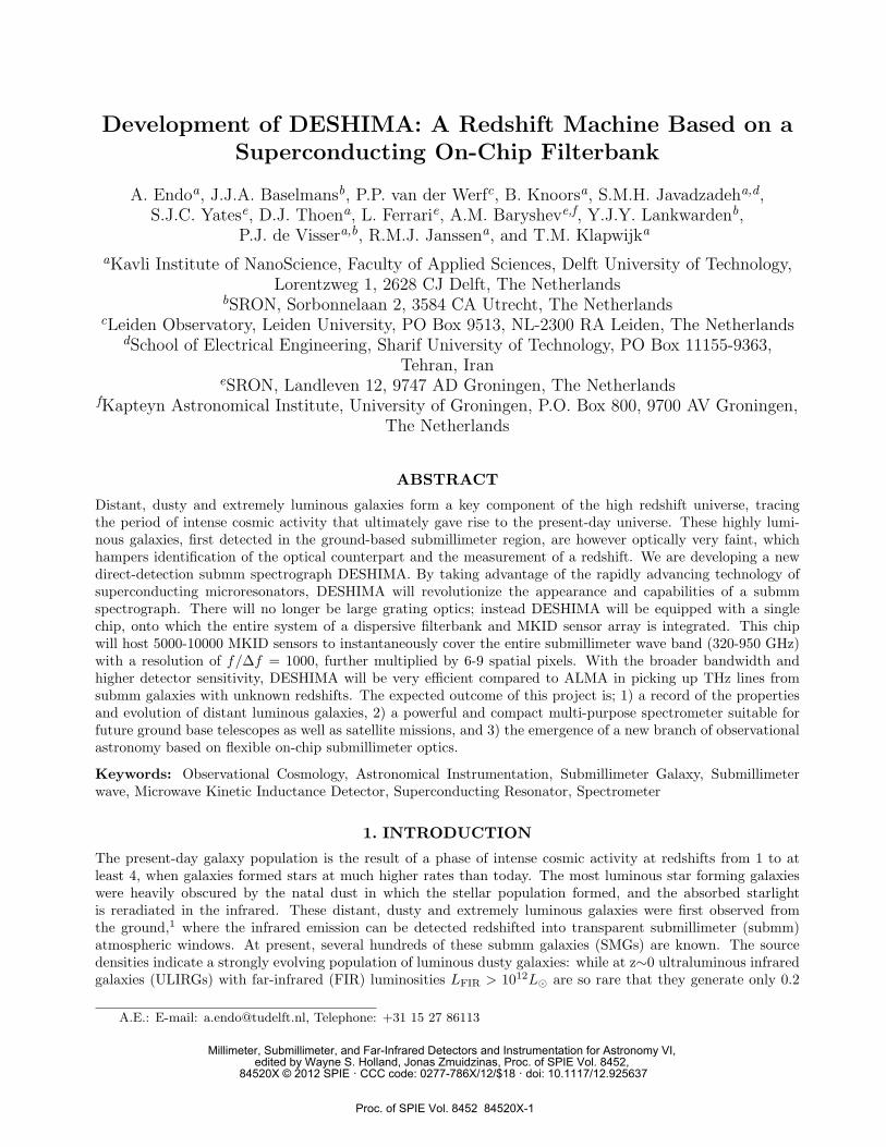
Development of DESHIMA: A Redshift Machine Based on aSuperconducting On-Chip Filterbank
A. Endoa, J.J.A. Baselmansb, P.P. van der Werfc, B. Knoorsa, S.M.H. Javadzadeha,d,S.J.C. Yatese, D.J. Thoena, L. Ferrarie, A.M. Barysheve,f, Y.J.Y. Lankwardenb,
P.J. de Vissera,b, R.M.J. Janssena, and T.M. Klapwijka
aKavli Institute of NanoScience, Faculty of Applied Sciences, Delft University of Technology,Lorentzweg 1, 2628 CJ Delft, The Netherlands
bSRON, Sorbonnelaan 2, 3584 CA Utrecht, The NetherlandscLeiden Observatory, Leiden University, PO Box 9513, NL-2300 RA Leiden, The Netherlands
dSchool of Electrical Engineering, Sharif University of Technology, PO Box 11155-9363,Tehran, Iran
eSRON, Landleven 12, 9747 AD Groningen, The NetherlandsfKapteyn Astronomical Institute, University of Groningen, P.O. Box 800, 9700 AV Groningen,
The Netherlands
ABSTRACT
Distant, dusty and extremely luminous galaxies form a key component of the high redshift universe, tracingthe period of intense cosmic activity that ultimately gave rise to the present-day universe. These highly lumi-nous galaxies, first detected in the ground-based submillimeter region, are however optically very faint, whichhampers identification of the optical counterpart and the measurement of a redshift. We are developing a newdirect-detection submm spectrograph DESHIMA. By taking advantage of the rapidly advancing technology ofsuperconducting microresonators, DESHIMA will revolutionize the appearance and capabilities of a submmspectrograph. There will no longer be large grating optics; instead DESHIMA will be equipped with a singlechip, onto which the entire system of a dispersive filterbank and MKID sensor array is integrated. This chipwill host 5000-10000 MKID sensors to instantaneously cover the entire submillimeter wave band (320-950 GHz)with a resolution of f/∆f = 1000, further multiplied by 6-9 spatial pixels. With the broader bandwidth andhigher detector sensitivity, DESHIMA will be very efficient compared to ALMA in picking up THz lines fromsubmm galaxies with unknown redshifts. The expected outcome of this project is; 1) a record of the propertiesand evolution of distant luminous galaxies, 2) a powerful and compact multi-purpose spectrometer suitable forfuture ground base telescopes as well as satellite missions, and 3) the emergence of a new branch of observationalastronomy based on flexible on-chip submillimeter optics.
Keywords: Observational Cosmology, Astronomical Instrumentation, Submillimeter Galaxy, Submillimeterwave, Microwave Kinetic Inductance Detector, Superconducting Resonator, Spectrometer
1. INTRODUCTION
The present-day galaxy population is the result of a phase of intense cosmic activity at redshifts from 1 to atleast 4, when galaxies formed stars at much higher rates than today. The most luminous star forming galaxieswere heavily obscured by the natal dust in which the stellar population formed, and the absorbed starlightis reradiated in the infrared. These distant, dusty and extremely luminous galaxies were first observed fromthe ground,1 where the infrared emission can be detected redshifted into transparent submillimeter (submm)atmospheric windows. At present, several hundreds of these submm galaxies (SMGs) are known. The sourcedensities indicate a strongly evolving population of luminous dusty galaxies: while at z∼0 ultraluminous infraredgalaxies (ULIRGs) with far-infrared (FIR) luminosities LFIR > 1012L are so rare that they generate only 0.2
A.E.: E-mail: [email protected], Telephone: +31 15 27 86113
Millimeter, Submillimeter, and Far-Infrared Detectors and Instrumentation for Astronomy VI, edited by Wayne S. Holland, Jonas Zmuidzinas, Proc. of SPIE Vol. 8452,
84520X © 2012 SPIE · CCC code: 0277-786X/12/$18 · doi: 10.1117/12.925637
Proc. of SPIE Vol. 8452 84520X-1
% of the local infrared radiation, at z>2 they are responsible for >30 % of the integrated infrared light. Theseobjects form the most luminous portion of an important population of distant dusty galaxies, and an importantmode of galaxy evolution.
A major stumbling block was (and still is) however the faintness of these galaxies at visual wavelengths,which hampers identification of the optical counterpart and the measurement of a redshift. The best availableredshift determination for a significant sample has been achieved by targeting radio-selected SMGs using opticalspectroscopy,2 finding a median z=2.4 and a quartile range z=1.9-2.8. This measurement is however biasedagainst distant galaxies, due to the radio pre-selection. Redshift determinations are fundamental for progress,not only for determining intrinsic luminosities, but also for targeted follow-up in particular spectral lines, and(in the case of larger samples) for studying the evolution of the population properties. The lack of a simple andefficient redshift determination method is becoming acute now that the Herschel mission produces samples ofthousands of distant dusty galaxies, and will be even more sorely felt with the next generation of ground-basedsubmm cameras such as SCUBA-2, which in the coming years will detect thousands of even more distant SMGs.Of course redshift determination for these objects will be possible with the Atacama Large Millimeter Array(ALMA), but even with the full ALMA it will typically take more than an hour to pin down a redshift (seeSec. 6), due to the small instantaneous frequency coverage of heterodyne instrumentation. Therefore even withALMA redshift determination of a significant sample will require a very large amount of observing time.
The need for a rapid and efficient instrument for measuring redshifts in the submm regime has given rise toa new type of submm spectrographs, covering a very wide frequency range using direct detection techniques.These so-called “Z-machines3” capitalize on the fact the SMGs exhibit a number of extremely luminous spectrallines, most notably the [CII] 158 µm line, which can be detected even with existing single dish telescopes. The[CII] line is the principal cooling line of warm (star forming) molecular gas, and its luminosity is typically 0.3 %of the total far-infrared luminosity of dusty galaxies.4 The various submm atmospheric windows give access tothis line at redshifts from 1 to >5, matching perfectly the redshift regime where cosmic star formation activityis at its peak. Using [CII] to trace the evolution of luminous galaxies over cosmic time is a major goal of modernsubmm cosmology and a strong driver for new facilities. Spectral surveys have the further big advantage thatthey map the 3D distribution of galaxies. They therefore provide much more sensitive measurements of clusteringthan continuum imaging (where only the projection of the space distribution is observed, e.g.,5). Such clusteringmeasurements reveal the dark matter halo masses in which SMGs reside and thus provide unique informationon the role of SMGs in the development of large-scale structure and their relation to other families of galaxies.
The first instrument to carry out a successful search for redshifted [CII] emission was ZEUS,6 employinga 32-pixel bolometer array and an echelle grating in the 350 and 450 µm windows. A different instrument,Z-Spec,7 covers the 1 mm window. Next generation submm grating spectrographs (e.g., ZEUS-28) are now beingdeveloped, and such instruments are expected to be cornerstone facilities at future submm observatories suchas the planned 25 m CCAT. These instruments can only compete with ALMA because of their much largerinstantaneous frequency coverage combined with enormous recent advances in sensitive submm sensors. Aneven larger advantage is gained by employing spatial multiplexing, i.e., simultaneous spectroscopy over multiplespatial pixels. With current spectrograph designs, spatial multiplexing is constrained by the limitations imposedby the use of a grating as dispersing element.
This article describes the achievements made so far in the on-going development of a new Z-machine namedDESHIMA (Delft SRON High-Z Mapper). The instrument is founded upon a newly proposed concept of an‘on-chip filterbank,’ which uses a series of superconducting microresonators, instead of an optical grating, todivide the incoming signal into separate wavelength bins. Because not only the physical concept but also thefabrication technology is very similar to microwave kinetic inductance detectors (MKIDs), the filterbank and theMKIDs are naturally integrated onto a single chip.9 This combination has several standout potentials: 1) anorder of magnitude increase in the number of detectors compared to the current generation of Z-machines, fromseveral hundreds to several thousands, 2) extremely large instantaneous bandwidth and the freedom to sampleonly discrete bands within the spectrum, 3) large and flexible spatial multiplexing, and 4) dramatic reduction ininstrument volume and complexity. DESHIMA is designed to cover atmospheric windows in the frequency rangefrom 320 to 950 GHz in one shot, at a spectral resolution (f/∆f) of 1000, and employ 6-9 spatial pixels. Belowwe first describe the DESHIMA concept and design, and then come back to its expected scientific performance.
Proc. of SPIE Vol. 8452 84520X-2
2. ON-CHIP FILTERBANK: PHYSICAL PRINCIPLE AND DESIGN
2.1 Direct detection spectroscopy with MKIDs
The rapid improvement in sensitivity and multiplexability of submm wave direct detectors is making directdetection an attractive option in scenes where used to be the territory of coherent detection. Unlike coherentdetectors, of which the sensitivity is ultimately limited by the quantum noise coming from the energy-timeuncertainty principle of photons, direct detectors can reach the photon noise limit, as long as the detector noiseequivalent power (NEPdet =
√Sdet/(dX/dP ), where Sdet is the detector noise and dX/dP is the responsivity)
is smaller than the photon noise. The photon noise equivalent power, NEPph, scales with the optical loadingpower on the detector P as
NEPph =√
2PhF (1 + mB), (1)
where F is the signal frequency, B is the photon occupation number per mode and m the efficiency from emissionto detection of one mode. Additionally, pair breaking detectors suffer from random recombination noise, butthat this effect is very small as discussed by Yates et al.10 A frequency-selecting element in front of the detectorwith a resolution of R = f/∆f would decrease the optical power by 1/R, so the detector noise must go down inproportion to 1/R in order to stay in the photon-noise limit: NEPph NEPdet. In addition, in order to achievethe same bandwidth, the number of detectors, or channels, must increase also in proportion to R. Naturally, thenumber of detectors required also scales with the number of spatial pixels.
The high sensitivity , and particularly the high multiplexability of MKIDs make them an interesting candidatefor the detecting elements in a broadband, multi-pixel direct-detection spectrometer. Lens-antenna coupledNbTiN/Al hybrid MKIDs have demonstrated10 photon-noise limited sensitivity under optical loading powersdown to 0.1 pW. This corresponds roughly to the optical power that will be received by a detector behind anR = 1000 spectrograph operating at 350 GHz on a good night at the APEX telescope. By using 10,000 of suchMKIDs, which is planned for next generation direct detection cameras, one would have enough detectors to coverthe entire submillimeter window with ∼10 spatial pixels.
2.2 On-chip filterbank using superconducting resonators
Optical gratings are fundamentally limited in their scalability. To achieve a resolution of R, the light must travelfor a distance of ∼λR, so that signals with wavelength λ and λ+λ/R have a significant difference in their phaseafter their travel.11 Taking λ=1 mm and R = 1000, this distance would be 1 m, which starts to exceed the sizeof a typical cryogenic instrument.
In such a situation, it is common in the field of optics to construct a mirror cavity to fold the optical pathby a number equal to the quality factor Q of the cavity. In the microwave regime, this can be achieved by usinga filterbank, consisting of e.g., coaxial cable resonators.12 Since we are interested in the submm domain, we canmake the resonators out of planar superconducting transmission lines to integrate the entire filterbank onto achip.9,13
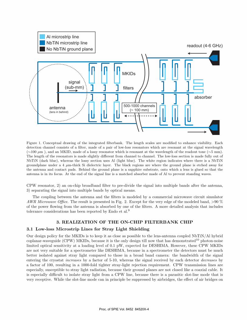
In Fig. 1 is shown a conceptual drawing of the integrated filterbank that is envisioned for DESHIMA. Thesignal is received by a broadband antenna (see Sec. 3.3), and transmitted along a microstrip line (MSL) made ofNbTiN. NbTiN has a gap frequency of about 1.1 THz, so the signal will travel without breaking Cooper pairs.From this ‘signal line’ branch 500-1000 MSL half wavelength resonators, also made of NbTiN. These resonantfilters are capacitively coupled on one side to the signal line, and on the other side to an MKID. Each resonantfilter has a different length, and filters for shorter wavelengths are placed closer to the antenna because thesubmm loss per length increases with frequency. The MKID is a NbTiN/Al-hybrid MSL microwave resonator,in a similar way as the coplanar waveguide (CPW) MKIDs reported by Yates et al.10 The total length of thefilterbank is likely to be determined by the length of the coupling section between the MKID and the signalreadout line, limiting the minimum inter-channel distance to ∼ 300µm , resulting in a total length of ∼100 mmfor ∼700 channels.
It is worth noting that the half-wave filters, considered for the prototype, prohibit the bandwidth to exceed1 octave. There are several ways of extending the bandwidth to cover the entire DESHIMA bandwidth of 1.5octave, for example: 1) using a quarter wave filter resonator made of a MSL with a via-hole, or a grounded
Proc. of SPIE Vol. 8452 84520X-3
500-1000 channels (~ 100 mm)
MKIDs
filters
antenna(lens in behind)
signal(sub-mm)
readout (4-6 GHz)No NbTiN ground plane
NbTiN microstrip line
Al microstrip line
absorber
Figure 1. Conceptual drawing of the integrated filterbank. The length scales are modified to enhance visibility. Eachdetection channel consists of a filter, made of a pair of low-loss resonators which are resonant at the signal wavelength(∼100 µm ), and an MKID, made of a lossy resonator which is resonant at the wavelength of the readout tone (∼5 mm).The length of the resonators is made slightly different from channel to channel. The low-loss section is made fully out ofNbTiN (dark blue), whereas the lossy section uses Al (light blue). The white region indicates where there is a NbTiNgroundplane under a 4 µm-thick Si dielectric layer. The black regions are where the ground plane is etched away forthe antenna and contact pads. Behind the ground plane is a sapphire substrate, onto which a lens is glued so that theantenna is in its focus. At the end of the signal line is a matched absorber made of Al to prevent standing waves.
CPW resonator, 2) an on-chip broadband filter to pre-divide the signal into multiple bands after the antenna,3) separating the signal into multiple bands by optical means.
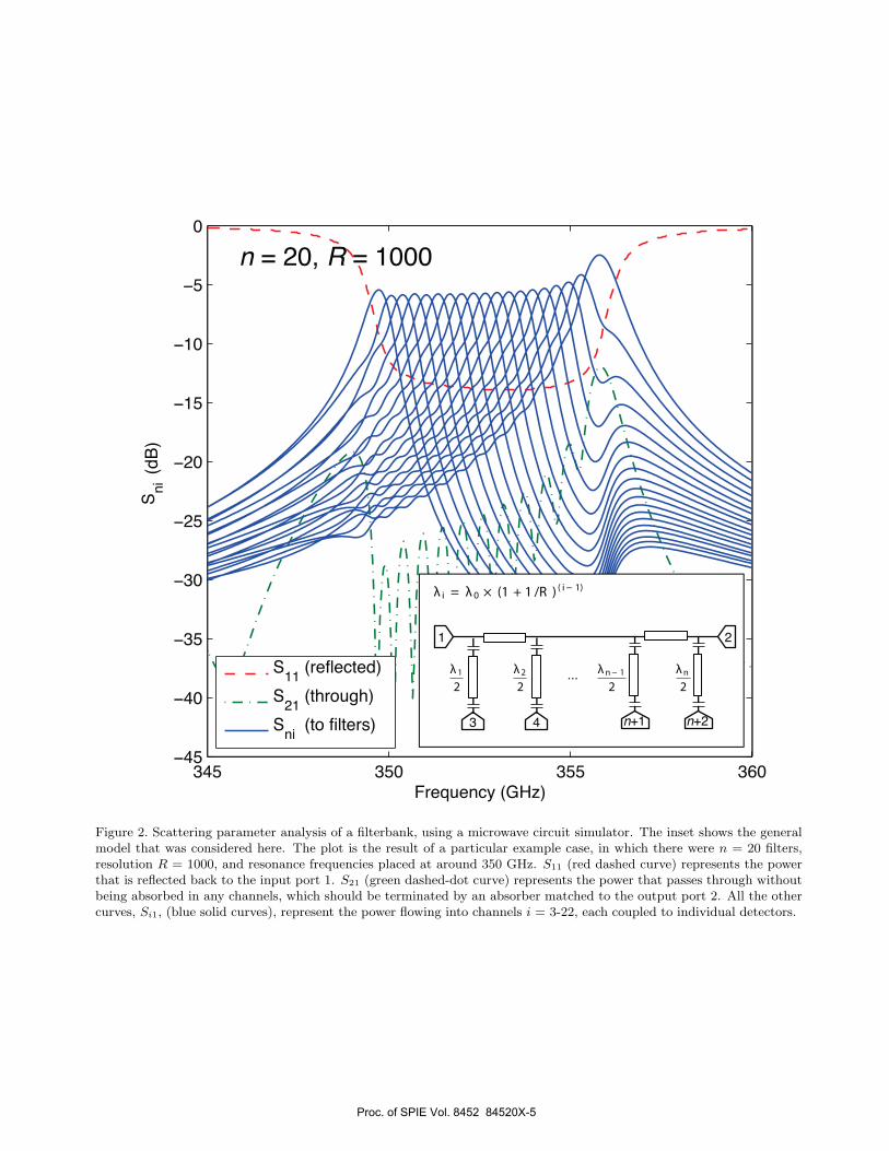
The coupling between the antenna and the filters is modeled by a commercial microwave circuit simulatorAWR Microwave Office. The result is presented in Fig. 2. Except for the very edge of the modeled band, >90 %of the power flowing from the antenna is absorbed by one of the filters. A more detailed analysis that includestolerance considerations has been reported by Endo et al.9
3. REALIZATION OF THE ON-CHIP FILTERBANK CHIP
3.1 Low-loss Microstrip Lines for Stray Light Shielding
Our design policy for the MKIDs is to keep it as close as possible to the lens-antenna coupled NbTiN/Al hybridcoplanar-waveguide (CPW) MKIDs, because it is the only design till now that has demonstrated10 photon-noiselimited optical sensitivity at a loading level of 0.1 pW, expected for DESHIMA. However, these CPW MKIDsare not very suitable for a spectrometer like DESHIMA, because in a spectrometer the detectors must be muchbetter isolated against stray light compared to those in a broad band camera: the bandwidth of the signalentering the cryostat increases by a factor of 5-10, whereas the signal received by each detector decreases bya factor of 100, resulting in a 1000-fold tighter stray-light rejection requirement. CPW transmission lines areespecially, susceptible to stray light radiation, because their ground planes are not closed like a coaxial cable. Itis especially difficult to isolate stray light from a CPW line, because there is a parasitic slot-line mode that isvery receptive. While the slot-line mode can in principle be suppressed by airbridges, the effect of air bridges on
Proc. of SPIE Vol. 8452 84520X-4
345 350 355 360−45
−40
−35
−30
−25
−20
−15
−10
−5
0
Frequency (GHz)
Sni
S11 (reflected)
S21 (through)
Sni (to filters)
λ 1
2
λ 2
2
λn− 1
2
λn
2
λ i = λ 0 × (1 + 1 /R )( i− 1)
Figure 2. Scattering parameter analysis of a filterbank, using a microwave circuit simulator. The inset shows the generalmodel that was considered here. The plot is the result of a particular example case, in which there were n = 20 filters,resolution R = 1000, and resonance frequencies placed at around 350 GHz. S11 (red dashed curve) represents the powerthat is reflected back to the input port 1. S21 (green dashed-dot curve) represents the power that passes through withoutbeing absorbed in any channels, which should be terminated by an absorber matched to the output port 2. All the othercurves, Si1, (blue solid curves), represent the power flowing into channels i = 3-22, each coupled to individual detectors.
Proc. of SPIE Vol. 8452 84520X-5
a submillimeter wave transmission line has not been well studied, and could become problematic when it comesto accurately controlling the path length of the filters.
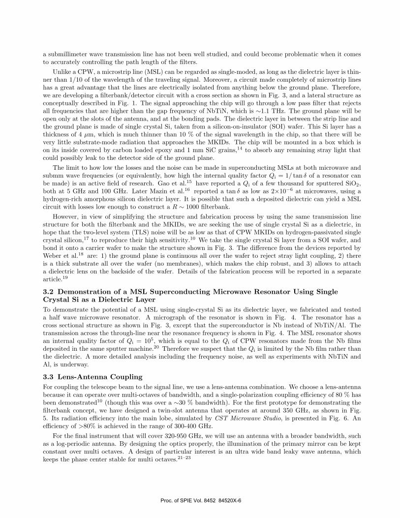
Unlike a CPW, a microstrip line (MSL) can be regarded as single-moded, as long as the dielectric layer is thin-ner than 1/10 of the wavelength of the traveling signal. Moreover, a circuit made completely of microstrip lineshas a great advantage that the lines are electrically isolated from anything below the ground plane. Therefore,we are developing a filterbank/detector circuit with a cross section as shown in Fig. 3, and a lateral structure asconceptually described in Fig. 1. The signal approaching the chip will go through a low pass filter that rejectsall frequencies that are higher than the gap frequency of NbTiN, which is ∼1.1 THz. The ground plane will beopen only at the slots of the antenna, and at the bonding pads. The dielectric layer in between the strip line andthe ground plane is made of single crystal Si, taken from a silicon-on-insulator (SOI) wafer. This Si layer has athickness of 4 µm, which is much thinner than 10 % of the signal wavelength in the chip, so that there will bevery little substrate-mode radiation that approaches the MKIDs. The chip will be mounted in a box which ison its inside covered by carbon loaded epoxy and 1 mm SiC grains,14 to absorb any remaining stray light thatcould possibly leak to the detector side of the ground plane.
The limit to how low the losses and the noise can be made in superconducting MSLs at both microwave andsubmm wave frequencies (or equivalently, how high the internal quality factor Qi = 1/ tan δ of a resonator canbe made) is an active field of research. Gao et al.15 have reported a Qi of a few thousand for sputtered SiO2,both at 5 GHz and 100 GHz. Later Mazin et al.16 reported a tan δ as low as 2×10⁻⁶ at microwaves, using ahydrogen-rich amorphous silicon dielectric layer. It is possible that such a deposited dielectric can yield a MSLcircuit with losses low enough to construct a R ∼ 1000 filterbank.
However, in view of simplifying the structure and fabrication process by using the same transmission linestructure for both the filterbank and the MKIDs, we are seeking the use of single crystal Si as a dielectric, inhope that the two-level system (TLS) noise will be as low as that of CPW MKIDs on hydrogen-passivated singlecrystal silicon,17 to reproduce their high sensitivity.10 We take the single crystal Si layer from a SOI wafer, andbond it onto a carrier wafer to make the structure shown in Fig. 3. The difference from the devices reported byWeber et al.18 are: 1) the ground plane is continuous all over the wafer to reject stray light coupling, 2) thereis a thick substrate all over the wafer (no membranes), which makes the chip robust, and 3) allows to attacha dielectric lens on the backside of the wafer. Details of the fabrication process will be reported in a separatearticle.19
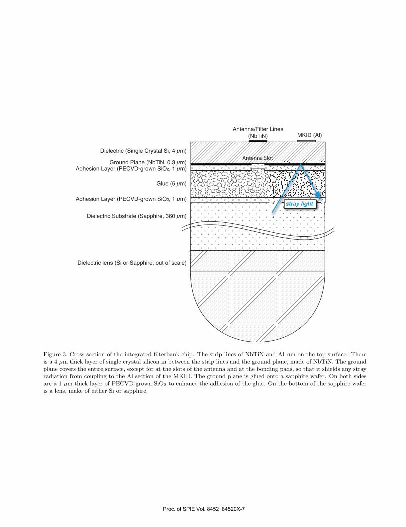
3.2 Demonstration of a MSL Superconducting Microwave Resonator Using SingleCrystal Si as a Dielectric LayerTo demonstrate the potential of a MSL using single-crystal Si as its dielectric layer, we fabricated and testeda half wave microwave resonator. A micrograph of the resonator is shown in Fig. 4. The resonator has across sectional structure as shown in Fig. 3, except that the superconductor is Nb instead of NbTiN/Al. Thetransmission across the through-line near the resonance frequency is shown in Fig. 4. The MSL resonator showsan internal quality factor of Qi = 105, which is equal to the Qi of CPW resonators made from the Nb filmsdeposited in the same sputter machine.20 Therefore we suspect that the Qi is limited by the Nb film rather thanthe dielectric. A more detailed analysis including the frequency noise, as well as experiments with NbTiN andAl, is underway.
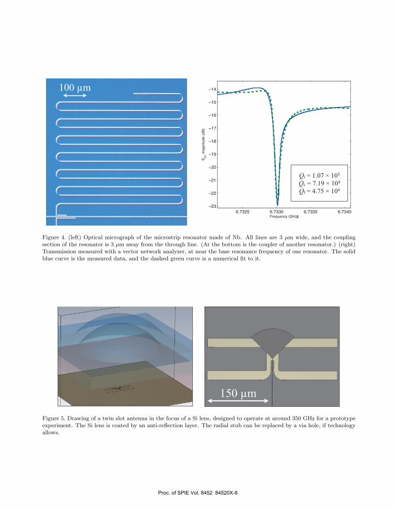
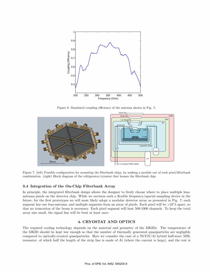
3.3 Lens-Antenna CouplingFor coupling the telescope beam to the signal line, we use a lens-antenna combination. We choose a lens-antennabecause it can operate over multi-octaves of bandwidth, and a single-polarization coupling efficiency of 80 % hasbeen demonstrated10 (though this was over a ∼30 % bandwidth). For the first prototype for demonstrating thefilterbank concept, we have designed a twin-slot antenna that operates at around 350 GHz, as shown in Fig.5. Its radiation efficiency into the main lobe, simulated by CST Microwave Studio, is presented in Fig. 6. Anefficiency of >80% is achieved in the range of 300-400 GHz.
For the final instrument that will cover 320-950 GHz, we will use an antenna with a broader bandwidth, suchas a log-periodic antenna. By designing the optics properly, the illumination of the primary mirror can be keptconstant over multi octaves. A design of particular interest is an ultra wide band leaky wave antenna, whichkeeps the phase center stable for multi octaves.21–23
Proc. of SPIE Vol. 8452 84520X-6
YJ 5-SL
Antenna/Filter Lines
(NbTiN) MKID (Al)
Antenna Slot
Dielectric (Single Crystal Si, 4 µm)
Ground Plane (NbTiN, 0.3 µm)Adhesion Layer (PECVD-grown SiO2, 1 µm)
Adhesion Layer (PECVD-grown SiO2, 1 µm)
Dielectric Substrate (Sapphire, 360 µm)
Dielectric lens (Si or Sapphire, out of scale)
Glue (5 µm)
stray lightstray light
Figure 3. Cross section of the integrated filterbank chip. The strip lines of NbTiN and Al run on the top surface. Thereis a 4 µm thick layer of single crystal silicon in between the strip lines and the ground plane, made of NbTiN. The groundplane covers the entire surface, except for at the slots of the antenna and at the bonding pads, so that it shields any strayradiation from coupling to the Al section of the MKID. The ground plane is glued onto a sapphire wafer. On both sidesare a 1 µm thick layer of PECVD-grown SiO2 to enhance the adhesion of the glue. On the bottom of the sapphire waferis a lens, make of either Si or sapphire.
Proc. of SPIE Vol. 8452 84520X-7
- ,!
100 µm
!"#$%& !"#$$' !(#$$& !"#$)'
%$
%%
%*
%'
*+
*,
*#
*!
*&
*)
-./01/23456789:
;%*5<=>2?@1A/56AB:
Qi = 1.07 × 10⁵
Qc = 7.19 × 10⁴
Ql = 4.75 × 10⁴
Figure 4. (left) Optical micrograph of the microstrip resonator made of Nb. All lines are 3 µm wide, and the couplingsection of the resonator is 3 µm away from the through line. (At the bottom is the coupler of another resonator.) (right)Transmission measured with a vector network analyzer, at near the base resonance frequency of one resonator. The solidblue curve is the measured data, and the dashed green curve is a numerical fit to it.
150 µm
Figure 5. Drawing of a twin slot antenna in the focus of a Si lens, designed to operate at around 350 GHz for a prototypeexperiment. The Si lens is coated by an anti-reflection layer. The radial stub can be replaced by a via hole, if technologyallows.
Proc. of SPIE Vol. 8452 84520X-8
200 250 300 350 400 450 500
0.4
0.5
0.6
0.7
0.8
0.9
1
Frequency (GHz)
Cou
plin
g E
ffici
ency
Figure 6. Simulated coupling efficiency of the antenna shown in Fig. 5.
50mm
ADR
PT
300K
70K
4K
0.8K
0.14K
Gore-Tex
Gore-Tex
1.5 THz LPF
1THz LPF
2 x 6 readout SMA cables
magnetic shield
Figure 7. (left) Possible configuration for mounting the filterbank chips, by making a module out of each pixel/filterbankcombiniation. (right) Block diagram of the refrigerator/cryostat that houses the filterbank chip.
3.4 Integration of the On-Chip Filterbank Array
In principle, the integrated filterbank design allows the designer to freely choose where to place multiple lens-antenna pixels on the detector chip. While we envision such a flexible frequency/spacial sampling device in thefuture, for the first prototypes we will most likely adopt a modular detector array as presented in Fig. 7; eachsegment has one lens-antenna, and multiple segments form an array of pixels. Each pixel will be >2Fλ apart, sothat no truncation of the beam is necessary. Each pixel segment will host 500-1000 channels. To keep the totalarray size small, the signal line will be bent at least once.
4. CRYOSTAT AND OPTICS
The required cooling technology depends on the material and geometry of the MKIDs. The temperature ofthe MKID should be kept low enough so that the number of thermally generated quasiparticles are negligiblecompared to optically-created quasiparticles. Here we consider the case of a NbTiN/Al hybrid half-wave MSLresonator, of which half the length of the strip line is made of Al (where the current is large), and the rest is
Proc. of SPIE Vol. 8452 84520X-9
20
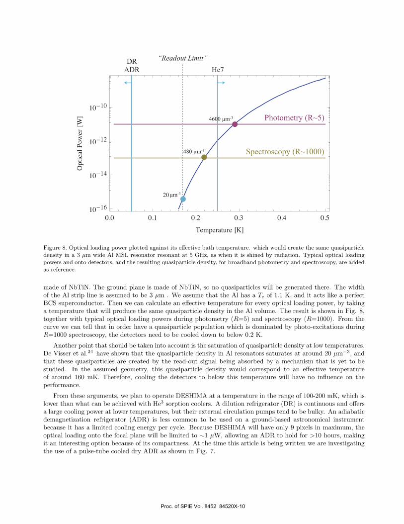
Figure 8. Optical loading power plotted against its effective bath temperature. which would create the same quasiparticledensity in a 3 µm wide Al MSL resonator resonant at 5 GHz, as when it is shined by radiation. Typical optical loadingpowers and onto detectors, and the resulting quasiparticle density, for broadband photometry and spectroscopy, are addedas reference.
made of NbTiN. The ground plane is made of NbTiN, so no quasiparticles will be generated there. The widthof the Al strip line is assumed to be 3 µm . We assume that the Al has a Tc of 1.1 K, and it acts like a perfectBCS superconductor. Then we can calculate an effective temperature for every optical loading power, by takinga temperature that will produce the same quasiparticle density in the Al volume. The result is shown in Fig. 8,together with typical optical loading powers during photometry (R=5) and spectroscopy (R=1000). From thecurve we can tell that in order have a quasiparticle population which is dominated by photo-excitations duringR=1000 spectroscopy, the detectors need to be cooled down to below 0.2 K.
Another point that should be taken into account is the saturation of quasiparticle density at low temperatures.De Visser et al.24 have shown that the quasiparticle density in Al resonators saturates at around 20 µm−3, andthat these quasiparticles are created by the read-out signal being absorbed by a mechanism that is yet to bestudied. In the assumed geometry, this quasiparticle density would correspond to an effective temperatureof around 160 mK. Therefore, cooling the detectors to below this temperature will have no influence on theperformance.
From these arguments, we plan to operate DESHIMA at a temperature in the range of 100-200 mK, which islower than what can be achieved with He3 sorption coolers. A dilution refrigerator (DR) is continuous and offersa large cooling power at lower temperatures, but their external circulation pumps tend to be bulky. An adiabaticdemagnetization refrigerator (ADR) is less common to be used on a ground-based astronomical instrumentbecause it has a limited cooling energy per cycle. Because DESHIMA will have only 9 pixels in maximum, theoptical loading onto the focal plane will be limited to ∼1 µW, allowing an ADR to hold for >10 hours, makingit an interesting option because of its compactness. At the time this article is being written we are investigatingthe use of a pulse-tube cooled dry ADR as shown in Fig. 7.
Proc. of SPIE Vol. 8452 84520X-10
Euvis AWG472 DAC
RF board
to ground station
4DSP FC6301
Virtex 6 carrier card4DSP FMC126 ADC
NLR
OPDP board
carrier comb
I + Q
up conversion
down conversion
I + Q
WOLA
FFT and bin select
KID array
synchronized
clocks
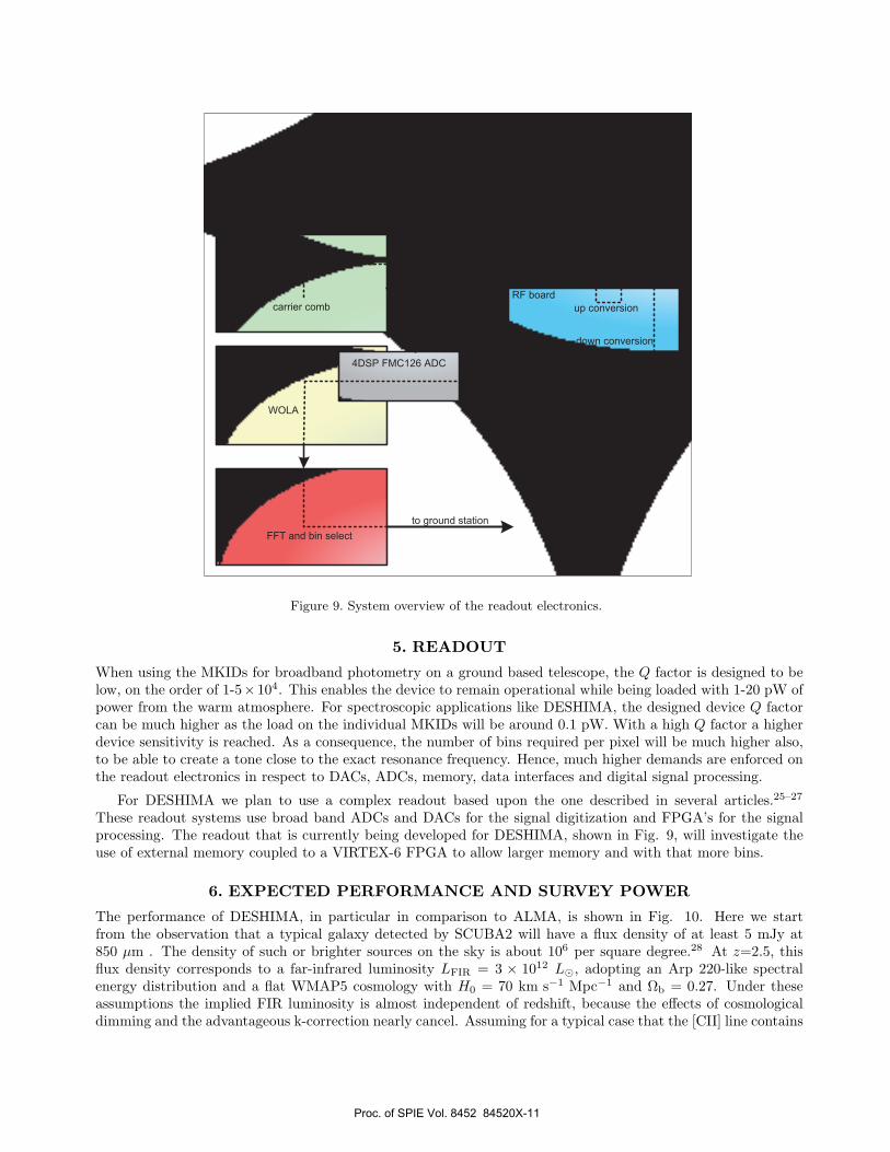
Figure 9. System overview of the readout electronics.
5. READOUT
When using the MKIDs for broadband photometry on a ground based telescope, the Q factor is designed to below, on the order of 1-5×10⁴. This enables the device to remain operational while being loaded with 1-20 pW ofpower from the warm atmosphere. For spectroscopic applications like DESHIMA, the designed device Q factorcan be much higher as the load on the individual MKIDs will be around 0.1 pW. With a high Q factor a higherdevice sensitivity is reached. As a consequence, the number of bins required per pixel will be much higher also,to be able to create a tone close to the exact resonance frequency. Hence, much higher demands are enforced onthe readout electronics in respect to DACs, ADCs, memory, data interfaces and digital signal processing.
For DESHIMA we plan to use a complex readout based upon the one described in several articles.25–27
These readout systems use broad band ADCs and DACs for the signal digitization and FPGA’s for the signalprocessing. The readout that is currently being developed for DESHIMA, shown in Fig. 9, will investigate theuse of external memory coupled to a VIRTEX-6 FPGA to allow larger memory and with that more bins.
6. EXPECTED PERFORMANCE AND SURVEY POWER
The performance of DESHIMA, in particular in comparison to ALMA, is shown in Fig. 10. Here we startfrom the observation that a typical galaxy detected by SCUBA2 will have a flux density of at least 5 mJy at850 µm . The density of such or brighter sources on the sky is about 106 per square degree.28 At z=2.5, thisflux density corresponds to a far-infrared luminosity LFIR = 3 × 10¹² L, adopting an Arp 220-like spectralenergy distribution and a flat WMAP5 cosmology with H0 = 70 km s−1 Mpc−1 and Ωb = 0.27. Under theseassumptions the implied FIR luminosity is almost independent of redshift, because the effects of cosmologicaldimming and the advantageous k-correction nearly cancel. Assuming for a typical case that the [CII] line contains
Proc. of SPIE Vol. 8452 84520X-11
0.3 % of the total FIR luminosity (as discussed in Sect. 1), the line flux is given by the red curve in Fig. 10.While ALMA will produce a 5σ detection of such a line in only 2-4 minutes (depending on observing frequency),it will need to combine 23 separate tunings to cover the indicated redshift interval, leading to a time requirementof about 1.5 hours even with the full ALMA (and this excludes overheads for tuning, calibration etc). Dueto its much larger frequency coverage, in the same 1.5 hours (also excluding overheads) DESHIMA will reachgreater depth and cover a much larger redshift interval. These calculations assume a precipitable water vapor(PWV) column of 0.4 mm, corresponding to the best octile of conditions at the APEX site. The calculationassumes realistic DESHIMA design goals (i.e., transmission of 50 % at the cryostat entrance window, 40 % atthe single-polarized lens and 60 % for the filterbank). Fig. 6 also shows a fairly uniform sensitivity to [CII]emission as a function of redshift, with the exception of the opaque gaps between atmospheric windows, enablinga fairly uniform survey over the redshift interval indicated even without considering completeness corrections.Other lines (e.g., [OI], [OIII], [NII] or bright CO lines) from distant galaxies will be about an order of magnitudesfainter than the [CII] lines, so that there is no danger of misidentifying a bright line. However, gravitationallylensed galaxies will be detectable in a number of fainter lines as well, and DESHIMA will be ideal for findingthe redshift and characterizing excitation conditions in such galaxies in one shot. This is a powerful applicationnow that Herschel is finding distant gravitationally lensed dusty galaxies in large numbers.
Finally, we note that since the submm source counts are extremely steep, there is a significant probability ofserendipitous blank field detections in a typical 1.5 hour integration with DESHIMA. At the DESHIMA detectionlimit implied by Fig. 10, the source density rises to about 5 × 10⁶ per square degree, and the vast majority ofthese sources will be between redshifts 1 and 5.28 Using 1.5 hour integrations, a 9-pixel DESHIMA will have ablank field detection rate of approximately one in every three pointings. This calculation shows that with even amodest expansion, DESHIMA will be able to do efficient blank field surveys. It also underlines the extraordinarypower of DESHIMA or a successor with more spatial multiplexing on future facilities such as CCAT.
7. CONCLUSION
We have described the achievements up to now in the design and technological development of DESHIMA, anon-chip submm wave broad band spectrometer. DESHIMA targets at detecting the [CII] line from galaxies inthe redshift range of 1-5, with up to 9 pixels. The demonstration of MSL microwave resonators with low loss isa milestone towards realizing an on-chip filterbank chip with a high degree of stray light shielding. We expectto bring the first prototype instrument with a limited bandwidth and pixel number to the APEX telescope, orpossibly to the ASTE telescope, in 1-2 years.
ACKNOWLEDGMENTS
This work is partially financed by the Netherlands Organization for Scientific Research (NWO; contract number614.061.611). AE is financially supported by NWO (Veni grant 639.041.023) and JSPS Fellowship for ResearchAbroad. TMK likes to acknowledge support by NOVA for RMJJ.
REFERENCES[1] Smail, I., Ivison, R. J., and Blain, A. W., “A Deep Submillimeter Survey of Lensing Clusters: A New
Window on Galaxy Formation and Evolution,” ApJ 490, L5 (1997).[2] Chapman, S. C., Blain, A. W., Ivison, R. J., and Smail, I., “A Median Redshift of 2.4 for Galaxies Bright
at Submillimetre Wavelengths,” Nature 422, 695 (2003).[3] Baker, A. J., Glenn, J., Harris, A. I., Mangum, J. G., and Yun, M. S., “From Z-Machines to ALMA:
(Sub)Millimeter Spectroscopy of Galaxies,” (2007).[4] Gracia-Carpio, J., Sturm, E., Hailey-Dunsheath, S., Fischer, J., Contursi, A., Poglitsch, A., Genzel, R.,
Gonzalez-Alfonso, E., Sternberg, A., Verma, A., Christopher, N., Davies, R., Feuchtgruber, H., de Jong,J. A., Lutz, D., and Tacconi, L. J., “Far-Infrared Line Deficits in Galaxies with Extreme LFIR/MH2 Ratios,”ApJ 728, L7 (2011).
Proc. of SPIE Vol. 8452 84520X-12
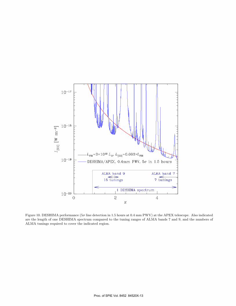
Figure 10. DESHIMA performance (5σ line detection in 1.5 hours at 0.4 mm PWV) at the APEX telescope. Also indicatedare the length of one DESHIMA spectrum compared to the tuning ranges of ALMA bands 7 and 9, and the numbers ofALMA tunings required to cover the indicated region.
Proc. of SPIE Vol. 8452 84520X-13
[5] Amblard, A., Cooray, A., Serra, P., Altieri, B., Arumugam, V., Aussel, H., Blain, A., Bock, J., Boselli, A.,Buat, V., Castro-Rodrıguez, N., Cava, A., Chanial, P., Chapin, E., Clements, D. L., Conley, A., Conversi, L.,Dowell, C. D., Dwek, E., Eales, S., Elbaz, D., Farrah, D., Franceschini, A., Gear, W., Glenn, J., Griffin, M.,Halpern, M., Hatziminaoglou, E., Ibar, E., Isaak, K., Ivison, R. J., Khostovan, A. A., Lagache, G., Levenson,L., Lu, N., Madden, S., Maffei, B., Mainetti, G., Marchetti, L., Marsden, G., Mitchell-Wynne, K., Nguyen,H. T., O’halloran, B., Oliver, S. J., Omont, A., Page, M. J., Panuzzo, P., Papageorgiou, A., Pearson, C. P.,Perez-Fournon, I., Pohlen, M., Rangwala, N., Roseboom, I. G., Rowan-Robinson, M., Sanchez Portal, M.,Schulz, B., Scott, D., Seymour, N., Shupe, D. L., Smith, A. J., Stevens, J. A., Symeonidis, M., Trichas,M., Tugwell, K., Vaccari, M., Valiante, E., Valtchanov, I., Vieira, J. D., Vigroux, L., Wang, L., Ward, R.,Wright, G., K Xu, C., and Zemcov, M., “Submillimetre Galaxies Reside in Dark Matter Haloes with MassesGreater Than 3 × 10¹¹ Solar Masses,” Nature 470, 510 (2011).
[6] Stacey, G. J., Hailey-Dunsheath, S., Ferkinhoff, C., Nikola, T., Parshley, S. C., Benford, D. J., Staguhn,J. G., and Fiolet, N., “A 158 Micron [CII] Line Survey of Galaxies at z∼1 to 2: An Indicator of StarFormation in the Early Universe,” ApJ 724, 957 (2010).
[7] Inami, H., Bradford, M., Aguirre, J., Earle, L., Naylor, B., Matsuhara, H., Glenn, J., Nguyen, H., Bock,J. J., Zmuidzinas, J., and Ohyama, Y., “A Broadband Millimeter-Wave Spectrometer Z-spec: Sensitivityand ULIRGs,” SPIE Conference Series 7020 (2008).
[8] Ferkinhoff, C., Nikola, T., Parshley, S. C., Stacey, G. J., Irwin, K. D., Cho, H., and Halpern, M., “ZEUS-2:A Second Generation Submillimeter Grating Spectrometer for Exploring Distant Galaxies,” Proceedings ofSPIE 7741, 77410Y (2010).
[9] Endo, A., van der Werf, P. P., Janssen, R. M. J., de Visser, P. J., Klapwijk, T. M., Baselmans, J. J. A.,Ferrari, L., Baryshev, A. M., and Yates, S. J. C., “Design of an Integrated Filterbank for DESHIMA: On-Chip Submillimeter Imaging Spectrograph Based on Superconducting Resonators,” J. Low Temp. Phys. 167,341 (2012).
[10] Yates, S. J. C., Baselmans, J. J. A., Endo, A., Janssen, R. M. J., Ferrari, L., Diener, P., and Baryshev, A. M.,“Photon Noise Limited Radiation Detection With Lens-Antenna Coupled Microwave Kinetic InductanceDetectors,” Appl. Phys. Lett. 99, 073505 (2011).
[11] Zmuidzinas, J., “The role of coherent detection,” in [New Concepts for Far-Infrared and Submillimeter SpaceAstronomy ], 329 (2004).
[12] Tauber, J. A. and Erickson, N. R., “A Low cost Filterbank Spectrometer for Submm Observations in RadioAstronomy,” Rev. Sci. Instrum. 62, 1288 (1991).
[13] Shirokoff, E. D., Barry, P., Bradford, C. M., Day, P. K., Doyle, S. M., Hailey-Dunsheath, S., Kovacs, A.,McKenny, C., LeDuc, H. G., Llombart, N., Marrone, D. P., Mauskopf, P. D., O’Brient, R. C., Padin, S.,Swenson, L. J., and Zmuidzinas, J., “MKID development for superspec: an on-chip, mm-wave, filterbankspectrometer,” this proceedings (2012).
[14] Baselmans, J. J. A., Yates, S. J. C., Diener, P., and de Visser, P. J., “Ultra Low Background CryogenicTest Facility for Far-Infrared Radiation Detectors,” Journal of Low Temperature Physics 167, 360 (2012).
[15] Gao, J., Vayonakis, A., Noroozian, O., Zmuidzinas, J., Day, P. K., LeDuc, H. G., Young, B., Cabrera, B.,and Miller, A., “Measurement of Loss in Superconducting Microstrip at Millimeterwave Frequencies,” in[Proceedings of LTD13 ], 164 (2009).
[16] Mazin, B. A., Sank, D., Mchugh, S., Lucero, E. A., Merrill, A., Gao, J., Pappas, D., Moore, D., andZmuidzinas, J., “Thin Film Dielectric Microstrip Kinetic Inductance Detectors,” Appl. Phys. Lett. 96,102504 (2010).
[17] Barends, R., Vercruyssen, N., Endo, A., de Visser, P. J., Zijlstra, T., Klapwijk, T. M., and Baselmans, J.J. A., “Reduced Frequency Noise in Superconducting Resonators,” Appl. Phys. Lett. 97, 3507 (2010).
[18] Weber, S. J., Murch, K. W., Slichter, D. H., Vijay, R., and Siddiqi, I., “Single Crystal Silicon CapacitorsWith Low Microwave Loss in the Single Photon Regime,” Appl. Phys. Lett. 98, 172510 (2011).
[19] Knoors et al., in prep.[20] Barends, R., Baselmans, J. J. A., Hovenier, J. N., Gao, J. R., Yates, S. J. C., Klapwijk, T. M., and
Hoevers, H. F. C., “Niobium and Tantalum High Q Resonators for Photon Detectors,” IEEE Trans. Appl.Supercond. 17, 263 (2007).
Proc. of SPIE Vol. 8452 84520X-14
[21] Baryshev, A. M., Baselmans, J. J. A., Freni, A., Gerini, G., Hoevers, H. F. C., Iacono, A., and Neto, A.,“Progress in Antenna Coupled Kinetic Inductance Detectors,” IEEE T. THz Sci. Technol. 1, 112 (2011).
[22] Neto, A., “UWB, Non Dispersive Radiation From the Planarly Fed Leaky Lens Antenna—Part 1: Theoryand Design,” IEEE T. Antenn. Propag. 58, 2238 (2010).
[23] Neto, A., Monni, S., and Nennie, F., “UWB, Non Dispersive Radiation From the Planarly Fed Leaky LensAntenna—Part II: Demonstrators and Measurements,” IEEE T. Antenn. Propag. 58, 2248 (2010).
[24] de Visser, P. J., Baselmans, J. J. A., Yates, S. J. C., Diener, P., Endo, A., and Klapwijk, T. M., “Microwave-induced Excess Quasiparticles in Superconducting Resonators Measured Through Correlated ConductivityFluctuations,” Appl. Phys. Lett. 100, 2601 (2012).
[25] Yates, S. J. C., Baryshev, A. M., Baselmans, J. J. A., Klein, B., and Gusten, R., “Fast fourier transformspectrometer readout for large arrays of microwave kinetic inductance detectors,” AppL. Phys. Lett. 95,042504 (2009).
[26] Bourrion, O., Bideaud, A., Benoit, A., Cruciani, A., Macias-Perez, J. F., Monfardini, A., Roesch, M.,Swenson, L., and Vescovi, C., “Electronics and data acquisition demonstrator for a kinetic inductancecamera,” JINST 6, P06012 (2011).
[27] McHugh, S., Mazin, A., Serfass, B., Meeker, S., O’Brien, K., Duan, R., Raffanti, R., and Werthimer, D., “Areadout for large arrays of microwave kinetic inductance detectors,” Review of Scientific Instruments 83,044702 (2012).
[28] Rahmati, A. and van der Werf, P. P., “Genesis of the Dusty Universe: Modelling Submillimetre SourceCounts,” MNRAS 418, 176 (2011).
Proc. of SPIE Vol. 8452 84520X-15
Copyright © 2022 FDOKUMEN