Chip Preparation - Enviro Knowledge Center
17
The recovery and use of paper for recycling have been on the increase, as the proportion of fiber obtained by recycling has been increasing. Globally, recycled fiber accounts for well over 40% of pulp fiber (Table 1), and some countries have achieved much higher rates (over 50% in Japan and around 60% in Germany). Although product needs and capacity growth may constrain the use of recycled fiber in some cases, there is still the potential to expand its recovery and use in the future. See also: Papermaking: Overview; The History of Paper and Papermaking; World Paper Industry Overview. Pulping: Environmental Control. Chip Preparation W S Fuller, FRM Consulting, Federal Way, WA, USA & 2004, Elsevier Ltd. All Rights Reserved. Introduction Wood chips used in pulp mills are small, engineered pieces of wood cut from logs and wood pieces left over from the manufacture of solidwood products such as lumber and plywood. The target dimensions of a chip are usually 4–6 mm thick, 15–20 mm in length and width (Figure 1). This is the size range that will allow most batch and continuous chemical and mechanical pulping systems to reduce the wood uniformly to individual fibers and fiber bundles. There is no ‘perfect chip’ since wood variability does not allow consistently making the same chip over and over. There is an ideal chip size distribution that matches the needs of the mill’s digester(s). This article will describe the process of making chips that meets the specifications of pulp mills. The basic chip production processes are: * debarking of logs increases pulp yield and cleanli- ness * chipping of logs and wood products residuals makes small particles (called chips) in as uniform size distribution as possible * chip screening removes fines and oversize chips to improve pulping uniformity * prevention of contamination of chip flows with metal, rocks and especially, plastic * chip transportation and storage systems receive, store, convey, and meter chips without damaging them * quality control programs monitor chip production and deliveries. Mill Layout The area in the mill that logs and chips are received, stored and processed is called the woodyard. The building or structure that contains debarking, chip- ping, and screening equipment is the woodroom. In cold climates, almost all the functions are contained in heated buildings to prevent freezing of equipment and people. In more temperate zones, only a sheltering roof is used to protect the chipper and screen from rain. The goals of the woodyard and woodroom organizations are to: * produce chips that are not only the right size for the mill’s digesters, but also have very low short- term variability (i.e., hourly and daily) * deliver chips to the pulp mill that have little or no contamination and a bark content that is below the mill’s tolerance level * manage the inventory of logs and chips at target levels that do not create a loss in chip value from deterioration in storage * monitor the quality of chips received at the mill, made in the wood room and delivered to the digester with sampling and testing frequency consistent with the use of the data for decision- making. Debarking Bark is essential for a tree’s growth and health. It is a protective layer around the wood that resists drying, attack by molds, wood staining and rotting fungi, Figure 1 Typical pulp chips sampled after going through the chip screen system. PULPING / Chip Preparation 883
-
Upload
khangminh22 -
Category
Documents
-
view
0 -
download
0
Transcript of Chip Preparation - Enviro Knowledge Center
The recovery and use of paper for recycling havebeen on the increase, as the proportion of fiberobtained by recycling has been increasing. Globally,recycled fiber accounts for well over 40% of pulpfiber (Table 1), and some countries have achievedmuch higher rates (over 50% in Japan and around60% in Germany). Although product needs andcapacity growth may constrain the use of recycledfiber in some cases, there is still the potential toexpand its recovery and use in the future.
See also: Papermaking: Overview; The History of Paperand Papermaking; World Paper Industry Overview.Pulping: Environmental Control.
Chip PreparationW S Fuller, FRM Consulting, Federal Way, WA, USA
& 2004, Elsevier Ltd. All Rights Reserved.
Introduction
Wood chips used in pulp mills are small, engineeredpieces of wood cut from logs and wood pieces leftover from the manufacture of solidwood productssuch as lumber and plywood. The target dimensionsof a chip are usually 4–6mm thick, 15–20mm inlength and width (Figure 1). This is the size rangethat will allow most batch and continuous chemicaland mechanical pulping systems to reduce the wooduniformly to individual fibers and fiber bundles.There is no ‘perfect chip’ since wood variability doesnot allow consistently making the same chip over
and over. There is an ideal chip size distribution thatmatches the needs of the mill’s digester(s). Thisarticle will describe the process of making chips thatmeets the specifications of pulp mills. The basic chipproduction processes are:
* debarking of logs increases pulp yield and cleanli-ness
* chipping of logs and wood products residualsmakes small particles (called chips) in as uniformsize distribution as possible
* chip screening removes fines and oversize chips toimprove pulping uniformity
* prevention of contamination of chip flows withmetal, rocks and especially, plastic
* chip transportation and storage systems receive,store, convey, and meter chips without damagingthem
* quality control programs monitor chip productionand deliveries.
Mill Layout
The area in the mill that logs and chips are received,stored and processed is called the woodyard. Thebuilding or structure that contains debarking, chip-ping, and screening equipment is the woodroom. Incold climates, almost all the functions are containedin heated buildings to prevent freezing of equipmentand people. In more temperate zones, only asheltering roof is used to protect the chipper andscreen from rain.
The goals of the woodyard and woodroomorganizations are to:
* produce chips that are not only the right size forthe mill’s digesters, but also have very low short-term variability (i.e., hourly and daily)
* deliver chips to the pulp mill that have little or nocontamination and a bark content that is belowthe mill’s tolerance level
* manage the inventory of logs and chips at targetlevels that do not create a loss in chip value fromdeterioration in storage
* monitor the quality of chips received at the mill,made in the wood room and delivered to thedigester with sampling and testing frequencyconsistent with the use of the data for decision-making.
Debarking
Bark is essential for a tree’s growth and health. It is aprotective layer around the wood that resists drying,attack by molds, wood staining and rotting fungi,
Figure 1 Typical pulp chips sampled after going through the
chip screen system.
PULPING /Chip Preparation 883

and most insects. Between the wood and the barkthere is a single growth layer called cambium. Thissingle cell layer is where tree growth occurs. Bark isformed toward the outside of the tree and wood tothe inside. During the growing season, this layerbreaks easily and bark is removed with little force.However, during the dormant, winter season, thebark and the wood are tightly bonded together by theinactive cambium layer and more force is needed.
The mechanism of bark removal is applyingenough force to break the bond between the barkand the wood. The amount of force has beenquantified for the most common North Americanwood species for both dormant and growing seasonconditions. Figure 2 shows that bark adhesionapproximately doubles in the winter for most woodspecies. In the industry, it is well known thatdebarking hickory (Carya spp.) is almost impossiblein the winter and the data shows its high barkadhesion. At the other extreme, the bark of somehardwoods, like poplar (Populus spp.), is so looselyattached in the spring that it easily falls off in bigsheets that are difficult to convey and process intowood waste fuel.
Other factors also influence the ability to removebark. Thick bark absorbs energy and requiresmore time or force to remove it. Logs dry out afterlong storage times and the bark bonds to the woodmore tightly.
There are two primary types of equipment to applythe force needed to remove bark from logs. Insawmills and plywood plants, mechanical ringdebarkers are most common. Figure 3 shows howdebarking tools surround and rotate around eachlog. The tools are sharp and press against the log.The bark is peeled off the log and drops down to a
refuse conveyor going to the wood waste fuel or barkproducts processing systems. While the linear speedsof the debarkers now reach 150 or moremetersmin� 1, this type of debarker can economic-ally prepare logs for sawing or peeling.
In pulp mill woodyards, large drum debarkersranging from 4 to 8m in diameter and over 60mlong can debark up to 100 to 250 cm3 of logs h� 1
(Figure 4). Wood comes to pulp mills in two forms,shortwood and longwood. Shortwood tumbles
Dormant season
Growing season
30
25
20
15
10
5
0
Bar
k ad
hesi
on (
kg c
m−2
)
Southernpine
Douglas-fir
Aspen Hickory Red oak Sugarmaple
Figure 2 Comparison of bark adhesion for several common North American pulpwoods showing the difference between the tensile
force required to remove the bark in dormant and growing seasons.
Figure 3 Mechanical ‘ring’ debarker. The debarking tool
pressure on the log surface is adjusted for the diameter, storage
time, and season.
884 PULPING /Chip Preparation

randomly and longwood rolls in parallel against eachother as the drum turns. The drums rotate at6–10 revmin� 1, adjustable in more modern installa-tions. Logs are fed into the open infeed end of thedrum and the level is optimally about 50% full. Sincethe drum outlet is about 1 to 2 degrees lower than theinfeed, the logs move down the drum. An adjustablevertical, horizontal, or elliptical discharge gatecontrols the rate of debarking. Operators controlthe residence time in the drum by adjusting the feedrate and the gate position. The tightness of the barkdetermines how long the wood must stay in the drumto keep the bark levels below the mill’s tolerancelevels. During the spring and early summer, ittypically takes half an hour or less to reduce barklevels to well below 1%, depending on log size andspecies. In autumn and winter, the residence timemay need to be as long as 1 hour to achieve the samelow bark levels. However, long residence times willcause excessive wood loss as the logs hit each otherand the walls of the drum. A balance must beachieved so that wood loss is controlled and barklevels are near the tolerance limit. The bark tolerancelevel varies between mills depending on the woodspecies, bleach sequences used, and customer de-mands for clean pulp and paper. In a survey of NorthAmerican mills, a bark tolerance level in the range of0.5–2% was typical. High debarking efficiency withlow wood loss will achieve one of the primaryobjectives of the woodyard in reducing the barkcontent below the tolerance limit of the mill.
Chipping
Pulp mill chips are produced either in a pulp millwoodroom at a wood products mill, and mostcommonly, at both. The basic chipping mechanismis the same for each, but the difference in the woodsizes and shapes requires different sizes and types ofchipper systems. Sawmill waste chipping is morechallenging since the infeed material varies widely in
size and shape (Figure 5). In general, woodroomchippers will be larger in diameter (1.8–3.1m) thansawmill chippers (1.2–1.8m). The life expectancy ofa woodroom chipper is 30 years or more, whilesawmill chippers are lighter duty construction andhave a 10–15-year life.
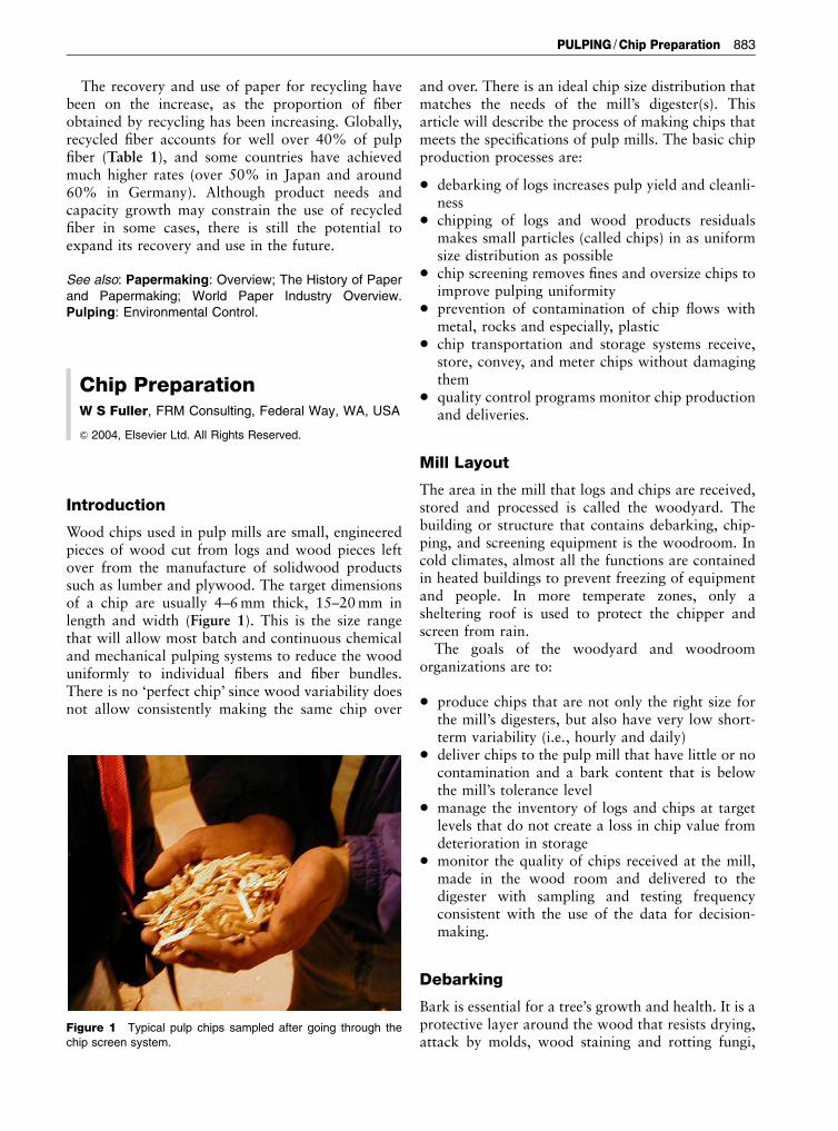
The basic chipping mechanism is a sharp knifepassing through the wood, cutting across the grain(Figure 6). There is first a cutting action and as theknife continues to move into the wood a shearingaction that pops off chips. This continues until theknife has cut completely through the log or piece ofwood when the next knife begins its cut. Chippershave multiple knives mounted on a disk or a drum.The disk chipper is the most common (Figure 7). Aslot is cut radially through the disk so that the chipswill exit from the back of the disk after being cut.The knives are mounted at each of these slots with aclamp mounting or a face mounting (Figure 8).
Figure 4 Long-log drum debarkers in an area with cold climate
where equipment must be enclosed for winter operation.
Figure 5 Sawmill chipper infeed. Vibratory conveyors are
commonly used to convey sawmill waste to chippers. The size
and shape of sawmill by-products varies widely. Some flows are
relatively uniform (a) while others contain long slabs, trim blocks,
and chip screen oversize (b). uniform sawmill chipper feed
material produces more uniform chips.
PULPING /Chip Preparation 885
Awoodroom chipper infeed system has these basicparts: (1) an infeed conveyor moves the logs fromdebarking to the chipper; it is usually a heavy linkchain, heavy-duty rubber belt conveyors or acombination of the two; (2) the infeed chute guidesthe wood from the conveyor to (3) the chipper spoutat the disk face. The chute is commonly at a38-degree angle to the disk. The chute can beoriented to feed the wood by gravity or pulled inhorizontally by the knives (Figure 9).
A disk chipper has 4–12 clamp-mounted knivespositioned radially along slots that pass through thechipper disk. The chips will go through the disk afterthe knife cuts them off the log. Mounted on the backof the chipper disk are fanlike blades that catch thechips and blow them out of the top of the chipperhood. Without these blades, the chips fall onto aconveyor below the chipper. This is a bottomdischarge compared to the overhead or blowndischarge. The blades often have protrusions that
break up the ribbon or card of chips that passthrough the disk.
The layout of sawmill residual chippers is quitesimilar to a woodroom except that the materialchipped is much smaller and has a wide variety ofsizes (Figure 5). Sawmill chipper infeeds can be ateither a right angle to the chipper shaft or as in somenewer sawmill systems, the disk is tilted over theinfeed chute, exerting more pull-in and hold-downforces on sawmill residuals or small logs.
Chipper maintenance is critical in producing anoptimum chip size distribution. Maintaining thedesigned wood to knife interface requires daily,weekly, monthly, and yearly inspections and replace-ment of parts when the wear limits are exceeded.Most wear points can be checked during knifechanges. Chipper knives can wear quickly dependingon the tonnage being chipped, the wood species, themoisture content of the wood, and the amount of rockand metal contaminants that reach the chipper. Simplewear only requires grinding, but grinding donecarefully so that correct knife angles are restoredand metallurgy not altered by overheating. Other keywear areas are the anvils, bed knives, and face plates.Deciding the timing for knife changes depends on therate of wear, the chip quality needs, and the times themill making chips or the woodroom is down forenough time to change knives and inspect the chipperwithout losing production time. Shift changes andmeal breaks are such times. The best way to decidewhen knife changes are needed is by tracking the chipquality. There is a gradual increase in pin chips andfines after a knife change. Depending on the milltolerance for small particles and screen capacity, atonnage or time for knife changes is decided based onchip quality and normal downtime schedules.
A ‘disposable chipper knife’ has become popular inthe last 10 years. These knives have two chippingedges, are in segments about 40–60 cm long and areturned around and relocated on the disk in a patternthat takes advantage of the fact that some zones getmore chipping action than others. Figure 10 shows across-section of a disposable knife, knife holder andmethod of mounting the knife.
Chip Screening and Cleaning
Each pulping system operates best with a specificchip size distribution. Finding that distribution is
Thickness
Chipwidth
Length
Figure 6 Chip cutting action. Only the chipper knife and log are
shown in this drawing of how chips are formed as the knife
passes through a log. The knife cuts the wood off at the desired
length. As the knife continues into the log, it creates shear forces
that pop off a chip at the designed thickness. As chip length
increases, chip thickness also increases.
Figure 7 (a) Horizontal feed disk chipper and approx. 50 cm diameter fiber log; (b) gravity feed disk chipper and 15–20cm diameter
shortwood; (c) horizontal feed disk chipper and approximately 30 cm diameter fiber logs; (d) drive side view of a horizontal feed disk
chipper; note the straight line design from the drum to the feed that eliminates log transfers and plug-ups; (e) chipper operator changing
chipper knives; required safety equipment is being worn and a holding device has been made to reduce the risk of cuts while handling
the newly sharpened knife; (f) the back side of a chipper with card breakers during a knife change; note that the chipper slots have
been lined with a wear plate to prevent disk damage over time.
886 PULPING /Chip Preparation

PULPING /Chip Preparation 887

done with well-planned mill trials, pilot scale trials ata screen manufacturer’s facility, applying informa-tion reported at a conference, literature searches orsimply by observing how the day-to-day operationsfluctuate as chip quality changes. These are listed inthe order of likely success. Given an optimum sizedistribution, a chip screening system can be designedthat meets the mill’s needs. The size fractions mostcommonly removed from a chip flow are over length,over thick, pin chips, and fines (as defined by aChipclass classifier in Figure 11). A well-designedscreen system will remove a target size at highefficiency with low loss of good fiber.
The goal of a pulping system is to make pulp at thehighest yield possible, with low variability the pulpproperties that meet the customer needs. One of themost important contributions a woodroom can maketo pulp mill operations is narrowing the chip sizedistribution after everything has been done to makeoptimum chips in the woodroom, sawmills, satellitechip mills, and plywood plants. Pulp chip screeningequipment is designed specifically to remove and oftenreprocess the extremely large and small chip sizes.
There are several classes of chip screeningequipment:
1. Rotary or gyratory screens. Although the first typeof chip screens to be used in woodrooms, thesescreens are still used alone in sawmills or incombination with some of the more recentscreening concepts in woodrooms (Figure 12).This type of screen segregates chips on the basis oflength or width using flat punched steel plate orwoven wire mesh stacked up to three or more
decks. The circular or elliptical motion of thescreen is in the horizontal plane of the plates. Thetop deck has the largest square, circular, oval, orrectangular openings 40–60mm in diameter,length, or diagonally. Oversize chips are rechippedin a small drum or disc chipper. To remove thesmaller fractions, plates or steel mesh with4–6mm round or square openings are placed inthe bottom deck of the screen. The screeningefficiency of this type of screen is relatively low.Typically, the small fraction removal efficiency is
Figure 8 Woodroom chipper with hood raised for knife
changing. The knife slots and knives reach from the hub to the
edge of the chipper.
Figure 9 Spout location is a key part of chipper design. The
picture shows a chipper spout with the direction of rotation
marked with an arrow. The anvil location is marked with a red
line. This design keeps wood in the lower right corner for uniform
chipping. The sketch shows typical anvil locations of other
designs: (A) a gravity feed with anvils at both of the bottom
edges, (B) a horizontal spout overshaft with a vertical anvil, and
(C) a spout undershaft horizontal feed with bottom and side
anvils. Design (B) is not recommended for roundwood applica-
tions since the wood is lifted up against the force of gravity and
wood (logs or sawmill residuals) do not remain stable.
888 PULPING /Chip Preparation
no more than 50–65%. A rotary/gyratory screen isusually a component of a multiscreen woodroomscreen house and due to its simplicity, is used insawmill and veneer plants.
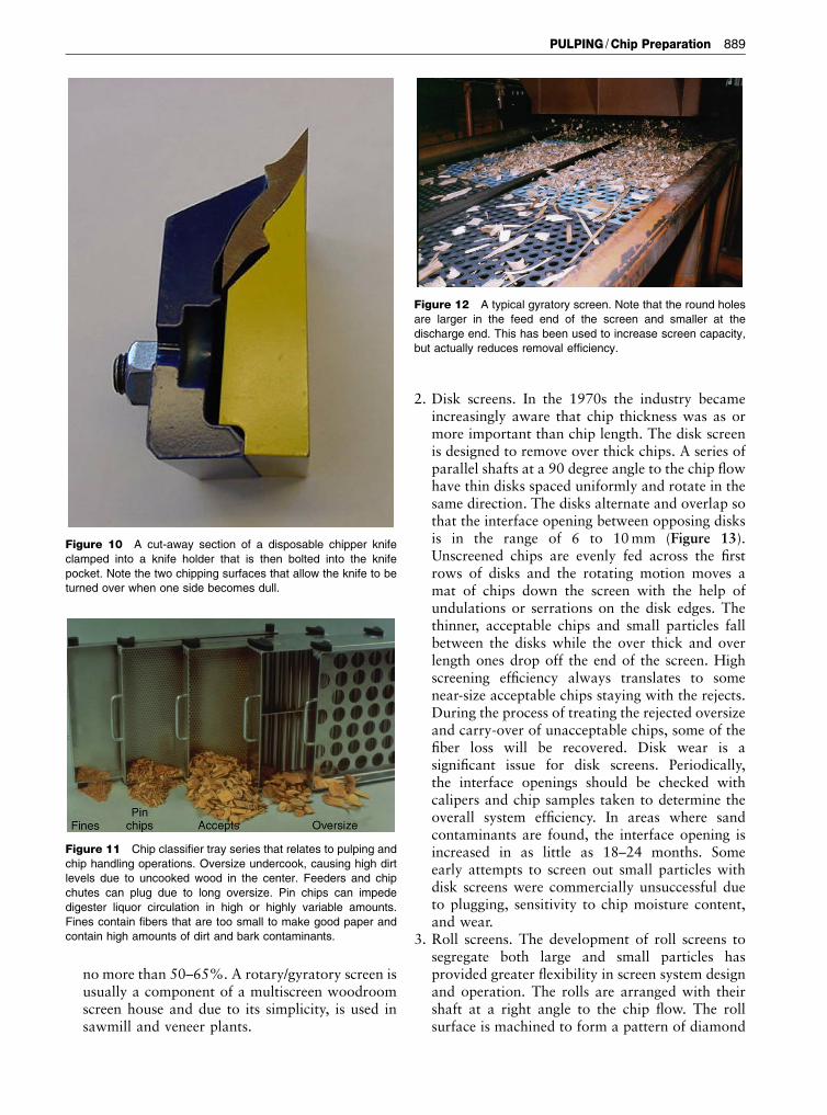
2. Disk screens. In the 1970s the industry becameincreasingly aware that chip thickness was as ormore important than chip length. The disk screenis designed to remove over thick chips. A series ofparallel shafts at a 90 degree angle to the chip flowhave thin disks spaced uniformly and rotate in thesame direction. The disks alternate and overlap sothat the interface opening between opposing disksis in the range of 6 to 10mm (Figure 13).Unscreened chips are evenly fed across the firstrows of disks and the rotating motion moves amat of chips down the screen with the help ofundulations or serrations on the disk edges. Thethinner, acceptable chips and small particles fallbetween the disks while the over thick and overlength ones drop off the end of the screen. Highscreening efficiency always translates to somenear-size acceptable chips staying with the rejects.During the process of treating the rejected oversizeand carry-over of unacceptable chips, some of thefiber loss will be recovered. Disk wear is asignificant issue for disk screens. Periodically,the interface openings should be checked withcalipers and chip samples taken to determine theoverall system efficiency. In areas where sandcontaminants are found, the interface opening isincreased in as little as 18–24 months. Someearly attempts to screen out small particles withdisk screens were commercially unsuccessful dueto plugging, sensitivity to chip moisture content,and wear.
3. Roll screens. The development of roll screens tosegregate both large and small particles hasprovided greater flexibility in screen system designand operation. The rolls are arranged with theirshaft at a right angle to the chip flow. The rollsurface is machined to form a pattern of diamond
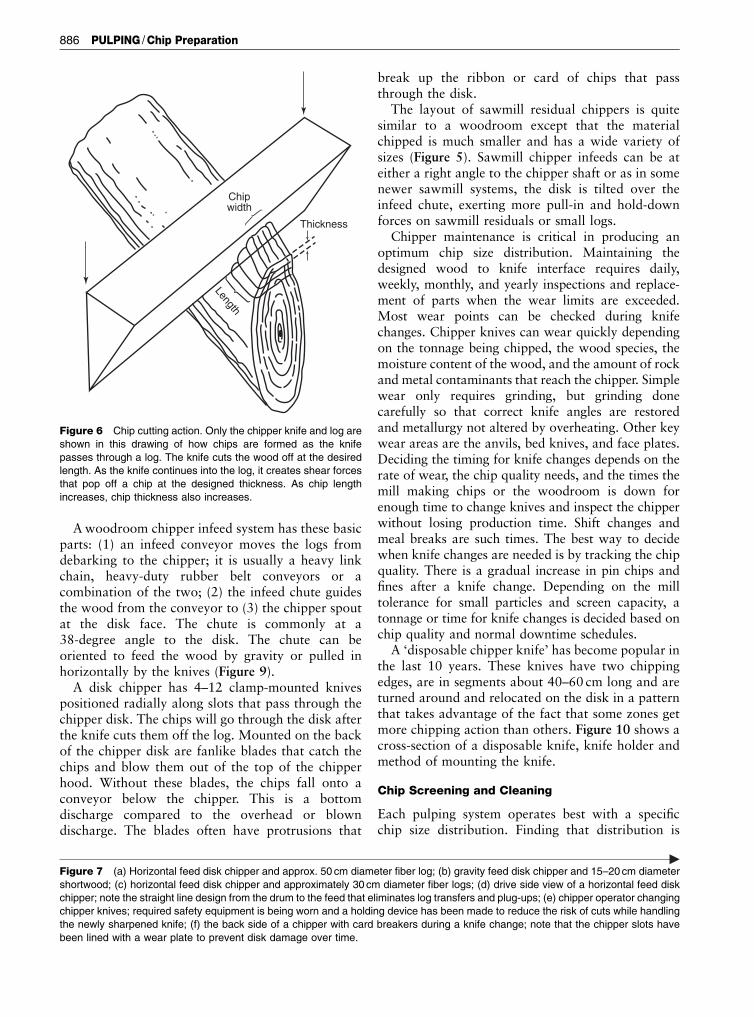
Figure 10 A cut-away section of a disposable chipper knife
clamped into a knife holder that is then bolted into the knife
pocket. Note the two chipping surfaces that allow the knife to be
turned over when one side becomes dull.
Figure 11 Chip classifier tray series that relates to pulping and
chip handling operations. Oversize undercook, causing high dirt
levels due to uncooked wood in the center. Feeders and chip
chutes can plug due to long oversize. Pin chips can impede
digester liquor circulation in high or highly variable amounts.
Fines contain fibers that are too small to make good paper and
contain high amounts of dirt and bark contaminants.
Figure 12 A typical gyratory screen. Note that the round holes
are larger in the feed end of the screen and smaller at the
discharge end. This has been used to increase screen capacity,
but actually reduces removal efficiency.
PULPING /Chip Preparation 889

shaped peaks and valleys (Figure 14). Theinter-roll opening is adjustable from 1.5 to8mm. Thickness screening is possible using theinter-roll opening to reject over thick and overlength chips. The application of roll screens tofines screening and pin chip recovery provides theability to tune the system by adjusting both theroll speed and the spacing. This is particularlyimportant in responding to the higher pin chip andfines content produced by chippers in the wintermonths. Over time, the mix of sawmill chipsupplying a mill will change and with it theaverage size distribution. The adjustability of rollscreens provides the unique opportunity to re-spond to change without the high cost of systemrebuild.
4. Bar and blade screens. Another way to provide aninterface opening through which oversize chipscannot pass is the arrangement of segments of barsor thin blades that oscillate the length of the screento move the chips down the screen and separatethe over length and over thick chips. Wear is muchslower in the bar screen than any other.
Over length, over thick, and accept chips rejectedby thickness screens need treatment before they canbe put back into the chip stream. The composition ofthe over length and over thick chips is dominated bywood knots and the distorted wood aroundbranches. A few wood and pulping experts contendthat the wood in these oversize categories is very highin compression wood and therefore should bediverted into the mill fuel system. Very few millshave analyzed this option and most mills continue toreprocess the oversize material to make it pulpable.The options available for rechipping and oversizetreatment include:
1. Rechippers. Both disk and drum versions ofrechippers are available. Disk rechippers are1–1.5m in diameter. Both horizontal and gravityfeed are common. Tests have shown that it maytake as many as three to five passes before arechipper will reduce some oversize pieces to a sizethat will be accepted in rescreening. Fines produc-tion is increased by rechipping from randomcutting and repeated recycling. The inadequaciesof a rechipper has encouraged the development ofbetter options, particularly since thickness screen-ing implementation began in the 1970s.
2. Chip slicer. A machine that normally makes flakesfor the production of flakeboard has been adaptedto slice over length and over thick chips to athickness that will pulp more easily (Figure 13).Oversize and carried-over accept chips are fed intothe center of a drum surrounded by two con-centric rings. Slicer knives are mounted on theinside of the outer (knife) ring that turns at about150 rpm and in the same direction as the inner oranvil ring. At about 350 rpm, the inner ring anvilssweep the oversize material into the slowermoving knives. A slice is taken at the target chipthickness (6–8mm). As long as a rock or metalcontaminant does not damage the knives, slicershave operated for 6 to 8 weeks before a knifechange was needed. Four weeks is about average.
3. Chip crackers or conditioners. The poor pulp-ability of oversize material is due to the inabilityof pulping liquor to penetrate the chip. Inlaboratory studies, it has been observed that largechips that have partially separated during chip-ping will pulp almost as well as accept chips. Itfollows that if fissures can be created in oversizechips, liquor penetration should be sufficient toachieve pulping. This has been commercialized inchip crushers or conditioners (Figure 14). Theoversize chips drop through the nip between twolarge rolls turning toward each other. There ispressure applied to prevent the nip from opening
Figure 13 Chip slicing. The two rings in the slicer rotate in the
same direction, but the inside ring brings the chips to the knife at
a faster speed than the knife ring is rotating.
890 PULPING /Chip Preparation

when several chips go through at the same time.There is less maintenance since there are no knivesto sharpen. The roll surface metallurgy resistsabrasion and the occasional wrench. As withchippers and slicers, there needs to be protectionfrom the occasional tramp metal and rocks thatfind their way into chip supplies.
Wear and equipment damage is a major problem inrechipping, slicing, and crushing oversize chips. Rocksand metal debris are particularly troublesome. Sinceboth of these materials sink in water, running theoversize through a chip washer or settling basin willeliminate this problem. Sand and grit can be removedin a chip washer in much the same way as rocks.Mechanical pulping systems almost always have chipwashers to reduce wear in the primary refiners.
In regions where freezing conditions preclude theuse of water as a separation medium, air density
separators have been highly successful. The oversizechips are fed into a vertical pipe that contains upwardflowing air from a blower system. By adjusting the airflow, denser rock and metal debris will fall out of theoversize chip flow onto a conveyor belt below whilethe less dense wood will rise and be caught in acyclone feeding a slicer, chip conditioner, or cracker.
There are other types of contaminants that must becontrolled in the mill area to prevent paper down-grade due to spots and holes in the pulp sheet.Grease, oil, char, paint, rubber, and plastic are someof the most common contaminants. The mostdifficult of these is plastic contamination. Onceplastic is in the pulp, there are very few methods ofremoving it economically. Plastic is introduced intochip flows primarily by people who do not under-stand the consequences of disposing of things like asandwich bag, ear plugs, a candy wrapper, and otherdebris into a chip truck or onto a conveyor. After
Figure 14 Chip cracker or chip conditioner. (a) One of the pair of rolls in the system; (b) close-up of the inter-roll opening;
(c) examples of oversize after going through the roll opening. Note how the large chips are fissured by the crushing force and the roll
surface.
PULPING /Chip Preparation 891
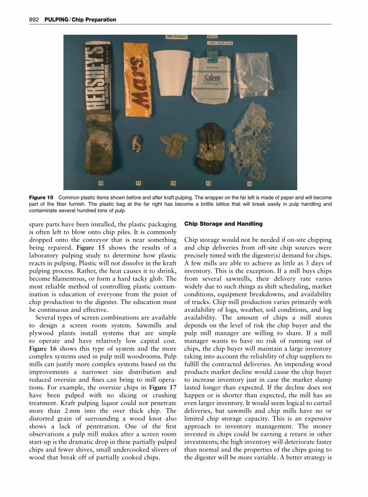
spare parts have been installed, the plastic packagingis often left to blow onto chip piles. It is commonlydropped onto the conveyor that is near somethingbeing repaired. Figure 15 shows the results of alaboratory pulping study to determine how plasticreacts in pulping. Plastic will not dissolve in the kraftpulping process. Rather, the heat causes it to shrink,become filamentous, or form a hard tacky glob. Themost reliable method of controlling plastic contam-ination is education of everyone from the point ofchip production to the digester. The education mustbe continuous and effective.
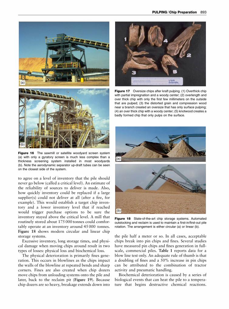
Several types of screen combinations are availableto design a screen room system. Sawmills andplywood plants install systems that are simpleto operate and have relatively low capital cost.Figure 16 shows this type of system and the morecomplex systems used in pulp mill woodrooms. Pulpmills can justify more complex systems based on theimprovements a narrower size distribution andreduced oversize and fines can bring to mill opera-tions. For example, the oversize chips in Figure 17have been pulped with no slicing or crushingtreatment. Kraft pulping liquor could not penetratemore than 2mm into the over thick chip. Thedistorted grain of surrounding a wood knot alsoshows a lack of penetration. One of the firstobservations a pulp mill makes after a screen roomstart-up is the dramatic drop in these partially pulpedchips and fewer shives, small undercooked slivers ofwood that break off of partially cooked chips.
Chip Storage and Handling
Chip storage would not be needed if on-site chippingand chip deliveries from off-site chip sources wereprecisely timed with the digester(s) demand for chips.A few mills are able to achieve as little as 3 days ofinventory. This is the exception. If a mill buys chipsfrom several sawmills, their delivery rate varieswidely due to such things as shift scheduling, marketconditions, equipment breakdowns, and availabilityof trucks. Chip mill production varies primarily withavailability of logs, weather, soil conditions, and logavailability. The amount of chips a mill storesdepends on the level of risk the chip buyer and thepulp mill manager are willing to share. If a millmanager wants to have no risk of running out ofchips, the chip buyer will maintain a large inventorytaking into account the reliability of chip suppliers tofulfill the contracted deliveries. An impending woodproducts market decline would cause the chip buyerto increase inventory just in case the market slumplasted longer than expected. If the decline does nothappen or is shorter than expected, the mill has aneven larger inventory. It would seem logical to curtaildeliveries, but sawmills and chip mills have no orlimited chip storage capacity. This is an expensiveapproach to inventory management. The moneyinvested in chips could be earning a return in otherinvestments; the high inventory will deteriorate fasterthan normal and the properties of the chips going tothe digester will be more variable. A better strategy is
Figure 15 Common plastic items shown before and after kraft pulping. The wrapper on the far left is made of paper and will become
part of the fiber furnish. The plastic bag at the far right has become a brittle lattice that will break easily in pulp handling and
contaminate several hundred tons of pulp.
892 PULPING /Chip Preparation
to agree on a level of inventory that the pile shouldnever go below (called a critical level). An estimate ofthe reliability of sources to deliver is made. Also,how quickly inventory could be replaced if a largesupplier(s) could not deliver at all (after a fire, forexample). This would establish a target chip inven-tory and a lower inventory level that if reachedwould trigger purchase options to be sure theinventory stayed above the critical level. A mill thatroutinely stored about 175 000 tonnes could comfor-tably operate at an inventory around 45000 tonnes.Figure 18 shows modern circular and linear chipstorage systems.
Excessive inventory, long storage times, and physi-cal damage when moving chips around result in twotypes of losses: physical loss and biochemical loss.
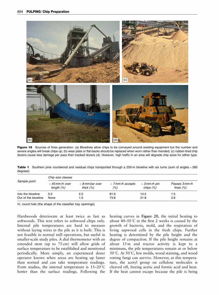
The physical deterioration is primarily fines gene-ration. This occurs in blowlines as the chips impactthe walls of the blowline at repeated bends and sharpcorners. Fines are also created when chip dozersmove chips from unloading systems onto the pile andlater, back to the reclaim pit (Figure 19). Becausechip dozers are so heavy, breakage extends down into
the pile half a meter or so. In all cases, acceptablechips break into pin chips and fines. Several studieshave measured pin chips and fines generation in full-scale, commercial piles. Table 1 reports data for ablow line test only. An adequate rule of thumb is thata doubling of fines and a 50% increase in pin chipscan be attributed to the combination of tractoractivity and pneumatic handling.
Biochemical deterioration is caused by a series ofbiological events that can heat the pile to a tempera-ture that begins destructive chemical reactions.
Figure 16 The sawmill or satellite woodyard screen system
(a) with only a gyratory screen is much less complex than a
thickness screening system installed in most woodyards
(b). Note the aerodynamic separator up-draft tubes can be seen
on the closest side of the system.
Figure 17 Oversize chips after kraft pulping. (1) Overthick chip
with partial impregnation and a woody center; (2) overlength and
over thick chip with only the first few millimeters on the outside
that are pulped; (3) the distorted grain and compression wood
near a branch created an oversize that has only surface pulping;
(4) an over thick chip with a woody center; (5) knotwood creates a
badly formed chip that only pulps on the surface.
Figure 18 State-of-the-art chip storage systems. Automated
outstocking and reclaim is used to maintain a first-in/first-out pile
rotation. The arrangement is either circular (a) or linear (b).
PULPING /Chip Preparation 893
Hardwoods deteriorate at least twice as fast assoftwoods. This text refers to softwood chips only.Internal pile temperatures are hard to measurewithout laying wires in the pile as it is built. This isnot feasible in normal mill operations, but useful insmaller-scale study piles. A dial thermometer with anextended stem (up to 75 cm) will allow grids ofsurface temperature to be established and monitoredperiodically. More simply, an experienced dozeroperator knows when areas are heating up fasterthan normal and can take temperature readings.From studies, the internal temperature is 15–201Chotter than the surface readings. Following the
heating curves in Figure 20, the initial heating toabout 40–501C in the first 2 weeks is caused by thegrowth of bacteria, mold, and the respiration ofliving sapwood cells in the fresh chips. Furtherheating is determined by the pile height and thedegree of compaction. If the pile height remains atabout 15m and tractor activity is kept to aminimum, the pile temperatures remain at or below501C. At 501C, few molds, wood staining, and woodrotting fungi can survive. However, at this tempera-ture, the acetyl group on cellulose molecules iscleaved off, freeing acetic and formic acid and heat.If the heat cannot escape because the pile is being
Figure 19 Sources of fines generation. (a) Blowlines allow chips to be conveyed around existing equipment but the number and
severe angles will break chips up; (b) wear plate or flat-backs should be replaced when worn rather than mended; (c) rubber-tired chip
dozers cause less damage per pass than tracked dozers (d). However, high traffic in an area will degrade chip sizes for either type.
Table 1 Southern pine roundwood and residual chips transported through a 250-m blowline with six turns (sum of angles¼ 280
degrees)
Chip size classes
Sample point þ 45mmrh over
length (%)
þ 8mmbar over
thick (%)
þ7mmrh accepts
(%)
þ3mmrh pin
chips (%)
Passes 3mmrh
fines (%)
Into the blowline 0.2 2.2 81.6 14.5 1.5
Out of the blowline None 1.0 73.6 21.8 3.6
rh, round hole (the shape of the classifier tray openings).
894 PULPING /Chip Preparation
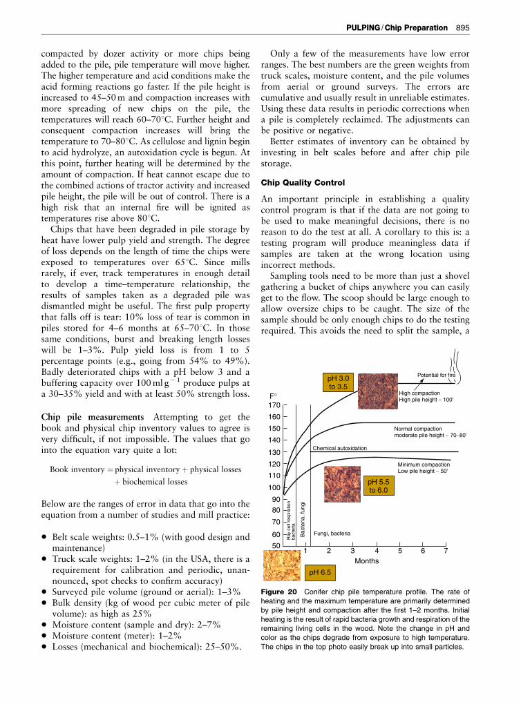
compacted by dozer activity or more chips beingadded to the pile, pile temperature will move higher.The higher temperature and acid conditions make theacid forming reactions go faster. If the pile height isincreased to 45–50m and compaction increases withmore spreading of new chips on the pile, thetemperatures will reach 60–701C. Further height andconsequent compaction increases will bring thetemperature to 70–801C. As cellulose and lignin beginto acid hydrolyze, an autoxidation cycle is begun. Atthis point, further heating will be determined by theamount of compaction. If heat cannot escape due tothe combined actions of tractor activity and increasedpile height, the pile will be out of control. There is ahigh risk that an internal fire will be ignited astemperatures rise above 801C.
Chips that have been degraded in pile storage byheat have lower pulp yield and strength. The degreeof loss depends on the length of time the chips wereexposed to temperatures over 651C. Since millsrarely, if ever, track temperatures in enough detailto develop a time–temperature relationship, theresults of samples taken as a degraded pile wasdismantled might be useful. The first pulp propertythat falls off is tear: 10% loss of tear is common inpiles stored for 4–6 months at 65–701C. In thosesame conditions, burst and breaking length losseswill be 1–3%. Pulp yield loss is from 1 to 5percentage points (e.g., going from 54% to 49%).Badly deteriorated chips with a pH below 3 and abuffering capacity over 100ml g� 1 produce pulps ata 30–35% yield and with at least 50% strength loss.
Chip pile measurements Attempting to get thebook and physical chip inventory values to agree isvery difficult, if not impossible. The values that gointo the equation vary quite a lot:
Book inventory ¼ physical inventoryþ physical losses
þ biochemical losses
Below are the ranges of error in data that go into theequation from a number of studies and mill practice:
* Belt scale weights: 0.5–1% (with good design andmaintenance)
* Truck scale weights: 1–2% (in the USA, there is arequirement for calibration and periodic, unan-nounced, spot checks to confirm accuracy)
* Surveyed pile volume (ground or aerial): 1–3%* Bulk density (kg of wood per cubic meter of pile
volume): as high as 25%* Moisture content (sample and dry): 2–7%* Moisture content (meter): 1–2%* Losses (mechanical and biochemical): 25–50%.
Only a few of the measurements have low errorranges. The best numbers are the green weights fromtruck scales, moisture content, and the pile volumesfrom aerial or ground surveys. The errors arecumulative and usually result in unreliable estimates.Using these data results in periodic corrections whena pile is completely reclaimed. The adjustments canbe positive or negative.
Better estimates of inventory can be obtained byinvesting in belt scales before and after chip pilestorage.
Chip Quality Control
An important principle in establishing a qualitycontrol program is that if the data are not going tobe used to make meaningful decisions, there is noreason to do the test at all. A corollary to this is: atesting program will produce meaningless data ifsamples are taken at the wrong location usingincorrect methods.
Sampling tools need to be more than just a shovelgathering a bucket of chips anywhere you can easilyget to the flow. The scoop should be large enough toallow oversize chips to be caught. The size of thesample should be only enough chips to do the testingrequired. This avoids the need to split the sample, a
170
160
150
140
130
120
100
90
80
70
60
50
110
1 2 3Months
4 5 6 7
Potential for fire
High compactionHigh pile height − 100'
Normal compactionmoderate pile height − 70−80'
Minimum compactionLow pile height − 50'
Chemical autoxidation
Fungi, bacteriaBac
teria
, fun
gi
Ray
cel
l res
pira
tion
bact
eria
F°
pH 3.0to 3.5
pH 5.5to 6.0
pH 6.5
Figure 20 Conifer chip pile temperature profile. The rate of
heating and the maximum temperature are primarily determined
by pile height and compaction after the first 1–2 months. Initial
heating is the result of rapid bacteria growth and respiration of the
remaining living cells in the wood. Note the change in pH and
color as the chips degrade from exposure to high temperature.
The chips in the top photo easily break up into small particles.
PULPING /Chip Preparation 895

process that introduces as much or more error asincorrect sampling. If special testing will require morethan the normal scoop full, it is better to collect twoscoop fulls and composite them for testing. If a barrelof chips is needed to send to a research laboratory, itshould be gathered over a full day to avoid the risk ofgetting chips from one supplier or type of chip that isonly a part of the total chip consumption.
After deciding what chip flows need to be sampled,sampling points must be located where they are safeto access, easy to get to, and allow a sample scoop tobe inserted and so that chips can be gathered thatrepresent the entire cross-section of the flow. Beltconveyor transfer points are an ideal place to do this.In most cases, there is access to the entire flow as itfalls from one conveyor to the next. If not, a door canbe cut in the hood. Access is preferable with the flowof chip coming toward the sampling point. Thescoop is inserted upside-down, pushed all the waythrough the flow, turned over and quickly drawn outto take the sample from the entire depth of chip flow.A permanently mounted tube sampler replicates thissampling process. Figure 21 shows several standardand tube sampling applications. There are othertypes of samplers that allow representative samplingof truck deliveries. Since installing samplers is almostalways an add-on to existing systems, there are fewthat are alike. There are commercial samplersavailable that can be adapted to many situations.
A sample taken from the top of a moving belt orthe top of a delivery truck or rail car will alwayscontain fewer fines than a representative sample. Assoon as chips are moved along a belt, in a rail car ortruck bed, fines immediately begin to percolatedownward. Similarly, a sample removed from thelower part of a rail car or chip trailer will be biasedwith more fines that have moved down the chip bed.Sometimes, a sample taken correctly at a transferpoint is not representative. The likely cause is severaltypes of chip flows joining together and one of thembeing loaded toward one side of the conveyor. Theaddition of cracked or conditioned oversize back intothe accept flow often comes down a chute, depositingto one side of the belt.
The most widely used test methods to trackwoodroom and supplier quality performance are:
1. Moisture content or %OD (percentage of oven-dry solids) solids. This is used to convert the greenweight of chip deliveries to a dry weight. Moisturecontents of sawmill and plywood plant residuals,woodroom production, and wood chipped thin-nings can differ by as much as 15–20% points.Depending on the mix of wood being used, a pulpmill may be buying a lot of water at chip prices.
Factors that influence the reliability of this testwere listed earlier.
2. Bark content. The test is a tedious separation of allbark and wood. Optical methods of testing barkhave not been successful. To speed the test up,some mills only measure bark in the acceptsfraction. This underestimates the actual barkcontent since up to half of the bark breaks downinto small pieces. The need for precise estimates is
Figure 21 Options for chip sampling. (a) Manual sampling at a
belt transfer point using a scoop sized to collect enough chips for
the tests being done; (b) an automatic sampler using a bucket
mounted on a swinging arm for truck dump sampling; (c) a tube
sampler and sample port at a chip screen system to remove chips
after screening.
896 PULPING /Chip Preparation
diminishing as pulp bleaching technology hasmade headway in controlling pulp dirt associatedwith bark that was not removed in sawmill orwoodroom debarking. A survey of mills confirmedthat the specification for bark has been increasingin recent years from less than 0.5% to 1–2%.
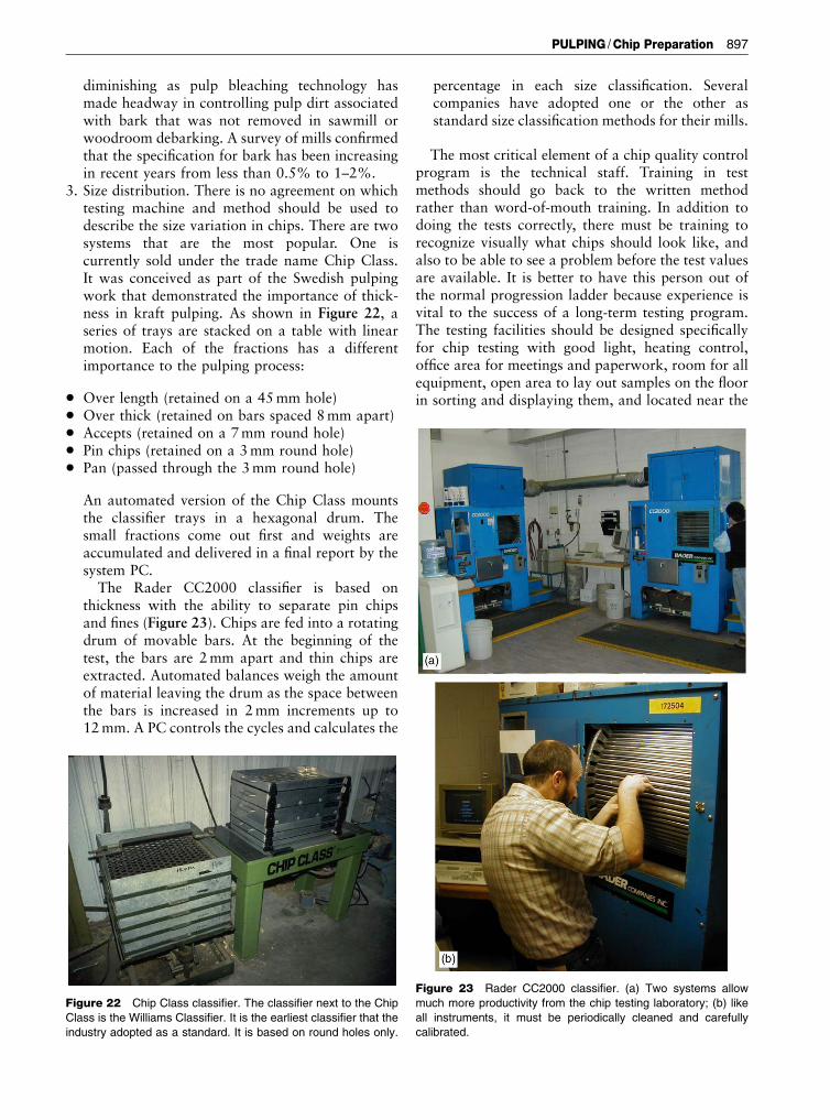
3. Size distribution. There is no agreement on whichtesting machine and method should be used todescribe the size variation in chips. There are twosystems that are the most popular. One iscurrently sold under the trade name Chip Class.It was conceived as part of the Swedish pulpingwork that demonstrated the importance of thick-ness in kraft pulping. As shown in Figure 22, aseries of trays are stacked on a table with linearmotion. Each of the fractions has a differentimportance to the pulping process:
* Over length (retained on a 45mm hole)* Over thick (retained on bars spaced 8mm apart)* Accepts (retained on a 7mm round hole)* Pin chips (retained on a 3mm round hole)* Pan (passed through the 3mm round hole)
An automated version of the Chip Class mountsthe classifier trays in a hexagonal drum. Thesmall fractions come out first and weights areaccumulated and delivered in a final report by thesystem PC.
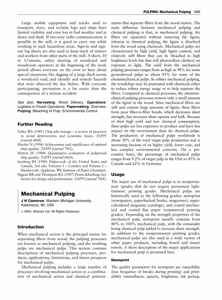
The Rader CC2000 classifier is based onthickness with the ability to separate pin chipsand fines (Figure 23). Chips are fed into a rotatingdrum of movable bars. At the beginning of thetest, the bars are 2mm apart and thin chips areextracted. Automated balances weigh the amountof material leaving the drum as the space betweenthe bars is increased in 2mm increments up to12mm. A PC controls the cycles and calculates the
percentage in each size classification. Severalcompanies have adopted one or the other asstandard size classification methods for their mills.
The most critical element of a chip quality controlprogram is the technical staff. Training in testmethods should go back to the written methodrather than word-of-mouth training. In addition todoing the tests correctly, there must be training torecognize visually what chips should look like, andalso to be able to see a problem before the test valuesare available. It is better to have this person out ofthe normal progression ladder because experience isvital to the success of a long-term testing program.The testing facilities should be designed specificallyfor chip testing with good light, heating control,office area for meetings and paperwork, room for allequipment, open area to lay out samples on the floorin sorting and displaying them, and located near the
Figure 22 Chip Class classifier. The classifier next to the Chip
Class is the Williams Classifier. It is the earliest classifier that the
industry adopted as a standard. It is based on round holes only.
Figure 23 Rader CC2000 classifier. (a) Two systems allow
much more productivity from the chip testing laboratory; (b) like
all instruments, it must be periodically cleaned and carefully
calibrated.
PULPING /Chip Preparation 897

woodroom. The chip testing position should never benear entry level and the lead tester should be part ofthe woodroom operating team.
A chip quality report should be more than a stackof computer printouts. In order to be able to seetrends and changes, key data should be presented ingraphs that are easily interpreted. The graphicalreports should be made visible to everyone workingin the woodyard and woodroom and discussed withsuppliers. With the available spreadsheet graphicsprograms available, graphing of data should bestandard practice. Visual displays focusing on aspectsof quality should be developed so that those whodeliver chips can know what they should look like,too (Figure 24).
Woodyard and Woodroom Safety
Woodyard safety is a critical function for everywoodyard employee. Whenever in the operating area,
personal protective equipment must be consistentlyused to reduce the risk of injury. The noise levelsaround operating debarking, chipping, and screeningsystems is well above the level that causes permanenthearing loss. Safety glasses with side shields arealways needed to prevent wood dust and debris andflying objects from damaging eyes. Hard hats preventinjury from falling objects or head injury in areaswith low headroom. When cleaning up dusty areas,respiratory masks will prevent inhalation of smallwood particles that can accumulate in the lungs andcause long-term health problems. Some people aresensitive to the molds that grow in enclosed anddamp areas such as conveyor tunnels. These peopleshould not be assigned work in the contaminatedareas. Equipment that is subject to high stress andimpact loads need to be examined periodically. Alogjam in the chipper infeed must be cleared toresume production. It is essential that no person placehimself or herself at risk of falling into an operatingchipper infeed at any time and particularly in thissituation. Mechanical systems such as the one shownin Figure 25 are invaluable in this instance. The ramsare pushed in and out to dislodge the jammed logs. Ifno such device is installed on a chipper, the chippermust be stopped with the use of a disk brake andlocked out and tagged out to prevent starting whenworkers are clearing the chute. Only then shouldwoodroom operators get near the logs in the infeed toattach grapples attached to overhead winches. Logtongs should be attached with both a shackle and arestraining chain in the event the shackle breaks.Normal required lock-out and tag-out procedures arefollowed to return the chipper to service. Chipperknives are very sharp and should be handled withsteel reinforced gloves.
Figure 24 Chip quality education tool. A display of chip quality
definitions, impact on the mill, and real examples of each material
type will help suppliers, truck drivers, and others who work with
chips to understand the importance of chip quality. Customers of
the pulp and paper products will appreciate this example of
making chip quality a high priority. The one category missing in
this display is emphasis on the requirement to eliminate
contamination of chips with metal, plastic, dirt, and rocks.
Figure 25 Rams that can be pushed into the chipper infeed to
dislodge logs that sometimes frequently plug the spout. This is
much safer than trying to break up the jam with pike poles or log
tongs and takes less time.
898 PULPING /Chip Preparation
Large mobile equipment and trucks used totransport, store, and reclaim logs and chips havelimited visibility and even less in bad weather and atdawn and dusk. If two-way radio communication ispossible in the mill, it is good to carry one whileworking in such hazardous areas. Sign-in and sign-out log sheets are also used to keep track of visitorsand workers from other parts of the mill. A short, 10to 15minute, safety meeting of woodyard andwoodroom operators at the beginning of the workperiod allows everyone on the crew to hear aboutspecial situations, like digging of a large ditch acrossa woodyard road, and identify and remedy hazardsthat were observed the day before. With everyoneparticipating, prevention is a lot easier than theconsequences of a serious accident.
See also: Harvesting: Wood Delivery. Operations:Logistics in Forest Operations. Papermaking: Overview.Pulping: Bleaching of Pulp; Environmental Control.
Further Reading
Fuller WS (1985) Chip pile storage – a review of practicesto avoid deterioration and economic losses. TAPPIJournal 68(8).
Hartler N (1996) Achievement and significance of optimalchip quality. TAPPI Journal 79(2).
Hatton JV (1984) Quantitative evaluation of pulpwoodchip quality. TAPPI Journal 60(4).
Isenberg IH (1980) Pulpwoods of the United States andCanada, 3rd edn. Volumes 1 – Conifers and Volume 2 –Hardwoods. Appleton, WI: Institute of Paper Chemistry.
Piggott RR and Thompson RA (1987) Drum debarking: keyfactors for design and performance. TAPPI Journal 70(8).
Mechanical PulpingJ H Cameron, Western Michigan University,Kalamazoo, MI, USA
& 2004, Elsevier Ltd. All Rights Reserved.
Introduction
When mechanical action is the principal means forseparating fibers from wood, the pulping processesare known as mechanical pulping, and the resultingpulps are mechanical pulps. This section containsdescriptions of mechanical pulping processes, pro-ducts, applications, limitations, and future prospectsfor mechanical pulps.
Mechanical pulping includes a large number ofprocesses involving mechanical action or a combina-tion of mechanical action and chemical pretreat-
ments that separate fibers from the wood matrix. Themain difference between mechanical pulping andchemical pulping is that, in mechanical pulping, thefibers are separated without removing the lignin,whereas in chemical pulping, the lignin is dissolvedfrom the wood using chemicals. Mechanical pulps arecharacterized by high yield, high lignin content, andrelatively stiff fibers that can be bleached to highbrightness levels but that will photoyellow (darken) onexposure to light. The yield from the mechanicalpulping processes ranges from as high as 98% for somegroundwood pulps to about 85% for some of thechemimechanical pulps. In refiner mechanical pulping,the woodchips may be pretreated with chemicals eitherto reduce refiner energy usage or to help separate thefibers. Compared to chemical processes, the chemime-chanical pulping processes remove only a small amountof the lignin in the wood. Since mechanical fibers arestiff and contain large amounts of lignin, these fibersform poor fiber-to-fiber bonds, which decreases sheetstrength, but increases sheet opacity and bulk. Becauseof their high yield and low chemical consumption,these pulps are less expensive to produce and have lessimpact on the environment than do chemical pulps.The production of mechanical pulps worldwide isabout 30% of the total virgin pulp production and isincreasing because of its higher yield, lower cost, andless complex environmental concerns. On a per-country basis, the percentage of mechanical pulpsranges from 9.2% of virgin pulp in the USA to 45% inCanada and 62% in Germany.
Usage
The major use of mechanical pulps is in nonperma-nent (grades that do not require permanent light-fastness) printing grades. Mechanical pulps arehistorically used in the following grades: newsprint(newspapers, paperbacked books, magazines), super-calendered magazine (catalogs), and coated mechan-ical and coated fine paper (commercial printinggrades). Depending on the strength properties of themechanical pulp, newsprint usually contains from80% to 100% mechanical pulp, with the remainderbeing chemical pulp added to increase sheet strength.In addition to the nonpermanent printing grades,mechanical pulps are also used in a wide variety ofother paper products, including board and tissue/towels. A short description of the major applicationsfor mechanical pulp is presented here.
Newsprint
The quality parameters for newsprint are runnability(low frequency of breaks during printing) and print-ability (smoothness, opacity, brightness, ink pickup,
PULPING /Mechanical Pulping 899