
A micropillar-based on-chip system for continuous force measurement of C. elegans
Upload
independentresearcherCategory
view
0download
0
PRESSA: from system to chip
History
IT-ACS Ltd
by Igor Schagaev
HW SSWTheory Theory
Design for Reliability - "From Chip to System”
Greenwich Uni 05.12.13

History: Theory
Theory of fault tolerant computer design 1978-till now !
Theory of active system safety, active system control 1989-till now !
Design, development and reliability modelling of fault tolerant RAM: New triplicated memory, sliding reserve RAM, des., dev., done 1999
!Processors - concept, design, development, simulation, assembler, language run-time
system, prototyping and reliability analysis since 1983 till now (see ERA…) !
System software language and run-time system design and development for reconfigurable architectures (see PRESSA below and book 2013)…
!Method of active system safety and system control (since 1984, UK patent 2007)
! details: http://www.researchgate.net/profile/Igor_Schagaev/?ev=hdr_xprf
IT-ACS Ltd
by Igor Schagaev

History: Hardware
IT-ACS Ltd
by Igor Schagaev
!RELIABLE DESIGN FROM RELIABLE COMPONENT
24 NODE FT NAVY COMPUTER BASED ON LSI11-23, 1978-1982
64 PE FAULT TOLERANT M-SIMD BASED ON AM2901 TILL 1987
FAULT TOLERANT AVIONICS FOR SUKHOY Active safety system for aircraft with dual Motorola 68020, fault tolerant
memory for applications (41 chip of SRAM) and new tripled memory together with flight data recorder with unique thermo-resistant system -
developed, prototyped and tested. Completed 1994
ERRIC Embedded recoverable reduced instruction computer, designed and
prototyped in 1998-2009 before and within FP6 ONBASS project (FP6). Malfunction tolerance and rigorous design enabled to achieve fault
tolerance with 12% structural redundancy and zero time redundancy. ERRIC requires 6.5 times less power than ARM, has similar performance,
and… 104 more reliable… 1998-up to now
NEXT STOP - NEW ERA Idea to combine ERRIC and ITACS memory designs to make fault
tolerant reconfigurable architecture on a wafer became known as ERA (evolving reconfigurable architecture). In progress !
PRESSA: Perfomance-, Reliability-, Energy- Smart System Architecture Multi-chip development of ERA… Started in 2009 !
more details: www.it-acs.co.uk

from system to chip: WHY?
IT-ACS Ltd
by Igor Schagaev
Theory, again of system software
support of hardware efficiency…
!see for example: www.it-acs.co.uk
!more is needed…
HW
Software
HW Software
HW
System Software
Application Software
from system to chip: concept first
IT-ACS Ltd
by Igor Schagaev
FP7-ICT-2013-4 PRESSA
© PRESSA consortium 2012 6
PRESSA rigorously defines reconfigurability and possible applications, including fault tolerance, or performance (the latter by means of a multi-core approach) or energy-wise functioning. Note that PRE- features of the system introduced and supported by design.
As a third optimization axis beyond performance and reliability PRESSA aims to facilitate advanced resource management to reduce power consumption in battery driven applications. High degree of reconfigurability combined with that fact that we are designing an entire new computing paradigm consisting of processor hardware, memory architecture, a modelling language, a programming language, and the run time system opens up new dimensions of dynamic power management.
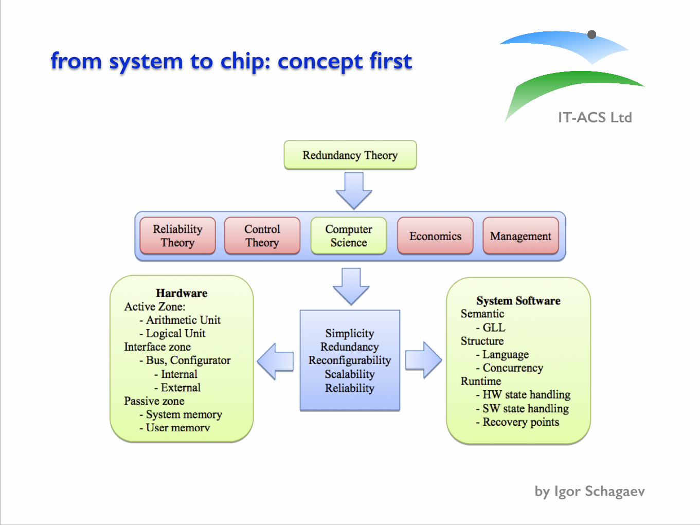
The PRESSA project is based on previous theoretical results in study of redundancy classification and management introduced in late 80’s [SCH86-11]. PRESSA scientific development pursues redundancy and reconfigurability study further as shown below on Figure 1 and explained on Table 1 below:
Figure 1 PRESSA areas of theoretical and technological contribution
“Holistic” principles of the Table 1 will be pursued through the whole design process of theoretical, algorithmic and further hardware and system software implementations. Reasoning why it is required is presented in the Table 1 below. Left and right boxes of Figure 1 require some comments. From the point of view of information transformation one might consider two areas of hardware: where information is transformed – further called active zone and area where information is stored – passive zone.

from system to chip: principles
IT-ACS Ltd
by Igor Schagaev
FP7-ICT-2013-4 PRESSA
© PRESSA consortium 2012 7
The interconnection of these zones is the interfacing zone. In principle, all three zones have to be reconfigurable for their own purposes as well as other zones requests. Interactions of zones define reconfigurability and flexibility of the architecture.
Therefore proposed project defines essential features and their impact on basic system elements when exceptional system reconfigurability is required.
Hardware reconfigurability will be reflected and supported at the system software level by language and run-time system.
Table 1: PRESSA holistic design principles and reasoning
Historically computer technologies were not addressing potentially work of computer within connected computer (CC) framework; this reduces our expectations in addressing distributed computing aspect by-design. Attempts such as transputer prove also that introducing of distributiveness into CC is pretty challenging and not easy task. CC systems such as Internet and Ethernet are expanding enormously in terms of data transfer, video, audio, e-mails.
There is a visible shift of distributed computing paradigm toward distributed databases, financial services such as ATM, solution of distributable large-scale tasks using connected computers as so-called cloud computing. Note here only that efficiency of large-scale applications such as cloud computing depends on the algorithm backbones - graphs of data, control and address dependencies [2] and their use to prepare algorithms for distributed computing.
Simplicity
Complex things tend not to work properly. PRESSA avoids introducing extra hardware and software ‘bells and whistles’ in the architecture to placate history (compatibility with main market players) or conventions (pipelines and caches etc.), and which often adds enormous complexity for very little gain in performance or reliability.
Redundancy Deliberate introduction of hardware and system software redundancy together with monitoring schemes provides the means for PRESSA to use reconfiguration to improve reliability
Reconfigurability PRESSA reconfigurability has three main purposes: performance, reliability and power awareness. Handling reconfigurability using language and run-time support provides unique flexibility in trading of reliability, performance and energy-wise use.
Scalability
Design and development of hardware and software to achieve high reliability, and monitor graceful degradation of hardware in terms of performance and reliability. Active support of reconfiguration is managed in real time by means of control of hardware and system software resources. The software and hardware are both specifically designed to scale up.
Reliability and
fault tolerance
Our approach is to use minimum redundancy by designing the main elements to be as reliable as possible and combine them together with minimum complexity of connections. Redundancy of resources is deliberately introduced, both in hardware and software, and then managed to maximize tolerance to malfunction and permanent faults.
Resource-awareness
Mission critical systems as well as everyday applications may have significant limitations, in terms of hardware (computational and memory) resources and power consumption constraints (e.g. battery life). All of the above features must be taken into account by using systems engineering based on hardware-software co-design.

© IT-ACS
!
P
Performance
E
Energy
R
Reliability
PRE-smart CC
Recoverability?
P, R, E Trading?
FAULT TOLERANCE
Redundancy Reconfigurability Fault model
! Big Q: how much?
PRESSA: from system to chip

PRESSA: from system to chipIT-ACS Ltd
by Igor Schagaev
!for one computer
!for multiprocessor system
Fig. 8. Indicative ERA structure Each element can be turned off individually to decrease power consumption. Note that the structure assumes only one leading element at a time enforced by a “rotation” of the T-logic element. T-logic makes the whole ERA possible to operate until the last soldier stands: i.e. until a single processor, called ERRIC, and a single memory element can communicate (Fig.8).
VI. CONCLUSION AND FUTURE WORK This paper presents concepts and design ideas to cope with
known drawbacks of computer architectures. ERA reconfigurability is represented at the programming language and the run-time system, which will result ultimately in a simple, yet scalable, reliable system.
REFERENCES [1] Goldstine, A. and Goldstine, H. H. (1946) ENIAC, The Electronic
Numerical Integrator. Math Tables and Other Aids to Computation, vol. 1, pp. 97-110
[2] Report R-127 (1947) Whirlwind I Computer Block Diagrams. Everett, R.R., and Swain, F.E. MIT Servomechanisms Laboratory.
[3] Whirlwind I, Master Drawing List And General Rack Layout Of Computer. (1952), MIT, Department of Electrical Engineering, Cambridge.
[4] Smithsonian Institute (1990) Computer history collection http://americanhistory.si.edu/collections/ comphist/
[5] Hofstra University, (1999), History in the Computing Curriculum Appendix 4 1950 – 1959. www.comphist. org/pdfs/CompHist_9812tla4.pdf
[6] Holland, J.H. (1960) Iterative circuit computers, IRE-AIEE-ACM '60 (Western): Papers presented at the May 3-5, 1960, western joint IRE-AIEE-ACM computer conference, San Francisco, California, pp. 259-265, ACM, New York, USA
[7] Newell, A. (1960) A On programming a highly parallel machine to be an intelligent technician, IRE-AIEE-ACM '60 (Western): Papers presented at the May 3-5, 1960, western joint IRE-AIEE-ACM computer conference, May 3-5, pp. 267-282, ACM, New York
[8] Schwartz, E. (1961) An Automatic Sequencing Procedure with Application to Parallel Programming, Journal of the ACM (JACM), v.8 n.4, p.513-537, ACM, New York
[9] Slotnick, D. L., et al. (1962) The SOLOMON Computer, AFIPS '62 (Fall): Proceedings of the December 4-6, 1962, fall joint computer conference, Philadelphia, pp. 97-107, ACM, New York.
[10] Squire, J. S. and Palais, S. M. (1963) Physical and Logical Design of a Highly Parallel Computer, Proc. SJCC 1963.
[11] Gosden, J. (1966) Explicit parallel processing description and control in programs for multi- and uni-processor computers, AFIPS '66 (Fall): Proceedings of the November 7-10, 1966, fall joint computer conference, pp. 651 – 660, ACM, New York
[12] Nair, R (2002) Effect of increasing chip density on the evolution of computer architectures, IBM Journal of Research and Development, vol. 46, num. 2/3, IBM
[13] LaPedus, M., EETimes (2003) Intel gears up 90-nm processor, chip set rollout http://www.eetimes. com/conf/idf/showArticle.jhtml? articleID=10800811&kc=3172 (November 2009)
[14] IBM, IBM Power6 Microprocessor and IBM System p 570, May 21, 2007
[15] Kinnersley, Bill (1991) The language list. http://people.ku.edu/~nkinners/LangList/Extras/langlist.htm, (November 2009)
[16] Berka, S. (2001) Operating System Documentation Project. http://www.operating-system.org/betriebssys tem/_english/index.htm, (Nov 2009)
[17] Ames, B. (2007) Intel tests chip design with 80-core processor. http://www.macworld.com/news/2007 /02/12/intel/ (November 2009)
[18] Schagaev I. (2008) Reliability of malfunction tolerance, Proceedings of the IMCSIT, vol. 3, Wisla, October 20 – 22, 2008, pp. 733-737, IEEE
[19] Tursky W.M and Wasserman, A. (1978) Computer programming methodology, SIGSOFT Softw. Eng. Notes, vol. 3, num. 2, pp. 20-21, ACM, NY
[20] Wirth, N. (1989) Programming in Modula-2, Springer Verlag, Berlin. [21] Wirth, N. and Gutknecht, J. (1992) Project Oberon: The Design of an
Operating System and Compiler, Addison-Wesley, Amsterdam [22] Wirth, N. (1988) The Programming Language Oberon. Software –
Practice and Experience, vol.18, num. 7, pp. 671-690, John Wiley & Sons Inc., NY
[23] Flynn, M. (1972) Some Computer Organizations and Their Effectiveness, IEEE Transactions on Computers, vol. C-21, pp. 948-960, IEEE.
[24] Fisher A. (1983) Very Long Instruction Word architectures and the ELI-512, ISCA '83: Proc-ngs of the 10th annual int-l symp on Computer architecture, Stockholm, Sweden, pp. 140-150, ACM, New York
[25] Dijkstra E. W. (1965) Solution of a problem in concurrent programming control, Communications of the ACM, vol. 8, num. 9, pp. 569, ACM New York.
[26] Lamport. L. (1983) The weak Byzantine Generals problem, Journal of the ACM, vol. 30, num., pp.668–676, ACM New York.
[27] Lamport, L. and Melliar-Smith, P. (1985) Synchronizing clocks in the presence of faults. Journal of the ACM, vol. 32, num.1, pp. 52–78, ACM, NY
[28] Gutknecht J. (2006) The Dining Philosophers Problem Revisited, JMLC 2006, Lecture Notes in Computer Science, vol. 4228, pp. 377 – 382, Springer-Verlag, Berlin Heidelberg
[29] Hennesy, J. and Patterson, D. (2008) Computer organisation and design, 4th ed., Morgan Kaufmann
[30] Bryant, R. and O'Hallaron, D. (2002) Computer Systems: A programmer's perspective, Prentice Hall
[31] Asanovic et al., The Landscape of Parallel Computing Research: A View from Berkeley. Technical Report Nr. UCB/EECS-2006-183, Dec 2006
Fig. 5. ARRUS structure The lowest level module has no dependencies at all and
consists of the main system monitor which is responsible for the coordination of all activities, such as the initialization of reconfiguration entities, timer services (not shown), interrupt handling and all the remaining depicted functions.
ARRUS provides of course also all standard functionalities of a runtime system such as memory management, which are well known and explained in literature [29], [30]. These features are omitted in Fig. 5 to keep the diagram understandable. In ARRUS, fault diagnosis (software failure, malfunction, permanent fault etc.) and handling (fault elimination, recovery and reconfiguration) is in the responsibility of the runtime system, not of the application.
User applications are not allowed to communicate directly with the reconfiguration mechanisms. The rationale behind this principle is the idea that the runtime system is the only entity that knows the current hardware state, all ongoing processes and their resources. In case of a fault, it can thus based on the available resources reconfigure the applications.
The following developments will be crucial for the ARRUS fault handling mechanism:
1. Monitor HW state. Possible either with interrupts (HW
signals changes), or periodic software initiated hardware checking (further both approaches are required to implement hierarchical HW check).
2. Reaction on HW state changes. The runtime system is responsible for the management of the hardware states and reconfigures the applications accordingly
3. Collaboration of checking and recovery processes at the system software level and HW level. Introduction of fault resilient task scheduling and HW / SW fault handling strategies. (schedule simpler task versions)
4. Fault tolerant semaphores: A new concept that eliminates deadlocks caused by HW deficiencies ARRUS handles changes of hardware conditions using the
notion of hardware states and transitions, as shown in Fig. 6. A hardware element in the states Active, Master or Slave is included in the current working configuration. If an element is in the state Stand-by, it is not active but can be activated in a further reconfiguration step.
If a fault is detected, the affected HW element is set into the state Suspected which means that at least for a while (until
Fig. 6. Hardware state diagram
the generalized algorithm of fault tolerance [18] is completed and a new valid configuration is established), this HW element will not be included in any working configuration. This representation of the hardware state for every ERA element defines the current configuration of the ERA hardware at the run-time system level. A configuration change can be triggered by changed application, power, reliability or performance requirements, or a detected error.
V. ERA HARDWARE The indicative structure of an ERA hardware element in a
multiprocessor system is presented in Fig. 7. Configurators called T-logic provide flexible use of processor and memory elements in the system configuration for performance and health conditions: when one processor is dealing with its own program (self testing, autonomous calculations) it disconnects from the other nodes. The same technique is used to form reconfigurable hardware that is capable to adjust to program requirements or react to other events such as detected permanent faults.
The ERA instruction set is designed to recover from hardware malfunctions by repetition of the instruction making malfunction tolerance efficient [18].
In comparison with Motorola, ARM, Intel ERA is much simpler, and a higher level of parallelism and frequency can be achieved, as ERA needs only 10% power compared to the competitors to reach the same clock speed.
When an application requires maximum reliability, the T-logic scheme might configure the memory as a 3 unit with voter. The configurations two to compare and one spare or three independent memory elements are possible.
Fig. 7. ERA element
Runtime User space
FT interrupt handler
Main monitor
Reconfigu-ration
monitor
Hardware monitor
FT scheduler
Module Loader
System diagnostics
Fault Log
Testing procedures
Resource management
Applications
Master
Suspected
Faulty
Slave Active
Stand-by
!
ACTIVE ZONE
ERRIC
PASSIVE ZONE
RAM RAM RAM
Memory used by ERRIC
Idle memory
ARCH
ITECT
URE B
US
- HW element “suspected” should “switch itself” - (left RAM above); ! - System should be able to return it in action after full-size check, if it was recovered.

To chip with reconfigurability
IT-ACS Ltd
by Igor Schagaev
First version of syndrome concept: witnessed by PhD students V Castano and A Petukhov
File name: FT resolved, Sept 2010

now: to chip with reconfigurability
IT-ACS Ltd
by Igor Schagaev
Power
Pow
er
CU Regi
ster
s
Arith
met
ic U
nit
Logi
cal U
nit
Tim
er
Rand
om N
umbe
r Gen
.
Inte
rrup
t Con
trol
ler
Cons
ole
Stab
le S
tora
ge
UAR
T1
UAR
T2
UAR
T3
ROM
1
ROM
2
RAM
1
RAM
2
RAM
3
RAM
4
0 0 0 0 0 0 0 0 0 0 0 0 0 0 0 0 0 0 0
Processor Devices Memory
Figure 7.12 Syndrome fault management
Figure 7.13 Syndrome power configuration
NB. Pictures of syndrome (Figures 7.12 and 7.13, 7.14) for our proposed architecture ERA were prepared by Victor Castano.
As an example platform to illustrate the syndrome, we use here the ERRIC simulator with all its devices as it is implemented. See Appendix A for more details about the simulator. The syndrome implementation in hardware is currently ongoing but we still give in this section some implementation guidelines.
The structure of the syndrome is subdivided in three different management areas: fault management area, configuration management area and power management area. The three management areas are each reflected by a hardware register visible from software in memory mapped I/O. The respective registers for the simulator are shown in Figures 7.12, 7.13 and 7.14.
The fault management area reflects the hardware status of the different areas of a computing system: processor, memory and interfaces. A full ”Zero” syndrome in this area indicates that the hardware checking schemes did not detect any fault in the system. If a fault in a specific location of the system architecture is detected, the value of the bit corresponding to the area is set to ”1”. The ROM group in our example consists of two modules and therefore the syndrome of ROM condition has two positions with zero when the ROM works correctly.
84
Slightly better syndrome picture...
From a system software point of view the syndrome is represented as a set of special hardware registers. ! Syndrome Registers indicates the current hardware state (current configuration, detected faults, power)... ! Fault detection schemes signal to syndrome causing hardware interrupts and initiation of GAFT by run-time system. !Run-time system, when necessary, executes reconfiguration of hardware. Run-time system new functions of control are: !
a) reconfiguration for reliability, performance or power-saving b) control of graceful degradation

Reconfigurability: use of syndrome
IT-ACS Ltd
by Igor Schagaev
From defined by hardware design system configurations we set memory configurations:
uncertain. Software could for example switch periodically from mode 1 to mode 3 and check the integrity of the spare module, preferably in idle time of the system.
If no safety critical applications run on the system, the memory configuration can be set to mode 9 where maximum capacity is available but no HW fault tolerance.
Table 7.1: Possible memory configurations
ModeNumber
Number ofused banks
Redundancy Mode Number of usedmemory modules
Usable Sizein Mb
1 1 Triplicated + 1 Spare 4 42 1 Triplicated 3 43 2 Triplicated + 1 Linear 4 84 1 Duplicated + 2 Spare 4 45 1 Duplicated + 1 Spare 3 46 2 Duplicated 4 87 3 Duplicated + 2 Linear 4 128 2 Duplicated + 1 Linear 3 89 4 Linear 4 1610 3 Linear 3 1211 2 Linear 2 812 1 Linear 1 4
16-bit wide memory modules could also be used instead of 32-bit modules. In this case, two memory modules must be combined to allow 32-bit memory access.
The possible configurations with four 16-bit modules are limited to duplication only as triplication would need at least six memory modules.
If 16-bit modules are used, an emergency mode could be implemented, using only one 16-bit module, mainly for signaling the need for maintenance or if space and speed (two memory accesses for loading one 32-bit word) are sufficient, to run the most critical applications.
!7.3.3 Interfacing zone: the syndrome as memory configuration mechanism
Until now we just showed the properties and advantages of such a configurable memory controller. What we did not explain is how such a controller could be implemented while still providing interconnection and dynamic exclusion of faulty components from the operational system.
For this, we suggest to use a so called T-logic inter-connector, illustrated in Figure 7.15, an idealized concept of a hardware switch in the form of a ”T”, that can connect or disconnect (for fault containment) from the memory controller by ”rotating”.
This logic is used in the hardware architecture to form a hardware configuration scheme adjustable to the software or hardware requirements when a hardware element itself detects
89
Phase 1Triplication + Spare
Degradation Modes starting from Triplication
Phase 2Triplication
Phase 3Duplication
111s
111x 11x1 1x11 x111
11xx 1x1x x1x1
FPhase 5Failure
xx11. . .
Phase 4No FT 1xxx x1xx xxx1 xxx1
Figure 7.17 : Degradation phases of a triplicated memory system
7.3.4.1 Degradation phases of a triplicated system
The most reliable configuration in terms of fault detection and transparent recovery is triplication. As we have four memory modules available, we use the last one as spare. The proposed degradation phases of the triplicated system are shown in Figure 7.17. Every box represents one possible configuration of the system. The four numbers in the boxes represent the four memory modules and their current configuration.
The position in the four numbers identifies the memory module and the value the memory bank the module is attached to. x stands for failed, and s for spare chip. An example: 1xx1 means that memory modules number 1 and 4 are connected to bank 1, and the memory modules 2 and 3 failed or are at least disabled. Bank 1 is duplicated, as two memory modules are attached to this bank.
By convention, we assume that bank 1 is always in use as ERRIC supports only absolute addressing. In other words, if code is supposed to run directly from ROM, all memory
92
An example of system software control of memory degradation
for triplicated memory
Areas of processor, interfacing zone, passive zone in terms of configurations can be defined together with their degradation sequences. Configurations and their changes supported by run-time system, in principle, enabling sequential degradation “up to the last soldier”, when single element of each section left, but system will remains operable.

IT-ACS Ltd
by Igor Schagaev
Reliability…

IT-ACS Ltd
by Igor Schagaev
Performance… PRESSA again
calculate the overall reliability as a function of time for the whole system, if the structure of the system is known.
The hardware redundancy used at the various steps of GAFT degrades in reliability over time; thus the achievable performance and reliability and their degradation within the life cycle of the RT system are dependent on each other.
Therefore, an analysis of the surface shape and evaluation of performance and reliability degradation caused by the used redundancies should be performed for every fault tolerant system. Figure 4.4 presents qualitatively a slope where a fault tolerant system should be located, between the plane of requirements and curves of reliability and performance degradation.
Figure 4.4: Tradeoffs to be made in fault tolerant system design: Time-, Performance- and Reliability- wise
Furthermore, the introduction of the cost to implement each proposed solution allows to summarize the system overheads required to implement fault tolerance.
There is no doubt, that a quantitative evaluation of reliability, performance and cost overheads within one framework might be extremely efficient for justification of the design decisions and comparison of different approaches in implementation of fault tolerance. There is a correspondence between reliability of FT systems and steps of GAFT related to the malfunction tolerance illustrated in Figure 4.4. Two dimensions: reliability and
42
We actually need: !
Performance- Reliability-
Energy- !reconfigurable systems design and their analysis !done by good team of collaborators…
Thanks for… and…
IT-ACS Ltd
by Igor Schagaev
- Discussions, efforts: T Kaegi, S Monkman, B Kirk - Discussions on redundancy: J C Laprie ( late 80’s ) - Discussions on reliability vs. FT: S Birolini (2005-) (See Birolini Reliability Engineering, Springer Ed. 7, 2013) ! - Discussions on Graph Logic Model: Felix Friedrich ! - Pictures: S Monkman, V Castano ! - NMI team: Paul Jarvie, Rebecca Mann, Jon Older, Mark Hodgetts
Copyright © 2022 FDOKUMEN