CHAPTER 5 PROJECT DESCRIPTION - Enviro Knowledge ...
41
CHAPTER 5: PROJECT DESCRIPTION PROJEK MENGGANTI JAMBATAN SEDIA ADA DI FT006/041/93 BARAT DAYA, PULAU PINANG (SCHEDULE 2). NILAIMAS SERVICES – EIA & TRAFFIC CONSULTANT Page | 5-1 This chapter covers the details of the proposed project which includes the following: i. Project site description; ii. Project concept; iii. Project components; iv. Project phases; v. Project activities. 5.1 PROJECT TITLE The title of the Project is “Projek Mengganti Jambatan Sedia Ada di FT006/041/93 Barat Daya, Pulau Pinang.” 5.2 SITE LOCATION AND PROJECT SCALE The proposed development of this project will be implemented with a concept of upgrading and shortening the distance, time and way of travelling between rural areas as well as improve the safety of the road users. The proposed project stretches to a total length of 160 m, consisting of 1 new bridge structure of approximately 55 meters long. The new bridge alignment is parallel with the existing bridge. The total length of the new alignment will be covered by a concrete drain. Road furniture of guardrail will cover 60% of total alignment length. The new road pavement is according to JKR R3 Geometric Design Standard. The bridge must conform to the JKR R5 geometric design standard. The layout map of the proposed site is attached in Appendix 5-A while the key plan of the proposed site is shown in Figure 5.1. CHAPTER 5 PROJECT DESCRIPTION
-
Upload
khangminh22 -
Category
Documents
-
view
5 -
download
0
Transcript of CHAPTER 5 PROJECT DESCRIPTION - Enviro Knowledge ...

CHAPTER 5: PROJECT DESCRIPTION
PROJEK MENGGANTI JAMBATAN SEDIA ADA DI FT006/041/93 BARAT DAYA, PULAU PINANG (SCHEDULE 2).
NILAIMAS SERVICES – EIA & TRAFFIC CONSULTANT Page | 5-1
This chapter covers the details of the proposed project which includes the following:
i. Project site description;
ii. Project concept;
iii. Project components;
iv. Project phases;
v. Project activities.
5.1 PROJECT TITLE
The title of the Project is “Projek Mengganti Jambatan Sedia Ada di FT006/041/93 Barat
Daya, Pulau Pinang.”
5.2 SITE LOCATION AND PROJECT SCALE
The proposed development of this project will be implemented with a concept of upgrading
and shortening the distance, time and way of travelling between rural areas as well as
improve the safety of the road users.
The proposed project stretches to a total length of 160 m, consisting of 1 new bridge structure
of approximately 55 meters long. The new bridge alignment is parallel with the existing
bridge. The total length of the new alignment will be covered by a concrete drain. Road
furniture of guardrail will cover 60% of total alignment length. The new road pavement is
according to JKR R3 Geometric Design Standard. The bridge must conform to the JKR R5
geometric design standard. The layout map of the proposed site is attached in Appendix 5-A
while the key plan of the proposed site is shown in Figure 5.1.
CHAPTER 5
PROJECT DESCRIPTION

CHAPTER 5: PROJECT DESCRIPTION
PROJEK MENGGANTI JAMBATAN SEDIA ADA DI FT006/041/93 BARAT DAYA, PULAU PINANG (SCHEDULE 2).
NILAIMAS SERVICES – EIA & TRAFFIC CONSULTANT Page | 5-2
Figure 5.1 Key plan of the proposed site

CHAPTER 5: PROJECT DESCRIPTION
PROJEK MENGGANTI JAMBATAN SEDIA ADA DI FT006/041/93 BARAT DAYA, PULAU PINANG (SCHEDULE 2).
NILAIMAS SERVICES – EIA & TRAFFIC CONSULTANT Page | 5-3
The project is located within the island of Penang, in the north of Malaysia. It is located in
north-western Penang. The new bridge project is part of FT006 Jalan Teluk Bahang which is
the main road connecting Balik Pulau and Teluk Bahang. The radial distance is about 9 km
from Georgetown and about 6.3 km to Teluk Bahang. Location of the project site can be
referred in Figure 5.2 and Figure 5.3 and the reference coordinates are in Table 5.1. The
project covers an area of approximately 9661.772 m2 (2 acres). Based on State Structure Plan,
the proposed site location defined as the existing infrastructure under the road network as
shown in Figure 5.4.
Table 5.1 Coordinates of the project site
POINT LATITUDE LONGITUDE
A 5° 24' 11.376" N 100° 13' 17.633" E
B 5° 24' 10.563" N 100° 13' 20.596" E
C 5° 24' 7.986" N 100° 13' 18.382" E
D 5° 24' 8.127" N 100° 13' 18.240" E
E 5° 24' 10.494" N 100° 13' 20.413" E
F 5° 24' 11.180" N 100° 13' 17.626" E

CHAPTER 5: PROJECT DESCRIPTION
PROJEK MENGGANTI JAMBATAN SEDIA ADA DI FT006/041/93 BARAT DAYA, PULAU PINANG (SCHEDULE 2).
NILAIMAS SERVICES – EIA & TRAFFIC CONSULTANT Page | 5-4
Figure 5.2 Location of the project site

CHAPTER 5: PROJECT DESCRIPTION
PROJEK MENGGANTI JAMBATAN SEDIA ADA DI FT006/041/93 BARAT DAYA, PULAU PINANG (SCHEDULE 2).
NILAIMAS SERVICES – EIA & TRAFFIC CONSULTANT Page | 5-5
Figure 5.3 Coordinate of the project site

CHAPTER 5: PROJECT DESCRIPTION
PROJEK MENGGANTI JAMBATAN SEDIA ADA DI FT006/041/93 BARAT DAYA, PULAU PINANG (SCHEDULE 2).
NILAIMAS SERVICES – EIA & TRAFFIC CONSULTANT Page | 5-6
(Source: Rancangan Struktur Negeri Pulau Pinang 2020)
Figure 5.4 Transportation Network Development in Penang
Project Site

CHAPTER 5: PROJECT DESCRIPTION
PROJEK MENGGANTI JAMBATAN SEDIA ADA DI FT006/041/93 BARAT DAYA, PULAU PINANG (SCHEDULE 2).
NILAIMAS SERVICES – EIA & TRAFFIC CONSULTANT Page | 5-7
5.3 ACCESS TO PROJECT SITE
The main access route to the project site is via the existing federal road (FT006) (Balik Pulau
– Teluk Bahang). Currently, the particular road is low trafficked due to the road constraints in
term of road geometric designs which limits the usage of heavy vehicles passes through the
alignment as shown in Figure 5.5. The existing bridge is quite narrow due to the fact it is
unable to cater two passing vehicle from a different direction at once, whereas the new
proposed bridge will enable the passing vehicles through with ease due to the wider radius
and U-shaped design. However, this alignment still acts as the main access connecting Balik
Pulau and Teluk Bahang and also part of the Penang Ring Road. The proposed site area has
low accessibility due to its hilly alignment and JKR R3 Design Specifications which resulted
in 5 m width narrow winding road.
(Source: Google Map)
Figure 5.5 Existing bridge of Jambatan Titi Kerawang

CHAPTER 5: PROJECT DESCRIPTION
PROJEK MENGGANTI JAMBATAN SEDIA ADA DI FT006/041/93 BARAT DAYA, PULAU PINANG (SCHEDULE 2).
NILAIMAS SERVICES – EIA & TRAFFIC CONSULTANT Page | 5-8
5.4 PROJECT CONCEPT
Generally, the proposed road development will involve site clearing and followed by land
preparation before any road foundation being laid. The detail of the infrastructure and
furniture of the road will also be developed and audited prior to the commissioning of the
road. The operation will be carried out by a proper method in order to minimize impacts to
surrounding areas. On the same time, other measures shall be implemented to ensure the
operation is conducted under an environmental friendly manner. Upon the activities
commence, consideration of those impacts is related to the following issues:
Maintenance of access road
Operation activities such as safety and environment impact
Weather impact especially rainfall or monsoon period
Buffer zones
The development of the road construction is divided into three (3) phases to reduce the
impacts of soil erosion on higher slope area.
5.4.1 Activities during Pre-construction Stage
The main project activities during the pre-construction stage are site investigation works such
as land surveying works, soil and geotechnical investigation, and environmental baseline
investigation to undertake the EIA Study.
The land surveying is carried out to determine the final platform level for each development
component and the layout for the road and drainage system. Soil and geotechnical
investigation were carried out to determine the type of soil to enable designing foundation
that suits to the soil conditions. Soil Investigation reports are attached in Appendix 5-B.
Project Plan
The main activities of the planning phase include preliminary studies and initial survey. As
the project plan and monitoring are carried out, the overall survey along the alignment also
being conducted. This is very important for the structure of the pre-engineered road, other

CHAPTER 5: PROJECT DESCRIPTION
PROJEK MENGGANTI JAMBATAN SEDIA ADA DI FT006/041/93 BARAT DAYA, PULAU PINANG (SCHEDULE 2).
NILAIMAS SERVICES – EIA & TRAFFIC CONSULTANT Page | 5-9
than the drainage system, platform and contours of the study area, which were used for the
construction of subsequences.
Site Survey
The investigation at the project site covers some activities such as conducting topographic
and geotechnical surveys. A topographic survey was carried out to identify the problems that
arise along the alignment of the project including physical barriers and weaknesses terrain
such as water saturated soil, pressure, surface water and slopes. The information obtained will
be used for the road design, design of border (ROW & LOW) and planning of access road.
Geotechnical surveys will determine the nature and characteristics of the sub-soil for the
determination of the foundations for the construction of roads and pile.
Environmental Impact Assessment
The Environmental Impact Assessment (EIA) covers the river water quality sampling, soil
sampling, flora fauna surveys, air quality sampling, noise measurement and socio-economic
surveys. These activities will not interfere with the physical or biological environment. EIA
study will highlight the existence of environmental aspects and impacts that may occur as a
result of the proposed project activities and the mitigation measure plan before the project
implementation.
Land Acquisition
According to parcel land data received for the project, the proposed project ROW is well
within the JKR’s road reserved. Thus, there will be no land to be acquired within the site
area.
Resettlement
Currently, there are a few roadside stalls and premises next to the proposed project site area
and are within the ROW and shall be relocated before the project started as shown in Figure
5.6. The parties (roadside stalls) involved should be given compensation based on a
predetermined agreement according to the law. The various types of compensation require
the agreement of both parties, namely the developer and also stall’s owner involved so as not
to delay the process of project implementation. Therefore, any discussions and meetings also
should be started immediately at the initial phase of the project plan. These activities do not
directly impact the environment.

CHAPTER 5: PROJECT DESCRIPTION
PROJEK MENGGANTI JAMBATAN SEDIA ADA DI FT006/041/93 BARAT DAYA, PULAU PINANG (SCHEDULE 2).
NILAIMAS SERVICES – EIA & TRAFFIC CONSULTANT Page | 5-10
Figure 5.6 Roadside stall next to the project site
5.4.2 Activities during Construction Stage
The existing road FT006 is narrow and prohibits the logistic of project materials and
equipment. Heavy machinery cannot be stationed on-site due to space constraints.
Construction materials will only be transported to the project area by lorries upon orders by
site’s personnel for immediate or short term usage but not for long term storage. Site
clearance and construction of this project will require transportation of materials to and from
the project area and this will generate a significant amount of traffic, especially lorries, on the
main road. This will increase the traffic volume in this area along the transport routes and
potentially cause deterioration of air quality due to dust and exhaust fumes.

CHAPTER 5: PROJECT DESCRIPTION
PROJEK MENGGANTI JAMBATAN SEDIA ADA DI FT006/041/93 BARAT DAYA, PULAU PINANG (SCHEDULE 2).
NILAIMAS SERVICES – EIA & TRAFFIC CONSULTANT Page | 5-11
Since the traffic volume towards the project area is quite low in numbers, traffic congestion is
rare but preferably the construction materials will only be transported during non-peak hours
to avoid any congestion towards existing road users. Traffic control plan throughout the
construction of bridge can be referred in Appendix 5-C. Construction materials will be
securely packed and tied to avoid from being thrown over or spilled on the existing road.
Extra care and safety will be taken during loading and unloading of materials. Construction
stages involve various activities and method statement for those activities can be referred in
Appendix 5-D.
Site Clearing
Site clearing involves activities such as demolition works and land clearing along the stretch
of the affected alignment to give way for the construction platform within the project area.
Shrubs, affected trees and part of the forest vegetation need to be cleared up. The site clearing
operation will generate a large amount of solid waste in the form of the biomass of the area
cleared. However, the site clearing shall be kept to minimum limited to the working
boundaries only to minimize the environmental pollution as the project site is just beside
Sungai Pinang stream and high slope area.
Earthworks
The earthworks consist of stripping top soil, excavation, cut and fill. The stripping of top soil
works which consists of the removal of the top soil to an average depth of at least 150 mm
below ground level and it’s stockpiling for use in the works, and/or its disposal.
The project area is located in a very high slope area with more than 35°. Generally, the
topography of the project site is undulating and hilly. The elevation range from as low as 100
m to as high as 147 m. The new bridge will be constructed according to terrain contours. The
amount of cut and fill is balanced where common material from the excavation will be used
to fill/backfilling for road formation. Earthwork activities are based on the JKR Standard
Specification for Roadwork (JKR/SPJ/1988) Section 2: Earthworks.
Earthwork Quantity
i) Stripping of top soil
Estimated Quantity = 2000 m3

CHAPTER 5: PROJECT DESCRIPTION
PROJEK MENGGANTI JAMBATAN SEDIA ADA DI FT006/041/93 BARAT DAYA, PULAU PINANG (SCHEDULE 2).
NILAIMAS SERVICES – EIA & TRAFFIC CONSULTANT Page | 5-12
ii) Excavate, load, haul and deposit to form an embankment
Estimated Quantity = 5000 m3
iii) Excavate, load, haul and deposit to form an embankment
Estimated Quantity = 5000 m3
iv) Excavate, load, haul and dispose
Estimated Quantity = 2500 m3
v) Excavate unsuitable material load, haul and dispose
Estimated Quantity = 1500 m3
vi) Spread, grade and compact to form embankment
Estimated Quantity = 1400 m3
vii) Turfing and Hydroseeding
Estimated Quantity = 1000 m3
Quantity estimation is based on available soil data from boreholes, seismic and resistivity
survey, and geological mapping from Jabatan Mineral dan Geosains (JMG). The remaining of
the cut volume is the unsuitable material (biomass and rocks), and another excess around
1400 m3 is proposed to be filled and compacted to stabilize the alignment and match with the
existing road around that area and must be inside the boundary (ROW).
Construction of Site Office and Camp Site
Most of the workers are sub-professional; labour (skilled and new) will be employed during
the construction phase. There will be no site office and campsite construction due to the
limited space of the project site. Workers quarters has been pre-determined to be located 2km
away from the project site namely Taman Rukun. The worker quarters shall be provided with
basic facilities such as water supply, sanitation system and electric supply. Mobile toilets to
be stationed at site accordingly to the needs of the site’s personnel.

CHAPTER 5: PROJECT DESCRIPTION
PROJEK MENGGANTI JAMBATAN SEDIA ADA DI FT006/041/93 BARAT DAYA, PULAU PINANG (SCHEDULE 2).
NILAIMAS SERVICES – EIA & TRAFFIC CONSULTANT Page | 5-13
Piling
Construction of bridges will require piling operations and in this case, micropile is preferred.
Noise, vibration and dust are expected to increase once the piling activities started and shall
have impacts on the surrounding. However, the impacts of piling in term of noise, vibration
and dust are kept at a minimum level due to the nature of the location of a project site which
is located far away from most residential areas and the impacts are short term and localized.
The only nearest habitable area is at Bao Sheng Durian Farm located about 200m away from
the project site.
Micropile with the permanent casing is proposed to be installed for this project. All Hydraulic
Rotary Crawler or Skid Rig is employed for installation of micropile. Installation of
micropiles and construction of bridge involve partial road closure. Traffic will be shifted to
the other side of the freeway. The traffic cannot be detoured as the road is the only road
connecting Balik Pulau and Teluk Bahang. Traffic management is crucial throughout the
construction of the bridge and maintenance of an existing road. Road users and local must be
informed prior to the commencement of bridge construction. They can be informed via a
letter of notice, newspaper and public engagement program.
Blasting Operation
The proposed site consisted of granitic rock which will be broken down by control blasting in
order to prepare the construction platform level.
i. Method Statement of Control Blasting
A method statement is prepared as a support document for the operation which will be carried
out according to the specifications of professional requirement. This statement is prepared to
provide information pertaining to the rock blasting practices, where in this case, it is
specifically for controlled blasting as part of preliminary levelling work for the development
of the project.
As far as concern, the works involve drilling and blasting where the use of explosives for
such purpose will require special permission from the relevant authorities. Method of
Statement for the blasting works together with the Blast Design Report to be implemented
shall be prepared for the purpose of reference in handling the blasting operation. Information
pertaining proposed environmental friendly blasting approach and the potential impacts of the

CHAPTER 5: PROJECT DESCRIPTION
PROJEK MENGGANTI JAMBATAN SEDIA ADA DI FT006/041/93 BARAT DAYA, PULAU PINANG (SCHEDULE 2).
NILAIMAS SERVICES – EIA & TRAFFIC CONSULTANT Page | 5-14
operation to the surrounding areas is also to be highlighted. The proposed controlled blasting
will ensure safety and thus the efficiency of the blasting operation is under controlled as a
whole.
ii. Blasting and Rock Excavation
Blasting work at the sensitive area for development work is a specialized field of endeavour.
It requires experienced shotfirer and well-trained personnel to handle the operation. Blast
patterns for the proposed blasting operation shall be designed and under the general
responsibility of the blasting consultant and the shotfirer. During the actual implementation
for the project, the practised shall be under the responsibility of the blasting contractor and
the appointed shot firer for the blasting operation.
Effective blast design is also dedicated to promoting safe and environmentally friendly
operations. The design and operation of drilling and blasting operations shall be strictly
controlled from the beginning to completion. An efficient blasting practice would consist of
the following criteria;
Safety and environmental considerations are maximized.
The combined cost of drilling, blasting, loading and hauling are minimized.
The contribution of blasting to slope stability is maximized.
In view of the high degree of construction confinement, a suitable controlled blasting system
shall be employed. The blasting operation will consist of several stages of operation as
follows:
Blast design;
Drilling of blast holes;
Charging of blast holes with explosives and detonators;
Blast circuit connection;
Blast surface protection;
Clearing of the nearby site from machinery and peoples;
Blasting;
Mucking of blasted material;
Supporting works – fixing of slope and etc.

CHAPTER 5: PROJECT DESCRIPTION
PROJEK MENGGANTI JAMBATAN SEDIA ADA DI FT006/041/93 BARAT DAYA, PULAU PINANG (SCHEDULE 2).
NILAIMAS SERVICES – EIA & TRAFFIC CONSULTANT Page | 5-15
The location of rock blasting will be limited to selected areas bounded within the Right Of
Way (ROW) and the construction area obstructed by rock or boulder. Location of the rock
blasting is as shown in Figure 5.7. The volume of rock to be blasted is estimated at 1000 m3.
The blasting consultant must prepare a blast design that can minimize the propagation of P
and S waves up the slope surface.
During rock blasting operation, traffic on FT006 Jalan Teluk Bahang (which connecting
Balik Pulau and Teluk Bahang) will be temporarily closed (both lanes) as a safety precaution,
and flagged operations will control traffic within the work zone. A warning sign will be
installed and safety personnel will be deployed to monitor the traffic. These closures typically
will last for 30 to 60 minutes. The road to being open to the public once the safety of the
users can be guaranteed. If the road is temporarily closed, flagmen will be directing the
closure. Before the commencement of rock blasting operation, road users and locals must be
informed in advance so that they can expect a delay for travel and encourage them to consider
alternate routes during the operation. Materials, equipment and manpower for drilling and
blasting works include, but are not limited to the following:
Table 5.2 List of materials, equipment and manpower
MATERIALS
Explosive
Electric detonators
Ammonium Nitrate (depends on the site condition)
Barricade Tapes
Warning boards
Sandbags
Wiremesh
EQUIPMENT
Drill (Jack Hammer)
Air compressor
Siren
Excavator/JCB
Other minor tools
MANPOWER
Driller
Supervisor
Blasting foreman
Skilled labour
Blasting will be executed in accordance with existing laws and regulation in Malaysia.
Relevant permissions will be obtained from the designated authorities before work starts.

CHAPTER 5: PROJECT DESCRIPTION
PROJEK MENGGANTI JAMBATAN SEDIA ADA DI FT006/041/93 BARAT DAYA, PULAU PINANG (SCHEDULE 2).
NILAIMAS SERVICES – EIA & TRAFFIC CONSULTANT Page | 5-16
Approval from authorities will be obtained for handling the explosives. All blasting
operations will be carried out under the close supervision of the blaster and safety supervisor.
Only competent persons who have experience and knowledge in handling explosives will be
appointed to take charge of the blasting operations at each blasting location.

CHAPTER 5: PROJECT DESCRIPTION
PROJEK MENGGANTI JAMBATAN SEDIA ADA DI FT006/041/93 BARAT DAYA, PULAU PINANG (SCHEDULE 2).
NILAIMAS SERVICES – EIA & TRAFFIC CONSULTANT Page | 5-17
Figure 5.7 Site clearing and road blasting operation location

CHAPTER 5: PROJECT DESCRIPTION
PROJEK MENGGANTI JAMBATAN SEDIA ADA DI FT006/041/93 BARAT DAYA, PULAU PINANG (SCHEDULE 2).
NILAIMAS SERVICES – EIA & TRAFFIC CONSULTANT Page | 5-18
Road Construction
Road construction operation will take place after site preparation is completed. The road
construction activities will follow the contractor’s plan which has been accepted by JKR. Road
construction will involve the following activities:
i. Sub-grade preparation, which involves grading and compacting earth materials.
ii. Preparation of sub-soil that involves compacting the sand and aggregates.
iii. Construction of the road surface, including asphalt concrete wearing and binder layers.
Batching Plant Operation
A concrete plant, also known as a batch plant or batching plant or a concrete batching plant, is
equipment that combines various ingredients to form concrete. Some of these inputs include
water, air, admixtures, sand, aggregate (rocks, gravel, etc.), fly ash, silica fume, slag, and cement.
The contractor on site must ensure that the construction works proceed smoothly and safely
without any major disturbance to the surrounding areas for the environmental parameters (i.e
water, air, noise and waste management). There will be no batching plant on-site due to site
space limitation. However, a portable cement mixer will be stationed on-site for ad-hock or
immediate usage for concreting works while for a large volume of concrete will be ordered
accordingly to the needs and structure’s design specification from the nearby batching plant in
Balik Pulau. The ordered concrete mixture will be delivered to the project site via cement trucks.
Electricity
Electricity demand will be needed for the site office and base camp. At present, both the site
office and base camp already have a very good electric supply due to the location is in a
residential area at Taman Rukun. For site project usage, generator set shall be made available as
a backup for ad-hoc usage. TNB supply for electricity of project site usage is preferable but the
contractor needs to make an application from TNB.
Water Supply
The usage of water during construction stage is lightly needed since the worker is not setting a
base camp. Water requirement possibly required for operational purposes such as dust control

CHAPTER 5: PROJECT DESCRIPTION
PROJEK MENGGANTI JAMBATAN SEDIA ADA DI FT006/041/93 BARAT DAYA, PULAU PINANG (SCHEDULE 2).
NILAIMAS SERVICES – EIA & TRAFFIC CONSULTANT Page | 5-19
sprinkler. A portable water tank is recommended for daily need of the site’s personnel. Any
water intakes from rivers need an application from PBAPP.
Equipment
The estimation of machinery or equipment to be used at the proposed site during construction is
shown in Table 5.3.
Table 5.3 List of Equipment Estimated
TYPE OF MACHINERY TOTAL OPERATOR
Bulldozer 1 1
Lorry 2 2
Excavator 1 1
Compactor 1 1
Paver (premix work) 1 1
Motor Grader 1 1
Back Pusher 1 1
Backhoe 1 1
Generator 1 1
Water Browser 1 1
Dump Lorry 1 1
5.4.3 Activities during Operational Stage
Activities involved during the operational phase are the provision and maintenance of utilities for
the smooth operation of this new proposed bridge and road. These are deliberated in the
following sub-sections below:
Traffic
It is expected that after the construction of the new road and bridge, traffic will be filled with a
variety of vehicles consisting of cars, lorries and buses as per the existing conditions. Daily
traffic conditions will somehow cause air and noise pollution and potentially cause an accident
which is cannot be controlled and unavoidable. However, there are positive impacts from the
project in term of safety for the road users due to the wider specification of the bridge.
CHAPTER 5: PROJECT DESCRIPTION
PROJEK MENGGANTI JAMBATAN SEDIA ADA DI FT006/041/93 BARAT DAYA, PULAU PINANG (SCHEDULE 2).
NILAIMAS SERVICES – EIA & TRAFFIC CONSULTANT Page | 5-20
Drainage System
Maintenance activities must be carried out on the drainage system to prevent overflow,
especially during the monsoon season.
Electricity
Electricity demand will be needed for the street lamp along the alignment of the proposed
stretch.
Road Maintenance
Road maintenance involves activities such as pavement maintenance, cleaning the drainage
system and slope maintenance.
5.4.4 Environmental Consideration
Project implementation shall practice environmental friendly concept where the activities will be
controlled and maintained within permissible limits under environmental regulations. The
consideration is that even certain impacts are negligible, implementation of mitigation measures
shall reduce the impact as minimal as possible.
Shall any outcome during Project implementation exceed any prediction of impacts within this
report, immediate correction and action shall be made to rectify the problem. At the same time,
progressively rehabilitation shall be carried out on relevant areas. Hopefully, with Proponent
commitment and implementation of mitigation measures, the operation shall be run without
causing any detrimental impacts to surrounding areas.
The above concept shall be practised during the life of the Project unless there are major changes
in term of surrounding land use and/or in term of authority regulation.
Geological Consideration
The geological study has been conducted by a certified geologist by Jabatan Mineral dan
Geosains (JMG) on 5th till 8th November 2018 for both geological mapping and geophysical

CHAPTER 5: PROJECT DESCRIPTION
PROJEK MENGGANTI JAMBATAN SEDIA ADA DI FT006/041/93 BARAT DAYA, PULAU PINANG (SCHEDULE 2).
NILAIMAS SERVICES – EIA & TRAFFIC CONSULTANT Page | 5-21
survey works. The study aims to identify the discontinuity sets of the exposed rock slope,
producing engineering geological map and producing a subsurface model of the site area.
As the steepness of the slope in the area is in the range of 45° - 70° which indicate high slope,
geological study becomes a critical criterion to be considered for environmental protection and
safety issues. The general geological characteristics for Penang Island is underlain by the
plutonic igneous rock under subgroups of Batu Ferringhi mineral characteristic. The study area
mainly consists of Granitic Rock with a weathering grade of III-IV that is considered as
moderately to highly weathered.
In order to avoid abnormal incident (slope failure) during the implementation of the project
especially during the construction stage, rockfall analysis was conducted to simulate boulder to
fall in the study area. The analysis was conducted by collecting mass, volume and shape of the
boulder as well the condition of the surface ground. Figure 5.8 shows the rockfall analysis.
Based on the analysis, the boulders are in loose condition are prone to fall to the existing road.
The details of the geological study as per attached in Appendix 5-E.
Figure 5.8 Rockfall analysis for simulation of boulders fall

CHAPTER 5: PROJECT DESCRIPTION
PROJEK MENGGANTI JAMBATAN SEDIA ADA DI FT006/041/93 BARAT DAYA, PULAU PINANG (SCHEDULE 2).
NILAIMAS SERVICES – EIA & TRAFFIC CONSULTANT Page | 5-22
Based on the geological study conducted, several recommendations during the construction of
the new bridge and blasting works of rock slope are proposed:
Maintain the alignment of rock slope by following the existing slope face to minimize the
risk of slope failure.
Use presplitting method as an alternative for rock slope cutting
Use the minimum force of blasting works to avoid the boulders from fall down the road.
5.5 PROJECT COMPONENT
The proposed development of this project will be implemented with a concept of upgrading the
level of services and safety of road user. The road alignment stretch to a total length of 160m
consists of one (1) bridge spanning about 55m. The new road pavement is according to JKR R3
Geometric Design Standard whereas the bridges must conform to the JKR R5 geometric design
standard.
5.5.1 Bridge Construction
There will be only one (1) bridge to be constructed in this project. The bridge construction
structure will be done by micro-pile method since the access of heavy machinery is limited to the
site.
Bridge Design Brief
Perunding Mojass has been appointed to carry out the design work and will undertake the
responsibility to provide the highest quality engineering consultancy services in the
implementation for the successful completion of the work.
The project includes one bridge which is parallel to the existing Jambatan Titi Kerawang. The
bridges are designed as single carriageway with 2 lanes of 3.0 m each. The slab bridge is simply
supported by seven piers (7) with a single 1.5m diameter column. Each pier will be supported on
1.5m micropile with bonded length in the rock of 3m with a total estimated pile length of 8m as
shown in Figure 5.9. However, the column length depended on the location of the piling position

CHAPTER 5: PROJECT DESCRIPTION
PROJEK MENGGANTI JAMBATAN SEDIA ADA DI FT006/041/93 BARAT DAYA, PULAU PINANG (SCHEDULE 2).
NILAIMAS SERVICES – EIA & TRAFFIC CONSULTANT Page | 5-23
which can up to 11.7m length at a certain point as illustrated in Figure 5.10. The design
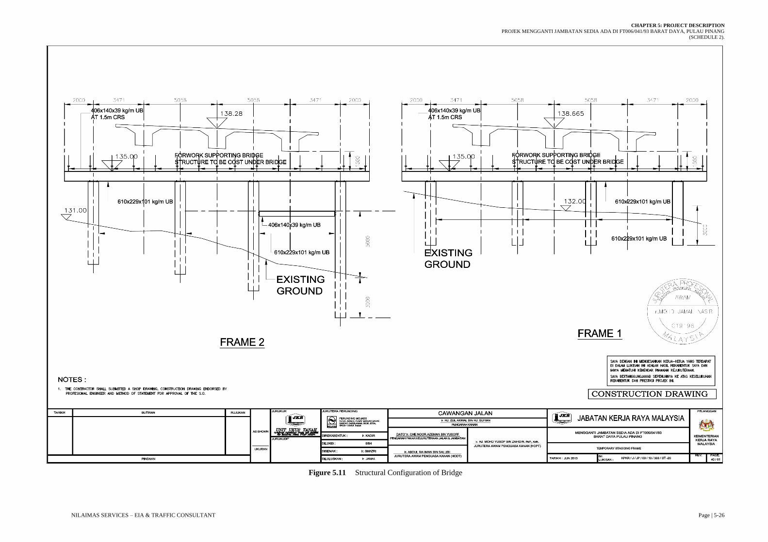
working load for 1.5m diameter micropile is 1000 kN. Bridge over Sg. Pinang consist of 6
general staging of beam with the structural configuration of 2.0m + 3.47m + 5.058m + 5.058m +
3.471m + 2.0m. The detail of the drawing as in Figure 5.11.

CHAPTER 5: PROJECT DESCRIPTION
PROJEK MENGGANTI JAMBATAN SEDIA ADA DI FT006/041/93 BARAT DAYA, PULAU PINANG (SCHEDULE 2).
NILAIMAS SERVICES – EIA & TRAFFIC CONSULTANT Page | 5-24
Figure 5.9 Micropile Specification for Project Titi Kerawang

CHAPTER 5: PROJECT DESCRIPTION
PROJEK MENGGANTI JAMBATAN SEDIA ADA DI FT006/041/93 BARAT DAYA, PULAU PINANG (SCHEDULE 2).
NILAIMAS SERVICES – EIA & TRAFFIC CONSULTANT Page | 5-25
Figure 5.10 Column Specification for Project Titi Kerawang
CHAPTER 5: PROJECT DESCRIPTION
PROJEK MENGGANTI JAMBATAN SEDIA ADA DI FT006/041/93 BARAT DAYA, PULAU PINANG (SCHEDULE 2).
NILAIMAS SERVICES – EIA & TRAFFIC CONSULTANT Page | 5-26
Figure 5.11 Structural Configuration of Bridge

CHAPTER 5: PROJECT DESCRIPTION
PROJEK MENGGANTI JAMBATAN SEDIA ADA DI FT006/041/93 BARAT DAYA, PULAU PINANG (SCHEDULE 2).
NILAIMAS SERVICES – EIA & TRAFFIC CONSULTANT Page | 5-27
Design Specification
The detailed design shall be carried out in accordance with the following Codes of Practice and
Specifications (Table 5.4):-
Table 5.4 British Standards, UK DOT Technical Memoranda and other standards
ARAHAN TEKNIK (JALAN) 8/86 GEOMETRIC DESIGN OF ROADS
BS 5400 Part 1 (1988) General Statement
BS 5400 Part 4 (1990) Code of Practice for the design of concrete bridges
BS 5400 Part 7 Specification for materials and workmanship, concrete,
reinforcement and prestressing tendons.
BS 5400 Part 8 Recommendations for materials and workmanship, concrete,
reinforcement and prestressing tendons
BS 5400 Part 9.1 Code of Practice for the design of bearings. Specification for
materials, manufacture and installation of bridge bearings.
BS 5400 Part 10 Code of Practice for fatigue
BS 6779 Parapets for vehicle containment on highways
BS 8004 Foundations
BS 4466 Scheduling of Reinforcement (To be prepared by successful
Contractor)
BS 5896 or ASTM A416/ASTM
A416M-98 Prestressing Strand Specification
BD 24/92 Design of concrete bridges – Use of BS 5400 Part 4
BD 28/87 Early Thermal Cracking of Concrete (+Amendment No. 1)
BD 37/01 Loads for highway bridges
BD 52/93 Design of concrete bridges – Use of BS 5400 Part 4
BD 33/94 Expansion Joints for Use in Highway Bridge Decks
BA 57/01 Design for Durability

CHAPTER 5: PROJECT DESCRIPTION
PROJEK MENGGANTI JAMBATAN SEDIA ADA DI FT006/041/93 BARAT DAYA, PULAU PINANG (SCHEDULE 2).
NILAIMAS SERVICES – EIA & TRAFFIC CONSULTANT Page | 5-28
Pavement Design
Manual for Structural Design of Flexible Pavement, ATJ 5/85 (Pindaan 2013) is used for the
pavement design analysis.
5.5.2 Available Traffic Information
Road Traffic Volume Malaysia RTVM (2018) is preferable to get the required information on
Average Daily Traffic (ADT) for the design Equivalent Standard Axle Load (ESAL). Based on
the available census station map (Figure 5.12), the closest stations relative to the site location is
outlined along with the respective Average Daily Traffic Volume (Table 5.5). The study has
been conducted by Highway Planning Unit (HPU), under Ministry of Works Malaysia by using
Type 3 survey which indicated that 16 hours survey for one (1) day from 0600 till 2200.
Table 5.5 Referable Census Station for Analysis Consideration
CENSUS NO. ROUTE DESCRIPTION OF LOCATION TYPE OF
CARRIAGEWAY
PR205 FT006 Georgetown – Telok Bahang – Balik
Pulau (Jalan Keliling Pulau) T1-1
Based on the census map from Road Traffic Volume Malaysia (RTVM) 2018, PR205 is the
closest and can be the representative reference station for the traffic forecast in term of trip
origin-destination route for Balik Pulau and Teluk Bahang. In general, for the year 2018, the
observed traffic growth rate for Pulau Pinang is 1.69%. In fact, the 16-hour traffic volume
displayed an increase of 2.40% from the year 2017 to 2018. The volume capacity stated above
also included the road users from the growth centre of Balik Pulau which is 4km away from the
project site. These numbers are not specifically representing the number of road users passing
through the existing bridge of Jambatan Titi Kerawang.
Traffic Impact Assessment (TIA) were carried out and the road capacity analysis were
determined to be at LoS A for both AM and PM peak hours with volume capacity ratio of 0.17
and 0.23 respectively. During construction, LoS will degrade to F due to closure of one (1) lane.
Modelling results indicated a queue length of 1 km with a delay time of 359 seconds. The
complete traffic study for this project site is fully discussed in Appendix 7-B.

CHAPTER 5: PROJECT DESCRIPTION
PROJEK MENGGANTI JAMBATAN SEDIA ADA DI FT006/041/93 BARAT DAYA, PULAU PINANG (SCHEDULE 2).
NILAIMAS SERVICES – EIA & TRAFFIC CONSULTANT Page | 5-29
(Source: Road Traffic Volume Malaysia 2018, HPU)
Figure 5.12 Project Location on Census Map for Penang
Project Site
CHAPTER 5: PROJECT DESCRIPTION
PROJEK MENGGANTI JAMBATAN SEDIA ADA DI FT006/041/93 BARAT DAYA, PULAU PINANG (SCHEDULE 2).
NILAIMAS SERVICES – EIA & TRAFFIC CONSULTANT Page | 5-30
Design Procedure Based on ATJ (Jalan) 8/86
The selection of the required design standard should begin with the assessment of the function of
the proposed road and the area it traverses. The location of a road and its design are considerably
influenced by the topography, physical features, and land use. Geometric design elements such
as alignment, gradients, sight distance and crossection are directly affected by topography and
must be selected so that the road designed will reasonably fit into those natural and man-made
features and economise on construction and maintenance. The general geometric design of the
road and bridge is discussed below:
Geometric Design Information
Speed is the primary factor in all modes of transportation and is an important factor in the
geometric design of roads. The speed of vehicles on a road depends, in addition to capabilities of
the drivers and their vehicles, upon general conditions such as physical characteristics roadway,
the weather, the presence of other vehicles and the legal speed limitations.
The speed is selected to meet the needs of the road to fulfils its function. Thus, roads which are
planned to provide long-distance travel will be designed with a higher speed while those which
provides short distance travel can be given a lower speed.
The operating speed is the highest overall speed at which a driver, can travel on a given road
under favourable weather conditions and under prevailing traffic conditions without at any time
exceeding the design speed.
Design speed is the maximum safe speed that can be maintained over a specified section of the
road when conditions are so favourable that the design features of the road govern. The assumed
design speed of this project is 50 km/hr with respect to the topography, the adjacent land use and
the type of road. The consideration to use as a design speed of such as practicable while
maintaining the desired degree of safety, mobile and efficiency. Table 5.6 indicates the selection
of design speeds to rural and urban standards.

CHAPTER 5: PROJECT DESCRIPTION
PROJEK MENGGANTI JAMBATAN SEDIA ADA DI FT006/041/93 BARAT DAYA, PULAU PINANG (SCHEDULE 2).
NILAIMAS SERVICES – EIA & TRAFFIC CONSULTANT Page | 5-31
Table 5.6 Design Speed of Road
DESIGN
STANDARD
DESIGN SPEED (km/hr)
TERRAIN
FLAT ROLLING MOUNTAINOUS
R6 120 100 80
R5 100 80 60
R4 90 70 60
R3 70 60 50
R2 60 50 40
R1 40 30 20
R1a 40 30 20
Minimum Radius
The minimum radius is a limiting value of curvature for a given speed arid is determined from
the maximum rate of superelevation and the maximum allowable side friction factor. Flatter
curves should always be wherever possible. There is no necessity to provide any transition
(spiral) curves. The minimum radius to be used for the designated design speed and maximum
superelevation rates as tabulated in Table 5.7.
Table 5.7 Minimum Radius for Road Design
DESIGN SPEED (km/hr) MINIMUM RADIUS
e = 0.06 e = 0.10
20 15 15
30 35 30
40 60 50
50 100 85
60 150 125
80 280 230
100 465 375
120 710 570

CHAPTER 5: PROJECT DESCRIPTION
PROJEK MENGGANTI JAMBATAN SEDIA ADA DI FT006/041/93 BARAT DAYA, PULAU PINANG (SCHEDULE 2).
NILAIMAS SERVICES – EIA & TRAFFIC CONSULTANT Page | 5-32
Road Standards
The design standard is classified into seven groups (R6, R5, R4, R3, R2, R1 & R1a) for rural
areas and into seven groups (U6, U5, U4, U3, U2, U1 & U1a) for urban areas. These are in
descending order of hierarchy.
Roads which function to provide long-distance travel will require higher, design speeds whilst
road which serve local traffic, where the effect of speed is less significant can have a lower
design speed. Also, roads with heavier traffic will be provided with a higher standard. For this
project, it is subjected to both R5 and R3 Design Specifications.
a. Standard R5/U5:
Provides also high geometric standard and usually serve long to intermediate trip lengths
with high to median travelling speeds. It is usually with partial access control, The Highway,
Primary Road and Arterial fall under this standard.
b. Standard R3/U3
Provides low geometric standard and serves mainly local traffic. There is partial or no access
control. The Secondary Road, Collector or Major Local Streets falls under this standard.
Design Vehicles and Characteristics
The physical characteristics of vehicles and the proportions of various size vehicles using the
roads affect the geometric design of roads. A design vehicle is a selected motor vehicle the
weight, dimensions and operating characteristics of which are used to establish highway design
controls to accommodate vehicles of a designated type. For purposes of geometric design, the
design vehicle should be one with dimensions and minimum turning radius larger than those of
almost all vehicles in its class.
Since the proposed bridge and road project is designed for future traffic the sizes of vehicles used
in the design should be determined by analysing the trends in vehicle dimensions and
characteristics. The design vehicles to be used for geometric design follows that used by
AASHTO as in Chapter II of AASHTO “Design Vehicles” – A Policy of Geometric Design of
CHAPTER 5: PROJECT DESCRIPTION
PROJEK MENGGANTI JAMBATAN SEDIA ADA DI FT006/041/93 BARAT DAYA, PULAU PINANG (SCHEDULE 2).
NILAIMAS SERVICES – EIA & TRAFFIC CONSULTANT Page | 5-33
Highway and Streets (1984). Figure 5.13, Figure 5.14 and Figure 5.15 shows the dimension
and turning characteristics for the P, SU and WB-50 design vehicles. Table 5.8 summarizes the
design vehicle dimensions and characteristics.
(Source: AASHTO – Geometric Design of Highway and Street (1984) Figure 11-1)
Figure 5.13 The dimension and turning characteristics for the design vehicles (P)
CHAPTER 5: PROJECT DESCRIPTION
PROJEK MENGGANTI JAMBATAN SEDIA ADA DI FT006/041/93 BARAT DAYA, PULAU PINANG (SCHEDULE 2).
NILAIMAS SERVICES – EIA & TRAFFIC CONSULTANT Page | 5-34
(Source: AASHTO – Geometric Design of Highway and Street (1984) Figure 11-2)
Figure 5.14 The dimension and turning characteristics for the design vehicles (SU)
(Source: AASHTO – Geometric Design of Highway and Street (1984) Figure 11-3)
Figure 5.15 The dimension and turning characteristics for the design vehicles (WB-50)

CHAPTER 5: PROJECT DESCRIPTION
PROJEK MENGGANTI JAMBATAN SEDIA ADA DI FT006/041/93 BARAT DAYA, PULAU PINANG (SCHEDULE 2).
NILAIMAS SERVICES – EIA & TRAFFIC CONSULTANT Page | 5-35
Table 5.8 Design Vehicle Dimension
DESIGN VEHICLE DIMENSION IN METER TURNING
RADIUS
(m) Type Symbol Wheel
Base
Overall Overall
Length
Overall
Width Height
Front Rear
Passenger
Car P 3.4 0.9 1.5 5.8 2.1 1.3 7.3
Single Unit
Truck SU 6.1 1.2 1.8 9.1 2.6 4.1 12.8
Truck
Combination WB-50 7.9 0.9 0.6 16.7 2.6 4.1 13.7
The vertical profile of the road affects the performance of vehicles. The effects of grades on
trucks which have weight power ration of about 300 lb/hp are considered. The maximum grade
controls in terms of design speed are summarized in Table 5.9.
Table 5.9 Maximum Grades
DESIGN SPEED (km/hr) DESIRABLE MAXIMUM
GRADE (%) MAXIMUM GRADE (%)
120 2 5
100 3 6
80 4 7
60 5 8
50 6 9
40 7 10
30 8 12
20 9 15
Road Standard R1a 10 25
The desirable maximum should be aimed at in most cases. The maximum grades should be used
infrequently. The total upgrade for any section of road should not exceed 3000m unless the grade
is less than 4%. Where a particular section is made up of a combination of upgrades, the length
of the critical grade should take into consideration, the entire section of the combination. A speed

CHAPTER 5: PROJECT DESCRIPTION
PROJEK MENGGANTI JAMBATAN SEDIA ADA DI FT006/041/93 BARAT DAYA, PULAU PINANG (SCHEDULE 2).
NILAIMAS SERVICES – EIA & TRAFFIC CONSULTANT Page | 5-36
reduction/recovery curve should be plotted to determine the critical grade length base. The
critical grade lengths for the various speeds are as shown in Table 5.10.
Table 5.10 The Critical Grade Length for Various Speeds
DESIGN SPEED GRADIENT (%) CRITICAL GRADE
LENGTH (m)
120
3
4
5
500
400
300
100
4
5
6
500
400
300
80
5
6
7
500
400
300
60
6
7
8
300
250
200
50
7
8
9
250
170
150
40
8
9
10
200
170
150
30 - Not defined - decision left to
the designer
20 - Not defined - decision left to
the designer
5.6 INFRASTRUCTURE AND UTILITIES
All infrastructure and utilities for the Project shall be made available prior to a new operation of
the proposed project. Some of the requirement will be installed when space is available. Details
of these requirements are described as follows;

CHAPTER 5: PROJECT DESCRIPTION
PROJEK MENGGANTI JAMBATAN SEDIA ADA DI FT006/041/93 BARAT DAYA, PULAU PINANG (SCHEDULE 2).
NILAIMAS SERVICES – EIA & TRAFFIC CONSULTANT Page | 5-37
5.6.1 Infrastructure
Drainage System
The proposed drainage along the stretch will also need to be constructed to allow runoff at the
Project site to direct flow toward the proposed sedimentation units (mobile silt trap). The silt trap
will discharge into outflow drainage before entering nearby streams. The drainage system will be
built during the pre-development stage and progressively installed with permanent features.
Sewage
Sewage is mostly originating from portable toilets on-site. Discharge of sewage system is very
limited for a project site with a small number of workers. It shall be disposed by the appointed
contractor and to be treated to meet Environmental Quality (Sewerage) Regulation 2009.
Solid Wastes
Solid wastes are not expected to become any problem in the operation. It is just in term of solid
wastes from machinery such as used parts which shall be collected and recycled wherever
possible. Vegetation wastes will be decomposed on the designated dumping area away from the
project site. The amount is little as the area involved is small and also to be developed in stages.
Domestic wastes are basically generated garbage from workers resting areas. The quantity is
minimal and shall be internally collected and disposed of. No open burning is allowed.
Scheduled Wastes
Scheduled wastes expected to be generated from the Project site are used engine oil (SW304,
SW305), fuel and grease. Spillages of liquids such as lubricating oils, diesel and hydraulic fluids
are likely to affect surface water quality if they enter surrounding water bodies. Provided that any
hazardous wastes generated from the development are stored, transported and disposed of in
accordance with regulations and appropriate measures, then associated impacts shall be minor.
Electricity Supply
The estimated load for domestic use for on-site usage is very minimal. Electricity power supply
for the project site will be tapped from nearby existing Tenaga Nasional Berhad substation if

CHAPTER 5: PROJECT DESCRIPTION
PROJEK MENGGANTI JAMBATAN SEDIA ADA DI FT006/041/93 BARAT DAYA, PULAU PINANG (SCHEDULE 2).
NILAIMAS SERVICES – EIA & TRAFFIC CONSULTANT Page | 5-38
available. However, most of the time, the electrical supply shall be coming from the generator set
stationed on-site for ad-hoc and temporary usage.
Telecommunication
The telecommunication network is required for communication of personnel at site and the
outsiders. Such facilities shall be made available such as cellular phone shall be provided for
respective Project personnel and cable line for administration buildings/office.
5.7 PROJECT IMPLEMENTATION SCHEDULE
The details of the development program of the project have yet to be finalized. According to the
conceptual plan for the proposed project, the construction of the road will be developed in one
(1) phase only. As soon as all the necessary approvals (including that of EIA Report) are
obtained, the proponent plans to launch the project and possibly starts the activities immediately.
Project implementation consists of carrying out the activities with the aim of delivering the
outputs and monitoring progress compared to the work plan. Monitoring can be defined as
control of the project implementation in order to keep the project on track and achieve the end
results of the project. The project manager is responsible for the regular monitoring of the
project, but the partner organizations should also contribute actively to the effective monitoring
of the project. The whole partnership will benefit from monitoring of project progress because of
it:
Provides support for project implementation and acts as an indicator of whether targets are
being met;
Through feedback activities, it stimulates improvement in project results based upon
observations of the value and the quality of the various elements of the project;
Provides reliability and credibility of results; and
Foresees potential problems in good time and simplifies decision-making, especially if
corrective actions are necessary.

CHAPTER 5: PROJECT DESCRIPTION
PROJEK MENGGANTI JAMBATAN SEDIA ADA DI FT006/041/93 BARAT DAYA, PULAU PINANG (SCHEDULE 2).
NILAIMAS SERVICES – EIA & TRAFFIC CONSULTANT Page | 5-39
In order to ensure all the best environmental management practices and procedures to be
implemented during the project progress, the appropriate organizational structure is necessary to
ensure successful implementation during the development and operation phase. Every project
team member holds their own responsibilities. Roles and general responsibility of project team
members are as tabulated in Table 5.11 below:
Table 5.11 Roles and General Responsibility of the Project Team
ORGANIZATION ROLES GENERAL RESPONSIBILITY
Jabatan Kerja Raya
(JKR) Barat Daya
Client / Project
Proponent
To adheres to all environmental regulations and
acts;
To incorporate an environmental requirement in
the contractual documentation to ensure its
implementation;
To communicate environmental requirements to
the other project team members to ensure
compliance;
To monitor compliance with the environmental
requirements by all parties involved in the
project;
To relook safety and environmental matters.
Nilaimas Services Environmental
Consultant
Conduct a study for the preparation of EIA
To assist and advise project proponent in the
implementation of the EIA
Monitor implementation of EIA, EIA approval
conditions and compliance with other relevant
environmental requirements (Environmental
protection works);
Assisting in the resolution of conflicts
Communicate all modification of the EIA to the
relevant stakeholders
5.8 PROJECT IMPLEMENTATION SCHEDULE
Before any activity could proceed, the Project Proponent will submit an Environmental Impact
Assessment (EIA) Report to the Department of Environment (DOE) for approval. The

CHAPTER 5: PROJECT DESCRIPTION
PROJEK MENGGANTI JAMBATAN SEDIA ADA DI FT006/041/93 BARAT DAYA, PULAU PINANG (SCHEDULE 2).
NILAIMAS SERVICES – EIA & TRAFFIC CONSULTANT Page | 5-40
implementation of the project includes all aspects of planning, procurement, construction and
commissioning of the project. The schedule of construction work is shown in Appendix 5-F.
5.9 PROJECT ABANDONMENT
Abandonment can occur at any stage of the Project. Abandonment during the planning stage will
probably not require any follow-up activities. Abandonment during the construction or the
operational stage requires the Project Proponent to consider plans for the removal or disposal of
temporary structures and facilities. In addition, restoration plans and works for the Project area
after the cessation of the Project will have to be undertaken.
Abandonment of the project means that the entire project or a part of the project should be
cancelled for reasons that cannot be avoided. Therefore, steps should be taken to prepare in the
event of cancellation and failure of the project.
The main contractor and the consultant appointed shall comply with all the terms and conditions
outlined in the EIA report for the project, taking into account all the conditions imposed. In the
event of problems during construction or project proponent that is the main contractor fails to
complete the project well, the agencies will take an action which aimed at solving the problems
with the project proponent. The implementing agencies have to resolve issues arising in
connection or appoint another consultant to complete the project.
The main contractor is responsible for completing re-emerging issues that led to the cancellation
of the project and propose measures necessary repairs to maintain the quality of the environment.
Therefore, some measures must be implemented as follows:
i. All the areas were cleared for development purposes must be redeemed by way of
rehabilitation or conservation approved by the authorities, including comprehensive
replanting in cleared areas. The exposed area, especially the middle developed areas
should be preserved and protected from outside interference, which has no other purpose.
ii. All wastes generated and the balance remains to be covered and protected from the
weather to prevent runoff that causes erosion and leaching of pollutants.

CHAPTER 5: PROJECT DESCRIPTION
PROJEK MENGGANTI JAMBATAN SEDIA ADA DI FT006/041/93 BARAT DAYA, PULAU PINANG (SCHEDULE 2).
NILAIMAS SERVICES – EIA & TRAFFIC CONSULTANT Page | 5-41
iii. Measures for environmental protection should be implemented to control erosion,
landslides, water pollution and the destruction of biomass and also reduce negative
effects either for long term or short term.
iv. Rivers and drainage system must be maintained while maintaining the shape and pattern
of the existing flow.
v. All the building materials were not used in the project area can be removed by the
proposed method as shown below:
Reuse
Materials that cannot be recycled should be disposed of in an approved landfill only.
The equipment and machinery used for construction left at the construction site had to
be taken to the storage area.