
CHIP FORMATION AND CHIP BREAKING PROCESSES IN ...
236
CHIP FORMATION AND CHIP BREAKING PROCESSES IN METAL CUTTING A thesis submitted to the University of Sheffield for the decree of Doctor of philosophy ISHAIL HASSAN MAGHDI ALMA.NDILA\'/I (M.Sc'. Eng., Leningrad, U.S.S.R.) in the Department of mechanical Engineering The University of Sheffield March 1971
-
Upload
khangminh22 -
Category
Documents
-
view
1 -
download
0
Transcript of CHIP FORMATION AND CHIP BREAKING PROCESSES IN ...

CHIP FORMATION AND CHIP BREAKING
PROCESSES IN METAL CUTTING
A thesis submitted to the University of Sheffield for
the decree of Doctor of philosophy
ISHAIL HASSAN MAGHDI ALMA.NDILA\'/I
(M.Sc'. Eng., Leningrad, U.S.S.R.)
in the
Department of mechanical Engineering
The University of Sheffield
March 1971

TO MY BROTHER
Dr. SADIQ HASSAN M. ALMANDlLAWI. M.D.

CONTENTS
ACKNO\iLEDGEHENT
SUHHARY
CHAPTER
1.1
1.2
1.3
1.3.1
1.3.2
1.3.3
1.4
1.5
1.6
1.7
1.8
1 A Discussion of Metal Cutting Studies
Hachinability
Chip Formation
Types of Deformed Chips
Discontinuous
Continuous without Built-up Edge
Continuous with Built-up Edge
Discontinuous Chip Formation
General Remarks on the Parameters
Influencin~ Chip Formation Process
Influence of Rake Ansle on the Chip
Formation Process
Influence of a Built-up Edge on Chip
Formation Process
Influence of Friction on Chip Formation
Process
Idealisation of Materials
Derrivation of Strain for Single Slip-line
Strain for a Pair of Slip-lines
1.9 Strain Rate in Fan Region, Series Expression
for Curvature and Numerical Integration for
a Particular Example
1.10
1.11
1.12
1.13
Measure of Strain
Shape of Strained Circle
Direction of Texture
Plotting Deformed Shape
Page
i
ii
1
1
5
9
9
9
10
11
19
20
21
23
25
26
30
32
35
36

CHAPTER 2
2.1
2.2
2.2.1
2.2.2
2.2.3
2.3
2.4
2.5
2.6
2.7
2.8
2.9
2.9.1
2.9.2
2.9.3
2.10
2.10.1
2.10.2
2.10.3
2.10.4
2.10.5
2.11
2.12
Cl1APTER 3
3.1
Dynamometry
General Introduction
Types of Neasurine Instruments
Absorption Dynamometers
Transmission Dynamometers
Force Measuring Instruments
Dial Gauge Dynamometers
Hydraulic Devioes
Pneumatic Devices
Optical Devices
Piezoelectric Crystals
Electrioal Devices
Design of Tool Dynamometer
Design, Heat-Treatment and Dimensions
of the Hain Parts of the Tool Dynamometer
Adjustment of the Dynamometer
Calibration of the Tool Dynamometer
Strain Gauge Dynamometer
Circuit Design
Dynamometer Cantilever
Determination of Several Parameters
Choioe of Galvanometer
Maximum Trac~ Deflection
Instrumentation
Calibration of the Strain Gauge Dynamometer
Chip Breaking
3.2 Cutting Operations from Chip Breaking Point
of View
Page
38
38
39
39
40
40
41
44
44
45
46
46
47
48
53
53
5lt-
55
56
56
58
59
59
60
61
61
3.2.1
3.2.2
3.2.3
3.2.4
3.2.5
3.3
3.4
3.5
3.6
3.7
3.8
3.9
Turning and Boring
Drilling
Milling
Broaching
Tapping and Reaming
Why Use Chipbreakers?
Types of Chipbreakers
Chipbreaker Geometry
Breaking of the Chip
General Views of the Chip Breaking Methods
Effect of Coolant on Chip Breaking
The Effect of Grinding on Chip Breaking
3.10 Chip Breaking by means of Interrupted Feed
Devices and Vibratory Methods
3.11 Chip Curl Radius
3.12 Chip Breaking Effectiveness
CHAPTER 4
4.1 Analysis of the Experimental Results
4.1.1 General Analysis of the Experimental
Results
4.1.2 Summary of some o£ the Experimental
Results
4.2 Deductions from the Analysis of the
Zxperimental Results
4.2.1 Deductions from the Analysis of the
Rxperimental Results obtained at Law
Cutting Speeds
Deductions from the Analysis of the
Experimental Results obtained at High
Cutting Speeds
Page
62
62
63
63
63
64
65
67
68
70
78
78
79
81
92
96
96
96
105
107
107
109

CHAPTER 5
5.1
5.2
5.3
CHAPTER 6
Conclusions
APPENDIX I
APPENDIX II
General Deductions from the Experimental
Results
General Discussion
Discussion of the Experimenta1 Results
Recomendations for Future Work on Chip
Breaking
Theoretical Analysis of Chip Curling
Mechanism for both Clamped Wedge and
Ground Step Chipbreakers
Forces Ac:ting on the Chipbreaker
BIBLIOGRAPHY
Page
111
113
113
116
119
120
120
122
127
129

ACKNO'tlLEDG EI1 ENTS
The author would like to express his gratitude to his
father,HAJ HASSAN HAGHDI ALMANDILAWI. whose financial support
made this research possible. Special thanks are due to Prof
essor D.S.Dugdale for his supervision and guidance throughout
this work. He also wishes to thank the firm of Firth Brown
Tools Limited, for supplying tools and materials.
Finally the auther is indebted to Hr. J. D. Trott and
staff in the machine shop and photoeraphy section for their
assistance.
I. H. M. A.
'j

- ii -
Smn-lARY
This investigation has been carried out to analyse and
discuss the chip formation and chip breaking processes in metal
cutting and to demonstrate the degree of agreement between the
theoretical and experimental results. Particular attention has
been given to the chip breaking control.
Different materials such as steels (low, medium and high
carbon steels), aluminium alloy and copper were tested under
different cutting conditions using different tool geometries
wi th ground and clamped chipbreakers, and cutting ''las carried
out dry and with coolant. The chips obtained were measured, and
the experimental results were plotted.
For the chips to be controlled at the cutting zone and
effectively transported from the vicinity of the machine tool,
it is essential chipbreakers are used.
Chip breaking effectiveness was found to be influenced
chiefly by the ratio of chip curl radius to feed. The condition
for minimum cutting force was found to be influenced chiefly by
the chipbreaker proportion ratio, i.e. the width/height for
ground step chipbreaker and width/angle of the inclination of the
chipbreaker wed~e for clamped wedce chipbreaker. Chipbreaker
proportions are limited on the one hand by the need to get suff
iciently broken chips and on the other hand by the need to avoid
extensive increase in cut tine forces, which should not increase
by more than about 10 %.
During this work it was established that the use of chip
breaker having optimum dimensions will not only eive broken chips
with reduced cuttin~ force , but also that there will be no increase
in tool wear due to the presence of a chipbreaker. Coolant was

- iii -
found to be helpful in promoting good chip breaking performance.
Charts were drawn for quickly findine chipbreaker dimen
sions for effective chip breaking over a wide ranee of cutting
conditions and materials. A theoretical expression for chip breaking
effectiveness in terms of chip cnrl radius and chipbreaker
proportions was suggested.
I. H. M. A.

- 1 -
CHAPTER 1
A DISCUSSION OF METAL CUTTING STUDIES
1.1 l-~ACHINABILITY
Although the term "machinability" is widely used, and from the
practical point of view is readily understood as denoting a relative
quality, there is no general agreement on a precise definition.
Good machinability may carry implications concerning,
(1) Low energy absorbed in cutting.
(2) Long tool life.
(3) Good surface finish.
(4) Formation of chips that can be easily disposed of.
The main factors(1,2) related to machinability are:
(1) Workpiece Material:
grain sizer chemical composition; melting and casting
processes; method of fabrication, e~g. cast, forged,
drawn or rolled; type of heat-treatment, e.g. annealed,
hardened by quenching, tempered or aged; microstructure;
distribution, type and characteristics of icluded non
metals; properties: tensile strength, ductility and
hardness; size and shape.,
(2) Cutting Tool:
e.g. form, shape, angles; heat-treatment; hardness and
strength; alloy composition; accuracy of grinding.
(3) Machine Tool:
machine type; rigidity of tools and work-holding devices;
specification of the operation.
(4) Cutting Conditions:
cutting speed; feed; depth of cut

- 2 -
(5) Cutting Fluid:
type: soluble water ,. mineral, lard, solfurized oil etc.;
cooling properties.
Materials having good machinability permit a high rate of
metal removal with satisfactory tool life and surface finish.
Machinability assessments have been mainly based on consider-
ations of tool wear, the chip behaviour and the energy consumption in
machining.
By considering in the first instance, only one criterion
of machinability such as surface finish, Rubenstein(3) considered
machinability of a material as a quality that changed in an adverse
way with increasing ductility, under the conditions existing during
cutting. An index of ductility is shown to be a valid index of
machinability as assessed by surface finish, by cutting force magnitude,
or by tool wear within a limited set of cutting conditions. Meta-
llurgica1 investigations into the causes of wear of cemented carbide
tools have been carried out by Trent(4) to provide some evidence of
the conditions at the cutting edge of the tool and the factors
controlling tool life and machinability.
Tool life under machine shop conditions is known to be the
result of a number of different processes and factors which affect
tool life in different ways and subject to different laws. Flank wear,
the built-up edge (Fig.1a-e)(~) t deformation of the tool subjected
to high temperatures and stresses, cratering wear, mechanical chipping,
and thermal cracking all affect the' useful length of tool 1ife(4).
Cratering we~r is a form of wear on rake (cutting) face of the
tool occurring at rela.tive1y high cutting speeds. This form of wear is
consequently very temperature sensitive •. Oxley and We1sh(5) suggested
that the value of the ratio of m/k to~ether with the value of k
(where m is the slope of stress-strain curve at mean strain rate
and k is the shear flow stress), which are fund~menta1 material

e F,G 1

- 3 -
properties, should be taken as an indication of the way in which
a material machines. Materials having high values of m/k and k
are expected to machine with large cutting forces, thick chips
and result in poor surface finish.
The shear angle(6) has been used as a factor in estimating
machinability. High values of shear angle indicate large ranges of
continuous chips, low cutting forces and good surface finishes.
Low shear angles are associated with small ranges of continuous
chips, large cutting forces and poor surface finishes.
A basic factor in machinability is the stress required to
shear the work material at high temperature and extremely high strain
rate. This may explain the poor machinability of materials of high
creep strength.
Trent(?) concluded that metallurgical behaviour of the work
material in extreme conditions of the flow zone, is probably the
most important factor in machinability. Improvements in the mach-
inability characteristics of steel can be made by means of inclusions
such as MnS which can act as internal lubricants, forming films on
the cutting face of the tool which are easily sheared under these knS extreme conditions or silicates which can also act as lubricants
greatly reducing stresses, temperatures, and tool wear.
The examination of worn tOOls(?) lead to the conclusion
that the main wear process on carbide tools are based on diffusion
wear and attrition. Diffusion wear is mainly controlled by temperature,
the flow rate of the work material very close to the tool surface,
and the diffusion relations between tool and work material. Attrition
is dependent mainly on irregularity in flow of material over the
tool surface and is therefore greater at low speed. Neither diffusion
nor attrition wear depends on high hardness of the work material
(Fig.2 )(7). a-c
Experiments on lubrication of tools show that gases can

a b
c
e f
F,G. 2

_ l~ _
penetrate to some distance between tool and work from edges of the
area of contact at medium and low cutting speeds. The freshly
generated metal surfaces act as an absorbent for atmospheric oxygen
and protect the tool when cutting in air from a form of wear which
may be very rapid when a jet of oxygen or water is directed at the
tool (Fig.2d
_f}(7).
Experiments on aluminium alloys(8) have shown that pure
aluminium tends to weld at the tool cutting face. This tendency is
reduced as the tensile properties of the aluminium are increased
by alloying, heat-treatment or cold working. Built-up edge could
be avoided by maintaining a keen cutting edge, polishing the tool
surface over which the chips flow, allowing adequate rake and
clearance angles, and providing a suitable lubricant.
Electrochemical machining (ECM) is one of the newest methods
of metal removal for mass production and offers new possibilities
for improving machinability. There is no problem of tool wear in
ECM.
Mechanical abrasion of the tool material, micro-crumbling
due to cold welding of tool material and workpiece material,
diffusion between tool and workpiece materials, weakening of tool
material with consequent plastic deformation, and fracture due to
mechanical stress are the most effective causes of tool wear(9).
One of the most successful criteria of machinability is
the permissible cutting speed.
where:
According to Kronenberg's law of cutting speed:
1
V60 = Cv/AlV
V60 is the permissible speed- the average speed of a tool
in work for 60 mins.,
Cv
and ~ are material constants,
A is area of cut.

- 5 -
For geometrically similar sections of cut the depth feed ratio C
is constant
c = t / s
where:
t is depth of cut
S is feed
and the area of cut is:
2 A = t S = C S
Hence equation (1.1) reads:
1 -€ = c / (CS2 ) v v
1.2 CHIP FORMATION
Recently, theoretical studies on metal cutting have been
well developed, especially regarding the fundamental analysis of
the mechanics of orthogonal cutting in which a continuous or
discontinuous chip is produced. Various theories have been presented
by Time(10), zvorykin(11), Briks(12), Piispanen"(1 3), Ernst and
Merchant(14), Field and Merchant(15), Cook, Shaw and Finnie(16),
Zorev(17), Lee and Shaffer(18) t Hill(19) and several others
assuming a perfectly plastic solid without strain hardening or
inhomogenity of the material. In most analysis, however, it has
also been assumed for the sake of simplicity, that the chip formation
is a process of shear (without fracture for the continuous chip and
with fracture for discontinuous chip) confined to a single plane
extending from the tip of the cutting tool to the sharp intersection
of free surface of workpiece and chip, i.e. the shear plane. All
these theories were based on the single plane concept.
(20) (21) . (22) Okushima and Hitomi ,Nakayama t Okushl.ma t
(23) d P 1 (24) h Keceaoglu • and Christopherson, Oxley an a mer ave
analysed the cutting mechanism and concluded that there is a family
of shear planes within the deformation zone. Okushima(22) showed,

- 6 -
experimentally by photomicrographs, that the shear process took,place
over a large area instead of along a single plane.
The chip formation process during orthogonal cutting can be
Looked upon as a case of plane atrain deformation if the width of the
layer of metal being removed is considerably greater than its' thickness.
This method of chip formation was- first suggested by'Time(10) and a
d 1 t 'd t b Z k' (11) further eve opmen was carr1e ou y vary 1n • According to this
method the shear deformations during the transformation of the layer
into a chi~ occur along a certain unique plane~
Deformation methods based on the single shear plane were justly
criticized by Briks(12). Briks suggested that the plastic shear in
the working surface occurs in a family of fan wise arranged planes which
pass through the cutting edge 0 (planes 0 Ao' 0 A1 •••••••• 0 An)'
Fig. 3. The outer surfaces of the work and the chip are separated by a
certain transition surface Ao An. This scheme' of deformation has several
drawbacks. Firstly, assuming that the transition 5Urface intersects; the
outer surface of the chip so that the transition surface tangent at the
pOint An forms a certain angle! (which is about half the cutting angle).
with the outer surface of the chip. The particles of the machined
material. thus.; receive infinitely great accelerations as-, they pass
through the plJane 0 A. Secondly. Briks considered the shear lines'to n
be straight. As it follows from the boundary conditions on the transition
--surface that all the shear lines must form equal angles ofJ1/4 with
the tangents to this surface. the shear lines therefore. must be
curved. Fig., 4. For example, the straight shear line OA1
forms· an
angle fi <J/;4 wi th the tangent X1• In actual fact this. angle must be
J'l/4 in which case the shear line must be curved as: shown in Fig. 3 by
at dotted line. Since stresses C)x1 and 6Y1 at point A1 are principal
because there are no external loads on the transition aurface AoAn' th&
lines of maximum tangential stress at point A1 thus forms an angle


- ? -
'Z = .17/4 with tangent X1-
On the assumption that there is no, friction on the contact
surfaces, IlyuShin(25) suggested that within the deformation zone Mt
Fig. 4, there are two families of mutually orthogonal curves with s ~
constant ang1e.// /2 between the tangents to a pair of neighbouring
curves of one family as: the~ move along these lines. The normal to
the transition curve and the tangent to the. shear line at the point
of intersection, form an angle ofJ'lj4. This is so, due to the fact
that the normals to the transition curve coincide in direction with
one of the principal stresses. Ilyushin has recognized three regions
within the deformation zone N. The first region AOB is characterized
by two families of mutually orthogonal straight shear lines, intersecting ~
the cutting face of the tool.- alt angles ofJI/4. The second region BOC
is characterized with point "0" through which pass the first fami~
of mutually orthogonal straight shear lines in the. form of a:. fan.
The' second family takes the form of concentric arcs of circles. The
shear lines in the third region COD are. straight and make an angIe ot
J'li4 with the machined surface.
In case of the presence of friction on the contact surfaces,
the families of characteristic curves will take a different form
( . 4 (dotted) F1g., •••••••••• ) due to the change in the boundary conditions. For
example, the friction forces between the chip and the cutting face
o.f the tool. in the region AOB will cause an anti-c~ockwise rotation
of the shear lines. Accordingly the friction forces on the rear
surface will cause a clockwise rotation of the shear lines in the region
COD. The action of friction forces,. thus, results in narrowing of the
region Boe (region B1 oc1, Fig. 4). It is clear that this rotation
of the shear lines is connected with a change in orientation of the
principal stresses on the surface of contact of the chip with the front
surface of the tool. . . 1 (26) "t" 1 th t By uS1ng stress C1rc as 1 1S C ear a

- 8 -
at a friction angle of a the axes of the main normal stresses on the
contact surface make angles of a with front surface and with the normal.
to it~ The shear lines thus make angles ofJ7,i4 + a with the front
surface and the norma] to it (Fig. 4).
Taking all the foregoing into consideration Zorev(17) suggested
the foDlowing scheme of the shear lines as shown in (Fig. 4). The
plastic zone LOF is limited by the starting boundary shear line OL
along which the first plastic deformation in shear occurs~ the ending
boundary shear line OF along which the last shear deformation occurs,
and line LF which is the deformed section of the outer surface of the
cut. The' shear deformations take place along a family of shear lines
within the plastic zone LOF. As. the cutting proceeds, the plastic
zone LOF moves with the tooD. As the particles of the work surface
pass through the plastic zone, the deformation increases from zero to a
certain maximum,. appropriate to the final chip.
Cook and Shaw(27) established by photographic studies of the
cutting process, that there is no unique shear plana and that the
chip formation zone resembles a wedge,., whose apex adja::i.ns the cutting
edge. Similar observation has been noticed by Albrecht(28).
Palmer and OXley(29) have suggested that the over simplified
picture of deformation represented by a single shear plane, together
wi th the simplified stress distribution,. is responsible not only for
the la~k of agreement between predicted and observed parameters in
metal cutting, but also for the failure to explain the reason for the
change from a continuous to a discontinuous chip. They observed the
deformation during actual cutting and ca~rried out an analysis using the
slip-]ine fieIas theory which allowed for a variable maximum shear stress,
e.g. with work-hardening. They have found that the shear zone is of
a finite width and roughly triangular in shape, with the apex near the
cutting edge and with stream lines of flow following smooth curve~ from
the work into the chip (Fig. 5) •. The chip leaves the plastic zone

•••••• •••••
••••• •• •
• •• I,J
i: ••• Ul
~ ••

- 9 -
curled, and only contacts the tool for a short distance above the cutting
edge. The normal or hydrostatic stress varies from compression at the
outer surface to tension at the cutting edge. Palmer and Oxley
concluded that the presence of tensile stresses at the cutting edge of
the tool could probably account for the transition from a continuous
to a discontinuous chip.
1.3 TYPES OF DEFORMED CHIPS
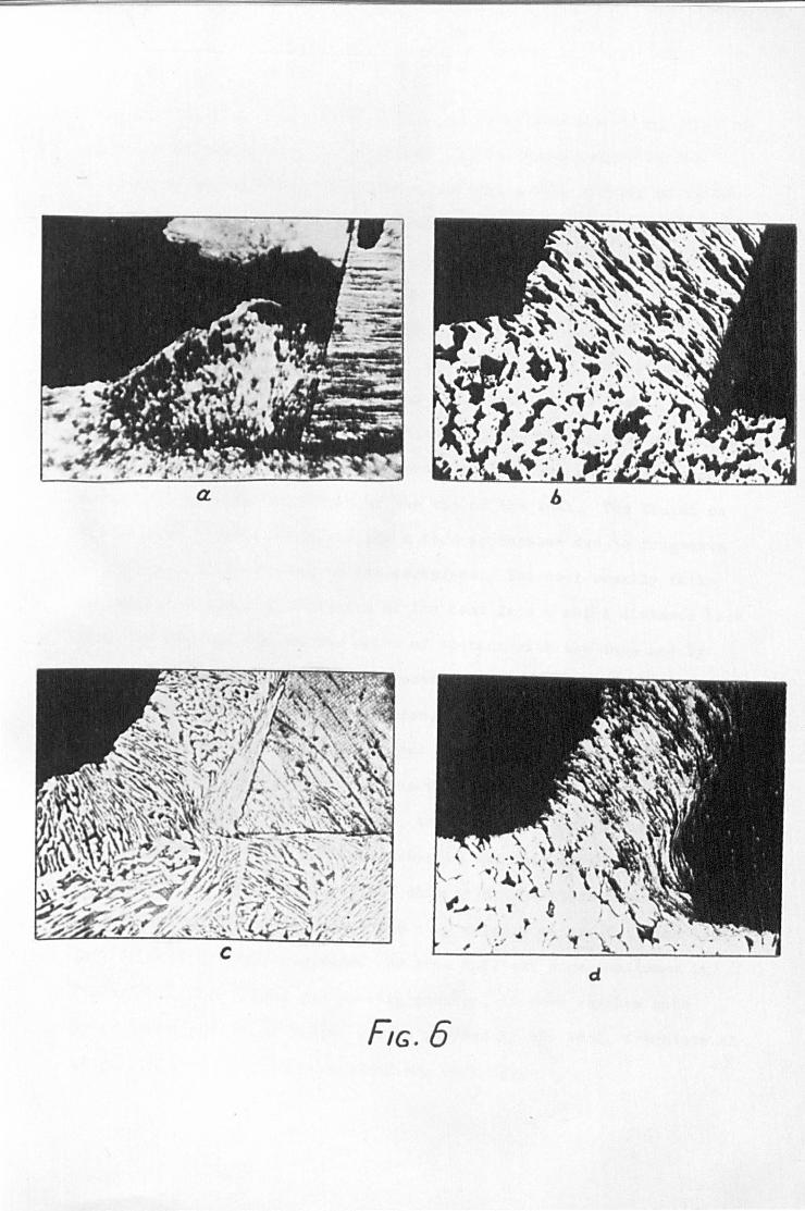
1.3.1 Discontinuous
These chips are o:f sectional. or segmented type in which
an initially compressed layer passes off with each chip segment, the
cycl.e being then repeated r Such chips are short and brittle. Dis-
continuous chips are made up of sections of roughl.y the same size
(Fig. 6a)(17) that combine to make up a long unbroken chip with a
serrated surface., Frequently, however, the separate sections split
off. The pitch of these segments depends,upon the condition of th~
operation and the material being cut. When the pitch of the segments
is small, a, good finish is produced on the workpiece. The conditions
which favour the formation of this type of chip are brittle material"
large feed and depth of cut, l.ow cutting speed and small. rake angle.
For such material too], life is longer, and to~l failure is due to
the' rounding over and wearing away of the cutting edge. These seg
mented chips are easily disposed of.
1 .. 3.2 Continuous Without Built-Up-Edge
Such chips are long ribbons of uniform thickness (Fig. 6b)(17).
A continuously moving layer adjacent to the tool face in the plastic
fl.ow occurs with relatively ductile-materia]. Conditions which are
favourable for the formation of this type of chip are ductile materi~~
small feed and depth of cut, high cutting speed, large rake angle, keen
cutting edge and high polish on tool faces(8.17). The formation of
a
d
fiG. 6

- 10 -
this type is also favoured by the use of an effective cutting fluid in
the case of high-speed cutting tools. It is characterized by the
absence of the build-up edge, and therefore, a high quality of finish
is produced. Tool life on such material is generally very good, and
tool failure may be due partly to rounding of the cutting edge and
partly to abrasion of the face close to the cutting edge.
1.3.3 Continuous With Built-Up Edge
Such chips (Fig. 6c_d)(1?) are usually long but not smooth and,
generally, considerabLy thicker than the "feed" of the tool. Chips
of this nature come from very ductile materials having medium machinability.
The metal in the chip has been severely cold-worked in machining and
a built-up edge has developed on the tip of the tool. The finish on
the work is usually rough and has a torn appearance due to fragments
of built-up edge adhering to the workpiece. The tool usually fails
because of cupping or cratering of the tool face a short distance back
from the cutting edge at the point of contact with the chip and by
abrasion of the tool flank due to contact with the fragments of built-up
edge which escapes with the workpiece. Continuous chip with built-up
edge is produced when the coefficient of friction between the tool
and the chip exceeds a certain minimum value depending upon the metal
being cut, Under these conditions, the stress on some plane in the
chip extending from the tool face down to the face of the chip becomes
equal to the shear strength of the chip metal. Failure then occurs
on that plane, and a section of the chip remains anchored to the too~
face to form the built-up edge. As this built-up edge continues to
increase in size during the cutting process, it soon reaches such
proportions that it no longer can be carried by the tool, fragments of
it pass off with both the chip and the workpiece.
- 11 -
1.4 DISCONTINUOUS CHIP FORMATION
It is generally understood that a brittle material is more
liable to produce discontinuous chips than a ductile material, but
some ductile materials will produce continuous, discontinuous and
partially discontinuous chips depending upon the cutting conditions.
Cook, Finnie and Shaw(16) classified the discontinuous chip
into two types. They distinguished between the cracks that were just
visible under the microscope in machining ductile materials and the
completely discontinuous chip where the material is removed in the
form of separate segments. The fracture is either of the ductile
shear type or the brittle tensi~e type. They stated that completely
segmented chip formation is entirely different from that of contin-
uous cutting, being better described as a periodic extrusion rather
than one of simple shear.
Field and Merchant(15) noted that the discontinuous chip
was, formed during the machining of brittle materials like cast iron
or when cutting ductile materials at low speeds and without cutting
fluids. They suggested that the basic difference between the form-
ation of continuous, and discontinuous chip was that instead of shear
occurring ahead of the tool continuously without fracture, rupture'
occurred intermittently on the shear plane thus introducing new
factors into the geometry o'f chip formation.
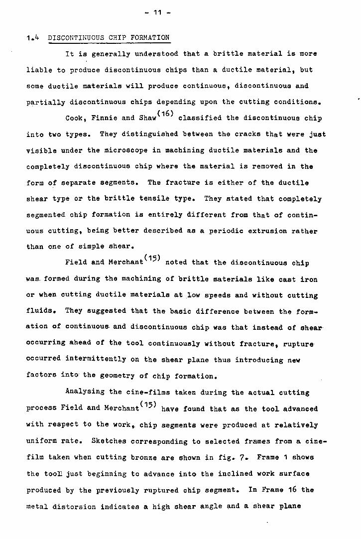
Analysing the cine-films taken during the actual cutting
process Field and Merchant(15) have found that as the tool advanced
with respect to the work" chip s.egments were produced at relatively
uniform rate. Sketches corresponding to selected frames from a eine-
film taken when cutting bronze are shown in fig. 7. Frame 1 shows
the tooll just beginning to advance into the inclined work surface
produced by the previously ruptured chip segment. In Frame 16 the
metal dis torsion indicates a high shear angle and a shear plane

t-... .
....

- 12 -
extending to the inclined work surface~ As the tool advances further,
the shear angle decreases rapidly so that by Frame 20 the shear plane
has extended to the horizontal surface. This is indicated by the
start of the curvature of the surface. Still further advance of the
tool results in a continuing decrease of the shear angle till rupture
occurs along a shear plane thus producing a chip segment as in
Frame 39. This is the end of the cycle which then repeats itself.
Investigations carried out by Bridgman(30 ) have shown that
the amount of plastic shearing strain necessary to produce fracture
increases as compressive stress is applied to the shear plane. The
relationship between the shearing strain required for rupture and
compressive stress is roughly of the form:
= Eo + K S n
where, E. r is the strain required to produce rupture, E.o is the shearing
strain required to produce rupture at zero compressive stress~ K is
the slope of the shearing strain and compressive stress curve and S n
is the compressive stress acting perpendicular to the shear plane.
Fracture will thus occur on the shear plane causing a discontinuous
chip whenever the shearing strain £ which (assuming the shear plane
model of continuous chip formation) is given by
E.. - cot¢ +
( c/.. = rake angle
¢ = shear angle)
becomes equal to or greater than E. • r
This rupture condition can be expressed mathematically by
combining equations (1.3a) and (1.3b)~ bearing in mind that the
shear angle at rupture is ¢1; hence:
cot ¢ 1 + tan (¢. -0\) ~ E. 0 + K S n (1.4)

- 13 -
Field and Merchant(15) claimed that to a first approximation,
equation (1 •. 4) establishes the value of the minimum shear angle¢1 at
which fracture will occur when cutting a given material. They argued
that as the tooL enters a cut and advances into the metal, the shear
angle will first fall due to increasing friction between chip and
tool and that if, during this process the shearing strain rises to
a high enough value or the compressive stress drops to a low enough
value,. or both, to. satisfy equation (1 •. 4)" then a discontinuous chip
will result. If, on the other hand, the equilibrium value of the
shear angle ~is arrived at before the shearing strain rises high
enough or the compressive stress falls low enough then the chip will
remain continuous. Field and Merchant(15) noted that although this
qualitative argument based on equation (1.4) is sound enough, the
actual results given by the equation (1.4) are in poor agreement
with experimental observations. This lack of agreement. appears
to· be due t~ the inadequancy of the shear plane concept.
By treating frictional conditions which varied from smooth
(31) to perfectly rough, Lee has found that the shear angle was almost
independent of friction; this suggests that the decrease in magnitude
of the shear angle, as observed by Field and Merchant(1 5), is not
due to the friction and may be associated with the extension of
plastic flow to the initial work surface.
Piispanen(13) has discussed the formation of the discon-
tinuous chip from the standpoint of ordinary chip formation and
concluded that the shear angle is initially high and decreases as
the cut proceeds, finally reaching a value corresponding to a shear
s~rain sufficient to cause fracture.
From series of experiments by Cook, Finnie and Show(16) it
was found that the normal stress on the shear plane, as influenced
. by rake angle or tool friction, is an important variable in determining
- 14 -
whether a chip will be continuous or discontinuous.
Benerjee and Palmer(32 ) concluded that the formation of
discontinuous chips when cutting En9 steels has been shown to be
accompanied by intermittent sticking and slipping of the chip on the
rake face of the tool. During the early growth of the chip a dead-
metal zone or bui~t-uw edge developed in contact with the too~.
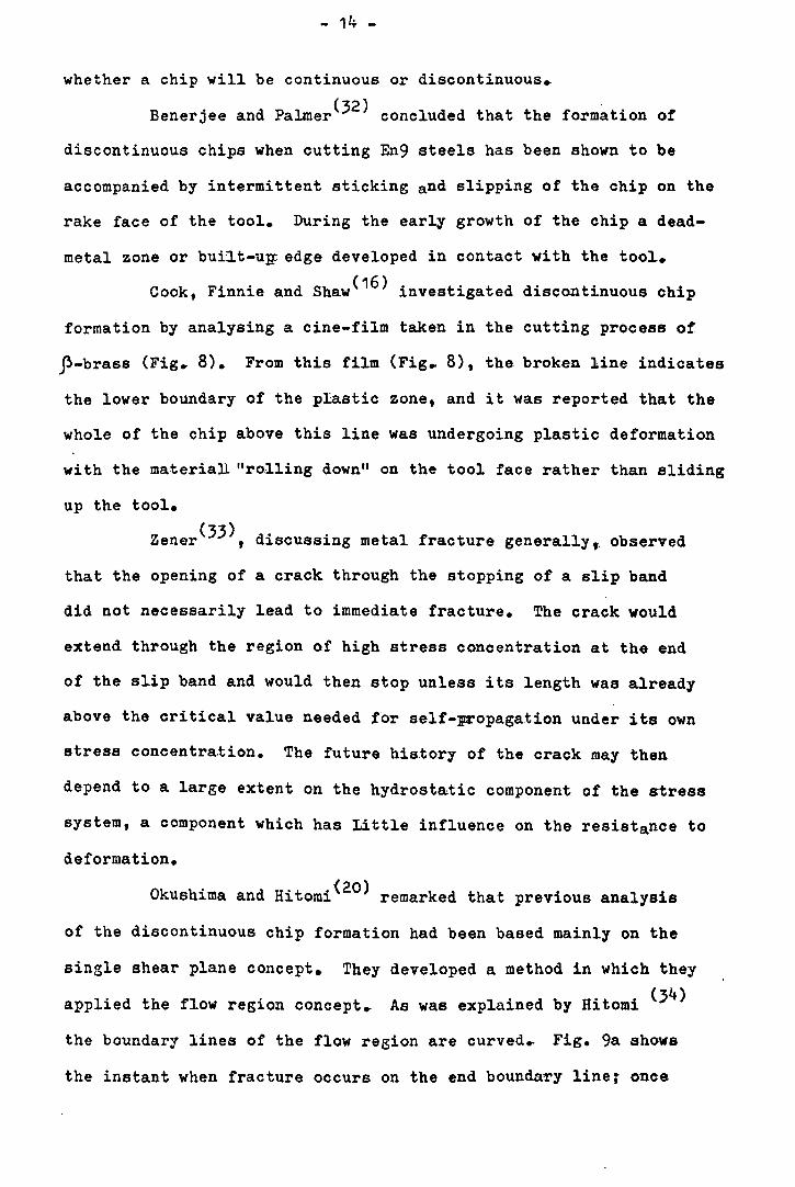
Cook, Finnie and Shaw(16) investigated discontinuous chip
formation by analysing a cine-film taken in the cutting process of
p-brass (Fig. 8). From this film (Fig. 8), the broken line indicates
the lower boundary of the pIas.tic zone, and it was reported that the
whole of the chip above this line was undergoing plastic deformation
wi th the materiall "rolling down" on the tool face rather than sliding
up the tool.
Zener (33), discussing metal fracture generally t. observed
that the opening of a crack through the stopping of a slip band
did not necessarily lead to immediate fracture. The crack would
extend through the region of high stress concentration at the end
of the slip band and would then stop unless its length was already
above the critical value needed for self-propagation under its own
stress concentra.tion. The future history of the crack may then
depend to a large extent on the hydrostatic component of the stress
system, a component which has Little influence on the resistance to
deformation.
Okushima and Hitomi(20) remarked that previous analysis
of the discontinuous chip formation had been based mainly on the
single shear plane concept. They developed a method in which they
applied the flow region concept. As was explained by Hitomi (34)
the boundary lines of the flow region are curved.. Fig. 9a shows
the instant when fracture occurs on the end boundary line; once


FLOWR£CION
TOOL
a)
hJ
F'G.9 EXPLANATION OF lJI5CONTINI10IJS CHIP FORM/fTIQJ(
WIRHPI£t£ o
FiG. 10
ANALY$16 OF 1)ISCIJHT/.NUOUS CHIP FIIR/tIATIIIN IJASErJ IIJ( FlIIW R£GIOII CIJIIC'EPT

- 15 -
fracture has occurred, a fragment of the discontinuous chiD flows out
along the tool face without any restriction;, the instant fracture
occurs, the shear stress decreases below the breaking point (limit)
and a new chip is to be formed.
This behaviour and the cutting process are almost the same as continuous
chip formation except that fracture occurs when the shear stress on
the boundary reaches the breaking point (limit) again as cutting proceeds.
At the very initial stage, the workpiece which has an initial. free
surface at OB due to previous fracture is not cut immediately, but a
portion of the workpiece near the cutting edge rises up to some degree
so· that some part OB' of the fracture surface OB contacts the toolL face
and the remaining part BB' contacts the previous fragment as shown in
Fig. 9b.
The shear stress and strain are minimum at the starting boundary
line OA and maximum at the end boundary line OB. The cutting force
is small at the initial stage' and as cutting progresses it increases.
Whenever the maximum shear stress on t~e boundary line increases
enough to exceed the breaking point (limit)~ fracture occurs. The
process is repeated and fragments of discontinuous chip are formed one
by one' ..
Fig. 10 shows orthogonal cutting, with depth of cut t1 and
tool rake angel~. The inclination of the starting boundary line ¢1
and that of the end boundary line,. namely a· line at which fracture
accurs, ¢2' are deduced theoretically in the following manner.
Since the work material should strain-harden when fracture
occurs such as in the discontinuous chip formation, the rela.tion
between shear stress '[ and shear strain l may be assumed as:
where 1: is the shear yield stress,. k and m are constants showing o
degree of strain-hardening of the material.

- 16 -
The mechanism of discontinuous chip formation is described as
foLlows: a moving p~ticle in the undeformed work corresponds to
position 0 (Fig~ 11) and when it reaches the starting boundary line
it corresponds to the position M due to the yield of the metal in
shear. When a particle passes into the flow region, it changes its
location from M to N continuously along the curve unti~ it reaches
the breaking point N. This corresponds to the end boundary line,
i.e. the fracture line at which fracture occurs periodically, and
a discontinuous chip is formed.. Thus, the average shear stress
must reach its maximum va~ue at the end boundary line of the flow
region.
Assuming that the shear stress distributes uniformly on the
radial plane in the flow region, the shear stress on an arbitrary
radia~ plane OP (Fig. 10) is given by:
t[= R Sin ¢ Cos (¢ +d.-fi)
bx (1.6)
where R is the maximum cutting force with which fracture is about to
occur, b is the width of cut and (X) is the distance from an arbitrary
point P on the free surface of the flow region to the horizonta1 lin~
through the cutting edge.
This reaches a maximum when the inclination angle of an
arbi trary radial plane ¢ becomes equal to' the inclination of the end·
boundary line ¢2 t i.e. from the condition
(dr ) = 0 d¢ ¢ = ¢2
the following equation was obtained
1 x
dx d¢ :: Cot ¢ - Cot (¢ + d- -./!J ) (1.8)

<::) 2. - 5531:115 l:IV3HS
~ I ~ -« ~ V1
a: ~ :x: tn
~ • ~
~

- 17 -
Geometrically on the other hand:
1 dx .11) X d¢ = Cot ¢ - Cot (¢ + T
Hence for ¢ = ¢2
1 dx
x d¢ =
where ~2 is the value of ~at the end boundary line.
(1.10)
Since the end boundary line of the flow region in the ease
of the discontinuous chip formation is a sliR-line with fracture,
it makes an angle of 450 with the free surface: .J1
1fr2 + ¢2 = 4'
From equation (1.8 and 1.11) .Jr
¢2 = 4' + ci. -../3
(1.11)
This equation shows the condition at which fracture occurs if a
discontinuous chip is formed. The following expression for ¢1 waa
obtained in a similar manner:
Using the strain-hardening slip-line theory to examine dis
continuous chip formation, Enahoro and Oxley(35) carried out an
investigation of the hydrostatic stress distribution in the plastic
zone. Various depths of cut were taken covering the range of chips
from continuous to discontinuous and keeping all other conditions
constant. The hydrostatic stress was found to vary from compression
at the outer free surface to tension near the cutting edge; the
magnitude of the tensile stress was shown to be important in deter-
mining whether or not the chip became continuous.

- 18 -
It is found in practice, that small changes in the cutting
conditions can cause a transition from continuous chip formation to
discontinuous chip formation. For example when machining a ductile
material, a decrease in the rake angle, an increase in the feed or
depth of cut, or a decrease in cutting -speed, can cauae a transition
from a continuous to a discontinuous chip.
Inasmuch as the normal stress on the shear plane is inherently
relatively less for small values of rake angle, the tendency to cut
discontinuously increases with decreased rake angle.
An increase in cutting speed sometimes will cause a discon-
tinuous chip to become continuous. Increase in the cutting speed
will cause an increase in the shear strain required to cause
(17) fracture • )
It is normally found that the tendency toward discontinuous
chip formation increases with the increase in the depth of cut.
Sh d F ' ,(36) b d ' t 'l t t aw an 1nn1e 0 serve 1n many ma er1a s ests hat when the
specimen size is made very small, higher yield and flow stresses
are obtained.
It is significant to mention that the use of chipbreaker&
can cause a continuous chip to become discontinuous (broken) without
actually changing the existing cutting conditions. This process wil~
be discussed in detail later in this' work.
1.5 GENERAL REMARKS ON THE PARAMETERS INFLUENCING CHIP FORMATION
PROCESS
1~5.1 Influence of Rake Angle on the Chip Formation Process
Chip formation is highly influenced by the rake angle. This
influence is directly observed through the change in the direction of
the chip flow and indirectly through the change in the coefficient ~f
friction between the chip and the cutting face of the tool.

- 19 -
The presence at the built-up edge weakens the influence of tha
rake angle on, chip formation. A similar effect is observed when the
hardness of the machined material. is increased(17).
Figs. 12 and 13 demonstrate the effect of rake angle on the
chip discontinuity and chip formation forfo -brass and magnesium as.
observed by Cook, Finnie and Shaw(16).
1.5.2 Influence of a Built-Up Edge on Chip Formation Process
Since the built-up edge occurs on the cutting face of the tool
it therefore changes the direction of the chip flow, increasing the
effective rake angle. This effect is similar at both low and high
cutting speeds.
The buiLt-up edge is significantly affected by the temperature.
It was found(37) that when mild steel is cut, the built-up edge reaches'
the maximum size at a tool-chip contact temperature of about 3000 C,
then gradually decreasing and finally disappearing at a tempera'ture of
about 6000 c. This could be explained by softening due to recrystalizing.
HOShi(38) concluded from a wide range of experiments that the
formation of built-up edge depends on cutting conditions and on work-
piece and tool materials.. He recognized three phenomena caused by the
formation of built-up edge; increase in the effective rake angle, o.ver
cutting and deformation of the free surface.
Nakayama and IgUChi(39) concluded that the generation of the
built-up edge is related to the cutting temperature and not to the
cutting speed and the built-up edge disappears over the temperature
range above the recrystalization temperature of the work material.
This is true for high range of cutting speeds when the effect of the
temperature is significant. Okoshi and Sata(40) have found, experi-
mentally, a critical speed at which the built-up edge disappeared for
different cutting conditions.

" (J I

~
'." "'-,

- 20 -
Mayer and Cumming(41) showed that stable built-up edge may
exist over a wide range of cutting conditions and depends strongly
on cutting speed, rake angle and undeformed chip thickness.
1.5.3 Influence of Friction on Chip Formation Process
The coefficient of friction in metal cutting is often greatly
different from that obtained with the same metal pair in conventional
sliding friction experiments. It is shown that a coefficient of
friction is inadequate to describe the friction process in cutting,
being mainly an indication of the normal stress on the tool face and
thus, strongly dependent on the shear process in cutting.
At the present time the most generally accepted theory of dry
(42) friction is a composite of contributions due to Holm ,Ernst and
Merchant(43) and Bowden(44). According to this picture of friction,
sliding resistance is viewed as being composed of threw factors:
(1) A mechanical inter-locking of surface asperities.
(2) A ploughing of the surface asperities of the harder ~f
the two metals through the softer.
(3) A welding o,f the surface asperities of one metal to the
other, resulting in metallic junctions.
For relatively smooth surfaces such as we have in meta~ cutting,
experimental evidence(44, 45) would indicate that frictional resistanc~
is primarily due to the shearing asperities (factor 3), while factors
1 and 2 are insignificant.
Kobayshi and Thomsen(46), using tools with controlled tool
chip contact areas, have revealed that for SAE 112 steels and for a
wide range of cutting speeds, the friction on the rake face of the tool
is explainable by the junction model with possible superimposed general
plastic flow above the junctions. They have revealed also that the
friction mechanism at the flank-wear contact area was essentially the
same as that occurring at the tool face.

- 21 -
The mean coefficient of tool face friction has a similar effect
on the chip formation process at both high and ~ow cutting speeds and
an increase in the mean coefficient of friction causes an increase in
the angle of action which results in a rise in the cutting forces.
Rozenberg and Yeremin(47, 48) have concluded from series of
experiments using different cutting conditions for different cutting
materials that the tool-chip contact temperature has a great effect
on the mean coefficient of friction at high speeds. They showed that
the change in the coefficient of friction is related to the built-up
edge process. The mean coefficient of friction reached its maximum
o at temperature of about 300 C, when the built-up edge reached its
maximum size.,
zorev(37) and Isayev(49) showed that in genera~, at the point
where the chip touches the front face of the tool, external sliding
is replaced by internal shear~
Shaw, Pigott and Richardson(50 ) on the basis of experiments
with various cutting fluids, established that equal mean coefficient
of friction and cutting ratios do not correspond to equal temperatures.
1.6 IDEALISATION OF MATERIAL
An ideal material is the one that flows at a constant yield
stress. The strain - stress diagram for such a material is shown in
Fig. 14, where ~ is the yield shear stress flow. For such a material, o
there is no permanent deformation while the shear stress is less than
Lo' Points 0; 1; 2 and 3 correspond, respectively, to the work region,
the starting boundary line. the end boundary line and the chip region.
In a strain hardening material whose flow curve is represented in
Fig. 11, shear stress on either side of the line would not be in equil-
ibrium, so shear along a single line is not possible. A moving metal
particle in the undeformed work corresponds to the position 0, Fig. 11~
and when it reaches the starting boundary line, it corresponds to the
position M due to the yield of the metal in shear. When a metal

.. ~ ~
'" V)
'ro(~ 2-.. ~ 12 STATIC TEST __ - ;;:::::.---E)
.---- ----~ -----
N , (J) (J)
W
01 3~
51-lEAR STAAIN-Tf
fiG. 14
~ , .,..,,~ .."...... -'" CUTTING TEST
N ." ./' V) 9 /~/
ij/ lJ) I..iJ ~ V) 6 a: « "'" ::t: 3 If)
#'
au 0.1 ~2 0.3 a4 a5 Q6 0.7 Q.8 o.g 1.01.1 1,2 SHEAR 5 TAAIN-;r
F,G. 15

- 22 -
particle passes into the flow region, it changes its TIocation from the
position M to position N continuously along the curve until it reaches
the breaking point N~ The breaking point N corresponds to the end
boundary line, i.e. the fracture line, at which fracture occurs period-
ically. Fig. 15 shows the shear - strain diagram for carbon steel.
In this figure the stress - strain diagram for the same material in a
static materiaL test is obtained from experimental results of the
relation between twisting moment and specific twisting angle by Ludwik's
th d(51) me 0 •
- 23 -
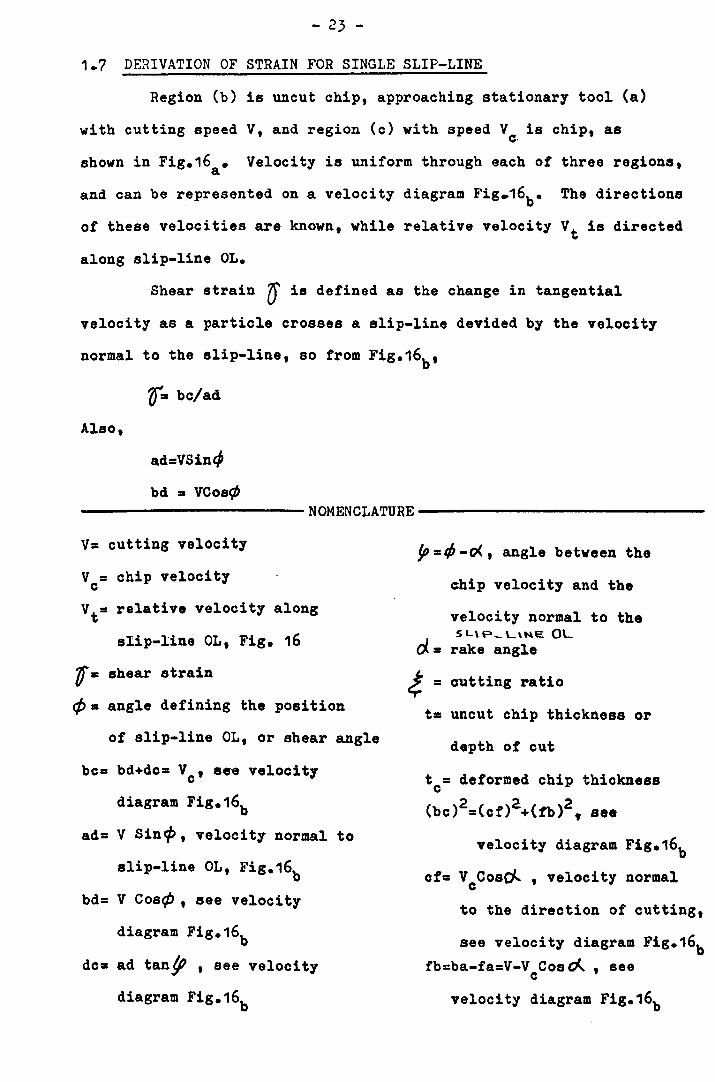
1.7 DERIVATION OF STRAIN FOR SINGLE SLIP-LINE
Region (b) is uncut chip, approaching stationary tool (a)
with cutting speed V, and region (c) with speed V is chip, as c·
shown in Fig.16a • Velocity is uniform through each of three regions,
and can be represented on a velocity diagram Fig.16b • The directions
of these velocities are known, while relative velocity Vt is directed
along slip-line OLe
Shear strain ~ is defined as the change in tangential
velocity as a particle crosses a slip-line devided by the velocity
normal to the slip-line, so from Fig.16b ,
r. bc/ad
Also,
ad=VSincl
bd =- VCos¢ ----------------------NOMENCLATURE-----------------------------
V= cutting velocity
V = chip velocity c
V t = re·la ti ve veloc i ty along
slip-line OL, Fig. 16
'D = shear strain
¢= angle defining the position
of slip-line OL, or shear angle
bc= bd+dc= Vc ' see velocity
diagram Fig.16b
ad= V Sincp, velocity normal to
slip-line OL, Fig.16b bd= V Cos¢, see velocity
diagram Fig.16b
dc=- ad tan~ , see velocity
diagram Fig.16b
JP = t/J -0<, angle between the
chip velocity and the
velocity normal to the 5 L\ P_ L'ME OL
rake angle
cutting ratio
t= uncut chip thickness or
depth of cut
tc= deformed chip thickness
22:2 (bc) =(cf) +(fb) f see
velocity diagram Fig.16b
cf= VcCosol , velocity normal
to the direction of cutting,
see velooity diagram Fig.16b fb=ba-fa=V -V Cos cA , see c
velooity diagram Fig.16b

L
(b) • V UftCUT CHIP
a)
v f VELOCITY DIRGRRNI
b)
FIG. 16

- 24 -
dc = adtan tp = V Sin¢ tan y; But,
And
bc = bd + dc = V Cos¢ + V Sin¢ tan(cP .cJ..)
Hence, fI V Cos rj; + V Sin ¢ tan( ¢ - cj...) u = bc / ad • V Sin ¢
I: Cot ¢ + tan ( ¢ - d.. )
It is an easy matter to differentiate equation (1.14) to get the
value of ¢ which gives minimum strain, 1> = ?f/4 + d./2, which means
that the shear plane bisects the angle between the tool face and
direction of cutting, implying ratio? = 1, but this is not of much
direct practical value. It is noted that the cutting ratio follows
by expressing thicknesses t and t in terms of length OL, c
~ = tc/ t = Cos (¢ • (}..)/ Sin ¢
which transposes to
Co,t¢= t Secci. tan cf.- (1.15)
Equation (1.15) gives a practical means of' finding shear plane
angle.
Another derivation of strain from the velocity diagram
may be of interest. Drop perpendiculars ad and ct as in Fig.16b
(velocity diagram). By Pythagoras,
(be)2 = (ct)2 + (tb)'
But, as
et I: V Coa ~ , and tb = V • Y Sin cf... • we- have e c (be)' = (Yccosc')2 + (V • Vcsinot)2
(bc)' • V2 + v' . ,VV Sino( c e:
However~ the area of the outer triangle is given by, 1 1 ~ V x cf~ be x ad, giving bc x ad = V V Cos cJ...
e Using these results. we can now find the strain in terms of

- 25 -
velocities and rake angle,
t = bc/ad = (bc)2/bc •ad = [v2 + v~ - 2VVcSin~/ VVe-cose}.
and as the' cutting ratio is defined ~= V/vc ' we get strain
0'= ( ~ + i) See~ - 2tan~ (1.16)
Naturally, equations (1.14),(1.15) and (1.16) are compatible as
may be verified.
1.8 STRAIN FOR A PAIR OF SLIP-LINES
Suppose that chip speed represented by point c is fixed
Fig.17a - This speed is attained after slip along tvo lines ON
and OM with an intermediate region e. As compared with the single
slip-line regime, ve now have tangential velocities be and ec
( Vt1 and Vt2 Fig.i7b ) slightly increased, while the normal
velocities ad1 and ad2 are appreciably reduced. Hence the total
strain in the chip, given by (f= be/ad1+ec/ad2 will be increased
over the value appropriate for shearing on a single plane_
NOMENCLATURE
Vt1 = relative velocity along slip-line ON, Fig.17
Vt2 = relative velocity along slip-line OM, Fig.17
cPt = shear angle defyining the position of slip-line
¢2 = shear angle defyining the position of slip-line
ad1 = velocity normal to slip-line ON, Fig.1?b
ad2 = velocity normal to slip-line OM, Fig.1?b
ON, F~g_,?
OM, Fig.1?

CHIP
(b) • V UNCUT CHIP
a)
b ~-~~-------~a. V
VELOCITY ~JAGRRNI
b) FIG. 17

- 26 -
1.9 STRAIN RATE IN FAN REGION, SERIES EXPRESSION FOR CURVATURE AND NUMERICAL INTEGRATION FOR A PARTI
CULAR EXAMPLE
In any particle,. strain rate in polar-coordinate is
given in terms of velocities by:
g ~ = ~ ~¢ + ; g;; - ~~ However, velocities in the fan region ONM (Fig.18) are assumed
not to vary with radius, so the first term a VtP/ o~ is zero.
We can also write,;
00' "~oCb 'Or..!t ar = o¢> ?)r = o¢' r
Hence
1 ~-1 V; ()¢ Let perpendicular to radius R make angle 8 with the tangent to the
surface NM at some point M as in Fig.18. As velocity at point M
must be directed along the surface, we have
8 1 dR V,. tan = - ~ ~ = - ~' hence
NOMENCLATURE -------------------------
o = shear strain
T = tim .. rate
~ ~ angle of initial slip-line II
GP, = angle of the final slip-line
V~ and Vr • velocities in ~ and rS = angle between the perpendicular
directions
r = radius of location of any
particle
to radius R and the tangent
to the surface NM at point M
V = cutting speed
R = radius from 0 to surface NM~ t =.uncut chip thickness
Fig.18 corresponding to the bCP= small variable increment of
final slip-line shear angle
Ra= radius from 0 to surface NM'A9b= angle of the whole fan
Fig.18 corresponding to the
initial slip-line
9' = angle- of any slip-line or
general shear angle
(j.. = rake angle
Rand b = constants a
&2 = c:onstant
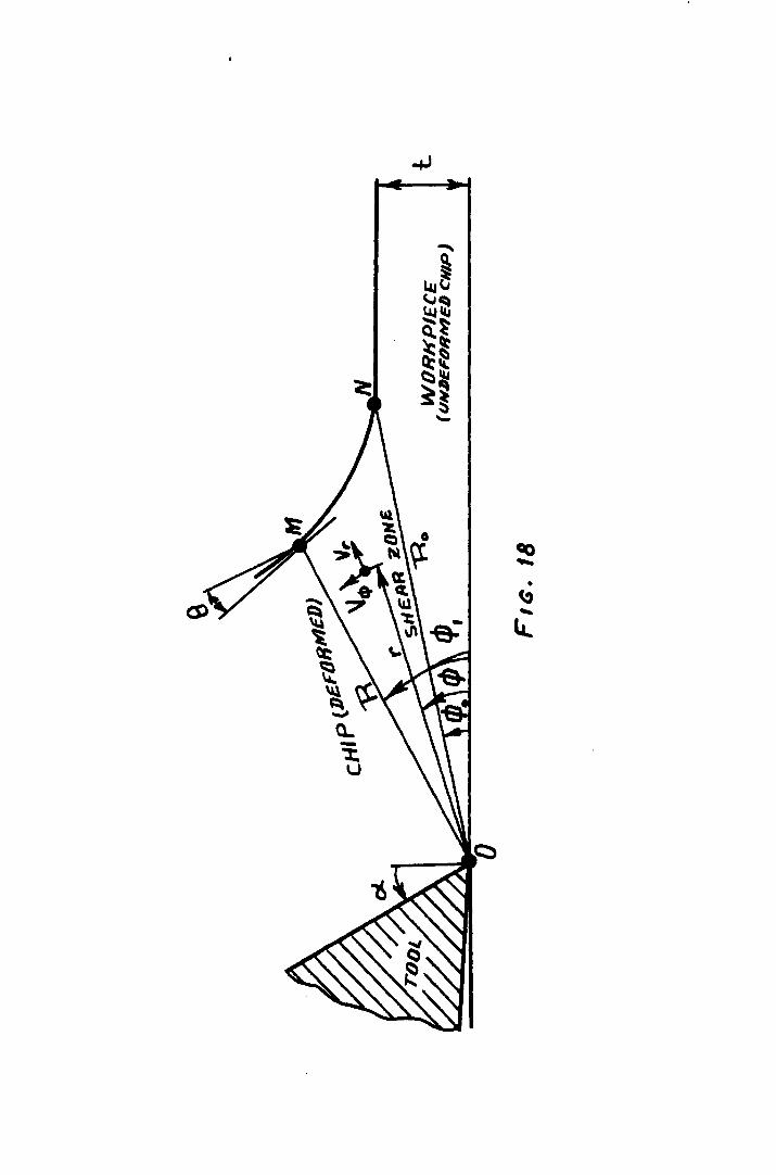
Q.. -"l:. u

- 27 -
However continuity requires that
R V1' = V t
We now have these velocity components:
V¢ Vt and V Vt dR
= -r r = -:T <IT R
Hence equation (1.17) for strain rate becomes:
air R d (1 dR) 1 o¢ = ~ ~ '"d¢ -
It is very easy to see that any segment of the surface profile
that happens to be straight, and is consequently expressible as
R = R Sec(~+ b), gives zero strain rate. This is to be expected, a
as strain rate in both workpieca and chip is zero at all points
outside the deformation fan. So it is seen that straining occurs
only while the surface is curved. The total shear strain is now
obtained by integrating from initial to final slip-lines,
r r¢'.£f.. U = J fI CJ¢ d rp
9'& The upper limit is obtained from Fig.18 in terms of rake angle,
when rP, + (} = d... , or -tanB = tan(~ -cO = [t :~j¢=tP, To procced further with this theory, some particular shape ot
surface R(cp) must be selected. Let us take the relation:
R = Ro [1 - (¢ - ¢,,)Cot tlJo + a2 ( cfJ _ ¢p2] Taking the first term as unity gives R = Ro when ¢ = ¢(J. The
second term is provided with coefficient Cot4bto ensure that there
is no discontinuity in slope at the initial point of the curve (such
a discontinuity would imply a sudden increase in strain across the
initial slip-line, so that integral (1.19) would not be adequate).
The coefficient a2 is arbitrary, but needs to be )(~ + Cot2¢.) to
ensure that the surface curves upwards. Higher terms in the series
may be taken, but not essential. It is now straightforward to apply
(1~18) and (1.20) to (1.21) to get strain rate:
- 28 -
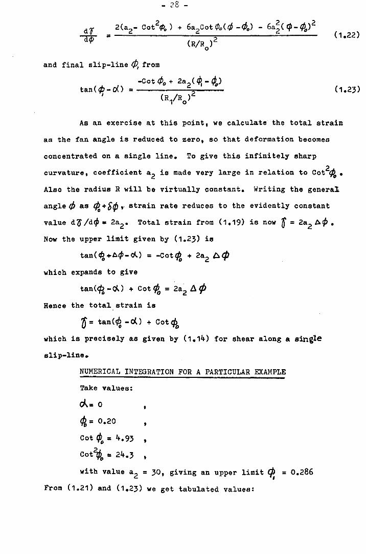
and final slip-line 4J, from
-Cot cPo + 2a2 ( ¢, - ¢,,)
(R1/Ro)2 tan(¢-oO =
I
As an exercise at this point, we calculate the total strain
as the fan angle is reduced to zero, so that deformation becomes
concentrated on a single line. To give this infinitely sharp
curvature, coefficient a2 is made very large in relation to cot2~ •
Also the radius R will be virtually constant. Writing the genera1
angle t/J as ~+Srp ,. strain rate reduces to the evidently constant
value d(f /dq, = 2a2• Total strain from (1.19) is now t = 2a2 ACP •
Now the upper limit given by (1.23) is
tan( ~ +A¢- d-.) = -Cot ¢o + 2a2 A t:/J
which expands to give
tan(cPo - ~) + Cot ¢{, = 2a2 Jj. ¢ Hence the total strain is
'0 = tan(~ - d..) + Cot eli, which is precisely as given by (1.14) for shear along a single
slip-line.
NUMERICAL INTEGRATION FOR A PARTICULAR EXAMPLE
Take values:
rA=O , 4/, = 0.20 , Cot ¢() = 4.93 , cot~ = 24.3 , with value a2 = 30, giving an upper limit cP, = 0.286
From (1.21) and (1.23) we get tabulated values:

-.29 -
cjJ R/R 0
df/dfj;
0.20 1.000 11.4
0.21 .954 22.0
0.22 .. 913 32.5
0.23 .879 43.0
0.24 .852 53.0
0.25 .829 62.0
0.26 .812 68.0
0.27 .802 73.0
0.28 .798 75.0
0.286 .798 74.5
On integrating, the final strain is found to be ~= 4.32. This is
somewhat higher than the value obtained from (1.14) by assuming that
strain occurs exclusively on the final slip-line ¢.= 0.286, which I
is 0= 3.65. This makes clear the insufficiency of Zorev(17)
analysis of the distribution of shear strain in the chip formation
zone, which implies that the final strain is determinate from the
final slip-line alone.
The width of the fan is seen to be dependent on the value
taken for constant a2 • Within this fan, alternative strain distr
ibution could be obtained by taking higher terms in the series.
For deciding which distribution is correct, some appeal would have
to be made to stress equilibrium within the fan, and to the stress-
-strain curve for the material.

- 30 -
1.10 HEASURE OF STRAIN
Shear strain "Engineering definition" is defined as the
reduction in angle of the outer corner of element
?I =fli2-/3 u xy
Shear strain "Mathematical definition"
So
E. 1"'" = -:-(/1/2 -fo) xy ~
II = 2 ~ Uxy xy FIG. A
Equivalent shear strain ~is strain which is equal to pure
shear strain E when no other strain is present, and for any xy
combination of strains "Mathematical definition" ("" ~ [(S"E _~E)2 + (6E. _bE)2 + (bE _ bE. )2 o c:.. = x y y '- z z x + (6E )2 +
v xy 1
+ (6'E ) 2 + (OE )j 2' yz zx
or "Engineering ll shear strain
__________ NOMENCLATURE --------------
"Ii "Engineering" shear strain Uxy=
E. -" Mathematical" shear strain xy-
SE ,$~ ,&~ = direct strain increments x y -Z
&If xy'bOyz'bOzx= shear strain increments
b"6 = equivalent IIEngineering" shear
strain component
EE = equivalent "Mathematieal" shear
strain component
u = horizontal movement of upper
side of element AB, Fig.19 a
1V= swing angle of the side
OA of the element, Fig.19a
c = vertieal movement of the
element
x,y = co-ordinates defying
the position of the element
L = current length of the
element after extension
L = original length of the o
element before extension
r- u OL = length increment 0'\.1.. = increment of horizontal movement
~ = corner angle, Fig.A

- 31 -
or
(60)2 = J(S~ -dE )2+ (cSf _ at )2+ (5€ -0£ )~ +(~o. )2+(~f )2+(~,£ )2 bL x Y Y z z x J xY yz zx
1
~O = rL3 J(O€ -J€ )2+ lJ>E -if )2+ (JE -~E )21 +(6! )2 +C6[ )2+~jf >j 2 (1.24) L L x Y Y z z x J xy yz I4zx
However r for plane strain deformation at constant volume
$£ =&0 =&0' = 0 z yz zx
$£ = -<Sf Y x
Therefore, we have 1
~-o = [.~ • .J($E - r-J£ ])2+ (-c5"€ _ 0)2+ (O-JE )21 + S 0.2J r 3t x l: Xi x x J xy 1
60 = [48t2 + 602 ]'2 x xy
Let us examine the following cases:
a) Unidirectional shearing
The upper side of element AB moves horizontally to A'B',Fig.19 , a
through distance u while side OA swings through angleV'. For any
increments ~u. the mathematical shear strain component is
(E: - 1 ( ~ + .£2... ) I: 1 OU o xy-2 oy aX 26Y
the vertical movement c being zero. As there is no direct strain
relative to the ( XtY ) co-ordinates, we have from (1.25)
00 = ~ , and n = SaO = ~ = tan lJI
b) Constant Volume Extension
At any instant, direct strain is the length increment
divided by the current length, Fig.19b
6E = #- ,o€ = 0 x ~ xY
Therefore the "Engineering" shear strain from (1.25) will be
2 ln L ~
(1.26)

y
'-_____ -x
-- -y
___ ~x ~ --
A A'
-
-
..!.if I
I I ~
o
F'G. 194
L
Lo
--- - -- -
- - - ----
FI6·l911
u
B 13'
I II
, I
I I
-- --I I I I ___ ...J

- 32 -
1.11 SHAPE OF STRAINED CIRCLE
a) For Unidirectional shear
Let point A be initially on a circle, Fig.20a , so that its
co-ordinate valuea (x,y) are related by
222 x + Y = R
This point moves distance Ax to A', as in Fig.20a , while the shear
strain 0 is imposed. From definition of shear strain for unidire
ctional shearing,. equation (1.26), we have
AX = Oy Hence the new co-ordinates of point At are
t '1't = '1'
----------------------NOMENCLATURE--------------------______ _
x,y = co-ordinates of point At fo = angle of the inclination
Fig.20 of the major axis of the a
R = radius of the initia~ circle ellipse to the line ot
(unstrained), R2 = x2 + '1'2 maximum direct strain which
Ax = distance which point A moves is at 45°, Fig.20a
when Z/shear strain is ~faa = direct strain increment
imposed, distance AA', Fig. ~Eab = shear strain increment
20a Co = logarithmic strain
0= shear strain half-corner angle, Fig.20 a
x',y' = co-ordinates of point A' 1V= angle of the inclination
on the curve corresponding of AAt to the major axis
to the shape of the strained of the ellipse
circle, Fig.20 a
rt e = polar co-ordinates of point A't
Fig.20 a
a,b = major and minor semi-axes of
the ellipse (deformed circle)

....... .......

- 33 -
we now describe the position of A' in polar co-ordinates,
x' = r Cos B , '1' = r SinS
Combining (1.29) and (1.30), we get
x = r (CosO- SinO) , y = r SinO
and using (1.28)
r2 [ (Cos e -fsinB )2 + Sin2SJ = R2
Equation (1.32) is the equation of the curve into which the circle
has deformed. If we write B =1/1 +.Ji/4- -fo , the equation (1.32)
becomes,
1 + i- 02 + (- OSin2fo + +02
Cos2ft ) Sin2?/f +
+ (-OCos2fi - + 02 Sin~ ) Cos21/1 = R2/r2 (1.33)
Equation (1.33) is recognised as the equation to an ellipse. When
the Sin27/f term vanishes, angle 7f/ will be taken from a datum line .
coinciding with the major axis, and it is seen that this is so when
anglej,S is given value
tan2fo = '0/2
Putting this value in equation (1.33), we get
1 1 '1"'2 ')("* 1 if' 2 '2 2 2
1 + "2 fJ - U (1 + "'It (J ) Cos21/f = R /r
The major and minor semi-axes of the ellipse a and
[1 r R 1 -02 +O~1 1 02 "'2 a = + 2' +1+
b = R [1 + +02 -O~1 1 '02 +~ i
b are given by
,
Some comments can now be made about these results:
Incremental direct strain referred to the ellipse axis
b€ = C/a aa a
may be evaluated from equation (1.35) and inserted into the
expression (1.25) for shear strain:
80 =~O/~ 1 + -¢02 This is obviously untrue (except attr= 0). The reason is that a
(1.35)

- 34 -
componentOEab is also present, due to the inclination of the major
axis at angle~ to the line of maximum direct strain increment,
which remains at 450• When this correction is made,equation (1.25)
is satisfied. It is concluded that the total strain is not deter-
mined from the final deformed shape alone, as the path by which the
shape is reached must be taken into account. On these grounds,
Zorev(17) analysis of the distribution of shear strain in the chip
formation zone which suggests that the final strain is determinate
from the final slip-line alone can also be criticized.
b) Unidirectional Stretching
A similar exercise can be carried out for finding the final
shape of a circle deformed by pure stretching, which indeed, an ellipse.
Instead of acircle, we now consider a square of half-diameter initially
equal to d. This is horizontally stretched to m, and vertically
compressed to n, as in Fig.20b , so that
m :I d e£ , n = d iE.
The half-corner angle ~ is given by
tan], • min = e-2E
If we suppose that shear strain is given by the cotangent of the
whole corner angle,
0= Cot2~ = (1 - tan2 ~) / 2tan ~ = Sinh2€.
This cannot be true, as we know that equivalent shear strain is given
by 0= 2E. It appears, therefore, that shear strain is given by
the cotangent of the corner angle only if <a) strain is small, or
(b) shearing is unidirectional. It is again concluded that strain
is not determinate from the deformed shape unless the mode ot
deformation is specified. Equivalent shear strain must be found
by summing components correctly related to orthogonal axes at each
stage of deformation. Finite strains deduced by switching axes on
the deformed element (as in Nadai "theory of flow and fracture of
solids") have no useful meaning.

- 35 -
It may not follow that strain hardening is uniquely
determined by the equivalent shear strain. In many metals,
unidirectional shearing is less effective in producing hardening
than unidirectional stretching. However, this is not a justification
for irregular definitions of large strain.
1.12 DIRECTION OF TEXTURE
In case of a single shear plane OM, Fig.21, the angle
between the cutting direction and the major axis of the deformed
ellipse is given by .Jj
1\= <P+ ,.-fl Angle;jG and shear strain are given by the equations:
tan2ft = 0/2 , This result seems to be in agreement with results obtained by
Zorev(17) who uses an average value of shear plane angleq, •
Structural features of an initially isotropic workpiece material
will therefore give striations in the chip at the angle;t •
When the shear plane is straight, these striation will be straight.
except possibly in a very thin smeared layer of the chip under-side.
---------- NOMENCLATURE --------------
A= angle between the cutting direction and the major axis of the
ellipse~ Fig.21.
¢ = shear plane angle
~= angle between the major axis of the ellipse and the line ot
maximum direct strain which is at 45° to the' shear plane,
Fig.21
'0 = shear strain
ct = rake angle

F'G. 21

- 36 -
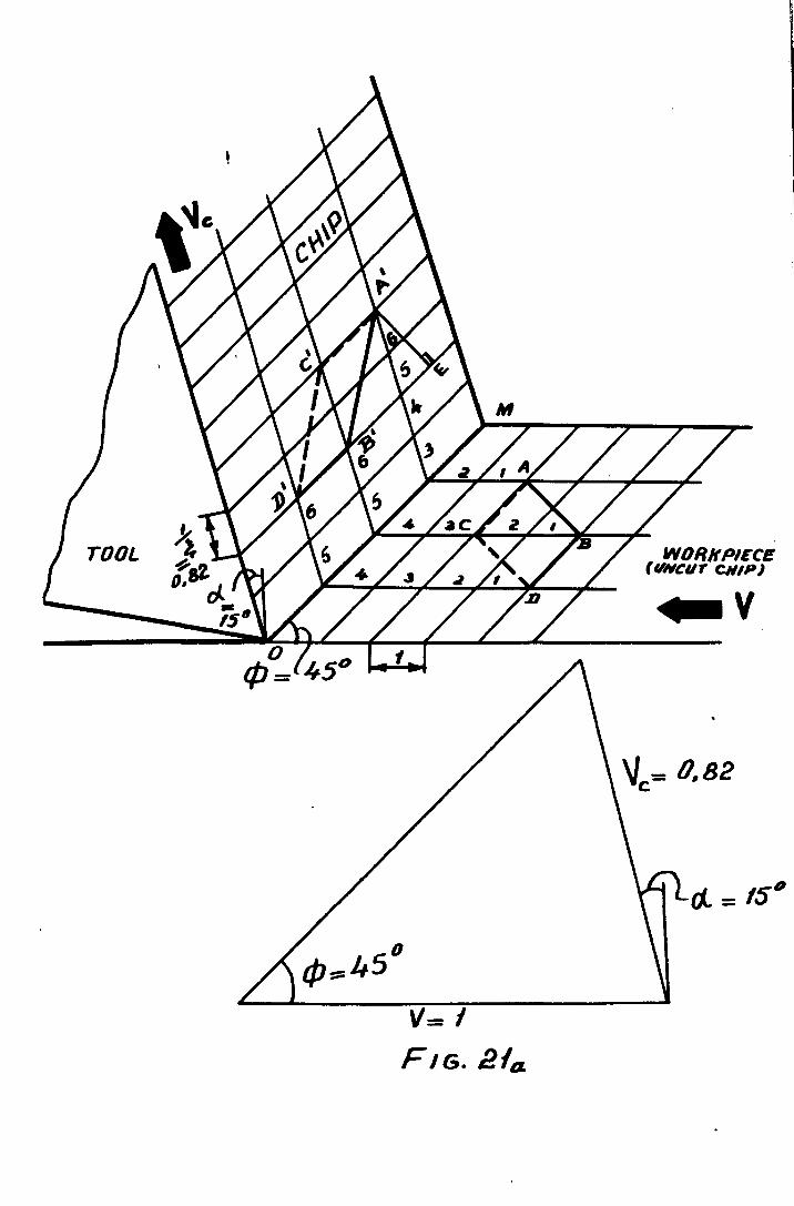
1.13 PLOTTING DEFORMED SHAPE
a) For Straight Shear Plane
Take rake angle c{= 15°, shear plane angle qD= 45°. From
veloci ty diagram, chip thickness ratio ?= 1.23 or 1/ ~ = 0.82 •
Mark off convinient units along uncut chip, and intervals
0.82 along chip, drawing lines parallel to shear plane OM, Fig.21 • a Take any line AB perpendicular to shear plane. Draw path
lines through these points. Count off a certain number of spaces
along path line (say six) for each point. to get points K and B' in
chip. Similarly for other points on a square or other figure drawn
on uncut chip. Strain in chip is given by ()= EB/EK = 1.58
(because square initially aligned with shear plane deforms by
unidirectional shear)
b) For Curved Shear Plane
In Fig.21b , the deformation is analysed for a chip thickness
ratio ~ = 1.5. rake angled= 0°, with a pair of slip-lines of fairly
large curvature. If the curvatures are equal, the tangential velocity
change at each line will be the same, as the chip has no angular
velocity. A hodograph (i.e. velocity diagram) must be drawn in ______________________ NOMENCLATURE ________________________ __
(}.= rake angle Sb= distance which the same any
¢= shear angle poin~ travels in the deformation
{,= chip thickness ratio
0= shear strain S = . c
S = distance from any point on line a
A-A to the initial slip-line,
Fig.21b V = c
region, Fig.21b
distance from the same an,.
point on deformed line B-B
to the final slip-line, Fig.21b
velocity in the chip region
V = a velocity in the undeformed t = time neccessary for any point on a region line A-A to move a distance of Sa
Vb= velocity in the deformation region
tb,tc = time neccessary for any point to move a distance of Sb and Sc
\ I
TOOL WORKPIECE (VNCur CHIP)
.. v

i
.j
. I .. _.-t+ ! I
. 'r--
I . TOOL-~--.
I ; f
! iB -1······+ ...
f· I •. -t-.
I r'" .
. I ~-~. r-
I II
+ .... r' ! I jHODDGRAPH .
,.
I
.:r.liI .. 21" i . L .. "_' .:1 ... _~ ....
- ~ -
~=1.5
A
2
"f I
WIl/IKJlIEC£ . (uliwr CNJ~ •
-A
I . i .
'1 I , I --·1
!
....!._ ._..:. ____ L-...._~l~~· _. j

- 37 -
which relative velocities on either side of a slip-line are tangential
to the slip-line, and absolute velocities are directed along the
path lines~ the path lines being i~dicated. Also, the three regions
have uniform velocity or rotational velocity (as they do not deform
internally)
Line AA deforms into line BB. This is plotted as follows:
Distance S is measured off. This is divided by velocity V to get a a
time ta. Similarly, distance Sb is divided by velocity Vb which is
measured off the hodograph, to give time tbe Times ta and tb are
now added, and the sum is subtracted from some convinient total time
t to give time t available for covering distance S. This distance c c
is, of course, got by multiplying time t by speed V. The distance c c
S is now measured off along the path line in the chip region, to c
define a point on the deformed line BB. This line does not directly
indicate the texture, but as it is seen to be curved, the texture
is found to be curved in similar way.
Under these conditions, the strain in the lower side of the
chip is extremely high (It can be easily calculated from the hodograph)
and becomes infinite when the lower slip-line arc becomes tangential
to the direction of cuttinge
The free surface can be taken at any of the path lines.
P.S. ttThe discussion given on pages 23 to follows
a eet of notes supplied by the supervisor".

- 38 -
CHAPTER 2
DYNAMOMETRY
2.1 GENERAL INTRODUCTION
One of the major objectives of the metal cutting research is
the determination of the machining forces. Recently a great deal ot
attention has been given to force measurement, and as a result dif
ferent types of dynamometers have been developed.
In designing dynamometers, two groups of requirements must be
fulfilled:
Group I
Group II
1. The construction should be such that it can be made in
the workshop laboratory with a minimum of cost and
effort.
2. Simplicity of operation and calibration.
,. Robustness.
4. Adaptability.
5. Sufficient range of application.
1. The torce components should influence the dial gauges
independently.
2 •. Sensitivity. The sensitivity of a reliable research
dynamometer should be within the range .5 - 1.0% for
~ess than 50 kg.
,. Rigidity. The mechanical parts of the dynamometer are
subjected to elastic deformation" therefore the deflections
should not be so large as to affect the cutting action.
4. Stiffness. All machine tools operate with a certain
amount of vibration, which may have large amplitudes in
certain operations such as milling and shaping.

- 39 -
In order that the recorded force is not influenced by
any vibrating motion of the dynamometer, its natural
frequency must be large (at least four times as large)
compared to the frequency of the vibration set up in
the machine tool(52 ). For purpose of analysis, any
dynamometer can be considered as a mass supported by a
spring. The natural frequency of such a system is
equal to:
'vIn = ~Ji~K/m cps (2.1a)
'vi - is the natural frequency of the dynamometer, n
K - is the spring constant lb/in.,
m - is the mass in lb •. (sec)2/in •
The natural frequency of the dynomometer in terms of
the supported weight of the dynamometer (W) is given
as:
5. There should be no cross sensitivity between the force
components.
6. For the sake of convenience the calibration line should
be linear.
7. The dynamometer should be stable with respect to time,
temperature and humidity.
8. The friction between the moving parts of the dynamometer
ahould be minimum.
2.2 TYPES OF MEASlTRING INSTRUMENTS
2.2.1 Absorption Dynamometers:
The •• dynamometer.("· 54) measure the power output of some
machines and then convert that mechanical energy into heat and
dissipate it in an easily controlled manner.

- 40 -
2.2.2 Transniesion Dynamometers:
These dynamometers provide an indication of the force or torque
passing through. There are two main types; torsion dynamometers which
measure pover transmitted to or from high speed machines such as fans,
turbo-compressors, centrifugal pumps, etc.(55) and hydraulic dynam
ometers{56 , 57) which measure and record the energy absorbed by slow
running machines of variable load such as machine tools, plungers, etc.
2.2.' Force ~:easuring Instruments::.
In these instruments the cutting forces are arranged to deflect
mechanical springs usually in the form o! stiff diaphragms, the
deflections being measured either by mechanical or electrica~ means.
Different dynamometers were designed for different operations such as
(58, 59) lathe dynamometer(58, 60) (one, tvo and three component dynamometer),
milling dynamometer(6,) planning dynamometer(64), (61 62) drill dynamometer '
etc.
The torce measurement in torce measuring dynamometers involves
( -3 -4 the measurement of small deflections 10 to 10 in.) with a suitable
calibration between the forces and the deflections.
Force measuring devices are classified as follows:
I Mechanical devices - Dial gauge indicators (dynamometers);
1. Single-component dynamometer.
2. Two-component dynamometer.
,. Three-component dynamometer.
II Hydraulic devices.
III Pneumatic devices.
IV Optical devices.
V Piezoelectric crystals.
VI Electrical devices.
1. Electronic transducer tube.
2. Ditterential transtormer~

· - 41 -
,. Strain gauges:
(a) Magnetic tube strain gauge.
(b) Unbonded wire resistance strain gauges.
(c) Bonded strain gauges.
(d) Strain rings ..
2.3 DIAL GAUGE DYNAMCMETERS
Dynamometers of this type have a very limited range of use
due to their poor stability &t medium and high cutting speeds.
The dial gauge dynamometers are capable of reading deflections in
the range of (10-3 - 10-4 in.) when functioning properly. These
dynamometers are recommended for low cutting speeds up to 10 m/min.
zorev(17) has designed a single-component dynamometer for
checking the correctness of the reading of a two-component dynamometer
used tor torce measurement and also for use in those cases where there
was need ot considerable rigidity in the lathe-instrument-tool-blank
systell.
The dynamometer is based on a plate (1) whose bottom surface
is ground to the top surface of the lathe's cross slides, Fig. (22).
Into the horizontal hole ot the tool-holder (2) is fitted a tool (3)
which is held by two bolts screwed into the top of the tool-holder.
On the round block is secured a vertical strut (4) in the top
of which i. fitted a miniature gauge (5) rests on the vertical surface
ot hardened pin which is gressed into the hole of the tool-bolder.
Under the influence of the horizontal component of the cutting
force the vertical vall or the block bends and the tool-holder moves
along the arc or a certnin circle which by virtue of the smallness of
the movement i. practically a horizontal straight line. A dial gauge
with a scale division of .001 mm was used for recording of these move
ments. It is cloar that the horizontal movements of the tool-holder
SHHFIUD UNIUI'!l'

· j", .. ,)

- 42 -
are pro~ortional to the value of the horizontal projection of the cutting
force, so the readings of the dial gauge characterise the value of the
horizo~tal projection of the cutting force.- Three strengthening ribs
(6) are wolded to the base plate to increase the rigidity of the
dynamometer and to eliminate the influence of tightening of the
securing bolts on the dynamometer's characteristics. This dynamometer
was used for measuring the load of up to 1000 kg.
The two-component dynamometer used by Zorev in his experiments
was a combination of two single-component dynamometers. In this case
the rigidity of the dynamometer is increased by welding some extra ribs.
As in the case of single component dynamometers under the
action of the horizontal projection of the cutting force the vertical
wall of the base plate bends and all the points of the tool-holder body
move along the arc of a certain circle. These movements of the tool
holder body record through a dial gauge.
Under the action of the vertical projection of the cutting
force the upper part of the tool-holder body drops. The movement of
the upper part of the tool-holder are registered by dial gauge whose
measuring pin rests rigidly connected with the upper part of the tool
holder body. This dial gauge reading determines the value of the
vertical projectio~ of the cutting force.
In order to eliminate the influence of the horizontal force on
the readings of the vertical force measuring dial gauge it is turned
in the vertical plane parallel to the tool axis. In order to eliminate
the influence of the vertical force on the readings of the horizontal
force measuring dial gauge the tool overhang is carefully selected.
Both single and two-component dynamometers have strictly
linear calibrating characteristics which coincide during loading and
unloadin3.
Experimental results showed exceptional stability of the
calibr~ting characteristics and complete reliability during operations

- 43 -
at low cutting speeds.
A dynamometer developed by the College of Aeronautics for use
with drills to measure thrust and torque was described by Town(60).
The thrust is translated through a spindle resting on a ball bearing
whose movement is resisted by a diaphragm. Deflection of the diaphragm
is then measured by a dial indicator actuated by a bell crank lever.
The torque is also translated by a spindle acting against anather
diaphragm which acts as cantilever whose deflection is measured by &
dial indicator. Both indicators read to 0.001 in. and the instrument
range for thrust is 500 lb. and torque 10 lb. in.
The above dynamometer can also be used for determination ot
power for cutting, machine efficiency, optimum tool geometry,
machinability index for power, and eff~ct of variation of drill
diameter and feed and also for comparison of cutting force relation-
ships.
Town(61) aLso described a dynamometer developed by the College
of Aeronautics, Cranfield to measure the cutting forces. The resultant
load on the toon is resolved into three components by a rocking motion
in the vertical and horizontal directions and by sliding in the back-
ward direction. The shank of the tool-holder is an incro square in
section and can hold a tool of i in •• diameter or l in. square section.
Three dial gauges with accuracy of 0.001 in. are used to record the
diaphragms deflection.
This dynamometer can also be adapted to the measurement of
power available for cutting and machine efficiency, the best true rake,
clearance or plan approach angle~ the machinability index for power,
the specific cutting capacity or the effect of variation in depth of
cut and teed.
Under conditions of slowly changing load at low cutting speed
it should be noted that dial gauge dynamometers have considerable

- 44 -
advantages over electric and hydraulic dynarno~eters in the repro-
ducibility of readings. In addition they have considerably greater
rieidity than hydraulic dynamometers.
HYDRAULIC DEVICES -------_._------In these instruments Fig.23(52 ) the forces record through
a diaphragm to a pressure gauge which indicates the value of the
calibrated force. In comparison with dial gauge indicators,
bydraulic devices have a large range of cutting speeds. They
give more accur.te measurements of the applied forces but less
rigid than the dial gauze indicators. One of the advantages of
these devices is that the force may be read at a distance from
the pressure cell.
PtEIDIATIC DEVICES -----------------One of the most accurate devices of this type is the one
which has been design~d by "Solex" (Solex claim). Solex has
designed a device called "Solex micrometer" whereby the change
in back pressure th~t occurs when a flat surface is brought into
closer contact with a sharp edged orifice are used to measure
deflections in tool dynamometers. The simplicity and reliability
are the mAin characteristics of such devices if they are carefully
supplied with a cle~nt constant pressure air.
Lomachenko(65) has described a Russian designed pneumatic
dynamometer.
The tool placed in a holder and clamped to it by two bolts.
The holder together with the tool can move in three directions perpend-
icular to each other under the nction of cutting force components arisins
in turning. The holder moves on ball bearings to minimize friction.
Foree components are tran~mitted from the holder to the
correspondine transducers, which are made in the form of rines with
bui 1 t-in noz:1U for men-suring thQ :;tir pressure.

Fis.23
CIIIW/fW6"$6M R£N' .... 411
Fis.eJ,.
- 45 -
Thrust seatings are provided between the holder and the
transducer to reduce the interaction of one transducer on the other.
when the ring is compressed by the cutting forces, then the
orifice of the nozzle opens by means of a ball which is under the
action of a spring. The amount of orifice opening is proportionaL
to the applied force. Various opening of the orifice produce various
air flow, which is immediately reflected by the indications of the
manometer. Such a design of the transducer allows control of the
initial air gap and thus of the sensitivity of the dynamometer.
The arrangement of the pneumatic installation for measuring
cutting forces is shown in Fig. (24). The compressed air from the
comrressor is fed to a special receiver through throttling valves.
The receiver function is to smooth out the pulsation in the air pressure,
which would effect indications of the manometer. The air is fed from
the receiver via a regulator to the dynamometer •.
The calibrations of the dynamometer transducers are carried
out firstly ane after the other and secondly by means of a special
device, all the three transducers are calibrated together. The
results obtained have shown a high reliability of the deVic~~5}
2.6 OPTICAL DEVICES
The use of the optical devices in the engineering field has
a very wide application because of their high accuracy and simplicity.
These devices provide very precise measurements using the wave length
of light as a yardstick~ For the purpose of force measurements,
optical principles could be used for measurement of the dynamic
deflections c~used by the action of the cuttinc forces. Very small
angulnr deflections can be readily measured by reflecting a beam of
light froo the moving surface.

2.7 PI:::30::r.::::;:,:UC C~YSTALS
These crystals have been used in netal cuttine dynamoceters
aa force rne~suring units. The use of these crystals for the force
measurin5 purposes is narrovly used because piezoelectric crystals
produce an electric charge rather than a current. theretore the
equipment can become quite unwieldy and leakage effects can be
troublesome.
2.8 ELSCT!HCAL DEVICES
Electrical devices are the most sensitive instruments at
high cutting speeds. They can measure very small detlections ot
10-7 _ 10-8 in. They are characterized by their simplicity and
high sensitivity. The most preferred types of electrical force
measuring devices arel
Electronic Transducer Tube
The electronic transducer tube is a very sensitive instrument
-6 which measures a deflection of the order of 10 in.
Electronic transducer tube has been used in metal cutting
dynamometers(52) for their simplicity and high sensitivity. Experi
aentan results with dynamometers of this type have proved their
reliability.
The electronic transducer tube is essentially a small triode
vacuum tube with a moveable plate, the tube characteristics being
changed as the plate moves. A pin connected to the moveable plate
rotates at approximately ! i degree and the minimum motion of the
end of the pin can be accurately measured to the order of 10-6 in.
The electrical syotem associated with this tube is relatively simple.
- 47 -
Differential Transformer
The differential transformer consists essentially of three
transformer coils on a common axis with a moveable core. AC current
is supplied to the centre primary coil which induces an EMF in the
two secondary coils. The outputs of the two secondary coila are
wired to oppose each other so that when the core is displaced. an
output is obtained which is proportional to the displacement, with
a phase depending upon the direction of motion. The electrical
system associated with this instrument is rather complex because
of the necessary high amplification and Dbase sensitivity. The
sensitivity of the differential transformer is in the order of 10.6 in.
Strain Gauges
In the recent time the use of strain gauges in stress analysis
have got a very wide application because of their simplicty and high
sensi ti vi ty.
Measurement of small deflections of about 10-7 in. can be
successfully obtained from strain gauges of different types.
The magnetic tube strain gauge is very simple and has a
sensitivity of about 10.5 in. The electrical system connected with
the magnetiC tube strain gauge is very simple.
The wire resistance strain gauges have been widely used in
force measuring devices. When this type of strain gauge is connected
in the form of wheatstone bridge, it can measure deflections of th~
order of 10.5 in.
The strain rings have been used to measure an arbitrarily
placed three dimensional force or torque such as the cutting force
cOllponents.
2.9 DESIGN OF THE TeOL DYNAMOHBTER
The dynamometer shown in Fig. 25 was designed to measure the
vertical and horizontal components of the cutting force within 1000 kg


- 48 -
for a cutting speed up to 10 m/min, used during this work.
The dynamometer consisted of the following parts:
1. Horizontal dial gauge~ 9. Bottom part of the
2. Horizontal diaphragm. dynamometer body.
3. Horizontal diaphragm pin. 10. Vertical diaphragm pin.
4. Horizontal pin. 11. Screw.
5. Bolts 12. Ring ..
6. Horizonta~ flanged cover.. 13. Vertical diaphragm.
plate. 14. Vertical flanged cover
7. Horizontal base plate. plate.
8. Vertical pin. 15. Dial gauge.
16. Handle.
17. Cover plate. 23. Cover plate.
18. Upper part of the 24. Cover plate.
dynamometer body 25. Rubber pad'.
19. Stopper •. 26. Cutting tool.
20. Roller. 27. Base plate.
21. Cover plate'. 28. Tool holder.
22. Link. 29. Screws ..
2.9.1 Design, Heat Treatment and Dimensions of the Main Parts
of the Dynamometer.
Diaphragm Plates.
Circular diaphragm plates of spring stee~ ASE-8660 wer.
designed according to Vallance and Doughtie(66) with reference to
Roark(67) and Den Hartog(61), so that to give a sufficient
deflection that could be accurately recorded by a dial gauge. By
considering the diaphragm as a freely supported (edge supported)
circular plate with central concentrated load W, Fig. 26~ the
maximum stress at the centre of the diaphragm was determined from
the following relationship:
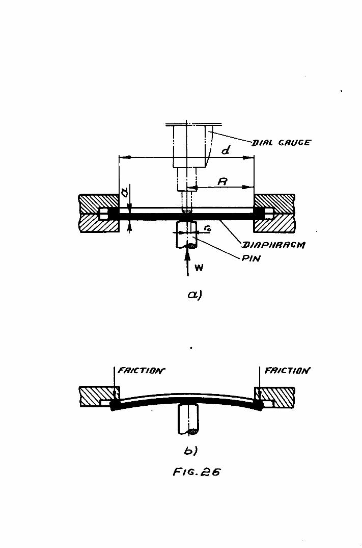
FR/CTID/V"
w
a)
•
b)
FIG. 26
FRICTION

where,
- 49 -
(2 .. 2)
6max
= maximum stress at the centre of the diaphragm plate,
lb/in2
~ = Poisson 's ratio, V = 0.,. w = maximum applied load~ lb
h = a/2
a = thickness of the dianhragm plate, in
01... = r olR
ro = radius of the circular area through which the
load W is transmitted on to the diaphragm plate,
in,. Fig .. 26.
R = effective radius of the diaphragm plate, in t
Fig. 26.
d = effective diameter of the diaphragm plate, in,
Fig. 26
ks = design factor depending on the construction. For
diaphragm plate with edges supported" Fig. 26
.. k is = 0.023
8
" (67) As suggested by Den Hartog t the diaphragm was considered"
as a circular plate with central concentrated load W, Fig. 26 (i.e.
ro is very sma]! compared with d). The maximum deflection of the ...
diaphragm plate was calculated from the following relationship~7 ):
WR2 0.0199 -. in
D

- 50 -
or ~ 2 3 ~ = 0.217 WR IE a t in
where,
S = maximum deflection of the diaphragm plate at the centre,. in
D = stiffness of the diaphragm plate, lb. in
= 0.0916 E a3, lb. in
E = Young's modulus of elasticity, Ib/in2 , E = 30 x 106 lb/in2
For maximum vertical (or horizontal) load of 2000 lb, diaphragm plata
thickness of 0.125 in.,. and effective diaphragm plate radius of 1.5 in,
the maximum deflection was 0.017 in. The maximum stress at the cent~e •
of the diaphragm was 26.5 x 10³ lb/in2
which is much less than the
maximum permissible stress for spring steel ASE-8660 which is 120 x 103
I ' 2 lb 1n •
These spring steel diaphragm plates were hardened in oil at
880oe, tempered at 2000 e and cooled in oil. The Vickers hardness
was Hv = 700. The diaphragm plates were reground to give a smouth
contact surface:
It is significant to mention that different diaphragm plates
(i.e. diaphragm plates with different thickness and effective diameter)
were used, so that to obtain a satisfactory caUibration between the
apnlied load and the deflection. The diaphragm plate dimensions shown
above were considered quite satisfactory for the above purpose.
However the effect of friction between the diaphragm and cover plates;
as shown in Fig. 26b reduces the sensitivity of the dynamometer.
Therefore, any improvement in the construction of the diaphragm plates
leading to a reduction in the friction (between the diaphragm and
cover plates) will be welcomed.

- 51 -
Diaphragm F1aneed Cover Plates:
The flanged cover plate dimensions were calculated according
. (68) b t k' . t . d t' th h t d to Fa1res y a 1ng 1n 0 conS1 era 10n e sear s ress area an
the permissible stress, using the relationship
Jidhs = wF (2 .. 4)
where"
d = diaphragm diameter
h = height for effective shear stress
s = permissible shear stres&
w = maximum load'
F = safety factor
Each cover plate was clamped to the dynamometer body by sioc bolts. By
using a safety factor of 3 and a design stress of 60,000 lb/in2 , the
bolt diameter was i in.
Diaphragm Pine:
Diaphragm pins were made of silver steel. The diameter of
the pin was calculAted from equation (2.4) by taking into~ consideration
the area under shear stress J7d1h Fig. 27, and the annular bearing area.
-- 2 (/1 (d 2 - d1
), 4 2
where, sa = maximum arlowab~e shear stress.
For h = 0.4 in. the pin diameter was = i in.
(2 .. 5)
The diaphragm pins were hardened in oil at 820°C and tempered
at 170°C. The Vicker's hardness Hv = 500. The contact surface of the
pins were polished to reduce the friction.
Tool Holder:
The tool holder was made of gauge steel and designed to hold
tools up to 1 sq .. in. shank. A tool adapter was fitted into the tool
holder to prevent it from rotatins while the tool was under the action


- 52 -
of the vertical and horizontaL components of the cutting force.
The tool holder was hardened in oil at BOOoC, tempered at
150°C, and cooled in oil. The Vickers hardness was Hv = 400.
Roller:
The roller was made of soft steel. The diameter of the
roller was determined from the foLlowing relationshiP(69), taking
into consideration that the load was applied to the middLe of the
roller,
where,
M = pl. max 4
do 3~ 32 k M = t':: m max ~I St
p = maximum load applied to. the roller
1 = distance between the ball bearings
maximum tensile stress
k = safety factor m
(2.6)
For P = 2000 lb.,. St = 12,.000 - 16,.000 Ib/in2 , 1 = 1.5 in., and
k = 1.0 - 1.5, the roller diameter was d = o.B - 1.0 in. m 0
The roller was hardened at BoooC,. tempered at 150°C, and
cooled in oil.
Dynamometer Body Plates:
The thickness o£ the dynamometer body plates was determined
by taking into consideration the diameter of the connecting bolts.
The thickness of the dynamometer body plates was taken 2.5 times
larger than the diameter of the connecting bolts. The plate thick
ness was therefore = 5/8 in. This thickness ensured a safe drilling
of the connecting holes of i in. diameter.
..

- 53 -
2.9.2. Adjustment of the Dynamometer
Befor~ the start of the tests during this work the tool holdeF
was positioned in both vertical and horizontal directions. The tool
holder was moved in the vertical direction by means of the adjustable
skrew (31). Fig. 25. until the dial gauge (15) had just begun to read,
the screw was then covered with plasticine to fix its position. The'
dial gauge reading was made zero. Similarly the tool holder was posit
ioned in the horizontal direction by means of screw (30).
During cutting the vertical component of~hecutting force was
transmitted onto the diaphragm (13) through the pin (8) as the tool
holder (28) moved vertically. The vertical movement of the tool holder
was achieved through its vertical rotation around the link (22). The
deflection of the diaphragm caused by the action of the vertical component
of the cutting force was then recorded by the dial gauge (15).
Similarly the dial gauge (1) recorded the deflection caused by the action
of the horizontal component of the cutting force'.
The use of ball bearings and effective lubrication have
reduced considerably the friction betw~en the contact surfaces of the
dynamometer ..
It is important to mention that the use of the above dynamometer
was limited due to the poor stabiLity of readings at medium and high
cutting speeds when chattering existed. The res~lts obtained from the
dynamometer at ~ow cutting speeds up to 10 m/min.. were quite accurate
for the purpose of this work.
2.9.3 Calibration of the Tool Dynamometer
The calibration of the tool dynamometer for both vertical and
horizontal loads was carried out by static loading on a special lever
device~ The dynamometer was bolted to ~ specially constructed holder,
Fig~ 28, which was rigidly clamped to the base plate (1) by means or
five bolts. The load was applied to a high speed steel tool. (similar'
to those used in the cutting tests) fitted into the tool holder through

~ "'" ~ " ~ ~
~ ~ C\&
\0
~

- 54 -
the pin of the ~ever (2). The pin was made of silver steel, hardened
and tempered to 500 V.P.H. with a rounded Vee shape. The pin was fitted
to the end of the lever so that to apply the load at the same distance
from the tool holder, just as the cutting taol would have done during
the actual cutting operation. The vertica~ and horizontal calibrations
were made in the same manner. At the beginning ~ sma~~ ~oad was applied
to the tool till the dial gauge indicator had just begun to move. This
position of the too~ holder was then fixed and the dial gauge readings
were made zero.. After that the load was applied in increments of 50 kg
and the dial gauge readings were recorded. After a maximum load of
500 kg was applied, the unloading calibration was carried out by reducing
the load in the same increment of 50 kg,- and the dial gauge readings were
also recorded.
The cross-sensitivity of the dynamometer was checked for both
vertical and horizontali loads, and it was found that the vertical and
horizontal calibrations were independent o·f each other'.
The first calibration curves for both vertical and horizonta1
l.oads were not satisfactory. By examining the contact surface of the
diaphragms under the microscope, severa] cracks were found. Then it
was decided to change the heat treatment o'f the diaphragm.. But the
results were still unsatisfactory, now due to the poor sensitivity of
the diaphragms. Finally by reducing the diaphragm thickness, polishing
the contact surfaces of the diaphragms and diaphragm pins and by applying
an ~ffective lubricant (Mobiigrease AA1) to all moving parts of the
dynamometer, a satisfactory linear calibration for both vertical and
horizontal loads was obtained, Figs. 29 and 30.
2 .. 10 STRAIN GAUGE DYNAMGHETER
The strain gauge dynamometer was designed to measure the strain
produced in the cantilever tool holder shank by the action of the
vertical and horizontal components of the cutting force at high and
medium cutting speeds.

I !
I
I " i
"1
-+-- ---- i
! I
, , i L.. _ ~ I
.1-
- ~ ,-. ,
.. - .. + ~ •.. ~-. ~1'
i
. " ,
i I , ""

i I I I -I ! I ,: L .. __ ._L. ... I I'
II I I L
-lo·-I , I .~ . :~ '10 . ::t ~ i~~ ~~C5' ~ ct ~ ~.~.~:,
I f' f I
.•. ,' __ 0," , I
i
I 1
, .... - .. --
! 'i--"
.L
. .1
, 1 t.
I :
I I,
,
i i
. ~ -
"
1
1'-
-+- -~
..
;
,,-! I
'1
,
,.
c::a ,.~
,~ I
... 'j
I
i- :~ . .•• J
.1
'~ ,- ... 1 - ~- . ~ a
I ,'" j I L
". ~

- 55 -
Inaccuracies in the readings of this dynamometer caused by
either a movement in the point of the application of the force, or
temperature effect, or interaction between the vertical and horizontal
components of the cutting force were minimized by a careful cali-
bration of the dynamometer and by using a correct electrical circuit.
2.10.1 Circuit Design
In designing the dynamometer, the Wheatstone Bridge circuit was
found to be the most suitable for measuring the strains produced by the
action of the cutting forces. The position of the strain gauges on th&
cantilever and in the circuit was chosen as shown in Fig. 31a to be the
best from the following points:
1. Increased output voltage from the bridge. The positioning
of the four active strain gauges V1t V2 , V3 t V4 as shown
in Fig. 31b, will. increase the output voltage. This could
be explained by the fact that the strain gauges which are
on the same side of the cantilever, are on the opposite
side of the bridger which means that the electricaL
strains experienced by them will be additive. Under the
action of the vertical component of the cutting force
strain gauges V1 and V3
, Fig. 31b, experienc& tensile
strain, while strain gauges, V2
and V4, compressive
strain of equal magnitude·.
2. N~ cross-sensitivity. The effect of the cross-sensitivity
between -the vertical and horizontal components of the
cutting force was eliminated by the symmetrical positioning
of the strain gauges on the cantilever and by using the
bridge circuit shown in Fig. 31b.
3~ Low temperature sensitivity. Using the circuit shown in
Fig. 31b, the cantilever experienced a uniform change in
the temperature. Consequently there was no change in the
bridge output.

,/ ./
,/
__ H,,_~ L-,,.£--+---'-~ - V2 - - ",7 A---f--:a!=-=~ __ ..-/
1I0RIlONTHL GIUJ6ES
VERTICA L GAUGES
~-- ',.,PUT ------1
INPUT------t

- 56 -
4. ~ffect of radial or thrust forces. Since the cutting
forces were applied a distance from the axis of the
cantilever, a twisting moment was produced. The magnitude
of this twisting moment was small compared with the
bending moments, therefore its effect was considered
to be negligible.
The full electrical circuit is shown in Fig. 32. Power was
supplied to the circuit from a Farnell type H.8.U. power supply unit.
Saunders-Roe foil type strain gauges were chosen to be the most suitable
for the above purpose. Each circuit was balanced so that it would give'
a zero output in the unstrained condition. This was done by changing
the resistance in each arm of the bridge through a Beckman precision
potentiometer. A clamp galvanometer was connected to the circuit with
a switching device to find the balance point of each circuit. After
balancing, the circuits remained undisturbed for a short time before
checking the balance conditions so that to eliminate' any drift
caused by the heating of the strain gauges. All circuit system
components were earthed. The circuit was protected from the- coolant.
and flying ch~ps by a plastic cover.
2.10.2 Dynamometer Cantilever
A special tool, Fig. 33 .. with a cross section of 1t" x 1" was
chosen as bein~ rigid enough for this investigation. The tool type "A"
with carbide tips were obtained from Firth Brown Tools Limited. The
overhang of the tool was taken so that to give a high rigidity and
sufficient space for the mounting of the strain gauges.
2.10.3 Determination of Several Parameters
Using Saunders foil strain gauges of 1" x til x 75 Q and gauge
factor of 2.17, the maximum voltage for safe operation of any of tha
gauges is given by(52).

INPUT (~dJ/lSTR~T )
/ ,---/ / I r-/
I I I I I I I I
.J
0:: w A c:r 8 t.L.l (::t:
~
~-~"" "",\.J
~~ ~~ ~CQ .... '-~ ~
~ ~ 8 ~


- 57 -
V2 = Resistance x 10 x gauge area max
Hence for the above gauge,
v = 13.7 volts max
For the cantilever shown in Fig. 31a, the strain at the gauge centre
is determined as follows:
eH(1.2) = i- b MH/E TH (2.8)
where,
IH = a b3/12
using values a = 1 in.- and b = 1iin .. , we have.,
IH 0.27 in 4-=
and,
= 444 x 10-6 in/in
The change in the resistance is determined from the following
relationships:
A R = R x. F xe
for R = 75Q , F = 2.17 and e = 444 X 10-6 , the change in the resistance:
AR = .0722Q.
For any bridge circuit, having strain gauges of resistance
R1 = R2 = R3 = R4 , wired as used in the dynamometer:
O R2 R4 - R1 R3 u t pu t voltage-=
Input voltage-(R1 + R2 ) (R3
+ RJ
For the above case,
Hence,
O. V.
I.V.-= 0.0722 = 0.000964
75
Output voltage = 13.7 x 0.000964 = 0.0132 V.
So a 1" strain gauge in the above case gives 13.2 mV.
(2.10)

- 58 -
The deflection of the cantilever Fig. 31a is:
(2.11)
For P = 2000 lb., L = 4", E = 30.106 lb/in2 and I = 0.27 in4 ,the'
maximum deflection of the cantilever S = 0.005". max
The natural frequency of the dynamometer is determined
according to Ferberg and Kemler(70 ):
where"
then,
f n = c ~
.E.I.
w L4
c = constant depending on the mode of vibration. For the
fundamenta~ mode c = 0.560.
w = the weight of the beam/unit length = 0.354 lb/in.
g = acceleration due to gravity = 386 in/sec2
E = 30.106 lb/in2 and I = 0.27 in4.
fn = 3540 cycles/sec.
2.10.4 Choice of Galvanometer'
By using galvanometers type SMI/S with (tn
Rd = 250 Qt. Sv = 0.375 mV/cm)
AR.E I = R(R + R ) g g
wheret
= 160, R = 75.Q, g
(2.13)
~R = Change of resistance in each gauge' Q ,
E = E.M.F. of the input V,
R = Resistance of one gauge Q,
R = Galvanometer resistance ~. g .0722 x 12
I = 75(75 + 75) = 77 rnA. g

- 59 -
2.10.5 Maximum Trace Deflection
The maximum trace deflection was determined from the following
relationships:
D = (2.14)
where,
R1 = balancing resistance.Q. ,
Rd = damping resistance of the galvanometer Q,
S. = galvanometer sensitivity mA/cm, J.
V = maximum safe voltage'V. 0
For Vo' = 13.2 mV; Si' = 0.005, R1 = 175 Q and R = 75Q the g
maximum trace deflection D = 10.6 cm. which is large enough to record
low values of cutting forces.
2.11 INSTRUMENTATION
An ultra-viol.et recorder series M .. 1250 was chosen as the beat
instrument to provide a continuous record of the forces. Galvanometers
were selected by taking into consideration the maximum output voltage'
expected from each bridge and the frequency of the force variation ..
Galvanometers type SM1/S with a, 'natural frequency of 160 0/5
were found to be accurate enough to record the change in the cutting
forces.,
For optimum frequency response and damping the galvanometer
must see a resistance of 250Q. That was done by addin~ a resistance
of 150 Q. to the circuit between the bridge and the recorder. The
strain gauge dynamometer and its attachments are shown in Fig. 34.


- 60 -
2.12 CALIBRATION OF THE STRAIN GAUGE DYNAHOMETER
The calibration of the strain gauge dynamometer was carried out
on the same lever device, Fig. 28, which is used for the calibration
of the dial gauge dynamometer. The dynamometer was mounted in a
specially designed toolpost.. The overhang of the dynamometer was
taken as close as possible to the actual overhang used during cutting
tests. The vertical and horizontal calibration of the dynamometer
was carried out in the same manner by applying a static load in
increments of 50 kg through the pin of the lever Fig. 28. After a
maximum load of 600 kg, the unloading was carried out in the sam&
increment of 50 kg. A~ these points for loading and unloading were
recorded and the calibration curves shO\-In in Fig. 35 and 36 were
obtained.
Although the strain gauges were mounted symmetrically on the
dynamometer's shank and the calibration was carried out as carefully
as nossible, there was still a cross-sensitivity between the vertical.
and horizontal loads,. but it was very small.
It is important to mention that one of the main drawbacks of
this cantilever type of dynamometer was that ita reading was highly
affected by any change in the position of the applied forces.
Calibrating the dynamometer at conditions similar to those of the
actual cutting has reduced this effect.
The results obtained from the above dynamometers were quite
reliable.


. I ,. j'j'" . 'j:: ''1'' !' . "'I ". 'j ,'j, ........ , ... / ...... ," .... ! .... I .... ···r .. ... r .. ::.~~ ... ·~-l·· ... j.:-- ... j .. 1 j .. :l.~;. :1.--+-- : .. 11:·~·~L~ < :;; , , Ii I .1 1 . , +1, .. , , .' .. 1 ....... ~
f~' , +- . -, 1 !. . . . : j'" '. r" . +-- 1 .:.:.' • '" •• ex;:
I 1 'I • ':' ,.. ,.". , ..... I· .. ' ~
. '. .. " .. ·1 ....... j ........ f .. ·:--IL .. ~.:+ .. ::.+.~ :.+~:.,+: .. : .. :L.: + . "1"- :~-"::::h: ~.+. :~'": :"; I~ ,I i I . .: .. ,.1 . 1.. 1 ' 1 J. I . ·1· ..... I ~ i • .,,;- -;._. i . -: i···· : :.1' '. I . I t"-- : ~'l . '. , . . T : --\--Nl' ..... -;-.... ··i· .. ·· .... ) ........ ~ ...... :~ .. c. 1-.. : .: ...... +-\: ... '''',' .1 .\ ... :: .... , .. ;: ... :.~+:.' .:.-j--- ·...::t::·· I::l . , " i·" 1 ..... I" I, l' .. j' .,. _ ...
j '., • • t·· . . '. 'I . . . .' .~
1 \' i' .1" .. " .', .. ", 'cj" I . 'I: I . ,~ ,: . " , '. :,':' . . " 'I I I I'· . \L'~ .... ) ....... , .. · .. 1:· .... j.: .. -:oo "'-: '"',:''' .. :j .... :"',' .. ·1 .. -- - ...... ··i-· ... \ ... +--.. J. '
, '~' ,. I' i'" '1' . I' '! ' . 'i . ..... j'" i ., ':. I', T' : :1 r-" -l-'" . . ., .., . . . . ., I ,. , "
:.j. ,.;\ ~ , :.; ... j:: : .. L :; ... : -,:~.'.:.: ~: .. L~i· I] ] J:- ;;·:f·: .. : ... L,- ~t"'~:i':": :~'li.--: .. ~.c: ,.. .; !i'\l:' 1,':1 .',: : ': : ,:j; r~ "R " I·' .:' I. .. '1:.: .,: .c, ":. : ,: ~ i : '\ Ii. ·1 .! .... : ,j '10: . . :.'.:. ~'I:' .' I :..' •.. ,.' ~
,. , '1 -':':". : ' !
• • .j •• " ..... -. -~ ~ "-~ --. .-..... ---- .......
. : ,:: i .
.. , --- f -- • .• ~ +-_
j , I' "1:'
'm:::rH~dlJcJ 9NI::Jtll:J1 ~Hl NO NOIJ.:J37.,:13tZ

- 61 -
CHAPTER 3
3.1 CHIP BREAKING
Swarf disposal has been a problem since machine tools were
developed and up to the present time the metal cutting industry is in
need of sufficient an'd reliable methods of chip breaking. Due to the
appearance of new tool materials such as sintered carbide, ceramics and
cast alloys which allow a high rate of meta~removal, the chip breaking
and chip disposal problems have stimulated extensive investigation. To
obtain maximum efficiency from these high-speed tool materials a
suitable means has to be provided, such as chip-breakers, for curling
and breaking the chips into small pieces so as to remove them from the
vicinity of the tool point, and to facilitate mechanized systems of
chip disposal.
To obtain the desired degree of chip breaking for a particular
cutting condition, two~ facts must be remembered~
1. Chip breaking depends upon the control of chip flow.
2~ Chip flow control is accomplished by bending the chip.
Although the Sheffield area accommodates a fair proportion of
the tool making industry in the United Kingdom, questions of chip
breaking and chip disposal have not commanded the attention they deserve
until recently, when certain of the tool-making firms hav~ started to
develop tools with reliable chipbreakers.
3.2 CUTTING OPERATIONS FROM CHIP BREAKING POINT OF VIEW
The production of continuous chips during turning, boring,
milling, drilling, facing, thread cutting, broaching, tapping and
reaming operations require a solution to the problem of chip breaking.
Chip breaking in all cutting operations depends on the
duration and continuity of the cutting cycle, tool characteristics,
cutting conditions, and the work-piece material.

- 62 -
From the chip breaking point of view the cutting operations
are classified in the foLLowing order:
3.2.1 Turning and Boring
Both turning and boring are processes of metal removal by means
of single pointed tools. A great deal of investigation has been carried
out by Henriksen(71). MUller(72). Bickel(73). Okushima(74). zorev(17).
and several others to establish the effect of different cutting cond-
itions. tool geometries and work-piece materials on the shape, the size~
and the direction of the flow of the chip. As a result of these invest-
igations they concluded that the depth of cut and feed are the main
factors determining the shape and the size of the chips.
EUgene(75) has noticed an increase in the roughness and
irregularity of the chip as the cutting speed or the rake angle is
reduced.
3.2.2 Drilling
In drilling operations the metal removal is achieved by means
of multi-pointed cutting tools (drills)'. Drilling requires not only
the breakage of the chips during cutting but also its removal from the
vicinity of the drill. Crowding of the chips within the drill flutes
may result in breakage of the drill. Unsatisfactory removal of chips
may lead to a wrapping of the chips around the drill, thus obstructing
the flow of the swart.
The main factors affecting the shape and the size of the chips
are the drill design, cutting conditions and work-piece material.
It is essential that the feed and speed should be selected so
that to ensure a satisfactory chip removal and tool life.

- 63 -
3.2.3 Hilling
Although milling is a discontinuous cutting process, chip
breaking is necessary for some types of cutters.
The milling cutter must be designed so that the space between
the cutter teeth will avoid overcrowding of the chips which might
result in the breakage of individua~ teeth.
The angle of the inclination of a single cutting edge is
found(76 ) to have a significant effect on the chip flow. Positive
angle(76) will tend to spiral the chip away from the work, whilst a
negative angle will force the chip to move towards the work.
3.2.4 Broaching
In broaching operations it is essential that the broach should
be designed with sUfficient space for the chips. Otherwise the chips
will tend to pack between the teeth, resulting eventually in failure
of the broach.
Correct cutting fluid will alleviate the forming of a built-up .
edge on the cutter teeth.
Carter(77) has found that the chip's shape and dimensions
depends on the hook angla (angle of the inclination of a single cutting
edge) of the broach (decrease in hook angle tightens the chip coil).
cutting speed and work-piece material.
The use of chip-breakers, increased chip thickness, and
decreased chip width will considerably reduce the cutting forces(78).
3.2.5 Tapping and Reaming
The main problem in tapping is to ensure a sufficient space
for the chips. If chip space is increased by reducing the number of
flutes, decreasing the width of the land or by increasing the hook of
the cuttin~ edges, this may reduce the life of the tap. Spiral-pointed (76) .
taps w1ll push the chips ahead of the tap. t (76)
Helical fluted aps
will tend to direct the chips toward the shank of the tap.

- 64 -
In reaming although the amount of material to be removed is
very small, reaming is a finishing operation and therefore there must
be no overcrowding of the chips in the vicinity of the reamer teeth
which might reduce the quality of the surface finish.
The use of lubricant increases the life o-f the tap and
decreases the build-up of material in reaming which improves the
quality of the surface finish.
Operations like shaping and planing do not require chip breaking,
because of discontinuity of the cutting cycle.
3.3 'dHY USE CHIP - BREAKERS?
In large-batch production when high-output machine tools such
as automatic and semi-automatic lathes are used, reliable methods of
chip breaking are essential so as to eliminate the stoppage time
required for clearing away the swarf from the vicinity of the machines.
Reliable control of the chip breaking and chip flow processes ensures .
a sufficient protection to the operator from the dangers caused by the
flying chips, especially at high cutting speeds. It is also desirable
to have the chip broken into smalL pieces as it leaves the cutting
face of the too], so as to avoid any possible damage to the surface
finish.
Another reason why chip breaking is used is based on consid
eration of the chip disposal process. The efficiency of swart removing
devices such as conveyors is highly dependent on the type and size of
the chips produced. The smaller the size of the chips produced~ the
more effective the chip disrrosa1 system can be. Chips up to two inches
Long are quite satisfactory. However, a further consideration is that
if the swarf is in long ribbons, it may need crushing before it is
dispatched from the works,; but this wou1d be unnecessary if sQlall
chips are produced by the machine tools.

- 65 -
3.4 TYPE3 OF CHIP-BREAKERS
1. Ground Chip-Breakers:
(a) Ground Step Type Chip-Breaker: This consists of a step or
platform ground into the cuttins (rake) face of the tool at
some distance from the cutting edge (Fig. 37). The cutting
edge and rake angle remain unchanged.
(b) Groove Type Chip-Breaker: A groove of some profile is
ground into the cutting face of the tool at a short distanc&
from the cutting edge. This distance must be related to the
feed. The chip-tool contact area and consequently the chip
curvature is controlled by this distance.
Ground chip-breakers are the most commonly used in the machine
tool industry. The main function of the ground chip-breakers is to curl
the chip. The chip will break either as a result of its contact with
the work-piece, the tool box or any other obstacle or as a result of
an increase of stress in the chip as its radius of curvature is
increased. The step type chip-breaker is characterized by its width
and height.
If, in an angular step type chip-breaker, the width of the
chip-breaker is not constant, the chip flow is controlled by the
minimum width of the chip-breaker. If such a chip-breaker has a
negative opening angle (ansle between the chip-breaker and the direction
parallel to the cutting edge fig. 39) with the minimum width at the
rear of the cut, as in Fig. 39, the chip-breaker has a great tendency
to direct the chip against the uncut surface of the workpiece. To
avoid the danger of over-breaking of the chip. Henriksen(71) suggested
that the opening angle should be within minus 5 to minus 8 degrees
for deep cut and minus 8 to minus 15 degrees for shallow cut.


- 66 -
2. Clamped Chip-Breaker:
The clamped chip-breaker is a block of hard materiaL with an
inclined wedge, firmly clamped to the cutting face of the tool and set
at some distance from the cutting edge, Fig. 38,. Clamped chip-breakers
differ significantly from ground chip-breakers in that they can be
taken apart. The position of the chip-breaker can be adjusted and the
height of the chip-breaker is considerably larger than those of the
ground chip-breakers.
The main advantages of the clamped chip-breaker as listed by
Henriksen are:
1. It consumes no carbide material out of the tool blank.
2~ It does not require diamond wheel grinding.
3. Lower tool wear, longer tool life.
4. Simplicity, speed and cheapness of grinding.
5. Adjustability.
The most important factors in c.ontrolling the clamped chip-
breaker's performance are the angle of the inclination~ and the
face width of the chip-breaker w, Fig. (37). However~ with small
inclination angles the chip breaking action becomes soft and increas-
ingly erratic, while for large angles it becomes sharp and violent.
This can be explained by the change in the chip-tool contact pressure,
friction and temperature. During this work, best results were obtained
when JO = 40 to 50 degrees.
It is essential that the chip-breaker wedge does rest firmly
on the cutting face of the tool. Otherwise the sharp edge of the
chip might get caught in between the tool face and the chip-breaker
whicru could lead to overcrowding of the chips which will eventually (711
lead to the breakage of the chip-breaker (Fig. 40).


- 67 -
3. Special Chip-Breakers:
C~ip-breakers of special geometries are used in those cases
where the conventional chip-breakers are not effective. Chip-breakers(69)
shown in Fig. 41a gives a satisfactory chip breaking with hard steels.
A negative land of 0.2 to 0.3 mm on the cutting edge of the tool is
used to break the chip. For ductile materials chip-breakers shown in
Fig. 41 1>-c produce a reliable chip breaking for a fairly wide range
of cutting conditions. Special deflectors such as shown in Fig. 41d
provide a satisfactory chip control.
3.5 CHIP-B'R:~AKER GEOMETRY
Here attention is restricted to chip breaking devices consisting
of an obstruction located on the cutting face of the tool so that ta
produce plastic deflection of the chip into a coil of the desired
radius. Theoretically this radius is found as follows:
(a) For step chip-breaker: From the geometrical relationship
(R - H)2 + L2 = R2 Fig. 37,. it is seen that:
L2 R = i (li + H)
where
R = theoretical bending radius of the chip
L = chip-breaker width
H = chip-breaker height
This formula has previously been obtained by Henriksen(71)
from purely mathematical considerations. The actual bending
radius of the chip is affected not only by the tool geometry
but also by the cutting condition (mainly the feed) and the
cutting material. The bending radius of the chip will be
thoroughly investigated later in this chapter.
(b) For clamped chip-breaker: By assuming that the inclined
face of the chip-breaker \!edge is long enough to ensure-
that the chip becomes tahgcntial to it at some point B ._--.....,..-

42-4 2-2.S'.
42-0.3 4-6
ALL IJIMENSIONS IN MM de _ EFFECTIVE RRK£
I1N&L..£ FOR CHIP BRenJ(ING. ·
a
b
c
d

- 68 -
Fig. 38, and as angles AOC and BAC are equal to 1 ~, we
have'
R L ..1.-W =If = cot -z:~
where,.
R = bending radius of the chip
W = width of the chip-breaker wedge
L = distance from the contact point of the chip
with the chip-breaker to the cutting edge
H = Height of the point of the contact of th~
chip with the chip-breaker'
fl = angle of the inclination of the chip-
breaker wedge
3.6 BREAKING OF THE CHIP
One of the simplest and reliable methods of chip breaking
are those based on changes in the cutting conditions. Although reliable
chip breaking can be obtained by simply changing the cutting conditions,
such as increasing the feed, depth of cut, or reducing the rake angle,
the tool life'will be reduced considerably by these extreme cutting
conditions(17~ 71, 72~ 95).
The methods of widest practical interest are those based on
the use of chip-breakers to accentuate the curl of the chip as it is
formed. The principal types of these chip-breakers have been already
discussed earlier in this chaper. By suggesting that the chip
breaking effectiveness, depends on the chip curl radius, it is found
that under any given operating conditions, a certain radius of the
chip curl is needed for effective chip breaking. The curled chip
has a rough outer surface containing many cracks. The underside of
the chip is smooth and strong under tension. Curling of the chip
merely puts the rough outer side under compression, and unl~ss the'

- 69 -
curlins is very severe, the chip will not break at this stage. To
break the chip it has to be bent so as to put the rough side of the
chip under tension. This is done by straightening the chip,so as
.to give a fracture starting from the rough surface of the chip coil.
Particular ways of straightening the curled chip are:
1. The chip coiL tends to straighten as its end co~es in
contact with the chip-breaker wedge. Fracture occurs
at so~e point not far from the chip-breaker wedge,
Fie~ 42a • The chips may consist of small straight
pieces or chips with a slight curvature.
2. The chip coil t~nds to open as its end strikes some
obstacle such as the work-piece or the tool box,
giving a bending action at the end still in contact
with the tool, resulting in fracture at this point
(Fig. 42 c - d). The chips may consist of half-turns
or possibly one or more turns.
3. The chip coil opens as its end strikes the work-pieca
giving a bending action in the direction of easy chip
breaking at the contact point of the chip with the chip
breaker wedge, Fig. 4~b. As a result fracture occurs
at that point. The chips consist of half-turns or fu]l
turns.
4. The chip is coiled on itself, as, for example, in the
chip formed by a parting tool. As the outer layers of
the chip coil are forced open by the inner layers,
breakage occurs, after a certain number of turns have
been coiled.

a
b
e
• POINT OF CHIP {,ONrHCT • POINT OF CHIP BRERKI..NG

- 70 -
5. When the free end of a helical chip is restrained from
rotating as it comes in contact with an obstacle,
bending is induced near the cutting edge in the direction
of easy breaking. For example t" in a chip-breaker drill,
a close coiled helix is formed, which then impinges on
the side of the hole.
6. In turning, a close-coiled helix may be formed~ which
has a fairly high weight per unit length compared with
the straight chip, Fig. 42e. Whirling of the free end
due to rotation of the helix gives the bending action
near the tool necessary for breaking the chip.
Interrupted feed devices and vibratory cutting methods have
proved effective and reliable to give broken chips for a wide range
of cutting conditions. Various types of chip-breakers such as
deflectors, rollers and other special devices will be described later'
in this chapter. The use of the coolant is often found to promote
effective chip breaking.
3.7 GENERAL VIu:IS OF THJ~ CHIP BREAKING METHODS
Progress in machine design has accentuated the need for
co-operation and mutual understanding between tooL makers and machine
designers. It is essential that the cutting tools should be designed
so that to give a satisfactory chip breaking with a comparatively
high tool life.
Although chip breaking has several advantages (as mentioned
before), their use is strictly limited due to the increased too]
wear caused by the incorrect method of chip breaking. As mentioned
earlier, chip breaking based on changes in the cutting conditions
reduce the tool life, and their use is strictly limited to rough
cutting operations. The chip breaking process is significantly

- 71 -
affected by the feed. For tools without chip-breakers a fine feed
produces a thin stringy chip (called snarling chip) with no tendency
to break. This type of chip is so flexible that it Can wrap itself
around the work-piece, the tool, or any other obstacle on its way.
As the feed is increased the chip becomes more rigid and travels in
almost straight lines. At very high feeds the chip may sometimes
show a tendency to break in roughly regular manner, thereby imposing
a violent variation in the pressure on the tool which leads to an
increased tool wear. The effect of variation in the rake angle is
so small that it can be ignored as long as the rake angle remains
within the conventional limits, as was noticed during this work.
It is observed(71, 95) during cutting that a chip passing
over a straight cutting edge has a natural tendency to flow in a
direction perpendicular to the cutting edge. With a large depth
of cut the effect of the side cutting edge is significant(71), and
the chip flows almost perpendicular to the side cutting edge,
Fig. 43a. With a small depth of cut the effect of the side cutting
edge is considerably reduced and the effect of the nose and the end
cutting edge is strong enough to swing the chip away from the surface
of the work(71), Fig. ~3b. Sinapalnikov and Eikhmans(79) have found
that the cutting edge radius has a considerable effect on the chip
breaking process (through its effect on the cutting forces) when the
chip thickness is small. (This is equivalent to bluntness of the
toal). Albricht(28) has found a similar effect of the cutting edge
radius on the cutting process.
Tests (17) on carbon steel 45 (0.45)~ c) using carbide tipped
tools (T5K12) having a 100 rake angle, 80 clearance,) 100 plan approach

-ti

- 72 -
at a speed of 43-45 m/min. and a feed rate of 0.07 mm/rev e have shown
an incre3.se of 20 to 4cr;~ in the cutting forces as the tool nose radius·
was increased from 12 to 22 mm.
Recently a great deal of research has gone into establishing
the performance of the mechanical chip-breakers. Henriksen(71) has
found that for each cutting material there is a limited range of feed
at which the chip-breaker gives a reliable chip breaking effect. For
feeds below this range the chip-breaker is not effective, while for
feeds above this range the chips are over-broken and extremely small
in size. Although the over-broken chips are preferred from swarf-
removal point of view, the tool wear at high feeds is considerably
(71) F h" t 1 h b f d . increased • ree mac 1n1ng s ee save een oun to perm1t a
(71 ) wide range of feeds •
Chip-breaker performance is also' affected by the depth of
cut, the side cutting edge angle and the cutting speed(80). An
increase in the side cutting edge angle or the cutting speed wil~
decrease the chip thickness. Decrease in the depth of cut influences:
the direction of the chip flow, thus changing the angle of the chip
contact with the chip-breaker which leads to an increase in the
effective radius of the chip cur~.
Nakayama(80) has found that effective chip breaking perform-
ance of the step type chip-breakers depends on the chip curl radius,
the work-piece material and the chip thickness. The effect of the
depth of cut was found to be significant at low cutting speeds.
To ensure a reliable chip breaking Lutov(81) has found that
the main dimensions of the chip-breaker groove should be as follows:
1. The land width (distance "alf Fig. 44-) ~ (0.5 to 0.7)
times the chip thickness or ~ (0.25 to 0.35) times
the contact length.

b d ~I. Fie. 1,.4
F,G. 450.

- 73 -
2. The groove radius within 0.5 to 4.0 mm when the land
~idth is within (0.05 - 0.10 to 0.5 - 0.8)mrn.
3. The groove depth within 0.1 to 0.2 mm.
It f' • t· t· T1" b (82) h d d th As a resu 0_ 1nves 19a 10n c.a anov _as recomnen e e
followine dimensions of the chip-breaker groove to be the best from
the chip breakine point of view, Fig. 44.
Cutting Material Groove Dimensions
Steel b d a c 'rensile Streneth Hardness
kg/mm 2 HB mm mm mm mm
34 and 38 137 and 143 0.1 - 0.15 1.0 7 1.5
42 and 54 170 and 787 0.2 - 0.3 0.8 6 1.0
58 and 61 187 and 197 0.4 - 0.5 0.4 5 0.8
63 207 0.5 - 0.6 0.2 3-4 0.5
Using tools with a shallow chip-breaker groove IgoShi.(83)
has established conditions at which effective control of the chip
breaking process was obtained. Experimental tests(83) on soft steels
using a shallo'" chip-breaker groove-type tool (at a cutting speed
of 70 to 150 m/min., depth of cut of 0.35 to 1.2 mm and feed rate
of 0.5 to 1.1 mm/rev.) have shown that the best chip breaking result
is obtained when:
1. The chip-breaker land width = (feed + 0.2) mm for
feed range within 0.13 to 0.9 mm/rev.
2. The depth of the groove = 0.2 to 0.3 mm.
3. The width of the groove = 1.2 to 2.0 mm and the
groove radius = 1.5 to 2.0 mm.

- 74 -
It was observed(83) duri~s cutting with tools having a
shallow chip breaking groove that the chip deforms immediately and
starts to fracture in the groove, finally bre~king as soon as it
contacts an obstacle.
Vee type(84) chip-breakers, Fig. 45, were satisfactorily
used to curl the chip. Using tools with Vee type chip-breaker
Proskuryakov (84) has found that best chip control is achieved with
tools having the following dimensions:
1. The Vee angle 0 = 150 •
2. The angle of the groove centre axis should be for
tensile strength.
KG ..J 0 6 t ~ 60 mm2 t 1/1 = l.Aa = 0
6"t ~ 60 KG2 t 1/1= eXa = 50 mm
3. For tools cutting at constant feeds and speeds, dimensions
(f) and (b) should preferably be proportional to the
actual chip thickness (t1
)
It is essential to mention that determination of the
tool dimensions in terms of chip thickness is not
desirable due to the difficulties in finding the
correct chip thickness.
Bazhenov(85) has found an increase of about 35 to 6~fo in the
cutting forces as the depth of the groove is increased. The following
relations were established:
\
- 75 -
Jl (;::roove denth) _-1-to 2 0, Rs (feed = R (groove radius 2
R 1 10 and T (depth of cut)="3
Good chip control was obtained by means of carb-o-lock
inserts (inserts with a negative rake land backed up by a high pos-
itive rake), within the feed range of about 0.007 in. per rev. up
to 0.020 in. per rev. Crowding and corrugating which were resulting
in excess heating of the insert, reducing therefore the cutting
edge hardness which leads to a reduction in the tool life, were
observed at feeds above 0.02 in. per rev.
It has been established(86) that the chip breaking methods
based on the use of fine chip breaking grooves is one of the most
effective and economical means of chip control.
A step on the cutting face of tool has the same effect on
the chip breaking control as the groove. SpeciaLgeometry(87) of
the step has sho ... m an increase of about 20 to 30% in the tool life
with a satisfactory chip control. During this work best chip
breaking was obtained when the height of the chip-breaker was within
0.15 up to 2 mm and the chip-breaker distance (distance from the
cutting edge to the step) was within 0.2 up to 3 mm.
The significance of a clamped chip-breaker is that the
position of the chip-breaker block can be adjusted so that it will
give a satisfactory chip breaking over a wide range of cutting
conditions.
The angle of the inclination of!he chip-breaker face (wedge
angle) is found to be one of the main parameters controlling the chip
breaking process. Best chip breaking results were obtained with a
1 'th' 400 to ~oo (95) wedge ang e W1 1n ~ •

- 76 -
(86) A srecial deflector type of clamped chipbreaker (Fig. 46)
with a groove-type tool was successfully used by Proskuryakov to
control the chip breaking process when large steel pires (up to 1 m in
diameter) were machined. Best chip breakine results were obtained when
B = 5 to 6 mm and H = 10 mm for machining steel pipes with a diameter
of 700 to 820 mm at a cutting speed of 132.5 to 151.5 m/min., a feed
rate of 0.8 to 1.1 mm/rev. and depth of cut of 8 to 12 mm using the
followine dimensions of the groove:
The groove radius = 3.5 to 4.0 mm
The groove depth = 0.9 to 1.2 mm
The chipbreaker distance = 0.9 to 1~2 mm
Althoug~ this device is claimed to work satisfactorily for a
wide r~n~e of cutting conditions,. the hand feeding used with this
device suCgpsts that the chip breaking might be affected by the
variability of the feed.
loffe(89) has designed a special device for breaking the chip.
It conRists of a roller clamped to the cutting f~ce of the tool tip.
Under the action of the chip pressure, the roller rotates and forces
the chip to bend. Finally the chip breaks as it comes in contact with
the unmachined part of the work-piece. Although this device is very
simple and gives a satisfactory chip breaking for a wide range of cutting
conditions, the roller must be mounted on the tool tip with a
considerable care to obtain efficient performance. This device has
been modified by Kondratov(90 ) and Kiseler(91) so that to ensure a
good reli~bility and to eliminate the possibility of the chip passing
between the roller and the work-piece. This was done by using a
hiChly ro~ished roller with a close setting to the cutting edge.

H

- 77 -
POlogov(92) has designed a universal clamped chip-breaker
with automatic self adjustable step working on the principle of
balancing between the chip breaking force and the applied spring
force (Fig. 47).
Tests have shown that the chip-breaker with automatic'
setting of the chip-breaker step operates successfully within the
range of cutting conditions commonly used for carbide and ceramic (92)
tools •. It has been established that the distance between the step
and the cutting edge changes in direct proportion to the depth of
cut (similarly the feed) and in inverse proportion to the cutting
speed. The main danger with this design is that the sharp edee of
the chip can get caught between the tool face and the chip-breaker
which will lead to the breakage of the chip-breaker.
Interrupted feed devices and vibratory methods were'
olaimed(93, 94, 97, 98) to provide a reliable chip breaking within
a wide range of cutting conditions. (Interrupted feed devices and,
vibra tory methods will be discussed in detail. later in this chapter).
Tests(95) at high cutting speeds within 200 to 400 f/min.
as well as at low cutting speeds have shown. that the distance' from
the cutting edge to the chip-breaker wall and the angle of the
inclination of the chip-breaker wall for clamped chip-breaker, the
height of the step and the distance of it from the cutting edge for
step type chip-breaker and the radius of the groove, the depth of
it and the width of the chip-breaker land are the most significant
parameters controlling the chip breaking process.


- 78 -
3.8 EFFECT OF COOLANT ON C:!IP BREAKING
The use of coolant in cutting operations is considered to be
significant in promoting effective chip breaking.
It is important to mention that lubrication is essential to
avoid over crowding and corrugation of the chips at the chip-breaker
when the chip-breaker width is smal~(95). The effect of the coolant on the chip-breaker performance has
been widely investigated by Bazhenov(85). Coolant was found to have
a slight effect on the chip size. However, effective lubricant reduces
. (85) the chip S1ze • The significance oftbe coolant in promoting eood
chip breaking can be explained by the fact that quenching of the chip
will help in developing fracture.
It is also significant to mention that using a strong jet of
coolant will prevent the chips from flying, therefore reducing hazards-
to the operator. Coolant is also used to direct the chips towards the
swarf removal units.
3 9 THE EFFECT OF THE GRINDING ON CHIP BREAKING • The chip breaking effectiveness is significantly affected by
the grinding finish of the contact surfaces of the tool and chip-
breaker. For accurately polished tool and chip-breaker faces the
chip floW is conditioned by the chip-breakers geometry. As the tool
starts to wear off the chip flow control becomes mainly dependent on
the roughness of the cutting face of the tool. Opitz(9) has shown
that as the depth of the crater formed on the cutting face of the
tool is increased, the radius of the chip curl drops, and the tendency
towards producing small chips increases. However, excessively small
radius of the chip curl will obstruct the chip flow and lead to a
considerable increase in the cutting forces(9, 17, 71. 95, 101).

- 79 -
Kozacka(96) has found that the chip breaking process is
affected by the direction of the grinding marks on the chip-hreakerts
face, which leads to a change in the cutting forces. If the grinding
marks are parallel to the side cutting edge (i.e. if the chip slides
perpendicular to the marks), then the cuttin3 forces produced are less
than if the marks are at right angles to the cutting edge (i .. e. if the
chip slides along the grooves left by the grinding wheel). However"
this effect disappears if the marks are shallow. For best chip-breaker
performance Kozacka(96) suggests the lapping of the carbide tool tins.
3. 10 CHIP BREAKING BY MEANS OF INTERR1TPTED FEED DEVICES AND
VI3RA~ORY METHODS
Recently the use of interrupted feed devices for different
cutting operations have shown a satisfactory chip breaking performance.
In these devices the breakage of the chip is achieved by a periodicaL
change in the chip thickness, du~ to the discontinuity of the cutting
cycle. Interrupted feed is applied either by electrical or mechanicall
vibration of the cutting tools. The chip breaking effectiveness of
these devices depends mainly on the direction, amplitude and frequency
of the applied vibration. For effective chip breaking the following
requirements must be satisfied.
1. The direction of the vibration should coincide with the
direction of the feed.
2. The amplitude of the vibration must be made as high as
possible.
3. The frequency of the vibration should be between 5 and
120 cycles per second.

- 80 -
The reasons why interrupted feed devices are widely used in
metsl cuttins operations are based on the following advantages:
1. Interrupted feed devices can be applied to different
cutting operations such as turning. boring. milling. etc.
2. The tool life obtained from these devices is longer than
those obtained from a conventional chip-breaker.
3. Interru?ted feed devices ensure a reliab~e chip breaking
for a wide range of materials (including hard materials)
and cutting conditions.
4. Tool vibration enables the coolant to distribute and
penetrate more effectively.
Reduced efficiency of the machine tool as a result of increased
machining time caused by interrupting the feed, is the main drawback of
interrupted feed devices. However. this could be improved by using
high cutting speeds and feeds. It is also significant to mention
that interrupted feed devices are complex and expensive to install,
and that some of these devices produce a poor quality of the surface
finish.
The vibratory turning(93) of the highly ductile metals with
tool vibration of low frequency up to 5 cycles per second and high
amplitude of about 1.5 mm ensure reliable chip breaking within a wide
range of cutting conditions. Chip breaking based on this method(93)
has shown an increase of 50l~ in the tool ~ifet a reduction of up to
65% in the consumed power and a satisfactory surface finish.
Chip breaking methods based on self-exciting vibrations(94)
induced by the cutting process is highly reliable. It is suitable
for use in mass-production conditions when machining components with
a uniform machining allowance and with metals which ensure the
possibility of inducing self-excited vibrations.

- 81 -
Zakh~rov(97) describes a hydraulic interrupted feed device,
whereby the tool is eiven an interrupted ~ovement by means of an
auxiliary hydrauLic system. He found that the chip length can be
accurately predicted and depends mainly on the diameter of the work-
piece. Zakharov suggests a combination of interrupted feed device
and conventional chipbreaker,. for effective chip breaking when
work-piece of large diameters ( 50 mm) are machined~
Several interrupted feed devices are also described by
Koponov(98); Baranov(93), Schnellmann(99), POdugaev(94), Weil~(100),
and others.
3.11 CHIP CURL RADIUS
Chip curl radius is one of the most significant parameters
determining good machinability characteristics, due to the fact that
the chip-tool contact is controlled by the chip curl radius. It is
also significant as it was suggested earlier in this chapter that
the chip curl radius represents the effectiveness of the chip breaking
process ..
The chip curling mechanism has been investigated in detail
by Ernst and Merchant(14l,. Albricht(28). Okoshima~ Hoshi and
(101) . (71) (80) (102) (103) Fujinawa ,Hellr~ksen ,Nakayama ,Ponkeshe , Lamm ,
. ( 104) ( 105 ) Cook. Jhaverl. and Nayak t Dawe and Rubenstein and many others.
As a result of these investigations, different sugeestions were made
to explain why the chip curls. Ernst and Herchant(.14) were first to
suggest that the chip curling is a result of greater extension in the
underside of the chip compared with the upper side as a result of
variation in the rate of deformation across the shear plane. Henriksen(17)
by considering the chip as a cantilever beam under the action of the
chip-tool contact pressure, susgests that the chip bends as a result

- 82 -
of non-uniformity of the chip-tool contact pressure. Albricht(28)
suggested that the chip curls as a result of non-collinearity between
the lines of action of the resultant cutting force acting on the work-
piece and the cutting tool, which leads to the appearance of a bending
moment which forces the chip to curl. Similar suggestion was made(103)
by taking into consideration the thermal strains produced in the chip
" P k h (102)' t th t "f"t f th h during coo11ng~ on s e sugges s a non-un1 orm1 y 0 e sear
zone width, leads to a different degree of strain hardening across the
chip width. Since the chip is unstressed after it leaves the cutting
face of the tool, there must be a stress-relieving zone adjacent to
the shear zone, resulting in non-uniform residual shear strain across
the width of the chip and hence rotation. Cook, Jhaveri and Nayak(104)
have found that when materials which do not strain-harden (such as lead)
were cut at low cutting speeds and at room temperature the chips do not
curl, while the chips curl when strain-hardening materials (such as
steel, aluminium, copper) were cut under the same identical conditions.
From this they concluded that the chip curls due mainly to the strain-
hardening." They also concluded that the chip breakage is strongly
dependent upon the natural curling tendencies of a material" which vary
from one material t~ another. Conclusions similar to those of
Albricht were arrived at by Dawe and Rubestein(105). They suggested
,
- that the phenomenon of chip curl can be attributed, basically to non-
collinearity of the resultant cutting force acting on the work-piece
and the resultant c~tting force acting on the chip~ All these suggestions
are based on experimental evidence and therefore they are equally plausible.
However, some of these suggestions are in better agreement with theo-
retical explanations of the n~ture of the chip curvature than the
others.

- 83 -
All these sugeestions which were made are to explain the chip
curling mechanism without the use of a chipbreaker. However, the
situation is changed when chipbreakers are used and the chip curl radius
will mainly depend on the geometry of the chipbreaker. It is signi-
ficant to mention that these effects which were suggested earlier
still exist and will have a secondary effect.
The theoretical chip curl radius was first determined by
Henriksen from purely geometrical considerations. From the geometrical
relationships between the chipbreaker's width and height and the chip
curl radius, Henriksen has developed the formula described earlier in
this chapter for determining the theoretical chip curl radius. However,
this formula does not take into consideration the effect of the cutting
conditions on the chip curl radius. By taking into consideration the
effect of cutting conditions, tool characteristics and cutting
material, Okushima(101) has analysed the mechanism of chip curling and
found a theoretical expression for the .chip curl radius in terms of
the above mentioned factors. The writer considers that ·the theoretical
analysis of chip curling mechanism suggested by Okushima is fairly
representative if the effect of the chip-tool contact on the chip
curl radius bas also been taken into consideration. Therefore~ it
was decided to show in detail the theoretical analysis of chip curling
mechanism originated by Okushima by taking into consideration the fact
that the chip starts curling away from the face of the tool as soon
as it reaches the end of the chip-tool contact region. This means
that the effective chipbreaker width must be taken as the distance
from the end point of the chip-tool contact to the chipbreaker heel
(i.e~ distance L-f, Fig. 48), instead of the whole chipbreaker width
(i.e~ the distance from the cutting edge to the chipbreaker heel,L,
Fig. 48) •.

FIG. 48
--¥---~-E.
K fiG. 49
L-+-~el------ x :JII:.
FIG. 50
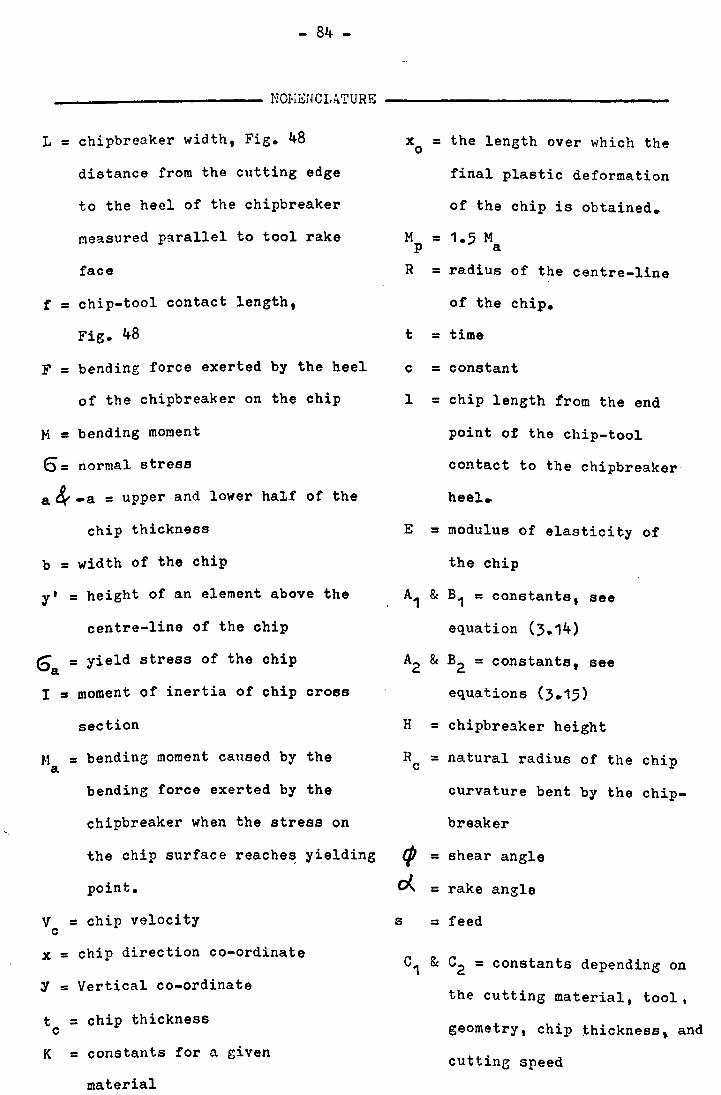
- 84 -
____________ NOl·lEHCLA.TURE -----------------
L = chipbreaker width, Fig. 48
distance from the cutting edge
to the heel of the chipbreaker
measured p~rallel to tool rake
face
f = chip-tool contact length,
Fig. 48
F = bending force exerted by the heel
of the chipbreaker on the chip
M = bending moment
E)= normal stress
a ~ -a = upper and lower half of the
chip thickness
b = width of the chip
y' = height of an element above the
centre-line of the chip
E) = yield stress of the chip a
I = moment of inertia of chip cross
section
J.1 = bending moment caused by the a
bending force exerted by the
chipbreaker when the stress on
the chip surface reache~ yielding
point.
V = chip velocity c
x = chip direction co-ordinate
y = Vertical co-ordinate
t = chip thickness c
K = constants for a given
material
x = the length over which the o
final plastic deformation
of the chip is obtained.
M = 1.5 M P a
R = radius of the centre-line
of the chip.
t = time
c = constant
1 = chip length from the end
point of the chip-tooL
contact to the chipbreaker
heel.
E = modulus of elasticity of
the chip
A1 & B1 = constants, see
equation (3.14)
A2 & B2 = constants, see
equations (3.15)
H = chipbreaker height
HC = natural radius of the chip
curvature bent by the chip-
breaker
shear angle
rake angle
s = feed
C1 & C2 = constants depending on
the cutting material, tool,
geometry, chip thickness, and
cutting speed

- 85 -
The chip curl radius is calculated by applying the theory
of plasticity under the following assumptions:
1. The material being cut has no work hardening~ Fig. 49.
2~ The chip flows straight along the cutting face of the tool
for a tool without a chipbreaker.
3. The cross section of the chip which wa:s plane before bending
remains plane after bending, and the neutral layer is always
at the middle of the chip thickness.
4. The heel of the chipbreaker exerts a bending force F on
the chip, Fig. 48. The bending moment produced by this
bending force is assumed to be linearly distributed along
the chip length, Fig. 50.
5. By taking into consideration the time rate, and by considering
the chip as a beam of rectangular section. the normal stress
at any arbitrary point in a cross section and the bending
moment at the same section can be represented by the following
equation:
M = b Sa. 6 Y' dy' -a
At yielding point, the bending moment is calculated from
equation (3.3) by taking
M a =
6 = 6 (y'la) a
(8. 2 b J 6/a y'
-a. dy' = = 6 Iia a
\/hen the whole cross section is under plastic deformation"
the bending moment
M = 6 5.2 y' dy' a -;I.
is:
= = .l. 6 I/a 2 a = 1, 5M a (3.6)

- 86 -
~hen the bending moment M is more than 1,5 M , it is assumed a
that the bending deformation increases with the time. However, the
duration of the time for the chip flDwing at a constant velocity V c
under such a bending action is short. Therefore, the rate of the
deformation is significant in this case. Since the bending moment
along the chip length (1) is maximum at the end point o~ the chip-
tool contact which is at a distance f from the cutting edge, the
time rate of deformation will be maximum at the same point. As the
chip leaves the end point of the chip-tool contact, the bending
mcment decreases, and therefore decreasing the rate of the deformation.
The point 1,5 M corresponds to the end of plastic deformation. It a
means that the chip has had sufficient pllastic deformation within
x = x and as the bending moment value drops below 1r5 M the chip 0. a
will undergo no further plastic deformation~ Therefore, as lcng
as M '-1,5 Ma' i.e. x> xc' the deformation cf the chip conforms to.
the theory of elasticity.
Assuming that the time rate of the deformation is prop-
crtional to. M - 1,.5 M as long as M>1,5 M , and writing 1,5 M = M , a ~ a p
we have d( 1!R)
dt = C (M - M ) , (0 < x <. x )
p o·
Frem assumptien (4)
M =
Hence. d(1!R)
dt
1 - x
1 - .x o
= C (
M p
1
1
- x
- x
x - 1 ) M C H 0 = p P 1 -
0.
(O(x(.x) 0
- x , x
0

- 87 -
Since the chip flows perpendicular to the cutting edge,
v = dx/dt c
Hence equation (3.9) becomes,
d( 1/R)
dx =
C M P
v c
Integrating equation (3~11) with 1/R = 0 at x = 0,
1 If =
C M --....;p_(x x V (1 _ x )0
c 0
2 x
2 ) t (0 (x(x )
o
According to assumption (5) when x)xo t the chip conforms to
the theory of elasticity. As the bending moment decreases, the chip
curvature reduces by an amount which at any distance x is equal to
N x - x P o.' ----
EI 1 - x o
So curvature at points (x)x ) 0)
2 Mp x M x - x
1 ,.. 0 --E.. 0 v ..... =- -
R Vc 1 - x 2 EI L- xo 0
is
(x ~x~l) 0.'
(3 .. 1J)
1 d2
Now we have two equations (3.12) and (3 .. 13) giving curvature "R=.!L.f dx
By integrating
dy
dx
C M p
equation (3.12) we have:
x2 x3 (x - --+ A
1) =
V (1 - x ) c 0
C M P
y =-~---V (1 - x ) c 0
o 2 6 ) ) ) ) ) ) ) )
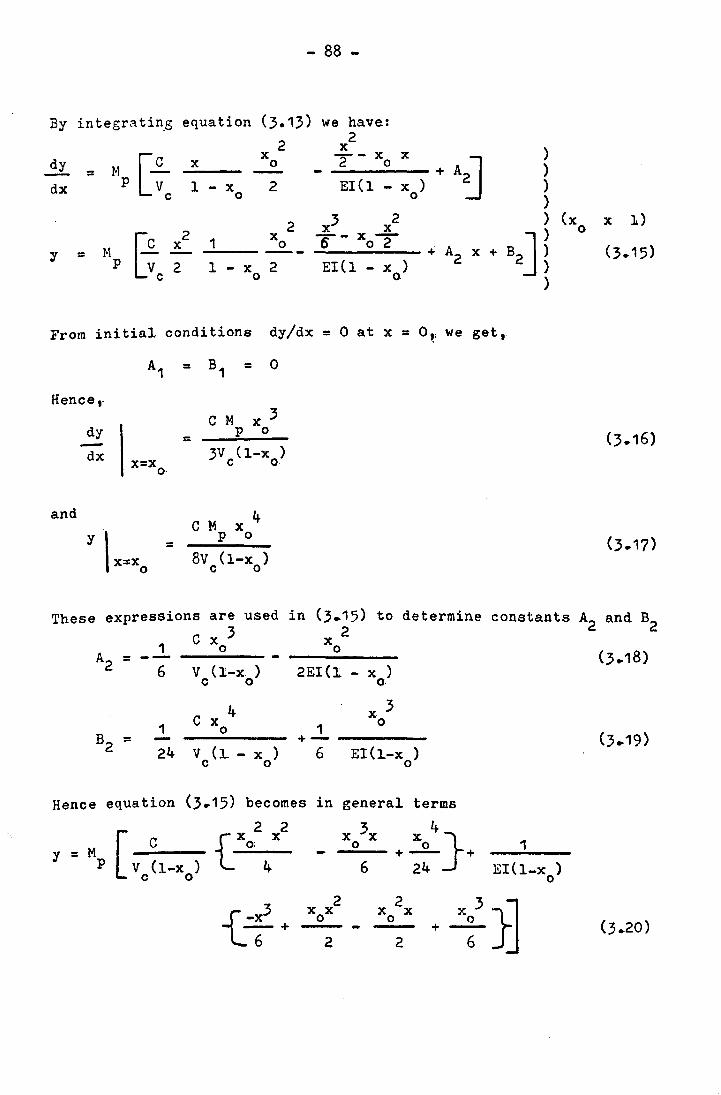
- 88 -
By integra tin.S equation (3.13) we have:
2 2 x
M[-£-x -- x x
+A~ dy x 0 2 0 =
dx P V 1 - x 2 EI(I - x ) c 0 0
2 x3 2 2 x
[~c 1 Xo --x-}i
x 602 + A2 x + y = P 2 1 - x 2 EI(I - x ) 0 o·
From initial conditions dy/dx = 0 at x = Or we get,
Hence ,.
and
dy
dx x=x o
=
= C M x 3
p 0
3V (l-x ) c 0
4 C M x
P 0
8v (l-x ) c 0
) ) ) ) ) (x x 1)
B2] l 0
(3.15)
)
These expressions are used in (3.15) to determine constants A2 and B2 C x 3 2
1 --6
1 -24
o Xo --...;...---V (l-x )
c 0
C x 4 o
v (~ - x ) C 0
2EI(1 - x ) o·
1 x 3
o +------
6 EI(~-x ) o
Hence equation (3.15) becomes in
2 2 {Xo; 4
x
general terms
[
C Y = M
P V (I-x ) c 0
x 3x 4} o + Xo +
6 24
{
_X3 -+
6 2 2
1
EI(l-x ) o

- 89 -
As the conditions for chip contact with the chipbreaker is y = H at
x = I, we have
M C x2
[t-M 13
p 0 12
x ..L(0)2J - p G H = t (10
) + 'b-V (l-x )
24 1 El(l-x ) c 0 0
or e
M M C Xo [:2 - -~)~ p 24- p =
(Xo/l)2 -(1
V (l-x ) G - 4(xo/ l ) + GEl c 0
But as N p = 1,5 Ma' hence equation (3.22) becomes:
2 MpC Xo
V (l-x ) c 0
=
From equation 0.23), (3.20), (3.13) and (3.5) when x=l or
x ...1. (--2..) 2 1
1 = L-f, the natural radius of the chip curvature R bent by the c
chipbreaker is,
M C x 2 N 1 + 0 p
1r = -2(1-xo
) El c c
= ___ 1_~_[:2
x x 2 G-4(L~f)+~L~f)
1 - x 0 = 1 - x
0
_H_p_ {12 _ (L_f)2
x
x 12(~) +
L-f 4 5( xo)216'a 1]
, L-f J E ~
(3.24)
Now it is assumed that the ratio L-~ is determined by the chip
velocity, chip-tool contact length, work material and tool geometry.
Therefore, the expressions

- 90 -
are considered to be determined by the same factors. 6 and E are a
properties of the material, and they vary with the temperature of the
chip. Consequently (6a/ E ) is a function of cutting velocity as this
affects the temperature of the chip.
Since a is half of the chip thickness and is given in terms
of shear plane anele by
a = Cos(t/? -~)
2Sin4>
the expression (3~25) reduces to:
1
R c
H C .1.. (L _ f)2 - 2 S
(106) But according to Creveling, Jordan and Thomsen , the chip tool
contact length is represented in terms of chip thickness as follows:
f = K t c
They(106) also found that for steel, K = 1 and although this is probably
not true for all conditions and materials it seem~ unlikely that the
value of K will vary considerably and that for the present purpose it
would seem reasonable to assume that
fIt = 1 c
Hence equation (3.25) becomes,
H 1
- C -2 S
Equation (3.26) will now allow the n~tural radius of curvature of chips
to be estimated for a chipbreaker of given dimensions and will take
into consideration the effect of the chip-tooll contact length.
However, there seem to be severe limitations in the sienificance of
this analytical result. It indicates that at a particular tool and
cutting conditions, radius R should vary with Land H as predicted c

- 91 -
by expression, (3.26). Ho,~ever" any change in tool geometry or cutting
conditions will give different C1 and C2 •
During this work a series of tests were carried out so that
to establish the values of the constants C1 and C2 in equation (3.26).
The values of C1 and C2 were determined, by measuring the chip curl
radius and chip thickness for a large number of chips. As a result
of these measurements the values of C1 and C2 'were established for
each particular tool and cutting conditions~ For steel EN1A and
aluminium alloy HE30WP using carbide tipped and high speed tools ~f
150 rake angle at a cutting speed of 50 to 100 m/min, a feed range of
0.05 to 0.50 mm/rev. and with 3 and 6 mrn depth of cut and with coolant ,.
8 -2 the values of C1 and C2 were found to be 1. ; 1.52 and 2.2 x 10 ; J.Ox
respectively. The values of C1 and C2 obtained for steel EN1A differ
. (101) noticeably from those obtained by Okush~ma for carbon steen
(0.4%C) cut at conditions similar to those mentioned above for steell
EN1A (accordine to Okushima C1 = 4~4 and C2 = 1.2 x 10⁻² ). This is
expected to be so due to the fact that the values of C1 and C2
obtained from the experimental tests carried out during this work,
do take into account the effect of the chip-tool contact length as
well as the effect of the parameters mentioned by Okushima.
In appendix I the author suggests a different theoretical
approach to the mechanism of chip curling for both ground step and
clamped chipbreakers.
Trim and Boothroyd(107) have developed a theoretical
expression for the chip curl radius based on the Henriksen formula
for chip curl radius r by taking into consideration the effect of
the chip-tool contact length.

R
(L _ t )2 c =-----
2H
- 92 -
H +-
2
This equation allows to determine the radius of the curvature of
chips obtained from a chipbreaker of given dimensions and will take
into account the effects of any changes in feed rate or undeformed
chip thickness.
3.12 CHIPBREAKING EFFECTIVENESS
In this investigation, the chipbreaking process is analysed
on the basis that the experimentally measured chip curl radius agrees
with the theoretical and that for a given material and feed, the
theoretical radius of the chip curl expresses the effectiveness of
chipbreaking. For the sake of simplicity, it is also suggested that
the chip curl radius should be some multiple of chip thickness.
Since it is difficult to have an accurate measurement of the chip
thickness and for a convenient plotting of the results it was decided
to represent the chip curl. radius in terms of feed(S) per revolution.
that is the uncut chip thickness. Figs. 51, 52~ 53, 54 show some of
the experimental results obtained by Henriksen(71), Okushima l1Q1 )
and this recent work. Figs. 53 and 54 were plotted as follows:
The chip curl radius was measured for many chips obtained with different
chipbreaker proportions and feed at the conditions mentioned on each
of Figs. 53 and 54. The chips state unbroken. broken (half turn,
one turn or more with chip length over 5 mm), over broken (half turn
or less with chip length less than 5 mm) was registered. All these
results were ~otted. After plotting a fair amount of measurements,
three lines were drawn. The first line (A) Figs. 53-54 was drawn
sO that to separate the points corresponding to unbroken chips from
those corresponding to broken chips. The second line (C) separates
the over broken and·built-up chips from those of effectively broken
ones. Chips were considered effectively broken when their length

Lj
S 1.&1
~ ~ ~I
q kl ~
FiG.Sl BR£nI!INC -::J>£GREE. 1/,/ FI€Lfl710N TO CIIIP CURL RI1DIUS /lIVD F££7) 4CCORDINt;; TO HENREIs'SEN
o.sl'_' ,\' I14NR€HS~N
I : __ L __ ~ ___ -t---,: -- w t-- :---:- .. ~ l--i. -p:
'~!'!" I . II I 1 ] I II · t' nle --.-- Q:
I'. I IUJ 1\9 .~ :~
i~
~
-+ ____ :- ' ~ ..,J
t:~~-t-~:t~~;--:---r-::-:;--:-~-t-:~"': ---:- - r---- 1- -- -- - --1- ------r :;'t---:-:---:--;--T-:---:t--- ----;-! ; ~1. ,I: I : i I l'l:l ~---l--- -! - - I ' ~ : 1 ' li'- --~-- '--r:--J -' 1 . C) ~ : . i, ~ ~-!--'7--- I :""'I
o 2. 4 6
THEORETICAL B
CHIP ~o
CURL
: _ l ::-r--: !, ! --1---i-- " .. I'; .+ . - -1 ! I : !
I
'6 20 .?4
_ mnL
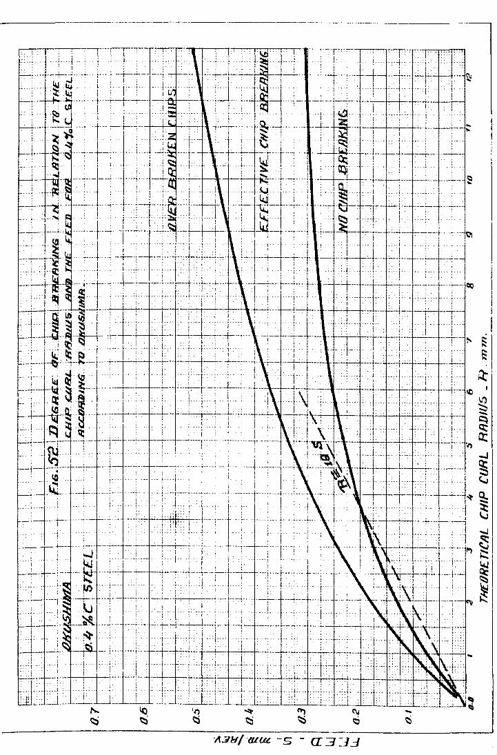
1.. t
I--~-t__+--. -- .---+-- .-
, . L .
.. . 1 .
--------------_.---------,
I • ~ ! . t .. : ~ - :._. L ; :. .
I -:. 1 . --L.: .. I
'''"' ~ <"\j ~ ~ ~
-+--. 00 i
.- "" .
i -r-... j ...
j
T t-. ~ ~
I
~
-J
.. I .. ~ ~
S: ~
i .. ....,j
.-+~. ,., ~I ! ~
~ ~. "

.••. j. \ -~:--;--·-·;·-··-·!-·--C--T··-~. T-' : . \ . \ ...... \. : :1 : .. \ .~ .. \ ,,:" .! .: ! :-T--T--:-T ! .. -;-.-.. -i - ... :----~: ~.--~
t:-;·~· i'-' fiG :~cHiP~_sHcim~_.l£Eli£i.litvhi4s.s·l-···;:JqRtA~-iJNWaiiM~._~ LLQ£JHi3ti~_~.l_~ ..... : ._ .. i \: .. ; .:. ~sJIi& \ A lilRDUNp~.~.Tltf~··r:Hlp. E1R4AHf.:R.\-: \ ... ~. ,. ;. ~~ __ -l ____ ~_._. ___ .. ~ ________ ~_ ---~---~----·----~---·---~--·---~:---t--+-;--+-----+-·-~~-r-~-~----~--'-----~ ------.--~--~----:-.-.---
LJ.~i--·:ALUMrINlllM-~ALLOY~(3Q!WP+=-_:·-·~~\ .. j-.--~- .... :
~... :'" : .. ~UTTING~" ;SPE:£D .. \ w?T4 ·1{j~N!/Ml'u.·:-1 "TllVEB.BRflxEN .. ,. r-··---~·-·--'··-·RAKr_,s.. NGL'E . : .:. !J j lj . t~ . :'. AN~' BUILT-UP. CHIP' '-'_. . __ :
i r ....... . DEPTH'OF CUT:" :"':1'-'T---:'-~"6~OMM ;-.. :; .. :: EGJ01A' ' , v . .; .. : I a 6 . ,.. .: I ~------l.----_~ , I -- -. --- . / y----- ,-"-·--eV --.- -t----- --! " t--:-- ;"-' "'-'--WITH . qOL'!-NT:--~ :; ;.~ _ t.. .L .. : ..; ... ;... :.., . . ; :.:.;. ~ ... C
---' ......... --~----~---- --~-~.-----_._.. .--:.---._. -.~ _______ __i_----. ----..-:::
~ O.Siu;~-~ T ._ .. ·'uun
, n,_nu
n ---~--'i .. ~~. r i .-~- UU_ ~ ~_~L~un~~ \J~ i_u-" r·· '. . . ..- .... -.- . --.... -- .. _-_._----,-" ~ . •.. d ~I r·-· ire-tu-nnTn, · .•. ..• . ... EFFTCTlV£LY .... -7Y.-.~-: ... "
0.·--.. ···:..· ...... -:..- .... : ......... - ... _.,--...... , . -:---.. -- ... : ... ·· .. -··---· .. ·· .. r·-·· . : .. --.. ....... B ROlL EN CHIp· . " • i .: . . . . 11 , . . .
U1 i i .' . . ____ ...... _ .. _ .L.-... R£G10N. ., __ .. ! f--- '--c' .. _ ...... - .. _ .•. -•.. -: .... -~ .. ----:-.-.-- .:-.- .-. /
I ! . . , . : • ..-/' . _ Qll1.3I~' .... : ..... . .. un c- T ... ~ .. _'_u_; ,·-: .. -T-~/-4n- ___ '_'- .'. • . 7J?J=. ~! t~~ .. u,_e_ u
_. ! ...• , ~~-;/: <i- L • I! Rllk£N " tllJP '1J(J7J . A
I a~~I=-_u-u~ .. ~-~~~~-- .. -~ .~-:.n~-:~= ... ::.~~ .. _D~:~~.C~ .. ~~k~~-~-D-~-~-~.-_J-.~-t~~;~;~. ~:=~--o,t~T-----~·""·~···--?~--."-··-···----··-· . ~
B
~- ~--~ ~ ----~---.: .. ---- -- -~. --I f . : f-
_ .. -.---. - .... ---.
-·-·---4-----'--~' __ ............L.. 6--····-.....:--'-----8-----.....:.----'--- -.. - --10 .- ... -.-.-- -- --~ --:..-'2--.. -...: CHIP CURL RADIUS - R - MM. ,
~ . _____________ .. ___ . ___ .~ _______ .___ _ __, ____ . ____ ._~ ___________ ---i
L......:....--!._. __ . .:._ 2.

~~~\ ... : .\:_: ... ~~- :···~-!-:--~·r~\-:c··:. \~'~--:--:-::-r--':-"""T""-=~=c--r~'--"--~-
. ;'. Fi~5!tC1J;p~~ii8iA.HiN.CLJilfiFu ~:-T~-;--c---r-~' L..l_=\ •. "i_~...: ___ ~_ ~·:"--1: ;-LJ ""\ .1 .... 1- .1·lc~r~-: i'~il·~-1-~X·l ... I : ;-__ -+-_~ .. S.rE.EL ~~.# A :. ,: . . 1'" ...... .... 'r .. - t· -.. .'. u I : I ' . ~. ~_ . tIt t, . I 1 1" ..• -t . " ., ' ".. ' , ., , '" ' , ,"., .. -, .
f."" ~~~~'t-; ...••... ~TI1l\lt-'--~ii;.I:!iJ· ~J .. :j-l-- !LlNDO~R-JIBLJl.liREN, : . -:-,i . I' .. : .. : - . nAK£ ANGLE J .. l ., . . 150 , . T.' t . l 'p 7 ~f: IJP.,CHlP.._ ,-,,-
Q6 ~.~-.-; .. u_+- DW' £,:yuTHC'" (J£.CfLL_ ' !. ~ "··MM·" T "-1-1+ .... ! R'F-GION, .. -!. c.,.C I' . IL dOLANT' ' ... i '. L _ ; _! I': -c--.. ·t---'H+. - •. --.~-- ': j:;;;';';": ~i'" ....-"j
> I i.. .T···-·-·'·- _ ..... -. _~ __ .._ .. L. __ ~. ___ ;L! __ -L_+-c .;"- +-,-;-.; -' r . d .. +c
-
i 1ij I 0 5" . . .,... ....' ,.,.! ,-~r ...., , , ~, .' -... -+-.-.' . • • ,-',._. ' ' " , . ... ' , . ,'" ...... . __ , ._..,_ -' , " " ,'- , .' o..t::r. . , 1"! ::j .• -! . " '. . ' .• ,.--r-.. -;-;-·· J. . fu. . I. ,---+.-~.---:.-.! : ~--~-. i - ~. -~ ~I; r~T-~l---"l-'-":-"'-u,;---~-,-~,-':_u_: _t-._~+_+__: _:.u~_: __ 1 f:FFB:C71vn'Y"'-1 .~. i--'1
0 J ~._~~ __ ;: : ~';'. : ;.: .. :. ..; .. c,: :. +:. . B7fO"'-RE~l\t-t?i'H1P .-~-.~~-' : ,~, . • _. 'r' ' ' r' I V ,f".., ..' U11 f..:.;. ..- _ .. -;----~····T--·-~--·-i--; t-·? R EGIi;JN Li .., ' ; -. ,B
" L_,,_.c ___ !-. ,_ _ .. ," . '- /-,; , o?I?fC'1~ ql I ... l' ",--i-- - • ~i-c~-~ /04. -- BROKEN VV?Ji' .. A
L.JI O.3r--- ~-~-" ....... --- '-~"::"i-" .! ..•. L.1/!}..:;;;" , .. "~=H~_~_ .. ~n.A /)' .. ,'"
I {I.e ~-.-i~- . ' --';--c;- ING R E GI ON ' .../: I ' ' I ., _.
[-r-.... ' -~-, d_ - .. .m ~ !:. ,+m .. '__ ~.
0. t t . : ., . ../ .-; ,
· ~.L;~- .• ~~---.-~-~-;--~-- : --------T .. +---~--,~: .-r---
L...:....-.i .--.---... ----- '-2 --------·.!.---~---4--'-- ." 6 --"B-, . ,
. ~. ___ . . _-'-_..l... __ ' ___ . _'---..l
10 I;J
___ . ___ . __ ____ 1:;/11 P C U ~ L ____ RAD I U? __ ::: .~=- "!! M

- 93 -
was not more than 50 mm. In order to separate the effectively broken
chips from th0se half broken a third line (B) was drawn~ The
relationship between the chip curl radius and the feed defining a line
of equal chipbreaking effectiveness appears to be parabolic rather
than linear. This could be explained by taking into consideration
the fact that the strength of the chip does not increase with the
thickness in the manner of a homogeneous beam, because a thicker chip
will contain deeper craCKS on its top surface, with a relatively
thinner zone of secondary shear on its underside. It is also signi-
ficant that the tool vibration increases with an increase in the feed.
This will tend to deepen the fissures in the chip and the chip will
tend to break due to chattering of the tool~ However, it is difficult
to explain in a completely satisfactory way the causes leading to the
parabolic shape of these chipbreaking boundary curves.
In each of the Figs. (51,. 52,.53, 54) a linear dotted curve is
shown for a particular cutting m~terial and a limited range of feeds.
All the points on these lines correspond to effectively broken chips.
The dotted lines represent a linear relationship between the chip curl
radius R and the feed S.. On the basis that the chips obtained at the c R
chipbreaker geometries corresponding to the points on the line sr were R
effectively broken, the factor S c was,: therefore, considered to R
represent the chipbreaking effectiveness.. However,. the factor S c
will vary with a variation in the cutting conditions, and in particular R
for high cutting speeds the factor SC wil~ be smaller than those for
low cutting speeds. That is because the chipbreaking becomes more
difficult at high cutting speeds(95).
According t~ Henriksen, Fig. 51~ two zones of chipbreaking ar~
recognised~ The first zone covers a usable range of feed at which a
reliable chipbreaking is obtained and called the usable range.. Best

- 94 -
chipbreaking results are obtained within the preferred range. The
second zone covers the feeds below and above this range. For feeds below
this range the chip is not broken and for feeds above this range the
chips are overbroken and extremely small in size~ Both the unbroken
and overbroken chips are not recommended due to the chip disposal
problem and reduced tool life respectively. For best chipbreaking R
effectiveness the factor~ for free cutting steels at cutting speeds
of 50
equal
to 150 m/min~ and a depth of cut of 2 to 6 mm, was found to be R
c to - = 30. S
Okushima has carried out a similar experiment and found that
best chipbreaking results for carbon steel (0.4%c) at a depth of cut R
of 3 mm and cutting speed of 50 to 200 m/min., was obtained when SC
= 18, Fig •. 52.
In this investigation the chipbreaking effectiveness was
fully studied. Different materials such as aluminium alloys,copper.
high,. medium and low carbon steels and stainless steel were tested
under different cutting conditions using different shapes of the
cutting tools and chipbreakers, dry and with coolant. Some of the
experimental results is shown in Fig~ 53 and 54. It was the aim of
this investigation to find a reliable parameter for controlling the
chipbreaking process. Experimental evidence suggests that the R
factor SC more or less represents the chipbreaking effectiveness.
According to the experimental results shown in Fig. 53, the R c factor s- = 25 was found to characterise an effective chipbreaking
when cutting aluminium alloys HE30WP at a speed of up to 10 m/min.
using a ground chipbreaker with 150
cutting speeds up to 120 m/min. the
rake angle and coolant.. At hieh R
c factor S was found to be within
18 to 20. Accordingly the experimental results obtained when
. machining aluminium alloys at cutting sIreeds up to 120 m/min., suggest

- 95 -
R that best chipbreakine results is obtained when SC = 18 to 25. In
Fig. 53 four regions are recognised. The first region covers the no
chipbreaking ranee~ where a continuous chip is produced at very low
feed. It is not recommended to work within this range of feed due to
the disadvantages accompanied with the appearance of continuous chips.
The second resion is the broken chips range. This range of feeds
produce chips half broken and half unbroken, and for good chip disposal
performance, it is preferred not to work within this ranee of feeds.
The third region covers the effectively broken chips. The chips are
of small size and very conveni~nt for disposal. The tool life and
surface finish are satisfactory. The fourth rezion covers the
overbroken chips. It is not recommended to work with this range of
feed due to the increased tool wear at high feeds.
Similar results were obtained for steel EN1A. Fig. 54 shows
the experimental results obtained when machining steel EN1A at cutting
speed up to 120 m/min., and rake angle of 150
using coolant. These R
results show that effective chipbreaking is obtained when sr = 20.
Covering a wide range of steels and some other materials it was found R
that best chipbreaking is obtained when factor~ = 15 to 20.

- 96 -
CHAPTER 4
4.1 ANALYSIS OF THE EXP~RIHENTAL RESULTS
4.1.1 General Analysis of the Experimental Results
The aim of this work was to find a suitable solution to the
chip breakine problem and to provide reliable information concerning
the efficiency of chipbreakers. To analyse this process, different
materials (aluminium alloys, steels) were tested under different
cutting conditions using different geometries of the chipbreaker.
The tests attempted during this investigation can be clas
sified in the following way:
(1) Tests on ground step chipbreakers and on clamped wedge
chipbreakers.
(2) Tests at low cutting speeds up to 10 m/min and at high
cutting speeds up to 100 m/min using a feed range of
0.05 to 0.5 mm/rev.
(3) Tests on aluminium alloys and soft steels.
(4) Force measurement.
(5) Chip curl radius and chip thickness measurements.
The effect of rake angle, depth of cut and coolant were also taken
into account. A dial gauge dynamometer has been used for measuring
cutting forces in the low speed range. A strain ga.uged and calibrated
tool shank was used to measure the cutting forces in the high speed
range. Both the dial. gauge and the strain gauge dynamometers were
described earlier in Chapter 2. A micrometer was used to measure
the chip thickness and chip curl radius~
As far as the chipbreaker effectiveness was concerned, this
work considered it important to confirm that the measured radius of
the chip curl, should not only agree with theoretical (suggested in
Chapter 3) but also for a given material and feed, the theoretical

- 9? -
chip curl radius should express the chipbreaker effectiveness in
breaking up the chip.
This work has been carried out in two stages:
First Stage
This part of the investigation included experimental tests
in the low range of cutting speeds up to 10 m/min. These tests were
performed on a lathe equipped with a 12.5 R.P. main motor, using high
speed tools with ground step chipbreakers of different dimensions,
A set of results given by slow speed tests on aluminium alloy.HE3OWP
in the shape of bars of 80 mm in diameter using a sharp tool of 150
rake angle with a ground step chipbreaker are shown in Fig.55 •
CHr.'YICAL CO~~POSITION AND K8CHANICAT, P'ROPE'RTIES OF AI,tn.:!INIUH ALLOY Hl~~O\~p . . . .- ..
" CO~lPOSITION (PER CENT) HINIHUI'i MECHAJHCAI. PROPERTIES
Size 1.\Yi~ Elong-(Dia- Proof Tensile ation meter stress Strength on 50mm
Si Fe Mn Zn Cr Ti. 2 2 % Al Cu Hg mm kg/mm kg/mm
0.4- 0.6- 0.4- up to
rem. 0.1 1.5 1.3 0.6 1.0 01 0.5 0.2 150 25.2 29.9 10
These tests were carried out in dry conditions with a speed range of
1.2 to 5.0 m/min. and a feed rate of 0.08 mm/rev. using different chip
breakers heights (1.5; 1.0; 0.6; ••• ). Fig.55 demonstrates that as
the chipbreaker width (L) Fig.3? was increased from 0.5 to 6.0 mm,
the chip thickness reached a certain minimum value (at L = 3.6 mm
for chipbreaker height H = 1.5 mm; L = 2.? mm for H = 1.0 mm, and
L = 1.5 mm for H = 0.6 mm) and then increased to the value obtained
with a large width, that is, for the conditions when the chipbreaker
was virtually absent. The width of the chipbreaker at which the chip

~ r:H::.l: itT' ;j r: ~ ';;2'::;111 :i"1:U
±
« PI u A III
.... ~
.1"'
WIN - SS3NJ./jIH.l d I H J

- 98 -
thickness was minimum depended mainly on the heieht of the chipbreaker.
The hieher the chipbreaker step the larger the optimum width of the
chipbreaker. It can also be seen from Fig. 55 that the change in the
cutti~g speed in the range of 1.2 to 5.0 m/min has no significant
effect on the optimum width of the chipbreaker at which chip thickness
was minimum. From Fig., 55 it is clear that the use of chipbreakers
will not lead to an increase in the chip thickness but actually give~
a reduced chip thickness compared to those obtained without chipbreakers.
Similar results were obtained for feeds 0.13; 0.16; and 0.25 mm/rev.
(Figs. 56, 57 and 58 respectively). From Figs. 55-58 it can be seen
that the optimum chipbreaker width is slightly affected by the feed.
However, the larger the feed the larger the optimum chipbreaker width
should be. It may be concluded from Figs. 55-58 that in order to
obtain minimum cutting ratio the chipbreaker dimensions must be chosen
by taking into consideration the effect of the feed.
It was considered important to analyse the effect of the rake
angle on the chip thickness, so that to be able to judge the chip
breaking process from this aspect. A set of experimental results
obtained at the same conditions mentioned earlier but with a 300 rak~
angle are shown in Figs. 59-62. From Figs. 55-62 it was pointed out
that positive rake angles within 150 to. 300 had a small effect on the
chip thickness. However, this effect was significant for rake angles
o o· within +8 to -15 , where large chip thickness values were obtained at
negative rake angles. Negative rake angles will lead to a discont-
inuous cutting, and can be useful in obtaining broken chips. However,
use of negative rake angles will lead to a considerable reduction in
tne tool life caused by extreme conditions of high force and temper-
ature at the cutting zone.

WW- SS3N>-IJIH.J. dlH::J

I I::::t 2;L~iEHilll±:if±i±±lii- - ... ~ .iHiil! llI:II ' . I: 1 ...... Hi:E~T~ ". I 1§lii;1IJl.'iIfl:i\i . tt .. . . L 'HE :,.,. ""': '1 A "1W;,iffiID.il'l ... . .L L ..• I ' UI _,-,--'Ii' "iii l\i'l" .,.. . . .. I .1 ... ILl Ul'" .$NjftjitiID'I!;'T ... .. I ... 1... L .. L.1 I B ..., .. '4"t' .1" F"!",,!.'''''' .,., ,.. ... . .... 4.J..""",ILiLL.1 ........ 2: 1 ~1lL~ l·! !·,**'if,'''f,;iffi;''''· ... J ............. ....--. C X .!ll1lffi!H lEi 1 'I "... ""'" " .. , .:-4 'l"liI4,ll';:JIr ...... ,·,,,-,,Z[ILIZl<l!!f" '," !::! . 11\11' .. ",,, 'l: "I, 'lit,. 1(:""' .. _ . ;;If. ·1'· J;"!r r'£li::oi
;t 'ij.M""I,,,tliif:,,'/K'1 ..... D ~ ........ 4,· ··I,,"I .... P·: ....... L::: _,·r·f:::-V-ili?t ... ~.:'::.' J:~A' Q. iJiIIif!" WI' .. '171 - .... n'
:t l.J
D.S .5 3.0 3.$
CHIP BREAKER WI])TII- Mill

~
Ml1tttt !1m Mit!W.l~ilP±~:!:W:jf~~~r:!Wl:p:r:l:;pq:;il:·r:r::pil!:llf¥HIH~~t~~:;l:q::UFrl:prpq;·::Pq;:·l;::I~H:l;';·l;:.;l;:··!:· .. ,tt-+- t~~4 l-+.: --,., ~ .•• ,.1 •• + .... ~ •• 4'" .... "-1 ~~, ··t· ..• ~ -,' "" !·· .. tt·L ~u~t··~· I~ ••••••• ~ ••• H' • ..;.~~ ~.~~ ~~~~ ~:t: '::' ~::I ::;1 "" ~ .~ ~:" •....•
mTIm·:·:1 .ot •• "!H -!
PflIII. !'itfl.iI. g.l~ :tlt;~ :b\tn;!i:\i:: :p l·: l: \ l:: l:: :1::·; I ~ :':18~li:: :1::: :1: :~:I~~: ;IHI; i:. I::: tl:· :\: ::~h~~;i~:: :1::: :1~; ~l~:l::::l :q::: :r: ~.l'.~H t.t .... ~ t.~· ... , ........ '1'0 •..• • ... . .•• t::t. '0" •••• t •• • ••• tt ..•• t ... · ....... , ..• I: .. :t ... "'- .......... I." ..... :~~~I:~'
mi ~iF.i~g tm~~~WHl~:\\i-:n1TIW::l:··~~.~Ki.i':~~~~'~Hm~~ft~~p: ..,:: ~ ~;::::;~~::: :::.::~;:::::=::::.~'~~;~~;:::~' 'r. . ... ·-·~:C±::..::: 0::· :.70;;~:~ ~ !" ~.:. ~~~~ *:.~ ~.': .. ; ..•••• ~. •... • ..•• .... ...1 .... . .............................. _ .... . I· : , .
: ..
j;~.:~ffu~lli~tiN1 ;~~l~~jt ~1~ ::.: iW m\~n \:. lr ~\ ~;; ltl1 m: \;~: ~~;i ;;i~ :~~ ;i: m :~==f t~, j~;, ~. < : .. ;;;: :~:v.~\ iEtX~:~: ~i~~~~ ~~~.~~~~ ~lf ;~.: ~".lli~ iJ~ :~';:U U ;;; U U lr\: li~ :lr ri ~m .::: ~;1; H; ~ 1f[~ ~ ~~~ .• ::,;.c, < ::.i.·~ .;: :~~
O . • "'EF.-:E~~~.a~
nr.: t!t
m
~ ~~i~ ~: i~l ~~~: :~I~ s: ~~~~:: ~~: :~:~;~;~ :;~; ;;: :i~; ;~~; ~;~;~~~~ ;~~ ;:~~ ~:~;< :::; ;;;: ::~: ~:~~ ;~~; ij .. · . : .... :, .:: ~!. ~;;. ... . g:;~r,t! :~:;:: ~ ._ .r::-"._ .. ' ._ .. , ........... , ... F.;'" .... '." ........ ,.... . ....... ' ........ :.a.~ . . ... I.!~ ... IIIII!i.... .... • ... ~~r;N. :;i .. ~t""!'",...._ ........ - ,,:~f~"''f- ......... ~- -_ •• ~., .. t·· ...... -.. ....,. .......................... -............. ~ ........... :. '" ··_~··-·MII ...
fl:! :~Fi=1\:~:';:" T ~ frjh g~ ~ ~' ~r .::r;1 :';:~~~rE:"~ ~ ~r: :ii' .. :' ';+: ,.::~;;t ~: : ::: iii: H ~ ;:: :t::; 2:~;~l i~~: i:.: :::: :: : ;;:~ :::: ~~~~ :::; ~~=l I; ~ .... " -~ ~-. "". -,-+. -' "':i:" ................ , ................ 1JN ~ :~;--'~............. ......... , ... r5 ... . ........ - -.-t. ~.+-t ~~~~~, ......... !;;:~""""1" ..... t_· .. ~-.t+··-,· .. ·••• ..... ·t"+"·'·";'''··rl······ .. ! .... t~· ..... •···· ... -.' ............... ~.---• ..... , .. '.+11 ........ .. t- ..... ".,. ... -........ - ~-+ .......... -r" .t .. • ... .,. •• -1-,. ... .. ..... • .• •• ••. .. • .... . _ '" •••. : .• L .. .. . fri:.~:t... . . :!L,., ., •.• l~.. ,. , ..... " .......... -' ................ :~~.~~'f: .. ,.. ..... ".' .... , ..... 1 .... u~::: t£± [ttt 1 ,:!i :il'l!::!i;c:::;:: t:l: :::. ;::- IT: .. '-: -:~ ;:: :-: ':.: .':: :;:, :.:: it:: ::~:.. '-,.-s. :,' ... .. . ... ::10:: :::: ..... ':.1 tIIiI. • r+\t. .~l-!:Z~:~.'::Ie.., ., ............ - .,.. •. .. ... " ............ , .• , .... ,. .... ••. ... ........ ·"'."':1 '"E''' ... ... + ::-: • •• -. ~ •• :':'. -:~: .::: ::.: .. : .:' :--:. :;,: :::, ::,: :." :;:;:. : , ... : •• '- :.. ::::1...0: ::: ..... :: .. , .~ .. i~'" . :;:! i~· • :tt~;.: ""r.: :~-~ ..... - ;:....; ".:::"',, ... , , ........... "·I~;'; •• ~~". .. . •• I~ •••.• , ...... ~ i:; -·;I~.· . :r+ t": :.... • :;. 'it ..::! .::: ::., ::.; :··:I",...lJ._ ' ....... _1.· . ~.,II;~U.I .. :::. '::::r::: : .. : ... ". , .....• :c;: .::: ~;:. :~:: :::: .. rtrL\~' ,·H ., .. ~F '+"'¥ ," -~ ........ - 4 • - .,_.- - '. • ., ......... " '," ............................. . 'i ~ .. ,...,.,. '" ,., ,~ .. ::~ "++ " , .••••• _,'.c~ ....... , ., .'.,., ....................................... ';~ ....•. 'H, ...... ··.·1.:4 .... _.
IlalJ!f~ I
~ ~ ~ <J
;~ ~i T+:: .: .. ·:~t~:": !;:::: -.. .:+~: :tr.:: ::-:; :::: :-:-:~ :.~: .::: .;;. :::; ~::; "'!!; :-::t ;::. ;.;;1 ::;~ :~~: ;;:: ::. .: :!:: ''': '::. :::' .. :::~. '::::nn
~~~ ~;~ .:~~,~ f:~ ~;:!~ ~~~~. ~f\ ~~; ~!~;:~~ ;;:; ~~:~ ~~;; ;::: ~~;i ;:~~ !;:: ~:~; !;~; ;;; ;;:: ~!~; / ;;;: ;~.: ;~;; ~~~ ~~f: ': .. ::: ;;: :~::r~!~:~ ~;:: .r~t:.ttl:1 ~ .. ~. ":r ., ..... 'jl- .;; .. 1· ":: I!!: ..... 1. .............. ::,. ' ...... " .•.. , .. CO" 1.'.' ' .• H .. , ......... ", " ... '.. ........ .. ...... ,., ............ - •••.... A .~ ~t:t-.~~i.!,:.:~ .. + ...... , ~i.. :-T:-'~~f"\' .... ~ -0, .~.-t ........ :T" .t.· .,,+ .t" .1 •• -+, .••.•• ~~~. ~ .... 1', •••••.•.•...•.•. " .• f"~ •••••••• ,_., ~.~ ................. . .' .~~ H}~ .... ;li"ljH \f" 't" ..... ~N' ;k' •• " .•• , ....... , ..... ". , ., ..... " .... , '·H , ... ' ..... , .... , , .............. , ........... , ...... . • ~. .:..t~ '.0" • :.:.t.r: 1 '~r~t!c-l!l .. ' . w,' ·t: ............... ~.,.1 .. "" "'f •••• jt,· .•••• -.,., "'jt •• t. "'j ••.• ,,, ........... , .... 't.· •.••...•.
't:; ~ .. ~:. i:" t t ... rt. ".~~~1 .::. : .. : ~r:' :.;; ::.: ::-=~ 1:.1: ::;: ;;!: :;;: 1~:: ::jj ~:!: ::!: ;:~! ::,: :1:: ::;: ::: ::.. .. . . ... . .. 11\,'TlItr j.41:il-li ; •• tt:rt.~ ':l~ 't' t .1\ ... p;~I\;~ ':;\ ::;! :;:, :; •. :: ••. :i'~· :::: ::,: :;:: ::~. ::;j i:;' ;;;' ,;;. ;f., .'.: .: ... ···r:..J""', ,.:: ;.:; :~~: ~;:: .:;: •.••• ::: :.:. ~W:&i .. U~:tm t~:""!;t ~:,. :t h.+ r i;:r\ r:+r~I+,..~~:··~l·r H" ....... , t~· ~q •••.• I!~'~ , .. ~ ...... ,T •.• 1 t'" .•.• . • ...... ~r.; .. 1+ j ~~: ,HI "'r q.p •.••.•.•• _ ..
t.:~.. .Irq; 'th. + .j... .:'t .rn· ... ,:II .. , ........... , ...... , "I' ,," ...... . ;._~r-::: ...... " .. ,~ ............ : .• .....::: .. , "i!i;~N ' ;: ;,~: ~:~: .~.:' '::. ,.~~ :'l "Ill j :~;; ::~ ,\-:: 'i\~: ~::: ;~:: :~.; :;;~ ::;; :::: ;;:: :::: ;~;: :;:~ ''', ~ ... ,~.: ..• ~: .. ~.: 1::: ;::;:;.; it:: :::' ......... ,,~ ......... B fly] .• •• '1't't"" ~+-~. ~ ........... ,. + .... r- -1-1- .... ".~ •• , ., •••• _4." ........... ; ... , I .,.~ •• , .- ~~: ••••• , •••• ~ "r-:- ....... ..,-: "r •.• ".,.
,.,.:. ~: ib'i ;r~+ ;,:~,:, 1'i I~ ,:~: 11;-1\:.;: iii: ';\;: ~:;: \::: :.e: !;.:: r::; ::i: :.:: :l:. ~""":' •• :; :.,; :;,: :.: ~ :: .• :.. .• . •.• : .:; ::i: : .:J~I'!r:: :1: t."ll, 111.. :1'." .,. \; .. n1 I;::" ....... , fi:\j •••• :~~, ~: .. :" ....... ,'" ., •.• U.i'"!"':"' .............. :;. ~ ..... ~. ,~~, ........... ' .... r:::: " ... .
I· f' :::. :~:; ::;: .", .:t! :::: ;~...,;!:1 .... :t:; ;:.;1 ::\: :::" :.:. :::; l: •• I;.;o,o~ .... ,;;. :::; ;:.: ":'I~"'" ., ..•. :, ~ .;:; ; .• : ::;. ::;;:l.Z :.:; ',:: ;.:;: :;:: ::,: :::: ::. .. '~'l~'- ::t"I;fj: :;:1 ...• '!t.~:".~~ .... ·::N.,:c1 .. :: .. " ~~. ~:.; " .. '''' ...... r:~ ~ ...... A~; .,., ......... ~~;: ...... , ... - .............. . ~I ~ ~ 0. --~: Q. ..... ~ tJ
b 1: '~'~i[~lf~: ~~f~ +H:15 :~:i +~ ~~: ~~~ ~;~ ':,; ;::: :; ; .. : ~~ ~~~; ;ii: i:i~ 04~~ . :: i;~l;'±~ ::.: :::: ';:: .:~,: ~~; > >i ;< i>t::::: ;;~: c: "l~.'~ .. .,;, , . ., :~,r~#L !·;~N,····f\\. .,'Si.;~~ ........ ~~~~~.r.'":+ .... " .. ····~~l·'· ,,,' ,'" .... ~~ ........... '-
... ~ .~ : .... : :: •• ~:.: .. ,.~: : ... , .. ~.~ ~::: '~.' ~.:~ ~ .. ' ::. ~~'f '. • .:" .:: ••• ',.,. ... ~::; ::: :::' .. ~ .~.: ::: .. ~:: .......... f"~ ~ ... -<.. .... .. I.LJ ~1\l\;.'~" .... ~ ... ·~'ltH' .. · ~<li... , .. ~: .. ~ .. ,~""'!':" .. ~ ~n .... ~ I;J.J~ ... , ,." .... ~~.lI! '" ':1" ".;.H'! ..
• ± - .~~~::I;~~ ~::; ~:~. 4::>~:; :::' ::. ~." ~~: .:" ... j .... '.: :!'j; !::: " ... : :::: 1t~~~~~ :::: ::: ": ., i"': :::: "" ~~r.:; ::.! ::~: ·It :: .... :' .' .... E lot: iIi,.,.. ,," :~....,.. ,. T"u.:"lli:· ,. ,.t, .;!'\ ..... :~.~ ..... ~:~~ •.. " . . ".r- . . .. ~;.io!' ... I{;.... ~: .. ' t:~TI" '::;r~~ ~t~, r..'t -ti"~~~~; +:.[~~." ±i:: -;.::t '~1~ 1.;:: :' ~~~H:-~l~t: :::::" ...... :~ j:"~~' ".. .. t • .,..,. .! .• ;;:'Ij;~'~; :1;: :~~;:: o. ~
.~. ~ • , '1'; " .. • ••. , . .. • • "'1- '.' "" .. ,' ... , ··1,""", ''''H'!' ~.~. ,," ... " ......... , ... , .. .. • . .... I I;e , •• , , ..... '~ .... ' '" ". _~ ........ , .... , ..., r",:! ,." • . •• , ...... "'. '"'" " .. .,. ...... . •. __ + .l: tf •••• .. ........ , .... .11. • 1+. •• •••• ••••• '. T •• ••••• ••• •• I J ........... t,. j. •• T •••• t . ~ .. ~: .. .tc;li +,. ~ ..... ,. . ........... ~~i '.til" ........ ~ ... :....... ... ~~. ~ ~ ., ..... ; ..• ~ ... ".~ ....... , • .• t .... •• .f. ••• + •••. • • ...... .•••..• ,+. ... . . .•. ., ... "_ .... · •. t ••• , •.•••• " "'+- ......... 1
frlHHttftHt't'-' -!'\o:1'!I '1S'.i.iJ p ..... ~ .. +++ ,., .~ ... ~ . ~~ 'l.t~~.. , .. ~ F2~ . pI":' . 7;'.' , .. .... V " .. ~ ~ .. ·,·· .. ·t· ..... ·r :!T::trtl.;mr ~mHIl!j~il\l:: :"if .:...~ :::: ~ ... L ::: :~:: :::: . :. ::' .. , .. ::.: :::;..".. . ..;.. .... : :: .. ~ ;:,: Uj:~~ . ~ .,;: :;:: :::~;:. ~ l;i: if:: ........... : ... ,. t1"t;lm~t.tit~:~~liH!tl1il :i\j,i!, :;"1 •• .,-....:. :.:: ~.,. ... ;,.,; :;:::.. ..:lI~ .... :. IN.;':~ ::.: . .jI ~:l-:-::: •• ' k· ~ .: .. : .. I:~;.iir:: .• ;.;r.-::: :::~ :::: .: •.. ; •• : ..... ..
... 1 ~Hl1J;fli.., to'· ~ ... _ ...... , .. , ..................... _ ....... " .. " .•. :41"~~ ' •. iI'::', IoI"!'" ••. ,;.;.H.. . ...... ·v. , .. . ,If. , " ,'" .......... , ........ ..
... :g:~: :~: ~ ~:~: ::!+. : ..• : .. ~:: ~!' :: .. ~<: ;;.~ :;; .. :~~ ~:~ i~P: :;::~~ '::, It •• : :;:: :~~: ~~:: :~ :;;'il~ ;~::V :;~: ~ =i ~i~ ;~~: :~~~ '::i:f:i: ~::~ ~::
~m;n+ :41' :i;. 'i..::-:~ :~ .;:; : ••.. ;:. . ... ~ .::: '::.~:.,. ·:.l~ -.::I:::'~""" :::. :::: :;;:!!.: :.~::: ~ :;:~ '::'1.;.7.' :::: :: ::: ::::t ;::: :::: :::: :: •• :. : ~:. ;; ,!: .... ;~:·:~~!r'1ioi.i.:.~;· 1;.;:1 ····F~' , ..... :;: lH ••. L~~l .~; ·~m; .. _~··; .............. "l;..HI". • .•. '.1'-:: , ......... ;;c .' ........... " ... .
iifHrH ;;:: ;Ui ::~:-:; :ir ;:.~ :;:' '~:~~i~e~~ iii: L i~;~ ;;~:~ .::::: ::;:~( ;~~i g;; ~~~ ~;: ~:; ·tnITF.;: < ~;~;0; iii: [;:; ;; ;;~ ;~i: ~;i; ii:;~;;: > :: : ::~: :t~HiH '+:' 11!1 HE~}~ ;~g ::f; !~t~~ ::~~ ;::. :::. :::: :.::~~~ :: .ts:. Ir::;t~ m i~:<:;: :::: :::~ ::: • :~.;j.i< ::<::: :;:i I:: ::: :: :;:~ :~j; !~/~L::: :~:i ::~
.59 ~;j: .! '$ ;:;~: m ~ ·t:;~.$ld; :~1!~~r~ ~~:; :~!~ ~i~: ::!f~!E :::: :~ :::: ::: :7~\ :::: ::~: i~ : I;:: :~§~: ~;;; :~:: ::i:':':"~fC: .~ ;:;: ;:~: :::i ::: :~~ :~ 2g;E:£: ;~:~ ~;:~ ;~:: ~~~: :;~: ---+ H"Lrrf:- ~ m:r~~.J1rn!1mti tf~i :~~~ ~~~: i~.~~ ~~i: J~~ i;~~ ~~~~ ~~~~~~~~ ~~~~ ~~~: :~~: ~:~: .. ~~.: :::~~: : ~~~~ ~::: :::~ :::: >'. ::~~ ::" ;;~: ~~; ~~~~ ~~i~ ~~~~ :: ~:~ ~~~ ±~~~ :~~: :~i~ ~~:: ~~~~ ;;;~ ~~:~ l"t,~ ~; '~r . i ~R .. ~~ :;!' ~ ~;~ :!~: 8;#~: d:i ;;i: ;ii: :~;~~~: > ~~:: ~~:: ::.: . : :: : ~.:: ~:~~ :::; :;.: .: :::: ". ::: :::: :~;.; ::;: :::~ ;;: ~:~ j::; ;:~ :~; =::. ~~ :;:: :::.~:
0.0 "'0 ~:s !l.O 2.5"' :3.0 .3.5 4.0 4.S- 5-0 $.5 6.0
CHIP BREAKER WIJ)TJI - /tllNI

:+'\' ;;;; ;"i' ;;.i \ .. rut: \'i~ H\l1l'" ;'." ;t·bI11,···jt,·,,, \'" ;·;1 ,,;; "I ... " ... ; ,. ;;J .......... ~~ ............. W· '. ilj:' lid· ........... " ... ;;.; ... ;. .;; 1\i"J ; ~C'-l3R~ ... "" ., •• " "t~H:jt, 'j' "'1 .;" H'·' "rr' , .. "'!'! "':t' . .,. .. . .. ... .......... 'I' ... - ......... ":j' ~,. . ·.M '!U ,Ill .. :~.,€: i- ~ "'1". I, ......... , oJ,. ... I' t i H' •• 1''" "tr!"" •• .0- I.f·l· \0".1 ~~~ ~ .... ~ ..... ' ", , ..• !. ..- ...... ".J' ..... '. I E";. 1 •• lII1i ... ··.. • .... : . : : •• •• ~" ot· -. t-ol 01-••• ,t T++ ~.,.. 'I.:I~' --- t1- .··t ~Lt. ~II •••.• ' , ••• , . •. :III ' ..... 'Ir.' •. •.. . ., . . . . .•
1 ~rl:I:-!: ftc.
•• .. 1"· ... '~J' ~.~ • .::.;; '" ... 'miDi"" c:.. • •••• 't,· •· .. 1" . .. . . .. r!J'" .. c· .... ·c" ':".0.:' . ... . .... .............. ....... .... •
1
'0 ~'6 't'
:~Hr "1' ~.;: ',':'~r .,. tit· ..... ll. ':.1:'''' .... ::::ut:!. .. . ., .- ... .." , . ., ........ , ,.- ,,- .............................. ~ ...... ; .... . • ~I ;..:t! r: t ':;: ; .. +! :'" d-; ... ~-r t:1 "0"":'" :·t;: :,.~ Htt :: ... H+4~4-':-.!-. :: ~ :: :: _. ,,'- ... ,,.. '.!: . <: ':DIe.:!' :-:: :::~ :~:: :~~! ::;: :.: :::_ :-::-: :::: :::~ ::.:
iii: ,co' 'iI H. :iiih1H § m: iin 11 L .E' 1m r,;':i11 "; 'i" ii ;,' ii''',,',' i,' '.: iii; 'ii' '''' '" :' :': ':::iii ~~ '10 0, :: i ,':ii: 'ii' 'i' 'iii :JV.,~,,.,
fill; Ii ~ ~: ~~ . ~ ,f; ~~~; 1 J ~ ~ ~~] \:l:~ ill: ".i .... \l m lilt": \:\, ;,u E El,!"- \:i;:!'~~ ~ ;:',~r-l\l ~" l~- -•• 1 r ;; O.34~iJ!f. tL:tt 1:1
l:±!: ~:. : -$':itmtrs-:gr~;:::~ "7~.:.:S :~:~ :?~. :~? ~~I: g-'L :~i: !~i ili:P.5.i ~:~: ~!:~ t~~ l~;j ~: ::~: ~~i ;i: ~~i~ :i :::~ ~~;: ::~: ::~~ ~=i: :iil !8E:--::::~! _. £:: :~~~~: ;:;~~iI' !;;~n1:' ,,;- :::: ::.: :::; :~': :::. ;::: :::: :::. ::c: .::: :::: ::-:: ::: :::. ::.: .::~ ~ _. '- ~'. ,.,... ......, .. ':':";' "CO, __ ,ecc" .... ,." '="c.:.;," "-.... , ..... - ~-•• - ... "' •. '1:':':''' ..,. ~., •. ",. • .',"'" ""III: ._,- ~.:-= ,...,.. ,."rr-- ." ,-, .. ,- -..... ~ ......... _.....-
o.a~ 1',r:,~.:..:::::;:::J:!::: :-,..=..1.:::' ';'::. ;::: :C .. : :;:.: :: .. ,,;.;: :::: .:;1' r:tl ::';;'~·I . .:r.:.: ~tC.:··;·L-:':' :::; .:-:; ;::; C:c:: :;;-: ::~~: .tt:F.:':. ~"-"'~ • ..:::::;:::::: :~_l_~: ::-:: --;~:;; ';-:. :::1 :-~t !!":: :::::~;-t~ ::1-: :~- '#r'f~f;"';"'" .... : ~,r""'.m:o: r-:-~f 1--t;; i- 0
.'. ".!::: -:::~ ':~~::~. Lll!l::f&~
.~ .."b :t.: ~~~ .~~: ~~~:~ ~~S~~ ::1 :r:: ~:i: :::; ~;~ i:t :!\~j~ ~~~'-~i~::' .. :' .. : ... ~~! ~~::~ :~~ ~~ ~::; ~:~l:;: ~~.
.*~:I ·:iT' I:l;!: ~. =!-:. ":.: .. :r ;:::: J:.llOl"f!. ~. t", I'!JIf[: :.c:ftlft: Ift' ..... • .... ~Nt'"N· .. -?_" , ...... "H •• 1. .- .• :;c- ." .... " ......... :1 :::,tf:lI . .;- I=:: :;:;c :-:-.:c .:; ... ,.,. : •. : ~~[!f~~'~ ~..,.... :J':r!"'i~ i"i:: T"I ':ur;a'~~:a .. :tit:-::.. ;;::~: l':':'; ;;:: 1;:: ;::. ::: ._.: :::: · .. 1 i\'
.;: J ::1~~1 + tH .~. J~ ~ & ~.:Ul~ ~.~j ~l~~t· ~~; t1;~:~1tm: Im m; 1m~~ ~ ~~ ;~: ~~~~n ;i~: ;~1~t~r tt;~l ;~;~ ;~ mri1: 'j ~~~. ~; ;t1' lUili: iii-:' ~n~ i~~~ ~1i: ~;~~ ift~ itt_:- "HH ~~~~ _i~f: ~-th i~!! -UiJ :iL !;ri ~~~~ ili~ ~iH ~!fI i~~~· ~i~~ ~ln~ !f~: ~:i~ i~!i :f!~ ~rr!~~5~~: ~~~~
IO.38mt
Hh
I 4',. ". '.. ,rt ' ..... .., .. ++ ....... ,. ffiftth d •• ,., 'cr, ,"} :' ..... . ........ " ..... , ...... 'j" .... ,.,' .... "'1 .-; ,~., ......... . .•••• .+.. • ~ 4'if H". '''-r ... , .. -, ....... , "1 ..... ;!.:.1 ~j " .. 0 •• ·." ''', , ........ ,.... .. ..... 'f' " ..... '::::' --::::: '·1 '" ... - .. ..
. f.t-:;:-!i ~..!+ : ;~~ ·rt"'~ It.: :.~ +;+~ ~~:: :::- :::1: ~ •• : ; .. ! ~~:~.(~ti 111: !!~! ++~: ~:-rr :-;;:;;!~ '::; .::. ;,.: :;..:! ::~: ~.:~ :::~ i:;; ";:.4- '!-1--t~ .:..u +-;;-.- .-:!:~ ~:-::
'i'j t1fWi'" ·f.t-+.i. ; "'m1-~:;t :1 :n- ~r;: tl':O:-I-~ ;::: :~:: -:-:f ;; •• tf'~ ~~l" .. ~:-; .+--~: ,"!~·t, ';'::'fi ;~:: T~~~ ::1" -o:~:. :~~~ 1::: ::~! :::.: .!:-: +:r~ -:~:t ~::: :~~~ .;!, :j-~:-t. ~::: ,~-:: :;.::: ~m;' I ~;.+ll '.-. + ~ ... ,. ,f..,- --.H- ..... tt;:-rlr~' ...... + .......... -'" .-. ,'" '·'t t ..... + ... ~ i'-J~ - ••.• H . -t·· .4 j ••• ,.. "f':". ~ •• I -14.· ,_., •• ,' '1'" 1t-~1 , •• t -'" -t •• :.''''' +--0, .-.1 .............. . It~ + .... 1--+,.. -... .1. •• •• -t-. ~ -.'tn-,'· ... , + .............. ·_ .... -1 1-'1 +t· -0," ••••• + ....... -l- 1.-, •• , .I. ......... + ····1"++ ....... " . " ·~t .. • •• t II'" •••• + •• ~ ••.••. ~ •• ,._ ....... ... ~
110.28 Ul
'afiJ!t!fHiU' [iili+t ;~~: ::.1':":4 ±:J~ .. p: l~-~'; ~,~. :::. :.:. :~:: ~.::. ::~ .. LjJi ;i~1 ~!hc!l;-': 1~;! ;;;; 1:_:' ::. ;~!j ::.U ;' .. : .... 1i _::;~ '::: :::. :::. ~l:i. ';;. ;: .. : :::; !:,; :::: : .... ;: "'''~ .... ..... .. :p:.;:;: .H~ ...... , .,t. , ......... '- ._.) .• n;,,,, t·".c, .................. ,; ....... , ........... "f'" .... -+"'~"" ............ -.~ ..... .. ..... • • ~.......~ ... +-" ., ........ ~ ... ,+ ..... ., ~ .... ~~ ttt_!tt __ t.t' '!fT - •• ~ ..... , •• , '~'t ':Tt • , ...•• 1'1.-1·' , ........... ,' ·t'i'tt·,· ..... 'i-', ........ -.- .
:k:~'ll" .,; ,t·n·.; : .! ~:. i:r if' ;;:i ",:.:: :;:1 :::: :;;j ::::::'; !t:t i:!:~.:il:: .. • :.1::,::: :,': ::: :ll: ,:1i :::: .::~ ;;:.; ;::: it:: ;;; . .;.+.J ;!'t:tt!:. ;:.: :::1 ttl: :::: ::t· :::;:::; '.'" . 0-'" rt4+~ ... ! ;.-~.. ., ttr::;;'i1-.. 'T"-' .-t! ..• ' "" ....... '1'--' ,'/-+-1' ·-t-f. ---.~ ••. ~ ••• 1··- ,,::' ···t "';1 ':;1 "'t. , .. ~ ... '~I t··· j'" ... -+~~., ::;~r+I"" ,'" .tt t'·· ~ ... ~-... ~ ... -." .' rrrt-"~..j. t. -t1- t+ ,'Itt "+-t- .. ~t1 ·t·· .j ....... , .. '- •• .-.~ .. .j-4_ ••••• '" -f .+~ ',. "~; ... ", j~Tt , ........ , ••••••••••• 1f + ...... t. . ................ ~ .. - "" ........ --t-
.. . ':~l:t't 'ry,' .. .. .. l\ "[1:+ +, .' ........ , ............ j" .• 1,1 P ... ,.... • •• A (J')
~ ~ lila; !::! :t ....
.. .. f r:tp:Fr" 'j;:' ~m' ~1' ··H ...... ;~ .- ........ + j:r , .•. Ht . .. ........... , ... , .. -:! !~:;. + ... 1'1--1:!' .. .s -' +,1 ~:- ;::~ !:l ..:-::: ~.::- ::; -+. ,. -1...1 :::; :il, ;::. :::: ;::. ,·t' .. . •.• , .. I... . .. . ......... ,._.
. ~. ~' .... J#Urft .. , +, t·" ., ." .... ~. ~~ .. " ·21tH·t •. " ... ''''~'Ir.!+'''''' ........... t .-., ."." .... !'~,; .. t'"I1''' ........... _. ''Y i"i1Lf' ,... .•• .. ~ i .... .. " ... H ... -.. . _. 'tj'" "I' 1 .. ··it" '." ........ ••• . • . ... B . •. • ••. . ." • ',~ "1' ....... '''c' ... , I' • """ 't..,.· ,.. .... . ' ....... , ... .. ...... , ... t' 01--+ ~. ~.., • •• +t' ./-+ ........... ,.~ .~ _I. "'1- ......... 1·.,. , ,·t + •.•• , .• -'
r'+am!1\t;~'tt'J :t;"::;~·, :;': \::. '~'Iii!~' ~± ':~!P1fm "',:c' ,,:;'" .< ''''''jj;;1i'!! ..•• ~<" .,',... .•. . .,' ;'iJ ;ll; .i" Uili:irl ::'! :::' 1:;: ;::1 tr:: I;:: .. . -:~ iil,.. ........ .,..... .,. ". • \. .... .... .... • "'".. . .. 'f ......... ;....0,;, __ ..... "J' .... oJ .. ;.1 +~ .. ;.+1 ,.:;:, ,.:: .. 1.; ...... , ........ ,... ·t ~. • ,'\:f.1- •.• ' ..• ••• 't .. 1- ,. •• '~I- '_--0.- --+- • ..... "r ... " , ... ~.. .- •. --. .. ---< -It--;, -, .jt· tt' -t'./ "" '," , •••• 1 •• -"-.j-
:;~l:tt't'~' :::"::,'11: 1'1-;: ;; ~ ~,,!r:;r~:t:.:;;,I.:..i.r..:~ .ti~r,~.::JiIt!fI::::C~:T.f.1:';' . : .... " .... '::i + .... • .. ·0..;1 .. ··.. .j !:r" ............ -", .... " .. +1 ... , Ir1 ~ . " • .,." "j.~; •. ,1,.~"j;:. , .. I, ~;:.;,..,,, • ., ... ~ .• e ...... '" " ..... , •• ,.... .. ...... ., .... -, .. It- if--- · ... f 1+1 'T' ••• l~ f'" f---.I. ·t H·;- ~~ ... -1.- ... +-,. ~ ... t 1 ........ ·t.- ~ .. -l.+H .... ..
im' ""IN' .... , ... l" .. " .-~ .. ' '''rI ...... •· .. :t'" _. • n+ 1"-' ..... " "'j HH .. , .. " .,. 1-1 ''1'' +'i tTO 0'" ........... + .. ·t ..... · , 1:::'1'" ... , iI' ".: .:: :U;~ "',:~~"'''' ~- ..• --, 1~-li~~'l " ...... :, "+- ,,' ..... ":S t'it "'::" "~r "'1 ................. :: · .. e '! ... ~':" ::~ r.: . O.~' ~:t+- +-H" ..... ' .': .. _H .... ~.t+-t-+t +':-~1~ .~~ ... +!~. ;. :: ~~ , .. :t ~::+ -::-"'1 ~ :-.- +:~: l;!~ qJ t+l !.:;! ;'t' :::. ~::. ;:.; :~:::
.. .,.... ... •. , t ,.. ..... .•• • • i - ,-~. I.., ·H' !··t ,I -' .... ,. + .. -.I l- ..... - t" --+ --"" •••• "-t'- ~~.+-riff l ~ .- .• I;-:!~ "1I . [:11 _., .... ,;,;.;J.,-:-:-••• :t 'm=~~; Itn~l tUti ~~. ," "'i .I~t .:;.tlh .. ''''1 I: tt ,;:-: " .. '". "t·I;~:: ; ...... ;.:-.:c- .~ ~.-~ /~; ;;tt ~::: ;~~ ~ !t '.: ;~ :,t ~ *. ~::: .~.~, ~ ;~~~~~l": -::=: t,:, t:u:~; ~;; ,~:~, ';: ::: ~.~: ~:' :;~; ~::: :~:j ::;:::, [j::: ~'" :~:: ::. _.t: ... "'" ... ; '''''1..)
,,..,.il'.ti "r.IN·k .. n!,:t:;~~... .... $.~~:E _ .... L.i~.H~"n.. ~.;~::-:: ...... .. . .. . ...... , ... , .......... .. (ttr!:1~ t •••• ., t +. ;.', ., .. ~. ~ >t. ~- 1~,.~tr1.1.-ft. T'- ~l., ,. ~. ,... •• '·'1 , •••• ,.,.j ...... , ..• ", .•• _ .... t •••
l{i t t: ': .. :: .. , !I~1" ta .~~. ~'. ';;:: :::: ::': ;::' . :" .:t ;1. :.;: ~ ~ .. :t .:.; :.:: ~~ .• ;,:; :t;~ ~:;; ;!:: ::j-t it:; ;::: ~:t: ,~-:: ::~: r..,~ :.~. ::;--: ;*1 1 " rl;;r 1., ..... TIn '1j t" ... " ............ ~ • ::.;.~m:: !:,;.; rl'r il .. '. ~ ......... I. ............. , .. , "., , ... , .. , ...... ', ........ · ... I.;.f , .... .. ii:ll ~t ~~~ .--+.t •• ~J --1++ ... ;~... ...... .•• , ..... """ '--' ~ :-=1 ••.•. ~ .. '!T:-'" tt ... ~ ... ~ .. t- ,+- ••••• ~- ...... ,.. ... i ............ ·t-.-· ... -o-'t· ~-.+ I"": .+-~ -.-" ........ '1--t- 1----';-0 -t------I _ .... j:;. f++"~"~ .... ·m ":1 '.:1 ..... .;!' '::'IIi:::' .~ "'I:~~~ , ... " .. _ ...... .,. tr;· .~ .. , ......... ' .... "'r'" .. t •• ' ...... , .... HI' ~ar-" ... , "':1, l1it!rrr;-, ;~:iIi::;L11:r :i:~ ;~;" r!;:lh· ....... :;~~1!!± .::~: .ja;oir.': .t:; :::: '~-::.!.l .::;.:::: t: ... ::. :.... . ..... :; .. -... ::~: :.:" :::: :::: .:" .. ., .......... E ·~It:!. :::. ::~"-'.l: :.:; .. : .~ ;:-:-r 1fu.'~- " .. ,... {-'-:·C;l'±tF~.'''~; i~:h::!:::l1': :J' ~ .. ".... .... ..l:; . :::, ';'::.: :::: :::: :::: .::: :;=: ::., .. . :ril ....... , .... 'H~1 ::'!' ~ ..... _. " ... ,I'; .• ~ ......... ,:1' .. ', .. - .... .. ............ '''1 "" .......... " .... , ..... "-..... -_. 'r. ,.,~ +·"·T •••. ~ .. •• ~- ........... ~- .. ~ ••• ~ ~ "" .• -., ..... ..,.~r •• ~. , , ...• ~ + ••• , •••.•••• '~'T ,;t ,.-.~ 'f' 'f" ................ - .. +-- •••• -. -~.
9: 10.2* ~n:tUitwli1jl ~
l~:_
~
,+ EN' ,,'-.. ..+··tt .. ~ ... ~ts· 1·'·;.· .. · ~"" ~'J ~--. "'"'." " .... ~-... .- " .... , ........ "-......... I ................. , ....... " ... - .. -, ..... .. ":l:lnit' .... , "t, "r- .. , ... . .... ... .. •• -.... r,:~; .... , .. ;1;-..... !!::: .... "" "" .................... ! , .. , ...................... == ........ -'" i:4h-t~ .;: .::- :: .. : :t: :;..r± ~= : :;~ .. ; ...... ; ; ... , ~::: - . H·:+f ~!!':' :-::' ::: .• :!'~. i:';+ .::!~ t-t;: ~~:: ;;~: :::: 1;:: :'.: :-::t ~;: . .:.1:- -:-~:1 _:::: ::.:: ;;.:: :.::_ -:~:: ~-.:: :;:-::J
im ::~.:: :;)~~:fu'i :2~!:f~~~.· :~~ f.m~: ;:~: :::;:: :~j~f: ::!:~?: ~g!f:~~ i~:: ~~~ ;::f ;:~. :;~~ ::i:~~~: :::~ ~::: ;H~ :1:; ;~i: ;::: 1~:~ ~;:~?: :~~:c::::~ o.PR
mi1tm; :~~i :;:: I;~r ~~.~ :::: ;l;; ;:~ :;~~: ::1: ::: :~~~ ~::: :~b.: ~~; ;::; :~~i i:;: ni :-;: j!:~ :;:; :::; :!i! ~~~: ~i:\ ~::: >~ ;:;: :::~ it!; ;;:~ ~~~i-':§ ;~: ~~;, :~~: 0~ ;'t ~llim ~1~Ut Ul f!:~ iff tl: ~~ili; ~H~~~-: i~~: :::: .:; ;.;. 1;;; U~ ;~~~ t~;. ;;~ :~~ > ; ~~ :; ; Ui ~;~; ~~;~ ;f;~ : -t.:·, ;!~~U ;;:' m:~r .~~~ ~i~ II ~~~
o.s '.0 "·s ".0 /:..5 3.0 :: . .5 4.0 "05 S.O S·5 6.0
CHIP :BREAKER WIJJTH-NlIYI

« tIl U QUi
IAIW- SS3N>I;)IH.l dlH:J

« ~ u w
,,-::;;
~:';t;F.: ti ::1tB 1:.;. i:-_:r.c ';:;;2 u ,'--'-r.; tt :tt
:L 1FT f~~:~;l rft tti iE
. ~ ~
~ ~ ~ c:s ~
INIAl - SS3NJ.lJIHL cJIH::J

~; ~~+H4+4¥:~Hh~~4±t4±fu~~~~~~~~~~+.nf44·· ~! ~~+d~~~FP~~~~~~~9F~~~~~~~~l~-:~·:.;~~
~~Ift' ~
~, Q:!
~at~~~~1 q:1
BUbk~~~~~~~~~~~~B¥¥B++'&8~~1 ~~~~~ti-i-i-:A~~ItiIf+.~ ~!
Q.I ~
44dH+¥H+t++l~fffiffiitftffitftlfufftrftf:tEitfi§ft±ft~;tSt?:W~~ftt:rT:h-r:;j~ \J!
IJIW - SS3NJ,f]IH..l

- 99 -
Similar relations between the chip thickness and chipbreaker
width Figs~ 63-66 have been obtained from tests on steel (EN 1A) bars
of 80 mm in diameter~
CT-fP1'iICAL COHPOSITION AND NECHANICAL PROPERTIES OF STEEL EN1A
CHEiIICAL COHPOSITION (PER CENT) Size MECHANICAL PROPERTIES
C Si Hn S P Diameter Tensile Strength (mm) kg/mm2
0.07- 0.10 0.80- 0.20- 0.07 Over 65 36 0.15 max. 1.20 0.30 max.
The chip thickness curves shown in figs. 63-66 have similar points of
minimum chip thickness which correspond to particular values of chin-
breaker width •.
The significance of this variation in chip thickness for both
aluminium alloy HE30WP and steel EN1A is that cutting forces (Figs. 67-
69) follow a similar pattern. Figs. 67-69 show the variation in the
vertical component of the cutting force in relation to the change in
the chipbreaker width for those two materials when a ground step
chipbreaker with 150 rake angle was used. Figs.-. 67-68 show th&
effect of the feed upon the vertical component of the cutting ~orce
obtained for aluminium alloy HE30\~p. From Figs. 67-68 it was clear'
that the optimum chipbreaker width at which the cutting force was
minimum is noticeably effected by the feed. Here from the cutting
force curves it can be concluded that the use of chipbreakers may
give lower cutting forces. Similar results were obtained for the
horizontal component of the cutting force. By analysing the experimental
results shown in fies. 67-68 it was sugeested that the manner in which
the cutting force and the chip thickness were changed might be
connected to the change in the mean coefficient of friction of the
chip-tool contact which resulted in chanee in the specific norma~

IN""- SS3N)f~'H.L dlH:J

CHIP THICf(NESS -NtM

,.:! ;i! is; m1 tt t1
~tE- :!f: ~li: nil ~jl! IT :::::EH W !::-.: ::1
~~ :l: ~d1 ~ I"· ~titi1 f: !ffi~ tW ::ri ~Ili; 1i
11~
-r;:: ~ttnrr!i;nt
;:~ ~.~t+ :~Htl "" :;H ~m ; ..
5; ill ',.,.- ~!:: ft [!" I::
tE.i:!i t;
~tlii fi p.
:;: r.>;
!
lifj til!
! '" ~.
r;
~.
WIAI
(
;:
t+t ::1::1: -t+
~ . r,c:;t f::~
H"
>+;: :1 51 r,:::
'"
I~ ii-'-i :'iH;U r;.:;nj:i:
: I"
~ ~.' ! C ; ~ - SS3N}I:JIH.L dlH;:J


,(
.. , " ... , ~.~-:. -
'9)1 - (7N:JI.l.M31A' ~:JHO.:l !)NI.l..Ln:J

I I

u
...... ,.i .,.1-.+: ~-," ~ .. :l.':"'.,~_,-,,+,-4-t----:+--~ .t--- -+ .... L _-L-+~i~' -+-+1_'+-+-+ .:......-+~_
I I •
i ! .. _.L. ... _~_. ~~f';:' -+_ ..... :._-. : .... ,. I : ..
'~ ... :.. !" -> !
t r" ...+.~ ... -+-.+ .... --+--
.. ;[:: .... L.: ~-.L I

- 100 -
pressure on the cutting face of the tool, however, no theoretical
support to the above explanation has been obtained. The character
istic change in the cutting force shown in figs. 67-68 was explained
as follows: When the chipbreaker width was reduced, the chip Waa
forced away from the tool face and the extent of the tool-chip
contact was reduced. Due to this there was, an increase in the
specific normal pressure and a drop in the mean coefficient of
friction which led to a reduction in the cutting force and chip
thickness. That was so up to the characteristic points of minimum
cutting force and chip thickness. Further reduction in the chip
breaker width led to the condition that the chip was bent so tight
so that it gave an extra frictional force~ Very small chipbreaker
width will lead to over-breaking or building-up the chips in the
vicinity of the chipbreaker which lead to an extensive increase
in the cutting force and chip thickness and finally breaking the
tool~ The additional cutting force and change in chip thickness
are to some extent affected by the amount of bending of the chip.
Although chip breaking at low cutting speeds can be satisfactorily
obtained by using ground step chipbreakers in dry conditions,
coolant was found to be very helpful in providing good chipbreaking
results when small chipbreaker width was used~
From each curve in Fig. 55 and similarly 56-69, two character
istic values of chipbreaker width may be selected. One of these was
taken to be the value at which chip thickness or cutting force
reached the highest allowable, beyond which built-up and over-broken
chips occurred. This condition corresponded to the lowest permissible
chipbreaker ratio (width/height)., The other value of the chipbreaker
width was that giving minimum chip thickness or cutting force.

- 101 -
Figs. 70-74 summarize these values, and show that optimum proportions
of the chipbreaker are almost independent of feed. Figs. 70, 71 and
73 show the chipbreaker proportion for two conditions for aluminium
a~loy HE30WP and steeL EN1A respectively. The first condition
corresponds to' the minimum chip thickness, and the other condition
corresponds to the lowest permissible chipbreaker ratio, below which
built-up and over-broken chips occur. By classifying the chips
obtained during these tests (when using chipbreaker proportion ratios
varying from those giving minimum cutting force and chip thickness, to
those beyond which built-up chips were obtained) to effectively broken,
partially broken and unbroken chips, low values of chipbreaker ratio
were found to eive more effectively broken chips. Similarly Figs. 72
and 74 show the conditions for minimum cutting force and lowest
permissible chipbreaker ratio to avoid built-up and over-broken chips.
The lowest permissible chipbreaker ratios for steel EN1A are distinctly
higher than those for aluminium alloy HE30WP. The interpretation of
Fig~ 70 is that for the conditions mentioned, the chipbreaker might
have a preferred shape WIDTH/HEIGHT = 2.5, or any other value not less
than 1.5. From Figs. 70-74 it can be concluded that in order to obtain
broken chips with lower cutting force on the tool face, the chipbreaker
ratio must be taken equal to the largest chipbreaker ratio within the
conditions of lowest permissible chipbreaker ratio which avoids the
built-up chips, and minimum cutting force which gives broken chips.
It is significant to mention that during these experiments, some of
the dial eauge readings were affected by the chatter of the tool
dynamometer and machine tool system. However, this did not change
the manner in which the cutting forces changed in relation to the
change in the chipbreaker width.

4'" ., , ..
!:,
;:. " I' _.. . ...•. ::t .... _ ... } :~. ~.'.; L::ij~ .eo. '·-'il._ .... :1 .... :.,ji ...... : L .• ·"':.:11.: ...• L:"'r~;L::~ "; Iii: ;::j ;::' Ii;: j:! l~ - ',- " - - ~.- -, - ~ ... - - .. r-' -~~ r:--- -~r~I;. :.::') ::':,',': ':~:·,:,.,.P:':,· .• , •. ~:::.,,: ;+:': ..... '.'; ""-f:-' ........ 1.. i ..,...: ' I .. 1::. : .. : ::"1; ..
j r ..... ',' ~ . , 'I. I... >0"':":::; ,;. "'" ,." '''' .". ,. 'I I I .. e;: :.:'1 'i '''f I :.:. ,,' .;:,.': .:;:; ;1;: ;::; ::: :.;
: .. . I.~ ... ). •. -.~...; .... -., •. ~ .•. ~~ ...... 4 .... t_ ..... _"..;- .. :j_ ..... .c.l... ~~.~~~.;.j;.;.~. :::' .::: ;lL:..:..!~[LC';'(.!l ... _ ...... ··r· L'- ~' ,., 'L 1-..·..· .. "." :"':""r::cc :!':'.: -' ',;.;.:' , ' '':. • , ' t' • ,,, , ....... , I:
'.-. . ,', :.! ,,' ".::1 : :.:: ,:::, ::~ ... :
. H/M -011171:1 H.'3J1tJYlffTdIH J

!
-~.-j
HIM - OI.1(/fJ tJ.3J,{tl3~EfdIH:J

t1ii i :i!1fH .... .;.!' ••• , , •• 4
'}II ..) '. . ................ , ..... ,.
l~ . .... r~·· .. ~ ·~l~' .. -... ;~IC,~ ~.: iL L; :~L -~ l: ... : .~:.~; )1:- :.:: : •.• -+t-'r+TI:hH~'HH :;.: ;;' .!:;
:: •. ~' ••.. t-:'.:.".:- ~ ••. -'+i!':'~' ...... ~ .... -.... ~ ..... :. ::.,:.:: ................ , .. -.. : ... ::' .. ' ........ ,.: .. :: ... ~.::.;.:.: I~:: ...• : .•.• ~ .. :.:.: ..•.•.• _:: _.:: •. .1.: ... '_: ..•... : .... _.: .. ' :..... ..: :~: I::: .':. ::.: I::: ;'.: "J . " ' ~'" . J "-' .-.- >~ :~:: .w t~t+ ~t }+~ ~+'m
, .• :.:: ;::, :': ... '1' .,' ,. .,1;" ;.;: ::;: ;;:: ::: Hn tL1l11~ ti!i ;1:i i~ij lJn Hn in~ l!i! rn 11: n:i ;~t '!;;; :.:!.:. '--~~+--""' •. -.~. :.'t1. t:~.~: f;: ••.. ,; '.'; .•.. W:. : .. '; -,,: •.• 7;: ~ ~; ',:, :; ;. ~:.: :1 ;:':-'.~ ;:' t-: : •... :-: •.... ,.::-E .•.. ~ ..••. ,:.~ ...• + ~ •..• ';,,::';' ' .. ' ~:~ ,,:~',,: : .... + .. :.+ .. : : .... ~ ... :. +:;.!i.+·,;i .. :f-;,7-:-.;~. :t;~ i .. in. +I'-+'~ .-r..-Ht~. * .. -:-:-.. ft,1+, ~,,~. + .. +, .-f.-:-+. 4f. tt. :l-i-f-!. .. +, i-f.:.'-i.' .-H. ';ll·.~: . .p.;:~i. !;:::-t:-:- 'J': !;!~ .' . :j!j .q; H!~ l!;; ;:q :!~; !:;; l:t: +q~ 1~:! jii: 1:;) ..
~: : ; •• > • ~ , J .
HI M - OI.HI H M"3J.1I:1?/J:lETdIH;J

:: ' :'\ '~1 ' . ...:+.-: ... : •. Cl-.:.····, ... +. g; .... - 'C~"--'" :~;:t:'::::'~'H4 '~l ;;;, t'" :, I,,'" .
. . .,. , .. , ... "
: .~~ ~~h'-~:"7; ::' ~~: ~:~: .. ; :::: ::,; .::'
·:t·:·~, •. :~:- :c:;~:L '~'+1: :·:9' ,;'1 ::-: HfH+!'~': ---: / H ~...; ::~,.:.;~ .. Y "'j"r:' '''1'' .. ,. ' .. t ::.+ .. "~:i .. \ ~~: :-<. --c; :.. .' ·0· : .. -y·t· H :;~ ++:.,:' ._+ ~ ••.•..••.•. iL' ... i: .... 1..1. 1>;.: . ,... . . . . ...............•.. , ... .. "
IfTt ••• 1 ... t •• I ••• '.~: .... r···l··· · .j.. ': •. ~.....,: ::'!~m ;-,']IT:: m ;~ .. ' ~ 1 :1: ! . .! _: . ...+-__ +1'_ -+-"':'l--IJl-F·-f..--.;;~~~~HHHH~HHH~ 1J
. ..J.....1 ... ·t ........ ::~... I .... L.L_ ::...: .: ... d.... :.- .. ~.. .::'7 ·C7. Y-: :HH:: c+ f7 ...... ··1 . i :i:; I: . :: ~ I : ! -+lb+-I -+~'*l-"":';: :+1 ~Fe-~~~+±~±~-:-r1 :: :;: :: I . L ..... 1 ....... :.~.: :~j ~ · .. ·f .. -1:,1 . L. ... ~.j.. .I.... :l,.···~·\ ':~,' ; .. ~::::;-:;;,. ~:;. ~:.:i\ '''1:'-- '::r':";' I ~ ~ ... ~IL~ I·'· i· L-f-.:.:+i"", .. -f-.:.-+--+ •. .;..;.....:~~~+--r-'+--b-~ : . , . I ~ .::l; 'j::: icC' ! -rr- ! . I i 1 ' , I :
~ .. -.. : "l"'~' .j ... . r~ .... !~ :'j ':1 .t:f~ .. j ...... 'jJJ . 1'" ···t ~'j',;, I) L .. ·j .... · .. ·1 d ... ": ........ j ... '
J j ·1 iG .... ~::I ::c ........ ,:.j ........ - .. '" .... ;.; 1... ...! ...... ;...: -: .. . ':'.l · .•• 4 ....... ~ ... ; ~~r" .... j_ .. 'j'" . i ,.., .1' , : 1 .. 'l ',I. " ":! : ~ . :1" i 'i.~ C . I . :: . ': I:.. ,', : : j' ·t • . .j:;-; .... "11.1 . '_.,. ..~ ... ....... ... .... ;.- .... J...:. .' . 'T'" .... -..... : .-, ...... , :-.( -:1· .. • ·-f·· 'I~ .• ' . i
L' I , ': ,':';'; l~ . I ... I ... , , "
tf-:.. '.!. !' .. l~\·f :E' .i· ::;:: .:,1 : ·.::'Ti: •. : ::. ::, . -j I .• : .:i;; .:.': ... ::: : 1:· '1" 1 . p~ ... ;:; .~' t "'l" ..... ,'r.:,.l ...... i···· -+_ ........... ': :-~ :~ ,~~ ':'. :.:: .. .
:W~HTh~:·:~;i:t. :.;~ \ ·H+0:.j:-:; G~·H j" ••• ,'
~H:f
HIM - O/lV Y Y3){tl3J-1f7dlll,J

------.-------------------_______ -.1
HIM -OllVY.. &3,!/Y3HfJdIH.::J

- 102 -
Second Stage
This part of the investieation included the analysis of the
experi~ental results obtained at high cuttine speeds up to 100 m/min.
Tests were performed on a lathe equipped with 12~5 HP main eotor using
a sRecial tool holder fitted with highly polished sintered carbide
tip (Fig. 33). Strain gauges were mounted on the shank of the tool
holder to provide an accurate measurement of the vertical and horizontal
components of the cutting force. Curves were plotted of cutting
force and chip thickness versus distance of the chipbreaker wedge
from the cutting edge (distance w Fig. 38). A set of results for
aluminium alloy HE30\~P cut at a speed up to 70 m/min using a tool of
zero rake angle and a chipbreaker of 550 wedge angle (angle of the
inclination of the chipbreaker face from the cutting face of the tool)
are shown in Fig. 75. Similar to cutting at low cutting speeds the
cutting forces (both the vertical and horizontal) as well as the chip
thickness passed through a certain minimum vaLue as the chipbreaker
width was increased. From each curve in Figs. 75-77 two particular
values of chipbreaker width may be selected. First value of chip
breaker width was taken to be the value at which cutting force and
chip thickness reached minimum. The other value of the chipbreaker
width was taken to be the value at which cutting force and chip
thickness reached a level 1~~ higher than those obtained at very
large width (virtually without chipbreaker). This value was taken
first by assuming that if the cutting force (or chip thickness) is
not increased by more than 1~~ the tool wear will not be significantly
increased. During these tests, it was found that the number of regrinds
required by the tool tip at those two conditions of cutting force
were nearly the same. Therefore, the assumption made earlier was
considered to be valid. The significance of the chipbreaker width
at which the cutting force was 1~~ hieher than those for large
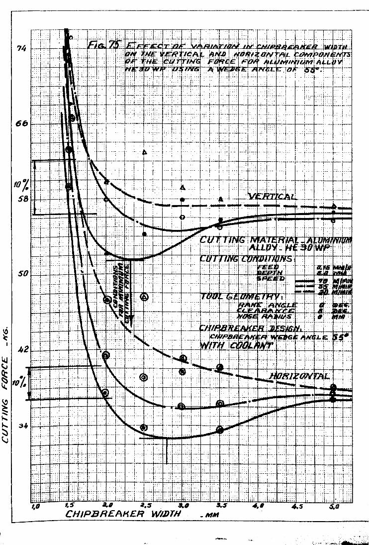
--
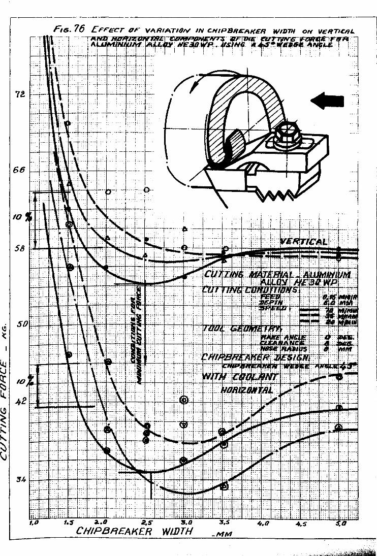
VARIATION IN CHIPBR£AKER WIDTH ON "E~TICHL~ , "fWf,!! .1Ifff1'FrTl:· ! , " j I ~ ~; ~ , I
~i-'-H~Ic·~-+·"";":""-4--4--f-;-+i-+--'+-r'-' I . '. . I , .. ,
..,..c:::::::;.~ _:,
Fus. 76 LFFECT OF
. "1
"'-_:j
... 1
10
'.$ a. 2.S CHIPBREAKER WI.DTH
L-__ ------------------

~ (f) (I)
lLl ~ ~ u -
,
o·-'~·T! i; ! .[: I \ I \' 1. .;__ j .. _;~l._ : . ..., • '., :~,t - ___ ~.~_ ... t__ ~ •• ~~ -''''~~'''' •. '', •. U,!'_'. ;..
~ _ H" ;-:-1 1_ -I ' • ~_,---,T -T=~,uy 1""'= Q.. 0.38 ::, ! , ; _j-':'~....;.._ :_, ___ 1 !-r·-:-f----t-·Tror·-i:£O-;"'C-ri;,y--I-... h =-= :: Nt::: ~ : ;d>1 ;. J . i • 1 . -r- I :. --~, 't' . 'rtL.
lIll : i ... ~ '~Ellt11,11
...... _ -j~--+'l--r"--i'---' -r----: I I .. : • i -. :-ro(Klr~. L£ :;--'--1 II ~ i ~ :: : . I; _~_._~_~_! ___ ; , .~ . 'l-h~--i' -:·t~f~/~-- -.(--:.-+-:-- ttll.;-l ~-,---"+,,.-+-..:i---.i-.:-.t-- ~. __ II, __ ,,_:,_.L . 1 mr:' . -bn::T!1J~£<i-~~- i,. : ' ! d' ., " • I I j mc:rl. ~ IUIY ~ I . I i I: 1=+--+-:~--: . I-T-i---: ---.- '~EW-w£jErjqN'C"Lk"--:44:----i ;--r-+ !-It· +~+ f ---fnn fn!t-u; ~Nr --! ·--i _ (lu!
;; I': :.. ; ! . i i ! ~-L. i I ji
u--1-t-:-+ ----- i-£fflpul -, + -lii" ----I -j uuT--- -)1u -f·, 1.0 1..5 t?o 2.5 3.0 3 S ~' I ' : . I: i I
__________ CHIPBREAKER WIIJTH _1fI1V1 . ,.0 4.5 5.0 S,S 6,0

- 103 -
width was in producing good chipbreaking performance provided coolant
was used to eliminate the appearance of the built-up edge and to
reduce the danger of built-up chips. By examining the chips produced
during these tests it was found that the tendency toward producing
effectively broken chips was increased as the chipbreaker width
approached the value corresponding to 1~fo increase in the cutting
force. However, sometimes built-up and over-broken chips were
produced at that value of the chipbreaker width. From Fig. 75 it
can be seen that the conditions for both minimum cutting force
and cutting force not exceeding 10% for the vertical component of
the cutting force were obtained at a chipbreaker width slightly
smaller than those for the horizontal component of the cutting force.
Figs. 76 and 77 show the effect of the chipbreaker width on cutting Q:'
forces and chip thickness for aluminium alloy using a 45 'wedge
angle. Curves shown in Figs. 76 and 77 are similar to those shown
in Fig. 75. From Figs. 75 and 76 it can be pointed out that the
ratio of chipbreaker width to feed for 550 wedge angle is slightly
larger than that for 45° wedge angle. That means, in order to
obtain good chipbreaking results, the chipbreaker wedge should be
set closer to the cutting edge when using small wedge angles.
o From Fig. 75, for 55 wedge angle, the conditions for an increase
in the cutting force not exceeding 10% was found to be w/s ~10 • .5
for the vertical force and w/s ~ 12 for the horizontal force ..
0' Similarly from Fig •. 76 for 45 wedge angle t the conditions for an
increase in the cutting force not exceeding 10% was found to be
w/s ~ 9.2 for the vertical force and w/s ~ 10'.0 for horizontal
force. However, the numerical values for lower speeds were slightly
higher.. From Figs. 75 and 76 it is clear that the cutting forces
, increase with a decrease in the wedge angle. That is explained by

- 104 -
the fact that the length of the chipbreaker contact increases with
the reduction in the wedge angle. However, extremely large wedge
angles may obstruct the chip fLow. Experimental results obtained
when cutting steel EN1A using a chipbreaker wedge angle of 45°,
Figs. 78-79, show that conditions for cutting force not exceeding
1~~, was obtained at a slightLy larger ratio w/s for both vertical
and horizontal force (w/s ~ 10.5 for vertical force and w/s ~ 12
for horizontal force) than those obtained for aluminium al~oy HE30WP.
The coolant was found to be very effective in promoting good chip
breaking and at some small chipbreaker width it was not possible to
work without coolant.. Such an effect o·f coolant was explained by
the fact that it was responsible for the elimination~ the built-up
edge, and reduction in the friction and temperature effects.. On
the basis of these experimental results it may be concluded for
this type of clamped wedge chipbreaker that, in order to obtain
satisfactory chipbreaking, the chipbreaker wedge need not only to
be set at a certain distance w, which can be expressed as some
multiple of the feed s, depending on the material being cut, but
also to have' a certain angle 0'£ the inclination of the chipbreaker
face (wedge angle) taken in accordance with (w).
To establish the performance of the ground step chipbreakers,:
different chipbreaker dimensions were tested with different materials
at cutting speeds up to 100 m/min.. Figs. 80-83 show some results of
the experimental tests for aluminium alloy HE30WP and steel EN1A
obtained at the conditions mentioned using coolant. Similar to those
results obtained at low cutting speed, the chipbreaker width was· found
to be the most important parameter in controlling the chipbreaking
process. The chipbreaker height, feed and cutting speeds were found
to have a similar effect to those at low cutting speeds.

\ L
~o 2.S"
C HIPB REA ff£ R

,';'.i ;tl~';,;;~;.;;.:~~.l.~;':~~+ •.. -+ .... "'" • .. ·t,···J.;.....:. .. ·~;.;·- ._.- .-~- :.'t~.~ :~;j .. , .. _ ..... : ,~~ -:: il_Lil !!-~ l~; i .... ~~.j > 'e '-,- lei B ±~~ ~~r , 'j ;H~-:') ~ ~ ~: :~~ :;,. , . ,. ' ••. ;;~+..+-. + ..... ~. ~.J~ .... , ..... ~- ...... - .... ~ ~ .... ~~, ... "'r- 'n ...... i .--. .... ~
;·~sfT .•.. S' •• ~ .... ·~ .•• ·.! Et~~~~ }~-..•. f.L!~ ~-;- .••. ';:..~ •• J ••••• '"'1''' ...... ""E:::1I- ,. . .., .. ,.,.. . ... , ,. t' "" ... ,: ...... ," .. ' ... , .•. ; ...... """: . , :.: .:'::',1 ·;·\'1 ' ;...., : .... ,' .. ~C\oo ';:::::: .•.. : ; Ii. '" .... , · .. 1... , . , _, ."" I .. ~~
;:::,: . . ~ ,.; .. : ~ .' .. 1 ..... 1 .::;: :: 1 .··1 . .i.. ; I.: :: . i' Ll . ........... ' ... , . ., ... ;, ";j" ........ ~ ···t .. ·,r-"·f--"· --.. , ... _ .. ~''''r-' .... ! ........ , ........ -1 ... - ... .L ....... "... ~~ . ", ":' .... " .... .. . I .: .:. .:! : .. ' .. ,;':::;': I' . . . . .. ,"1 . Ii' : . ""': +--....... .., ; .. I', , . " .. , ", ". . , .. ... ,
WI¥ - SS3NJ./J/H.1 dlH.J

'9)1- C7~~/.lH3A) 3:JYO..:l

WIN- S3N)lJIH1 dlH:J

.!!J.JI - 711:JI.I./13/\ - 3:JHO.:J :JNI1.1fl:J

~ 'I
ww- d1H.7

- 105 -
4.1.2 Su~~ary of Some of the Experimental Results
It was a part of this investigation to make the task of chirr
control as easy as possible for the machine operator. A solution was
found to the problem of chip breaking within the conventional cutting
conditions. A simple method of finding the dimensions of the chip
breaker was found. Different types of chips were rroduced from
different materials using different geometries of the chipbreaker.
The chip thickness and the chip curl radius were carefully measured
with a micrometer. Different regions of chip breaking were recognised
such as over-broken and built-up chips (the chip length <:5 mm).
(This type of chip is not recommended mainly due to the reduced too1
life or some times breakage of the tool as a result of increased'
cutting force)~ effectively broken (up to 30 mm), broken (over 30 mm)
and no chip breaking region.
the effectively broken chips.
The recommended type was found to be
The chips of up to 30 mm long produced
within the effectively broken region ensures satisfactory chip removal.
In order to find the optimum chipbreaker width which would
give a reliable chip breaking it was necessary to have a diagram of
the chip breaking effectiveness (that means the chip breaking degree
in relation to the chip curl radius/feed ratio). In accordance with
that a series of tests were carried out on aluminium alloy HE30WP
and steel EN1A at different cutting conditions and with different
tool geometries. As a result, chip breaking effectiveness was
established for aluminium alloy HE30WP and steel EN1A. Figs. 53-54
show the chip breaking effectiveness for aluz:tiniuDl alloy HE30HP and
steel EN1A respectively using a rake angle of 150 and cutting speeds
of up to 100 m/min. From Figs. 53-54 it can be seen that in order
to obtain effectively broken chips the chip curl radius should have
a certain value which is some fixed multiple of the feed. Accordingly

- 106 -
the chip breaking effectiveness would best be represented by the ratio
of the chip curl radius to feed (R IS). The reason that the ratio of c
R /S was considered to represent the chip breaking effectiveness is c
based on the experimental evidence derived from Figs. 53-54, and
which show that all points corresponding to lines R /S = 20 for steel c
~~1A and R /S = 25 for aluminium alloy HE30WP, give effectively broken c
chips. By taking into consideration the characteristic ratios of chip
curl radius and feed at which effectively chip breaking was obtained
(namely R /S = 25 for aluminium alloy HE30WP and R /S = 20 for ste~l c c
EN1A), charts shown in Figs. 84 and 85 were arranged for the conditiona
mentioned, so that to provide a speedy method of finding the
dimensions of the ground step chipbreaker. An example of finding the
dimensions of the chipQreaker is shown in each chart.
To use any o£ those charts suppose, for example, we want to
obtain an effectively broken chip when cuttin~ steel EN1A at a cutting
speed of 70 m/min with a feed rate of 0.2 mm/rev. and depth of cut of
3 mm using a rake angle of 150• According to the chart (Fig. 85) for
stee~ EN1A we start from the point corresponding to the feed 0.2 mm/rev.,
and move horizontally till the intersection with the characteristic
line of effectively broken chips (R /S = 20). The projection of that c
point will give the chip curl radius. In this example the bending
radius of the chip curl is 4 mm. According to equation (3.26) this
chip curr.radius for a ehipbreaker height of 0.7 mm corresponds to a
chipbreaker width of 2.46mm. That means in order to obtain effectively
broken chips for the conditions mentioned the chipbreaker step of
0.7 mm high should be grounded at a distance of 2.46mm from th&
cutting edge. Charts shown in Figs~ 84 and 85 are of significant
help to the operator and therefore it is reasonable to suggest that
similar charts should be available for the conditions used in any
particular work shop in order to obtain satisfactory chip breaking
f

~-------.--- - -.-- ---
-! - .. ----T . -~ - - - . - . j
~-t------'----+---:---+-- - -t _~ __ ___ 0-_' __ • ______ .•..
----~-.-- r---' \
---- ---1- --- ..
I I --- _. --1----.. _:
I ' ;'1
---t--~ · _ I ..._1
· I I . ____ . ..l __ . ____ .~
; I I , 'J - ... :
---,--t -.. ~ - -. - .... -t-- --.j
! -t-----j -. -_. -. -. --
I 1---1--1--.+_. - .. _~
'1 ; · I · . t .. -~
i I -I--....l~ ...... -~J-.-.-;.. ----L.... ~-_~
-.1.--; ·-----·1 .... 1
--..J I j
---- -J
~.~.~-+-~~~~~~~.j
11 ]
. ~ I

~ 1---... ____________ , ___________ _
-.. -----?'3ii}wiii":S ::,a3~j-Nji'-~H:i.~QH IGJlIlaIl(/dllO

- 107 -
results. It is important to mention that charts of this form were
(W first developed by Henriksen 7 ". However, the charts shown in
Figs. 84-85 which were obtained for materials and conditions specified
on them are different from those used by Henriksen, in that different
a~proach was made for the arrangement and determination of the results.
It is significant to mention that these charts are strictly
recommended for the conditions mentioned on them,. and any change in
any parameter affecting the cutting process (such as approach angle)
will give different results.
During this work many other experimentaL tests were carried
out such as tests on different chipbreaker wedge configuration (Fig. 86),
and other shapes of the ground chipbreaker. However, it was sugsested
that there is no need for shm'ling all the experimental results obtained
during this investigation" and a typical example will suffice.
4.2 DEDUCTIONS FROH THE ANALYSIS OF THE EXPBRIHEN'L'AL RESUIJTS
4.2.1 Deductions from the Analysis of the Experimental Results Obtained
at Low Cutting Speeds i
1. The chip thickness as well as the cutting forces will have
minimum values at a certain chipbreaker width,. Fiea. 55-69.
2. For ground step chipbreakers the width of the chipbreaker at
which the chip thickness and the cutting force are minimum depends
to a ereat extent on the he~ght of the chipbreaker, Figs. 55-69_
3. The change in cutting speed up to 10 m/min has no significant
effect on the optimum chipb~eaker width at which chip thickness and
cutting force are minimum, Fig. 55.
4. The chi~breaker width at which chip thickness and cutting
force are minimum cannot be considered as the best from chip breakins
point of view. However, for best chip breaking results the chip
breaker might need to be set closer to the cutting edge.


- 108 -
5. The ~ptimum chipbreaker width at which chip thickness and
cuttin~ force are minimum is related to the feed, Figs. 55-69. The
chipbreaker width reduces with the reduction in feed.
6. Positive rake angles over 80 have no si~nificant effect on
the chip thickness. However, negative rake angles will greatly
increase the chip thickness, and cuttinG force, Fig. 87.
7. The range of continuous chips was found to increase with
increase in rake angle.
8. Negative rake angles are characterised by the production of
discontinuous chips, and reduced tool life caused by the extreme
conditions of hieh cutting force and temperature at the cutting zone.
9. The ma.terials ,-.'ere found to fall in the follo\'1ine order in
decreasing the size of the range of discontinuous chips:
Aluminium alloy HE30WP
Steel EN1A
10. The use of chipbreakers may give a reliable chip breaking
with lower forces on the cutting tool.
11. The change in the cutting force and chip thickness may be
explained in terms of changes in the mean coefficient of friction
of the chip-tool contact.
12. The additional cutting force and change in chip thickness
are to some extent affected by the amount of bending of the chip.
13. Coolant is considered to be helpfullin promoting effective
chip breaki~gt due to the elimination of the built-up edge.
14. Chip breaking is bounded by the conditions of lowest permis-
sible chipbreaker proportions to avoid the appearance of the over
broken and built-up chips, Figs. 70-74.

--- -.... ----- .. ----'----------_._-INW- SS3NM:JIHJ. dlH:J

- 109 -
15. The IO\,/est permissible chipbreaker proportions for steel
EH1A are hieher than those for aluminiuM alloy HE30HP, Figs. 70-74.
16. Chipbreaker proportion for satisfactory chip breaking taken
within the condition of lowest permissible chipbreaker proportion
and condition of minimum cutting force and chip thickness. will not
lead to a significant increase in the tool wear.
17. The lathe beins used was found to be satisfactory for the
purpose of this work. However, some of the readings of the dial
gauge dynamometer were affected by the chatter of the tool dymamometer
and machine tool system.
4.2.2 Deductions From the Analysis of the Experimental Results
Obt~ined At ~ieh Cutting Speeds
18. Similar to cutting at low cutting speeds, the vertical and
horizontal components of cutting force as well as the chip thickness
pass through a certain minimum value as the chipbreaker width is
increased, Fies. 75-79. From this it is concluded that the use of
chipbreakers for the purpose of satisfactory chip breaking will
not lead to a significant increase in the cutting force and chip
thickness compared with those obtained from tools without chipbreaker.
However reduced cutting force and chip thickness might be observed.
19. It was concluded that if the cutting force acting on the
cutting tool is not increased by more than 107~ when using a chip
breaker,_ than those acting on the cutting tool when no chipbreaker
waS used, the tool wear will not be significantly increased (this
is con~idered to be so due to the fact that during these tests it
was observed that the number of regrindines required by the cutting
tool at those two conditions were nearly the same).
20. The closer the chipbreaker is set to the cutting edge the
more effective the chip breaking is, and the greater the danger of
over-broken and built-up chips will be.

-110 -
21. Conditions of minimum cutting force and 1~; higher than those
without chipbreaker for vertical component of the cutting force are
obtained at a chipbreaker width slightly smaller than those for the
horizontal component of the cutting force, Fig. 75.
22. For clamped wedce chipbreaker, in order to obtain effectively
broken chips, the chipbreaker wedge must be set closer to the cutting
edge as the wedge angle is reduced. In order to avoid the built-up
chips, the chipbreaker wedge should not be set closer than those
values corresponding to the condition of 10~; increase in the cutting
force.
23. The numerical values of the ratio wls for lower cutting
speeds are strictly higher than those for higher cutting'speeds.
24. The cutting forces increase slightly with the reduction in
the wedge angle, Figs. 75-76, due to the increase in the chip-tool
contact length.
25. The ratio wls corresponding to the conditions of minimum
cutting force and chip tllickness and 1~~ hieher than those obtained
without chipbreaker for both vertical and horizontal components of
the cutting force for steel EN1A is higher than those for aluminium
alloy HE30\-IP.
26. The range of effective chip breaking for aluminium alloy
HE30i'lP is larger than ~teel EN1A.
27. At high cutting speeds r the use of coolant will help
significantly in promoting an effective chip breaking.
28. The manner in \~hich the height of the ground step chipbreaker,.
the feed, the rake angle and cutting speed affect the performance of
the ground step chipbreaker is similar to those at 10\'1' cutting speeds ..

- 111 -
2.4.3 General Deductions from the Experimental Results
29. According to the length and type of chins produced, chip
breaking effectiveness is classified as follows:
(8:) Over-broken and built-up chips (half turn-up to 5 mm long).
(b) Effectively broken chips (half turn, full turn, one and
a half turns - up to 30 mm long).
(c) Broken chips (I'!lore than two turns - over 30 mm long)
(d) Continuous chip - no chip breaking, Figs. 53-54.
30. Effective chip breaking can be obtained at considerably
smaller feed when chipbreakers were used compared with the condition
of discontinuous cutting with tools having no chipbreaker, Fig. 88.
31. The feed necessary to break the chip increases- with the
increase in the cutting speed, Fig. 88.
32. The lowest permissible chip thickness and cutting force
corresponding to the condition of satisfactory chip breaking are not
affected by change in the cutting speed, Fig. 89. However, increase
in the cutting speed will increase the feed necessary to break the
chip.
33. For each material, chip breaking effectiveness is characterised
by ratios of chip curl radius to feed and of chipbreaker width to' its
height for ground step chipbreaker, and by the ratio of chipbreaker
width to wedge angle for clamped chipbreaker.
34. The ratio of chip curl radius to feed corresponding to the
condition of effective chip breaking for aluminium alloy is higher
than steel.
35. The depth of cut has no sicnificant effect on chip breaking,
Fie. 90. However, at depths of cut smaller than 2 mm, the lowest
permissible chip thickness for effective chip breaking is considerably
affected by the chance in the direction of chip flow. Decrease in
depth of cut leads to a decrease in the angle between ~he direction

---------------- ----- ._.- .-- --_._.- ._---_._._----_._-------- ---_._-- _. __ . __ . __ . __ ._-------- --_ .. _._---. __ ._----_._-------,
, - , -.. ". ___ .1___ _ ... __ 1___ I
1 . : '1 i
. -: 1" ,_.:L~_._L~J"- '1-l I ! 1

.---------------------------- -- -- ---- ---------
WW - SS1NJlJIH1


- 112 -
of the chip !low ~nd sid~ cutting edee which will direct the chip
much more easily to contact with the workriece. On the other hand,
t~is will lead to an increase in the chip curl radius, therefore
·makinc the chip breaking much more difficult
36. Charts for finding the chipbreaker dimensions are considered
to be quite reliable for the purpose of desisning tools with chip-
breakers which will produce effectively broken chips.

5.1 GENrnAl DISCUSSION
- 113 -
CHAPTER 5
DISCUSSION
In the last few years much'attention has been given to chip
breaking without any final solution being reached. Nevertheless
many manufacturing organisations are in need of satisfactory methods of
chipbreaking. For the chips to be controlled at the cutting zone and
effectively transported from the vicinity of the machine tool, it is
essential that chipbreakers are used.
In practice, the length of coil produced in cutting operations
can be controlled quite accurately by using chipbreakers, and coils up
to 100 mm lone are preferred. Possibly a consistent lenzth of coil is
attained because of the bending stress set up when the coil waes about,
as the inertia of a certain length is sufficient to cause fracture.
Cracks in the chip develop from the tightly coiled inner edge, and
periodically, one of these cracks extends across the chip to cause
fracture.
When the cut is continuous, curling of the chip by means of a
chipbreaker step or a clamped wedge, is not always SUfficient to ensure
that the chip will break. It often breaks on cominz into contact with
some obstacle. Generally speaking, the coil must be unwound to break
the chip. The lower surface of the chip is smooth and free from flaws,
and the chip will stand severe bending in the direction of increasing
tightness of coiling which puts this surface into tension. On the
other hand, the upper surface of the chip is roueh and full of cracks
and fissures, so that if the chip is bent 60 as to put this surface
into tension, i.e. bent so as to uncoiJ, the chip, fracture occurs
much sooner, than "'hen the outer surface of the chip is comllressed.
For example, the chip produced by a partinz tool coils back on
i tselI. ~,s the coil diameter ~ro"'8, the chip is forced into an

- 114 -
increasing radius of curvature, which means that it is partially
straizhtened, or bent to put tensile stress in upper surface. Hence
when the coil reaches a certain diameter it breaks off. This can
occur with cylindrical turning with zero obliquity, i.e. with the
feed direction vector making a right angle with the cutting edge.
In Chapter 3 chip straightening was sufficiently analysed. It is
justified to say that any obstacle that arrests rotation of the coil
will tend to break the chip.
As cutting speed increases, the chip tends to lose its curl.
The explanation involves reduced friction at the tool face. Friction
gives compressive stress on the under-side of the chip near the cutting
edge, which after a short movement, is relaxed to produce curvature
of the chip. It is also significant that when the chip is blued,
it loses its hardening and gains ductility, and therefore will he
harder to break.
During prolonged cutting. a crater is formed on the cutting
(rake) face of the tool, which gives a chipbreaking effect, especially
when negative rake is used.. The chip must cool down before proper
chipbreaking occurs. This is why better chipbreaking is obtained
when coolant is used. When a high positive rake is used, the chip
curvature is reduced, and the chip remains in contact with the rake
face for an increased distance. Because this gives additional
friction, it may nullify th~ reduction in power expected from the
theoretically low strain in the chip. Here it may be expected that
a chipbreaker would lift the chip away from the face of the tool
at a short distance from the cutting edge, thus reducing friction
and cutting force.

- 115 -
The chipbreaking problem is more acute for finishing operations
than for roughing. In many roughing operations, an irregular depth of
cut tends to prevent the chip from becoming too long. As the chip-
breaker is brousht nearer to the cutting edge, vertical and horizontal
components of cutting force~ chip thickness~ and tool temperature will
increase. Accordingly extreme conditions of high cutting force and
temperature will reduce the tool life. To obtain best chipbreaking
results, the chipbreaker should be set back from the cutting edge a
distance equal to some fixed multiple of the feed, depending on the
material being cut. For clamped chipbreakers the chipbreaker wedge
should have an acute angle to avoid clogging. For this type of chip-
breaker, provided the chip impinges on it, the height of the chip-
breaker face is not significant. For any setting, chipbreaking
performance varies with feed rate. For a very light feed there will
be no chipbreaking action; at the other extreme, a feed rate will
be reached when jamming-up occurs.
Apart from the ground step and clamped chipbreakers, various
profiles of tool tend to promote breaking of the chip. With a normal
rake angle, say +90• a negative rake land may be formed on the cutting
edge of true width equal to ~ to t of the feed, which is usually a
land width of 0.10 to 0.15 mm, but not more. This tends to promote
chip curl. A radiused cutting edge may be helpful, say up to 0.1 mm.
However, if this is used for low feeds,. say 0.05 mm/rev •. a very poor
finish results.
A chipbreaker groove can often give satisfactory chipbreaking.
For best chipbreaking performance the groove must approach the cutting
edge to within a small distance comparable to the feed rate. The groove
type chipbreaker is characterized by low cutting force. This is due
to a reduced length of the chip contact path on the rake face(81,82,85)
where friction is high.

- 116 -
DISCUSSION OF THE EXPERIMENTAL RESULTS
From the analysis of the experimental results obtained during
thiS work it is well established that cutting forces acting on the
tool when using a chipbreaker can be less than the cutting forces
t" ~ when no chipbreaker is used. Therefore, it is justified to
ac 1 n u
that the introduction of chipbreaker into the geometry of the SUegest
tools will not lead to an increase in the cutting forces cutting
the tool, but may even give lower forcea. By considering acting on
acting on the tool as a parameter affecting the tool wear the force
theV are not directly related), the reduced force obtained (althOUgh v
when chipbreakers are used can therefore be seen as an improvement
in the conditions effecting the tool wear. On the other hand incorrect
" aker proportions may lead to an ,extensive increase in the force ch1pbre
rature acting on the cutting face of the tool. This occurs and tempe
It of over-breaking and building-up of the chips in the as a resu
f the chipbreaker when small chipbreaker width is used. vicinity 0
" "nate such a possibility the chipbreaker proportion ratio To el1m1
d be taken larger than those corresponding to the lowest permshoul
" 1 chipbreaker proportion for effective chipbreaking. Physically, iss1b e
1 that on moving a chipbreaker nearer to the cutting edge,
it is c ear
t " g force may be first reduced due to the reduced tool-chip the cut 1n
but ultimately the force must increase due to obstruction contact area,
of the chips. The assumption made during the course of this work that
if the cutting force is not increased by more than 10% the tool wear
b excessively increased was verified by tests. will not e
However, a
theoretical examination of the cutting forces would be very useful.
"~nificance of this condition is in providing effective chipThe S1~
king when chipbreakers were used. Therefore effective chipbreaking brea

- 117 -
may be characterized by the conditions of lowest permissible chipbreaker
proportion ratio and 1~~ increased cutting force.
In order to design a chipbreaker which would give a satisfactory
chipbreakine for any particular material it is considered to be
attractively simple procedure if the material could be characterized by
two experimental factors only, these factors being ratios R /S and L/R. c
The ratio of chip curl radius to feed expressing a satisfactory degree
of chipbreaking while the chipbreaker proportion ratio expressing the
condition for minimum cuttincr force. According to the experimental
results obtained during this work,tneratio R /S was found to be the c
most reliable parameter in determining the degree of chipbreaking.
Different chip curl radius corresponds to different degrees of chip-
breaking. The effect of the feed on chip curl radius is determined
by the degree of chipbreaking. For any set of cutting conditions,
tool geometry and cutting material the chipbreaking effectiveness is
characterized by some constant R /S ratio. For example, effective c
chi,breakine for the conditions mentioned in Figs. (53 - 54) when cutting
aluminium alloy HE30\JP and steel EN1A can be obtained at R /S = 25 c
and 20 respectively. Thechipbreaker ratio expressing the force
condition at the cutting face of the tool should be taken in agreement
with ratio R /S so that to obtain effective chipbreaking without a c
significant increase in the cutting force.
On the basis of the experimental as well as the theoretica~
results it is justified to say that chipbreaking effectiveness is
deyendent on chip curt radius, feed and the properties of the material.
In appendix I and II a simple theoretical analysis of the chip
breaking is shown. Here also the chipbreakine effectiveness was found
to be determined mainly by the parameters mentioned earlier. Nakayama(80)
and Okushima, Hoshi and FUjinawa(101) have concluded that limiting

- 118 -
condition for chip breakine is determined only by radius of the chip
curl, the material to be cut and chip thickness.
The theoretical expressions shown in Chapter 3 as well as
those in appendix I expressing the chipbreakers proportion in terms
of chip curl radius can be used quite satisfactorily for the purpose
of designine ground step and clamped chipbreakers. By substituting
the value of chip curl radius corresponding to effectively broken chips
toeether with constant C1 and C2 which depend on the cutting material,
tool geometry and cutting conditions in equation (3.26), the chip-
breaker dimensions can be calculated. However, the effects of cutting
speed and depth of cut in equation (3.26) are not significant. This
is due to the fact (based on the exrerimental results) that the cutting
sreed will not lead to a significant change in the chip curl radius
when the feed used is not less than O.oS mm/rev., however, at feeds
smaller than 0.08 mm/rev. reduction in the cutting speed ''lill result
in a decrease in the chip curl radius in the direction of tightening
the chip coil. During this work the change in depth of cut was found
to have no significant effect on chip breaking. However, reduced
de2th of cut less than 1.5 mm will lead to a reduction in the chip
flow angle (anele between the direction of chip flow and side cutting
edge)., Al thouSh this will lead to an easier contact of the chip with
the work-piece which may give easy chip breakine. reduction in chip
flow angle will lend to an increase in the actual radius of the chip
flow in the direction of harder chip breaking. Similar effects of
cutting speed and depth of cut on chip breakine effectiveness have
been recocnised by Hakayama(SO) and Okushima(101). Yoshida(108) has
also con!irmed that increase in depth of cut leads to an increase in
the chip curl radius.
Simply spe~kine the chip breakine effectiveness can be
controlled quite effectively by means of the chipbreaker proportion

- 119 -
ratio (IJIDTH/:-!EIGHT, L/H t Fig. 37, for ground step chipbreaker and
the factor of chipbreaker width to wedge angle, W~. Fig. 38,
for clamped wedge chipbreaker) by taking into consideration the ratio
of the chip curl radius to feed (R Is). c
5 3 RECO~:ENDATIONS FOR FUTURE WORK ON CHIPBREAKING • In the light of this recent work the following points were
recommended for the future attention:
1. The mode of action of the notch chipbreaker in the
tool face is not very well understood, and exploration
of the flow would be useful, though this might mean
elaborate quick-stopping techniques.
2. Measurement of chip ductility. to be related to the
cutting conditions and metallurgical condition of
the chip.
3. Visual and photographic studies of chip formation.
4. A theoretical method of examining cutting forees as
affected by the chipbreaker would be very useful.

- 120 -
CHAPTER 6
CONCLUSIONS
On the basis o~ the experimental results obtained during
this investigation, the following conclusions were drawn:
1. For ground step chipbreaker" the ratio of the width of
the chipbreaker (the distance from the cutting edge of
the tool to the chipbreaker wedge) to its height is the
most significant parameter in controlling the chipbreakine
process.
2. For ground step chipbreaker, the optimum chipbreaker
width correspondine to a satisfactory chipbreakine
increases with the increase in the height of the chip
breaker and the feed,(Figs.55-56).
3. In roughing operations, chipbreaking can be satisfactorily
a~hieved by changing the feed.
4. For clamped werlge chipbreaker, the wedge angle (angle of
the inclination of the chipbreaker wedge from the cuttig
face of the tool) as well as the chipbreaker width are
the most significant parameters in controlling the chip
flow. The best results were obtained with wedge anele
400 to 50°.
5. For both ground step and clamped wedge chipbreaker, the
cutting force as well as the chip thickness pass through
a certain minimum value as the width of the chipbreaker
is reduced.
6. Degree of chipbreaking can ~e specified in terms of the
types of chips produced.
- 121 -
7. For any particular material, the chipbreaking effective
ness can be represented in terms of the ratio of chip curl
radius to feed which expresses the degree of chipbreaking
and the chipbreaker proportions which expresses the condition
for mininum cutting force.
8. Chipbreaking effectiveness is affected by the feed and
cutting speed only through the change in the chip thickness.
However, parameters not affecting the chip thickness will
have no significant effect on the chipbreaking effective-
ness.
9. The chipbreaking effectiveness can be expressed in terms
of theoretical relationships. Accordingly charts for des
ignine effective chipbreakers can be drawn.
10. Chipbreaker proportions are limited on the one hand by the
need to get sufficiently broken chips and on the other hand
by the need to avoid an excessive increase in cutting
forces, which should not increase by more than 10 % •
11. Use of chipbreakers may improve the conditions at the
cutting edge (by giving reduced cutting force).

-122 -
APPENDIX I
THEORE'1:'IC.U. ANALYSIS OF CHIP CURLING
r?,;:! ';NISi'l FOR BOTH Cl.AHPED HSDGE AND
GROUND STEP CHIPBREAKERS
The mechanism of chip curling by the action of the chipbreaker
has been analysed theoretically by Henriksen(71). Okushima(101).
(80) . (105) (107) Nakayama • Dawe and RubensteJ.n • Trim and Boothroyd .' this
recent work and others. Each auther has suggested a different theoretical
explanation of the mechanism of chip curling by the chipbreaker. However
some of these theoretical analysis were in good agreement with the experi-
mental results. In this appendix the chip curling mechanism will be
analysed from different aspect.
When the chip is straightened (as shown in Figs.91a-c and 92a-o)
from its initial radius R to a radius R , the strains and stresses c
involved can simply estimated.
______________________ NOMENCLATURE
R = Initial chip curl radius or flow
circle radius, Figs.91 & 92
R = Final chip curl radius caused by c
the action of an obstacle. Figs.
91 & 92
£ = Strain in the outer fibre of the
chip (beam)
t = Chip thickness c
6 = Flow stress o
E = Modulus of elasticity
~ = Angle of the inclination of the
chipbreaker wedee from tha
cutting (rake) face of the tool.
\-/ = Distance from the chipbreaker
wedge to the cutting edge of
the tool, Fig.91 C'
€. -f- Strain corresponding to the
rupture of the chip
C = Constant depending on the
properties of the material
being cut
1.= Chip-tool contact length
K = Constant for a given material
H = Height of the step of the
ground step chipbreaker
L = Distance from the cutting edge
of the tool to the heel of the chipbreaker


-lJ
-
i

- 123 -
The strain in the outer fibres of a straight beam of thickness
(tc
) bent to a radius Hc is simply(104)
E.= t
+ c --2R
c
Hence, when a beam of radius R is bent to a new radius of Rc' the strain
in the outer fibre is
e= t
+ c --2
1 1 (--- ) R R c
If the str~i5htening is elastic, the product (E€) cannot exceed the
flow stress 60
• Hence the maximum change of radius is
1 1 --~----H Relastic
= 2 6: o
E t c
J . d N k(104) f . According to Cook, haverl an aya or a typlcal steel chip.
6 = 100,000 lb/in2 , E = 30 x 106
lb/in2
, t = 0,005 in; R = 0,020 in. o c
Elastically, the initial radius of the chip curl could be increased to
R = 0,0205 in., so it can be seen that the elastic effect is insignc
ificant and can be ignored. This means that the final chip curl radius
is determined only by the plastic bending action.
As the chip comes in contact with the chipbreaker, it receives
an extra bending action imposed by the chipbreaker. The final strain
in the chip (as a result of its contact with any obstacle) will be
calculated according to equation (A1.1).
However, from the geometrical relationships, Fies. 91c-and
92c the initial chip curl radius (i.e. chip flow circle radius) for
clamped wedee and ground step chipbreakers can be expressed as
follows:

- 124 -
. (80) For clamped wedge ch1pbreaker, Fig_ 91c.
R = 'r: cotft/2
For eround step chipbreaker(71), Fig. 92c
R = 2H
Hence from equations (AI _1), (AI _2) and (AI -3) we obtain:
For clanped wedse chipbreaker
t E = --!?- ( __ ..;..1 __
1 -- ) 2 W cotp/2 R c
For sround step chipbreaker
€= t
c 2H 1 (~;;....---- - )
L2 + H2 R 2
By considering·
1 1 -~ -t===:O R R c
c
Equations (AI _4) and (Ar -5) will become
For clamped wedee chipbreaker
1 1 = -----
R vi cotj?J/2 c
For cround step chipbreaker
1
R c
= 2H
2 112 L +
Thp. chip will break away when the bending strain produced in
the chip reaches a critical value correspondine to the rupture of the
chip material. Therefore, equations (AI _4) and (AI -5) will become:

- 125 -
For clamred wedge chipbreaker
t E:.fo = _c (1/~':cotfo/2 - 1/R )
2 c
or 1 1
2 E..f = --
R W cotfi/2 t c c
For ground step chipbreaker
t 2H 1 Ef
c ( = L2 + H2 --)
2 R c
or 1 2H 2 ~£ = L2 + R H2 tc:
c
By taking into consideration the effect of chip~tool contact
length on the chip curl radius, the effective chipbreaker width will
be W -fand L -e for both clamped wedge and ground step chipbreakers
respecti vely e But according to Creveling" Jordan and Thomsen (106)
-f= K t c ::: t t (K =-1) c
Hence eClua.tion (ArB) will become:
1 1 2 E.f =
R (w-t ) cotj3/2 t c c c
Putting 2 ~f = C in equation (A1 .10) we get
1 1 C = R (W-t ) cotj3/2 t
c c c
And similC\rly equation (Ar e 9) will become:
1 2H C = (L-t )2 + H2 R t
c c c

Puttin~ W ff t" = W - t e ec 1ve c
1 1 - =
- 126 -
and L effective
R (\! -t ) cot ft/2 c c
1 2H - = )2 + H2 R (L-t c c
= L - t c in equations
similar to that of Trim and Boothroyd(1 07)
equations (A1 .11) and (A1
.12) that the
final chip curl radius for any particular set of cutting concH tiona
Equation (Ar 14) is
It can be seen from
is determined by the chipbreaker proportions, the properties of the
material beine cut and the chip thickness (or feed). It can also be
seen that the chip curl radius decreases with an increase in the chip
thickness (or feed). That explains why built-up chips occurs at large
ieeds. Fie.93 shows the comparison between the experimental and the
theoretical (calculated according to equations AI _2, AI .11 and A1 .14)
values of chip curl radius for a clamped chipbreaker of 450 wedge angle
and with 1" mm chipbreaker width. The experimental results seem to
be in better agreement with the results calculated according to equa-
tion AI." rather than those obtained from equations A1.2 and Ar .13-

- ---------- -- ----
- 127 -
APPENDIX II
FORCES ACTING ON THE CHIPBREAKER
In order to obtain satisfactory chipbreaking result with
comparatively long effective life, the chipbreaker must be designed
so that to minimize the force acting on its surface. The main force
acting on the chipbreaker is chip curling forc~ (force necessary to
curl the chip as it leaves the cutting edge. Nevertheless the
chipbreaking force (force necessary to break the chip as it comes
in contact with an obstacle) has some effect on the chipbreaker.
However, this force has an intermittent action and comparatively
small. On the basis of this, the chip curling force will be con-
sidered as the main and only force acting on the chipbreaker. \
_____________ NONENCLATURE ---------------
MB = bending moment at the jU= coefficient of friction
cutting edge B ·between the chip and the
F = resultant chipbreaker chipbreaker
force F = vertical component of v
R = radius of the chip the chipbreaker forc&
flow circle, Fie. 94 Fh = horizontal component of
jJ = chipbreaker wedge the chipbreaker force
angle, Fig. 94 b = chip width
e = angle between the resultant t = chip thickness c
chipbreaker force and the ~ = yield stress of the chip
vertical to the chipbreaker
face, Fig. 94

- 128 -
According to Nakayama(80). the bending moment at the
cutting edee B of the tool FiZ.94 caused by the chipbreaker
force (chip curline force acting on the chipbreaker) is:
l'~B = F x Be = F x R SinY3 + B) - Sine
e -1 0 A -1 (,; ) = tan .JlL- = 90 - J- - tan F Fh
From the condition of the stress distribution in the chip at
t " d B h "F" 95(80) b" the cu t lone e ge as sown lon log. • we 0 talon.
Accordingly from equation (AII .1) and (AII -3) we obtain:
F = 4R Sin(fi + e) - Sin a
Equation (A11.4) is the equation of the force acting
on the chipbreaker.
The action of'the cutting forces acting on the chip-
breaker has also been investigated by Subramanian and Bhatt
(109) acharyya _


- SS3N>I.:JIH.l dlH;:)

1.
6.
8.
10.
11.
12.
- 129 -
Bl13LIO~
K. G. Lewis
N. E. Woldman and R. C. Gibbons
C. Rubenstein
E. M. Trent
p, L. B. Oxley end M. J. M~ Welsh
H. E. Enahoro and M. J. M. Welsh
E. M. Trent
M. E. JVdon
H. Opitz and VI. Konig
I. A. Time
K. A. Zvorkin
A. A. Briks
"ille Machinability Concept", Metal Treatmtmt, Vol. 24-, No. 14-2, 1957, p.p. 263-271.
"Machino.bili ty and Machining of Metals", McGraw-Hill Book Co., London, 1951, p.7.
"fue Rule of Surface Energy :in Metal Cutting", Machinability Conference, ~e Iron and Steel Inst., Oct. 1965, p.p. 11-15.
"Th.e Relationship Between Machinability and Tool Wear", Machinability Conferenoe, The Iron and Steel Inst., Oct. 1965, p.p. }1··4.7o
11 On Machinability", Eng. Digest, 1.'01. 26, No. }, 1965, p.89.
"The Relevance of the Mechanics of Metal Cut ting to Machinability", College of Aeronautics, Cranfield, Co.A Memo, M and P No. 74., August, 1965.
"Metallurgioal Changes at the Tool/Work Interf'ace ll , Machinability Conference, ihe Iron and Steel Inst., Oct. 1965, p.p, 45-55.
"Influence of Metallurgical structure an the Machino.bili ty of Wrought Aluminium Alloys.'f, Machinability Conference, 1he Iron and Steel Inst., Oct. 196C;, p.p. 57-60.
"Basic Research on the Wear of Carbide cutting Tools", Yach:inabill.ty Conference, The Iron and Steel !nat., !bt. 1965, p.p. 117-123.
"Resistance of Metals and Wood to Cutting", (Soprotivlen~e metalov i deriva rezan~) 1870.
"ilork and Force Necessary for Separating a Metal Chip", (Rabota i ysil:1ye, neobchodimY,ye ~a otdelen~ metallichesko1 struzhld, Technicheskii sbornik i vestnik p~8hlennosti), 1896.
"Cutting of Metals", (Rezony:iye metallov), 1896.

16.
18.
20.
21.
22.
23.
24-.
25·
26.
- 130 -
V. Piispanen
H. Ernst and M. E. Merchant
M. Field and M. E. Merchant
N. H. Cook, I. Finnie and M .. C. Shaw
N. N. Zorov
E. H. Lee and B. W. Shapper
R .. Hill
K. Okushima and K. Hitomi
K.Nakayama
K. Okushima and K Hitomi
D. Keceaoglu
D. G. Christopherson, P. L. Oxley and lI. B. Palmer
A. A. D..yushin
A. N. lI.al.ova
N. H. Cbok and M. C. Shaw
"~eor,y of Formation of Metal fJhips", Journal of Applied HJiysics, Vol. 19, 1948, po876.
"Surface Treatment of Metals - Chip Fonnation, Friction and High Quality Surfaces", A.S.M. Symposium, p.299.
"Mechanics of Fonnation of Discontinuous Chip in Metal Cutting", Trans. A.S.J4.E., 19~9, Vol. 71, p.~21.
"Discontinuous 0hip Formation", Trans. A.S.MoE., 19~, Vol. 76, p.153.
"Metal Cutting Mechanics", Pergamon Press, London, 1966.
"~e Theory of Plasticity Applied to the Problem of Ihchlning", J .Applied Mech., 1952, Vol. 19, p.238.
"The Mechanics of Machining, A New Approach" J.Mech. & Phys. of Solids, Vol. 3, 19~, p.p. ~7-53.
"An Analysis of the Mechanism of Orthogonal Cutting and its Application to Discontinuous Chip Formation", J .Eng. for Ind., Trans. A .. S~}4.'E., Ser. B, Vol. 83, 1961, p.~5.
~A study on Mechanism at Metal Cutting", J. of Socie ty for Precision Mechanics, Vol. 23, 1957, p.p. 528-532.
"O!:l'the Cutting lkJchanism for Soft Me tala" , Trans. J.S.M.E., Vol. 23, No. 1~, 1957, p.p. 67~-680.
"Shear Strain Rate in Metal Cutt.ing and its Effect on She r Flow Stress", Trans. A.S.M.E., 1958, Vol. 80, pt. 1, p.i58.
"Orthogonal Cutting of Work Hardened Material" I Eng:ineering, Vol. 186, 5th July, 1958, p.113.
"P1asticity", (P1astichnost), Gostekhizdat, 1948, U.S.S.R.
"Handbook", (Kratki spra·roclmik metall1ota), (in Russian), Moscow, 1965.
"A Visual Metal Cutting Study", Mechanioal Engineering, No. 11, Vol. 73, 1951.

28.
30.
33.
JIt,.
37.
4.0.
A. B. Albrecht
w. B. Palmer and P. B. Oxley
H. E. Enahoro and P. B. Oxley
H. Banerjee and W. B. Palmer
P. W. Bridgman
C. Zener
K. Hitomi
E. H. Lee
S. Kobayashi and A Shabik
N. N. Zorev
K. Hoshi
K. Naka\Yama and K. Iguchi
M. Okoshi QZld T. S6.ta
- 131 -
"Chip Studies Roveal What Happ~nsn, llie Machin is t, No. 26, 97, 1953.
"'lhe Mechanics of Orthogonal Machining", Proc. ]nst. of Mech. Eng., Vol. 173, 1959, pe623.
".An Investigation of the Transition from a Continuous to a Discootinuous Chip :in Orthogonal Ma.chining", Int. J. Mech. Sci., 1961, Vol. 3, p.p.14.5-156.
"Meto.l Cutting with a Disoontinuous Chip", Machine Tool Design QZld Research 1965, p.405.
''Effects of High Shearing Stress Comb:ined wi th Hydrostatic Pressure", Phys ~ Review, 1953, Vol. 48, p.825.
"Micromechanism of Fracture", Fra.~ture of Metals, po3.
"Fundamental Machinability Research in Ja.pan", J. Eng. for Ind., Trans A .. S.M.E. Sere B, Vol. 83, 1961, p.531•
"Plastic Fl()l;{ Problem arising from the Theory of Discontinuous Machinmgll, 1rans. A .. S ... M"E., 1954., Vol. 76, p.189.
"Chip Fonnation with Varying Undefonned Chip 'lhickness at very Low Speed", J 0 ot Eng. for Ind., Trans. A.S.M.E. Vol. 86, 19~, p.p. 389-39~.
"Nonna! Forces and Friction Forces During Free cutting at an Acute Angle", (Nonnalnye sily treniya pri kosougolnan. rezaniya metallov), Trudy Ts N:i 1tlash, book, 1948, U.S.S R.
"On the Bull t-up Edge and Counterplot for it", Trans. J.S.M.E., Vole5, 1939, p.p. 137-148.
"Studies on the Bui! t-up Edge", Journal of Socie~ for Preoision Mechanics, Vol. 22, 1956, p.p. 104-108.
''Fozmation and Disappearance of Bull t-up Edge :in Machining", Journal of Scientific Research Inst., Vol. 33, 1957, p.p. 155-164..
4.1. Meyer and J. D. Cumming "Handbook", Toronto, 1956, 2nd edition.
4.2 R. Holm "Electric Contacts", Hugo Gebers, Porleg, Stockholm, Sweden, 194-6.

'-4.
4.6.
~.
so·
52.
5lf..
55.
56.
-132 -
H. Ernst and M. E. Merchant
~. P. Bowden and. D. Tabor
M. C. Shaw and E. P. Macks
S. Kobayashi and E. G. 'lhans8ll
A. M. Rozenberg end A.. N. Yeremin
A. N. Yerearln
A. I. Is~v
M. C. Shaw, D. Piggot and Z. P. Richardson
A. Nad&1'
M. C. Shaw
T. Bevan
1(. B. Moore
A. Amsler
J. D. Hottman
"Surface Friction of Clear Metals" , Proceedings of the Special Summer Conference on Friction and Surface Finish, M.l.T., Cambridge, Mass., 1940, p.76.
"The Friction and Lubrication of Solids", Oxford University Press, Oxford, England, 1950.
"Analysis and Lubrioation of Bearings", McGraw Hill Book Canp., Ino., New York, N.Y., 1949.
"~e Role of Friction in Metal Cutting", J. Eng. for Ind., Trans. A.S.M.E., Sere B., Nov. 1960, p.32~.
"Contribution to the Theor,y of Metal Cutting", (Kteorii protsessa rezaniya metallov), stanki i instrument, Ne. 10, 19~9, U.S.S.R.
"Blysioal Nature of Hlenomena when Cutting Steel", (Fizicheska3'a syshnost yavlenii pri rezanii stali), Mashgis, 1951, U.S.S.R.
"Prooess of Surface La3"er Formation During Maohining of Metals bY Cutting", (Protsesa obrozovaniya poverkhnostnogo aloya pri obrobotke metallov rezaniem), Mashgis, 1950, U.S.S.R.
"b Effect of the Cutting Fluid UpGtl Chip-Tool Interface Temperature", Trans. A.S.M.B., 1951, No.1, Vol. 73.
"~or,y of Flow and Fracture of Solids", Eng. Sooiety, Volo 1, McGraw-Hill Book Comp., Inc., New York, N.Y., 19 ), p.349.
"Metal Cutting Principle", 3rd Edition, ihe M.I.T. Press, Massachusetts Inat. of ~chnology, Cambridge, :Mass., 1965.
"1he 1beor,y of Machinea", 3rd Edition, Longman, 1956.
"Theor,y and Application of Me~hanical Engineering Measurements", New York, Van Nostrand, 1960.
"Sane New 'l:,ypea ot Dynamometers", Proc. Inat. Mech. Eng., 1911, p.603.
"A It'draulio Dynamaneter", 'Jrans. A.S.M.E. 1896, p.~71.

57.
58.
59.
60.
61.
62.
6.3.
61.-.
65.
66.
68.
70.
w. F. Durand
w. H. Bird and B. P. Fairfield
'iT. R. Backer and E. J. Krabacher
H. C. Town
H. C. Town
o. w. Boston and C. J. Oxford.
P .• Koenigsberger, K. D. Marwaha and A. S. P. 8abbenval
O. W. Boston
Lanachenko
A. Vallance and V. L. Doughtie
R. J. Roark
v. M. Faires
o. R. Freberg and . E. N. Kemler
E. K. Henriksen
Me. E. Muller
- 133 -
"Improved Transmission D,ynamumeter", Trans. A.SoM.E., 1907 (28), po697.
"A Mst Drill Dynamometer", Trans. A.8oM.E., 1905, p • .355.
"new Techniques in Metal Cutt1ng Research", Trans. A.S.M.E., 1956, Vol. 78, pt. 2, p. 1z..97.
"Teohnology of the Maohine Shop", London (Lonf}D8n, Green &: Co.), 1951.
"Cutting Tools, Jigs and Fixtures", London, Odhams Press, 1960.
"Ibwer Required to Drill Cast Iron and Steel", Trans A..S~M.E., 1930.
"Design and Performance of TRo Milling Force Dynamometers", J. !nst. Prod. Eng., Dec. 1958, p.727.
"Research in the Elements of Metal Cutting", Trans. A.S.M.E., 1926, p.749.
"Pneuma tic Lathe Dynamometer", Hussian Eng. Journa:, 1961, Vol. 41, Issue 2, p.p. 47-49.
"Design of Machine Members", New York, MCGraw-Hill Book Co., 1951.
"Handbook of Formulas for Strengths of Materials", 3rd. ed., London, McGraw-Hill Book Co., 1954.
"Design of Machine Elements". New York, (McMillan). 1955.
UKra tkii spravoc~ik maolrlnoatroi tela", MOBOOW, 1963.
''Elements of Mechanical Vibration", 2nd ed., New York, 1952.
"Chip-breaker Research", Tooling, Oct. 1955, p.p. 20-28.
lI~e Control of Chip Form in Tum:lngtt, Werkstattsteohnik u Maschinenbau, v. '-'7, No.6, June 1957, p.p. 269-273 M.T.I.R.A. Translation.

- 134 -
73. E. Bickel "Control of Chip Form while Tlxming" , Wdcrotechnic, V. 11, No.6, Dec. 1957.
74.. K. Okushlma and "On the Behaviour of the Chip in Steel K. Mjnato cut-ting", J.S.M.E., V. 2, No.5, 1959,
p.p. 58-64..
75. E. Eugene "Experimental study of Combined Influence ot Sharpening Angle of Tool and of Cutting Speed on Modalities of Chip Formation", Microtechnic, V. 11, No.5, 1957, p.p. 223-230, No.6, 1957, p.p. 277-2~.
7p. M. Kronenberg "'!he Inclination of the Cutting Edge and its Relation to Chip Curling", Tool Engineer, V. 14., No.9, 1954., p.p. 12-15.
n. w. A. Carter "Economics of Broaching", Aircraft production V. 10, Nos. 111 and 112, Jan. Feb., 1948, p.p. 19-23, 62-64..
78. F. P. Malikov ~fect of Chip-breakers on Cutting Foroe in BroacM,ng", Stanki i Instrument, V. 20, No. 2, Fsb~, 194.9, p.p. 17-18.
79. V. A.. S:inopalnikov "Cutting Edge Radius in Cemented Carbide, Tools 11, E. F. Eikhmans, Mach1n&s and Tooling To Vol. 36, No.6, p.4.;, 1965.
80. K.Nakayama "A study on Chip-Breaker", J. at -tb,o J cS.l!.E., 1962, 5, 17, p.p. 142-150.
81. V. M. Lutov "Selecting the Optimum Size of Chip Breaking Grooves", Machines and Tooling Vol. 33, No.7, p.27, 1962.
82. A. F. Knbanov "S'iraight Turning Tool with Chip-breaker", Machines and Tooling, Vol. XXXI, No.9, p .. 42, 1960.
83. V. V. Igoshin "Tools with Chi~ Curling Grooves", Machines and Tooling, Vol. 36, No. 12, p.37, 1965.
84.. Yu. G., Proskuryakov, "Chip :Breaking in the Machining of steel", V. N. Petron, and Maohines and Tooling, Vol. 33, No.7, G. A. Fedordv p.26, 1962.
85. I. I. Bazhenov "Chip-Breaker Grooves and steps", Machines and Tooling, Vol. XXXIIL, No.4, 1962, p.42.
86. M. O. Nodel Man "Cutting Tools with Fine Chip-brenker Grooves", Machines and Tooling, Vol. 33, No. '12, p.39, 1962.
87. I. I. Skuro.tov "New 'l)pe of Chip Breaking Step", Machines and Tooling, Vol. 33, No.1, p."" 1962.

88.
90.
91.
92.
93.
94.
95.
96.
97.
98.
99.
100.
101.
- 135 -
Yu., G., ProskuIyakov,
N. M. Iot't'e
A. S. Kondra toY
G. I. Kiselev
P. S. Polgov
V. N. Baranov, Yu., E. Zakharov, V. E. Moiseev
V. N. Podu,yaev, end A. M. Bezborodov
I. H. M. Almandelawi and D. S. Dugdale
J. C. Koza.cka
N. N. Zakharov and B. I. Ivro.gimov
I. D. KopClleve
O. Schnellmann
M. Weill
K. Okushima, T. Hoshi and T. Fujinawa.
"Chip Breaking in Fo.cing the Fnds of Welded Pipes", Machines and Tooling, Vol. 36, No.6, p.46, 1965.
"Dynamic Chip-breaker", Stanki i Instrument, No. 11, 1949, p.p. 18-20, M.T.I.R.A. Translation.
(The Results of Tests with the Dynamic Chip-breaker", (Russian), Stanki i Instrument, V. 21, No.4, April 1950, p.p. 21-22.
"Resul ts of a Study of the Performance of a Dynamical Chip-breaker", Stanki i Instrument, V. 22, No.4, 28 April 1951, M.T.I.R.A. Translation.
"Chip-breaker with Automatica1~ Adjustable Step", Machines and Tooling, Vol. XXXI, No.6, p. 38-40, 1960.
"Chip Breaking Methods in Turning Ductile :Metals", Machines and Tooling, Vol. ,34, No.1, p.16, 1963.
"Using Self-Excited Vibrntials -£ or Chip Breaking", If,achlnes and Tooling, Vol. 3lf., No.1, p.19, 1963.
"ChipF'onnation ani Chip Breaking Process in Metal Cutting", Progress report, University ot' Sheffield, Nov., 1968.
"How Tool Design Affects Cutting Forces", Amer. Machinist, V. 100, No. 14, 2 July 1956, p.~. 85-7.'
"Rydraut!.ic Copy Lathe Modified f01\ Jrnterrupted Worldng Traverse, Maohines and ~oling, No.5, 1964, p.p. 31-33.
"Breaking a Continuous Chip by Int~rrupted Cutting It , Machines and Tooling, V. 34, No.6, 1963, pcp. 31-6.
"Chip Breaking", Ai.""Ora.:f't Production, V. 16, No. 5, ~my 1954, p.p. 168-172.
"The Technique of Vibrating Tools", (Gonnan), :Machines Frannaises, No. 48, December 1964, p.p. 51-59.
"On Behaviour of Chip in Steel Cutting", Japan Soc. Mech. Eng. Bull., V. 3, No. 10, ~ 1960, p.p. 199-205.
102.
103 .
104 .
105.
106.
G. R. Ponkshe
t· . r· . Lamn
I • H. Cook , P. Jh:lveri
and • a ak
C. C. Dawe and
C. Rubenstein
J . ~ . reveling , T. F. Jordan
and E. G. Thomsen
107. A. R. Trim and
7 . Boothroyd
108 . Yoshida , Serizawa and
Toida
109. T. L. Subramanian and
A. Bhattacharyya
67* J . P. Den Hartog
71 A E. K. ~enriksen
- 136 -
Tr ans . Am . Soci. Mech~ Bngrs., Series B. v. 89 , p. 376, 1967.
Engineering , V. 187, ,.444~ 1959.
"The Hechanism of Chip Curl and Its Importance in Hetal Cuttingll , Tr ans . of ASME , J . of Eng . for Ind., v. 85 , Sere B., Nov. 1963, pp . 374-380.
" Analysis of Chip Curvature" , 10th Int . I. T. D. R. Conf"erence , University of Manchester , 17t h-19th Sept . 1969.
"Some Studies of .ngle Re l at ionship in etal Cutting", 1957, Trans . of" ASH .... . , 59 , p . 127.
"Action of the Obstruc t ion Type Chip Former", Int . J. of Prod . Res ., 1968, Vol'.. 6 ,. No.3, pp . 227-240 .
lI Report on Tool Per formance", Kane.ga\'1aken Technical Institute', Japan , 1959.
" l1echanics of Chipbreakers" ,. Int . J . Prod. Res ., v.4 , • 37 r 1965.
!l Adv need Strength of Haterials" 1st Ed ., Ne\'1 York (HcGraw- Hill), 1952 ..
"Chipbreaker", N.Ho~.B ., If.S.A.,
1953, 22 pp.