Permanent Magnet Fault Current Limiters for Electrical Power ...
Upload
khangminh22Category
view
4download
0
SLOVAK UNIVERSITY OF TECHNOLOGY
Faculty of Electrical Engineering and Information Technology Institute of Electrical Engineering, Slovak Academy of Sciences
Name and Surname
Ing. Marek Mošať
Dissertation Thesis Abstract
Advanced superconducting conductors for fault current limiters Reg. No.: FEI-104400-47637 to obtain the Academic Title of „doktor“ („philosophiae doctor“, abbreviated as „PhD.“) in the doctorate degree study programme: 3940V00 D-FYZ Physical Engineering in the field of study: Electrical and Electronics Engineering Form of Study: full-time
Place and Date: Bratislava, August 2021

Dissertation Thesis has been prepared at Department of Superconductors, Institute of Electrical Engineering, Slovak Academy of Sciences Submitter: Ing. Marek Mošať
Institute of Electrical Engineering, Slovak Academy of Sciences
Dúbravská cesta 9, 841 04, Bratislava
Slovakia
Supervisor: Ing. Ján Šouc, CSc.
Institute of Electrical Engineering, Slovak Academy of Sciences
Dúbravská cesta 9, 841 04, Bratislava
Slovakia
Readers: ...................................................................
...................................................................
...................................................................
...................................................................
...................................................................
...................................................................
Dissertation Thesis Abstract was sent: ……………………………………..
Dissertation Thesis Defence will be held on …………………………………………………………………. at ……………………………… (am/pm) at Institute of Electrical Engineering, Slovak Academy of Sciences
…………………………………………… prof. Dr. Ing. Miloš Oravec
Dean of Faculty of STU

Abstract
Resistive type of superconducting fault current limiter (SFCL) potentially offers attractive
properties for fault current limitation in high voltage transmission. The evolution of renewables
rediscovered interest in high voltage direct current (HVDC) transmission for long distances.
The existing protection systems are at their operational limits and novel ways of electric grid
protection are in demand. Second generation (2G) coated conductors (CC) with their ability of
nonlinear transition from superconducting to a highly resistive state are interesting adept for
mitigating prospective fault currents (Ipf) to acceptable levels. However, during the fault current
and consecutive coated conductor quench, considerable Joule losses are dissipated. The critical
current (Ic) of the superconductor, as the most sensitive component of CC, can be degraded by a
temperature of a few hundred Kelvins (~480 K). The thesis investigates the concept of coated
conductor enhancement by a modification with an electrically insulating high cp (EIHC) layer. At
first, FEM numerical model was developed to study the performance of the short (100 mm),
uniform coated conductor under influence of DC-current limitation in the circuit with constant
voltage (CV) power supply. The comparison of the unmodified CC and coated conductors
modified by “metallic shunt” and EIHC layer is presented. Then the experimental apparatus is
developed to test a coated conductor behavior in specified DC-current limitation conditions.
The results on 100 mm long samples are presented. The thesis continues with statistical analysis
of the effect of the critical current homogeneity on the current limitation performance of coated
conductors modified by the EIHC layer, as the primarily studied concept. The results indicate a
correlation between EIHC modification effectiveness and coated conductor critical current
inhomogeneity. Artificially induced quench evolution on the CC surface in both unmodified and
modified samples is experimentally studied by a high-speed monochromatic-light sensitive
camera. The results show a significantly larger normal zone in samples modified by the EIHC
layer, which improves heat transfer and reduces the temperature in localized hot-spot. The samples
enhanced by the EIHC layer survived repeated quench, while the Ic of unmodified reference
degraded at similar conditions. In the next step, the sample with Ic inhomogeneities inherited
during fabrication is studied in a controlled DC-current limitation experiment in the circuit with a
CV power supply. The thesis additionally investigates the effect of initial ambient temperature on
coated conductor performance during current limitation and the effect of DC-current pulse rate on
Ic degradation of CC.

Contents
1. Introduction .............................................................................................................................. 5
2. Resistive Type of Superconducting Fault Current Limiter (R-SFCL) ..................................... 6
3. Second Generation (2G) Coated Conductors (CC) .................................................................. 8
4. Summary of State-of-the-Art CC Modification Concepts ....................................................... 9
5. Electrically Insulating High cp (EIHC) Modification ............................................................ 10
6. The Numerical and Experimental Methods ........................................................................... 11
7. Results of Numerical Calculation of Uniform Coated Conductors ....................................... 13
8. Experimental Results of 100 mm Coated Conductors in DC-Current Limitation Experiment
................................................................................................................................................18
9. Analysis of Critical Current Inhomogeneity Effect on Coated Conductor DC-Current
Limitation ............................................................................................................................... 22
10. Local Quench Observed via High-Speed Fluorescent Optical Imagining ............................. 24
11. The Effect of Current Rate on Coated Conductor Degradation During DC-Current
Limitation ............................................................................................................................... 27
12. Conclusions ............................................................................................................................ 35
13. List of Publications ................................................................................................................ 37
14. References .............................................................................................................................. 39

5
1. Introduction
The concept of the Resistive type of Superconducting Fault Current Limiter (R-SFCL)
introduces attractive physical characteristics thanks to the superconductor nonlinear phase
transition accompanied by a steep increase in resistivity. It is especially promising for protecting
the upcoming high voltage direct current (HVDC) transmission lines, where the existing protective
systems are reaching their operational limits.
One class of the promising superconducting conductors for R-SFCL are the second
generation (2G) high-temperature superconductors (HTS), based on
Rare Earth-Barium-Copper-Oxide (REBCO), also known as coated conductors (CC). R-SFCL for
HVDC in the current range of tens of thousands of amperes requires coated conductor lengths in
tens to hundreds of meters. However, one of the major obstacles for coated conductor large-scale
utilization is its fabrication cost. Two approaches allow cost reduction of CC:
a. Increasing the electric fields resilience of CC
b. Increasing the current carrying capacity of CC
A superconductor in nominal DC operation transports current without resistance. A fault
current, exceeding the critical current, causes the transition to normal state and rise of the electric
field. Joule resistive losses dissipate in CC and increase the coated conductor temperature. High-
enough temperature (~480 K) can cause the degradation of superconductor Ic. The standard
architecture of commercially fabricated CC usually allows coated conductor transition to the
normal state (quench) without degradation at relatively low electric fields. However, necessary
coated conductor length reduction leads to higher electric fields because the nominal net voltage
is distributed along a shorter length. A higher electric field leads to higher heat dissipated in normal
state. Therefore, a change in the 2G HTS design for the current limitation at high electric fields is
necessary. The primary focus of the thesis is an investigation of coated conductor modification by
an electrically insulating, high thermal capacity (EIHC) layer.
The secondary approach utilizes the superconductor critical current (Ic) - temperature (T)
dependence. In case, where we would need two parallel CC we can potentially use one conductor
with a higher critical current. The Ic-T dependence of the CC allows an increase of critical current.
Lower ambient temperature increases the coated conductor ability to transport superconducting
current approximately by a factor of two via a reduction of the temperature by only ~12 K (from
liquid nitrogen (LN2) temperature at atmospheric pressure of 77 K to the sub-cooled temperature
of 65 K).
Are modified coated conductors able to withstand the target electric fields of 100-150 Vm-1
during DC-current pulse? How will longitudinal Ic inhomogeneity affect the current limitation?
What is the effect of the EIHC modification on the DC-current limitation performance of coated
conductor? How will sub-cooling of LN2, affect coated conductor ability to limit currents without
degradation of Ic? These are the basic questions that the thesis endeavors to answer.
The author implemented several methods in the thesis to answer the laid questions. For coated
conductor characterization (measurement of volt-ampere characteristic (I-V)) the DC pulse
characterization instrumentation was developed. A newly designed, unique experimental

6
apparatus for DC-current limitation experiments with constant voltage (CV) power supply served
for experimental testing of coated conductors in conditions of DC-current limitation. The DC-
current limitation apparatus allowed us to study the effect of the current ramp rate on Ic
degradation. Later, high-speed optical imagining of the fluorescent layer covering the surface of
the CC was implemented to study the local Ic hot-spot and its effect on the current limitation
performance of coated conductor modified by the EIHC. In addition to experimental techniques,
the numerical FEM model served for better understanding and evaluation of processes in CC, and
the possibility to predict coated conductor behavior during DC-current limitation.
2. Resistive Type of Superconducting Fault Current
Limiter (R-SFCL)
Generally, the electrical grid operates in two states: steady and transient. Steady operation
is the desired state when the grid is within designed limits. In the ideal case, the grid impedance is
zero, in the real case as low as technically viable. The nominal transient operation occurs during
switching or other necessary temporary alternations, which are standardly also within designed
limits. However, an integral part of each system is also the faulty transient state. In a fault state,
ideally, the grid impedance is infinitely high. In practice, the prospective fault current Ipf [A]
magnitude can reach 10 – 100 times [1] of nominal current Inom for several tens to hundreds of
milliseconds. Then it is interrupted either by an effective protective system or by physical
limitations of the grid (thermal or mechanical damage). Components in the power systems must
be able to withstand fault currents for this period.
Resistive type of superconducting fault current limiter (R-SFCL) is a device connected in
series with the system that limits the excessive currents. The R-SFCL functions on introducing
superconducting elements to the grid, which in nominal operation has very low (in AC
transmission) or zero (in DC transmission) losses. In a normal state, the REBCO is practically an
insulator, and the current flows only through the thin metallic layers of the coated conductor. When
connected in the series with the protected circuitry, it reduces the magnitude of the fault current.
Resistive losses dissipating in the coated conductor must be efficiently transferred from the coated
conductor in such a way that the temperature does not affect the integrity of the superconductor.
Currently, existing R-SFCLs are capable to withstand ~50 Vm-1. In the thesis, we investigate the
possibility to enhance coated conductors to limit 100-150 Vm-1. The R-SCFCL in high voltage
transmission is a complementary device to existing circuit breakers. It reduces the fault current
magnitude, which reduces the severity of the fault and mitigates uncoupling by a circuit breaker.
A considerable amount of energy dissipates in the CC during the fault current quench.

7
Fig. 2.1 Simplified scheme of resistive FCL
Because of REBCO Ic susceptibility to degradation under excessive temperature, the maximum
temperature in coated conductor must be maintained below a certain threshold for a certain period.
The oxygen diffusion from the REBCO [2] causes Ic degradation [3]. An additional source of
mechanical degradation of the coated conductor is the different thermal expansion coefficients.
The main design parameters for DC R-SFCL are:
- The nominal voltage, 𝑉𝑛𝑜𝑚[V], the nominal current 𝐼𝑛𝑜𝑚 [A]
- The prospective fault current Ipf [A], fault duration tpf [ms] (in this work, standard 50 ms)
- Maximum quench temperature TQ_MAX [K]
- Coolant (ambient) operating temperature T0 [K]
- Cost (material, cooling maintenance)
Nominal current 𝐼𝑛𝑜𝑚 is lower than the critical current of coated conductor Ic. Nominal voltage
depends on the grid. The prospective fault current Ipf [A] is the current which would be in the
circuit without current limitation. The necessary length of coated conductors depends on the
maximal electric field which can coated conductor withstand during the quench EQ_MAX [Vm-1].
The fault duration tpf together with dissipated energy, which is the product of current and electric
field, determines the coated conductor temperature at the end of the fault current. The ambient
temperature determines the critical current of coated conductors.

8
3. Second Generation (2G) Coated Conductors (CC)
The REBCO superconductor is from the cuprate family. The first two letters in the acronym
stand for rare-earth, which expresses the possibility of substitution by different rare earth elements.
Because of the wide use of Yttrium, we sometimes refer to REBCO coated conductors as YBCO.
Fig. 3.1 shows an illustration of the YBCO orthorhombic crystal lattice. The a-b plain
conductivity is higher than c plane conductivity, therefore the crystal arrangements effort in coated
conductor tapes corresponds to that.
.
Fig. 3.1 Illustration of YBCO crystal lattice [4]
Researchers and manufacturers are working on achieving the highest current densities possible.
Critical current density in a single REBCO crystal reaches ~10 kAmm-2 (at 4.2 k and self-field)
[5]. The Bc2 of YBCO is estimated to be more than 110 T (at 4.2 K) [6]. The critical temperature
is ~92 K, well above 77.3 K (Liquid Nitrogen (LN2) boiling temperature at 101 kPa). The samples
presented in this work have a thickness of superconducting layers of 1.1 µm (SuperPower
manufacturer) and 3.3 µm (Theva manufacturer).
The structure of the second generation (2G) coated conductor (CC) comprises a substrate layer
(Hastelloy, stainless steel, etc.) on which, depending on the fabrication method, is a series of buffer
layers deposited. On top of the buffer layer is situated superconducting layer. A silver overlayer
additionally covers this composition of layers. The most common stabilizer material is copper.
Fig. 3.2 Illustration of REBCO coated conductor prepared by MOCVD [7]

9
4. Summary of State-of-the-Art CC Modification Concepts
The section briefly summarizes novel concepts for modification of 2G coated conductors
for use in R-SFCL.
Current Flow Diverter (CFD) [8], [9]: The main purpose is to accelerate normal zone
propagation velocity by redirecting the current flow from the superconductor. It increases current
transfer length and improves the spatial distribution of heat generation across the CC. In this
concept, the architecture of 2G HTS coated conductors is changed by inserting a highly resistive
layer at the interface of the superconductor and stabilizer in the central part of the CC on the
interface of REBCO and silver overlayer (Fig. 4.1 (a)). This way during the quench, a current
flowing from superconductor to metallic stabilizer is forced to elude the resistive layer.
(a) (b)
Fig. 4.1 (a) Illustration of current flow path [8]
(b) CC modified by CFD [9]
REBCO on the sapphire substrate [10], [11], [12]: The concept builds on a physical property of
sapphire (corundum - Al2O3 [13]) monocrystal structure. The sapphire is substrate material,
replacing Hastelloy or other standard materials. It has an exceptionally high specific heat capacity
cp=761 J kg-1K-1 (@294 K) [13]. The fundamental problem with the use of Sapphire as a substrate
is its crystalline structure. It deforms the crystal lattice of REBCO, which causes the formation of
misalignments, which practically reduces the Ic. Currently it is not expected to bend such
conductors to pancakes or solenoids (as is a consideration with other concepts).
Metallic shunt on standard 2G HTS tape [14]: Let us call the metal modification "a shunt".
Coated conductor modified by additional metallic layer is supposed to improve longitudinal
heating of the coated conductor to achieve a more uniform transition to the normal state and avoid
the formation of hotspots during quench. It also reduces the electric field load of CC. Hastelloy
has high resistivity, and it is an identical material, as is the CC substrate. It allows avoiding
the thermal contraction difference between CC and Hastelloy shunt. The drawback is the relatively
high cost of the Hastelloy and (Ni-Sn) solderThe metallic shunt (Hastelloy, stainless steel) is
soldered on the surface of the CC sample from the side of HTS. The thickness of the metallic shunt

10
is around 500 µm, which makes it relatively stiff and hard to bend. The Ni-Sn soft solder has
approximately 5-10 µm, depending on the quality of the soldering technique.
5. Electrically Insulating High cp (EIHC) Modification
The term EIHC generalizes the idea of using electrically insulating epoxy material with a
high thermal capacity to increase the total thermal capacity of the modified CC. The layer acts as
a "heat reservoir" for heat dissipated in the CC, without generating additional heat as metallic shunt
does. It practically does not affect conducting cross-section of the CC as metallic shunt does, so
the current after during the quench is as low as the structure of the original CC allows.
Fig. 5.1 Concept of CC modification by application of EIHC layer [15]
The EIHC layer presented in this work is a low-cost epoxy resin Stycast. Stycast is a well-known
material in cryogenic applications such as encapsulation of magnets. Its adhesiveness makes it
easily applicable on the surface of CC. After hardening, it remains sufficiently flexible up to
400 µm thickness [15].
Fig. 5.2 Specific heat of EIHC layer affected by different filler materials [16]
For thermal stabilization, Stycast (EIHC) has high specific thermal capacity and
conductivity, and its thermal expansion should be similar to thermal expansion [15] of the CC
substrate (Hastelloy) to prevent delamination because of high-temperature gradients. The specific
heat, as well as thermal expansion of the EIHC, are adjustable by the appropriate filler materials.

11
6. The Numerical and Experimental Methods
Numerical FEM 3D model:
The section presents a 3D numerical model developed for a calculation of a coated
conductor under the influence of DC pulse, causing quench. In the model, the quench is uniform
along the sample. The model was built in COMSOL Multiphysics® 5.4. The CC is in series with
the model of the circuit, simulating experimental conditions. The model solves coupled partial
differential equations for heat transfer and dynamic transport current.
The CC represents uniform, rectangular layers, stacked on top of each other. The critical
current at 77.3 K is 550 A with n = 19. The width of CC is 12 mm, and the finite length is 76 mm.
On top of the 50 µm substrate is the 3 µm thick superconductor. A silver overlayer from all sides
covers the superconductor and substrate. The silver overlayer is 2 µm thick from the side of
the superconductor, while 1.8 µm thick from the substrate side. The initial ambient temperature is
77.3 K. Heat transfer from solid CC to liquid LN2 defines the heat transfer coefficient.
Fig. 6.1 Illustration of CC cross-section in the simulation
To optimize computation time, the mesh is built of hexahedral elements. A typical tetrahedron is
also a viable option, but the computational time is generally longer. There are 10 elements across
coated conductor width. Then, particular layers of the coated conductor have a different number
of elements according to the thickness of the layer. Because of superconductor layer is thin, there
are two elements. Two rows of elements are also in silver overlayer layers. The resistive interlayer
between REBCO and silver represents 2D virtual boundary [17]. The thickness of the layer is only
a scalar value for the calculation of heat transfer. The buffer layer between substrate and REBCO
is also represented as a boundary without the third dimension (thickness). The substrate thickness
is divided into 5 elements due to its higher thickness. Modification layers (EIHC, Hastelloy,

12
stainless steel) have 5-20 elements depending on the thickness of modification. The Comsol offers
several solvers for FEM numerical calculation. The results in the thesis were calculated using a
parallel sparse direct time-dependent solver MUMPS.
The model includes a simulation of an electrical circuit with parameters similar to
experimental apparatus: The voltage of the DC power supply is 10 V, the resistance of the circuit
is 6 mΩ, and the inductance of the circuit is 3 µH. The model of the coated conductor is virtually
connected with the model of our experimental circuit.
Experimental methods: DC-current limitation experiment
The section describes the experimental apparatus for the investigation of the REBCO
coated current and electric field evolution during the DC-current limitation. The transport current
measurement is based on the four-point measurement method. An LN2 bath cools the sample and
sub-cooling is through the evacuation of evaporated nitrogen gas from the cryostat. We can set the
range of ambient temperatures of the LN2 bath from below the freezing point of the Nitrogen
(63.1 K) up to boiling temperature at atmospheric pressure (77.3–77.4 K). The temperature of the
bath measures the Cernox® sensor at one point ~ 20 mm away from the surface of the sample.
The Cernox® sensor response is not sufficiently fast enough to directly measure sample
temperature during the DC-current limitation experiment. The sample temperature can be
indirectly evaluated from its known resistance – temperature R(T) dependence.
The current flowing through the sample is calculated from the voltage recorded on
calibrated measurement resistor connected in series with the sample. The circuit is switched on
and off by a synchronized signal send to MOS FET transistors in the Solid-state switch.
Fig. 5.1 a.) Scheme circuit of experimental setup,
b.) Current and electric field in the sample [18]

13
We use it as a DC power supply set NiCd accumulators. The accumulators have a rated current up
to 2500 A (tested up to 1500 A) and voltage of ~1.3 V per cell, in total up to 70 V (tested 15 V).
The required supply voltage sets a connection of an appropriate number of cells in series. Then the
voltage seen by the sample is :
𝑉𝑠𝑎𝑚𝑝𝑙𝑒 = 𝑉𝐴𝐶𝐶 − 𝑉𝑐𝑖𝑟𝑐𝑢𝑖𝑡 − 𝑉𝑅𝑐𝑖𝑟𝑐𝑢𝑖𝑡 (5.1)
, where 𝑉𝑠𝑎𝑚𝑝𝑙𝑒 [V] is the voltage measured on the sample, 𝑉𝐴𝐶𝐶 [V] is the voltage across battery
leads, 𝑉𝑐𝑖𝑟𝑐𝑢𝑖𝑡 [V] is the voltage drop on the circuit and 𝑉𝑅𝑐𝑖𝑟𝑐𝑢𝑖𝑡 [V] is the voltage on an adjustable
resistor with discreet positions. It sets up maximal current peak amplitude.
The rate of current rise tunes with circuit inductance Lcircuit [µH].
Fig. 5.2 The current rise rate changed by circuit inductance
7. Results of Numerical Calculation of Uniform Coated
Conductors
The section summarizes DC-current limitation simulation on reference coated conductor and
coated conductors modified by metallic shunt and EIHC layer.
Reference Sample:
Fig. 6.1 presents calculated I(t), E(t) evolution in the unmodified, ideal, uniform reference coated
conductor. Calculations are for standard current limitation conditions - 50 ms pulse at 120 Vm-1.
The peak amplitude of the electric field calculated on the sample, observed at approximately 1 ms,
depends on several CC parameters: the n-factor and resistance of the REBCO - silver overlayer
interface and metallic layers surrounding the superconductor. Fig. 6.2 shows current development
calculated in separate CC layers and the total current flowing through the conductor (black curve).
As expected, the current distribution after the complete transition depends on metallic layer
resistances. The maximum current peak Iq [A] in the uniform superconductor is a function of the

14
applied electric field together with superconductors n-factor and the substrate and silver overlayer
resistance. The critical current of the superconductor measured at static and/or pulse
characterization is deep below the maximum current reached during the quench Iq [A].
Fig. 6.1 Calculated electric field development in the reference sample
Fig.6.2 Current distribution in coated conductor layers in the first 3 ms
Sample Modified by Soldered Hastelloy:
The subsection presents the electro-thermal numerical calculation of the CC modified by the
Hastelloy layer with various thicknesses. Soldered metallic modification of the CC is not in the
primary scope of the thesis. The subsection serves only for the comparison of the metallic shunt
concept with the EIHC modification. Using the Hastelloy metallic shunt has an advantage over
other possible shunts (e.g. Stainless Steel) – it matches the thermal expansion of the CC substrate.
The rapid heating because of the fault current limiting process can lead to differences in

15
temperatures of the superconductor layer, substrate layer, and metallic shunt layer. The significant
temperature gradient in different CC layers and metallic shunt leads to delamination and
degradation of coated conductor properties. However, the use of the same material as a metallic
shunt modification can avoid the extreme differences in thermal expansion. The downside of the
use of Hastelloy is its cost.
The bonding of CC and metallic Hastelloy is done with soft Ni-Sn solder. The thickness of the
solder layer is constant, 10 µm; conservatively chosen to consider imperfect manual soldering.
Fig. 6.3 Development of electric field in CC modified by Hastelloy layer
Fig. 6.4 shows the current distribution in
coated conductor modified by
100 µm.The overall magnitude of the
current through to the CC is
significantly higher compared to the
reference sample.
The use of metallic shunt should be
chosen with concern to specifically
protected grid and its endurance
against overcurrents. However, when
considering the grid, where nominal
current Inom is always lower than the
critical current of 550 A, total current
reduction after the initial peak is
achieved only by the ~100 µm layer.
Fig. 6.4. Current evolution in CC modified
by 100µm Hastelloy

16
On the other side, as is shown in Fig. 6.5, the temperature of the superconductor layer with 100 µm
Hastelloy shunt after 50 ms is high enough to damage the Ic of the superconductor by oxygen
diffusion [2], [3]. The red curve represents the total current evolution in the reference sample with
no modification. As expected, the current in CC modified by Hastelloy is higher after the transition
to the normal state. The primary aim of FCL is to limit the current magnitude during the fault
current. Considering that Ic is 550 A, we assume that the nominal operation of the protected part
of the circuit is lower than Ic. We aim to limit currents to magnitudes as close to the operational
values as possible. Higher transferred currents increase the risk of damage to the protected part of
the grid.
Considering that the thickness of the solder can vary in a broad range, and the thickness of the
silver overlayer is also adjustable, the current distribution can be different.
Fig. 6.5 Temperature evolution in superconductor layer of CC modified by
Hastelloy of various thicknesses
The results of numerical calculations show a 30% decrease in superconductor layer temperature
in CC with homogeneous, isotropic layers modified by 100 µm Hastelloy and 10 µm thick solder
layer at the end of 50 ms pulse. With a Hastelloy layer thicker than 100 µm, the temperature is
reduced even more. However, in Fig. 6.5 is also visible that the effectiveness of temperature
reduction in a superconductor by modification with metallic layer further decreases.
Besides the calculation of CC modified by the Hastelloy, we performed calculations with Stainless
Steel. Results are were very similar to the modification by Hastelloy shunt. To avoid redundancy
we do not include a standalone subsection.

17
Sample Modified by EIHC layer:
The thesis is focused on the coated conductors modified by the EIHC layer. The EIHC
modification of uniform CC behaves differently from an electrical point of view compared to
samples modified by Hastelloy.
Using the EIHC layer offers an advantage over metallic shunt modification presented in the
previous subsection – an additional binder (soft solder) is not required because of the inherent
adhesivity of the epoxy in a fluid state. Because of the insulating character of the high cp layer, the
total electric field and the current flowing through the CC is practically identical to the reference
sample, independent from the thickness of the layer. To avoid duplicity of the presented data, we
do not include I(T), E(t) charts. The only expected difference is the temperature of the CC because
Joule heat dissipated after the transition to the normal state.
Fig. 6.6 presents temperature development in the homogeneous, isotropic superconductor layer in
CC modified by an electrically insulating high cp layer.
Fig. 6.6 The temperature development in superconductor layer
during the 50 ms DC limit in CC modified by EIHC layer
The calculated effectiveness of heat removal from the superconductor by the EIHC layer is
lower compared to the metallic shunts presented in previous sections. The notable result is a
saturation of heat removal effectiveness at 500 µm EIHC thickness. The phenomenon is visible
in Fig. 6.7. However, already 50 µm thickness provides a significant reduction of superconductor
layer temperature compared to the reference. According to different sources, the degradation of
the superconductor layer depends on temperature magnitude and exposure period [3].

18
Fig. 6.7 Comparison of calculated superconductor layer temperature after 50 ms DC
current pulse in CC modified by metallic shunt and EIHC material
To conclude calculated results on uniform coated conductors in section 6, we see that any chosen
modification compared to the reference sample, either the metallic or the EIHC decreases the
superconductor layer temperature during the standard (DC current limitation at 120 Vm-1 per
50 ms). The architecture of the reference CC causes a significant electric field peak during the
transition to the normal state, which exceeds the desired electric field of 120 Vm-1 by 40%. We
see that the total temperature dissipated at the end of the limitation is lower in coated conductors
enhanced with the soldered metallic shunt compared to the EIHC modification.
Calculation shows that the temperature in the superconductor layer of coated conductor
modified by the EIHC reaches saturation at a thickness of 500 µm and further thickness does not
reduce the temperature. In comparison with the metallic shunt, there is also a decrease in
superconductor temperature reduction, but up to an investigated thickness of 2000 µm, saturation
was not reached.
8. Experimental Results of 100 mm Coated Conductors in
DC-Current Limitation Experiment
The reference sample is a bare 12 mm wide coated conductor with no stabilizer layer or
modification. The length of the samples is 83 mm. The electric field is measured along the ~100
mm length, without knowing the local Ic inhomogeneities. The critical current of samples was
determined by transport DC pulse measurement at 77.3 K.

19
Fig. 8.1 shows the resistance at room temperature (~294 K) of samples.
The resistance of reference unmodified CC is similar to the sample modified by EIHC (Stycast FT
2850/Catalyst 11 + SiC20wt%) as calculations predicted. As predicted in calculations,
modification with the metallic shunt increases the conductive cross-section of the samples, which
is manifested in lower resistivity. The thickness of the EIHC layer (for one-sided and from both
sides) is ~100 µm. Because of the experimental fabrication procedure, the thickness of the EIHC
layer varies along with the sample by tens of µm. Besides Ic and stabilizer inhomogeneities, also
non-uniformity of the EIHC layer makes it hard to directly compare calculation with the
experimental sample. The technology of metallic shunt fabrication is more mature, and the
thickness is sufficiently constant – at 550 µm.
Results on ~100 mm Samples:
The following charts summarize DC-current limitation experiment results. The experimental result
of the DC-current limitation of coated conductor modified from both sides by the EIHC layer is
part of the charts, to show improvement compared to the EIHC applied only from the
superconductor side. All other presented results are from samples modified only from the side of
the superconductor. The constant voltage power supply was set for all measurements that the
electric field on the reference sample was standard 120 Vm-1. The length of the pulses is 50 ms.
The current pulse rate is 5000 As-1.
Fig. 8.2 presents electric field evolution in samples over 50 ms pulse. Higher voltage drop
is in samples modified by the EIHC, as predicted by calculations. Fig. 8.3 shows the current
evolution in the sample over a 50 ms long pulse. The circuit inductance and resistance are constant,
as well as power supply voltage. As can be seen, the current magnitude is limited by the EIHC,
like the reference sample. In samples modified by metals, current limitation effectiveness is lower
by a factor of ~2.5. Considering that nominal current Inom is always rated lower than minimal value
Ic_min, potential circuitry installation would be exposed to the currents more than two times higher
than their nominal values throughout the current limitation period. The results are qualitatively

20
Fig. 8.2 Electric field evolution in different samples
comparable to simulations done on uniform samples. The sudden "jump" in the Stainless
Steel curve (~20 ms) and Hastelloy current curve (~13 ms) is probably caused by solder melting.
After the experiment, the samples were checked and, in several points, the soft-solder layer was
melted and even poured out from the interlayer, leaving void spaces.
Fig. 8.3 Current evolution over time in modified samples
We observed solder melting also in a few other samples with similar metallic modifications.
Therefore, we assume that the sudden jump in the current curve, while the electric field curve (Fig.
8.2) is smoothly continuous, is not measurement error but phase change of the solder.
.

21
Fig. 8.4 Relative resistance as a function of total Joule heating
Table I. shows the critical current of presented samples before and after the current limitation. The
I-V characteristic of the reference is significantly affected by the DC-current limitation
experiment. The sample modified by Stainless Steel was completely degraded after a single DC
pulse causing a quench. The I-V curve of the sample modified by Hastelloy was not dramatically
affected, however, the melting of the solder was observed.
Table I.: Ic of modified samples before and after DC-current limitation
Sample label Ic at 77.3 K
(Before DC-current limitation)
Ic at 77.3 K
(After DC-current
limitation)
reference 359 249
EIHC (HTS side) 294 290
EIHC (both sides) 348 343
Stainless Steel (SG) 613 0
Hastelloy 460 449
The samples modified by the EIHC layer had a slight change in n-factor, while the sample modified
from both sides by the EIHC showed no change after the quench induced by DC-current limitation
experiment. The reason why the reference sample survived the DC-current limitation can be
possibly the better longitudinal Ic homogeneity compared to the sample modified by Stainless
Steel.
To conclude, the experimental results presented in section 7, we compared DC-current
limitations on the reference and modified samples. At standard DC-current limitation conditions
(120 Vm-1 per 50 ms) the Ic of the reference sample is significantly degraded after the first current
limitation. The critical current of the sample modified by Stainless Steel was completely degraded
and localized melting of the solder was observed. It suggests that there are localized regions with
22
a higher temperature than the calculation on a uniform sample predicted in the previous section.
The sample modified by the Hastelloy shunt survived the single standard DC-current limitation
without significant degradation of its Ic. The sample modified by the EIHC layer (from the side of
the superconductor and from both sides) also survived without degradation of Ic.
9. Analysis of Critical Current Inhomogeneity Effect on
Coated Conductor DC-Current Limitation
Two manufacturers produced coated conductors studied in the work, namely German-based
company Theva GmbH., and USA-based company SuperPower Inc. The ratio between the total
number of studied samples is approx. ~93% (Theva) to ~7% (SuperPower), considering that
samples from the Theva company were the only ones modified, therefore studied more intensely.
The experimental results presented in the work are only a selected fraction of measured data
.
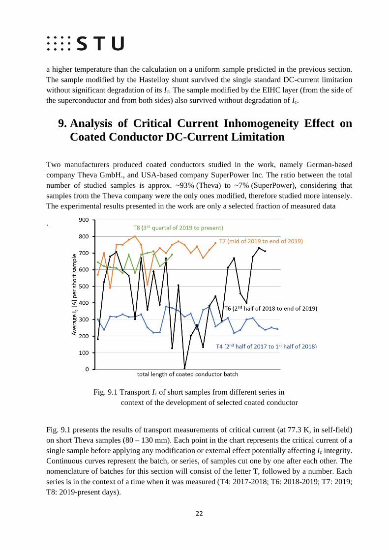
Fig. 9.1 Transport Ic of short samples from different series in
context of the development of selected coated conductor
Fig. 9.1 presents the results of transport measurements of critical current (at 77.3 K, in self-field)
on short Theva samples (80 – 130 mm). Each point in the chart represents the critical current of a
single sample before applying any modification or external effect potentially affecting Ic integrity.
Continuous curves represent the batch, or series, of samples cut one by one after each other. The
nomenclature of batches for this section will consist of the letter T, followed by a number. Each
series is in the context of a time when it was measured (T4: 2017-2018; T6: 2018-2019; T7: 2019;
T8: 2019-present days).

23
Table II.: The critical current deviation of different CC series
Table II. shows standard deviations of selected data series from Fig. 9.1. The critical current
deviation in T6, from which the largest number of samples was studied, is 250% higher compared
to newer T7, and almost 500% higher compared to the latest T8. Therefore, we conclude
significant improvement in the overall Ic homogeneity of later developed coated conductors.
However, it should be emphasized that the curves represent the average transport Ic measured
along the ~100 mm length. The possible incidence of local Ic inhomogeneities along the lengths
shorter than 100 mm samples is not investigated in these experiments.
Let us compare the effectiveness of the EIHC modification on the presented series. The standard
modification is by Stycast with SiC filler. However, the SiC ratio differs (10-25%) not only
between series but also samples from the same series have slightly different filler ratios. The
thickness of the EIHC can vary even on a single sample, because of the early stage method for the
EIHC layer application. Therefore, it is not a simple task to rigorously quantify and compare the
performance of the EIHC over years (progress in the EIHC application, experimental testing
procedures, etc.). However, the samples presented below were tested at the standard experimental
condition e.g. the electric field criterion of 120 Vm-1 of DC-current limitation for 50 ms at 77.3 K
(self-field):
Table III. summarizes success rate of EIHC modification at "standard" experimental
conditions. Even when the presented samples were not modified by the identical layers (different
filler ratio, non-uniformity of EIHC thickness), the statistics indicate a success rate trend.
Table III.: The success rate of EIHC modification
The early "relatively homogeneous, low Ic" series (T4) showed a positive trend of EIHC
modification. The later "highly non-homogeneous, high Ic" series (T6) proved in numerous
specified experiments (also various other experiments, which are not included in statistics but are
worth mentioning) as irregular and its results unrepeatable. Therefore, the EIHC modification was
insufficient in specified fault current conditions. Even samples modified by similar modification
Sample series The standard Ic deviation
σstd = √∑(𝑥𝑖−𝑥𝑚𝑒𝑎𝑛)2
𝑛−1𝑛𝑖=1
Statistical set (n)
T4 46.8 29
T6 209.4 28
T7 85.2 19
T8 45.8 13
Sample series Reference sample Success rate
(120 Vm-1 for 50 ms at 77.3 K)
T4 degraded (0.46*Ic) 80 %
T6 completely degraded < 50%
T7 completely degraded without conclusion
T8 degraded (0.3*Ic) 100 %

24
and with very similar average Ic behaved differently. The last samples, "relatively homogeneous
with high Ic" proved the effectiveness of EIHC modification in specified experimental conditions.
10. Local Quench Observed via High-Speed
Fluorescent Optical Imagining
The previous statistical results showed positive effect of EIHC modification on
inhomogeneous samples. In this section is investigated the effect of artificially created local critical
current minimum to observe dynamics of localized quench. The quench is observed via high speed
camera able to record fluorescent light excited on the surface of coated conductor through
temperature change. We compare the reference sample, sample modified by the EIHC layer form
the side of superconductor and sample modified by EIHC layer from the side of substrate. The
experimental method is sufficiently described in [97].
Fig. xx shows illustration of experimental apparatus.
Fig. 10.1 Illustration of measurement setup for quench
evolution observation via high-speed camera [97]
Sample Preparation
The section presents three samples with the same standard architecture; a 12 mm wide Theva
sample with a 3 µm thick superconductor. The reference sample is coated only by a 2 µm silver
overlayer, with no modification. We additionally modified the second presented sample with the
EIHC layer from the side of the HTS. We also coated the third sample with the EIHC layer but
from the side of the Hastelloy substrate ("bottom"). The length of the sample is ~70 mm. A 20 mm
copper layer coated the sample endings for current leads. We coated the sample surface from the
side of the superconductor with a thermally excitable fluorescent layer – a mixture of the

25
fluorophore, europium tris (3-(trifluoromethylhydroxymethylene)), and camphorate (EuTFC). The
layer serves as an optical indication for NZPV observation. The thermal sensitivity of such coating
ranges from 77.3 K to 260 K [97]. The coating was solidified on the sample surface by drying in
the oven for two hours at ~90 ̊C.
Fig. 10.2 Sample holder for high-speed camera quench recording, (a.) Reference sample
with no additional coating or copper stabilization, (b.) sample coated with the EIHC from
the side of superconductor, and (c.) sample coated with the EIHC from the side of the
Hastelloy substrate (the EIHC layer is not visible).
Results:
Reference sample:

26
Sample modified by the EIHC layer:
Fig. 10.3 Comparison of the refereence and the EIHC modified sample
To conclude, the results from experiments presented in the section: the EIHC layer causes
approximately two times lower normal zone propagation velocity compared to the reference
sample with only a silver overlayer. However, as was shown in the experiment with only the EIHC
modification from the superconductor side, the quenched area is 10 to 20 times larger compared
to the reference sample. That reduces the density of dissipated energy and at the same time, it
increases the heat transfer area to the LN2. In the experiment with the EIHC layer applied from the
side of the substrate, we observed a reduction in NZPV comparable to the EIHC applied from the
HTS side, however, the normal zone area is larger two to four times compared to the reference.
Here we have to consider the asymmetry of the coated conductor cross-section. The substrate has
a major role in the heat transfer, therefore it limits the effectiveness of the EIHC layer (on the
substrate side) on heat dissipation from the superconductor layer.
The critical current of the reference sample significantly degraded after the first quench at
680 A for 12 ms. CC modified by the EIHC layer from the HTS side survived several times longer
duration of pulses with no degradation of Ic. The sample modified by EIHC from the substrate side
showed degradation of silver overlayer from HTS side but no significant degradation of Ic even
after several quenches. The EIHC layer therefore up to some degree enhances coated conductor
resilience against the formation of a hotspot.

27
11. The Effect of Current Rate on Coated Conductor
Degradation During DC-Current Limitation
The section investigates the dynamic character of the coated conductor quench induced by the DC-
current limitation experiment. The subsequent section focuses on the effect of DC pulse rate on
the degradation of critical current. It also studies the effect of reduction of the ambient temperature
to increase the superconductor current-carrying capacity of the CC. Such temperature reduction
can increase the critical current of the CC more than two times. In the subsection is further studied
the effect of the current rate on the sample degradation.
Fig. 11.1 Significant Ic degradation during the DC-current limitation at lower temperature [18]
However, was shown recently in [18], the reduction of ambient temperature can lead to coated
conductor degradation at the identical DC-current limitation conditions. Fig. 11.1 shows sudden Ic
degradation on a single 6 mm wide sample. The DC-current limitation experiment begins at
77.3 K. The critical current of the coated conductor was measured before and after each
DC-current limitation experiment. At the temperature of 66 K, rapid degradation of
superconductor critical current during the DC-current limitation occurred.
Table IV.: Circuit parameters and initial current ramp rates [18]
We experiment with alternation of current ramp rate to investigate possibility to prevent critical
current degradation. To investigate this, we present two experiments with different current ramp
rates. Let us call experiment with higher current ramp rate Experiment A. Then the current pulse
rate was artificially reduced by increasing circuit inductance (Experiment B). The coated
conductor from the same series as in Experiment A was chosen, with a similar average Ic and n-
Circuit Inductance [µH] Initial Current Ramp Rate [As-1]
Experiment A 3 5000
Experiment B 6 2500

28
factor. The current limitation parameters are the same as data from Experiment A, the initial
ambient temperature was set to 66 K. The only difference is the rate of the current pulse. The I-V
of the sample in Experiment B with lowered current ramp rate did not change, therefore its critical
current did not degrade..
Fig. 11.2 Experimental and calculated evolution of current at a different rate [18]
The results of a numerical calculation in Fig. 11.3 shows temperature development in a uniform
sample calculated for conditions corresponding to Experiment A and Experiment B. The results
of calculations suggest two important phenomena possibly causing a significant difference of
coated conductors DC-current limitation performance in Experiment A and Experiment B. The
first observation is that the temperature rise with a lower current rate is slower in Calculation B
compared to Calculation A. The transition to a normal state has less stepper character with a lower
current rate. The second important observation is the initial ambient temperature dependence of
the temperature generated by Joule heating. At 66 K, the temperature development in the CC at
66 K is steeper compared to 77 K for the identical sample under identical current limitation
conditions.
The overal conclusion of the research is that the current rate of the DC-current pulse has
a significant effect on the coated conductor's ability to dissipate generated heat during the quench.
The initial ambient temperature affects the temperature evolution during the current limitation
experiment and can lead to critical current degradation because of higher temperature rise rate
during DC current limitation at lower temperature.

29
Fig. 10.3 Temperature evolution in superconductor layer at
different ambient temperatures for various current rates
The quench study in local Ic inhomogeneity inherited from the fabrication:
In previous section we observe the effect of the current rate on the coated conductor during DC-
current limitation. The section presents the performance of unmodified REBCO CC during the
DC-current limitation experiment and the effect on regions with the lower critical current
originated during its fabrication.
Fig. 10.4 Illustration of 6 mm sample cross-section (not in scale)
The 6 mm wide (SuperPower) sample is selected based on our previous experience with its
relatively low Ic longitudinal inhomogeneity, compared to the T6 Theva series. The average critical
current is ~150 A. The Hastelloy substrate is 50 µm thick. A 2 µm thick silver overlayer covers
from all sides the superconductor and substrate.

30
Fig. 10.5 Illustration of Ic_min position identified by DC-pulse characterization
(not in scale)
The length of regions closer to the current leads (L1, L5) is 200 mm, and inner regions (L2, L3, L4)
are 160 mm long. After we installed the sample into the sample holder and cryostat, we measured
the Ic of selected regions.
The characterization identifies the 2nd region as weakest at both temperatures. The 1st region
is the second weakest. The lowest critical current, together with the highest resistance in a normal
state causes the steepest rise of the electric field in the 2nd region.
Fig. 10.6 Longitudinal Ic homogeneity in static and pulse characterization and
resistance at room temperature
After the initial sample characterization, the DC-current limitation experiment was conducted. The
ambient temperature of LN2 in DC-current limitation experiments is 66.0 K. Experiment was done
at 10 ms up to 120 Vm-1. The aim is to observe regions with lower Ic during the DC-current
limitation experiment and the effect of the current pulse at current different rates. The change of
the current rate is done by adjustment of circuit inductance Higher circuit inductance causes a

31
lower current rate. The circuit inductance is also used to represent the difference in the current
pulse slope.
The experimental procedure: The voltage of the power supply is constant. The set of DC limitation
experiments is iterative. The experiment begins at pulses with amplitude lower than Ic. At constant
current amplitude, we changed the slope of the current pulse from lower to higher. After each
DC-current limitation, the sample I-V was tested. We chose this approach because of previous
experience with fast current change causing damage to the CC. We increased the current
magnitude and rate until the first quench of the sample. In Fig. 10.7 a.) there is current evolution
in the sample. The black curve represents the last current magnitude when the sample did not
quench and the current was not limited by the CC. The 6 µH circuit inductance represents a current
rate of ~2500 As-1. Then we increased the current pulse rate to 5000 As-1 (3 µH). There is a higher
current in the second and third DC-current limitation compared to the first pulse. We cannot,
therefore, completely rule out the quench initiated by the higher current magnitude. However, the
effect of a current rate can be still observed during the quench.
Fig. 10.7 a.) Current evolution, b.) Electric field-time evolution

32
Fig. 10.7 b.) shows the electric field in the two quenched regions. The maximum electric
field along the sample was set to be 120 Vm-1, in case of uniform transition along the sample.
However, the local electric field in region 2 is almost two times higher. The “hotspot” has higher
electric fields, which leads to higher energy dissipation in the region. The electric field of ~220
Vm-1 in region 2 was reached in 10 ms pulse. In a standard 50 ms experiment, it would be higher.
The density of dissipated energy in the sample is higher due to local inhomogeneity.
Fig. 10.8 a.) presents the I-E dependence of regions 1 and 2. Region 2 reached a complete
quench along. The measurement closely demonstrates normal zone propagation from region 2 to
region 1. At first, region 1 did not quench because it was limited by region 2. However, because
resistive losses are dissipating in region 2, heat propagates to region 1 and causes a complete
quench in region 1. Heat evolution originating in region 2 causes the initial slow rise of the electric
field in region 1. When the heat propagates through the whole width of the superconductor, there
is a complete phase transition in region 1. From electric field evolution in region 1, we estimated
the NZPV of this particular 6 mm sample without any modification to be ~3 ms-1.
.
Fig.
10.8 The log-log scale of quench in regions 1 and 2 at two circuit inductances

33
Fig. 10.8 b.) shows region 2 measured at two different circuit inductances (current rates). Here
we evaluate the change in the n factor of superconductor transition to normal state. We see that
at a higher current rise rate (3 µH or 5000 As-1), there are two times higher n factor compared to
6 µH (2500 As-1). The difference in current rate change, achieved by variation of circuit
inductance shows, that higher current rate change affects the n-factor of the transition. At 5000
As-1 (3 µH), the measured n-factor of transition is 96, while in the experiment with 2500 As-1 (6
µH) the
Fig. 10.9 Location of degraded points in the region 1 and 2.
n-factor is 48. The temperature dependence of the n factor is well known [20], [21], [19] The
higher n-factor during the transition suggests higher temperature dissipated in the experiment with
a higher pulse current rate.
The two measurements presented in Fig. 10.8 are only two representants out of a total of 34 DC-
current limitation experiments done on the sample. The results repeated even after partial
degradation of the critical current. After the experiment, we observed the exact location of two
hotspots causing quench in regions 2,1. It is visible to the naked eye. Fig. 10.9 shows the location
on two burned points (of approximately circular shape) on top of the silver overlayer.
To conclude the presented experiment: we showed in a controlled environment the effect
of two weaker regions originating in the coated conductor fabrication process in DC-current
limitation conditions. The experiment was done in a such manner, that the DC current pulse
34
induces the quench in only regions with the lowest critical current. In such conditions, the electric
field is concentrated in several times the smaller area than expected. It can lead to the degradation
of the critical current. At the same time, we showed the effect of the current rate change on a
smaller scale compared to section 10.1. We were able to observe the change of the n factor during
the transition to the normal state. The change in the n factor suggests the difference in the local
temperature of the quenched regions. Additionally, we were able to observe normal zone
propagation from region 2 to region 1 and confirm experimentally obtained velocities in section
9.2.3. We can therefore conclude that the current rate during the quench affects the temperature
dissipated in the region. The effect has more severe consequences in the case of local critical
current inhomogeneities, where it can lead to the density of dissipated energy is higher.

35
12. Conclusions
The thesis focuses on the investigation of 2G HTS superconducting conductor applicability
for DC-current limitation. The objectives derive from the aim to achieve the cost-effectiveness of
the coated conductors. To decrease the amount of the conductor, two potentially valid approaches
were investigated: enhancement of the coated conductor thermal stability to withstand higher
electric fields and increasing the current-carrying capacity to transport higher currents.
Throughout the solution of the thesis, the DC current pulse apparatus for short
(100-1000 mm) coated conductor electrical properties characterization (I-V dependence) was
developed and standardized for experimental evaluation of coated conductor samples.
Simultaneously with the characterization apparatus, the DC-current limitation experimental
apparatus with a constant voltage (CV) power supply was built. The DC-current limitation
experimental apparatus is used to investigate a short length (standardly ~100 mm, successfully
tested up to 700 mm) coated conductor performance during the current limitation in specified
conditions. Standard conditions for the DC-current limitation experiment utilized throughout
the thesis were 120 Vm-1 for 50 ms. The current limitation experimental apparatus can artificially
alter the current pulse rate. For a dynamic quench investigation, the high-speed camera recording
fluorescent light emitted from the surface of the coated conductor is utilized.
The numerical model of coated conductor for investigation of its DC-current limitation
performance was developed to complement experimental results. The model includes the
simulation of the circuitry for a closer approximation of experimental conditions.
The work presents a novel approach to thermal stabilization of coated conductors for
R-SFCL application: Electrically insulating, high thermal capacity modification (EIHC).
Numerical and experimental methods investigate the concept.
- The electro-thermal numerical analysis of uniform coated conductors in the constant
voltage circuitry under the DC-current pulse (I > Iq) compares the performance of the
reference coated conductor, the coated conductor modified by a metallic shunt (stainless
steel, Hastelloy), and the coated conductor modified by the EIHC layer. The electro-
thermal numerical calculations show temperature reduction at the end of the 50 ms pulse
at 120 Vm-1 for all selected coated conductor enhancement methods.
- The DC-current limitation experimental results in section 7 show in some cases good
agreement with the numerical calculations on uniform samples. The experimental results
on ~100 mm samples have, however, very inconsistent repeatability. A direct correlation
between coated conductor critical current longitudinal homogeneity and degradation of the
coated conductor Ic during the DC-current limitation experiment is shown.
- The CC modified by the EIHC suggests that in samples with very high critical current
deviation (209.4), the critical current degradation occurs in more than 50% of cases (T6
series). In sample series (T4) with lower critical current deviation (46.8) and at lower
critical current magnitudes, the degradation occurs in 20% of samples. In samples
fabricated by the most advanced technique (T8), with the most homogeneous longitudinal
Ic distribution (45.8) and with the highest Ic magnitude, the degradation of critical current
was not observed at identical DC-current limitation conditions.

36
- The high-speed fluorescence imagining technique was used to observe the artificially
induced quench in the reference sample and the samples modified by the EIHC layer.
Despite slower normal zone velocity in the coated conductors modified by the EIHC layer,
the area of the normal zone in the sample modified by the EIHC layer is 10 - 20 times
larger compared to the reference sample. Heat dissipation in the larger area causes a more
uniform quench along the sample and enlarges the heat transfer area.
- At 66 K, a significant critical current degradation during the DC-current limitation
experiment was observed. With the support of the numerical modeling, we proposed the
explanation that at lower temperatures the longitudinal Ic inhomogeneity together with a
higher temperature rise rate results in a locally higher density of dissipated heat.
- The experiment with alternation of the current pulse rate during the DC-current limitation
showed, that a higher current rate affects the n factor of the superconductor during the
quench. It indirectly suggests that with a higher current rate there is a higher temperature
in the superconductor. As we showed, the alternation of the current ramp rate can prevent
the degradation of critical current. The effect of the current ramp rate is important
especially in CC with higher Ic longitudinal inhomogeneity with the possibility of localized
hotspots, where a higher current ramp rate increases the density of dissipated heat. The
results were published in a peer-reviewed journal.

37
13. List of Publications
Publications in CC database:
1. Mošať, M., Šouc, J., Vojenčiak, M., Solovyov, M., Búran, M., and Gömöry, F.: Influence of current change rate during DC current limitation on the coated conductor degradation IEEE Trans. Applied Supercond. 31 (2021) doi: 10.1109/TASC.2021.3068332. (IF 1.962)
2. Búran, M., Vojenčiak, M., Mošať, M., Ghabeli, A., Solovyov, M., Pekarčíková, M., Kopera, Ľ., and
Gömöry, F.: Impact of a REBCO coated conductor stabilization layer on the fault current limiting functionality, Supercond. Sci Technol. 32 (2019) 095008. (IF 2.489)
3. Pekarčíková, M., Mišík, J., Drienovsky, M., Krajčovič, J., Vojenčiak, M., Búran, M., Mošať, M., Húlan, T., Skarba, M., Cuninková, E., and Gömöry, F.: Composite heat sink material for superconducting tape in fault current limiter applications, Materials 13 (2020) 1832. (IF 3.057)
Publications in SCOPUS database:
1. Vojenčiak, M., Mošať, M., Pekarčíková, M., Michalcová, E., and Mišík, J.: Advanced
superconducting tapes for high voltage fault current limiters. In: 12th Inter. Conf. ELEKTRO 2018.
Eds. P. Hockicko et al. Piscataway: IEEE 2018. ISBN: 978-1-5386-4759-2, no. 93.
Attendance in international conferences
1. Mošať, M., Vojenčiak, M., Búran, M., Šouc, J., Pekarčíková, M., and Gömöry, F.: HTS coated conductor current limiting performance at temperatures lower than 77K. In: EUCAS 2019. Glasgow 2019. Výveska.
2. Mošať, M., Vojenčiak, M., Gömöry, F., Lacroix, C., and Sirois, F.: Importance of stabilization layer homogeneity for coated conductors used in fault current limiter. In: Workshop on Coated Conductors for Applications 2018. Vienna 2018. Výveska.
Co-author:
3. Gömöry, F., Mošať, M., Pardo, E., Vojenčiak, M., Lacroix, C., and Sirois, F.: Electro-thermal modelling for optimization of CC tape in DC fault current limiter. In: 6th Inter. Workshop on Numerical Modelling of High Temp. Supercond. Caparica 2018. Výveska.
4. Vojenčiak, M., Mošať, M., Buran, M., and Gömöry, F.: REBCO coated conductor for fault current limiter application in cryogen free conditions. In: Workshop on Coated Conductors for Applications 2018. Vienna 2018.
5. Pekarčíková, M., Cuninková, E., Mišík, J., Vojenčiak, M., Mošať, M., Skarba, M., Halanda, J., Necpal, M., and Gömöry, F.: Investigation of CC tapes with soldered metallic high heat capacity layer suitable for superconducting fault current limiters. In: Workshop on Coated Conductors for Applications 2018. Vienna 2018. Výveska.

38
6. Gömöry, F., Vojenčiak, M., Mošať, M., Pardo, E., Buran, M., Pekarčíková, M., Cuninková, E., Mišík, J., Bauer, M., Lacroix, C., and Sirois, F.: Improved quench robustness of CC tapes for FCL due to increased thermal capacity. In Applied Supercond. Conf. 2018. Seattle 2018.
7. Pekarčíková, M., Mišík, J., Skarba, M., Necpal, M., Vojenčiak, M., Mošať, M., and Gömöry, F.: Study of CC tapes damaged during fault current limitation at 66 K. In: EUCAS 2019. Glasgow 2019. Výveska.
8. Gömöry, F., Šouc, J., Vojenčiak, M., Mošať, M., Pekarčíková, M., Lacroix, C., and Sirois, F.: Hot spot creation in coated conductors used for fault current limitation. In: EUCAS 2019. Glasgow 2019.
9. Vojenčiak, M., Búran, M., Mošať, M., Pekarčíková, M., and Gömöry, F.: Additional stabilization of REBCO coated conductors for fault current limiters. In: EUCAS 2019. Glasgow 2019. Výveska.
Co-author in different topics in applied superconductivy:
10. Pardo, E., Dadhich, A., Li, S., Kapolka, M., Solovyov, M., Mošať, M., Kováč, J., and Šouc, J.: Modeling and measuring the cross field demagnetization of REBCO stacks and bulks for millions of cycles. In Applied Supercond. Conf. 2020 Virtual Conf. (organized in USA). Pozvaná.
11. Ries, R., Mošať, M., Gömöry, F., Vojenčiak, M., Seiler, E., Pekarčíková, M., Cuninková, E., and Mišík, J.: Characterizing of superconducting tape quality by measuring magnetic AC susceptibility. In: Workshop on Coated Conductors for Applications 2018. Vienna 2018. Výveska.
12. Mikulášová, E., Gömöry, F., Ries, R., Kujovič, T., Mošať, M., and Sojková, M.: Low temperature bonding of superconducting tapes covered by Ag layer. In: Workshop on Coated Conductors for Applications 2018. Vienna 2018. Výveska.
Citations: 6 (+ 2 autocitations)
Gömöry, F., Mošať, M., and Šouc, J.: Superconducting fault current limiter operating in liquid nitrogen. In:
ELEKTRO 2014. Žilina: FEE Univ. Žilina 2014. ISBN 978-1-4799-3721-9. P. 650-653.
1. Naji, H.: Energies 12 (2019) 3007.
Búran, M., Vojenčiak, M., Mošať, M., Ghabeli, A., Solovyov, M., Pekarčíková, M., Kopera, Ľ., and Gömöry, F.: Impact of a REBCO coated conductor stabilization layer on the fault current limiting functionality, Supercond. Sci Technol. 32 (2019) 095008.
1. Yuki, K.: Supercond. Sci Technol. 33 (2020) 034002.
2. Akbar, A.: Supercond. Sci Technol. 33 (2020) 115003.
3. Ye, J.: Ceram. Inter. 46 (2020) 21989.
4. Jiang, Z.: J. Phys. Comm. 5 (2021) 025003.
5. dos Santos, G.: Supercond. Sci Technol. 34 (2021) 025012.
6. Xu, Y.: J. Europ. Ceramic Soc 41 (2021) 480 .

39
14. References
[1] PAUL, W. et al. Fault Current Limiter Based on High Temperature
Superconductors - Different Concepts, Test Results, Simulations, Applications. In
Phys. C Supercond., 2001, vol. 354, no. 14, pp. 27 – 33, DOI: 10.1016/S0921-
4534(01)00018-1
[2] LU, J. et al. Oxygen out-diffusion in REBCO coated conductor due to heating. In
Supercond. Sci. Technol., 2021, vol. 34, no. 7, DOI: 10.1088/1361-6668/abfd0c
[3] BÚRAN, M. et al. Impact of REBCO coated conductor stabilization layer on the
fault current limiting functionality. In Supercond. Sci. Technol., 2019, vol. 32, no.
9, DOI: 10.1088/1361-6668/ab2c8e
[4] BUSHONG S. Why the wind industry should cheer superconductivity", May
2012,[cit. 10. 5. 2021], [online]: https://www.windpowerengineering.com/why-
the-wind-industry-should-cheer-superconductivity/
[5] CHERPAK, Y. V. et al. Critical Current Density of HTS Single Crystal YBCO
Thin Films in Applied dc Field. IN IEEE TAS, 2005, vol. 15, no. 2, pp. 2783–
2786, DOI: 10.1109/TASC.2005.848212
[6] GUREVICH, A. To Use or Not to Use Cool Superconductors ? In Nature
materials, 2011, vol. 10, pp. 255–259, DOI: 10.1038/nmat2991
[7] SuperPower Inc. website - 2G HTS Wire Specification, Glenville, New York,
USA, [cit. 1. 6. 2021]
[8] LACROIX, C., SIROIS, F. Concept of current flow diverter for accelerating
normal zone propagation velocity in 2G HTS coated conductors. In Supercond.
Sci. Technol., 2014 , vol. 27, no. 3,
DOI: 10.1088/0953-2048/27/3/035003
[9] VLAD, R. et al. Materials Developement & Oxygenations: Oxolutia
Contributions (CFD) [Project meeting presentation]. 5th FastGrid Project Meeting,
Bratislava, Slovakia, 22nd November 2018. [cit. 21. 7. 2021]
[10] DEUTCHER, G., AZOULAY, M., SARAF, A. High Power Dissipation FCL
Elements – YBCO on sapphire [Project meeting presentation]. 5th FastGrid
Project Meeting, Bratislava, Slovakia. 22nd November 2018. [cit. 21. 7. 2021]
[11] DEUTSCHER, G. High-Voltage Superconducting Fault Current Limiters Based
on Hight-Difusivity Dielectric Substrates. In Journal of Superconductivity and
Novel Magnetism, 2018, vol. 31, pp. 1961–1963, DOI: 10.1007/s10948-018-4633-
8

40
[12] SARAF, A. et al. Sapphire-Based SFCL Conductors in Superconducting Fault
Current Limiter. Singapore: World Publishing, 2018, pp. 357-372
[13] Collective of authors from MolTech GmbH. Sapphire (Al2O3), [cit. 21. 7. 2021],
[online:] http://www.mt-berlin.com/frames_cryst/descriptions/sapphire.htm
[14] TAKASHIMA, H., ICHI SASAKI, K., ONISHI, T. Thermal stress analysis for
the meander-shape YBCO fault current limiter. In Phys. C Supercond., 2004, vol.
411, no. 1, pp. 25–31, DOI : 10.1016/j.physc.2004.03.248
[15] PEKARČÍKOVÁ, M. et al. Composite Heat Sink Material for Superconducting
Tape in Fault Current Limiter Application. In Materials, 2020, vol. 13, no. 8,
pp. 1832, DOI: 10.3390/ma13081832
[16] PEKARČÍKOVÁ, M. et al. Composite Heat Sink Material for Superconducting
Tape in Fault Current Limiter Applications. In Materials, 2020, vol. 13, no. 8, pp.
1832, DOI: 10.3390/ma13081832
[17] LACROIX, C., SIROIS, F.Impact of Current Flow Diverter on Innovative HTS
Tape Architectures for DC Fault Current Limitation at Electric Field up to
150 V/m. In IEEE TAS., 2019, vol. 29, no. 5, DOI: 10.1109/TASC.2019.2908599
[18] MOŠAŤ, M. et al. Influence of Current Change Rate During DC Current
Limitation on the Coated Conductor Degradation. In IEEE TAS, 2021, vol. 31,
no. 5,
DOI: 10.1109/TASC.2021.3068332
[19] GÖMÖRY, F., ŠOUC, J. Stability of DC transport in HTS conductor with local
critical current reduction. In Supercond. Sci. Technol, 2021, vol. 34, pp. 20,
DOI: 10.1088/1361-6668/abc73e
[20] MAZA, J. et al. Transition to the normal state induced by high current densities in
YBa2Cu3O7-δ thin films: A thermal runaway account. In Phys. Rev. B, 2008, vol.
78, no.9, DOI: 10.1103/PhysRevB.78.094512
[21] VIñA, J. et al. Self-heating effects on transition to a highly dissipative state at
high current density in superconducting YBa2Cu3O7-δ thin films. In Phys. Rev. B,
2003, vol. 68, no.22, DOI: 10.1103/PhysRevB.68.22450
Copyright © 2022 FDOKUMEN