Concept House Facade - TU Delft Repositories
141
►► Concept House Facade P5_Thesis Report Integration of ceramics and loam in prefabricated facade panels title: Integration of ceramics and loam in prefabricated façade panels department: Building Technology – Architecture Faculty / TU Delft track: International Facade Master student: Isaia Savvidou 1st mentor: Arie Bergsma Faculty of Architecture, Building Technology 2nd mentor: Arjan van Timmeren Faculty of Architecture, Building Technology external evaluator: Hans Wamelink Faculty of Architecture, Real Estate date: 05 - 11 - 2010
-
Upload
khangminh22 -
Category
Documents
-
view
1 -
download
0
Transcript of Concept House Facade - TU Delft Repositories

►► Concept House Facade P5_Thesis Report
Integration of ceramics and loam in prefabricated facade panels title: Integration of ceramics and loam in prefabricated façade panels department: Building Technology – Architecture Faculty / TU Delft track: International Facade Master student: Isaia Savvidou 1st mentor: Arie Bergsma Faculty of Architecture, Building Technology 2nd mentor: Arjan van Timmeren Faculty of Architecture, Building Technology external evaluator: Hans Wamelink Faculty of Architecture, Real Estate date: 05 - 11 - 2010
2
► Index
►Abstract _5
1. Introduction_6
1.1 Topic_7 Main principles of the Concept House 1.2 Motivation_8 Earth & Sustainability Earth & Dwellings Earth & the Dutch climate 1.3 Hypothesis_9 Research question Sub - question
2. Literature Study_11
2.1 Façade Design_12 2.2 Climate and Location_13 Climate Location Bricks in the Netherlands Materials and location Earth bricks Fired bricks Skepticism 2.3 Building physics_17 2.3.1 Heat_17 2.3.2 Moisture_19 Relative humidity Condensation 2.4 Passive solar design_22 Thermal mass and passive design Thermal mass in the Dutch climate Orientation of thermal mass and openings Coverings – carpets / tiles – colors – textures Thermal mass in winter Thermal mass in summer 2.5 Active heating and cooling systems_25 Thermo active building systems Different types of TABS Working principle Energy consumption Energy sources 2.6 Loam_29 2.6.1 Composition of loam_29 2.6.2 Properties of loam as a building material_30 Effects of water Effects of humidity Influence of heat

3
2.6.3 Production of loam_33 Compressed earth blocks Extruded earth slabs and blocks 2.6.4 Integration of loam into building constructions_36 Function Geometry of components 2.7 Ceramics_39 2.7.1 Composition of ceramics_39 2.7.2 Properties of ceramics as a building material_39 Resistance to the exterior environment Mechanical properties 2.7.3 Production of ceramics_41 Forming methods Surface treatment 2.7.4 Integration of ceramics into building constructions_43 Systems
3. Method_45
3.1 Standard systems – analysis & comparison_46 3.1.1 Insulated cavity wall_46 Advantages Disadvantages 3.1.2 Insulated timber frame panels_48 Advantages Disadvantages 3.1.3 Evaluation – targets for new system_49 3.2 The model_50 3.2.1 Functions and components_50 Layers of the facade Façade system and components 3.2.2 Inner layer: water circulation for heating and cooling_52 Indoor climate and performance Pumps and water distribution Control Materials Drilling Choice 3.2.3 Integration of water pipes into loam_55 Modular approach Integral approach Proposal 3.2.4 Outer layer: water circulation for solar collection and cool_60 Reference model Ideas Solar collection Cool Summer situation Winter situation 3.3 Hand calculations and computational tools_65 3.3.1 Design Parameters_65 Dimensions – shading elements Function References Room Temperatures Internal heat load Ventilation fold 3.3.2 Hand Calculations_68

4
Heat Resistance and U values Winter situation - heating Summer situation - cooling Pump energy 3.3.3 CAPSOL - Input_72 Input – winter model Input – summer model 3.3.4 CAPSOL - Calculations_77 Winter situation Summer situation Summary - comments
4. Design_89
4.1 Plans and structure_90 4.2 Openings and sun shading_92 Openings Sun shading Openings and sun shading for the concept house 4.3 Timber frame_97 Timber frame façade panels for the Concept House 4.4 Integration – inner layer_100 4.5 Integration – outer layer_103 Water supply and installation of pipes behind the façade Alternative systems for the integration of copper pipes into ceramic panels Possible solutions for the Concept House Proposal 4.6 Construction and support to the structure_111 Proposal for the support to the structure Connections along the height of the panel Drawings
5. Results and Discussion_117
5.1 Evaluation of the results_118 Hypothesis and method 5.2 Suggestions for further research_122
6. Conclusions_123
►Acknowledgements _124 ►Literature _125 ►Appendix _127

5
► Abstract The sustainable solution of a prefabricated façade system with timber frame panels was the issue of this thesis. The choice of materials was one of the tasks. The use of loam and ceramics in the façade panels were examined as an improvement of the indoor climate while minimizing the energy consumption for the system demands. The application of the materials in a façade system in the Dutch climate led to the study of the thermo active building systems (TABS) in the inner layer. The comparison with standard systems and tests of the model by hand calculations and computational tools - CAPSOL gave a better view of the performance of the system and suggestions for improvements. Prefabrication was analyzed at the case study of the Concept House with suggestions for the design of the components and ways of attaching the panel to the construction. Key words: prefabrication, loam, ceramics, TABS, timber frame façade panels

6
1. Introduction The current paper aims to present the final report of the graduation project at the International Facade Master, in Building Technology in the faculty of Architecture, TU Delft. The project regards the design of a prefabricated facade system for dwellings in the Netherlands, based on the principles of sustainability. The design of this facade system is a part of the project “Concept House”, a research program which started in 2007 and is still on progress. The Concept House project will lead to a first prototype of an innovative house in the beginning of 2011 and will be a basis for the Concept House Village to be realized in Rotterdam in 2012. Input has been given by the main researchers of the Concept House, Joris Veerman, Rutger Wirtz and Jaap van Kemenade. The general focus of the research and design of this thesis is the improvement of the standard systems that are used at the moment in the Netherlands, with the integration of ceramics and loam as alternative building materials in a prefabricated facade system and the design of its components. This proposal will be elaborated from an environmentally friendly approach.

7
1.1 Topic The main task of the topic concerns the design of a facade system for dwellings in the Dutch climate that is prefabricated and takes sustainability as the main principle to guide all aspects of the research and design. Many stages of the design like the plans, the choice of materials, the main structure and the arrangement of the house units have already been completed within the Concept House research project. This will form the starting point of the proposed improved design for the façade system presented here. The guidelines, restrictions and decisions comprise the basic frame for the design of the facade system but the main focus and the way of approach are fr ee to be determined by the student as part of the graduation program.
1.1 3D explosion view of a unit and different arrangements of the house units Concept House brochure
Main principles of the Concept House Sustainability is a leading principle of the project and affects all decisions of the design from the scale of the single apartments to the materialization, the details and its systems and components. Besides of sustainability two more aspects are leading: industrialization and low cost housing in higher densities than average in the Netherlands. This is the main principle of the Concept House which also involves the main principles for the design of the facade system. Some of the main requirements: • choice of the materials: The choice of the materials is important for the toxic emissions that are released during production, the embodied energy (energy required for the production of the material) the recyclability and whether this is advantageous, the U-value and the performance of the materials in the building system. • smart fixings: Smart fixings concern interfaces between different layers, materials and components. They reduce energy, time and material waste during production. • prefabricated elements: Prefabricated elements are produced with more precision and accuracy under better conditions and reduce the working time on site that contributes to the concept of

8
sustainability by means of less damage due to weather influences and higher accuracy of fixings. Sustainability as an umbrella covers all aspects of design and all prospects in relation to time. Towards this target the concept of the “zero energy house” is something that will pay off in time and sustain the overall durability. In this context the design of the system which would consume as less energy as possible, would need less maintenance and would be friendly to the user is desired. The façade system has to take into account the characteristics mentioned above and integrate successfully all the components in the element façade panels. The main tasks to be completed for the design of the façade for the Concept House are summarized here:
1. The overall approach which should be environmentally friendly 2. The choice of the materials and the main focus 3. The design of a system for the Concept House facade 4. The integration of its components into the case study of the Concept
House
1.2 Motivation The given assignment from the Concept House already comprised a frame in which the design of the façade system should form. The overall approach is one of the tasks to be completed. The approach of this research started from the focus on the use of a (100%) natural material, in other words earth. Earth as a building material is used in its baked (ceramics) and unbaked form (loam). The first stimulant for the choice of this material came from the concept of the topic and some links attached to the main essence of the basic keywords:
_sustainability – nature, non-toxic, environmental friendly _housing – traditional
values, sense of intimacy, cozy feeling _location - climate: the Netherlands –
bricks, ceramics broadly used, corrosion resistant. The second stimulant came from my personal interest into the material and my attendance at a ceramic course at the current semester. That activity led me to the Dutch Design Week in Eindhoven and the exhibition “Ceramics & Architecture”. That boosted my interest into the topic and designated my decision. Earth & Sustainability Earth has been used as a building material for thousands of years almost in all parts of the world. According to the way of production, earth can have different properties that determine its use in the construction layers. The most widespread form of earth as a construction material is the block. Block has been used as sun-dried - adobe or fired. The firing of earth blocks is a process that changes in an irreversible way the properties of the material. In contrast the sun dried bricks when soaked in water return to their primal state. Thus earth can be used as backed or unbaked blocks. Both baked (ceramics) and unbaked (loam) blocks or adobes have special properties that can be utilized for different purposes in the construction. Another difference is in the energy demands during their production and the toxic emissions that are released during their production, the recyclability and reusability of their components. During the study of the properties of loam and its behavior from a building physics point of view, more attractive characteristics are presented with many prospects for

9
integration into a facade system. For the inside climate loam has a good thermal mass and can balance the levels of humidity. For the outside ceramics do not erode and protect from overheating. Its porous structure allows the material to breathe through the capillary action and cool the interior. Those features can contribute to the design of an efficient passive system that would reduce the needs of energy for heating and cooling. The sustainable nature of earth makes it an attractive material. Earth is used to be found in vernacular architecture and in general traditional systems. The transition from the traditional to the fully prefabricated systems is worth while to be explored. Earth & Dwellings Because of its background brick took a symbolic meaning as a natural and trusty building material. Its extended use and the fact that it is a natural material that originates directly from the subsoil, gives to it a sense of intimacy which is often appreciated in dwellings. For many years architecture was made without architects. People would build their own houses with available materials. The availability of earth in most parts of the world made it a very common material for the construction of houses. Earth & the Dutch climate In temperate climates like the Dutch, when the outside temperature is below zero the higher difference in degree of incoming fresh air and its exchange may make indoor air so dry that it may result in negative health effects. Earth, used on the inside layer of the façade can contribute into balancing the humidity inside. Ceramics on the other hand are used extensively in the facades in the Netherlands. The non-corrosive properties make them appropriate for resisting in rainwater.
1.3 Hypothesis A material by itself cannot make a system efficient and energy saving. A combination of different components, systems and functions can give the desirable result. Earth is studied in both its structure, baked and unbaked (loam and ceramic). The properties of the material are evaluated for its position in the possible layers of the facade. The design of a façade system is directly linked to the locat ion and the climate. A short review of the main characteristics on the Dutch climate show the main demands on the design of the façade system. The climate is temperate with an average winter temperature around 3.7°C and average summer temperature around 17°C. The relative humidity is around 87 and 67% respectively for winter and summer and the monthly precipitat ion around 64mm. The demands that should be fulfilled by the design of the façade system are: heating, regulating the relative humidity and protecting the outer layer from corrosion. Earth in the Dutch climate can be used best in the baked form on the o utside layer for its corrosion resistant characteristics and unbaked (natural) at the internal layer of the façade for it will help regulate humidity and store heat in its mass. The heating demand which is the most energy consuming cannot be covered just b y passive means of solar design because the heating demands in the Netherlands are high and the solar radiation does not heat sufficiently the thermal mass since the clearness is at 30% during winter. In arid climates with big differences in the temperature between day and night, earth is used in unbaked form to regulate indoor climate taking the advantage of its big

10
thermal mass. Since earth is not appropriate for this type of application in the Dutch climate thermo active building systems (TABS) were s tudied in order to add this property to the structure. In cloudy days where the sun radiation cannot warm up the interior of a room and the big thermal mass of earth cannot be taken as an advantage, thermo active building systems with the circulation of wa rm water as means of heat transfer in the mass of the earth can be used. Loam can also regulate the levels of relative humidity indoors. Those special characteristics of loam can be used at the inner layer to improve the indoor climate. Ceramics on the other hand with their properties of corrosion resistance can be used at the outer layer as a durable material that withstands in an environment with high levels of precipitation and humidity. The thermal mass of the material can be used as a host for water circulation that would collect heat during summer and generate energy. The performance of a façade system can be improved with a combination of the appropriate materials and the contribution of active and passive solar techniques. The proposal can contribute to a durable façade system which would contribute to the concept of the “zero energy house”. The research will focus on the inner layer and the improvement of the indoor climate, which will be tested. The outer layer will be proposed as concept prop osal. For both layers, integration into the Concept House façade will be proposed. For the integration of the element façade in the Concept House fcs timber frame panels are used. The choice was proposed by the Concept house team for its lower environmental impact and better energy performance. Timber frame panels are used extensively in the Netherlands and are one of the optional building systems used in prefabricated houses at the moment. Based on this hypothesis the research question is posed: Research Question
How can earth be integrated optimally into the prefabricated facade system of the Concept House with timber frame panels that uses the principles of sustainability and improves the indoor climate and overall durability? Sub-Questions
1. What is the shape and thickness of each layer in the facade system (ceramics, loam, insulation) that regulates the levels of relative humidity and provides sufficient heat protection, preventing condensation and reducing mechanical support for heating and cooling?
2. How can loam and ceramics be integrated into prefabricated panels made of timber frame?
3. How can the design of the facade be simple with optimized components to
create maximum flexibility?
4. Which are the techniques to joint ceramics and loam with o ther materials for the production of prefabricated components? How can these joints allow the detachment of the ceramic elements for reuse and loam for recycle?

11
2. Literature Study The purpose of this study was to focus on the important points of lite rature that help the writer and the reader understand the content and the frame in which the decisions and method for the approach of the design were made. The theoretical base from the literature study was used for the design of the system and its integration into the Concept House project. The façade performs as the protective cover of the building from the outdoor environment. The climate and location determine the outdoor conditions that formulate the design of the façade. In the general context of sustainability that the Concept House is based, the literature study focuses on the building physics, the passive systems and the contribution of active systems that provide thermal comfort indoors while targeting to the minimum energy consumption. The mater ial, earth, (in its two structures, ceramics and loam) that was chosen in this direction, was studied closely about its composition, properties and production techniques. Case studies gave examples of integration of the material into the element facade.

12
2.1 Façade Design The façade as a skin, an envelope for the building protects the interior from the outdoor environment and provides levels of comfort to the interior. The levels of comfort are estimated according to the majority of the people that define a situation in an indoor environment comfortable and those results derive from surveys and researches that have been made. In general the façade should provide thermal, acoustic and visual comfort. The façade as a part of the building can have some adaptive functions like heating, cooling, ventilation, light and sun protection.
2.1.1 main functions of the façade 2.1.2 adaptive functions on the façade with examples of components (Knaack, Klein, Bilow and Auer, 2007)
The design of the façade for the Concept House is focusing on the thermal comfort. The adaptive functions on the façade that are examined are the heating and cooling functions.

13
2.2 Climate and Location Since the skin of a building should protect the indoor environment from the outdoor environment, the first aspect that is taken into account in the façade design is the climate. The location reveals information about the microclimate, the soil and the available materials of the region. Climate The climate is temperate west coast with an average winter temperature of just above 0°C and an average summer temperature of 16°C. The average annual rainfall measures 760mm and the relative humidity amount to 89 p ercent in January and 81 percent in July. The average wind force is 4 on the Beaufort scale (Oliver, 1997). 2.2.1 graph with information about the climate 2.2.2 solar energy and surface meteorology, Amsterdam (climatetemp.info) (gaisma.com)
2.2.3 temperatures during the whole year in the Netherlands (CAPSOL software)

14
Location The Netherlands is located to the region of Lowlands. The term “Lowlands” applies as it has done for many years to the extreme northwest of the plain as it meets the North Sea. A region which was shaped by glaciation it has rich alluvial soils and areas of gravel and sandy soils (Oliver, 1997). The Netherlands are situated between longitudes 2°E and 8°E and between latitudes 50°N and 54°N. Many rivers run through the country and discharge into the North Sea. The river area consists of fossil sandy stream ridges and fossil flood basins of heavy clay. 2.2.4 map of the Netherlands showing the canals and rivers (worldcanals.com)
Bricks in the Netherlands The process of making bricks was imported in the 12
th and 13
th century from Italy,
initially into areas where clay was present and where the economy made the use of the new material possible. In comparison with Italy the Dutch clay was less suitable for brick making and this may be the reason why in the beginning the Dutch bricks were smaller than the Italians. The bricks where originally made in an open -ended kiln in the yard. The use of bricks extended in the country and by 1900 it was dominant (Oliver, 1997).
2.2.5 house in Amsterdam with bricks on the façade (personal file) The extensive use of bricks in the Netherlands is related to the availability of clay in the soil and the climate. For the high levels of precipitation a water and corrosion resistant exterior layer like bricks was an efficient solution.

15
Materials and location
In the vernacular architecture the use of every material is linked direc tly to the available sources on each region and the climate conditions. Earth has been used as a building material very extensively in all over the world, because of its availability in large quantities and its ease in manipulation and forming in desirable shapes. Sun-dried brick, plasters and limewash are some examples of this material used in vernacular architecture. Fired bricks although being used for thousands of years they were not that broad in use, since they are more difficult to produce (Vellinga, 2006).
Clay, the source for building with earth is found in delta areas. In the Netherlands, which is located in a region with many rivers running through it, the availability of the material makes its production suitable since brick production plants a re located directly next to the source.
2.2.6 Sun-dried brick diffusion
2.2.7 Used and manufactured: fire brick maps made from (Vellinga, 2006)

16
Earth bricks To refer in scientific terms earth when used raw as a building material, is often given the name loam. Loam is a mixture of clay, silt (very fine sand), sand, and occasionally larger aggregates such as gravel or stones (Minke, 2006). When speaking of handmade unbaked bricks, the terms ”mud bricks” or “adobes” are usually employed; when speaking of compressed unbaked bricks, the term ”soil blocks” is used. When compacted within a formwork, it is called “rammed earth” (Vellinga, 2006). Fired bricks Fired brick was initially introduced to Europe by the Romans. In other parts of the world was used in the Middle East by the Assyrians and Babylonians, in China during the Han dynasty. The earliest use was recorded in the Indus Valley in Pakistan 2500-2000 BC. By the eighteenth century fired brick has been an increasingly common vernacular building material through many parts of the world.
(Vellinga, 2006). Fire brick is an attractive material because of its durability and relative imperviousness, which make it particularly suited to areas with lots of wind and rain. Its resistance to fire makes it an attractive alternative to timber. A significant disadvantage in the production of bricks is that it is relative expensive, requiring specialized knowledge, labor and kilns and consuming large quant ities of fuel. Skepticism Thought promoted by many governments and international aid organizations, the production of fired brick is in decline in many parts of the world. Its non -renewable nature, rising fuel costs and the increased popularity of materials such as concrete and cement raise serious questions regarding the sustainability of fired brick in comparison to, for instance sun-dried brick (Vellinga, 2006) (see appendix A1).

17
2.3 Building physics This session presents some of the basics of building physics. This review is making more understandable the coming chapters which deal with the efficiency of passive systems and properties of earth as a building material. In temperate climates, people spend a big part of the day in enclosed spaces, so indoor climate is a crucial factor in well-being. Temperatures, humidity, pollution content of the air in a given room are some of the factors that regulate the sense of comfort in a space. The design of the facade can have a determin ative role in regulating those factors. The choice of loam as the material for the inner layer of the façade can improve the indoor climate.
2.3.1 Heat Sufficient insulation provides comfortable levels in the interior and saves big amounts of energy for heating. Heat flows from warmer to colder bodies through a medium. The degree to which heat is transferred depends on the speed of the flow of the transport medium and the difference in temperature between the object and the medium that is flowing. Heat can be transported though conduction, convection and radiation. Conduction: is the transfer of thermal energy between neighboring molecules in a substance due to a temperature gradient (wikipedia). Convection: is the transfer of thermal energy through the movement of molecules within fluids (i.e. liquids, gases and rheids). It cannot take place in solids (wikipedia). Radiation: describes any process in which energy travels through a medium or through space, ultimately to be absorbed by another body (wikipedia). A construction with good insulation should have a big heat resistance. To calculate the resistance, the heat conduction coefficient (λ) is necessary because it shows how much heat “flows” through a layer of material 1 meter thick, with a surface area 1m² and with temperature difference 1ºC. The unit of λ is W/mK. 2.3.1 Heat conduction coefficient of several materials. The greater λ is the easier the material can conduct heat
(Linden, 2006)
The heat resistance of a layer of a material (R) can be found by multiplying the reciprocal of (λ) with the thickness (d). It is important to calculate the heat resistance of a construction of air on air. Heat transfer takes place though radiation and convection. Convection depends on the speed flow over the surface which is much greater on the outside that the inside layer. The higher is the speed of air on the surface of a material the less is the heat resistance. To calculate the total heat transfer between inside and outside air, the heat transfer on the surface of the construction, both inside and outside has to be added. The heat transfer coefficient (α) should be expressed in terms of heat resistance: the heat transfer resistance r = 1/α (this information is used at the hand calculations see 3.3.2) .

18
The heat transmission coefficient U-value (W/m²K) is the opposite of heat resistance and of air on air and shows how much heat passes through a construction where there is a difference in temperature in 1ºC. The location of the insulation can also result in equable conditions indoors by the heat accumulation in the walls. The materials with high thermal mass accumulate more heat. 2.3.2 Location of the insulation. A lot of heat is stored in walls when t he insulation is on the outside
(Linden, 2006)
2.3.3,4,5 insulation to the outside layer, materials with big thermal capacity and reverse brick veneer (yourhome.gov.au) The thermal capacity (heat storage capacity) S of a material is defined as the product of specific heat (the amount of heat needed to warm 1 kg of a material by 1°C) c and density ρ (Sadobes=1300kJ/m³K see 2.6.2). S = cρ [kJ/m³K] The thermal heat capacity defines the amount of heat to warm 1 m³ of material by 1°C. The heat storage capacity Qs for a unit area of wall is S multiplied by the thickness of the element: Qs = cρs[kJ/m²K] The speed at which the material absorbs or releases heat is very important for the performance of the thermal mass. The speed is defined by the thermal diffusivity b which is dependent on the specific heat, density and conductivity. The larger the b-value, the quicker the penetration of heat (Minke, 2006). b = √cρλ[kJ/Κm²h½] A very thin layer would not store enough heat in its mass and a very thick l ayer would keep the heat in its mass and not releasing it to the interior. To give an estimation of the thicknesses, for the adobes a thickness of more than 12.7cm would not have a positive effect because the heat gains would not be returned to the room during a 24 hour period (see 2.6.2).

19
2.3.2 Moisture Air humidity in contained spaces has a significant impact on the health of inhabitants and the durability of constructions. In indoor air: Relative humidity of less than 40% over a long period can cause health problems, like decrease resistance to colds and related diseases. Levels up to 70% have many positive consequences: reduces the fine dust content of air, activates the protection mechanisms of the skin against microbes, reduces the life of many b acteria and viruses, and reduces odor and static charge on the surfaces of objects in the room. Relative humidity of more than 70% is experienced as unpleasant: reduction of oxygen intake by the blood in warm-humid conditions, increase of rheumatic pains, fungus formation which cause pains and allergies (Minke, 2006). The humidity content in a room should be a minimum of 40%, but no more than 70%. In the construction: Air humidity affects the constructions when condensation occurs on the surface of the construction. In this situation some of the water changes from vapor (gas) into liquid (water). Condensation on the surfaces should be prevented because damp patches encourage dirt, can lead to mold and on windows make them difficult to look though. Mold is not only an aesthetic problem (black marks on the walls) but a health issue as well. Their spores can cause allergic reactions. Around one million people in the Netherlands have a form of asthma or a chronic non -specific respiratory disease; 10 to 20% of cases are caused by mold, which occurs in walls and building constructions (Linden, 2006). Mold growth becomes unavoidable if the monthly average relative humidity on the surfaces passes 80%. Surface condensation occurs when the relative humidity on a surface touches 100% i.e. every time the temperature of the surface drops below the dew point of the ambient air (Hens, 2007). Internal condensation can cause rot, cracks during sharp frosts and reduction in heat resistance. Internal condensation occurs when vapor pressure inside equals the vapor saturation pressure on that surface (Hens, 2007). 2.3.6 Internal condensation caused by thermal bridges, insufficient insulation and ventilation. (Hens, 2007) Relative Humidity Relative humidity is a term to describe the amount of water vapor that exists in a gaseous mixture of air and water vapor. It is expressed as a percentage φ=p/pmax 100%. p is the prevailing vapor pressure and pmax the maximum vapor pressure for that temperature.

20
When the vapor pressure is at its maximum level, the air is 100% saturated with vapor. When it is more than can be held by the air (p>pmax) then condensation occurs. This can happen if the air is cooled or if vapor is added to the air. The temperature at which air starts to condensate is known as dew point temperature. 2.3.7 The graphs show the relation of relative humidity, temperature and vapor pressure
(Linden, 2006)
The vapor pressure depends on the amount of moisture in the air and the temperature of the air. The maximum level of vapor that the air can hold is not infinite but is determined by the temperature. This is important to understand the levels of relative humidity in buildings in the different seasons.
Relative humidity indoors - Winter: In cold and temperate climates the outdoor temperatures during winter are very low and this might create very low levels of relative humidity when the space is ventilated. Cold air is heated up when it enters the interior of a space and this changes the maximum vapor pressure, which is increased, based on the temperature of the indoor air. This change makes the levels of relative humidity to
drop at the inside. (Linden, 2006)
Relative humidity indoors - Summer: Conversely, the relative humidity indoors in the summer can be markedly higher
than outside. (Linden, 2006) When the space is ventilated during the day that the outdoor temperature is higher than the indoor, the result might be a damper indoor climate. This happens because the maximum vapor pressure at the outdoors is higher. Condensation Moisture can be transported through a construction in different ways. Through gravity (rainwater), the influence of capillary forces (adhesion), differences in air pressure (wind pressure) and through difference in vapor density on either side (diffusion) (Linden, 2006). This “mass transfer” can only develop in open -porous materials, i.e., in materials that have accessible pores with an equivalent diameter larger than the diameter of the molecules that try to pass through them. Water vapor consists of separate water molecules with a diameter close to 0.28 nm (Hens, 2007). The progression of the moisture in the construction can cause internal condensation when the vapor pressure in the construction reaches the level of the maximum vapor pressure. A simple way to locate the point that condensation might occur is to locate where the dew point of the indoor air is in the construction (Linden, 2006).

21
The Buildings Degree induces a range of requirements for the prevention of condensation on the inside surface of the walls, with the help of the temperature factor. For houses the temperature factor is 0.65 which means than when the outside temperature is 0ºC and the inside is 20ºC, the temperatu re on the surface
should not be less than 13ºC (Linden, 2006). The location of insulation and moisture redundant layers can prevent the condensation in the construction. The proper location for the moisture redundant is at the interior surface of the wall and of the insulation at the exterior. The moisture redundant layer should be continuous without any breaks. Joints and gaps should be properly covered and openings and ducts should in principle be avoided. Also nothing should be hung in the walls, so as not to impair the moisture redundant layer. If so, drafts and wind pressure will guide rainwater to the inside of the structure. 2.3.8 Location of insulation and moisture redundant layers
(Linden, 2006)
Resume: This research contributed in the decisions that are related to the design of the inner layer of the façade, the composition of its mass (whether additives are added or not), its thickness and the use of vapor barrier or not. In combination with the study about the properties of loam (see 2.6.2), the main factors that affected the decision are summarized on the tables (see appendices A2 and A7). The results and the final decision are presented in chapter 3 (see 3.2.3, 3.3.4 and 3.3.5).

22
2.4 Passive Solar Design Passive solar systems aim to maintain the interior thermal comfort throughout the sun’s daily and annual cycles whilst reducing the requirements for heating and cooling systems (wikipedia).The passive solar design is determined mainly by the climate and location. In the Netherlands the heating load demands are relatively higher than the cooling load demands, but still the penetration of the sun rays should be avoided during the summer. The design of the sun shading, the orientation of the spaces, the windows size and the choice of the materials affect the passive solar design.
2.4.1 elements of passive solar design (iklimnet.com)
Thermal mass and passive design Thermal mass is a term used to describe the ability of building materials to store heat (thermal storage capacity). The basic characteristic of materials with thermal mass is their ability to absorb heat, store it, and at a later time release it. Adding thermal mass within the insulated building envelope helps reduce the extremes in temperature experienced inside the home, making the average internal temperature more moderate year-round and the home more comfortable to live in. Building materials that are heavyweight store a lot of heat so are said to have high thermal mass. Materials that are lightweight do not store much heat and have low thermal mass. 2.4.2 passive solar design 2.4.3 passive solar design (ecoedge.ca/images/stories//passivesolar.jpg) (sustainability.vic.gov.au)

23
Thermal mass in the Dutch climate
Thermal mass is particular important for climates where summer temperatures are high and there is a large difference between daily average temperatures. In temperate and colder climates like the Dutch climate, with lower summer temperatures thermal mass is less important but still beneficial. At those cases insulation and glazing size are important. Winter heating predominates in these climates although some summer cooling is usually necessary. Good solar access is required in winter to heat the thermal mass. The benefits of thermal mass are minimal when there is little possibility for solar gain (south windows too small or overshadowed) and that can increase winter heating requirements. Each time supplemented heat is used, the thermal mass needs to be heated before the air temperature rises. That increases the heating energy needs. Increasing the area of south facing glass can help offset this effect. Buildings that receive little or no passive solar gains can still benefit from high mass construction if they are well insulated. However, they respond slowly to heating input and are best suited to homes with high occupation rates (sustainability.vic.gov.au) .
2.4.4 comparing of temperatures of buildings with different thermal mass (sustainability.vic.gov.au)
Orientation of thermal mass and openings At the house plan, thermal mass should be oriented preferably to the rooms that face the south. As the area of south windows increase more thermal mass is required to maintain the stable temperature. Windows to the east and west should be avoided or minimized because they overheat. The window area that faces the north should be limited to 10%. All windows should be effectively shaded in summer and positioned in a way that allow cross ventilation. South windows should have a low U-value to help heat the building in winter (yourhome.gov.au). Coverings – carpets / tiles – colors - textures Carpets on concrete slabs insulate the thermal mass from incoming heat. This slows down its entry but also its release. During winter the carpets should be removed. Finishing with ceramic tiles, increase the thermal mass of the floor and the ability to store heat. Thermal mass that is colored black and has a dull texture absorbs more heat than a thermal mass colored white with shiny surface (yourhome.gov.au).

24
Thermal mass in winter
In winter thermal mass in floors and walls absorb heat during the day from direct sunlight coming from south, east and west-facing windows or radiant heaters and re-radiates the warmth back into the home through the night as the air temperature drops. This maintains the levels of comfort until early evening and reduces the energy costs. 2.4.5,6 Thermal mass in winter: absorb heat during day and re-radiate during night. Big glass openings at the south side are appropriate. (yourhome.gov.au) ( sustainability.vic.gov.au) Thermal mass in summer In summer thermal mass absorbs heat that enters the building. In hot weather thermal mass has a lower temperature than the surroundings and act as a heat sink. By absorbing heat from the atmosphere the internal air temperature drops. Because of the very high temperature thermal mass should be protected by sun-shading and insulation. During night heat is drawn out by re-radiation to the interior and is removed by convection and cool night breeze currents that pass over the thermal mass or exhaust fans.
2.4.7,8 Thermal mass in summer: absorb heat during the day and drain out during night by convection (yourhome.gov.au) ( sustainability.vic.gov.au)
2.4.9 Schematic situation with the most important elements that affect indoor en vironment
(passive-house.co.uk)

25
2.5 Active Heating and Cooling Systems At the Netherlands, the use of mechanical support for the maintenance of comfort levels of temperature at the inside especially during winter is a necessity. A combination of passive and active systems can improve the performance of the building. This section does not intent to describe in detail all active systems but make a presentation of possible active systems that can be linked to the Concept House and to adobes which is the material on which this research is focusing on. Thermo active building systems The system worth of elaborating on here is the thermo active building system TABS (other names: concrete core activation, concrete core temperature control, thermo active slabs, building element heating/cooling, building element activation, imbedded surface heating, active storage systems, building element conditioning) The working principle of this system is based on accumulation (temporary storage) of heat or cold (energy) in the thermal mass of the building. This heat or cold can be used to obtain the required temperatures in combination with a large surface (ceiling / floor or wall) (Bokel, Engel, Ruijsscher, 2009). The key factor in those systems is the heavy mass of the materials. Earth, a material with heavy mass can be applied as a solution for this system. Different types of TABS TABS are subdivided according to the position of the tubes in the building element: capillary tube systems, concrete core temperature control, under-floor temperature control and double surface building element temperature control. TABS can be used on the floor, ceiling or wall of the structure. 2.5.1 thermo active building systems in different positions within the structu re
(bine.info)
2.5.2,3 thermo active building systems in different parts of the structure (Oleson, 2010) (senternovem.nl)

26
2.5.4,5,6 integration of TABS in walls (gezondbinnen.nl) (claytech.de) (clina.co.uk)
Working principle
The working principle of TABS is that the building system is utilized for storage of thermal energy in order to release it when required. This is described in three phases: Charging: The thermal mass is charged with heating or cooling capacity by the hot or cold water circulation through the tubes. This process can be contr olled by varying the supply temperature, the mass flow rate and the charging time. Storage: The thermally activated slabs bridge the time gap between energy supply and energy demand and partially shifts the thermal loads to the night. Excess heat, caused by solar radiation and by waste heat from persons and devices is transferred to the intermediate storage in the slab and is added to the temperature that is already increased by the energy supply. Discharging: TABS make use of the energy of the water flow and of the cooled or heated thermal mass though which it circulates. 60% of the heat transport is radiation and 40% convection. Because of the high radiation part of the energy flow, the velocities in a room that uses that system are generally low. The system reacts very slowly on changes on the temperature of the water, so it is not appropriate for individual climate control (Bokel et al., 2009). Due to the large heat transfer and cold transfer surface, it is possible to heat and cold effectively, even wi th slight temperature differences between slab temperature and room temperature. The cooling water temperatures are often 18-22°C and the heating temperatures no more than 27-29°C. In winter the temperature level is increased by a heat pump. In summer the environmental energy is used directly (bine.info). Energy consumption The energy consumption of TABS is relatively low because the buildings own storage capacity can be utilized for temperature compensation and activated via natural heat sources and heat sinks (ground, ground water, cool night air, sun radiation). If TABS are supplied with cold from the ground, or from the outdoor air via a cooling tower and warmth from the sun or storages in the ground, energy is only needed for distribution and not generation. By activating the building thermal mass one will not only get a direct heating -cooling effect, but will also reduce the peak load and transfer some of the load to the period of non-occupancy. Because these systems for cooling operate at water temperature close to room temperature, they increase the efficiency of heat pumps, ground heat exchangers and other systems using renewable energy sources (Oleson, 2010).

27
The basic components of the system are the well itself and the heat exchanger that consist a barrier between the water underground and the water in the installation system (Engel, Ruijsscher, 2010). Pumps are installed to distribute the water to the various headers through the building. For a heating and cooling system three headers are needed, two for supply of warm and cold water and one for return, via the injection well. The distance between the supply well and the injection should be at least 10m in order to prevent thermal short circuits (bine.info). 2.5.7 basic components (Engel, Ruijsscher, 2010)
Energy sources Water temperatures can be kept in stable levels in the ground reaching the depth of 100m. Water can be used for direct geothermal heating and cooling with the use of aquifers. Ground water offers good conditions for heat source or sink, with a year round temperature of 8-12°C. Ground water is extracted from a supply well by means of a submersible pump. 2.5.8 building connected to an aquifer for energy storage and use (summer and winter situation) (Engel, Ruijsscher, 2010)

28
2.5.9 supply and return temperatures to the borehole, heat exchangers and ground temperatures (Energon building, Ulm, Germany) Data: Steinbeis Transfer Center for Energy Technology, Ulm, Germany
(bine.info) In order to obtain a balance between storage and withdraw of energy of the aquifer in the ground (by regulation) a climate roof can be used. The generated energy (warm and cooled water) can be stored as long as required for maintaining an energy balance over a period of a year. For generation of warm water, piping or cassettes can be installed direct under the black colored roofing material. The sun heats the water that can be stored in the ground. 2.5.10 climate roof for heat generation (Engel, Ruijsscher, 2010)

29
2.6 Loam 2.6.1 Composition of loam Soils are essentially decomposed rocks, which have been eroded and weathered over immeasurable time, their constitution of gravel, sand, silt and c lay being of different proportions largely accounting for the diverse range of soil types. The degree of water in the soil affects its plasticity, some very dry soils being unsuitable for building, while the water content is important when the material is to be compacted. Gravel, silt and sand lack binding forces (wikipedia). Engineering science defines its particles according to diameter: particles with diameters smaller than 0.002 mm are termed clay, those between 0.002 and 0.06 mm are called silt, and those between 0.06 and 2 mm are called sand. Particles of larger diameter are termed gravels and stones. Like cement in concrete, clay acts as a binder for all larger particles in the loam. Silt, sand and aggregates constitute the fillers in the loam. Depending on which of the three components is dominant, we speak of a clayey, silty or sandy loam (Rigassi, CRATerre-EAG, 1985). 2.6.1 Types of soil according to the size of the particles / the metric classification (Rigassi, CRATerre-EAG, 1985)
2.6.2 typical soils: gravel – sandy – silty – clayey the cohesion and the shrinkage increase, the texture becomes more smooth and the touch feeling stickier (Rigassi, CRATerre-EAG, 1985)

30
The composition of the loam is important because it affects its properties, the way of production and finally the behavior of the loam as a building material. The particles that constitute loam give different properties to the material according to the proportion of each one. The properties of loam can be affected also by the way of production. Compaction for instance reduces the compressive strength of loam but ramming increases it due to a denser pattern of the particles. In many cases depending on the needs of every occasion additives are used in order to improve some properties of loam. The use of additives should be made with great attention, because in many cases they improve some properties of loam and worsen some others. The same applies for the proportion of the additives . The uses of additives were studied in relation to practical issues that affect the use of loam as a building material. Those are: integration, maintenance, durability, transportation, manipulation and energy efficiency (see appendix A2). The results of the table affect the final proposal for the system. The big variety of additives and proportion of the particles of loam give a variety of results. The purpose of this study is to focus on the main characteristics of loam as a material that improves the indoor climate.
2.6.2 Properties of loam as a building material The structure of loam affects its function as a building material. Loam changes from a solid to plastic form in direct contact with water. It swells when is wet and shrinks when is drying. The absorption of humidity from air however does not lead to swelling (Minke, 2006). The ability of loam to absorb and desorb humidity and to store heat makes it favorable material for the regulation of indoor comfort levels. In this session the properties of loam in relation to water, humidity and heat will be studied.
Effects of water Loam swells and loses its form when soaked into water for a long time. Considering its use as a building material it is rather unlikely that it will be subjected in this state but because of its nature it is better to avoid its use on the outer exterior walls. Loam because of its open porous structure is able to transport water within its capillaries. The water travels from regions of higher humidity to regions of lower humidity. Capillary water capacity is the amount of water it can be absorbed in comparison to the volume or mass of the sample. This is important when considering the condensation that occurs in walls. Loam with high clay content (up to 45%) tends to develop crack s and it susceptible to frost. The higher is the porosity and the larger the pores, the higher the loams resistance to frost. Therefore extruded common clay bricks produced in a factory are not frost-resistant and should not be used on outer exterior walls . Hand-made adobes made from sandy loam are frost-resistant (Minke, 2006). Since loam is used at the inner layer of the façade the contact with water is not direct. It is useful though to know the effects of water in case internal condensation occurs. One of the main problems that condensation brings to the buildings is fungus growth (see 2.3). The favorable pH-value for the fungus growth usually lies between 4.5 and 6.5. The basic state of clayey soils with pH-value between 7 and 8.5 prevents fungus growth. Rot might occur in the case of straw addit ives in a thick layer of more than 25cm.

31
Effects of humidity Under the influence of vapor, loam absorbs the humidity but remains solid and retains its rigidity without swelling. Loam absorbs and desorbs h umidity faster and to a greater extent than any other building material, enabling it to balance indoor climate. Unbaked bricks can absorb 30 times more humidity than baked bricks. Even in a chamber with 95% humidity for six months adobes do not become wet or lose their stability. Every porous material even when dry has a characteristic humidity called “equilibrium moisture content” which depends on the temperature and humidity of the ambient air. The higher temperature and humidity levels the more water i s absorbed. If temperature and air humidity are reduced the material desorbs water. The effectiveness of the balancing also depends upon the speed of the absorption or desorption. For the humidity balancing effect of the building materials, the speed of absorption and desorption is more important than equilibrium moisture content. Experiments showed that a 1.5 cm thick layer of a mud brick wall is able to absorb about 300g of water per m² of wall in 48 hours if the humidity of the ambient air is suddenly raised from 50% to 80%. Backed brick absorbs only 6 to 30 g/m² in the same period. (Minke, 2006). In colder climates indoor temperature is higher from outside - vapor pressure difference between interior and exterior causing vapor to move from inside to outside though walls. The water vapor contained in indoor air diffuses through the walls to the exterior. If the air is cooled down and reaches its dew point condensation occurs. It is important that humidity is transported quickly though capillarity action to the surfaces where can evaporate. Loam which has a high capillarity is advantageous and can prevent to a larger extent condensation to occur into the structure. The use of vapor barrier would block the evaporation of the condensed water (see 2.6). 2.6.3 The effect of thickness in absorption of humidity at loam layers after a sudden rise in humidity from 50% to 80%. Thickness of more than 4cm does not have an impressive improvement 2.6.4 Unbaked bricks absorb 30 times more humidity than baked bricks 2.6.5 Absorption curves of 15mm thick samples, one side exposed at 21ºC after a sudden rise in humidity from 30% to 70% (Minke, 2006)
The additives in the clay and the density also affect the vapor absorption. L oam with additives (see graph 2.6.5) absorb less vapor in relation to time. The absorption is less with lower levels of density as well.

32
Influence of heat
Another advantageous effect of using loam as a building material is its thermal capacity (heat storage capacity). By storing heat and re-radiating it to the interior, average day/night (diurnal) extremes can be achieved. This increases comfort and reduces energy costs. To be effective, thermal mass must be integrated with sound passive design techniques; taking into account areas of direct solar gain, shading and insulation (see 2.4). 2.6.6 Graph showing the effect of thermal mass in sustaining stable the levels of temperature to the interior 2.6.7 Thermal mass properties of materials (yourhome.gov.au)
Ideal materials for thermal mass are those materials that have:
good thermal conductivity => The material must allow heat to flow through it. For example rubber is a poor conductor of heat, brick is a good, rei nforced concrete is better. If conductivity is too high (eg. steel) energy is absorbed and given off too quickly to create the lag effect required for diurnal moderation.
high density =>The denser the material, the higher is its thermal mass. For example concrete has high thermal mass and insulation almost none.
low reflectivity => dark, matt or textured surfaces absorb and re-radiate more energy than light, smooth reflective surfaces. (see 2.3)
Density which is a property that affects the thermal capacity of earth changes when additives are used. The uses of additives like straw, cork or foamed mineral particles increase the thermal insulation of loam, but reduce the density (see appendix A2).
Material Density(kg/m3)
Concrete 600-2200 Stone 1900-2500 Bricks 1500-1900 Earth 1000-1500 (uncompressed) Earth 1700-2200 (compressed)
2.6.8 Density of materials that are 2.6.9 the DHC for a material increases used for thermal mass with thickness and falls over 12.7cm because some of the heat transferred to the surface will be contained in the mass rather than (solarenergynews.net) returned to the room during a 24 hour period.

33
2.6.3 Production of loam
Loam is used as a building material in the form of blocks produced industrially. Every type of blocks requires different forming process. Each process affects the properties of loam, its density, frost resistance and porosity. Special treatments during production like optimum mixing time and compression can improve the compression strength of loam. The loam used in common brick plants requires high clay content in order to achieve sufficient strength after firing. The typical soil grain distribution of type of loam contains 24% clay, 50% silt, 23% sand and 3% gravel. Two common shaping processes that are used broadly in earth blocks are the compression and extrusion. Compressed earth Blocks
Compressed earth blocks (CEBs) are masonry elements which are small in size and which have regular and verified characteristics obtained by the static or dynamic compression of earth in a humid state followed by immediate demolding. CEBs generally have a rectangular parallelepiped format and are full or perforated with vertical or horizontal indentations.
2.6.10 production line for compressed earth blocks (CRATerre-EAG, 1991)
2.6.11 steps in production line 2.6.12 standard sizes of blocks in the Netherlands (Boubekeur S. (CDI), Houben H. (CRATerre-EAG), 1998) (baksteen.be/nl.html)

34
2.6.13 the standard dimentions of the block is ususlly produced in variations of ¾ and ½ on the length (Rigassi, CRATerre-EAG, 1985)
The basic types of the CEB:
- solid: have prismatic shape
- hollow blocks: reduce weight
- perforated: suitable for reinforced masonry, require greater compressive strength
- interlocking: can be assembled without mortar, require sophisticated molds and high compressive strength
2.6.14 variety of different types of compressive (Rigassi, CRATerre-EAG, 1985)

35
For the design of molds several aspects have to be considered like:
- the weight of the block has to be easy to handle (preferable less than 10kg)
- the compressive force should be evenly applied
- the building system that is used which will determine the sub-multiplied of the standard shape and the ratio of length to width
Extruded earth slabs and blocks
Extrusion is a process used to create objects of a fixed cross sectional profile. This process affects the properties of the material since it makes loam denser, which means less porous and susceptible to frost, thus inappropriate for use at the outer side of the facade in a cold climate. Extruded earth slabs with high clay content have been produced industrially. (dimensions: 3 – 10cm thick, 50cm wide and cut into lengths of up to 100cm or more) Extruded earth blocks can be produced in the same way and cut at a shorter width.
2.6.15 extruded loam slabs 2.6.16industrialy produced green bricks (Minke, 2006)
By changing the design of the cross sectional profile many variations can be achieved. Complex and non-standard cross sections can be achieved but they require special treatment at the production l ine.
2.6.17 extrusion sections (personal file, pictures from excursion to Wienerberger)

36
2.6.4 Integration of loam into building constructions
The integration of the material to the building construction takes into account all the aspects that were studied above. The properties determine the function and the placement into the appropriate layer of construction. The production determines the possibilities in shapes, sizes and prefabrication. Function: Loam balances the levels of relat ive humidity in the interior environment, thus it is a preferable material at the inside layer of the facade. In cold climates it should be protected from rainwater and low temperatures with a thick layer of insulation. Insulation protects the loam from frost, especially the extruded common clay bricks, and also the interior comfort levels of temperature since loam does not provide high thermal insulation. The U-value of a 30-cm-thick rammed earth wall is about 1.3W/m²K. In order to achieve U-value of 0.3W/m²K a wall of 165cm-thick is needed (Minke, 2006). 2.6.18 loam walls protected with high thermal insualtion (Minke, 2006)
Geometry of components: Loam can be integrated into the structure by building on site techniques and by assemblage of industrially produced units (blocks and slabs). This research is focusing on the second. The geometry of the component affects the ways of integration. Perforated blocks can be stabilized by rails that go through the perforations. Interlocking sections are resting on top of each other and in many cases do not need masonry to stabilize. Another way to attach earth blocks without masonry is to soak them in water. 2.6.19 reinforced masonry 2.6. 20 dry stacking – interlocking bonding (Rigassi, CRATerre-EAG, 1985)

37
Case studies show that loam is integrated very often into timber frame structure. Prefabricated timber frame wall elements have been used in constructions. 2.6.21, 22 structural elements filled with loam German firm HDB Weissinger produces 1m wide and up to 3 m high timberframe wall elements filled with lightweight loam (Minke, 2006)
2.6.23 using earth with timber frame structure (Minke, 2006)
Surfaces of earth: Larger elements reduce the required time for installation and prefabrication. Larger elements increase also the weight which makes manipulation more difficult. Prefabrication is favored by cranes and lifting machineries, thus the problem of the weight can be surpassed at the production phase. Prefabricated blocks and panels for interior wall surfaces are available on the market. The most common sizes of the plates are (height:1250, 1500 or 2000mm, width:620, 500, 250mm and thickness:20 to 50mm).
2.6.24, 25, 26 Prefabricated panels of loam (baksteen.be/nl.html) (thermo-hanf.de)

38
Manipulation and transportation:
The prefabrication, transportation of the earth surfaces and the manipulation during the installation (lifting, drilling) require a specific strength of the component the “edge impact strength”. Earth surfaces are usually used as a layer which is attached on the inside of a wall. Compressive strength is not necessary for its use as a load bearing element but for the safe condition of its body until the point that it is installed on the wall. The improvement of the compressive strength can be achieved with the use of additives: cement and organic additives like hair and fibers. The disadvantage of those additives is that cement is not environmentally friendly material and the organic additives increase slightly the compressive strength. The additive of straw even reduces it. Reinforcement can be achieved also by the use of a net that covers both sides of a panel (see appendix A2).
2.6.27 Reinforcement mesh for clay plasters. Fibre glass (left), natural fibers (right). (thermo-hanf.de)

39
2.7 Ceramics Ceramics is one of the big families of materials together with metals, polymers, elastomers, glasses and hybrid-composite constitute the menu of the engineering materials. Ceramics are created by the irreversible transformation of clay (Al2O3 x 2SiO2 x 2H2O) after being fired up to 1000ºC. At that process all the water has evaporated and cannot be reintroduced into the clay which has become (Al 2O3 x 2SiO2) (Berge, 2009). Ceramics have many similarities with the properties of loam, i ts ways of production, shaping and integration into a building system. This session examines the structure, properties, the production line of ceramics and integration into constructions.
2.7.1 Composition of ceramics Ceramics are non-metallic, inorganic solids, like porcelain or alumina and are prepared by the action of heat and subsequent cooling. Ceramics are usually polycrystalline – made up of many tiny, randomly oriented crystals. Most ceramics are compounds made up of two or more atom types. They too have characteristic cells (like shown in the picture). Ionic bonds found in many ceramics have stiffness comparable with those of metals.
(Ashby, Shercliff, Cebon, 2007). Ceramics have
localized covalent and ionic bonds that lock the dislocations in p lace. The structure of ceramics is porous. Porosity is a special property of the material that allows its structure to be permeable by air or water under pressure difference through the capillary action (see appendix A3). 2.7.1 Unit cells of compounds 2.7.2 Unit cells stacked to fill space (Ashby et al., 2007)
2.7.2 Properties of ceramics as a building material As a material that is used extensively at the external layer of the façade the resistance to water, humidity, frost and excessive heat are considered important to be studied here. Resistance to the exterior environment One of the reasons that make ceramics suitable for the external layer of the façade is its corrosion resistance to the exterior environment. Ceramic materials can withstand chemical erosion that occurs in other materials subjected to acidic or caustic environment (CES, process universe). With the use of external coatings like glazing ceramics become even more immune to the exter ior conditions (rain). Ceramics generally can withstand very high temperatures since they do not burn, such as temperatures that range from 1,000 °C to 1,600 °C (1,800 °F to 3,000 °F), thus exposure to the sun load does not affect its strength and structur e. As a conclusion, ceramics are resistant to all the hazardous outdoor conditions.

40
2.7.3 resistance to fire 2.7.4 resistance to the external environment Although the appearance of the brick changes in contact with fire or external environment and moisture, its structure remains (google.com) (shutterstock.com)
Mechanical properties The use of ceramics at the exterior of the façade does not have a load bearing function as a protective. Cladding in ceramic tiles or plates is susceptible to wind loads. Ceramics are brittle, hard and strong in compression, weak in shearing and tension. The plastic zone of ceramics is small or does not exist at all. This makes the material brittle, which means can break suddenly without being plastically deformed before.
Ceramics (which always contain small cracks) fail in a brittle way
at stresses far below their yield strengths. Ceramics also have low material damping
or “internal friction”, an important material property when structures vibrate, because the dislocations in them are immobilized by the high lattice resistance
(Ashby et al.,
2007). 2.7.5 Tensile stress-strain curves 2.7.6Compressive stress-strain curves (Ashby et al., 2007)
2.7.7 Approximate crack lengths for transition between yield and fracture (Ashby et al., 2007)

41
2.7.3 Production of ceramics To make firebrick, fireclay is baked in the kiln until it is partly vitrified, and for special purposes may also be glazed. Its chemical composition consists of a high percentage of silicon and aluminum oxides, and a low percentage of sodium, potassium, and calcium oxides. The traditional ceramic process generally follows this sequence: Milling → Batching → Mixing → Forming → Drying → Firing → Assembly (see appendix A4).
2.7.8 Production line (personal file from excursion to a brick production plant in Greece)
Forming methods The most common forming methods for ceramics are the extrusion, die pressing and sintering, and slip casting. The objects that can be produced from those techniques vary from the simple rectangular brick to the complex shapes of whiteware (see appendix A5). 2.7.9 Extrusion 2.7.10 Slip casting (CES, process universe)

42
2.7.11 Mechanism of powder compaction in hot pressing and sintering (Ashby et al., 2007)
Surface treatment The most common technique of surface treatment that is used on ceramics as a cladding for facades is the glazing. Glazing affects the appearance by giving the glossy appearance and the impermeability to water since the glazing makes the ceramics waterproof. Many other techniques of surface treatment that give a variety of colors and textures are used in ceramics (see appendix A6).
2.7.12,13 samples of colors and textures (wienerberger.nl) (nbk.de)

43
2.7.4 Integration of ceramics into building constructions Systems TERRART – FLEX SYSTEM The NBK TERRART ceramic clay tile facade system is based on the rain screen principle. The vertical joints are backed by a support system which drains rainwater away from the cavities behind. The gaskets, together with the balanced air pressure, discourage water from entering the wall cavities. The tile design allows air to flow through. Open joints, help to balance the air pressure in the cavities behind the terra cotta cladding elements with that of outside air – pressure equalization. Driven water will not enter the cavities because of the overlapping joints and lack of pressure difference. Back ventilation assists in maintaining a dry cavity.
2.7.14 3D view of the rainscreen system 2.7.15 Horizontal & vertical section (nbk.de)
TERRART – BAQUETTE SYSTEM 2.7.16,17 Installation of louvers (baquettes) on the facade (nbk.de)

44
WIENERBERGER - CORIUM PANELS Corium is a brick cladding system, which offers cost-effective fast track installation, where a cladding system is required rather than a traditional masonry. Brick tiles are specially designed to fix mechanically to a galvanized steel backing section. These profile sections are mounted in rows onto the backing structure and the bricks are clipped into place.
2.7.18 Installation steps, corium system (wienerberger.nl)
2.7.19 Detail, corium system (wienerberger.nl)
WIENERBERGER - POROTHERM Porotherm is a clay block structural walling system. Its main advantages are that are time-efficient and can be installed as prefabricated elements. Its geometry has the advantage of low moisture retention and fast drying properties. 2.7.20 Porotherm system, shapes, prefabricated walls (wienerberger.nl)

45
3. Method The steps and decisions that were made in the design procedure of the façade system for the Concept House are presented here. This chapter has three main subchapters. The first is the comparison between two façade systems that are used extensively at the moment in the Netherlands, the insulated cavity wall and the timber frame panel. Some basic prerequisites are extracted from the study of the standard systems and constitute the targets for the new. The second describes the function of the new system and its basic components , the factors that affect the performance of the system, like the type of TABS, the properties of loam, and the thickness of the layer. Last the calculations that were made in order to examine the performance of the system.

46
3.1 Standard systems – analysis and comparison A study of standard systems makes clearer the layers in the construction, the function of each layer, its purpose and properties of materials. Ceramics in facades, traditionally are seen in “on site” constructed systems. On the other hand the demand for prefabricated elements for facades is growing. The two examples examined here are the insulated cavity wall, traditionally constructed “on site” and the insulated timber frames which are prefabricated elements. Since in the Netherlands the climate is cold most of the year, insulation is necessary at the facade and those two systems are used broadly.
3.1.1 Insulated cavity wall A typical solution for a facade in the Netherlands is the insulated cavity wall system. It consists of two “skins” separated by a hollow space cavity. The skins are commonly masonry such as brick or concrete wall (wikipedia). 3.1.1 Principle of masonry cladding 3.1.2 example of masonry cladding (Knaack et al.,2007)
The insulated cavity wall consists from different layers that each has a different property in the function of the facade. The layers from inside to outside: concrete / insulation / cavity / masonry • Concrete: load bearing element. Concrete is usually installed as prefabricated plates that are connected with cement. • Insulation: protection against cold. The insulation is more efficient if it is put outside of the concrete, to protect it from low temperatures and condensation inside the porous of the concrete that can cause the growth of fungus. The installation is attached to the concrete with nails at the joints between two concrete slabs. • Cavity: thermal break between two skins. Also serves as a layer where water that is absorbed can be drained out without keeping the moisture in the wall. • Masonry: usually made by bricks. At this layer there are some openings at the bottom to allow drainage of the water that is absorbed by the masonry. The reason cavity insulation keeps heat in, is that the polymer and air in the cavity are bad conductors and good insulators. This is because the distance between the particles in the air is greater than that in a solid, and also polymer has no electrons in its particles to conduct heat as fast as a metal (wikipedia).

47
3.1.3 insulated cavity wall. Dimensions can vary (total width 340-400 or more)
Advantages
1. sound & rain protection 2. good heat insulation 3. walls feel solid and safe 4. making holes do not cause water penetration 5. bricks store heat– helps the insulation 6. in case of leakage water can be drained out
Disadvantages
1. cavity can have much width, takes space from floor plans 2. reinforced concrete - not sustainable 3. constructed on site
48
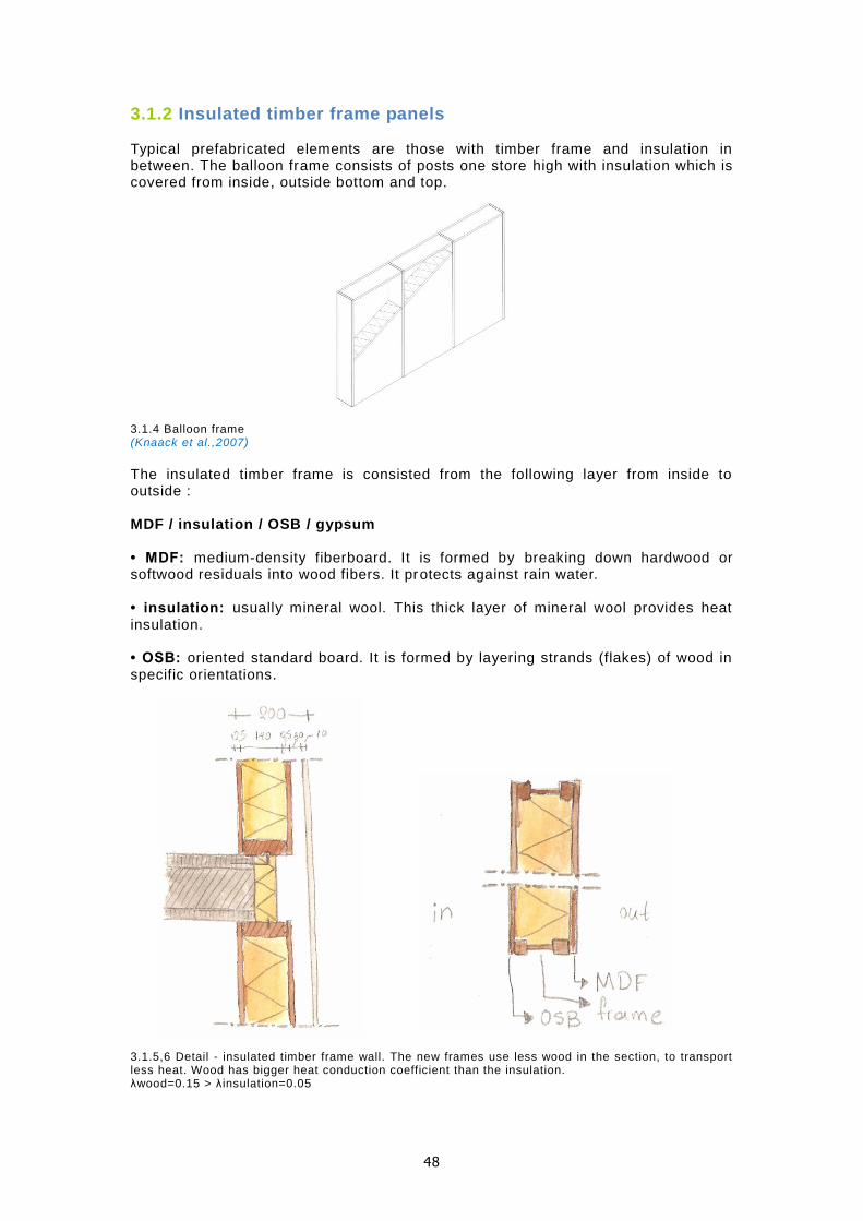
3.1.2 Insulated timber frame panels Typical prefabricated elements are those with timber frame and insulation in between. The balloon frame consists of posts one store high with insulation which is covered from inside, outside bottom and top. 3.1.4 Balloon frame (Knaack et al.,2007)
The insulated timber frame is consisted from the following layer from inside to outside : MDF / insulation / OSB / gypsum • MDF: medium-density fiberboard. It is formed by breaking down hardwood or softwood residuals into wood fibers. It protects against rain water. • insulation: usually mineral wool. This thick layer of mineral wool provides heat insulation. • OSB: oriented standard board. It is formed by layering strands (flakes) of wood in specific orientations. 3.1.5,6 Detail - insulated timber frame wall. The new frames use less wood in the section, to transport less heat. Wood has bigger heat conduction coefficient than the insulation. λwood=0.15 > λ insulation=0.05

49
3.1.7 Timber frame wall is also used in combination with cladding (Knaack et al.,2007)
Advantages
1. high insulation against cold 2. use wooden frames for load bearing structure 3. prefabricated
Disadvantages
1. low thermal mass 2. sounds hollow – not good feeling 3. making holes can break the vapor barrier – cause draft of rainwater to
the inside
3.1.3 Evaluation – Targets for new system The advantages and disadvantages from the lists above can be merged on one list that would present all the features that the object of this research should have. In the list some extra function that were not mentioned in the standard systems are presented in order to improve the energy consumption and the indoor climate.
1. collect heat 2. store heat / thermal mass 3. regulate humidity 4. high insulation 5. use wood as load bearing structure 6. do not have a hollow sound 7. safe from braking the vapor barrier 8. prefabricated
The study of two standard systems of the insulated cavity wall and insula ted timber, have possibilities for improvement and combination of elements for the proposal of a new system. Focus on:
1. transition from traditional to frame panels 2. integrate layers in one (big) element 3. fully finished panels 4. smart fixing systems
3.1.8 From traditional to prefabricated frames and integration of ceramics in the prefabricated elements

50
3.2 The model The model of the new system concerns the close part of the façade. It is an improvement of the standard prefabricated timber frame façade panel, taking some elements from the insulated wall and integrated some extra functions than those that are embedded in the two standard systems that improve its performance. The model is presented in two parts: as a façade system and as part of a case study for the Concept House. The first part introduces the façade system with all the elements and functions and the second part the design and integration (see 4) of the system into the timber frame panels for the Concept House.
3.2.1 Functions and Components Functions are efficient when placed in the appropriate layer in the façade system. The following table summarizes the extra functions that are added to the timber frame panel at the new system. The layer of the components and sub-components that perform the required function is the first step to the design of the model. 3.2.1 Table with the required functions, layers and components. Loam and ceramics are highlighted with red as the materials which are studied more extensively
Layers of the facade
The layers and the main functions of the proposed façade system are illustrated in the design of the schematic section. The structure of the façade is timber frame. The layers and their functions from inside to outside:
1. Loam: loam balances the indoor climate by regulating the levels of relative humidity and storing heat into its mass from the inside heating loads and the water circulation.
2. Water circulation: water circulation in pipes is used during winter for heating and during summer for cooling the interior.
3. Wood panel (OSB): the first layer of wood panel composite protects the insulation from humidity coming from the interior.
4. Insulation: a thick layer of insulation increases the heat resistance of the total construction.
5. Wood panel (MDF): the second layer of wood panel composite protects the insulation from external humidity and water.
6. Cavity: a ventilated cavity drains the rain water out of the construction and functions as a thermal break between the two skins
7. Ceramic cladding: ceramics with their corrosive resistant properties can endure in solar radiation and rainwater. Heat collection is achieved though this layer by integration of water tubes into the ceramic tiles. Porosity and capillarity allow cooling by evaporation with the use of water sprinkles.
FUNCTION LAYER COMPONENTS SUB - COMPONENTS
collect solar heat outside water circulation copper pipes
store heat inside mass loam
cool / heat by radiation
inside water circulation rubber pipes
regulate relative humidity
inside mass loam
protect from solar radiation
outside cladding / shading ceramics

51
8.
3.2.2 Schematic section sowing the layers of the façade and their main functions. Loam at the inside layer and ceramics as cladding to the outside are highlighted since they consist the main components of the façade system
Façade system and components The outer layer of the façade is used as an energy source which is used for the heating of the interior though water circulation to the inner layer. The system of the façade consists of:
the energy collection (energy outer layer of façade) the energy transmission (heat pump) the energy storage (aquifers) the energy radiation (water circulation inner layer)
3.2.3 diagram sketch of how the system works Summer: collection of heat, storage in the ground and use of energy for transmission of cold water to cool the interior (left). Winter without sun: no water circulation to the outer layer to avoid frost, energy use for transmission of warm water f rom the ground to heat the interior (middle). Winter with sun: water circulation to the outer layer to collect warm water and storage to the ground. Energy use to transmit warm water to heat the interior (right).

52
3.2.2 Inner layer: water circulation for heating and cooling The properties of loam have already been studied extensively. The function, the prefabrication and installation depends in a grate extend on the choice of the water pipe system that is chosen. The choices of the water system that were studied, the description of their performance and a comparison between the two is described. The water system as part of the thermo active system has already been introduced in the literature study. The water pipe system and the capillary mat are tw o systems that have found to be used for internal heating and cooling. 3.2.4,5 pipes and capillary mats used for heating and cooling in thermo-active building systems (wall-heating.com) (tootoo.com) Indoor climate and performance A big advantage of those systems in the indoor environment is that the embedded heating system creates an even heat distribution which is perceived as a pleasant radiation like the one from the sun. 3.2.6,7 The radiation of heat or cold from the thermo active building systems from the wall or floor is even and pleasant to the human body. The heating of space with a radiator on the other hand creates temperature differences in the room (wall-heating.com) (bioclina.de) (wall -heating.com)
The capillary mat optimizes the heat distribution more even than the water pipe system because the capillary tubes are located in a distance of 30mm, but the pipes at a distance of 100mm – 150mm. This practically means that the response in temperature is faster. 3.2.8,9 the heat distribution of the pipes and capillary mat. The Tmin (minimum temperature) is about the same as the Tm (mean temperature of the surface) at the capillary mat, although in the pipe system the difference in temperature is different. (bioclina.de) (radiantcoo ling.org)

53
3.2.10,11 the response of the of capillary mat in temperature change in heating (left) and cooling (right) (bioclina.de) (radiantcooling.org) Pumps and water distribution The efficiency of the system depends also on the energy that is demanded for the water distribution into the loops. The pump energy is related to the velocity of the water. In order to reduce the pump energy the velocity should remain bel ow 1m/s. For example the velocity of u=1m/s will result in a pressure difference of 250Pa/m. P = 0.5*ρ*u² P: pressure [Pa] ρ: volumetric mass of water [kg/m³] u: water velocity [m/s] However the resistance of a pipe is a very important factor. 1 m/s in a pipe of internal diameter 16mm will result in total resistance 900Pa/m 0.5m/s in a pipe of internal diameter 16mm will result in total resistance 290Pa/m 0.5m/s in a pipe of internal diameter 6.4mm will result in total resistance 600Pa/m Those examples show that lower velocities are required in smaller tubes in order to prevent high pressure differences (Bokel et al., 2009). The examples above show that there is a relation between the diameter of the tube, the velocity of the water and the pressure. All those aspects affect the pump energy. The water in a Capillary mat system runs through many parallel capillary tubes, rather than running through just one tube, as in a system with thicker tubes. The typical velocity of flow with the Capillary tubes averages only 10 to 20 cm/second or (0.1 to 0.2 m/s) (radiantcooling.org). 3.2.12 at the capillary mat the pressure is distributed to many little tubes (left) 3.2.13split of the total mass flow into parallel fluid channels in both cases of the human body circulation and the capillary tube mat (right) (radiantcooling.org) (clina.co.uk)

54
Control Regulation of the system can be made by means of heating circuit manifolds, actuators and room thermostats. On each floor a heating circuit manifold is installed which supplies the different rooms with warm water. Room thermostats allow the adjustment of individual rooms. These are connected to the actuators which control the opening or closing of the heating circuits (wall-heating.com). To prevent condensation during cooling a dew point sensor is used. 3.2.14 control system with room thermostat and actuator (left) 3.2.15 each loop can be controlled separately (right) (wall-heating.com) ( roth-canada.com)
Materials The materials for the water pipes and capillary tubes are thermoplastics. For the capillary tubes polypropylene (PP) and for the water pipes polyethylene (PE) is used. The advantage of the pipes over the capillary mat is that within the bigger diameter of the tube (100 – 160mm over 3,5mm) a protective aluminum layer can be added to make the pipe maintenance-free, resist a maximum temperature of 95°C and resistant air penetration that can cause obstruction in performance. 3.2.16 oxygen proof pipes 3.2.17at the capillary mat (wall-heating.com) (beka-klima.de) Drilling The drilling at walls with water pipes is possible as long as the pipes are avoided. This can be done using a temperature foil. At the capillary mat system drilli ng is not possible because it is very dense, but a solution can be the hanging of objects from the roof with rails like at the exhibition halls. 3.2.18 temperature foil for drilling 3.2.19 rail system for hanging elements from the top (wall-heating.com) ( ashanging.com)

55
Choice The results from the comparison between water pipes from and capillary tube mats are presented in the table. The water pipes system found to have more advantages than the capillary tube mat and was selected for the system.
3.2.20 comparison between water pipes and capillary tubes mat 3.2.3 Integration of water pipes into loam The layer of loam includes embedded into its mass the water pipes for heating and cooling. The integration of pipes into the loam affects the production of the loam components and their prefabrication. The support of the final components on the timber frame panel affects also the process of prefabrication. The first approach was a modular design with different interfaces and components for the assemblage and fixation to the timber frame panel. As a result of a further research and visit to building sites and contact with companies an integral product that contains all components (loam, water pipes and fixing interfaces to the panel) was found. The product is a prefabricated panel with embedded water pipes and interfaces for fixation on the panel, designed and produced by the company WEM Wandheizung GmbH. Modular approach The first modular approach suggested the production of loam in compressed earth blocks, (CEBs). The CEBs are designed with a reception of their surface in one side so as to provide space for the integration of water pipes and with perforations in their mass at the same direction to provide space for the placement of horizontal rails for support to the timber frame. The idea was to divide the surface that needs to be filled in with loam i n blocks taking the standard dimensions as a starting point (29.5x14x9cm) and having different blocks produced in response to the needs of the integration of the water pipes. 3.2.21 problems in the integration of water pipes into a wall of CEBs (left) 3.2.22 division of the wall surface into CEBs (right)
water pipe system capillary tube mat system
heat distribution ( + + + ) ( + + + + )
system response ( + + + ) ( + + + + )
energy demands ( + + + + ) ( + + + )
control ( + + + ) ( + + + )
materials ( + + + + ) ( + + + )
maintenance ( + + + + ) ( + + + )
drilling ( + + + + ) ( + + + )
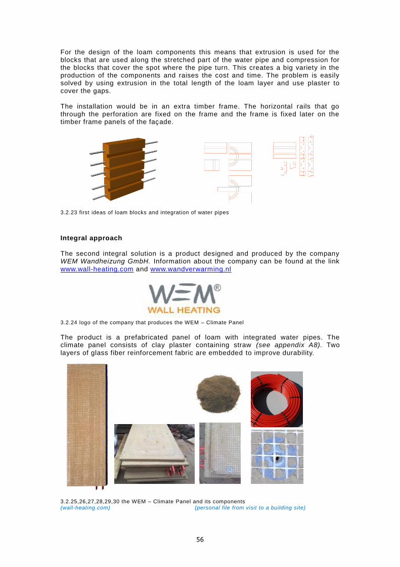
56
For the design of the loam components this means that extrusion is used for the blocks that are used along the stretched part of the water pipe and compression for the blocks that cover the spot where the pipe turn. This creates a big variety in the production of the components and raises the cost and time. The problem is easily solved by using extrusion in the total length of the loam layer and use plaster to cover the gaps. The installation would be in an extra timber frame. The horizontal rails that go through the perforation are fixed on the frame and the frame is fixed later on the timber frame panels of the façade. 3.2.23 first ideas of loam blocks and integration of water pipes Integral approach The second integral solution is a product designed and produced by the company WEM Wandheizung GmbH. Information about the company can be found at the link www.wall-heating.com and www.wandverwarming.nl 3.2.24 logo of the company that produces the WEM – Climate Panel The product is a prefabricated panel of loam with integrated water pipes. The climate panel consists of clay plaster containing straw (see appendix A8). Two layers of glass fiber reinforcement fabric are embedded to improve durability.
3.2.25,26,27,28,29,30 the WEM – Climate Panel and its components (wall-heating.com) (personal file from visit to a building site)

57
The installation in five steps is complete. The steps are:
1. placement on the wall and screw to stabilize 2. join and connect to the heating manifold using composite metal plastic pipes 3. reinforcement of joints 4. finishing of the surface 5. painting
3.2.31,32,33,34,35,36 steps of installation and finishing surface (wall-heating.com) (personal file from visit to a building site) Composition of loam The properties of loam change with the use of additives and with the change in the proportion of the particles, which is consisted by (gravel, sand, silt and clay). The use of additives has some disadvantages (see appendix A2). From the research on examples of products that are already on the market the use of straw as an additive is quite common. There is not one fixed value that describes the mix of loam with straw. The quantity of straw and the way of production (compressed or rammed) affect the properties (density, weight, vapor absorption etch) of the earth component. Straw is considered as a possibility for the type of loam that is proposed for the system. The properties of loam that are of importance are: the thermal mass, the regulation of relative humidity and the reaction in case of condensation. The use of straw in the loam reduces all of those three desired properties (see appendix A7). It should be mentioned that the quantity of straw can vary. So straw can be used in the optimum proportion that does not affect much the properties that were mentioned or does not create problems of internal condensation (especially in more than 25cm thick layers). Some of the advantages of using straw are the reduction of shrinkage and the binding force, but those can also be improved by special treatments . Another advantage is the reduction in weight that is desirable for the installation of the prefabricated element façade. Density of loam: The increase of density increases the heat storage capacity of loam and its vapor absorption. On the other hand the higher the density the higher the weight of the component.

58
Thickness of loam: The thickness of loam should not be more than 12.7 cm in order to allow the release of heat into the interior. Increase in width might also cause condensation problems (see 2.6.2). The bigger is the thickness, the heavier the panel and the more difficult its installation in terms of transportation, manipulation on site and support on the construction. For the vapor absorption the first 1.5cm absorbs the most water vapor and thicknesses more than 4cm do not make much difference. Evaluation: A good performance of a system can save a lot of energy and money in long-terms. A difficulty in installation might be evaluated as worth making if the performance shows impressive improvement. For this reason the aspects of “density and thickness” of the loam are tested into CAPSOL. The results contribute to the final decision. From the literature study the estimation for the better performance of the inner layer of loam is a thickness of 0.12m and a density of 1600kg/m³. The reduction of weight is an aspect also desired. A slimmer solution would be with an inner layer of 0.035m thickness. In order to start the calculations in CAPSOL the combination of 0.035m thickness and 1600kg/m³ density is chosen. The model is tested in more combinations (0.12m and 1600kg/m³ / 0.035m and 700kg/m³ / 0.12m and 700kg/ m³) to test its optimum performance and understand more about the effect of those two properties in the performance of the system. With the change of the density the λ – value (heat conduction coefficient also changes from 0.65W/mK to 0.20W/mK for the “heavy” and lightweight straw loam respectively). Proposal For Concept House the WEM – Climate Panel can be a good solution for the inner layer since it combines the basic prerequisites for the proposal of the new system. Those are:
1. the integration of loam and pipes in a prefabricated component 2. the ease in installation 3. the “slim solution”
For the final decision some aspects for the design of the panels (thickness) and composition of loam (additives, density) which affect its thermal properties and regulation of relative humidity and condensation as mentioned are evaluated (see appendix A2 and A7) and tested in CAPSOL. Apart from the performance of the material itself which is going to be tested by dynamic computational tools more aspects that concern the overall durability of the component, the interior finishing’s which is important for the ease in use are proposed here. Durability: The replacement of the fiber glass reinforcement: The mesh provides more stability to the panel and improves its “edge impact strength”, but the use of 100% natural fibers is preferable.
3.2.37, 38 jute fiber with mesh density 20x17mm (groenebouwmaterialen.nl) (thermo-hanf.de)

59
Interior finishing’s:
After the loam surfaces have been placed on the timber frame panel the edges are covered and reinforced with a 1 – 1.5cm layer of loam which is reinforced with pieces of mesh. The result is a smooth surface of loam which can be painted with a variety of 100% natural mud paints. The main ingredient clay powder, gives a soft -grain structure. No chemical solvents are used for the dilute of the paint, just water. The paint is moisture regulating and vapor permeable. It can be easily applied by the users with a roller or brush.
3.2.39 natural mud paint at the natural color ( left) 3.2.40 variety of colors to cover clay plaster (middle, right) (tierrafino.com) (claytech.de)
In the Netherlands is quite common the use of wallpaper for the cover of the interior walls. The wall paper consist a vapor barrier but this depends on its materials. Plastic and synthetic textile wallpapers block the absorption of water vapors, thus the use of loam as a moisture buffering material (see appendix A7). Paper or textile wallpapers could be considered as a possibility since they can also offer a substantial contribution to the buffering of moisture to the indoor climate (Berge, 2009). The glue though, which is necessary for the cohesion to the under layer and the paints that are used for the pattern of the wall paper (alkyd paints, animal glue paint) block the regulation of relative humidity of loam.

60
3.2.4 Outer layer: water circulation for water collection and cool Ceramic tiles are used for the cladding of the facade. The function of the outer layer of the façade contributes to the energy saving of the performance of the façade system. The cladding is installed with a distance of a ventilated cavity from the construction and functions as a buffer between the outer environment and the external panel of the timber frame panels. Water circulation embedded in the perforations of the ceramic tiles function as heat collectors from sun radiation. At extreme hot, sprinkles of water cool the circulating water in the pipes by evaporation. 3.2.41 Conceptual sketch of the function and components of the façade cladding
The water that circulates on the façade is heated or cooled according to the season and the time of the day. The heated or cooled water is used directly for the improvement of the indoor climate or is stored on the ground for future use. Reference model A reference model, “solar energy plant” imagined by Marcel Billow (2006) is similar to the concept for the outer layer and storage space. The idea is to create collectors in walls or roofs as solar energy plants with inserted capillary tube system.
3.2.42 Conceptual (Knaack, Klein, Bilow, 2008)
Ideas…
Within the design process other concepts came into discussion. One, using ceramic cylinder and half cylinder could work with the dark surface exposed during winter and the white and glazed during summer. Since the Dutch climate does not change so dramatically during the year and the case study examines a ventilated cavity, this solution would not work efficiently. 3.2.43 Concept developed during the design phase but rejected for the current study

61
Solar collection Solar collectors are usually used at the roof of buildings. The advantage of using those systems on the roof instead of the façade is that the app earance is not important, which makes the choice of materials and design easier, the exposure to the sun is more, the components do not have many restrictions in dimensions and the adjustment of the inclination is easier. Since the maximum of performance i s important the function during the whole year (winter and summer) can be ensured by the insulation of the collectors (like the evacuated solar tube ). All those advantages are limited for the use of solar collectors on the façade because of the building su n obstacles (trees, other buildings), the orientation that might be not favorable, the increase of weight, the limited space and the difficulties in maintenance. Despite all the difficulties, a system of solar collection on the façade could have many possibilities and those are explored here. The façade of a building covers a big area on which a big amount of incident solar radiation heats up is surface. This energy can be used as a source. An introduction of the choices that led to the design of the system and the possibilities are elaborated. The orientation is one of the most important factors that determine the function of the façade as a solar collector. The most favorable orientation is the south. The south façade receives the most of the solar radiation in amount and intensity. 3.2.44 Irradiance in W/m² on vertical surfaces oriented north, east, south and west. Horizontal axis: local solar time in hours. Graphs computed for 50° latitude north, using the ASHRAE clear sk y model and a ground reflectivity of 0.2. (ASHRAE, Sun Shading)
The components of the façade with the solar collectors can be inclined only by a few degrees; the rotation of components is also possible but is more complicated and expensive. The ceramic t iles are inclined to receive more direct the sun rays but stay fixed to avoid big complexity on the façade system and cost. The materials that are used at solar collectors need to absorb heat. The texture should be dull, the color dark, the material should not insulate the water surface that collects heat. Materials with high conductivity and high density are used. Glass is also used at solar collectors because it lets the sun radiation to penetrate its surface

62
and traps the heat inside to heat up the water. The dark background helps in absorbing more solar radiation. The choice of ceramic tiles for cladding was made for architectural reasons. It is a material that does not overheat and feels comfortable to touch, which makes it suitable for a dwelling. In addition go that many of the properties of the ceramics can be used so as the cladding of façade can function as an energy surface. Ceramics tiles painted with dark color and dull texture reflect less light and collect more heat in the embedded water pipes. The thermal mass of the ceramics (volumetric heat capacity KJ/m³k) is 1360 which is among the materials with relatively high thermal mass (water: 4186, concrete: 2060, earth, adobe: 1300). The density depends on the porosity, although for structural reasons the ceramic tiles are dense in order to avoid cracks at the connections for the attachment to the support grid. Its conductivity (brick: 1.3, concrete 0.3, insulation 0.05) allows the radiation of the sun to penetrate in its mass and its thermal mass sustain it. Thus heat can be collected though water circulation. The tiles designed with perforations, provide space for the water circulation in copper tubes that are used to collect heat during summer and during the sunny days of winter. 3.2.45 basic features for the choices about solar collection 3.2.46 basic features for the choices about (sunstatesolar.com.au) Cool One method of passive cooling is the use of air and water to cool by evaporation. During the hot days water can be sprinkled from the top of the façade on the ceramic tiles. The porosity of the ceramics allows the water t o penetrate with capillary action onto the surface of the copper tubes. The outside air that blows on the façade penetrates through the capillarity the structure of the ceramic tiles and reaches the water circulation that is cooled. 3.2.47 air cools the water inside the ceramic bottle by capillary action (left) 3.2.48 combination of water and air to cool by evaporation (right) (shop.royalvkb.com) (wikipedia)
ceramic tiles collect heat
shape / inclination flat tiles inclined to receive more direct the solar
radiation
color / texture dark color and dull texture to avoid reflectance
thickness small thickness to prevent insulation of water
copper tubes collect heat
shape cylinder: receives radiation in the biggest amount
of its surface
thickness small thickness to prevent insulation of water
material high heat conductivity / high density

63
Summer situation
The collection of heat is more successful during summer. The sun is closer to the surface of the earth and the duration of sun light is longer.
3.2.49 horizontal diffuse solar radiation (top) 3.2.50 direct solar radiation (bottom) (CAPSOL software)
During summer the water that runs through the ceramic tiles can be warmed up during the day and stored in the ground for use during winter. This is efficient in the sense that the façade works as a heat source. A second alternative of the warm water on the outer layer is to circulate it at the inner layer during some chilly nights for heating the interior. As seen on the graph the temperature between June and August can drop during the night down to 6°C. Although with some extra clothing and by taking into account the stored heat in the house during the day, this would not be necessary taking into account that the circulation of water would demand some energy. 3.2.51 outside temperatures for July in the Netherlands (left) 3.2.52outside temperatures at the day with the highest temperature (right) (CAPSOL software)

64
Winter situation During the winter the water circulation is turned off during cloudy days with the temperature below zero to avoid frost. The façade systems benefits from the heat collection during summer. The hot water that was stored on the ground is used to heat the interior of the houses. 3.2.53 outside temperatures for December in the Netherlands (left) 3.2.54 outside temperatures at the day with the lowest temperature (right) (CAPSOL software)

65
3.3 Hand Calculations and Computational Tools Building physics calculations gave a clear view of the efficiency of the new system. Hand calculations and the software CAPSOL as a computational tool were used. The results of the performance of the façade were compared with the two standard systems that are used extensively in the Netherlands: the insulated cavity wall and the timber frame panels. The hand calculations test the heat loss and demands in heating and cooling at the worst situations. In CAPSOL the energy use in relation to the thermal dynamical behavior in the examined space and the ventilation folds are calculated. The model is tested in summer and winter in order to calculate the total energy consumption for the whole year. The design parameters and function references of the model give all the necessary information for the input for the calculations.
3.3.1 Design parameters The procedure of the input of the design parameters that is presented here concerns the new façade design. The same procedure with different input of the façade elements is repeated for the other two standard systems, (insulated cavity wall and timber frame panels), At the end the results of all three systems are compared. All of the three models are tested under the same conditions. The input of the information about the examined space is the same. The area, volume, orientation, area of openings, adjacent spaces, ceiling floor and interior walls are the same. The only input that changes is the close part of the façade and the glass properties of the windows.
Dimensions – shading elements
3.3.1 plan and front view of the examined space – orientation: south
3.3.2 the geometry is calculated from the inside view eg. the height is calculated from ceiling to floor
GEOMETRY & ORIENTATION OF THE ROOM
volume: 137.7m³ Façade/
close part - south:
16.7 m²
area: 51.19 m² Façade/
close part - east:
6.07 m²
height: 2.69 m Façade/
openings south:
10.7m²

66
3.3.3 External rotated and movable louvers to adjust to the needs of any season and time of the day. The louvers cover all the openings of the south façade (door and windows)
Function References The function references define the boundary conditions that need to be met for the functional requirements of a space. Those requirements vary acco rding to the use of the space and the user ’s needs and concern levels of comfort. The most essential criteria are thermal, visual, hygiene and acoustic comfort. The design of the façade needs to meet the demands of those necessary values to the inside. In this chapter the targets of the interior levels of temperature and the boundary conditions are defined. The thermal comfort is examined here since it is related to the energy consumption for heating and cooling. The thermal comfort is directly linked to the hygiene comfort since the ventilation of a room affects the temperature levels and the activity levels, which create the internal heat production. Each user defines comfort in a different way, thus it is difficult to specify comfort -related factors. For that, recommendations are provided based on guideline values. (Knaack et al.,2007). For the specific case study of the Concept House, the space that is examined is a living room and kitchen (area: 51.19m² and volume: 137.7m³). The house is considered to be occupied by a four member family, two adults and two young children.
Room Temperatures An average whole-house temperature of 19°C has been assumed as a typical acceptable value for winter conditions (with average indoor clothing levels), based on recommendations by BRE and the results of field studies (bre.co.uk). Typical values of living rooms are in the 18-22°C range and for bedrooms 17-20°C. Special provisions are recommended for the elderly and disabled to ensure a stable 21°C for day and night. For summer conditions and lighter clothing acceptable average indoor temperatures are in the 23-26°C (Yannas, 1994). Temperatures of more than 26 °C should be avoided. The Target Temperatures for the Concept House are, 19°C for winter and 26°C for summer. 3.3.4 levels of temperature comfort at the inside picture made from (Yannas, 1994)

67
3.3.5 function reference during winter. Target temperature: 19°C 3.3.6 function reference during summer. Target temperature: 26°C Internal Heat Load Internal heat load is the amount of heat that is produced by the occupants, electrical devises, like lights, computers and kitchen devices. 3.3.7 data for internal heat production (carbonfootprint.com/energyconsumption.html) (absak.com/pdf/docs/loadeval.pdf) (energysavers.gov/your_home/appliances/index.cfm/mytopic=10040 )
The data from the table were used to create a graph that was used in CAPSOL for the internal heat load according to the function reference graph. The pick value of the graph (internal heat production: 800W) was used as an input for the hand calculations for summer.
INTERNAL HEAT LOAD
people / equipment hours use
per day days use per year
watts [W] killowatts per year
[kWh]
people 6.5 360 80 187.2
oven 1 135 950 128.25
microwave oven 0.3 96 750 21.6
dishwasher 1 120 1200 144
refrigerator 24 /3 = 8 360 750 210
coffe maker 0.16 360 1000 57.6
television 6.5 360 120 280.8
light bulp 4 360 25 36

68
Ventilation Fold The ventilation of space is necessary for the removal of dust, moisture, odour, CO 2
and other contaminations of the internal air. There are two different methods of ventilating a room: natural and mechanical ventilation. A minimum fresh air-supply of 20-35m³ per hour per person is recommended. Translated to an average whole-house value of air changes per hour, this may range between 0.5-1.0 ac/h. In winter the design objective is to ensure adequate air quality with no unnecessary increase in heat loss. The CO2 should be kept at a maximum of 1.0 – 0.15ppm. In the Concept House natural ventilation is used. Constant ventilation is provided by trickle ventilators which are integrated into the window timber frame. The ventilation rate is 0.625 dm³/s/m² (= 0.83 air changes / hour) and the air tightness is 0.15 air changes / hour (=0.11 dm³/s/m²).
3.3.2 Hand Calculations The hand calculations gave the first tangible sense of the situation which was evaluated with the conclusions of the testing from the computational tool CAPSOL. The hand calculations are static without taking into account the parameter of ti me. The first important information about a façade is the U-value which determines the resistance of the heat transfer through the façade. A passive system like the one of Concept House targets a low U-value. The heating and cooling loads are calcula ted at the worst situations which are: For winter: the lowest outdoor temperature, with no internal heat production and no sun. For summer: the highest outdoor temperature, with sun load and internal heat production.
3.3.8 the three façade systems that are tested

69
Heat resistance and U -values The amount of heat loss by a construction is essential information for its performance and contribution into a passive system. The values that were calculated at this stage are the heat resistance of air on air [R l] and the heat flow density U-value. To simplify the hand calculations the water circulation in the inner and outer layer of the new facade system was not taken into account. The heat resistance of a construction is calculated of ai r on air. Formulas used for the calculations:
Results and values input:
Heating and Cooling loads
3.3.9 formulas and data for calculations
STANDARD SYSTEM - INSULATED CAVITY WALL
material width [m] heat conduction
coefficient [W/mK] R - value [m²K/W]
facing brick 0.1 0.83 0.13
cavity 0.04 ( - ) 0.15
insulation (mineral wool)
0.1 0.05 2
concrete 0.1 2 0.05
total 0.34 2.5*
UTOT = 0.4 [W/m²K]
STANDARD SYSTEM - TIMBER FRAME PANELS
material width [m] heat conduction
coefficient [W/mK] R - value [m²K/W]
ceramic tile 0.01 0.83 0.012
cavity 0.03 ( - ) 0.15
MDF 0.012 0.13 0.09
insulation (mineral wool) 0.14 0.05 2.8
OSB 0.012 0.13 0.09
total 0.204 3.312*
UTOT = 0.30 [W/m²K]
R = d/λ [m²K/W]
R : heat resistance of a layer of a material [m²K/W]
d: thickness of a layer [m]
λ : heat conduction coefficient of the material [W/mK]
*Rl = re + Rc + ri [m²K/W]
Rl : heat resistance of the construction of air on air [m²K/W] re : heat transfer resistance outside [m²K/W] ri : heat transfer resistance inside [m²K/W]
Rc = R1 + R2 + R3 + … + Rn [m²K/W]
Rc: heat resistance of the construction [m²K/W]
Utot = 1/ Rl [W/m²K]
Utot : overal heat transfer coefficient [W/m²K]
NEW SYSTEM
materials width [m] heat conduction
coefficient [W/mK] R - value [m²K/W]
ceramic tile 0.01 0.83 0.012
cavity 0.03 ( - ) 0.15
MDF 0.018 0.13 0.13
insulation (cellulose) 0.2 0.04 5
OSB 0.018 0.13 0.13
loam 0.035 0.65 0.04
total 0.321 5.63*
UTOT = 0.17 [W/m²K]

70
Winter Situation - heating The total heating load is: Qheating = Qventilation + Qtransmission. The Q internal heat production of people and equipment is neglected, so as to calculate the demands in the worse situation. 3.3.10heat loads at a worse heating situation
Qtransmission = Qwall + Qglass = (Aw*Uw*ΓΤ) + (Ag*Ug*ΓΤ) = (22.77*0.17*29) +(10.7*0.9*29) = (112.25) +(279.27) = 391.52 W Qventilation = (ΓΤ)*(ventilation rate + air tightness)*A*ρc = (29)*(0.737)*(51.2)*(1200) / 1000 = 1313.15 W Qheating = Qventilation + Qtransmission = 1313.15 + 391.52 = 1704.67 W
Summer Situation - cooling At summer, the Qventilation and Qtransmission bring heat into the inside, so the cooling load is equal to the sum of the loads of ventilation and transmission. Qcooling = Qventilation + Qtransmission + Qsun + Qinternal heat . 3.3.11heat loads at a worse cooling situation
Qtransmission = Α*U*ΔΤ [W]
A : area of wall or window [m²] U : overall heat transfer coefficient [W/m²K] ΔΤ : temperature difference between inside and outside [K]
Qventilation = ΔΤ*(ventilation rate + air tightness)*A*ρc [W]
ΔΤ: temperature difference between inside and outside [K]
ventilation rate & air tightness [dm³/s/m²]
ρ : density [Kg/m³]
c : specific heat capacity [J/kgK]
* the overall result for Qventilation is divided by 1000 to convert dm³ to m³

71
Qtransmission = Qwall + Qglass = (Aw*Uw*ΓΤ) + (Ag*Ug*ΓΤ) = (22.77*0.17*4) +(10.7*0.9*4) = (15.48) +(38.52) = 54 W Qventilation = (ΓΤ)*(ventilation rate + air tightness)*A*ρc = (4)*(0.737)*(51.2)*(1200) / 1000 = 181.12 W Qinternal heat = 800 W (see 3.4.3 CAPSOL –input) Qsun = (10.7)*(600)* 0.6 = 3852 W Qcooling = Qventilation + Qtransmission + Qsun + Qinternal heat = 181.12+ 54 + 800 + 3852 = 4887.72 W 3.3.12 calculation for sun load Pump energy The pump energy as mentioned before has an important role in the efficiency of the system. The calculation of the pump energy is not part of the calculat ions that concern the indoor climate, but its performance contributes to the sustainability of the system. Since the heating period is longer than the cooling period a calculation
of the energy of the pump was made considering the heating load Qheating =
1704.67W as the main load. A warm supply of 77.43 W/m² for a wall area of 22.77m² (Φc = 1704.67 W) and a temperature difference of 5 K between supply and runoff water will lead to this water volume flow: qv = Φc / ρcΓΤ = 1704.67 / (1000)*(4200)*5 = 0.000081 m³/s = 0.081 l/s = 291.6 l/h. For an area of 22.77m² this is 12.8l/hm². In a wall with pipes that have an internal diameter of 12mm the velocity will be: u = qv / A (m/s). A is the surface of the pipe = πr² =3.14*0.006² = 0.00011304m² and u = 0.000081/0.00011304 = 0.716 m/s. The pump energy, P=0.5ρu² = 256.32 Pa. The velocity affects the energy of the heat pump and it should not be more than 1m/s. The result of 0.716m/s is acceptable for the efficient performance of the heat pump (Bokel et al., 2009).
Qsun = Αwindow*Solar load*g [W]
A : area of window [m²]
Solar load : how much heat load prospects on the façade [W/m²] g : how much sun light goes through the glass

72
3.3.3 CAPSOL - Input In CAPSOL the calculations are dynamic and are based on the changes of temperature and the energy demand according to the time passing. At different seasons and times during one day the requirements for cooling, heating and sun shading vary. The results show how much energy is needed for the room annuall y. Several inputs were made for design parameters like the materials of the construction, orientation, heat sources and use through time. Two studies were accomplished: one for summer situation - a cooling load calculation and one for winter situation – a heating load calculation. Taking into account the climatic conditions in the Netherlands, the year was divided in two seasons, summer and winter. The winter period is November -March where heating is demanded and the summer period is from end of May-August where cooling is demanded. April, May, September and October are considered to be neutral where no heating or cooling is needed.
Input – winter model Starting the model in CAPSOL the first input is about the season, the basic zones, the solar load and the ventilation zone. The basic zones are inside and outside the room. The ES (with sun) type is more realistic, thus it is used for the calculations. The IV type for the inside zone is also more realistic because it calculates the temperature of the radiate walls and the temperature of the air.
3.3.13 basic zones of the model, ES (with sun load) is the external solar zone and IV is the indoor comfort zone
The second input <Function Reference> considers the outside temperature, the energy, the solar load, the ventilation fold. All values are time dependent. 3.3.14 function references of the model for the winter situation. T02 is the target temperature for the inside. 19ºC is the minimum acceptable value of temperature to have indoor comfort. The graph shows that the temperature can drop to 16 ºC when the space is not used. P02: internal heat load, T01: outside temperature, T02: inside target temperature, V01: ventilation fold, B01: direct beam solar radiation, D01: diffuse horizontal solar radiation

73
T02 is tested in two cases. The first case targets to achieve a constant value of 19°C indoors. The second case allows the temperature to drop down to 16°C when the space is not occupied. The model is tested in both cases.
T02 needs to be at least one degree higher at the input in order to avoid that the temperature drops below the accepted minimum temperature. The input for constant temperature is T02=20°C and for the reference graph 17°C <T02<20°C.
3.3.15 Target temperatures for winter. Constant at 19°C (left) and between 16 and 19ºC (right)
The estimated internal load, the amount of heat that is produced from the occupants and the electrical devices in the room is presented on a graph on a period of 24hours.
3.3.16 Dynamic internal heat load production in 24 hours. The same applies to winter and summer
The next input <Walls> includes all the information about the construction, the materials, the thermal properties of the materials and the adjacent spaces. Some of the materials do not match with the materials found in the CAPSOL database. Because of that the collection of all the values that affect the thermal resistance of the building and the thermal mass were necessary. Those values are: the density (ρ), the heat conduction coefficient (λ) and the specific heat capacity (C) (see appendix A8). In the façade there is water circulation in pipes in the outer and inner layer. The water circulation at the outer layer which is used for heat col lection is not taken into consideration since it does not affect the indoor climate. The water circulation of the inner layer is important since it is used for heating and cooling by radiation. For the input of the layer of water pipes into the loam the to tal volume of the water was divided by the area of the close part of the façade on which it is installed. In CAPSOL two walls were created for the two different orientations (newwater_s and newwater_e), so as the layer of the water.

74
3.3.17 input of all the construction elements that surround the room new_s: the façade facing south, new_e: the façade facing east, glass: the triple glass, Bwalls: the thick interior walls that separate the apartments, Swall: the interior walls, ceiling and fl oor.
3.3.18 input information for the close part of the south façade
3.3.19 input information for the triple glass
The input of the glass properties is important because it affects the indoor climate and the power supply. The U value of the glass shows how much heat is transmitted from outside to inside and the g value shows how much sun radiation goes through the glass. 3.3.20 the properties of the triple glazing that are used for the Concept House

75
At the <Zone Ventilation> the way of ventilation is described and is linked to the function reference input. The <Points> are linked with the results and show where the nodes are calculated. Here the points show the outside and inside zones and the layer of water pipes that provide the heating and cooling loads. 3.3.21,22 zone ventilation and points
The <Controls> are linked to the function references and to the points and determine what is calculated. This table changes from winter to summer since t he demands are different. 3.3.23 controls for winter situation. The sensor point shows indoor temperature which is the target temperature, the purpose is heating for winter, the power is provided by the south and east façade were water pipes are integrated and the maximum power is 1709W as was found at the hand calculations.
The <Graphic Output> determines what is shown at the calculation graph. What is interesting to see is the temperature outside, inside, the temperature on the wall, the target temperature and the energy consumption on the control points. 3.3.24 graphic output
The <Alphanumetric Output> determines which zones are calculated and for which period of time. 3.3.25 alphanumetric output showing the temperature indoor and the temperature in the walls per hour, also the calculation of the total heat load in [w] for the water circulation (Q control) per day. Integral is the sum of products of variable values and time step for all time steps in given time period. The function type and frequency change according to the period of time that is calculated and the information that is needed to be extracted from the results.

76
Input – summer model The input for the summer model follows the same steps. To avoid repetition only the different parts of the input are mentioned.
At the <Function Reference> for the summer situation, the function of the façade changes, so as the function references. The basic change is the target temperature for the inside. At summer T02 = 26°C. Sun shading is added to the system and the ventilation fold is higher. 3.3.26, 27 function references of the model for the summer situation. T02 is the target temperature for the inside. 26ºC is the maximum acceptable value of temperature to have indoor comfort. The graph shows that the temperature can be up to 30 ºC when the space is not used. P02: internal heat load, T01: outside temperature, T02: inside target temperature, T03: temperature where ventilation is used, T04: temperature where sun shading is used, V01: ventilation fold, B01: direct beam solar radiation, D01: diffuse horizontal solar radiation
3.3.28,29 function references of the model for the summer The sun shading, movable louvers are used in summer. Since the sun shading is vertical, parallel to the glass, the input in the summer model in CAPSOL is made by changing the g value of the triple glass. From 0.6 the g value drops to 0.2. The change is made by creating a new wall type and using it at the controls when sun shading is needed. At the <Controls> the purpose changes to cooling instead of heating. The cooling is not achieved only by the water circulation. Sun shading and night ventilation contribute successfully to the decrease of energy consumption. 3.3.30 controls for summer situation. The water pipes cool with the Q load. The ventilation is controlled at T03 = 17ºC, which is night ventilation and the sun shading is controlled to work when the inside reaches T04 = 22ºC.

77
3.3.4 CAPSOL - Calculations At the calculations the results that are important for the performance of the system are the interior temperature and the power that is provided to heat or cool. The performance of the system is examined in the total period of heating (winter) and cooling (summer), during the coldest and hottest month of the year (middle December - middle January and August according to the graph information from the local climate from CAPSOL) and the coldest and warmer day of the year (31 December and 19 July). At those periods the consumption of energy in kWh is calculated. To calculate the energy load demands, a value of power need to be found to cover the biggest amount of days. The extreme situations are not representative samples of the general situation.
A satisfactory result is that for winter and summer the minimum of heating or cooling load is required. The target is to have as little energy consumption as possible. To reach a satisfactory result several trials were made by changing the provided power and checking the response of the system. The response is considered good if the temperatures at the inside remain above 19ºC during winter and below 26ºC during summer. The model is tested with different properties (density and thickness) as well. Winter situation The calculations start without heating (Qheating = 0W) to give a first feeling of the heating demands and determine the heating period. The heating demands start when the temperatures inside drops below 19°C which is between November 1
st and
March 8th
. The performance of the system is tested in heating demands for those 127days. 3.3.31 graph showing the period where heating is required without any power supply for Qheating = 0 W the total load for heating for 127 days is 0kWh coldest period of the year (November 1 – March 8), coldest month (December 20 – January 19) and coldest day (December 30)

78
Heating model: In order to find the most optimal solution for the heating system three models w ith different function references are tested. The most optimal solution is chosen in order to continue the calculations. The heating models have different target temperatures. The purpose of this test is to find a model which provides enough heat at the inside and consumes the less energy. For the comparison 5 days in November and December were chosen. 1
st model: target temperature is time dependent with temperatures from 17 -20°C
2nd
model: target temperature is constant at 20°C 3
rd model: target temperature is time dependent with temperatures from 19-22°C
The time dependent target temperatures are based on the graph of function references that was created for the Concept House (see 3.3.1 room temperature). The power supply is 1704W as was found at the hand calculations. 3.3.32 graphs showing the 3 heating models between 25/11-30/11(above) and between 28/12-02/01 (bellow) From left to right: 1
st model, 2
nd and 3
rd
The energy consumption for 25/11-30/11 is: 1st
– 19.5kWh, 2nd
- 27.8kWh and 3rd
– 38.6kWh The energy consumption for 28/12-02/01 is: 1
st – 69.5kWh, 2
nd- 80.3kWh and 3
rd – 84.9kWh
(light blue line: θ outdoor, red line: θ indoor, green line:θ in wall_inS, blue line: θ target)
The results show that the 1st
model consumes less energy but the temperature at the inside do not follow the target temperature graph and this results to low temperatures that fall below 16°C. The 2
nd model is safer because the temperature
is around 20°C without dropping too much (min: 18.3°C). The 3rd
model has the same problems with the 1
st and consumes more energy. The 2
nd model is chosen to
continue with the calculations.
The model was tested in less power supply (1500W) to check whether the temperatures at the indoors stay in sufficient levels. The test was made for the worse situation in December. The system performs sufficiently in 1500W and consumes less energy (77.2kWh vs 80.3kWh). The results are acceptable although the temperature drops below 19ºC because the minimum temperatures occur during sleeping time.
3.3.33 graph showing the inside temperature during 20/12-02/01 between 17.45ºC and 23.31ºC (left) 3.3.34 for Qheating = 1500 W and T02: 20°C the total load for heating for 5 days is 77.2kWh (right)

79
Winter period – coldest month and day:
Since the model (T02: 20°C and Power: 1500W) provides sufficient levels of temperature to the inside the total amount of energy in kWh is calculated for the whole heating period, for the coldest month and the coldest day. 3.3.35 graph showing the mean inside temperature during 01/11-08/03 at 20.4ºC (left) 3.3.36 for Qheating = 1500 W and T02: 20°C the total load for heating 127 days is 1225kWh (right)
3.3.37 graph showing the mean inside temperature during 20/12-19/01 at 20ºC (left) 3.3.38 for Qheating = 1500 W and T02: 20°C the total load for heating 30 days is 450kWh (right)
3.3.39 graph showing the mean inside temperature during 30/12 at 18.1ºC (left) 3.3.40 for Qheating = 1500 W and T02: 20°C the total load for heating 1 day is 24.1kWh (right)

80
Comparison with different thickness and density: The model is tested with different density and thickness. The effect of those changes to the energy that is consumed contributes to the final decision of the model. The calculations so far were made in 0.035m thickness and 1600 kg/m³ density. Combinations of thicknesses 0.035 and 0.12m and densities of 700 and 1600kg/m³ and the energy that the system consumes during the winter period are presented on the table: 3.3.41 energy consumption of the system tested in different thickness and density of the loam layer The results show that during winter the increase in density affects in a positive way the results. The increase of thickness on the other hand does not improve the results that concern energy consumption. A part of the heat is lost in the mass of loam. The first choice of the 0.035m layer of loam with density 1600kg/m³ was proven to be right. Another advantage is that the temperature on the wall does not increase as much as when the density of loam and the thickness change (see appendix A9). Comparison with other models: The efficiency of the system (Qheating = 1500 W and total power per heating period =
1225kWh) as far as it concerns energy consumption is compared with other systems. First comparison is with heating the air for the same façade wall and with the standard systems that are used broadly in the Netherlands, the insulated cavity wall and timber frame panel. 3.3.42 graph showing the mean inside temperature by regular heating during 01/11 -08/03 at 20.3ºC (left) 3.3.43 for Qheating = 1500 W and T02: 20°C the total load for heating 127 days is 1150kWh (right)
3.3.44 graph showing the inside temperatures of insulated cavity wall façade during 01/11 -08/03 (left) 3.3.45 for Qheating = 1500 W and T02: 20°C the total load for heating 127 days is 1443kWh (right)

81
3.3.46 graph showing the inside temperatures of timber frame panel façade during 01/11 -08/03 (left) 3.3.47 for Qheating = 1500 W and T02: 20°C the total load for heating 127 days is 1316kWh (right)
The results show that the proposed system consumes less energy for heating than all the others but the one which uses the same layers at the façade and provides heat directly to the indoor air and not by radiation through the walls of the facade. The system would be improved if the layer of insulation was thicker or if the wall heating system is installed to the indoor walls so that no heat is lost at the outdoor environment. The most efficient solution would be the second since extra insulation would cost more and would increase the weight of the whole panel and the quantity of the timber frame structure.

82
Summer situation The temperature levels are first tested when passive cooling is provided with sun shading and night ventilation (see Function References: T03 at 17°C for night ventilation and sun shading T04 at 22°C for sun shading). The results shows at which days the cooling load is provided. 3.3.48 graph showing the period where cooling is required without any power supply for Qheating = 0 W the total load for cooling 98 days is 0kWh coldest period of the year May 25-August 31
3.3.49 graph showing the temperature at the inside (red line) without any cooling load provided but with passive cooling means (sun shading and night ventilation)

83
Cooling model: For the cooling model the constant target temperature (T02= 25°C) is used as in the winter model. For the whole cooling period the model is tes ted with power supply 4884W as was found at the hand calculations. 3.3.50 graph showing the mean inside temperature during 25/05-31/08 at 20.2ºC (left) 3.3.51for Qcooling = 4884 W and T02: 25°C the total load for cooling 98 days is 244kWh (right) 3.3.52 graph showing the mean inside temperature during 25/05-31/08 at 22.4ºC (left) 3.3.53 for Qcooling = 2000 W and T02: 25°C the total load for cooling 98 days is 195kWh (right)
For the two situations with cooling load (Qcooling = 4884 W and 2000W) the difference in the temperature inside is not much but the energy consumption is less when 2000W are provided for cooling. Another advantage of using Qcooling = 2000 W is that the temperature in the wall does not drop in very low temperature levels (see graph for Qcooling = 4884 W minimum temperature in the wall=-2°C). 3.3.54 graph showing the mean inside temperature during 19/07 at 24.4ºC (left) 3.3.55 for Qcooling = 2000 W and T02: 25°C the total load for cooling 1 day is 13.3kWh (right) For cooling the Qcooling = 2000 W is chosen for further calculations and comparisons with other systems.

84
Comparison with other properties: Combinations of thicknesses 0.035 and 0.12 m and densities of 700 and 1600kg/m³ and the energy that the system consumes during the summer period are presented on the table: 3.3.56 energy consumption of the system tested in different thickness and density of the loam layer The results show that during summer the increase in density affects in a positive way the results. The increase of thickness on the other hand does not improve the results that concern energy consumption. The first choice of the 0.035m layer of loam with density 1600kg/m³ was proven to be right also for the summer situation. Another advantage is that the temperature on the wall does not drop as much as when the density of loam and the thickness change (see appendix A9). This has a positive effect in the sense that it prevents condensation to occur on the surface (see3.3.5). Comparison with other models: The system (Qcooling = 2000 W total power per cooling period = 195kWh) is compared with other systems. First comparison is with regular cooling for the same façade wall (which is provided to the inside air and not through radiation from the walls), and with the standard systems the insulated cavity wall and the timber frame panel that also use air conditioning for cooling. 3.3.57 graph showing the mean inside temperature during 25/05-31/08 at 22.5ºC (left) 3.3.58 for Qcooling = 2000 W with regular cooling system (air-conditioning) and T02: 25°C the total load for cooling 98 days is 126kWh (right)
3.3.59 graph showing the inside temperatures of insulated cavity wall façade during 25/05-31/08 (left) 3.3.60 for Qcooling = 2000 W and T02: 25°C the total load for cooling 98 da.3ys is 225.3kWh (right)

85
3.3.61 graph showing the inside temperatures of timber frame panel façade during 25/05-31/08 (left) 3.3.62 for Qcooling = 2000 W and T02: 25°C the total load for cooling 98 days is 166kWh (right) The results show that the proposed system consumes more energy for cooling than all the others, but the insulated cavity wall . This is because the air-conditioning system has a quicker effect to the indoor temperature. The big advantage of the new system though is that the TABS system is more environmental friendly and does not emit greenhouse gasses like the air condition. The temperature levels indoor could drop with more efficient use of sun shading, for instance start using it at even lower levels than 22°C (T04 could be used at 19°C). Summary – comments In general the decision over the efficiency of a system is a complex procedure. The sum up of the conclusions that were drawn from the calculations is presented here: The mass of the construction and the insulation has a main role in the maintenance of the indoor temperature in stable levels. When the system is compared in different densities of loam, the one with the higher density has more thermal mass, which means that the variations in the temperature are not very big and there are not big extremes in the temperatures. The timber frame panel which has no thermal mass has the biggest extremes. The constant supply of energy for heating or cooling is more efficient because keeps the levels of the temperature to the inside at the desirable level. At the time dependent temperature target value, the system does not respond very quickly and the power supply cannot coordinate precise with the demands in the inside. Thi s is also because of the TABS slow heat transaction. The use of TABS makes the system more slow. This is obvious at the graphs where for the temperature indoors and the energy supply the line is less dense at the new system, whereas when the heat or cool is provided directly to the indoor air the response is quicker (dense line). Every house has its own loop. At some days within the winter period it seems that some days demand less power than others. The supply of a smaller amount of power for instance 1000W instead of 1500W means that each house needs two different circuits of water circulation which makes the installation and performance more complicated and costly. When heating is not required the system consumes less energy, thus one loop is used for each house. The cooling load can be lower during summer when the sun shading is used when the temperature indoor is even lower for instance T04:19°C.

86
3.3.5 Relative humidity and Condensation
The main focus of this study was to test the model in relation to the energy demands and the thermal properties of the system. The levels of relative humidity indoors and the prevention of condensation is another important fac tor for the improvement of the indoor climate. With the use of the computational tool CAPSOL the levels of temperature and energy were calculated as a dynamic progression in time. The same applies for the progression of the humidity. In CAPSOL those calculations are not possible. This section presents some basic hand calculations about the effect of the outdoor environment to the indoor levels of relative humidity and the possibility of condensation in order to give a more tangible view of the main points of the literature study and the function of the system. The situations that are presented here concern the worse in winter and summer (coldest day, 30 December and warmest day, 19 July). Winter – Relative humidity and condensation Relative humidity: As mentioned in the literature study at the temperate climates the relative humidity during winter might drop when the space is ventilated naturally.
3.3.63 levels of relative humidity indoors when cold air comes to the inside At -10ºC the pmax is 260Pa and the pprevai ling at φ=88% is 228.8Pa. This vapor pressure does not change when the air is heated up. So, at 19ºC the p max is 2196Pa and the relative humidity indoors is φ=228.8/2196(100%)=10.4%. However relative humidity is never so low indoors because of internal vapor production. The absolute humidity indoors is almost greater than outdoors because air moisture is produced by animals, plants or cooking and using the bathroom. The use of loam as a hygroscopic material, works as a moisture buffering material because like all hygroscopic materials has the capacity to absorb some humidity and then release it later when the there is less humidity inside the building. With hygroscopic materials the amount of ventilation required can be reduced considerably (Berge, 2009). The levels of humidity in absorption and release are very high compared to other materials (see graph 2.6.2). Surface Condensation: Condensation occurs when the air is cooled or when vapor is added to the air. During winter condensation on the surface is not expected to happen. To calculate the condensation that might occur on the inside surface of the façade the temperature of the surface is needed. Condensation will occur when the vapor pressure on the surface is greater than the one of the air indoors.

87
The temperature on the surface of the inner wall: T surface = T in – [rsi (T in – Tout)/Re] =19 – (0.13*29/5.4+0.17) = 19 – 0.67 = 18.33ºC. The temperature on the surface is not very low in relation to the air temperature because of the R = 5.4 m²K/W of the façade. Sufficient insulation prevents condensation in the winter. When the wall is heated by the circulation of warm water for heating the temperature is even higher: 30ºC (see CAPSOL graph). The relative humidity on the surface of the wall is calculated by dividing the p max of the temperature of the wall by the pmax of the temperature of the ambient air. The results show that condensation will occur when the relative humidity is 93% or greater when the heating system is off and 193% when the heating system is on.
3.3.64 temperatures on the wall when the heating system is off and on (off:18ºC and on:30ºC) and the levels of relative humidity on which condensation will occur on the surface of t he wall when the relative humidity indoors reaches or exceeds those levels The levels on which condensation will occur are high considering that the levels indoors are around 55% and when the space is ventilated naturally are even lower (10.4%). The R-value has a detrimental role on the temperature levels of the surface of the wall and prevents condensation on the surface. Summer – Relative humidity and condensation Relative humidity: The relative humidity during summer is expected to be higher when ai r from the outdoors enters the interior space. 3.3.65 levels of relative humidity indoors when air comes to the inside during summer As mentioned at the winter situation loam as a material with high levels of absorption of relative humidity can improve the indoor climate. In order to improve the situation the indoor environment should be protected with sun shading during the day to keep low levels of temperature and night ventilation, to renew the air and cool the space.
Surface Condensation: During summer condensation might occur on the interior surface because the levels of relative humidity can be quite high especially after natural ventilation.
The temperature on the surface of the inner wall: T surface =26 – (0.13*4/5.4+0.17) = 26 – 0.09 = 25.9ºC.

88
3.3.66 temperatures on the wall when the cooling system is off and on (off:26ºC and on:15 and 8ºC) and the levels of relative humidity on which condensation will occur on the surface of the wall when the relative humidity indoors reaches or exceeds those levels The levels on which condensation will occur are low considering that the levels indoors are around 55% and when the space is ventilated naturally are even higher (90.8%). When the cooling is on, there is condensation on the surface of the wall. When condensation occurs for an extensive period of time (the whole summer period) the durability of loam might be reduced. This is not the case in Concept House because as seen in summer situation (see figure 3.3.49), the days with such extreme outdoor temperatures are not many. The extreme situation of 30ºC and 72% is not often as seen in the graph below (see figure 3.3.67). Thus the system can work efficiently during summer. It should be precautious though to think about this extreme situation and provide some protection to the durability of loam that might be reduced in constant condensation by reducing the cooling load during summer.
3.3.67 graph showing the relation of relative humidity and temperatu re in the Netherlands for 2001 The dots represent the hours. (Royal Netherlands Meteorological Institute)
0
20
40
60
80
100
120
-150 -100 -50 0 50 100 150 200 250 300 350
rh (
%)
temperatuur *10 graden C
relatieve luchtvochtigheid vs temperatuur in 2001

89
4. Design The research question on which the current research is framed focuses on the close part of the façade. However, for the integration of the proposed system into a complete prefabricated façade panel for the case study of the Concept House, several studies had to be made in order to make the design applicable. Some integral parts of the design of the façade are the timber frame structure , the openings and sun shading, the inner and outer layer that constitute the main focus of this study and the way it is fixed on the structure. The integration study starts with a short presentation of the basics (plan of case study, structure of the Concept House, materials) on which the design of the façade panel and its attachment to the structure was based.

90
4.1 Plans and structure
A short presentation of the basics on which the design of the façade panel and its attachment to the structure was based is presented. For the integration of the façade system into the prefabricated blocks of apartments, the plans and the structure of the Concept House were used. Many variations of the house arrangements have been proposed already. One of them was chosen to constitute the basis for a case study.
4.1.1 different types of dwellings 4.1.2 the selected dwelling type as a case study (Concept House brochure)
The structure of the prefabricated dwell ings is made of timber. The walls that divide the apartments are made of insulated timber frame panels and the floor is a lignatur element joined with plywood. Vertical massive timber columns support the structure. The façade is also supported by the vertical massive timber columns.
4.1.3 exploded view of a room 4.1.4 exploded view of the supported structure (Concept House brochure)

91
4.1.5 case study façade 4.1.6 space behind the facade within the block of apartments
The relation of the case study façade with the adjacent apartments is important for the detailing in the support of the panels from the structure and the design of the components. The dimensions of the space behind the façade are important for the results of the performance of the façade.
4.1.7 structure of the block of apartments 4.1.8 case study façade and adjacent spaces
4.1.9 interior wall 4.1.10 floor structure (faay.nl) (Concept House brochure)

92
4.2 Openings and sun shading
The openings and sun shading are important for the proper function of the façade as a passive system. The design of the openings and the sun shading can contribute to the passive solar heating during winter and the reduction of power for cooling during summer. Openings Important points that need to be answered for window design:
- The orientation and percentage over the close part - The height and view to the outside - The functional way to open and clean
For the Concept House the task is to design openings covering the 40% -50% of the wall from the inside view, at the south façade. Dimensions and functionality: The dimensions and composition of the windows depend on the material of the construction of the façade. In order to use the timber frame in all the area of the panel the openings are divided by the vertical timber studs. 4.2.1 possibilities for window design in different wall types (Neufert , 2000)
The dimensions of the window are dependent on human scale. The window that is not behind a balcony should have its openable parts starting at a minimum height of 0.75m from the floor, to prevent people from falling. The height of the frame should not block the view to the outside, thus be beyond the average of eye height. 4.2.2 normal window height 4.2.3 shading part – acceptable cleaning area (Neufert , 2000)
The orientation of the façade is south and the percentage of the open towards the close part is 40-50% (according to the prerequisites of the Concept House team) . At the south orientation the high percentage of sun penetration contributes t o the passive solar heating of the space. The location of the window also affects the absorption of solar radiation in the interior. Two cases were possible for the location of the window, the one in the middle with a margin in between the interior walls and the one at the side, where the

93
window creates a 90º corner with the interior wall and the distance with the other interior wall is bigger. When the window is located at the middle of the wall the sun rays reach the floor (carpet or tiles absorb the heat). In that case the material of the floor should have thermal capacity to absorb the heat, store it and release it when the levels of temperature drop. When the window is located at the corner, the heat is absorbed by the floor and the interior wall which is covered with loam (big thermal mass). For the solar gain the placement of the window at the side is more effective, although the radiation from the TABS will not be even, since one side of the façade is used. Sun shading The contribution of the correct solar shading design:
- The passive heating - The passive cooling - The prevention from glare
Passive heating: Sun shading controls the amount of the incident solar radiation on a building. The sun shading can contribute to the efficiency of a passive system. During winter the penetration of solar radiation through the glass increases the interior temperature. Heat is stored into the mass of the interior objects and materials of the structure and transmitted into the interior though conduction, convection and radiation. 4.2.4 around 41% of the solar radiation 4.2.5 passive system principle for heating reaches the surface of the building (Neufert , 2000) (yourhome.gov.au)
Passive cooling: The sun shading can prevent the interior from overheating by blocking the solar radiation from direct incidence on the glass windows.
4.2.6 energy flows through sun shading and double glazing. The sun shading at the exterior is more effective in passive cooling (the straight orange arrows symbolize absorption) (ASHRAE, Solar Shading)

94
4.2.7 passive system principle for cooling
(yourhome.gov.au)
Prevention from glare:
Sun shading prevent glare by diminishing the difference of luminance contrast between daylight and dark interior surfaces. The distribution of the daylight can be balanced with the use of external and internal sun shading. 4.2.8 glare – no glare (Neufert , 2000)
The design of the sun shading depends on many criteria such as ma terials, location and climate, the type of the building concerning height and use, the type of construction, the user ’s behavior. The most important are elaborated here: Geographic location and Orientation: The location and the orientation determine the solar energy intensity on the façade. The azimuth and the altitude determine the location of the sun. At the north hemisphere, the south orientation receives the most of the solar load. The position of the sun changes during the year. At the winter is more close to the horizon and at the summer is higher and the time from dawn till dusk is longer. 4.2.9 azimuth and altitude 4.2.10 solar map of the Netherlands (Neufert , 2000) (gaisma.com)

95
4.2.11 Solar paths for winter and summer 4.2.12 Penetration of daylight into the interior
(ASHRAE, Solar Shading) (learn.londonmet.ac.u)
4.2.13 the maximum and minimum position of the sun from the horizon in the Netherlands
Building height: In high rise buildings external sun shading cannot be used because of the high wind load on the façade. The apartments of the Concept House are not exceeding the three floors from the ground level which make it suitable for external sun shading installation. 4.2.14 external sun shading 4.2.15 external sun shading
(learn.londonmet.ac.uk) (es-so.com)
User’s behavior: A user ’s behavior is not something that can be cla imed with certainty. A general acceptance is that movable systems that can be controlled by the user are preferable. In case of a fixed sun shading system its installation should not block the view to the outside. Examples of sun shading systems: Sun shading systems can be external or internal. A combination of both is more efficient for the function of the passive system of the façade.

96
4.2.16 examples of sun shading systems 4.2.17 external sun shading systems
(es-so.com) (windows.lbl.gov/daylighting/designguide/section5.pdf)
Openings and Sun shading for the Concept House
- The width of the openings is determined by the maximum distance of the vertical timber studs that can sustain the stability of the façade panel. The window is located at the side because it improves the passive solar design and also for the ease in the integration of the outer layer, by means of less material and less installations (see 4.5).
- The sun shading is external vertical movable louvers. The horizontal external sun shading is not very efficient for the Netherlands because the position of the sun during the summer is not as high to be blocked by the shading system.
4.2.18 suggestion for the windows design 4.2.19 external movable louvers for the sun shading system

97
4.3 Timber frame The frame of the façade panels determines the behavior of the structure, the connections between the materials and all the levels of integration, thus the presentation of the integration of the system on the façade panels start with the timber frame. The material for the frame of the façade pane ls was suggested by the research team of the Concept House. Function and components: The timber frame structure supports the façade panel and transfers the loads to the columns. Vertical timer splines function as supporting columns within the panel. Inner and outer panels of wood products (OSB, MDF, plywood etch) attach to the vertical splines to give more stability to the panels.
4.3.1,2,3 timber frame panel (Knaack et al., 2007) (winterpanel.com)
The vertical timber splines are usually placed at a distance of 600mm from center to center. An alternative to the solid splines is the - shape which have the advantage of being lighter and increases the R-value of the exterior wall. The frame that supports the windows is reinforced with double solid studs and a double header. The stability panels that are attached to the frame from the inner and outer sides of the facade are nailed with a small gap between them to take the tensions from temperature difference that causes contraction and expansion and to keep the panel airtight.
4.3.4 - shape joist an alternative to the solid rafter (Allen, 1993) (swelite.nl)
4.3.5,6,7 integration of windows in the timber frame and attachment of panels that improve stability (Allen, 1993)
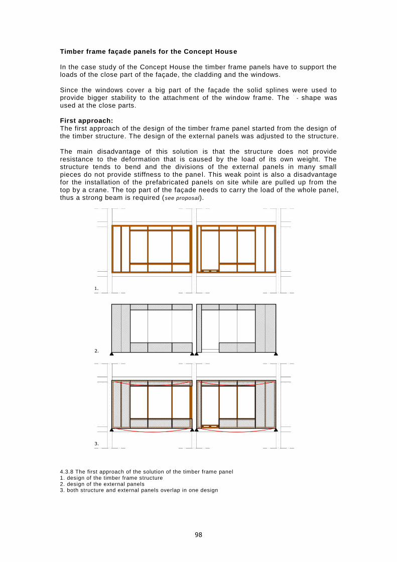
98
Timber frame façade panels for the Concept House In the case study of the Concept House the timber frame panels have to support the loads of the close part of the façade, the cladding and the windows. Since the windows cover a big part of the façade the solid splines were used to provide bigger stability to the attachment of the window frame. The - shape was used at the close parts. First approach: The first approach of the design of the timber frame panel started from the design of the timber structure. The design of the external panels was adjusted to the structure. The main disadvantage of this solution is that the structure does not provide resistance to the deformation that is caused by the load of its own weight. The structure tends to bend and the divisions of the external panels in many small pieces do not provide stiffness to the panel. This weak point is also a disadvantage for the installation of the prefabricated panels on site while are pulled up from the top by a crane. The top part of the façade needs to carry the load of the whole panel, thus a strong beam is required (see proposal). 4.3.8 The first approach of the solution of the timber frame panel 1. design of the timber frame structure 2. design of the external panels 3. both structure and external panels overlap in one design

99
Proposal: The weak point of the first approach was the starting point for the proposal. The design of a beam at the top of the panels is essential for their installation and the bearing of their own weight. The beam is a continuous unit, without hinges that crosses all the width of the façade and transfers the loads directly to the columns. The type of the beam is a hollow rectangular which is reinforced by internal - shape supports that are aligned to the vertical timber splines of the frame. Since MDF that was proposed as external panel is produced until 3m length other materials like plywood are potential solutions for the proposal. 4.3.9 Beam at the top of the façade panel At the first panel (window in the middle) two horizontal zones, on top and at th e bottom of the window that can be used continuously from column to column are used as beams. Between the beams vertical splines contribute to the stability of the panel and support the window frame. The second panel (door for access to the balcony) cannot have a continuous beam at the bottom, thus a different approach is made. Diagonal connections are used to keep the structure stable.
4.3.10 Proposal for the structure of the timber frame panels. The beams give stiffness to the structure and prevent deformation.
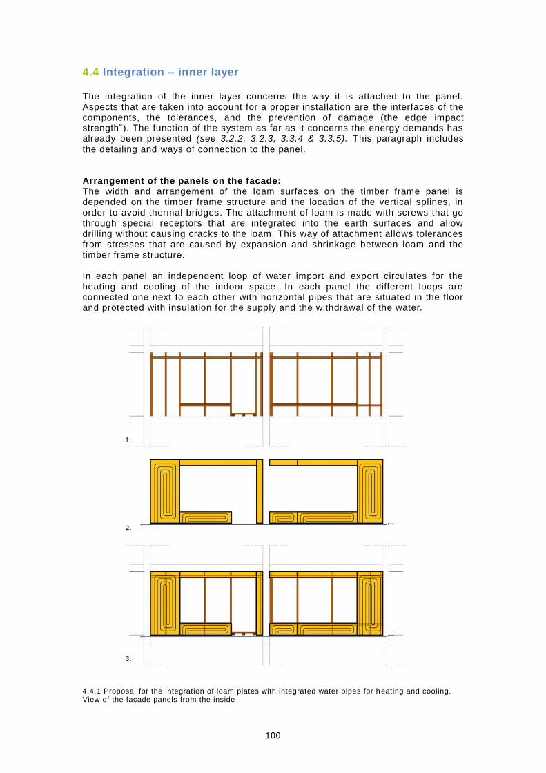
100
4.4 Integration – inner layer The integration of the inner layer concerns the way it is attached to the panel. Aspects that are taken into account for a proper installation are the interfaces of the components, the tolerances, and the prevention of damage (the edge impact strength”). The function of the system as far as it concerns the energy demands has already been presented (see 3.2.2, 3.2.3, 3.3.4 & 3.3.5). This paragraph includes the detailing and ways of connection to the panel. Arrangement of the panels on the facade: The width and arrangement of the loam surfaces on the timber frame panel is depended on the timber frame structure and the location of the vertical splines, in order to avoid thermal bridges. The attachment of loam is made with screws that go through special receptors that are integrated into the earth surfaces and allow drilling without causing cracks to the loam. This way of attachment allows tolerances from stresses that are caused by expansion and shrinkage between loam and the timber frame structure. In each panel an independent loop of water import and export circulates for the heating and cooling of the indoor space. In each panel the different loops are connected one next to each other with horizontal pipes that are situated in the floor and protected with insulation for the supply and the withdrawal of the water.
4.4.1 Proposal for the integration of loam plates with integrated water pipes for h eating and cooling. View of the façade panels from the inside

101
The size of the elements depends on the two factors that were mentioned above, the timber frame structure and the integration of water pipes. The more surface one element occupies and the more water pipes can be integrated in one element the less material and time for installation is needed. This of course creates other problems like the increase of the weight of the elements that might delay the time of installation. Since the preparation of the inner layer is prefabricated, the use of machineries for lifting the components is considered to solve that problem. For the final design of the components this factor should be taken into account. In case the big elements (2.88x1.32m) are not possible to be installed, the components can be designed with less height and the top part can be covered with loam panels without water circulation. The width though which is oriented by the timber frame structure creates a limitation, but in the case study the t imber frame structure divides the distance of the width of the loam element, thus it is possible to install smaller components of loam surfaces. The water loops become shorter and this also improves the effect of the warm water to heat up the indoor space (no heat is lost on the long loop). The first situation (3.1) is used at the case study.
4.4.2 Alternatives for the reduction of the sizes of the loam components and integration 1. limitations in width
2. limitations in height 3. combination of both

102
Attach the inner layer to the timber frame structure: The prefabricated panels of loam are attached to the vertical splines of the timber frame structure. The panels need to overlap with the t imber frame vertical splines at a minimum distance of 15mm. This is an aspect that affects the width of the vertical timber splines. A minimum of 70mm is required so as the nails are screwed towards the center. Screws that are connected towards the edge of the timber frame splines are likable to detach and trim the edge of the timber.
4.4.3 horizontal section showing detail of the attachment of the loam panels to the timber frame structure Installation of the pipes for the inlet and outlet of water: The connection of the water loops within the panels is made through pipes that are placed in the floor. The installation is made on top of the wooden structure of the floor, without affecting the design of the façade that needs to overlap with the floor structure to take the wind loads. The pipes for the supply of the loops are positioned so as they are accessible for maintenance and installation. This is made by using grills for the finishing of the floor on top of the pipes. The grills can be removed easy and allow some heat to go into the room. Below the pipes the floor is covered with a water prof layer to prevent the wood to rot in case condensation or leakage occurs on the pipes.
4.4.4 Proposal for the connection of the timber frame panel with integrated water pipes
*3D renders present an overview of the main steps in the prefabrication of the façade panel
(appendix A10)

103
4.5 Integration – outer layer
The design of the system for heat collection at the outer layer of the façade (see 3.2.4) – ceramic tiles with integrated copper pipes, is more complex than the typical cladding because it is consisted of two components (the ceramics and the pipes). In this section alternatives of the integration of the components o f the outer layers are presented considering the possibilities in the production of ceramics (shape, dimensions), the protection of the copper from the exterior environment and the aesthetics of the façade. Brief link to the ceramic tiles and supportive substructure: Before presenting the alternative concepts a short presentation of basics for the detailing of the cladding is presented with a brief mention at dimensions of standard ceramic tiles and ways of support to substructure are presented. Ceramic tiles: For the understanding of the design, the dimensions that are usually used for ceramic tiles are mentioned: The thickness of massive tiles is generally 8mm. Extruded tiles with hollow sections are produced with widths starting at 150mm. The length is cut to demand, but mostly about 300mm. Larger sizes are becoming popular at which the width is limited by the size of the extrusion machine and the length is free up to 1800mm (Boer, 2006). In the extrusion process ridges can be made and used for the f ixing on an aluminum substructure. 4.5.1, 2 dimensions of ceramic components that are used on facades (faveton.com) Supportive rails: For the support of the cladding on the façade aluminum rails are used. The rails are connected to wall brackets which are screwed on the vertical splines of the timber frame structure. The rails that are usually used for cladding are vertical or they generate a grid with combination of horizontal and vertical rails. Since the construction on which the cladding is supported is a beam and column structure, horizontal systems are used in which the primary profile is mounded horizontally on the wall brackets. Between the brackets and the construction wall, thermal separation elements can be used in order to avoid thermal bridges. 4.5.3,4 Cladding systems. Vertical (left) and horizontal (right) (retco.ro/index.php/manufacturer/downloadPdf/title/allface/fid/3 – allface.com)

104
4.5.5,6,7 Horizontal cladding system. 3D visualization (left), horizontal detail of the connection (middle) and thermal separation elements (right) (retco.ro/index.php/manufacturer/downloadPdf/title/allface/fid/3 – allface.com) Water supply and installation of pipes behind the façade The circulation for the supply of water pipes at the external layer is installed behind the cladding, thus a good insulation is required so that the collected heat is not lost. The material of the pipes in the ceramics is copper (see 3.2.4) but the material of the pipes for the water supply can be polyethylene (PE) like the one that is used at the inner layer. The circulation of the water is vertical for the ease of supplying it on all over the height of the façade. In the case study the water pipes for heat collection are used only at the first panel of the south façade (window). The south façade which leads to the balcony is not used for solar collection because of the recession of the façade which keeps some parts shaded. 4.5.8 water supply at the outer layer
The finishes of the ceramics that are in inclination are hidden behind small plates that are extruded to the front of the ceramic cladding and provide space for the installation of the water pipes as well.

105
4.5.9 installation of water pipes behind the ceramic cladding
Alternative systems for the integration of copper pipes into ceramic panels
The design of the ceramic tiles for the case study is more complex than the standard systems that already have been used (see 2.7.4) because of the integration of copper pipes for heat collection from the sun. Here alternatives of different ways in which the pipes could be integrated are presented. The criteria for the design of the alternatives were based on the possibilities in production of the ceramic tiles, on the less use of water pipe installations behind the façade and on the maximum prefabrication of the elements. 4.5.10 schematic drawings of alternatives for pipe integration into ceramic tiles at the outer layer of the façade. The integration of pipes in bigger ceramic elements (the maximum is approximately: 1800*500mm) is considered more efficient because less time is spent during the installation and prefabrication. The extension of the system can be vertically and horizontally. For the vertical expansion a standard connection between pipes is used but for the horizontal between two ceramic elements the connection is more complex because it affects the aesthetics of the façade and the protection of the pipes, thus is studied more extensively.

106
4.5.11 connections between ceramic elements with integrated pipes. Horizontal connections (left) Vertical connections (right). A combination of both horizontal and vertical connections is also possible on a façade. Alternative_1: At the first alternative the production of the ceramic component is made by extrusion. The water circulates in each row independently and goes out at the other side of the ceramic.
4.5.12 schematic principle of concept and components for alternative_1 This solution has an advantage for the production of the ceramic because the shape is created in one phase (extrusion). Extrusion has the advantage of shaping the perforations along the panel for the integration of the pipes and the ridges for the installation on the fixing rails at ones. One disadvantage is that the heat up of the water that circulates into the façade does not make a loop big enough to heat up before it is stored in the ground. This might not be a disadvantage if at the system many horizontal connections were used, but in the case of the Concept Study it cannot be used in a flexible way because the façade is interrupted by windows and doors for access to the balcony. Another disadvantage is the numerous pipes that have to be connected separately at the inlet and outlet of water at the vertical pipes and the insulation that need to cover all those connections to prevent loss of heat.

107
Alternative_2: At the second alternative the production of the ceramic component is made by extrusion as in the first alternative. The water circulates continuously in the ceramic panel with the outlet being at the same side as the inlet. The part of the pipes where the loop takes the turn is made outside of the panel.
4.5.13 schematic principle of concept and components for alternative_2 This solution combines two advantages. The one is the ease in the production of the ceramic element and the second is that the loop is concluded in one element. This means more time for the water to heat up and less installations for the vertical water pipes. The turn of the copper pipes by 180° happens outside of the panel. It is a relatively small part of the total length and can be covered with insulation to retain the heat. The layer of insulation that protects the copper pipes can be prefabricated by attaching it to the panel. This component can be reused.
Alternative_3: At the third alternative the production of the ceramic component is more complex. The water circulates continuously in the ceramic panel and the outlet is from the same side as the inlet. The loop of the water is completely integrated into the ceramic element.
4.5.14 schematic principle of concept and components for alternative_3 The part on which the pipes are integrated is made by compression. The space for the pipes is engraved at the back side of the panel. The pipes are placed and covered with another ceramic panel which is extruded w ith ridges for the connection to the fixing rails. The two ceramic panels are glued and a reflective thin layer behind the pipes radiates the heat into the pipes. This component is not indicated for reuse.

108
Horizontal connection of ceramic elements: When the ceramic panels extent vertically, the connections between the tubes are typical connections that are covered with insulation to avoid heat losses. The installation can be made at the space in front of the columns where the two facades meet. When the ceramic panels extend horizontally the connection is made at the front side of the façade. The tubes inside the ceramic panels can connect horizontally with a double ended tube. The gap that is created by the connector should be covered to prevent heat losses. A rubber that covers all the width of the ceramic tile is the most time effective solution. From aesthetic point of view it gives continuity to the connection and makes it less obvious. The horizontal connections are time consuming during construction because all the small tubes that are integrated into the panels have to be connected individually.
4.5.15 horizontal connection between two ceramic plates with integrated pipes 4.5.16 double ended tube (top left) (ec21.com) Possible solutions for the Concept House Both alternatives 2 and 3 could be used for the Concept House. Both are integrated almost in the same way and the only difference is the ending of the panels and the finishing details (the alternative 2 has insulation that need to be hidden behind tiles but the alternative 3 can be aligned with a corner tile). 4.5.17 finishing of ceramic tiles for alternative_2 &3

109
As mentioned above (see Water supply and installation of pipes behind the façade )
only one part of the façade of the case study is used for heat collection. The position of the windows also affects the components and the water circulation. Different designs are made with the window in the middle and the side. The most efficient design is the one with the window at the side because fewer pipes are needed. This means less material, less time in installation and easier installation since more space is available for the installation of the pipes. When the window is in the middle, pipes are installed at both sides of the panels (see 4.2).
4.5.18 comparison that shows how the position of the window affect the installations for water circulation at the outer layer
Proposal For the proposal, the alternative_2 is chosen because it is easier in the production of the ceramic tiles, it is prefabricated and is more flexible in case of reuse compared to the other two alternatives. The design takes into account the availability in the market and the dimensions. Although they vary in length and width the thickness of the profile which is extruded has a minimum of tolerance which is used in the case study as well. One type of extruded profiles is the one with perforations and ridges at the back side of the tile that provide receptions for the aluminum fixings. The weight of the pipes and water although might increase the weight so much that the dimensions of the ceramic plate should change. The perforations are usually rectangular with rounded corners. For the integrati on of pipes the perforations are circular. The thickness of the ceramic that separates the perforations is 4mm which means that the pipes for heat collection can be placed one very close to the other. At one panel the more water can heat up the more

110
energy is stored to the ground in order to be used during winter for heating. On the other hand this makes the panel heavy and the turns of the pipes very small, thus the water circulates every two perforations. The size of the panel is the maximum in length so as to avoid the horizontal connection and in width and make the installation quicker and the connections between the vertical pipes fewer. 4.5.19 section and front view of the ceramic components with integrated pipes The arrangement of the ceramic plates as mentioned at the comparison between the two cases (window at the middle and at the side) is more efficient when it is placed on one side of the façade because it requires fewer installations of vertical pipes.
4.5.20 Proposal for the integration of ceramic plates with integrated water pipes for heat collection from the sun

111
4.6 Construction and support to the structure So far the focus of the integration was on the components to the façade panel. The last part of integration deals with the integration of the whole façade panel as a prefabricated unit to the structure of the Concept House. The structure of the façade should comply with some basic requirements in order to be realizable. Those are: 1. bear of the loads (loads of its own weight and wind loads) 2.air tightness, 3.water tightness, 4.protection from thermal bridges and 5.tolerances in extension and shrinkage. The overall design of the façade panel with vertical and horizontal section as well as possibilities of attaching it to the timber frame structure are presented here. Support to the structure In the case of the Concept House there are some restrictions that are taken into account for the design of the façade. The façade should be supported on massive timber columns and not on the floor and should be installed as a prefabricated unit. Those restrictions lead to two main decisions: 1.The prefabricated panels are installed from the outside and are lifted by a crane and 2.The pane ls cannot be rested on the floor. For the support of the façade panel, the bear of loads and the way of positioning the panel on site are of main importance. Some assumptions on which the design is based are summarized here: The wind loads (horizontal force) pushes the façade towards the structure, thus a support from the structure should compensate the load on the connections, which practically means that the façade panel should overlap with the floor or columns. The loads of the weight of the panel would be transferred to the connections that support the panel to the columns. This load could be compensated by some supports (noses) on the columns on which the panel is rested. This solution could improve the prefabrication stage. For the tolerances of stresses distances should be kept between the panels and each panel should be supported independently. Alternatives for the attachment to the structure: The way in which the panel is attached to the frame affects in many ways the structural behavior of the panel. The panels should be attached in a way that provide sufficient space for the fixing of the connections, be optimal for safe and quick installation on site, and bear loads and tolerances. The pros and cons of four alternatives contribute into reaching a conclusion for the final choice. As a result, the second option that overlaps partially on the floor and columns that take the wind loads and at the same time keep distance from the adjacent panels to provide space for the fixings and the support of a nose during installation is chosen. 4.6.1 point where four façade panels meet

112
4.6.2 comparison between the four alternatives. The second is chosen as more advantageous
4.6.3 Second alternative for the panel More alternatives are proposed for the design of the noses. First is that the nose is made of wood that is attached to the structure. This solution has the disadvantage of making the design of the structure more complicated and does not have toleran ces. The wood might also become weaker due to wear. Both bottom and top panels can be supported on the wooden nose. The second is a steel component that provides support only to the top panels. The last approach (the cross) is a solution that provides support to all four panels that meet at that point. The design of the component for the fixing and stabilizing of the panels is towards this direction. 4.6.4 Alternatives for the design of the nose on which the panels would be rest in order to make installation easier. From left to right: wood support, steel support for the top panels and cross support for the stability of all four panels

113
Proposal for the support to the structure
The installation of the panels is made from the outside with a crane. The panel is lifted from the top (beam) and supported on the structure from its (vertical) sides. The panel is bolted on several points on the structure. It could be all over the height or at some parts. This decision depends on the structural ca lculations. Practically this means that all the weight of the panel will go on the bolts. The more the bolts are the better the distribution of the weight, but this decision makes prefabrication and installation, more complicated (more working time on site and more possibilities for accidents). The design of the components for the support of the panel before this is bolted on the sides would make the process easier because the panel would be already stabilized on place and it would take part of the vertical loads, thus fewer bolts would be needed to bear the loads of the panel. These components cannot substitute the vertical connections even if they can bear all the load of the weight, because pressure on the structure should be forced to keep it airtight. The component is designed in such a way that the horizontal steel plate takes the vertical loads of the panel when it is left there to “rest” before it is bolted. After the bottom part of the panel is fixed on place, the panel tends to lean towards the front (outside), thus extra steel plates are bolted at the top part to keep the panel stable on the façade. The bolts do not penetrate the panel, thus no thermal bridges occur at the corners. 4.6.5 Stages in which the panels are stabilized on the structure (from left to right) 1. Connection between the structure and the floor 2. The steel component is bolted on the structure 3. The first floor of the panels is put in place 4. The top part of the panels is stabilized to prevent from leaning towards the front of the façade 5. The panel of the top floor is put in place
4.6.6, 7 Front view of the timber frame panels on the structure and detail

114
Connections along the height of the panel
The connections along the vertical sides of the façade panel that take the main part of the loads and keep it air-tight are presented here focusing on the problems that were encountered during the design process. The given situation from the Concept House is a width of 300mm and vertica l solid timber columns of 90mm in each side. The target is to design the connection of the façade panel on this situation while keeping the connections air-tight, avoiding the thermal bridges and locating the bolts in the middle of the solid timber frame columns. 4.6.8 The alternatives and possibilities of connections that were examined (clockwise from top left) 1. fix from the inside, problem of air-tightness and thermal bridges 2. align the bolts to the center of the columns, problem of air-tightness and no support from wind loads 3. make airtight, bolts not aligned with timber columns 4. suggestion: increase the width of the solid timber columns to align the bolts at the c enter
For the Concept house it is suggested an increase in the width of the solid timber columns that are used for the support of the Façade. The material for the connections is suggested to be steel. The weight of the panels is so heavy that aluminum connections are estimated not sufficient to carry the loads and sustain in time.
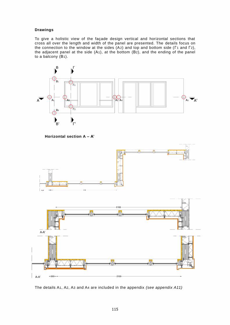
115
Drawings To give a holistic view of the façade design vertical and horizontal sections that cross all over the length and width of the panel are presented. The details focus on the connection to the window at the sides (A2) and top and bottom side (Γ1 and Γ2), the adjacent panel at the side (Α1), at the bottom (Β2), and the ending of the panel to a balcony (Β1).
Horizontal section A – A’ The details A1, A2, A3 and A4 are included in the appendix (see appendix A11)

116
Vertical Sections Β – B’ and Γ – Γ’
The details B1, B2, Γ1 and Γ2 are included in the appendix (see appendix A11)

117
5. Results and Discussion The results are evaluated in regard to the original hypothesis and research question. A short review of the first assumptions and questions that needed to be answered and whether they were is discussed in this chapter. As a concluding chapter of the master thesis, the steps that were followed are presented in the form of a summary to give a holistic view of the plan. The advantages and disadvantages of the proposed system, improvements, suggestions for the Concept House and further research are proposed.

118
5.1 Evaluation of the results Hypothesis and method The first assumption that earth could be integrated as an alternative material to the timber frame panel which is used broadly in prefabricated facades in the Netherlands and improve the indoor climate and overall durability using principles of sustainability, was tested through several steps. The first step was the study of relevant literature and visit to brick plants . Earth was studied in its backed (ceramics) and unbaked (loam) state. In each state the material have different properties that were used optimally for the Concept House façade. They were proposed for different layers in the façade panel the inner and the outer. Based on the literature study a comparison between the two materials which is summarized on the table helped in the final decision. 5.1.1 Comparison between ceramics and loam about production and performance in regard to sustainability
The crosses (+) in the table are placed under the material which is more advantageous for each property in production or performance. From the literature study we draw the conclusions that loam is a 100% natu ral material which has many advantages regarding sustainability principles. During its production the demands in embodied energy and toxic emissions are not very high in comparison to most of building materials (see appendix A1). It is a raw material that can be used in its initial state after soaked in water. During its performance it is also sustainable since it contributes in the improvement of the healthy conditions in the interior by regulating the levels of relative humidity and retaining heat in its mass (see 2.6.2). Ceramics on the other hand demand a lot of energy for their production but endure in time and the harsh conditions of nature (rain, sun, snow). They are recyclable and retaining their strength can also be reusable. It is a material broadly used in all different kind of climates. Their big advantage is the corrosion resistance and
su
sta
inab
ility
production ceramics loam
toxic emissions
( + ) (+ + + )
embodied energy
( + ) (+ + + )
reusability
( + ) (+ + + )
recyclability
( + ) (+ + + )
performance
passive system
( + + ) (+ + + )
thermal mass
( + ) (+ + )
regulate humidity
( + ) (+ + + )
corrosion resistant
( + + + ) (+ )

119
thermal mass. They do not decay under big amounts of sun radiation or rain water (see 2.7.2). Based on those conclusions the decision was made: Loam was chosen for the inner layer as a 100%natural material, which regulates the levels of relative humidity and has big thermal mass which is advantageous for passive heating. Since sunny days during the winter are not very common in the Netherlands, thermo active building systems (TABS) were studied as a solution to provide heating by radiation through the earth walls. The design of the façade can affect the performance of thermal mass at the inside. The design of the sun shading allows the sun light to reach the interior of the room during winter and block it during summer. The design of openings should have a relatively big percentage over the total area of the façade. At the Concept House the case study which was the design of a south façade required open ings with area 40-50% of the total area of the façade (see 2.4 and 4.2). In the Netherlands many days in winter can be cloudy and the thermal mass can only store the heat that is produced from the inside of the room (people, equipment). Active systems (lik e thermo-active building systems) can improve the performance of the thermal mass by radiating heat directly through the mass (see 2.5). Ceramics, as a no corrosive material that resists outdoor harsh weather conditions were chosen as a cladding for the façade that could be also used for heat collection during the summer, due to the thermal mass of the material. The second step was the study of the two standard systems that are used broadly in the Netherlands at the moment, the insulated cavity wa ll and the timber frame panel. The insulated cavity wall is built on site and the timber frame panels are a prefabricated system. From the two systems lists of advantages and disadvantages were formed in order to contribute in the formulation of the targets for the new system. The most important advantage of the insulated cavity wall is the thermal mass and the from the timber frame panel the prefabricated component façade. The merge of those two would lead to a transition from traditional building to fully prefabricated panels. That was the basis for the proposal of the new façade system. The third step was the proposal of the function of the façade system with components and sub-components in the layers. The function of the system is directed to the concept of zero energy housing. Loam with integrated water pipes for heating and cooling is designed to save energy by sustaining sufficient thermal comfort indoors. And ceramics on the cladding with integrated copper pipes that collect heat is designed to generate energy that is provided to the inner layer. The heat could be collected during the summer, stored in the ground and used during the winter. There are three steps in this loop: 1. the energy collection on the outer layer of the façade, 2. the energy storage in the ground and 3. the energy radiation through the inner layer to the inside (see 3.2.1). The proposal of the façade system already involves the function of two layers, the outer and the inner that together contribute to the zero energy house. The target for the inner is to improve the indoor climate with less energy consumption and for the outer to collect enough energy to cover the needs of the inner layer. In order to have specific results and lead the research to useful conclusions one of the two layers, the inner was studied more extensively. The outer layer is suggested as a concept idea which involves also a proposal for the design of the components. The fourth step was the comparison of water pipe systems that already exist and a visit to a construction site. The visit to the construction site was very useful because a product which is already available on the market was noted. The product is prefabricated panels made of loam with integrated water pipes (see 3.2.3). The product was evaluated though a comparison with other systems (water pipes-

120
capillary mat) and finally was chosen since it was advantageous for the project (see 3.2.2). The advantages are that it is prefabricated, is an integrated solution and it is installed very easy to the construction. Some things to question is the thickness of the panel (35mm) which might not have the effects of thermal mass that was assumed at the hypothesis and the density of loam. Those two aspects were evaluated through the literature study (see appendix A2 and appendix A7) and tested through CAPSOL (see 3.3.3). The fifth step was the test of the building physics behavior of the inner layer. The study started with hand calculations (see 3.3.2) to have an idea for the heating and cooling demands in energy and continues with the input of the model in CAPSOL (see 3.3.3) and the test with computational tools (see 3.3.4). The information for the input in CAPSOL included a study in the function references (see 3.3.1) that describe the situation in the examined room (target temperatures, internal heat production, ventilation fold) and a collection of the data for the materials that are proposed by the Concept House (see appendix A8), their properties (density, heat conduction coefficient and specific heat capacity). The model was tested in winter and summer. Several calculations were made in order to find the most optimal solution that would keep the comfort levels to the indoor at a satisfactory level while consuming the less possible energy. The results of the proposed model were compared in different thickness and density to confirm the decision that was taken based on the literature study and that the choice of 0.035m thickness and 1600kg/m³ density for loam was correct (see appendix A9). The model was tested with other systems (same façade but heating air, insulated cavity wall and timber frame panel) to reach more clear conclusions. The final conclusions are presented here:
5.1.2 Results for winter. y axis: power in kWh and x axis: different wall and heating systems
5.1.3 Results for summer. y axis: power in kWh and x axis: different wall and cooling systems
The first obvious results is that the winter period is the one which demands much more energy that the summer period.

121
Calculations for winter situation-results: As seen in the graphs the system works efficient in the winter if it is compared with the insulated cavity wall and the timber frame panel. But when it is compared with the different heating system (same model with layers and thickness but providing heat directly to the indoor air and not by radiation through the layer of loam) the results are not as satisfactory. The direct heating of air seems to have more quick effect in the space but it also needs more air changes and natural ventilation, thus the results in CAPSOL do not simulate exactly the real situation. The heating devises also need more maintenance and cleaning. In the case of the new system, the energy consumption can be less when heated water is used from the aquifers. So the results can be improved. Calculations for summer situation-results: The results of the summer situation were as expected since the direct cool of the air has a quicker effect in the reduction of the temperature levels indoors. The results show that the proposed system consumes more energy but it has more advantages compared to the green gasses that the air condition emits to the atmosphere. When water from the aquifers is used the energy consumption is less. The calculations in CAPSOL show that even with more power supply the results do not change much, with less or even non the differences are not extreme at the inside temperature. Although, the cool load improves the indoor climate, condensation might occur on the surface when cooling is provided from the walls but this is a rare case so the system is considered appropriate for cooling. Improvements: The results of winter could be improved when: 1. the thickness of the insulation layer is increased 2. the TABS are installed on the inner walls and not on the facade so as the heat is not lost to the exterior but used for the heating up of the adjacent rooms/ apartments. The first solution would increase the weight of the façade panels so the second is suggested as more optimal. The cooling performance would be improved with passive cooling with night ventilation and more use of the sun shading system from even lower temperatures (from 22°C to 19°C). Since this might be difficult to control by the users an automatic system for the function of the sun shading could be used. To prevent condensation the cooling load could be reduced from 2000W to 500W. With that change the temperatures on the wall remain above 20ºC and the energy consumption drops to 105.7kWh. The levels at the indoor temperature do not provide the comfort levels that the higher cooling load provides but improve the results that the passive cooling can offer. 5.1.4 Reduction at the power supply during summer, reduces the temperature on the s urface of the wall to avoid condensation. The energy consumption also drops to 105kWh for the summer period.

122
The last step was the design and optimal integration of the components of the system to the case study of the Concept House. There were suggestions for all the components that compose the prefabricated timber frame panel. The proposals include the design of the timber frame panel (see 4.3), the design of the loam panels with integrated water pipes (see 4.4), the exterior layer of the cladding with the ceramic panels and the integrated copper pipes (see 4.5), and finally the ways to attach to the structure and optimal ways of prefabrication for ease in installation (see 4.6). The integration of the inner layer was oriented by the restrictions of size and weight. Size, specifically width had to be aligned with the timber frame structure. The weight of the panels affects the transportation and manipulation during installation. The size of the panels also affects the performance. The bigger the loop of th e water pipes within a panel the more heat is lost on the way. Shorter loops perform better. The integration of the outer layer was dependent on the size of the ceramic panels and the ease in the installation of the water pipes. The pipes were chosen to be integrated in one ceramic element, because this would make easier the installation and supply of the water pipes. The size of the ceramic panel is within the sizes that are available already on the market. The integration of the pipes in the outer layer affected the original design of the opening that was located in the middle of the panel. The water circulation is easier when the pipes run from one side of the façade (fewer installations, less material used, more efficient because water makes a bigger loop and has time to warm up). The design of the water supply system brought up also some other questions about the efficiency and practical use. Since the water needs to be drained out during the winter to avoid frost, at the summer time when is set to circulation the pipe system needs to be controlled (probably manually) in order to exhaust the air that is kept in the pipes. This should be done from the top, which could be the roof. Practically for the design of the system this means that all pipes should be accessible for this reason and installation of pipes is easier when it is aligned (installations in recessions that are created by balconies are not recommended). As for prefabrication, the ceramic panels with integrated pipes have the disadvantage that should be installed after the panels are attached to the structure. The ceramic panels with the copper pipes can be already prefabricated but the attachment to the structure has to be done on site. In this sense this solution is not the best option for fully prefabricated panels.
5.2 Suggestions for further research
The proposal of the function of the outer layer as heat collector is proposed as a concept idea. The use of the façade as a heat collection has good prospects in the concept of the zero energy houses since it could contribute in a more sustainable solution but in combination with collectors on the roof which usually are more powerful (like solar tubes). This solution is worth to explore since the area of the facades (in m²) can compete the area of the roof. For more accurate conclusions, the amount of solar energy that is prospecting on the façade, the heat absorption of the material that hosts the water pipes, temperature of the water when it enters the loop and when it is stored i n the ground could be calculated. Those tests would include experiments with samples of materials at the outdoor environment that would cover the amount of days that is suggested for use.

123
6. Conclusions The conclusions summarize the main principles of the proposal for the Concept House façade. Reuse and recycle:
1. Loam is a 100% natural material that can be reused just by soaking it to water.
2. Ceramics is no corrosive material and its components that are used as
cladding at the external layer of the façade can be reused.
Production & prefabrication:
3. Loam and ceramics can be produced industrially and create a standard system which can be used for low cost housing.
4. The components of loam and ceramics that are proposed for the Concept House can be already be prefabricated with the water pipes integrated.
Indoor climate:
5. Loam at the inner layer of the façade improves the indoor climate by
regulating the levels of relative humidity.
6. Loam can be used for passive heating because of its big thermal m ass.
7. The integration of TABS into loam increases the heat that is stored in its mass. The advantage over heating the air is that less natural ventilation is required to change the heated air, thus more energy is saved to the interior.
8. The thermal mass contributes into avoiding extremes in the temperature at
the inside during the whole year. The increase in the density of the material contributes to that.
Façade system:
9. The combination of the inner layer with water circulation for heating and the
outer layer for heat collection can contribute to the concept of zero energy houses.
10. The temperature of the circulating water in the pipes for cooling the interior should not exceed the levels that cause condensation on the surface of the wall.
11. Ceramics used as a cladding with integrated water pipes could be a good potential for heat collection because of its thermal mass.
12. The use of water for heating and cooling from the aquifers reduce the energy consumption of the system.
Integration and construction:
13. The components of loam can be integrated on the timber frame panel before the installation on the construction.
14. The ceramic elements for the cladding should be installed after the attachment of the panels to the construction is completed.

124
► Acknowledgements I wish to thank all those who contributed in the realization of my master’s thesis. I would like to thank my supervisors Arie Bergsma and Arjan van Timmeren for their guidance and enthusiasm in this project. I would also like to thank all the Professors who helped me out as external advisors, including Tillmann Klein, Peter van den Engel, Roel Schipper, and especially Regina Bokel who helped me extensively with the calculations and the input in CAPSOL. In addition, I would like to thank my fellow student Anita van der Brugge and Frederik Winterwerp. Both helped me to arrange a visit in a construction site that was very useful in my research. I would also like to thank Tomas Pijnenborgh for accepting me in the construction site. Lastly, I would like to thank my classmates and friends for their companionship and friendship during these two years in TU Delft. And to my family, I would like to express my deep gratitude for their constant support and encouragement.

125
► Literature Books 1. Allen E. (1993), Architectural detailing – function, constructubility, aesthetics , John Wiley & sons, USA 2. Ashby M., Shercliff H., Cebon D. (2007), Materials engineering, science, processing and design, Butterworth-Heinemann, Italy 3. Berge.B (2009), The Ecology of Building Materials, Architectural press, Italy 4. Boer H.R. (2006), Introduction Facades II for foreigh students CT4211,
Technical University Delft
5. Boubekeur S. (CDI), Houben H. (CRATerre-EAG) in Doat P., d’Ornano S.,
Douline A., Garnier Ph., Guillaud H., Joffroy Th., Rogassi V. editors (1998), Compressed earth blocks – standards, CDI and CRATerre-EAG/ODA, Brussels, Belgium
6. CRATerre-EAG (1991), Basics of compressed earth blocks, Deutsches
Zentrum für Entwicklungstechnologien, Eschborn, Germany
7. Hens H. (2007), Building Physics – Heat, Air and Moisture. Fundamentals and Engineering Methods with Examples and Exercises, Ernst & Sohn, Germany
8. Knaack U., Klein T., Bilow M. (2008), Imagine 01, 010 Publishers, Rotterdam
9. Knaack U., Klein T., Bilow M., Auer T. (2007), Facades: principles of
construction, Birkhauser, Basel
10. Linden van K. (2006), Bouwfysica, sixth edition, Utrecht
11. Minke G. (2009), Building with earth, design and Technology of a Sustainable Architecture, Birkhauser, Germany
12. Neufert E. and P. (2000), Architects’ data, in Baiche B., Walliman N. editors, Oxford 13. Oliver P. (1997), Encyclopedia of vernacular architecture of the world,
Cambridge University Press 14. Rigassi V., CRATerre-EAG (1985), Compresses earth blocks, Volume I manual
of production, Deutsches Zentrum für Entwicklungstechnologien, Eschborn, Germany
15. Ruiter A., Steenbrink I., Zijlstra E. (2005), Material skills – evolution of materials, Rotterdam 16. Vellinga M., Oliver P., Bridge A. (2007), Atlas of Vernacular Architecture of the
World 17. Yannas S. (1994), Solar Energy and Housing Design, Vol.1: principles,
objectives, guidelines , Department of Trade and Industry, London

126
Papers
1. Olesen B.W. (2010), Cooling and heating of buildings by activating their thermal mass with embedded hydronic pipe systems
2. Peter van den Engel, Regina B., Leo de Ruijsscher, (2009), Concrete core activation
3. Peter van den Engel, Leo de Ruijsscher, (2010), Concrete core activation, working principles and applications
Internet
absak.com/pdf/docs/loadeval.pdf ashanging.com baksteen.be/nl.html beka-klima.de bine.info bioclina.de
bre.co.uk bridgat.com carbonfootprint.com/energyconsumption.html claytech.de clina.co.uk
clina.co.uk
ec21.com
ecoedge.ca/images/stories//passivesolar.jpg
eliosolar.com
energysavers.gov/your_home/appliances/index.cfm/mytopic=10040 es-so.com
faay.nl faveton.com
gaisma.com
gezondbinnen.nl groenebouwmaterialen.nl iklimnet.com learn.londonmet.ac.u nbk.de passive-house.co.uk radiantcooling.org roth-canada.com senternovem.nl shop.royalvkb.com soilmoisture.com solarenergynews.net sunstatesolar.com.au sustainability.vic.gov.au swelite.nl tierrafino.com thermo-hanf.de tootoo.com wall-heating.com wandverwarming.nl wienerberger.nl wikipedia windows.lbl.gov/daylighting/designguide/section5.pdf winterpanel.com worldcanals.com yourhome.gov.au

127
►Appendix
appendix A1
(Berge, 2009)

128
appendix A2
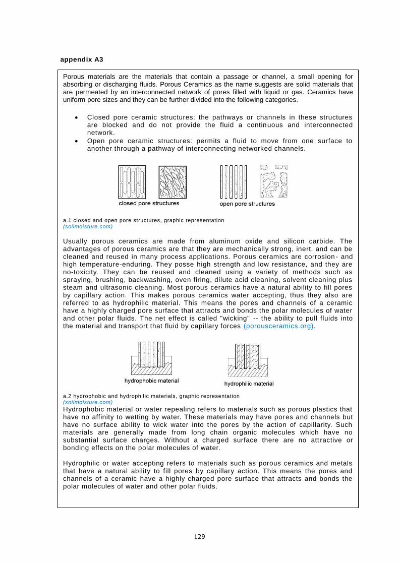
129
appendix A3
Porous materials are the materials that contain a passage or channel, a small opening for absorbing or discharging fluids. Porous Ceramics as the name suggests are solid materials that are permeated by an interconnected network of pores filled with liquid or gas. Ceramics have uniform pore sizes and they can be further divided into the following categories.
Closed pore ceramic structures: the pathways or channels in these structures are blocked and do not provide the fluid a continuous and interconnected network.
Open pore ceramic structures: permits a fluid to move from one surface to another through a pathway of interconnecting networked channels.
a.1 closed and open pore structures, graphic representation (soilmoisture.com)
Usually porous ceramics are made from aluminum oxide and silicon carbide. The advantages of porous ceramics are that they are mechanically strong, inert, and can be cleaned and reused in many process applications. Porous ceramics are corrosion - and high temperature-enduring. They posse high strength and low resistance, and they are no-toxicity. They can be reused and cleaned using a variety of methods such as spraying, brushing, backwashing, oven firing, dilute acid cleaning, solvent cleaning plus steam and ultrasonic cleaning. Most porous ceramics have a natural ability to fill pores by capillary action. This makes porous ceramics water accepting, thus they also are referred to as hydrophilic material. This means the pores and channels of a ceramic have a highly charged pore surface that attracts and bonds the polar molecules of water and other polar fluids. The net effect is called "wicking" -- the ability to pull fluids into the material and transport that fluid by capillary forces (porousceramics.org). a.2 hydrophobic and hydrophilic materials, graphic representation (soilmoisture.com)
Hydrophobic material or water repealing refers to materials such as porous plastics that have no affinity to wetting by water. These materials may have pores and channels but have no surface ability to wick water into the pores by the action of capillarity. Such materials are generally made from long chain organic molecules which have no substantial surface charges. Without a charged surface there are no att ractive or bonding effects on the polar molecules of water. Hydrophilic or water accepting refers to materials such as porous ceramics and metals that have a natural ability to fill pores by capillary action. This means the pores and channels of a ceramic have a highly charged pore surface that attracts and bonds the polar molecules of water and other polar fluids.

130
appendix A4
This clearly explains why the pore size of a porous ceramic piece is of great importance. The pore size directly affects the ceramic's air entry or bubbling pressure and hydraulic conductivity. The air entry value is the pressure at which air brakes throug h a wetted pore channel. The hydraulic (liquid) conductivity of a porous ceramic is a measure of the rate at which a ceramic material of a known thickness may conduct liquid from one surface to an opposing surface under a known pressure. The effective pore size is determined by the minimum orifice within a channel or pore. These properties that are determined by pore size are intrinsic to ceramics and to all other porous materials.
Porous ceramics offer a wealth of uses from water treatment to catalysis t o sensors. Typical uses of porous ceramics include applications in filtration (solid particulate removal), diffusion (gas-gas, gas-liquid, and liquid-liquid mixing), liquid dispersion (wicking), fluidizing/pneumatic conveying, aeration, field drainage, mea suring changes in hydraulic potentials and water tensions, and running moisture retention curves (soilmoisture.com).
Milling is the process by which materials are reduced from a large size to a smaller size. Milling may involve breaking up cemented material (in which case individual particles retain their shape) or pulverization (which involves grinding the particles themselves to a smaller size). Milling is generally done by mechanical means, including attrition (which is particle-to-particle collision that results in agglomerate break up or particle shearing), compression (which applies a forces that results in fracturing), and impact (which employs a milling medium or the particles themselves to cause fracturing). Attrition milling equipment includes the wet scrubber (also called the planetary mill or wet attrition mill), which has paddles in water creating vortexes in which the material collides and break up. Compression mills include the jaw crusher, roller crusher and cone crusher. Impact mills include the ball mill, which has media that tumble and fracture the material. Shaft impactors cause particle -to particle attrition and compression.
Batching is the process of weighing the oxides according to recipes, and preparing them for mixing and drying.
Mixing occurs after batching and is performed with various machines, such as dry mixing ribbon mixers (a type of cement m ixer), Mueller mixers, and pug mills. Wet mixing generally involves the same equipment.
Forming is making the mixed material into shapes, ranging from toilet bowls to spark plug insulators. Forming can involve: 1) Extrusion, such as extruding "slugs" to make bricks 2) Pressing to make shaped parts. 3) Slip casting, as in making toilet bowls, wash basins and ornamentals like ceramic statues. Forming produces a "green" part, ready for drying. Green parts are soft, pliable, and over time will lose shape. Handling the green product will change its shape. For example, a green brick can be "squeezed", and after squeezing it will stay that way.
Drying is removing the water or binder from the formed material. Spray drying is widely used to prepare powder for pressing operations. Other dryers are tunnel dryers and periodic dryers. Controlled heat is applied in this two-stage process. First, heat removes water. This step needs careful control, as rapid heating causes cracks and surface defects. The dried part is smaller than the green part, and is brittle, necessitating careful handling, since a small impact wi ll cause crumbling and breaking (wikipedia.com).
Firing is where the dried parts pass through a controlled heating process, and the oxides are chemically changed to cause sintering and bonding. The fired part will be smaller than the dried part.

131
appendix A5 Deformation - Extrusion
In ceramic extrusion a plastic mix of ceramic powder plus polymer additives is forced through a shaped die of the desired cross section. Following extrusion, the material is cut to length and sintered. The process produces low porosity components with good tolerances. Two basic extruder types are used: ram extrusion (similar to metal extrusion) is essentially a batch process and is used mainly for the fine ceramics with organic plasticizers. The second type is the screw-extrusion technique which is a continuous process usually used for processing of clay-based ceramics eg. for brick and pipe production. Supporting information Shapes of uniform cross section / commonly used with aluminas, clay ceramics, silicon nitride, silicon carbide etch / typical uses: bar, rod, tube, sewer pipe, brick etch / tooling cost range covers small, simple to large, complex dies Powder methods – Die pressing and sintering In die pressing and sintering, metal or ceramic powders are blended and then pressed in a closed die to form a green compact of the desired shape. The “green” compact is then sintered by heating it in a controlled atmosphere to a temperature just below the melting point to bond the contacting surfaces and particles. Components made of unusual materials or mixtures can be produced this way. The process can be suitable for any material but is mainly used for metals and ceramics. Split dies cannot be used for a variety of technical reasons thus imposing shape limitations. Ceramics can be shaped by filling a mold with loose powder and compacting it. The main microstructural evolution is the shrinkage of porosity during compaction, with each particle becoming a final grain. Powder compaction mechanisms are closely related to diffusional flow and creep. In purely thermal compaction (sintering), atoms diffuse along the particle boundaries to fill in the pores. Compaction is accelerated by imposing external pressure as well as temperature – “hot isostatic pressing” – giving particle deformation by creep. Supporting information Shape limitations: sidewalls must be parallel, undercuts at right angles to the pressing direction / process is economical for components of extremely complicated shape in which wall thickness varies over a very wide range / production rate depends on complexity of component and number of cavities. Powder methods - Slip casting In slip casting, a water based slip of the ceramic powder is prepared and powdered into porous mold. The slip must have low viscosity to flow easily into the mold. The mold absorbs some of the water and the slip forms a semi-hard layer on the mold surface. When sufficient thickness has accumulated, the remaining slip is pured out. The green casting is further dried and then sintered in the usual manner. Because of the high liquid content of the slip, large shrinkage takes place upon firing and therefore tolerances are fairly wide. Tape casting is an important variant of slip casting, used to fabricate ceramic substrates for electronic circuits. Supporting information Complex shapes with detailed surface moldings are possible. Inserts are avoided to prevent cracking. Hollow and cylindrical shapes can be made / although production rate is low and dimensional control is limited, mold and equipment costs are low, and therefore the process is economical for small quantities / uses: whiteware, pottery, large or complicated parts. (CES software)

132
appendix A6
Additives like sand and gorgo are used to give the required texture. Contrasting colored clays and grogs are sometimes used to produce patterns in the finished wares. Engobe is a clay slip, often white or cream in color that is used to coat the surface of pottery, usually before firing. Its purpose is often decorative, though it can also be used to mask undesirable features in the clay to which it is applied. Engobe slip may be applied by painting or by dipping, to provide a uniform, smooth, coating. Agatewares are made by blending clays of differing colors together, but not mixing them to the extent that they lose their individual identities. Litho are used to apply designs to articles. The litho comprises three layers: the color, or image, layer which comprises the decorative design; the cover coat, a clear protective layer, which may incorporate a low-melting glass; and the backing paper on which the design is printed by screen printing or lithography. There are various methods of transferring the design while removing the backing -paper, some of which are suited to machine application. Gold decoration is used on some high quality ware. Glaze is a coating substance which has been fired to fuse to a ceramic object to color, decorate, strengthen or waterproof it. Glaze may be applied by dry dusting a dry mixture over the surface of the clay body. Ceramic glazes generally contain silica to form glass, in combination with a mixture of metal oxides such as sodium, potassium and calcium which act as a flux and allow the glaze to melt at a particular temperature, alumina (usually from added clay) to stiffen the glaze and prevent it from running off the piece, colorants such as iron oxide, copper carbonate or cobalt carbonate, and sometimes opacifiers such as tin oxide or zirconium oxide (wikipedia).

133
appendix A7

134
appendix A8

135
appendix A9 Results for winter situation. From top left (clockwise) thickness: 0.12m density: 700kg/m³ thickness: 0.12m density: 1600kg/m³ thickness: 0.035m density: 700kg/m³ thickness: 0.035m density: 1600kg/m³
Results for summer situation. From top left (clockwise) thickness: 0.12m density: 700kg/m³ thickness: 0.12m density: 1600kg/m³ thickness: 0.035m density: 700kg/m³ thickness: 0.035m density: 1600kg/m³

136
appendix A10
2.
1.
3.
4.
5.
6.
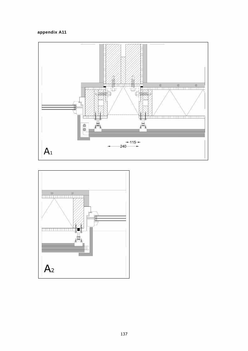
137
appendix A11

138

139

140

141