L.Uwimana Thesis - TU Delft Repositories
238
DELFT UNIVERSITY OF TECHNOLOGY FACULTY OF CIVIL ENGINEERING AND GEOSCIENCES DEPARTMENT OF BUILDING ENGINEERING Adding stories on top of the existing building by using steel structures Case study: Dillenburgsingel project in Leidschendam Master of Science Thesis By Leopold Uwimana Delft, June- 2011
-
Upload
khangminh22 -
Category
Documents
-
view
0 -
download
0
Transcript of L.Uwimana Thesis - TU Delft Repositories
DELFT UNIVERSITY OF TECHNOLOGY
FACULTY OF CIVIL ENGINEERING AND GEOSCIENCES DEPARTMENT OF BUILDING ENGINEERING
Adding stories on top of the existing building by u sing steel structures
Case study: Dillenburgsingel project in Leidschend am
Master of Science Thesis By
Leopold Uwimana
Delft, June- 2011

ii

iii
Adding stories on top of the existing building by u sing steel structures
Case study: Dillenburgsingel in Leidschendam
Master of Science Thesis By
Leopold Uwimana
Thesis committee
1. Prof. R.Nijsse, Delft University of technology, Section of Building and structural engineering
2. Ir. R. Abspoel, Delft University of technology, Section of Building and structural
engineering
3. Ing. H. J. Everts , Delft University of technology, Section of Geotechnology
4. Ing. R. Stark, Ingenieursbureau SmitWesterman, Gouda
This research is done for the partial fulfillment of requirements for the Master of Science degree at Delft
University of Technology TU-Delft, Delft, the Netherlands
Delft
June 2011

iv

v
To Marie Claire INEZA


vii
Preface
For the completion of the Delft Civil Engineering study, this thesis has been written. The knowledge gained during the Civil Engineering study had to be applied on a certain technical subject. For this thesis, it has been chosen to make an alternative structural design for adding stories on existing building by using a case study of Dellenbourgsingle in Leidschendam. The engineering office SmitWesterman of Gouda, created a structural design for a building of fifteen stories by demolishing the existing building of six stories. Thereafter SmitWesterman, wished to create another alternative by creating more stories and even cantilevering the existing building which would not be demolished. This design project was therefore done as Master project at Building section of Delft University of Technology .In this report, the first part of the thesis, a study will be done to find feasible structural concepts for the Southern Hall. The success of the thesis would not have been possible without the contribution and guidance of the examination committee. To this regard, I would like to express my sincere gratitude to my supervisor Prof.dipl.ing. J.N.J.A. Vambersky, who gave the opportunity to work on this project,. His guidance, inspiring discussion, great patience and the freedom he gave in the research helped to complete the project. I also thank Prof. R. Nijsse who took over the role of Prof Vambersky to guide me until the end of the project. Many thanks to Ir. R, Abspoel for his major contributions to the completion of this thesis. He gave most generously his time any time I need it within the sole objective of getting it right and the trouble he took to provide me with necessary instructions and to discuss my problems throughout the entire project. I am grateful to Ing. R.Stark of SmithWesterman for his tremendous contribution in providing the topic as well as the required data and various information. Furthermore, I would like to thank Ing. H.Everts for his assistance in foundation design by providing me with valuable information pertaining to the fulfilment of this research. I owe much to my Parents, my brother B. Uwamahoro, my fiancée M.C.Ineza my uncle E. Muzindutsi and the rest of my family for their long-distance encouragement and financial support during difficulty times. Leopold Uwimana Delft June 2011


ix
TABLE OF CONTENT
Preface............................................ ................................................................................................................. vii
Summary ............................................ ............................................................................................................. xv
PART 1: CONCEPT STUDY.............................. ............................................................................................XVII
1. INTRODUCTION............................................................................................................................................1
1.1. Research background........................... .....................................................................................................1 1.1.1 Technical characteristics .........................................................................................................................................1 1.1.2 Case study ...............................................................................................................................................................1
1.2 Research objectives............................ ........................................................................................................2
1.3 Problem definition ............................. ..........................................................................................................2
1.4 Research methodology........................... ....................................................................................................3
1.5 Scope.......................................... ..................................................................................................................3
2. OVERVIEW OF THE EXISTING BUILDING ............... ...................................................................................5
2.1 Environment.................................... .............................................................................................................5
2.2. Soil condition and ground water ............... ...............................................................................................8
2.3. Structural members of the existing building... ......................................................................................10 2.3.1. Walls.....................................................................................................................................................................10 2.3.2. Columns and beams .............................................................................................................................................12 2.3.3. Floor system.........................................................................................................................................................12 2.3.4. Sub- structure (foundation) composition ............................................................................................................13
2.4 Capacity of structural elements of the old buil ding. .............................................. ...............................14 2.4.1 Foundation ............................................................................................................................................................15 2.4.2. Columns ...............................................................................................................................................................16 2.4.3 Stability of the existing building............................................................................................................................19 2.4.3.1 Behaviour of in-filled frames..............................................................................................................................19 2.4.3.3 Checking the deflection....................................................................................................................................21
2.5 Conclusion on existing building.............. ..............................................................................................22
3. REFERENCE PROJECTS............................................................................................................................23
3.1 Actual design of Smitwesterrman ................ ...........................................................................................23 3.1.1 General description...............................................................................................................................................23 3.1.2 Functional concept................................................................................................................................................24 3.1.3 Structural concept.................................................................................................................................................27 3.1.4 Erection and construction method .......................................................................................................................27 3.1.5 Useful point from this project that can be used in the thesis...............................................................................28
3.2 Kennedy tower in Eindhoven ..................... ..............................................................................................28 3.2.1 General description and Functional concept ........................................................................................................29 3.2.2 Structural concept and construction method .......................................................................................................29 3.2.3 Useful point from this project that can be used in the thesis...............................................................................30
x
3.3 Hogeschool voor muziek en dans Rotterdam (HMDR) ..........................................................................31 3.3.1 General description...............................................................................................................................................31 3.3.2 Functional concept................................................................................................................................................31 3.3.3 Structural concept.................................................................................................................................................32 3.3.4 Erection and construction method .......................................................................................................................33 3.3.5 Useful points from this project that can be used in the thesis .............................................................................33
3.4 Red Apple Rotterdam............................ ....................................................................................................34 3.4.1 General description and Functional concept ........................................................................................................34 3.4.3 Structural concept.................................................................................................................................................35 3.4.4 Erection and construction method .......................................................................................................................35 3.4.5 Useful points from this project that can be used in the thesis .............................................................................35
3.5 Conclusion ..................................... ............................................................................................................36
4. STRUCTURAL SYSTEM TO BE USED IN THE CASE STUDY. ................................................................37
4.1 The design..................................... .............................................................................................................37
4.2 Vision ......................................... .................................................................................................................37
4.3 Boundary conditions............................ .....................................................................................................37
4.4 Interaction between floor framing and the bui lding function ..................................... ........................37
4.5 The design parameters (Program of requirements) ..............................................................................39
4.6 Choice of structural system. ................... .................................................................................................40 4.6.1 Factors considered in choosing structural system for the case study ..................................................................41 4.6.2 Decision on structural system to be used in this case study.................................................................................44 4.6.3 Construction techniques .......................................................................................................................................45
5. FLOOR SYSTEM ..........................................................................................................................................47
5.1 System with composite deck slabs ............... ..........................................................................................47
5.2 System made by Universal beams with precast con crete floors(Hollow core slab). .................... .....49
5.3 System with Bubble Deck floor.................. ..............................................................................................49
5.4 System with Lattice Girder Floors ( Reinforced composite floor plates) ............................ ................50
5.5 Selection of floor system...................... ....................................................................................................51
6. DESIGN ALTERNATIVES BASED ON FLOOR FRAMING SYSTE M ........................................................53
6.1 Transverse frame made of continuous girders can tilevering at each floor level ..................... ..........54
6.2 Transverse framing with one intermediate suppor t ..............................................................................60
6.3 Transverse floor framing with two or more inter mediate supports ................................... ..................64
6.4 Transverse floor framing with two concrete wall s in axis -1 and 0................................. .....................66
7. EVALUATION OF ALTERNATIVES ...................... ......................................................................................71
7.1 Summary of alternatives........................ ...................................................................................................71
xi
7.2 Decision factors (criteria) .................... .....................................................................................................71
7.3 The Multi-Criteria Analysis (MCA) .............. .............................................................................................72
7.4 Conclusion ..................................... ............................................................................................................75
PART 2: STRUCTURAL DESIGN OF THE SELECTED ALTERNATI VE.......................................................77
8. STABILITY SYSTEM OF THE SELECTED ALTERNATIVE .... ...................................................................79
8.1 Stabilizing structures ......................... .......................................................................................................79 8.1.1 Concrete Core .......................................................................................................................................................79 8.1.2 Concrete Core with old building............................................................................................................................80 8.1.3 Concrete core with one braced steel frames and old building .............................................................................84 8.1.4 Concrete core with three steel frames and old building.......................................................................................88 Lower part ......................................................................................................................................................................89 8.1.5 Conclusion.............................................................................................................................................................89
9. DESIGN OF STRUCTURAL ELEMENTS OF THE FINAL STRUC TURE...................................................91
9.1 Column design.................................. .........................................................................................................91
9.2 Spine beams design............................. .....................................................................................................92
9.2 Spine beams design............................. .....................................................................................................92
9.3 Bracing design................................. ..........................................................................................................93
9.4 Important connections.......................... ....................................................................................................94 9.4.1 Connection of columns to the old building...........................................................................................................94 9.4.2 Connection of beams to columns .........................................................................................................................95 9.4.3 Connection among beams ....................................................................................................................................96
9.5 Fabrication and erection of steel structure .... ........................................................................................96
9.6 Lateral stability of frames and beams .......... ...........................................................................................96
10. PRELIMINARY ANALYSIS OF THE FINAL STRUCTURE .... ...................................................................97
10.1 Braced steel frame ............................ ......................................................................................................97 10.1.1 First order deflection...........................................................................................................................................97 10.1. 2 Second order effect of gravity loading .............................................................................................................100 10.1.3 Effect of foundation rotation ............................................................................................................................103 10.1.4 Effect of moment due to cantilevers ................................................................................................................104 10.1.5 Conclusion.........................................................................................................................................................104
10.2 Core.......................................... ...............................................................................................................105
11. FINAL ANALYSIS OF THE FINAL STRUCTURE .......... .........................................................................107
11.1 Input data .................................... ...........................................................................................................107 11.1.1 Loading..............................................................................................................................................................107 11.1.2 Materials ...........................................................................................................................................................107 11.1.3 Spring stiffness of bracing structure .................................................................................................................108 11.1.4 Connection between girders and edge columns...............................................................................................110

xii
11.2 Braced frame modeling and results ............ .......................................................................................112 11.2.1 Deflection .........................................................................................................................................................112 11.2.2 Support reactions..............................................................................................................................................116
11.3 Modeling of Un-braced frame carrying only the gravity load ....................................... ....................117
11.4. Reduction of vertical deflection of beams... .....................................................................................119
11.4 Conclusion .................................... .........................................................................................................121
12. DESIGN OF FOUNDATION......................................................................................................................123
12.1 Location of the foundation piles.............. ............................................................................................123
12.2 Choice of type of foundation.................. ..............................................................................................124
12.3 Description of Fundex piles [29].............. ............................................................................................124 12.3.1 Application of Fundex piles ...............................................................................................................................124 12.3.2 Advantages of Fundex piles...............................................................................................................................124
12.4 Method of installation ........................ ...................................................................................................125
12.5 Pile capacity and required number of piles .... ....................................................................................126
13. CONCLUSIONS AND RECOMMENDATIONS ................ ........................................................................129
13.1 Conclusions ................................... ........................................................................................................129 13.1.1 Existing Building ...........................................................................................................................................129 13.1.2 New structure ...................................................................................................................................................130
13.2. Recommendations .............................. .................................................................................................131
REFERENCES:...............................................................................................................................................133
APPENDICES .................................................................................................................................................135
APPENDIX 1. HOLLOW CORE SLABS ...................... ..................................................................................137
A1.1 Introduction .................................. .........................................................................................................137
A1.2 Function...................................... ...........................................................................................................137
A1.3 Design information ............................ ...................................................................................................137
APPENDIX 2. LOAD ON BUILDING ....................... .......................................................................................139
A 2.1 Vertical load................................ ..........................................................................................................139 A 2.1.1 Floor slab, slab treatment and variable load ...................................................................................................139 A 2.1.2 Steel load .........................................................................................................................................................139
A2.2 Horizontal load .............................. .......................................................................................................140 A.2.2.1 Wind load........................................................................................................................................................140 A2.2.2 Allowance for imperfection ..............................................................................................................................142
APPENDIX 3. DETERMINATION OF GIRDER SECTION....... .....................................................................145

xiii
A3.1. Variable load on cantilever .................. ...............................................................................................145
A3.2 Variable load on beam part between supports.. ...............................................................................146
A3.2 The required moment of inertia................ ...........................................................................................146
APPENDIX 4. STEEL SECTION FOR COLUMN.............. ............................................................................147
A4.1 Design load................................... .........................................................................................................148
A4. 2. Estimation of column sizes .................. .............................................................................................148
APPENDIX 5: DESIGN OF COMPOSITE COLUMNS............ .......................................................................151
A5.1. Design of supporting columns in axis G, frame 1 to 7 ............................................ ........................151
A5.2. Design of supporting columns in axis C , fra me 1 to 7.......................................... .........................154
APPENDIX 6. DESIGN OF SPINE BEAM................... ...................................................................................157
A6.1 Design by additional deflection............... ............................................................................................157
A6.2 Verification of Spine by matrix frame model ... ..................................................................................158
A6.3 Checking the cross-section of the girder...... .....................................................................................158
A6.4 Checking the deflection of the girder ......... ........................................................................................159
APPENDIX 7. STABILITY ALTERNATIVES FOR THE NEW STR UCTURE...............................................161
A7. 1 Concrete core working alone .................. ...........................................................................................161 A7.1.1 Calculation of the concrete core moment of inertia ........................................................................................161 A7.1.2 Main stabilizing structure derivation equations ...............................................................................................162 A7.1.3 Check for the actual deflections .......................................................................................................................165
A7.2 Concrete core with the existing building ...... .....................................................................................166 A7.2.1 Upper part.........................................................................................................................................................166 A7.2.2 Lower part.........................................................................................................................................................167
A7.3 Concrete core with old building and one braced steel frame ....................................... ...................169 A7.3.1 Upper part.........................................................................................................................................................169 A7.3.2 Lower part.........................................................................................................................................................171
A7.4 Concrete core with old building and three brac ed steel frames.................................... ..................173 A7.4.1 Upper part.........................................................................................................................................................173 A7.3.2 Lower part.........................................................................................................................................................174
A7.5 Conclusion .................................... ........................................................................................................175
A8. DESIGN OF BRACINGS IN THE FINAL DESIGN ........ .........................................................................177
A9.CALCULATION OF HORIZONTAL DEFLECTION OF BRACING STRUCTURES IN FINAL DESIGN .181
A9.1 Braced frame .................................. .......................................................................................................181 A9.1.1 First order deflection ........................................................................................................................................181 A8.1.2 Second order effect ..........................................................................................................................................186
xiv
A8.2 Core .......................................... ..............................................................................................................189 A8.2.1 First order deflection ........................................................................................................................................189
Calculation of core ................................ ........................................................................................................189
A10. CAPACITY OF OLD BUILDING ..................... ......................................................................................199
A10.1 The capacity of basic structural elements of the existing building. ............................. ................199 A10.1.1 Foundation......................................................................................................................................................200 A10.1.2 Columns ..........................................................................................................................................................201
A10.2 Stability of the existing building ........... ............................................................................................203
APPENDIX 11. FOUNDATION DESIGN ..................... ...................................................................................209
A11.1 Load on foundation ........................... .................................................................................................209 A11.1.1 Vertical load of foundation .............................................................................................................................209 A11.1.2 Lateral loads....................................................................................................................................................209
A11.2 Calculation bearing capacity of new piles (Fu ndex piles)........................................ ......................210
A11.3 Capacity of piles in old building............ ............................................................................................215
A11.4 Required number of pile for new foundation... ................................................................................215

xv
Summary
This study intends to develop a design method of adding more stories on existing building by using a case study of construction project in Leischendam where 9-stories are to be added on existing 6-storey residential building. A low riser building is to be changed into multistory building. The state-of-art of the project was designed by the Engineering office of SmitWesterman and implemented by demolishing a section of the existing building where additional stories were constructed. The initial idea was to add 9-stories on existing 6 to form a structure of 15 story-high without demolition. Even though this idea was abandoned during implementation but it was forwarded to the University to make further research and formulate possible design alternatives. This report, in its chapter 2, describes the existing building by estimating the capacity of superstructure as well as the foundation in existing building by using data obtained during the design in 1968. The reason for this checking is to know if, the existing building can take a part of weight from the new added structure. It has been obtained that the super structure of the existing building was designed to take only the load of 6-stories. However, the foundation piles show a very high capacity but cannot be used directly by the additional building which brings to the ground to much load exceeding the capacity of the existing piles. The changed form of the new structure (cantilevering existing building), brings also too much weight to the foundation and it is practically impossible to add more piles to the existing foundation without demolishing the existing structure. The new structural concept will be developed in Chapters 4 and 6, whereby steel frames and Hollow core slab units will be used to make a new structure. The existing building will be bridged; it is not supposed to take any vertical load from the new structure but it can be facilitate carrying lateral loads by connecting it to the new structure. After choosing the structural system, the design alternatives were developed in chapter 6. Based on Multi Criteria Analysis in Chapter 7, the alternative with continuous parallel girders and continuous columns was decided to be the final design. The reason is the simplicity in erection and connection, easy construction of cantilevers. Other details of the selected design will be made in Chapters 8 to 12 in a combination with calculations in Appendices 4 to 10. The new structure is not totally on top of the existing building, there is a part that starts from the ground level which will be used to take much of the horizontal loading. In chapter 8 and Appendix 7, lateral load bearing system, a concrete core accommodating stair case and lift shaft, showed less capacity to take alone all horizontal loadings. It was decided to supplement the concrete core with three braced steel frames. The foundation was also studied in Chapter 12 and Appendix 11. The weight from the new building is directed to the sides of the existing building. The choice of an appropriate method to install piles is of big importance since a good method should not cause damage in existing building. Fundex piles were selected to be used in this project, they are soil displacement method and do not cause vibrations which can induce further settlements of the already settled existing structure. The final part of the thesis, Chapter 13, consists of the conclusions and recommendations .It was concluded that it is possible to change a low riser building into multi-storey building . In the case study used, a system built up with continuous twin girders cantilevering at each floor level on top of the existing building, continuous steel columns and concrete core with braced frames for stability, is the most suitable structural system for this case. It is recommended that when adding more stories on existing building; the shape of additional structure must match with that of the existing structure. Steel frames should be used due their low weight to avoid more stresses in foundation of the existing structure. Both structures should be connected laterally to enhance lateral stability. Soil displacement foundation should be used to avoid vibration that can cause damage in the existing building. It is also very important to conduct a further research in dynamic behavior of the added structure when more and more stories are to be added. Thermal and sound properties should also be studied, interaction between existing and new foundation can also be studied because this research deals mostly with structural design of the superstructure. Connection devices between existing and new structures must be developed.


PART 1: CONCEPT STUDY


___________________________________________________________________________________ L. UWIMANA 1
1. INTRODUCTION
1.1. Research background
1.1.1 Technical characteristics
Adding stories to existing building relates to the construction area where existing low riser building is to be transformed into high-riser building. The addition of additional stories to existing buildings is a new theme in development of urban construction all over the world [12]. With the increase of urban population, cities are bound to expand but actual area of individual city cannot expand at will. It is therefore necessary to confine the development within the scope of the city properly. This requires raising the height of buildings in the city, especially where the existing buildings are very low in height, where contradiction between reality and requirement is most prominent. Up to now, there are two solutions to this contradiction:
i. Demolishing the existing low riser buildings and construct new high- riser buildings at the site. In doing so , not only the problem of moving people to other places, as well as the disposal of waste from the construction site , but also that some of the buildings are forced down without reaching there service maturity.
ii. Raising the height of the existing buildings. At present, raising the height of buildings comprises
mainly two processes: • The existing building is retained, and few stories are added to it; the weight of the additional stories
are to be supported by the existing building structures. However, as the bearing capacity of the existing building structure is quite limited, only one or two story can be added at most.
• More stories are added by means of pure frame; the weight of the added stories cannot be transmitted to the foundation via the frame structure, because the frame structure has not taken into consideration in its design the precise route of force transmission of the added structure of the stories.
Adding stories on existing buildings has been widely done by using steel structure in maintenance and reconstruction of buildings. Steel is preferred due to these advantages: [19]
- Good vibration performance - Light weight - Instant construction - New structure and its architectural plane are not limited by the old building
There are many projects of adding stories on existing building, but no related technical researches have been done. [19] The reason is that the mechanical properties and stress mode of these structures are not deeply searched and therefore relevant theory and criterion are not formed. There are only some professional standards and construction experience can be used by the designer and constructor. Therefore the working performance, analytical method and calculation mode of these types of structure must be researched, especially for the new and old structure foundation and integral performance to resist lateral loads.
1.1.2 Case study
The case study consists of the construction project located at Dellenburgsingel in Leischendam; it is 6-stories apartment building. As more rooms are needed, a part of this building needs to be changed into multistory building; from 6 to 15 stories. The number of floors to be added is 9, so, supporting the new structure to the old one may not be possible. As there are two solution of providing these additional floors to the existing building, namely demolishing the existing building and starting a multistory building and adding stories on existing building . The two scenarios

_____________________________________________________________________________ 2 MSc Thesis
have to be analyzed and the most promising one will be implemented.The first option consists of demolishing the existing low riser apartment buildings since they are old and make a new beginning for the high riser apartment buildings. The second option is to provide the additional stories on the top of the existing apartment buildings. The existing building will not be demolished and the new building will be added on top of it. This method will obviously be chosen because it is the most important objective of this thesis. The major problem is to know if the old building can be connected to the new one or look for other structural solutions. The structural behavior of the old building and its foundation is a key factor to know whether the new and the old structures can be integrated or not. In the beginning of this thesis work, the capacity of the existing structure will be investigated. Therefore the structural solutions will be to make; either integrated or separate design. For both measures the light weight structures have to be considered since no excess loads are to be transferred to the existing building and no excess stresses are allowed near the existing foundations. After investigating the capacity of the existing building, the major part of this thesis will be started where some structural concepts using light weight structures will be proposed and the most feasible concept will be designed and detailed. Furthermore, the last part of this thesis is the study of foundation method that will be designed for the chosen structural concept. This is of great importance since one has to look the interaction between the old and the new structures when they are separated. For combined or integrated design one has also to look for the technique required to increase the bearing capacity of the old foundation structure.
1.2 Research objectives
The objectives of this study are to generate structural design and techniques to be used when adding more floors on existing residential building without demolishing the existing building by using a case study of Dillenburgsingel project in Leischendam. As the number of additional floors is big (9) an other purpose of this research to provide a method for adding additional stories to an existing low riser building for raising its height in which the weight of the newly added multistory building portion is transmitted to the ground base via a weight supporting frame structure connected to the existing building, rather than supported by the existing building, so that the routes of force transmission of the added integral structure in any circumstance will not be confused. Furthermore, Dillenburgsingel project as a residential 6-stories building, it has many other buildings constructed in similar way in Leischendam and elsewhere in other cities, which can use this techniques of adding stories in order to generate more homes in future without demolishing existing buildings. Finally, this research also intends to develop possibilities of using lightweight materials (steel structures) as solution for additional stories on existing residential buildings.
1.3 Problem definition
In this study, the major issue to be solved is to know how an existing low rise building can be extended to a multistory building. This study would have a significant effect on already built residential areas whereby more homes can be built in extremely limited place without demolishing the existing buildings. The study will be done by using the case study of Dillenburgsingel project in Leidschendam. Apart from the possibility of adding story, the structural system and construction material would not be the same as the traditional way of construction. When making additional stories on top of the existing building, the traditional concrete building for apartments is not a good solution due to its excessive weight that can induce further settlement of the existing foundation. Steel frames would be selected since they can have large spans and lightweight.

___________________________________________________________________________________ L. UWIMANA 3
1.4 Research methodology
This research consists of adding stories on existing building. As the new and old structure serve the same function, their function must be obviously integrated but their structures can be either integrated or separated. This research start with checking the capacity of old building and thereafter, structural design concept will be made for the new added structure by either being integrated with or not integrated with the old building.
• Integrated design : The capacity of existing building will be checked for both superstructure and foundation. If the existing structure shows to be able to carry some loads acting on new structure, light weight materials would be used to avoid excess load being imposed on existing building.
• Separated design : If the capacity of existing structure cannot carry load from additional structure,
the new structure will be designed differently from the existing one. However, adding excessive load near the existing building foundation can create unwanted deformation; hence, lightweight materials will be selected.
• Partially integrated: This can be implemented in case the old building presents weakness in
some structural aspects. For a chosen possibility, various alternatives will be generated. All alternatives will be judged and compared from functional, aesthetical and technical point of view in order to validate a method to be used when adding extra storey on existing residential buildings. The alternative, which is the most promising, will be selected for further design (top and foundation structures). Finally, the conclusion and recommendations for the final structure will be made.
1.5 Scope
This study will provide a structural system and design of frame of the additional building. Furthermore, this study will cover the foundation design for the new structure. In this study only steel frame will be used as lightweight material, therefore there will not be an investigation on differences between steel and concrete frame. An investigation can be done in further studies whereby concrete frames will be designed and then a comparison with steel frame (focused in this study) can be made In addition, there will be no comparison between proposed alternative and current construction in concrete done by demolishing the old building. The aim of this project is simply providing possibilities and structural design required to add more stories on existing building by using lightweight materials (steel). Acoustic and thermal design will not be covered in this project, however their effect will be considered in making structural design of the frame as well as the foundation.

_____________________________________________________________________________ 4 MSc Thesis
___________________________________________________________________________________ L. UWIMANA 5
2. OVERVIEW OF THE EXISTING BUILDING
In this part, the existing building will be described in terms of its foundation bearing capacity, the capacity of columns and the capacity of the building in resisting lateral loads. The design alternatives will be made according to the behavior of the existing building.
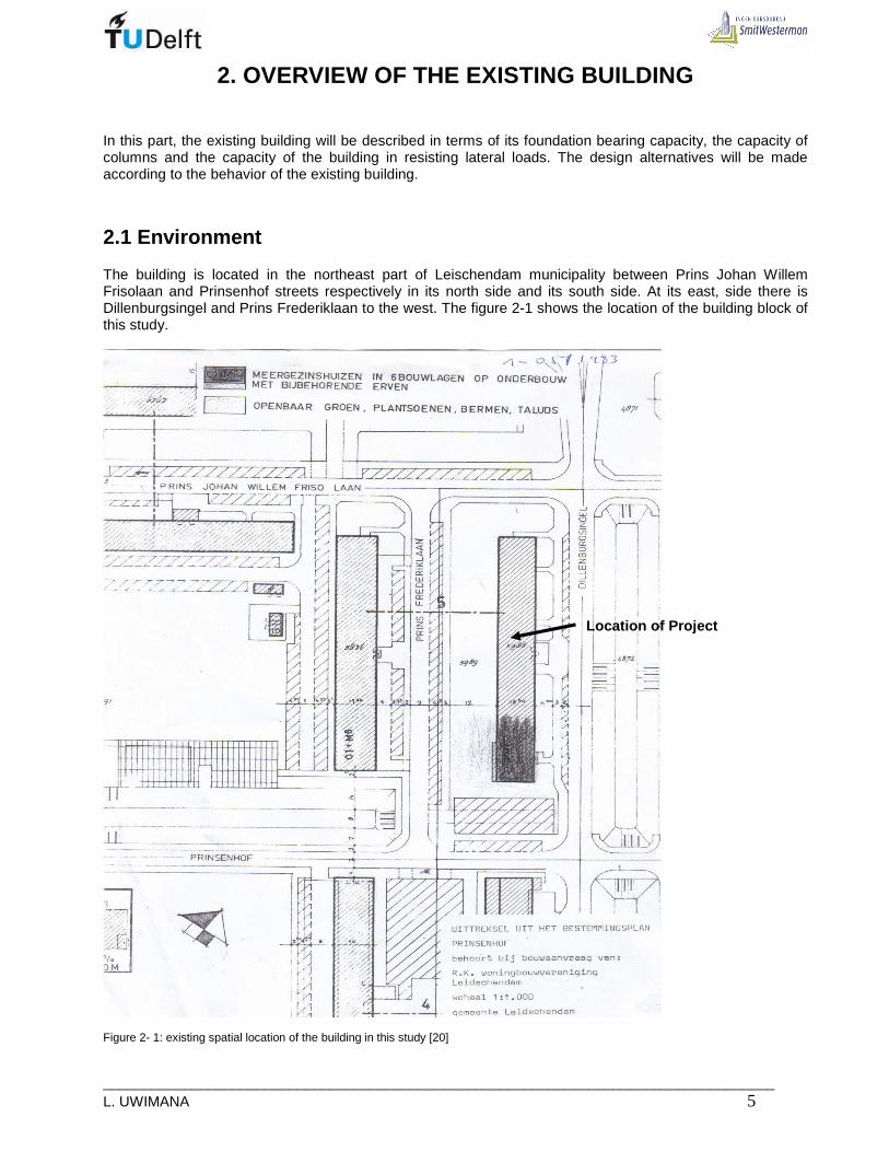
2.1 Environment
The building is located in the northeast part of Leischendam municipality between Prins Johan Willem Frisolaan and Prinsenhof streets respectively in its north side and its south side. At its east, side there is Dillenburgsingel and Prins Frederiklaan to the west. The figure 2-1 shows the location of the building block of this study.
Figure 2- 1: existing spatial location of the building in this study [20]
Location of Project

_____________________________________________________________________________ 6 MSc Thesis
The distance between the edges of the building and Dilenburgsingel is 10m; while the distance to the Prins Frederiklaan is 20m. The piping systems and other public utilities are located at Prins Frederiklaan side-Figure2-2.
Figure 2- 2: Location of pipes [20] The old building was constructed in 1968 according to the building archives from the municipality of Leischendam .In 1983 two low rise annexes were added at one of its ends as they are shown in blue in figure 2-3. The building is one of the similar apartment buildings constructed in that area.
(a) Rough floor plan
(b) Rear façade at Frederiklaan after demolishing southern part ( c) Part of front façade at Dillenburgsingel Figure 2- 3: Existing situation of the building The old building is 6-storey ; at this moment the building is undergoing a complete renewal. On the south side nine more apartment floors will be added.
Prins Johan Willem
Frisolaan
Dillenburgsingel
Frederiklaan
Prinsenhof

___________________________________________________________________________________ L. UWIMANA 7
The old building consists of main load bearing structures stabilized by elevator shafts. The additional 9-stories extend beyond the front facade of the by creating a cantilever of nearly 6 meters. The current building can be divided into three parts according to the figure2-4; the north-west side( see figure2-1), from axis 7 to axis 21. The second part is the south-east; from axis 1 to axis 7. The third part in extreme south-east from axis -1 to axis 1.
(a) General floor plan
(b) Impression of final structure Figure 2- 4: New and Existing situation of the building [25] The northern part This part consists of the existing 6-storey apartment building. It’s getting renovated for both internally and externally. This part is not a part of this study. The southern part This part consists of 6-storey building on which additional 9-floors will be added; in transverse direction it’s limited by axis C to H. This part will be the main focus of this study when conducting a research into the possibility of using light weight material as solution method to provide more stories to the existing building. This project will be used as case study to make an optimal design complying with structural and functional requirements of residential building. The extreme south part. This part will also be at the same level as the southern part;15-storey. It starts at ground level and houses the stair case and elevator shafts. It will not be taken into account during this study.

_____________________________________________________________________________ 8 MSc Thesis
2.2. Soil condition and ground water
Various tests were conducted in order to find the soil properties. Six testing points were set up on site where the building is standing. The cone penetration test (SPT) was done to determine the soil bearing capacity and to know the depth at which the piles will be driven. Figure figure2-5 shows the tested points; D1 to D6.
Figure 2-5 Soil testing location [20] The cone penetration test was conducted mostly up to 22 meters deep, and cone resistance was plotted against the depth. Figure 2-6 shows the plot generated at point D2. For all points, the sufficient capacity was reached at 15m; that is why it was decided to drive all piles up to 15m-figure2-7

___________________________________________________________________________________ L. UWIMANA 9
Figure 2- 6: Cone Resistance at point D2 [20] Figure 2- 7 : Location of Pile point [20] Furthermore, the information about the ground water and soil type is provided. According to the soil profile of the site at different points the ground water table is at 1.5m deep. In 1m deep, there are two layers; fine sand and peat. Going deeper the type of soil is fine sand-figure 2-8.
Figure 2- 8 Ground water table and soil type [20]

_____________________________________________________________________________ 10 MSc Thesis
2.3. Structural members of the existing building
2.3.1. Walls
The existing building is six storeys high. Its structural system is made by concrete frame with in-fill of concrete blocks. These frames are located in all transverse axes (see figure 2-9 and 2-10) to carry the gravity loads as well as lateral loads.
Figure 2- 1: Floor plan of the existing building (1st to 6th floor) [25]

___________________________________________________________________________________ L. UWIMANA 11
Figure 2- 2: Cross- sections of the existing building in axes 1to 7 [25] The masonry in-fill are made of concrete block-work, so called “Muwi”-system. These are large concrete bricks with two holes. The holes in the bricks are filled with concrete and reinforcement bars (see figure2-11)
Figure 2- 3: In-fill Block work in frame l of existing building
_____________________________________________________________________________ 12 MSc Thesis
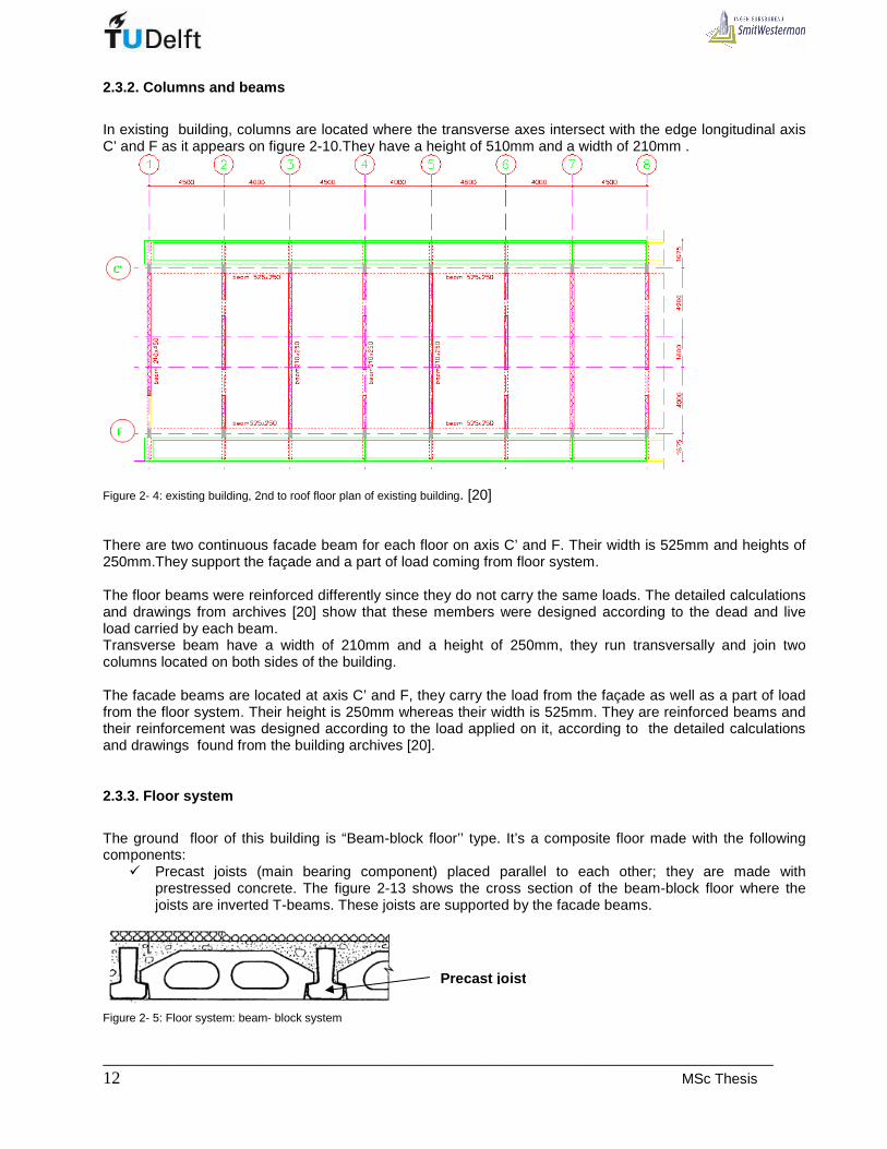
2.3.2. Columns and beams
In existing building, columns are located where the transverse axes intersect with the edge longitudinal axis C’ and F as it appears on figure 2-10.They have a height of 510mm and a width of 210mm .
Figure 2- 4: existing building, 2nd to roof floor plan of existing building. [20] There are two continuous facade beam for each floor on axis C’ and F. Their width is 525mm and heights of 250mm.They support the façade and a part of load coming from floor system. The floor beams were reinforced differently since they do not carry the same loads. The detailed calculations and drawings from archives [20] show that these members were designed according to the dead and live load carried by each beam. Transverse beam have a width of 210mm and a height of 250mm, they run transversally and join two columns located on both sides of the building. The facade beams are located at axis C’ and F, they carry the load from the façade as well as a part of load from the floor system. Their height is 250mm whereas their width is 525mm. They are reinforced beams and their reinforcement was designed according to the load applied on it, according to the detailed calculations and drawings found from the building archives [20].
2.3.3. Floor system
The ground floor of this building is “Beam-block floor’’ type. It’s a composite floor made with the following components:
� Precast joists (main bearing component) placed parallel to each other; they are made with prestressed concrete. The figure 2-13 shows the cross section of the beam-block floor where the joists are inverted T-beams. These joists are supported by the facade beams.
Figure 2- 5: Floor system: beam- block system
Precas t joist
___________________________________________________________________________________ L. UWIMANA 13
� Prefabricated infill blocks, placed between the joists. The blocks are made of light weight concrete.
They are shown between the joists on figure 2-10. � In-situ concrete filling combined with an integral concrete topping.
The floor units are spanning longitudinally and they are supported by the floor beams placed directly to the bearing walls. The floor beams have the cantilever portions which protrude the facade walls in order to support the balconies. Other floors are solid floor made in reinforced concrete; they are designed according to the loads applied on it both permanent and live loads. The applied load allowed calculating the moments, the reaction forces, the shear forces as well as reinforcing steel. The concrete used is K225 and the reinforcement is QRn40.
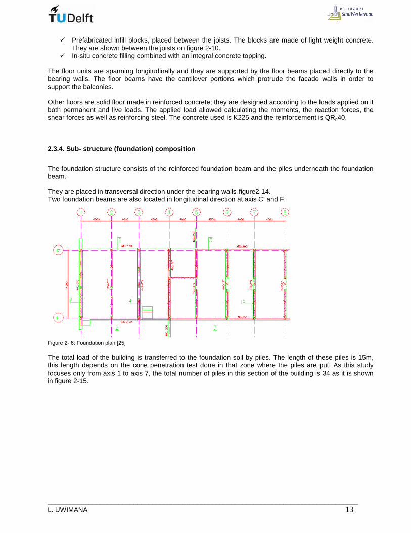
2.3.4. Sub- structure (foundation) composition
The foundation structure consists of the reinforced foundation beam and the piles underneath the foundation beam. They are placed in transversal direction under the bearing walls-figure2-14. Two foundation beams are also located in longitudinal direction at axis C’ and F.
Figure 2- 6: Foundation plan [25] The total load of the building is transferred to the foundation soil by piles. The length of these piles is 15m, this length depends on the cone penetration test done in that zone where the piles are put. As this study focuses only from axis 1 to axis 7, the total number of piles in this section of the building is 34 as it is shown in figure 2-15.

_____________________________________________________________________________ 14 MSc Thesis
Figure 2- 7: Pile plan [25]
2.4 Capacity of structural elements of the old buil ding.
The structural design and detailing for this building was done by “Construction company A. van ECK N.V” in 1967. The results of the detailed design are found in the building archives [20] from the Leidschendam city. The document is titled “348 Galerijwoningen te Leidschendam”. According to the calculation documents, the loads which have been used in designing the structural members are represented in tables2-1a, b, and c. This section will emphasize on capacity of columns, foundation piles and lateral stiffness which can help in stabilizing the new building.
• Load on floors Table2- 1: Loading of the existing building [20] (a) Loading on floors (b): Loading on balconies and corridors
Type of load Load[kg/m^2] Total load [kg/m^2]
Own weight 240
Finishing and isolation
50
Gravel 60
Snow 50
Own weight 240
Finishing and isolation
60
Partition 50
Live load 200
5th floor 550-20 530
4th floor 550-40 510
3rd floor 550-60 490
2nd floor 550-80 470
1st floor 550-100 450
Ground floor
550-120 430
q-total 3830
Roof 400
6th floor 550
Type of load Load[kg/m^2] Total load[kg/m^2]
Own weight 270
Light concrete 180
Finishing andisolation
50
Gravel 60
Snow 50
Own weight 270
Live load 200
5th floor 470-20 450
4th floor 470-40 430
3rd floor 470-60 410
2nd floor 470-80 390
1st floor 470-100 370
q-total 3030
Roof 510
6th floor 470
___________________________________________________________________________________ L. UWIMANA 15
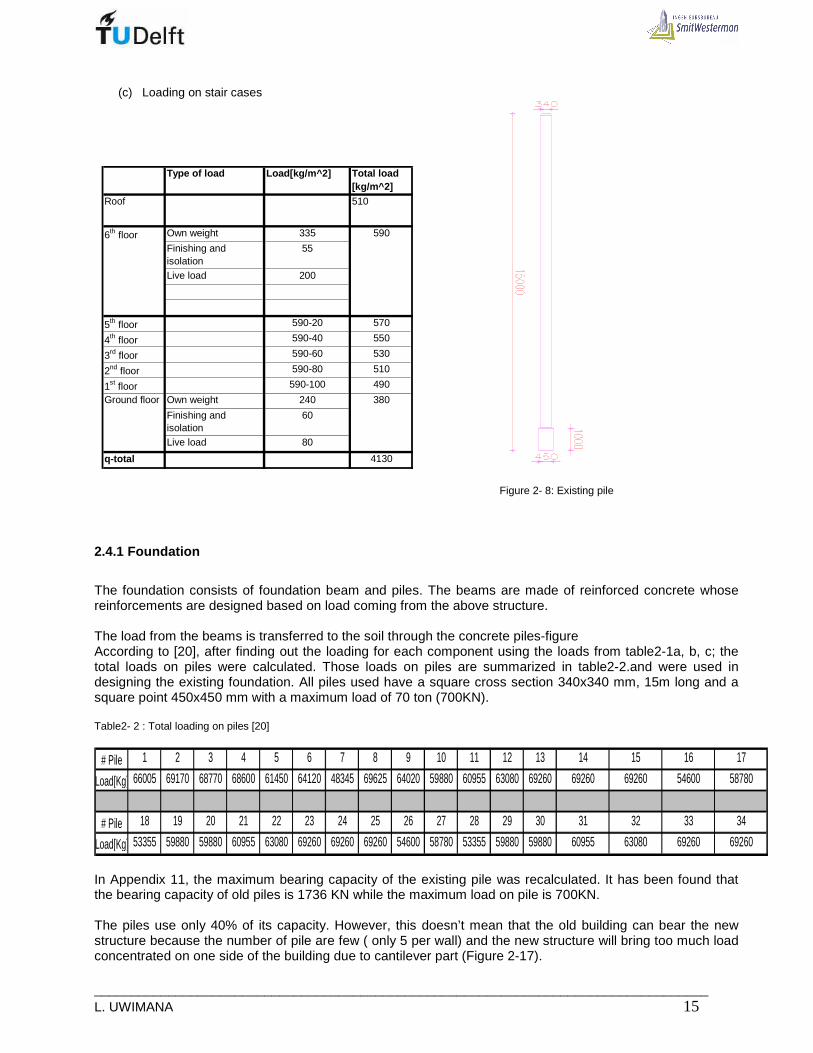
(c) Loading on stair cases
Type of load Load[kg/m^2] Total load [kg/m^2]
Own weight 335
Finishing and isolation
55
Live load 200
5th floor 590-20 570
4th floor 590-40 550
3rd floor 590-60 530
2nd floor 590-80 510
1st floor 590-100 490
Own weight 240
Finishing and isolation
60
Live load 80
q-total 4130
6th floor 590
Ground floor 380
Roof 510
Figure 2- 8: Existing pile
2.4.1 Foundation
The foundation consists of foundation beam and piles. The beams are made of reinforced concrete whose reinforcements are designed based on load coming from the above structure. The load from the beams is transferred to the soil through the concrete piles-figure According to [20], after finding out the loading for each component using the loads from table2-1a, b, c; the total loads on piles were calculated. Those loads on piles are summarized in table2-2.and were used in designing the existing foundation. All piles used have a square cross section 340x340 mm, 15m long and a square point 450x450 mm with a maximum load of 70 ton (700KN). Table2- 2 : Total loading on piles [20]
# Pile 1 2 3 4 5 6 7 8 9 10 11 12 13 14 15 16 17
Load[Kg] 66005 69170 68770 68600 61450 64120 48345 69625 64020 59880 60955 63080 69260 69260 69260 54600 58780
# Pile 18 19 20 21 22 23 24 25 26 27 28 29 30 31 32 33 34
Load[Kg] 53355 59880 59880 60955 63080 69260 69260 69260 54600 58780 53355 59880 59880 60955 63080 69260 69260
In Appendix 11, the maximum bearing capacity of the existing pile was recalculated. It has been found that the bearing capacity of old piles is 1736 KN while the maximum load on pile is 700KN. The piles use only 40% of its capacity. However, this doesn’t mean that the old building can bear the new structure because the number of pile are few ( only 5 per wall) and the new structure will bring too much load concentrated on one side of the building due to cantilever part (Figure 2-17).

_____________________________________________________________________________ 16 MSc Thesis
Figure2- 17: New structure with cantilever part (in actual design)[25]
2.4.2. Columns
The supporting columns are located in front and rear façades; they carry the load from the floor, façade beams and consoles carrying the balconies. The reinforcement for these columns is determined according to the normal forces and moment created by the loading system. The reinforcement area increases downward as function of the normal forces. The detailed calculations and drawings are also found in the building archives stated before. [20] The capacity of frame will be basically depend on columns strength; for this reason only columns are checked since additional load to the structure can be conducted through the existing column.
• Applied axial forces from gravity load
The gravity loads in the columns come from the tributary areas; these loads were collected from design archives [20] and are shown in table 2-3. A large amount of vertical load is taken by the masonry in-fill. Axial forces in the columns and beams resulting from the horizontal loading should be estimated by simple static analysis of the analogous braced frame considering each infill as a diagonal strut. These two kind of axial forces are added to form the design force for each column.

___________________________________________________________________________________ L. UWIMANA 17
Table2- 3 Load, moments and reinforcement of existing columns [20] Nmax in Kg Mmax in Kgm
Nmax Mmax R-bar Nmax Mmax R-bar Nmax Mmax R-bar Nmax Mmax R-bar Nmax Mmax R-bar Nmax Mmax R-bar Nmax Mmax R-bar
Under 6th floor Col.C' 17060 1347 6ф10 19055 1048 6ф10 25580 1017 6ф10 25580 1017 6ф10 24030 1049 6ф10 25580 1017 6ф10 16510 1147 6ф10
Col. F 17060 1347 6ф10 19055 1048 6ф10 27295 1017 6ф10 25580 1017 6ф10 24030 1049 6ф10 25580 1017 6ф10 18220 1147 6ф10
Under 5th floor Col.C' 17060 1347 6ф10 19055 1048 6ф10 25580 1017 6ф10 25580 1017 6ф10 24030 1049 6ф10 25580 1017 6ф10 16510 1147 6ф10
Col. F 17060 1347 6ф10 19055 1048 6ф10 27295 1017 6ф10 25580 1017 6ф10 24030 1049 6ф10 25580 1017 6ф10 18220 1147 6ф10
Under 4th floor Col.C' 22600 1136 6ф10 25580 1017 6ф10 25580 1017 6ф10 25580 1017 6ф10 24030 1049 6ф10 25580 1017 6ф10 22150 1475 6ф12
Col. F 27215 1556 6ф12 30180 1449 6ф14 27295 1017 6ф10 25580 1017 6ф10 24030 1049 6ф10 25580 1017 6ф10 24435 1475 6ф12
Under 3rd floor Col.C' 28320 1346 6ф12 32090 1307 6ф12 32090 1307 6ф12 32090 1307 6ф12 30440 1348 6ф12 32090 1307 6ф12 27810 1806 6ф14
Col. F 34460 1766 6ф16 38230 1629 6ф18 34375 1307 6ф12 32090 1307 6ф12 30440 1348 6ф12 32090 1307 6ф12 25525 1806 6ф14
Under 2nd floor Col.C' 34050 1555 6ф14 38645 1598 6ф16 38645 1598 6ф16 38645 1598 6ф16 36650 1647 6ф16 38645 1598 6ф16 33465 2135 6ф18
Col. F 41725 1975 6ф20 46320 1960 6ф20 41500 1598 6ф18 38645 1598 6ф16 36650 1647 6ф16 38645 1598 6ф16 36320 2135 6ф18
Load Under 1st floor Col.C' 39790 1765 6ф18 45170 1925 6ф20 45170 1925 6ф20 45170 1925 6ф20 42820 2033 6ф20 45170 1925 6ф20 39020 2465 6ф22
Col. F 48990 2185 6ф22 54370 2250 6ф24 48600 1925 6ф22 45170 1925 6ф20 42820 2033 6ф20 45170 1925 6ф20 42450 2465 6ф22
Total Col.C' 8496 7943 7881 7881 8175 7881 10175
Moment Col. F 10176 9384 7881 7881 8175 7881 10175
Total moment 18672 17327 15762 15762 16350 15762 20350
Floor Member
Vertical load in Kg, moment in Kgm and reinforcemen t per column
Wall 1 Wall 2 Wall 3 Wall 4 Wall 5 Wall 6 Wall 7
• Applied force due to horizontal load As the frame with in-fill masonry behaves as braced frame, the axial load in columns due to horizontal load can be calculated as follow:
12
Hc
MF
b= ± ; 21
.2H wM q H= ; , . 1.28,6 28,6 /w w repq q L KN m= ⇒ = ; as there are 7
frames, one takes 28,6 / 7 4 /KN m=
2 21 1. 4.19,6 768
2 2H wM q H KNm= ⇒ = , therefore768
1541
102
cF KN= ± = ±
Where Fc : axial force as a result of horizontal load MH: Moment due to horizontal load b and L: the width and the length of building
H : height of building ,w repq : Representative wind pressure
wq : wind load

_____________________________________________________________________________ 18 MSc Thesis
Table2- 4” Axial load due to lateral moment and moment from vertical load
Lateral axis Total moment Width Equivalentaxial load
[ KNm ] [ m ] [ KN ]1 955 10 1912 941 10 1883 926 10 1854 926 10 1855 932 10 1866 926 10 1857 972 10 194
768768
[ KNm ]187173158
768768768768
204 768
due to vertical loadTotal moment Moment due to
horizontal load
158164158
[ KNm ]
• Axial load capacity of columns In a reinforced concrete column, both longitudinal steel and concrete assist in carrying the load. The links (stirrups) prevent the longitudinal bars from buckling. According to Euro Code 2 [23], the ultimate load capacity of column is given by the following expression
cd c st ydN f A A fα= +
0,85α = , 22013,3 /
1,5 1,5ck
cd
ff N mm= ⇒ = and 2400
348 /1,15 1,15
ykyd
ff N mm= ⇒ =
Where N is the ultimate load capacity Fcu: ultimate strength of concrete (K300 or 20N/mm2) Ac: area of concrete (A tot – Ast) Ast: Total area of longitudinal reinforcement fy: Yield strength of steel( Q40 or 400N/mm2) The capacity for all columns on ground level can be calculated and compared to the applied load. The applied load is found in table 2-3 under first floor. The calculations are summarised in table 2-4: Table2- 5: Calculation of the capacity of the existing columns
Longitudinal Transversal f cd Ac Asc fyd Ultimate % of used
Due to M H Total applied
Axis Axis N/mm 2 mm 2 mm 2 N/mm2 capacity[KN] load [KN] KN load[KN] capacityC' 1 13,3 107100 1526 348 1741,8 397,9 191,0 588,9 34
2 13,3 107100 1884 348 1866,4 451,7 188,0 639,7 343 13,3 107100 1884 348 1866,4 451,7 185,0 636,7 344 13,3 107100 1884 348 1866,4 451,7 185,0 636,7 345 13,3 107100 1884 348 1866,4 428,2 186,0 614,2 336 13,3 107100 1884 348 1866,4 451,7 185,0 636,7 347 13,3 107100 2280 348 2004,2 390,2 194,0 584,2 29
F 1 13,3 107100 2280 348 2004,2 489,9 191,0 680,9 342 13,3 107100 2713 348 2154,9 543,7 188,0 731,7 343 13,3 107100 2280 348 2004,2 486,0 185,0 671,0 334 13,3 107100 1884 348 1866,4 451,7 185,0 636,7 345 13,3 107100 1884 348 1866,4 428,2 186,0 614,2 336 13,3 107100 1884 348 1866,4 451,7 185,0 636,7 347 13,3 107100 2280 348 2004,2 424,5 194,0 618,5 31
Applied load
According to the results, most of the columns use less than 40% of their capacity. The capacity left can take moderate loads but not as much as 9 floors.

___________________________________________________________________________________ L. UWIMANA 19
2.4.3 Stability of the existing building
The existing building consists of the reinforced concrete frames with in-fills of concrete block-work. In addition to functioning as partitions, exterior walls, the in-fills may also serve structurally to brace the frame against horizontal loading. The frame is designed for gravity load only and, the in-fills are presumed to contribute sufficiently to the lateral strength of the structure for it to withstand the horizontal loading.
2.4.3.1 Behaviour of in-filled frames
The use of a masonry in-fill to brace a frame combines some of the desirable structural characteristics of each while overcoming some of their deficiencies. The high in-plane rigidity of the masonry wall significantly stiffens the otherwise relatively flexible frame, while the ductile frame contains the brittle masonry, after cracking, up to load and displacements much larger than it could achieve without the frame. The result is, therefore, a relatively stiff and tough bracing system. The wall braces the frame partly by its in-plane shear resistance and partly by its behaviour as a diagonal bracing strut in the frame. Figure 2-18 illustrate these modes of behaviour. [6]
(a) Interactive behaviour of frame and infill (b). Analogous braced frame Figure 2- 18: Frame and infill behaviour [6] When the frame is subjected to horizontal loading, it deforms with double curvature bending of the columns and girders. The translation of the upper part of the column in each story and the shortening of the leading diagonal of the frame causes the column to lean against the wall as well as to compress the wall against its diagonal. It is roughly analogous to a diagonally braced frame (Fig.2-18 b). Three potential modes of failure of the wall arise as a result of its interaction with the frame, and these are illustrated in Fig.2-19. The first is the shear failure stepping down through the joints of the masonry, and precipitated by the horizontal shear stresses in the bed joints. The second is the a diagonal cracking of the wall through the masonry along a line, or lines, parallel to the leading diagonal, and caused by tensile stresses perpendicular to the leading diagonal. In the third mode of failure, a corner of the infill at one of the end of the diagonal strut may be crushed against the frame due to the high compressive stresses in the corner.

_____________________________________________________________________________ 20 MSc Thesis
Figure 2-19 : Mode of infill and frame failure [6] 2.4.3.2 Checking the capacity of the in-fill Two modes of infill failure may cause collapse of the structure. The first is shear failure stepping down diagonally through the bed joint of the masonry and the second is by spalling and crushing of the masonry in the corners of the infill. The lesser of the two strengths should be taken as the critical value Shear failure: The shear failure of the structure based on the shear failure of the infill should be estimated from:
( ).
1,43 0,8 / 0,2bs
s
f L tQ
h Lµ=
− −
In which bsf :allowable values of the bond shear stress
µ : Coefficient of internal friction.
L : Length of in-fill t : Thickness of in-fill h : Height of each floor Compressive failure: If the infill is bounded by a reinforced concrete frame the shear strength relating to a
compressive failure of the infill should be estimated from 2 342 cosc mQ f Ihtθ=
Where: mf is allowable compressive stress in in-fill
θ is inclination of equivalent diagonal
From Appendix 10, 221sQ KN= and 2435cQ KN= .
The infill is just adequate to carry the external shear on the basis of the shear failure criterion (strength =221KN compared with the shear due to applied load of 71,4KN) and more than adequate on the basis of compressive failure criterion (strength = 2435KN).

___________________________________________________________________________________ L. UWIMANA 21
2.4.3.3 Checking the deflection
A conservative estimate of the horizontal deflection of an in-filled frame would be given by the calculated deflection of the equivalent pin jointed braced frame as summing each infill to be replaced by a diagonal strut with a cross sectional area equal to the product of one-tenth of its diagonal length and its thickness [6] . There are two kinds of deflection; namely flexural deflection as well as shear deflection. (i). Flexural component This component depends on bending stiffness of frame. At each floor level the deflection is calculated and finally added up. The procedure is shown in Appendix 10 and any component prior to calculation are filled in a table for calculation. After calculation the deflection at each floor, the final deflection due to flexure is the sum of floor deflection:
; ;f tot f iδ δ=∑
It has been obtained that the final horizontal drift due to flexure is ; 0,16f tot mmδ =
(ii). Shear component The shear due to horizontal force participates in increasing the deflection. Its magnitude depends up on physical behaviour of in-fill and a little participation of frame members. The bracing member is obtained by
making an equivalent diagonal strut and its equivalent cross section is given by this formula: 1
.10d dA L t=
Where dL : length of equivalent diagonal
dA Cross section of equivalent diagonal
t Thickness of in-fill As the infill with frame behave as braced bent, the deflection for each transverse frame is calculated as follows
3
; 2
gi ds i
g d g
LQ L
E L A Aδ
= +
[6]
Where: ;s iδ : shear deflection at each floor level
gL : length of beam above in-fill
iQ : shear force due to lateral load at each floor level
E : Modulus of elasticity on in-fill The total deflection due to shear is the summation of deflection at every floor level
; ;s tot s iδ δ=∑ , From Appendix 10, it has been obtained that ; 4,6s tot mmδ = The total drift is the summation of both flexural and shear drifts:
; ; 0,16 4,6 4,8total f tot s tot mmδ δ δ= + ⇒ + =
Normally as the building height is 19600mm, the allowable horizontal deflection should be
max
1960039 4,8
500 500
Hmm mmδ = = = >> ; the structure is more stable.

_____________________________________________________________________________ 22 MSc Thesis
2.5 Conclusion on existing building
The old building is made of concrete frame braced by block-work in-fill. This in-fill contributes in carrying floor loads as well as lateral loads. This contribution makes the frame columns to carry fewer loads compared to their load capacity. The new structure is 9-storey high and it cannot rest on existing building, in addition to that the new structure is placed eccentrically( cantilever) with respect to the existing building, this effect bring too much loads on one side of the existing building whose frame cannot tolerate such load. From the following figure (Figure2-20) some conclusions can be drawn;
Figure 2-110 : Service load in new and existing building for axis 5 By taking the axis 5, the total load of the existing building is 3226KN distributed over 5 piles. The existing foundation pile capacity was estimated to 1736KN, as the maximum load applied to each pile is nearly 700KN (70 tons); 60% of the capacity is not used. However, for the same axis 5, the load from the new structure with service load is 7470 KN. Therefore, the total load that would go to the same foundation would be 10696 KN, consequently, 5 piles cannot handle this load and hence the new structure should have its own foundation since providing more piles to the existing foundation is practically impossible. The only thing the existing building can do is to help the new one in restraining the lateral loads since its frames with their in-fills are very stiff in their planes. It can be done by connecting rather than supporting the new structure to the existing one in lateral direction.

___________________________________________________________________________________ L. UWIMANA 23
3. REFERENCE PROJECTS
In This section, some projects having similar properties to the case study of this thesis will be described in order to adopt structural concept that can be compatible with the case study of this thesis.
3.1 Actual design of Smitwesterrman
3.1.1 General description
In this section, the current design made by the design office of SmitWesterman will be described so that one can see the difference between this design and the final concept that will be obtained at the end of the thesis. The actual construction is a residential facility of 15 floor levels above the ground level with a total height of 47m. It is located in Leidschendam at Dillenburgsingel Street. This project exactly the case study of this thesis. The designers of this project wanted to put nine more floors to the existing six floor building, but they skipped the concept by designing another similar structure by starting from the foundation. They thought that its probably possible to put nine more floors on existing building that is why they forwarded the projected(case ) to the university so that anyone interested can make possible designs of adding more story to the existing building. In this project, structure is mainly made of concrete and the whole building seems to be unique since the existing building was completely demolished. This construction method differs from the objectives of this thesis whereby the additional structures can be made without bringing down the existing building. Various data of this project such as drawing will be consulted in the work of this thesis because the final products should be functionary the same but structurally different. Previously, there was an old building of 6 floor levels constructed from axes 1 up to 21 ( Figure 3-1b ) with 10m wide ( without considering balconies on both sides of the building), thereafter, it was decided to increase the number of floors up to 15 and increasing the width of the building to 20m from 7th floor and above. The raised part of the building has a length of 37, 1 m in which 25,5 m coinciding with the old building ( from axis 1 to 7) - Figure 3-1b and an other part of 8,5 m which is added next to the existing building to accommodate the elevators stair cases and additional rooms. In summary the 15 –storey constructed is 37,1m long and 14m wide (from ground to the 6th floor ) and 20 m from 7th to 15th floor with a total height of 47,2m.
a. Pictures of the final structure

_____________________________________________________________________________ 24 MSc Thesis
b. Overview of the old and new building in plan Figure 3-1: Overview of the new building as it is integrated with the old building [25] To construct this building, the old building from axis 1 to 7 was simply demolished so that the construction starts by making a new foundation and constructing walls capable to withstand the load of the new structure. Figure 3-2 shows the old building after demolishing where the multistory building will be constructed.
Figure 3-2: The remaining structure from axes 7 to 21 after demolishing from 1 to 7
3.1.2 Functional concept
The new structures consist of two specific parts; the first 6 floors which are in line with the old building and 9 floors with lateral cantilevers of 6m beyond the existing building. From axis 1 to 7 of the first 6 floors, the building consists of 3 apartments arranged similarly to the existing building and can be accessed through the staircase or levitator (from axis -1 to 0) and balconies on front facade. The part between -1 and 0 accommodates elevators, staircase and one apartment. (Figures 3-3 and 3-4).
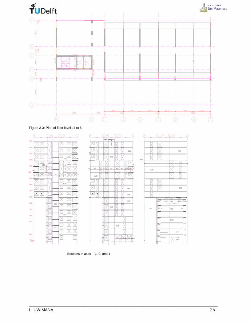
___________________________________________________________________________________ L. UWIMANA 25
Figure 3-3: Plan of floor levels 1 to 6
Sections in axes -1, 0, and 1

_____________________________________________________________________________ 26 MSc Thesis
Sections in axes 3, 5, and 7 Figure 3-4: Cross section of the new building [25] From 7th to 15th floor, the new building has 5 apartments and their access corridors are inside the building. For floor levels 7,8,9,13,14 and 15, this corridor is between F and G ( Figure3-5a) , whilst it is between axes D and E for floor levels 10,11 and 12(Figure 3-5b)
(a) Plan of floor level 7,8,9,13,14,15
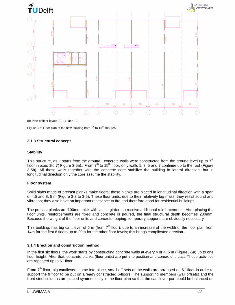
___________________________________________________________________________________ L. UWIMANA 27
(b) Plan of floor levels 10, 11, and 12 Figure 3-5: Floor plan of the new building from 7th to 15th floor [25]
3.1.3 Structural concept
Stability This structure, as it starts from the ground, concrete walls were constructed from the ground level up to 7th floor in axes 1to 7( Figure 3-5a).. From 7th to 15th floor, only walls 1, 3, 5 and 7 continue up to the roof (Figure 3-5b). All these walls together with the concrete core stabilize the building in lateral direction, but in longitudinal direction only the core assume the stability. Floor system Solid slabs made of precast planks make floors; these planks are placed in longitudinal direction with a span of 4,5 and 8, 5 m (Figure 3-3 to 3-5). These floor units, due to their relatively big mass, they resist sound and vibration; they also have an important resistance to fire and therefore good for residential buildings. The precast planks are 100mm thick with lattice girders to receive additional reinforcements. After placing the floor units, reinforcements are fixed and concrete is poured, the final structural depth becomes 280mm. Because the weight of the floor units and concrete topping, temporary supports are obviously necessary. This building, has big cantilever of 6 m (from 7th floor), due to an increase of the width of the floor plan from 14m for the first 6 floors up to 20m for the other floor levels; this brings complicated erection.
3.1.4 Erection and construction method
In the first six floors, the work starts by constructing concrete walls at every 4 or 4, 5 m (Figure3-5a) up to one floor height. After that, concrete planks (floor units) are put into position and concrete is cast. These activities are repeated up to 6th floor. From 7th floor, big cantilevers come into place, small off-sets of the walls are arranged on 6th floor in order to support the 9 floor to be put on already constructed 6-floors. The supporting members (wall offsets) and the front steel columns are placed symmetrically in the floor plan so that the cantilever part could be balanced on

_____________________________________________________________________________ 28 MSc Thesis
both sides of the building. A table -like structure is therefore created on 7th floor, then 9-floors in form of box are put on that table. The 9-floor box is made of prefabricated concrete walls of 250mm thick and floor system, which consists of hollow core slabs of 260mm thick. (Figure 3-6)
(a) 7th floor (b) Floor erection progress (c) End of erection Figure 3-6: Erection of 7th floor [25]
3.1.5 Useful point from this project that can be us ed in the thesis
The final product of this thesis should more or less be the same as the product of this project in terms of functionality even though the structural systems may be different. The system used in this project could be adopted in the thesis where the whole structure starts from the ground; namely the section between axes -1 and 0. The part between axes 0 and 7, an other system must be obtained.
3.2 Kennedy tower in Eindhoven

___________________________________________________________________________________ L. UWIMANA 29
Figure3-8: Picture of Kennedy tower in Eindhoven [32] and [33] Location: Eindhoven, Netherlands Principal Ontwikkelingscombinatie Eindhoven
Start 2001, January
Commissioning 2002, December
Architect: Van Aken Architecten
Designer Adviesburo Tielemans
Contractor Geveke/CFE, Rotterdam Steel construction: Victor Buyck, Eeklo Completion 1999 Tonnage 800 ton Height 83m(21 floors) Total area 30,000 m². Ground surface 21,6m x 36m
3.2.1 General description and Functional concept
The Kennedy Tower in the heart of Eindhoven. With its central location, highly flexible and customizable floor plans and modern, transparent latest offers over 80 m tall office tower overlooking long-term returns for owners and users. The desire for an unobstructed view and a view of the twenty-story office brought the design team of contractors, architects and engineers at a steel main structure of columns and struts. The Kennedy Tower is a landmark in the area. With its glass walls, the location of the tower in a "double-skin facade" model makes it a landmark in the area, ensuring the transparency on the one hand reflects the technological, innovative appearance, and also a neutral transitional form between the very different architectural buildings of the Kennedy Business Center. The disposition of the tower relative to the substructure is challenging and takes a huge overhang of the tension. The choice of a steel construction of the tower makes this possible and has the added advantage that the problem can disappear from a sealed concrete core, the building is really transparent and provides great freedom in designing the office floors. [34] The Kennedy Tower is designed as a technological and programmatic quality and flexible office complex for lease. The total includes 30,000 m² of gross floor area. The atrium is the central building which housed a few auxiliary functions for the various businesses, including catering facilities, a business lobby and lounge area, child care, and corporate fitness facilities.
3.2.2 Structural concept and construction method
For the sake of transparency of the support structure is 82.8 meters high tower columns and braces. The construction was very consciously integrated into the design by selecting a Y-shaped structure, with each diagonal line of the Y still provides the stability of three stories (Figure 3-9).

_____________________________________________________________________________ 30 MSc Thesis
Figure3-9: Kennedy tower during construction [35]
Circular hollow sections which are flame retardant were used to form frame of this building. Stabilizing the frame using bracing instead of conventional concrete core resulted in structural design that is more transparent and more flexible. The composite slabs on floors were used because they facilitate various office formats (figure3-10). These floor are also lighter compared to other kind of floors and can be constructed quickly.
Figure 3-10: Floor Construction
3.2.3 Useful point from this project that can be us ed in the thesis
In this project, steel structures were used and the structure has a huge cantilever. These aspects of this project are similar to the project of this thesis; therefore, the stability system, the support of cantilevers can be adopted and used in the work of this thesis.

___________________________________________________________________________________ L. UWIMANA 31
3.3 Hogeschool voor muziek en dans Rotterdam (HMDR)
Figure3-10: Artistic impression of HMDR [36] Location: Kruisplein, Rotterdam Architect: Jan Hoogstad, Rotterdam Designer Aronsohn Raadgevende Ingenieurs, Rotterdam Contractor Geveke/CFE, Rotterdam Steel construction: Victor Buyck, Eeklo Start Commission Height 48 m(9 floors) Total area 10,000 m². Ground surface (Min)13,5m x 75m and (Max) 20 m x 75m
3.3.1 General description
This building is located in Rotterdam next to the theater “De Doelen”. It is a conservatorium for education of musicians and dancers. It is characterized by its huge overhang which is 5-stories high. It has much column free area required for dance halls and classes. All spaces are made sound proof due to musical requirements
3.3.2 Functional concept
This building has many different rooms depending on different users. The building is also complex due to its integration with theatre “De Doelen”. HMDR is constructed in Steel , wheras “De Doelen” is in concrete. On ground level the building is divided into two sections; the entrance for the HMDR and entrance for “De Doelen”. In both sections, there are central core , elevators and staircases, Large escalators at the back side of the building provides the users of HMDR to a public entrance at the fifth floor level. The HMDR uses elevators for lifting heavy instruments (Figure 3-11)
Figure 3-11: Functional plan of the second floor [37]

_____________________________________________________________________________ 32 MSc Thesis
The Building has these rooms:
• 1 recording room • 1 music hall • 1 theatre studio • 10 dance studios • 40 music rooms • 20 study rooms
All these rooms have different specifications and differ in height and area. Some rooms require column- free areas. The type of room influences the functional as well as structural concept of the building.
3.3.3 Structural concept
To stabilize this structure was challenging due to slender cores in lateral direction. The stability was obtained by using table-like structure composed by the 5th floor and 2 shear walls in each building( De Doelen and HMDR)( Figure 3-12)18],[37] Horizontal loads are restrained by the concrete cores and table structure depending on stiffness of the cores and transverse stiffness of table structure.
Figure3-12: Table structure in each building [18],[37] Because table structure is very stiff in lateral direction, core seems to be supported on 5th floor; this results in reduced shear force and bending moments in foundation(Figure 3-13).
Figure3-13: Moment and shear force diagram when core is connected to 5th floor [37] Floor system is made by prefabricated planks , because a big mass is needed to avoid noise and vibration during dancing or singing .The width of the first 4 floors is 13m and 20m for above floors. The planks are laid in longitudinal direction.
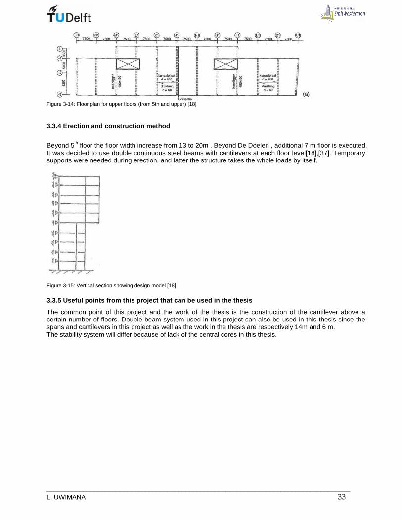
___________________________________________________________________________________ L. UWIMANA 33
Figure 3-14: Floor plan for upper floors (from 5th and upper) [18]
3.3.4 Erection and construction method
Beyond 5th floor the floor width increase from 13 to 20m . Beyond De Doelen , additional 7 m floor is executed. It was decided to use double continuous steel beams with cantilevers at each floor level[18],[37]. Temporary supports were needed during erection, and latter the structure takes the whole loads by itself.
Figure 3-15: Vertical section showing design model [18]
3.3.5 Useful points from this project that can be u sed in the thesis
The common point of this project and the work of the thesis is the construction of the cantilever above a certain number of floors. Double beam system used in this project can also be used in this thesis since the spans and cantilevers in this project as well as the work in the thesis are respectively 14m and 6 m. The stability system will differ because of lack of the central cores in this thesis.

_____________________________________________________________________________ 34 MSc Thesis
3.4 Red Apple Rotterdam
Figure 3-16: Red apple pictures [38] Location: Rotterdam, Netherlands Principal Woning Stichting Rotterdam Start Commissioning 2009 Architect: KCAP Architects&Planners
Design Studio Jan des Bouvrie, Naarden
Dirk Jan Peters
Designer Contractor Steel construction: Tonnage Height 124 m(21 floors) Total area 35,000 m². Ground surface
3.4.1 General description and Functional concept
In Rotterdam, June 5, 2009 - KCAP Architects&Planners completes residential high rise development The Red Apple in Rotterdam; 124 metres high The Red Apple rises skyward at the head of Wijnhaven Island, located between Rotterdam's city centre and the river Maas. The Red Apple is a highly varied architectural development with 231 apartments, offices, retail and restaurants on a total gross floor area of 35.000 m2. The Wijnhaven Island occupies a strategic spot within the city. It is being redeveloped using a dynamic transformation model, which provides development guidelines that ensure a balance between new and existing construction as well as the preservation of fine views and sufficient incidence of daylight throughout the area. “By applying this model, its redevelopment substantially increases the area's capacity and improves the residential and environmental quality while preserving important qualities of the existing situation” states architect Han van den Born (KCAP). The Red Apple complex is situated on a visually prominent location: at the tip of the Wijnhaven Island, with water on three sides and views across the river and the “Old Harbor'”. The converging lines of Wijnhaven

___________________________________________________________________________________ L. UWIMANA 35
Island meet at The Red Apple, outlining a five-sided volume, part of which cantilevers beyond the substructure. In this block building, apartments of various sizes are grouped around a central atrium. The southwest corner of the site is occupied by a slender apartment tower with a spacious glazed lobby as ground-floor entrance and live/work loft spaces on top. The levels 8 through to 40 contain apartments of various sizes. All apartments of the two volumes are diagonally oriented and offer a maximum of transparency via floor-to-ceiling glass and provide extraordinary views.
3.4.3 Structural concept
The interesting part is the low riser building with huge cantilever; it looks like a box placed on top of supports. This big cantilever is achieved by using 2-stories truss girder in which its vertical members are columns of the top structure and the bottom and top chords are floor beam (Figure3-17) [38]
Figure 3-17: Supporting structure [39]
The building is stabilized by braced steel frames because concrete core is not possible since where it should be , there is an glass atrium which takes 3-stories.
3.4.4 Erection and construction method
Lower building is erected first since it contains columns which support the top part of the building. Temporary supports are necessary during construction so that the young structure gets stable as soon as steel elements are erected (Figure 3-18).
3-18: Red Apple during construction [39] 3.4.5 Useful points from this project that can be u sed in the thesis The important section of this project with respect to the work of this thesis is the low rise building in which a bloc of 9-floors is put on top of the structure previously constructed. But both structures share the supporting columns; this is not the case in the work of this thesis. The only thing, which can be leant from this project, is stability system and handling the gravity loads.

_____________________________________________________________________________ 36 MSc Thesis
3.5 Conclusion
In SmithWesterrman, design was one of the options to raise the height of Dillenburgsingle building. In contrast to the objectives of this thesis, their structure was achieved by demolishing the old building and the structure is made mainly by concrete. However, the construction method used between axes -1 and 0 can be used in this project. All the other remaining projects are made in steel and all have long cantilevers. The way these structures are made can help in determining the structural system required for Dillenburgsingle case study. The difference between the structural system of the above-mentioned projects and the case in this thesis is the presence of existing building which should stay untouched during construction of additional floors.

___________________________________________________________________________________ L. UWIMANA 37
4. STRUCTURAL SYSTEM TO BE USED IN THE CASE STUDY
4.1 The design
To be able to design a structural solution for the given problem, it was necessary to get an insight in the vision of the principal as well as that of the architects. These two visions have been used to create the design in which the shape is the most essential element. The shape has been designed to emphasize the ideas of the architect.
4.2 Vision
The assignment given to architect was to create a design that is more attractive from both architectural and engineering point of views. The new design should provide more homes without putting down the already existing building and without using the existing terrain to erect a more extended building. The new design must be congruent to the existing built environment. The point of great attention in this design is the location of the supporting columns in such a way that they don’t affect the existing building
• The structural design should also meet aesthetical, functional, and technical requirements. • The loads from the new building should be conveyed to the ground by the columns erected on sides
of the existing building. • The new alternative designs should have more relevant advantages in comparison to the current
design whereby the existing building is demolished in order to make a new beginning
4.3 Boundary conditions
• Space to the main street (Dillenburgsingel) is small, no columns should be put there; cantilever is necessary to get required spaces.
• The new building should be carefully connected to the existing without transferring vertical, load to the existing building.
• On the rear façade of the building there’s a low building and piping system; so, the position of columns should not be shifted.
The deformations of the new building should be limited since any excess deformation will put load on existing building.
4.4 Interaction between floor framing and the bui lding function
In current situation, the structure was implemented by using load bearing concrete walls as major supporting and bracing members, these walls are separated by a distance of 8.5m and located on odd axes- Figure 4-1. (see also 3.1) If the even axes could be considered, there would be a possibility to increase the number of supporting columns since the underneath structure will not contribute in carrying the load of the added structure. The even axes correspond to the location of partition walls and can cover the structural members. The advantage of introducing many frames is to reduce the size of structural members and to spread the vertical loads through many points to avoid large foundation load near the existing foundations. Finally, the inter-distance between two steel frames will be either 4,5m or 4,0m (Figure4-1).

_____________________________________________________________________________ 38 MSc Thesis
a. Floor: 10, 11, and 12
b. Floors: 7, 8, 9, 13, 14 and 15 c.
(c). Floor plan from 7th up 15th floor
Figure 4- 1: Furnished floor plans showing the function and division of spaces
dagm.884
dagm.900
dagm.730
dagm.910
dagm.910
dagm.910
dagm.910
dagm.910
dagm.910
dagm.884
dagm.910
dagm.910
dagm.910
dagm.910dagm.910
dagm.900
dagm.730
dagm.910
dagm.910
dagm.884
dagm.900
dagm.730
dagm.910
dagm.910
dagm.910
dagm.910
dagm.910
dagm.910
dagm.884
dagm.884
dagm.730
dagm.910
dagm.910
dagm.910
dagm.910dagm.910
dagm.910
dagm.900
dagm.910
dagm.884
dagm.730
dagm.910
dagm.910
dagm.910
dagm.910dagm.910dagm.910
dagm.900
dagm.910
dagm.1000
dagm.884
dagm.730
dagm.900
dagm.910
dagm.910
dagm.910
dagm.910
dagm.910
dagm.910
dagm.910
dagm.984
dagm.884
dagm.900
dagm.730
dagm.910
dagm.910
dagm.910
dagm.910
dagm.910dagm.910
dagm.884dagm.884
dagm.730
dagm.900
dagm.910
dagm.910dagm.910 dagm.910
dagm.910
dagm.910
dagm.910
dagm.984
dagm.884
dagm.900
dagm.730
dagm.910
dagm.910
dagm.910
dagm.910
dagm.910
dagm.910
dagm.884
dagm.910
dagm.910
dagm.910
dagm.910dagm.910
dagm.900
dagm.730
dagm.910
dagm.910
dagm.1000
dagm.884
dagm.730
dagm.910
dagm.910
dagm.910
dagm.910dagm.910dagm.910
dagm.910
dagm.900
dagm.884
dagm.730
dagm.910
dagm.910 dagm.910
dagm.910dagm.910
dagm.910
dagm.910
dagm.900

___________________________________________________________________________________ L. UWIMANA 39
4.5 The design parameters (Program of requirements)
To be able to design a structural solution for the given project, it was necessary to get an insight in a number of requirements:
• Structural demand or technical requirement: The new structure will stand on top of the existing without resting on it. The new structure has a cantilever part extending the existing building. The new structure should be as light as possible to reduce the weight on foundation so that no further stress to the existing foundation structure. It must resist the wind load and having a very limited deflection in order to not hinder the existing building.
• Aesthetic requirement: The set of the new and existing building should be aesthetically pleasing. There should be harmony between the new and the existing façade so that they can look like one structure.
• Functional requirements: The new and existing buildings are apartment facilities. They must always keep people comfortable in terms sound and heating requirements.
• Economy: the new structure should be executed at affordable price. All of these requirements are presented in table of program of requirements. The requirements can be divided in Aesthetical, Functional and structural or Technical requirements. Besides that, the goals, boundary conditions and assumptions are described. Table 4-1: Program of requirements
Nr demandName Description
A.1 Shape The new structure has unique character due to cantilever section, integrated to the existingbuilding.
A.2 Cantilever The new structure cantilevers 6m from the edges of the existing structure.A.3.1 Height The entire building height is 47m.
A.3.2 Height The height of the existing building is 19.6m and a sufficient clearance should be providedbetween new and existing structures.
A.4 Supporting Columns for new structure should be put along both sides of the existing building.
A.5 Floor thickness The structural height of the floor fhas to be reduced to a minimum.A.6 Façade material The facade should be made of steel sandwich panels and glass for windows. This reduces the
weight of the structure.A.7 Façade The façade should have an open character and must provide comfort to occupants
Aesthetic demands
Nr demandName Description
F.1 Perm. Load The additional structure has to be able to resist all permanent loads
F.2 Var. Load The additional structure has to be able to resist variable loads
F.3 Stability The additional structure has to be able to resist all horizontal loads andbe stable in all directions
F.4 Acoustics No loud sound are allowable to be transferred from one floor to an other
F.5 Temperature Temperature inside room should be comfortable to the occupants.
F.6 Durability The structure has to be durable and reliable.
F.7 Columns The columns supporting the new structure should not hinder the facadeof the existing structure
F.8 Ventilation The new building should have natural ventilation
F.9 Facilities and Fire resistanceFire detection and suppression equipments, the building should have afire resistance of at least 120minutes.
F.10 Integration Services, functions of existing and new buildings should be integrated.
F.11 Cleaning façade There must be a possibility to clean the façade on both sides
Functional demands

_____________________________________________________________________________ 40 MSc Thesis
Nr. req. Name Description
Permanent and Variableloads and their factor .in U.L.S and S.L.S
NEN 6702:2001(art. 6,4)
Prep= Ci*Psn;repPsn;rep = 0,7 kN/m2NEN 6702:2001(art.8)
T.4 Wind load NEN 6702:2001 Annex A( see attachment)
T.5 Hor. Deflection The allowable horizontal displacement of the entire buildings may not exceed:1/500 h. (NEN 6702:2001 art10)The vertical deflection of the horizontal member has to be smaller then 0.004*Lrep(NEN 6702:2001 art.10)
T.7 With existing building The new structure have to be connected to the existing one.
T.8 With existing building The connection between the two parts must be in a such a way that no vertical loadwould be transferred to the existing structure.
T.9 With existing building The new structure has resist horizontal loads with help of the existing structure.
T.10 With street Space at Dillenburgsingel is small , the new building will cantilever the existing one.
Technical or structural requirement
•••• Loads
T.1 NEN 6702:2001 (art.7&8)
T.2 Load comb.
T.3 Snow load
•••• Deflections
T.6 Vert. Deflection
•••• Boundaries
4.6 Choice of structural system.
The ability to form and shape a high-rise building is influenced by the structural system. This influence becomes progressively significant as the height of the building increases. Buildings up to about 20 stories can be shaped without undue influence of the structure. In a range of 20 to 40 stories, one must start identifying a specific structural system, its composition and efficiency, and the flexibility for shaping offered by the system. The primary structural concern is to develop enough lateral wind stiffness. In this case study the total number of storey is 15 made of existing six stories and nine stories which are added on top of the existing building. To restrain both vertical and horizontal loads, a building of less than twenty storey should be made of semi or rigid frames [6]. However, in the part, which is on top of the existing building, the load from the added structure should be carried separately from the load path of the existing building; the existing structure should be bridged. Therefore, this make it complicated to make a full rigid frame. As a concrete core is built for vertical transport between axis -1 and 0, It can restrain the horizontal load alone or with collaboration of braced frames which can be constructed in transversal direction of the building. Other techniques can also be introduced through design alternatives.
As the additional structure has to be light, steel frames can be used as major structural elements. Steel framed construction is a very popular structural form for multi-storey buildings in many countries as it provides great flexibility. In the Netherlands, even though steel building for residential purposes are not common, they can be used as a means of light weight structure to be used to add more store to the existing building.

___________________________________________________________________________________ L. UWIMANA 41
4.6.1 Factors considered in choosing structural sys tem for the case study
The design should ensure a coordinated approach including structure, envelope, services and finishes. The principal decisions regarding structure relate to column layout, foundation conditions, integration of building services, and external wall construction.
a. Position of columns
The position of columns will be influenced by functional and structural requirements. In this case study whereby the existing building would be bridged, the existing building should be columns free which support additional structure, and the columns should be placed along sides of the existing building(seefigure4-5) [12].
In current construction, due to heavy weight of the added top structure in concrete, the supporting members consist of concrete walls. In this thesis project whereby the existing building will be maintained; the supporting members should not be located directly on top of the existing building. Therefore, the supports have to be located along the sides of the existing building in axis C and. This choice has been made to keep a distance of 14m between supports in transverse direction and therefore the ratio between cantilever and field will be within the allowable limits of 0, 42. [13]. Furthermore, this method was only one to keep the existing building free from additional weight of the added structure. In current design, the supporting walls are located in axes -1, 0, 1, 3, 5, and 7. In this project due to the long span between supporting columns in transversal direction, and too slender columns there will be too much load which leads to column instability. To avoid that, one can add other series of columns in axis -1’, 2, 4, and 6(see figure4-2).
Figure 4-2: Position of columns in a cross section and plan

_____________________________________________________________________________ 42 MSc Thesis
b. Construction materials
The new structure will stand on top of the existing building but without transferring weight to it. Therefore, the lightweight materials are needed, that’s why steel elements are suggested to make the frame of the additional structure and sandwich panels for cladding and partition. The walls must provide quality space to meet the needs of occupants. The acoustic and thermal performances should meet the requirements of building regulation. Therefore a proper insulation should be provided between the inner and outer skin of the wall panel. The separation wall consists of:
• Two layers of sound resistance plasterboard(1) • Horizontal resilient bars (2) • Light steel studs section (3) • Mineral wool between studs(4)
Figure 4- 3: Wall solution
For aesthetical reason, the supporting columns may be made of steel hollow section since they are visible and filled with concrete to increase their bearing and fire resistance.
c. Foundations
The design of the superstructure should take account of foundation conditions. In inner city and difficult sites, the time and cost of constructing the foundations has a major effect on the viability of a project. Although the weight of the frame is relatively small compared with floors and walls, a steel frame can be significantly lighter than a comparable reinforced concrete frame. Further reductions in weight can be achieved by using light floor construction such as composite metal deck floors, Hollow core slabs and lightweight concrete.
In this project, the location of the existing building dictates the grid of columns. The supporting columns must be locates along the sides of the existing building. The spacing of columns will be decided by taking into account the vertical load from the additional structure.
d. Floor system
There are different types of floor used in multistory buildings. Unlikely the Netherlands, in many countries most steel buildings use composite (shallow or deep) floor system. For both, various structural components - slab, beams and columns - are brought together to form the complete building structure. Many floor types will be described and the most advantageous will be selected in chapter 5 to be used in this particular project.

___________________________________________________________________________________ L. UWIMANA 43
e. Structural principles The structure must be designed to carry safely the applied loadings. The structure must have adequate strength and stiffness to resist the applied loads due to gravity and wind. The function of the structure in resisting vertical loads and horizontal loads due to wind is generally considered separately.
The principal floor loadings are due to the self weight of the building and its occupancy. These are referred to as 'dead' and 'superimposed' (or 'imposed') loads respectively.
The floor loadings to be supported by the structure have two components:
• The permanent or dead loading comprising the self-weight of the flooring and the supporting structure together with the weight of finishes, raised flooring, ceiling, air-conditioning ducts and equipment.
• The superimposed loading, which is the load that the floor is likely to sustain during its life and will depend on the use. This loading is provided by the code depending on the function of the building.
The design of the floor structure is concerned mainly with vertical loads. The criteria determining member sizes depend on floor span. The criteria determining the choice of a member size in a floor system varies with the span. [6] (See Figure 4-4)
The minimum size is fixed by practical considerations such as fitting practical connections. As the span increases, the size will be determined by the bending strength of the member and, for longer spans, by the rigidity necessary to prevent excessive deflection under superimposed load or excessive sensitivity to induced vibrations.
Figure 4- 4: Structural criteria governing choice of floor beam
f. Stability with respect to the horizontal loads.
Steel buildings have to be rigid enough in lateral direction to resist wind and other lateral loads. Most of multi-storey buildings are designed on the basis that wind forces acting on the external cladding are transmitted to the floors which form horizontal diaphragms, transferring the lateral load to rigid elements and then to the ground.
In this project, the stability of the building can be assured either by the concrete core alone (located between axis -1 and 0) or by combining it with braced frames.

_____________________________________________________________________________ 44 MSc Thesis
All these will depend on flexural and torsional stiffness of the core. The appropriate method of stabilizing will be provided in chapter 8 and Appendix 8
4.6.2 Decision on structural system to be used in t his case study
The existing building should not receive any load from the new added structure, therefore external supporting frame in transverse direction will be used. Two systems can be introduced; firstly with only one cantilever and secondly a cantered structure with two short cantilevers on both sides of the structure (see figure 4-7). With these methods, it is possible to add more stories to the existing building without demolishing the existing building. In Chapter 2, it has been obtained that the existing building can stabilize the new structure once both structures are connected, therefore the frame of the new building should act independently but pivotally connected to the existing building, the weight of the new building is not supported by the existing building except a part of horizontal load . This method of raising the height of low-storied building solves a number of problems in relation to rebuilding buildings and avoids great waste.
(a). Section and plan with long cantilevers
1: New building frame 2: New building transfer platform 3: Connectors to reduce buckling length with a longitudinal beam 4. Columns of the additional structure 5. Foundation of the additional structure 6: Old building 7: Foundation of the old building 6: longitudinal beam at each level
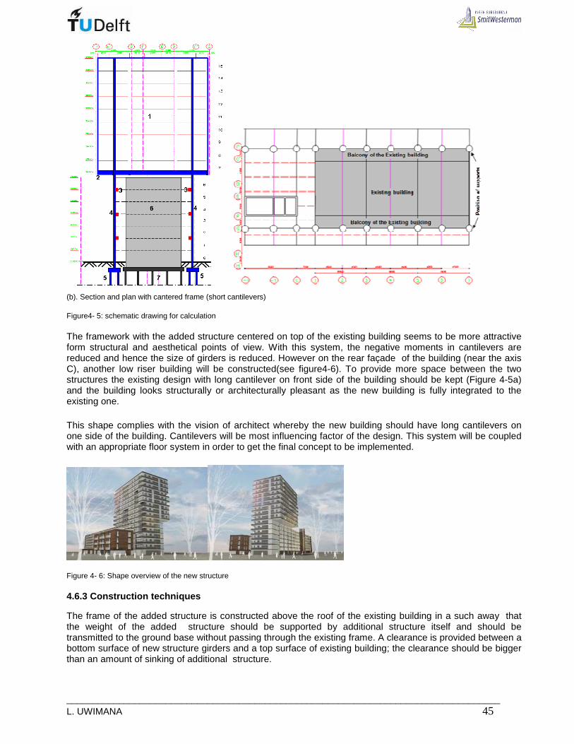
___________________________________________________________________________________ L. UWIMANA 45
(b). Section and plan with cantered frame (short cantilevers) Figure4- 5: schematic drawing for calculation The framework with the added structure centered on top of the existing building seems to be more attractive form structural and aesthetical points of view. With this system, the negative moments in cantilevers are reduced and hence the size of girders is reduced. However on the rear façade of the building (near the axis C), another low riser building will be constructed(see figure4-6). To provide more space between the two structures the existing design with long cantilever on front side of the building should be kept (Figure 4-5a) and the building looks structurally or architecturally pleasant as the new building is fully integrated to the existing one.
This shape complies with the vision of architect whereby the new building should have long cantilevers on one side of the building. Cantilevers will be most influencing factor of the design. This system will be coupled with an appropriate floor system in order to get the final concept to be implemented.
Figure 4- 6: Shape overview of the new structure 4.6.3 Construction techniques The frame of the added structure is constructed above the roof of the existing building in a such away that the weight of the added structure should be supported by additional structure itself and should be transmitted to the ground base without passing through the existing frame. A clearance is provided between a bottom surface of new structure girders and a top surface of existing building; the clearance should be bigger than an amount of sinking of additional structure.

_____________________________________________________________________________ 46 MSc Thesis
In order to enhance the stability of the newly added story-adding supporting frame columns, they are connected to each other lengthwise along the existing building at the level of every two corresponding floors place thereof by means of the steel beams [12]. In transverse direction these supporting columns should also be connected to the floor diaphragm of the existing building to reduce the buckling length of columns.
It is understood that the structure of the existing building is basically stable after many years of use, so that it may be deemed a non-deforming rigid body. The additional structure, at an early stage of use, may present sinking of foundation and self-deformation of the structure members after being subjected to load, resulting in a vertical relative displacement, between the new and existing buildings. Consequently, if no appropriate measures are taken, or no specific connections are provided between the existing and new buildings, but rather, a conventional rigid connection is still employed, the weight of the new building would surely press down on the existing building resulting in a confusion of route of force transmission and the increase of stress within the existing and new structures.
For that reason , certain clearance between the bottom surface of the additional frame supporting girders an the top surface of the existing building, particularly as the connectors between new and existing structures employed between the new and existing buildings are oriented pivoted bearings. The connection between new and existing frame enhances the stability of the new structure and the integrity with the existing building [12].
The ground base on site is not rock bedding; isolated foundation under columns and strip foundation are not possible. Pile foundation is the only possible option but piles will be installed new existing building, drilled or bored piles can be used. It is not allowed to use driven piles to avoid disturbance of the already settled foundation of existing building. [12]

___________________________________________________________________________________ L. UWIMANA 47
5. FLOOR SYSTEM
After deciding on appropriate frame, the next step is to choose an economic structural floor system to satisfy all the design constraints. The choice depends on the span of the floor and function of the building. According to high-rise [6], for spans up to 12-15m, simple universal beams with composite deck or precast floor are likely to be most economical. Above 15m, composite steel trusses or fabricated girders will be necessary. As the span increases, the depth and weight of the structural floor increases, and for spaces in excess of 15m, span depth predominates because of the need to achieve adequate rigidity. Figure 5-1 shows the economical way of choosing the floor system based on span.
Figure5- 1: Choice of floor system according to span As the maximum span for floor units is 4, 5 m (between axes 1 and 7) and 8,5m between axes -1 and 0, composite floor and precast floor units seem to be adequate solution.
5.1 System with composite deck slabs
The recent growth in the use of structural steel work for multi-storey buildings has been largely the result of development in the design and construction of structural floors consisting of simply supported universal beams acting compositely with a thin concrete slab supported on a metal deck. In this system, a metal decking spans between secondary steel beams. Steel studs are welded through the decking onto the flange of the beam below to form a connection between steel beam and concrete slab. The obtained slab is shallow with reduced volume of concrete which lead to a very light structure.
Figure5- 2: Composite floor system (Shallow)[11] The other type of composite system is the use of deep floor system (Slimdek) whereby the steel sheeting is put on bottom flange of the main beam, and the secondary beams are not necessary (Figure5-3).
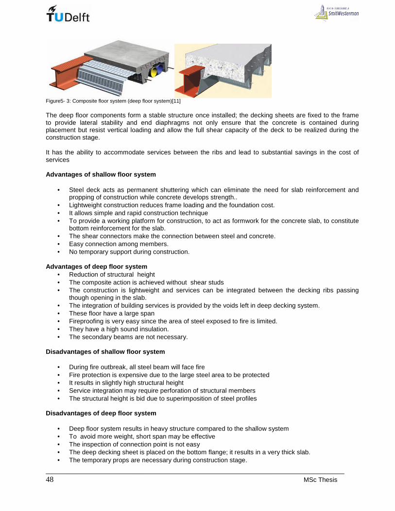
_____________________________________________________________________________ 48 MSc Thesis
Figure5- 3: Composite floor system (deep floor system)[11] The deep floor components form a stable structure once installed; the decking sheets are fixed to the frame to provide lateral stability and end diaphragms not only ensure that the concrete is contained during placement but resist vertical loading and allow the full shear capacity of the deck to be realized during the construction stage. It has the ability to accommodate services between the ribs and lead to substantial savings in the cost of services Advantages of shallow floor system
• Steel deck acts as permanent shuttering which can eliminate the need for slab reinforcement and propping of construction while concrete develops strength..
• Lightweight construction reduces frame loading and the foundation cost. • It allows simple and rapid construction technique • To provide a working platform for construction, to act as formwork for the concrete slab, to constitute
bottom reinforcement for the slab. • The shear connectors make the connection between steel and concrete. • Easy connection among members. • No temporary support during construction.
Advantages of deep floor system
• Reduction of structural height • The composite action is achieved without shear studs • The construction is lightweight and services can be integrated between the decking ribs passing
though opening in the slab. • The integration of building services is provided by the voids left in deep decking system. • These floor have a large span • Fireproofing is very easy since the area of steel exposed to fire is limited. • They have a high sound insulation. • The secondary beams are not necessary.
Disadvantages of shallow floor system
• During fire outbreak, all steel beam will face fire • Fire protection is expensive due to the large steel area to be protected • It results in slightly high structural height • Service integration may require perforation of structural members • The structural height is bid due to superimposition of steel profiles
Disadvantages of deep floor system
• Deep floor system results in heavy structure compared to the shallow system • To avoid more weight, short span may be effective • The inspection of connection point is not easy • The deep decking sheet is placed on the bottom flange; it results in a very thick slab. • The temporary props are necessary during construction stage.

___________________________________________________________________________________ L. UWIMANA 49
5.2 System made by Universal beams with precast con crete floors(Hollow core slab).
Hollow core slab units are made of either reinforced or prestressed concrete with longitudinal cores of which the main function is to reduce the weight of the floor-Figure 5-4. The elements are available in different depth in order to satisfy various performances needs for span and loading. The prestressed units are the most used in multistory building. They are normally 120mm wide and up to 20m long. The actual unit width is usually 3 to 6 mm less than the normal size to allow for construction tolerances. Prestressed hollow core units are mostly use in public building such as office, hospital, schools etc. However they rare also used in apartment buildings because of the favorable cost rate and the fast erection. Prestressed hollow core units are manufactured using either a long line extrusion or a slip forming process. The degree of prestressing, strand pattern and depth of unit are the main design parameters.
Figure5- 4: Precast and prestressed floor units Advantages
• Fewer floor beam since precast floor units can span up to 6 to 8m without difficulty and no propping is required.
• Shallow floor construction can be obtained by supporting precast floor units on shelf angles. • Fast construction because no time is needed for curing and the development of concrete strength. • High fire and sound resistance
Disadvantages
• Composite action not ready achieved without a structural floor screed ( structural topping). • Heavy floor units are difficult to erect in many locations and require use of a tower crane which may
have implications on the construction program.
5.3 System with Bubble Deck floor
Bubble Deck is a flooring method of virtually eliminating concrete from the middle of a floor slab not performing any structural function, thereby dramatically reducing structural dead weight.
Figure5- 5: Bubble deck floor

_____________________________________________________________________________ 50 MSc Thesis
Void formers in the middle of a flat slab eliminates 35% of a slabs self-weight removing constraints of high dead loads and short spans. Incorporation of recycled plastic bubbles as void formers permits 50% longer spans between columns. Combination of this with a flat slab construction approach spanning in two directions; the slab is connected directly to in-situ concrete columns without any beams Advantages
• Design freedom: flexible layout easily adapts to irregular and curved plan layouts. • Reduced dead weight: 35% removed allowing smaller foundation sizes. • Longer spans between columns: up to 50% further than traditional structures. • Down stand beams eliminated: quicker and cheaper erection of walls and services. • Load bearing walls eliminated: permit lightweight building envelopes. • High fire resistance
Disadvantages
• Due to void, the bending and punching shear resistance are reduced • Services cannot be integrated the structural height
5.4 System with Lattice Girder Floors ( Reinforced composite floor plates)
These floor units are used as permanent precast concrete formwork to In-situ concrete slabs. This type of composite floor is equally suited to use in almost every building type; masonry, steel or concrete structures and particularly those with progressive collapse considerations.
Figure5- 6: Lattice girder floor These floor slabs comprise a 50 to 70mm thick precast concrete soffit slab, containing individually designed main and transverse reinforcement cast on steel moulds giving a good soffit finish ready for direct decoration after normal preparatory treatments. Lattice girders are cast into the slab to provide a mechanical fixing between the precast unit and the In-situ concrete. These girders provide rigidity to the unit during transportation and their placement onto the prepared bearings. Advantage :
• The main advantages of this system , compared to the traditional cast-in-situ floors are , that, apart from the props, no mould have to be used and most of the reinforcement is incorporated in the precast plate.
• The construction time is reduced and the good finishes of the whole floor are achieved due to the smooth floor soffit.
• It behaves as normal concrete floor and therefore it has a high sound and fire resistance

___________________________________________________________________________________ L. UWIMANA 51
Disadvantage These kinds of floor are heavy and therefore the cost of supporting members as well as the foundation is much more.
5.5 Selection of floor system
Selection of floor system is based on structural load, method of construction, accommodation of services, fire safety, erection speed and comfort of occupants. In this case study, the building should have sufficient sound insulation since it is used for residential purposes, therefore sufficient mass should be considered when selecting the floor type and eventually the erection speed. Solid slab (lattice girder) and Bubble deck will not be selected. The first is very heavy whereas the second is not strong enough for out- of -plane actions. Both floor system cannot accommodate services and require too much site works. In composite floor system, one can see that the span between support columns is 14m; deep floor system cannot be used due its high depth and consequently enormous weight. The system with shallow floor reduces floor weight and the secondary beams minimize the overall deflection of the whole floor. However, the structural height becomes too big and field works are enormous. Finally, Hollow core slab units present lot of advantages and can be adapted to the entire structure which will facilitate the construction works.

_____________________________________________________________________________ 52 MSc Thesis

___________________________________________________________________________________ L. UWIMANA 53
6. DESIGN ALTERNATIVES BASED ON FLOOR FRAMING SYSTEM
In this chapter, various alternatives will be made based on floor framing system from axes 1 to 7. This is a governing part of the building; it is where the new structure will be put on top of the existing building. The part form axes -1 to 0 can be designed by taking into account the presence of the core and load transfer system. The floor structure forms horizontal rigid planes. They stiffen and join the vertical building structures, allowing the building to respond to forces as closed unit. The floor framing transmits gravity and lateral loads to the columns and / or walls. The layout of the floor structure is of great importance because it determines the direction of flow of wind and gravity forces, thus influences the geometry of the building skeleton. This part will discuss the floor structures from the following point of view:
• The floor framing as related to common structural building systems and as a distributor of gravity forces.
• The floor framing as a distributor of lateral forces The new building; the additional parts to the sides and the top of the existing building has a floor area of 37,1m x 19,9m (Figure 7-1). From the layout of the new building, an optimum framing should be in transverse direction so that the frame put there may have two possibilities of being used for carrying gravity loads as well as lateral loads.
Figure 6- 1: Floor area of the new building (from 7th to 15th floor) The most effective floor framing system is transverse framing [9]. A number of alternatives will be produced and in each alternative the number of intermediate supports is varied which will increase the possibilities of making the floor structure of the new building. In transverse frame systems, the gravity forces are distributed to the internal frame spanning the width of the building. Thus, the frame will resist not only the gravity but also the primary lateral forces. This capability of restraining lateral forces, shows that the transverse or cross frames are the most efficient to form the floor structure.
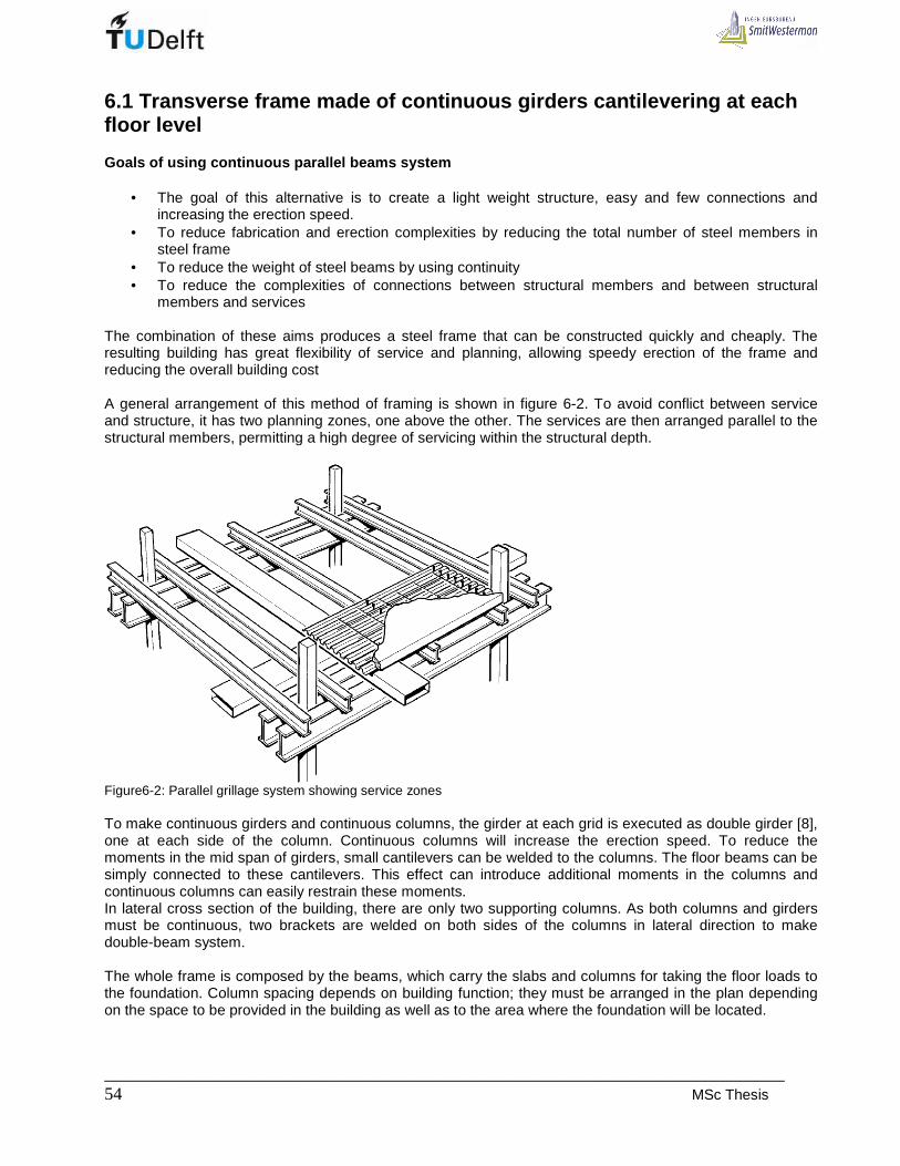
_____________________________________________________________________________ 54 MSc Thesis
6.1 Transverse frame made of continuous girders can tilevering at each floor level
Goals of using continuous parallel beams system
• The goal of this alternative is to create a light weight structure, easy and few connections and increasing the erection speed.
• To reduce fabrication and erection complexities by reducing the total number of steel members in steel frame
• To reduce the weight of steel beams by using continuity • To reduce the complexities of connections between structural members and between structural
members and services The combination of these aims produces a steel frame that can be constructed quickly and cheaply. The resulting building has great flexibility of service and planning, allowing speedy erection of the frame and reducing the overall building cost A general arrangement of this method of framing is shown in figure 6-2. To avoid conflict between service and structure, it has two planning zones, one above the other. The services are then arranged parallel to the structural members, permitting a high degree of servicing within the structural depth.
Figure6-2: Parallel grillage system showing service zones To make continuous girders and continuous columns, the girder at each grid is executed as double girder [8], one at each side of the column. Continuous columns will increase the erection speed. To reduce the moments in the mid span of girders, small cantilevers can be welded to the columns. The floor beams can be simply connected to these cantilevers. This effect can introduce additional moments in the columns and continuous columns can easily restrain these moments. In lateral cross section of the building, there are only two supporting columns. As both columns and girders must be continuous, two brackets are welded on both sides of the columns in lateral direction to make double-beam system. The whole frame is composed by the beams, which carry the slabs and columns for taking the floor loads to the foundation. Column spacing depends on building function; they must be arranged in the plan depending on the space to be provided in the building as well as to the area where the foundation will be located.

___________________________________________________________________________________ L. UWIMANA 55
The main supporting columns are put along the sides of the existing building because it is not possible to put columns through the existing building [12]. The means of load transfer will be discussed and must match with the floor system. This structural solution consists of floor girders with cantilevers at each floor level. The resulting girder height, according to the method of additional deflection [24] will be around 550mm, since the span is 14115mm and cantilever of 5,785 m. Shape Apparently, shape of the structure is adapted to the shape designed by the architect .But some internal spaces such as corridor will be altered due to the presence of bracing members in braced frames. Another change is the increase of the number of frames; for the new design frame in axis -1’, 2, 4 and 6 (Figure 6-3) are inserted in order to reduce the load carried by columns and therefore to have less impacts on adjacent existing foundations. In longitudinal direction, the floor is divided into 4, 5m and 4, 0 m grids (Figure 6-3), with respect to the subdivision of the apartment. In transverse direction, the subdivision depends on the available spaces, the function of the building, the location of structural members (load bearing members) and bracing systems.
(a) Plan for Floors 1 to 6
(b) Plan for Floors 7 to 15

_____________________________________________________________________________ 56 MSc Thesis
(c). Section in axes 1 to 7 (d) Section in axes -1 to 0
Figure6- 3: Transverse frame made of continuous double girder Supporting The structure will be supported by columns located near the existing building and bring the load of the superstructure to the new foundation located next to the existing foundation. The columns are arranged by following the grid of the existing building, the front columns will be heavily loaded due to the long cantilever load. In longitudinal direction, columns are arranged in axes G and C (Figure 6-3). In part between axes -1 and 0, vertical load is carried by columns and concrete core. Stability The stability of the whole structure can be assured by concrete core, braced frames and existing building. When braced frames are used It is important that the structure possesses sufficient stiffness; by vertical braced frame which consist of beams, columns, and stiff diagonal braces that perform like shear walls. Joining the columns in longitudinal direction and connection columns to the existing building’s slab at each floor level, will make the new structure more stable. The columns work together and resist lateral movement and lateral displacement by bending. With diagonal bracings, the horizontal loads are resisted through tension and compression forces in the braces. Force distribution In frames 1 to 7, the load coming from the floor is transferred to the spine beams and then to columns and finally to the foundation. The mechanical model for spine of this alternative is shown in Figure 6-4 where two scenarios (firstly with variable load on cantilever and secondary variable load on part between supports) can be analysed in order

___________________________________________________________________________________ L. UWIMANA 57
to calculate the required beam size to be used. In this method the collaboration of the entire frame is not considered only unfavourable situation of individual beam is taken into account. However by coupling the edges of the beam with a column, the system may respond much better to the loading.
Figure6- 4: Spine beam models From Appendix 3 and 6; it has been obtained that when live load is placed between supports a big beam
section would be required .The moment of inertia equal to: 105,8.10
span
Iδ
=
Where: I = required moment of inertia spanδ = deflection in mid-span
Secondly when live load is on cantilever, a small size can be used; the section depends on this moment of
inertia:103,27.10
span
Iδ
= .
The worst case scenario has to be considered; that is why the first case will be taken into account when deciding on beam section to be used.
• Required cantilever to field ratio. It possible to make a continuous girder by resting it to the console welded on one side of the column. The cantilever induces negative moment in beam, therefore the span and cantilever should have an optimum ratio to avoid the enormous moment in girder. The best ratio of cantilever to span is 0, 42 [13]
a=0,291 b=0,709.L
sup
span
M
M

_____________________________________________________________________________ 58 MSc Thesis
2 2 2sup
2 2 2sup
1 1(0,291 ) 0,0423
2 21 1 1 1
(0,709 ) 0,0423 0,238 2 8 2span
M qa q l ql
M qb M q l ql
= ⇒ =
= − ⇒ − =
Favorable cantilever-field ratio
Cantilever beam system
The maximum field moment in the girder is M span= 1/8 q.b2 and the support moment is M support =1/2 q.a2.
2sup
1 1
8 2spanM qb M= − or 2 21 1
8 2spanM qb qa= −
As,
2sup sup sup
2 2 2 2 2sup
2 2
1 1
8 23 1 3 1 1 3 1
2 8 2 2 8 4 81
0,4086
spanM M M qb M
M qb qa qb a b
a b a b
= ⇒ = −
= ⇒ = ⇒ =
= ⇒ =
The actual ratio of cantilever to span is 57850,409
14115
aa b
b= ⇒ = ; this is slightly bigger than 0,408b obtained
before but less than 0,42b considered as the maximum cantilever length [13]
In frames -1 to 0, the presence of concrete core brings problem in handling cantilever. Suspended system can be used to carry the cantilever part ( Figure 6-3d). The roof can be used to build system which transfers a heavy bending structure. But the height of building increases and the erection is more complicated. Connections Strong building connections allow forces and displacements to be transferred between vertical and horizontal building elements. Furthermore, strong connections increase the overall building strength and stiffness by allowing all of the building elements to act together as a unit. Inadequate connections represent a weak link in the load path of the building and are a common cause of damage and collapse when building is subjected to the huge horizontal loading. In this project, the important connections are the following:
- Beams to columns connection - Beam to floor slab connection - Columns to foundation connection - Connection of columns of new structure to the existing building
Connections between beams and columns are made by bolting through the beam web to bracket welded to the columns as shown in Figures 6-5. For a double spine beam, the brackets are symmetrical about the column major axis.)

___________________________________________________________________________________ L. UWIMANA 59
Figure6- 5: Connection of spine beams to columns Fixing beams on brackets welded on two sides of the columns ,results in continuous beam, therefore the columns will be continuous too. For erection purposes, a temporary support is put at the edges of the cantilever and then a column joining the edges of cantilevers for all floors can be put. There are three possibility of connecting the beam edges to the edge column: -By hinge connection - Moment connection - Moment connection plus additional hinge. The latter is optimum due to the small deflection. To reduce the moments in the mid spans, of the girders small cantilevers are welded to the columns. The floor beams are simply connected to these cantilevers. Advantage and disadvantages of continuous beam syst em
− High speed of construction − Few connection − Clear flow of forces − But to stabilize the building may be complicated because of the lack of concrete core and the bracings
may have large dimensions. − Composite floor system is not a good solution for such particular structure because on cantilever side the
compressive stresses will be in steel girder and tensile stresses will be in the reinforcement of the concrete. The negative moment capacity will not increase much compared to the moment capacity of the steel girder.
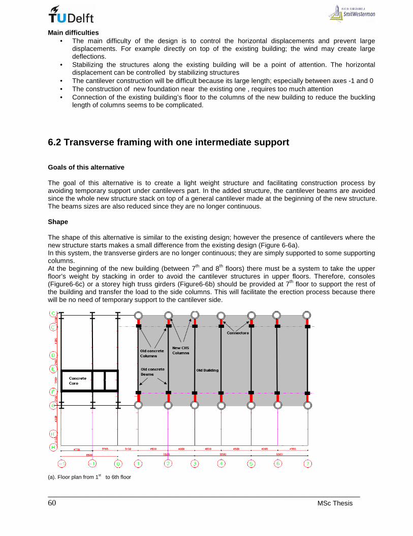
_____________________________________________________________________________ 60 MSc Thesis
Main difficulties • The main difficulty of the design is to control the horizontal displacements and prevent large
displacements. For example directly on top of the existing building; the wind may create large deflections.
• Stabilizing the structures along the existing building will be a point of attention. The horizontal displacement can be controlled by stabilizing structures
• The cantilever construction will be difficult because its large length; especially between axes -1 and 0 • The construction of new foundation near the existing one , requires too much attention • Connection of the existing building’s floor to the columns of the new building to reduce the buckling
length of columns seems to be complicated.
6.2 Transverse framing with one intermediate suppor t
Goals of this alternative The goal of this alternative is to create a light weight structure and facilitating construction process by avoiding temporary support under cantilevers part. In the added structure, the cantilever beams are avoided since the whole new structure stack on top of a general cantilever made at the beginning of the new structure. The beams sizes are also reduced since they are no longer continuous. Shape The shape of this alternative is similar to the existing design; however the presence of cantilevers where the new structure starts makes a small difference from the existing design (Figure 6-6a). In this system, the transverse girders are no longer continuous; they are simply supported to some supporting columns. At the beginning of the new building (between 7th and 8th floors) there must be a system to take the upper floor’s weight by stacking in order to avoid the cantilever structures in upper floors. Therefore, consoles (Figure6-6c) or a storey high truss girders (Figure6-6b) should be provided at 7th floor to support the rest of the building and transfer the load to the side columns. This will facilitate the erection process because there will be no need of temporary support to the cantilever side.
(a). Floor plan from 1st to 6th floor
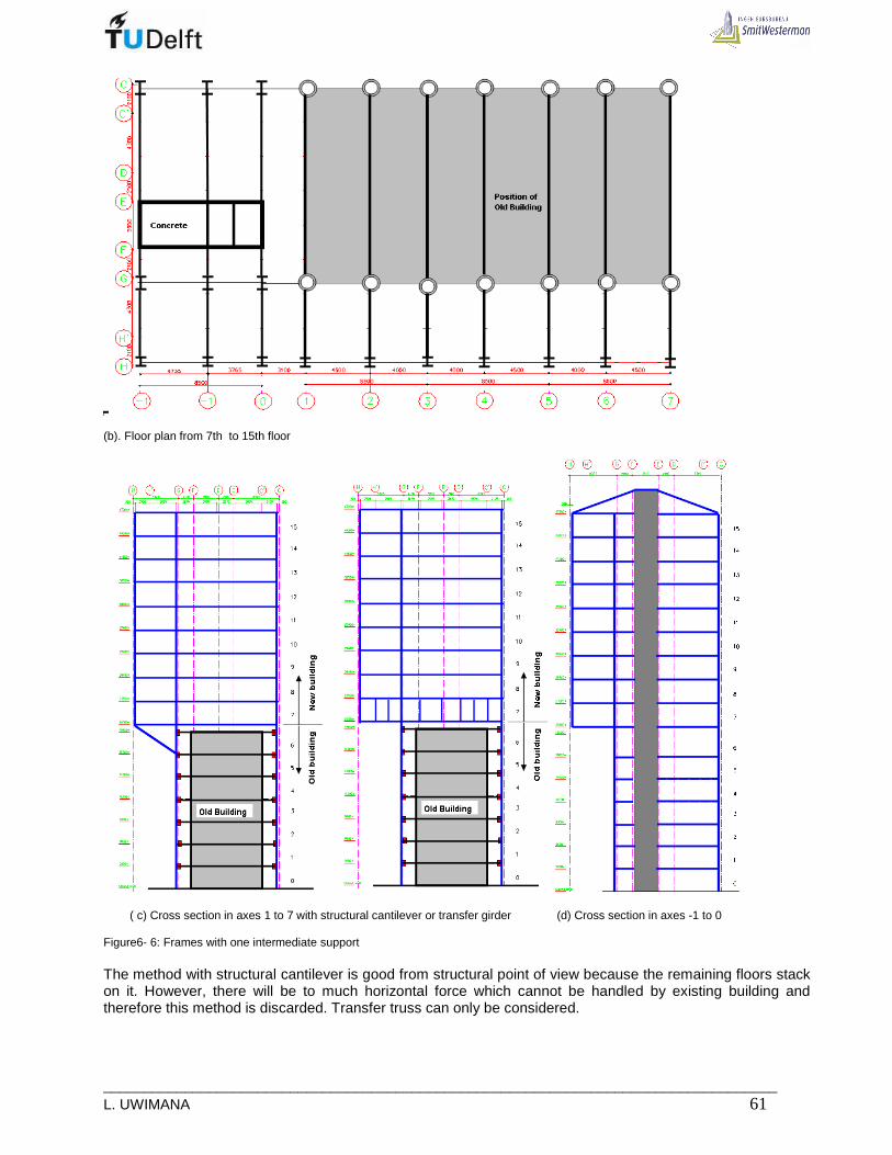
___________________________________________________________________________________ L. UWIMANA 61
(b). Floor plan from 7th to 15th floor
( c) Cross section in axes 1 to 7 with structural cantilever or transfer girder (d) Cross section in axes -1 to 0 Figure6- 6: Frames with one intermediate support The method with structural cantilever is good from structural point of view because the remaining floors stack on it. However, there will be to much horizontal force which cannot be handled by existing building and therefore this method is discarded. Transfer truss can only be considered.

_____________________________________________________________________________ 62 MSc Thesis
Supporting The new structure will be supported by columns located near the existing building and bring the load of the new structure to the new foundation located next to the existing foundation. The columns are arranged by following the grid of the existing building, the front columns will be heavily loaded due to the long cantilever load. In longitudinal direction, columns are arranged in axes G and C (Figure 6-6). The additional structure is supported by transfer truss girders located at each transversal axis between 7th and 8th floors .These truss girders transfer the load to the supporting columns and then to the foundation.
• Choice of truss girder type
The truss girders are capable to carry enormous load and take them to the side columns. This method is very useful because what is needed is to bridge the existing building. The trusses are put between 7th and 8th floor and are one storey high-Figure 6-6, they are located at every transversal axis The trusses have to be stiff enough and should not obstruct the building spaces such as rooms, opening, and corridors. The web members should coincide with the axes where the columns for wall framing will be located. As the top and bottom chords carry the slabs; so they act as composite trusses. Although the fabrication cost of truss girders is greater than any other forms of construction, they do have the following advantages.
• They do not require any special fabrication equipment. • They offer plenty of spaces to accommodate services
The principal disadvantage, other than the increased fabrication cost, is that they are difficult to protect from fire. Sprayed protection systems are messy while the alternative of wrapping is labor intensive. The trusses with triangulations, cause hindrance in some locations on 7th floor; some openings are closed by the oblique struts. To avoid this, Vierendeel truss was proposed to be the solution for the truss girder-Figure 6-7. However, Vierendeel girder brings some complications in joint manufacture since they have to resist enormous bending moments.
(a) Normal truss (b) Vierendeel truss Figure6-7: Truss girder between 7th and 8th floor for axes 1 to 7 Stability As the previous alternative, the horizontal load can be taken by the concrete core working together with braced frames put in one or several transverse axes and existing building. The longitudinal stability can be assured by the concrete core only. Force distribution From axes 1 to 7, the floor load is taken to the floor beam and then to the main beams which channel it to the columns. The columns take the load to the transfer girder and finally to the supporting columns and to the

___________________________________________________________________________________ L. UWIMANA 63
foundation. From the structural point of view, this is the best solution, the floor levels above the cantilever, the other floors can easily stack on the first floor of the added structure. The loads go directly to the foundation. The erection is easy because of the stack from the bottom to the top. The beams can be modelled as simple supported beam (Figure 6-8) and hence the small sizes would be adequate for this system.
Figure6- 8: Beam model for system with one intermediate support In axes -1 to 0, the loads are similarly transferred as in previous alternative because the structure in that part remains unchanged. Connections Simple connections between beams and columns would be used. If a general cantilever is to be used, special attention would be paid for connection the 7th floor main beams to the supporting columns. If transfer girder would be used, between 7th and 8th floors, twin transfer girders would be used in order to make them continuous and they will be connected to the supporting columns using the brackets welded to the columns. Advantage
- Continuous girders are avoided in top floors - Small beam size can be used since they are not continuous - The whole cantilever part stands on structural transfer truss made at the beginning of the new
structure and hence during construction no temporary support will be used.
Disadvantages
• The transfer truss girder systems seem to be not economical in terms of fabrication, connections and fire protection
• The support columns on cantilever side will not be continuous and will require complicated connections.
Main difficulties
• The control and limiting horizontal deflection • Huge negative moment in transfer truss girder • The cantilever construction will be difficult because its large length • The construction of new foundation near the existing one , requires too much attention • Connection of the existing building’s floor to the columns of the new building • Fabrication of transfer truss girders and their fire protection measures

_____________________________________________________________________________ 64 MSc Thesis
6.3 Transverse floor framing with two or more inter mediate supports
Goals The goal of this alternative is the construction of a light structure by using many columns fixed on transfer girders. Short spans beams with small depth will be used. Shape In this alternative, the solution to carry the cantilever load is by using transfer truss girders in the first storey of the added structure (Figure 6-9). The floors above stack on those girders for both cantilever portions as well as the parts between the supporting columns. The loads are taken by the girder and carried directly to the columns which ferry them to the foundation. The shape for this structure is the same as the existing shape from architectural design.
(a). Floor plan from 1st to 6th floor
(b). Floor plan from 7th to 15th floor
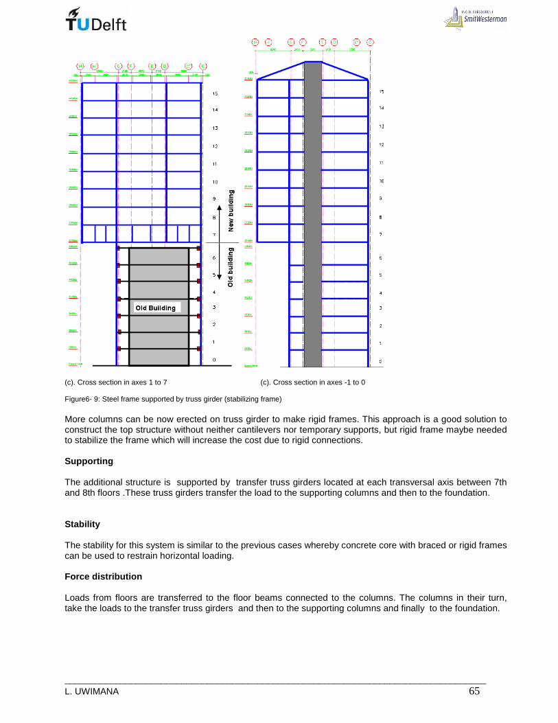
___________________________________________________________________________________ L. UWIMANA 65
(c). Cross section in axes 1 to 7 (c). Cross section in axes -1 to 0 Figure6- 9: Steel frame supported by truss girder (stabilizing frame) More columns can be now erected on truss girder to make rigid frames. This approach is a good solution to construct the top structure without neither cantilevers nor temporary supports, but rigid frame maybe needed to stabilize the frame which will increase the cost due to rigid connections. Supporting The additional structure is supported by transfer truss girders located at each transversal axis between 7th and 8th floors .These truss girders transfer the load to the supporting columns and then to the foundation. Stability The stability for this system is similar to the previous cases whereby concrete core with braced or rigid frames can be used to restrain horizontal loading. Force distribution Loads from floors are transferred to the floor beams connected to the columns. The columns in their turn, take the loads to the transfer truss girders and then to the supporting columns and finally to the foundation.

_____________________________________________________________________________ 66 MSc Thesis
Connections In top stories simple or rigid connections (depending on number of columns used) are used between beams and columns. The top and bottom chords of the transfer truss girders are also the main beams for the floor system; the transfer girders must be rigidly connected to the columns. Advantage
• This is a better method to carry the cantilever load • The entire building lay on transfer girders and therefore from 8th floor , the main beam are simply
connected to the columns. • Cantilevers are avoided on the rest of the building • Member size can be reduced since many columns can be erected • The construction is easy because the additional structure is supported by the transfer truss girders
Disadvantages
• The fabrication of truss girder may be very expensive • Using truss girder on 7th floor can obstruct some path ways • In Vierendeel truss, as the joints have to resist huge moments on 7th floor, enormous members will
be required to make the truss which makes the system more expensive. • Continuous truss girders are required to make cantilevers and hence columns in axis G are no longer
continuous.
Main difficulties
• The main difficulty is based on bracing method for stabilizing the building against horizontal loading and controlling the horizontal deflection
• Connection of columns to transfer girders and connection of support columns to transfer girders • Huge negative moment in transfer truss girder • The cantilever construction will be difficult because its large length • The construction of new foundation near the existing one , requires too much attention • Connection of the existing building’s floor to the columns of the new building • Fabrication of transfer truss girders and their fire protection measures
6.4 Transverse floor framing with two concrete wall s in axis -1 and 0
Goals The main goal for this system is to facilitate the construction of cantilever section where the concrete core is located and to enhance the stability of the whole building. Functional concept This part of the building has three functions, namely:
• Providing access to both new and existing building and new apartments. It has a concrete core which accommodates the staircase and the lift shaft.
• New rooms are housed in this part • To stabilize the building
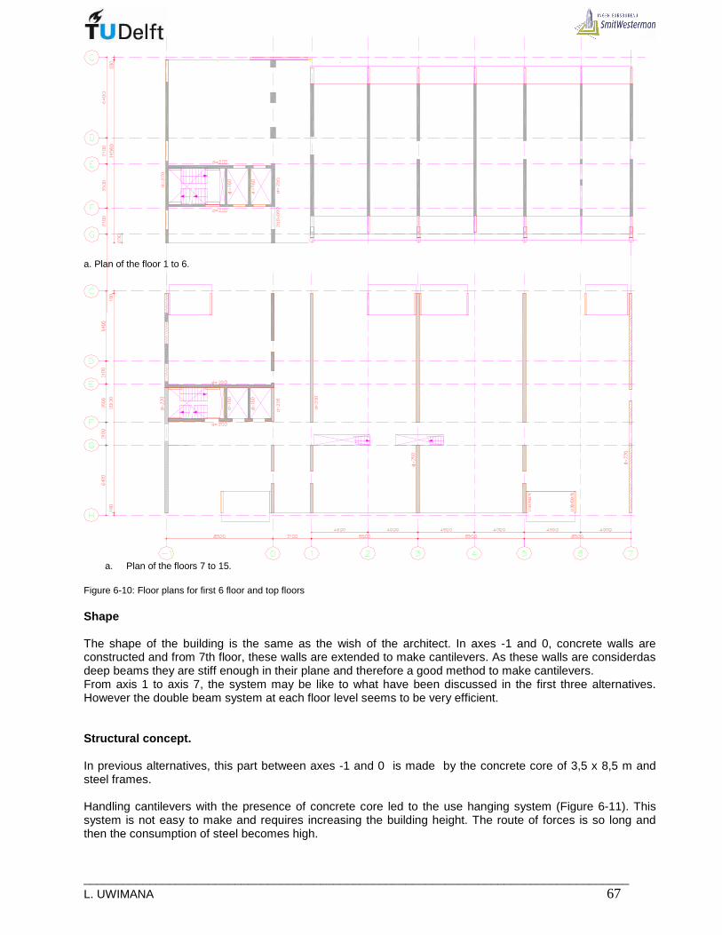
___________________________________________________________________________________ L. UWIMANA 67
a. Plan of the floor 1 to 6.
a. Plan of the floors 7 to 15.
Figure 6-10: Floor plans for first 6 floor and top floors Shape The shape of the building is the same as the wish of the architect. In axes -1 and 0, concrete walls are constructed and from 7th floor, these walls are extended to make cantilevers. As these walls are considerdas deep beams they are stiff enough in their plane and therefore a good method to make cantilevers. From axis 1 to axis 7, the system may be like to what have been discussed in the first three alternatives. However the double beam system at each floor level seems to be very efficient. Structural concept. In previous alternatives, this part between axes -1 and 0 is made by the concrete core of 3,5 x 8,5 m and steel frames. Handling cantilevers with the presence of concrete core led to the use hanging system (Figure 6-11). This system is not easy to make and requires increasing the building height. The route of forces is so long and then the consumption of steel becomes high.

_____________________________________________________________________________ 68 MSc Thesis
Figure6- 11: Floor system with double girder for floor level 7 to 15 and cross section in axes -1, -1’ and 0 The remedy for this issue is to use concrete walls in axis -1 and 0. As these walls have a big number of openings (Figure6-14), they cannot be used to take the horizontal loads; they will only take the vertical loads and providing cantilevers at each floor level from 7th to 15th floor. Horizontal loads will be restrained by the concrete core as well as the braced frames between axes 1 and 7. The easy way of making the floor system, is by using hollow core slab units which can be simply put on consoles made on walls. (See figure6-12 and 6-13).
a. Floor plan for ground level to floor 6

___________________________________________________________________________________ L. UWIMANA 69
b .Floor plan for top floors. Figure 6- 12: Floor plans
Figure 6- 13: Construction details of the floor system
Wall -1 Wall 0 Figure 6-14: Cross section showing openings in walls

_____________________________________________________________________________ 70 MSc Thesis
According to VBI [ 29] , the HCS260 (Hollow core slab of 260mm deep) should be used between axes -1 and 0 since the floor span is closer to 10m , the floor units will be laid on consoles provided on concrete walls. For the remaining part of the building HCS200 will be used, these units will be put on top of the spine beams and finally, the floor units will be joined by the structural topping to make floor diaphragm. Supporting The supporting system for this system is the same as what has been used in the first alternatives for the axes 1 to 7, but from axes -1 to 0, floor load are taken by concrete walls to the foundation. Stability The major stabilizing member is the concrete core, but braced frames are required on the other side of the building to avoid torsional deformations. The existing building as it is stiff in lateral direction; it can help in stabilizing the new structure. Force distribution and connection From axis 1 to axis 7, the force distribution and connections are the same as the force distribution in the first alternatives. In the part with walls, the floor units transfer their loads to the concrete walls which carry them to the foundation. At each floor level the wall can be modelled as a deep beam, very stiff in their plane and cannot easily be deflected when they are cantilevered. The floor units are simply laid on consoles provided on walls. Advantages
• The resulting structure is more stiff to restrain horizontal forces • Good method to make cantilevers between axes -1 and 0 • Concrete walls will facilitate making first 6-floors between axes -1 and 0 • No need of hanging system
Disadvantages
• The use of concrete wall limits the flexibility to make future modifications • Wall are heavy and require more foundation piles

___________________________________________________________________________________ L. UWIMANA 71
7. EVALUATION OF ALTERNATIVES
Firstly, a short summary about the goals and the difficulties of the elaborated alternatives will be given. After that, the principle of the Multi-Criteria Analysis (MCA) will be described. The selection, based on the rating of the alternatives, will then be made.
7.1 Summary of alternatives
Alternative 1: Structure with continuous parallel girders With a system of continuous parallel girders method, the girders run from one side of the existing building to the other and continue to the cantilevers. The girders are fixed on brackets welded on both side on the column which make the column to be also continuous. The use of hollow core slab system provides less weight which can be carried safely by the girders. The system is easy to erect, the sound as well as heat resistance are achieved due to the concrete layer. The stability, horizontal or/and vertical deflections, large foundation forces from the new structure are the governing factors of the design. Alternative 2: Structure with one intermediate support. Unlikely the previous system, this time the girders are simply supported because the cantilevers are supported by transfer girders made between 7th and 8th floors. There is no need of using double beam system since the cantilevers are supported and stack on transfer girders. The transfer girder may be in form of Vierendeel girders since oblique struts cause hindrance of some spaces. The fabrication of Vierendeel girder may be too expensive due to its joints capable to resist large moments brought by the top structure. Alternative 3: Structure with two or more intermediate supports This alternative is close to the previous one, and this also requires a transfer girder to support the entire added structure. The use of one story high transfer girder between 7th and 8th floors allows adding more columns. Then the result is to have moderate sizes of columns and transverse beams. It is also possible to make rigid frame once more columns are erected. Vierendeel transfer girder may also be preferred instead of normal truss. Alternative 4: Structure made of concrete walls (axis -1 and 0) and steel frame (axis 1 to 7) The sections between axes -1 and 0 in previous alternatives, the gravity loads are transferred to the foundation by hanging systems. But when concrete walls would be used, these walls can make cantilevers at each floor level since they are incorporated to the core no hanging system would be required.
7.2 Decision factors (criteria)
To decide which alternative will be elaborated, various views from different stakeholders (parts interested in the project) have to be analysed. The possible stake holders are the following:
• the architect • the structural engineer • the user(occupants) • the investor • the contractor • the Municipality • the people on the street(passer-by)

_____________________________________________________________________________ 72 MSc Thesis
Each part will be interested in different elements which have to be taken into account when deciding. There are five main elements that influence the decision namely aesthetical value, efficiency, technical value, functional requirements and costs.
Aesthetical value Aesthetical value is one of the sensitive points for the final results of the MCA. The architectural design is a key factor when looking at Aesthetic. For the architectural design it is chosen to compare the alternatives with the vision of the architects. The alternatives that are of the same shape of the architectural design therefore have a high score. This point of departure results in the fact that architectural value is based on the opinion of the architect, the municipality the passer- by people. This is the reference point of the architectural value-factor. Efficiency To be able to compare the alternatives in such a way that the efficiency of the design according to shape and force distribution, the factor efficiency is added to the criteria. This factor shows that the design seems to be efficient or not and can give a critical view on the architectural design. The parties that are interested in this factor are the structural engineer and, the contractor and to a lesser extend the architect. Technical value The technical value the designs is based on the technical difficulties and technical properties of each design. This factor is added to the MCA to be able to compare the technical difficulties of the designs. Functional requirements The main point of interest of residential building is the occupants. The structure must meet all the requirements namely thermal and sound comfort, privacy etc. Therefore the functional requirements are of great influence during initiation and design; especially for the engineer, municipality and the . Costs The costs of the structures are also an important factor. To estimate these costs is of course very difficult. Based on the insight in cost rates, estimation is made to what extend the alternatives differ in costs and where savings can be made. These estimations are roughly made but give an insight in the rates between the alternatives. For example the costs of the connections are based on the amount and difficulties of the connections.
7.3 The Multi-Criteria Analysis (MCA)
To make a well founded decision, a Multi-Criteria Analysis (MCA) will be done. The MCA is a tool to get insight in the suitability of the alternatives. This tool is based on the main factors influencing the suitability and gives an insight in the main differences between alternatives. From this MCA a few conclusions can be made. The main advantages and disadvantages of each of the alternatives are displayed in a surveyable way. The main subjects of this MCA are aesthetical value, efficiency, technical value, functional requirements and costs. These factors are not all of the same importance. To determine this importance it is useful to determine the most important parties influencing the design and their main interests. The passengers for example are not really interested in the technical requirements of the design, but are very interested in the functionality of the design. In analyzing the views of the possible parties in this project; there was no direct interview held with them , the author put himself in a place of each party order to determine the field of his/her interest.

___________________________________________________________________________________ L. UWIMANA 73
By using MCA, the members do not have to agree on the relative importance of the Criteria or the rankings of the alternatives. Each member enters his or her own judgments, and makes a distinct, identifiable contribution to a jointly reached conclusion. [21], [26] Weighting the Scores According to the Weights Assig ned to the Criteria The next step in the MCA process involves 'prioritizing' the criteria by assigning different rankings or weights. The weights can be assigned by the analyst, the decision maker or they can be based on the views of the stakeholders [22]. The importance of a criterion is called a weight; this is a matter of preference of stakeholders involved in the whole process of the project. All these views concerning possible criteria can be summarized in priority matrix (table 7-1). These priorities are ranked in terms of ordinal expression such as better, worse, favorable, less favorable etc. [26] In the following table (table 7-1), a global interest rating is done. The average value of each factor is calculated to make an estimation of the global interest. Table 7- 1: Priority matrix according to [26]
Party\Aspect Aesth. Value Efficiency Technical value Functional value Costs
Architect 10 7 8 8 4
Structural Engineer 6 10 10 7 7
Municipality 7 6 7 10 10
Users(occupants) 6 0 4 10 7
Passer-by 5 0 0 0 0
Investor 7 6 7 10 10
Contractor 4 8 10 4 7
Average 6,4 5,3 6,6 7,0 6,4 From this table, the functionality and technical value of the new structure seems to be the most important. The residents comfort, the feasibility or implementation of the structure are the basis of the design. The functionality and technique of the design are therefore important for all parties. The aesthetical design is also a very important factor. For the architect, municipality and the investor it is of great influence. The average weight factors will be used in Appraisal matrix. The discussed influence-factors can be divided in sub-factors that influence the value of the mentioned influence-factors [27]. The importance of these sub-factors, with regard to the main factors, is rated in the weight factor column. Each alternative is then rated by giving a value for each sub-factor regarding to the alternative. The higher the value, the better the alternative scores for the sub-factor. It is determined to what extend the alternative “scores” for each sub-factor. By calculating the average score (multiplied by the value of the main influence factor) the total score for each alternative, regarding to the main factor, can be calculated. By adding up these scores a total score for the design can be determined. [26], [27]

_____________________________________________________________________________ 74 MSc Thesis
Table 7- 2: Appraisal Matrix according to [26], [27] MCA Weight
factor
1. Aesthetical value 6.4
Shape/disturbance 5 3 15 3 15 3 15 3 15
Material appearance 4 4 16 2 8 4 16 4 16
Height of building 3 4 12 2 6 3 9 3 9
Facade appearance 5 4 20 3 15 4 20 4 20
Apartments 3 3 9 3 9 3 9 3 9
Average score 14.4 10.6 13.8 13.8
Total score AD 92 68 88 88
2. Efficiency 5.3
Weight of the structure 3 2 6 4 12 2 6 4 12
Shape/force distribution 4 3 12 4 16 3 12 4 16
Average score 9.0 14.0 9.0 14.0
Total score E 48 74 48 74
3. Technical 6.6
Ammount of connections 4 4 16 2 8 3 12 5 20Difficulty of theconnections 4 3 12 3 12 3 12 4 16
Foundation construction 5 3 15 3 15 3 15 3 15
Loads on foundation 4 1 4 4 16 2 8 3 12
Durability 5 5 25 4 20 5 25 5 25
Stability 5 4 20 3 15 4 20 4 20
Vertical stiffness 5 3 15 5 25 4 20 4 20
Horizontal stiffness 5 3 15 3 15 3 15 3 15
Service integration 4 2 8 4 16 2 8 5 20
Execution/Erection 4 3 12 2 8 5 20 4 16
Average score 14.2 15.0 15.5 17.9
Total score T 94 99 102 118
4. Functional 7.0
Thermal requirements 5 5 25 4 20 4 20 5 25
Acoustics requirements 5 5 25 4 20 3 15 4 20
Fire safety 4 4 16 2 8 3 12 4 16
Apartment layout 5 5 25 5 25 5 25 5 25
Access to new building 3 4 12 4 12 4 12 4 12
Connecting facilities 4 3 12 3 12 3 12 3 12
Average score 19.2 16.2 16.0 18.3
Total score F 134 113 112 128
5, Costs 6.4
Execution costs 4 4 16 3 12 5 20 4 16
Connection costs 4 4 16 2 8 4 16 5 20
Material costs 4 3 12 4 16 3 12 3 12
Average score 14.7 12.0 16.0 16.0
Total score C 94 77 102 102
Total score 462 431 453
Strucure with Continuous parallel beam systemStructure with one intermediate supportStructure with two or more intermediate supportsStructure with concrete walls in axis -1 and 0
511
Concept 1 Concept 2 Concept 3 Concept 4
The total score of each alternative is sensitive for changes in the valuation of all factors. The difference between alternatives has to be relatively large to be able to tell anything about the suitability of the alternatives. The differences in these scores look relatively small. Therefore some conclusions can be made by this MCA.

___________________________________________________________________________________ L. UWIMANA 75
7.4 Conclusion
The final score of the alternatives have to be interpreted with care. The differences among alternatives are relatively small but some alternatives seem to be less suitable for this particular project. The alternatives based on frameworks with one, two or more intermediate supports do not have a high score (Concept 2 and 3). The technical difficulties, functional requirements and the costs are the most important disadvantages of these alternatives. The major problem is based between axes -1 and 0 where hanging system would be required to transfer the loads to the foundation; hanging system pauses a lot of difficulties and consequently alternatives 2 and 3 would not be chosen. The alternative whereby, the framework between axes 1 and 7 are made of continuous girders (Concept1). scored also less. The cause is also technical difficult where the concrete core is located. Hanging system would be needed and hence this alternative would not be chosen. Finally a frame made of continuous steel columns and continuous double beam system in axes 1 to 7 and concrete walls in axes -1 and 0 has a highest score. It is a combination of concept 1(axes 1 to 7) and concrete walls in axes -1 and 0 The high score is due to technical solution of making cantilevers incorporated to the walls. The bending moments in concrete core reduce and the response to the horizontal load improves.

_____________________________________________________________________________ 76 MSc Thesis
___________________________________________________________________________________ L. UWIMANA 77
PART 2: STRUCTURAL DESIGN OF THE SELECTED ALTERNATIVE


___________________________________________________________________________________ L. UWIMANA 79
8. STABILITY SYSTEM OF THE SELECTED ALTERNATIVE
In this chapter, the stability for the selected structure will be designed. The process starts by verifying the capacity of concrete core alone and the core plus additional braced frames, and finally, the optimum method will be selected to stabilise the new structure. Although the primary function of the structure is to support vertical loads, it must incorporate a lateral stability system to resist horizontal forces, which commonly are wind loads, imperfection and, in some countries, earthquakes. The earthquake loads are disregarded in this project.
8.1 Stabilizing structures
8.1.1 Concrete Core
Elevator shafts (cores) are primary components for resisting both horizontal and gravity loading in multistory buildings structures. Reinforced concrete cores, comprise an assembly of connected shear walls forming a box section with openings that may be partially closed by beams or floor slabs. The moment of inertia of reinforced concrete core is large so that it is often adequate in itself to carry the whole of lateral loading. Usually when stiff cores are used to stabilize the buildings, they should preferably be located in the centre of the building, since it can expand freely in both directions. The torsion stability is then provided by the torsional rigidity of the core. In this project, the central core solution is impossible because of the old building. Therefore the core is built eccentrically in plan (Figure8-1) ; in this concept ,the core is the only one structure which should stabilize the entire building because the frames 1 to 7 old are not connected to the old building( see figure8-1 c)
(a) Floor plan for first six floors
(b) Floor plan for 7th to 15th floor Figure 8- 1: Floor plans and section when only core is used for stability
(c) Cross section in axis1 to 7, it shows no connection between
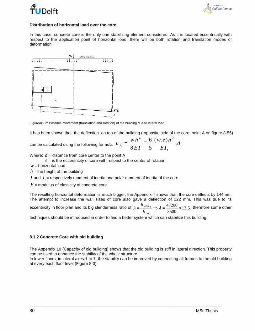
_____________________________________________________________________________ 80 MSc Thesis
Distribution of horizontal load over the core In this case, concrete core is the only one stabilizing element considered. As it is located eccentrically with respect to the application point of horizontal load; there will be both rotation and translation modes of deformation.
FigureA8- 2: Possible movement (translation and rotation) of the building due to lateral load
It has been shown that the deflection on top of the building ( opposite side of the core; point A on figure 8-56)
can be calculated using the following formula:
4 26 ( . ).
8 5At
w h w e hu d
E I E I= +
Where: d = distance from core center to the point A e = is the eccentricity of core with respect to the center of rotation w = horizontal load h = the height of the building
I and tI = respectively moment of inertia and polar moment of inertia of the core
E = modulus of elasticity of concrete core The resulting horizontal deformation is much bigger; the Appendix 7 shows that, the core deflects by 144mm. The attempt to increase the wall sizes of core also gave a deflection of 122 mm. This was due to its
eccentricity in floor plan and its big slenderness ratio of 4720013,5
3500building
core
h
bλ λ= ⇒ = ≈ ; therefore some other
techniques should be introduced in order to find a better system which can stabilize this building.
8.1.2 Concrete Core with old building
The Appendix 10 (Capacity of old building) shows that the old building is stiff in lateral direction. This property can be used to enhance the stability of the whole structure. In lower floors, in lateral axes 1 to 7, the stability can be improved by connecting all frames to the old building at every each floor level (Figure 8-3).

___________________________________________________________________________________ L. UWIMANA 81
(a) Floor plan for first six floors
(a) Floor plan for 7th to 15th floor Figure 8- 3: Floor plan showing concrete core and connection of new structure to the old building As the frames of the old building are filled with the masonry, they behave like braced frames [19], and therefore the set of frame and masonry in-fill contributes to the overall stability of the added structure. The frame of the old building can be modeled as braced frame with single diagonal [6] (see figure 8-4). The masonry in-fill play a big role in strengthening the old structure and this advantage help to stabilize the new
structure. The equivalent area of diagonal representing the in-fill is given by1
.10
L t , where L is the length of
diagonal and” t” is the thickness of wall. [6]
( c) Cross section 1 to 7

_____________________________________________________________________________ 82 MSc Thesis
(a) Frame with masonry in-fill (b) In-fill represented by diagonal strut
Figure 8-4: Masonry in-fill and its representation in old building
Distribution of horizontal load over stabilizing el ements The horizontal loads are distributed to the concrete core and to the frames of old building in the first 6-floors. As the old building is stiff in lateral direction, the loads restrained by the core is little but from 7th floor upward, the core take the entire horizontal load by itself.
• Upper part In the uper part of the building , the horiontal loads are only restrained by the core. As the core is eccentric, it is bubjected to translation as well as rotations forces.
,, .;
,1
.y iy transl i yn
y ii
IF W
I=
=∑
and
( ),
, ,2 2
, ,1
..
. .
y i iy rotation i Tn
y i i x i ii
I xF M
I x I y=
+∑
,y iI and ;x iI : moment of inertia of bracing structures i, in Y and X- direction
yW : Total lateral forces action on floor level
, .;y transl iF and , .;y rotation iF : Translation and rotation force acting on bracing structure i
ix and iy : Distance from rotation center to structure I, in X and Y – direction.
TM :Tortional moment .T yM W e= ; where e is the eccentricity
The rotation center coincides with the centroid of the core and then , the eccentricity with respect to the horizontal load becomes 14,3m (Figure8-5).

___________________________________________________________________________________ L. UWIMANA 83
Figure 8-5: Floor plan 7th to 15th showing only the core as bracing structure The resulting forces in core are enormous (see Appendix7) in such a way that they cannot be restrained by the core only.
• Lower part In the lower part of the building, the horizontal loads are taken by concrete core and existing building .The rotation center goes far from the core and the eccentricity reduces (figure8-6)
Figure 8-6: Location of rotation centre in plan (core and old building frames frame) in floor 0 to 7
The horizontal loads are shared among frames of old building and to the core. The core in this part is not heavily loaded. The calculations are made in Appendix 7 and the resulting contribution in restraining horizontal loads is shown in the flowing table.

_____________________________________________________________________________ 84 MSc Thesis
Table 8-1: Forces acting on bracing members
Upper
Translation Rotation Total force Height UDLKN KN KN m KN/m
W5 1137 48 1185 26,64 44Core 881 48 929 26,64 35
Lower
Translation Rotation Total force Height UDLKN KN KN m N/m
W1 276 193 469 20.56 23W2 276 120 396 20.56 19W3 276 55 331 20.56 16W4 276 10 286 20.56 14W5 276 83 359 20.56 17W6 276 148 424 20.56 21W7 276 221 497 20.56 24
Core 84 94 178 20.56 9 Conclusion By connecting, the new building to the old one makes the lower part stiff enough to restrain horizontal loads. However, the upper part is still flexible since only core can take all horizontal loads. Additional structure may be required to help the core to take the lateral loads.
8.1.3 Concrete core with one braced steel frames an d old building
As the core is located on one end of the building, it will be subjected to deformation due to translation and rotation; the braced bents are needed to help the core. To brace the edge wall (wall at axis 7) as it is suggested by most of the cases is inappropriate since this wall has many openings (Figure8-9). Axis 6 passes through the living rooms, bracing members can cause hindrance. Finally, the wall located in axis 5 will be braced because the bracing elements will not interfere with the other functions of the building (figure8-7and 8-8). The bracing members are 3-story high and join supporting columns. In cantilever part, due to vertical load bracings are put to take the load directly to the column and deflection is reduced in stabilizing frame. This method of bracing avoids the weak parts in the frame, it acts as a 3- storey high truss .This will cross the voids provided for corridors and the horizontal forces will be taken to the side supporting columns. The added structures will have 3-trusses, which are interconnected and arranged in such a way, that the corridors places interchange upwards. Therefore, there is cooperation among members which brace the whole structure. The figure 8-8 shows possible arrangement of bracings and how the openings are interchanged. (See spaces for corridors in green). In the longitudinal direction, it is not necessary to have the braced bays because the concrete core is stiff enough to resist any kind of horizontal force acting in longitudinal direction. The frames carrying only the gravity load (axis 1, 2, 3, 4, 6, and 7) will not require additional bracing in the upper structure since the bracing in lower part minimized considerably the overall drift of the building. The lower part must be braced by connecting it to the old building as it has been stated before (Figure 8-8).
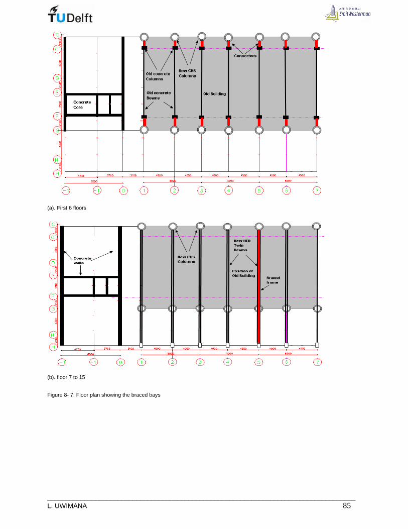
___________________________________________________________________________________ L. UWIMANA 85
(a). First 6 floors
(b). floor 7 to 15
Figure 8- 7: Floor plan showing the braced bays
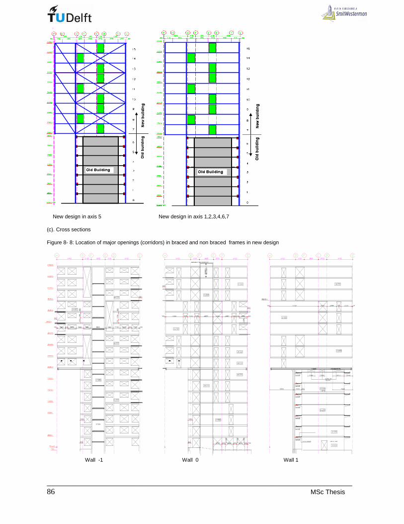
_____________________________________________________________________________ 86 MSc Thesis
New design in axis 5 New design in axis 1,2,3,4,6,7 (c). Cross sections Figure 8- 8: Location of major openings (corridors) in braced and non braced frames in new design
Wall -1 Wall 0 Wall 1
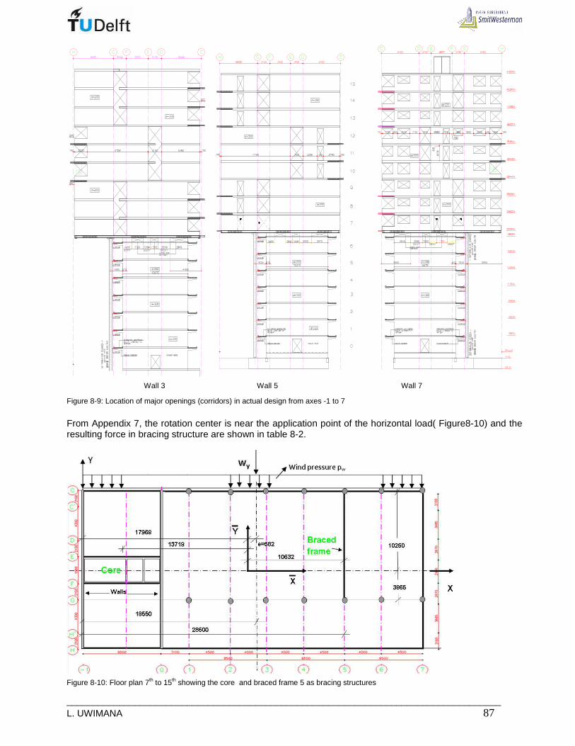
___________________________________________________________________________________ L. UWIMANA 87
Wall 3 Wall 5 Wall 7
Figure 8-9: Location of major openings (corridors) in actual design from axes -1 to 7
From Appendix 7, the rotation center is near the application point of the horizontal load( Figure8-10) and the resulting force in bracing structure are shown in table 8-2.
Figure 8-10: Floor plan 7th to 15th showing the core and braced frame 5 as bracing structures
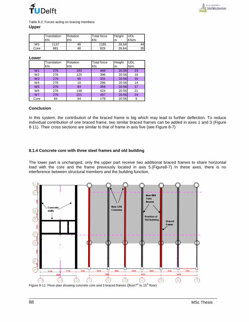
_____________________________________________________________________________ 88 MSc Thesis
Table 8-2: Forces acting on bracing members
Upper
Translation Rotation Total force Height UDLKN KN KN m KN/m
W5 1137 48 1185 26,64 44Core 881 48 929 26,64 35
Lower
Translation Rotation Total force Height UDLKN KN KN m N/m
W1 276 193 469 20.56 23W2 276 120 396 20.56 19W3 276 55 331 20.56 16W4 276 10 286 20.56 14W5 276 83 359 20.56 17W6 276 148 424 20.56 21W7 276 221 497 20.56 24
Core 84 94 178 20.56 9 Conclusion In this system, the contribution of the braced frame is big which may lead to further deflection. To reduce individual contribution of one braced frame, two similar braced frames can be added in axes 1 and 3 (Figure 8-11). Their cross sections are similar to that of frame in axis five (see Figure 8-7)
8.1.4 Concrete core with three steel frames and old building
The lower part is unchanged, only the upper part receive two additional braced frames to share horizontal load with the core and the frame previously located in axis 5.(Figure8-7) In these axes, there is no interference between structural members and the building function.
Figure 8-11: Floor plan showing concrete core and 3 braced frames (floor7th to 15th floor)

___________________________________________________________________________________ L. UWIMANA 89
From Appendix 7, one can see that the eccentricity is small (Figure8-11)and an other advantage is the reduction in forces applied to these bracing structures(table8-3)
Figure 8-11: Floor plan 7th to 15th showing the core and 3-braced frames as bracing structures
Table 8-3: Total forces acting on bracing members
Upper part
Translation Rotation Total force Height UDLKN KN KN m N/m
W1 535 60 595 26,64 22W3 535 37 572 26,64 21W5 535 135 670 26,64 25
Core 414 112 526 26,64 20
Lower part
The characteristics of the lower part is the same as what obtained in previous option (see A7.4)
Translation Rotation Total force Height UDLKN KN KN m N/m
W1 276 193 469 20.56 23W2 276 120 396 20.56 19W3 276 55 331 20.56 16W4 276 10 286 20.56 14W5 276 83 359 20.56 17W6 276 148 424 20.56 21W7 276 221 497 20.56 24
Core 84 94 178 20.56 9 The calculations shown in Appendix 7 and 8, show that the deflections reduce very much in such a way that the deflection of the core is 3 mm, whereas the steel frame deflect by 39 mm.
8.1.5 Conclusion
Concrete core alone cannot satisfy the limitation of horizontal deflection. The good results are abstained when it works together with old building and 3-braced frames. This structure will be used in further design.

_____________________________________________________________________________ 90 MSc Thesis
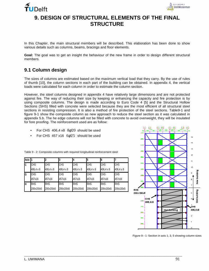
___________________________________________________________________________________ L. UWIMANA 91
9. DESIGN OF STRUCTURAL ELEMENTS OF THE FINAL STRUCTURE
In this Chapter, the main structural members will be described. This elaboration has been done to show various details such as columns, beams, bracings and floor elements. Goal: The goal was to get an insight the behaviour of the new frame in order to design different structural members.
9.1 Column design
The sizes of columns are estimated based on the maximum vertical load that they carry. By the use of rules of thumb [10], the column sections in each part of the building can be obtained. In appendix 4, the vertical loads were calculated for each column in order to estimate the column section. However, the steel columns designed in appendix 4 have relatively large dimensions and are not protected against fire. The way of reducing their size by keeping or enhancing the capacity and fire protection is by using composite columns. The design is made according to Euro Code 4 [5] and the Structural Hollow Sections (SHS) filled with concrete were selected because they are the most efficient of all structural steel sections in resisting compression. It is also a method of fire protection of the steel sections. Table9-1 and figure 9-1 show the composite column as new approach to reduce the steel section as it was calculated in appendix 5.b. The he edge columns will not be filled with concrete to avoid overweight, they will be insulated for fore proofing. The reinforcement used are as follow:
• For CHS 406,4 x8 8 20φ should be used
• For CHS 457 x16 6 25φ should be used Table 9 - 2: Composite columns with required longitudinal reinforcement steel Axis 1 2 3 4 5 6 7
CHS CHS CHS CHS CHS CHS CHS
406,4 x 8 406,4 x 8 406,4 x 8 406,4 x 8 406,4 x 8 406,4 x 8 406,4 x 8
CHS CHS CHS CHS CHS CHS CHS
457x16 457x16 457x16 457x16 457x16 457x16 457x16
RHS RHS RHS RHS RHS RHS RHS
200x150x5 200x150x5 200x150x5 200x150x5 200x150x5 200x150x5 200x150x5
C
G
H
Figure 9 - 1: Section in axis 1, 3, 5 showing column sizes
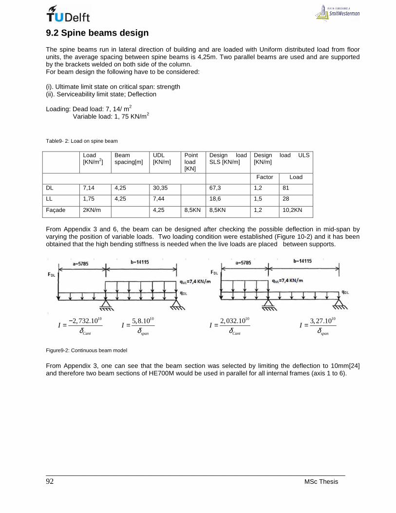
_____________________________________________________________________________ 92 MSc Thesis
9.2 Spine beams design
The spine beams run in lateral direction of building and are loaded with Uniform distributed load from floor units, the average spacing between spine beams is 4,25m. Two parallel beams are used and are supported by the brackets welded on both side of the column. For beam design the following have to be considered: (i). Ultimate limit state on critical span: strength (ii). Serviceability limit state; Deflection Loading: Dead load: 7, 14/ m2 Variable load: 1, 75 KN/m2
Table9- 2: Load on spine beam Load
[KN/m2] Beam spacing[m]
UDL [KN/m]
Point load [KN]
Design load SLS [KN/m]
Design load ULS [KN/m]
Factor Load
DL 7,14 4,25 30,35 67,3 1,2 81
LL 1,75 4,25 7,44 18,6 1,5 28
Façade 2KN/m 4,25 8,5KN 8,5KN 1,2 10,2KN
From Appendix 3 and 6, the beam can be designed after checking the possible deflection in mid-span by varying the position of variable loads. Two loading condition were established (Figure 10-2) and it has been obtained that the high bending stiffness is needed when the live loads are placed between supports.
102,732.10
Cant
Iδ
−= 105,8.10
span
Iδ
= 102,032.10
Cant
Iδ
= 103,27.10
span
Iδ
=
Figure9-2: Continuous beam model
From Appendix 3, one can see that the beam section was selected by limiting the deflection to 10mm[24] and therefore two beam sections of HE700M would be used in parallel for all internal frames (axis 1 to 6).

___________________________________________________________________________________ L. UWIMANA 93
9.3 Bracing design
Along the old building, from axis 1 to 7, the new building is supported by tall columns of about 21m high from the ground level (Figure 10-1). It results in relative slenderness relλ of 3,7 whilst the limit given by the EC4 is
2; this leads to instability of those tall columns. To enhance the stability or reducing the columns buckling length of the newly added stories, the columns should be connected to the frame of the existing building at every floor level [12]. The connectors of columns to the old building as well as cross bracing in upper floors are dimensioned according to the shear force caused by lateral loads. From Appendix 8, it has bees selected to use two channel section UPN 220x80 on both side of concrete beam of old building. These channels are connected to the new column's brackets by bolts. The in- fill inside the frame of the existing building has a big lateral stiffness and can be used to carry lateral loads and to reduce the buckling length of columns. Therefore, In lateral direction up to the 7th floor (from axis 1 to 7), the steel frames of the new structure can be stabilized by the old building (Figure 9-2). The in-fill will be modeled as single bracing in each floor level (Figure 9-3) with its equivalent area equal to
1.
10d dA L t= [6]. During calculation, an equivalent concrete section of 650 x 336 mm was used.
Where Ad is area, Ld is the diagonal length and t is wall thickness. In braced frames, from 7th to 15th floor the in made by HE400B as it was calculated in Appendix 8. In order to reduce the cantilever deflection of the beams in the frame restraining lateral loads, the cantilevers part should be braced by 3-strorey bracings of HE200B.(Figure 9-3).
(a). Lateral section in axis1,3, 5 (b) Lateral section in axis 2,4,6 and 7 Figure 9- 3: Lateral Connection of supporting columns to the existing building (frames in axes 1 to 7)

_____________________________________________________________________________ 94 MSc Thesis
9.4 Important connections
9.4.1 Connection of columns to the old building
This is the major connection since it determines the stability of the new building. The columns are connected to the old building by using twin UPN 220x80 profiles bolted on both sides of the cantilever beam carrying the balcony(of the old building) to the column of the new structure( Figure9-4).
(a). Section in Axis 1,2,3,4,5,6 and 7
(b) Plan from 1st to 6th floor Figure 9- 4: Bracing the new structure by using old building from 1st to 6th floor
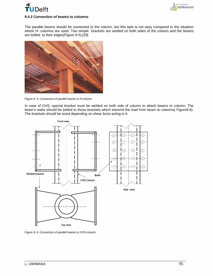
___________________________________________________________________________________ L. UWIMANA 95
9.4.2 Connection of beams to columns
The parallel beams should be connected to the column, but this task is not easy compared to the situation where H- columns are used. Two simple brackets are welded on both sides of the column and the beams are bolted to their edges(Figure 9-5).[29]
Figure 9- 5: Connection of parallel beams to H-column. In case of CHS, special bracket must be welded on both side of column to attach beams to column. The beam’s webs should be bolted to those brackets which transmit the load from beam to columns( Figure9-6). The brackets should be sized depending on shear force acting in it.
. Figure 9- 6: Connection of parallel beams to CHS-column.
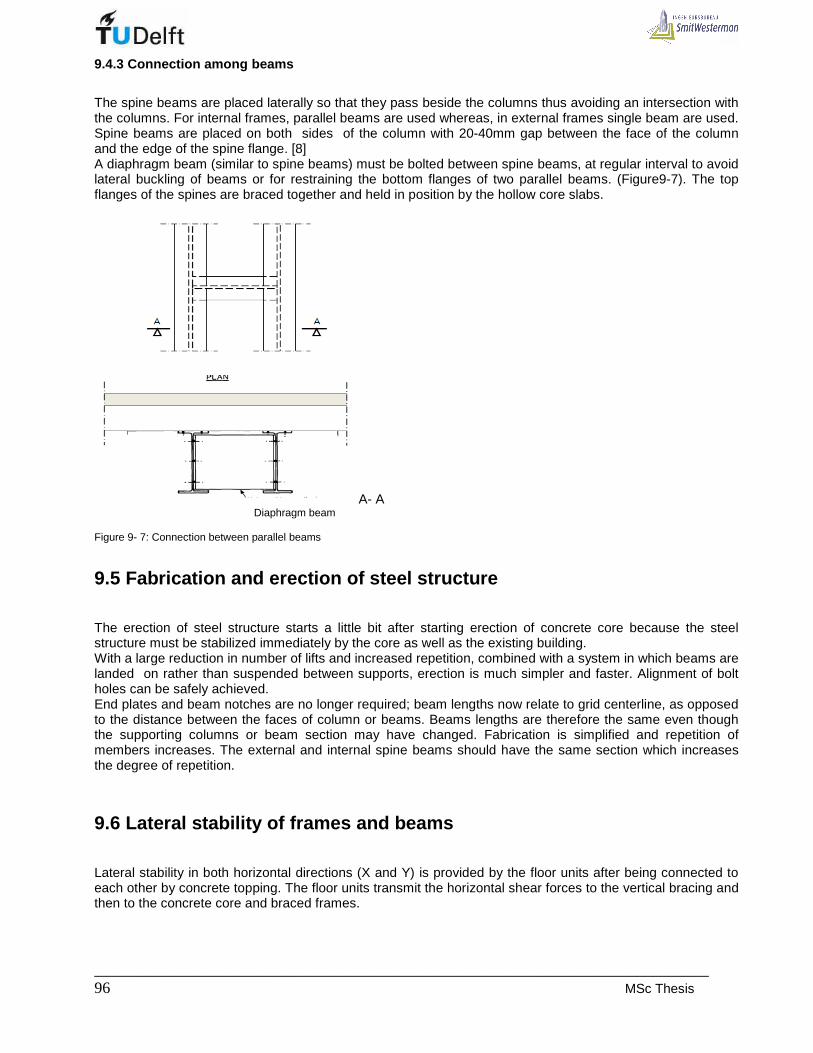
_____________________________________________________________________________ 96 MSc Thesis
9.4.3 Connection among beams
The spine beams are placed laterally so that they pass beside the columns thus avoiding an intersection with the columns. For internal frames, parallel beams are used whereas, in external frames single beam are used. Spine beams are placed on both sides of the column with 20-40mm gap between the face of the column and the edge of the spine flange. [8] A diaphragm beam (similar to spine beams) must be bolted between spine beams, at regular interval to avoid lateral buckling of beams or for restraining the bottom flanges of two parallel beams. (Figure9-7). The top flanges of the spines are braced together and held in position by the hollow core slabs.
A- A Diaphragm beam Figure 9- 7: Connection between parallel beams
9.5 Fabrication and erection of steel structure
The erection of steel structure starts a little bit after starting erection of concrete core because the steel structure must be stabilized immediately by the core as well as the existing building. With a large reduction in number of lifts and increased repetition, combined with a system in which beams are landed on rather than suspended between supports, erection is much simpler and faster. Alignment of bolt holes can be safely achieved. End plates and beam notches are no longer required; beam lengths now relate to grid centerline, as opposed to the distance between the faces of column or beams. Beams lengths are therefore the same even though the supporting columns or beam section may have changed. Fabrication is simplified and repetition of members increases. The external and internal spine beams should have the same section which increases the degree of repetition.
9.6 Lateral stability of frames and beams
Lateral stability in both horizontal directions (X and Y) is provided by the floor units after being connected to each other by concrete topping. The floor units transmit the horizontal shear forces to the vertical bracing and then to the concrete core and braced frames.

___________________________________________________________________________________ L. UWIMANA 97
10. PRELIMINARY ANALYSIS OF THE FINAL STRUCTURE
10.1 Braced steel frame
10.1.1 First order deflection
By increasing the height of building, the overall stiffness reduces and consequently the structure becomes subjected to instability. Checking on the effect of this reduction in stability is more important as far as this project is concerned. In considering the stability, the structure is considered as whole and individual members that make up the building must be examined. However, the stability of individual members will not be covered in this project since it is provided by national design code requirement. This discussion on stability looks after the whole structure rather than individual members. In its overall behavior, a multistory building resembles a cantilever column of moderate slenderness ratio. It differs from normal structural column, which is flexural element by including the possibility of dominant shear flexibility. Consequently, the potential modes of overall buckling include flexural mode but alternatively, a shear mode or possibly, a combination of these two modes (Figure 10-1).
(a) Flexural buckling (b) Shear buckling (c) Combined shear-flexural buckling Figure 10-1: Buckling modes of whole structure These mode shapes may not occur not only in transverse buckling of the structure but also in torsional or transverse-torsional forms of buckling. The frame in axis 5 was selected for calculation because its upper portion receives more horizontal loads compared to the other frame. The results for this frame will predict the behavior of other frames. (i). Flexural component The procedure for obtaining the flexural component of drift is to first calculate for the structure the external moment diagram. Then to calculate for the different vertical regions of the bent, the second moment of area I of the column sectional areas about their common centroid.
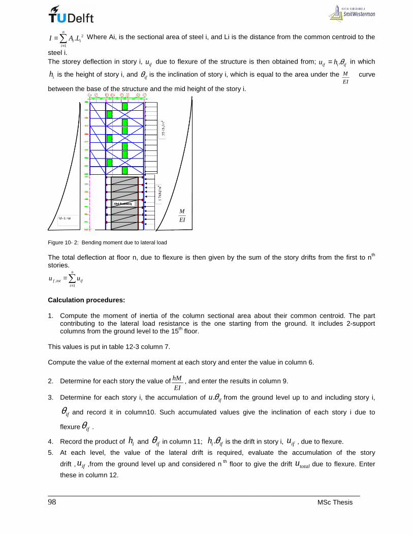
_____________________________________________________________________________ 98 MSc Thesis
2
1
.n
i ii
I A L=
=∑ Where Ai, is the sectional area of steel i, and Li is the distance from the common centroid to the
steel i. The storey deflection in story i, ifu due to flexure of the structure is then obtained from; .if i ifu h θ= in which
ih is the height of story i, and ifθ is the inclination of story i, which is equal to the area under the M
EI curve
between the base of the structure and the mid height of the story i.
Figure 10- 2: Bending moment due to lateral load The total deflection at floor n, due to flexure is then given by the sum of the story drifts from the first to nth stories.
,1
n
f tot ifi
u u=
=∑
Calculation procedures: 1. Compute the moment of inertia of the column sectional area about their common centroid. The part
contributing to the lateral load resistance is the one starting from the ground. It includes 2-support columns from the ground level to the 15th floor.
This values is put in table 12-3 column 7. Compute the value of the external moment at each story and enter the value in column 6.
2. Determine for each story the value of hM
EI, and enter the results in column 9.
3. Determine for each story i, the accumulation of . ifu θ from the ground level up to and including story i,
ifθ and record it in column10. Such accumulated values give the inclination of each story i due to
flexure ifθ .
4. Record the product of ih and ifθ in column 11; .i ifh θ is the drift in story i, ifu , due to flexure.
5. At each level, the value of the lateral drift is required, evaluate the accumulation of the story
drift , ifu ,from the ground level up and considered n th floor to give the drift totalu due to flexure. Enter
these in column 12.
M
EI

___________________________________________________________________________________ L. UWIMANA 99
Table10- 1: Evaluation of flexural component for the braced frame in axis 5(See Appendix 8)
Storey Cumul.storeyStory Story Cum.height Lateral External Frame Mod. Elast. Inclination inclinastion storey Cumul.
heigh Ground -roof load moment inertia E δθi=h*M/EI θif drift Drift
mm m KN/m Nm x1012mm 4 x10⁴N/mm 2rads Rads mm mm
Roof 2960 47200 25 0 16 21 0 6,14E-05 0,18 2,0015 2960 44240 25 1,1E+08 16 21 9,648E-08 6,14E-05 0,18 1,8214 2960 41280 25 4,4E+08 16 21 3,859E-07 6,13E-05 0,18 1,6413 2960 38320 25 9,9E+08 16 21 8,683E-07 6,09E-05 0,18 1,4612 2960 35360 25 1,8E+09 16 21 1,544E-06 6,01E-05 0,18 1,2811 2960 32400 25 2,7E+09 16 21 2,412E-06 5,85E-05 0,17 1,1010 2960 29440 25 3,9E+09 16 21 3,473E-06 5,61E-05 0,17 0,93
9 2960 26480 25 5,4E+09 16 21 4,728E-06 5,27E-05 0,16 0,768 2960 23520 25 7E+09 16 21 6,175E-06 4,79E-05 0,14 0,607 2960 20560 25 8,9E+09 16 21 7,815E-06 4,17E-05 0,12 0,46
Roof 6 2800 19600 27600 0 17 9,5E+09 41 22,5 2,887E-06 3,39E-05 0,00 0,346 2800 16800 30400 2800 17 1,1E+10 41 22,5 3,473E-06 3,10E-05 0,09 0,345 2800 14000 33200 5600 17 1,4E+10 41 22,5 4,1E-06 2,76E-05 0,08 0,254 2800 11200 36000 8400 17 1,6E+10 41 22,5 4,767E-06 2,35E-05 0,07 0,173 2800 8400 38800 11200 17 1,8E+10 41 22,5 5,474E-06 1,87E-05 0,05 0,112 2800 5600 41600 14000 17 2,1E+10 41 22,5 6,222E-06 1,32E-05 0,04 0,061 2800 2800 44400 16800 17 2,3E+10 41 22,5 7,011E-06 7,01E-06 0,02 0,02
Ground 0 47200 19600 17 2,6E+10 41 22,5 0 0,00E+00 0,00 0,00floor
Cum. height roof-ground
m
0
26640
14800177602072023680
296059208880
11840
, ,1
2n
f tot f ii
u u mm=
= =∑
(ii). Shear component
The shear component of the story drift is story i, isu is a function of the external shear and the properties of
braces and girder in that story [6]. The shear component of the total drift at floor level n, ,s totalu is equal to
the sum of the story shear component of the drift from the ground to nth stories, that is
,1
n
s tot isi
u u=
=∑
Figure 10- 3: Steel frame and lateral loads The upper part of the frame is braced by cross bracings whereas the lower part is braced by the existing building whereby the bracings are modelled as single bracings representing the masonry in-fill. [6] The corresponding horizontal drifts at each floor level displace are given by the following relations:

_____________________________________________________________________________ 100 MSc Thesis
• For cross bracing: 3
7 15 22 .BR
B BR
LQu
E L A−
=
• For single bracing: 3
0 7 2.BR B
B BR B
L LQu
E L A A−
= +
LBR and ABR are respectively is the length and the area of the bracing L is the length of girder E is modulus of elasticity. Q: The shear force LB and AB are respectively is the length and the area of the upper beam By using the above formulae, the total deflection of the building as a result of shear can be calculated in form of table. (See Table 10-2) Table10-2: Shear component of deflection for the braced frame in axis 5 ( See Appendix 8) Story Lateral Cumul.height Shear L BR LB Ad A B IB EBR Storey drift(mm) Cumulat.
load Ground -roof Q Drift
KN/m mm KN mm mm mm 2 mm 2 mm 4 N/mm 2 mm
Roof 25 0 0 16676 14115 19800 76600 2,73E+09 210000 0,00 20,51
15 25 2,96 74 16676 14115 19800 76600 2,73E+09 210000 0,21 20,51
14 25 5,92 148 16676 14115 19800 76600 2,73E+09 210000 0,41 20,30
13 25 8,88 222 16676 14115 19800 76600 2,73E+09 210000 0,62 19,89
12 25 11,84 296 16676 14115 19800 76600 2,73E+09 210000 0,83 19,27
11 25 14,8 370 16676 14115 19800 76600 2,73E+09 210000 1,04 18,44
10 25 17,76 444 16676 14115 19800 76600 2,73E+09 210000 1,24 17,40
9 25 20,72 518 16676 14115 19800 76600 2,73E+09 210000 1,45 16,16
8 25 23,68 592 16676 14115 19800 76600 2,73E+09 210000 1,66 14,71
7 25 26,64 666 16676 14115 19800 76600 2,73E+09 210000 1,86 13,05
Roof 6 17 27,6 1135,2 10385 10000 218400 52500 2,73E+08 225000 1,22 11,19
6 17 30,4 1182,8 10385 10000 218400 52500 2,73E+08 225000 1,27 9,97
5 17 33,2 1230,4 10385 10000 218400 52500 2,73E+08 225000 1,32 8,70
4 17 36 1278 10385 10000 218400 52500 2,73E+08 225000 1,37 7,38
3 17 38,8 1325,6 10385 10000 218400 52500 2,73E+08 225000 1,42 6,00
2 17 41,6 1373,2 10385 10000 218400 52500 2,73E+08 225000 1,48 4,58
1 17 44,4 1420,8 10385 10000 218400 52500 2,73E+08 225000 1,53 3,10
Ground 17 47,2 1468,4 10385 10000 218400 52500 2,73E+08 225000 1,58 1,58
3
22id
Q d
E L Aδ
=
3
2id g
Q d L
E L A Aδ
= +
, ,1
20,5n
s tot s ii
u u mm=
= =∑
Finally, the total deflection of the braced frame is the sum of deflection due to shear and that of flexure.
;1 , , 2 20,5 22,5tot st f tot s totu u u mm= + ⇒ + =
10.1. 2 Second order effect of gravity loading
The total gravity load of the building is small portion of the load that would be required to cause overall buckling. Therefore, the possibility of collapse in this way is little. The more serious stability consideration concerns the second order effects of gravity loading acting on transverse displacements caused by horizontal loading, or acting on initial vertical misalignment in the structure. The vertical eccentricity of gravity load and the presence of cantilever causes increase in transverse displacements and in member moments.
• Overall buckling analysis of frame Determination of overall buckling is necessary due to the flowing reasons: - It indicates an upper bound for the critical gravity load,
- It allows an assessment of relative vulnerability of the building to transverse buckling or tortional buckling,

___________________________________________________________________________________ L. UWIMANA 101
− It may be used in a structure for which an approximate P-Delta analysis is appropriate to evaluate an amplification factor for the displacements and moments.
• The P-Delta effect A first –order computer analysis of a building structure for simultaneous application of gravity and horizontal loads results in deflections and forces that are a direct superposition of the results for the two types of loading considered separately [6]. The interaction between the effect of gravity loading and horizontal loading is not determined by the analysis. When horizontal load acts on a building and causes it to drift, the resulting eccentricity of the gravity load from the exes of the walls (Bents) and columns produces additional external moments to which the structure responds by drifting further. The additional drift induces additional internal moments sufficient to equilibrate the gravity load moment. This effect of gravity load “P” acting on already displaced frame is called P-Delta effect.
• Buckling force
Mostly, all stabilizing systems can be schematized as a flexural cantilever. The buckling length 0L of a fully
restrained flexural cantilever of height L and constant stiffness EI , depends on the origin of forces.(Figure 10-4). As the number of floor is more than 5, the buckling length 0 1,12L L=
The buckling force 1
2
20
E
EIP
L
π=
Figure 10-4: Buckling load for stabilizing structure which are fully restrained [ 14] In reality the stabilizing elements are always partly restrained, the degree of fixity depends on the stiffness of foundation. This degree of fixity is expressed by the spring constant C. The buckling force 2EP of a partly
restrained cantilever EI is given by : 2E
CP
L= . As the frame is more than 5 stories,
2 0,5E
CP
L=
Figure 10-5: Buckling load for stabilizing structures which are partly restrained [14]
The total buckling force of partly restrained stabilizing element EP is determined as follows:

_____________________________________________________________________________ 102 MSc Thesis
1 2
1 1 1
E E EP P P= +
• Amplification factor A vertical cantilever displaced laterally by a uniform distributed horizontal load is subjected to the increase of horizontal displacement when a concentrated vertical load is placed at free end of the cantilever [14] (Figure10-6). The rate at which the horizontal displacement increases is known as amplification factor.
Figure 10-6: Second order effect for partly restrained bracing structure [14]
If initial deflection of the top of a column is 1stu , then the deflection due to the second order 2ndu is as follow:
1 1 12 2 12 3
1...
1st st st
nd nd st
u u uu u u
n n n n= + + + ⇒ =
−,
The buckling force is reached when n=1 and the first term 11
stst
uu
n= and the total added deflection becomes
infinitely large. Therefore EE
PP n P n
Pγ
γ= ⇒ =
- The first order deflection 3
1 3st
HLu
EI=
- The second order deflection 2 1
1
1nd stu un
=−
- Total deflection 1 1 1 1
1
1 1tot st st tot st st
nu u u u u u
n n= + ⇒ =
− −
The total moment1 .
1t st
nM HL u P
n= +
−, then 1.E stHL P u= ; hence
1t
nM HL
n=
−
• Calculation results
The calculations in Appendix9 show that EPn
Pγ= , 115n = . The amplification factor 1,01
1
n
n=
−; this shows that
the second degree effect is small.

___________________________________________________________________________________ L. UWIMANA 103
The second degree deflection: 2 1
1
1nd stu un
=−
, 2
122,5 0,20
115 1ndu mm= =−
10.1.3 Effect of foundation rotation
A flexible foundation will affect the overall stability of a building by reducing the effective lateral stiffness of the vertical cantilevers structure. It increases the deflection from horizontal load and hence increases the second order effect. The horizontal deflection of flexural cantilever subjected to uniform distributed load is given by this relation.
3
1 8st
wLu
EI= [14]
If the foundation rotational flexibility is defined as the rotation per unit moment is C, then the deflection is increased to:
3 2
8 2rot
wL wLu
EI C= + [14]
• Determination of spring constant C for pile foundat ion
Constant C depends on elastic deformation of pile and moment distribution on pile group. Each pile in group receives a load nP generated by the moment
.np
MP e
I=
Elastic deformation of a pile is as follow:
.
.1,5n p
p p
P LL
E A∆ =
Where : pI = the second moment of area of the pile group
e = distance of individual pile from centroidal axis of the pile group
pL =Length of the pile
pE = Modulus of elasticity of the pile
pA = Cross section area of the pile
1,5= factor covering the deformation of pile foot
Then the rotation angle L
eϕ ∆= and
MC
ϕ=
• Calculation results
The calculations done in Appendix 9 , show the total moment in foundation due to lateral load and eccentricity is 50765KNm and the spring constant of piles is 6208.10 /KNm rad . Therefore, the deflection due to foundation rotation becomes negligible since it is given by this formula:
rot
Mu
C= .
Figure 10-7: Pile foundation [14]

_____________________________________________________________________________ 104 MSc Thesis
10.1.4 Effect of moment due to cantilevers
As the new structure has the big cantilevers, these make the new building to be eccentrically placed with respect to the supporting elements. Therefore further horizontal deformations will occur.
(a) Stabilizing frame (b) Stabilizing frame schematized as Vertical cantilever Figure 10-8: Stabilizing frame showing moment loading from cantilevers
The deformation Mδ of cantilever loaded with a bending moment is given by this formula: 2
2i i
M
M Lu
EI= ∑ , where iM is the bending moment in cantilever level i and iL is the height from foundation
to the cantilever level i . The results from Appendix 9 , show that the frame can drift horizontally by 2mm
10.1.5 Conclusion
The procedures stated above were meant to check any kind of failure that can occur in the new structure. The final horizontal drift is the summation of the drifts caused by:
• First order deflection ( 1stu )
• Second order deflection ( 2ndu )
• Deflection due to the rotation of foundation ( rotu )
• Deflection due to moments in cantilevers ( Mu )
1 2Total st nd rot Mu u u u u= + + +
All these deflection components were calculated in Appendix 9 and it has been obtained that the total deflection of the braced frame 22,5 0,2 0 2 24,7Totalu mm= + + + =
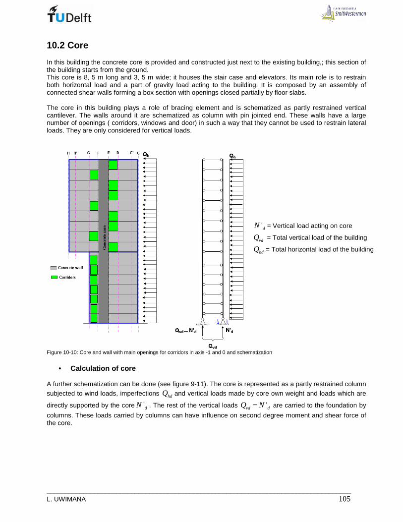
___________________________________________________________________________________ L. UWIMANA 105
10.2 Core
In this building the concrete core is provided and constructed just next to the existing building,; this section of the building starts from the ground. This core is 8, 5 m long and 3, 5 m wide; it houses the stair case and elevators. Its main role is to restrain both horizontal load and a part of gravity load acting to the building. It is composed by an assembly of connected shear walls forming a box section with openings closed partially by floor slabs. The core in this building plays a role of bracing element and is schematized as partly restrained vertical cantilever. The walls around it are schematized as column with pin jointed end. These walls have a large number of openings ( corridors, windows and door) in such a way that they cannot be used to restrain lateral loads. They are only considered for vertical loads.
Figure 10-10: Core and wall with main openings for corridors in axis -1 and 0 and schematization
• Calculation of core
A further schematization can be done (see figure 9-11). The core is represented as a partly restrained column subjected to wind loads, imperfections hdQ and vertical loads made by core own weight and loads which are
directly supported by the core 'dN . The rest of the vertical loads 'vd dQ N− are carried to the foundation by
columns. These loads carried by columns can have influence on second degree moment and shear force of the core.
'dN = Vertical load acting on core
vdQ = Total vertical load of the building
hdQ = Total horizontal load of the building

_____________________________________________________________________________ 106 MSc Thesis
Figure10-11: Schematization of core and supporting wall [14] The partly restrained core is subjected to horizontal force hdQ and normal force 'dN . The
walls( represented as one column hinged at the top and base are attached to the core by floor slab and are loaded with 'vd dQ N− .
By horizontal force, the displacement of the whole system is tanL α .
By the angular rotationα , a tensile force ( )' tanvd dT Q N α= − occurs.
At the base of the restrained core the second-degree moment ;2core ndM is:
( );2 ;1 . ' tancore nd vd dM T L Q Nα α= ⇒ −
The normal force 'dN causes:
;2 ;2 ' tancore nd dM N L α=
Therefore the total second-degree moment is ;2 tancore nd vdM Q L α=
• Determination of the horizontal deflection of the c ore. In Appendix 9, the calculations were done in the same way as for the braced frame. One can see that the total deflection is mainly composed by the 1st order deflection and the effect of cantilever deformation . The second order effects as well as the foundation rotation are negligible since the foundation is so stiff. The final deflection becomes 37,1 mm, which is less than 59mm; the maximum allowable horizontal deflection as it was calculated in Appendix 7.
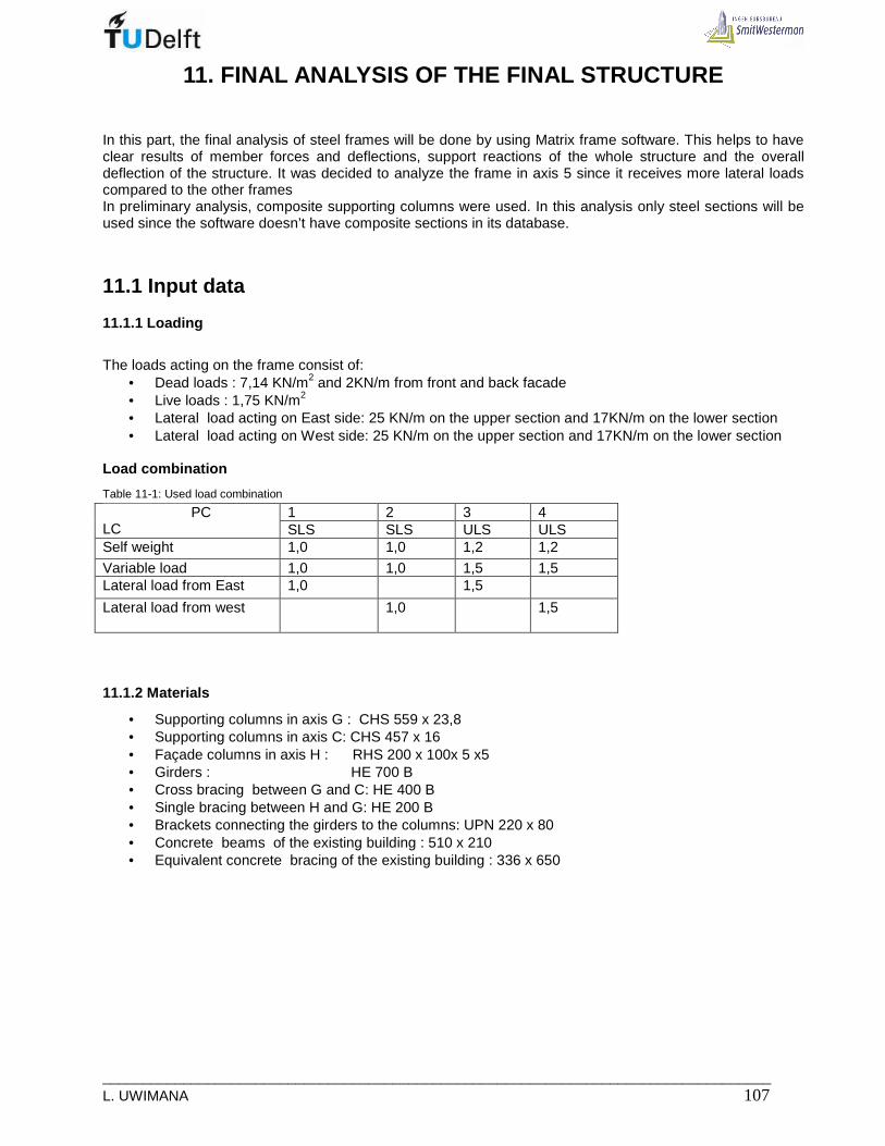
___________________________________________________________________________________ L. UWIMANA 107
11. FINAL ANALYSIS OF THE FINAL STRUCTURE
In this part, the final analysis of steel frames will be done by using Matrix frame software. This helps to have clear results of member forces and deflections, support reactions of the whole structure and the overall deflection of the structure. It was decided to analyze the frame in axis 5 since it receives more lateral loads compared to the other frames In preliminary analysis, composite supporting columns were used. In this analysis only steel sections will be used since the software doesn’t have composite sections in its database.
11.1 Input data
11.1.1 Loading
The loads acting on the frame consist of:
• Dead loads : 7,14 KN/m2 and 2KN/m from front and back facade • Live loads : 1,75 KN/m2 • Lateral load acting on East side: 25 KN/m on the upper section and 17KN/m on the lower section • Lateral load acting on West side: 25 KN/m on the upper section and 17KN/m on the lower section
Load combination
Table 11-1: Used load combination
1 2 3 4 PC LC SLS SLS ULS ULS Self weight 1,0 1,0 1,2 1,2
Variable load 1,0 1,0 1,5 1,5 Lateral load from East 1,0 1,5
Lateral load from west
1,0 1,5
11.1.2 Materials
• Supporting columns in axis G : CHS 559 x 23,8 • Supporting columns in axis C: CHS 457 x 16 • Façade columns in axis H : RHS 200 x 100x 5 x5 • Girders : HE 700 B • Cross bracing between G and C: HE 400 B • Single bracing between H and G: HE 200 B • Brackets connecting the girders to the columns: UPN 220 x 80 • Concrete beams of the existing building : 510 x 210 • Equivalent concrete bracing of the existing building : 336 x 650

_____________________________________________________________________________ 108 MSc Thesis
Figure 11-1: Plan for floor 7th to 15 and section in axes 1,3 and 5 11.1.3 Spring stiffness of bracing structure The stability is provided by concrete core and braced frames; the distribution of lateral loads is based on assumption that floors( Horizontal diaphragms are infinitely stiff in their plane. Each floor is supported by stabilizing structures which are schematized as springs. (Figure 11-2).
Figure 11-2: Schematization of floor and stabilizing structures
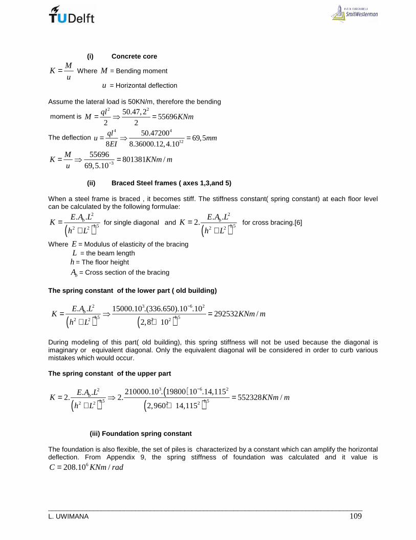
___________________________________________________________________________________ L. UWIMANA 109
(i) Concrete core M
Ku
= Where M = Bending moment
u = Horizontal deflection Assume the lateral load is 50KN/m, therefore the bending
moment is 2 250.47,2
556962 2
qlM KNm= ⇒ =
The deflection 4 4
12
50.4720069,5
8 8.36000.12,4.10
qlu mm
EI= ⇒ =
3
55696801381 /
69,5.10
MK KNm m
u −= ⇒ =
(ii) Braced Steel frames ( axes 1,3,and 5)
When a steel frame is braced , it becomes stiff. The stiffness constant( spring constant) at each floor level can be calculated by the following formulae:
( )2
1,52 2
. .bE A LK
h L=
+ for single diagonal and
( )2
1,52 2
. .2. bE A L
Kh L
=+
for cross bracing.[6]
Where E = Modulus of elasticity of the bracing L = the beam length h = The floor height
bA = Cross section of the bracing
The spring constant of the lower part ( old buildi ng)
( ) ( )
2 3 6 2
1,5 1,52 2 2 2
. . 15000.10 .(336.650).10 .10292532 /
2,8 10
bE A LK KNm m
h L
−
= ⇒ =+ +
During modeling of this part( old building), this spring stiffness will not be used because the diagonal is imaginary or equivalent diagonal. Only the equivalent diagonal will be considered in order to curb various mistakes which would occur. The spring constant of the upper part
( )( )
( )3 6 22
1,5 1,52 2 2 2
210000.10 . 19800 10 .14,115. .2. 2. 552328 /
2,960 14,115
bE A LK KNm m
h L
−
= ⇒ =+ +
(iii) Foundation spring const ant The foundation is also flexible, the set of piles is characterized by a constant which can amplify the horizontal deflection. From Appendix 9, the spring stiffness of foundation was calculated and it value is
6208.10 /C KNm rad=

_____________________________________________________________________________ 110 MSc Thesis
Figure 11-3: Calculation model of section in axes 1,3 and 5 with bracing structures replaced by srping supports at each floor leve
11.1.4 Connection between girders and edge columns
Hinge or rigid connection can be used to connect the beams to the columns. It is therefore necessary to check a method with more benefits so that it can be adopted when modeling the frame.
(i) Hinge connection

___________________________________________________________________________________ L. UWIMANA 111
Figure 11-4: Moment distribution and deflection for hinge connection
(ii) Rigid connection
Figure 11-5: Moment distribution and deflection for rigid connection
From the above moment and deflection diagrams, one can see that the moments and deflection in mid span reduce considerably when floor beams are clamped to the columns. Therefore, rigid connections would be used in modeling the frame in order to have minimum deflections

_____________________________________________________________________________ 112 MSc Thesis
11.2 Braced frame modeling and results
All the data stated above are put in Matrix frame software. It was decided to use 3-D model, because the representation of the double beam system can be easy. As the frame in axis 5 takes much of lateral loads; it was decided to use it in analysis; other frames in axes 1 and 3 will have more or less the same behavior as the frame in axis 5.
Figure 11-6: 3-D model of the frame
11.2.1 Deflection
The horizontal and vertical deflections of the frame are checked by applying service load to the frame, load combinations 1 and 2 are considered. The results (Figure 11-3) show that (load combination 1 and 2) the structure will not sway laterally due to high spring stiffness of the bracing structures. However, the maxima vertical deflection of girders and their cantilevers are respectively 27 mm and 18 mm. (Figure 11-7 and 11-8) These deflections are less than the allowable maximum deflection for girders and their cantilevers, which are respectively 56mm and 23mm.

___________________________________________________________________________________ L. UWIMANA 113
• Load case 1

_____________________________________________________________________________ 114 MSc Thesis
Figure 11-7: 3-D Model showing a deflected braced frame for load case 1
• Load case 2

___________________________________________________________________________________ L. UWIMANA 115
Figure 11-8: 3-D Model showing a deflected braced frame for load case 2
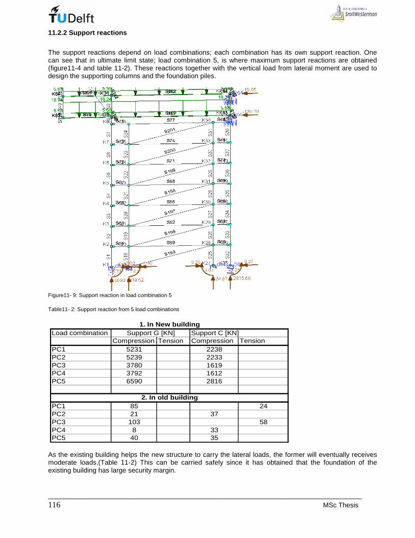
_____________________________________________________________________________ 116 MSc Thesis
11.2.2 Support reactions
The support reactions depend on load combinations; each combination has its own support reaction. One can see that in ultimate limit state; load combination 5, is where maximum support reactions are obtained (figure11-4 and table 11-2). These reactions together with the vertical load from lateral moment are used to design the supporting columns and the foundation piles.
Figure11- 9: Support reaction in load combination 5 Table11- 2: Support reaction from 5 load combinations
Load combination Support C [KN]Compression Tension Compression Tension
PC1 5231 2238PC2 5239 2233PC3 3780 1619PC4 3792 1612PC5 6590 2816
PC1 85 24PC2 21 37PC3 103 58PC4 8 33PC5 40 35
Support G [KN]1. In New building
2. In old building
As the existing building helps the new structure to carry the lateral loads, the former will eventually receives moderate loads.(Table 11-2) This can be carried safely since it has obtained that the foundation of the existing building has large security margin.

___________________________________________________________________________________ L. UWIMANA 117
11.3 Modeling of Un-braced frame carrying only the gravity load
The frames carrying only the gravity load are those, which do not take part in resisting the lateral forces. There would not be deformation due to the lateral load. The frames taken into account are frames located in axes 2, 4, 6 and 7. The connection of the frame to the old building and to the bracing structures by the floor system will relieve the structure from swaying toward cantilever sides (Figure 11-10)
Figure 11- 10: Managing buckling and imperfection of frame taking gravity loads. As the new structure starts at 20,56m high, columns are subjected to buckling, but when they are connected to the old building at each storey, the buckling length becomes 2,8m and then , the structure is more stable. The result of this method is the deflection of beams only in vertical direction. When beams and edge columns are connected by hinges, it has been obtained that the deflection of beams is 18 mm and 38 mm for cantilever and between supports (Figure 11-11).

_____________________________________________________________________________ 118 MSc Thesis
(a) Upper floors
(b) Lower floors Figure 11- 11: Deflection of beams when there are pin connections between beams and edge columns

___________________________________________________________________________________ L. UWIMANA 119
11.4. Reduction of vertical deflection of beams
Although the horizontal deflection is negligible in models because of lateral spring stiffness of the bracings, the beams have a considerable vertical deflection in their mid-spans. The vertical deflection can be minimized welding small cantilevers to the columns and then connecting them to the beams.( Figure11-12)
Figure11- 12: Braced and non-braced frames with welded cantilevers to reduce the vertical deflection of beams The results from computer model show that the maximum vertical deflection of beams has reduced from 28 to 20 mm for middle fields and from 18 to 15 mm for cantilevers. These cantilever are supposed to be welded on sides of columns where the beams meet columns; parallel struts would be used.( See figure 11-13)

_____________________________________________________________________________ 120 MSc Thesis
Figure11- 13: Frame model with cantilevers to reduce vertical deflection of beams However, in braced frames, these struts, will be crossing with the bracings and aesthetically unpleasant. Therefore another means of bracing can be suggested even though its behavior will not be covered in this report(See figure11-14).
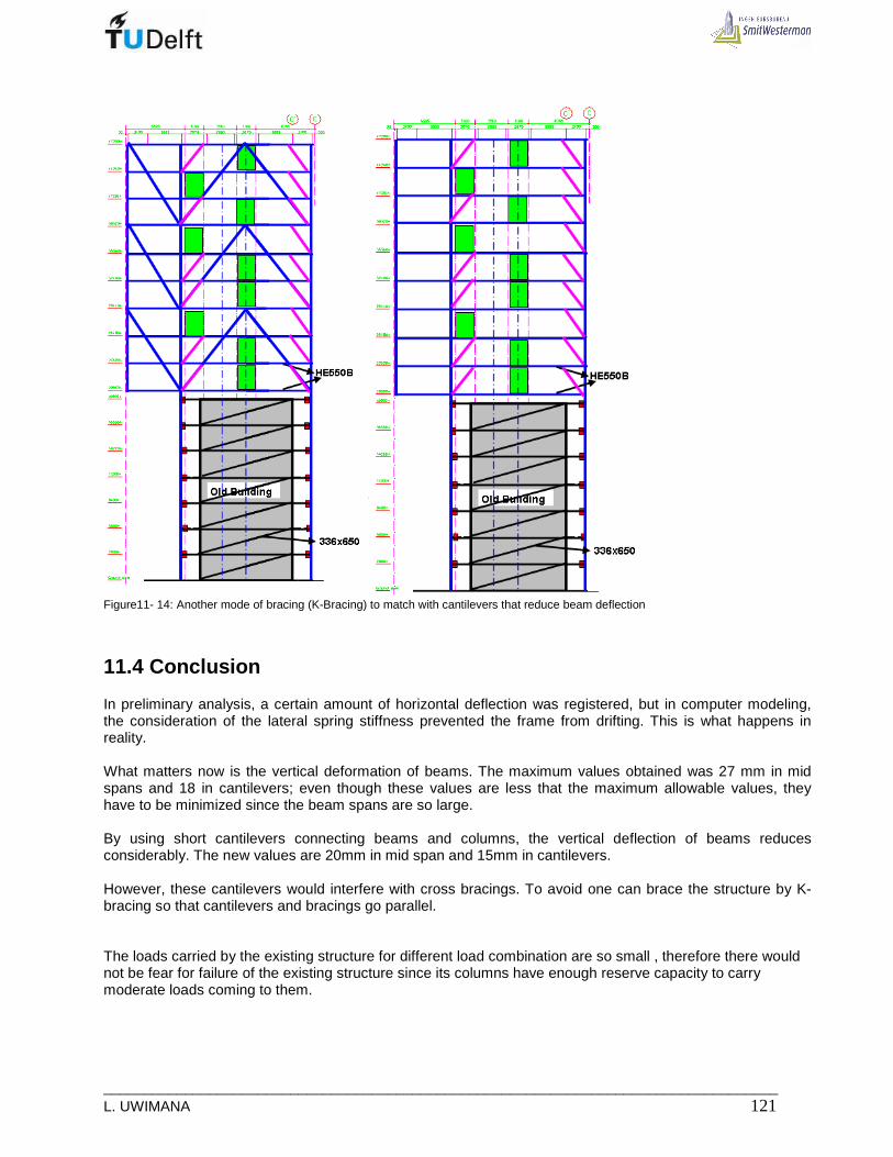
___________________________________________________________________________________ L. UWIMANA 121
Figure11- 14: Another mode of bracing (K-Bracing) to match with cantilevers that reduce beam deflection
11.4 Conclusion
In preliminary analysis, a certain amount of horizontal deflection was registered, but in computer modeling, the consideration of the lateral spring stiffness prevented the frame from drifting. This is what happens in reality. What matters now is the vertical deformation of beams. The maximum values obtained was 27 mm in mid spans and 18 in cantilevers; even though these values are less that the maximum allowable values, they have to be minimized since the beam spans are so large. By using short cantilevers connecting beams and columns, the vertical deflection of beams reduces considerably. The new values are 20mm in mid span and 15mm in cantilevers. However, these cantilevers would interfere with cross bracings. To avoid one can brace the structure by K-bracing so that cantilevers and bracings go parallel. The loads carried by the existing structure for different load combination are so small , therefore there would not be fear for failure of the existing structure since its columns have enough reserve capacity to carry moderate loads coming to them.

_____________________________________________________________________________ 122 MSc Thesis
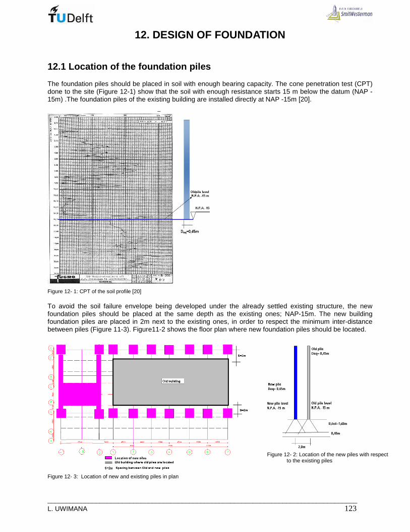
___________________________________________________________________________________ L. UWIMANA 123
12. DESIGN OF FOUNDATION
12.1 Location of the foundation piles
The foundation piles should be placed in soil with enough bearing capacity. The cone penetration test (CPT) done to the site (Figure 12-1) show that the soil with enough resistance starts 15 m below the datum (NAP -15m) .The foundation piles of the existing building are installed directly at NAP -15m [20].
Figure 12- 1: CPT of the soil profile [20] To avoid the soil failure envelope being developed under the already settled existing structure, the new foundation piles should be placed at the same depth as the existing ones; NAP-15m. The new building foundation piles are placed in 2m next to the existing ones, in order to respect the minimum inter-distance between piles (Figure 11-3). Figure11-2 shows the floor plan where new foundation piles should be located.
Figure 12- 3: Location of new and existing piles in plan
Figure 12- 2: Location of the new piles with respect
to the existing piles
_____________________________________________________________________________ 124 MSc Thesis
12.2 Choice of type of foundation
The choice of foundation method is also very important as far as this project is concerned. The new foundation is placed closer to the existing foundation. What matters is the disturbance of the already settled and stabilized foundation soil of the existing building. Without careful choice of appropriate foundation method, some damages may occur to the existing building. It is very important to choose a method, which is free from vibration, with soil displacement, instead of removing soil. Fundex piles are best alternative to construct the foundation for the new building. There are various sizes; namely 380,450 & 520 mm diameter; in this project the piles of 380mm diameter can chosen
12.3 Description of Fundex piles [29]
The Fundex pile section is cast in place reinforced concrete pile, installed by torque and down pressure, completely free of vibration and with no pile driving noise. It is a soil displacement pile over its full pile length. The method of installation permits no possibility of discontinuities of the pile shaft because a sealant prevents intrusion of soil or water into the incomplete pile. There are no limitations on the depth of the reinforcing cage or rebar size within the pile. There is no central tendon required, and concrete is not soil mixed, but rather pure structural concrete. Fundex piles are also soil displacement cast-in-place piles. While the operation appears similar to a drilling job, the Fundex tip displaces the soil laterally, bringing no spoils to the ground surface. This soil-displacement quality greatly enhances the pile's capacity over comparably sized conventional drilled shafts. A cast iron boring tip is fitted to a drilling mandrel by means of a chuck assembly. The mandrel is installed by using torque and down-pressure, producing very low noise levels and no vibration. Upon reaching the bearing layer - or upon sufficiently penetrating soil strata in the case of friction pile design - a reinforcing cage is suspended within the mandrel, and concrete is placed. The drill mandrel is then extracted by oscillation thereby leaving the tip, concrete and cage behind in place. In this way, true full section cast-in-place concrete piles are constructed.
12.3.1 Application of Fundex piles
Fundex piles are suitable for projects on which
• Drilled shafts may be appropriate, but drill spoils are to be avoided • Space restricts the use of larger diameter drilled shafts, and higher unit friction values are required to
develop capacity • The project space is too confined for conventional precast pile driving • Noise or vibration is not permissible • There is a high variability in required pile depths • Are too remote from precast pile fabricators to economically ship precast piles to the site. • Auger cast pile construction presents quality control issues
12.3.2 Advantages of Fundex piles
• Suitable for projects inaccessible to precast piles due to space restrictions • Roughened amplitude of concrete surface affords higher unit friction than smooth pipe or concrete
pile • Installation produces no pile driving noise or vibration • No danger to adjacent buildings during drilling. Soil displacement so no decrease of cone resistance
and no harm to existing piles. • The only noise comes from the power pack only.

___________________________________________________________________________________ L. UWIMANA 125
• Running sands, caving or very poor soils, or the presence of a high water table do not affect the installation of Fundex pile.
• Because Fundex piles are displacement piles, the Fundex pile affords a higher unit friction capacity than a comparable drilled shaft
• No materials are conveyed to the surface or are allowed to migrate to deeper strata- a consideration if contaminants are known to exist at a site. Drill spoil off haul is virtually eliminated.
• Fundex method allows reinforcing cages of any length, and constructs the structural shaft without necking or soil intrusion
• Fundex piles are full section soil displacement
12.4 Method of installation
The Fundex piles are constructed in four phases namely, drilling, placing reinforcement and concrete, removal of drilling tube, and finishing. (See figure 12-4)
Figure 12- 4: Installation of pile [29] Phase 1 A crawler is mounted hydraulic piling rig fitted with an hydraulic drill table with 1, 5 m stroke Hydraulic pull down. The drill point complete with a bayonet joint, is attached to a drill tube which in turn is clamped in the drill table. To commence drilling the drill table is raised to its maximum height and the drill tube is clamped. The drill tube is drilled into the ground with a pull down force on the axis and a torque. The ground is displaced, as drilling takes place. Phase 2 After ensuring that the drill tube is dry, the reinforcing is placed in position and sufficient concrete for the complete pile is poured into the drill tube. Phase 3 The drill tube is extracted with upward and downward oscillating movements. The drill-point forms an enlarged pile base and stays in the soil. Phase 4 The pile is completed when the reinforcing cage is placed in position. When the foundation level is reached, the reinforcement is placed over the anchor- cage in the pile-point, which guarantees sufficient anchor length. The drill-tube can be extracted after placing of concrete. Due to the shape of the pile-point, the Fundex piles are very suitable for tension piles.
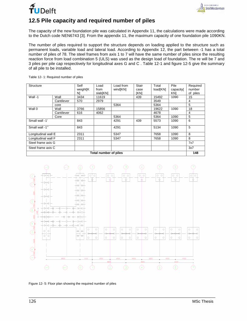
_____________________________________________________________________________ 126 MSc Thesis
12.5 Pile capacity and required number of piles
The capacity of the new foundation pile was calculated in Appendix 11, the calculations were made according to the Dutch code NEN6743 [3]. From the appendix 11, the maximum capacity of one foundation pile 1090KN. The number of piles required to support the structure depends on loading applied to the structure such as permanent loads, variable load and lateral load. According to Appendix 12, the part between -1 has a total number of piles of 78. The steel frames from axis 1 to 7 will have the same number of piles since the resulting reaction force from load combination 5 (ULS) was used as the design load of foundation. The re will be 7 and 3 piles per pile cap respectively for longitudinal axes G and C . Table 12-1 and figure 12-5 give the summary of all pile to be installed. Table 12- 1: Required number of piles Structure Self
weight[KN]
Load from slab[KN]
Load from wind[KN]
Stair case [KN]
Total load[KN]
Pile capacity[KN]
Required number of piles
Wall 3434 11619 439 15492 15 Cantilever 570 2979 3549
1090 4
Wall -1
core 5364 5364 5 Wall 3766 15856 19622 18 Cantilever 616 4062 4678
1090 4
Wall 0
Core 5364 5364 1090 5 Small wall -1’ 843 4291 439 5573 1090 6
Small wall -1’’ 843 4291 5134 1090 5
Longitudinal wall E 2311 5347 7658 1090 8 Longitudinal wall F 2311 5347 7658 1090 8 Steel frame axis G 7x7
Steel frame axis C 3x7
Total number of piles 148
Figure 12- 5: Floor plan showing the required number of piles

___________________________________________________________________________________ L. UWIMANA 127
For frames receiving the gravity load, the load is shared equally among piles. However, for the stabilizing structures the load from the lateral moment is added to the gravity load. The distribution of lateral load to the piles depends on location of piles; the edge piles receive more load than the inner piles. [24]
Figure 12- 6: Lateral load on foundation The load on pile due to lateral moment is determined by using the following formula.
.
.later
M xP
I= With 2
.
1
2 laterM q h=
X: distance from the building center to the edge pile max
2
1
. .i
i iI n A x= ∑
iA is the area of pile
n: is the number of pile Xi is distance from the building center to the ith pile
.. yxi
x y
M yM xPP
n I I= + +
Where iP : load on single pile
n : Number of piles
xM and yM : Lateral moments in X and y- directions
xI and yI : Moments of inertia in X and y- directions
x and y : Distance from the center of the building to pile I, in X and y-
directions.

_____________________________________________________________________________ 128 MSc Thesis

___________________________________________________________________________________ L. UWIMANA 129
13. CONCLUSIONS AND RECOMMENDATIONS
13.1 Conclusions
The objective of this thesis was to formulate possible design alternatives to be used when adding more stories to the existing building. In this thesis the Dillenmburgsingle project designed by SmitsWesterman design office was used as a case study. The major problem was to know if it is possible to extend a low riser existing building into multi-storey building. This thesis gave a positive answer to this question whereby additional stories were designed by separating the frames of the new structure from that of existing building but functionary integrated. The load of the additional structure was reduced by using steel structure. This was very important as far as this project is concerned because the load to be transferred in the vicinity of the existing building must be limited to avoid disturbance in the existing foundation. It was concluded that two structures (existing and new) can be laterally connected for stability reason rather than putting directly additional stories on top of the existing building. Different conclusions taken throughout this thesis will be summarised in this chapter.
13.1.1 Existing Building
• Frame .
The frame of the existing building was designed according to the applied load with safety measures but no additional future structure was planned. As the frame is stiffened by the masonry in-fill, this will attract more vertical load and columns carry less load compared to their load carrying capacity. As the two structures are connected laterally, these columns are able to handle portion of load brought by lateral loading.
• Stability : The lateral stiffness of the existing is provided by the concrete frame with masonry in-fill. It has been obtained that the structure is stiff enough since the frames are provided at every 4 and 4,5m, for this, each frame receive less lateral load. Therefore, the existing building can be used to restrain a part of the lateral load by connecting the existing beams to the columns of the new structure.
• Foundation
The foundation of the existing building is made of concrete piles 340x340mm shaft and a tip of 450x450. Each pile was driven up to the depth of 15m (NAP-15m) and loaded with maximum load of 700KN (70Tons). The estimation of the pile capacity revealed that, each pile has a maximum capacity of 1736 KN, which means that only 40% of its capacity is utilised. However, exploiting the remaining capacity becomes impossible since the superstructure cannot withstand additional loading. In addition too much load is concentrated to the cantilever side which would require additional piles which is practically impossible to do when the existing building is still standing. Unused capacity can be used to carry lateral loads to the soil. Even though some columns can erected inside the existing building, but each frame of the new building brings to the ground a load of 9407KN ( 6658 + 2749) which can be taken by 10 Fundex piles. This is quite impossible job because the foundation beams for existing building carry 5-piles; no place left for additional piles. In addition to that it is totally impossible to make additional foundation inside the existing building without demolishing it. The simplest method to make the foundation for the new building was to separate it from the existing one.

_____________________________________________________________________________ 130 MSc Thesis
13.1.2 New structure
• Structural system and construction materials
It was decided to extend the existing building form 6-stories to 15-stories by separating the new structures from the existing building. The frame of the new building is designed by bridging the existing building. Therefore, the supporting elements should be put to the sides of the existing building. This approach was also decided depending on the presence of the big cantilevers made on one side of the building. The cantilevers are 6m long, and by respecting the maximum cantilever to field ratio of 0, 42, the field span should be at least 14 m. This length can only be obtained on two balconies edges of the existing building. It is in this place, new supporting elements can be erected. The span is then long; to have a successful design, light weight materials such as steel should be used for columns and walls. It was decided to use steel frame since traditional concrete structure can be structurally less efficient for such big spans and also bringing large weight near existing foundation could induce damages. Precast floor units will also be used due to its significant reduced weight and easy erection.
• Alternatives Four alternatives were discussed, but the most efficient method to use is a system of two parallel continuous girders cantilevering at each floor level ; they are put on each side of the column. The system is much better to handle the cantilevers and provide the continuity of both columns and girders, making the simple connection and speedy erection. Around the core concrete walls can be used to provide the cantilevers because the presence of the core makes it impossible to have sufficient cantilever to span ratio. As this part is not to be put on top of the existing building, its weight doesn’t matter and cannot have effect to the existing foundation.
• Stability Different methods of stabilizing the new structure were analysed in chapter 8 and Appendix7. All cases were checked, it has been concluded that, due to high slenderness ratio of the core, the stability cannot be fulfilled once core is used alone. The only successful method is by using the core and three braced frames in axes 1, 3 and 5. The existing building also play a significant role since all frames of the new structure are laterally connected to the frame of the existing building.
• Foundation The new foundation is to be constructed near the already existing foundation. To avoid disturbance du to vibration caused by driven piling method, soil displacement method can be used. Fundex piles type (380mm shaft diameter) were selected to be used in this project; each pile with a capacity of 1090KN.
___________________________________________________________________________________ L. UWIMANA 131
13.2. Recommendations
• Shape The shape of any structure influences the force distribution in a structure. Therefore, it is important to be able to discuss shape considerations with an architect when extending an existing building. An additional building with a long cantilever is more challenging to the structural engineer. It is important when deciding to add amore story on top of the existing building to follow the shape of the existing building or by providing small cantilevers on both sides of the existing building.
• Construction materials and framing Whenever additional structure is decided to be put on existing building, light weight materials should be used. It facilitate the construction of cheap foundations and the load from the new structure would not affect the foundation of the existing structure. When deciding to add more story cantilevering the existing building, the efficient method to use continuous columns and girder. This is an easy method to make cantilevers and for big span, two beams share gravity load and take it to the columns without failure. Continuous system facilitates the erection by limiting the number of connections and therefore less horizontal drift can be achieved.
• Stability and supporting In this thesis, overall stability of the new building can be achieved by concrete core associated with three steel frames on the other side of the building. As the new structure starts at high level (20m high), the support columns are so slender. The stability should be enhanced by connecting new and existing structures at each floor level . The frame of the new structure is mainly made of two composite columns erected on the sides of the existing building.
• Foundation: Soil displacement foundation is a good method to make foundation near the existing structure. This is to avoid vibration which can create cracks in existing building when driven piles would be used. The piles should be placed on the sides of the existing building with respect to the location of the columns.
• Future study In this thesis, the main field of interest was based on structural design of a 15-storey building, existing 6-storey and additional 9-storeys. In case more and more story need to be constructed, wind pressure to the building becomes strong and the whole structure would be subjected the significant dynamic loading since it is made of light weight materials. Therefore it is recommended to make another case of tall building whereby dynamic behaviour should be analysed. The second point for future study is to analyse thermal as wells sound comfort of occupants of such particular building with light weight materials cladding. As there were no sufficient data of soil, interaction between existing and new foundation can be provided in further research. The third study can be made to determine proper means of lateral connection between new and existing structure. Shock absorber devices should be used to avoid possible damage when new structure moves towards the existing structure.


___________________________________________________________________________________ L. UWIMANA 133
REFERENCES:
• Books, Standards, Readers, Journals and Theses
[1] NEN 6702 Technical principles for building structures -TGB 1990 - Loadings and deformations,
Augustus 2007
[2] NEN 6770: TGB 1990 - Steel structures - Basic requirements and basic rules for calculation of predominantly statically loaded structures, Mei 1997
[3] NEN 6743-1Geotechnics - Calculation method for bearing capacity of pile foundation -
Compression piles, November 2006
[4] Euro code 3: "Design of Steel Structures": ENV 1993-1-1: Part 1.1: General rules and rules form buildings, CEN, 1992.
[5] Euro code 4: "Design of Composite Steel and Concrete Structures": ENV 1994-1-1: Part 1.1: General rules and rules form buildings.
[6] Coull, Alex Smith, Bryan Stafford “Tall building structures analysis and design”, New York : Wiley, 1991
[7] Hart, F., Henn, W. and Sontag, H.: "Multi-Storey Buildings in Steel, Colins, London, 1982 [8] Brett, P. and Rushton, J., Parallel beam approach - a design guide, The Steel Construction Institute,
1990. [9] Wlfgang Schueller, High-Rise building structures A Wiley – Interscience Publication 1934
[10] Dr.ir.W.J.Raven, “Rules of thumb in Timber , concrete and steel “, TU delft , July 2003
[11] Corus Panels and Profiles, Composite Floor Decks
[12] MOFFAT, I. 1987. Method of adding additional stories to an existing storied building.
Dec29, 1992. USA patent application 842,572. Feb. 3, 1987.
[13] Vink, F., “ Algemene constructieleer(relatie met staal). TU Delft; Sufaculteit der Civiel techniek,1995
[14] J.N.J.A Vamvesky, J.C. Walraven, J.P. Straman College CT4281, Building structures II, Design and understanding of precast concrete structures in buildings ”, TU Delft Subfaculteit der Civiel techniek, November 2005
[15] R. Abspoel, J.W.G. v.d.Kuilen, J.G.M. Raadschelders, T. Tom_a, J.A. den Uijl, J.N.J.A. Vambersky and J.C. Walraven.”College CT3211, Building structures I” TU Delft, faculty of Civil Engineering and Geosciences
[16] Owling, P. J., Knowles, P. R. and Owens, G. W.: "Structural Steel Design", Butterworths, London,
1988. [17] Euro code 2: "Design of Concrete Structures": ENV 1992-1-1: Part 1.1: General rules and rules
form buildings, CEN, 1992 [18] R. Abspoel Building structures 2 CT 4281 Steel Part, TU Delft, October 2006 [19] Song Feng , W. Y., Zhang Yong 2002. The technique of adding extra-floors spanning existing
building with steel structure, Beijing [20] Municipality of Leischendam Archives, “348 Galerijwoningen te Leischendam”,1968 [21] Mendoza, G.A. and Macoun, P. with Prabhu, R., Sukadri, D., Purnomo, H. and Hartanto, H.;
“Guidelines for Applying Multi-Criteria Analysis to the Assessment of Criteria and Indicators”; CIFOR Indonesia, 1999.
[22] Eduardo Breviglieri Pereira de Castro1, Leopoldo Eurico Gonçalves Bastos2, Joseph Virgone3 , “Using Multi criteria Analysis to Aid building conception” International Conference on Engineering Optimization, Rio de Janeiro, Brazil, 01 - 05 June 2008
[23] Beckett, Derrick; Alexandrou, Andrew “Introduction to Euro code 2; design of concrete structures (including seismic actions)” New York, 1997.
_____________________________________________________________________________ 134 MSc Thesis
[24] J.P.de Hollander “Hoogbouw aan de boompjes: Een Alternatievenstudie”, Graduation thesis, TU Delft, August 2000.
[25] SMITWESTERMAN 2007. Dillenburgsingel project. Gouda. [26] W. Ruiter and F. M. Sanders, “Physical Planning” pp 151-163. Faculty of CiTG, TU Delft, 1998 [27] T. Graafland “ The structural design of Rotterdam CS south hall” Graduation thesis , TU Delft , May
2008
• Internet [28] http://www.sbe.napier.ac.uk/projects/piledesign/guide/chapter1.htm [29] http://www.foundationpiledriving.com/index.cfm/p/pages.fundex-piles.htm [30] http://www.ce-ref.com/pile_cap.htm [31] http://www.vbi.nl/?pageID=100&Title=Vloeren [32] http://www.worldsteel.org/?action=galleryphoto&id=72 [33] http://www.beslistinstaal.nl/index2.html [34] http://www.vanakenarchitecten.nl/show/nl/project/3,14,3/7
[35] http://www.willems.be/en/photoalbums/kennedy-towers-eindhoven-nl#855-1400 [36] http://www.beslistinstaal.nl/project/onderwijs1.html [37] http://www.beslistinstaal.nl/highrise/pdf/hmtr.pdf [38] http://www.worldarchitecturenews.com/index.php?fuseaction=wanappln.projectview&upload_id=11
768 [39] http://www.royalhaskoning.com/en-
GB/Fields/UrbanAreasAndBuildings/StructuralDesign/Pages/RedApple.aspx

___________________________________________________________________________________ L. UWIMANA 135
APPENDICES

_____________________________________________________________________________ 136 MSc Thesis

___________________________________________________________________________________ L. UWIMANA 137
APPENDIX 1. HOLLOW CORE SLABS
A1.1 Introduction
Hollow core slabs have been selected to be used as floor units. They have longitudinal openings of the main purpose is to reduce the weight of the floor. Although these floor units are mainly used in public buildings, they are also used in apartment buildings and social housing because of the interesting cost rate and the fast erection. Their depth varies between 120 to 420 mm but higher depths can also be found in other countries.
A1.2 Function
These floors will have different functions namely:
• Resisting gravity load • Transmitting horizontal forces to the bracing system • Acting as sound and fire barrier.
Taking gravity load and transferring horizontal loads is fulfilled when a mortar is filled between slab elements and when floor units are tied by steel reinforcement ties.
A1.3 Design information
The sizes of floor units are selected based on span length [31]. From axes -1 to 0 it has been decided to use floor units of 260mm deep, whereas 200mm is used for the part between axes 0 and 7. The floor units can work as units when a structural topping of 50mm is put during construction. The table A1-1 shows various design information required in order to make a design of the whole structure. Table A1- 1: Design information of floor units [31] Floor type
Self weight [KN/m2]
Structural topping 50mm [KN/m2]
Environ mental class
Fire resistance [min]
Concrete class
Moment of inertia [x 106 mm 4 ]
Concrete cross section [mm2 ]
HCS 200 3,02 0,12 XC1 , XC3 Max. 120 C45/55 677,42 143823
HCS 260 3,76 0,12 XC1 , XC3 Max. 120 C45/55 1434,98 177829
From the table above , one can see that after pouring the structural topping the resulting floor self weight is as follow:
• For HCS 200 , the self weight is 3,14 KN/m 2 • For HCS 260 , the self weight is 3,88 KN/m 2

_____________________________________________________________________________ 138 MSc Thesis
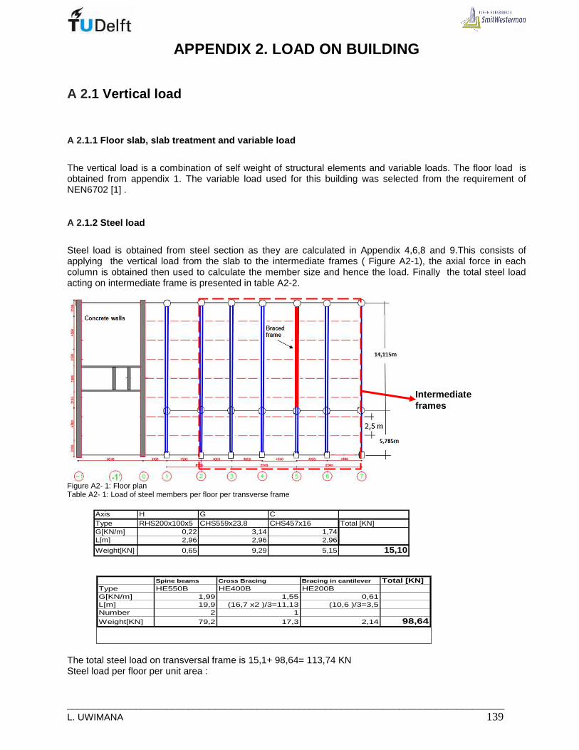
___________________________________________________________________________________ L. UWIMANA 139
APPENDIX 2. LOAD ON BUILDING
A 2.1 Vertical load
A 2.1.1 Floor slab, slab treatment and variable load
The vertical load is a combination of self weight of structural elements and variable loads. The floor load is obtained from appendix 1. The variable load used for this building was selected from the requirement of NEN6702 [1] .
A 2.1.2 Steel load
Steel load is obtained from steel section as they are calculated in Appendix 4,6,8 and 9.This consists of applying the vertical load from the slab to the intermediate frames ( Figure A2-1), the axial force in each column is obtained then used to calculate the member size and hence the load. Finally the total steel load acting on intermediate frame is presented in table A2-2.
Figure A2- 1: Floor plan Table A2- 1: Load of steel members per floor per transverse frame
Axis H G CType RHS200x100x5 CHS559x23,8 CHS457x16 Total [KN]G[KN/m] 0,22 3,14 1,74L[m] 2,96 2,96 2,96
Weight[KN] 0,65 9,29 5,15 15,10
Spine beams Cross Bracing Bracing in cantilever Total [KN]Type HE550B HE400B HE200BG[KN/m] 1,99 1,55 0,61L[m] 19,9 (16,7 x2 )/3=11,13 (10,6 )/3=3,5Number 2 1Weight[KN] 79,2 17,3 2,14 98,64
The total steel load on transversal frame is 15,1+ 98,64= 113,74 KN Steel load per floor per unit area :
Intermediate frames

_____________________________________________________________________________ 140 MSc Thesis
Floor : 2113,741,3 /
19,9.4,25KN m≃
Let’s assume that the total steel weight is 1,5KN/m 2 The total load from floor slab, floor treatment and steel member used in design is presented in table A2-1. Table A2- 2 Load on structure from axes 0 to 7
Structure Type of load Elements Load per memberTotal load per floor[KN/m2] [KN/m2]
Roof Dead load (DL)Element Load[KN/m2]Roof floor 3,14Floor finishing,Ceiling,insulation&installationSteel 1,50Total DL 6,14
Variable load Snow (VL) 1,00Total load 7,14 7,14
7th floor to Dead load (DL)15th floor Floor slab 3,14
Floor finishing,Ceiling, insulation&installationPartition 1,00Steel 1,50Total DL 7,14
Variable load VL 1,75Total load 8,90 8,90
7th floor to Dead load (DL) Floor slab 3,1415th floor Floor finishing,Ceiling,
insulation&installationTotal DL 4,64
Variable load(VL) VL 2,00Total load 6,64 6,64
7th floor to Dead load (DL) slab 3,1415th floor finishing 1,00
DL 4,14Variable load VL 2,00Total load 6,14 6,14
7th floor to Dead load (DL) Total DL 1,1315th floor Variable load VL 2,00
Total load 3,13 3,13
7th floor to Dead load 2KN/m15th floor
Fire escape
Facade
Weight calculation
1,50
1,50
1,50
Roof
Floor slab
Gallerie and Balcons
Stair case
Between axes -1 and 0, there is increase in self weight; therefore the total self weight is 3,88KN/m2 plus other floor treatment which give 7, 9 KN/m2
A2.2 Horizontal load
A.2.2.1 Wind load
The wind pressure acting on building sides was calculated by using NEN 6702;2007 Annex A [1]
dim 1. . . .rep index eq wP C C C pϕ=
Whereby: Prep: representative wind pressure Cdi: Dimension factor; for this building it’s 0,89 Cindex: Wind pressure and suction factors; 0.8+0.4 = 1, 2 Ceq ; pressure settlement factor; = 1

___________________________________________________________________________________ L. UWIMANA 141
φ1 : dynamic amplification factor = 1 pw: wind pressure
21 7 .0,5 . ( )w z wp l V zρ= +
*2,5. .ln( / )w w oV u z d z= − , ( ) ln( / )zw o
kl
z d z=
− , ln( / )w oz d z− ;
71 7l+ ; 20,5.1, 25.v
I (z) : is the turbulence intensity at a height z above the adjacent ground; ρ: is the density of air; = 1.25 kg/m3; z0: is the roughness length in m; 0.7 dw : is the displacement height in meters;35 u *: is friction velocity, in m / s; 2.82 k: is a factor; 0,9 z : height The formula can be put in excel sheet to calculate the representative wind pressure at any height ( see tableA2-3) Table A2- 3: Calculation of Wind pressure h [m] ln(z-dw/zo) Vw 0,9/(ln(z-dw/zo)1+7lz 0.5*1.25*V2
pw prep
4 -0,34 -2,37 -2,67 -17,72 3,52 -0,06 -0,075 0,76 5,37 1,18 9,27 18,04 0,17 0,186 1,27 8,97 0,71 5,95 50,34 0,30 0,327 1,61 11,35 0,56 4,91 80,46 0,40 0,428 1,86 13,12 0,48 4,39 107,56 0,47 0,509 2,06 14,53 0,44 4,06 132,01 0,54 0,57
10 2,23 15,71 0,40 3,83 154,27 0,59 0,6311 2,37 16,72 0,38 3,66 174,72 0,64 0,6812 2,50 17,60 0,36 3,52 193,64 0,68 0,7313 2,61 18,39 0,35 3,42 211,28 0,72 0,7714 2,71 19,09 0,33 3,33 227,81 0,76 0,8115 2,80 19,73 0,32 3,25 243,37 0,79 0,8416 2,88 20,32 0,31 3,19 258,09 0,82 0,8817 2,96 20,86 0,30 3,13 272,05 0,85 0,9118 3,03 21,37 0,30 3,08 285,35 0,88 0,9419 3,10 21,84 0,29 3,03 298,05 0,90 0,9720 3,16 22,28 0,28 2,99 310,20 0,93 0,9921 3,22 22,69 0,28 2,96 321,86 0,95 1,0222 3,27 23,08 0,27 2,92 333,07 0,97 1,0423 3,33 23,46 0,27 2,89 343,86 0,99 1,0624 3,38 23,81 0,27 2,87 354,28 1,02 1,0825 3,42 24,14 0,26 2,84 364,34 1,03 1,1026 3,47 24,46 0,26 2,82 374,08 1,05 1,1227 3,51 24,77 0,26 2,79 383,51 1,07 1,1428 3,56 25,07 0,25 2,77 392,67 1,09 1,1629 3,60 25,35 0,25 2,75 401,55 1,11 1,1830 3,63 25,62 0,25 2,73 410,19 1,12 1,2031 3,67 25,88 0,25 2,72 418,60 1,14 1,2132 3,71 26,13 0,24 2,70 426,78 1,15 1,2333 3,74 26,37 0,24 2,68 434,76 1,17 1,2534 3,77 26,61 0,24 2,67 442,54 1,18 1,2635 3,81 26,84 0,24 2,65 450,14 1,20 1,2836 3,84 27,06 0,23 2,64 457,56 1,21 1,2937 3,87 27,27 0,23 2,63 464,82 1,22 1,3038 3,90 27,48 0,23 2,62 471,91 1,23 1,3239 3,93 27,68 0,23 2,60 478,86 1,25 1,3340 3,95 27,88 0,23 2,59 485,66 1,26 1,3541 3,98 28,07 0,23 2,58 492,32 1,27 1,3642 4,01 28,25 0,22 2,57 498,85 1,28 1,3743 4,03 28,43 0,22 2,56 505,25 1,29 1,3844 4,06 28,61 0,22 2,55 511,54 1,31 1,3945 4,08 28,78 0,22 2,54 517,71 1,32 1,4146 4,11 28,95 0,22 2,53 523,76 1,33 1,4247 4,13 29,11 0,22 2,53 529,71 1,34 1,4348 4,15 29,27 0,22 2,52 535,56 1,35 1,4449 4,17 29,43 0,22 2,51 541,31 1,36 1,4550 4,20 29,58 0,21 2,50 546,96 1,37 1,4651 4,22 29,73 0,21 2,49 552,52 1,38 1,4752 4,24 29,88 0,21 2,49 557,99 1,39 1,4853 4,26 30,02 0,21 2,48 563,38 1,40 1,4954 4,28 30,16 0,21 2,47 568,68 1,41 1,50
The results can be put in graph of height versus representative wind pressure. The figure A2-2 shows that relationship.
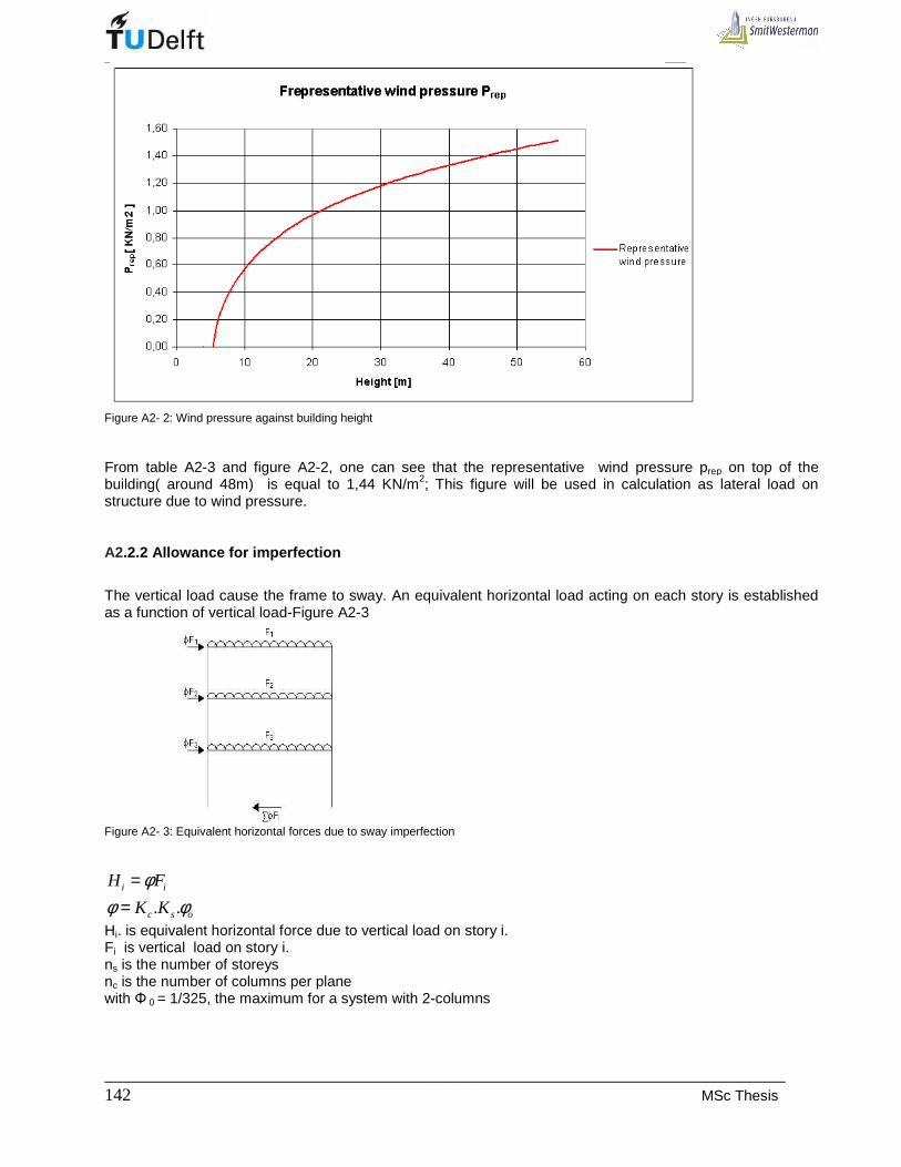
_____________________________________________________________________________ 142 MSc Thesis
Figure A2- 2: Wind pressure against building height From table A2-3 and figure A2-2, one can see that the representative wind pressure prep on top of the building( around 48m) is equal to 1,44 KN/m2; This figure will be used in calculation as lateral load on structure due to wind pressure.
A2.2.2 Allowance for imperfection
The vertical load cause the frame to sway. An equivalent horizontal load acting on each story is established as a function of vertical load-Figure A2-3
Figure A2- 3: Equivalent horizontal forces due to sway imperfection
. .i i
c s o
H F
K K
φφ φ
==
Hi. is equivalent horizontal force due to vertical load on story i. Fi is vertical load on story i. ns is the number of storeys nc is the number of columns per plane with Φ 0 = 1/325, the maximum for a system with 2-columns
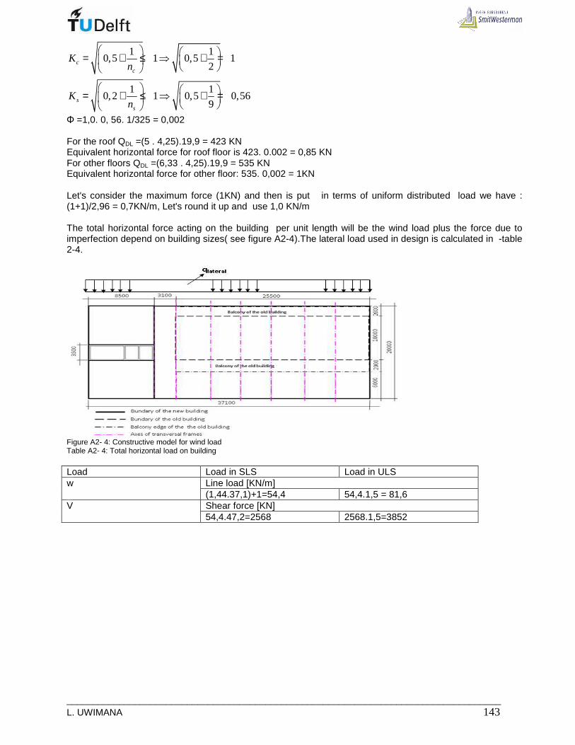
___________________________________________________________________________________ L. UWIMANA 143
1 10,5 1 0,5 1
2
1 10,2 1 0,5 0,56
9
cc
ss
Kn
Kn
= + ≤ ⇒ + =
= + ≤ ⇒ + =
Φ =1,0. 0, 56. 1/325 = 0,002 For the roof QDL =(5 . 4,25).19,9 = 423 KN Equivalent horizontal force for roof floor is 423. 0.002 = 0,85 KN For other floors QDL =(6,33 . 4,25).19,9 = 535 KN Equivalent horizontal force for other floor: 535. 0,002 = 1KN Let's consider the maximum force (1KN) and then is put in terms of uniform distributed load we have : (1+1)/2,96 = 0,7KN/m, Let's round it up and use 1,0 KN/m The total horizontal force acting on the building per unit length will be the wind load plus the force due to imperfection depend on building sizes( see figure A2-4).The lateral load used in design is calculated in -table 2-4.
Figure A2- 4: Constructive model for wind load Table A2- 4: Total horizontal load on building Load Load in SLS Load in ULS
Line load [KN/m] w (1,44.37,1)+1=54,4 54,4.1,5 = 81,6 Shear force [KN] V 54,4.47,2=2568 2568.1,5=3852

_____________________________________________________________________________ 144 MSc Thesis
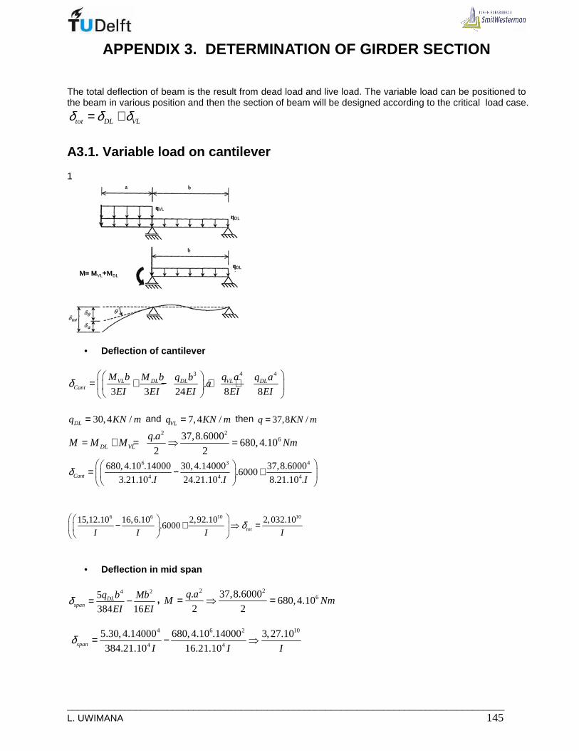
___________________________________________________________________________________ L. UWIMANA 145
APPENDIX 3. DETERMINATION OF GIRDER SECTION
The total deflection of beam is the result from dead load and live load. The variable load can be positioned to the beam in various position and then the section of beam will be designed according to the critical load case.
tot DL VLδ δ δ= +
A3.1. Variable load on cantilever
1
• Deflection of cantilever
43 4
.3 3 24 8 8
VL VLDL DL DLCant
M b q aM b q b q aa
EI EI EI EI EIδ
= + − + +
30,4 /DLq KN m= and 7,4 /VLq KN m= then 37,8 /q KN m=
2 26. 37,8.6000
680,4.102 2DL VL
q aM M M Nm= + = ⇒ =
6 3 4
4 4 4
680,4.10 .14000 30,4.14000 37,8.6000.6000
3.21.10 . 24.21.10 . 8.21.10 .Cant I I Iδ
= − +
6 6 10 1015,12.10 16,6.10 2,92.10 2,032.10.6000 totI I I I
δ
− + ⇒ =
• Deflection in mid span
4 25
384 16DL
span
q b Mb
EI EIδ = − ,
2 26. 37,8.6000
680,4.102 2
q aM Nm= ⇒ =
4 6 2 10
4 4
5.30,4.14000 680,4.10 .14000 3,27.10
384.21.10 16.21.10span I I Iδ = − ⇒

_____________________________________________________________________________ 146 MSc Thesis
A3.2 Variable load on beam part between supports
• Deflection of cantilever
33 4
.3 24 24 8
VLDL DL DLCant
q bM b q b q aa
EI EI EI EIδ
= − − +
2 2
6. 30,4.6000547,2.10
2 2DL
DL
q aM Nm= ⇒ =
6 3 3 4
4 4 4 4
547,2.10 .14000 30,4.14000 7,4.14000 30,4.6000.6000
3.21.10 . 24.21.10 . 24.21.10 . 8.21.10 .Cant I I I Iδ
= − − +
6 6 6 1012,16.10 16,6.10 4,03.10 2,35.10.6000Cant I I I I
δ
= − − +
102,732.10
Cant Iδ −= , upwards deflection
Mid span
4 25 .
384 16span
q b Mb
EI EIδ = − ,
2 26. 30,4.6000
547,2.102 2
DLq aM Nm= ⇒ =
4 6 2 10
4 4
5.37,8.14000 547,2.10 .14000 5,8.10
384.21.10 16.21.10span I I Iδ = − ⇒
A3.2 The required moment of inertia
The results from the two cases of loading show that when variable loads are in mid span a bid beam section
is required. As the deflection is given by this relation 105,8.10
span Iδ = , the required moment of inertia will be
105,8.10
span
Iδ
=

___________________________________________________________________________________ L. UWIMANA 147
APPENDIX 4. STEEL SECTION FOR COLUMN
When looking at the new structure from the 7th floor, the sizes of the structural members are estimated according to the ultimate loads acting on them. Table A4-1 shows the loads used to estimate the size of structural members. By using the hollow core slabs [28], the dead load will be 7,14 KN/m2 floors. The variable loads are 1KN/m2 on the roof and 1,75KN/m2 on the apartment floors according to NEN 6702[1] and the wind load of 54,4 KN/m as it was calculated in Appendix2. Table A4- 1: Load acting on building
Roof
Load [KN/m2]
Spine beams Length [m]
Spine beams spacing [m]
Total load [KN/m2]
Total point load with factor
Dead load 7,14 19,9 4,25 30,3 1,2 36,36
Variable load 1,0 19,9 4,25 4,25 1,5 6,38
Floor
Dead load 7,14 19,9 4,25 30,3 1,2 36,36
Variable load 1,75 19,9 4,25 7,44 1,5 11,16
Facade
Load [KN/m]
Length [m]
Total point load [KN]
Total point load with factor 1,2
Total distributed load with factor 1,5
Wind load 54,4 20,4
Facade load 2 4,25 8,5 10,2
The heavily loaded columns are middle columns in axes 1to 6 (see figure A4-1). The columns size are estimated by using the rules of thumb [10], depending on the axial force due to both self and variable loads each of them bears. The diagonal (bracings) dimensions are estimated from the shear force acting on structure.

_____________________________________________________________________________ 148 MSc Thesis
Floor system spans: 4000 and 4500mm Beam spans : 14115mm and 5785mm cantilever Figure A4- 1: Floor plan showing column position and spine beams The columns sizes are depend on ultimate load from floors dead loads and live load acting on those floors. The dead weight is a combination of floor weight, steel frames, separating walls and floor finishes. The table 4-1 shows the input loads, and by using the matrix frame software the load acting on each column is known.
A4.1 Design load
The model of 4-colums is made and after putting the ultimate loads stated above, the axial load in each column is obtained –figureA4-2. Those loads are used to estimate the size of columns . However the supporting columns are designed according to the total reaction forces in supports.
Figure A4- 1 Ultimate axial load in columns
A4. 2. Estimation of column sizes
The columns sizes can be estimated by using the rules of thumb of steel [10]. The obtained size can also be checked if it fits all the stability requirements. The circular hollow section was selected for supporting columns. It is an attractive sections the strength and stiffness in both directions are the same, in addition the circular hollow section is much better placed to torque the I or H-sections. The columns sizes are estimated and shown in in table A4-2.
• Axis G (support columns)
G C Braced frame Braced frame Axial force[KN] = Reaction force
6658 2749

___________________________________________________________________________________ L. UWIMANA 149
Lbuc= 2,80m Axial load F = 6658 KN Steel class S235 with yield strength of 235N/mm2
The required steel section is : 3
26658.1028332
235st sty
FA A mm
f= ⇒ = =
Choose CHS 559x23,8 D=559mm t=23,8mm A = 400cm2 Iy=143563cm4 i = 18,9cm Wy= 6822cm3 G= 3,14KN/m Stability Verification
bucy
y
L
iλ =
yy
Ii
A=
,
2100003,14 94
235d
ey d
E
fλ π= ⇒ =
.94y buc
rele y
L
i
λλ
λ= ⇒
28000,2 1,0
.94 189.94rel buc
L
iλ λ ω= ⇒ = ≈ ⇒ =
36936.101,0 0,74 1,0
. . 1,0.40000.235buc y
F
A fω≤ ⇒ = ≤ , OK
• Axis C (support columns)
Axis G (support column) Lbuc= 2,80m Axial load F = 2749 KN Steel class S235 with yield strength of 235N/mm2
The required steel section is : 3
22868.1011698
235st sty
FA A mm
f= ⇒ = =
Choose CHS 457x16, D=457mm t=16mm A = 222cm2 Iy=53959cm4 i = 15,6cm Wy= 3113cm3 G= 1,74 KN
28000,2 1,0
.94 156.94rel buc
L
iλ λ ω= ⇒ = ≈ ⇒ =
32868.101,0 0,55 1,0
. . 1,0.22200.235buc y
F
A fω≤ ⇒ = ≤ , OK
• Axis H (Facade columns)
Axis G (support column) Lbuc= 2,96m Axial load F = 8,5 KN ( Facade load) Steel class S235 with yield strength of 235N/mm2
The required steel section is : 3
28,5.1036
235st sty
FA A mm
f= ⇒ = =
Choose RHS 200x100x5 A = 28,7cm2 Iy=1495cm4 i = 7,21cm
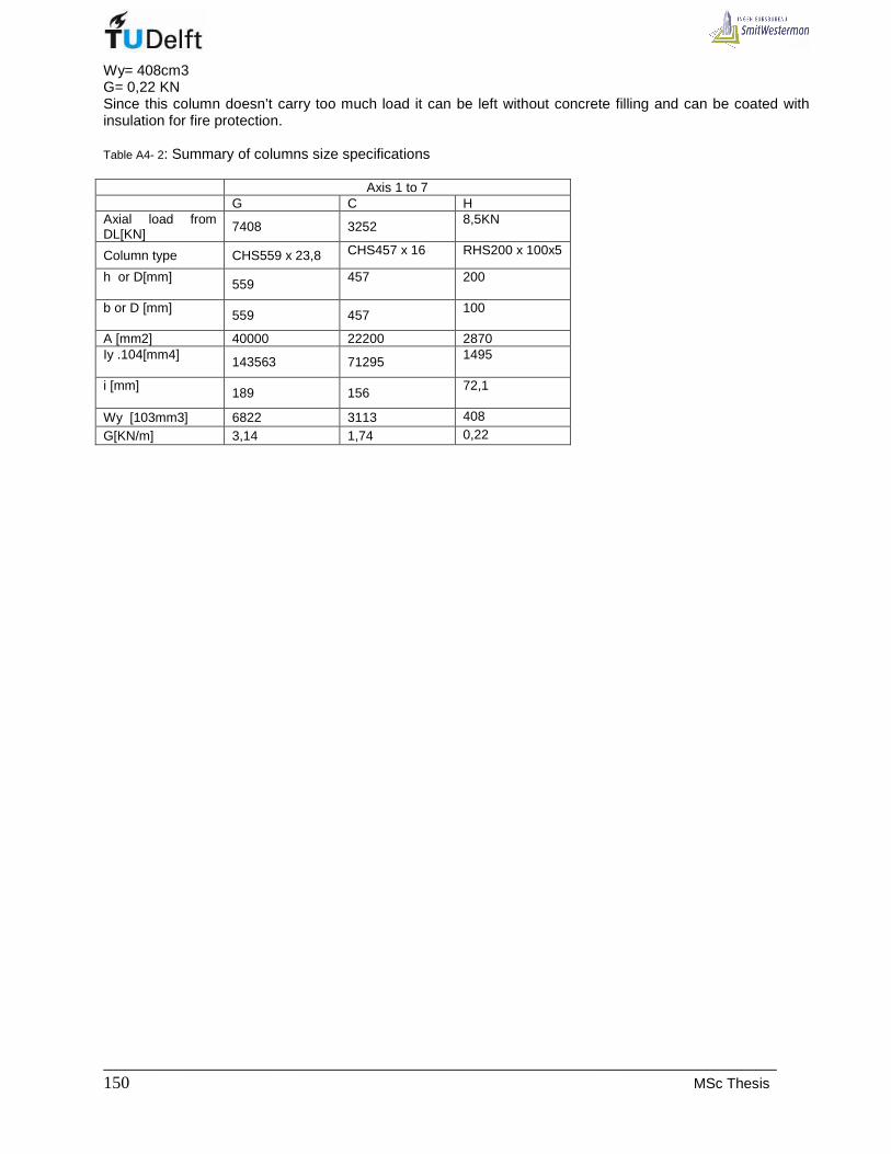
_____________________________________________________________________________ 150 MSc Thesis
Wy= 408cm3 G= 0,22 KN Since this column doesn’t carry too much load it can be left without concrete filling and can be coated with insulation for fire protection. Table A4- 2: Summary of columns size specifications Axis 1 to 7 G C H Axial load from DL[KN] 7408 3252 8,5KN
Column type CHS559 x 23,8 CHS457 x 16 RHS200 x 100x5
h or D[mm] 559 457 200
b or D [mm] 559 457 100
A [mm2] 40000 22200 2870 Iy .104[mm4] 143563 71295 1495
i [mm] 189 156 72,1
Wy [103mm3] 6822 3113 408
G[KN/m] 3,14 1,74 0,22

___________________________________________________________________________________ L. UWIMANA 151
APPENDIX 5: DESIGN OF COMPOSITE COLUMNS
The steel columns designed in appendix 4 have relatively large dimensions. The way of reducing their size and to have the same capacity is by using composite columns. The design is made according to Euro Code 4 [5] and the Structural Hollow Sections (SHS) filled with concrete were selected because they are the most efficient of all structural steel sections in resisting compression. It is also a method of fire protection of the steel sections. The columns are located on sides of the old building in order to carry the new structure put on top of the old building. These column will be visible and the more pleasant shape will be circular hollow section (CHS) filled with concrete. The columns in axis 1,3 and 5 will be used to design all columns in axes 1 to 7.
A5.1. Design of supporting columns in axis G, frame 1 to 7
These are heavily loaded columns in this section of the building. It is assumed that the circular hollow sections are to be with70% preliminary steel contribution to the load carrying capacity. The design load is 7408 KN according to the appendix 4. (i). Material properties. Steel It is assumed that the rectangular hollow sections are to be with70% preliminary steel contribution to the load carrying capacity. The required steel section is
320.7. 0,7.6658.10
19832235a
y
FA mm
f= ⇒ =
FigureA5- 1 Location of column section in axes G A circular hollow section of 457 mm diameter and 16mm thickness is chosen (CHS 457x16) The columns have to be checked for local buckling, the circular hollow sections must be satisfy this requirement:
290h
tε≤
t : is the wall thickness of the steel hollow section in mm. h: is the larger outer dimension of the rectangular hollow section in mm.

_____________________________________________________________________________ 152 MSc Thesis
235
yfε =
2351,0
235ε = =
yf : is the yield strength of the steel section in N/mm².
457
28,616≃
< 90, OK Therefore the column has the following properties: CHS 457, 4 x 16
;y df= 235 N/mm2 (
1,0sγ =)
Ed = 210000 N/mm2 Aa = 22200 mm2, Ia = 53959. 104 mm4 Concrete. Area of concrete:
( )2
2457 (16.2)141791
4cA mmπ−
= =
Concrete moment of inertia:
( )4
8 4457 (16.2)(16.10 )
64c s c sI I I I mmπ−
= − ⇒ = −
The concrete strength is C25/30 225 /ckf N mm= (
1,5cγ =)
230500 /cmE N mm= (
1,35sγ =)
Longitudinal reinforcement steel According to EC4 [5], the longitudinal reinforcement steel depends on concrete area and has the following limitation:
0% 6%s
c
A
A≤ =
22.141791 2836
100sA mm= =
Assume As = 2% Ac ;
Use 210 20 3142sA mmφ ⇒ = ; equivalent to 2,2% which is always within the limit.
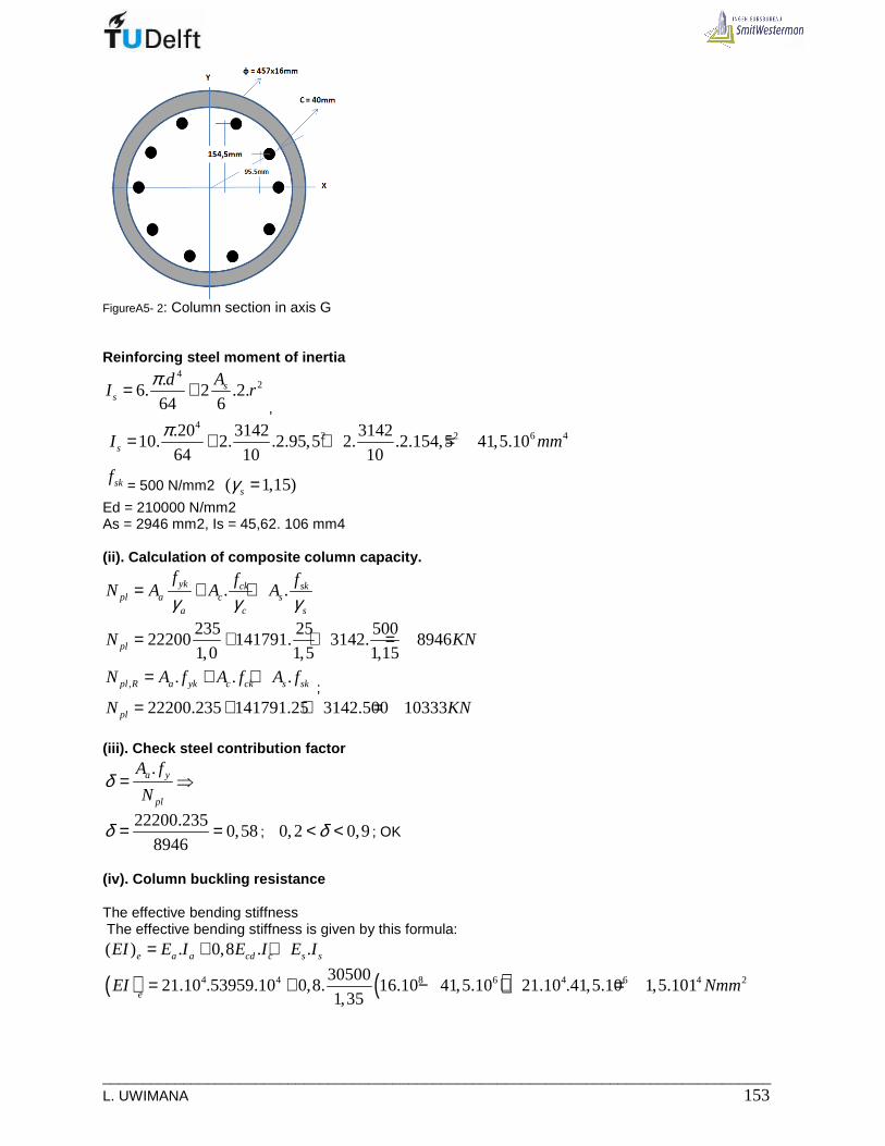
___________________________________________________________________________________ L. UWIMANA 153
FigureA5- 2: Column section in axis G Reinforcing steel moment of inertia
42.
6. 2 .2.64 6
ss
AdI r
π= + ,
4
2 2 6 4.20 3142 314210. 2. .2.95,5 2. .2.154,5 41,5.10
64 10 10sI mmπ= + + =
skf= 500 N/mm2 ( 1,15)sγ =
Ed = 210000 N/mm2 As = 2946 mm2, Is = 45,62. 106 mm4 (ii). Calculation of composite column capacity.
. .yk ck skpl a c s
a c s
f f fN A A A
γ γ γ= + +
235 25 500
22200 141791. 3142. 89461,0 1,5 1,15plN KN= + + =
, . . .pl R a yk c ck s skN A f A f A f= + + ;
22200.235 141791.25 3142.500 10333plN KN= + + =
(iii). Check steel contribution factor
.a y
pl
A f
Nδ = ⇒
22200.235
0,588946
δ = = ; 0,2 0,9δ< < ; OK
(iv). Column buckling resistance The effective bending stiffness The effective bending stiffness is given by this formula: ( ) . 0,8 . .e a a cd c s sEI E I E I E I= + +
( ) ( )4 4 8 6 4 6 4 23050021.10 .53959.10 0,8. 16.10 41,5.10 21.10 .41,5.10 1,5.101
1,35eEI Nmm= + − + =
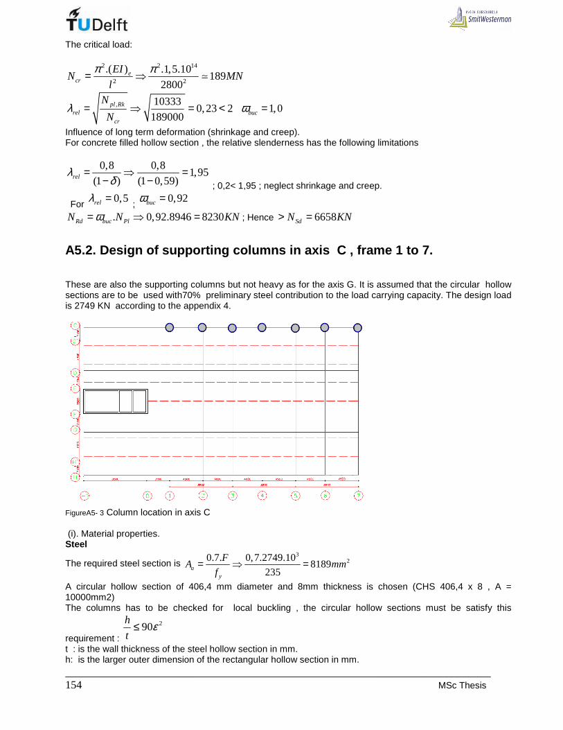
_____________________________________________________________________________ 154 MSc Thesis
The critical load:
2 2 14
2 2
.( ) .1,5.10189
2800e
cr
EIN MN
l
π π= ⇒ ≃
, 103330,23 2
189000pl Rk
relcr
N
Nλ = ⇒ = < 1,0bucω =
Influence of long term deformation (shrinkage and creep). For concrete filled hollow section , the relative slenderness has the following limitations
0,8 0,81,95
(1 ) (1 0,59)relλδ
= ⇒ =− − ; 0,2< 1,95 ; neglect shrinkage and creep.
For 0,5relλ =
; 0,92bucω =
. 0,92.8946 8230Rd buc PlN N KNω= ⇒ = ; Hence 6658SdN KN> =
A5.2. Design of supporting columns in axis C , fra me 1 to 7.
These are also the supporting columns but not heavy as for the axis G. It is assumed that the circular hollow sections are to be used with70% preliminary steel contribution to the load carrying capacity. The design load is 2749 KN according to the appendix 4.
FigureA5- 3 Column location in axis C (i). Material properties. Steel
The required steel section is 3
20.7. 0,7.2749.108189
235ay
FA mm
f= ⇒ =
A circular hollow section of 406,4 mm diameter and 8mm thickness is chosen (CHS 406,4 x 8 , A = 10000mm2) The columns has to be checked for local buckling , the circular hollow sections must be satisfy this
requirement :
290h
tε≤
t : is the wall thickness of the steel hollow section in mm. h: is the larger outer dimension of the rectangular hollow section in mm.

___________________________________________________________________________________ L. UWIMANA 155
235
yfε =
2351,0
235ε = =
yf : is the yield strength of the steel section in N/mm².
406,451
8≃
< 90 , OK Therefore the column has the following properties: CHS406,4 x8
;y df= 235 N/mm2 (
1,0sγ =)
Ed = 210000 N/mm2 Aa = 10000 mm2, Ia = 19874. 104 mm4 Concrete.
Area of concrete:
( )2
2406,4 (8.2)119644
4cA mmπ−
= =
Concrete moment of inertia:
( )4
8 4406,4 (8.2)(11,4.10 )
64c s c sI I I I mmπ−
= − ⇒ = −
The concrete strength is C25/30 225 /ckf N mm= (
1,5cγ =)
230500 /cmE N mm= (
1,35sγ =)
Longitudinal reinforcement steel According to EC4 , the longitudinal reinforcement steel depends on concrete area and has the following
limitation:
0% 6%s
c
A
A≤ =
Assume As = 2% Ac ;
22.119644 2393
100sA mm= =
Use 28 20 2512sA mmφ ⇒ =
; equivalent to 2% which is always within the limit.
FigureA5- 4: Column section in axis C
Reinforcing steel moment of inertia:
42 2
1 2
.8. 2 .2. .2.
64 8 8s s
s
A AdI r r
π= + + ,
42 2 6.20 2512 2512
8. 2. .2.102,7 1. .2.145,2 26,6.1064 8 8sI
π= + + =

_____________________________________________________________________________ 156 MSc Thesis
skf= 500 N/mm2 (
1,15sγ =)
Ed = 210000 N/mm2 As = 2512 mm2, Is = 26,6. 106 mm4 (ii). Calculation of composite column capacities.
. .yk ck skpl a c s
a c s
f f fN A A A
γ γ γ= + +
235 25 500
10000 119644. 2512.1,0 1,5 1,15
2350 1994 1093 5437
pl
pl
N
N KN
= + +
= + + =
, . . .pl R a yk c ck s skN A f A f A f= + + ;
, 10000.235 119644.25 2512.500 6597pl RkN KN= + + =
(iii). Check steel contribution factor
3
. 10000.2350,43
5437.10a y
pl
A f
Nδ = ⇒ =
0,2 0,9δ< < ; Ok (iv). Column buckling resistance The effective bending stiffness
The effective bending stiffness is given by this formula:( ) . 0,8 . .e a a cd c s sEI E I E I E I= + +
( )4 4 8 6 4 630500( ) 21.10 .19874.10 0,8. 11,4.10 26,6.10 21.10 .26,6.10
1,35eEI = + − +
13 13 12 13 2( ) 4,2.10 2.10 5,6.10 6,76.10eEI Nmm= + + =
The critical load: 2 2 13
2 2
.( ) .6,76.1085
2800e
cr
EIN MN
l
π π= ⇒ ≃
, 65970,3 2
85000pl Rk
relcr
N
Nλ = ⇒ = < 1,0bucω =
Influence of long term deformation (shrinkage and creep). For concrete filled hollow section , the relative slenderness has the following limitations
0,6 0,61,05
(1 ) (1 0,43)relλδ
= ⇒ =− −
0,3< 1,05 ; neglect shrinkage and creep 0,3relλ = and 0,98bucω =
.
For 0,5relλ =
; 0,92bucω =
. 0,98.5437 5328Rd buc plN N KNω= ⇒ = 2749RdN KN> =
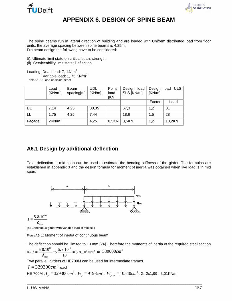
___________________________________________________________________________________ L. UWIMANA 157
APPENDIX 6. DESIGN OF SPINE BEAM
The spine beams run in lateral direction of building and are loaded with Uniform distributed load from floor units, the average spacing between spine beams is 4,25m. Fro beam design the following have to be considered: (i). Ultimate limit state on critical span: strength (ii). Serviceability limit state; Deflection Loading: Dead load: 7, 14/ m2 Variable load: 1, 75 KN/m2
TableA6- 1: Load on spine beam Load
[KN/m2] Beam spacing[m]
UDL [KN/m]
Point load [KN]
Design load SLS [KN/m]
Design load ULS [KN/m]
Factor Load
DL 7,14 4,25 30,35 67,3 1,2 81
LL 1,75 4,25 7,44 18,6 1,5 28
Façade 2KN/m 4,25 8,5KN 8,5KN 1,2 10,2KN
A6.1 Design by additional deflection
Total deflection in mid-span can be used to estimate the bending stiffness of the girder. The formulas are established in appendix 3 and the design formula for moment of inertia was obtained when live load is in mid span.
105,8.10
span
Iδ
=
(a) Continuous girder with variable load in mid field FigureA6- 1: Moment of inertia of continuous beam The deflection should be limited to 10 mm [24]. Therefore the moments of inertia of the required steel section
is: 10 10
9 45,8.10 5,8.105,8.10
10span
I mmδ
= ⇒ = or 4580000cm
Two parallel girders of HE700M can be used for intermediate frames. 4329300I cm= each
HE 700M ; 4329300yI cm= ; 39198yW cm= ; 3, 10540y plW cm= ; G=2x1,99= 3,01KN/m
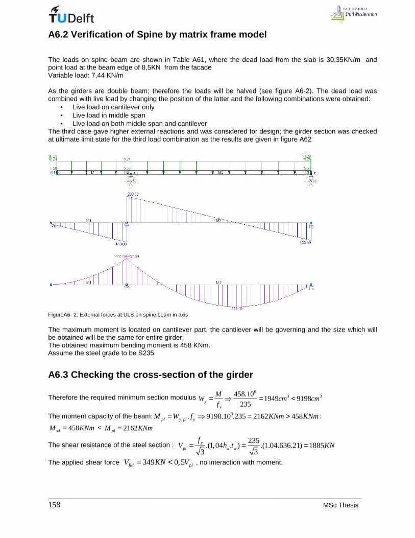
_____________________________________________________________________________ 158 MSc Thesis
A6.2 Verification of Spine by matrix frame model
The loads on spine beam are shown in Table A61, where the dead load from the slab is 30,35KN/m and point load at the beam edge of 8,5KN from the facade Variable load: 7,44 KN/m As the girders are double beam; therefore the loads will be halved (see figure A6-2). The dead load was combined with live load by changing the position of the latter and the following combinations were obtained:
• Live load on cantilever only • Live load in middle span • Live load on both middle span and cantilever
The third case gave higher external reactions and was considered for design; the girder section was checked at ultimate limit state for the third load combination as the results are given in figure A62
FigureA6- 2: External forces at ULS on spine beam in axis The maximum moment is located on cantilever part, the cantilever will be governing and the size which will be obtained will be the same for entire girder. The obtained maximum bending moment is 458 KNm. Assume the steel grade to be S235
A6.3 Checking the cross-section of the girder
Therefore the required minimum section modulus 6
3 3458.101949 9198
235yy
MW cm cm
f= ⇒ = <
The moment capacity of the beam: 3, . 9198.10 .235 2162 458pl y pl yM W f KNm KNm= ⇒ = > :
458sdM KNm= < 2162plM KNm=
The shear resistance of the steel section : 235
.(1,04 . ) .(1.04.636.21) 18853 3y
pl w w
fV h t KN= = =
The applied shear force 349 0,5Rd plV KN V= < , no interaction with moment.

___________________________________________________________________________________ L. UWIMANA 159
A6.4 Checking the deflection of the girder
The maximum deflection of the spine beam at cantilever should be max;
578523
250 250cant
Lmmδ = ⇒ = and in
the middle spanmax;
1411556
250 250field
Lmmδ = ⇒ =
In serviceability limit state, the maximum deflection of the cantilever is obtained in load case 1; 10mm ( Figure A6-3,this is less than the allowable deflection of 23mm. In the middle span , load case 2 give a deflection of 21mm( Figure A8-3) which is less than 56mm, the allowable maximum deflection in middle field. LC1
LC2
LC3
FigureA6- 3: Beam deflection

_____________________________________________________________________________ 160 MSc Thesis
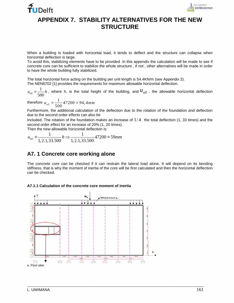
___________________________________________________________________________________ L. UWIMANA 161
APPENDIX 7. STABILITY ALTERNATIVES FOR THE NEW STRUCTURE
When a building is loaded with horizontal load, it tends to deflect and the structure can collapse when horizontal deflection is large. To avoid this, stabilizing elements have to be provided .In this appendix the calculation will be made to see if concrete core can be sufficient to stabilize the whole structure , if not , other alternatives will be made in order to have the whole building fully stabilized. The total horizontal force acting on the building per unit length is 54,4KN/m (see Appendix 2). The NEN6702 [1] provides the requirements for maximum allowable horizontal deflection.
1
500allu h= , where h, is the total height of the building, and allu , the allowable horizontal deflection
therefore 1
47200 94, 4500allu mm= =
Furthermore, the additional calculation of the deflection due to the rotation of the foundation and deflection due to the second order effects can also be Included. The rotation of the foundation makes an increase of 1/ 4 the total deflection (1, 33 times) and the second order effect for an increase of 20% (1, 20 times). Then the new allowable horizontal deflection is:
1 147200 59
1,2.1,33.500 1,2.1,33.500allu h mm= ⇒ =
A7. 1 Concrete core working alone
The concrete core can be checked if it can restrain the lateral load alone. It will depend on its bending stiffness, that is why the moment of inertia of the core will be first calculated and then the horizontal deflection can be checked.
A7.1.1 Calculation of the concrete core moment of i nertia
a. Floor plan

_____________________________________________________________________________ 162 MSc Thesis
b. Concrete core. FigureA7- 1: Floor plan showing concrete core as lateral load restraining structure The total area : 8,695x 3,300= 28,7.106 mm2 The area of voids: (4,505 x 2,900) + [2(1700 x 2900)] = 22, 9.106 mm2 The net Area: 28,7.106 – 22,9.106 = 5,8. 106 mm 2
• Moment of inertia in X- axis ( I ) In X-axis, the moment of inertia will be the sum of the individual moment of inertia of transverse walls , plus the contribution of the longitudinal walls.
3 3 3 2 12 41 1 1220.3100 250.3100 2. 160.3100 2.8460.200.1550 10,1.10
12 12 12I mm= + + + =
• Polar moment of inertia in X- axis (I t)
t x yI I I= + , with 2
y yc yI I Ad= +
2x xc xI I Ad= +
With thin walled section, xcI and xcI are negligible; 2 2
t x yI Ad Ad= +
2 2 2 2
2
12 4
3100.220.4230 3100.160.465 3100.160.2325 3100.250.4230
2.8460.200.1550
37.10
t
t
I
I mm
= + + + +
=
A7.1.2 Main stabilizing structure derivation equati ons
As the core is eccentrically located in the floor plan, the wind load causes two kind of movement considering the far away point (A) from the core:
ru : movement due to rotation
bu : movement due to bending

___________________________________________________________________________________ L. UWIMANA 163
FigureA7- 2: Eccentricity of the core
FigureA7- 3: Possible movement (translation and rotation) of the building due to lateral load
• Bending bu
The bending displacement is given by the following relation: 4
8b
whu
EI= ,
Where w: wind load h: building height I : moment of inertia E: Modulus of elasticity of concrete
• Rotation ru

_____________________________________________________________________________ 164 MSc Thesis
ru , is determined by the angle “phi” and the distance (d) from the rotational center to the point A.
The equation for the angle “phi” is from the Mt-line
FigureA7- 4: m, Mt, and phi diagrams
The equation for Mt is: (1). 1tM mx C= − +
ϕ is obtained by integrating the equation (1): (2). 21 2
1
2tGI mx C x Cϕ = − + +
The integration constants C1 and C2 are calculated from the following boundary conditions: (1).
10 . 0tx h M mh C= → = →− + =
1 .
( )t
C m h
M m h x
== −
(2). 22
10 0 .0 .0 0
2x m h Cϕ= → = →− + + =
2 0
1(2 )
2t
C
GI mx h xϕ
=
= −
maxϕ is obtained at x h=
max
2max
2
max
1(2 )
21
21
2
t
t
t
GI mh h h
GI mh
mh
GI
ϕ
ϕ
ϕ
= −
=
=
ru is maxϕ multiplied by ‘d’
2
max
1. . .
2rt
mhu d d
GIϕ= ⇒ Where: .m w e=
w = wind load h = Height of the building
tI = Torsion moment of inertia
2(1 )
EG
v=
+ with 0, 2v = ;
5
12G E=
By replacing the G-value in the equation of ru , one obtains,
___________________________________________________________________________________ L. UWIMANA 165
2 21 6 ( . ). . . .
52 51 2
rt
t
m h w e hu d d
E IE I
= =
26. . .
5rt
whu e d
EI=
Finally the equation for the movement of point A is the sum of bu and ru
4 26 ( . ).
8 5At
w h w e hu d
E I E I= +
Where: d is distance from core center to the point A e: is the eccentricity of core with respect to the center of rotation
A7.1.3 Check for the actual deflections
The deflection of the building edge (point A) can be calculated using the obtained formula. In precast structure, high Concrete grade is required. By using B45, its properties are shown in tableA7 –according to NEN-EN 2 [17] TableA7- 1: Concrete B45 properties
Concrete grade B45
fck [N/mm2] 45
fcm [N/mm2] 53
fctm [N/mm2] 3,8
Ecm [kN/mm2] 36
4 2
12 12
54, 4 .47200 6 (54, 4 .14320)47200.32870
8.36000.10,1 .10 5 36000.37.10
93 51 144
A
A
u
u m m
= +
= + =
A7.1.4 increasing the sizes of walls that make the core. As the horizontal deflection is too big due to small lateral stiffness of the core, one can increase the sizes of some walls( see Figure A8-5) and thereafter recalculating the moment of inertia as well as the deflection.

_____________________________________________________________________________ 166 MSc Thesis
FigureA7- 5: Increased core dimensions
• The new moment of inertia :
3 3 2 12 41 12. 250.3100 2. 200.3100 2.8460.250.1550 12,4.10
12 12I mm= + + =
( ) 28695.3500 4505.3000 2(1700.3000) 6717500CoreA mm= − + =
• The new polar moment of inertia in X- axis (I t)
2 2 2 2
2
12 4
3100.250.4230 3100.200.465 3100.200.2325 3100.250.4230
2.8460.250.1550
41,4.10
t
t
I
I mm
= + + + +
=
4 2 4 2
1 2 1 2
6 ( . ) 5 4 , 4 .4 7 2 0 0 6 (5 4 , 4 .1 4 3 2 0 ) 4 7 2 0 0. .3 2 8 7 0
8 5 8 .3 6 0 0 0 .1 2 , 4 .1 0 5 3 6 0 0 0 .4 1, 4 .1 0
1 2 2
At
w h w e hu d
E I E I
m m
= + ⇒ +
=
Even if the core dimension are increased but yet the resulting deflection continues to be bigger than the required value. Other alternatives can be developed.
A7.2 Concrete core with the existing building
A7.2.1 Upper part
• Forces in bracing structures
The bracing structure is only the core, it is subjected to translation and rotation. Each component is calculated and summed up to get the total force acting on bracing structure.
,, .;
,1
.y iy transl i yn
y ii
IF W
I=
=∑
and
( ),
, ,2 2
, ,1
..
. .
y i iy rotation i Tn
y i i x i ii
I xF M
I x I y=
+∑
,y iI and ;x iI : moment of inertia of bracing structures i, in Y and X- direction
yW : Total lateral forces action on floor level

___________________________________________________________________________________ L. UWIMANA 167
, .;y transl iF and , .;y rotation iF : Translation and rotation force acting on bracing structure i
ix and iy : Distance from rotation center to structure I, in X and Y – direction.
TM :Tortional moment .T yM W e= ; where e is the eccentricity
• Moment of inertia of concrete core
Concrete core: 12 412,4.10yI mm= and 12 476,8.10xI mm=
• Moment of inertia of steel frame and old building
2 2,1 7 ' '. .old F F C CI A L A L− = + 2 2 12 4
,1 7 510.210.1765 510.210.8150 7,45.10oldI mm− = + =
3
13 4,in f
210.100001,75.10
12y illI mm− = =
12 4, 17,5 7,45 16 41.10y totalI mm= + + =
, 0x totalI = is negligible for each frame
,, .;
,1
. 2018y iy transl i yn
y ii
IF W KN
I=
= =∑
( ),
, ,2 2
, ,1
..
. .
y i iy rotation i Tn
y i i x i ii
I xF M
I x I y=
+∑,
( )12
, , 12 2 12 2
12,4.10 .4,250.2018.14,300 6790
12,4.10 .4,250 76,8.10 .0y rotation iF KN=
+
A7.2.2 Lower part
• Location of the rotation center
,1
,1
.n
y i ii
c n
y ii
I xx
I
=
=
=∑
∑
,1
,1
.0
n
x i ii
c cn
x ii
I yy y
I
=
=
= ⇒ =∑
∑

_____________________________________________________________________________ 168 MSc Thesis
Figure A7-8: Location of rotation centre in plan(core and old building frames frame) in floor 0 to 7
• Forces in bracing structures
a. Translation
(i) In core : 12
, , 12
12,4.10.2018 84
(12,4 7(41)).10y transl coreF KN= =+
(ii) In steel frame and old building: 12
, , 12
41.10.2018 276
(12,4 7(41)).10y transl frameF KN= =+
for each frame
b. Rotation The rotation component is calculated using the formula stated above and the values are put in table A7-3. It has been obtained that the rotation force is 0 for all bracing members( frames).
Table A7-3: Rotation component in bracing member:
Wy e MT Iy Ix xi xi 2 yi yi 2 Iy.xi Iy.xi 2 Ix.yi 2 ΣΣΣΣ(Iyxi2+ Fy; rot= (Ι(Ι(Ι(Ι y.xi)/
KN mm KNmm mm 4 mm 4Ixi.yi2) ΣΣΣΣ(Iyxi2+Ixi.yi2))MT
W1 2018 4933 9954794 4,10E+13 0,00E+00 11883 1E+08 3192,5 1E+07 4,87E+17 5,79E+21 0,00E+00 1,93E+02
W2 2018 4933 9954794 4,10E+13 0,00E+00 7383 5E+07 3192,5 1E+07 3,03E+17 2,23E+21 0,00E+00 1,20E+02
W3 2018 4933 9954794 4,10E+13 0,00E+00 3383 1E+07 3192,5 1E+07 1,39E+17 4,69E+20 0,00E+00 5,48E+01
W4 2018 4933 9954794 4,10E+13 0,00E+00 617 380689 3192,5 1E+07 2,53E+16 1,56E+19 0,00E+00 1,00E+01
W5 2018 4933 9954794 4,10E+13 0,00E+00 5117 3E+07 3192,5 1E+07 2,10E+17 1,07E+21 0,00E+00 8,29E+01
W6 2018 4933 9954794 4,10E+13 0,00E+00 9117 8E+07 3192,5 1E+07 3,74E+17 3,41E+21 0,00E+00 1,48E+02
W7 2018 4933 9954794 4,10E+13 0,00E+00 13617 2E+08 3192,5 1E+07 5,58E+17 7,60E+21 0,00E+00 2,21E+02
Core 2018 4933 9954794 1,24E+13 7,68E+13 19233 4E+08 0 0 2,38E+17 4,59E+21 0,00E+00 9,43E+01
2,52E+22 0,00E+00 2,52E+22
Table A7-4: Forces acting on bracing members Lower
Translation Rotation Total force Height UDLKN KN KN m N/m
W1 276 193 469 20.56 23W2 276 120 396 20.56 19W3 276 55 331 20.56 16W4 276 10 286 20.56 14W5 276 83 359 20.56 17W6 276 148 424 20.56 21W7 276 221 497 20.56 24
Core 84 94 178 20.56 9
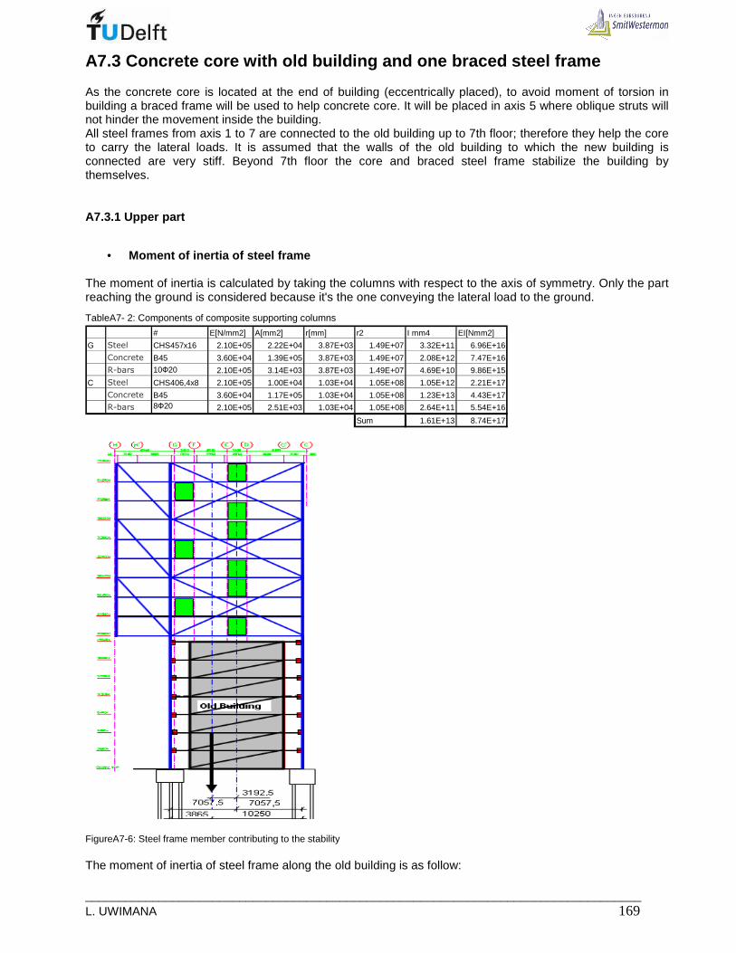
___________________________________________________________________________________ L. UWIMANA 169
A7.3 Concrete core with old building and one braced steel frame
As the concrete core is located at the end of building (eccentrically placed), to avoid moment of torsion in building a braced frame will be used to help concrete core. It will be placed in axis 5 where oblique struts will not hinder the movement inside the building. All steel frames from axis 1 to 7 are connected to the old building up to 7th floor; therefore they help the core to carry the lateral loads. It is assumed that the walls of the old building to which the new building is connected are very stiff. Beyond 7th floor the core and braced steel frame stabilize the building by themselves.
A7.3.1 Upper part
• Moment of inertia of steel frame
The moment of inertia is calculated by taking the columns with respect to the axis of symmetry. Only the part reaching the ground is considered because it's the one conveying the lateral load to the ground.
TableA7- 2: Components of composite supporting columns
# E[N/mm2] A[mm2] r[mm] r2 I mm4 EI[Nmm2]
G Steel CHS457x16 2.10E+05 2.22E+04 3.87E+03 1.49E+07 3.32E+11 6.96E+16
Concrete B45 3.60E+04 1.39E+05 3.87E+03 1.49E+07 2.08E+12 7.47E+16
R-bars 10Ф20 2.10E+05 3.14E+03 3.87E+03 1.49E+07 4.69E+10 9.86E+15
C Steel CHS406,4x8 2.10E+05 1.00E+04 1.03E+04 1.05E+08 1.05E+12 2.21E+17
Concrete B45 3.60E+04 1.17E+05 1.03E+04 1.05E+08 1.23E+13 4.43E+17
R-bars 8Ф20 2.10E+05 2.51E+03 1.03E+04 1.05E+08 2.64E+11 5.54E+16
Sum 1.61E+13 8.74E+17
FigureA7-6: Steel frame member contributing to the stability The moment of inertia of steel frame along the old building is as follow:

_____________________________________________________________________________ 170 MSc Thesis
12 416.10I mm= It is this moment of inertia which will be used, because it is given by those columns connected to the foundation.
• Moment of inertia of concrete core It is taken after increasing the wall sizes of core
12 412,4.10yI mm= and 2 12 42(8500.250).4250 76,8.10xI mm = =
• Location of the rotation center
( )12 12 17,
112 12
,1
.12, 4.10 .4250 16.10 .28600 5,103.10
1796812, 4 16 .10 28, 4.10
n
y i ii
c cn
y ii
I xx x mm
I
=
=
+= ⇒ = = =+
∑
∑
12,1
12
,1
.76,8.10 .0 0
076,8.10
n
x i ii
c cn
x ii
I yy y mm
I
=
=
+= ⇒ = =∑
∑
FigureA7-7: Location of rotation centre in plan(core and one frame) in floor 7 to 15
• Forces in bracing structures
(i) In core
12
, , 12
12,4.10.2018 881
(12,4 16).10y transl coreF KN= =+
{ }12
, , 12 2 12 2 12 2
12,4.10 .13718.2018.582 48
12,4.10 .13718 16.10 10632 ) 76,8.10 .0 0y rotation coreF KN= =
+ + +
(ii) In steel frame
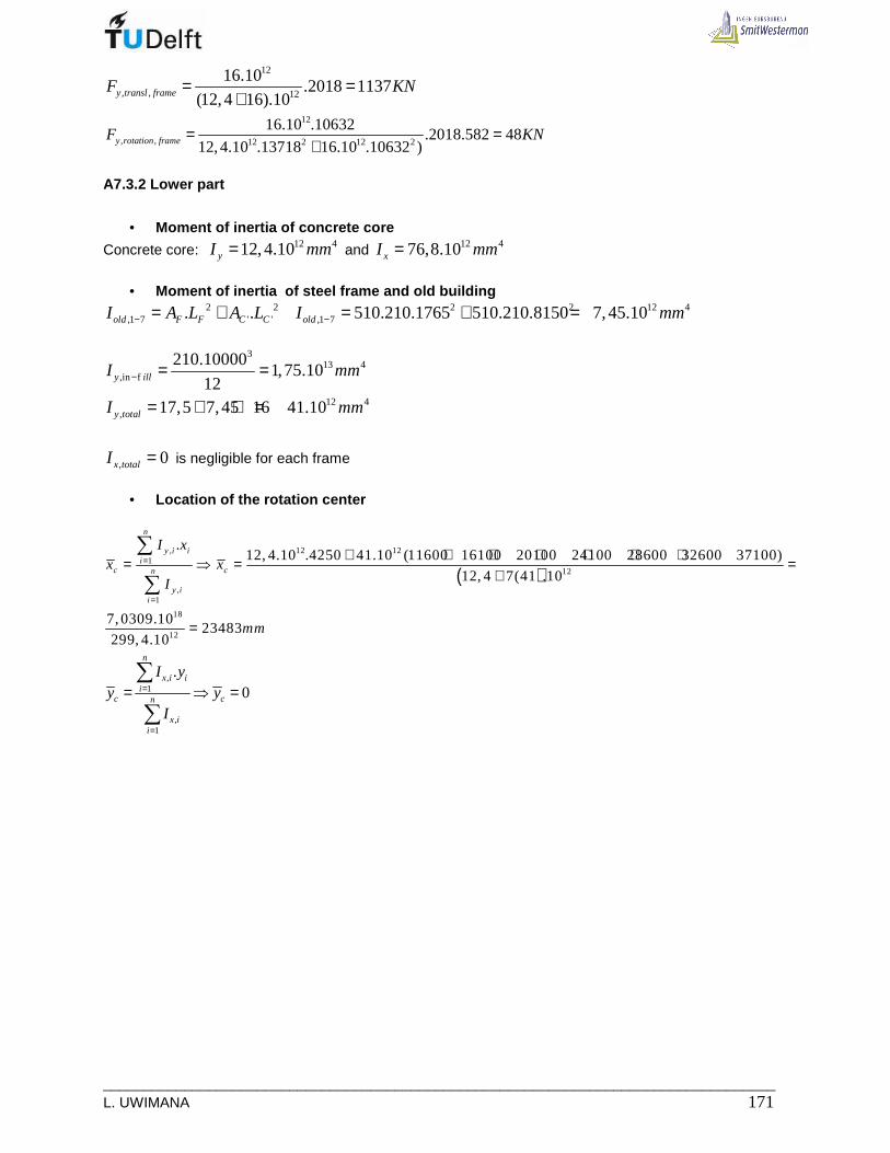
___________________________________________________________________________________ L. UWIMANA 171
12
, , 12
16.10.2018 1137
(12,4 16).10y transl frameF KN= =+
12
, , 12 2 12 2
16.10 .10632.2018.582 48
12,4.10 .13718 16.10 .10632 )y rotation frameF KN= =+
A7.3.2 Lower part
• Moment of inertia of concrete core
Concrete core: 12 412,4.10yI mm= and 12 476,8.10xI mm=
• Moment of inertia of steel frame and old building
2 2,1 7 ' '. .old F F C CI A L A L− = + 2 2 12 4
,1 7 510.210.1765 510.210.8150 7,45.10oldI mm− = + =
3
13 4,in f
210.100001,75.10
12y illI mm− = =
12 4, 17,5 7,45 16 41.10y totalI mm= + + =
, 0x totalI = is negligible for each frame
• Location of the rotation center
( )12 12,
112
,1
18
12
.12, 4.10 .4250 41.10 (11600 16100 20100 24100 28600 32600 37100)
12, 4 7(41 .10
7, 0309.1023483
299, 4.10
n
y i ii
c cn
y ii
I xx x
I
mm
=
=
+ + + + + + += ⇒ = =+
=
∑
∑
,1
,1
.0
n
x i ii
c cn
x ii
I yy y
I
=
=
= ⇒ =∑
∑
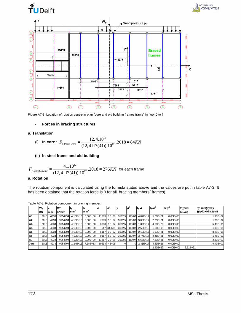
_____________________________________________________________________________ 172 MSc Thesis
Figure A7-8: Location of rotation centre in plan (core and old building frames frame) in floor 0 to 7
• Forces in bracing structures
a. Translation
(i) In core : 12
, , 12
12,4.10.2018 84
(12,4 7(41)).10y transl coreF KN= =+
(ii) In steel frame and old building
12
, , 12
41.10.2018 276
(12,4 7(41)).10y transl frameF KN= =+
for each frame
a. Rotation The rotation component is calculated using the formula stated above and the values are put in table A7-3. It has been obtained that the rotation force is 0 for all bracing members( frames).
Table A7-3: Rotation component in bracing member:
Wy e MT Iy Ix xi xi 2 yi yi 2 Iy.xi Iy.xi 2 Ix.yi 2 ΣΣΣΣ(Iyxi2+ Fy; rot= (Ι(Ι(Ι(Ι y.xi)/
KN mm KNmm mm 4 mm 4Ixi.yi2) ΣΣΣΣ(Iyxi2+Ixi.yi2))MT
W1 2018 4933 9954794 4,10E+13 0,00E+00 11883 1E+08 3192,5 1E+07 4,87E+17 5,79E+21 0,00E+00 1,93E+02
W2 2018 4933 9954794 4,10E+13 0,00E+00 7383 5E+07 3192,5 1E+07 3,03E+17 2,23E+21 0,00E+00 1,20E+02
W3 2018 4933 9954794 4,10E+13 0,00E+00 3383 1E+07 3192,5 1E+07 1,39E+17 4,69E+20 0,00E+00 5,48E+01
W4 2018 4933 9954794 4,10E+13 0,00E+00 617 380689 3192,5 1E+07 2,53E+16 1,56E+19 0,00E+00 1,00E+01
W5 2018 4933 9954794 4,10E+13 0,00E+00 5117 3E+07 3192,5 1E+07 2,10E+17 1,07E+21 0,00E+00 8,29E+01
W6 2018 4933 9954794 4,10E+13 0,00E+00 9117 8E+07 3192,5 1E+07 3,74E+17 3,41E+21 0,00E+00 1,48E+02
W7 2018 4933 9954794 4,10E+13 0,00E+00 13617 2E+08 3192,5 1E+07 5,58E+17 7,60E+21 0,00E+00 2,21E+02
Core 2018 4933 9954794 1,24E+13 7,68E+13 19233 4E+08 0 0 2,38E+17 4,59E+21 0,00E+00 9,43E+01
2,52E+22 0,00E+00 2,52E+22

___________________________________________________________________________________ L. UWIMANA 173
Table A7-4: Forces acting on bracing members
Upper
Translation Rotation Total force Height UDLKN KN KN m KN/m
W5 1137 48 1185 26,64 44Core 881 48 929 26,64 35
Lower
Translation Rotation Total force Height UDLKN KN KN m N/m
W1 276 193 469 20.56 23W2 276 120 396 20.56 19W3 276 55 331 20.56 16W4 276 10 286 20.56 14W5 276 83 359 20.56 17W6 276 148 424 20.56 21W7 276 221 497 20.56 24
Core 84 94 178 20.56 9
A7.4 Concrete core with old building and three brac ed steel frames
For 3 frames, there is change in the upper part only because the lower part is the same as the previous case
A7.4.1 Upper part
• Location of rotation center
( )12 12 18,
112 12
,1
.12, 4.10 .4250 16.10 ( 11600 20100 28600) 1, 0175.10
1684612, 4 3(16) .10 60, 4.10
n
y i ii
c cn
y ii
I xx x mm
I
=
=
+ + + += ⇒ = = =+
∑
∑
,1
,1
.0
n
x i ii
c cn
x ii
I yy y
I
=
=
= ⇒ =∑
∑
FigureA7-9: Location of rotation centre in plan(core and three frames) in floor 7 to 15

_____________________________________________________________________________ 174 MSc Thesis
• Forces in bracing structures The bracing structures are subjected to translation and rotation. Each component is calculated and summed up to get the total force acting on bracing structure.
,, .;
,1
.y iy transl i yn
y ii
IF W
I=
=∑
and
( ),
, ,2 2
, ,1
..
. .
y i iy rotation i Tn
y i i x i ii
I xF M
I x I y=
+∑
a. Translation
(i) In core
12
, , 12
12,4.10.2018 414
(12,4 3(16)).10y transl coreF KN= =+
(ii) In steel frame
12
, , 12
16.10.2018 535
(12,4 3(16)).10y transl frameF KN= =+
a. Rotation
Table A7-5: Calculation of rotation forces
Wy e MT Iy Ix xi xi 2 yi yi 2 Iy.xi Iy.xi 2 Ix.yi 2 ΣΣΣΣ(Iyxi2+ Fy; rot= (Ι(Ι(Ι(Ι y.xi)/
KN mm KNmm mm 4 mm 4Ixi.yi2) ΣΣΣΣ(Iyxi2+Ixi.yi2))MT
W1 2018 1704 3438672 1.60E+13 0.00E+00 5246 3E+07 3192.5 1E+07 8.39E+16 4.40E+20 0.00E+00 6.03E+01
W3 2018 1704 3438672 1.60E+13 0.00E+00 3254 1E+07 3192.5 1E+07 5.21E+16 1.69E+20 0.00E+00 3.74E+01
W5 2018 1704 3438672 1.60E+13 0.00E+00 11754 1E+08 3192.5 1E+07 1.88E+17 2.21E+21 0.00E+00 1.35E+02
Core 2018 1704 3438672 1.24E+13 7.68E+13 12596 2E+08 0 0 1.56E+17 1.97E+21 0.00E+00 1.12E+02
4.79E+21 0.00E+00 4.79E+21
Table A7-6: Total forces acting on bracing members
Upper Translation Rotation Total force Height UDLKN KN KN m N/m
W1 535 60 595 26,64 22W3 535 37 572 26,64 21W5 535 135 670 26,64 25
Core 414 112 526 26,64 20
A7.3.2 Lower part
The characteristics of the lower part is the same as what obtained in previous option (see A7.2.2)
Translation Rotation Total force Height UDLKN KN KN m N/m
W1 276 193 469 20.56 23W2 276 120 396 20.56 19W3 276 55 331 20.56 16W4 276 10 286 20.56 14W5 276 83 359 20.56 17W6 276 148 424 20.56 21W7 276 221 497 20.56 24
Core 84 94 178 20.56 9

___________________________________________________________________________________ L. UWIMANA 175
A7.5 Conclusion
To stabilize the whole building using only the concrete core will not be possible, the method results in excessive deflection due to translation and rotation since the core in eccentrically placed in plan. The existing building can help the new structure to restrain the lateral loads when the two structures are would be laterally connected up to 7th floor. From 7th floor upwards, the core could act alone, but it has obtained that it would deflect more because it is not stiff enough in lateral direction to take all lateral loads acting on the whole building. Furthermore minimize the deflection, a steel frame can be put to act in parallel with concrete core. It has been decided to put a braced frame in axis 5 due to non obstruction benefits. But the frame is taking too much load that is why 2 additional frames can be proposed in axis 1 and 3 to help 5. The construction of cantilever near the core is very challenging, but if concrete walls would be constructed in axis -1 and 0, the lateral stiffness increases and floor up wards, it is easy to construct cantilevers by extending the wall at every floor level.

_____________________________________________________________________________ 176 MSc Thesis

___________________________________________________________________________________ L. UWIMANA 177
A8. DESIGN OF BRACINGS IN THE FINAL DESIGN The bracing members are loaded mainly by the lateral force acting to the entire structure and a part of vertical load since braces prevent columns from horizontal deflection and buckling. For simplicity, it’s suggested to use cross bracing in the upper part of the building because cross bracing are loaded in tension but they have to be checked for buckling since lateral load can reverse and loading the bracing member in compression. In addition to this, they also carry some parts of the vertical loads. From Chapter 9 and Appendix 7, the best way of stabilizing the building is by using concrete walls in axes -1 and 0 plus 3- braced frame in axes 1, 3 and 5. The frame in axis 5 is governing; the horizontal loads acting on it are 25 and 17 KN/m respectively on upper and lower parts. The dead load and live load are resprectively 30,4 and 7,4 KN/m.
FigureA8- 1: Bracing pattern and lateral load in braced frame 5
Bracing members can be sized by using ultimate load acting on structure.
Table A8-1: Used load combination
1 2 3 4 PC LC SLS SLS ULS ULS Self weight 1,0 1,0 1,2 1,2
Variable load 1,0 1,0 1,5 1,5 Lateral load from East 1,0 1,5
Lateral load from west
1,0 1,5
The ultimate shear force in foundation of the structure is as follow:
1 1 2 2. . . . 1,5.17.20,56 1,5.25.26,64 1523BottomV w h w h KNγ γ= + ⇒ + =
• The lower part of the building is braced by the old building; the connectors between old and new building
transmit lateral loads to the bracing structure (old building). These connector can be sized based on shear force to be transmitted to the old building( bracing system) The minimum area of steel required is
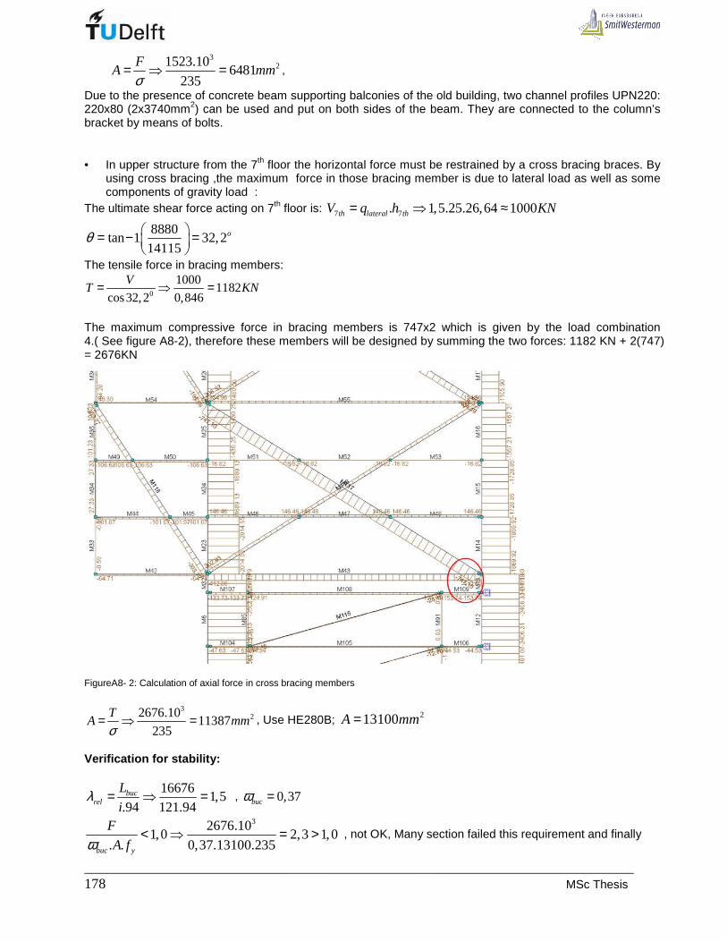
_____________________________________________________________________________ 178 MSc Thesis
3
21523.106481
235
FA mm
σ= ⇒ = ,
Due to the presence of concrete beam supporting balconies of the old building, two channel profiles UPN220: 220x80 (2x3740mm2) can be used and put on both sides of the beam. They are connected to the column’s bracket by means of bolts. • In upper structure from the 7th floor the horizontal force must be restrained by a cross bracing braces. By
using cross bracing ,the maximum force in those bracing member is due to lateral load as well as some components of gravity load :
The ultimate shear force acting on 7th floor is: 7 7. 1,5.25.26,64 1000th lateral thV q h KN= ⇒ ≈
8880tan 1 32,2
14115oθ = − =
The tensile force in bracing members:
0
10001182
cos32,2 0,846
VT KN= ⇒ =
The maximum compressive force in bracing members is 747x2 which is given by the load combination 4.( See figure A8-2), therefore these members will be designed by summing the two forces: 1182 KN + 2(747) = 2676KN
FigureA8- 2: Calculation of axial force in cross bracing members
322676.10
11387235
TA mm
σ= ⇒ = , Use HE280B; 213100A mm=
Verification for stability:
166761,5
.94 121.94buc
rel
L
iλ = ⇒ = , 0,37bucω =
32676.101,0 2,3 1,0
. . 0,37.13100.235buc y
F
A fω< ⇒ = > , not OK, Many section failed this requirement and finally

___________________________________________________________________________________ L. UWIMANA 179
HE400B was tried
219800A mm= 16676
1,0.94 171.94
bucrel
L
iλ = ⇒ = , 0,6bucω =
32676.101,0 0,85 1,0
. . 0,67.19800.235buc y
F
A fω< ⇒ = < OK
The frame restraining lateral loads is likely to have more deflection on cantilevers, therefore 3-storey braces in cantilevers can help to convey facade and some beam load to the supporting column. The maximum axial force in these bracings is given by load combination 3 (Figure A8-3) is 360.2= 720 KN
FigureA8- 3: Calculation of axial force in cantilever bracing
32720.10
3064235
FA mm
σ= ⇒ = , Use HE200 B
Verification for stability: 10600
1,3.94 85,4.94
bucrel
L
iλ = ⇒ = , 0,47bucω =
3720.101,0 0,83 1,0
. . 0,47.7810.235buc y
F
A fω< ⇒ = < , OK

_____________________________________________________________________________ 180 MSc Thesis
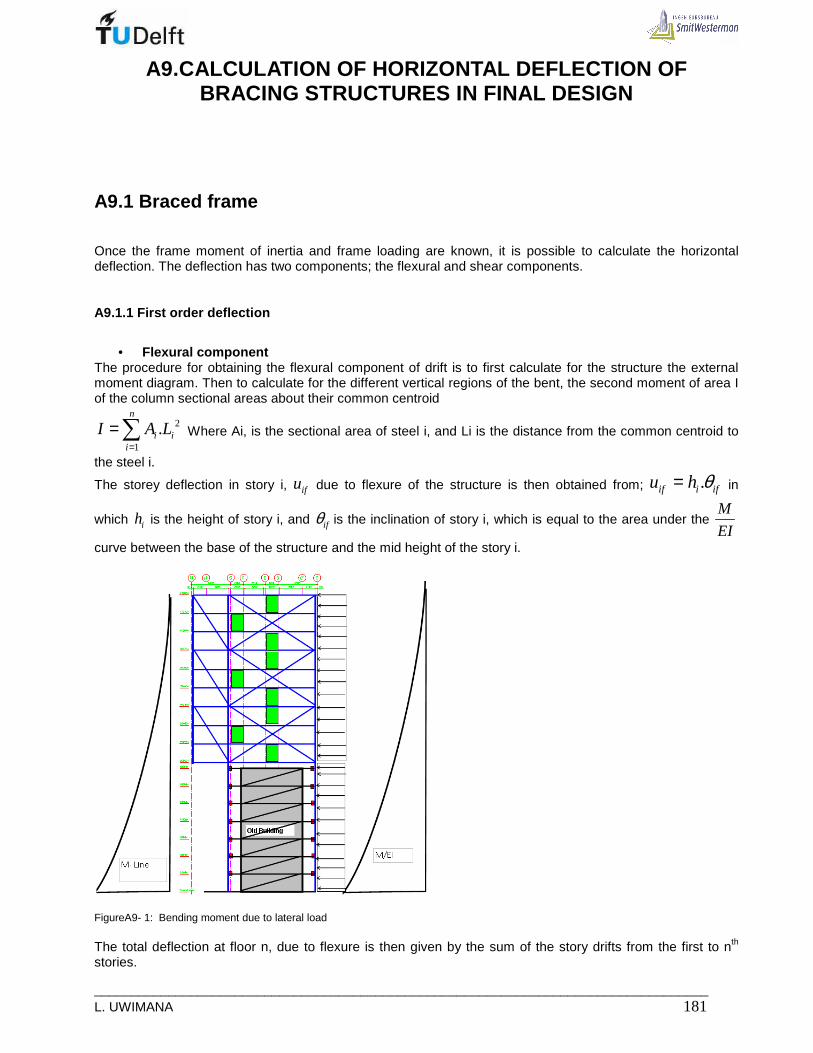
___________________________________________________________________________________ L. UWIMANA 181
A9.CALCULATION OF HORIZONTAL DEFLECTION OF BRACING STRUCTURES IN FINAL DESIGN
A9.1 Braced frame
Once the frame moment of inertia and frame loading are known, it is possible to calculate the horizontal deflection. The deflection has two components; the flexural and shear components.
A9.1.1 First order deflection
• Flexural component
The procedure for obtaining the flexural component of drift is to first calculate for the structure the external moment diagram. Then to calculate for the different vertical regions of the bent, the second moment of area I of the column sectional areas about their common centroid
2
1
.n
i ii
I A L=
=∑ Where Ai, is the sectional area of steel i, and Li is the distance from the common centroid to
the steel i.
The storey deflection in story i, ifu due to flexure of the structure is then obtained from; .if i ifu h θ= in
which ih is the height of story i, and ifθ is the inclination of story i, which is equal to the area under the M
EI
curve between the base of the structure and the mid height of the story i.
FigureA9- 1: Bending moment due to lateral load The total deflection at floor n, due to flexure is then given by the sum of the story drifts from the first to nth stories.

_____________________________________________________________________________ 182 MSc Thesis
,1
n
f tot ifi
u u=
=∑
Calculation procedures: 6. Compute the moment of inertia of the column sectional area about their common centroid. The part
contributing to the lateral load resistance is the one starting from the ground. It includes 2-support columns from the ground level to the 15th floor.
This values is put in table 12-3 column 7. Compute the value of the external moment at each story and enter the value in column 6. 7. Determine for each story the value of hM/EI, and enter the results in column 9. 8. Determine for each story i, the accumulation of . ifu θ from the ground level up to and including story i,
ifθ and record it in column10. Such accumulated values give the inclination of each story i due to
flexure ifθ .
9. Record the product of ih and ifθ in column 11. .i ifh θ is the drift in story i, ifu , due to flexure.
10. At each level, the value of the lateral drift is required, evaluate the accumulation of the story
drift , ifu ,from the ground level up and considered n.th floor to give the drift totalu due to flexure. Enter
these in column 12. Table9- 1: Evaluation of flexural component of deflection for new building
Storey Cumul.storeyStory Story Cum.height Lateral External Frame Mod. Elast. Inclination inclinastion storey Cumul.
heigh Ground -roof load moment inertia E δθi=h*M/EI θif drift Drift
mm m KN/m Nm x1012mm4 x104N/mm 2rads Rads mm mm
Roof 2960 47200 16 2115 2960 44240 16 2114 2960 41280 16 2113 2960 38320 16 2112 2960 35360 16 2111 2960 32400 16 2110 2960 29440 16 21
9 2960 26480 16 218 2960 23520 16 217 2960 20560 16 21
Roof 6 2800 19600 27600 0 41 22,56 2800 16800 30400 2800 41 22,55 2800 14000 33200 5600 41 22,54 2800 11200 36000 8400 41 22,53 2800 8400 38800 11200 41 22,52 2800 5600 41600 14000 41 22,51 2800 2800 44400 16800 41 22,5
Ground 0 47200 19600 41 22,5floor
Cum. height roof-ground
m0
29605920888011840
26640
14800177602072023680
,1
n
s tot ifi
u u=
=∑
Calculation data

___________________________________________________________________________________ L. UWIMANA 183
The calculation data for steel braced frame are summarized in table A9-2. TableA9- 2: Calculation data
LBR (mm) 16676 10385
LB (mm) 14115 10000
AB (mm2) 2xHE 700M 76600 250x210 52500
ABR (mm2) HE400B 19800 650x336 218400
IB (mm4) HE550 2,73E+09 250x210 2,73E+08
EBR N/mm2) 210000 210000+15000 225000Frame inertia (mm4) 1,60E+13 16e12 + 25 e12 4,10E+13
Upper part Lower part
TableA9- 3: Flexural component of deflection when core and three braced frames are used for stability
Storey Cumul.storey
Story Story Cum.height Lateral External Frame Mod. Elast. Inclination inclinastion storey Cumul. heigh Ground -roof load moment inertia E δθi=h*M/EI θif drift Drift
mm m KN/m Nm x1012mm 4 x10⁴N/mm2rads Rads mm mm
Roof 2960 47200 25 0 16 21 0 6,14E-05 0,18 2,0015 2960 44240 25 1,1E+08 16 21 9,648E-08 6,14E-05 0,18 1,8214 2960 41280 25 4,4E+08 16 21 3,859E-07 6,13E-05 0,18 1,6413 2960 38320 25 9,9E+08 16 21 8,683E-07 6,09E-05 0,18 1,4612 2960 35360 25 1,8E+09 16 21 1,544E-06 6,01E-05 0,18 1,2811 2960 32400 25 2,7E+09 16 21 2,412E-06 5,85E-05 0,17 1,1010 2960 29440 25 3,9E+09 16 21 3,473E-06 5,61E-05 0,17 0,93
9 2960 26480 25 5,4E+09 16 21 4,728E-06 5,27E-05 0,16 0,768 2960 23520 25 7E+09 16 21 6,175E-06 4,79E-05 0,14 0,607 2960 20560 25 8,9E+09 16 21 7,815E-06 4,17E-05 0,12 0,46
Roof 6 2800 19600 27600 0 17 9,5E+09 41 22,5 2,887E-06 3,39E-05 0,00 0,346 2800 16800 30400 2800 17 1,1E+10 41 22,5 3,473E-06 3,10E-05 0,09 0,345 2800 14000 33200 5600 17 1,4E+10 41 22,5 4,1E-06 2,76E-05 0,08 0,254 2800 11200 36000 8400 17 1,6E+10 41 22,5 4,767E-06 2,35E-05 0,07 0,173 2800 8400 38800 11200 17 1,8E+10 41 22,5 5,474E-06 1,87E-05 0,05 0,112 2800 5600 41600 14000 17 2,1E+10 41 22,5 6,222E-06 1,32E-05 0,04 0,061 2800 2800 44400 16800 17 2,3E+10 41 22,5 7,011E-06 7,01E-06 0,02 0,02
Ground 0 47200 19600 17 2,6E+10 41 22,5 0 0,00E+00 0,00 0,00floor
Cum. height roof-ground
m
0
26640
14800177602072023680
296059208880
11840
, ,1
2n
f tot f ii
u u mm=
= =∑
• Shear component
The shear component of the story drift is story i, isu is a function of the external shear and the properties of
braces and girder in that story [6]. The shear component of the total drift at floor level n, ,s totalu is equal to
the sum of the story shear component of the drift from the ground to nth stories, that is
,1
n
s tot isi
u u=
=∑

_____________________________________________________________________________ 184 MSc Thesis
FigureA9- 2: Steel frame and lateral loads The top part has cross bracing, the lower part as it braces the new building, it is modelled as frame with single braced bracing. The horizontal displacement for both cases is given by these relations:
3
0 7 2.BR B
B BR B
L LVu
E L A A−
= +
(Equivalent single diagonal of in-fill) and
3
7 15 22 .BR
B BR
LVu
E L A−
=
(Cross bracing)
in the upper section of the building LBR and ABR are respectively is the length and the area of the bracing L is the length of girder E is modulus of elasticity. V: The shear force LB and AB are respectively is the length and the area of the upper beam
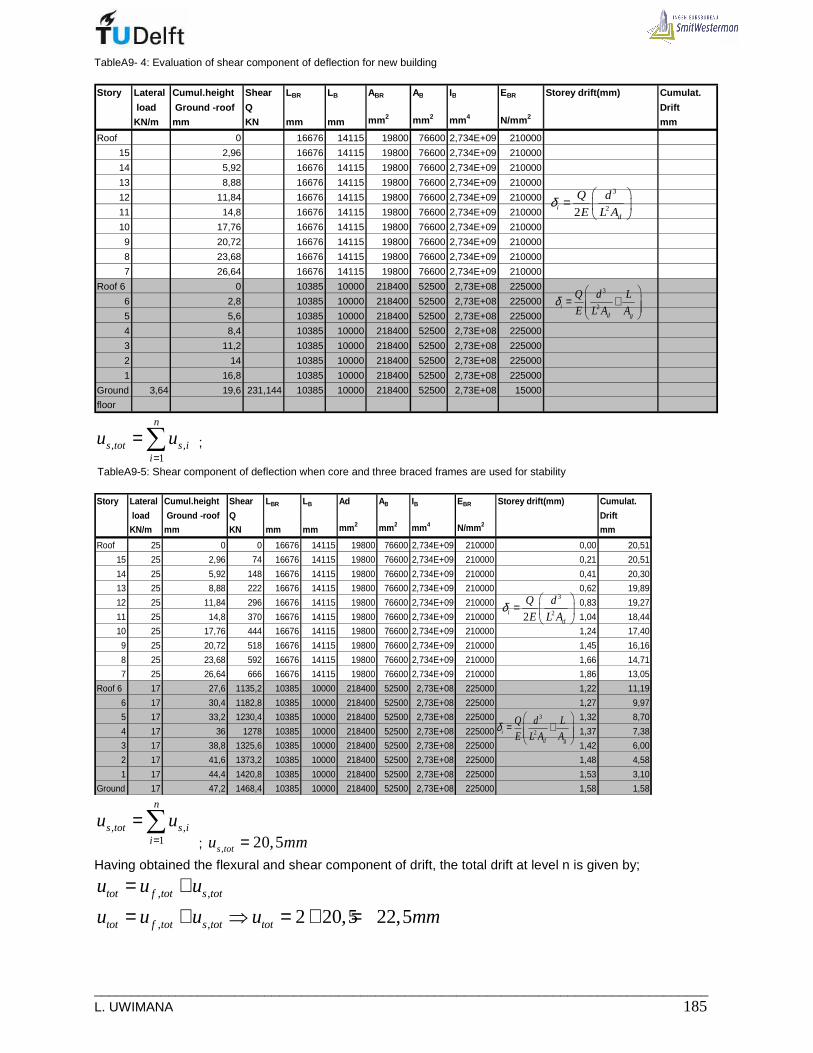
___________________________________________________________________________________ L. UWIMANA 185
TableA9- 4: Evaluation of shear component of deflection for new building Story Lateral Cumul.height Shear L BR LB ABR AB IB EBR Storey drift(mm) Cumulat.
load Ground -roof Q Drift
KN/m mm KN mm mm mm 2 mm 2 mm 4 N/mm 2mm
Roof 0 16676 14115 19800 76600 2,734E+09 210000
15 2,96 16676 14115 19800 76600 2,734E+09 210000
14 5,92 16676 14115 19800 76600 2,734E+09 210000
13 8,88 16676 14115 19800 76600 2,734E+09 210000
12 11,84 16676 14115 19800 76600 2,734E+09 210000
11 14,8 16676 14115 19800 76600 2,734E+09 210000
10 17,76 16676 14115 19800 76600 2,734E+09 210000
9 20,72 16676 14115 19800 76600 2,734E+09 210000
8 23,68 16676 14115 19800 76600 2,734E+09 210000
7 26,64 16676 14115 19800 76600 2,734E+09 210000
Roof 6 0 10385 10000 218400 52500 2,73E+08 225000
6 2,8 10385 10000 218400 52500 2,73E+08 225000
5 5,6 10385 10000 218400 52500 2,73E+08 225000
4 8,4 10385 10000 218400 52500 2,73E+08 225000
3 11,2 10385 10000 218400 52500 2,73E+08 225000
2 14 10385 10000 218400 52500 2,73E+08 225000
1 16,8 10385 10000 218400 52500 2,73E+08 225000
Ground 3,64 19,6 231,144 10385 10000 218400 52500 2,73E+08 15000
floor
3
22id
Q d
E L Aδ
=
3
2id g
Q d L
E L A Aδ
= +
, ,1
n
s tot s ii
u u=
=∑ ;
TableA9-5: Shear component of deflection when core and three braced frames are used for stability Story Lateral Cumul.height Shear L BR LB Ad AB IB EBR Storey drift(mm) Cumulat.
load Ground -roof Q Drift
KN/m mm KN mm mm mm 2 mm 2 mm 4 N/mm2mm
Roof 25 0 0 16676 14115 19800 76600 2,734E+09 210000 0,00 20,51
15 25 2,96 74 16676 14115 19800 76600 2,734E+09 210000 0,21 20,51
14 25 5,92 148 16676 14115 19800 76600 2,734E+09 210000 0,41 20,30
13 25 8,88 222 16676 14115 19800 76600 2,734E+09 210000 0,62 19,89
12 25 11,84 296 16676 14115 19800 76600 2,734E+09 210000 0,83 19,27
11 25 14,8 370 16676 14115 19800 76600 2,734E+09 210000 1,04 18,44
10 25 17,76 444 16676 14115 19800 76600 2,734E+09 210000 1,24 17,40
9 25 20,72 518 16676 14115 19800 76600 2,734E+09 210000 1,45 16,16
8 25 23,68 592 16676 14115 19800 76600 2,734E+09 210000 1,66 14,71
7 25 26,64 666 16676 14115 19800 76600 2,734E+09 210000 1,86 13,05
Roof 6 17 27,6 1135,2 10385 10000 218400 52500 2,73E+08 225000 1,22 11,19
6 17 30,4 1182,8 10385 10000 218400 52500 2,73E+08 225000 1,27 9,97
5 17 33,2 1230,4 10385 10000 218400 52500 2,73E+08 225000 1,32 8,70
4 17 36 1278 10385 10000 218400 52500 2,73E+08 225000 1,37 7,38
3 17 38,8 1325,6 10385 10000 218400 52500 2,73E+08 225000 1,42 6,00
2 17 41,6 1373,2 10385 10000 218400 52500 2,73E+08 225000 1,48 4,58
1 17 44,4 1420,8 10385 10000 218400 52500 2,73E+08 225000 1,53 3,10
Ground 17 47,2 1468,4 10385 10000 218400 52500 2,73E+08 225000 1,58 1,58
3
22id
Q d
E L Aδ
=
3
2id g
Q d L
E L A Aδ
= +
, ,1
n
s tot s ii
u u=
=∑ ; , 20,5s totu mm=
Having obtained the flexural and shear component of drift, the total drift at level n is given by;
, ,tot f tot s totu u u= +
, , 2 20,5 22,5tot f tot s tot totu u u u mm= + ⇒ = + =

_____________________________________________________________________________ 186 MSc Thesis
A8.1.2 Second order effect
Buckling load of the frame The braced frame is assumed to be partially restrained, therefore:
2
1; 20
.E frame
EIP
L
π= 1,12oL L= for a building of more than 5 stories
The frame is made of two supporting composite columns and bracing. The member properties are shown in the following table.
# E[N/mm2] A[mm2] r[mm] r2 I mm4 EI[Nmm2]
G Steel CHS457x16 2.10E+05 2.22E+04 3.87E+03 1.49E+07 3.32E+11 6.96E+16
Concrete B45 3.60E+04 1.39E+05 3.87E+03 1.49E+07 2.08E+12 7.47E+16
R-bars 10Ф20 3.14E+03 2.95E+03 3.87E+03 1.49E+07 4.40E+10 1.38E+14
C Steel CHS406,4x8 2.10E+05 1.00E+04 1.03E+04 1.05E+08 1.05E+12 2.21E+17
Concrete B45 3.60E+04 1.17E+05 1.03E+04 1.05E+08 1.23E+13 4.43E+17
R-bars 8Ф20 2.10E+05 2.51E+03 1.03E+04 1.05E+08 2.64E+11 5.54E+16
Sum 1.61E+13 8.64E+17
( )2 16
81; 2
.86,4.1030,5.10
1,12.47200E frameP KN
π= =
2EP = 0,5
C
L
1 2
1 1 1
E E EP P P= +
2; 0,5E core
CP
L= , where C is the foundation spring constant
Determination of foundation spring constant Data:
• Number of piles in one frame: 10 piles of 15 m long 15pL m= , 380mmφ =
2
2.380113354
4pA mmπ= =
Material: Concrete B45
FigureA9-3: Braced frame and its simplified model

___________________________________________________________________________________ L. UWIMANA 187
FigureA9-4: Braced frame and its foundation
• Loads :
Vertical loads :
( )
( )
21
2
2
7,14 / . 4,25 .19,9 604
2 / .2.4,25 17
1,75 / . 4,25 .19,9 148
769 .10 7690
DL KN m m m KN
DL KN m KN
LL KN m m m KN
KN floors KN
= == =
= =Σ = =
• Lateral moment in foundation 2 2
1 1 2; ; , 2 2
. 17.20,56 26,64. 25.26,64 47,2 26157
2 2 2 2s d foot x
w h hM w h H KNm = + − ⇒ + − =
• Moment due to the eccentricity:
; ; . 7690.3,2 24608s d eccM P e KNm= ⇒ =
• Total moment at the base is ; ; , ; ; 26157 24608 50765s d foot x s d eccMtotal M M KNm= + ⇒ + =
• Pile moment of inertia: 2
1
.n
p ii
I n e=
=∑ where n = number of pile in a row , ie = eccentricity of pile i,
from the application point of the vertical load;
2 2 2 2 2 8 4(2.8057,5 3.7057,5 2.6057,5 1.6557,5 2.7557,5 ) 5,1.10pI mm= + + + + =
. /np
MP e n
I
=
, with “n”, the number of piles with the same distance from centroidal axis
6
8
50765.10.8057,5 / 2 401
5,1.10nP KN
= =
• Elastic deformation of a pile is as follow: .1,5.
.n p
p p
P lL
E A∆ =
3401.10 .1,5.150002,2
36000.113354L mm∆ = =
Then the rotation angle 2,2
8057,5
L
eϕ ϕ∆= ⇒ = and 656765.8057,5
208.10 /2,2
MC C KNm rad
ϕ= ⇒ = =
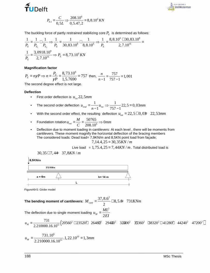
_____________________________________________________________________________ 188 MSc Thesis
6
62
208.108,8.10
0,5 0,5.47,2E
CP KN
L= ⇒ =
The buckling force of partly restrained stabilizing core EP is determined as follows:
1 2
6 8
8 6 16
96
16
1 1 1 1 1 1 1 8,8.10 30,83.10
30,83.10 8,8.10 2,7.10
1 3,0918.108,73.10
2,7.10
E E E E E
EE
P P P P P
P KNP
+= + ⇒ = + ⇒ = =
= ⇒ =
Magnification factor
68,73.10757
1,5.7690E
E
PP n P n
Pγ
γ= ⇒ = = = then,
7571,001
1 757 1
n
n= =
− −
The second degree effect is not large. Deflection
• First order deflection is 1 22,5stu mm
• The second order deflection 2 1
1 122,5 0,03
1 757 1nd stu u mmn
= ⇒ =− −
• With the second order effect, the resulting deflection 22,5 0,03 22,53totu mm= + =
• Foundation rotation6
507650
208.10rot
Mu mm
C= = ⇒
• Deflection due to moment loading in cantilevers: At each level , there will be moments from cantilevers. These moment magnify the horizontal deflection of the bracing members The considered loads: Dead load= 7,9KN/m and 8,5KN point load from façade; 7,14.4,25 30,35 /KN m=
Live load = 1,75.4,25 7,44 /KN m= . Total distributed load is
30,35 7,44 37,8 /KN m+ =
FigureA9-5: Girder model
The bending moment of cantilevers: 237,8.6
8,5.6 7312cantM KNm= + =
The deflection due to single moment loading 2
2M
MLu
EI=
( )2 2 2 2 2 2 2 2 2 212
73120560 23520 26480 29440 32400 35360 38320 4128044240 47200
2.210000.16.10Mu = + + + + + + + + +
6
1012
731.10.1,22.10 1,3
2.210000.16.10Mu mm= =
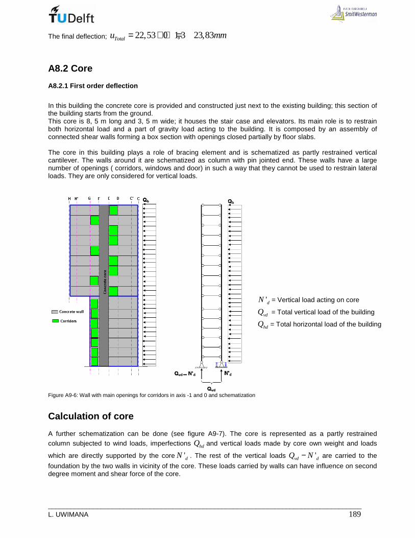
___________________________________________________________________________________ L. UWIMANA 189
The final deflection; 22,53 0 1,3 23,83Totalu mm= + + =
A8.2 Core
A8.2.1 First order deflection
In this building the concrete core is provided and constructed just next to the existing building; this section of the building starts from the ground. This core is 8, 5 m long and 3, 5 m wide; it houses the stair case and elevators. Its main role is to restrain both horizontal load and a part of gravity load acting to the building. It is composed by an assembly of connected shear walls forming a box section with openings closed partially by floor slabs. The core in this building plays a role of bracing element and is schematized as partly restrained vertical cantilever. The walls around it are schematized as column with pin jointed end. These walls have a large number of openings ( corridors, windows and door) in such a way that they cannot be used to restrain lateral loads. They are only considered for vertical loads.
Figure A9-6: Wall with main openings for corridors in axis -1 and 0 and schematization
Calculation of core
A further schematization can be done (see figure A9-7). The core is represented as a partly restrained column subjected to wind loads, imperfections hdQ and vertical loads made by core own weight and loads
which are directly supported by the core 'dN . The rest of the vertical loads 'vd dQ N− are carried to the
foundation by the two walls in vicinity of the core. These loads carried by walls can have influence on second degree moment and shear force of the core.
'dN = Vertical load acting on core
vdQ = Total vertical load of the building
hdQ = Total horizontal load of the building
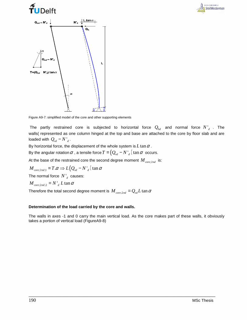
_____________________________________________________________________________ 190 MSc Thesis
Figure A9-7: simplified model of the core and other supporting elements The partly restrained core is subjected to horizontal force hdQ and normal force 'dN . The
walls( represented as one column hinged at the top and base are attached to the core by floor slab and are loaded with 'vd dQ N− .
By horizontal force, the displacement of the whole system is tanL α .
By the angular rotationα , a tensile force ( )' tanvd dT Q N α= − occurs.
At the base of the restrained core the second degree moment ;2core ndM is:
( );2 ;1 . ' tancore nd vd dM T L Q Nα α= ⇒ −
The normal force 'dN causes:
;2 ;2 ' tancore nd dM N L α=
Therefore the total second degree moment is ;2 tancore nd vdM Q L α=
Determination of the load carried by the core and w alls. The walls in axes -1 and 0 carry the main vertical load. As the core makes part of these walls, it obviously takes a portion of vertical load (FigureA9-8)

___________________________________________________________________________________ L. UWIMANA 191
Figure A9-8: Floor plan 7 to 15 floor Section in axis -1 or 0 (i). wall -1:
• Self weight of wall and cantilever
Total wall area: 214,115.47,2 666m=
Openings: ( ) ( ) ( ) ( ){ } 21,62.1,225 1,82.2,185 2,02.1,225 1,795.1,875 .16 189m+ + + =
Net area: 2666 189 477m− =
Design load from wall self weight: ( ) ( ). . 477.0,250.24 2862net wall concreteA t KNγ ⇒ =
Cantilever: Total wall area: 25,785.26,64 154m=
Openings: ( ) ( ){ } 21,96.1,875 2,02.1,225 .9 55,3m+ =
Net area: 2154 55,3 99m− =
Design load from wall self weight: ( ) ( ). . 99.0,250.24 475net wall concreteA t KNγ ⇒ =
• Load from floors:
[ ]{ }( )( )
(7,9 1,75) 16(4,25.14,115
floors DL VL floors
floors
F q q A
F
= +
= +
9262floorsF KN=
Cantilever:
[ ]
( )( )
(7,9 1,75) 10(4,25.5,785
floors DL VL floors
floors
F q q A
F
= +
= +

_____________________________________________________________________________ 192 MSc Thesis
2373floorsF KN=
• Load from staircase
( )( )
4,74(3,7 2) 16 .3,1
2
stair DL VL stair
floors
F q q A
F
= +
= +
670stairF KN= , a half goes to wall -1
Total load: ; 1 2862 475 9262 2373 335 15307TotalF KN− = + + + + =
The load supported by the core is: 1; 1
1
15307. .3,5 3796
14,115total
Core coretotal
F KNF L KN
L−
−−
= ⇒ =
ii).Wall 0
• Self weight of wall 0 and its cantilever:
Total wall area: 214,115.47,2 666m= Openings:
( ) ( ) ( ) ( ) ( ){ }2
9 2,230.2,68 2 1,100.1,280 9 1,795.1,100 7 1,795.2,460 2,52(2,1 2 2,01
79,13 17,8 31 15,4 143,3m
+ + + + + +
+ + + =
Net area: 2666 143,3 523m− = Design load from wall self weight:
( ) ( ). . 545.0,250.24 3270net wall concreteA t KNγ ⇒ =
Total wall area of cantilever: 25,785.26,64 154m=
Openings: ( ) ( ){ } 22.1,28 1,1.2,46 .9 47,4m+ =
Net area: 2154 47,4 107m− =
Design load from cantilever wall self weight: ( ) ( ). . 107.0,250.24 513net wall concreteA t KNγ ⇒ =
• Load from floors :
[ ]( )( )
(7,9 1,75) 16(5,8.14,115
floors DL VL floors
floors
F q q A
F
= +
= +
12640floorsF KN=
Cantilever floor:
[ ]
( )( )
(7,9 1,75) 10(5,8.5,785
floors DL VL floors
floors
F q q A
F
= +
= +
3238floorsF KN=
Total load: ;0 3270 513 12640 3238 19661TotalF KN= + + + =
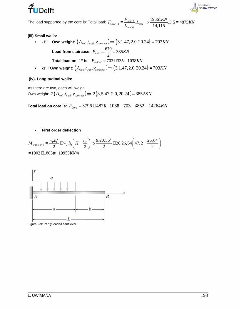
___________________________________________________________________________________ L. UWIMANA 193
The load supported by the core is: Total load: 1; 1
1
19661. .3,5 4875
14,115total
Core coretotal
F KNF L KN
L−
−−
= ⇒ =
(iii) Small walls:
• -1’: Own weight : ( ) ( ). . 3,1.47,2.0,20.24 703wall wall concreteA t KNγ ⇒ =
Load from staircase: 670
3352stairF KN= =
Total load on -1” is : 1' 703 335 1038wallF KN− = + =
• -1’’: Own weight : ( ) ( ). . 3,1.47,2.0,20.24 703wall wall concreteA t KNγ ⇒ =
(iv). Longitudinal walls: As there are two, each will weigh
Own weight: ( ) ( )2 . . 2 8,5.47,2.0,20.24 3852wall wall concreteA t KNγ ⇒ =
Total load on core is: 3796 4875 1038 703 3852 14264CoreF KN= + + + + =
• First order deflection
2 21 1 2
; ; , 2 2
. 9.20,56 26,64. 20.26,64 47,2
2 2 2 2
1902 18051 19953
s d foot x
w h hM w h H
KNm
= + − ⇒ + −
= + =
Figure 9-9: Partly loaded cantilever
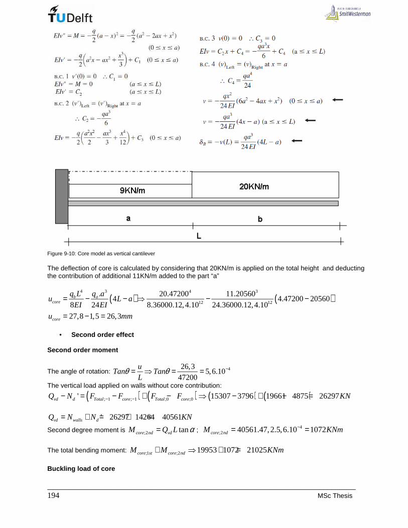
_____________________________________________________________________________ 194 MSc Thesis
Figure 9-10: Core model as vertical cantilever The deflection of core is calculated by considering that 20KN/m is applied on the total height and deducting the contribution of additional 11KN/m added to the part “a”
( ) ( )4 3 4 3
12 12
. 20.47200 11.205604 4.47200 20560
8 24 8.36000.12,4.10 24.36000.12,4.10
27,8 1,5 26,3
b acore
core
q L q au L a
EI EI
u mm
= − − ⇒ − −
= − =
• Second order effect
Second order moment
The angle of rotation: 426,35,6.10
47200
uTan Tan
Lθ θ −= ⇒ = =
The vertical load applied on walls without core contribution:
( ) ( ) ( ) ( ); 1 ; 1 ;0 ;0' 15307 3796 19661 4875 26297vd d Total core Total coreQ N F F F F KN− −− = − + − ⇒ − + − =
' 26297 14264 40561vd walls dQ N N KN= + = + =
Second degree moment is ;2 tancore nd vdM Q L α= ; 4;2 40561.47,2.5,6.10 1072core ndM KNm−= =
The total bending moment: ;1 ;2 19953 1072 21025core st core ndM M KNm+ ⇒ + =
Buckling load of core
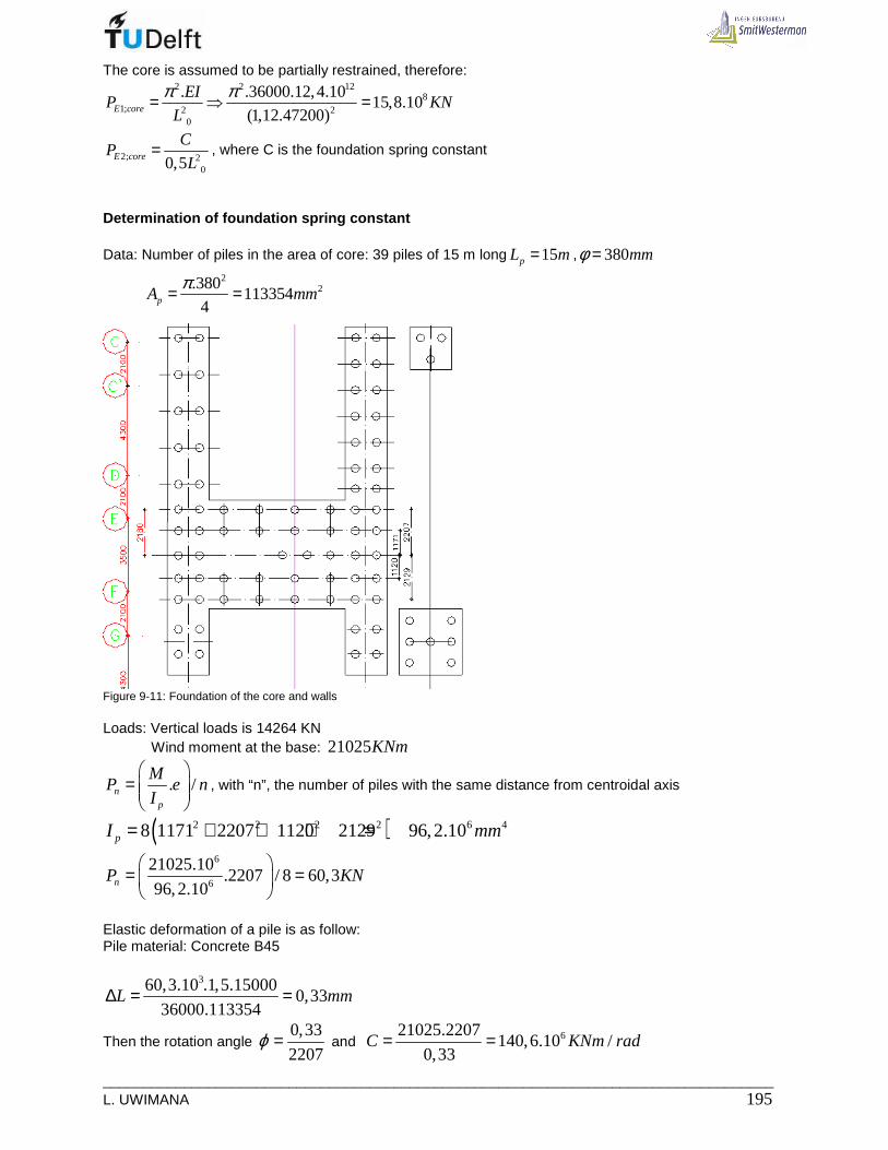
___________________________________________________________________________________ L. UWIMANA 195
The core is assumed to be partially restrained, therefore: 2 2 12
81; 2 2
0
. .36000.12,4.1015,8.10
(1,12.47200)E core
EIP KN
L
π π= ⇒ =
2; 200,5E core
CP
L= , where C is the foundation spring constant
Determination of foundation spring constant Data: Number of piles in the area of core: 39 piles of 15 m long 15pL m= , 380mmφ =
2
2.380113354
4pA mmπ= =
Figure 9-11: Foundation of the core and walls Loads: Vertical loads is 14264 KN Wind moment at the base: 21025KNm
. /np
MP e n
I
=
, with “n”, the number of piles with the same distance from centroidal axis
( )2 2 2 2 6 48 1171 2207 1120 2129 96,2.10pI mm= + + + =
6
6
21025.10.2207 / 8 60,3
96,2.10nP KN
= =
Elastic deformation of a pile is as follow: Pile material: Concrete B45
360,3.10 .1,5.150000,33
36000.113354L mm∆ = =
Then the rotation angle 0,33
2207ϕ = and 621025.2207
140,6.10 /0,33
C KNm rad= =

_____________________________________________________________________________ 196 MSc Thesis
6
62
140,6.105,95.10
0,5 0,5.47,2E
CP KN
L= ⇒ =
The buckling force of partly restrained stabilizing core EP is determined as follows:
1 2
6 8 9
8 6 15 15
96
15
1 1 1 1 1 1 1 5,95.10 15,8.10 1,586.10
15,8.10 5,95.10 9,401.10 9,401.10
1 1,586.105,93.10
9,401.10
E E E E E
EE
P P P P P
P KNP
+= + ⇒ = + ⇒ = =
= ⇒ =
Magnification factor
65,93.10280
1,5.14125E
E
PP n P n
Pγ
γ= ⇒ = = = then,
2801,004
1 280 1
n
n= =
− −
The second degree effect is not large. Deflection
• First order deflection is 1 26,3stu mm
• The second order deflection 2 1
1 126,3 0,1
1 280 1nd stu u mmn
= ⇒ =− −
• With the second order effect, the resulting deflection 26,3 0,1 26,4totu mm= + =
• Foundation rotation2
6
199530
2 140,6.10rot
qHu mm
C= = ⇒
• Deflection due to moment loading in cantilevers: At each level , there will be moments from cantilevers. These moment magnify the horizontal deflection of the bracing members The considered loads: Dead load= 7,9.4,25 33,6 /KN m= and 8,5KN point load from façade
Live load = 1,75.4,25 7,44 /KN m= . Total distributed load is 33,6 7,44 41 /KN m+ =
Figure 9-12: Girder model
The bending moment of cantilevers: 241.6
8,5.6 7892cantM KNm= + =
The deflection due to single moment loading 2
2M
MLu
EI=
( )2 2 2 2 2 2 2 2 2 212
78920560 23520 26480 29440 32400 35360 38320 4128044240 47200
2.36000.12,4.10Mu = + + + + + + + + +
1012
789.1,22.10 10,8
2.36000.12,4.10Mu mm= =
The final deflection; 26,3 0,1 0 10,8 37,1Totalu mm= + + + =
Stresses in core foot

___________________________________________________________________________________ L. UWIMANA 197
;foot
core footcore
MP
A Wσ = ± ,
128 312,4.10
75,2.101/ 2 1650
coreIW W mm
b= ⇒ = =
From Appendix 7, 26717500coreA mm= 3 6
; 8
2;
2;
14264.10 21025.102,1 2,8
6717500 75,2.10
0,7 /
4,9 /
core foot
core foot
core foot
N mm
N mm
σ
σ
σ
= − ± ⇒ − ±
=
= −
With concrete grade B45 23,8 /ctmf N mm= and 253 /cmf N mm= ; the core is then safe.

_____________________________________________________________________________ 198 MSc Thesis
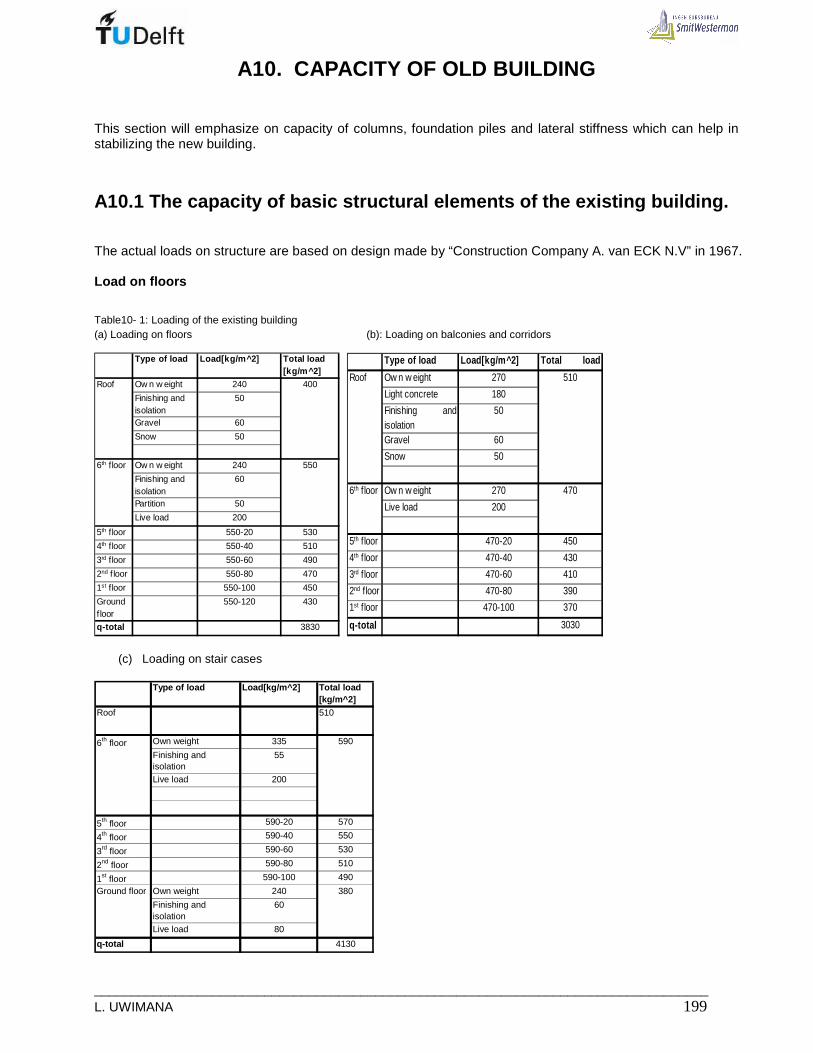
___________________________________________________________________________________ L. UWIMANA 199
A10. CAPACITY OF OLD BUILDING
This section will emphasize on capacity of columns, foundation piles and lateral stiffness which can help in stabilizing the new building.
A10.1 The capacity of basic structural elements of the existing building.
The actual loads on structure are based on design made by “Construction Company A. van ECK N.V” in 1967. Load on floors
Table10- 1: Loading of the existing building (a) Loading on floors (b): Loading on balconies and corridors
Type of load Load[kg/m^2] Total load [kg/m^2]
Ow n w eight 240
Finishing and isolation
50
Gravel 60
Snow 50
Ow n w eight 240
Finishing and isolation
60
Partition 50
Live load 200
5th floor 550-20 530
4th floor 550-40 510
3rd floor 550-60 490
2nd f loor 550-80 470
1st floor 550-100 450
Ground f loor
550-120 430
q-total 3830
Roof 400
6th floor 550
Type of load Load[kg/m^2] Total load[kg/m^2]Ow n w eight 270
Light concrete 180
Finishing andisolation
50
Gravel 60
Snow 50
Ow n w eight 270
Live load 200
5th f loor 470-20 450
4th f loor 470-40 430
3rd f loor 470-60 410
2nd f loor 470-80 390
1st f loor 470-100 370
q-total 3030
Roof 510
6th f loor 470
(c) Loading on stair cases
Type of load Load[kg/m^2] Total load [kg/m^2]
Own weight 335
Finishing and isolation
55
Live load 200
5th floor 590-20 570
4th floor 590-40 550
3rd floor 590-60 530
2nd floor 590-80 510
1st floor 590-100 490
Own weight 240
Finishing and isolation
60
Live load 80
q-total 4130
6th floor 590
Ground floor 380
Roof 510

_____________________________________________________________________________ 200 MSc Thesis
A10.1.1 Foundation
The foundation consists of foundation beam and piles. The beams are made of reinforced concrete whose reinforcement are designed based on load coming from the above structure. The load from the beams is transferred to the soil through the concrete piles-figure After finding out the loading for each component using the load from table2-1a, b, c; the total loads on piles were calculated. Those loads on piles are summarized in tableA10-2.and were used in designing the capacity of the existing foundation. All piles used have a square cross section 340x340 mm, 15m long and a square point 450x450 mm with a maximum load of 70 ton (700KN).
Figure A10- 1: Existing pile
Figure A10- 2: Existing pile in plan
TableA10- 2 : Total loading on piles
# Pile 1 2 3 4 5 6 7 8 9 10 11 12 13 14 15 16 17
Load[Kg] 66005 69170 68770 68600 61450 64120 48345 69625 64020 59880 60955 63080 69260 69260 69260 54600 58780
# Pile 18 19 20 21 22 23 24 25 26 27 28 29 30 31 32 33 34
Load[Kg] 53355 59880 59880 60955 63080 69260 69260 69260 54600 58780 53355 59880 59880 60955 63080 69260 69260
The maximum capacity of existing piles is 1736 KN as it was calculated in Appendix 11. Table A10-2 shows that a heavily loaded pile receives approximately 700 KN; there is therefore unused capacity which can bear moderate loads.

___________________________________________________________________________________ L. UWIMANA 201
A10.1.2 Columns
Figure A10- 3: Location of columns in old building
• Applied axial forces from gravity load
The gravity load forces in the columns come from the tributary areas. According to the calculation sheets from archives [20] , the loads used to design the columns of the existing structure are recorded in table A10-3. Axial forces in the columns and beams resulting from the horizontal loading should be estimated by simple static analysis of the analogous braced frame considering each infill as a diagonal strut. These two kind of axial forces are added to form the design force for each column.
Table A10-3 Load, moments and reinforcement of existing columns [20]
Nmax in Kg Mmax in Kgm
Nmax Mmax R-bar Nmax Mmax R-bar Nmax Mmax R-bar Nmax Mmax R-bar Nmax Mmax R-bar Nmax Mmax R-bar Nmax Mmax R-bar
Under 6th floor Col.C' 17060 1347 6ф10 19055 1048 6ф10 25580 1017 6ф10 25580 1017 6ф10 24030 1049 6ф10 25580 1017 6ф10 16510 1147 6ф10
Col. F 17060 1347 6ф10 19055 1048 6ф10 27295 1017 6ф10 25580 1017 6ф10 24030 1049 6ф10 25580 1017 6ф10 18220 1147 6ф10
Under 5th floor Col.C' 17060 1347 6ф10 19055 1048 6ф10 25580 1017 6ф10 25580 1017 6ф10 24030 1049 6ф10 25580 1017 6ф10 16510 1147 6ф10
Col. F 17060 1347 6ф10 19055 1048 6ф10 27295 1017 6ф10 25580 1017 6ф10 24030 1049 6ф10 25580 1017 6ф10 18220 1147 6ф10
Under 4th floor Col.C' 22600 1136 6ф10 25580 1017 6ф10 25580 1017 6ф10 25580 1017 6ф10 24030 1049 6ф10 25580 1017 6ф10 22150 1475 6ф12
Col. F 27215 1556 6ф12 30180 1449 6ф14 27295 1017 6ф10 25580 1017 6ф10 24030 1049 6ф10 25580 1017 6ф10 24435 1475 6ф12
Under 3rd floor Col.C' 28320 1346 6ф12 32090 1307 6ф12 32090 1307 6ф12 32090 1307 6ф12 30440 1348 6ф12 32090 1307 6ф12 27810 1806 6ф14
Col. F 34460 1766 6ф16 38230 1629 6ф18 34375 1307 6ф12 32090 1307 6ф12 30440 1348 6ф12 32090 1307 6ф12 25525 1806 6ф14
Under 2nd floor Col.C' 34050 1555 6ф14 38645 1598 6ф16 38645 1598 6ф16 38645 1598 6ф16 36650 1647 6ф16 38645 1598 6ф16 33465 2135 6ф18
Col. F 41725 1975 6ф20 46320 1960 6ф20 41500 1598 6ф18 38645 1598 6ф16 36650 1647 6ф16 38645 1598 6ф16 36320 2135 6ф18
Load Under 1st floor Col.C' 39790 1765 6ф18 45170 1925 6ф20 45170 1925 6ф20 45170 1925 6ф20 42820 2033 6ф20 45170 1925 6ф20 39020 2465 6ф22
Col. F 48990 2185 6ф22 54370 2250 6ф24 48600 1925 6ф22 45170 1925 6ф20 42820 2033 6ф20 45170 1925 6ф20 42450 2465 6ф22
Total Col.C' 8496 7943 7881 7881 8175 7881 10175
Moment Col. F 10176 9384 7881 7881 8175 7881 10175
Total moment 18672 17327 15762 15762 16350 15762 20350
Floor Member
Vertical load in Kg, moment in Kgm and reinforcemen t per column
Wall 1 Wall 2 Wall 3 Wall 4 Wall 5 Wall 6 Wall 7

_____________________________________________________________________________ 202 MSc Thesis
• Applied force due to horizontal load
Figure A10- 4: Old building frame loaded horizontally
As the frame with in-fill masonry behaves as braced frame, the axial load in columns due to horizontal load can be calculated as follow:
12
Hc
MF
b= ± ; 21
.2H wM q H= ; , . 1.28,6 28,6 /w w repq q L KN m= ⇒ = ; as there are 7 frames, one
takes 28,6 / 7 4 /KN m=
2 21 1. 4.19,6 768
2 2H wM q H KNm= ⇒ = , therefore768
1541
102
cF KN= ± = ±
Where Fc : axial force as a result of horizontal load MH: Moment due to horizontal load b and L: the width and the length of building
H : height of building ,w repq : Representative wind pressure
wq : wind load
TableA10-4: Axial load due to lateral moment and moment from vertical load
Lateral axis Total moment Width Equivalentaxial load
[ KNm ] [ m ] [ KN ]
1 955 10 1912 941 10 1883 926 10 1854 926 10 1855 932 10 1866 926 10 1857 972 10 194
768768
[ KNm ]
187173158
768768768768
204 768
due to vertical loadTotal moment Moment due to
horizontal load
158164158
[ KNm ]
• Axial load capacity of columns In a reinforced concrete column, both longitudinal steel and concrete assist in carrying the load. The links (stirrups) prevent the longitudinal bars from buckling. According to Euro Code 2 [23], the ultimate load capacity of column is given by the following expression
cd c st ydN f A A fα= +
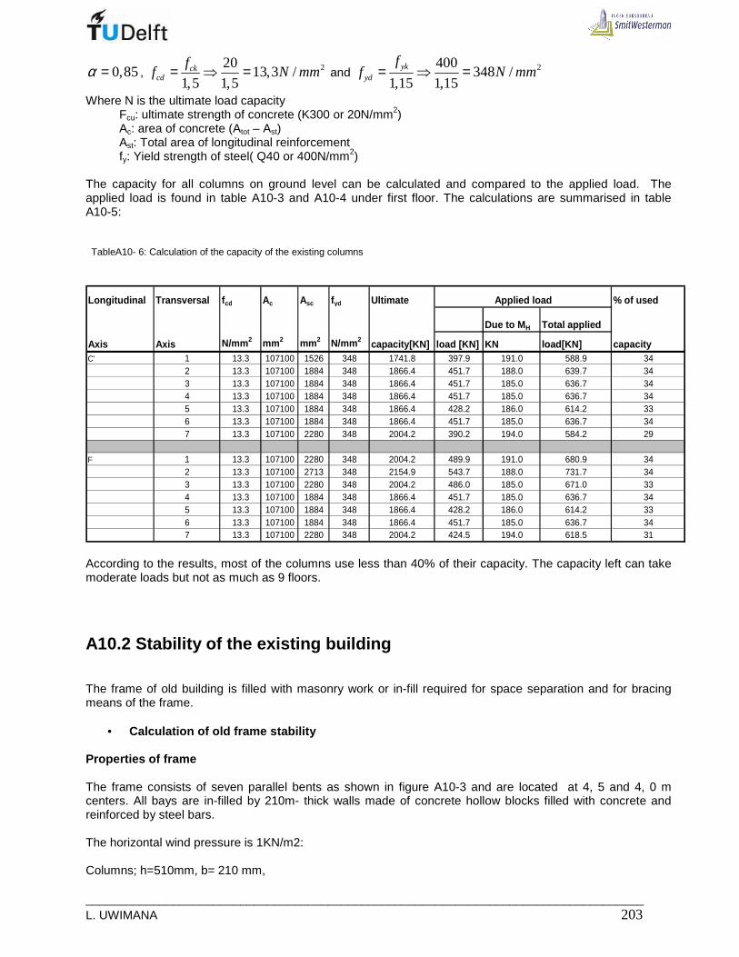
___________________________________________________________________________________ L. UWIMANA 203
0,85α = , 22013,3 /
1,5 1,5ck
cd
ff N mm= ⇒ = and 2400
348 /1,15 1,15
ykyd
ff N mm= ⇒ =
Where N is the ultimate load capacity Fcu: ultimate strength of concrete (K300 or 20N/mm2) Ac: area of concrete (Atot – Ast) Ast: Total area of longitudinal reinforcement fy: Yield strength of steel( Q40 or 400N/mm2) The capacity for all columns on ground level can be calculated and compared to the applied load. The applied load is found in table A10-3 and A10-4 under first floor. The calculations are summarised in table A10-5: TableA10- 6: Calculation of the capacity of the existing columns
Longitudinal Transversal f cd Ac Asc fyd Ultimate % of used
Due to M H Total applied
Axis Axis N/mm 2 mm 2 mm 2 N/mm 2 capacity[KN] load [KN] KN load[KN] capacityC' 1 13.3 107100 1526 348 1741.8 397.9 191.0 588.9 34
2 13.3 107100 1884 348 1866.4 451.7 188.0 639.7 343 13.3 107100 1884 348 1866.4 451.7 185.0 636.7 344 13.3 107100 1884 348 1866.4 451.7 185.0 636.7 345 13.3 107100 1884 348 1866.4 428.2 186.0 614.2 336 13.3 107100 1884 348 1866.4 451.7 185.0 636.7 347 13.3 107100 2280 348 2004.2 390.2 194.0 584.2 29
F 1 13.3 107100 2280 348 2004.2 489.9 191.0 680.9 342 13.3 107100 2713 348 2154.9 543.7 188.0 731.7 343 13.3 107100 2280 348 2004.2 486.0 185.0 671.0 334 13.3 107100 1884 348 1866.4 451.7 185.0 636.7 345 13.3 107100 1884 348 1866.4 428.2 186.0 614.2 336 13.3 107100 1884 348 1866.4 451.7 185.0 636.7 347 13.3 107100 2280 348 2004.2 424.5 194.0 618.5 31
Applied load
According to the results, most of the columns use less than 40% of their capacity. The capacity left can take moderate loads but not as much as 9 floors.
A10.2 Stability of the existing building
The frame of old building is filled with masonry work or in-fill required for space separation and for bracing means of the frame.
• Calculation of old frame stability Properties of frame The frame consists of seven parallel bents as shown in figure A10-3 and are located at 4, 5 and 4, 0 m centers. All bays are in-filled by 210m- thick walls made of concrete hollow blocks filled with concrete and reinforced by steel bars. The horizontal wind pressure is 1KN/m2: Columns; h=510mm, b= 210 mm,

_____________________________________________________________________________ 204 MSc Thesis
3 39 4. 210.510
2,32.1012 12
b hI I mm= ⇒ = =
Floor beams: h= 250 mm; b = 210 mm Façade beam: h= 250mm; b = 510 mm Concrete grade K300: Concrete grade K300 K225 Steel grade QR 24 QR 40
fck [N/mm2] 20 15 fsk [N/mm2] 240 400
fctm [N/mm2] 2,0 1,5 Es [kN/mm2] 210 210
Rd [N/mm2] 3,6 2,7
Properties of infill The infill consists of concrete blocks filled with concrete both of K 225.
The allowable compressive stress: 215 /mf N mm=
The allowable coefficient of friction: 0,2µ = The allowable bond shear strength [NEN-EN998-2:2003, NEN-EN206] is
20,15 /bsf N mm= The modulus of elasticity [NEN-EN1996-1-1] for short term is .E kE K f=
1000EK = ,.
Then 21000.15 15000 /E N mm= =
The infill diagonal:
1 0tan (2800 /10000) 15,6θ −= = cos 0,96θ = The diagonal length is
2 22800 10000 10385dL mm= + =
Wind shear at the base of one frame is as follow:
0 .wqQ h
n=
Where wq is the wind load acting on old building section to be raised to 15 floors
oQ: Shear force at the base of frame
h : height of building and n : number of lateral frames
⇒
25,5.19,6 71,4
7oQ KN= =
Structure shear strength – Infill shear failure:
( )1,43 0,8 / 0,2bs
s
f LtQ
h Lµ=
− −
( )( )0,15.10000.210
221022 2211,43 0,2 0,8 2800 /10000 0,2sQ N KN= = ⇒
− −
Structural shear strength – Infill Compressive failure:
2 342 cosc mQ f Ihtθ=
2 9 342.15.0,96 2,32.10 .2800.210 2435cQ KN= =
The infill is just adequate to carry the external shear on the basis of the shear failure criterion( strength =221KN compared with load of 71,4KN) and more than adequate on the basis of compressive failure criterion

___________________________________________________________________________________ L. UWIMANA 205
( strength = 2435KN). In addition to these calculations for the strength of the infill, the frame members should be checked to see that they are adequate to carry the bending moment and shear force due to lateral load. Checking the deflection A conservative estimate of the horizontal deflection of an in-filled frame is done by the calculating deflection of the equivalent pin jointed braced frame by replacing each infill by a diagonal strut(Figure A11-5) with a cross sectional area equal to the product of one-tenth of its diagonal length and its thickness [6]
Figure A10-5: Old building modelled as braced frame
(i). Flexural component The equivalent diagonal strut has this cross section:
21 1. 10385.210 218085
10 10d d dA L t A mm= ⇒ = =
An equivalent rectangular section of 650x336 mm can be used in a calculation which gives an equivalent area of 2218400dA mm=
As the infill with frame behave as braced bent, the deflection for each transverse frame is calculated as follows
3
2d g
Q d L
E L A Aδ
= +
[6] Calculation procedures : Compute the moment of inertia of the column sectional area about their common centroid.
2 2,1 7 ' '. .old F F C CI A L A L− = + 2 2 12 4
,1 7 510.210.1765 510.210.8150 7,45.10oldI mm− = + =

_____________________________________________________________________________ 206 MSc Thesis
313 4
,in f
210.100001,75.10
12y illI mm− = =
12 4, 17,5 7,45 25.10y totalI mm= + =
These values are put in table A10-5 column 7. Compute the value of the external moment at each story and enter the value in column 6. Determine for each story the value of hM/EI, and enter the results in column 9. Determine for each story i, the accumulation of . i fuθ from the ground level up to and including story i,
i fθ and record it in column10. Such accumulated values give the inclination of each story i due to flexure i fθ .
Record the product of ih and i fθ in column 11. i i fhθ is the drift in story i, i fu , due to flexure.
At each level, the value of the lateral drift is required, evaluate the accumulation of the story drift , i fu ,from
the ground level up and considered nth floor to give the drift totalu due to flexure. Enter these in column 12.
Therefore one can see that the total drift due to flexure on top of the building is 0,16 mm
TableA10- 5: Evaluation of flexural component of drift
Story Story Cum.height Cum.height Lateral External Fra me Mod. Elast. Storey Inclinastion Storey Cum.
heigh Ground -roof roof-ground load moment inertia E Inclination(Rads) θif drift Drift
mm mm mm KN/m Nmm x1012mm4 x104N/mm 2δθi=h*M/EI Rads mm mm
Roof 2800 19600 0 3,64 0 25 1,5 0,00 9,70E-06 0,03 0,166 2800 16800 2800 3,64 1,4E+07 25 1,5 0,00 9,70E-06 0,03 0,135 2800 14000 5600 3,64 5,7E+07 25 1,5 0,00 9,59E-06 0,03 0,104 2800 11200 8400 3,64 1,3E+08 25 1,5 0,00 9,16E-06 0,03 0,083 2800 8400 11200 3,64 2,3E+08 25 1,5 0,00 8,20E-06 0,02 0,052 2800 5600 14000 3,64 3,6E+08 25 1,5 0,00 6,50E-06 0,02 0,031 2800 2800 16800 3,64 5,1E+08 25 1,5 0,00 3,84E-06 0,01 0,01
Ground 0 2800 19600 3,64 7E+08 25 1,5 0,00 0,00E+00 0,00 0,00floor
The total drift on top of the building due to the flexural component is ; ; 0,16f total f i mmδ δ= ⇒∑
(ii).Shear component Compute the value of iQ for each story, and enter in column 4.
Compute the drift for each storey iδ , and enter it in column 11
Make the summation of each storey drift from the first floor up to the roof in column12. The final drift due to shear is 4,6 mm ( see table 10-6)
TableA10- 7 Evaluation of shear component of drift

___________________________________________________________________________________ L. UWIMANA 207
Story Lateral Acc.height Shear L BR LB Ad A B IB EBR storey drift(mm) Accu. load Ground -roof Q DriftKN/m mm KN mm mm mm2 mm2 mm4 N/mm2
mm
Roof 3,64 0 0 10385 10000 218400 52500 2,73E+08 15000 0,00 4,606 3,64 2,8 10,192 10385 10000 218400 52500 2,73E+08 15000 0,16 4,605 3,64 5,6 20,384 10385 10000 218400 52500 2,73E+08 15000 0,33 4,444 3,64 8,4 30,576 10385 10000 218400 52500 2,73E+08 15000 0,49 4,113 3,64 11,2 40,768 10385 10000 218400 52500 2,73E+08 15000 0,66 3,612 3,64 14 50,96 10385 10000 218400 52500 2,73E+08 15000 0,82 2,961 3,64 16,8 61,152 10385 10000 218400 52500 2,73E+08 15000 0,99 2,14
Ground 3,64 19,6 71,344 10385 10000 218400 52500 2,73E+08 15000 1,15 1,15floor
3
2id g
Q d L
E L A Aδ
= +
; ; 4,6s total s i mmδ δ= ⇒∑
The total drift is the summation of both flexural and shear drifts:
; ; 0,16 4,6 4,8total f total s total mmδ δ δ= + ⇒ + =

_____________________________________________________________________________ 208 MSc Thesis

___________________________________________________________________________________ L. UWIMANA 209
APPENDIX 11. FOUNDATION DESIGN
A11.1 Load on foundation
The load on foundation is basically made of three components: • Self weight of all structural members • Variable loads( Occupants and furniture) • Lateral load ( Wind and second order effect)
A11.1.1 Vertical load of foundation
Self weight Self weight comes from structural members themselves and depends on their properties. One considers the weight from floor slabs and floor finishing, services, columns, beams and concrete core. The part of the building which is put on top of the existing building has a load of 6,14 KN/m2 for roof and 7,14 KN/m2 for other floors (see Appendix2). Variable load The function of this building is accommodating people; the variable representative load of 1,75KN/m2 was selected according to NEN 6702. [1]
A11.1.2 Lateral loads
The lateral used in this design is the wind load and the load coming from imperfection. According to Appendix 2, the design lateral load to the structure is 54,4KN/m. The lateral load moment causes tension in windward side and compression in leeward side to the foundation-figure A11-1
FigureA11- 1: Vertical pressure on pile foundation due to lateral load The load on pile due to lateral moment is determined by using the following formula [24].
.
.later
M xP
I= With 2
.
1
2 laterM q h=
X: distance from the building center to the edge pile and h, the height of the building max
2
1
. .i
i iI n A x= ∑
iA is the area of pile
n: is the number of pile Xi is distance from the building center to the ith pile All loads stated above are combined as it is shown in appendix 10 and the critical combination will be used as design load on foundation.
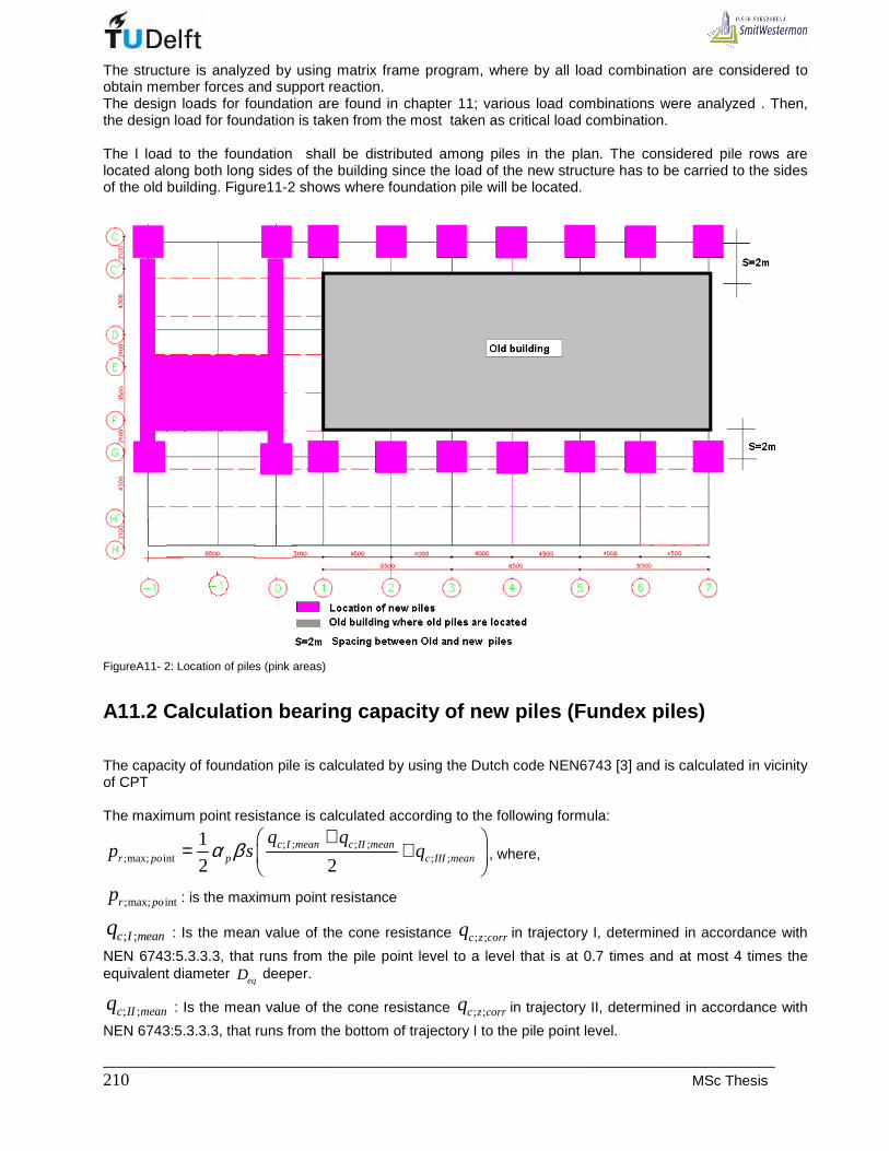
_____________________________________________________________________________ 210 MSc Thesis
The structure is analyzed by using matrix frame program, where by all load combination are considered to obtain member forces and support reaction. The design loads for foundation are found in chapter 11; various load combinations were analyzed . Then, the design load for foundation is taken from the most taken as critical load combination. The l load to the foundation shall be distributed among piles in the plan. The considered pile rows are located along both long sides of the building since the load of the new structure has to be carried to the sides of the old building. Figure11-2 shows where foundation pile will be located.
FigureA11- 2: Location of piles (pink areas)
A11.2 Calculation bearing capacity of new piles (Fu ndex piles)
The capacity of foundation pile is calculated by using the Dutch code NEN6743 [3] and is calculated in vicinity of CPT The maximum point resistance is calculated according to the following formula:
; ; ; ;;max; int ; ;
1
2 2c I mean c II mean
r po p c III mean
q qp s qα β
+ = +
, where,
;max; intr pop : is the maximum point resistance
; ;c I meanq : Is the mean value of the cone resistance ; ;c z corrq in trajectory I, determined in accordance with
NEN 6743:5.3.3.3, that runs from the pile point level to a level that is at 0.7 times and at most 4 times the equivalent diameter
eqD deeper.
; ;c II meanq : Is the mean value of the cone resistance ; ;c z corrq in trajectory II, determined in accordance with
NEN 6743:5.3.3.3, that runs from the bottom of trajectory I to the pile point level.

___________________________________________________________________________________ L. UWIMANA 211
; ;c III meanq : Is the mean value of the cone resistance ; ;c z corrq in trajectory III, determined in accordance with
NEN 6743:5.3.3.3, that runs from the pile point level to a level that is 8 times the equivalent diameter
eqD higher.
pα : is the pile class factor, determined in accordance NEN 6743:5.3.3.1.1
β is the factor that takes into account the influence of shape of the pile base determined in accordance NEN 6743:5.3.3.1.2 s is the factor that takes into account the influence of shape of the cross- Section of the pile base determined in accordance NEN 6743:5.3.3.1.3. The figure 14-3, give the failure envelope of the foundation sole around the pile point and where the mean cone resistances are taken.
FigureA11- 3: Impact depth (i). Foundation data According to the boring profile, the pile tip will be put on sand layer with sufficient bearing capacity (figure 11-4). It will be put at 15 m deep and Fundex pile with 380mm diameter will be used due to their benefits toward the non disturbance of the existing building foundation.

_____________________________________________________________________________ 212 MSc Thesis
FigureA11- 4: Boring Profile
int 0,45eq poD D m= = for shaft diameter of 380mm
0,7 0,7.0,45 0,315eqD m= =
4 4.0,45 1,8eqD m= =
8 8.0,45 3,6eqD m= =
In determination of ; ;c I meanq and ; ;c II meanq , the smallest values are taken from 0,7 eqD to 4 eqD
The determination of the respective average values of ; ;c I meanq, ; ;c II meanq
, ; ;c III meanq for the bottom range of
I / II N.A.P -16,8 m( 4 eqD ) is explained in figure 11-5.
; ; 14,7c I meanq MPa=
; ; 14,7c II meanq MPa=
; ; 4,5c III meanq MPa≃

___________________________________________________________________________________ L. UWIMANA 213
FigureA11- 5: Determination of ;max; intr pop with a depth range up to N.A.P-16,8m
(ii). Factors The following factors depend on the geometry and the type of the pile [NEN6743: 5.4.2.2.2-4]
0,9pα = ; 1β = and 1s =
,max, int
1 14,7 14,7.0,9.1.1 4,5 8,64
2 2r pop MPa+ = + =
(iii). Calculation of F r; max; point
2
6,max, int ,max, int int
.0,45. 8,64.10 . 1373
4r po r po poF p A KNπ= = =
(iv). Calculation of the maximum shaft resistance.
The pile capacity may increase due to some positive friction layers in the soil profile.
;max; ;max;. .r shaft r shaftF Op L p= ∆
Fr, max, shaft, is the maximum frictional force at sounding i, in KN pr, max,shaf , is the maximum shaft resistance in kN/m2; Os; ∆L, is the average circumference of the portion of the pile shaft in the layer, where pile foot is placed in m; ∆L is the length of the part of the pile, evolved in the shaft friction in m ∆L is determined by using CPT, figure 11-4 shows that the sand layer from the pile foot NAP-15m up to NAP - 14,2m may be counted. The sand layers above the clay layer (between NAP-14,2 and NAP-10) are not included because of this clay layer.
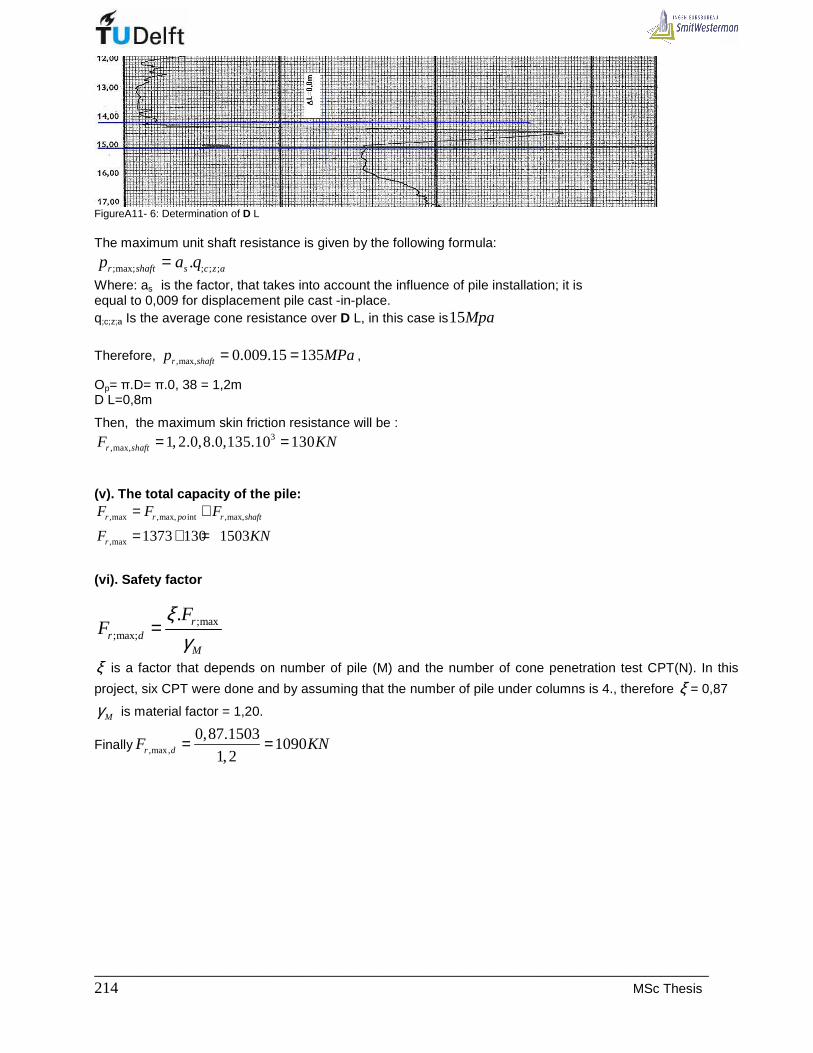
_____________________________________________________________________________ 214 MSc Thesis
FigureA11- 6: Determination of D L The maximum unit shaft resistance is given by the following formula:
;max; ; ; ;.r shaft s c z ap a q= Where: as is the factor, that takes into account the influence of pile installation; it is
equal to 0,009 for displacement pile cast -in-place. q;c;z;a Is the average cone resistance over D L, in this case is15Mpa Therefore, ,max, 0.009.15 135r shaftp MPa= = ,
Op= π.D= π.0, 38 = 1,2m D L=0,8m
Then, the maximum skin friction resistance will be : 3
,max, 1, 2.0,8.0,135.10 130r shaftF KN= =
(v). The total capacity of the pile:
,max ,max, int ,max,
,max 1373 130 1503r r po r shaft
r
F F F
F KN
= +
= + =
(vi). Safety factor
;max;max;
. rr d
M
FF
ξγ
=
ξ is a factor that depends on number of pile (M) and the number of cone penetration test CPT(N). In this
project, six CPT were done and by assuming that the number of pile under columns is 4., therefore ξ = 0,87
Mγ is material factor = 1,20.
Finally ,max,
0,87.15031090
1,2r dF KN= =
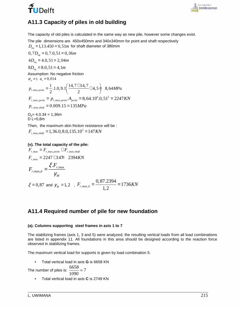
___________________________________________________________________________________ L. UWIMANA 215
A11.3 Capacity of piles in old building
The capacity of old piles is calculated in the same way as new pile, however some changes exist.
The pile dimensions are 450x450mm and 340x340mm for point and shaft respectively 1,13.450 0,51eqD m= = for shaft diameter of 380mm
0,7 0,7.0,51 0,36eqD m= =
4 4.0,51 2,04eqD m= =
8 8.0,51 4,1eqD m= =
Assumption: No negative friction 1pα =
0,014sa =
,max, int
1 14,7 14,7.1.0,9.1 4,5 8,64
2 2r pop MPa+ = + =
6 2,max, int ,max, int int. 8,64.10 .0,51 2247r po r po poF p A KN= = =
,max, 0.009.15 135r shaftp MPa= =
Op= 4.0.34 = 1,36m D L=0,8m
Then, the maximum skin friction resistance will be : 3
,max, 1,36.0,8.0,135.10 147r shaftF KN= =
(v). The total capacity of the pile:
,max ,max, int ,max,
,max 2247 147 2394
r r po r shaft
r
F F F
F KN
= +
= + =
;max;max;
. rr d
M
FF
ξγ
=
0,87ξ = and 1,2Mγ = , ,max,
0,87.23941736
1,2r dF KN= =
A11.4 Required number of pile for new foundation
(a). Columns supporting steel frames in axis 1 to 7 The stabilizing frames (axis 1, 3 and 5) were analyzed; the resulting vertical loads from all load combinations are listed in appendix 11. All foundations in this area should be designed according to the reaction force observed in stabilizing frames. The maximum vertical load for supports is given by load combination 5.
• Total vertical load in axis G is 6658 KN
The number of piles is: 6658
71090
≃
• Total vertical load in axis C is 2749 KN
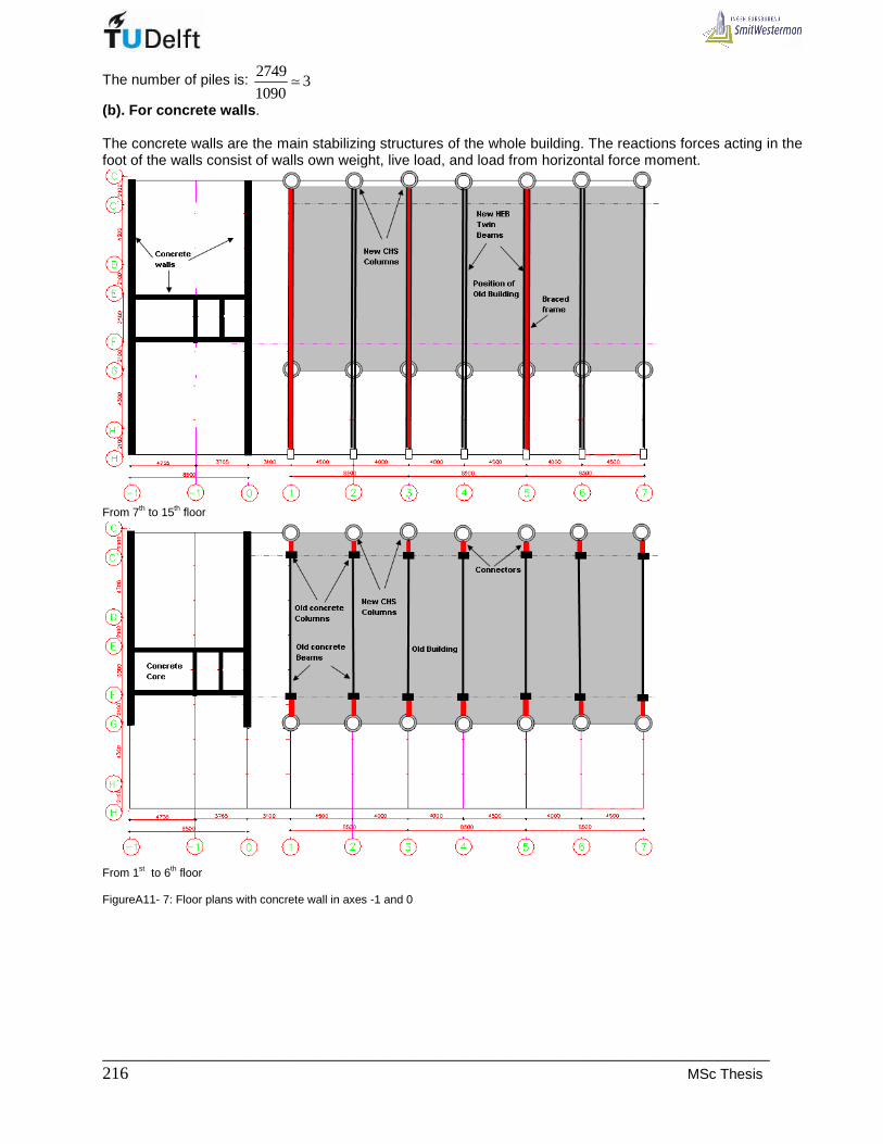
_____________________________________________________________________________ 216 MSc Thesis
The number of piles is: 2749
31090
≃
(b). For concrete walls . The concrete walls are the main stabilizing structures of the whole building. The reactions forces acting in the foot of the walls consist of walls own weight, live load, and load from horizontal force moment.
From 7th to 15th floor
From 1st to 6th floor FigureA11- 7: Floor plans with concrete wall in axes -1 and 0

___________________________________________________________________________________ L. UWIMANA 217
Section in axis -1 Section in axis 0 FigureA11- 8: section in axes -1 and 0 (i). wall -1:
• Self weight of wall and cantilever
Total wall area: 214,115.47,2 666m=
Openings: ( ) ( ) ( ) ( ){ } 21,62.1,225 1,82.2,185 2,02.1,225 1,795.1,875 .16 189m+ + + =
Net area: 2666 189 477m− =
Design load from wall self weight: ( ) ( )1,2 . . 1,2 477.0,250.24 3434net wall concreteA t KNγ ⇒ =
Cantilever: Total wall area: 25,785.26,64 154m=
Openings: ( ) ( ){ } 21,96.1,875 2,02.1,225 .9 55,3m+ =
Net area: 2154 55,3 99m− =
Design load from wall self weight: ( ) ( )1,2 . . 1,2 99.0,250.24 570net wall concreteA t KNγ ⇒ =
• Load from floors:

_____________________________________________________________________________ 218 MSc Thesis
[ ](1,2 1,5 )( )
(1,2.7,9 1,5.1,75) 16(4,25.14,115
floors DL VL floors
floors
F q q A
F
= +
= +
11619floorsF KN=
Cantileve r:
[ ]
(1,2 1,5 )( )
(1,2.7,9 1,5.1,75) 9(4,25.5,785 2976
floors DL VL floors
floors
F q q A
F KN
= +
= + =
Load from staircase:
(1,2 1,5 )( )
4,74(1,2.3,7 1,5.2) 16 .3,1
2
stair DL VL stair
floors
F q q A
F
= +
= +
7,44.118 878stairF KN= = , a half goes to the wall -1.
Total load is: 1 3434 570 11619 2976 439 19038wall self floors stairF F F F KN− = + + ⇒ + + + + =
Core contribution: ; 1
19038.3,5 4721
14,115coreF KN− = =
ii).Wall 0
• Self weight of wall 0 and its cantilever:
Total wall area: 214,115.47,2 666m= Openings:
( ) ( ) ( ) ( ) ( ){ }2
9 2,230.2,68 2 1,100.1,280 9 1,795.1,100 7 1,795.2,460 2,52(2,1 2 2,01
79,13 17,8 31 15,4 143,3m
+ + + + + +
+ + + =
Net area: 2666 143,3 523m− = Design load from wall self weight:
( ) ( )1,2 . . 1,2 523.0,250.24 3766net wall concreteA t KNγ ⇒ =
Total wall area of cantilever: 25,785.26,64 154m=
Openings: ( ) ( ){ } 22.1,28 1,1.2,46 .9 47,4m+ =
Net area: 2154 47,4 107m− =
Design load from cantilever wall self weight: ( ) ( )1,2 . . 1,2 107.0,250.24 616net wall concreteA t KNγ ⇒ =
• Load from floors :
[ ](1,2 1,5 )( )
(1,2.7,9 1,5.1,75) 16(5,8.14,115
floors DL VL floors
floors
F q q A
F
= +
= +
15856floorsF KN=
Cantilever floor:
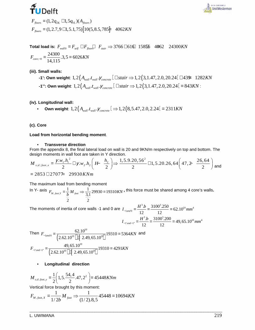
___________________________________________________________________________________ L. UWIMANA 219
[ ]
(1,2 1,5 )( )
(1,2.7,9 1,5.1,75) 10(5,8.5,785 4062
floors DL VL floors
floors
F q q A
F KN
= +
= + =
Total load is: 0 3766 616 15856 4062 24300wall self floors stairF F F F KN= + + ⇒ + + + =
; 0
24300.3,5 6026
14,115coreF KN− = =
(iii). Small walls:
-1’: Own weight : ( ) ( )1,2 . . 1,2 3,1.47,2.0,20.24 439 1282wall wall concreteA t stair KNγ + ⇒ + =
-1’’: Own weight : ( ) ( )1,2 . . 1,2 3,1.47,2.0,20.24 843wall wall concreteA t stair KNγ + ⇒ = :
(iv). Longitudinal wall:
• Own weight : ( ) ( )1,2 . . 1,2 8,5.47,2.0,2.24 2311wall wall concreteA t KNγ ⇒ =
(c). Core Load from horizontal bending moment .
• Transverse direction From the appendix 8, the final lateral load on wall is 20 and 9KN/m respectively on top and bottom. The design moments in wall foot are taken in Y direction.
2 21 1 2
; ; , 2 2
. . 1,5.9.20,56 26, 64. . 1,5.20.26, 64 47, 2
2 2 2 2
2853 27077 29930
s d foot x
w h hM w h H
KNm
γ γ = + − ⇒ + −
= + =
and
The maximum load from bending moment
In Y- axis , ,
1 129930 19310
3,12 2
M foot Y footF M KNb
= ⇒ = , this force must be shared among 4 core’s walls.
The moments of inertia of core walls -1 and 0 are 3 3
10 41 0
. 3100 .25062.10
12 12and
H bI mm− = = =
3 3
10 41' 1''
. 3100 .20049,65.10
12 12and
H bI mm− − = = =
Then ( ) ( )
10
1 0 10 10
62.1019310 5364
2.62.10 2.49,65.10andF KN− = =
+ and
( ) ( )10
1' 1'' 10 10
49,65.1019310 4291
2.62.10 2.49,65.10andF KN− − = =
+
• Longitudinal direction
2; ; ,
1 54,41,5. .47,2 45448
2 2s d foot yM KNm = =
Vertical force brought by this moment:
, ,
1 145448 10694
1/ 2 (1/ 2).8,5M foot X footF M KNb
= ⇒ =

_____________________________________________________________________________ 220 MSc Thesis
Once the loads of the structure and pile capacity are determined, then the number of piles can be estimates. In table A11-1, the loads associated to each structural member are presented as well as the required number of piles. In figure A11-9, one can see the layout of all piles. TableA11- 1: Required number of piles Structure Self
weight[KN]
Load from slab[KN]
Load from wind[KN]
Stair case [KN]
Total load[KN]
Pile capacity[KN]
Required number of piles
Wall 3434 11619 439 15492 15 Cantilever 570 2979 3549
1090 4
Wall -1
core 5364 5364 5 Wall 3766 15856 19622 18 Cantilever 616 4062 4678
1090 4
Wall 0
Core 5364 5364 1090 5 Small wall -1’ 843 4291 439 5573 1090 6
Small wall -1’’ 843 4291 5134 1090 5
Longitudinal wall E 2311 5347 7658 1090 8 Longitudinal wall F 2311 5347 7658 1090 8 Steel frame axis G 7x7
Steel frame axis C 3x7 Total number of piles 148
FigureA11- 9: Layout of foundation piles on ground plan For symmetry reason, axis 0 can have 28 piles instead of 27 pile and the total number of piles goes up to 149.