FLOATING STRUCTURES - TU Delft Repositories
163
ARCHITECTURAL ENGINEERING: DESIGN RESEARCH ARCHITECTURAL ENGINEERING GRADUATION STUDIO: GRADUATION PREPARATION Theo Mestemaker Jan Engels Suzanne Groenewold Wim Kamerling Florian Heinzelmann TU Delft (Delft University of Technology) LAB07 - Architectural Engineering 30 March 2012 Student Teachers University Studio Date P2 - Final report Research into the possibilities for a Floating Theatre in the Harbour of Scheveningen FLOATING STRUCTURES
-
Upload
khangminh22 -
Category
Documents
-
view
4 -
download
0
Transcript of FLOATING STRUCTURES - TU Delft Repositories

ARCHITECTURAL ENGINEERING: DESIGN RESEARCH
ARCHITECTURAL ENGINEERING GRADUATION STUDIO: GRADUATION PREPARATION
Theo Mestemaker
Jan EngelsSuzanne Groenewold
Wim KamerlingFlorian Heinzelmann
TU Delft (Delft University of Technology)LAB07 - Architectural Engineering
30 March 2012
Student
Teachers
UniversityStudio
Date
P2 - Final report
Research into the possibilities for a Floating Theatre in the Harbour of ScheveningenFLOATING STRUCTURES

(this page intentionally left blank)

(this page intentionally left blank)


DATA

(this page intentionally left blank)

NameStudent numberAddressPostal codePlace of residenceTelephone numberE-mail address
ThemeTeachers
Argumentation of choice of the studio
Title
T.W.J. Mestemaker (Theo)4025113Talmastraat 88385 [email protected]
Architectural Engineering LAB07 - TU Delft (Delft University of Technology)Ir. J.F. Engels (Jan) | ArchitectIr. S. Groenewold (Suzanne) | ArchitectIr. M.W. Kamerling (Wim) | Floating EngineerIr. F. Heinzelmann (Florian) | Revolt House
The architectural engineering studio is for me the best choice, because there is a strong rela-tion between architecture and engineering (technology). Coming from a technical background, this specialisation is the most related to me and I thought this was the most interesting and fun specialization to do.
Floating Structures:Research into the possibilities for a Floating Theatre in the Harbour of Scheveningen
PERSONAL INFORMATION
STUDIO
TITLE

PREFACE

(this page intentionally left blank)

This document contains the outline for the MSc3 architectural and engineering studies as part of the Architectural Engineering Studio aE7 (lab 07) and is made for the teachers to give feed-back on the progress of the graduation. The MSc3 project consists form two courses, with in the fi rst quarter; ‘Architectural Engineering: Design Research (AR3AE010)’ and in the second quater; ‘Architectural Engineering Graduation Studio: Graduation Preparation (AR3AE015)’. Passing this project (these two courses) will lead to the MSc4; Architectural Engineering Graduation Studio (AR4AE010)’, here will be the focus on the real design and engineering of the project.
The assignment for this project is to design and engineer a building, with the starting point of a technical fascination, in the Scheveningen Harbour of the city The Hague in The Netherlands. This location has fascinating possibilities and challenges that lie in the fi eld of interest of ar-chitectural engineering (building technology, climate, sustainability, product development), this creates opportunities to realise inspiring architecture.
The graduation project has to combine Architecture and Engineering and create a strong bal-ance and integration between these two aspects.


CONTENTS

(this page intentionally left blank)
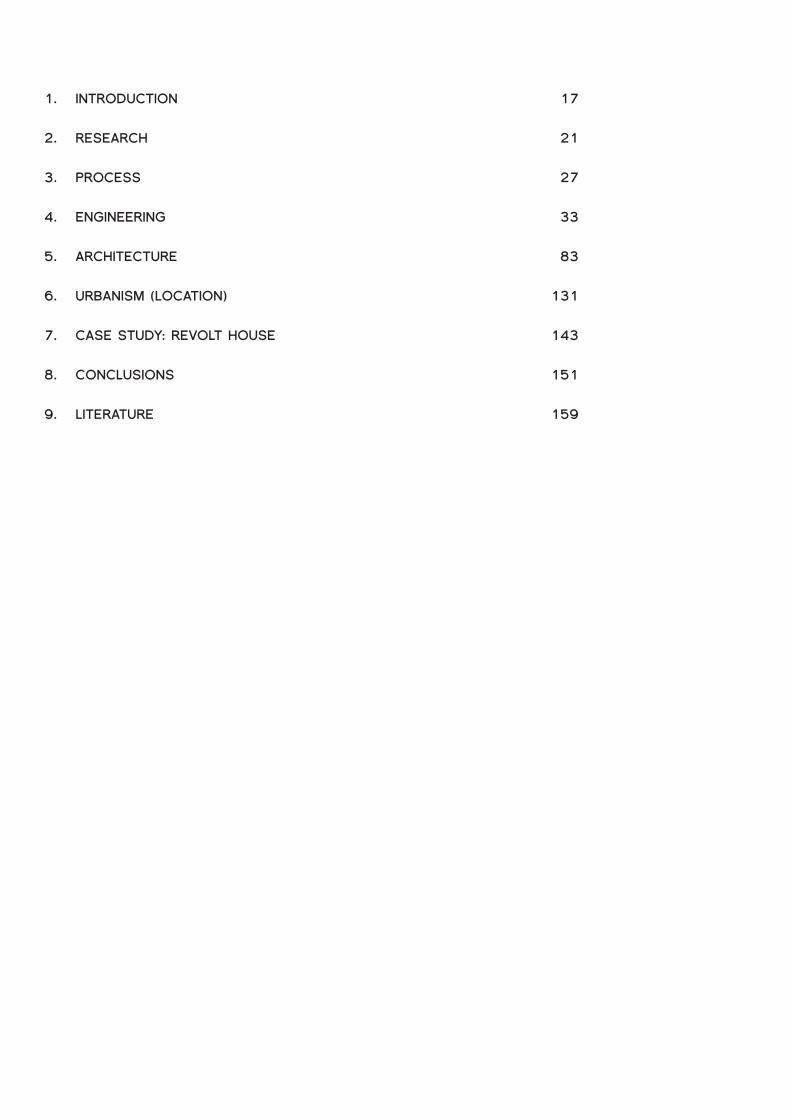
INTRODUCTION
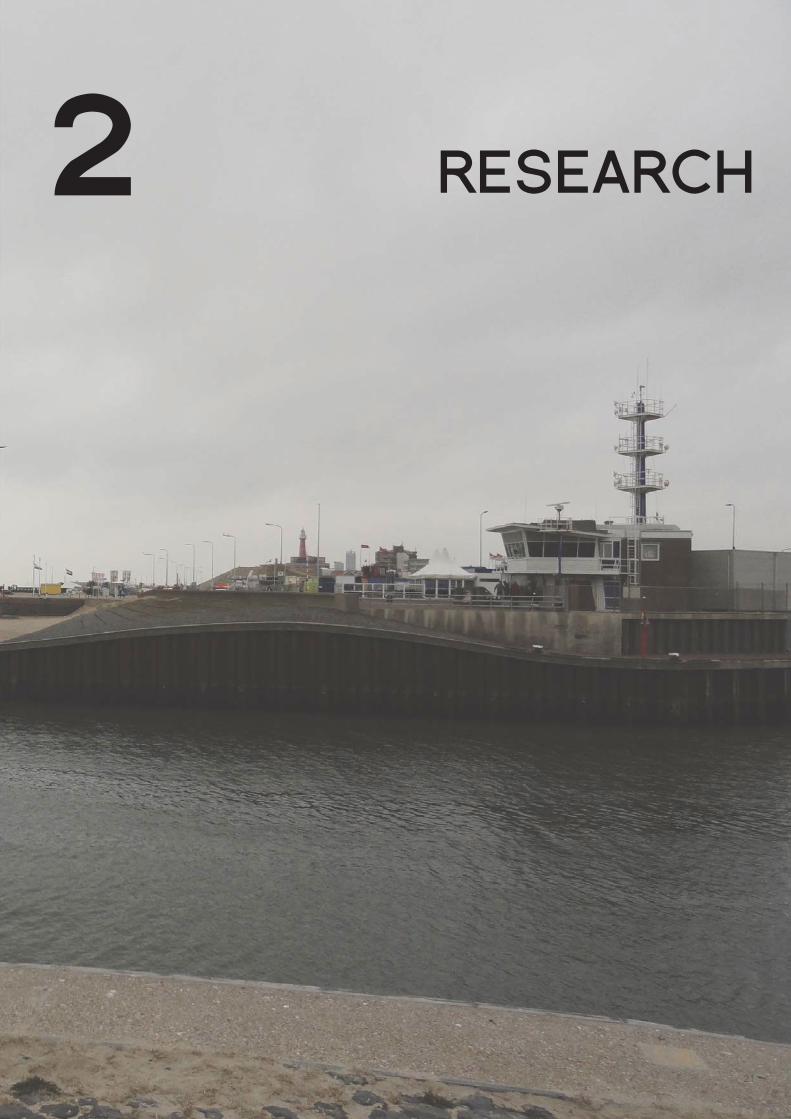
RESEARCH
PROCESS
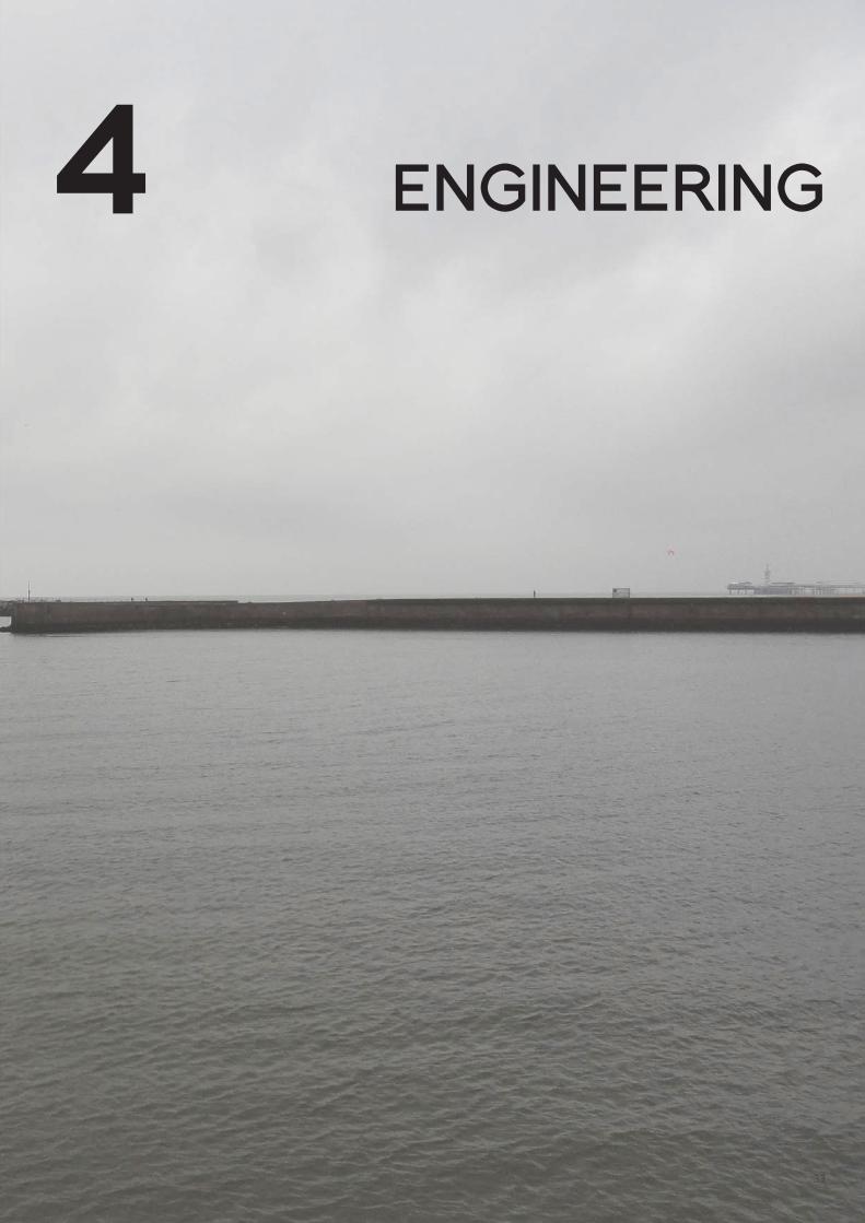
ENGINEERING
ARCHITECTURE
URBANISM (LOCATION)
CASE STUDY: REVOLT HOUSE
CONCLUSIONS
LITERATURE
1.
2.
3.
4.
5.
6.
7.
8.
9.
17
21
27
33
83
131
143
151
159

16

17
1 INTRODUCTION


19
FASCINATIONThe fi rst thing that came to mind, when I started with this project, was ‘water’. Every where you look in Scheveningen is water or is a function that has something to do with water. So I thought; why not fl oating on water? So my fascination for the graduation project is fl oating structures.
Also an other reason to choose for this fascination is that the world is in a climate change and one of the dangers of this climate change is fl ooding. Because Scheveningen/The Hague is located next to the sea it is in the danger area and in high risk of fl ooding. A fl oating structure can withstand this danger.
Architectural functionAfter the fi rst survey (P1 fi rst quarter) I have been asking myself what kind of function could be interesting when fl oating and could provide a challenge for architecture. The function that I have chosen is a ‘theatre’. Theatres are very interesting, because the building is not a building that is ‘standing still’, because of the dynamics and fl exibility of the stages and the performanc-es. There is also a atmosphere in theatres like a certain drama, even before the show starts.
The main advantage of a fl oating building or in my case a fl oating theatre is that the building is fl oating, which creates the dynamic aspects like movement and rotation. This gives a large fl ex-ibility which one of the most important features of a theatre. An advantage of fl oating or moving in water is that it is without much energy. During the show the stages can fl oat in front of the tribune and sail away, or the other way around. Also there is the possibility of having incredible large fl oating structures, like a boat or a fl oating air plane, because nothing on earth is larger than the oceans.
ReVolt HouseAs a side study I am participating in the ReVolt House project, this is the entry from the TU Delft for the Solar Decathlon Europe 2012. With this project I am designing, advising and cal-culating the properties for the fl oating system. In this way I am already familiarising myself with the design and engineering aspects of fl oating. My work on the ReVolt House can have further infl uences on my design. There are a lot of aspects of sustainability integrated into the project, which might be interesting for my own graduation project. Also rotation towards or from the sun, which is a aspect of fl oating could be integrated into my design.

20202020200020202020020020202020202020002020022220200002022020202220202000220
212121212121212122222221212212222121211112
2 RESEARCH

(this page intentionally left blank)
22

23
PROBLEM STATEMENTSea level rise and land subsidenceThe rise of the sea level is a natural phenomenon. Several measurements in New York and Rotterdam show a sea level rise of between 170 and 220 millimetre. These measurements are made during the last 100 years. The sea level rise in New York and Rotterdam could be attributed to the regional subsidence of the earth’s crust, due to the subtraction of water and because it is still slowly readjusting to the melting of ice sheets since the end of the last ice age. For these two cities, the land subsidence is between the 3 to 4 mm per year. In Jakarta the land subsidence is probably the main factor for the sea level rise, because some part of the cities are sinking at rates of 38 mm per year, mainly due to groundwater extraction.
This is an important issue, because two third of the cities in the world is built near water, and 50 per cent of the people live there. And still we are still spending money and building material on buildings that are in danger of being destroyed by nature, due to fl ooding. It should be bet-ter to invest in a more adaptive system like fl oating structures, which are not dependable on the current water protection systems.[1]
Partly due to this problem, I have decided to research the possibilities of fl oating structures. Because the location is at the entry of the harbour, there is an effect of the waves on the build-ing. This water is more interesting to research then the calm water inland, like on lakes.
Problem statement and research questionsThe problem statement is:How is it possible to realise a fl oating theatre that has a great fl exibility and can withstand the waves?
[1] Aerts, J.; Major, D.C.; Bowman, M.J.; Dircke, P.; Aris Marfai, M., (2009), Connecting delta cities: coastal
cities, fl ood risk management and adaptation to climate change, VU University Press
Map of the world showing high risk areas Forecast 2100 Netherlands,

24
RESEARCH QUESTIONSRelated to the problem statement I formulated some research questions. These research ques-tions are a substantiation to the problem statement and therefore can provide a better answer to the problem statement.
Research questions that are related to this problem statement are: - How can a structure fl oat? - What is the difference between the behaviour of fl oating structures in still inland water and on sea? - Which different kind of theatres do exist and which is suitable for on the water? - How fl exible does the theatre and the stage needs to be? - What is the relation between the building and the harbour/mainland? - Which size does the theatre needs to be and how many stages? - Which facilities are necessary for a fl oating theatre? - Which part of the theatre is fl oating and which part is fi xed? Specifi c questions will be added during the design process, when they are within the problem statement.
DESIGN ASSIGNMENTThe general design assignment is: “Design a fl oating theatre”. This theatre needs a certain amount of fl exibility/mobility. To determine the parameters of the building and get a more speci-fi ed design assignment, I did several studies.
Different studies - Floating bodies; - Theatre typologies; - Timeline of tribunes; - Timeline of stages; - Technical data for theatres (angles/slope); - Aspects of fl otation; - Floating related to theatre functions; - Location related to the harbour (relation with harbour/land); - Location research.

25
RESEARCH TOPICSThe research topics are stated in the previous paragraphs. The main research topics are: Engineering, Architecture, Urbanism (Location) and the Case study: ReVolt House. The four research topics all have different kind of studies.
Because the research contains a large amount of data, most of the research is located in the appendixes and the ‘normal’ chapters give a summary of those appendixes and the results or the design input for the MSc4 project.
Summary of the different studies and research:
Engineering - Theory of fl oating (Hydrostatics/Archimedes); - Floating structures and technical background.
Architecture - Floating reference projects; - Theatre reference projects; - Typologies of theatres; - Typologies of fl oating theatres; - Architectural Data of theatres; - Building program; - Relation fi xed versus fl oating.
Urbanism (Location) - Routing/infrastructure of location; - Climate conditions; - Orientation (Sun); - Water Data (depths of the sea/wave information); - Relation between land and fl oating building; - Inspirational objects/materials of environment.
Case study: ReVolt House - Testing different fl oating shapes; - Calculating different fl oating structures; - Getting information about potential sustainable solutions; - Advising role in the ReVolt team about fl oating structures.

2626262626262626226262626226662

2727272722727272727277772727272727772277727277227272772277722722222222727227
3 PROCESS

(this page intentionally left blank)
28

29
METHOD DESCRIPTIONThe research is mainly divided into three levels 1. Theoretical level: This is the basis for the design and mainly consists of research that is aimed at generating knowledge (theory) about fl oating and theatres. 2. Empirical level: This level focuses on the evaluation of the gathered knowledge and thinking about what could be applied on the design. 3. Application Level: This level focuses on the application of the knowledge on the design. And this is the real design phase.
At the P2, the second survey (NL: tweede peiling), I should be at the stage of the empirical level. Until the P1, the fi rst survey, I did a technical research on the theory of fl oating and fl oat-ing structures. From the P1 until the P2, I am doing a more architectural related study.From the P2 until the P5 I will be designing and calculating my own building.
Tasks to do before P1 (fi rst survey) - Literature study on the theory of fl oating; hydrostatics; - Literature study on fl oating structures; buildings and civil engineering; - Explaining and calculation of fl oating structures; - Researching and calculating the possibilities for the fl oating body of the ReVolt House (Solar Decathlon Europe 2012).
Tasks to do before P2 (second survey) - Architectural study on different fl oating objects; - Architectural and technical study on theatres; - Explaining and calculation of fl oating structures; - Location research; - Design / Sketch ideas for my own building; - Researching and calculating the possibilities for the fl oating body of the ReVolt House (Solar Decathlon Europe 2012).
Tasks to do before P3 (third survey) - Continue with the architectural study on different fl oating objects; - Continue with the architectural and technical study on theatres; - Specify a location; - Design and evaluate my building; - Build models of designs.
Tasks to do before P4 (fourth survey) - Design and evaluate my building; - Build models of designs; - Floating calculations of the designed building; - Structural calculations; - Building Physics.
Tasks to do before P5 (fi fth survey) - Prepare fi nal presentation (models, drawings) - Design and evaluate my building; - Calculate the designed building;

30
LITERATURE AND REFERENCEAll the literature that is necessary for the research that I am going to use needs to be relevant to my research subject. It is hard to say which literature I am going to use this depends on the insights that I am getting during the design process.
Literature / information that is used (or going to be used): - Literature about the theory of fl oating; - Architectural books about theatres and public buildings; - Architectural data for technical input for the design of theatres, like the Neufert book; - Plans for the location, made by third parties, like the government. - Data of the KNMI (dutch weather institute), about the wave heights; - Sea maps, information about the depths of the sea; - Data of NASA, about the sea level rise. - Theatre precedents, with different scales/sizes; - Floating precedents, like fl oating houses and public buildings.
TIME PLANNINGBecause I already fi nished all my other courses of the Master 1 and 2, so I have all the time for the courses of the master 3 and 4. I also spend a lot of time on the fl oating calculations of the Revolt House project. Mainly my time frame is according to the schedule of the TU Delft.
Survey Time schedule/deadline
P1 AR3AE010 Architectural Engineering: Design Research - Technical fascination; - Lectures; - Research essays.
Week 44/45 - 20114 November 2011
P2 AR3AE015 Architectural Engineering Graduation Studio: Graduation Preparation - Site; - Program; - Building; - Research essays; - Learning plan;
Phase: Preliminary design
Week 8/9/10 - 201226 January 2012
P3 AR4AE010 Architectural Engineering Graduation Studio - Architectural design - Construction - Details
Phase: Defi nitive design
Week 15/16 - 2012
P4 AR4AE010 Architectural Engineering Graduation Studio - Research essays; - Refl ections.
Phase: Final design
Week 19/20/21 - 2012
P5 AR4AE010 Architectural Engineering Graduation Studio - Final presentation.
Phase: Exam
Week 25/26/27 - 2012
(this page intentionally left blank)
31

32323232323232323232232332333
3333333333333333333333333333333
4 ENGINEERING

(this page intentionally left blank)
34

35
THEORY OF FLOATINGTo get an object or a building to fl oat, it is necessary to understand the theory of hydrostatics. Floating buildings are simply buildings that are founded on a liquid, mostly water.
Liquids can only be loaded with a pressure force; shear and tensile forces cannot be taken by the liquid. This can become diffi cult when the load isn’t evenly distributed.
To understand the basics of hydrostatics it is necessary to know the law of Archimedes of Syracuse.
ARCHIMEDESArchimedes of Syracuse, 250 before Christ, better known as Archimedes did a study on fl oat-ing bodies, in this study he did several propositions and then came up with the proof for those propositions. The propositions on fl oating bodies are based on the behaviour of a fl oating body in a liquid and to determine the size of it. These propositions are called the law of Archimedes.
Archimedes proposition 3, states that
Of solids those which, size for size, are of equal weight with a fl uid will, if let down into the fl uid, be immersed so that they do not project above the surface but do not sink lower.
Archimedes proposition 4, states that
A solid lighter than a fl uid will, if immersed in it, not be completely submerged, but part of it will project above the surface
Archimedes proposition 5, states that
Any solid lighter than a fl uid will, if placed in the fl uid, be so far immersed that the weight of the solid will be equal to the weight of the fl uid displaced.
Archimedes proposition 6, states that
If a solid lighter than a -fl uid be forcibly immersed in it, the solid will be driven upwards by a force equal to the difference between its weight and the weight of the fl uid displaced.
This means the action force is the same as the reaction force. This is also called the principle of buoyancy.
Archimedes proposition 7, states that A solid heavier than a fl uid will, if placed in it, descend to the bottom of the fl uid, and the solid will, when weighed in the fl uid, be lighter than its true weight by the weight of the fl uid displaced.
This means that a solid object which is heavier than a fl uid will sink.

36
HYDROSTATICSImmersionArchimedes proposition 6, states that: If a solid lighter than a fl uid be forcibly immersed in it, the solid will be driven upwards by a force equal to the difference between its weight and the weight of the fl uid displaced.
This means the action force is the same as the reaction force. This is also called the principle of buoyancy. The gravitational force on a fl oating object equals the weight of the moved liquid and the weight of the moved liquid equals the upward force applied to this object.
With this law the immersion of fl oating bodies can be calculated, for each shape there is a dif-ferent calculation. The shapes that are studied are rectangular, triangular and cylindrical.
Rectangular fl oating body
Fupw w
= ∇γ .
Fupw = vertical upward force (reaction) [kN] w = density of water [kN/m3]; for water inland 10 [kN/m3] for sea water 10,3 [kN/m3] = displaced fl uid[m3]
∇ = d w l. .
d = depth of immersion [m] w = width of fl oating body [m] l = length of fl oating object [m]
F Fupw z
=
Fupw = vertical upward force (reaction) [kN] Fz = vertical downward force (action) [kN]
F w d lz
= 10. . .
dF
wl
z=10. .
d = depth of immersion (m) Fz = vertical force (kN) w = width of fl oating body (m) l = length of fl oating object (m)
Triangular fl oating body
F l dupw w
= γ β. . . tan
2
Fupw = vertical upward force (reaction) [kN] w = density of water (kN/m3), for water inland 10 kN/m3
l = length of fl oating object (m) d = depth of immersion (m) = the half angle of the triangle top
∇ = l d. .
2
tanβ
= displaced fl uid[m3] l = length of fl oating object (m) d = depth of immersion (m) = the half angle of the triangle top
Equilibrium between forces
Rectangular symbol
Triangular symbol
37
F l dz
= 10
2
. . .tanβ
dF
l tan
z=10. . β
d = depth of immersion (m) Fz = vertical force (reaction) (kN) l = length of fl oating object (m) = half the angle of the triangle top
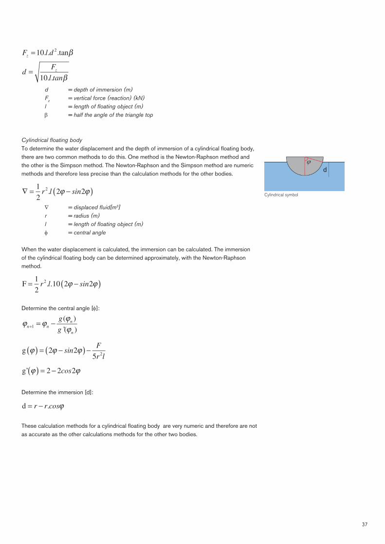
Cylindrical fl oating body To determine the water displacement and the depth of immersion of a cylindrical fl oating body, there are two common methods to do this. One method is the Newton-Raphson method and the other is the Simpson method. The Newton-Raphson and the Simpson method are numeric methods and therefore less precise than the calculation methods for the other bodies.
∇ = −( )1
2
2 2
2
r l sin. ϕ ϕ
= displaced fl uid[m3] r = radius (m) l = length of fl oating object (m) = central angle
When the water displacement is calculated, the immersion can be calculated. The immersion of the cylindrical fl oating body can be determined approximately, with the Newton-Raphson method.
F = −( )1
2
10 2 2
2
r l sin. . ϕ ϕ
Determine the central angle []:
ϕ ϕϕ
ϕn n
n
n
g
g+ = −
1
( )
’( )
g ϕ ϕ ϕ( ) = −( ) −2 2
5
2
sinF
r l
g’ ϕ ϕ( ) = −2 2 2cos
Determine the immersion [d]:
d = −r r cos. ϕ
These calculation methods for a cylindrical fl oating body are very numeric and therefore are not as accurate as the other calculations methods for the other two bodies.
Cylindrical symbol

38
Water pressureThe water is creating a force (pressure) on the fl oating body. The vertical component of the water pressure is equals to the gravitational force. The horizontal component of the water pressure equals itself.
p dw
= γ .
p = water pressure [kN/m3] w = density of water [kN/m3], for water inland 10 kN/m3.
Modules of subgrade reactionThe modulus of subgrade reaction describes the link between the deformation en the centric vertical load. This modulus is used for the calculation of foundations on a weak soil. First the modulus for a foundation of steel will be determined and then the foundation of a fl oating structure.
Foundation on steelThe modulus for a foundation on steel can be calculated by loading the foundation with a force F, which determines the tension on the underground and measure the settlement.
ku
=σ
k = modulus of subgrade reaction [kN/m3] = stress [kN/m3] u = settlement (m)
σ =F
l w.
This results in the formula:
kF
l w u=
. .
k = modulus of subgrade reaction [kN/m3] F = force (kN) l = length of fl oating object (m) w = width of fl oating body (m) u = settlement (m)
The modulus of subgrade reaction for a foundation on steel is varying between k = 10.000 and 50.000 kN/m3.
Floating foundationThe modulus of subgrade reaction for a fl oating body is similar to the modulus for a foun-dation on steel. The settlement [u] needs to be replaced by the immersion [d].
kF
l w d=
. .
k = modulus of subgrade reaction (kN/m3) F = force (kN) l = length of fl oating object (m) w = width of fl oating body (m) d = immersion (m)

39
Rectangular body The immersion for a rectangular body is:
dF
wl
z=10. .
Substituting this formula in the formula of the fl oating foundation.
kF
l w d=
. .
Results in:k = 10 kN/m3
This foundation is a lot weaker than the foundation on steel, about a thousand times.
Triangular body The immersion for a triangular body is:
dF
l tan
z=10. . β
Substituting this formula in the formula of the fl oating foundation.
kF
l w d=
. .
Results in:
kF
d l tan=
10
2 . β
If we look at the basic shape of a triangular, the triangular is mostly the half of a rectangular (or square). So approximately we could say that, the modulus of subgrade reaction would be half of the square one, so k = 5 kN/m3.
Cylindrical body For the immersion of a cylindrical fl oating body, the approach is numeric, therefore it is not pos-sible to give a analytic description for the modulus of subgrade reaction for this shape.
Centre of buoyancyA fl oating object creates a water displacement, the centre of gravity of the displaced volume of water is called the centre of buoyancy. The centre of buoyancy is important, because the result-ing upward force engages here. The position of this centre of buoyancy can be calculated for the different shapes, assuming a centred or evenly distributed load on the fl oating body.
Rectangular body The centre of buoyancy for a rectangular body is:
B drec
=1
2
Brec = centre of buoyancy measured from water surface [m]

40
Triangular body The centre of gravity for a triangular body is:
zs
A
y=
z = position centre of gravity [m] Sy = static moment in the x-y area [m3] A = area [m2]
A w htri
=1
2
.
Atri = area triangle [m2] w = width of fl oating body (m) h = height of fl oating body (m)
S w hy
=1
3
2
.
Sy = static moment in the x-y area [m3] w = width of fl oating body (m) h = height of fl oating body (m)
Substituting these formulas into the formula of the centre of gravity, results in:
z h=2
3
The centre of gravity of an equilateral triangular object is seen from the base, on one third of the height.
The centre of buoyancy for a triangular body is then:
B dtri
=1
3
Btri = centre of buoyancy measured from water surface [m]
Cylindrical body The centre of gravity for a half cylindrical body is:
zr
=4
3
.
.π
z = position centre of gravity [m] r = radius (m)
This is approximately 0,42 times the radius (0,42r).
The centre of buoyancy for a half cylindrical body is then:
Br
rcyl
= ≈4
3
0 42
π,
Bcyl = centre of buoyancy measured from water surface [m]
This formula only applies to a cylindrical body that is half fully under water. Otherwise the Simp-son method should be used to determine the centre of gravity and buoyancy.
Centre of buoyancy for the different fl oating bodies
41
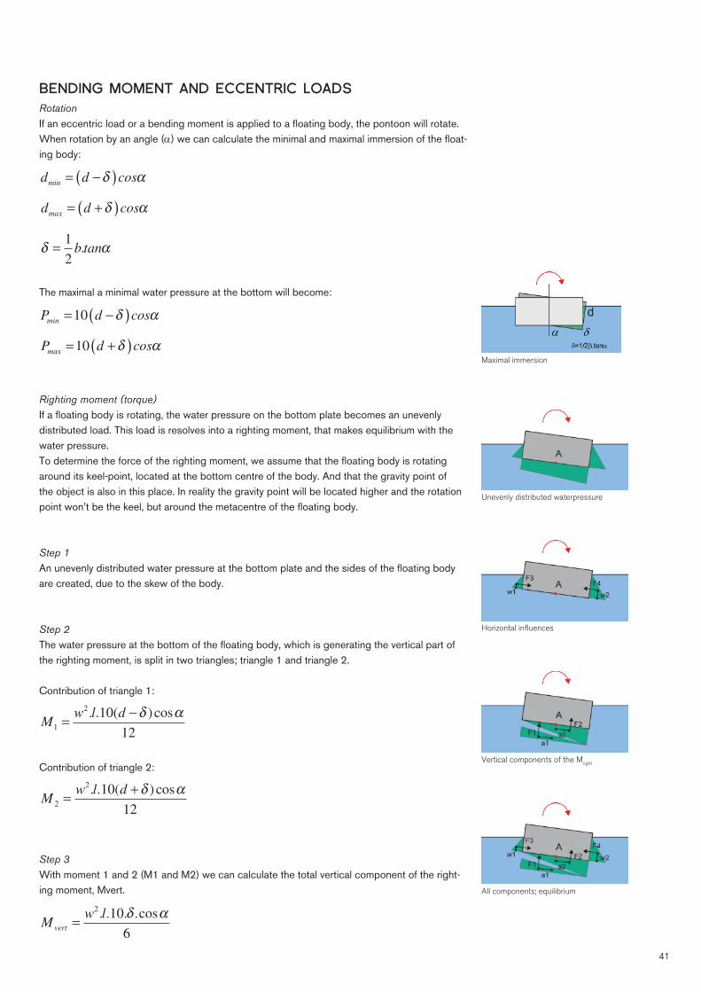
BENDING MOMENT AND ECCENTRIC LOADSRotationIf an eccentric load or a bending moment is applied to a fl oating body, the pontoon will rotate. When rotation by an angle () we can calculate the minimal and maximal immersion of the fl oat-ing body:
d d cosmin
= −( )δ α
d d cosmax
= +( )δ α
δ α=1
2
b tan.
The maximal a minimal water pressure at the bottom will become:
P d cosmin
= −( )10 δ α
P d cosmax
= +( )10 δ α
Righting moment (torque)If a fl oating body is rotating, the water pressure on the bottom plate becomes an unevenly distributed load. This load is resolves into a righting moment, that makes equilibrium with the water pressure.To determine the force of the righting moment, we assume that the fl oating body is rotating around its keel-point, located at the bottom centre of the body. And that the gravity point of the object is also in this place. In reality the gravity point will be located higher and the rotation point won’t be the keel, but around the metacentre of the fl oating body.
Step 1 An unevenly distributed water pressure at the bottom plate and the sides of the fl oating body are created, due to the skew of the body.
Step 2 The water pressure at the bottom of the fl oating body, which is generating the vertical part of the righting moment, is split in two triangles; triangle 1 and triangle 2.
Contribution of triangle 1:
Mw l d
1
2
10
12
=−. . ( ) cosδ α
Contribution of triangle 2:
Mw l d
2
2
10
12
=+. . ( ) cosδ α
Step 3 With moment 1 and 2 (M1 and M2) we can calculate the total vertical component of the right-ing moment, Mvert.
Mw l
vert=
2
10
6
. . . .cosδ α
Maximal immersion
Unevenly distributed waterpressure
Horizontal infl uences
All components; equilibrium
Vertical components of the Mright

42
Step 4 The water pressure at the sides of the fl oating body result in an extra moment, this we also split up into two triangles.
Contribution of triangle 3:
Ml d
3
3
10
6
= −−. ( ) cosδ α
Contribution of triangle 4:
Ml d
4
3
10
6
= −+. ( ) cosδ α
Step 5 With moment 3 and 4 (M3 and M4) we can calculate the total horizontal component of the righting moment, Mhor.
Ml d
hor=
+. ( . . ) cos10 6 2
6
2 3δ δ α
Step 6 With the horizontal (Mhor) and vertical (Mvert) moments calculated, it is now possible to calcu-late the total righting moment, Mright. The summations of the vertical and horizontal moments make equilibrium with the external moment (Mext), this results in: M M M M
ver hor right ext
+ = =
Mright
= +M M
ver hor
M Fw
dd
w
dright
= + +⎛
⎝⎜
⎞
⎠⎟sin .
.(tan )
αα2 2 2
12
1
2 24
When the centre of gravity of a fl oating body is higher compared to the keel point, a different formula should be used to calculate the righting moment.
Spring rateThe spring rate of a fl oating body describes the relation between the size of the righting mo-ment and the angle of rotation of the foundation.
CM
=α
C = spring rate (kNm/rad) M = Moment (kNm) = angle of rotation (rad)
If we substitute the formula if the righting moment into the formula of the spring rate we are able to determine the spring rate.
M C Fw
dd
w
d= = + +
⎛
⎝⎜
⎞
⎠⎟. sin .
.(tan )
α αα2 2 2
12
1
2 24

43
A fl oating body can only rotate a maximum of 5 degree in UGT, according to the building regu-lation, therefore the contribution of the angle () will be so small that it can be neglected. Also the term (tan)2 gives an outcome for the small angles of almost zero, so this is also negligi-ble. So we can remove the angle of rotation () from the formula, this results in a more simple formula:
C Fw
dd= +
⎛
⎝⎜
⎞
⎠⎟
2
12
1
2
SECOND ORDER EFFECTIn the previous paragraph we assumed that the load is applied at the keel of the fl oating body. However in practice this will not work. In reality the gravitational force will be applied at the centre of gravity of the total structure. The infl uence of the height of the centre of gravity will be researched in this paragraph.
THE SECOND ORDER EFFECT AT A CONVENTIONAL FOUNDATION
The position of the centre of gravity is determined by the mass of the object and the mass of the fl oating body. The higher the object (or building) the higher the centre of gravity is located.
If we assume that we have a fl oating building with the centre of gravity in the keel and we put a horizontal force (Fhor) against the building, then the total moment will be M = F
hor
.l , with l = the arm of the force or better the height of the building.
But if the centre of gravity is located at a higher point, the consequences will be greater in case of horizontal movement, because the gravitational force (Fz) will have a horizontal displacement and will generate an extra moment. This moment will increase if the height of the centre of grav-ity will increase, because the length of the arm will increase.
To understand this effect on a fl oating building; we fi rst take a look at an infi nitely stiff rod, with the length l, which is clamped into a resilient foundation, with a spring rate C. The rod is verti-cally loaded with a force Fz and horizontally with a force Fh.
Step 1 The foundation is loaded with a moment M = F
hor
.l . Because of this moment, the foundation is rotating over an angle .
α =M
C
Step 2Because of this rotation, a displacement (v) will occur at the top of the bar:
v l l= ≈.sin .α α
(this is for the small angles < 5 degree)
This displacement results in an extra moment:
δ M F v1
= .
A conventional foundation

44
Step 3 This extra moment increases the total moment, which is generating an increase in the angle of rotation with:
δδ
aM
C1
1=
Therefore the displacement will increase with:
δ δv l a1 1
= .
Step 4 This process will continue until the structure will collapse, so fall over, or until the increment ( . )δ v
n is infi nitely small.
δ . .M F v2 1
=
δ δ α. . .v l2 2
=
δ . .M F v3 2
=
δ δ α. . .v l3 3
=
The increment of the moment due to the displacement is called the second order effect. The determine if the structure will collapse as a consequence of the second order effect, the ratio between vn and δ .v
n is defi ned as n:
δ .vv
nn
=
There are three situations possible: n < 1, this means that the moment will increase with a lower amount every step; n = 1, this means that the moment will increase with the same amount every step; n > 1, this means that the moment will increase with the higher amount every step.
The critical point is n = 1, this means that the moment will increase with a constant rate and eventually the structure will collapse. Also n > 1, will result in a collapse of the structure. If n < 1, then the moment will increase to a certain value which can be approached. If the structure can coop with this moment force, the structure could be assumed as stable.
To approached this total moment, the summation of the displacement needs to be calculated.
∑ =−
vn
nv
1
Mn
nM
tot=
−1
0
The term n
n −1
is called the enlargement ratio and when n = 1, the structure will collapse,
so the critical length and critical force can be calculated:
lC
Fcrit
=

45
FC
lcrit
=
nC
F l
F
F
l
l
cri cri= = =.
THE SECOND ORDER EFFECT AT FLOATING STRUCTURES
The theory in the previous paragraph can also be applied to fl oating structures. The spring ratio of a fl oating object is much smaller compared to the ratio of a conventional founded structure. A fl oating foundation can be compared to an extremely weak foundation on soil.
This means that the second order effect will be determined by the rotation of the fl oating body. The contributions of the displacement of the building is compared to rotation of the fl oating body very small and van usually be neglected.
The distance l in the previous paragraph can be seen as the distance between the centre of gravity of the total building and the centre of rotation of the fl oating body.
lC
F
w
dd
cri= = +
⎛
⎝⎜
⎞
⎠⎟
2
12
1
2
This means that the critical length (lcri) depends on the depth or better immersion (d) and width (w) of the fl oating body. The width of the fl oating body is infl uencing the critical length quad-ratic, so increasing the width will have more effect than increasing the immersion of the body. When the critical length is calculated we can calculate the value of n and then subsequently calculate the value of Mtot.
STATIC STABILITY
About stability we can defi ed it into two different kinds of stability, the static and the dynamic stability. Static stability is related to the (long-term) horizontal or eccentric vertical loads. If a building is statically stable, it means that the building will not fall over (capsize) or fail under the infl uence of loads. Dynamic stability is about the motion generated by the motion of the water, where the building is fl oating in. When a building is dynamically stable it will say that it will not be resonated by the infl uence of the waves of the water.
STABILITY AND SKEW
A fl oating object or building is in balance when the summation of the horizontal, the vertical and the moment forces are equal to zero, so Fhor = 0, Fver = 0 and M = 0. This means that the building is in an equilibrium state.
There are three kinds of reactions and states of equilibrium possible: - The building will return to it equilibrium state (stable equilibrium); - The building will not return to its equilibrium state (labile equilibrium); - The building will return to an equilibrium state in a displaced state - (indifferent equilibrium).
A fl oating building needs to be in equilibrium. Stability for a fl oating building can be described as the return to its original equilibrium state. It needs to be able to absorb the disturbance in the balance (or equilibrium).
The change in height of the centre of gravity
46
So if a fl oating building will skew, not capsize (or fall over) and then return to its original state, then the building will be seen as stable. If it stays in its skewed position, then the building is also stable, but it has found a new equilibrium. This is a situation is not desired and therefore the building should be designed in a way that the permanent loads create an equilibrium, with a zero rotation, so the building is horizontal levelled and the building needs to be able get back to its original equilibrium if the variable loads create a disturbance.
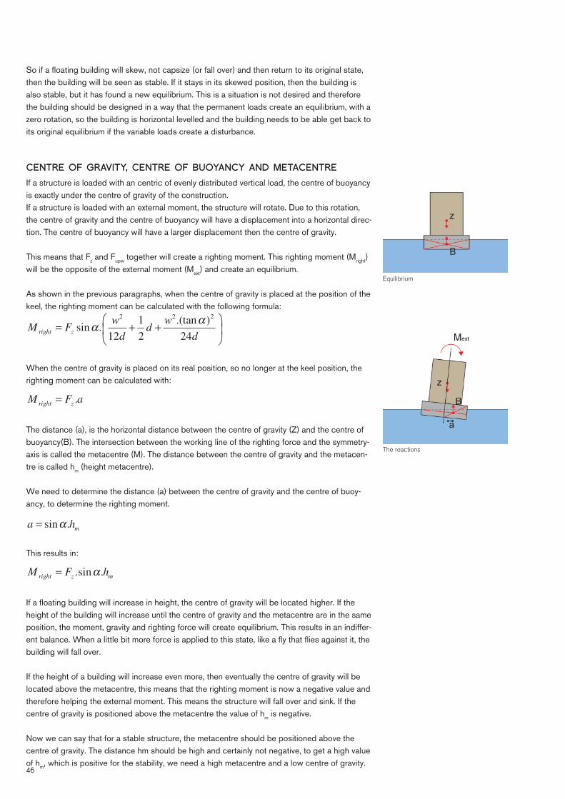
CENTRE OF GRAVITY, CENTRE OF BUOYANCY AND METACENTRE
If a structure is loaded with an centric of evenly distributed vertical load, the centre of buoyancy is exactly under the centre of gravity of the construction.If a structure is loaded with an external moment, the structure will rotate. Due to this rotation, the centre of gravity and the centre of buoyancy will have a displacement into a horizontal direc-tion. The centre of buoyancy will have a larger displacement then the centre of gravity.
This means that Fz and Fupw together will create a righting moment. This righting moment (Mright) will be the opposite of the external moment (Mext) and create an equilibrium.
As shown in the previous paragraphs, when the centre of gravity is placed at the position of the keel, the righting moment can be calculated with the following formula:
M Fw
dd
w
dright z
= + +⎛
⎝⎜
⎞
⎠⎟sin .
.(tan )
αα2 2 2
12
1
2 24
When the centre of gravity is placed on its real position, so no longer at the keel position, the righting moment can be calculated with:
M F aright z
= .
The distance (a), is the horizontal distance between the centre of gravity (Z) and the centre of buoyancy(B). The intersection between the working line of the righting force and the symmetry-axis is called the metacentre (M). The distance between the centre of gravity and the metacen-tre is called hm (height metacentre).
We need to determine the distance (a) between the centre of gravity and the centre of buoy-ancy, to determine the righting moment. a h
m= sin .α
This results in:
M F hright z m
= .sin .α
If a fl oating building will increase in height, the centre of gravity will be located higher. If the height of the building will increase until the centre of gravity and the metacentre are in the same position, the moment, gravity and righting force will create equilibrium. This results in an indiffer-ent balance. When a little bit more force is applied to this state, like a fl y that fl ies against it, the building will fall over.
If the height of a building will increase even more, then eventually the centre of gravity will be located above the metacentre, this means that the righting moment is now a negative value and therefore helping the external moment. This means the structure will fall over and sink. If the centre of gravity is positioned above the metacentre the value of hm is negative.
Now we can say that for a stable structure, the metacentre should be positioned above the centre of gravity. The distance hm should be high and certainly not negative, to get a high value of hm, which is positive for the stability, we need a high metacentre and a low centre of gravity.
Equilibrium
The reactions

47
THE HEIGHT OF THE METACENTRE
The metacentre is an important factor for the stability and can be described as the critical height of the centre of gravity. If the centre of gravity is above the metacentre the structure will become unstable and capsize.
The formula for the critical height of the centre of gravity is:
lw
dd
cri= +
2
12
1
2
The length is in this formula measured from the keel. Now we need to proof that the critical height of the centre of gravity is equal to the position of the metacentre.
The height of the metacentre to the centre of buoyancy can be calculated with the formula of Scribanti:
BMI
u=∇
+ ( )⎛
⎝⎜
⎞
⎠⎟1
1
2
2
tanα
BM = distance between centre of buoyancy (B) and = metacentre (M) Iu = second moment of area of the water plane section over = the long axis (m4) = displaced fl uid[m3]
Second moment of area:
I l wu
=1
12
3
.
(same as a regular beam) Substituting the previous formulas and the formula of the water displacement results in:
BMw
d= + ( )
⎛
⎝⎜
⎞
⎠⎟
2
2
12
1
1
2
tanα
Because the position of the metacentre depends on the rotation angle and the rotation angle of fl oating buildings can’t be larger than 5 degree, the last part of the formula can be neglected.
BMw
d=
2
12
If we want to know the height between the metacentre and the keel, we need to add the dis-tance between the centre of buoyancy and the keel. This distance is the half of the immersion, (0,5.d), the formula for the distance between the metacentre and the keel (KM) is:
KMw
dd= +
2
12
1
2
The distance between the keel and the centre of buoyancy, is half the immersion. When there is a rotation on the fl oating body, the centre of buoyancy moves vertically, therefore the distance will be slightly different. Because the maximum angle of rotation is 5 degree, this is so small that it can be neglected.

48
The formula for the distance between the metacentre and the keel (KM) and the formula for the critical height of the centre of gravity is equal:
lw
dd
cri= +
2
12
1
2 and KM
w
dd= +
2
12
1
2
The distance between the centre of gravity and the metacentre is called hm, so we call the distance between the keel (k) and the metacentre hk.
So the formula will be:
KM hw
dd
k= = +
2
12
1
2
hw
dd h
m rect z;
= + −2
12
1
2
hz = distance between centre of gravity and keel The above formulas are direction dependant. When the length and width of a fl oating body are different, the height of the metacentre will be different for the x and y-direction.
For the width direction: hw
dd h
m rect w z; ;
= + −2
12
1
2
For the length direction: hl
dd h
m rect l z; ;
= + −2
12
1
2
Different positions of the metacentre, creating a balanced, a indifferent balanced and a unbalanced situation
Position of the components (hk and hm)

49
THE HEIGHT OF THE METACENTRE FOR DIFFERENT SHAPES
We know how to calculate the position of the metacentre for a rectangular fl oating body, so now we can calculate the metacentre for other fl oating bodies:
Triangle
hd
d hm tri x z; ;
(tan )
= + −2
3
2
3
2β (x-direction)
hl
dd h
m tri y z; ;
= + −2
6
2
3
(y-direction)
Cylinder h
r
rr h
m cyl x z; ;
(sin )
( sin )
,=−
+ −4
3 2 2
0 58
3ϕ
ϕ ϕ (x-direction)
hl
rr h
m cyl y z; ;
sin .
( sin )
,=−
+ −ϕ
ϕ ϕ
2
3 2 2
0 58 (y-direction)
Multiply bodiesIf a fl oating body consist of multiple parts, linked together, so a combined body, we have to use the second moment of area of the fl oating body:
BMI
u=∇
∇ = w l dtot
. .
wtot = total width of the fl oating body
If we have two bodies, with each a width of w, then the total width wtot = 2.w1,2.
I I a A I a Au tot u body body u body body; ; ;
. .= + + +1 1
2
1 2 2
2
2
a1 = distance between the centre of gravity of the total body = and the centre of gravity of body 1 Abody1 = surface area of the water cross-section of body 1
In this case body 1 and body 2 are the same so:
I I a Au tot u body body; ;
( . )= +2 2
1 1
2
1
h KM h BM d hb a
dd h
m comb z z z;
= − = + − =+
+ −1
2
12
12
1
2
1
2
1
2
It depends on the direction of there are combined bodies, if there are combined bodies, the above formula should be used, otherwise the normal formula should be used.
Multiply bodies; example catamaran

50
DIFFERENT TYPES OF STATIC STABILITY
Stability is an important design aspect for fl oating building, the degree of stability becomes visible in the height of the metacentre. The height of the metacentre is infl uenced by: the width of the fl oating body, the immersion and the position of the centre of gravity. We can make a difference between shape-stability and weight-stability.
Shape-stabilityIf a fl oating body is rotating, the centre of buoyancy is displaced. The amount in which this is occurring, is depending on the width of the fl oating body. If the fl oating body gets wider, the centre of buoyancy will displace by a larger amount. This displaced is important for the shape-stability because the arm of the reaction force is increasing and thereby its moment. A building with a wide fl oating body has a large starting stability, but when the moment is increasing the rotation will increase as well and thereby the arm of the reaction force will increase less.
Weight-stabilityThe arm of the reaction force will increase when the fl oating body is wider, but also when the centre of gravity is lower. In case of a lower centre of gravity, the arm will increase at a slower rate but also increase less at a slower rate.
Weight-stability is not so important at the start of the, but the region covered by weight-stability is large. When the rotations get larger the structure is acting like a tumbler (tilting doll), be-cause the centre of gravity is low compared to the metacentre.
1 2 3
Weight-stability in a tumbler
The ultimate shape stability on land
(this page intentionally left blank)
51

52
HYDRODYNAMICSA fl oating structure is loaded ‘dynamically’ with a live load due to the effect of the waves. This is what is called hydrodynamics. The movement of the structure due to the infl uence of the waves needs to be minimal to let a fl oating structure be usable or practical for its function. The structure may not get to its own frequency otherwise it can capsize.In this chapter I focus on waves and the effect of the waves on a structure.
Airy (Linear) wave theoryWhen a water surface is exposed to wind, waves are created. A single wave that propagates itself along a line in the ‘x-direction’, which is the average water line. The water surface can be seen as a sinusoidal shape, see fi gure on the right. The defl ection to the average water line is called , and is a function of x and t (time).
The position of a particular point on the water surface can be described with the following formula:
ηπ π
x t HT
tL
x, sin( ) = +⎛
⎝⎜
⎞
⎠⎟
1
2
2 2
= defl ection of the water from the middle of the waterline [m] H = wave height, the height difference between peak and trough [m] x = distance wave in propagation direction [m] L = wavelength, the distance between two consecutive peaks or valleys [m] t = time [s] T = wave period, the time a water particle required to move a wavelength in the x-direction [s]
This formula can be rewritten as:
η ωx t a t k x, sin( ) = ⋅ + ⋅( )
With:
a H=1
2 and ω
π=
2
T and k
L=
2π
= amplitude [m] = angular frequency [s-1] = wavenumber [m-1]
Sinusoidal shape of a wave

53
Deep and shallow waterWith a sinusoidal wave the water particles have a circular movement, the orbital motion. The diameter of the orbital circle is dependable on the depth of the water. In deep water, there is suffi cient depth to the circular motion to reduce to zero. Water is regarded as deep water, when the water depth is greater than half of the wavelength. In shallow water, the shape of the orbital motion changes from a circle to an ellipse. Water is considered shallow water, when the water depth is less than 1/20th of the wavelength. The elliptical motion is not reduced to zero by the limited water depth. This creates horizontal velocities along the bottom of the sea, which cause shear stresses. These horizontal velocities change continuously magnitude and direc-tion. At a wave crest the direction is equal to the direction of the wave propagation. At a wave trough the direction is opposite to the wave propagation.
Orbital motion shallow and deep water
Wave speedThe propagation velocity of the wave can be determined with period T and wavelength L:
cL
T k= =
ω
The wave propagation speed, can also calculated using a other formula:
cgT d
L= ⋅
⎛
⎝⎜
⎞
⎠⎟
2
2
π
πtanh
c = propagation velocity [m/s] d = water depth [m]

54
Wave energyA wave has a certain amount of energy, a part of this is a part of kinetic energy, and a part is potential energy. The kinetic energy is created due to the orbital movement of the water parti-cles and the potential energy is created due to the defl ection of the water particles to the water surface.
For a wave (with length = L), the energy (E) that is generated per linear meter of crest can be determined with the following formula:
E E Ek p
E E g H Lk p
= = ⋅ ⋅ ⋅1
16
2ρ
Which results in the following formula:
E EL
g H18
2
Irregular wave fi eldsIn practice, the regular sinusoidal wave does not occur, only in a laboratory.
The wave fi eld of a water surface consists of a summation of single waves with different fre-quencies and amplitudes, directions and phases. Therefore, a irregular wave fi eld occurs, as is shown in the fi gure, from the defl ection of a water particle.
The behaviour of a irregular wave fi eld is less predictable then a sinusoidal wave. Interesting for a fl oating building is the wave height which can be expected at a certain surface. The wave height is not a constant factor. In order to determine the expected wave height, a exceedance probability is being used. The exceedance probability indicates the possibility that a particular value of the wave height will be exceeded.
A designation which is being used to determine the wave height with a certain exceedance probability, is the signifi cant wave height. This is the wave height with a exceedance probability of 13,5 %. This corresponds to the average wave height of one-third of the highest waves. The exceedance probability can be a higher value or a lower value, but the signifi cant wave height is the most usable and most general approach.
Irregular wave fi elds

55
The wave height (H) in a given wind fi eld, dependents on the following factors: - The string length (F) of the wind on the water (fetch) [m or km] - The water depth (d) [m] - The wind speed (U) [m/s] - The duration of the wind (t) [s]In order to determine the behaviour of the wave fi eld for a certain surface of the water, two different methods can be used, the Nomograms of Groen and Dorrestein and the method of Bretschneider.
There are three different kind of classifi cations for waves, in shallow water, in the transition zone from shallow to deep water, and in deep water.
Classifi cation d/L wavelength [m] Propagation speed [m/s]
deep water 1/2L
gT=
2
2πc
gL=
2π
transition zone 1/20 - 1/2
LgT d
L=
⎛
⎝⎜
⎞
⎠⎟
2
2
2
π
πtanh c
gL d
L=
⎛
⎝⎜
⎞
⎠⎟
2
2
π
πtanh
shallow water 1/20L T gd= c gd=
With: H = wave height [m] T = wave period [s] L = wavelength [m] d = depth [m] g = gravitational acceleration [m/s2]
Nomograms Groen and DorresteinThe Dutch weather institute (KNMI) developed nomograms to determine the wave height. The nomogram for shallow water is shown in the left fi gure below and for deep water in the right fi gure below. With these nomograms the wave height can be approximated.
Nomogram for shallow water Nomogram for deep water

56
Method of BretschneiderThis method is a different approach to determine the wave height. In this method the height is calculated depending on the string wave length, the depth of water and the wind speed. With these parameters, the signifi cant wave height (Hs) and the wave period (Tp) can be calculated.
H dF
d= ⋅ ⋅( ) ⋅
⋅
⋅( )
⎛
0 283 0 53
0 0125
0 53
0 75
0 42
0 75
, tanh , tanh
,
tanh ,
,
,
,
⎝⎝
⎜⎜⎜
⎞
⎠
⎟⎟⎟
T dF
d= ⋅ ⋅( ) ⋅
⋅
⋅(7 54 0 833
0 077
0 833
0 375
0 25
0 375
, tanh , tanh
,
tanh ,
,
,
, ))
⎛
⎝
⎜⎜⎜
⎞
⎠
⎟⎟⎟
With:
Hg H
U
s=⋅
2
T
g T
U
s=⋅
F
g F
U=
⋅2
d
g d
U=
⋅2
Because the method of Bretschneider is not limited to the nomograms, this method is easier in its use and more accurate.
Dynamic stability of fl oating structuresA building is dynamically unstable if the building gets in its own frequency due to the motion of the waves. The natural frequency is the point frequency that gets a structure in resonance.
This means that the building will move faster and harder then the waves and will capsize easily. This needs to be prevented.
A fl oating building has six degrees of freedom, translations and rotations in three directions to three axes. In the shipping world these movements are named as follows: - translation in the x-direction: surge - translation in the y-direction: sway - translation in the z-direction: heave - rotation around x-axis: roll - rotation around y-axis: pitch - rotation around z-axis: yaw
Depending on the amount of degree of freedom, a fl oating structure has more or less fl exibil-ity (in movement). For example if a structure is fi xed to a pole (moored), the translation in the horizontal plane (x and y-directions) is brought to a minimum and also rotation is less, but the translation in the vertical plane (z-direction) is still possible.
Square pontoonIf a square pontoon, with a perpendicular fl ow of waves (in the y-direction) is considered, the own frequencies of the heave and roll movements are important. This situation is also the most related to my project.

57
Natural frequency: roll-motionTo determine the own frequency of a structure for the roll motion (rotation around the x-axis), the following formulas can be used:
wg
j
m
p
02
=⋅h
0 = natural frequency [Hz] jp = polar mass radius of gyration [m] g = gravitational acceleration [m/s2]
With:
w T0 0
2⋅ = π
The the natural period of roll motion can be determined:
Tj
g h
p
m
0
2
=⋅ ⋅
⋅
π
T0 = natural period [s]
Note:This is a simplifi ed method, because the part of the water around the structure that is vibration, is also vibration with the structure. Due to this the mass of the total vibration part is larger, this is called the hydrodynamic mass. In the above formulas, this is neglected, because the impact is very small.
A building is in its resonance frequency as the natural period of the waves is equal to the natu-ral period of the building. For this reason, the natural period of the building needs to be larger than the natural period of the waves.
The previous formulas show that a large natural period is obtained by a large radius of gyration. Also a large metacentre height creates a small natural period, which is bad for dynamic stability. A large metacentre height is good for the static stability but bad for the dynamic stability.
The size of the polar radius of gyration can be calculated for each fl oating object. To get an indication of the size of the polar radius of gyration, some examples are shown: - Freight and passenger ships: j has a value between 0,35 . B and 0,45 . B; - Pontoons: j has a value between 0,45 . B and 0,55 . B; - Sailing: j has a value between 0,55 . B and 0,65 . B.
With: B = centre of buoyancy
The polar radius of gyration jp is the sum of the radii of gyration jy and jz. The polar moment of inertia is the sum of the moments of inertia Iy and Iz (also know as second moment of area).
jp = jy + jz
j
p
y zI
A
I
A= +
With:
Iy moments of inertia around the z-axis [m4] Iz moments of inertia around the y-axis [m4]

58
Natural frequency: heave-movementA building can not only swing about the y-axis, but also in the z-direction it can be ‘thrown up’, this is called the heave-movement. The natural frequency for the heave-movement can be deter-mined with the following formulas:
wg
d B0
1
8
=
+ ⋅ ⋅π
The natural period can be determined by:
Tg
d B
0
2
1
8
=⋅
+ ⋅ ⋅
π
π
A larger immersion and a low centre of buoyancy are increasing the natural period, what has a positive effect on the dynamic stability.
Waves close to shoreWhen a waves comes closer to shore, there will be some changes in the waves behaviour, due to the change in the depth of the water. In the shallow water, the propagation speed is decreasing. This difference in propagation speed along a wave crest leads to refraction. When the propagation speed and the wavelength are decreasing, the wave height will increases (shoaling). At some point, the wave will be so steep that it will break.
There are mainly four things that happen to a wave when approaching shore: - Refraction; - Diffraction; - Shoaling; - Branding zone created.
RefractionRefraction is the heave of the waves, when the waves are approaching the shore at an angle, the waves will start rotating towards the coast. The part of the wave that is still in shallow water, has less speed than the part that is in the deeper water. This difference leads to refraction. Because the energy between two waves is constant, this leads to a change of the wave height.
Refraction of waves

59
DiffractionAs a wave is approaching an obstacle, a part of the wave is being refl ected. The remained part of the wave will bend behind the obstacle. This process is called diffraction. The wave heights behind the obstacle are thereby reduced. Diffraction can occur above the water due to fl oating objects, and below the water, due to sandbanks.
ShoalingShoaling is the increase of the wave height due to the entrance of the wave into shallower water. If a wave enters shallow water, the speed, and wavelength are decreasing, but since the fl ow of the wave is constant, the wave height will increase. This is mainly due to the change in the orbital motion of the water particles.
Shoaling process
Diffraction of waves Diffraction of waves through a opening

60
Branding ZoneWhen a wave is shoaling, the steepness of the wave will increases, and eventually break. Due to this the wave energy is almost disappearing. The place where the waves are breaking is called the ‘branding zone’, or the ‘surf zone’. In order to determine the branding zone, a breaker index () is being used. The breaker index is the ratio between the wave height where the wave breaks and the water depth.
The breaker index can be calculated with the following formula; in this formula, the bottom is considered to be horizontal:
γ =H
h
b
At a individual wave, γ = 0 78, and gives:
H
h
b = 0 78,
With: Hb = wave height when wave breaks [-] h = water depth when wave breaks [-] = breaking index [-]
When the signifi cant wave height (Hs) is being used, instead of Hb, the ratio of = 0,5 - 0,6.Because in reality, the bottom of the coast is not horizontal, but at an angle. Therefore for waves that break under an angle there is a dimensionless parameter () Iribarren number ap-plied. The parameter is the ratio of the coastal slope and wave steepness.
ξα
=tan
/H L0 and
LgT
0
2
2
=π
With: = slope of the coast [°] H = wave height [m] L0 = wavelength in deep water [m] T = wave period [s]The way in which a wave breaks, depends on the steepness of the coast. There are four differ-ent types of breaking, they are depending on the Iribarren parameter.
Four different break types for different Iribarren parameters

61
Wave height and period on North Sea

(this page intentionally left blank)
62

63
FLOATING STRUCTURESSIMPLE STRUCTURESNorth poleGreenlandThe most simple fl oating structure is ice. Ice is the solid shape of water, and fl oats because the density of ice is lower than that of water. Ice can be found all around the world and therefore probably the most common fl oating struc-ture. In the northern regions in the world, close to the north pole there are a lot of icebergs fl oating in the ocean.
South AmericaBolivia - PeruThe Titicaca Lake is the largest lake of South-America, with an area of 8340 square km. The Titicaca Lake is situated in the Andes mountain range on the border of Peru and Bolivia. It is situated at 3.812 meter above sea-level and is the highest commercial navigable lake in the world. The depth of the lake is in most places between 140 and 180 meter and the deepest point is about 280 meters.
Macro, Meso, and Micro - The islands on three differ-
ent scale levels
The fl oating islands in Lake Titicaca
Iceberg near Greenland - North Pole

64
This lake is inhabited by the Uros-Indians. The islands are made from totora reeds stacked together. The islands are created many centuries ago and need a lot of maintenance. The reeds at the bottom of the island structures rot away quickly, so new reeds are added at the top con-stantly, about every three months. After thirty years the islands are replaced by new ones. The islands are anchored with ropes attached to sticks driven into the bottom of the lake.
About forty islands are inhabited, and almost everything on the islands is made from reed, like the houses and the boats. Because the islands are mostly placed in un-deep waters, the islands sometimes are on the ground and when the water level is high the islands are fl oating.
A disadvantage is that the rotting process is generating gasses, these are unhealty and are creating all kind of health issues for the people.
AsiaCambodiaNot only in South-America, but also in Asia, there are fl oating island structures. One of them is in the province Siem Reap of Cambodia. The people that live there, which are mostly fi shermen, have been living on water for centuries. The lake that they live on is the largest lake of South-Asia, and called the Tonlé Sap Lake.
This lake has an area of about 2.600 square kilometers in the dry period, but increases during the rain-period to about 24.600 square kilometers, which is almost ten times larger. There are different kind of villages in and around the lake, the ones in the lake is the Chong Khneas village, which is practically always fl oating, except when there are really dry periods. Mostly they change their location so that they always stay fl oating and there are close to the fi sh.
Unlike the Chong Khneas another community of three villages, called the Kampong Phluk, is not fl oating but placed on six meter high stilts, which lift the buildings above the water. During the dry period, the water in the lake is low. Then the villagers move out of their houses en build tem-porary houses on the ground. When the water level rises again, they demolish there temporary houses and move back into their original houses.
The fl oating city of Chong Khneas
The houses of Kampong Phluk
Living in a fl oating house (Chong Khneas)

65
Vietnam In South-east Asia a lot of fl oating villages can be found, not only in Cambodia, but also in Viet-nam, Thailand, Indonesia and China. Where the Cambodian fl oating dwellings look like normal houses, the Chinese fl oating villages exist mostly out of small boats or rafts.
The fl oating villages in Vietnam exist out of small houses build on top of rafts. The rafts exist out of wooden planks, which are connected to empty barrels and jerry cans as fl oaters. Like western people only would build for fun or in a survival situation.
MexicoSpiral IslandThe British artist Richart Sowa has built two fl oating artifi cial islands in Mexico, called the Spiral Island. The fi rst was destroyed by a hurricane in 2005; the second has been open for tours since 2008.
Spiral Island IThe fi rst island consisted from fi lled nets with empty discarded plastic bottles which supports a structure of plywood and bamboo. On this structure there was poured sand and planted numerous plants, including mangroves.The island had a two-story house, a solar oven, a self-composting toilet, and three beaches. In total around 250.000 bottles were used for the 20 by 16 meter structure. The mangroves keep the island cool, and became 5 m high.
Spiral Island IIThis island was initially 20 meters in diameter, which is nowadays expanded to 25 meters. Also this island is covered with plants and mangroves. This smaller island contains about 100.000 bottles. The island has three beaches, a house, two ponds, a solar-powered waterfall and river, a wave-powered washing machine and solar panels.
Village on water, Halong-Bay Vietnam
Spiral Island I
Spiral Island II Floating structure of Spiral Island II

66
THEORETICAL BACKGROUNDFor three of these fl oating bodies I have calculated the fl oating capacity. The dimensions are as accurate as possible.
ICEBERGAn iceberg is the most simple fl oating structure, and very easy to calculate. If I assume that there is 1 m3 of ice. The density of ice is 900 kg/m3, this means that this object has a mass of 900 kg = 9 kN.
Resulting upward force of ice:Rectangular fl oating body
Fupw w
= ∇γ .
Fupw = vertical upward force (reaction) [kN] w = density of water [kN/m3]; for water inland 10 [kN/m3] for sea water 10,3 [kN/m3] = displaced fl uid[m3]
∇ = d w l. .
d = depth of immersion [m] w = width of fl oating body [m] l = length of fl oating object [m]
We have a volume of 1 m3 of 1 by 1 by 1 meter, if we assume that the whole body will be im-merged under water, then the depth of immersion is 1 m. This results in a fl uid displacement of 1 m3 .
This means the total vertical upward force that can be generated is:10,3 . 1 = 10,3 kN.
The weigth of the ice is 9 kN; the remaining upward force will then be1,3 kN.
This means that the load that can be applied on the body is 1,3 kN/m2 this is 130 kg/m2. This is for a fl oating body of 1 meter high.
Floating schemes of the different structures For these different systems I made some schemes showing the principals of the structures.All these different systems have the same principal; a building or object, on a simple fl oating body, which are working according to the law of Archimedes.
Lake Titicaca
Different kind of materials, used when there is a lack of the regular resources
Spiral island
Iceberg about 8/9 is always under water
Iceberg, the most natural and simple fl oating object Halong-Bay Vietnam
Chong Khneas

67
REED STRUCTUREArea of red square = 17 x 18 mm = 0,000306 m2
Total amount of reed rods = 9 rods
Average dimensions of reed outer diameter = 6 mm inner diameter (hollow) = 5 mm hollow percentage of lenght = 90% (this means that 90% of the length is hollow)
Total reed rods per m2 = 9 / 0,000306 = 29411 rods per m2
The volume of 1 rod of 1 meter = r2 . . l = 32 . . 1000 = 28274 mm3
Volume of a rod = 0,000028274 m3
The total volume of reed (including cavity) per m3 = 0,000028274 . 29411 = 0,83 m3
The amount of air in the cavity = hollow volume per meter per rodVolume of cavity = r2 . . (l . 90%) = 2,52 . . (1000 . 90%) = 17671 mm3
Volume of cavity = 0,000017671 m3
The total volume of cavity per m3 = 0,000017671 . 29411 = 0,52 m3
Total amount of material = 0,83 m3 - 0,52 m3 = 0,31 m3.Density of reed = 500 kg/m3 = 5 kN/m3
Mass of reed in 1 m3 = 500 . 0,31 = 155 kg = 1,5 kN
Resulting upward force of reed:We have a volume of 0,83 m3 (the rest is cavity that can be fi lled with water, because we are not sure if the reed that is stacked together is air tide) of 1 by 1 by 1 meter, if we assume that the whole body will be immerged under water, then the depth of immersion is 1 m. This results in a fl uid displacement of 0,83 m3 .
This means the total vertical upward force that can be generated is:10 . 0,83 = 8,3 kN.
The weigth of the reed is 1,5 kN; the remaining upward force will then be6,8 kN.
This means that the load that can be applied on the body is 6,8 kN/m2 this is 680 kg/m2. This is for a fl oating body of 1 meter high.
BARREL STRUCTUREThe material is HDPE and it has a density of 950 kg/m3. The hollow barrel has a thickness of 2 mm (0,002 m).
This means that the outer volume of the cilinder is:r2 . . l = 0,52 . . 1 = 0,785398 m3
This means that the inner volume of the cilinder (the cavity) is:(r - t . 2)2 . . (l - t . 2) = (0,5 - 0,002 . 2)2 . . (1 - 0,002 . 2) = 0,769791 m3
with t = thickness
Optimized amount of reed
One barrel of 1 by 1 by 1 m; radius 0,5m
68
This means that volume of the material is:outer volume - inner volume = 0,785398 - 0,769791 = 0,015608 m3
The mass of the barrel (cilinder) is then:volume . density = 0,015608 . 950 = 14,83 kg = 0,15 kN
For the calculation we assume that we can only place 1 barrel per square meter.
Resulting upward force of a barrel:The water displacement is equal to the outer volume, so per kubic meter of this fl oating struc-ture we have a water displacement of 0,785 m3.
This means the total vertical upward force that can be generated is:10 . 0,785 = 7,85 kN.
The weigth of the barrel is 0,15 kN; the remaining upward force will then be7,7 kN.
This means that the load that can be applied on the body is 7,7 kN/m2 this is 770 kg/m2. This is for a fl oating body of 1 meter high.
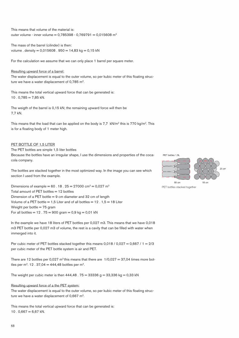
PET BOTTLE OF 1,5 LITERThe PET bottles are simple 1,5 liter bottlesBecause the bottles have an irregular shape, I use the dimensions and properties of the coca-cola company.
The bottles are stacked together in the most optimized way. In the image you can see which section I used from the example.
Dimensions of example = 60 . 18 . 25 = 27000 cm3 = 0,027 m3
Total amount of PET bottles = 12 bottlesDimension of a PET bottle = 9 cm diameter and 32 cm of lengthVolume of a PET bottle = 1,5 Liter and of all bottles = 12 . 1,5 = 18 LiterWeight per bottle = 75 gramFor all bottles = 12 . 75 = 900 gram = 0,9 kg = 0,01 kN
In the example we have 18 liters of PET bottles per 0,027 m3. This means that we have 0,018 m3 PET bottle per 0,027 m3 of volume, the rest is a cavity that can be fi lled with water when immerged into it.
Per cubic meter of PET bottles stacked together this means 0,018 / 0,027 = 0,667 / 1 = 2/3 per cubic meter of the PET bottle system is air and PET.
There are 12 bottles per 0,027 m3 this means that there are 1/0,027 = 37,04 times more bot-tles per m3. 12 . 37,04 = 444,48 bottles per m3.
The weight per cubic meter is then 444,48 . 75 = 33336 g = 33,336 kg = 0,33 kN
Resulting upward force of a the PET system:The water displacement is equal to the outer volume, so per kubic meter of this fl oating struc-ture we have a water displacement of 0,667 m3.
This means the total vertical upward force that can be generated is:10 . 0,667 = 6,67 kN.
PET bottles stacked together

69
The weigth of the PET bottles are 0,33 kN; the remaining upward force will then be 6,34 kN.
This means that the load that can be applied on the body is 6,34 kN/m2 this is 634 kg/m2. This is for a fl oating body of 1 meter high.
COMPARING THE RESULTSIceberg = 1,30 kN/m2 Reed structure = 6,80 kN/m2 Barrel structure = 7,70 kN/m2
PET system = 6,34 kN/m2
The iceberg has a very low value compared to the others, this is because the density is high and it is totally solid. An iceberg has a density equal to 90% of that of water, that means that 90% of the iceberg is always under water. So if you see an iceberg, then you have to imagine that the real iceberg is 9 times larger than what you see above the water.
The difference between the other structures is not really large. They are all around 7 kN/m3. For a building, the Barrel and PET structures are probably better, because the reed structure needs a lot of maintenance and can give health issues.
The difference between the barrel and the PET structure is that barrel structure can have about 1,4 kN/m2 more load on it. However, the PET system can also be replaced by a garbage system, because the PET bottles are caught in a net. There is a lot of garbage in the ocean which is fl oating, and by puting the nets into the ocean in the right place, they will be fi lled with garbage for free. And you also clean the ocean with this principal.
Therefore the PET system is probably the best choice for a building structure.

70
FLOATING BRIDGESOne of the fi rst fl oating structures was a bridge, the fi rst fl oating bridge have been built in ancient China by the Zhou Dynasty in the 11th century. During the centuries, fl oating bridges, mostly small, have been built all over the world.
Floating bridges were centuries ago oftenly built with small boats, were the real bridge was constructed on. The material that mostly was used is wood.
Most fl oating bridges were used by the armies as crossings. Those bridges where usually tem-porary, and are mostly destroyed after crossing or collapsed and carried a long.
Nowadays permanent fl oating bridges are still being built. Even highway bridges with a length of more than 2000 metres are constructed as fl oating bridges.
Floating Bridge - DubaiThe Floating Bridge is a pontoon bridge Dubai, which spans the entire Dubai Creek and is build in 2007. The bridge, which cost around 40 million euro, is a temporary bridge.The German company Waagner-Biro Stahlbau AG did the construction of the fi rst fl oating bridge in Dubai. The total length is 365 metres and the bridge has a width of 2 x 22 metres, the bridge has six lanes on two identical, mirrored decks. For each direction an independent sup-porting structure has been constructed. The parallel structures were designed to accommodate three lanes and one footwalk each.
Between the two fl oating pontoons made of concrete and steel, each 115 metres long and 22 metres wide, a hydraulically driven rotating middle section made of steel is positioned to allow for undisturbed navigation. To compensate for differences in level as well as for heeling and triming (skew) from traffi c loads and wave action acting on the ramp, another two rows of 28 transitory elements are installed between the fl oating pontoons and the transitory ramp on either bank.
Floating Bridge Dubai

71
The structure so formed dynamically distributed energy from waves and pressure from vehicles across the length and breadth of the platform in such a way that they canceled each other out. The elements are fi lled with highly resistant polystyrene plates, which serve as the actual fl oat-ing body supporting several thousands of tons of the heavy bridge on water level.
The bridge will probably be demolished between 2012 and 2014 and replaced with a perma-nent non-fl oating bridge.
Rosellini bridge - USAThe Governor Albert D. Rosellini Bridge (formerly the Evergreen Point Floating Bridge) is the longest fl oating bridge in the world. It spans 2.285 metres and carries a highway, State Route 520, across Lake Washington from Seattle to Medina, in the state Washington (West-Coast). The structure of the bridge consitst of column-supported high-rises near the ends of the bridge, and inbetween a real fl oating section.
Ferry Bridge - DelftThis a open-water ferry, which is powerd by a engine. The engine is a electric motor fed by a battery. The ferry is only for pedestrians and cyclists.
A ferry is a boat and in a certain way a bridge as well. It is a boat, because it fl oats and it can move freely over the water. But because it mostly stays in its track and is not moving freely it is behaving more as a bridge than a boat. Therefore in my opinion this ferry is a bridge instead of a boat.
Most of the older ferrys are made with concrete, steel and foam. Today they are made from fi breglass, which are lightweight.
The road of the Floating Bridge Dubai
Rosellini bridge USA
Ferry Bridge Delft
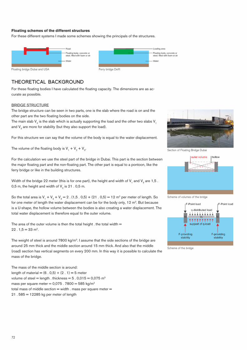
72
THEORETICAL BACKGROUNDFor these fl oating bodies I have calculated the fl oating capacity. The dimensions are as ac-curate as possible.
BRIDGE STRUCTUREThe bridge structure can be seen in two parts, one is the slab where the road is on and the other part are the two fl oating bodies on the side.The main slab V2 is the slab which is actually supporting the load and the other two slabs V1 and V3 are more for stability (but they also support the load).
For this structure we can say that the volume of the body is equal to the water displacement.
The volume of the fl oating body is V1 + V2 + V3.
For the calculation we use the steel part of the bridge in Dubai. This part is the section between the major fl oating part and the non-fl oating part. The other part is equal to a pontoon, like the ferry bridge or like in the building structures.
Width of the bridge 22 meter (this is for one part), the height and width of V1 and V3 are 1,5 . 0,5 m, the height and width of V2 is 21 . 0,5 m.
So the total area is V1 + V2 + V3 = 2 . (1,5 . 0,5) + (21 . 0,5) = 12 m2 per meter of length. So for one meter of length the water displacement can be for the body only, 12 m3. But because is a U-shape, the hollow volume between the bodies is also creating a water displacement. The total water displacement is therefore equal to the outer volume.
The area of the outer volume is then the total height . the total width = 22 . 1,5 = 33 m2.
The weight of steel is around 7800 kg/m3. I assume that the side sections of the bridge are around 25 mm thick and the middle section around 15 mm thick. And also that the middle (road) section has vertical segments on every 200 mm. In this way it is possible to calculate the mass of the bridge.
The mass of the middle section is around:length of material = (6 . 0,5) + (2 . 1) = 5 metervolume of steel = length . thickness = 5 . 0,015 = 0,075 m3
mass per square meter = 0,075 . 7800 = 585 kg/m2
total mass of middle section = width . mass per square meter = 21 . 585 = 12285 kg per meter of length
Floating schemes of the different structures For these different systems I made some schemes showing the principals of the structures.
Floating bridge Dubai and USA Ferry bridge Delft
Section of Floating Bridge Dubai
Scheme of the bridge
Scheme of volumes of the bridge

73
The mass of the side sections is around:area = outer area - inner area = (1,5 . 0,5) - ((1,5 - 2 . 0,025) . (0,5 - 2 . 0,025) = (1,5 . 0,5) - (1,45 . 0,45) = 0,75 - 0,6525 = 0,0975 m2.mass per meter length = area . density = 0,0975 . 7800 = 760,5 kg2 sections = 760,5 . 2 = 1521 kg.
So the weight of the bridge is around 12285 + 1521 = 13779 kg = 137,79 kN per meter of length.
Resulting upward force of bridge:The water displacement is equal to the outer volume, so per kubic meter of this fl oating struc-ture we have a water displacement of 33 m3.
This means the total vertical upward force that can be generated is:10 . 33 = 330 kN.
The weigth of the bridge is 137,79 kN; the remaining upward force will then be 192,21 kN.
This means that the load that can be applied on the body is 192,21 / 22 = 8,74 kN/m2 this is 874 kg/m2. This is for a fl oating body of 1,5 meter high.
FERRY BRIDGEThe ferry bridge can be made from hollow steel of hollow concrete fi lled with air or foam. This is mostly foam, because when there is a small hole in the steel or concrete, the structure will not sink.
For this calculation I assume that the structure is steel of 15 mm thick with a core of foam.
The steel has a density of 7800 kg/m3, the foam (EPS) has a density of 16 kg/m3. The structure is about 2 . 4 . 0,4 meter.
This means that the outer volume = 2 . 4 . 0,4 = 3,2 m3.The inner volume (EPS) = (2 - 2 . 0,015) . (4 - 2 . 0,015) . (0,4 - 2 . 0,015) = 1,97 . 3,97 . 0,37 = 2,893733 m3.The volume of the steel is then outer volume - inner volume = 3,2 - 2,893733 = 0,306267 m3. Mass of the steel = 0,306267 . 7800 = 2388,9 kgMass of foam = 2,893733 . 16 = 46,3 kgThe mass of the structure is then mass steel + mass foam = 2388,9 + 46,3 = 2435,2 kg = 24,352 kN
The total surface area = 2 . 4 = 8 m2.The mass per square meter = 24,352 / 8 = 3,044 kN/m2.
Resulting upward force of ferry:The water displacement is equal to the outer volume, so per kubic meter of this fl oating struc-ture we have a water displacement of 0,5 m3.
This means the total vertical upward force that can be generated is:10 . 0,5 = 5 kN/m2.
The weigth of the bridge is 3,044 kN/m2; the remaining upward force will then be 1,956 kN/m2. This means that the load that can be applied on the body is 1,956 kN/m2 this is 195,6 kg/m2. For the whole ferry the total load can be 195,6 . 8 = 1564,8 kg. This is for a fl oating body of 0,5 meter high.
Scheme of the ferry bridge

74
COMPARING THE RESULTSBridge structure = 8,740 kN/m2 Ferry bridge = 1,956 kN/m2
The difference between the different structures is large. This because the bridge structure has a heigth of 1,5 meter and the ferry bridge a height of 0,5 meter. If we both calculate them to 1 m, then the brige would be around 5,83 kN/m2 and the ferry around 3,91 kN/m2 .
The ferry is still small, but this is because of its small size, the materials need a certain strength and thickness and therefore the ratio between weigth and size is unfavorable.
When we have a building structure, the structure is larger and therefore the ratio would be bet-ter.
The dubai bridge structure is a structure wich has a good stability system, with the volumes on the side. In this way the reaction force on the sides is larger and is providing a stability.
This principal is also usefull for the ReVolt House project, because it has most of the loads on the side of the building.

75
BOATS AND OFFSHOREAircraft carrierUSS Theodore Roosevelt (CVN-71) is a Nimitz-class supercarrier. It has nuclear propulsion and therefore is practicly unlimited in its travelling distance, the endurance is limited to food and supplies. The nuclear power supplies enough power for a small city (200MW). Also for the wa-ter supply there is a on board desalination plant that can turn 1.500 cubic meters of saltwater into drinkable freshwater every day, which is enough for 2.000 homes.
It is built in 1980 and still active. Building cost are around 4 billion euro. The water displace-ment is around the 100.000 tonnes, so quite large.The overall length is around 335 meters and the waterline length is 315 meters. The width (or beam) is 77 meters and over the waterline it is 40 meters. The draft is around 12 meters. The height is 75 meters, which is as high as a 25 story building.
The ship is very stable on its own, and it can width stand the large waves on the ocean. For taking up the disturbance in the stability of the ship, there are two main systems. The fi rst one is a computer controlled system which remotely makes the air plane roll slightly to give it the correct angle. And the second system is the cable which is catching the air plane. This cable is attached to a rail and is also computer controlled, which can give a counter angle to the plane when it lands.
As a reference to a building, we can consider aircraft carriers as very large fl oating structures which contains small cities. With only an extra addition of a food supply this ship could be a independent island on the ocean.
Submarine (boat)A submarine is a watercraft which can move freely below the surface of the water. Most subma-rines have a cylindrical body with some additions.
A big difference between surface ships and submarines is that surface ships have a positive buoyancy condition, weighing less than the volume of water they would displace if fully sub-merged. A submarine needs to be submerge hydrostatically, so must have a negative buoyancy, either by increasing its own weight or decreasing its displacement of water. To control their weight, submarines have ballast tanks, which can be fi lled with outside water or pressurized air.
Because there are different balast tanks all over the submarine, it can be perfectly balanced by pumping the balast material around.
Offshore (oil)platformAn oil platform, also referred to as an offshore platform, is a l�rge structure with facilities to drill wells, to extract and process oil and natural gas, and to temporarily store product. These plat-forms are mostly small cities, and contains all kind of facilities to house the workforce as well.There is a variation in different platforms, some are build on poles and fi xed to the ocean fl oor, some are build on a artifi cial island and some are real fl oating structures.In general there are four main systems: - Fixed platform; - Tension leg platform; - SPAR platform; - Subsea system.
The system of a aircraft carrier
The system of a submarine
USS Theodore Roosevelt
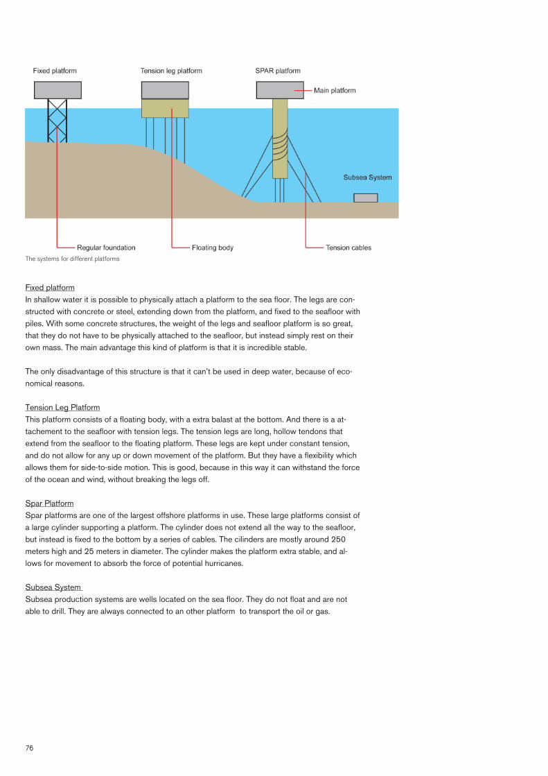
76
Fixed platformIn shallow water it is possible to physically attach a platform to the sea fl oor. The legs are con-structed with concrete or steel, extending down from the platform, and fi xed to the seafl oor with piles. With some concrete structures, the weight of the legs and seafl oor platform is so great, that they do not have to be physically attached to the seafl oor, but instead simply rest on their own mass. The main advantage this kind of platform is that it is incredible stable.
The only disadvantage of this structure is that it can’t be used in deep water, because of eco-nomical reasons.
Tension Leg PlatformThis platform consists of a fl oating body, with a extra balast at the bottom. And there is a at-tachement to the seafl oor with tension legs. The tension legs are long, hollow tendons that extend from the seafl oor to the fl oating platform. These legs are kept under constant tension, and do not allow for any up or down movement of the platform. But they have a fl exibility which allows them for side-to-side motion. This is good, because in this way it can withstand the force of the ocean and wind, without breaking the legs off.
Spar PlatformSpar platforms are one of the largest offshore platforms in use. These large platforms consist of a large cylinder supporting a platform. The cylinder does not extend all the way to the seafl oor, but instead is fi xed to the bottom by a series of cables. The cilinders are mostly around 250 meters high and 25 meters in diameter. The cylinder makes the platform extra stable, and al-lows for movement to absorb the force of potential hurricanes.
Subsea System Subsea production systems are wells located on the sea fl oor. They do not fl oat and are not able to drill. They are always connected to an other platform to transport the oil or gas.
The systems for different platforms

77
BUILDING STRUCTURESFloating information centre IJburgDue to a new residential area, called IJburg, Amsterdam needed a transportable information centre. Because fl oating is the ultimate fl exibility, Attika Architects designed a fl oating building, in 2000.
The information centre consist of three platforms all connected together into one rigid struc-ture. The three platforms fi rst went into the water seperatly and then they where pretensioned together. With this method we can create incredible large fl oating structures.
The platform is about 19 meters by 37 meters. The total area is 700 square meters. And the building is used for exhibitions for the plans of the new residential area.
The fl oating body is a pontoon, made from concrete with a expanded polystyrene (EPS) fi lling. The building is constructed with a timberframe structure.
It has a heavy foundation with a light weight building.
The fl oating information centre IJburg on transport
The fl oating information centre IJburg on its location
Basic schemes of mostly used fl oating bodies / pontoons

78
Floating Pavilion RotterdamIn the centre of Rotterdam is situated, a complex of three hemispheres, which are fl oating on the water.
The building consists of three interconnecting fl oating domes, the largest has a diameter of 24 meters. The fl oor is 46 by 24 meters. The pavilion was built by the contractor Dura Vermeer and serves as an exhibition and reception area. The location for the pavilion in the Rijnhaven is temporary, the building we be moved to different locations after a few years.
The building is very durable, due to the used materials, but also in the fl exibility (it can move be-cause it is fl oating on water). The building is heated and cooled by solar energy and the mass of the water.
The building cleans its own toilet water, and what is left is clean enough to being discharged into the surface water.
The building mainly consist of ETFE foil which is about 100 times lighter than glass. This foils is therefore ideal for fl oating buildings.
The fl oating body is made from expanded polystyrene (EPS) with a exteriour protection layer of polyurea, which is a innovative principal.
It has a very light weight foundation with a very light weight building.
Interior of Floating Pavilion Rotterdam
Floating Pavilion Rotterdam

79
Floating airport JapanThe fi rst fl oating airport was one of the largest fl oating structures on sea ever build. The project is called ‘Mega Float Airport’, and build in 2000 in Tokyo Bay, Japan.
The airport measures 121 by 1.000 meters and has been tested positively on stability and vibration by waves. Because it is so large, the structure shows less pitch and roll than a smaller one. This is because, the larger fl oating structure receiving more waves, and because the wave-length is shorter than the structure, the forces that lift the structure up and the forces that pull the structure down cancel each other out.
On open sea the airport was having some problems with the landing of the planes. The computerized landing system crashed, because the airport was moving and not staying in its position.
Therefore it is necessary that a building on the sea should have a guiding structure and a break-water structure, to keep it into place. Also the structure can resist the impact of a earthquake, because the water absorbs the vibration.
Because the results of the test model of 1.000 meters were so positive, the Japanese gouvern-ment now want to scale the length up to 4.000 meters.
The completed fl oating body
The components getting fi xed together

80
Floating citiesAccording to some people, like Koen Olthuis -the owner of Waterstudio-, fl oating cities are part of the future. He has designed a lot of different fl oating cities, with different functions. Most of his designs are still concepts, but could be build in the future. Until now the only projects that has been realised are the fl oating homes that he designed.
Watervilla De Hoef, The Netherlands
The White Lagoon, Floating Watervilla’s, Maldives
Amillarah, Floating Private Islands, Maldives
Floating Golfcourse, Maldives

(this page intentionally left blank)
81

82828282228282228

83838383838333
5 ARCHITECTURE

84 Thames River Park London, United Kingdom

85
ARCHITECTURAL RESEARCHThe architectural research consist mainly in four parts, the fi rst one are the fl oating building references, the second one are the theatre references, the third one is the theatre study and the fourth one is the application or usability of a fl oating theatre (so fi rst design).

(this page intentionally left blank)
86

87
FLOATING BUILDING REFERENCES

88
FLOATING HOUSE IMiddelburg, The Netherlands
The fl oating house (NL: Watervilla) in Middelburg is a innovative example of architectural engineering. The goal was to design a building that could replace the classic, not practical designed houseboat (NL: Woonboot) and which could stay in the water for a long time with-out much maintenance. According to the architect, fl oating is freedom and independence.
At fi rst the fl oating house was used as a exposition space to check out its behaviour in the water and promote building on water, but now it is used as a home.
Structure and materialsThe house has three levels, with a total fl oor plan of 160 m2. The structure exists of a steel frame structure with a foam insulation.
The material that is mainly used is pre-coated steel, for the inside and outside covering material. Because of the round shape of the building, steel is also a good material to use, because it has a smoother fi nish. Because the steel is pre-coated, maintenance is almost unnecessary.
Floating structureThe structure is fi xed to a fl oating body that is made from a steel air cushion system, made from six D-section hollow steel tubes with a diameter of two meters and a thickness of 10 mm. With this system the structure fl oats on the right level. The house can be rotated 120 degree, due to the system with two steering wheels. In this way the house can be orientated towards or away from the sun. The building is fi xed to the waterside with a hook, which is similar to a towbar from a car, that is connected to a ten meter long steel tube under the walkway.
Architect
Completion
Category
Herman Hertzberger
2002
Realised - Floating House
Photo of the house and a steel cable
Top view of the fl oating system, rotation in different positions
Photo of the balcony above the water Photo of the walkway (routing) Photo of the house and the other steel cable

89
Why is this building fl oating?This building is mainly fl oating so it can move (change its orientation) towards or away from the sun. This will reduce the use of energy for heating or cooling. Also this building was made fl oating to set an architectural example for new ‘houseboats’.
Floor plans of the building

90
FLOATING HOUSE II Noordwolde (Fr.), The Netherlands
Designer
Completion
Category
Cees Tadema
2007
Realised - Floating House
In Noordwolde, Cees Tadema had built a house, which is able to rotate 360 degrees, so it can orientate towards the sun. To let the building rotate easy, the building is fl oating in the water.
Structure and materialsThe main structure for the building is made from cellular concrete and wooden, which makes the building lightweight. The roof is covered with reed which is also light.The total weight of the building is 30 tons.
Different photos of the building

91
Floating structureThe fl oating structure consist of a EPS (expanded polystyrene) body, which has been put in a pond. The fl oating body is 1,6 meters high, which is enough to let the 30 tons fl oat. The house is rotating with a sleeve around the steel tube in the centre of the building. The build-ing is being balanced/levelled with three ballast spaces under de wooden deck around the building. The building is made round, which makes it easy to rotate, you can even rotate it by hand. The cables that go in and out the building are made fl exible and go into the house at the centre tube. After the building has rotated 360 degree, it has to rotate back otherwise the cables will break.
Why is this building fl oating?This building is also fl oating to change its orientation. For saving energy and for the fun of ‘sitting in the sun’ with your book in summer.
Floor plan rotation mechanism
section

92
FENNELL HOUSE Portland, Oregon, United States of America
Architect
Completion
Category
Robert Oshatz
2005
Realised - Floating House
Architect Robert Oshatz has been creating eco-friendly residences for nearly 40 years. This passive house “Fennell Residence” fl oats on Portland, Oregon’s Willamette River. This elegant designed ultra-low energy house stands out along the riverbed, and draws a lot of attention to it.
The main reasons for fl oating is to draw attention, move the building and because its cheaper then a building on land in this area.
River facade
interior

93
Street facade

94
DINNING ROOM Noordwolde (Fr.), The Netherlands
Architect
Completion
Category
Goodweather / Loki Ocean
2010
Realised - Floating Restaurant
This fl oating dining room, located in Vancouver, Canada, is designed by the architects, Goodweather Design & Loki Ocean. This building has been built for a summer fund-raiser by The School of Fish Foundation, a nonprofi t organization committed to promoting sustainable seafood. The semi-enclosed space fl oats on over 1700 recycled plastic bottles. The project intends to bring attention to the abundance of plastic litter fl oating in the oceans, but also suggests a possible use for such waste. Due to budget and time constraints the design of the structure remains a conventional post and beam assembly allowing the framing to serve as fi nish.
Why is this building fl oating?This building is mainly fl oating to make people aware of sustainability issues, like sustainable seafood, and the environmental pollution of the ocean due to plastic bottles. Recycling them in a fl oating building is a good way to show the possibilities of a waste material.
It also shows an architectural experience of dining on the water, when a ship moves by, the whole building moves up and down and reminds you that you’re on the water. Also because the fl oor is transparent, you can see the plastic bottles.
Photo of building
Bottles

95Drawings and diagrams of building

96
THE FLOAT Marina Bay, Singapore
Architect
Completion
Category
D.S.T.A. Ministry of Defence (Singapore)
2007
Realised - Floating Stadium
The Float at Marina Bay is the world’s largest fl oating stage. It is located on the waters of the Marina Reservoir, in Marina Bay, Singapore. The project is designed by the D.S.T.A., (Defence Science and Technology Agency), a statutory board under the Ministry of Defence of Singapore.
The fl oating stadium is being used for events on the water, and sports, concerts and cultural performances (like parades).
Structure and materialsThe fl oating platform is entirely made of steel. The tribune is made from steel and concrete and can hold up to 30000 people. It is a shame that the tribune is not fl oating.
Floating structureThe fl oating structure is made from a hollow steel structure and measures 120 metres long and 83 metres wide. The platform can hold up to 1070 tonnes, which is a lot of weight. The platform is made of smaller pontoons, which are connected together, in this way a lot of dif-ferent shapes can be made.
The platform stays in place due to six foundation poles. It is connected with rollers, so it can move up and down. The platform can be reached due to three gangways.
Floating platform in front of the tribune
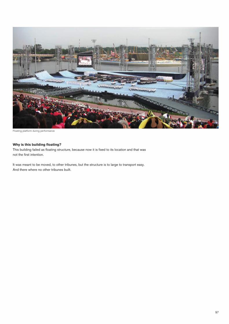
97
Why is this building fl oating?This building failed as fl oating structure, because now it is fi xed to its location and that was not the fi rst intention.
It was meant to be moved, to other tribunes, but the structure is to large to transport easy. And there where no other tribunes built.
Floating platform during performance

98
THAMES RIVER PARK London, United Kingdom
Architect
Completion
Category
Gensler Architects
2011
Design - Floating Public space
Gensler architects has made a design for a fl oating public space on the Thames River in London. The fl oat is designed along the north shore from the Blackfriars bridge to the Tower of London, the river park will be the fi rst of its kind along the Thames, providing new views on the buildings around the river. The fl oating river park will be around 800 meters long and 20 meters wide. It will serve as a long horizontal connection between many landmarks that are otherwise connected with overcrowded and diffi cult to navigate streets.
The structure is fast-tracked to be completed in time for next summer’s 2012 Olympic games in London.
Why is this building fl oating?This building is mainly fl oating to make a connection between the landmarks. In london is a mayor space problem, there is not a lot of a space available and when it is available it is very expensive. Also the demolishing of the existing buildings and then built new buildings would also take up to much time.
The river is a existing horizontal connection which is now not optimal used. Because the river is already property of the government, building on it save a lot of money, because they don not have to buy a new piece of land.
Also an other reason to make it fl oating is that it can be removed from its location, so when it is not necessary anymore or people don not like it anymore, than it can be removed without leaving a scar in the city its urban plan.
Render of the Thames River park

99
Renders of the Thames River park
Connection sketch

100
FLOATING ISLANDSSeoul, South Korea
Architect
Completion
Category
Kim Tae-man
2011
Realised - Floating Island
FLOATING ISLAND
In 2011 the world’s largest fl oating island was built on the Han River in Seoul, South Korea. The fl oating island is designed by architect Kim Tae-man from H Architecture. The fl oating island consists from three islands that are linked together by twenty-three weather-proof chains.
The buildings are fully all powered by solar energy and therefore very environment friendly. An other sustainability issue is that there are sometimes fl oods in Seoul, but because they are fl oating, the islands while rise and fall with the water levels, this saves a lot of embodied energy.
A high tech tracking system will alert a controller if the islands will fl oat too far from their home site, due to highly changing water levels.
The buildings are three storeys high, which is conventional to a fl oating building. The build-ing costs are around 65 million euro and has a building area of 5400 m2.
The buildings are used to host international conventions, cultural performances and exhibi-tions.
Floating structureThe building is supported by 24 giant air-bags, the building weighs 2000 tons, but can sup-port building facilities up to 6400 tons. The island will be harnessed by chains to a 500 ton concrete block to keep it in place.
Why is this building fl oating?The building is fl oating to show to the rest of the world that they can built great building on water, with a cultural function.
Also for sustainability issues it sets an example to others of how to deal with sustainability and the dangers of fl ooding, due to climate change.
Photo of Floating Islands

101
Photos of Floating Islands

102
(this page intentionally left blank)
103
THEATRE REFERENCES
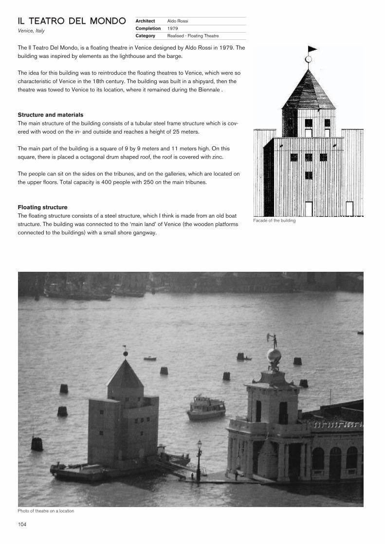
104
IL TEATRO DEL MONDOVenice, Italy
Architect
Completion
Category
Aldo Rossi
1979
Realised - Floating Theatre
The Il Teatro Del Mondo, is a fl oating theatre in Venice designed by Aldo Rossi in 1979. The building was inspired by elements as the lighthouse and the barge.
The idea for this building was to reintroduce the fl oating theatres to Venice, which were so characteristic of Venice in the 18th century. The building was built in a shipyard, then the theatre was towed to Venice to its location, where it remained during the Biennale .
Structure and materialsThe main structure of the building consists of a tubular steel frame structure which is cov-ered with wood on the in- and outside and reaches a height of 25 meters.
The main part of the building is a square of 9 by 9 meters and 11 meters high. On this square, there is placed a octagonal drum shaped roof, the roof is covered with zinc.
The people can sit on the sides on the tribunes, and on the galleries, which are located on the upper fl oors. Total capacity is 400 people with 250 on the main tribunes.
Floating structureThe fl oating structure consists of a steel structure, which I think is made from an old boat structure. The building was connected to the ‘main land’ of Venice (the wooden platforms connected to the buildings) with a small shore gangway.
Facade of the building
Photo of theatre on a location

105
Why is this building fl oating?This building is fl oating, because this is Venice and there is no good ground for a foundation. Also it needed to be transported to different locations for different festivals and transporting on water is one of the most easiest ways especially in Venice.
Floating also fi ts to the ‘water theme’ of the city, almost all transport is done by boat, so why not build a building on a boat?.
sections of the building
Floor plan of the building

106
DE HANGAARKatwijk, The Netherlands
Designer
Completion
Category
Bernhard Hammer
2007
Realised - Theatre
The Hangar Theater was originally an aircraft hangar at a former military airfi eld Valkenburg between Wassenaar, Katwijk and Leiden. On this historical site a unique concept is created.
The tribune, where the public is seated (contains 1100 seats), is rotating around from one stage to the other. Also the old runway of the airport is part of the stages. This concept of a rotation theatre and the relation with the context is a new concept for theatres.
The play that is performed in this theatre is called; ‘De soldaat van Oranje’ (the soldier of orange), this is about a hero of the second world war (WWII), which also fi ts in the context of the military airfi eld.
This new concept of creating real scenes with real materials (or fi lm sets) creates a new dimension of theatres. People have to imagine less, and maybe this can attract younger people, which are used to fi lm technology.
Building the concept model

107
Floor plan of the building
Photos of the stage during building and fi nished

108
FELIX MERIX THEATERAmsterdam, The Netherlands
Architect
Completion
Category
Jacob Otten Husly
1787
Realised - Theatre
The Felix Merix Theatre, Amsterdam, The Netherlands, is designed by Jacob Otten Husly and built in 1787. It is originally built as a society building, to stimulate the ideas of The Enlightenment on science and art. A lot of scientifi c research has been done in the building, next to the performances of different kinds of art, like painting and music.
The theatre room has a ecliptic shape and is famous in the Netherlands because of its acoustics. The performances that are performed in the theatre room are music or cabaret, but no large drama/Broadway shows because there is not a lot of space for the stage.
Floor plans of the building

109Different elevations and sections

110
(this page intentionally left blank)
111
THEATRE STUDY

112
THEATRE TYPOLOGIES
A theatre is a space where a performance takes place. A building specialized for presenting performances. The main parts of a theatre are the tribunes for the audience and the scene or stage.
These two parts mainly determine the ap-pearance and main layout of the theatre. Therefore to determine the typologies of theatres, the relation (position) between the stage and the tribunes is most important.
Mainly we can determine four different types of theatres: - Arena or theatre-in-the-round stage; - Theatron / prescenenium stage; - Proscenium-arch / picture-frame stage; - Spatial space (stage).
Arena or theatre-in-the-round stageThe arena is the most elementary theatrical situation. People assemble a closed ring around a fl at piece of ground to witness a event. For larger groups, natural slopes in the landscape provide rising ground to provide a good view angle. Most simple form is people sitting around a campfi re with one person standing telling a story.
Theatron / prescenenium stageThe word theatron, which is Greek, means a space for watching. This is very similar to the arena, except the audience is now arranged in a segment of a circle and there is a larger stage, with a area for a orchestra and a area for the actors (proscenium). A big differ-ence between a Greek and Roman theatre is that the Greek theatre is built on a natural slope and the Roman theatre is build on a fl at piece of land, and there is a building structure under the audience.
Typologies

113
Proscenium-arch / picture-frame stageThe stage of this type is enclosed on three sides and the audience is allowed to view trough a frame opening on the fourth side.So it looks like looking trough a picture frame. There are also gallery levels to pro-vide a good view.
Spatial space (stage)This type was invented to reunite the stage with the auditorium / tribune, to form a single whole again. The gallery levels where removed again. The performance could go through the whole building. More different kind of theatres should be able to perform in this type of theatre.
Floor plan and section Greek theatre
Floor plan and section Roman theatre

114
Timeline of tribunes1. The last 2000 years, the shape of the trib-unes has changed, First around the year 0, the main shape was the shape of the Greek and Roman theatres. The basic shape of these theatres is a segment of a circle. The arena type, was also used during this period, but less common. One of the most well know theatres is the amphitheatre in Rome, called the Colosseum. The Colosseum is a mix between the arena and the roman thea-tre. The shape is called the roman elliptical theatre.
2. Later on, more U-shaped theatre arises, these theatres had the scene in the middle and where also used for ‘Roman’ games, like circus games and chariot racing.
3. During the Renaissance period the theatres where more focussed on the drama scenes. Mostly the theatres were three sto-ries high, and built around an open space at the centre. The shape had a overall rounded appearance. The theatres where rather small around 500-1000 people could be seated on the tribunes.
4. Since 1876 the V-shape is introduced, this is a more easy to build shape then the Renaissance shape. Also the amount of spectators can be increased very simple and the shape gives a optimal viewing angle. This shape is nowadays the most used shape for theatres.
Timeline tribunes

115
Timeline of stages1. The Greek and Roman theatres had a very basic square shape. At the back and on the sides was the scene building, where all the facilities of the theatre where located. The roman theatre had a large painting at the back of the theatre, which was the back-ground for the play.
2. During the Renaissance the people started to develop the depth of the theatre. The square stage was opened up and build-ings where placed on it so the stage had for example the appearance of a street. In this way the people needed less imagination during the play.
3. Around 1750, people wanted a more changable stage. Because they where newer technologies, the introduction of the Tellari stage was possible. Here the ‘pre-coulisses’ could be changed during the breaks of the play.
4. Around 1770, the Tellari stage made place for the coulisse stage. During small breaks in the play, the background could be changed very easy. They used curtains to close the stage and when the curtains reopened, the stage was changed. This is nowadays the most used type of stage.
5. The round horizon is a stage that is mostly used for one-man-shows, like cabaret, or for television shows.
6. Nowadays the new developments are rotating tribunes, with multiply stages or sliding staged in front of a tribune. This kind of stage is probably the best choice for a fl oating theatre, because it has the highest fl exibility.
Timeline stages

116
(this page intentionally left blank)

117
USABILITY FLOATING THEATRE

118
Different kind of movements of a fl oating object. Horizontal and vertical movement and rota-tion of the object.
Aspects of fl otationMy study to the aspects of fl otation gave simple results, but the advantages of these aspects to a building are great. Horizontal movement (x and y-axis), is probably the most simple and easiest to use aspect. The fl exibility that it creates is very large and gives great possibilities for a fl oating theatre, for example it can be used for changing the stages/scenes or trans-porting the theatre into a other place between the scenes.
Vertical movement (over the z-axis) is the second aspect. This aspect is always there, be-cause the building is always immerged into the water and due to the movement of people in the building and the effect of the waves on the building. This aspect can also be used when I choose to use a vertical (lift) stage, the stages can then sink into the water. This is probably not the best choice, because then the sea should be very deep on that location.
An other aspect is rotation (around the z-axis) this is an interesting aspect to use, the tribune can be rotated around the different scene or the other way around. Also it can be used to orientate the tribune towards a background (the harbour, the horizon or the boulevard) or towards the different scenes.
The last aspect is skewing (rotation around the x and y-axis) this aspect will probably always occur, due to the effect of the waves. This can provide an extra input to the drama of the theatre, but can also give problems like seasickness.
Horizontal displacement
Rotation
Vertical displacement
Skewing

119
Usability of horizontal displacement and rotation

120
Creating perspective / 3D theatre (form study model)
Creating perspective / 3D theatre (form study model)

121
Usability of skewing
Usability of skewingUsability of vertical displacement

122
vertical movement of a platform, to rearrange space
DESIGN IDEAS FOR FLOATING PARTS
horizontal movement, to expand a space
rotation, change of routing, closing of a section for public

123
vertical movement, close or access fl oor up or below, due to tidal change
vertical movement, change daylight or ventilation of a space

124
horizontal and vertical movement, transport a scene into a public area, so peo-ple can access it after the show, and re-live the show.and the use of a pulley system which can be opened due to tidal difference or us of ballast

125
vertical movement, due to tidal difference, recreate space with wall movement
vertical movement, with ballast tanks, recreate space, creating objects

126
Movements of different functionsThere are also other facilities necessary for a theatre like; toilets, a bar, foyer, technical space, backstage, dressing rooms and so on. These functions will probably be more fi xed, like when built on land. It is probably not very practical to have a fl oating toilet, that moves up and down.
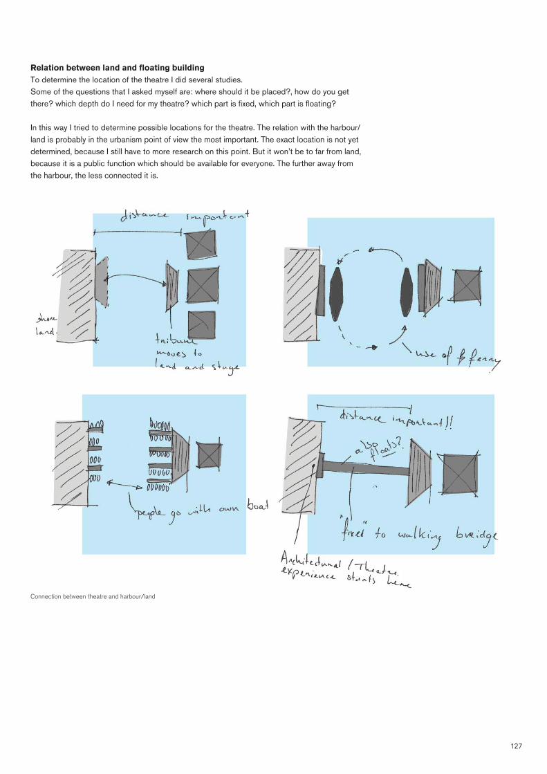
127
Relation between land and fl oating buildingTo determine the location of the theatre I did several studies. Some of the questions that I asked myself are: where should it be placed?, how do you get there? which depth do I need for my theatre? which part is fi xed, which part is fl oating?
In this way I tried to determine possible locations for the theatre. The relation with the harbour/land is probably in the urbanism point of view the most important. The exact location is not yet determined, because I still have to more research on this point. But it won’t be to far from land, because it is a public function which should be available for everyone. The further away from the harbour, the less connected it is.
Connection between theatre and harbour/land

128
Functions and zones of the theatre

129
(this page intentionally left blank)

1301311113013030130133003030303003130131301303030000011313031313033330000000301113333033013013013030000000130003333313300000003333130000303031313033000000131113130130130111111130133133330300001111111313331330011113133333333033030001113333333333333330003333333333300113113113333333333333011111313333333300000111131313133333330300311113333330011333300011133333030013330033333131333333333003333013311333300

13113133333333131313131133111333331133333331133333333333333311333333333333333333311333333333
6 URBANISM

132
(this page intentionally left blank)

133
LOCATIONThe Harbour is located in Scheveningen, The Hague, The netherlands and situated in a block between three roads and the North Sea:
The three roads are; Houtrustweg, Doctor Lelykade and Schokkerweg.
Location harbour area Scheveningen

134
Location harbour area Scheveningen

135
ROUTING/INFRASTRUCTURE OF LOCATIONThe routing to the location is shown in the fi gure below. If we look at the map, we can see that the location has a good infrastructure, but during the summer when the people want to go to the beach, the infrastructure is not suffi cient and also there is not a lot of parking space avail-able. This is general problem in The Hague and until now, they did not succeeded in getting rid of this problem.
In the image the colours are representing the following ways of transport, the dots are parking space or bus and tram stops. - Blue: Boats; - Red: Cars; - Purple: Walking; - Green: Bus and Tram; - Orange: Suggestion for bridges.
I also did two suggestions to improve the infrastructure of the harbour, by adding bridges (orange lines).
Location with routing/infrastructure

136
Global dimensions of harbour (800 x 1500 m)
HARBOUR DIMENSIONS

137
WATER DATADepths of the sea - Beach around 2 meters - Coast line around 4 meters - Inside harbour 7-8 meters - Outside harbour (sailing route) 9-10 meters - Outside harbour (1 km) 13-14 meters
Map of depths of the sea

138
Location map with depths of the sea and harbour
Depths of the seaThe depth of the water is an important feature for fl oating buildings. Close to the land, where the swimming area is, the water is not that deep around 2 to 3 meters. Just outside and inside the harbour, the depth is between 7 and 8 meters, which is quite deep and has great possibili-ties for a building. A depth of 7 meters means a maximal upward force of 10,3 x 7 = 75 kN/m2, this is quite large for a building.
When a building is designed the total weight should be calculated to get an idea of how much depth is necessary for the building. Four potentiation locations are shown in the map below (black cross-dot mark).

139
Wave heightThe most important data of the water are the height of the waves which are mostly around 2 meters further away on sea (so not close to my location).
DATA:Wave height between 0 and 2 metersAll directions, due to currents (wind and temperature) and tides Most are in the west-region (south-west to north-west)
Tide difference 1,5 - 2 meters (1,7 m)
The currents of the ocean / sea are shown in the images on this page, this is the main factor for the behaviour of the waves.

140
URBAN GUIDELINES FOR THE DESIGN

141
FUNCTIONS
Circus Theatre (1500 persons)
Appel Theatre (500 persons)

14214214242421421421424242142142142142142422224224224222222

143143143443333331143143143144311143143343411
7 CASE STUDY

144
(this page intentionally left blank)

145
CASE STUDY: REVOLT HOUSE7As a case study for my graduation project, I am also working on the ReVolt House project. The ReVolt House is the entry of the TU Delft for the Solar Decathlon Europe 2012.
The Solar Decathlon is a competition between universities from all over the world, which design and build a self-suffi cient house, powered only by solar energy, with the implementation of technologies that will give the house an effi cient use of its resources.
The Revolt House team is a multidisciplinary team from the TU Delft, with various expertise and experiences in the fi elds of architecture, climate design, energy production, sustainability, prod-uct development, innovation, design of construction, engineering and the built environment.
My work for the ReVolt House focuses on the fl oating structure.
Interior impression of the ReVolt house
Floating structure and rotationThe house will rotate for one reason amongst others because of climatic and energy aspects. One side of the house will have a closed facade which in summer will continuously face the sun in order to shade the interior and minimize the solar heat gain inside (lesser cooling). We call this closed part of the house the “heat shield” where a passive solar cooling system will be integrated. In winter when the suns’ altitude is lower, the “open” glass facades of the house will continuously face the sun. This will generate a solar heat gain for the interior (passive heating) which requires less energy for an actual heating system. Since the house is fl oating frictionless on water the rotation won’t require much of an effort.
DIFFERENT FLOATING STRUCTURESGot get the most effi cient shape for the ReVolt House, we tested different shapes on its behav-iour, we did this mostly with computer simulations.
For these simulations we used the program Orca3D which is a plug-in for the design program Rhino. This program is mainly used to calculate boat structures (hull design).
Impression of the ReVolt house

146
First calculationsTo get familiar with the theory of fl oating and the computer program, we fi rst made some simple calculations and tested different shapes.
We fi rst put a load of 200 kN (20 ton) in the centre of the fl oating body. Then we calculated how much the body would sink. We tested three different shapes, a fl at shape, a hollow shape and a shape with a thicker edge, fl at hollow shape.
The fl at hollow shape was the best, because the second test with the load off centred showed that it was more stable. Also because the loads of the building are coming down on the edge, the forces are directly transported to the water, in this way the beams in the fl oor can be thin-ner.
Calculation results fi rst orca calculation
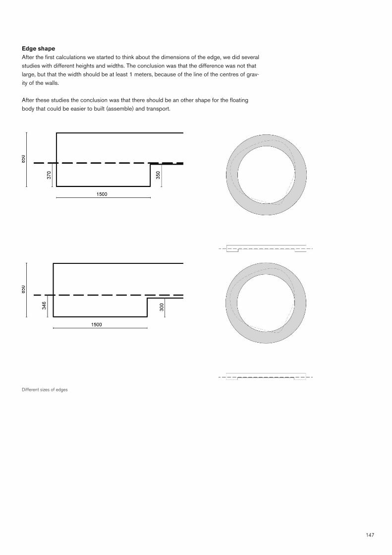
147
Edge shapeAfter the fi rst calculations we started to think about the dimensions of the edge, we did several studies with different heights and widths. The conclusion was that the difference was not that large, but that the width should be at least 1 meters, because of the line of the centres of grav-ity of the walls.
After these studies the conclusion was that there should be an other shape for the fl oating body that could be easier to built (assemble) and transport.
Different sizes of edges
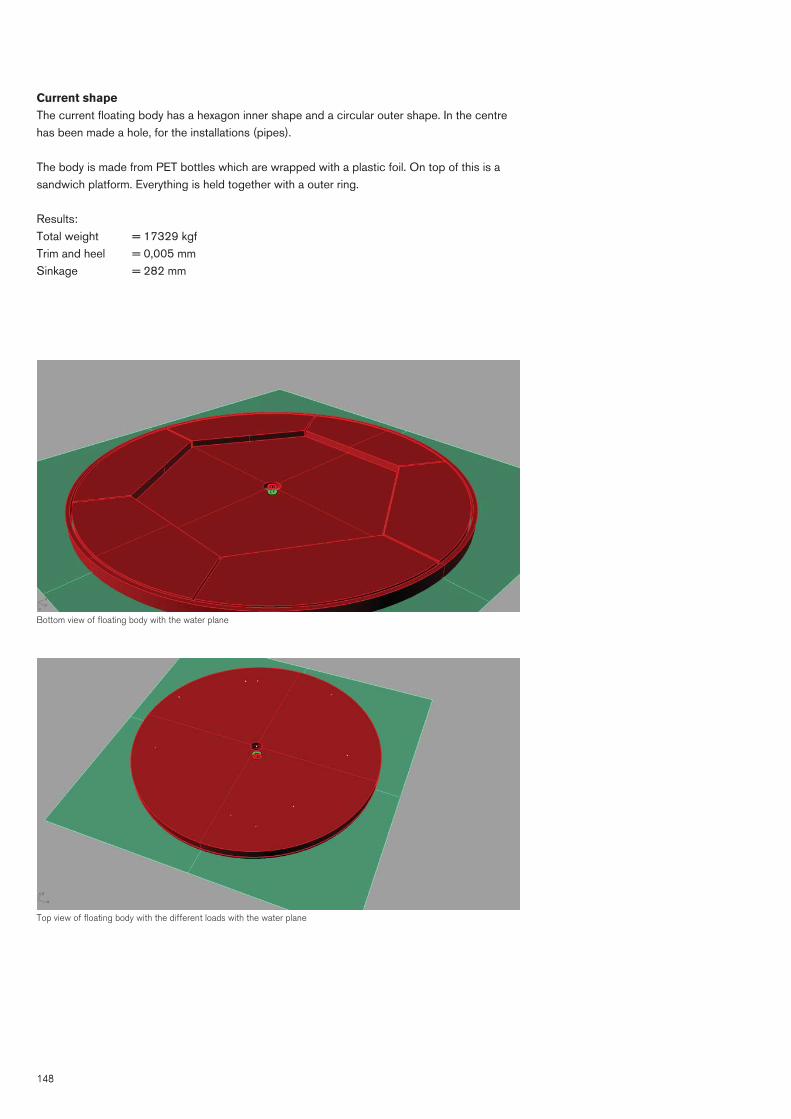
148
Current shapeThe current fl oating body has a hexagon inner shape and a circular outer shape. In the centre has been made a hole, for the installations (pipes).
The body is made from PET bottles which are wrapped with a plastic foil. On top of this is a sandwich platform. Everything is held together with a outer ring.
Results:Total weight = 17329 kgf Trim and heel = 0,005 mm Sinkage = 282 mm
Bottom view of fl oating body with the water plane
Top view of fl oating body with the different loads with the water plane

149
Location of the point loads on the fl oating body
NOTE:Due to a lack of fi nancial support, team TU Delft is withdrawn from the Solar Decathlon Europe 2012, therefore the construction of the Revolt House will not start, and the project will remain a concept.

15015011501150150150150150150150550150501501551515015001501 000015015015015000000

15115151151151151151115111511515115111151 115115111111511151111551 11555
8 CONCLUSIONS

152
(this page intentionally left blank)

153
mooring pole Shoebox principal (aircushion supported structure)
ENGINEERINGHydrostaticsMost important thing to know for design: - Building should be in balance on its deadweight; - Designed according to shape and/or weight stability; - Light weight structure vs. Heavy weight fl oating body is better for static stability; - Vertical movement of 1,7 meters due to tidal difference.
HydrodynamicsMost important thing to know for design: - The water around the fl oating building must be considered as an irregular wave fi eld, but not a breaking water, so more or less calm water. - Two parameters of the wave fi eld are important for the design, the signifi cant wave height and wave period. - The condition for the dynamic stability is that the natural frequency of the building, is different from the wave period that is occurring. - The natural frequency should be tested for the relevant degrees of freedom (the heave and roll motion). - As can be shown the breaking in the harbour of Scheveningen has a Iribarren parameter of larger than 5, this means it is surging. The waves there are not that much disturbed that they create all kind of different vibrations, the waves are more or less calm.
Problems for dynamic stability that could occur: - The stages that are design to be fl oating should be able to width stand the motion that is generated due to the effect of waves, in a way that the performers are able to perform and not are getting seasick.
Note:The effect of the waves is not as large as expected earlier, the location already gives a great cover to the larger waves. The exact infl uence of the waves needs to be calculated in a further stadium.
Solutions could be: - Temporary fi xing to a mooring pole or a fi xed building, when it is in place; - Use of larger and/or heavier structures (improve ofweight and shape stability); - Shoebox principal (aircushion supported structure) - dr. ir. J.L.F. van Kessel (TU Delft) - Use of catamaran structure (almost same as shoebox); - Use of cables, with weight (offshore technology) - Use of a more effi cient shape like a ‘axe bow’ shape (used on boats); - Use of a temporary breakwater system, which can be used during larger waves.

154
ARCHITECTUREThe buildings are mostly built on water for sustainability and fl exibility reasons, but also for economical reasons (like expensive ground)
The main parts of a theatre are the tribune and the stage, but also other facilities like second stages, toilets, restaurant/bar, foyer, dressing rooms and the technical rooms should not be forgotten in the design.
The V-shape is the most effi cient way to build and easier to design.There are different options/aspects for a fl oating theatre; horizontal movement, vertical move-ment, rotation and skew. The horizontal movement and rotation have the greatest potentials for a fl oating theatre.
URBANISM (LOCATION) The location to the infrastructure is good in the afternoon and beginning of the evening. In the summer the location is extra crowded, but still good to reach with the public transport.
Potential locations are close to the harbour, in this way the relation between the harbour and the building is also the strongest. People should not have to travel a long time from the harbour to the building.
POSSIBLE DESIGNSI made sketches for two different options, the big problem that occurred was that it is hard to get a solution for changing the stages, when the whole theatre is indoor.
The fi rst on is a amfi -theatre with a fl oating tribune and fl oating stages and the rest of the facili-ties and public space on a fi xed overhanging structure. The second one is a closed theatre, with a large space behind the main stage that could be used to store the stages.

155
First idea sketch
Second idea sketch
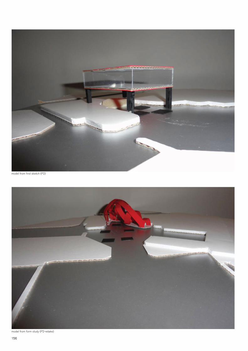
156
model from fi rst sketch (P2)
model from form study (P2-retake)

157
Study model scale 1:500

1581581158115815815815815815815855815581155151581588151 888815815815815888888

15915159159159159159991151159115159159999151 91591599111511 915111551 91555
9 LITERATURE

160
(this page intentionally left blank)

161
Books / ArticlesAerts, J.; Major, D.C.; Bowman, M.J.; Dircke, P.; Aris Marfai, M., (2009), Connecting delta cities: coastal cities, fl ood risk management and adaptation to climate change, VU University Press
Curtis, W.J.R., (2009), Modern Architecture since 1900, Phaidon Press London
Dokkum, K. van, (2003), Ship Knowledge: A Modern Encyclopedia, Dokmar, Enkhuizen
Derrett, D.R., (2006), Ship stability for masters and mates, sixth edition, Butterworth-Heine-mann, Oxford
Dijk, W., van, (2003), Drijvend wonen, Metro
Duin, L. van, Barbieri, S.U., Geerts, F., (1999), Plandocumentatie Theaters, Delft: University Press, Delft.
Dircke, P., Aerts, J.C.J.H. & Molenaar, A., (2010), Connecting Delta Cities. Sharing -Knowledge and working on adaptation to climate change, Rotterdam: City of Rotterdam.
Eyres, D.J., (2007), Ship construction, sixth edition, Butterworth-Heinemann, Oxford
Heide, N., ter, (2009), Betoniek: Spelregels voor 100 jaar, Uitgeverij Æneas
Journee, J. M. J., Massie, W. W. (2001), Offshore Hydro Mechanics, (First Edition), Delft Uni-versity of Technology, Delft
Kamerling, M.W., (2005 ), Het ontwerpen van pontons voor drijvende gebouwen, Delft Univer-sity of Technology, Delft
Keuning, Olthuis, K. (2010), Float: building on water to combat urban congestion and climate change, Frame Publishers, Amsterdam
Kleijer, E. (2004) Instrumenten van de architectuur, een compositie van gebouwen, SUN, Amsterdam
Knabb, R.D., Rhome, J.R., Brown, D.P., (2005), Tropical Cyclone Report: Hurricane Katrina, National Hurricane Center
Leupen, B. ea. (2005) Ontwerp en Analyse. (Rotterdam) 010
Neufert, P., Neufert, E., (2002), Architects’ Data (3rd Edition), Blackwell
Ross, P., (1997) The Relationship between building structure and architectural expression: implications for conservationand refubishment. In: Stratton M. Structure and Style. London: E & FN Spon.
Schelle, B., Wimmer, F., (2009) Detail: Issue 3 - Music and Theatre, Institut für internationale Architektur-Dokumentation GmbH & Co. KG, Munich.
Sear, F., (2006), Roman Theatres: An Architectural Study, Oxford University Press
Stevens, S.C., Parsons, M.G., (2002), Effects of Motion at Sea on Crew Performance: A Sur-vey, Marine Technology Magazine
Ulm, F.J., (2009), MIT engineers fi nd way to slow concrete creep to a crawl, Internet source: http://web.mit.edu/newsoffi ce/2009/creep-0615.html
162
Watkin, D., (2001), De westerse architectuur ‘een geschiedenis’, Uitgeverij Sun Nijmegen
Zijlstra, H., (2009) Analysing Buildings from Context to Detail in time: ABCD research method.Amsterdam: IOS Press.
VideosDiscovery Channel: Build it Bigger, Season 5 Episode 6: Amsterdams Futuristic Floating City
Discovery Channel: Mega Engineering, Season 1 Episode 3: City At Sea
InternetAttika Architecten, http://www.attika.nl
Deltasync, http://www.deltasync.nl
Drijvende Stad TU Delft, http://tudelft.nl/actueel/dossiers/archief/drijvende-stad/
Dutch docklands, http://www.dutchdocklands.com
Ecoboot, http://www.ecoboot.nl
MIT University, http://web.mit.edu/newsoffi ce/2009/creep-0615.html
Waterstudio (Koen Olthuis), http://www.waterstudio.nl
Wikipedia encyclopedia, http://www.wikipedia.org
Student ThesisKuijper, M., (2006), De drijvende fundering een stabiele basis voor waterwonen in de 21ste eeuw, TU Delft Faculty of Architecture, Delft
Winkelen, M., van, (2007), How high can you fl oat?, TU Delft Faculty of Architecture, Delft

163
Disclaimer: All images, concepts and designs in this document are property of the author (Theo Mestemaker) or their respective owners copying for
something else then educational purposes is not allowed.