Coal Gasification Based DRI Solution for Indian Ironmaking
10
Page 1 17 th Annual International Steel Seminar and Exhibition Kolkata 2010 Coal Gasification Based DRI Solution for Indian Ironmaking By: Rob Cheeley, Sales Manager Markus Leu, Plant Sales Manager Midrex Technologies, Inc. Introduction As one of the world’s most vibrant and growing economies, India has a strong steel demand for infrastructure, construction, and consumer goods. From 1998-2008, its steel demand grew at nine percent per year. To feed this demand, steel production has grown from less than 10 million tons (Mt) in 1980 to over 55 Mt in 2008, as shown in Figure 1. Figure 1 India Steel and DRI Production Sources: WorldSteel and Midrex Technologies There are ambitious plans to increase the country’s steel production, with expansion plans to reach 250 Mt by 2020. 0 10 20 30 40 50 60 1980 1984 1988 1992 1996 2000 2004 2008 Million tons Steel production DRI production
-
Upload
khangminh22 -
Category
Documents
-
view
0 -
download
0
Transcript of Coal Gasification Based DRI Solution for Indian Ironmaking

Page 1 17th Annual International Steel Seminar and Exhibition Kolkata 2010
Coal Gasification Based DRI Solution for Indian Ironmaking
By:
Rob Cheeley, Sales Manager Markus Leu, Plant Sales Manager
Midrex Technologies, Inc. Introduction As one of the world’s most vibrant and growing economies, India has a strong steel demand for infrastructure, construction, and consumer goods. From 1998-2008, its steel demand grew at nine percent per year. To feed this demand, steel production has grown from less than 10 million tons (Mt) in 1980 to over 55 Mt in 2008, as shown in Figure 1.
Figure 1
India Steel and DRI Production
Sources: WorldSteel and Midrex Technologies There are ambitious plans to increase the country’s steel production, with expansion plans to reach 250 Mt by 2020.
0
10
20
30
40
50
60
1980 1984 1988 1992 1996 2000 2004 2008
Mill
ion
tons
Steel production
DRI production

Page 2 17th Annual International Steel Seminar and Exhibition Kolkata 2010
Approximately 58 percent of India’s steel is currently produced in electric furnaces. Given the lack of domestic scrap and the good availability of natural resources like iron ore, coal and natural gas, direct reduction has provided much of the iron units required for Electric Arc Furnace (EAF) steel production growth. Direct Reduced Iron (DRI) production has increased tremendously since 1980, from essentially zero to over 21 Mt in 2008, as shown in Figure 1. Of the total DRI production in 2008, 74 percent was produced from coal and 26 percent from natural gas. India is now the world’s largest producer of DRI. Currently, there are two primary means of DRI production in India: small-scale rotary kilns using local coal and iron ore lump, and large-scale shaft furnace plants using natural gas and iron oxide pellets and lump. In recent years, almost all the growth in DRI production has been due to the installation of rotary kiln facilities and there are now over 350 of these plants. Many are small-scale and it is believed that over 100 have capacities from 10,000-20,000 tpy. There are only seven natural gas-fired shaft furnace plants (including six MIDREX® Direct Reduction Modules), but they produce 1/4 of the total DRI in India. Future Steelmaking Growth For India to grow its steel production significantly, what are the options? Direct reduction using coal-fired rotary kilns or natural gas-fired shaft furnaces are logical choices. Rotary kiln DRI capacity has been installed because it makes use of domestic iron ore and coal, but there is a limit to the growth of this technology because rotary kilns cannot be built larger than about 200,000 tpy. Thus, it is probably not feasible to build a steel mill to produce one million tons per year or more via this route. Also, there are product quality issues because of the use of lump ore and coal with high levels of ash and sulfur. Direct reduction plants using natural gas would be an ideal choice, but there is little additional natural gas available for further expansion. Another possibility is the installation of conventional blast furnace/basic oxygen furnace technology, but this requires the importation of coking coal or coke, since only about five percent of India’s coal reserves are coking quality. Also, there may be environmental issues and the capital cost can be high. The Gasification/MIDREX® Option An alternative option generating significant interest in India is the use of a coal gasification plant in combination with a MIDREX® Direct Reduction Plant. The coal

Page 3 17th Annual International Steel Seminar and Exhibition Kolkata 2010
gasification plant would use local Indian coals to generate a synthesis gas (or syngas) that can be an acceptable reducing gas source for producing DRI in the MIDREX Plant. Coal Gasification There are three general types of coal gasifiers: fixed bed, entrained flow, and fluidized bed. All three technologies are based on partial oxidation (gasification) of a carbonaceous (carbon containing) feed material.
The general partial oxidation reaction is: 2 CHn + O2 -------> 2 CO + n H2
In addition to the desired CO and H2, the syngas exiting a gasifier also contains CO2, H2O, CH4, H2S, NH3, and particulates. If a fixed bed gasification technology is utilized, the syngas will also contain aromatic organic compounds. While each of the gasifier types can make an acceptable reducing gas for a MIDREX DR Plant, the fixed bed and fluidized bed technologies are the preferred choice for India because they can accommodate the high ash domestic coals. The leading fixed bed process is the Lurgi Gasification process, licensed by Lurgi Clean Coal Technology Company. The Lurgi Gasification technology is well-proven, with over 102 gasifiers in commercial operation worldwide, the earliest of these built in 1955. Eighty of these units are deployed in South Africa, using high ash coals very similar to Indian coals. Lurgi Coal Gasification Process In the Lurgi Gasification process, coal is gasified at elevated pressures by reacting with high pressure steam and high purity oxygen to produce a syngas suitable for the production of fuels and chemicals. The gasifier operates at a temperature below the ash melting point so the coal ash is discharged from the gasifier as a solid. Because of this low operating temperature, the Lurgi Gasification process requires significantly lower quantities of oxygen than the entrained flow gasification processes which melt the ash. The syngas exiting the gasifier is hot, dirty, and contains a significant amount of non reducing gas components. Downstream of the gasifier, the syngas is cleaned and conditioned to remove most of the undesired components, many of which are saleable byproducts that can be used as petrochemical plant feedstocks.

Page 4 17th Annual International Steel Seminar and Exhibition Kolkata 2010
Figure 2 contains a simplified process flowsheet for combining the Lurgi Coal Gasification technology with a MIDREX Plant and Figure 3 shows Lurgi gasifiers at the Sasol Plant in Secunda, South Africa.
Figure 2
Simplified Lurgi Gasification Plant + MIDREX Plant Flowsheet

Page 5 17th Annual International Steel Seminar and Exhibition Kolkata 2010
Figure 3
Lurgi Gasifiers in Secunda, South Africa
The following table summarizes the major characteristics of the Lurgi Gasification Plant.
TABLE I
Characteristics of the Lurgi Gasification Plant Operating pressure • 20-40 barg Feedstocks / Utilities • Lump coal (5-50 mm)
• Oxygen (approx. 99 mol%) • High pressure (H.P.) steam
Gas Cleaning & Conditioning • Hot syngas is cleaned and cooled by a direct contact water scrubber, followed by indirect air cooling and water cooling
• Trace components, most of the sulfur (H2S), and a significant amount of the CO2 are removed by a Lurgi Rectisol® unit at the tail end of plant
• Sulfur is recovered in an OxyClaus® process with Claus tail gas processed in an LTGT® process, achieving >99% sulfur recovery.
Produces valuable and saleable co-products
• Phenols • Ammonia • Coal oil

Page 6 17th Annual International Steel Seminar and Exhibition Kolkata 2010
• Elemental sulfur • Low pressure (L.P.) steam
MIDREX® Direct Reduction Plant The high pressure syngas exiting the Lurgi gasification plant contains approximately 85 percent H2+CO, 2.5 percent CO2, and 12.5 percent CH4. The H2/CO ratio is about 1.6, which is the same as used in a natural gas-based MIDREX Plant. In the MIDREX Plant, the cold syngas is first depressurized to about 3 barg. If the syngas flowrate is high enough, it may be economical to use a turbine generator to depressurize the syngas. The low pressure syngas is then mixed with recycled gas to produce the required reducing gas. The mixed syngas is then heated to over 900º C. The hot reducing gas enters the MIDREX® Shaft Furnace where it reacts with the iron oxide to produce DRI. The reduction reactions are shown below:
Fe2O3 + 3H2 2Fe + 3H2O Fe2O3 + 3CO 2Fe + 3CO2
The spent reducing gas (top gas) exiting the shaft furnace is scrubbed and cooled, then passed through a CO2 removal system. This reduces the CO2 content to five percent or less, which ensures that the mixed reducing gas (syngas from the gasification plant and recycled top gas from the MIDREX Plant) has an acceptably high reductants (H2+CO) to oxidants (H2O+CO2) ratio for efficient iron oxide reduction. The CO2 removal system will also remove the sulfur gases contained in the recycled top gas. DRI Hot Transport Options The DRI can be discharged from the MIDREX Shaft Furnace at temperatures up to 700º C. Many of the newer MIDREX Plants are designed to transport the hot DRI to a nearby electric arc furnace to take advantage of the available sensible heat. Depending on the distance from the MIDREX Plant to the steel mill, there are different options for hot DRI transport. The following identifies which hot transport option is recommended:
Distance between Shaft Furnace and EAF
Hot Transport Mode
Page 7 17th Annual International Steel Seminar and Exhibition Kolkata 2010
0 – 40 meters HOTLINK® 40 – 200 meters Hot Transport Conveyor or Hot Transport Vessels > 200 meters Hot Transport Vessels
HOTLINK: The HOTLINK Process primarily uses gravity to feed DRI
from the MIDREX Shaft Furnace into storage bins located directly above the EAF. This hot transport mode requires the bottom of the MIDREX Shaft Furnace to be at a higher elevation than the EAF. The HOTLINK Process is under construction at ESISCO in Egypt and at Shadeed in Oman.
Hot Transport Conveyor: The hot transport conveyor option continuously transports
HDRI from the discharge of the MIDREX Shaft Furnace via an inclined bucket conveyor into storage bins located directly above the EAF. For this hot transport mode, the MIDREX Shaft Furnace discharge can be at a significantly lower elevation than the EAF. This hot transport mode is operating at Hadeed Module E in Saudi Arabia.
Hot Transport Vessel: In the hot transport vessel option, the HDRI exiting the MIDREX Shaft Furnace is discharged into refractory-lined containers. These containers are then transported by truck or rail to the steel mill. At the steel mill, a crane is used to lift the containers above the EAF so that the HDRI can be discharged directly into the EAF. The hot transport vessel approach has been used by Essar Steel since 1998 and is operating at the Lion Group plant in Malaysia.
Figure 4 below shows the Hot Transport Conveyor option that is utilized at HADEED Module E. On the left side of this picture is the melt shop, on the right side of this picture is the MIDREX® Shaft Furnace, and between them is the inclined Hot Transport Conveyor.

Page 8 17th Annual International Steel Seminar and Exhibition Kolkata 2010
Figure 4 Hot Transport Conveyor at HADEED Module E MIDREX® Plant Capacities MIDREX Plants can be designed and built for a wide range of DRI capacities. Midrex is currently designing modules with capacities ranging from 400,000 t/y to 2,200,000 t/y. Forty-six operating MIDREX® Direct Reduction Modules have rated capacities between 400,000 t/y and 800,000 t/y (six more are under construction), seven operating MIDREX Modules have rated capacities between 1,000,000 t/y and 1,400,000 t/y (one more is under construction), and five operating MIDREX Modules have rated capacities of
Page 9 17th Annual International Steel Seminar and Exhibition Kolkata 2010
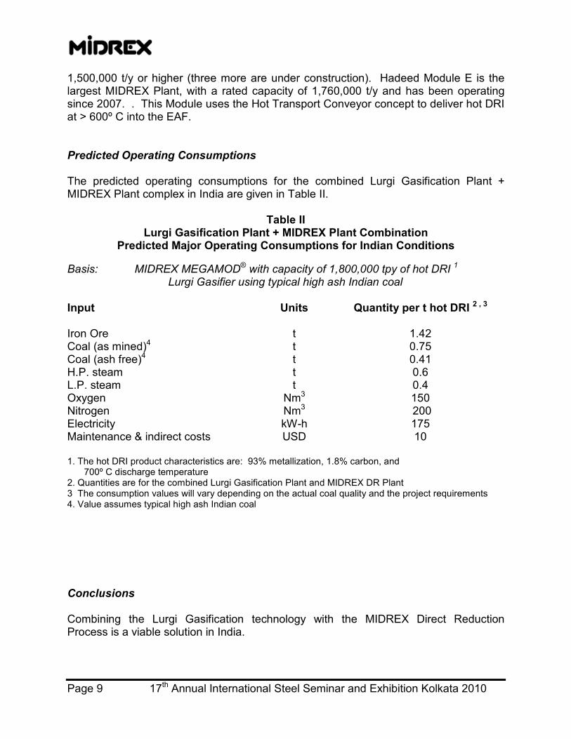
1,500,000 t/y or higher (three more are under construction). Hadeed Module E is the largest MIDREX Plant, with a rated capacity of 1,760,000 t/y and has been operating since 2007. . This Module uses the Hot Transport Conveyor concept to deliver hot DRI at > 600º C into the EAF. Predicted Operating Consumptions The predicted operating consumptions for the combined Lurgi Gasification Plant + MIDREX Plant complex in India are given in Table II.
Table II
Lurgi Gasification Plant + MIDREX Plant Combination Predicted Major Operating Consumptions for Indian Conditions
Basis: MIDREX MEGAMOD® with capacity of 1,800,000 tpy of hot DRI 1 Lurgi Gasifier using typical high ash Indian coal Input Units Quantity per t hot DRI 2 , 3 Iron Ore t 1.42 Coal (as mined)4 t 0.75 Coal (ash free)4 t 0.41 H.P. steam t 0.6 L.P. steam t 0.4 Oxygen Nm3 150 Nitrogen Nm3 200 Electricity kW-h 175 Maintenance & indirect costs USD 10 1. The hot DRI product characteristics are: 93% metallization, 1.8% carbon, and 700º C discharge temperature 2. Quantities are for the combined Lurgi Gasification Plant and MIDREX DR Plant 3 The consumption values will vary depending on the actual coal quality and the project requirements 4. Value assumes typical high ash Indian coal Conclusions Combining the Lurgi Gasification technology with the MIDREX Direct Reduction Process is a viable solution in India.

Page 10 17th Annual International Steel Seminar and Exhibition Kolkata 2010
Advantages of the combined the Lurgi Gasification Plant + MIDREX Plant in India include: • Uses well-proven Lurgi Gasification and Rectisol® technologies. The Lurgi Gasifier
can readily use the low rank, high ash domestic Indian coals as feed material. • Uses well-proven MIDREX Direct Reduction Process. This technology can readily
use domestic Indian iron oxides as feed material. • Produces DRI with quality comparable to natural gas-based MIDREX Plants • The DRI can be hot charged into a nearby electric arc furnace (EAF) to significantly
reduce the EAF electricity requirement and significantly increase the EAF productivity.
• The Lurgi Gasification Plant + MIDREX Plant combination can be paired with an EAF-based mini-mill to produce high quality long or flat steel products
• No coke, coke ovens, or sinter plant required. • Lower specific capital cost than an integrated steel works • Lower air emissions than an integrated steel works • Ability to capture high purity CO2 for sequestering or injecting into oil and gas fields • Much larger capacities than rotary kilns: up to 2.2 Mtpy in a single module • Higher quality DRI product than rotary kilns Contacts For further information on the Lurgi Gasification Plant + MIDREX Plant combination, please contact: Midrex Technologies:
Sales & Marketing Department Phone: +1 704-373-1600 Email: [email protected]
Lurgi:
Product Management Department Phone: +49 69 5808 1780 Email: [email protected]